Embed Size (px)
Citation preview

5G NR and 4G LTECoexistence
White Paper
A Comprehensive Deployment Guide to Dynamic Spectrum Sharing

DSS
2 PDFDSSWP 0320Copyright 2020 © MediaTek, Inc. All rights reserved.
Introduction
DSS Deployment Options and Scenarios MBSFN and non-MBSFN DSS Based Deployment Options
Operators across Europe, Asia and North America have been commercially launching 5G services at an incredible pace never before seen in any previous cellular network generation. From the spectrum perspective, we have seen a nearly simultaneous commercial launches in both FR1 (below 7.125 GHz) and FR2 (millimeter wave). Most FR1 networks have been deployed at mid-bands with a focus on delivering 5G services in 100MHz with higher capacity, for example in n78. While 5G users in such high bandwidth are able to enjoy the benefits of eMBB services, there are obvious and expected challenges that have emerged alongside these deployments. With each new generation of cellular communications the frequencies used get increasingly higher, unlocking more bandwidth, but at the same time shrinking the cell coverage area. In 5G, both coverage and capacity are important aspects, especially in early stage of deployment, with a need for indoor penetration in densely populated urban areas as well as with the coverage of vast rural space outside the cities.
These challenges have been anticipated and there is an obvious solution in sight to provide the coverage layer for 5G in low bands. But obstacles still remain – almost all accessible low bands are occupied by existing technologies, such as LTE. There are still few options on the table, for example 700 MHz across Europe or 600 MHz in the U.S, yet such options are quite limited both in bandwidth and availability. This inevitably raises the question of re-farming the spectrum from LTE to NR. However, despite the tremendously successful uptake of 5G, the industry expects that most of the traffic in the upcoming years will still be carried by LTE networks till 5G device penetration exceeds that of LTE.
Re-farming low band carriers from 4G without a corresponding increase in 5G devices penetration might lead to congestion of the remaining LTE carriers, degrading indoor coverage for LTE users who still represent the majority of the subscriber base. In previous generations it took years to start re-farming; for instance from 2G to 3G and from 2G/3G to 4G. In case of 5G, learning from this experience has led to coverage enhancement solutions that allow a ‘soft’ and flexible re-farming: a “Spectrum Sharing” technique between 4G and 5G, providing a coexistence between 5G and 4G.
Spectrum sharing can be implemented in a static or dynamic manner. The first option means that there will be a dedicated carrier for each technology within the same band. While it has one benefit – it’s transparent to the UE – the spectrum efficiency is insufficient. LTE-only users, currently being a majority, will suffer diminished throughput. Partially or fully overlapped LTE and NR carriers mean the transition is more efficient 5G and 4G coexistence, Dynamic Spectrum Sharing (DSS).
The DSS concept is based on the flexible design of NR physical layer. It uses the idea that NR signals are transmitted over unused LTE resources. With LTE, all the channels are statically assigned in the time-frequency domain, whereas the NR physical layer is extremely flexible for reference signals, data and control channels, thus allowing dynamic configurations that will minimize a chance of collision between the two technologies.
One of the main concepts of DSS is that only 5G users are made aware of it, while the functionalities of the existing LTE devices remain unaffected (i.e. LTE protocols in connected or idle mode). Therefore, fitting the flexible physical layer design of NR around that of LTE is needed in order to deploy DSS on a shared spectrum. This paper discusses the various options of DSS implementation, including deployment challenges, possible impacts to data rates, and areas of possible improvements.
NR offers a scalable and flexible physical layer design depicted by various numerologies. There are different subcarrier spacing (SCS) for data channels and synchronization channels based on the band assigned. This flexibility brings even more complexity because it overlays the NR signals over LTE, which requires very tight coordination between gNB and eNB in order to provide reliable synchronization in radio scheduling.

DSS
2 PDFDSSWP 0320Copyright 2020 © MediaTek, Inc. All rights reserved. 3 PDFDSSWP 0320
Copyright 2020 © MediaTek, Inc. All rights reserved.
DSS
Option-3: Rate-matching-based
RE level rate matching
RB level rate matching
NR overlay
Option-2: Mini-slot-based
LTE CRS
Option-1: MBSFN-based
LTE CRS and PDCCH
Figure 1. DSS Deployment OptionsThe main foundation of DSS is to schedule NR users in the LTE subframes while ensuring no respective impact on LTE users in terms of essential channels, such as reference signals used for synchronization and downlink measurements. LTE Cell Reference Signals (CRS) is typically the main concept where DSS options are designated, as CRS have a fixed time-frequency resource assignment. The CRS resources layout can vary depending on the number of antenna ports. More CRS antenna ports leads to increased usage of Resource Elements (REs). CRS generates from 4.76% (1 antenna port) up to 14.29% (4 antenna ports) overhead in LTE resources. As CRS is the channel used for downlink measurements, avoiding possible collision with CRS is one of the foundations of the DSS options shown in figure 1. The other aspect of DSS design is to fit the 5G NR reference signals within the subframes in a way to avoid affecting NR downlink measurements and synchronization. For that, DSS considers the options shown in figure 1 to ensure NR reference signals such as Synchronization Signal Block (SSB) or Demodulation Reference Signal (DMRS) are placed in time-frequencies away from any collision with LTE signals. MBSFN, option 1 in figure 1, stands for Multi-Broadcast Single-Frequency Network and is used in LTE for point-to-multipoint transmission such as eMBMS (Evolved Multimedia Broadcast Multicast Services). The general idea of MBSFN is that specific subframes within an LTE frame reserve the last 12 OFDM symbols of such subframe to be free from other LTE channel transmission. These symbols were originally intended to be used for broadcast services and are “muted” for data transmission in other LTE UE. Now this idea has been adjusted for use in a DSS concept, so that these reserved symbols are used for NR signals instead of eMBMS. While in general LTE PDCCH can occupy from 1 to 3 symbols (based on cell load), the first two OFDM symbols of such MBSFN subframe are used for LTE PDCCH, and DSS NR UE can use the third symbol. Using MBSFN is completely transparent to legacy LTE-only devices from 3GPP Release 9 onwards, as such LTE UE knows that these subframes are used for other purposes. In this sense this is the simplest way of deploying DSS. This method has disadvantages though. The main one is that if MBSFN subframes are used very frequently and it takes away resources from LTE users, heavily reducing LTE-only user throughput. Note that option 1 shown in figure 1 does not require LTE MBSFN Reference Signals to be used, because the MBSFN subframe is used to mute the subframe for DSS operation only, and LTE CRS shall only be transmitted in the non-MBSFN region (within the first two symbols) of the MBSFN subframe.
The two other options illustrated in figure 1 are dealing with non-MBSFN subframes that contain LTE reference signals. Option 2 is ‘mini-slot’ based; mini-slot scheduling is available in NR for URLLC applications that require extremely low latency. The symbols can be placed anywhere inside the NR slot. In respect to DSS, mini-slot operation just eliminates the usage of the symbols that contain LTE CRS and schedule only free ones for NR transmission. The basic limitation of this method comes from the concept itself. It is not very suitable for eMBB applications as too many resources are outside of NR scheduling. However it still can be utilized in some special cases like 30 kHz SSB insertion which will be described later in this paper.
Option 3 is based on CRS rate matching in non-MBSFN subframes, and it is expected to be the one most commonly used for NR data channels. In this option, the UE performs puncturing of REs used by LTE CRS so that the NR scheduler knows which REs are not available for NR data scheduling on PDSCH (Physical Downlink Shared Channel). The implementation of this option can be either Resource Block (RB)-level when the whole RB containing LTE CRS is taken out of NR scheduling, or RE-level where NR PDSCH scheduling avoids particular REs only. The end result of this method is that the scheduler will reduce the NR PDSCH transport block size as the number of REs available for scheduling become less in a slot.
For better spectral efficiency, CRS RE-level rate-matching is preferred when compared to RB-level rate matching in NR PDCCH/PDSCH 15 kHz SCS. However for NR PDCCH/PDSCH at 30 kHz SCS, only RB-level rate matching is suitable because of the difference in numerologies with LTE. Another application for RB-level rate matching is to avoid collisions with the other LTE synchronization channels (PSS/SSS/PBCH). Table 1 compares the available REs per RB

DSS
4 PDFDSSWP 0320Copyright 2020 © MediaTek, Inc. All rights reserved.
in a slot, depending on the underlying LTE CRS configuration. As shown in table 1, LTE CRS within an RB occupies four symbols (#0, 4, 7, 11) for one or two antenna ports and two additional symbols (#1, #8) for four CRS antenna ports. Each CRS symbol consists of two subcarriers for each antenna port. However, since the first two symbols are occupied by LTE PDCCH, they are not considered for rate matching overhead of the NR PDSCH. Then, the overall overhead from CRS to available NR PDSCH symbols becomes 3 CRS symbols * 2 subcarriers = 6 RE for one antenna port, 3 CRS sym-bols * 4 subcarriers = 12 RE for two antenna ports, and 4 CRS symbols * 4 subcarriers = 16 RE for four antenna ports. As NR PDSCH scheduling can only occur after the second symbol in the slot where the third symbols is occupied for NR PDCCH (first two symbols are for LTE PDCCH), as a result, NR PDCSCH is scheduled with 11 symbols out of the total 14 symbols available in a slot. Then, 12 RE * 11 Symbols results in 132 RE available in a slot for NR PDSCH. In the case of one LTE CRS antenna port, the total available NR PDSCH REs available in a slot per one RB is 132-6 = 126 REs, 132-12 = 120 REs with two CRS antenna ports, and 132-16 = 116 REs with four CRS antenna ports. On the other hand, if the entire RB in a slot is being muted, 3 (one and two CRS ports) and 4 (otherwise) symbols will be rate matched, resulting in 12 RE per RB *(11 symbols available for PDSCH – 3 CRS symbols muted within NR slot) = 96 REs available for NR PDSCH with one or two CRS antenna ports, and 12 RE per RB *(11 symbols available for PDSCH – 4 CRS symbols muted within NR slot) = 84 REs available for NR PDSCH with four CRS antenna ports. This means that the transport block size for NR PDSCH will be higher in RE rate matching and hence better spectral efficiency.
Using one of the DSS options does not eliminate others. Despite each one has its own advantages and disadvantages, they all can find their proper application depending on particular configuration and in some cases they can be mixed to enable an optimal DSS solution.
This section shows examples of NR SSB transmissions to demonstrate the importance of combining different DSS deployment options. SSB consists of synchronization signals (PSS and SSS) and a Physical Broadcast Channel (PBCH). For a half frame (5 msec) SSB transmission, the SSB contains 4 OFDM symbols in the time domain and 240 contiguous subcarriers (20 RBs) in the frequency domain.
The subcarrier spacing (SCS) used for SSB is dependent on the frequency band. In case of FR1, it can be either 15 kHz or 30 kHz. In time domain, there is a number of options of SSB location depending on the band used and SCS. 3GPP TS 38.101-1 contains pre-defined tables of starting symbol indices per band, marked as Case A, B or C in FR1. Table 2 illustrates SSB allocation in time domain for FR1 cases in a frequency range ≤ 3 GHz only, where DSS can be applied at the moment. In the frequency domain, up to four SSB beams (SSBs index #0, 1, 2 and 3 with Lmax=4, configured to UE by higher layer parameter ssb-PositionsInBurst as a bitmap) can be transmitted in the FR1 range ≤ 3 GHz.
LTE CRS Configuration RE rate-matching RB rate- matching
LTE 1 CRS port: 6 RE overhead in NR PDSCH region, or 3 symbols with RB
Rate Matching
126 RE 96 RE
LTE 2 CRS port: 12 RE overhead in NR PDSCH region, or 3 symbols with RB
Rate Matching
120 RE 96 RE
LTE 4 CRS port: 16 RE overhead in NR PDSCH region, or 4 symbols with RB
Rate Matching
116 RE 84 RE
SSB Subcarrier Spacing f ≤ 3 GHz Band Example (f ≤ 3 GHz) based on TS 38.101-1
Case A :15 kHz
NR SSB Symbols within one LTE subframe =(2,3,4,5),(8,9,10,11)
FDD band n3, n5, or TDD band n41
Case B :30 kHz
NR SSB Symbols within one LTE sub-frame = (4,5,6,7),(8,9,10,11),(16,17,18,19),(2
0,21,22,23)
FDD band n5
Case C :30 kHz
NR SSB Symbols within one LTE sub-frame = (2,3,4,5),(8,9,10,11),(16,17,18,19),(2
2,23,24,25)
TDD band n41
Table 1. RE-level vs. RB-level CRS Rate Matching
Table 2. SSB Starting Symbol Indices for FR1
Combining DSS Deployment Options: SSB Example

DSS
4 PDFDSSWP 0320Copyright 2020 © MediaTek, Inc. All rights reserved. 5 PDFDSSWP 0320
Copyright 2020 © MediaTek, Inc. All rights reserved.
DSS
As discussed in previous section, DSS can be implemented in MBSFN or non-MBSFN subframes. For NR PDSCHchannel used for data transmission, rate matching can be used to avoid the REs occupied by LTE CRS. However,for NR SSB, puncturing the channel becomes impossible as it may affect the downlink measurements andsynchronization. Therefore, SSB in a DSS cell must be transmitted in a way to totally avoids all symbols and subcarriers occupied by LTE CRS. To better understand whether we shall opt for MBSFN or non-MBFSN frame to transmit SSB, we need to take a look at what can be the impact in each case.
Starting with non-MBSFN subframe which is shown on figure 2. The upper part of the figure depicts NR resource grid, while the lower part is the corresponding LTE non-MBSFN subframe. In this paper, it is always assumed that NR PDCCH/PDSCH SCS is 15 kHz to match the LTE subframe, which is expected to be the case used for the initial DSS implementation. With NR PDCCH/PDSCH SCS of 15 kHz, there is one NR slot per NR subframe and 10 NR slots per NR frame. Therefore, in this paper, the terms “slot” and “subframe” are used interchangeably. The paper assumes the channel configurations of 20 MHz bandwidth for DSS, unless mentioned otherwise.
Starting with SSB 15 kHz Case A on the leftmost grid of figure 2 shows both SSB beams that can be transmitted in one NR slot (i.e. one LTE subframe) colliding with LTE CRS. This makes such configuration totally not suitable for DSS, because once any SSB symbol collides with CRS it eliminates transmission of the whole SSB beam. The central grid in figure 2 shows SSB 30 kHz Case B where all four beams can be transmitted in one slot because of wider SCS than the NR PDCCH/PDSCH 15 kHz SCS. One out of four SSB beams can be transmitted from gNB avoiding collision for SSB#0, yet other 3 bursts remain unavailable at least in LTE four antenna ports scenario. In this case NR mobility can be affected as we are left with one beam only. SSB 30 kHz Case C represented in the right side of figure 2. Just like Case A, it has collisions with LTE CRS in all four SSB beams making its use impossible in LTE four CRS port scenario and limited to only one SSB beam in case LTE one or two CRS ports.
Different results can be achieved using an MBSFN subframe for SSB transmission and figure 3 clearly shows why. Here, the same SSB cases as in figure 2 are demonstrated, but the frame consists of MBSFN subframe instead. Since MBSFN mutes the entire 12 symbols of the subframe, then SSBs do not have LTE CRS collision, and the impact on all SSB cases is minimal.
0 1 2 3 4 5 6 7 8 9 10 11 12 13 0 1 2 3 4 5 6 7 8 9 10 11 12 13 0 1 2 3 4 5 6 7 8 9 10 11 12 13
0 1 2 3 4 5 6 7 8 9 10 11 12 13
SSB
#0
SSB
#2
SSB
#1
SSB
#3
0 1 2 3 4 5 6 7 8 9 10 11 12 13
SSB
#0
SSB
#2
SSB
#1
SSB
#3
SSB #2 & #3 occupy the next slotFreq (PRB)
0 1 2 3 4 5 6 7 8 9 10 11 12 13
SSB
#0
SSB
#1
PRB#19 of SSB
PRB#10 of SSB
PRB#0 of SSB
NR SSB Symbol Index (PDSCH with 15kHz, SSB with 15kHz case A)
LTE Symbol Index (Non-MBSFN, with PDCCH and CRS)
NR SSB Symbol Index (PDSCH with 15kHz, SSB with 30kHz case B)
LTE Symbol Index (Non-MBSFN, with PDCCH and CRS)
NR SSB Symbol Index (PDSCH with 15kHz, SSB with 30kHz case C)
LTE Symbol Index (Non-MBSFN, with PDCCH and CRS)
NR SSB (Possible to transmit)NR SSB (NOT Possible to transmit)NR PDSCH (NOT Rate Matched)NR PDSCH (Rate Matched RE or RB may occur)NR DMRS (POS1, Single Symbol, CDM Group#3)
LTE CRS REs for 1,2 portsLTE CRS REs for 4 portsLTE PDCCH
Figure 2. Impact of Spectrum Sharing on NR SSB Channel: Non-MBSFN
Time
Time
Time
Time
Time
Time

DSS
6 PDFDSSWP 0320Copyright 2020 © MediaTek, Inc. All rights reserved.
NR SSB (Possible to transmit)
NR SSB (NOT Possible to transmit)
NR PDSCH (NOT Rate Matched)
NR DMRS (POS1, Single Symbol, CDM Group#3)
LTE CRS REs for 1,2 ports
LTE CRS REs for 4 ports
LTE PDCCH
LTE cell-specific reference signals and PDCCH shall only be transmitted in the non-MBSFN region of the MBSFN subframe
Figure 3. Impact of Spectrum Sharing on NR SSB Channel: MBSFN
The only limitation for SSB Case C comes from LTE PDCCH and CRS transmitted in the first two symbols of the subframe which cause collision with SSB#0 making three SSBs available out of four. However, for MBSFN case, subframe alignment with NR SSB slots is essential. Not all subframes can be allocated as MBSFN (e.g. for LTE-FDD, subframes #0 and #5 are not used for MBSFN as discussed in later sections). Therefore, not all SSB beams can be valid for MBSFN subframes. For SSB Case A, SSB #0 and #1 cannot be transmitted within MBSFN pattern if the corresponding slot is aligned to MBSFN subframe #0. To solve this, the cell can allocate SSB beam #2 and/or #3 that are transmitted in the second slot, which fall within a valid MBSFN subframe #1. For SSB Case B and C with 30 kHz SCS, all four SSBs would fall into LTE subframe #0 if fully aligned with LTE subframes. In this case, LTE and NR frame alignment is needed in a way SSB slot overlaps exactly within possible MBSFN subframes other than #0 or #5 (e.g. SSB can start at NR slot aligned with one of valid LTE MBSFN sync subframes).
This SSB mapping perfectly demonstrates the importance of combining different DSS options. MBSFN-based DSS is not usually optimal for data, to avoid backward impact to LTE throughput. However, using MBSFN subframe is important in providing SSB transmission based on the SSB SCS, thus a preferred DSS solution would be to mix of both methods. This is especially important for the majority of ≤ 3 GHz bands that are the ones most anticipated for DSS usage since they are restricted to SSB case A or B (except for n41 that can support SSB cases C with 30 kHz SCS). In general for ≤ 3 GHz bands, 3GPP in TS 38.213 states that if a 30 kHz SS/PBCH block SCS is indicated by subcarrierSpacing, Case B applies for frequency bands with only 15 kHz SSB SCS defined in TS 38.101-1.
The design concepts of DSS on the network side discussed in the previous section require features to be supported by a DSS capable UE. The most important features are summarized in table 3 and those essential for the initial deployment will be described in more details in this section. The table comes with a reference to 3GPP TS 38.822 containing Layer 1 Feature List Index and TS 38.331 RRC Field Names, if applicable. Not every DSS deployment option requires all of those features so suitability indication is also included.
DSS Related Features in 3GPP
0 1 2 3 4 5 6 7 8 9 10 11 12 13
0 1 2 3 4 5 6 7 8 9 10 11 12 13 0 1 2 3 4 5 6 7 8 9 10 11 12 13
SSB
#0
SSB
#2
SSB
#1
SSB
#3
NR SSB Symbol Index (PDSCH with 15kHz, SSB with 30kHz case C)
LTE Symbol Index (MBSFN, with PDCCH and CRS)
Aligned with valid MBSFN Subframe (e.g. not#0)
Time
0 1 2 3 4 5 6 7 8 9 10 11 12 13
0 1 2 3 4 5 6 7 8 9 10 11 12 13 0 1 2 3 4 5 6 7 8 9 10 11 12 13
SSB
#0
SSB
#2
SSB
#1
SSB
#3
NR SSB Symbol Index (PDSCH with 15kHz, SSB with 30kHz case B)
LTE Symbol Index (MBSFN, with PDCCH and CRS)
Aligned with valid MBSFN Subframe (e.g. i not#0)
Time
0 1 2 3 4 5 6 7 8 9 10 11 12 13
Freq (PRB)
0 1 2 3 4 5 6 7 8 9 10 11 12 13
SSB
#2
SSB
#3
PRB#19 of SSB
PRB#10 of SSB
PRB#0 of SSB
NR SSB Symbol Index (PDSCH with 15kHz, SSB with 15kHz case A)
LTE Symbol Index (MBSFN, with PDCCH and CRS)
E.g Subframe #1
Time
DSS
6 PDFDSSWP 0320Copyright 2020 © MediaTek, Inc. All rights reserved. 7 PDFDSSWP 0320
Copyright 2020 © MediaTek, Inc. All rights reserved.
DSS
LTE MBSFN Support
LTE CRS Rate Matching
Feature Layer-1 Feature List Index
(TS 38.822)
Short Explanation Example of Field Name in RRC
(TS 38.331)
DSS Option
1 2 3
LTE MBSFN subframe LTE feature Shared with LTE MBSFN subframes
mbsfn-SubframeConfigList
O
NR SSB with 30 kHz SCS Based on band For the applicable bands in FR1
subcarrierSpacing O O
LTE CRS rate matching 5-28 RE-level rate matching. Allows transmission of
NR PDSCH in non-MBSFN subframes
rateMatchingLTE-CRS O
General rate matching pattern
5-26 RB-level rate matching. Al-lows PDSCH rate matching
around LTE PSS/SSS and PBCH
rateMatchingResrcSetSemi-Static
O
NR PDCCH in symbol 2 3-1 Search Space Mapping for CORESET
monitoringSymbo WithinSlot
O O O
PDCCH monitoring on any up to 3 consecutive
symbols
3-2 NR UE capability to miti-gate DSS impact on PDCCH
capacity
pdcchMonitoringSingleOccasion
O O
PDSCH Mapping Type A (< 7 OFDM symbols)
5-6 Data channel mapping pdsch-MappingTypeA O O O
PDSCH Mapping Type B 5-6a pdsch-MappingTypeB OAlternative additional NR
DMRS location2-6b For co-existence with LTE
CRSadditionalMRS-DL-Alt O
NR TRS in symbol 6 and 10
Mandatory for NR Used to avoid collision with LTE CRS
Refer to table 11 in this paper
O O O
Flexible NR CSI-RS Mandatory for NR O O O7.5 kHz UL shift Mandatory for some
NR bandsEnable the NR UL trans-
mission with a 7.5 kHz shift to the LTE raster
frequencyShift7p5khz O O O
Table 3. DSS Related UE Features Summary
LTE MBSFN support is an essential feature for Option 1 discussed in previous section. NR UE gets informed about MBSFN subframe presence by higher layer (RRC) in the cell from lte-CRS-ToMatchAround that sets up RateMatchPatternLTE-CRS used to configure a pattern to rate match around LTE CRS, and may also configure mbsfn-SubframeConfigList representing LTE MBSFN subframe configuration. There are two ways in higher layer to inform the NR UE of when to apply LTE MBSFN subframes: 1) in case of NR standalone deployment, mbsfn-SubframeConfigList is part of ServingCellConfigCommon which a NR UE would typically acquire from System Information (e.g. SIB1) when accessing the cell from idle mode; 2) in case of NR standalone or non-standalone deployment, the same is configured to UE in connected mode by rrcConnectionReconfiguration (with sync) message for the serving cell, which can be common (cell specific) or dedicated (UE specific, configured by ServingCellConfig for SpCell or an SCell of an MCG or SCG).
MBSFN pattern in FDD cell can configure at most subframes #1, #2, #3, #6, #7, #8 with the sequence of one or four radio frames, which accounts for a maximum of 60% of radio resources. In 3GPP Release 14, this possibility was extended for FDD MBSFN subframes #4 and #9. This configuration should be carefully planned because when more MBSFN subframes are configured for DSS usage, the impact on LTE-only user throughput increases due to more normal LTE subframes being unavailable for scheduling. Note that LTE eNB should configure MBSFN subframe patterns similar to the ones configured to the UE in NR serving cell with proper frame alignment. In LTE, the MBSFN pattern can be configured to LTE UEs in LTE SIB2 in idle mode or dedicated RRC messages in connected mode.
LTE CRS rate matching (feature 5-28) is mandatory for Option 3 discussed in previous section. The support is indicated in UE capability with rateMatchingLTE-CRS information element per band. In the same way explained above,

DSS
8 PDFDSSWP 0320Copyright 2020 © MediaTek, Inc. All rights reserved.
the network indicates to the UE RateMatchingPatternLTE-CRS in a NR cell and includes parameters to derive RE positions of LTE CRS. The rate matching configuration contains nrofCRS-Ports consisting of LTE-CRS antenna ports 1, 2 or 4 ports, among other parameters shown in later sections. 3GPP Release 15 allows lte-CRS-ToMatchAround to configure common RS, in 15 kHz subcarrier spacing applicable only to 15 kHz subcarrier spacing PDSCH, of one LTE carrier in a NR serving cell configuration. This means that if LTE carrier aggregation is used, CRS rate matching will be applied for CC#1 only while other carriers will stay out of spectrum sharing. This issue is addressed in 3GPP Release 16. Additionally, when NR transmission is activated on the LTE band, the LTE CRS is still transmitted in the same time. As a result, during initial access in NR standalone, it is possible that NR PDSCH carrying SIB1 to be configured in symbols colliding with LTE CRS, but the NR UE is not aware of that until it receives the RRC information shown above. This point is discussed in later section of the paper.
General RB Rate Matching Pattern (Feature 5-26) is used for RB-level rate matching mainly for the case of a collision with LTE PSS/SSS and PBCH, as these channels occupy resources at RB level. UE support is reported by rateMatchingResrcSetSemi-Static to indicate whether device supports receiving PDSCH with resource mapping that excludes the REs corresponding to resource sets configured with RB-symbol level granularity following the semi-static configuration. The UE may be configured with any of the following higher layer parameters indicating REs declared as not available for PDSCH:
• rateMatchPatternToAddModList given by PDSCH-Config, by ServingCellConfig.
• ServingCellConfigCommon and configuring up to 4 RateMatchPattern(s) per bandwidth part (BWP) and up to 4 RateMatchPattern(s) per serving-cell.
This feature (feature 2-6b) is designed to avoid collision of additional Demodulation Reference Symbol (DMRS) in case PDSCH mapping Type A when single-symbol DMRS is used. DMRS additional symbol located at index #11 will collide with LTE CRS as shown in figure 4, causing higher PDSCH BLER especially in poor radio conditions. For this reason, the support of this feature is expected from all DSS enabled devices.
General RB Rate Matching Pattern
Alternative DMRS Location
11
10
9
8
7
6
5
4
3
2
1
0
0 1 2 3 4 5 6 7 8 9 10 11 12 13
0 1 2 3 4 5 6 7 8 9 10 11 12 13
NR PDSCH SLIV = 40( 13 symbols)Freq
NR PDSCH DM-RS (Possible to transmit)
NR PDSCH DM-RS ( NOT Possible to Transmit)
NR PDSCH DM-RS ( Delayed by one symbol)
NR PDSCH (Not Rate Matched)
NR PDSCH ( Rate Matched RE or RB may occur)
LTE CRS REs for 1 or 2 ports
NR Symbol Index (PDSCH with 15KHz)
LTE Symbol Index
Figure 4. Alternative DMRS Location
Time
Time

DSS
8 PDFDSSWP 0320Copyright 2020 © MediaTek, Inc. All rights reserved. 9 PDFDSSWP 0320
Copyright 2020 © MediaTek, Inc. All rights reserved.
DSS
Examples of NR Channel Mapping and Related 3GPP Features
NR PDSCH Mapping Types
Example 1: NR PDCCH/PDSCH SCS=15 kHz, Without SSB
When this feature is enabled, DMRS is delayed to symbol index #12 instead of #11. All following conditions must be met:
• The higher-layer parameter lte-CRS-ToMatchAround is configured; • The higher-layer parameters dmrs-AdditionalPosition is equal to ‘pos1’ and starting position for DRMS in parame-
ter dmrs-TypeA-Position = 3; • The UE has indicated it is capable of additionalDMRS-DL-Alt.
The other features shown in table 3 will be discussed in next sections in the paper as applicable to the examples shown.
To understand possible network configurations and their influence on UE, we will first take a look at how the resources are allocated in the time domain. NR supports two types of PDSCH allocation. One of those is Type A and is a slot-based mapping. PDSCH time allocation can start from symbols (S) 0,1,2,3 and has a length (L) of 3 to 14 symbols. This mapping is commonly used for eMBB services. Another one is Type B or mini-slot based. PDSCH time allocation can start from any symbol in the slot but has length options limited to 2, 4 or 7 symbols in case of normal Cyclic Prefix. This one is a preferred type for URLLC services as it provides better latencies where data transmissions not restricted to slot boundaries. The UE receives PDSCH mapping type and start position/length from PDCCH and RRC related configurations, with SLIV parameters. SLIV table is defined in 3GPP TS 38.214 and they both are shown in figure 5.
The current 5G deployment is typically using PDSCH mapping Type A. However for DSS deployment, PDSCH mapping Type B can be the only available option for some situations.
Let’s take a look at how DSS will change the time-frequency resources layout in case of NR PDCCH/PDSCH transmission with 15 kHz SCS (slot does not carry any other reference signal than DMRS) and what additional features in the UE side will be required. In figure 6 shows this NR slot without and with DSS operation. The example shown does not contain SSB transmission.
Figure 5. NR PDSCH Mapping Types in Time Domain
PDSCHDCI
slot
4 OF DM symbols
Index Slot offset
Start symbol
Length PDSCHmapping
type
0 0 2 12 A
1 0 2 10 A
2 1 3 4 B
... ... ... ... ...
Jointly encoded
(S+L+1) (≤ 13) if (L-1) ≤ 7=> SLIV+SLIV%14 = 28-(S+L) (> 13) else 0 < l ≤ (14-s) => s < ( l + S ) ≤ 14
- PDSH mapping type A - Start symbol (S): 0, 1, 2, 3 in a slot - Length (L): 3 - 14 symbols (slot-based)
- PDSCH mapping type B - Start symbol (S): any - Lenght (L):2, 4, 7, symbols (mini-slot)
RRC configured

DSS
10 PDFDSSWP 0320Copyright 2020 © MediaTek, Inc. All rights reserved.
NR DMRS for PDSCH (POS1, Single Symol, CDM Group #3, Starting at 4th
NR PDSCH Region (Not Rate Matched)
NR PDCCH Region ( Control)
NR PDSCH Symbols where REs/RB can be rate matche with LTE CRS
LTE PDCCH
LTE CRS Port 1
LTE CRS Port 0
LTE CRS Port 3
LTE CRS Port 2
11
10
9
8
7
6
5
4
3
2
1
0
0 1 2 3 4 5 6 7 8 9 10 11 12 13
11
10
9
8
7
6
5
4
3
2
1
0
0 1 2 3 4 5 6 7 8 9 10 11 12 13
NR Cell without spectrum sharing LTE/NR Cells with spectrum sharing
Symbol Index (one slot) Symbol Index (one slot)
Figure 6. NR PDCCH/PDSCH SCS=15 kHz (without SSB)
In the left side of this figure an example of dedicated NR carrier transmission is shown with 11 PDSCH symbols. The first 3 symbols are originally occupied with PDCCH, symbols 3 and 11 contain DMRS with a configuration that fully occupies all REs, and the rest 9 symbols are utilized by PDSCH. The right side of the figure has the same NR slot with spectrum sharing enabled in a cell. LTE in the given example is using four antenna port configuration. The first 2 symbols will be occupied by LTE PDCCH and there will be LTE CRS in the assigned positions as shown. This will take symbols #0 and #1 from NR use completely and will require special handling for slots #4, #7, #8 and #11. The following features will be used for this configuration to show DSS mapping will be different:• Feature 3-1 allowing NR PDCCH to occupy symbol #2 based on NR PDCCH higher layer parameters monitor-
ingSymbolsWithinSlot (bitmap example shown later in table 11). • Symbol #11 which was originally occupied by NR DMRS in case of DSS collides with LTE CRS. This is the main use
case for Alternative DMRS Location feature (2-6b). In case it is supported by the UE, NR DMRS will be moved to symbol #12.
• NR PDSCH mapping Type A used, starting from symbol #3 with 11 symbols length (mapping come from SLIV=66).• Either feature 5-28 or 5-26 for RE or RB-level CRS rate matching respectively to avoid collision with LTE CRS for
NR PDSCH. Available REs for NR PDSCH will be further reduced by the 16 LTE CRS REs within this region in a slot, in case of RE-level CRS rate matching is used.
In case NR SSB is added to the slot based on the SSB periodicity (typically set as 20 msec in a cell), the slot mapping will be different. Figure 7 shows the cases with and without DSS. The figure uses the scenario when there are 2 SSB beams with 15 kHz SCS in the dedicated NR deployment without DSS, and one SSB beam with 30 kHz SCS in the DSS scenario.
Example 2: NR PDCCH/PDSCH SCS=15 kHz, With SSB
Freq Freq
Time Time

DSS
10 PDFDSSWP 0320Copyright 2020 © MediaTek, Inc. All rights reserved. 11 PDFDSSWP 0320
Copyright 2020 © MediaTek, Inc. All rights reserved.
DSS
Figure 7. NR PDCCH/PDSCH SCS=15 kHz (with SSB)
NR PDSCH DMRS (POS1, Single symbol, CDM Group#3)
NR PDSCH Region ( Not Rate Matched )
NR PDCCH Region ( Control)
NR PDSC Symbols where REs/RB can be rate matched with LTE CR
SSB#0 with 30kHz SCS ( DSS), or SSB#0 and #1 with 15kHz ( without DSS)
No NR PDSCH scheduling
LTE PDCCH
LTE CRS Port 1
LTE CRS Port 0
LTE CRS Port 3
LTE CRS Port 2
11
10
9
8
7
6
5
4
3
2
1
0
0 1 2 3 4 5 6 7 8 9 10 11 12 13 0 1 2 3 4 5 6 7 8 9 10 11 12 13
Freq
Time
LTE/NR Cells with spectrum sharing
NR SSB Symbol Index (SSB with 30kHz Case B)
Symbol Index ( Non-MBSFN,15 KHz with NR PDSC/PDCCH & LTE PDCCH/CRS
0 1 2 3 4 5 6 7 8 9 10 11 12 13
11
..
1
0
11
10
9
8
7
6
5
4
3
2
1
0
0 1 2 3 4 5 6 7 8 9 10 11 12 13
Freq
Time
NR Cell without spectrum sharing
NR Symbol INdex ( PDSCH/PDCCH/SSB with 15kHz)
Nex
t RB
Last
SSB
RB
The left side again shows this scenario with dedicated NR carrier – two SSB beams with 8 symbols are occupied by SSB while others are free to use for other purposes. But when DSS is enabled a number of limitations may occur in the slot mapping:• It is mandatory to change SSB numerology to 30 kHz as it was discussed in previous section (if allowed by • frequency band).• It becomes impossible to use the second SSB for non-MBSFN frame because we are unable to avoid collision with
LTE CRS.
DSS
12 PDFDSSWP 0320Copyright 2020 © MediaTek, Inc. All rights reserved.
• Since symbols #0 and #1 are utilized by LTE PDCCH and symbol #2 and #3 are now occupied by SSB there is no room for NR PDCCH in its regular location anymore. NR PDCCH cannot be pushed to symbol #4 as well because it carries LTE CRS. In this case we completely run out of symbols that are allowed to start NR PDSCH mapping Type A as NR PDCCH is now naturally pushed to symbol #5 and NR PDSCH is even beyond this at symbol #6. It leaves no other option than to switch to mapping Type B (feature 5-6b required). The problem with Type B though is that its maximum length is limited to 7 symbols which means that starting with #6 we can last only up to #12 leaving #13 effectively empty.
• Support of feature 3-2 PDCCH monitoring on any up to 3 consecutive symbols is additionally required for this deployment to provide monitoring of PDCCH by the UE since it is now moved from the first symbol of the slot.
These limitations and complexity once again prove that it’s more effective to use MBSFN in case SSB is present in a slot. Next sections will show clearly how all these cases are dealt with in more details.
Due to LTE CRS being present in the first 1-2 symbols of every subframe (for 2 or 4 ports, respectively) both in MBSFN and Non-MBSFN subframes, the NR PDCCH can start the earliest in the third symbol. In early DSS deployment, NR PDCCH will be transmitted in symbol 2 with a duration of a single symbol. In LTE PDCCH frequency domain mapping, each Control Channel Element (CCE) consists of 36 REs (9 Resource Element Group, REG*4 REs) while in NR each CCE consists of 72 REs (6 REG*12 REs). This makes the available CCE in 20 MHz with 15 kHz PDCCH SCS as shown in the table 4.
Based on the CCE availability, we can estimate the capacity of PDCCH in terms of number of users scheduled in a cell as shown in figure 8. The following inputs apply:• VoIP (either VoLTE or VoNR) users are scheduled every 20 msec (voice packet) and 160 msec (SID packets), • assuming 50% voice activity factor. Data users are scheduled every subframe.• Mean CCE is assumed using aggregation levels (AL) 1,2,4,8 for fair comparison between LTE and NR (NR can use AL
16 as well, which will reduce the CCE availability even further if scheduled by network, based on DCI sizes and RF conditions).
• The estimation does not consider any CCE overhead from other CORESET (Control Resource Set) such as Type0/0A/2 CORESET (used for System Information, RACH, paging, etc...).
Impact of Spectrum Sharing on NR PDCCH Channel Capacity
Table 4. Available CCE for PDCCH in LTE and NR (Note not all REG can be usable and limited by # of RBs in the cell)
Number of CCE available LTE in 20MHz (NG=1) with 2x2 MIMO NR in 20MHz 15kHz SCS1 Symbol PDCCH 17.444 17.667
2 Symbols PDCCH 50.778 35.333
3 Symbols PDCCH 84.111 53.000
PDCCH Case
Mean Symbols
Mean CCE Max CCE
More 1-Symbol
PDCCH Utilization
1.00 4.47 NR=17.70LTE=17.40
More 2-Symbol
PDCCH Utilization
1.92 4.21 NR=33.84LTE=47.95
More 3-Symbol
PDCCH Utilization
2.83 3.62 NR=49.97LTE=78.39

DSS
12 PDFDSSWP 0320Copyright 2020 © MediaTek, Inc. All rights reserved. 13 PDFDSSWP 0320
Copyright 2020 © MediaTek, Inc. All rights reserved.
DSS
140.00
120.00
100.00
80.00
60.00
40.00
20.00
0.00
More 1-Symbol PDCCH Utilization More 2-Symbol PDCCH Utilization More 3-Symbol PDCCH Utilization
65.09 65.82
99.10
127.61
69.93
81.34
3.91 5.95 7.663.95 4.20 4.88
1-Sym=99.83%, 2-Sym=0.14%, 3-Sym=0% 1-Sym=18.83%, 2-Sym=70.82%, 3-Sym=10.35% 1-Sym=0.07%, 2-Sym=17.02%, 3-Sym=82.92%
NVoIP LTE Ndata LTE NVoIP NR Ndata NR
Figure 8. Average Number of Scheduled Users/Cell in b3/n3 with 20 MHz, SCS=15 kHz and 2x2 MIMO
The network scheduler generally uses more PDCCH symbols when the load increases, and tends to use more CCEs for users in bad radio conditions, and the table in figure 8 shows the trend from live network statics used to dimension the users/cell in the figure, assuming that mean PDCCH CCE and symbols apply the same way to LTE and NR for the sake of comparison. Based on the discussion around table 4, the UEs in the cell will have less number of CCEs for NR PDDCH, therefore, less number of scheduled users in 15 kHz SCS compared to LTE since in DSS, LTE can use two PDCCH symbols and NR will be limited to one, affecting VoIP users dimensioning the most (if DSS is deployed with VoNR in standalone). There are several options to improve NR PDCCH capacity in DSS including: • More than one CORESET configurations per BWP in addition to CORESET0, which allows flexible PDCCH region
size and enhanced multiplexing (feature 3-3)• May require dynamic rate-matching of NR PDSCH around NR PDCCH (feature 5-27a) to improve the wasted • resources of using multiple CORESET around symbols in which not all CCE are utilized.• Feature 3-5b with multiple NR PDCCH monitoring occasions where one occasion of NR PDCCH can start from
symbol #2 and another towards the end of a slot (where LTE PDCCH or CRS do not exist). This option involves a complicated scheduler behavior as it enables a mixture of same-slot and cross-slot scheduling and a packet segmentation.
• PDSCH mapping type-B (feature 5-6a) with Support for type B length 9/10 in Rel-16. This allows more symbols to be allocated for NR PDCCH increasing the capacity, while also adding more OFDM symbols for data channel.
In NR non-standalone (NSA) deployment, the UE does not necessary need to receive NR system information blocks (such as SIB1) or any NR paging messages because all the information can be sent to the UE through LTE control plane signaling in connected mode when the 5G Secondary Cell Group cell (SCG) is added. However, in NR standalone (SA) deployment as shown in figure 9, the UE is required to read the Master Information Block (MIB), Remaining Minimum System Information (RMSI such as SIB1), and all Other System Information (OSI such as SIB2, SIB3, etc..) during cell search or for other idle mode operations. In Idle mode, prior to receiving SIB1, the DSS UE in SA is unaware of the LTE reference signals. 3GPP specifications do not allow the activation of rate matching around CRS in idle mode and
Impact of Spectrum Sharing on NR System Information and Paging Transmission in Standalone

DSS
14 PDFDSSWP 0320Copyright 2020 © MediaTek, Inc. All rights reserved.
SIM1 Config
connected mode until a certain point in the call setup when the signaling messages are sent to the UE indicating DSS operation. Therefore, decoding PDSCH and DMRS required for initial cell access in SA idle mode becomes challenging.
Non-StandaloneMode
Standalone Mode
PBCH PBCH
MIB
MIB
LTE Dedicated Signaling (RRC
Reconfig Message)PDCCH & PDSCH
RMSI/OSI Parameters for
SCG cell
RMSI
OSI
5G system information
structure
Other System Information (OSI)
Periodic Broad-casting (on
PDSCH)
On demand (based on SIB 1 and RRC state)
Upon detection of SSB, the UEdetermines that a control resourceset for Type0-PDCCH commonsearch space, is present if kssb ≤ 23for FR1 or if kssb ≤1 for FR2
Figure 9. System Information in 5G NSA vs. SA Deployment
According to TS 38.214 clause 5.1.6.2, when receiving PDSCH scheduled by DCI format 1_0 (Downlink Control Informa-tion 1_0 carried on NR PDCCH is used for System Information, paging messages and RACH) or receiving PDSCH before dedicated higher layer configuration of DMRS for PDSCH, the UE shall assume that for FR1, PDSCH mapping type A is used with DMRS of up to two additional symbols (dmrs-AdditionalPosition=’pos2’) in a slot, with positions according to the PDSCH duration. At this point, the DSS UE is not aware of the presence of LTE CRS in idle mode, and as a result there must be some considerations taken by the gNB scheduler, as follows: • In FR1, TS 38.214 specifies tables for default NR PDSCH mapping in time domain. As SIB1 is broadcasted with a
minimum information by MIB (it just tells UE how to decode NR PDCCH), then UE can use default PDSCH time do-main resource allocation A in tables 5.1.2.1.1-1 and 5.1.2.1.1-2 in TS 38.214. For other SIBs (OSI), the PDSCH mapping can be sent to the UE in SIB1 itself, but most likely will need to follow same considerations discussed below due to additional DMRS locations.
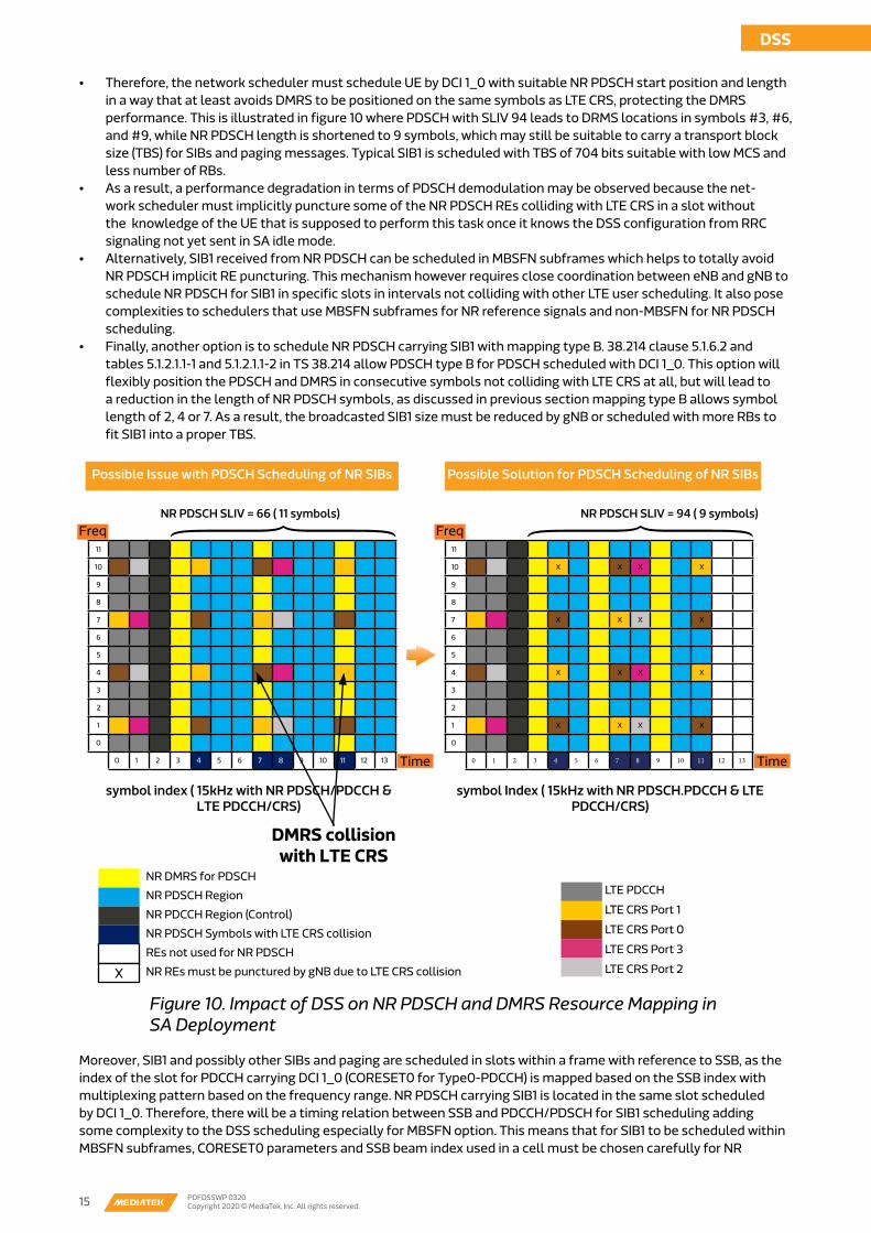
• Those tables allow different ranges for PDSCH start position and length and hence it means DMRS (with 3 sym-bols according to the explanation in the paragraph above) can be mapped to symbols that can very well conflict with LTE CRS as shown in figure 10. In these tables however, only few entries allow PDSCH to start from symbol #3 in a slot (to accommodate LTE PDCCH and NR PDCCH in symbols #0 to #2) with a suitable PDSCH length that can carry SIB messages (here we consider length 9 or 11 as suitable for system information). Figure 10 shows the issue raised by using PDSCH with SLIV = 66 (11 symbols starting at symbol #3) when scheduling SIB1 (or other SIBs and paging), as a result, DMRS will be located in symbols #3, #7 and #11 (UE cannot shift symbol #11 to #12 as it is not aware of CRS rate matching in idle mode) which coincide with LTE CRS. UE cannot perform NR PDSCH rate matching with CRS in idle mode prior to receiving SIB1 due to being unaware of DSS operation through dedicated signaling messages just yet. A solution is to reduce the length of NR PDSCH by using SLIV 94 (9 symbols starting at symbol #3) to allow DMRS to be located away from LTE CRS symbols, as shown in figure 10.
Minimum system information (MSI)
Master Information Block (MIB)
Carrier parameter and System
Frame Timing
SIB-1, Including info to Decode OSI and Paging
SIB-2, SIB-3, ...SIB-9, etc...
Remaining (RMSI)
DSS
14 PDFDSSWP 0320Copyright 2020 © MediaTek, Inc. All rights reserved. 15 PDFDSSWP 0320
Copyright 2020 © MediaTek, Inc. All rights reserved.
DSS
Figure 10. Impact of DSS on NR PDSCH and DMRS Resource Mapping in SA Deployment
• Therefore, the network scheduler must schedule UE by DCI 1_0 with suitable NR PDSCH start position and length in a way that at least avoids DMRS to be positioned on the same symbols as LTE CRS, protecting the DMRS performance. This is illustrated in figure 10 where PDSCH with SLIV 94 leads to DRMS locations in symbols #3, #6, and #9, while NR PDSCH length is shortened to 9 symbols, which may still be suitable to carry a transport block size (TBS) for SIBs and paging messages. Typical SIB1 is scheduled with TBS of 704 bits suitable with low MCS and less number of RBs.
• As a result, a performance degradation in terms of PDSCH demodulation may be observed because the net-work scheduler must implicitly puncture some of the NR PDSCH REs colliding with LTE CRS in a slot without the knowledge of the UE that is supposed to perform this task once it knows the DSS configuration from RRC signaling not yet sent in SA idle mode.
• Alternatively, SIB1 received from NR PDSCH can be scheduled in MBSFN subframes which helps to totally avoid NR PDSCH implicit RE puncturing. This mechanism however requires close coordination between eNB and gNB to schedule NR PDSCH for SIB1 in specific slots in intervals not colliding with other LTE user scheduling. It also pose complexities to schedulers that use MBSFN subframes for NR reference signals and non-MBSFN for NR PDSCH scheduling.
• Finally, another option is to schedule NR PDSCH carrying SIB1 with mapping type B. 38.214 clause 5.1.6.2 and tables 5.1.2.1.1-1 and 5.1.2.1.1-2 in TS 38.214 allow PDSCH type B for PDSCH scheduled with DCI 1_0. This option will flexibly position the PDSCH and DMRS in consecutive symbols not colliding with LTE CRS at all, but will lead to a reduction in the length of NR PDSCH symbols, as discussed in previous section mapping type B allows symbol length of 2, 4 or 7. As a result, the broadcasted SIB1 size must be reduced by gNB or scheduled with more RBs to fit SIB1 into a proper TBS.
Moreover, SIB1 and possibly other SIBs and paging are scheduled in slots within a frame with reference to SSB, as the index of the slot for PDCCH carrying DCI 1_0 (CORESET0 for Type0-PDCCH) is mapped based on the SSB index with multiplexing pattern based on the frequency range. NR PDSCH carrying SIB1 is located in the same slot scheduled by DCI 1_0. Therefore, there will be a timing relation between SSB and PDCCH/PDSCH for SIB1 scheduling adding some complexity to the DSS scheduling especially for MBSFN option. This means that for SIB1 to be scheduled within MBSFN subframes, CORESET0 parameters and SSB beam index used in a cell must be chosen carefully for NR
NR DMRS for PDSCH
NR PDSCH Region
NR PDCCH Region (Control)
NR PDSCH Symbols with LTE CRS collision
REs not used for NR PDSCH
NR REs must be punctured by gNB due to LTE CRS collision
LTE PDCCH
LTE CRS Port 1
LTE CRS Port 0
LTE CRS Port 3
LTE CRS Port 2
11
10
9
8
7
6
5
4
3
2
1
0
0 1 2 3 4 5 6 7 8 9 10 11 12 13
11
10 X X X X
9
8
7 X X X X
6
5
4 X X X X
3
2
1 X X X X
0
0 1 2 3 4 5 6 7 8 9 10 11 12 13
Possible Issue with PDSCH Scheduling of NR SIBs Possible Solution for PDSCH Scheduling of NR SIBs
NR PDSCH SLIV = 66 ( 11 symbols)
symbol index ( 15kHz with NR PDSCH/PDCCH & LTE PDCCH/CRS)
symbol Index ( 15kHz with NR PDSCH.PDCCH & LTE PDCCH/CRS)
NR PDSCH SLIV = 94 ( 9 symbols)
DMRS collision with LTE CRS
FreqFreq
TimeTime
X

DSS
16 PDFDSSWP 0320Copyright 2020 © MediaTek, Inc. All rights reserved.
PDCCH/PDSCH to fall into MBSFN subframes which would be muted for the LTE users at the time. For each SSB beam index, the SIB1 monitoring occasions are shown in table 5. In table 5, the relation between SSB beam index and PDCCH monitoring occasion slots (two consecutive slots are possible) is shown for SCS of 15 kHz for both PDCCH and SSB. This is based on TS 38.213 table 13-11 (FR1), where search space possibly used are 11, 13, and 15 because they are the ones that yield to PDCCH starting from symbol #2 in DSS. There will be extra MBSFN subframes carrying PDCCH, and arrangements must be done between eNB and gNB to fit this timing relation at a slot level not to impact LTE users.
Uplink scheduling for DSS is not expected to have less impact than downlink because most bands that are assumed to be utilized for DSS are FDD, thus, the uplink and downlink will be allocated on a separate spectrum in the same band. Different RB pairs are used by NR PUCCH for LTE and NR as well as different time/frequency location for LTE and NR PRACH. Another factor is less heavy traffic that is commonly observed in the uplink so overall the handling of the uplink traffic in DSS operation should be smooth. The main area that must be taken into account is 7.5 kHz frequency shift required to be supported. In case 15 kHz SCS is used both in NR and LTE, NR carrier will not exactly map on the same frequency grid as LTE one. The difference between NR and LTE uplink subcarrier mapping will be around 7.5 kHz. If not mitigated, it will cause inter-carrier interference due to non-orthogonal subcarriers of LTE and NR. To handle this situation, a 7.5 kHz frequency shift was introduced and it is a mandatory feature for all DSS deployments.
Although DSS provides the flexibility of spectrum usage for different radio technologies, it is obvious that the achievable maximum NR throughput will decrease due to overheads of LTE signals compared to NR cells deployed without DSS of the same bandwidth. MediaTek extensively simulated various scenarios to estimate the impacts of DSS on the downlink throughput. To perform that we have developed tools that take into account different network settings and conditions. These are general assumptions to be considered:• NR PDSCH Type A length reduces to 11 symbols from 13 symbols due to LTE PDCCH presence in the beginning of
the slot.• LTE CRS rate matching in symbols where CRS REs are transmitted. The network scheduler reduces the scheduled
MCS for NR PDSCH, to keep an effective code rate <0.95 within a slot (as stated in 3GPP TS 38.214 clause 5.1.3).• The simulations in this section focus on the impact to NR PDSCH data rate within non-MBSFN LTE subframe.• The simulations do not consider that LTE users are scheduled in parallel (assume impact of LTE PDCCH and CRS,
excluding LTE PDSCH), thus calculating the peak NR throughput impact of DSS representing the best case scenario for NR scheduling.
• NR UE is scheduled with the maximum number of RBs in 20 MHz bandwidth with 4 MIMO layers and 256QAM MCS table.
Table 5. NR PDCCH Monitoring Occasions for Type0-PDCCH in Relation to SSB Index for FR1 15 kHz SCS
SSB Index SSB Slot # Search Space Index in Table 13-11 (38.213)
Starting PDCCH Slot # (n0)
Ending PDCCH Slot #
0 0 11 0 1
1 0 11 1 2
2 1 11 2 3
3 1 11 3 4
0 0 13 2 3
1 0 13 3 4
2 1 13 4 5
3 1 13 5 6
0 0 15 5 6
1 0 15 6 7
2 1 15 7 8
3 1 15 8 9
Uplink Scheduling during DSS Operation
Simulation Overview: Slot-level Analysis
DSS Throughput Performance Simulation

DSS
16 PDFDSSWP 0320Copyright 2020 © MediaTek, Inc. All rights reserved. 17 PDFDSSWP 0320
Copyright 2020 © MediaTek, Inc. All rights reserved.
DSS
Table 6. NR Configuration for Case #1
Case #1: NR PDCCH/PDSCH SCS=15 kHz, Without SSB
The configuration of NR for this simulation is shown in table 6. In this case, the NR throughput is evaluated in slots without any NR reference signals present other than PDSCH DMRS (DMRS is sent with two symbols occupying 24 RE per PRB in a slot).
As shown in figure 11, the DSS throughput degradation in different LTE CRS configurations is evaluated with respect to normal NR slot scheduling where 13 symbols are present for PDSCH (and PDSCH DMRS) and 1 symbol for NR PDCCH. The maximum throughput degradation that can be observed when comparing 13 NR PDSCH symbols with 11 symbols is ~20% (assuming absolutely no LTE CRS is present in a subframe, for example, when all the subframes are MBSFN based). All further degradations observed are when using the CRS rate matching concept in non-MBSFN subframes where more throughput drops as more ports are deployed on LTE side incurring more LTE CRS REs occupancy. The total throughput degradation for non-MBSFN subframes is a sum of effects of the reduction of available REs, and decreasing the maximum scheduled NR PDSCH MCS to keep the effective code rate < 0.95, as the UE performs more rate matching on those unavailable REs for NR PDSCH. Taking LTE 4x4 MIMO case as an example, an additional 11% reduction in throughput comes from performing rate matching on the top of reducing PDSCH symbols to 11, totaling the reduction to 31%.
NR Configuration
Band Group FR1
NR Bandwidth (MHz) 20
PDCCH Sub Carrier Spacing 15 kHz
MIMO Layers 4
xOverhead in PDSCH 0
Scheduler
MCS Table 256QAM
Max MCS 27
Max PRB 106
FDD Frequency Band n3
Type-A SLIV (Symbol Length, Start Symbol)
66 (11,3)
DM-RS Configuration
dmrs-DownlinkForPDSCH-MappingType A
dmrs-Type 1
dmrs-AdditionalPosition POS1
maxLength Single Symbol
# CDM Groups 2
Figure 11. Maximum NR Slot Throughput (Mbps) for Case #1
417.976
335.976327.888
303.24286.976
-20% -31%
PDSCH 13 Symbol(without DSS)
PDSCH 11Symbol+LTE CRS
RATE MATCHING (1CRS PORT )
PDSCH 11SYMBOL+LTE CRSRATE MATCHING (2
CRS PORT)
PDSH 11SYMBOL+LTE CRSRATE MATCHING (4
CRS PORT)
PDSCH 11 Symbol
Using MBSFN-based DSS(over all subframes)

DSS
18 PDFDSSWP 0320Copyright 2020 © MediaTek, Inc. All rights reserved.
There are ways to improve the NR throughput in DSS cells. If DMRS configuration is changed to use only front-loaded symbols (POS0 configuration) with 1 symbol occupying 6 REs, then less overhead to NR PDSCH. The gain from such NR overhead reduction is significant. For example for the worst case of LTE 4x4 MIMO the improvement was from 31% to 25% throughput drop (16% degradation comes from reducing PDSCH length to 11 symbols – implying the degradation by LTE PDCCH scheduling, and 9% degradation comes from LTE CRS rate matching – maximum MCS decreases to 24 to keep scheduled code rate < 0.95). Certain restrictions apply though for this method. First, the single symbol DMRS is suitable for near cell center radio conditions. The second point to take into account is that not all network vendors support a configuration where NR PDSCH can fill in the empty REs within DMRS symbols as a single symbol transmission.
The second case to compare with is the same configuration as in Case #1, but using RB-level CRS rate matching instead of RE-level. This brings 36 REs LTE CRS overhead for one and two antenna ports and 48 for four antenna ports configuration. The simulation shows a significant drop of the throughput in case RE-level rate matching is replaced with RB-level one. The comparison of these with respect to LTE configuration can be seen in figure 12. As shown, the drop is most dramatic in case of LTE four antenna port configuration as it goes from 287 Mbps to 88 Mbps. This is the reason why RB-level rate matching is not supposed to be used unless there is a task to avoid collision with LTE PSS/SSS and PBCH. RB-level rate matching can also be more challenging on the NR RF end due to the varied LTE power on different NR OFDM symbols.
In this case, NR SSB is used in the same frame where NR PDSCH is also scheduled. For this example we use the network configuration as shown in table 7. The simulation involves mapping of Type B for the slots that contain SSB as shown previously in figure 7. There is only 1 SSB beam available (band n5, Case B – refer to figure 2). LTE CRS configuration stays the same like in simulation case #1, so that it will occupy 6, 12 or 16 REs for one/two/four LTE antenna ports, respectively.
Case #2: Similar to Case #1, Adding RB-Level CRS Rate Matching
Case #3: NR PDCCH/PDSCH SCS=15 kHz, With SSB SCS=30 kHz
327.888
163.976
303.24
163.976
286.976
88.064
PDSCH 11 SYMBOLS+LTE CRS RATE
MATCHING (1 CRS PORT)
PDSCH 11 SYMBOLS+LTE CRS RATE
MATCHING (2 CRS PORT)
PDSCH 11 SYMBOLS+LTE CRS RATE
MATCHING (4 CRS PORT)
RE Level Rate Matching RB Level Rate matching
Figure 12. Maximum NR Slot Throughput (Mbps) for Case #2 – RE vs RB Level CRS Rate Matching

DSS
18 PDFDSSWP 0320Copyright 2020 © MediaTek, Inc. All rights reserved. 19 PDFDSSWP 0320
Copyright 2020 © MediaTek, Inc. All rights reserved.
DSS
Figure 13. Maximum NR Slot Throughput (Mbps) for Case #3
Table 7. NR Configuration for Case #3
NR Configuration Band Group FR1
NR Bandwidth (MHz) 20
PDCCH Sub Carrier Spacing 15 kHz
MIMO Layers 4
xOverhead in PDSCH 0
Scheduler MCS Table 256QAM
Max MCS 27
Max PRB 106
FDD Frequency Band n5
SSB Slot Type-B SLIV (Symbol Length, Start Symbol)
90 (7,6)
Non SSB Slot Type-A SLIV (Symbol Length, Start Symbol)
66 (11,3)
rbg-size Config2 (16RB per RBG)
DM-RS Configuration dmrs-DownlinkForPDSCH-MappingType A
dmrs-Type 1
dmrs-AdditionalPosition POS1
maxLength Single Symbol
# CDM Groups 2
SSB Configuration ssb-periodicityServingCell (msec) 20
Frequency f ≤ 3 GHz
The throughput degradation for this case is shown in figure 13 in comparison with SSB-free slots. The decrease in NR downlink throughput observed is minimal; dropping in average of 4%. This means that inserting SSB does not have a significant impact on the overall throughput.
There is a way to improve NR throughput in case of SSB at 30 kHz present – some network vendors allow to enable rate matching at RB level between PDSCH and SSB. This means that there will be more RBs available for NR PDSCH in slots where SSB is transmitted (every SSB periodicity of 20 msec in this case where SSB always occupy 20 RBs). This will improve RB utilization in slots with SSB yet there is a drawback related to this method. Puncturing SSB may affect SSB performance itself. Since the gain is not that huge (3% degradation vs. 4% without SSB rate matching) this option may not be the most effective way to improve the DSS throughput.
327.888
314.977
303.24
291.35286.976
275.599
PDSCH 11 SYMBOLS (NON SSB SLOTS) +7SYMBOLS (SSB SLOTS)+ LTE CRS RATE
MATCHING ( 1 CRS PORT)
PDSCH 11 SYMBOLS (NON SSB SLOTS) +7SYMBOLS (SSB SLOTS)+ LTE CRS RATE
MATCHING ( 2 CRS PORT)
PDSCH 11 SYMBOLS (NON SSB SLOTS) +7SYMBOLS (SSB SLOTS)+ LTE CRS RATE
MATCHING ( 4 CRS PORT)
Without SSB With SSB

DSS
20 PDFDSSWP 0320Copyright 2020 © MediaTek, Inc. All rights reserved.
Case #4: Similar to Case #2, Adding CSI-RS and TRSReference Signals
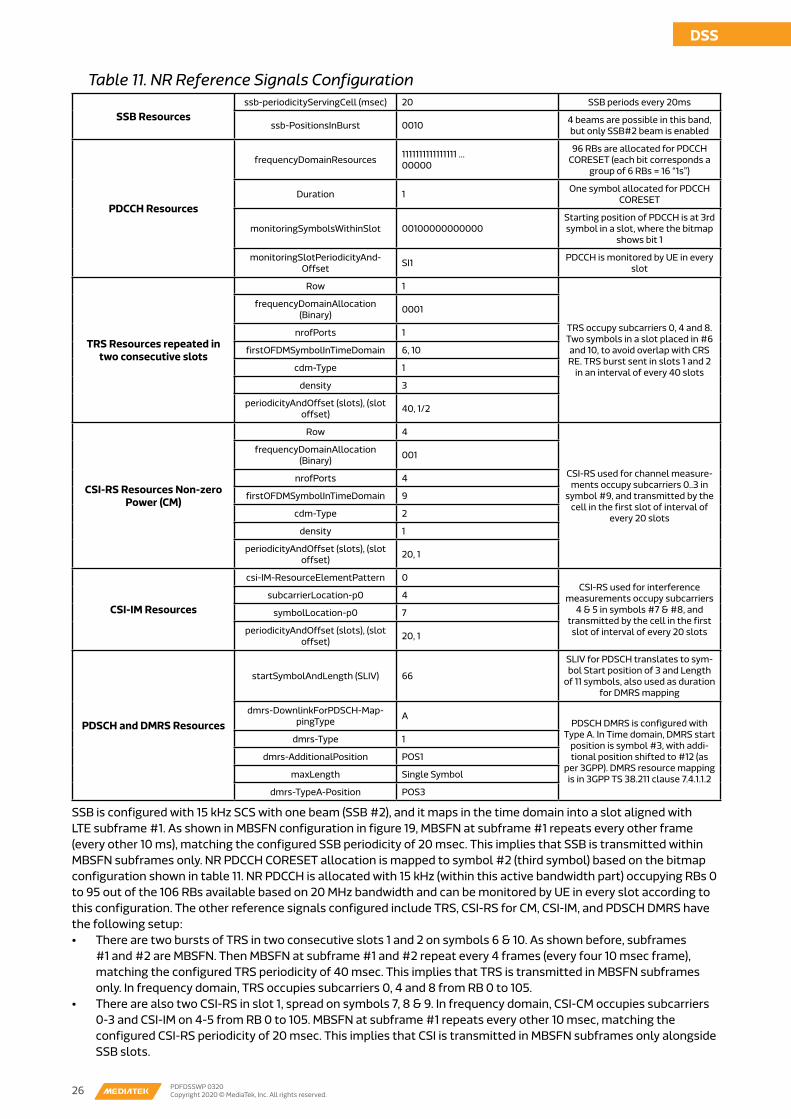
In all previous examples, we did not take all NR reference signals into account. Taking the configuration from simulation case #3, we have added CSI-RS (Channel State Information Reference Signal), CSI-IM (CSI for Interference Measurement) and TRS (Tracking Reference Signal) into the picture to see what will be the resulting throughput. This is an end-to-end representation of peak NR user throughput in DSS-enabled network (in case of absence of any LTE traffic of course, except for the presence of LTE CRS that are with always-on transmission). The corresponding configurations are given in table 8. Note that it is assumed that all NR PDSCH rate matching with SSB, CSI-RS and TRS are disabled.
As shown in figure 14, the scenario with four LTE antenna ports leads to 34% degradation if compared to non-DSS NR deployment at maximum throughput, which is an end-to-end downlink throughput impact coming from both NR PDSCH symbol reduction and LTE CRS rate matching while using all NR channels for data, control and reference signals. This means that inserting all other channels in DL scheduling, NR throughput degradation baseline based on such configuration in average is 30% across different CRS configuration.
Table 8. NR Configuration for Reference Signals for Case #4
TRS Resources repeated in two con-secutive slots
Row 1
frequencyDomainAllocation (Binary) 0100 (occupy subcarriers2,6 and 10)
nrofPorts 1
firstOFDMSymbolInTimeDomain 6, 10 (two symbols in a slot) to avoid overlap with CRS RE
firstOFDMSymbolInTimeDomain2 Absent
cdm-Type 1
density 3
periodicityAndOffset (slots) 20
CSI-RS Resources Non-zero Power (CM)
Row 4
frequencyDomainAllocation (Binary) 010
nrofPorts 4
firstOFDMSymbolInTimeDomain 13
firstOFDMSymbolInTimeDomain2 Absent
cdm-Type 2
density 1
periodicityAndOffset (slots) 40
CSI-IM Resources
csi-IM-ResourceElementPattern 1
subcarrierLocation-p1 4
symbolLocation-p1 12
periodicityAndOffset (slots) 40

DSS
20 PDFDSSWP 0320Copyright 2020 © MediaTek, Inc. All rights reserved. 21 PDFDSSWP 0320
Copyright 2020 © MediaTek, Inc. All rights reserved.
DSS
Table 9. Baseline LTE Throughput Reduction in DSS Cell
417.976394.015
327.888304.738 303.240
273.949286.976
260.224
PDSCH 13 SYMBOLS (WITHOUT DSS)
PDSCH 11 SYMBOLS( NON SSB SLOTS) +7 SYMBOLS
( SSB SLOTS)+LTE CRS RATEMATCHING ( 1 CRS PORT)
PDSCH 11 SYMBOLS( NON SSB SLOTS) +7 SYMBOLS
( SSB SLOTS)+LTE CRS RATEMATCHING ( 2 CRS PORT)
PDSCH 11 SYMBOLS( NON SSB SLOTS) +7 SYMBOLS
( SSB SLOTS)+LTE CRS RATEMATCHING ( 4 CRS PORT)
Only PDSC/PDCCH All NR Channels
-23%-34%
Figure 14. Maximum NR Slot Throughput (Mbps) for Case #4
NR PDSCH rate matching with CSI-RS and TRS can also give more improvements. However, it depends how many slots become available for NR within one frame shared with LTE. In such cases, network scheduler may choose to put all NR reference signals in same slot where available symbols for PDSCH become limited. This is to be discussed in details in next section.
NR UE is aware of LTE presence in the cell where DSS is enabled. But as LTE users are unaware of the presence of NR in the DSS cell, there always must be an impact on the throughput caused at least by NR synchronization channels. The baseline impact of inserting SSB in the slot for the UE to synchronize to NR cell in connected mode to the LTE single UE throughput will be around 5-10% after enabling DSS using MBSFN or non-MBSFN DSS deployment. With SSB burst period at 20 msec and SSB Measurement Time Configuration (SMTC) of 20 msec, SSB burst duration is 0.5 msec~2 msec for different configurations of frequency below 3 GHz. If four 15 kHz SSBs are used, two slots will be occupied. For 30 kHz SSB there will be two slots with PDCCH/PDSCH SCS of 15 kHz, regardless of the number of SSB beams, as shown in figure 2 and 3. The summary of the baseline LTE throughput reduction due to SSB presence in DSS cells is shown in table 9.
LTE Single User Throughput Impact
NR SSB in ≤ 3GHz, with NR PDCCH/PDSCH SCS of 15kHz
LTE Throughput Reduction in MBSFN LTE Throughput Reduction in Non-MBSFN
LTE CRS port <4 LTE CRS port=4LTE CRS port <4 LTE CRS port=4
SCS 15kHz Case A 10% (up to 4 SSB beams)
10% (up to 4 SSB beams)
NA (No SSB possible)
NA (No SSB possible)
SCS 30kHz Case B 5% (up to 4 SSB beams)
5% (up to 4 SSB beams)
5% (up to 2 SSB beams)
5% (up to 1 SSB beam)
SCS 30kHz Case C 5% (up to 3 SSB beams)
5% (up to 3 SSB beams)
5% (up to 1 SSB beam)
NA (No SSB possible)

DSS
22 PDFDSSWP 0320Copyright 2020 © MediaTek, Inc. All rights reserved.
Possible Phases of DSS Deployment: Frame-level Analysis
DSS Scheduler ConfigurationsDSS Scheduler Configurations
DSS Scheduling and Cell Resource Coordination in Mixed LTE/NR Traffic Scenarios
The previous section was based on the assumption that there is no LTE traffic in the DSS cell. Obviously this scenario as not realistic especially with respect to the fact that at least in initial stages of DSS deployment major traffic load will still be generated by 4G users. This early stage will be characterized by DSS deployed mainly for coverage enhancements. Figure 15 illustrates the possible deployment stages of DSS feature where both MBSFN-based DSS and non-MBSFN based CRS rate matching as discussed in the previous sections (MBSFN for SSB, TRS, CSI-RS, non-MBSFN for data traffic). In both cases either gNB or eNB can trigger Cell Resource Coordination at a frame level with some granularity that can ensure fair share in scheduling across LTE and NR users. The impact on LTE user throughput will be governed by using TDM subframe patterns for sharing between LTE and NR within a frame.
In later DSS phase shown in figure 15, when NR traffic significantly grows would require feature optimization. This includes DSS NR carrier aggregation, optimized rate matching in a mixed type of NR slots containing NR PDSCH and other NR reference signals, using Release 16 type B mapping extension (up to 10 symbols length), TDM+FDM resource split between LTE and NR, FR1 TDD bands for DSS operation and faster downlink and uplink resource allocation. DSS optimizations may be influenced by NR standalone or non-standalone deployment.
At the subframe level, the network scheduler can coordinate cell resources between LTE and NR users in TDM (Time Division Multiplexing) and/or FDM (Frequency Division Multiplexing) fashions during LTE/NR spectrum sharing scheduling. Both options are shown in figure 16.
Figure 15. Possible Phases of DSS Deployment
Freq (RE/RB)
Time
LTE/NR TDM
MBSFN-based DSS CRS Rate Matching DSS DSS Optimization
DSS for NSA in FR1 FDD with NR
SCS of 15kHz
DSS for NSA, SA, SA+NSA in FR1
FDD with NR SCS of 15kHz
DSS for NSA, SA, SA+NSA in FR1 FDD and/or TDD
NR DL Data Transmission in LTE MBSFN subframesReduce impact to LTE by using TDM sub-frame patterns for sharing between LTE and NR within a frame.Both the gNB and the eNB can trigger cell resource coordination procedure over X2
NR DL Data Transmission in LTE Normal SubframesTo avoid NR complexity, posible to use LTE MBSFN subframes for SSB, CSI-RS, TRSUsing LTE TDM subframes with patterns of sharingBoth the gNB and the eNB can triggger Cell Resource Coordination procedure over X2 or Xn
DSS for NR Carrier AggregationOptimized Rate matching with a mixed type of NR slots allows for FDM scheduling to be possibleTDM+FDM resource split in DL between LTE and NRFR1 TDD can be extended for DSS operationFaster DL and UL resources allocation
NR Traffic is low and FDD cell mainly needed for NR coverage
NR Traffic gets higher and FDD cell needed for NR coverage and throughput
Note#1

DSS
22 PDFDSSWP 0320Copyright 2020 © MediaTek, Inc. All rights reserved. 23 PDFDSSWP 0320
Copyright 2020 © MediaTek, Inc. All rights reserved.
DSS
Figure 16. TDM and FDM DSSLTE PDCCH
LTE CRS
LTE PDSCH
NR PDCCH
NR PDSCH
LTE/NR FDM
Each of these implementations has its own pros and cons:• For TDM pattern – as seen in the area of Note #1: There are wasted RB resource to transmit LTE PDCCH if no LTE
PDSCH is scheduled in the slot, which requires coordination between LTE and NR in terms of TDM patterns per subframes/slots.
• For FDM pattern – as seen in the area of Note #2: Maximum assigned LTE RB is bounded by NR PDCCH configuration or by NR PDSCH SLIV (without NR PDCCH), because LTE PDSCH must be scheduled right after LTE PDCCH in time domain.
However, as noted earlier, the initial stages of DSS deployment will see TDM scheduling mainly used with a mix between MBSFN and non-MBSFN patterns. Table 10 represents an example of TDM patterns (LTE-to-NR ratio at subframe level within a frame). The ratio in scheduling between LTE and NR with patterns shown as examples in table 10 controls the impact on LTE throughput and ensures NR performance based on user traffic load from each technology.
Table 10. Example of TDM Patterns for DSS Operation in a Cell
DSS Type
4G:5G TDM Ratio
Examples of TDM Patterns: Subframe in one frame (1ms subframe = 10ms frame)
0 1 2 3 4 5 6 7 8 9
MBSFN-based
8:2 LTE MBSFN MBSFN LTE LTE LTE LTE LTE LTE LTE
5:5 LTE MBSFN MBSFN LTE LTE LTE MBSFN MBSFN MBSFN LTE
Rate Match-
ing
Variable NR/LTE NR/LTE NR/LTE NR/LTE NR/LTE NR/LTE NR/LTE NR/LTE NR/LTE NR/LTE
For MBSFN case in table 10, for pre-Release 14 configuration, the network can configure FDD MBSFN at most at subframes #1, #2, #3, #6, #7, #8 within each radio frame. Therefore, the maximum TDM pattern can be set to be 4:6 (4G:5G). CRS rate matching takes place in non-MBSFN subframes which are absolutely flexible up to network scheduler as we are matching around LTE CRS when the UE is made aware of the CRS RE locations. A mix between MBSFN (e.g. for NR reference signals) and CRS Rate Matching (e.g. for data) is possible while maintaining the 4G:5G TDM ratio on the normal subframes. Also keep in mind that in some instances, a couple of LTE subframes in a frame must be used for NR reference signals (e.g. SSB and TRS) depending on the periodicity of such signals.
We can now take examples of DSS scheduling including the RRC configuration for NR UE, the physical layer resource mapping in time-frequency domain and the overall peak downlink throughput expected in such configuration. As depicted in figure 17 on the leftmost side, the UE sends its NR capability, which indicates the UE support for the main DSS features discussed before in table 3. In the UE capability, most of the features related to DSS are under physical layer parameters while the rateMatchingLTE-CRS is indicated per band (here it is supported by UE on n3, and can be possibly extended to other bands based on UE capability). In figure 17 on the rightmost side, NR SCG cell is then added by rrcConnectionReconfiguration message in band n3 NSA with 20 MHz (106 RBs). SSB is configured with 15 kHz, and BWP part is configured with 15 kHz, which applies to NR PDCCH and PDSCH under this Active BWP Id=0 (generally, the SCS indicated in the active BWP apply to all NR channels and reference signals unless explicitly configured elsewhere in the RRC configuration).
Note#2

DSS
24 PDFDSSWP 0320Copyright 2020 © MediaTek, Inc. All rights reserved.
Figure 17. General NR Configuration in RRC Connection Reconfiguration Message, Configuring Secondary Cell Group (SCG)
In the same rrcConnectionReconfiguration, the LTE CRS and MBSFN pattern for DSS is configured according to figure 18.• LTE cell in band 3 is configured with center subcarrier location of 636 which is an offset from NR PointA.• LTE bandwidth is 100 RBs = 20 MHz. • Number of LTE ports is 4, which implies this is LTE 4x4 MIMO with four antenna ports. • V-shift allows the UE to know the RE location of the LTE CRS for rate matching on the collocated LTE cell. Instead
of knowing LTE PCI, with V-shift UE knows the LTE CRS RE locations in frequency and time domain as shown in figure 18 mapping. The details of LTE CRS mapping to resource elements is in 3GPP TS 36.211 clause 6.10.1.2.
Figure 18. LTE Band & CRS Configurations inside NR Cell for DSS, configured to UE in rrcConnectionReconfiguration Message
LTE PDCCHLTE CRS Port 1LTE CRS Port 0LTE CRS Port 3LTE CRS Port 2
11
10
9
8
7
6
5
4
3
2
1
0
0 1 2 3 4 5 6 7 8 9 10 11 12 13
Symbol Index (15kHz with NR PDSCH/PDCCH & LTE PDCCH/CRS)
1st LTE slot 2st LTE slot
0 1 2 3 4 5 6 0 1 2 3 4 5 6
spCellConfigCommon...Ite-CRS-ToMatchAround setup crrierFreqDL = 636 carrierBandwidthDL = n100MBSFN mbsfn-SubframeConfigListConfiguration Item-0 EUTRA-MBSFN-SubframeConfig radioframeAllocationPeriod = n4 radioframeAllocationOffset = 0 subframeAllocation1 fourFrames = ‘110000000000100000000000’B nrofCRS-Ports = n4 v-Shift =n4
UE-NR Capability phy-Parameters phy-ParametersCommon . . pdsch-MappingTypeA: supported (0) pdsch-MappingTypeB: supported (0) ... phy-Parameters FRX-Diff . . multipleCORESET: supported (0) phy-ParameterFR1 . pdcchMonitoringSingleOccasion: supported (0)rf-Parameters ... BandNR bandNR: 3 . . rateMatchingLTE-CRS: supported (0) ... featureSetsDownlink-v1540: 2 items FeatureSetDownlink-v1540 . . additionalDMRS-DL-Alt: supported (0)
rrcConnectionReconfiguration : spCellConfig physCellId = 50 downlinkConfigCommon freqencyInfoDL absoluteFrequencySSB = 370048 frequencyBandList Item-0 FreqBandIndicatorNR = 3 absoluteFrequencyPointA = 366592 scs-SpecificCarrierList Item-0 SCS-SpecificCarrier offsetToCarrier = 0 subcarrierSpacing = kHz15 CarrierBandwidth = 106 ....
ssb-PostionsInBurst shortBitmap = “0010’B ssb-periodicityServingCell = ms20 subcarrierSpacing = kHz15 ....
initialDownlinkBWP genericParameter locationAndBandwith = 28875 subcarrierSpacing = kHz15 firstActiveDownlinkBWP-Id = 0
Freq (REs)
Time
>

DSS
24 PDFDSSWP 0320Copyright 2020 © MediaTek, Inc. All rights reserved. 25 PDFDSSWP 0320
Copyright 2020 © MediaTek, Inc. All rights reserved.
DSS
Figure 19. MBSFN Subframes Configuration for DSS Operation
The MBSFN configuration is interpreted as follows:• Radio frames that contain MBSFN subframes occur when equation SFN mod radioFrameAllocationPeriod = • radioFrameAllocationOffset is satisfied. • Only one MBSFN pattern allocated under subframeAllocation1.• Parameter fourFrames is a bitmap applying to MBSFN subframes #1, #2, #3, #6, #7, #8 in the sequence of four
radio-frames. In this case the value ‘110000000000100000000000’ indicates subframe allocation as shown in Figure 19.
• Instead of fourFrames, the network can choose another option such as oneFrame, which is a bitmap allocation applies to MBSFN subframes #1, #2, #3, #6, #7, and #8 in the sequence of one radio-frame.
• If the cell is configured with additional MBSFN pattern, for example for Rel-14, then subframeAllocation2 can be used which is optionally applied to MBSFN subframes #4 and #9 in the sequence of one or four radio-frames (for LTE FDD).
The other NR reference signals parameters are highlighted in table 11. The UE receives the configuration for each reference signal in rrcConnectionReconfiguration and apply the parameters to know the time-frequency resource mapping. As observed, the majority of these NR parameters are set as bitmaps or follow specific mapping tables (e.g. in TS 38.211 or TS 38.214) in order to allow for the flexibility of resource allocation across all NR signals and channels.
radioframeAlloca-tionPeriod
4
radioframeAlloca-tionOffset
0
Frame Number Frame Contains MBSFN Subframes
0 Yes
1 No
2 No
3 No
4 Yes
5 No
6 No
7 No
8 Yes
9 No
MBSFN Subframe
Normal Subframe
MBSFN Allocation in 4 consecutive frames
fourFrames = ‘110000 000000 100000 000000’
Subframes #1, #2, #3, #6, #7, and #8 are allocted to MBSFN if their bitmap is set to “1” in the fourFrame over the period of four frame, and then the pattern repeats where it was left, based onthe frame number in the table for frames satisfying:SFN mod radioFrameAllocationPeriod = radioFrameAllocationOffsetBecause fourFrames is used then starting from frame 0 would follow the fourFrames pattern and then repeats again at frame 4. If onFrame is used, then table applies per each frame with a subframe pattern set by the bitmap
No MBSFN No MBSFN
Only Subframe #1 in 3rd frame
LTE Radio Frames which contains MBSFN subframes based on this Network Configuration
LTE Radio Frame LTE Radio Frame LTE Radio Frame LTE Radio Frame LTE Radio Frame
0 1 2 3 4
0 1 2 3 4 5 6 7 8 9 0 1 2 3 4 5 6 7 8 9 0 1 2 3 4 5 6 7 8 9 0 1 2 3 4 5 6 7 8 9 0 1 2 3 4 5 6 7 8 9
Subf
ram
e#Fr
ame#
DSS
26 PDFDSSWP 0320Copyright 2020 © MediaTek, Inc. All rights reserved.
SSB Resourcesssb-periodicityServingCell (msec) 20 SSB periods every 20ms
ssb-PositionsInBurst 0010 4 beams are possible in this band, but only SSB#2 beam is enabled
PDCCH Resources
frequencyDomainResources 1111111111111111 … 00000
96 RBs are allocated for PDCCH CORESET (each bit corresponds a
group of 6 RBs = 16 “1s”)
Duration 1 One symbol allocated for PDCCH CORESET
monitoringSymbolsWithinSlot 00100000000000Starting position of PDCCH is at 3rd symbol in a slot, where the bitmap
shows bit 1
monitoringSlotPeriodicityAnd-Offset SI1 PDCCH is monitored by UE in every
slot
TRS Resources repeated in two consecutive slots
Row 1
TRS occupy subcarriers 0, 4 and 8. Two symbols in a slot placed in #6 and 10, to avoid overlap with CRS RE. TRS burst sent in slots 1 and 2
in an interval of every 40 slots
frequencyDomainAllocation (Binary) 0001
nrofPorts 1
firstOFDMSymbolInTimeDomain 6, 10
cdm-Type 1
density 3
periodicityAndOffset (slots), (slot offset) 40, 1/2
CSI-RS Resources Non-zero Power (CM)
Row 4
CSI-RS used for channel measure-ments occupy subcarriers 0..3 in
symbol #9, and transmitted by the cell in the first slot of interval of
every 20 slots
frequencyDomainAllocation (Binary) 001
nrofPorts 4
firstOFDMSymbolInTimeDomain 9
cdm-Type 2
density 1
periodicityAndOffset (slots), (slot offset) 20, 1
CSI-IM Resources
csi-IM-ResourceElementPattern 0CSI-RS used for interference
measurements occupy subcarriers 4 & 5 in symbols #7 & #8, and
transmitted by the cell in the first slot of interval of every 20 slots
subcarrierLocation-p0 4
symbolLocation-p0 7
periodicityAndOffset (slots), (slot offset) 20, 1
PDSCH and DMRS Resources
startSymbolAndLength (SLIV) 66
SLIV for PDSCH translates to sym-bol Start position of 3 and Length
of 11 symbols, also used as duration for DMRS mapping
dmrs-DownlinkForPDSCH-Map-pingType A
PDSCH DMRS is configured with Type A. In Time domain, DMRS start
position is symbol #3, with addi-tional position shifted to #12 (as
per 3GPP). DMRS resource mapping is in 3GPP TS 38.211 clause 7.4.1.1.2
dmrs-Type 1
dmrs-AdditionalPosition POS1
maxLength Single Symbol
dmrs-TypeA-Position POS3
Table 11. NR Reference Signals Configuration
SSB is configured with 15 kHz SCS with one beam (SSB #2), and it maps in the time domain into a slot aligned with LTE subframe #1. As shown in MBSFN configuration in figure 19, MBSFN at subframe #1 repeats every other frame (every other 10 ms), matching the configured SSB periodicity of 20 msec. This implies that SSB is transmitted within MBSFN subframes only. NR PDCCH CORESET allocation is mapped to symbol #2 (third symbol) based on the bitmap configuration shown in table 11. NR PDCCH is allocated with 15 kHz (within this active bandwidth part) occupying RBs 0 to 95 out of the 106 RBs available based on 20 MHz bandwidth and can be monitored by UE in every slot according to this configuration. The other reference signals configured include TRS, CSI-RS for CM, CSI-IM, and PDSCH DMRS have the following setup:• There are two bursts of TRS in two consecutive slots 1 and 2 on symbols 6 & 10. As shown before, subframes
#1 and #2 are MBSFN. Then MBSFN at subframe #1 and #2 repeat every 4 frames (every four 10 msec frame), matching the configured TRS periodicity of 40 msec. This implies that TRS is transmitted in MBSFN subframes only. In frequency domain, TRS occupies subcarriers 0, 4 and 8 from RB 0 to 105.
• There are also two CSI-RS in slot 1, spread on symbols 7, 8 & 9. In frequency domain, CSI-CM occupies subcarriers 0-3 and CSI-IM on 4-5 from RB 0 to 105. MBSFN at subframe #1 repeats every other 10 msec, matching the configured CSI-RS periodicity of 20 msec. This implies that CSI is transmitted in MBSFN subframes only alongside SSB slots.

DSS
26 PDFDSSWP 0320Copyright 2020 © MediaTek, Inc. All rights reserved. 27 PDFDSSWP 0320
Copyright 2020 © MediaTek, Inc. All rights reserved.
DSS
• As the network configures the UE with PDSCH mapping Type A and SLIV = 66 (in this configuration, only one SLIV is scheduled to the UE in RRC message), then PDSCH Start position is symbol #3, and the length is 11 symbols. According to PDSCH DMRS resource mapping TS 38.211, the time domain allocation for DMRS is in two symbols (dmrs-AdditionalPosition = POS1) and is originally defined in symbols #3 and #11. But since symbol #11 overlaps with LTE CRS, and UE supports additionalDMRS-DL-Alt as shown in figure 17, then the additional position is shifted to symbol #12. In frequency domain, dmrs-Type = 1, and assuming the NR PDCCH schedules the UE with two CDM groups, then DMRS occupy 12 REs/symbol (24 REs over two DMRS symbols). This leaves a total of 108 REs (12REs*11 symbols – 24 DMRS overhead) for PDSCH. From there, the UE can determine the Transport Block Size (TBS) whenever the UE is scheduled in a slot for NR data transmission.
The overall view of NR reference signals that are transmitted in MBSFN subframes is shown in figure 20.
LTE Radio Frames which contains MBSFN subframes based on this Network Configuration
LTE Radio Frame LTE Radio Frame LTE Radio Frame LTE Radio Frame LTE Radio Frame
0 1 2 3 4
0 1 2 3 4 5 6 7 8 9 0 1 2 3 4 5 6 7 8 9 0 1 2 3 4 5 6 7 8 9 0 1 2 3 4 5 6 7 8 9 0 1 2 3 4 5 6 7 8 9
Subf
ram
e#Fr
ame#
Normal Subframes that can flexibly shared between LTE and NR PDSCH
MBSFN Subframe with SSB+CSI-RS+TRS 1st Slot MBSFN Subframe with TRS 2nd slot
MBSFN Subframe with SSB+CSI-RS
11
10
9
8
7
6
5
4
3
2
1
0
0 1 2 3 4 5 6 7 8 9 10 11 12 13
Symbol Index (15kHz with NR PDSCH/PDCCH & LTE PDCCH/CRS)
SSB#2
4 LTE CRS ports
11
10
9
8
7
6
5
4
3
2
1
0
0 1 2 3 4 5 6 7 8 9 10 11 12 13
Symbol Index (15kHz with NR PDSCH/PDCCH & LTE PDCCH/CRS)
TRSLTE PDCCH
11
10
9
8
7
6
5
4
3
2
1
0
0 1 2 3 4 5 6 7 8 9 10 11 12 13
Symbol Index (15kHz with NR PDSCH/PDCCH & LTE PDCCH/CRS)
CSI-IM
CSI-RS for CM
Figure 20. Overall View of NR and LTE Reference Signals in Time-Frequency
Freq
TimeTime
Time
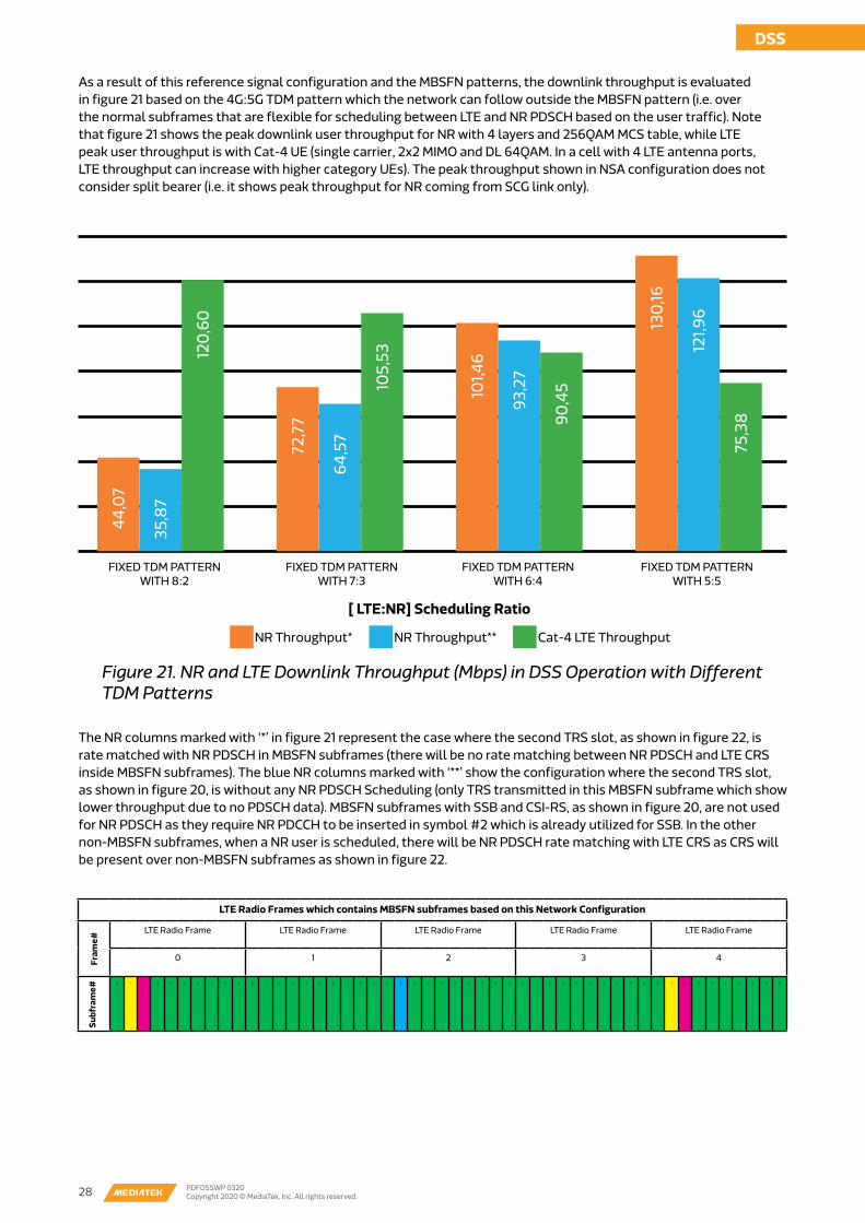
DSS
28 PDFDSSWP 0320Copyright 2020 © MediaTek, Inc. All rights reserved.
As a result of this reference signal configuration and the MBSFN patterns, the downlink throughput is evaluated in figure 21 based on the 4G:5G TDM pattern which the network can follow outside the MBSFN pattern (i.e. over the normal subframes that are flexible for scheduling between LTE and NR PDSCH based on the user traffic). Note that figure 21 shows the peak downlink user throughput for NR with 4 layers and 256QAM MCS table, while LTE peak user throughput is with Cat-4 UE (single carrier, 2x2 MIMO and DL 64QAM. In a cell with 4 LTE antenna ports, LTE throughput can increase with higher category UEs). The peak throughput shown in NSA configuration does not consider split bearer (i.e. it shows peak throughput for NR coming from SCG link only).
The NR columns marked with ‘*’ in figure 21 represent the case where the second TRS slot, as shown in figure 22, is rate matched with NR PDSCH in MBSFN subframes (there will be no rate matching between NR PDSCH and LTE CRS inside MBSFN subframes). The blue NR columns marked with ‘**’ show the configuration where the second TRS slot, as shown in figure 20, is without any NR PDSCH Scheduling (only TRS transmitted in this MBSFN subframe which show lower throughput due to no PDSCH data). MBSFN subframes with SSB and CSI-RS, as shown in figure 20, are not used for NR PDSCH as they require NR PDCCH to be inserted in symbol #2 which is already utilized for SSB. In the other non-MBSFN subframes, when a NR user is scheduled, there will be NR PDSCH rate matching with LTE CRS as CRS will be present over non-MBSFN subframes as shown in figure 22.
44,0
7
35,8
7
120,
60
72,7
7
64,5
7
105,
53
101,4
6
93,2
7
90,4
5
130,
16
121,9
6
75,3
8
FIXED TDM PATTERN WITH 8:2
FIXED TDM PATTERN WITH 7:3
FIXED TDM PATTERN WITH 6:4
FIXED TDM PATTERN WITH 5:5
[ LTE:NR] Scheduling Ratio
NR Throughput* NR Throughput** Cat-4 LTE Throughput
Figure 21. NR and LTE Downlink Throughput (Mbps) in DSS Operation with Different TDM Patterns
LTE Radio Frames which contains MBSFN subframes based on this Network Configuration
LTE Radio Frame LTE Radio Frame LTE Radio Frame LTE Radio Frame LTE Radio Frame
0 1 2 3 4
0 1 2 3 4 5 6 7 8 9 0 1 2 3 4 5 6 7 8 9 0 1 2 3 4 5 6 7 8 9 0 1 2 3 4 5 6 7 8 9 0 1 2 3 4 5 6 7 8 9
Subf
ram
e#Fr
ame#

DSS
28 PDFDSSWP 0320Copyright 2020 © MediaTek, Inc. All rights reserved. 29 PDFDSSWP 0320
Copyright 2020 © MediaTek, Inc. All rights reserved.
DSS
NR DMRS for PDSCH
NR PDSCH Region
NR PDSCH Region (Control)
NR PDSCH Symbols where REs must be rate matched with LTE CRS
NR TRS
LTE PDCCH
LTE CRS Port 1
LTE CRS Port 0
LTE CRS Port 3
LTE CRS Port 2
Normal Subframes that can be used to schedule NR PDSH applying CRS rate matching
MBSFN Subframe with TRS 2nd slot, rate matched with NR PDSCH
11
10
9
8
7
6
5
4
3
2
1
0
0 1 2 3 4 5 6 7 8 9 10 11 12 13
Symbol Index ( 15 kHz with NR PDSCH/PDCCH & LTE PD-CCH/CRS)
11
10
9
8
7
6
5
4
3
2
1
0
0 1 2 3 4 5 6 7 8 9 10 11 12 13
Symbol Index ( 15 kHz with NR PDSCH/PDCCH & LTE PD-CCH/CRS)
Figure 22. NR PDSCH Scheduling with LTE CRS Rate Matching in non-MBSFN subframes
Summary and ConclusionDSS is a powerful and flexible feature developed by 3GPP to expedite 5G NR deployment in low bands needed for coverage without the need to re-farm the entire band for 5G. It ensures a smooth coexistence with LTE and minimizes the impact to legacy LTE devices. In this paper we show what would be an evolution from the initial stages of DSS deployment to its optimized configuration, with more enhancements expected to come in 3GPP Release 16 providing better performance and resolving some of the issues observed in the initial deployment. The baseline in the current 3GPP Release 15 is using MBSFN-based DSS to ensure NR reference signals are protected away from conflict with LTE reference signals, and CRS rate matching within normal subframes as an option to ensure data transmission coexistence in the same subframes with those for LTE users. The other concepts of DSS is to coordinate the resources between LTE and NR nodes to improve the cell capacity especially in cells that are not fully loaded by LTE traffic. In the case NR traffic increases in the future, the scheduler can maintain a balance between LTE and NR resources in by following a well-coordinated and fast DSS implementation with TDM+FDM resource split.
In this paper, we show the main design concepts and guidelines to successfully deploy DSS. We address the challenges related to NR reference signals such as SSB, TRS, CSI-RS and DMRS. We show the optimal ways to handle the configurations of those channels in FDD bands in 20 MHz bandwidth. In the first part of the paper, we evaluate the slot level scheduling by looking at the baseline impact of inserting SSB in the slot, where baseline LTE single user downlink throughput reduction is around 5-10% after enabling dynamic spectrum sharing. On the NR side, the baseline single user downlink throughput reduction is attributed to two factors: 1) a baseline of 20% degradation coming from reducing PDSCH length to 11 symbols due to overheads of LTE PDCCH; 2) 11% degradation coming from LTE CRS rate matching, as in those slots where NR PDSCH is rate matched with LTE CRS, the scheduler decreases the NR PDSCH transport block size in steps related to how many REs become unavailable, to maintain an effective code rate of < 0.95. Then, we evaluate the impact of adding NR reference signals to the NR downlink throughput in steps by adding SSB, CSI-RS, and TRS. The NR throughput degradation can be up to 34% with four LTE CRS ports in such slots where NR reference signals are present. NR provides enough channel flexibility in time and frequency domains, therefore, improvements to NR throughput can be achieved by changing the configurations of DMRS with less RE
Freq
Time
DSS
30 PDFDSSWP 0320Copyright 2020 © MediaTek, Inc. All rights reserved.
overhead, or enabling NR PDSCH rate matching with other NR signals (puncturing of SSB, CSI-RS and TRS) where more NR PDSCH REs become available for scheduling in the radio frames.
In the second part of the paper, we take all these considerations into account from the slot level and apply them to possible end-to-end configuration at the frame level scheduling with various TDM patterns used by the scheduler. When deploying DSS in a configuration using a mix of MBSFN subframes (for NR reference signals) and non-MBSFN subframes (for NR data scheduling applying CRS rate matching), the NR downlink throughput impact can vary based on the number of normal subframes allocated to NR and LTE, ranging from 36 Mbps to 130 Mbps in a single carrier with four layers and 256QAM MCS table.
MediaTek Dimensity 1000 leads the industry by fully integrating a 5G NR (Sub-6GHz) modem that’s capable of Carrier Aggregation, giving it up to 4.7 Gbps performance, full 5G SA/NSA and 2G-5G support and platform power-efficiency beyond direct alternatives. 5G modem capabilities in Dimensity 1000 provide a range of connectivity enhancements including DSS (Dynamic Spectrum Sharing), DPS (Dynamic Power Sharing), HPUE (High Power UE), BPA (Bandwidth Part Adaptation) and UDC (Uplink Data Compression).
MediaTek Carrier Engineering Services (CES) is a team working under Wireless System Design and Partnership (WSP) division. CES team has an extensive global experience in modems and utilize it in order to assist mobile network operators in network optimization and strategy planning. CES team is responsible for working with network operators on new technology evaluations and with partners to improve the end-user experience. The work in this paper and other offerings in 5G come from the team’s vast experience in 5G deployment scenarios. We wish to express our appreciation to our colleagues in MediaTek R&D and System Design teams who developed extensive studies on DSS.
Since he joined MediaTek in 2017 Sergey has been working with the carriers in Russia and Eastern Europe to provide all support of MediaTek modem products in these markets and deliver any required features to the carriers of the region including emerging NB-IoT and 5G technologies. Prior to MediaTek, Sergey spent more than 14 years in operators’ O&M and R&D departments working on core network development including an advanced role in IMS services deployment, RAN QoS model implementation, LTE rollouts and many more.
Lewis has more than 10 years of experience in modem software development for 2G/3G/4G/5G mobile devices. Lewis was the technical leader of L1 scheduling group for LTE modem and multi-SIM feature development. Since he joined Carrier Engineering Services team, he is handling operator’s relations in Europe from technology perspectives where he would work with Operator’s network, strategy planning, infrastructure, R&D teams to create partnerships and new initiatives.
Since joined MediaTek, he is leading Carrier Engineering Services Business Unit at MediaTek for Middle East/Africa/South East Asia/Europe, the department responsible for product business development and strategy alignment with network operators. He is a technical expert in wireless communication systems for modem chipsets and network design. He is driving a team responsible for the technology evolution and the alignment of the network operators to the device and chipset roadmaps/products in 3G, 4G, Cellular Internet-of-Things and 5G. His main focus is on expanding MediaTek technologies and technical expertise with the mobile network operators worldwide. He has 15+ years of technical, analytical and business experience, with an international working experience.
Acknowledgements
Paper Authors:Sergey Maximov
Chung-Cheng (Lewis) Yu
Mohamed A. El-saidny