Embed Size (px)
Citation preview

5G Mobile Communications Key Enabling Technologies and Recent R&D Results
© 2016 Samsung Electronics

© 2016 Samsung Electronics
Innovation of Mobile Communications
2G 3G
4G
5G
BW
Peak Data Rate
RAT
NW
200 kHz 1.25 MHz
115.2 kbps 307.2 kbps
GSM CDMA
Circuit Switched Network
5 MHz
2.048 Mbps
WCDMA
Packet Switched Network
20 MHz
150 Mbps
OFDMA
All-IP Network
Legacy Bands + mmWave Bands
Up to 20 Gbps
Post-OFDMA
Software Defined Network

© 2016 Samsung Electronics
5G Service Vision
Immersive Experience
Giga-bit data rate Ultra low latency
Everything on Cloud
Giga-bit data rate Ultra low latency
Tele-Presence
Giga-bit data rate Ultra low latency
Ubiquitous Connectivity
Massive connectivity Ubiquitous coverage
© 2016 Samsung Electronics
5G Service Scenarios
© 2016 Samsung Electronics
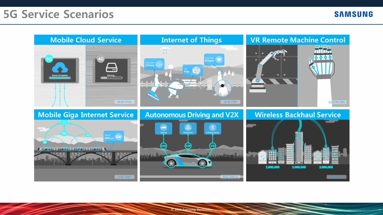
5G Use Cases & Requirements
※ ITU-R document 5D/TEMP/625
Peak 20 Gbps Edge 100 Mbps
eMBB enhanced Mobile-Broadband
10-9 Error-rate 1ms Latency
UR/LL Ultra-Reliable & Low Latency
106 Connections/km2
10 year Battery-life
mMTC massive Machine-Type Communications

© 2016 Samsung Electronics
New Spectrum Opportunities
“Below 6 GHz” and “Above 6 GHz” Spectrum Bands Considered for 5G Much larger bandwidths available in spectrum bands above 6 GHz FCC NPRM : 28 / 37 / 39 / 64-71 GHz considered for mobile radio services
Below 6 GHz Above 6 GHz
APT
CEPT
CITEL
RCC
ASMG
1427 -1452
1492 -1518
1427 -1518
1427 -1518
1452 -1518
3400 -3800
3400 -3600
5925 -6425
3400 -3600
10 -10.45
23.15 -23.6
24.25 -27.5
27.5 -29.5
31.8 -33
37 40.5
45.5 -47
47.2 -50.2
50.4 -52.6
59.3 -76
24.5 -27.5
25.25 -25.5
31.8 -33.4
31.8 -33.4
39 -47
47.2 -50.2
50.4 -52.6
66 -76
81 -86
40.5 -43.5
45.5 -48.9
66 -71
81 -86
81 -86
71 -76
25.5 -27.5
31.8 -33.4
39.5 -40.5
40.5 -41.5
45.5 -47.5
48.5 -50.2
50.4 -52.6
66 -71
71 -76
31
6-20 20-30 30-40 40-50 50-60 60-70 70-80 80-100 - 6
MHz
GHz Single band implementation for few giga-herts range exptected
© 2016 Samsung Electronics
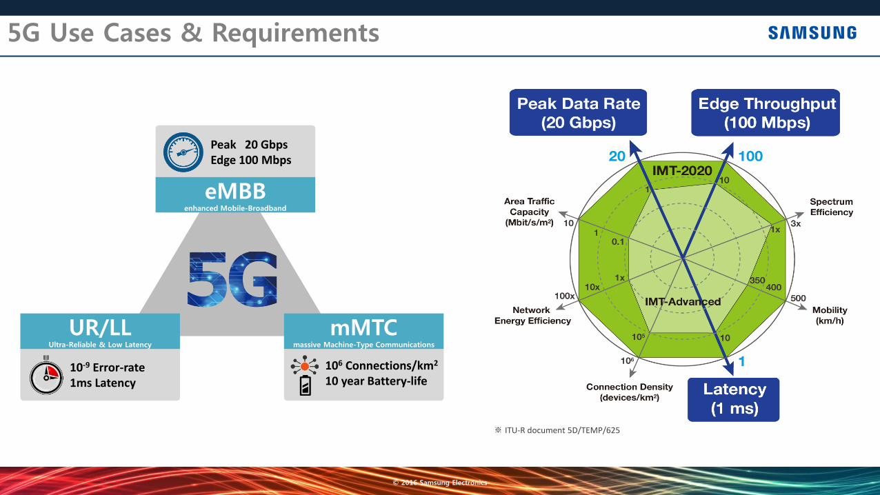
mmWave Challenges and Opportunities
Larger path-loss at high frequency bands Atmosphere loss, rain attenuation, foliage blocking Outdoor-to-indoor penetration loss Semiconductor readiness, PA efficiency, power consumption
Samsung developed the world’s first mmWave mobile prototype to verify the feasibility of mmWave mobile communications Global collaborative effort on mmWave channel modeling
Path Loss Model in Urban Environment

© 2016 Samsung Electronics
mmWave Channel Modeling
Leading Channel Modeling Activity toward Outdoor Cellular Deployment Gbps data rate support envisioned by mmWave propagation analysis
Universities & research centers NYU, USC, KAIST
Research projects 5G PPP mmMAGIC, COST IC1004
Standard Rapporteur on 3GPP 5G Channel Model SI
for > 6GHz NYU campus
Calibration
1 2 3 4 5 6 7 8 9 100
10
20
30
40
50
60
70
80
90
100
Measurement Index #
Angula
r S
pre
ad
Angle Spread Comparison @ New York
NYU Measurement
New York Ray-Tracing
50 80 100 150 200100
110
120
130
140
150
160
170
Distance between transmitter and receiver (m)
Pa
th L
oss (
dB
)
Comparison of propagation models : 28GHz
Measurment Samples - NYU Campus
Measurement-based Pathloss Model (NLoS)
Ray-tracing Samples - NYU Campus
Ray-tracing-based Pathloss Model (NLoS)
Channel modeling
Pathloss Cal.
1 10 50 100 150 25060
70
80
90
100
110
120
130
140
150
160
Distance [m]
Path
Loss [
dB
]
n,Synthesized Omni-NLoS
= 6.08dB
Synthesized Omni-NLoS
nSynthesized Omni-NLoS
= 3.58
0 50 100 150 200 250 3000
0.1
0.2
0.3
0.4
0.5
0.6
0.7
0.8
0.9
1
RMS Delay Spread [ns]
Cu
mu
lative
Dis
trib
utio
n F
un
ctio
n (
CD
F)
Delay Spread in NLoS
E[DS
Daejeon
] =55.4292 ns
E[DS
Alpensia
] =60.4132 ns
Measurement (Daejeon NLoS)
Modeling (Daejeon NLoS)
Measurement (Alpensia NLoS)
Modeling (Alpensia NLoS)
0 20 40 60 80 100 1200
0.1
0.2
0.3
0.4
0.5
0.6
0.7
0.8
0.9
1
AoA spread [deg]
Cu
mu
lative
Dis
trib
utio
n F
un
ctio
n (
CD
F)
RX Azimuth Angle Spred in NLoS
E[AoA spreadDaejeon
]=31.3912o
E[AoA spreadAlpensia
]=43.1066o
Measurement (Daejeon, NLoS)
Modeling (Daejeon, NLoS)
Measurement (Alpensia, NLoS)
Modeling (Alpensia, NLoS)
Angle Spread Cal.
Pathloss Model Delay Spread Angle Spread
TX
TX
Measurement Campaign
2018 Winter Olympic Resort
Tx
NLoS Rx
28 GHz Channel Sounder
[TX]
[RX]
© 2016 Samsung Electronics
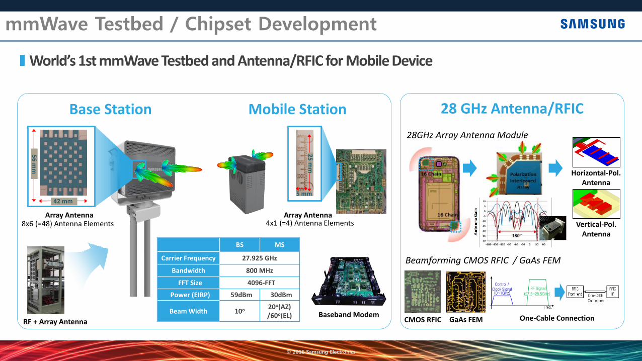
mmWave Testbed / Chipset Development
World’s 1st mmWave Testbed and Antenna/RFIC for Mobile Device
5 mm
25
mm
42 mm
56
mm
Beamforming CMOS RFIC / GaAs FEM
28GHz Array Antenna Module
© Samsung Electronics. All Rights Reserved. Confidential and Proprietary.
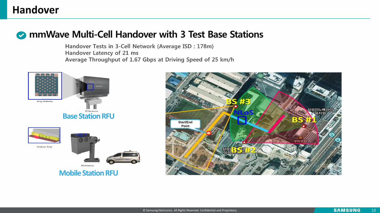
Handover
10
Start/End
Point
Base Station RFU
2.5 mm
Mobile Station RFU
mmWave Multi-Cell Handover with 3 Test Base Stations
© 2016 Samsung Electronics
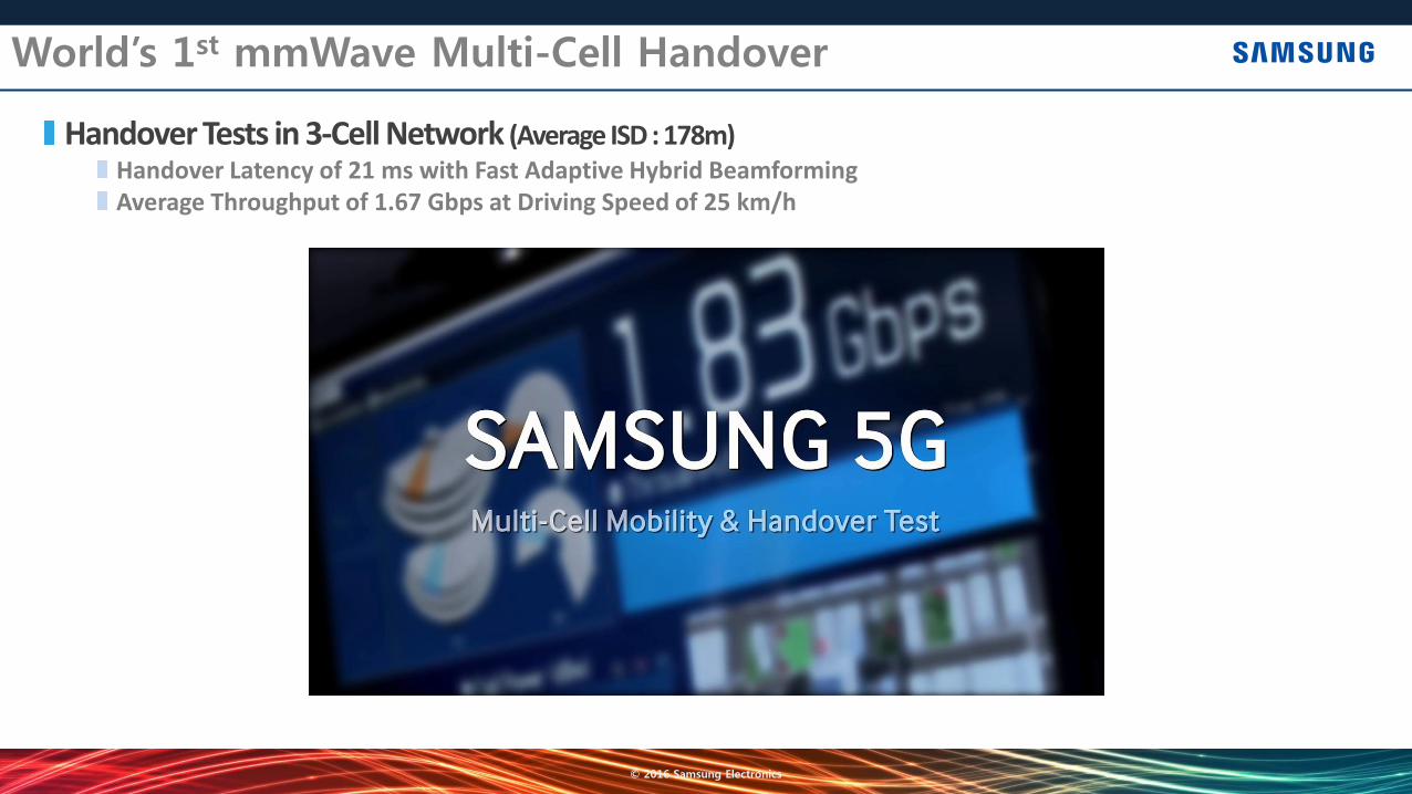
World’s 1st mmWave Multi-Cell Handover
Handover Tests in 3-Cell Network (Average ISD : 178m) Handover Latency of 21 ms with Fast Adaptive Hybrid Beamforming Average Throughput of 1.67 Gbps at Driving Speed of 25 km/h
© 2016 Samsung Electronics
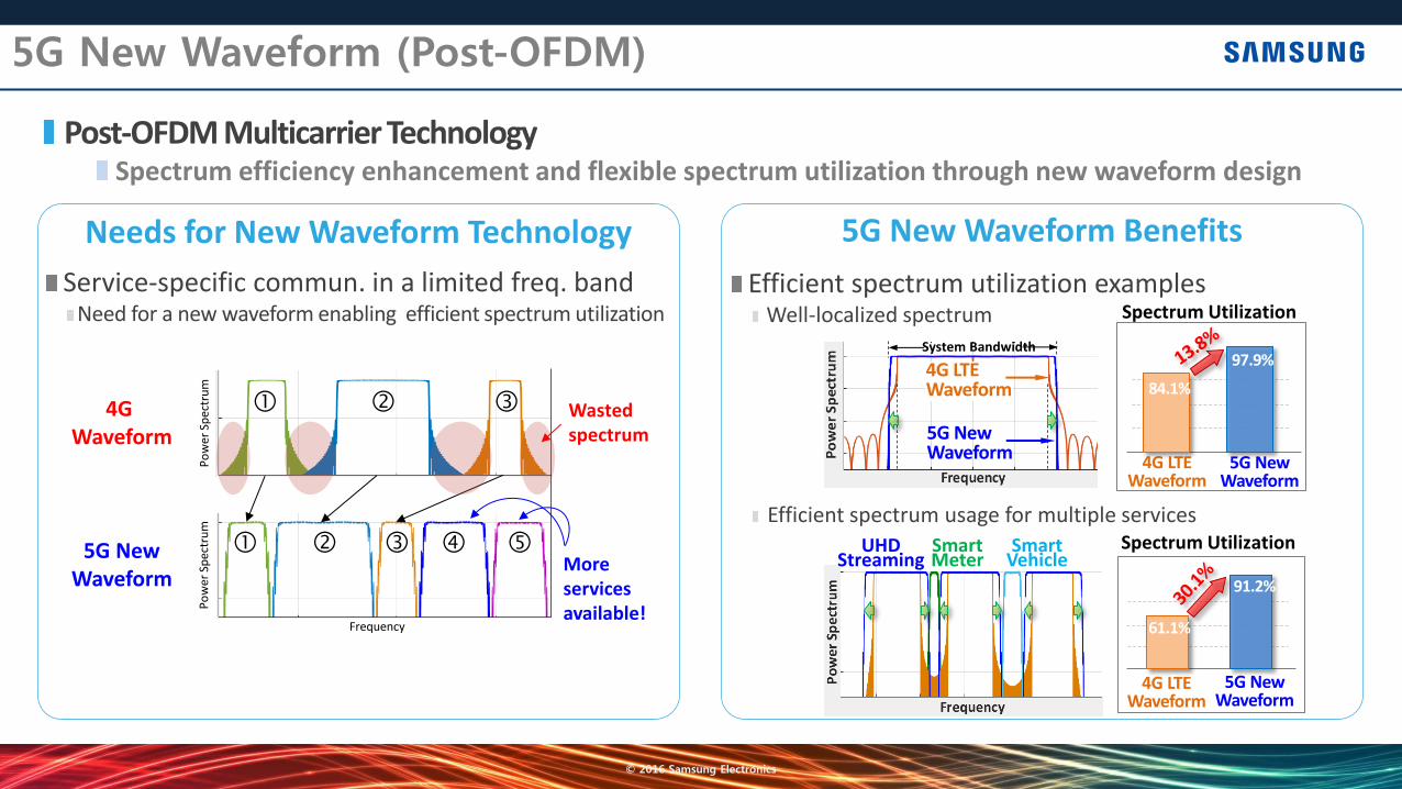
5G New Waveform (Post-OFDM)
Efficient spectrum utilization examples Well-localized spectrum
Efficient spectrum usage for multiple services
Post-OFDM Multicarrier Technology Spectrum efficiency enhancement and flexible spectrum utilization through new waveform design
4G Waveform
5G New Waveform
Po
wer
Sp
ectr
um
Frequency
Po
wer
Sp
ectr
um
More services available!
Wasted spectrum
4G LTE Waveform
5G New Waveform
84.1%
97.9%
61.1%
91.2%
5G New Waveform
4G LTE Waveform
5G New Waveform
4G LTE Waveform
System Bandwidth
Spectrum Utilization
Spectrum Utilization Smart Meter
Smart Vehicle
UHD Streaming
Service-specific commun. in a limited freq. band Need for a new waveform enabling efficient spectrum utilization
© 2016 Samsung Electronics
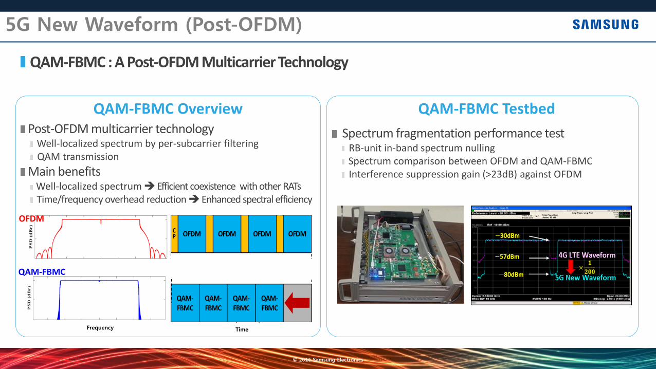
QAM-FBMC : A Post-OFDM Multicarrier Technology
(In Frequency) (In Time)
OFDM
Post-OFDM multicarrier technology Well-localized spectrum by per-subcarrier filtering QAM transmission
Main benefits Well-localized spectrum Efficient coexistence with other RATs Time/frequency overhead reduction Enhanced spectral efficiency
Spectrum fragmentation performance test RB-unit in-band spectrum nulling Spectrum comparison between OFDM and QAM-FBMC Interference suppression gain (>23dB) against OFDM
5G New Waveform (Post-OFDM)
QAM-FBMC
© 2016 Samsung Electronics
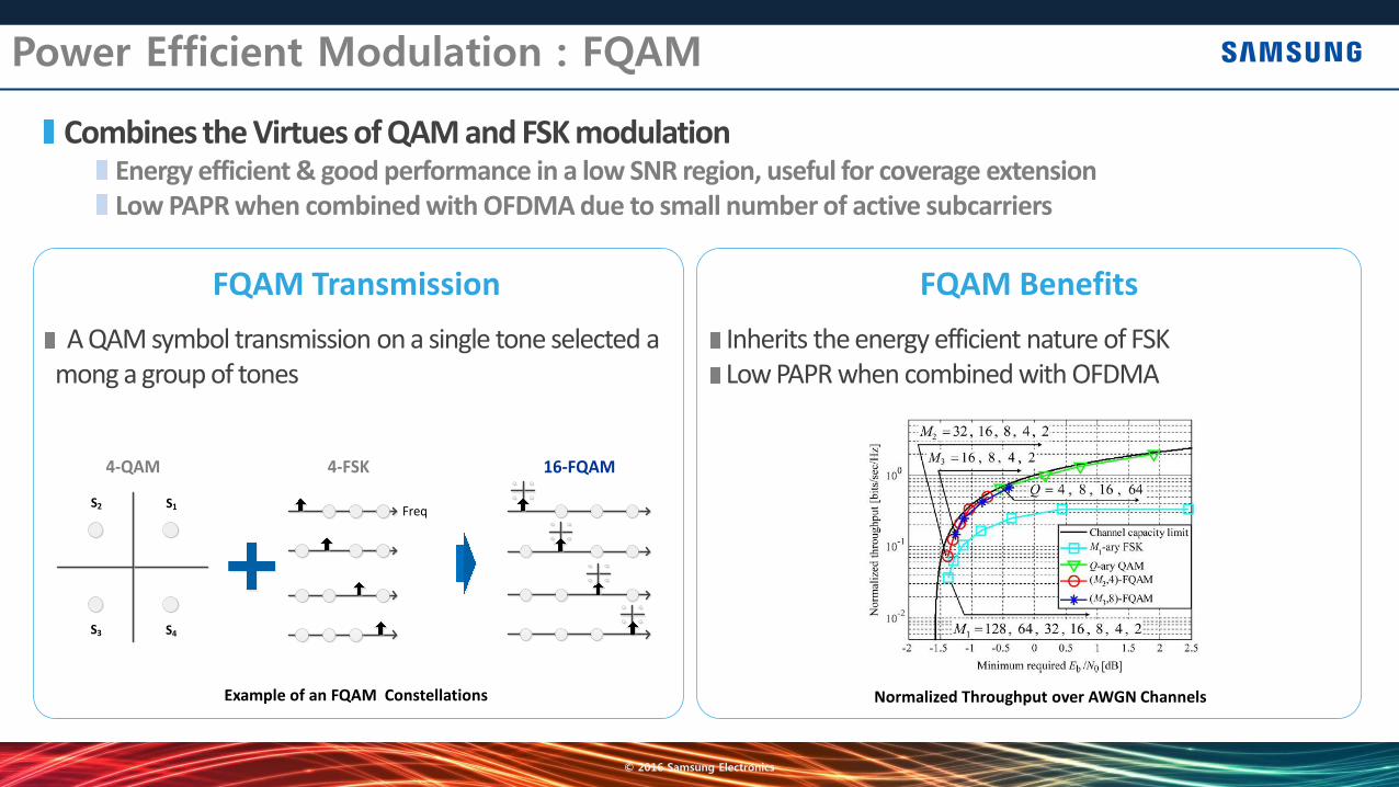
Power Efficient Modulation : FQAM
Combines the Virtues of QAM and FSK modulation Energy efficient & good performance in a low SNR region, useful for coverage extension Low PAPR when combined with OFDMA due to small number of active subcarriers
Freq
4-FSK 16-FQAM4-QAM
S1S2
S4S3
A QAM symbol transmission on a single tone selected among a group of tones
Inherits the energy efficient nature of FSK Low PAPR when combined with OFDMA

© 2016 Samsung Electronics
Low Complexity Channel Coding : LDPC
A Promising Channel Coding Scheme for Multi-Gbps Support with Low Power Consumption 5G peak data rate is 10 Gbps to 20 Gbps Low power consumption and small implementation area is essential
LDPC shows 10 times lower power w.r.t. Turbo LDPC shows 5 times smaller area for decoder implementation
[1] M. May, T. Ilnseher, N. Wehn, and W. Raab, "A 150Mbit/s 3GPP LTE tubo code decoder," in Proc. DATE, Mar. 2010. [2] S. Belfanti, etc., "A 1Gbps LTE-advanced turbo-decoder ASIC in 65nm CMOS," in Symposium on VLSI Circuits Digest of Technical Papers, 2013. [3] Y. Sun, J.R. Cavallaro, "Efficient hardware implementation of a highly-parallel 3GPP LTE/LTE-advance turbo decoder," INTEGRATION, the VLSI journal, 2011. [4] M. Weiner, B. Nikolic, and Z. Zhang, "LDPC decoder architecture for high-data rate personal-area networks," IEEE Symp. Circuits and Systems, 2011. [5] S.-Y. Hung, etc., "A 5.7Gbps row-based layered scheduling LDPC decoder for IEEE 802.15.3c applications," IEEE Asian Solid-State Circuits Conference, Nov. 2010.
Turbo
LDPC
ASIC Process
10 times
10
100
1000
10000
0.1
1
10
100
Turbo
LDPC
5 times

© 2016 Samsung Electronics
Massive MIMO Technology
FD-MIMO with Massive Antenna Technologies 2D array based adaptive beamforming at the base station
Higher-order MU-MIMO with 3D beamforming
3D-Beamforming Elevation and azimuth beamforming Full-dimension MIMO/BF support with 2D massive array
Higher-order MU-MIMO Increased order of Multi-users
supported simultaneously
Support of larger number of antenna ports MIMO/beamforming enhancements for both TDD & FDD
© 2016 Samsung Electronics
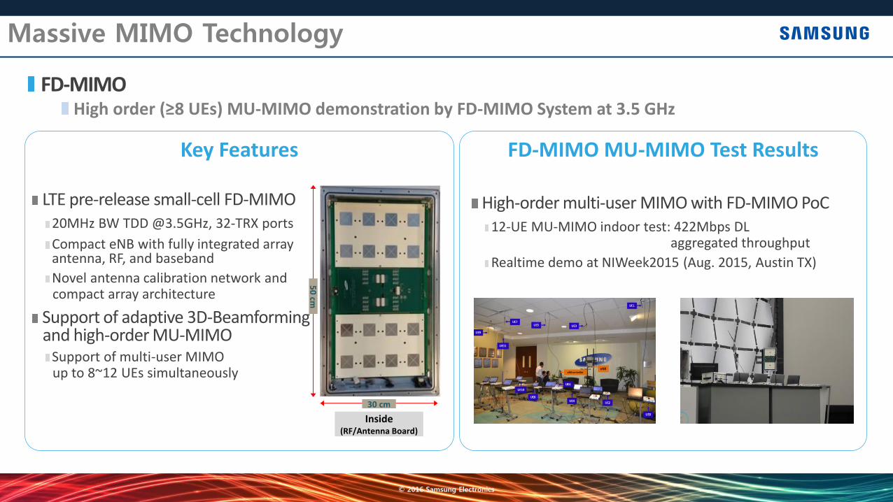
Massive MIMO Technology
FD-MIMO High order (≥8 UEs) MU-MIMO demonstration by FD-MIMO System at 3.5 GHz
LTE pre-release small-cell FD-MIMO 20MHz BW TDD @3.5GHz, 32-TRX ports
Compact eNB with fully integrated array antenna, RF, and baseband
Novel antenna calibration network and compact array architecture
Support of adaptive 3D-Beamforming and high-order MU-MIMO
Support of multi-user MIMO up to 8~12 UEs simultaneously
High-order multi-user MIMO with FD-MIMO PoC 12-UE MU-MIMO indoor test: 422Mbps DL
aggregated throughput
Realtime demo at NIWeek2015 (Aug. 2015, Austin TX)
Inside (RF/Antenna Board)
30 cm
50
cm
© 2016 Samsung Electronics
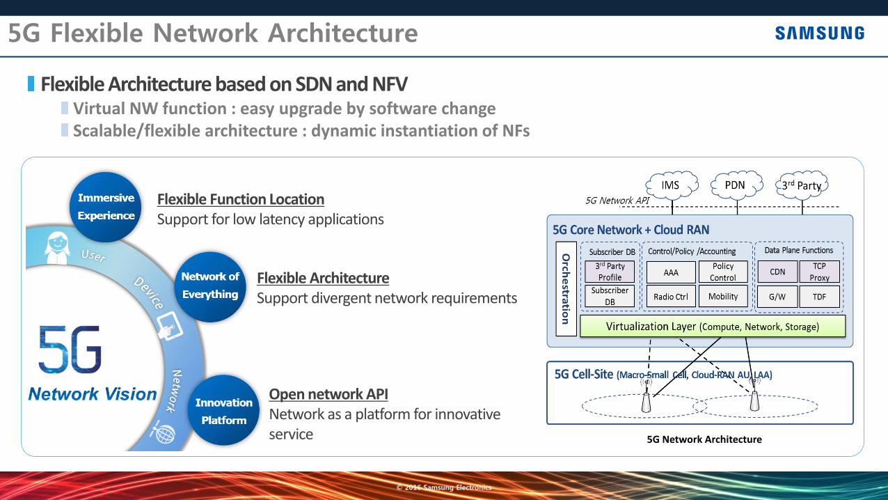
5G Flexible Network Architecture
Flexible Architecture based on SDN and NFV Virtual NW function : easy upgrade by software change Scalable/flexible architecture : dynamic instantiation of NFs
Flexible Function Location Support for low latency applications
Flexible Architecture Support divergent network requirements
Open network API Network as a platform for innovative service
© 2016 Samsung Electronics
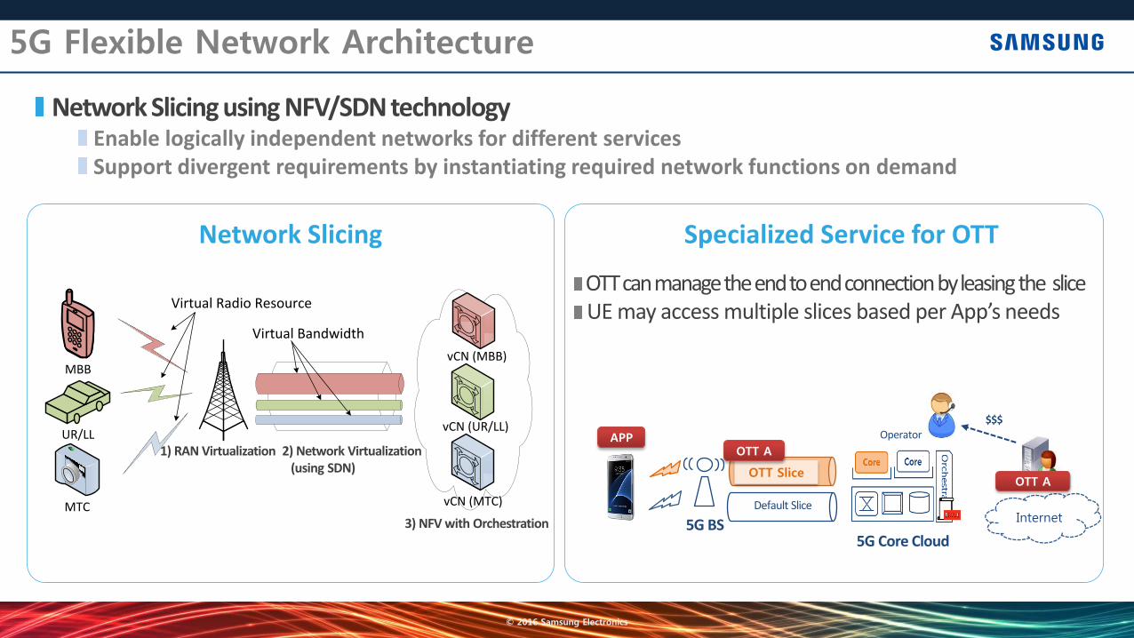
5G Flexible Network Architecture
Network Slicing using NFV/SDN technology Enable logically independent networks for different services Support divergent requirements by instantiating required network functions on demand
OTT can manage the end to end connection by leasing the slice UE may access multiple slices based per App’s needs
MTC
UR/LL
vCN (MBB)
vCN (UR/LL)
vCN (MTC)
MBB
Virtual Bandwidth
Virtual Radio Resource
1) RAN Virtualization 2) Network Virtualization (using SDN)
3) NFV with Orchestration 5G BS
Default Slice
OTT Slice
Internet
Operator
$$$
5G Core Cloud
APP OTT A
OTT A
© 2016 Samsung Electronics
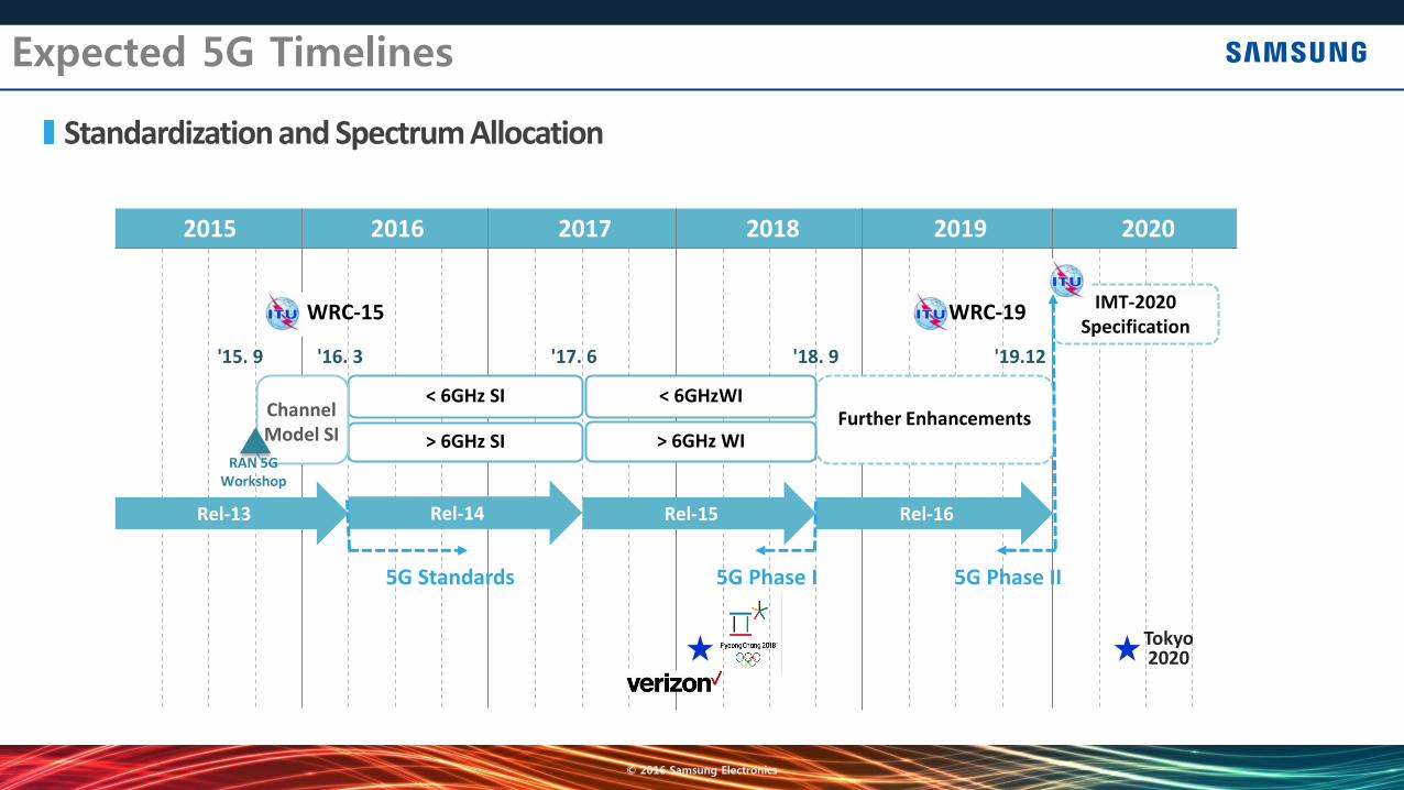
Expected 5G Timelines
Standardization and Spectrum Allocation
2015 2016 2017 2018 2019 2020
< 6GHz SI
> 6GHz SI RAN 5G
Workshop
'15. 9
Rel-15 Rel-14 Rel-13
'17. 6 '16. 3
WRC-15
Rel-16
'19.12
Further Enhancements < 6GHzWI
> 6GHz WI
'18. 9
IMT-2020 Specification
Channel Model SI
5G Standards 5G Phase I 5G Phase II
Tokyo 2020
WRC-19
© 2016 Samsung Electronics
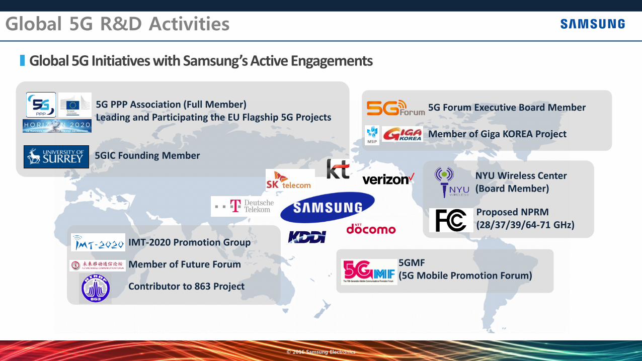
Global 5G R&D Activities
Global 5G Initiatives with Samsung’s Active Engagements
5G Forum Executive Board Member
Member of Giga KOREA Project
IMT-2020 Promotion Group
Member of Future Forum
Contributor to 863 Project
NYU Wireless Center (Board Member)
Proposed NPRM (28/37/39/64-71 GHz)
5GMF (5G Mobile Promotion Forum)
5G PPP Association (Full Member) Leading and Participating the EU Flagship 5G Projects
5GIC Founding Member

Thank you
© 2016 Samsung Electronics