Embed Size (px)
Citation preview
5854 IEEE TRANSACTIONS ON POWER ELECTRONICS, VOL. 28, NO. 12, DECEMBER 2013
Analysis and Experimental Verificationof a Fault-Tolerant HEV Powertrain
Yantao Song and Bingsen Wang, Senior Member, IEEE
Abstract—This paper presents a fault-tolerant powertrain topol-ogy for series hybrid electric vehicles (SHEVs). The introductionof a redundant phase-leg that is shared by three converters ina standard SHEV powertrain allows us to maximize the relia-bility improvement with minimal part-count increase. Therefore,the cost increase is kept to minimum as well. The new topologyfeatures fast response in fault detection and isolation, and post-fault operation at rated power throughput. Two implementationsof the fault-tolerant design are presented in conjunction with elab-orated discussion of the operating principles, control schemes, andfault diagnostic methods. The substantially improved reliabilityover standard SHEV powertrains is demonstrated by analysis ofthe Markov reliability model. Time-domain simulation based on aSaber model has been conducted and the results have verified thefeasibility and performance of the proposed SHEV drive system.A scaled-down laboratory prototype has been built and the exper-imental results further validate the robust fault detection/isolationscheme and uncompromised postfault performance.
Index Terms—Fault detection, fault tolerance, hybrid electricvehicle (HEV) powertrain, reliability.
I. INTRODUCTION
HYBRID electric vehicles (HEVs) with their competitivefuel economy have been considered as a pivotal tech-
nology to address concerns over the rapid rising of petroleumcost, increasingly worsening air pollution, and global warm-ing associated with greenhouse gas emission [1]. A literaturesurvey conducted by the authors of this paper suggests thatmajor research effort has been focused on power electronic con-verter topologies [2]–[7], design and control of traction motorsrelated to HEVs [8], energy storage unit and energy manage-ment [9]–[12], and control in the system level [13]–[15], whilesignificantly less attention has been devoted to the reliabilityand fault mitigation of HEVs’ powertrains. In fact, aggregationof many power electronic devices into drive systems of vehiclesmay adversely affect reliability of the overall system [16], [17].The reduced reliability of HEVs not only discounts fuel-savingpremium, but also increases repair time and repair cost. In lightof safety concerns, faults that occur in electric drives that are
Manuscript received September 30, 2012; revised December 8, 2012;accepted January 24, 2013. Date of current version June 6, 2013. Recommendedfor publication by Associate Editor T. Mishima.
The authors are with the Department of Electrical and Computer Engi-neering, Michigan State University, East Lansing, MI 48824 USA (e-mail:[email protected]; [email protected]).
Color versions of one or more of the figures in this paper are available onlineat http://ieeexplore.ieee.org.
Digital Object Identifier 10.1109/TPEL.2013.2245513
utilized as propulsion systems of HEVs can be critical sincean uncontrolled output torque exerts much risk on the vehi-cle’s stability, which can ultimately endanger the passengers’safety. Therefore, a fault-tolerant operation even with partialfunctionality that is commonly known as limping-home func-tion is desirable [18].
The short-switch failure and the open-switch failure are themost common types of failure modes that compromise reli-able operation of motor drive systems [19], [20]. This papercompares and contrasts several existing alternative designs withshort-switch and open-switch fault-tolerant capability employedin HEVs electrical machine driving systems in terms of perfor-mance and cost. In [21] and [22], three-leg three-phase fault-tolerant inverter for motors with accessible neutral point areinvestigated. In this type of fault-tolerant inverter, the postfaultoperation is implemented by reconfiguring the standard topol-ogy and regulating the currents in the remaining healthy legsin order to maintain the magnetomotive force (MMF) gener-ated by the stator current unchanged. The limitation of thistopology is that it requires access to the neutral point of thestator windings. A modified three-leg three-phase fault-tolerantinverter is developed for three-phase motors with three termi-nals [23]–[25]. Such three-leg fault-tolerant motor drive inverterfeatures low-part count. However, the dc-link capacitors haveto be oversized in order to absorb large current at fundamentalfrequency of the load under faulted conditions. The postfaultpower throughput is reduced to such an extent that it rendersa long-term operation unfeasible. Four-leg three-phase fault-tolerant inverter topologies do not require available midpoint ofdc-link or oversized dc-link capacitors [18], [23], [26]–[29]. Aslight modification enables these four-leg inverter topologies tobe applied to both three-terminal and four-terminal three-phasemotors. Without oversizing the inverter, some of the four-leginverters can provide the same postfault power throughput asthe one under the healthy operating condition. The main draw-back lies in the high component count of auxiliary devices andthe associated higher cost. The multiphase motor drive inverterhas inherent redundancy that can be utilized. But such a con-figuration is only suitable for motors with a particular designstructure, which will exclude its applicability to general mo-tor drive systems [30]. The authors of [31], present a cascadedinverter topology that has an inherent fault-tolerant capabilitydue to the redundancy of the switching states. However, sim-ilar to multiphase inverter, this fault-tolerant topology is alsoonly suitable for motors with special structure. Some modi-fied matrix converter and multilevel converters feature superiorfault-tolerant capability [32]–[34]. However, these high-powerconverters are not suitable for application of HEVs.
0885-8993/$31.00 © 2013 IEEE
SONG AND WANG: ANALYSIS AND EXPERIMENTAL VERIFICATION OF A FAULT-TOLERANT HEV POWERTRAIN 5855
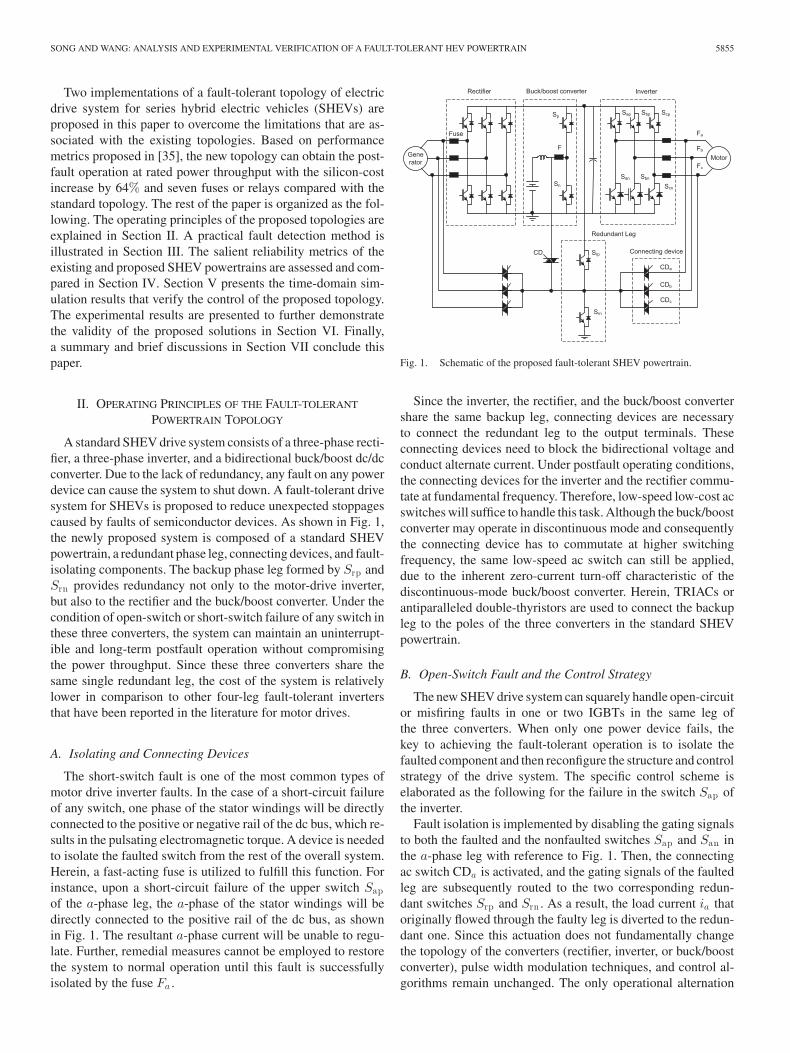
Two implementations of a fault-tolerant topology of electricdrive system for series hybrid electric vehicles (SHEVs) areproposed in this paper to overcome the limitations that are as-sociated with the existing topologies. Based on performancemetrics proposed in [35], the new topology can obtain the post-fault operation at rated power throughput with the silicon-costincrease by 64% and seven fuses or relays compared with thestandard topology. The rest of the paper is organized as the fol-lowing. The operating principles of the proposed topologies areexplained in Section II. A practical fault detection method isillustrated in Section III. The salient reliability metrics of theexisting and proposed SHEV powertrains are assessed and com-pared in Section IV. Section V presents the time-domain sim-ulation results that verify the control of the proposed topology.The experimental results are presented to further demonstratethe validity of the proposed solutions in Section VI. Finally,a summary and brief discussions in Section VII conclude thispaper.
II. OPERATING PRINCIPLES OF THE FAULT-TOLERANT
POWERTRAIN TOPOLOGY
A standard SHEV drive system consists of a three-phase recti-fier, a three-phase inverter, and a bidirectional buck/boost dc/dcconverter. Due to the lack of redundancy, any fault on any powerdevice can cause the system to shut down. A fault-tolerant drivesystem for SHEVs is proposed to reduce unexpected stoppagescaused by faults of semiconductor devices. As shown in Fig. 1,the newly proposed system is composed of a standard SHEVpowertrain, a redundant phase leg, connecting devices, and fault-isolating components. The backup phase leg formed by Srp andSrn provides redundancy not only to the motor-drive inverter,but also to the rectifier and the buck/boost converter. Under thecondition of open-switch or short-switch failure of any switch inthese three converters, the system can maintain an uninterrupt-ible and long-term postfault operation without compromisingthe power throughput. Since these three converters share thesame single redundant leg, the cost of the system is relativelylower in comparison to other four-leg fault-tolerant invertersthat have been reported in the literature for motor drives.
A. Isolating and Connecting Devices
The short-switch fault is one of the most common types ofmotor drive inverter faults. In the case of a short-circuit failureof any switch, one phase of the stator windings will be directlyconnected to the positive or negative rail of the dc bus, which re-sults in the pulsating electromagnetic torque. A device is neededto isolate the faulted switch from the rest of the overall system.Herein, a fast-acting fuse is utilized to fulfill this function. Forinstance, upon a short-circuit failure of the upper switch Sapof the a-phase leg, the a-phase of the stator windings will bedirectly connected to the positive rail of the dc bus, as shownin Fig. 1. The resultant a-phase current will be unable to regu-late. Further, remedial measures cannot be employed to restorethe system to normal operation until this fault is successfullyisolated by the fuse Fa .
Fig. 1. Schematic of the proposed fault-tolerant SHEV powertrain.
Since the inverter, the rectifier, and the buck/boost convertershare the same backup leg, connecting devices are necessaryto connect the redundant leg to the output terminals. Theseconnecting devices need to block the bidirectional voltage andconduct alternate current. Under postfault operating conditions,the connecting devices for the inverter and the rectifier commu-tate at fundamental frequency. Therefore, low-speed low-cost acswitches will suffice to handle this task. Although the buck/boostconverter may operate in discontinuous mode and consequentlythe connecting device has to commutate at higher switchingfrequency, the same low-speed ac switch can still be applied,due to the inherent zero-current turn-off characteristic of thediscontinuous-mode buck/boost converter. Herein, TRIACs orantiparalleled double-thyristors are used to connect the backupleg to the poles of the three converters in the standard SHEVpowertrain.
B. Open-Switch Fault and the Control Strategy
The new SHEV drive system can squarely handle open-circuitor misfiring faults in one or two IGBTs in the same leg ofthe three converters. When only one power device fails, thekey to achieving the fault-tolerant operation is to isolate thefaulted component and then reconfigure the structure and controlstrategy of the drive system. The specific control scheme iselaborated as the following for the failure in the switch Sap ofthe inverter.
Fault isolation is implemented by disabling the gating signalsto both the faulted and the nonfaulted switches Sap and San inthe a-phase leg with reference to Fig. 1. Then, the connectingac switch CDa is activated, and the gating signals of the faultedleg are subsequently routed to the two corresponding redun-dant switches Srp and Srn . As a result, the load current ia thatoriginally flowed through the faulty leg is diverted to the redun-dant one. Since this actuation does not fundamentally changethe topology of the converters (rectifier, inverter, or buck/boostconverter), pulse width modulation techniques, and control al-gorithms remain unchanged. The only operational alternation
5856 IEEE TRANSACTIONS ON POWER ELECTRONICS, VOL. 28, NO. 12, DECEMBER 2013
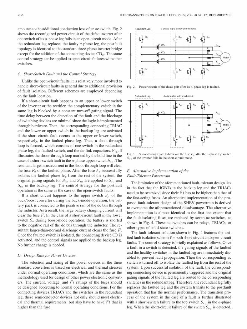
amounts to the additional conduction loss of an ac switch. Fig. 2shows the reconfigured power circuit of the dc/ac inverter afterone switch of its a-phase leg fails in an open-circuit mode. Afterthe redundant leg replaces the faulty a-phase leg, the postfaulttopology is identical to the standard three-phase inverter bridgeexcept for the addition of the connecting device CDa . The samecontrol strategy can be applied to open-circuit failures with otherswitches.
C. Short-Switch Fault and the Control Strategy
Unlike the open-circuit faults, it is relatively more involved tohandle short-circuit faults in general due to additional provisionof fault isolation. Different schemes are employed dependingon the fault location.
If a short-circuit fault happens to an upper or lower switchof the inverter or the rectifier, the complementary switch in thesame leg is blocked by a constant turn-off gating signal. Thetime delay between the detection of the fault and the blockageof switching devices are minimal since the logic is implementedthrough hardware. Then, the corresponding connecting TRIACand the lower or upper switch in the backup leg are activatedif the short-circuit fault occurs to the upper or lower switch,respectively, in the faulted phase leg. Thus, a shoot-throughloop is formed, which consists of one switch in the redundantphase leg, the faulted switch, and the dc-link capacitors. Fig. 3illustrates the shoot-through loop marked by the bold line in thecase of a short-switch fault in the a-phase upper switch Sap . Theresultant large inrush current in the shoot-through loop will clearthe fuse Fa of the faulted phase. After the fuse Fa successfullyisolates the faulted phase leg from the rest of the system, theoriginal gating signals for Sap and San are applied to Srp andSrn in the backup leg. The control strategy for the postfaultoperation is the same as the case of the open-switch faults.
If a short circuit happens to the upper switch Sp of thebuck/boost converter during the buck-mode operation, the bat-tery pack is connected to the positive rail of the dc bus throughthe inductor. As a result, the large battery charging current willclear the fuse F . In the case of a short-circuit fault in the lowerswitch Sn during boost-mode operation, the battery is shortedto the negative rail of the dc bus through the inductor. The re-sultant larger-than-normal discharge current clears the fuse F .Once the faulted switch is isolated, the connecting device CD isactivated, and the control signals are applied to the backup leg.No further change is needed.
D. Design Rule for Power Devices
The selection and sizing of the power devices in the threestandard converters is based on electrical and thermal stressesunder normal operating conditions, which are the same as themethodology used for design of other power electronic convert-ers. The current, voltage, and i2t ratings of the fuses shouldbe designed according to normal operating conditions. For theconnecting devices TRIACs and the switches in the redundantleg, these semiconductor devices not only should meet electri-cal and thermal requirements, but also have to have i2t that ishigher than the fuse.
Fig. 2. Power circuit of the dc/ac part after its a-phase leg is faulted.
Fig. 3. Shoot-through path to blow out the fuse Fa after the a-phase top switchSap of the inverter fails in the short-circuit mode.
E. Alternative Implementation of theFault-Tolerant Powertrain
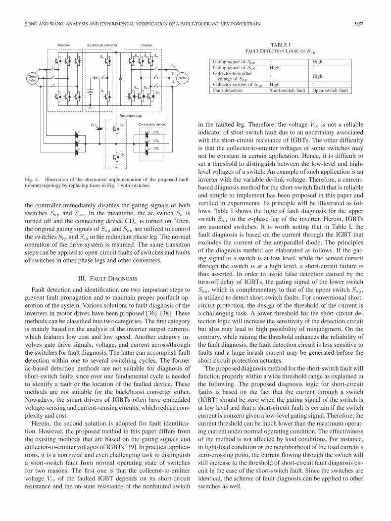
The limitation of the aforementioned fault-tolerant design liesin the fact that the IGBTs in the backup leg and the TRIACsneed to be oversized since their i2t has to be higher than that ofthe fast-acting fuses. An alternative implementation of the pro-posed fault-tolerant design of the SHEV powertrain is derivedto overcome the aforementioned disadvantage. The alternativeimplementation is almost identical to the first one except thatthe fault-isolating fuses are replaced by seven ac switches, asshown in Fig. 4. These ac switches can be relays, TRIACs, orother types of solid-state switches.
The fault-tolerant solution shown in Fig. 4 features the uni-fied fault isolation scheme for both short-circuit and open-circuitfaults. The control strategy is briefly explained as follows. Oncea fault in a switch is detected, the gating signals of the faultedand the healthy switches in the faulted leg are immediately dis-abled to prevent fault propagation. Then the corresponding acswitch is turned off to isolate the faulted leg from the rest of thesystem. Upon successful isolation of the fault, the correspond-ing connecting device is permanently triggered and the originalgating signals of the faulted leg are routed to the correspondingswitches in the redundant leg. Therefore, the redundant leg fullyreplaces the faulted leg and the system transits to the postfaultoperation that has the normal performance. The transition pro-cess of the system in the case of a fault is further illustratedwith a short-switch failure to the top switch Sap in the a-phaseleg. When the short-circuit failure of the switch Sap is detected,
SONG AND WANG: ANALYSIS AND EXPERIMENTAL VERIFICATION OF A FAULT-TOLERANT HEV POWERTRAIN 5857
Fig. 4. Illustration of the alternative implementation of the proposed fault-tolerant topology by replacing fuses in Fig. 1 with switches.
the controller immediately disables the gating signals of bothswitches Sap and San . In the meantime, the ac switch Sa isturned off and the connecting device CDa is turned on. Then,the original gating signals of Sap and San are utilized to controlthe switches Srp and Srn in the redundant phase leg. The normaloperation of the drive system is resumed. The same transitionsteps can be applied to open-circuit faults of switches and faultsof switches in other phase legs and other converters.
III. FAULT DIAGNOSIS
Fault detection and identification are two important steps toprevent fault propagation and to maintain proper postfault op-eration of the system. Various solutions to fault diagnosis of theinverters in motor drives have been proposed [36]–[38]. Thesemethods can be classified into two categories. The first categoryis mainly based on the analysis of the inverter output currents,which features low cost and low speed. Another category in-volves gate drive signals, voltage, and current across/throughthe switches for fault diagnosis. The latter can accomplish faultdetection within one to several switching cycles. The formerac-based detection methods are not suitable for diagnosis ofshort-switch faults since over one fundamental cycle is neededto identify a fault or the location of the faulted device. Thesemethods are not suitable for the buck/boost converter either.Nowadays, the smart drivers of IGBTs often have embeddedvoltage-sensing and current-sensing circuits, which reduce com-plexity and cost.
Herein, the second solution is adopted for fault identifica-tion. However, the proposed method in this paper differs fromthe existing methods that are based on the gating signals andcollector-to-emitter voltages of IGBTs [39]. In practical applica-tions, it is a nontrivial and even challenging task to distinguisha short-switch fault from normal operating state of switchesfor two reasons. The first one is that the collector-to-emittervoltage Vce of the faulted IGBT depends on its short-circuitresistance and the on-state resistance of the nonfaulted switch
TABLE IFAULT DETECTION LOGIC OF Sap
in the faulted leg. Therefore, the voltage Vce is not a reliableindicator of short-switch fault due to an uncertainty associatedwith the short-circuit resistance of IGBTs. The other difficultyis that the collector-to-emitter voltages of some switches maynot be constant in certain application. Hence, it is difficult toset a threshold to distinguish between the low-level and high-level voltages of a switch. An example of such application is aninverter with the variable dc-link voltage. Therefore, a current-based diagnosis method for the short-switch fault that is reliableand simple to implement has been proposed in this paper andverified in experiments. Its principle will be illustrated as fol-lows. Table I shows the logic of fault diagnosis for the upperswitch Sap in the a-phase leg of the inverter. Herein, IGBTsare assumed switches. It is worth noting that in Table I, thefault diagnosis is based on the current through the IGBT thatexcludes the current of the antiparallel diode. The principlesof the diagnosis method are elaborated as follows. If the gat-ing signal to a switch is at low level, while the sensed currentthrough the switch is at a high level, a short-circuit failure isthus asserted. In order to avoid false detection caused by theturn-off delay of IGBTs, the gating signal of the lower switchSan , which is complementary to that of the upper switch Sap ,is utilized to detect short-switch faults. For conventional short-circuit protection, the design of the threshold of the current isa challenging task. A lower threshold for the short-circuit de-tection logic will increase the sensitivity of the detection circuitbut also may lead to high possibility of misjudgment. On thecontrary, while raising the threshold enhances the reliability ofthe fault diagnosis, the fault detection circuit is less sensitive tofaults and a large inrush current may be generated before theshort-circuit protection actuates.
The proposed diagnosis method for the short-switch fault willfunction properly within a wide threshold range as explained inthe following. The proposed diagnosis logic for short-circuitfaults is based on the fact that the current through a switch(IGBT) should be zero when the gating signal of the switch isat low level and that a short-circuit fault is certain if the switchcurrent is nonzero given a low-level gating signal. Therefore, thecurrent threshold can be much lower than the maximum operat-ing current under normal operating condition. The effectivenessof the method is not affected by load conditions. For instance,in light-load condition or the neighborhood of the load current’szero-crossing point, the current flowing through the switch willstill increase to the threshold of short-circuit fault diagnosis cir-cuit in the case of the short-switch fault. Since the switches areidentical, the scheme of fault diagnosis can be applied to otherswitches as well.

5858 IEEE TRANSACTIONS ON POWER ELECTRONICS, VOL. 28, NO. 12, DECEMBER 2013
The diagnosis logic for open-switch fault is based on thegating signal and the collector-to-emitter voltage Vce of a switch(IGBT). The open-circuit fault that occurs to the upper switchSap of the a-phase leg is taken as an illustrative case. Under thenormal operating condition, when the gating signal to switchSap is high, the voltage Vce across the switch Sap must be atlow level. Otherwise, if the voltage Vce of the switch Sap is athigh level when its gating signal is at high level, a open-circuitfault is certain to occurs to Sap . An open-switch fault is asserted.
IV. RELIABILITY ANALYSIS OF THE FAULT-TOLERANT
SHEV POWERTRAIN
The reliability of the system is closely related to the repaircost and repair time since higher reliability of the system willamount to less maintenance. This section quantitatively assessesthe reliability of the proposed and the standard SHEV drive sys-tems. In the assessment of the new drive system’s reliabilityimprovement, only semiconductor devices IGBTs and TRIACsare considered to demonstrate the methodology although inclu-sion of other passive components is rather straightforward.
A. Components Failure Rates
The reliability handbook MIL-217F [40] provides an exten-sive database of various types of parts. Therefore, it is widelyaccepted and frequently utilized to determine reliability of var-ious electronic equipment. In order to make use of the failurerate models of components from the handbook, the followingoperating conditions have been assumed:
1) the power ratings are 100 kW for the inverter, 70 kW forthe rectifier, and 30 kW for the buck/boost converter;
2) the dc-link voltage is 250–600 V, and, therefore, deviceswith the rating of 1200 V/600 A are selected;
3) the junction temperature of devices is 150 ◦C;4) reliability of IGBTs and TRIACs are considered;5) failure rates of components in inactive mode equal zero.The reliability model of TRIAC is determined by
λSCR = λbπT πRπS πQπE (1)
whereλb base failure rate;πT temperature factor;πR current rating factor;πS : voltage stress factor;πQ : quality factor;πE environmental factor.
The MIL-HDBK-217F contains no reliability data about IG-BTs. In consideration of the similarity between the internalstructures of IGBTs and MOSFETs, the failure rate model ofMOSFTs is chosen to estimate failure rates of IGBTs. Hence,the failure rate of IGBTs can be expressed as
λIGBT = λbπT πAπE πQ (2)
where πA is application factor while the other parameters havebeen explained in (1).
TABLE IIFAILURE RATES OF COMPONENTS
Fig. 5. State transition diagram.
Based on the assumed operating conditions, known as envi-ronmental and application conditions, the failure rates of IGBTand TRIAC are evaluated and listed in Table II.
B. Fundamentals of Markov Reliability Model
At the system level, Markov chain is an effective approach toevaluating the reliability of fault-tolerant systems. This approachcan cover many features of redundant systems such as sequenceof failures, failure coverage, and state-dependent failure rates.Markov model can be utilized to estimate various reliabilitymetrics such as failure rate, mean time to failure (MTTF), reli-ability, and availability among others. Firstly a stochastic statevariable X(t), t > 0 is defined, which represents states of thesystem. At time instant t, the probability Pi(t) for the system tobe in the ith state is expressed as
Pi(t) = P{X(t) = i}. (3)
If the system is in the ith state at time t, the probability Pij (t)that the system transitions to the jth state after a time intervalΔt is
Pij (t) = P{X(t + Δt) = j|X(t) = i}. (4)
The transition rate αij that denotes the probability of sys-tem transitioning from state i to state j during the time unit isdetermined by
αij = limΔt→0
Pij (t)Δt
. (5)
Transition rates of the fault-tolerant system are analogous tothe failure rates and repair rates of non-redundant systems. Thetransition amongst different states of a system is caused byfailure and repair events of components. Fig. 5 illustrates thestate transition diagram for the simple case of two states. If asystem has k states, then the state equation is expressed as [41]
d
dt
⎡⎢⎢⎣
P0(t)P1(t)
...Pk (t)
⎤⎥⎥⎦ =
⎡⎢⎢⎣
−α00 α01 · · · α0k
α10 −α11 · · · α1k...
... · · ·...
αk0 αk1 · · · −αkk
⎤⎥⎥⎦
⎡⎢⎢⎣
P0(t)P1(t)
...Pk (t)
⎤⎥⎥⎦.
(6)The probabilities that the system is in each state attime t can be obtained by solving the state equation(6). Probabilities P0(t), P1(t), . . . , Pm (t), correspond to nor-mal or degraded states 0, 1, . . . ,m, while probabilities
SONG AND WANG: ANALYSIS AND EXPERIMENTAL VERIFICATION OF A FAULT-TOLERANT HEV POWERTRAIN 5859
Pm+1(t), Pm+2(t), . . . , Pk (t) correspond to failed states m +1,m + 2, . . . , k. The reliability function of the system is the sumof probabilities functions of all functional (non-failed) states,which is mathematically expressed as
R(t) =m∑
i=0
Pi(t). (7)
C. Reliability Evaluation of the SHEV Driving System
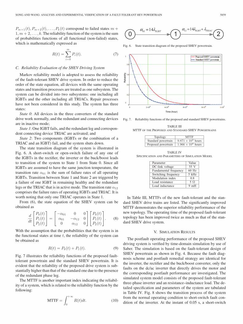
Markov reliability model is adopted to assess the reliabilityof the fault-tolerant SHEV drive system. In order to reduce theorder of the state equation, all devices with the same operatingstates and transition processes are treated as one subsystem. Thesystem can be divided into two subsystems: one including allIGBTs and the other including all TRIACs. Repair processeshave not been considered in this study. The system has threestates:
State 0: All devices in the three converters of the standarddrive work normally, and the redundant and connecting devicesare in inactive mode;
State 1: One IGBT fails, and the redundant leg and correspon-dent connecting device TRIAC are activated; and
State 2: Two components (IGBTs or the combination of aTRIAC and an IGBT) fail, and the system shuts down.
The state transition diagram of the system is illustrated inFig. 6. A short-switch or open-switch failure of any one ofthe IGBTs in the rectifier, the inverter or the buck/boost leadsto transition of the system to State 1 from State 0. Since allIGBTs are assumed to have the same junction temperature, thetransition rate α01 is the sum of failure rates of all operatingIGBTs. Transition between State 1 and State 2 are triggered bya failure of one IGBT in remaining healthy and the redundantlegs or the TRIAC that is in active mode. The transition rate α12comprises the failure rates of operating IGBTs and TRIAC. It isworth noting that only one TRIAC operates in State 1.
From (6), the state equation of the SHEV system can beobtained as
d
dt
⎡⎣
P0(t)P1(t)P2(t)
⎤⎦ =
⎡⎣−α01 0 0α01 −α12 00 α12 0
⎤⎦
⎡⎣
P0(t)P1(t)P2(t)
⎤⎦. (8)
With the assumption that the probabilities that the system is inthe functional states at time t, the reliability of the system canbe obtained as
R(t) = P0(t) + P1(t). (9)
Fig. 7 illustrates the reliability functions of the proposed fault-tolerant powertrain and the standard SHEV powertrain. It isevident that the reliability of the proposed drive system is sub-stantially higher than that of the standard one due to the presenceof the redundant phase leg.
The MTTF is another important index indicating the reliabil-ity of a system, which is related to the reliability function by thefollowing:
MTTF =∫ +∞
0R(t)dt. (10)
Fig. 6. State transition diagram of the proposed SHEV powertrain.
Fig. 7. Reliability functions of the proposed and standard SHEV powertrains.
TABLE IIIMTTF OF THE PROPOSED AND STANDARD SHEV POWERTRAINS
TABLE IVSPECIFICATION AND PARAMETERS OF SIMULATION MODEL
In Table III, MTTFs of the new fault-tolerant and the stan-dard SHEV drive trains are listed. The significantly improvedMTTF demonstrates the superior reliability performance of thenew topology. The operating time of the proposed fault-toleranttopology has been improved twice as much as that of the stan-dard SHEV drive system.
V. SIMULATION RESULTS
The postfault operating performance of the proposed SHEVdriving system is verified by time-domain simulation by use ofSaber. The simulation is based on the fault-tolerant design ofSHEV powertrain as shown in Fig. 4. Because the fault diag-nosis scheme and postfault remedial strategy are identical forthe inverter, the rectifier and the buck/boost converter, only thefaults on the dc/ac inverter that directly drives the motor andthe corresponding postfault performance are investigated. Thesimulated system model consists of the proposed fault-tolerantthree-phase inverter and an resistance–inductance load. The de-tailed specification and parameters of the system are tabulatedin Table IV. Fig. 8 shows the transition process of the systemfrom the normal operating condition to short-switch fault con-dition of the inverter. At the instant of 0.05 s, a short-switch
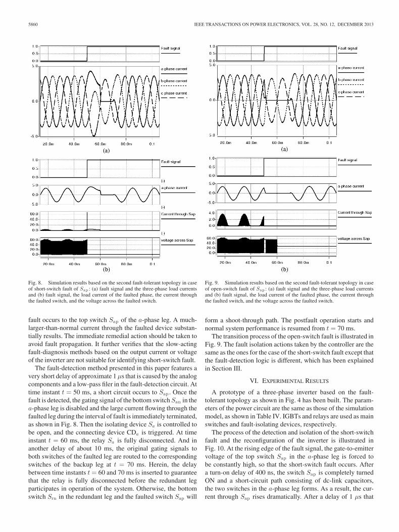
5860 IEEE TRANSACTIONS ON POWER ELECTRONICS, VOL. 28, NO. 12, DECEMBER 2013
Fig. 8. Simulation results based on the second fault-tolerant topology in caseof short-switch fault of Sap : (a) fault signal and the three-phase load currentsand (b) fault signal, the load current of the faulted phase, the current throughthe faulted switch, and the voltage across the faulted switch.
fault occurs to the top switch Sap of the a-phase leg. A much-larger-than-normal current through the faulted device substan-tially results. The immediate remedial action should be taken toavoid fault propagation. It further verifies that the slow-actingfault-diagnosis methods based on the output current or voltageof the inverter are not suitable for identifying short-switch fault.
The fault-detection method presented in this paper features avery short delay of approximate 1 μs that is caused by the analogcomponents and a low-pass filer in the fault-detection circuit. Attime instant t = 50 ms, a short circuit occurs to Sap . Once thefault is detected, the gating signal of the bottom switch San in thea-phase leg is disabled and the large current flowing through thefaulted leg during the interval of fault is immediately terminated,as shown in Fig. 8. Then the isolating device Sa is controlled tobe open, and the connecting device CDa is triggered. At timeinstant t = 60 ms, the relay Sa is fully disconnected. And inanother delay of about 10 ms, the original gating signals toboth switches of the faulted leg are routed to the correspondingswitches of the backup leg at t = 70 ms. Herein, the delaybetween time instants t = 60 and 70 ms is inserted to guaranteethat the relay is fully disconnected before the redundant legparticipates in operation of the system. Otherwise, the bottomswitch Srn in the redundant leg and the faulted switch Sap will
Fig. 9. Simulation results based on the second fault-tolerant topology in caseof open-switch fault of Sap : (a) fault signal and the three-phase load currentsand (b) fault signal, the load current of the faulted phase, the current throughthe faulted switch, and the voltage across the faulted switch.
form a shoot-through path. The postfault operation starts andnormal system performance is resumed from t = 70 ms.
The transition process of the open-switch fault is illustrated inFig. 9. The fault isolation actions taken by the controller are thesame as the ones for the case of the short-switch fault except thatthe fault-detection logic is different, which has been explainedin Section III.
VI. EXPERIMENTAL RESULTS
A prototype of a three-phase inverter based on the fault-tolerant topology as shown in Fig. 4 has been built. The param-eters of the power circuit are the same as those of the simulationmodel, as shown in Table IV. IGBTs and relays are used as mainswitches and fault-isolating devices, respectively.
The process of the detection and isolation of the short-switchfault and the reconfiguration of the inverter is illustrated inFig. 10. At the rising edge of the fault signal, the gate-to-emittervoltage of the top switch Sap in the a-phase leg is forced tobe constantly high, so that the short-switch fault occurs. Aftera turn-on delay of 400 ns, the switch Sap is completely turnedON and a short-circuit path consisting of dc-link capacitors,the two switches in the a-phase leg forms. As a result, the cur-rent through Sap rises dramatically. After a delay of 1 μs that
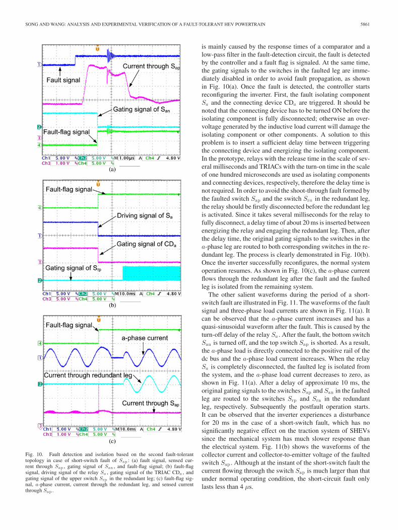
SONG AND WANG: ANALYSIS AND EXPERIMENTAL VERIFICATION OF A FAULT-TOLERANT HEV POWERTRAIN 5861
Fig. 10. Fault detection and isolation based on the second fault-toleranttopology in case of short-switch fault of Sap : (a) fault signal, sensed cur-rent through Sap , gating signal of San , and fault-flag signal; (b) fault-flagsignal, driving signal of the relay Sa , gating signal of the TRIAC CDa , andgating signal of the upper switch Srp in the redundant leg; (c) fault-flag sig-nal, a-phase current, current through the redundant leg, and sensed currentthrough Sap .
is mainly caused by the response times of a comparator and alow-pass filter in the fault-detection circuit, the fault is detectedby the controller and a fault flag is signaled. At the same time,the gating signals to the switches in the faulted leg are imme-diately disabled in order to avoid fault propagation, as shownin Fig. 10(a). Once the fault is detected, the controller startsreconfiguring the inverter. First, the fault isolating componentSa and the connecting device CDa are triggered. It should benoted that the connecting device has to be turned ON before theisolating component is fully disconnected; otherwise an over-voltage generated by the inductive load current will damage theisolating component or other components. A solution to thisproblem is to insert a sufficient delay time between triggeringthe connecting device and energizing the isolating component.In the prototype, relays with the release time in the scale of sev-eral milliseconds and TRIACs with the turn-on time in the scaleof one hundred microseconds are used as isolating componentsand connecting devices, respectively, therefore the delay time isnot required. In order to avoid the shoot-through fault formed bythe faulted switch Sap and the switch Srn in the redundant leg,the relay should be firstly disconnected before the redundant legis activated. Since it takes several milliseconds for the relay tofully disconnect, a delay time of about 20 ms is inserted betweenenergizing the relay and engaging the redundant leg. Then, afterthe delay time, the original gating signals to the switches in thea-phase leg are routed to both corresponding switches in the re-dundant leg. The process is clearly demonstrated in Fig. 10(b).Once the inverter successfully reconfigures, the normal systemoperation resumes. As shown in Fig. 10(c), the a-phase currentflows through the redundant leg after the fault and the faultedleg is isolated from the remaining system.
The other salient waveforms during the period of a short-switch fault are illustrated in Fig. 11. The waveforms of the faultsignal and three-phase load currents are shown in Fig. 11(a). Itcan be observed that the a-phase current increases and has aquasi-sinusoidal waveform after the fault. This is caused by theturn-off delay of the relay Sa . After the fault, the bottom switchSan is turned off, and the top switch Sap is shorted. As a result,the a-phase load is directly connected to the positive rail of thedc bus and the a-phase load current increases. When the relaySa is completely disconnected, the faulted leg is isolated fromthe system, and the a-phase load current decreases to zero, asshown in Fig. 11(a). After a delay of approximate 10 ms, theoriginal gating signals to the switches Sap and San in the faultedleg are routed to the switches Srp and Srn in the redundantleg, respectively. Subsequently the postfault operation starts.It can be observed that the inverter experiences a disturbancefor 20 ms in the case of a short-switch fault, which has nosignificantly negative effect on the traction system of SHEVssince the mechanical system has much slower response thanthe electrical system. Fig. 11(b) shows the waveforms of thecollector current and collector-to-emitter voltage of the faultedswitch Sap . Although at the instant of the short-switch fault thecurrent flowing through the switch Sap is much larger than thatunder normal operating condition, the short-circuit fault onlylasts less than 4 μs.
5862 IEEE TRANSACTIONS ON POWER ELECTRONICS, VOL. 28, NO. 12, DECEMBER 2013
Fig. 11. Experiment results based on the second fault-tolerant topology in caseof short-switch fault of Sap : (a) fault signal, a-phase current, b-phase current,and c-phase curren and (b) fault signal, a-phase current, sensed current throughSap , and voltage across Sap .
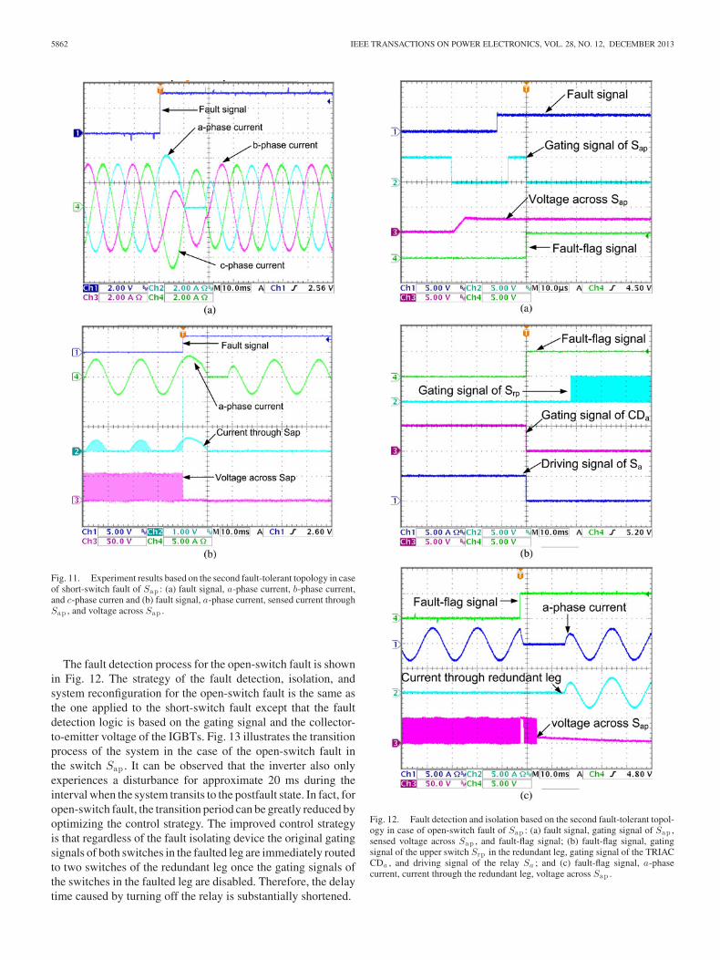
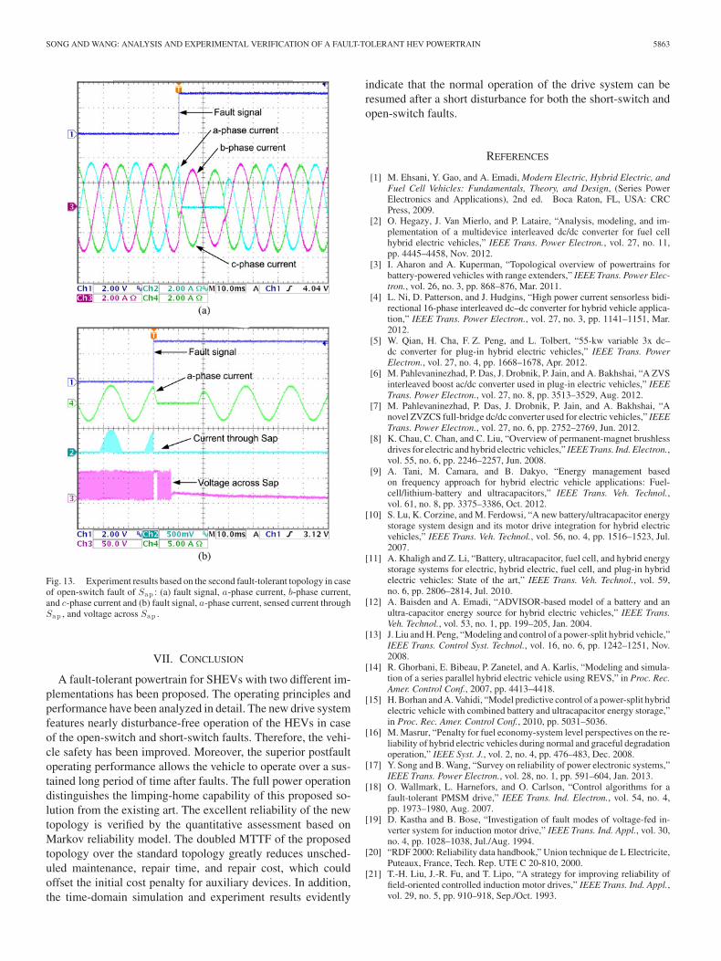
The fault detection process for the open-switch fault is shownin Fig. 12. The strategy of the fault detection, isolation, andsystem reconfiguration for the open-switch fault is the same asthe one applied to the short-switch fault except that the faultdetection logic is based on the gating signal and the collector-to-emitter voltage of the IGBTs. Fig. 13 illustrates the transitionprocess of the system in the case of the open-switch fault inthe switch Sap . It can be observed that the inverter also onlyexperiences a disturbance for approximate 20 ms during theinterval when the system transits to the postfault state. In fact, foropen-switch fault, the transition period can be greatly reduced byoptimizing the control strategy. The improved control strategyis that regardless of the fault isolating device the original gatingsignals of both switches in the faulted leg are immediately routedto two switches of the redundant leg once the gating signals ofthe switches in the faulted leg are disabled. Therefore, the delaytime caused by turning off the relay is substantially shortened.
Fig. 12. Fault detection and isolation based on the second fault-tolerant topol-ogy in case of open-switch fault of Sap : (a) fault signal, gating signal of Sap ,sensed voltage across Sap , and fault-flag signal; (b) fault-flag signal, gatingsignal of the upper switch Srp in the redundant leg, gating signal of the TRIACCDa , and driving signal of the relay Sa ; and (c) fault-flag signal, a-phasecurrent, current through the redundant leg, voltage across Sap .
SONG AND WANG: ANALYSIS AND EXPERIMENTAL VERIFICATION OF A FAULT-TOLERANT HEV POWERTRAIN 5863
Fig. 13. Experiment results based on the second fault-tolerant topology in caseof open-switch fault of Sap : (a) fault signal, a-phase current, b-phase current,and c-phase current and (b) fault signal, a-phase current, sensed current throughSap , and voltage across Sap .
VII. CONCLUSION
A fault-tolerant powertrain for SHEVs with two different im-plementations has been proposed. The operating principles andperformance have been analyzed in detail. The new drive systemfeatures nearly disturbance-free operation of the HEVs in caseof the open-switch and short-switch faults. Therefore, the vehi-cle safety has been improved. Moreover, the superior postfaultoperating performance allows the vehicle to operate over a sus-tained long period of time after faults. The full power operationdistinguishes the limping-home capability of this proposed so-lution from the existing art. The excellent reliability of the newtopology is verified by the quantitative assessment based onMarkov reliability model. The doubled MTTF of the proposedtopology over the standard topology greatly reduces unsched-uled maintenance, repair time, and repair cost, which couldoffset the initial cost penalty for auxiliary devices. In addition,the time-domain simulation and experiment results evidently
indicate that the normal operation of the drive system can beresumed after a short disturbance for both the short-switch andopen-switch faults.
REFERENCES
[1] M. Ehsani, Y. Gao, and A. Emadi, Modern Electric, Hybrid Electric, andFuel Cell Vehicles: Fundamentals, Theory, and Design, (Series PowerElectronics and Applications), 2nd ed. Boca Raton, FL, USA: CRCPress, 2009.
[2] O. Hegazy, J. Van Mierlo, and P. Lataire, “Analysis, modeling, and im-plementation of a multidevice interleaved dc/dc converter for fuel cellhybrid electric vehicles,” IEEE Trans. Power Electron., vol. 27, no. 11,pp. 4445–4458, Nov. 2012.
[3] I. Aharon and A. Kuperman, “Topological overview of powertrains forbattery-powered vehicles with range extenders,” IEEE Trans. Power Elec-tron., vol. 26, no. 3, pp. 868–876, Mar. 2011.
[4] L. Ni, D. Patterson, and J. Hudgins, “High power current sensorless bidi-rectional 16-phase interleaved dc–dc converter for hybrid vehicle applica-tion,” IEEE Trans. Power Electron., vol. 27, no. 3, pp. 1141–1151, Mar.2012.
[5] W. Qian, H. Cha, F. Z. Peng, and L. Tolbert, “55-kw variable 3x dc–dc converter for plug-in hybrid electric vehicles,” IEEE Trans. PowerElectron., vol. 27, no. 4, pp. 1668–1678, Apr. 2012.
[6] M. Pahlevaninezhad, P. Das, J. Drobnik, P. Jain, and A. Bakhshai, “A ZVSinterleaved boost ac/dc converter used in plug-in electric vehicles,” IEEETrans. Power Electron., vol. 27, no. 8, pp. 3513–3529, Aug. 2012.
[7] M. Pahlevaninezhad, P. Das, J. Drobnik, P. Jain, and A. Bakhshai, “Anovel ZVZCS full-bridge dc/dc converter used for electric vehicles,” IEEETrans. Power Electron., vol. 27, no. 6, pp. 2752–2769, Jun. 2012.
[8] K. Chau, C. Chan, and C. Liu, “Overview of permanent-magnet brushlessdrives for electric and hybrid electric vehicles,” IEEE Trans. Ind. Electron.,vol. 55, no. 6, pp. 2246–2257, Jun. 2008.
[9] A. Tani, M. Camara, and B. Dakyo, “Energy management basedon frequency approach for hybrid electric vehicle applications: Fuel-cell/lithium-battery and ultracapacitors,” IEEE Trans. Veh. Technol.,vol. 61, no. 8, pp. 3375–3386, Oct. 2012.
[10] S. Lu, K. Corzine, and M. Ferdowsi, “A new battery/ultracapacitor energystorage system design and its motor drive integration for hybrid electricvehicles,” IEEE Trans. Veh. Technol., vol. 56, no. 4, pp. 1516–1523, Jul.2007.
[11] A. Khaligh and Z. Li, “Battery, ultracapacitor, fuel cell, and hybrid energystorage systems for electric, hybrid electric, fuel cell, and plug-in hybridelectric vehicles: State of the art,” IEEE Trans. Veh. Technol., vol. 59,no. 6, pp. 2806–2814, Jul. 2010.
[12] A. Baisden and A. Emadi, “ADVISOR-based model of a battery and anultra-capacitor energy source for hybrid electric vehicles,” IEEE Trans.Veh. Technol., vol. 53, no. 1, pp. 199–205, Jan. 2004.
[13] J. Liu and H. Peng, “Modeling and control of a power-split hybrid vehicle,”IEEE Trans. Control Syst. Technol., vol. 16, no. 6, pp. 1242–1251, Nov.2008.
[14] R. Ghorbani, E. Bibeau, P. Zanetel, and A. Karlis, “Modeling and simula-tion of a series parallel hybrid electric vehicle using REVS,” in Proc. Rec.Amer. Control Conf., 2007, pp. 4413–4418.
[15] H. Borhan and A. Vahidi, “Model predictive control of a power-split hybridelectric vehicle with combined battery and ultracapacitor energy storage,”in Proc. Rec. Amer. Control Conf., 2010, pp. 5031–5036.
[16] M. Masrur, “Penalty for fuel economy-system level perspectives on the re-liability of hybrid electric vehicles during normal and graceful degradationoperation,” IEEE Syst. J., vol. 2, no. 4, pp. 476–483, Dec. 2008.
[17] Y. Song and B. Wang, “Survey on reliability of power electronic systems,”IEEE Trans. Power Electron., vol. 28, no. 1, pp. 591–604, Jan. 2013.
[18] O. Wallmark, L. Harnefors, and O. Carlson, “Control algorithms for afault-tolerant PMSM drive,” IEEE Trans. Ind. Electron., vol. 54, no. 4,pp. 1973–1980, Aug. 2007.
[19] D. Kastha and B. Bose, “Investigation of fault modes of voltage-fed in-verter system for induction motor drive,” IEEE Trans. Ind. Appl., vol. 30,no. 4, pp. 1028–1038, Jul./Aug. 1994.
[20] “RDF 2000: Reliability data handbook,” Union technique de L Electricite,Puteaux, France, Tech. Rep. UTE C 20-810, 2000.
[21] T.-H. Liu, J.-R. Fu, and T. Lipo, “A strategy for improving reliability offield-oriented controlled induction motor drives,” IEEE Trans. Ind. Appl.,vol. 29, no. 5, pp. 910–918, Sep./Oct. 1993.

5864 IEEE TRANSACTIONS ON POWER ELECTRONICS, VOL. 28, NO. 12, DECEMBER 2013
[22] J.-R. Fu and T. Lipo, “A strategy to isolate the switching device fault of acurrent regulated motor drive,” in Proc. Rec. IEEE Ind. Appl. Soc. Annu.Meet., Oct. 1993, vol. 2, pp. 1015–1020.
[23] R. de Araujo Ribeiro, C. Jacobina, E. da Silva, and A. Lima, “Fault-tolerant voltage-fed PWM inverter AC motor drive systems,” IEEE Trans.Ind. Electron., vol. 51, no. 2, pp. 439–446, Apr. 2004.
[24] A. Mendes, X. Lopez-Fernandez, and A. Marques Cardoso, “Thermal per-formance of a three-phase induction motor under fault tolerant operatingstrategies,” IEEE Trans. Power Electron., vol. 23, no. 3, pp. 1537–1544,May 2008.
[25] H. Lin, H. Li, Y. Wang, M. Li, P. Wen, and C. Zhang, “On inverter fault-tolerant operation vector control of a PMSM drive,” in Proc. Rec. Intell.Comput. Intell. Syst., 2009, pp. 522–526.
[26] S. Bolognani, M. Zordan, and M. Zigliotto, “Experimental fault-tolerantcontrol of a PMSM drive,” IEEE Trans. Ind. Electron., vol. 47, no. 5,pp. 1134–1141, Oct. 2000.
[27] J. Guitard, F. Richard, and K. Bouallaga, “Fault-tolerant inverter withreal-time monitoring for aerospace applications,” in Proc. Rec. PowerElectron. Motion Contr. Conf., 2010, pp. T9-1–T9-6.
[28] K. D. Hoang, Z. Q. Zhu, M. P. Foster, and D. A. Stone, “Comparativestudy of current vector control performance of alternate fault tolerantinverter topologies for three-phase PM brushless AC machine with onephase open-circuit fault,” in Proc. Rec. Power Electron. Mach. Drives,2010, pp. 1–6.
[29] R. Errabelli and P. Mutschler, “Fault-tolerant voltage source inverter forpermanent magnet drives,” IEEE Trans. Power Electron., vol. 27, no. 2,pp. 500–508, Feb. 2012.
[30] J.-R. Fu and T. Lipo, “Disturbance-free operation of a multiphase current-regulated motor drive with an opened phase,” IEEE Trans. Ind. Appl.,vol. 30, no. 5, pp. 1267–1274, Sep./Oct. 1994.
[31] J. Restrepo, A. Berzoy, A. Ginart, J. Aller, R. Harley, and T. Habetler,“Switching strategies for fault tolerant operation of single DC-link dualconverters,” IEEE Trans. Power Electron., vol. 27, no. 2, pp. 509–518,Feb. 2012.
[32] S. Kwak, T. Kim, and G. Park, “Phase-redundant-based reliable directac/ac converter drive for series hybrid off-highway heavy electric vehi-cles,” IEEE Trans. Veh. Technol., vol. 59, no. 6, pp. 2674–2688, Jul. 2010.
[33] S. Li and L. Xu, “Strategies of fault tolerant operation for three-level PWMinverters,” IEEE Trans. Power Electron., vol. 21, no. 4, pp. 933–940, Jul.2006.
[34] S. Wei, B. Wu, F. Li, and X. Sun, “Control method for cascaded h-bridgemultilevel inverter with faulty power cells,” in Proc. Rec. Appl. PowerElectron. Conf. Expo., 2003, pp. 261–267.
[35] B. Welchko, T. Lipo, T. Jahns, and S. Schulz, “Fault tolerant three-phase acmotor drive topologies: A comparison of features, cost, and limitations,”IEEE Trans. Power Electron., vol. 19, no. 4, pp. 1108–1116, Jul. 2004.
[36] A. Ginart, I. Barlas, J. Dorrity, P. Kalgren, and M. Roemer, “Self-healingfrom a PHM perspective,” in Proc. Rec. IEEE Autotestcon, Sep. 2006,pp. 697–703.
[37] K. Smith, L. Ran, and J. Penman, “Real-time detection of intermittentmisfiring in a voltage-fed PWM inverter induction-motor drive,” IEEETrans. Ind. Electron., vol. 44, no. 4, pp. 468–476, Aug. 1997.
[38] Q.-T. An, L.-Z. Sun, K. Zhao, and L. Sun, “Switching function model-based fast-diagnostic method of open-switch faults in inverters withoutsensors,” IEEE Trans. Power Electron., vol. 26, no. 1, pp. 119–126, Jan.2011.
[39] W. Song and A. Q. Huang, “Fault-tolerant design and control strategy forcascaded h-bridge multilevel converter-based STATCOM,” IEEE Trans.Ind. Electron., vol. 57, no. 8, pp. 2700–2708, Aug. 2010.
[40] “Reliability prediction of electronic equipment,” Department of Defense,USA, Tech. Rep. MIL-HDBK-217F, 1991.
[41] A. Hoyland and M. Rausand, System Reliability Theory. New York,USA: Wiley, 1994.
Yantao Song received the B.S degree fromZhengzhou University, Zhengzhou, China, in 2004,and the M.S. degree in electrical engineering fromZhejiang University, Hangzhou, China, in 2006. Heis currently working toward the Ph.D degree at Michi-gan State University, East Lansing, USA.
From 2006 to 2008, he worked for Emerson Net-work Power as an Electrical Engineer. Then he joinedFSP-Powerland as a Senior Design Engineer. His re-search interests include power factor correction andresonant converters for power supplies, power con-
version for renewable resources generation, powertrains for hybrid electric ve-hicles, and reliability of power electronic systems.
Bingsen Wang (S’01–M’06–SM’08) is a native ofChina. He received the M.S. degrees from ShanghaiJiao Tong University, Shanghai, China, and the Uni-versity of Kentucky, Lexington, KY, USA, in 1997and 2002, and the Ph.D. degree from the Universityof Wisconsin-Madison, Madison, WI, USA, in 2006,all in electrical engineering.
From 1997 to 2000, he was with Carrier Air Con-ditioning Equipment Company as an Electrical Engi-neer at Shanghai, China. He was also with GeneralElectric Global Research Center in New York as a
Power Electronics Engineer. While being with GE, he was engaged in variousresearch activities in power electronics, mainly focused in the high-power area.From 2008 to 2009, he was on the faculty of the Department of Electrical En-gineering, Arizona State University. Since 2010, he has been a faculty memberin the Department of Electrical and Computer Engineering, Michigan StateUniversity, East Lansing, USA. He has authored and coauthored more than 20technical articles in refereed journals and peer reviewed conference proceed-ings. His current research interests include power conversion topologies, inparticular multilevel converters and matrix converters, dynamic modeling andcontrol of power electronic systems, application of power electronics to renew-able energy systems, power conditioning, flexible ac transmission systems, andelectric drives.
Dr. Wang holds one Chinese Patent. He received the Prize Paper Award fromIndustrial Power Converter Committee (IPCC) of IEEE Industry ApplicationSociety in 2005. He is a Member of Sigma Xi.