Embed Size (px)
Citation preview

5632 IEEE TRANSACTIONS ON POWER ELECTRONICS, VOL. 30, NO. 10, OCTOBER 2015
An Investigation Into the Use of Orthogonal Windingin Loosely Coupled Link for Improving PowerTransfer Efficiency Under Coil Misalignment
Jeff Po Wa Chow, Student Member, IEEE, Nan Chen, Member, IEEE,Henry Shu Hung Chung, Senior Member, IEEE, and Leanne Lai Hang Chan, Member, IEEE
Abstract—It is sometimes unavoidable to use loosely coupledcoils in applications, like biomedical devices, for transferring elec-tric energy wirelessly. However, coil misalignment causes degra-dation of the power transfer efficiency. It is well known that thepower transfer efficiency of classical parallel coils is primarily de-termined by the quality factors of the coils and the coupling coef-ficient between the coils, and is maximized by choosing an optimalturns-ratio between the coils. Changing the number of turns of thecoils cannot effectively overcome such misalignment effect. Thispaper presents a structure that comprises two orthogonally placedwindings for lessening the variation of the coupling coefficient dueto the coil misalignment. An output current summing techniquethat keeps the windings concurrently energized and combines theoutput currents of the windings will be studied. A canonical modelwill also be derived to describe the interactions between the coils.An experimental prototype has been built and evaluated on a testbed, which allows different degrees of lateral and angular mis-alignments. Results reveal that the proposed structure can effec-tively increase the minimum efficiency zone, allowing more lateraland angular misalignments. These investigations lay the foundationfor future understanding more complex loosely coupled windingstructures.
Index Terms—Coil misalignments, winding structure, wirelessinductive link, wireless power transfer.
I. INTRODUCTION
W IRELESS inductive links have been widely used inmany applications, such as cochlear implants [1], reti-
nal prostheses [2]–[4], battery chargers [5], transportation
Manuscript received June 28, 2014; revised October 6, 2014; acceptedNovember 6, 2014. Date of publication November 25, 2014; date of currentversion May 22, 2015. This work was supported by a grant from the Re-search Grants Council of the Hong Kong Special Administrative Region, China,through Project CityU 112613 and also under the program for professor of spe-cial appointment (Eastern Scholar) at Shanghai Institutions of Higher learning.This paper was presented in part at the 35th Annual International Conference ofthe IEEE Engineering in Medicine and Biology Society, Osaka, Japan, July 3–7,2013 and will be in part presented at the IEEE Energy Conversion Congressand Exposition 2014, Pittsburgh, PA, USA. Recommended for publication byAssociate Editor J. Biela.
J. P. W. Chow and L. L. H. Chan are with the Centre for Smart EnergyConversion and Utilization Research, City University of Hong Kong, Kowloon,Hong Kong (e-mail: [email protected]; [email protected]).
N. Chen is with the ABB Corporate Research Center, Vasteras 72178,Sweden (e-mail: [email protected]).
H. S. H. Chung is with the Centre for Smart Energy Conversion and UtilizationResearch, City University of Hong Kong, Kowloon, Hong Kong and is also withResearch Institute of Electronic Automation, Shanghai Maritime University,Shanghai 201306, China (e-mail: [email protected]).
Color versions of one or more of the figures in this paper are available onlineat http://ieeexplore.ieee.org.
Digital Object Identifier 10.1109/TPEL.2014.2374651
[6], [7], and induction heating [8]. They are generally com-posed of a transmitter, an end-use device, and two coils withone coil in the transmitter and another one in the end-use de-vice. As some applications, such as biomedical applications, donot allow using any ferromagnetic core, the two coils are looselycoupled. The transmitter and receiver coils are typically placedin parallel. Electric energy is transmitted from the transmittingcoil to the receiving coil through alternating magnetic fields. Thesystem is optimized toward maximum power transfer efficiency[9]–[12]. Although many improved transmitter and receiver de-signs have emerged, the link efficiency is still determined bya fundamental “bottleneck”—fluctuations in the power transferand link efficiency due to the coil misalignment. When the coilsare coaxially orientated, the coils are well coupled and thus thelink efficiency is maximal. However, if the two coils are mis-aligned, the magnetic coupling and the overall link efficiencywill impair.
As discussed in [9], the maximum power transfer efficiencyof parallel placed coils is dependent on the coil quality factors,as defined in (E10), and the coupling coefficient between the twocoils, as defined in (35) and (36). The coupling coefficient givesmeasure of the degree of magnetic coupling, determined by thecoil sizes and geometric spacing. When the coils are coaxiallyorientated, their coupling is the strongest. However, the coilscould be misaligned axially, laterally, and angularly in practicalsituations, impairing their magnetic coupling [13]. Take reti-nal prosthesis utilizing wireless telemetry for power transfer asan example, axial and lateral misalignment would occur upondisplacement of the pair of glasses [3]. More importantly, im-pairment of magnetic coupling, due to the coil misalignment[13]–[15], can lead to reduction of power efficiency. There is arule of thumb in maximizing misalignment tolerance for disk-shaped primary coil. The primary coil diameter should be largerthan that of secondary coil and equal to twice the distance be-tween two coils [14], [16]. However, there are concerns with thisdesign approach. First, the volt–amp rating of the transmitter isnonoptimal, as the variation of the coupling coefficient is largeand a large portion of magnetic flux generated by the transmitteris uncoupled to the secondary coil, no matter under aligned ormisaligned condition. Second, a large portion of magnetic fluxis transmitted to free space. Third, the coils have to be oversizedin order to improve the misalignment tolerance.
There are structures having multiple windings in the trans-mitter and/or receiver [5], [17]–[25] for different operationaltargets. The methods discussed in [5] and [17] have multiple
0885-8993 © 2014 IEEE. Personal use is permitted, but republication/redistribution requires IEEE permission.See http://www.ieee.org/publications standards/publications/rights/index.html for more information.

CHOW et al.: INVESTIGATION INTO THE USE OF ORTHOGONAL WINDING IN LOOSELY COUPLED LINK FOR IMPROVING POWER TRANSFER 5633
Fig. 1. Wireless inductive link with square-shaped loosely coupled coils.
displaced parallel transmitter coils to establish a near-uniformperpendicular flux around the receiver coil. Due to the confinedflux direction, the coupling method is specifically used to tacklelateral misalignment. The 3-D structure discussed in [18] and[19] offers an omnidirectional coupling. Three windings in thereceiver are placed orthogonally. Each winding is resonated bya parallel capacitor and its output is rectified by a diode cir-cuit. Then, the rectified outputs are paralleled [26], [27]. Asdiscussed in [19], since the three voltage outputs are in parallel,it can only allow a narrow operation region to simultaneouslyenergize all windings. Thus, the worst-case scenario is that onlyone of the three windings in the structure delivers output power.It is effectively a single-coil-to-single-coil coupling, and thuscannot guarantee to operate at the achievable maximum powertransfer. The methods discussed in [20]–[22] utilize resonatorcoils to maximize power transfer in a relatively longer distanceunder an aligned condition. The added extra winding in [23]functions as a data coil for communication.
To attain a high-level magnetic coupling under misalignedconditions, this paper provides a new perspective and detailedinvestigation into the use of parallel and orthogonal windings inthe receiving coil set for loosely coupled link. An output currentsumming technique, based on using an inductor to form a currentsource at the output of the rectifier, is proposed to broadenthe range of possible misalignments where the secondary coilsare energized. For the sake of simplicity in the analysis andillustration, two orthogonally placed windings, instead of threeas discussed in [18] and [19], are studied.
The performance of an experimental prototype with two coilsets, including the classical parallel coil structure and the pro-posed structure, will be evaluated. The experimental results arefavorably compared to the theoretical predictions. The conclu-sions follow in the last section.
II. MOTIVATION
The wireless inductive link with square-shaped loosely cou-pled coils is illustrated in Fig. 1. The power transfer efficiencyversus the number of turns in the receiving coil will be studiedfurther on in this paper theoretically and experimentally. Theparameters of the 16-turn transmitting coil used in the studyare given in Table I. Five receiving coils having 6, 12, 18, 24,
TABLE IPARAMETERS OF THE TRANSMITTING COIL USED IN THE EXPERIMENT.
a (cm) N ∗1 L1 (μH) r1 (Ω)† C1 (pF) d (cm) f (MHz) Wire size (AWG)
4 16 27.0 5.4 195 2 2.2 28
∗N1 : Number of turns of transmitting coil.†r1 : AC resistance of the coil at the operating frequency f.
Fig. 2. Power transfer efficiency versus number of turns in the receiving coil.
and 36 turns, respectively, are fabricated, in order to study thetransfer efficiency, which is defined as the ratio between the loadpower Pout and the power supplied to the transmitting coil Pin .Fig. 2 shows the results when the coils are under three testingcases—aligned and two misaligned conditions. For the sake ofcomparison, the load resistor and the resonant capacitors for thetransmitting and receiving coils, respectively, are designed suchthat maximum power transfer efficiency occurs in all cases. Thetheoretical analysis is based on the method described in [9].Several nonideal characteristics, such as the power loss in thediode-bridge rectifier, winding resistance, etc., are taken intoaccount. Results reveal that the efficiency is increased when thenumber of turns is increased from 6 turns to 12 turns. Then,it becomes fairly constant, even if the number of turns is in-creased to 36 turns. It is mainly because the ac resistance ofthe coils increases with the increase in the number of turns,due to the proximity effect [28]. Such resistive effect becomesdominant and gives an adverse effect on the efficiency, even ifthe flux linkage between the transmitting and receiving coils isalso increased with the increased number of turns. The studyconcludes that the maximum efficiency is primarily determinedby the quality factors of the coils and the coupling coefficientbetween the coils. The efficiency variations versus the numberof turns in the three testing cases are similar, demonstrating thatvariation of the transfer efficiency, due to coil misalignment,cannot be overcome effectively by simply changing the numberof turns in the receiving coil.
A T-shaped structure with two orthogonally placed wind-ings, as shown in Fig. 3, is investigated. It is composed oftwo windings, namely parallel and orthogonal windings whichare similar to the cross-shaped structure presented in [29]. The

5634 IEEE TRANSACTIONS ON POWER ELECTRONICS, VOL. 30, NO. 10, OCTOBER 2015
Fig. 3. Proposed winding structure with a parallel winding and an orthogonalwinding.
Fig. 4. Mutual inductance of two filaments.
T-shaped structure makes the parallel winding deliver morepower as the parallel winding is placed closer to the transmittingcoil for the same axial separation between the two coils. Theparallel winding has the same number of turns as the optimalnumber of turns in the parallel coil structure, i.e., 12 turns inthe case study. The orthogonal winding is used to assist with in-creasing the flux linkage between the coils under the misalignedcondition. Extensive mathematical treatment and investigationsinto the power transfer phenomenon of the T-shaped structurewill be conducted in the following sections.
III. MUTUAL INDUCTANCE BETWEEN COILS
A. Formulation of the Mutual Inductance
In order to study the effect of misalignment on affecting thepower transfer efficiency, the following investigations start withcalculating the mutual inductance and magnetic field distribu-tion between the coils. The mutual inductance is defined as thenumber of flux linkages with the secondary coil due to unitcurrent in primary coil. It is determined by the double integralNeumann formula [30]:
M =μ0
4π
∮T
∮R
dlT dlRrT R
cos ε (1)
where dlT and dlR are the infinitesimal segments of the trans-mitting coil and receiving coil, respectively, and rT R and ε arethe distance and angle between the two segments, respectively.Equation (1) is applicable for different shapes of coils.
Fig. 5. Connections of the two coils for measuring mutual inductance. (a)SAM. (b) SOM.
The mutual inductance Mf between two filaments of lengthsl and m, respectively, as shown in Fig. 4 is [30]
Mf = sgn(I1 · I2)0.001 cos ε⎧⎪⎪⎪⎪⎪⎨⎪⎪⎪⎪⎪⎩
2
[(μ + l) tanh−1 m
R1 +R2+ (ν + m) tanh−1 l
R1 +R4
−μ tanh−1 m
R3 + R4− ν tanh−1 l
R2 +R3
]− Ωd
sin ε
⎫⎪⎪⎪⎪⎪⎬⎪⎪⎪⎪⎪⎭
(2)
where I1 and I2 are the current unit vectors of filament ABand CD, respectively, sgn(I1 · I2) is the sign of the dot prod-uct between I1 and I2 . The mathematical expressions of theparameters are given in Appendix A.
In the following discussion, the coils shown in Fig. 1 are il-lustrated. Both the transmitting and receiving coils have foursets of wires having the same spatial orientation. They are setsI–IV in the transmitting coil, and sets i–iv in the receiving coil.The mutual inductance M12 between the transmitting coil andthe receiving coil is calculated by summing up the mutual in-ductances of each set of wires in the transmitting coil with allother sets in the receiving coil. Thus
M12 = N1 N2
IV∑i=I
iv∑j=i
Mf,ij (3)
where N1 and N2 are numbers of turns of the transmittingcoil and receiving coil, respectively, and Mf,ij is the mutualinductance between a wire in the ith set in the transmitting coiland a wire in the jth set in the receiving coil.
B. Measurement of the Mutual Inductance Between Coils
The mutual inductance between two coupled coils is deter-mined by measuring the self-inductance of each coil, and thetotal inductances when the two coils are connected in series.As illustrated in Fig. 5, there are two possible modes of con-nection: 1) series-aiding mode (SAM); and 2) series-opposingmode (SOM). In SAM, the magnetic fields generated by thecoils are aided each other. The total inductance LSAM is
LSAM = L1 + L2 + 2M12 (4)
CHOW et al.: INVESTIGATION INTO THE USE OF ORTHOGONAL WINDING IN LOOSELY COUPLED LINK FOR IMPROVING POWER TRANSFER 5635
TABLE IIPARAMETERS OF THREE SETS OF RECEIVING COILS
b (cm) N2 : N3∗ L2 (μH) r2 (Ω) C2 (pF) L3 (μH) r3 (Ω) C3 (pF) Wire size (AWG)
2.0 12:0 5.9 1.88 887 – – – 282.0 12:6 5.9 1.88 887 1.73 0.51 3000 282.1 12:24 5.9 1.88 887 29.91 9.91 185 28
∗N2 and N3 are the number of turns of parallel winding and orthogonal winding, respectively.
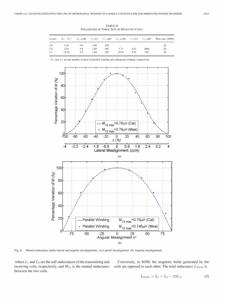
Fig. 6. Mutual inductance under lateral and angular misalignments. (a) Lateral misalignment. (b) Angular misalignment.
where L1 and L2 are the self-inductances of the transmitting andreceiving coils, respectively, and M12 is the mutual inductancebetween the two coils.
Conversely, in SOM, the magnetic fields generated by thecoils are opposed to each other. The total inductance LSOM is
LSOM = L1 + L2 − 2M12 . (5)
5636 IEEE TRANSACTIONS ON POWER ELECTRONICS, VOL. 30, NO. 10, OCTOBER 2015
By using (4) and (5), M12 can be determined by the measuredvalues of L1 and L2 , LSAM , and LSOM using the formulas of
M12 =12(LSAM − L1 − L2) (6)
or
M12 =12(L1 + L2 − LSOM). (7)
C. Mutual Inductance Under Lateraland Angular Misalignments
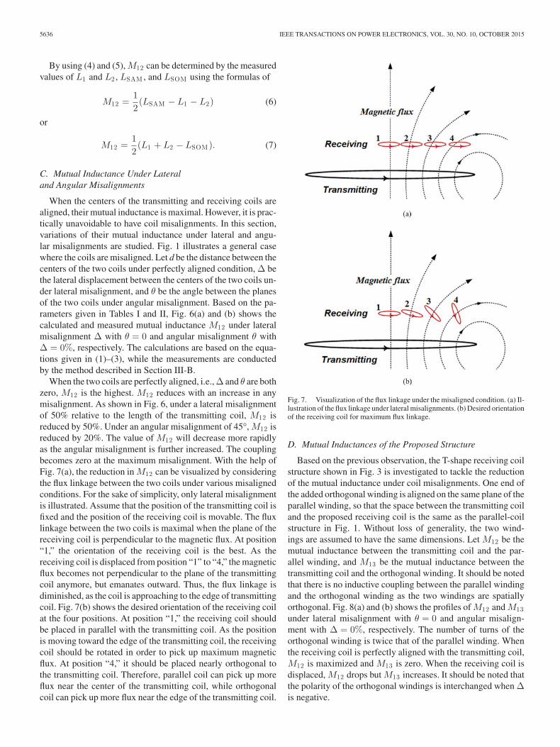
When the centers of the transmitting and receiving coils arealigned, their mutual inductance is maximal. However, it is prac-tically unavoidable to have coil misalignments. In this section,variations of their mutual inductance under lateral and angu-lar misalignments are studied. Fig. 1 illustrates a general casewhere the coils are misaligned. Let d be the distance between thecenters of the two coils under perfectly aligned condition, Δ bethe lateral displacement between the centers of the two coils un-der lateral misalignment, and θ be the angle between the planesof the two coils under angular misalignment. Based on the pa-rameters given in Tables I and II, Fig. 6(a) and (b) shows thecalculated and measured mutual inductance M12 under lateralmisalignment Δ with θ = 0 and angular misalignment θ withΔ = 0%, respectively. The calculations are based on the equa-tions given in (1)–(3), while the measurements are conductedby the method described in Section III-B.
When the two coils are perfectly aligned, i.e., Δ and θ are bothzero, M12 is the highest. M12 reduces with an increase in anymisalignment. As shown in Fig. 6, under a lateral misalignmentof 50% relative to the length of the transmitting coil, M12 isreduced by 50%. Under an angular misalignment of 45°, M12 isreduced by 20%. The value of M12 will decrease more rapidlyas the angular misalignment is further increased. The couplingbecomes zero at the maximum misalignment. With the help ofFig. 7(a), the reduction in M12 can be visualized by consideringthe flux linkage between the two coils under various misalignedconditions. For the sake of simplicity, only lateral misalignmentis illustrated. Assume that the position of the transmitting coil isfixed and the position of the receiving coil is movable. The fluxlinkage between the two coils is maximal when the plane of thereceiving coil is perpendicular to the magnetic flux. At position“1,” the orientation of the receiving coil is the best. As thereceiving coil is displaced from position “1” to “4,” the magneticflux becomes not perpendicular to the plane of the transmittingcoil anymore, but emanates outward. Thus, the flux linkage isdiminished, as the coil is approaching to the edge of transmittingcoil. Fig. 7(b) shows the desired orientation of the receiving coilat the four positions. At position “1,” the receiving coil shouldbe placed in parallel with the transmitting coil. As the positionis moving toward the edge of the transmitting coil, the receivingcoil should be rotated in order to pick up maximum magneticflux. At position “4,” it should be placed nearly orthogonal tothe transmitting coil. Therefore, parallel coil can pick up moreflux near the center of the transmitting coil, while orthogonalcoil can pick up more flux near the edge of the transmitting coil.
Fig. 7. Visualization of the flux linkage under the misaligned condition. (a) Il-lustration of the flux linkage under lateral misalignments. (b) Desired orientationof the receiving coil for maximum flux linkage.
D. Mutual Inductances of the Proposed Structure
Based on the previous observation, the T-shape receiving coilstructure shown in Fig. 3 is investigated to tackle the reductionof the mutual inductance under coil misalignments. One end ofthe added orthogonal winding is aligned on the same plane of theparallel winding, so that the space between the transmitting coiland the proposed receiving coil is the same as the parallel-coilstructure in Fig. 1. Without loss of generality, the two wind-ings are assumed to have the same dimensions. Let M12 be themutual inductance between the transmitting coil and the par-allel winding, and M13 be the mutual inductance between thetransmitting coil and the orthogonal winding. It should be notedthat there is no inductive coupling between the parallel windingand the orthogonal winding as the two windings are spatiallyorthogonal. Fig. 8(a) and (b) shows the profiles of M12 and M13under lateral misalignment with θ = 0 and angular misalign-ment with Δ = 0%, respectively. The number of turns of theorthogonal winding is twice that of the parallel winding. Whenthe receiving coil is perfectly aligned with the transmitting coil,M12 is maximized and M13 is zero. When the receiving coil isdisplaced, M12 drops but M13 increases. It should be noted thatthe polarity of the orthogonal windings is interchanged when Δis negative.

CHOW et al.: INVESTIGATION INTO THE USE OF ORTHOGONAL WINDING IN LOOSELY COUPLED LINK FOR IMPROVING POWER TRANSFER 5637
Fig. 8. Mutual inductance under lateral and angular misalignments. (a) Lateral Misalignment. (b) Angular misalignment.
IV. MODELING AND CIRCUIT IMPLEMENTATION
In order to maximize the utilization of the two windings inthe power transfer, they are energized concurrently by usinga current summing circuit. Such structure is studied by firstmodeling the windings with a proposed canonical transformermodel and then applying it to develop a circuit model to studythe overall power transfer phenomena.
A. Derivation of Canonical Transformer Model
A canonical transformer model that describes the interac-tion between the primary and secondary windings is derived.Fig. 9(a) shows the classical transformer model, in which thenumerals “1” and “2” appeared in the subscripts denote the pri-mary and secondary sides of the transformer, respectively. L and
r are the self-inductance and resistance of the respective wind-ing, respectively. The two windings have the turns ratio n12and mutual inductance M12 . Based on Fig. 9(a), the followingLaplace-transformed equations can be derived:
[V1(s)
V2(s)
]=
[sL1 + r1 −sM12
sM12 −(sL2 + r2)
] [I1(s)
I2(s)
]. (8)
Equation (8) is rearranged to derive a canonical model asfollows:
V1(s) =[Z1(s) +
sn212M12Z2(s)
n12Z2(s) + sM12
]I1(s) + n12Vd2(s)
(9)
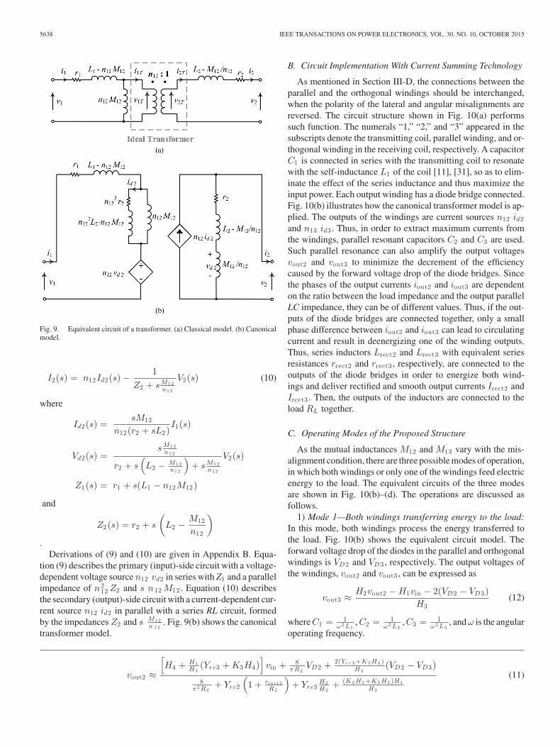
5638 IEEE TRANSACTIONS ON POWER ELECTRONICS, VOL. 30, NO. 10, OCTOBER 2015
Fig. 9. Equivalent circuit of a transformer. (a) Classical model. (b) Canonicalmodel.
I2(s) = n12Id2(s) −1
Z2 + sM 1 2n1 2
V2(s) (10)
where
Id2(s) =sM12
n12(r2 + sL2)I1(s)
Vd2(s) =sM 1 2
n1 2
r2 + s(L2 − M 1 2
n1 2
)+ sM 1 2
n1 2
V2(s)
Z1(s) = r1 + s(L1 − n12M12)
and
Z2(s) = r2 + s
(L2 −
M12
n12
)
.Derivations of (9) and (10) are given in Appendix B. Equa-
tion (9) describes the primary (input)-side circuit with a voltage-dependent voltage source n12 vd2 in series with Z1 and a parallelimpedance of n2
12 Z2 and s n12 M12 . Equation (10) describesthe secondary (output)-side circuit with a current-dependent cur-rent source n12 id2 in parallel with a series RL circuit, formedby the impedances Z2 and s M 1 2
n 1 2. Fig. 9(b) shows the canonical
transformer model.
B. Circuit Implementation With Current Summing Technology
As mentioned in Section III-D, the connections between theparallel and the orthogonal windings should be interchanged,when the polarity of the lateral and angular misalignments arereversed. The circuit structure shown in Fig. 10(a) performssuch function. The numerals “1,” “2,” and “3” appeared in thesubscripts denote the transmitting coil, parallel winding, and or-thogonal winding in the receiving coil, respectively. A capacitorC1 is connected in series with the transmitting coil to resonatewith the self-inductance L1 of the coil [11], [31], so as to elim-inate the effect of the series inductance and thus maximize theinput power. Each output winding has a diode bridge connected.Fig. 10(b) illustrates how the canonical transformer model is ap-plied. The outputs of the windings are current sources n12 id2and n13 id3 . Thus, in order to extract maximum currents fromthe windings, parallel resonant capacitors C2 and C3 are used.Such parallel resonance can also amplify the output voltagesvout2 and vout3 to minimize the decrement of the efficiencycaused by the forward voltage drop of the diode bridges. Sincethe phases of the output currents iout2 and iout3 are dependenton the ratio between the load impedance and the output parallelLC impedance, they can be of different values. Thus, if the out-puts of the diode bridges are connected together, only a smallphase difference between iout2 and iout3 can lead to circulatingcurrent and result in deenergizing one of the winding outputs.Thus, series inductors Lrect2 and Lrect3 with equivalent seriesresistances rrect2 and rrect3 , respectively, are connected to theoutputs of the diode bridges in order to energize both wind-ings and deliver rectified and smooth output currents Irect2 andIrect3 . Then, the outputs of the inductors are connected to theload RL together.
C. Operating Modes of the Proposed Structure
As the mutual inductances M12 and M13 vary with the mis-alignment condition, there are three possible modes of operation,in which both windings or only one of the windings feed electricenergy to the load. The equivalent circuits of the three modesare shown in Fig. 10(b)–(d). The operations are discussed asfollows.
1) Mode 1—Both windings transferring energy to the load:In this mode, both windings process the energy transferred tothe load. Fig. 10(b) shows the equivalent circuit model. Theforward voltage drop of the diodes in the parallel and orthogonalwindings is VD2 and VD3 , respectively. The output voltages ofthe windings, vout2 and vout3 , can be expressed as
vout3 ≈ H2vout2 − H1vin − 2(VD2 − VD3)H3
(12)
where C1 = 1ω 2 L1
, C2 = 1ω 2 L2
, C3 = 1ω 2 L3
, and ω is the angularoperating frequency.
vout2 ≈
[H4 + H1
H3(Yrc3 + K3H4)
]vin + 8
πRLVD2 + 2(Yr c 3 +K 3 H4 )
H3(VD2 − VD3)
8π 2 RL
+ Yrc2
(1 + rr e c t 2
RL
)+ Yrc3
H2H3
+ (K 2 H3 +K 3 H2 )H4H3
(11)

CHOW et al.: INVESTIGATION INTO THE USE OF ORTHOGONAL WINDING IN LOOSELY COUPLED LINK FOR IMPROVING POWER TRANSFER 5639
Fig. 10. Circuit implementation and equivalent circuits in the three operating modes. (a) Proposed circuit implementation. (b) Equivalent circuit in Mode 1operation. (c) Equivalent circuit in Mode 2 operation. (d) Equivalent circuit in Mode 3 operation.
Derivations of (11) as shown bottom of the previous page and(12), and definition of the parameters are given in Appendix C.If the dc resistances of the series inductors, rrect2 and rrect3 , aremuch smaller than the load resistance RL , and VD2 and VD3 areassumed to be the same, rrect2 = rrect3 = 0 and VD2 = VD3 =VD . Equations (11) and (12) can be simplified as
vout2 ≈K 2 +K 3
K 1vin + 8
πRLVD
8π 2 RL
+ Yrs2 + Yrs3 + (K 2 +K 3 )2
K 1
(13)
vout3 = vout2 = vout . (14)
The average load voltage VL and the input current iin are
VL =2π
Vout,pk − 2VD (15)
iin =vin − (K2 + K3)vout2
K1(16)
where Vout,pk is the amplitude of vout .2) Mode 2—Only parallel winding transferring energy to the
load: This mode occurs when the transmitting coil and the par-allel winding are near to the aligned condition. Fig. 10(c) showsthe equivalent circuit model. vout2 and vout3 can be expressedas
vout2 ≈K 2 Yr c 3
K 1 Yr c 3 +K 23vin + 8
π (RL +rr e c t 2 ) VD
8π 2 (RL +rr e c t 2 ) + K 2
2 Yr c 3
K 1 Yr c 3 +K 23
+ Yrc2
(17)
vout3 =K3vin − K2K3vout2
K1Yrc3 + K23
. (18)
Derivations of (17) and (18), and definition of the parametersare given in Appendixes C and D
VL =RL
RL + rrect2
(2π
Vout2,pk − 2VD
)(19)
iin =vin − K2vout2 − K3vout3
K1(20)
where Vout2,pk is the amplitude of vout2 .3) Mode 3—Only orthogonal winding transferring energy
to the load: This mode occurs when the transmitting coil andthe parallel winding are significantly misaligned. Fig. 10(d)shows the equivalent circuit model. vout2 , vout3 , and VL can beexpressed as
vout2 =K2vin − K2K3vout3
K1Yrc2 + K22
(21)
vout3 ≈K 3 Yr c 2
K 1 Yr c 2 +K 22vin + 8
π (RL +rr e c t 3 ) VD
8π 2 (RL +rr e c t 3 ) + K 2
3 Yr c 2
K 1 Yr c 2 +K 22
+ Yrc3
(22)
VL =RL
RL + rrect3
(2π
Vout3,pk − 2VD
)(23)
where Vout3,pk is the amplitude of vout3 .The input current iin in this mode has the same expression
as (20).

5640 IEEE TRANSACTIONS ON POWER ELECTRONICS, VOL. 30, NO. 10, OCTOBER 2015
D. Boundary Conditions for Determining theOperating Modes
The operating mode of the proposed circuit is determined bythe ratio between k12 and k13 , where k12 is the coupling coef-ficient between the transmitting coil and the parallel winding,and k13 is the coupling coefficient between the transmitting coiland the orthogonal winding.
In the Mode 1 operation
iout2 > 0 and iout3 > 0. (24)
In the Mode 2 operation
iout2 > 0 and iout3 = 0. (25)
In the Mode 3 operation
iout2 = 0 and iout3 > 0. (26)
The boundary between Modes 1 and 2 is determined by theconditions
vout2 = vout3 (27)
and
iout3 = 0. (28)
Define
Ψ =k12
k13. (29)
Based on (17) and (18), the circuit will be in Mode 2 operationif
Ψ ≥ (ΨM 1−M 2)−1 (30)
where ΨM 1−M 2 = 1Q 3
[1
Q 2− 8 r 2
π 2 R L(1+Q 2 )
]√
L2L3
.
The expression and derivation of ΨM 1−M 2 are given in Ap-pendix E.
Similarly, the boundary between Modes 1 and 3 is determinedby the conditions
vout2 = vout3 (31)
and
iout2 = 0. (32)
Based on (21) and (22), the circuit will be in Mode 3 operationif
Ψ ≤ ΨM 1−M 3 (33)
where ΨM 1−M 3 = 1Q 2
[1
Q 3− 8 r 3
π 2 R L(1+Q 3 )
]√
L3L2
.
Derivation of ΨM 1−M 3 is similar to the derivation ofΨM 1−M 2 in Appendix E, under the condition that vout2 = vout3and iout2 = 0.
Fig. 11 shows the boundaries for the three modes on thek12−k13 plane with three different turns-ratios between theparallel and orthogonal windings. They are 12:6, 12:12, and12:24. Thus, both windings are concurrently energized within a
Fig. 11. Mode of operation on the k12 −k13 plane. (a) N2 : N3 = 12 : 6. (b)N2 : N3 = 12 : 12. (c) N2 : N3 = 12 : 24.
wide range of coupling coefficient (i.e., in Mode 1 operation).The regions covered by Modes 2 and 3 is determined by thevalues of L2 and L3 . When L3 > L2 , the area covered by Mode3 is more than that covered by Mode 2, and vice versa. Forexample, as shown in Fig. 11(a), N2 : N3 = 12 : 26, the areacovered by Mode 2 is larger than the area covered by Mode 3.Conversely, as shown in Fig. 11(c), N2 : N3 = 12 : 24, the areacovered by Mode 3 is larger than that by Mode 2.

CHOW et al.: INVESTIGATION INTO THE USE OF ORTHOGONAL WINDING IN LOOSELY COUPLED LINK FOR IMPROVING POWER TRANSFER 5641
V. POWER TRANSFER EFFICIENCY
The power transfer efficiencies of the parallel coils and theproposed structure are studied and compared. As shown inFig. 1, the power transfer efficiency η is calculated by
η =Pout
Pin=
V 2L /RL
Re[viniin∗](34)
where Pout is the output power to the load RL , Pin is the inputpower to the transmitting coil, i∗n is the conjugate of iin , andRe[viniin∗] means the real part.
Based on the dimensions, positions, orientations, and numberof turns of the coils, the mutual inductances M12 and M13 areobtained by using (3). The coupling coefficients k12 and k13 aredetermined by using the equations
k12 =M12√L1L2
(35)
and
k13 =M13√L1L3
. (36)
The mode of operation is located by using the values of k12and k13 on the k12−k13 plane in Fig. 11. Then, the optimalload resistance RL,optimal is determined by using an iterativemethod. Fig. 12 shows the flowchart. The steps are described asfollows:
1) choose the magnitudes of the lateral misalignment Δ andangular misalignment θ;
2) calculate M12 and M13 with (3), and determine the cor-responding values of k12 and k13 with (35) and (36),respectively;
3) select an initial value of RL , e.g., 100 Ω, and set n = 1;4) calculate Ψ with (29);5) calculate ΨM 1−M 2 and ΨM 1−M 3 with (30) and (33),
respectively;6) determine the mode of operation, based on the criteria
given in Section IV-D;7) calculate the values of VL and iin with the required set
of equations, (11)–(16) for Mode 1, (17)–(20) for Mode2, and (20)–(23) for Mode 3;
8) calculate η (n) with (34) and compare it with η(n − 1);9) terminate the iteration with RL,optimal = RL (n) for the
efficiency η at the considered misalignment if |η(n) −η(n − 1)| < εT , and start from Step 1 with a new mis-alignment;
10) if not, increase the value RL by ΔRL , increment n, andrepeat from Step 5.
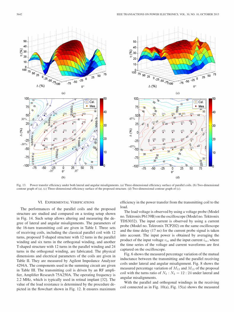
Fig. 13(a) shows the 3-D surface of the power transfer effi-ciency versus different combinations of Δ and θ of classical par-allel coils. Fig. 13(b) shows the 2-D contour graph of Fig. 13(a).Fig. 13(c) and (d) shows the power transfer efficiency of theproposed coil structure with the windings having the turns ratioof N2 : N3 = 12 : 24. The physical dimensions and electricalparameters of the transmitting coil and receiving coil are givenin Tables I and II. As shown in Fig. 13(a), the efficiency sur-face of the parallel coils is like a “rugby ball.” The rate ofreduction of the efficiency versus lateral or angular misalign-
Fig. 12. Flowchart for calculating RL,optim al and η.
ment becomes more severe when the efficiency is in the rangeof 30%, since the contour lines start getting closer from thisrange. The minimum efficiency is 0%, where the two coils aresignificantly misaligned. If the minimum efficiency consideredis 30%, the maximum allowable lateral misalignment Δ rangesfrom −30% to +30% and angular misalignment θ ranges from−35° to +35°. Such zone is shaded in Fig. 13(b).
The efficiency surface of the proposed structure shown inFig. 13(c) is more uniform and no abrupt efficiency drop isobserved. Again, if the minimum efficiency of 30% is needed,the maximum allowable lateral misalignment Δ ranges from−45% to +45%. The efficiency is always higher than 30% overthe range of the angular misalignment. Such zone is shaded inFig. 13(d). Thus, the misalignment tolerance of the proposedstructure is better than the parallel coils.
5642 IEEE TRANSACTIONS ON POWER ELECTRONICS, VOL. 30, NO. 10, OCTOBER 2015
Fig. 13. Power transfer efficiency under both lateral and angular misalignments. (a) Three-dimensional efficiency surface of parallel coils. (b) Two-dimensionalcontour graph of (a). (c) Three-dimensional efficiency surface of the proposed structure. (d) Two-dimensional contour graph of (c).
VI. EXPERIMENTAL VERIFICATIONS
The performances of the parallel coils and the proposedstructure are studied and compared on a testing setup shownin Fig. 14. Such setup allows altering and measuring the de-gree of lateral and angular misalignments. The parameters ofthe 16-turn transmitting coil are given in Table I. Three setsof receiving coils, including the classical parallel coil with 12turns, proposed T-shaped structure with 12 turns in the parallelwinding and six turns in the orthogonal winding, and anotherT-shaped structure with 12 turns in the parallel winding and 24turns in the orthogonal winding, are fabricated. The physicaldimensions and electrical parameters of the coils are given inTable II. They are measured by Agilent Impedance Analyzer4294A. The components used in the summing circuit are givenin Table III. The transmitting coil is driven by an RF ampli-fier, Amplifier Research 75A250A. The operating frequency is2.2 MHz, which is typically used in retinal implant [32]. Thevalue of the load resistance is determined by the procedure de-picted in the flowchart shown in Fig. 12. It ensures maximum
efficiency in the power transfer from the transmitting coil to theload.
The load voltage is observed by using a voltage probe (Modelno. Tektronix P6139B) on the oscilloscope (Model no. TektronixTDS3032). The input current is observed by using a currentprobe (Model no. Tektronix TCP202) on the same oscilloscopeand the time delay (17 ns) for the current probe signal is takeninto account. The input power is obtained by averaging theproduct of the input voltage vin and the input current iin , wherethe time series of the voltage and current waveforms are firstcaptured on the oscilloscope.
Fig. 6 shows the measured percentage variation of the mutualinductance between the transmitting and the parallel receivingcoils under lateral and angular misalignment. Fig. 8 shows themeasured percentage variation of M12 and M13 of the proposalcoil with the turns ratio of N2 : N3 = 12 : 24 under lateral andangular misalignments.
With the parallel and orthogonal windings in the receivingcoil connected as in Fig. 10(a), Fig. 15(a) shows the measured

CHOW et al.: INVESTIGATION INTO THE USE OF ORTHOGONAL WINDING IN LOOSELY COUPLED LINK FOR IMPROVING POWER TRANSFER 5643
Fig. 14. Experimental setup. (a) Aligned condition. (b) Lateral misalignment.(c) Angular misalignment.
transfer efficiency of the three testing receiving coils under lat-eral misalignment with θ = 0. Fig. 15(b) shows the measuredresults under angular misalignment with Δ = 0%. The rangesof the operating modes are marked on the graphs.
Fig. 13(b) shows the measured efficiencies with the parallelreceiving coil oriented at 25 combinations of lateral and angularmisalignments. The lateral alignment is ranged from −50% to+50%, while the angular misalignment is ranged from −50° to+50°. Similarly, Fig. 13(d) shows the measured efficiencies withthe T-shaped structure with the turns ratio of N2 : N3 = 12 : 24at the same orientations measured in Fig. 13(b). The theoreticalpredictions shown on the contours are close to the experimentalresults.
TABLE IIICOMPONENT VALUES OF THE OUTPUT CURRENT SUMMING CIRCUIT
v in , p e a k D2 i ∼ D3 i ∗ L r e c t 2 and L r e c t 3 rr e c t 2 and rr e c t 3
5 V 1N4148 0.92 mH 15.0 Ω
∗i = 1–4.
A power loss audit of three cases in the three modes has beenconducted. The results are shown in Table IV. It was foundthat the major loss is in the winding resistances. Thus, if theoperating frequency is increased, the power loss in the windingswill increase as the ac resistance of the windings will increase,due to the skin effect and proximity effects [28].
Fig. 16 shows the waveforms of iout2 , iout3 , and IL under dif-ferent combinations of lateral and angular misalignments withiout2 : iout3 = 6 : 1, 1 : 1, and 1 : 6. IL is found to be the sumof the rectified value of iout2 and iout3 in all cases, confirmingthe current summing technique. The waveforms of iout2 andiout3 are near square waveform, confirming the modeling of thecorresponding current sources given in Section IV.
VII. OBSERVATIONS AND DISCUSSIONS
Based on the theoretical analysis and experimental results,some observations are made and future investigations are sug-gested.
1) Based on Figs. 13 and 15, it is confirmed that the orthogo-nal winding can effectively improve the transfer efficiencyunder coil misalignment. Thus, more orthogonal windingscan be added to form complex loosely coupled windingstructures. For example, a second orthogonal winding canbe added onto the receiving coil. Then, the structure cantackle misalignment of a higher dimension. As the anal-ysis method discussed in this paper starts from the basicprinciple, similar analysis can be adopted for studying thestructure with the second orthogonal winding.
2) Compared Fig. 13(a) with Fig. 13(c), the overall transferefficiency of the proposed structure will never go to zerowithin the considered range of the misalignments, becauseeither one or both of the windings will have coupling withthe transmitting coil. Conversely, the classical parallel coilcould have zero efficiency.
3) The canonical transformer model presented in Section IVgives an alternative circuit model to study the couplingphenomenon of windings. Experimental results confirmthe validity of the circuit model. Since the output windingis modeled as a current source in parallel with an induc-tance, it is suitable for modeling complex structures withseveral parallel windings.
4) The current summing technique with the added outputinductors Lrect2 and Lrect3 , shown in Fig. 10(a), can keepboth windings energized to deliver power to the load. Asshown in Fig. 11, except under extreme low values of thecoupling coefficients k12 and k13 , the entire circuit willoperated in Mode 1, that is, both windings transfer energyto the load.

5644 IEEE TRANSACTIONS ON POWER ELECTRONICS, VOL. 30, NO. 10, OCTOBER 2015
TABLE IVPOWER LOSS AUDIT IN THE THREE MODES
Mode P in (mW) Po u t (mW) Loss of r ∗1 (%) Loss of r ∗
2 (%) Loss of r ∗3 (%) Loss of the diode bridges∗ (%) Loss of r ∗
r e c t 2 and r ∗r e c t 3 (%)
I 896 330 41.11 15.38 3.11 3.23 0.34II 619 304 27.51 17.95 0.00 4.56 0.87III 1448 173 75.46 2.31 9.61 0.66 0.02
∗The losses are all normalized by the input power P i n .
Fig. 15. Measured power transfer efficiency of different coil sets with parallel and orthogonal windings under lateral and angular misalignments. (a) Efficiencycurves under lateral misalignment. (b) Efficiency curves under angular misalignment.
5) As shown in Fig. 15, when the circuit is in Mode 2 op-eration, the transfer efficiency of the proposed structureis lower than with just the parallel coil. As shown inFig. 10(c), it is mainly because a small amount of en-ergy is dissipated in the orthogonal winding. In order toreduce the difference, the range of Mode 2 operation canbe reduced by increasing the number of turns of the or-thogonal winding. As shown in Fig. 15 (from green lineto blue line), with the number of turns in the orthogonal
winding increasing from 6 to 24, the range of the Mode2 operation is reduced. As exemplified in Fig. 15, withthe number of turns increased from 6 turns to 24 turns,the difference in the transfer efficiency is reduced from9% to 1.7% in the lateral misalignment and from 10%to 1.7% in the angular misalignment. Such phenomenoncan be explained by considering that the impedance ofthe orthogonal winding is increased. Thus, the currentthrough the winding, and thus its power loss, are reduced.

CHOW et al.: INVESTIGATION INTO THE USE OF ORTHOGONAL WINDING IN LOOSELY COUPLED LINK FOR IMPROVING POWER TRANSFER 5645
Fig. 16. Waveforms of iout2 , iout3 , and IL under different misalignments[Ch2: iout2 , Ch3: iout3 , Ch4: IL (50 mA/div)] (Timebase: 200 ns/div). (a)iout2 : iout3 = 6 : 1. (b) iout2 : iout3 = 1 : 1. (c) iout2 : iout3 = 1 : 6.
However, the number of turns cannot be continually in-creased, as there is a maximum achievable efficiency, sim-ilar to the characteristics of the parallel coil shown inFig. 2. The difference of 1.7% is acceptable in practice, asthere is a significant improvement in the efficiency undercoil misalignment.
6) The efficiency drop issue discussed in item (5) may besolved by using a circuit to disable the orthogonal windingupon Mode 2 operation, such as the method discussed in[26]. However, special consideration should be given tothe increase of the circuit complexity.
7) As shown in Fig. 15, when the circuit is in Mode 3 op-eration, the orthogonal winding takes up the main energytransfer. Since the coupling of the transmitting coil andthe orthogonal winding is good, the transfer efficiencywill increase abruptly.
Fig. 17. Illustration of the application of the proposed winding structure.
8) It is understandable that the orthogonal winding can beplaced in the transmitting coil and the receiving coil is aparallel winding. Driving of the transmitting coil can besimilar to the one described in [8] and [24]. More complexwinding structures can also be deduced.
9) Fig. 17 shows a model illustrating how the proposed struc-ture can be placed inside an eyeball for a visual prosthe-sis [33], [34]. Electric power can be transmitted fromthe glasses. Complex structures can also be deduced forapplications, like capsular endoscope, requiring dealingwith high-dimension misalignment. Further investigationscan be emphasized on the relationships among the op-erating frequency, coil size, and space constraint of theapplication.
VIII. CONCLUSION
A comprehensive investigation into the use of an orthogonalwinding in loosely coupled link for enhancing transfer effi-ciency under coil misalignment has been presented. Both theo-retical and experimental results confirm that the power transferefficiency under coil misalignment can be effectively increasedwith the added orthogonal winding. A canonical transformermodel has been derived and applied to study the proposed struc-ture. Moreover, a current summing technique has been proposedto energize the parallel and orthogonal windings over a widerange of misalignments. The concept has been verified on a testbed.
APPENDIX AEXPRESSIONS OF THE PARAMETERS IN (2)
BD = R1 , BC = R2 , AC = R3 , AD = R4 , cos ε =α2
2lm,
α2 = R24 − R2
3 + R22 − R2
1 ,

5646 IEEE TRANSACTIONS ON POWER ELECTRONICS, VOL. 30, NO. 10, OCTOBER 2015
d2 = R2
3 − μ2 − ν2 + 2μν cos ε,
μ =l[2m2(R2
2 − R23 − l2) + α2(R2
4 − R23 − m2)]
4l2m2 − α4 ,
ν =m[2l2(R2
4 − R23 − m2) + α2(R2
2 − R23 − l2)]
4l2m2 − α4
and
Ω = tan−1[d2 cos ε + (μ + l)(ν + m) sin2 ε
d R1 sin ε
]
− tan−1[d2 cos ε + (μ + l) ν sin2 ε
d R2 sin ε
]
+ tan−1[d2 cos ε + μ ν sin2 ε
d R3 sin ε
]
− tan−1[d2 cos ε + μ(ν + m) sin2 ε
d R4 sin ε
].
APPENDIX BDERIVATION OF (9) AND (10)
Based on Fig. 9(a), the ideal transformer has the primary-sidevoltage v1 T and current i1 T , and the secondary-side voltagev2T and current i2T . Thus,
V1T (s) = n12V2T (s) (B1)
V1T (s) = sn12M [I1(s) − I1T (s)] (B2)
V2T (s)=[r2 + s
(L2 −
M
n12
)]I2T (s) + V2(s)
(B3)
sM [I1(s) − I1T (s)]=[r2 + s
(L2 −
M
n12
)]I2T (s) + V2(s)
I1T (s) =I2T (s)n12
I2(s) =sM
r2 + sL2I1(s)
− 1
r2 + s(L2 − M
n1 2
)+ s M
n1 2
V2(s).
(B4)
By substituting (B6) into (B3) and (B1)
V1T (s) =s M
n1 2
[r2 + s
(L2 − M
n1 2
)]
r2 + s(L2 − M
n1 2
)+ s M
n1 2
n212I1(s)
+s M
n1 2
r2 + s(L2 − M
n1 2
)+ s M
n1 2
n12V2(s) (B7)
V1(s) = {r1 + s(L1 − n12M)
+sn12M
[n2
12r2 + sn212
(L2 − M
n1 2
)]
n212r2 + sn2
12
(L2 − M
n1 2
)+ sn12M
⎫⎬⎭ I1(s) (B8)
+s M
n1 2
r2 + s(L2 − M
n1 2
)+ s M
n1 2
n12V2(s). (B9)
APPENDIX CDERIVATIONS OF (11) AND (12)
Let
K1 = r1 + jωL1 +1
jωC1
− (jωM12)2
r2 + jωL2− (jωM13)2
r3 + jωL3
K2 =jωM12
r2 + jωL2
K3 =jωM13
r3 + jωL3
n12vd2 = K2vout2 , n13vd3 = K3vout3 (C1)
iin =vin − K2vout2 − K3vout3
K1(C2)
n12id2 = K2iin , n13id3 = K3iin . (C3)
The admittances of the receiving parallel resonant circuits,Yrc2 and Yrc3 , are
Yrc2 =1 + jωC2(r2 + jωL2)
r2 + jωL2
Yrc3 =1 + jωC3(r3 + jωL3)
r3 + jωL3.
When the inductance of Lrect2 and Lrect3 are large enough,Irect2 and Irect3 can be considered as constant dc current, so thecurrent input to the rectifier iout2 and iout3 should be in form ofsquare wave. The fundamental current components are
iout2 = n12id2 − Yrc2vout2 , iout3 = n13id3 − Yrc3vout3
(C4)
|iout2 | =π
4iout2,peak , |iout3 | =
π
4iout3,peak . (C5)
By combining (C1)–(C5)
Irect2 = |iout2 | =π
4
[K2
K1(vin − K2vout2
− K3vout3) − Yrc2vout2
],peak
(C6)
Irect3 = |iout3 | =π
4
[K3
K1(vin − K2vout2
− K3vout3) − Yrc3vout3
],peak
(C7)
V rect2 =2π
vout2,peak − 2VD2 , Vrect3 =2π
vout3,peak − 2VD3
(C8)
VL = V rect2 − Irect2rrect2 , VL = V rect3 − Irect3rrect3 .
(C9)

CHOW et al.: INVESTIGATION INTO THE USE OF ORTHOGONAL WINDING IN LOOSELY COUPLED LINK FOR IMPROVING POWER TRANSFER 5647
By combining (C6)–(C9)
2π
vout2,peak − 2VD2 −π
4iout2,peakrrect2
=2π
vout3,peak − 2VD3 −π
4iout3,peakrrect3 . (C10)
When ωLrect2 and ωLrect3 are larger than the load resistanceRL , vout2 and vout3 are in the same phase ϕ
2π
vout2 − 2VD2∠φ − π
4iout2rrect2
=2π
vout3 − 2VD3∠φ − π
4iout3rrect3
vout3 =H2vout2 − H1vin − 2(VD2 − VD3)∠φ
H3(C11)
where
H1 =π
4(K2rrect2 − K3rrect3)
K1
H2 =2π
+π
4
[K2(K2rrect2 − K3rrect3)
K1+ Yrc2rrect2
]
H3 =2π
+π
4
[K3(K3rrect3 − K2rrect2)
K1+ Yrc3rrect3
]
VL = Vrect2 − Irect2rrect2 = (Irect2 + Irect3)RL. (C12)
By substituting (C5) to (C8) into (C12), (C13) as shown at the
bottom of the page, where H4 = 1K 1
[K2
(1 + rr e c t 2
RL
)+ K3
].
Since C1 , C2 , and C3 resonate with the respective winding self-inductance, the phase angle of the output voltages ϕ is nearzero.
APPENDIX DDERIVATIONS OF (17) AND (18)
n13id3 = Yrc3vout3 (D1)
n13id3 = K3
(vin − K2vout2 − K3vout3
K1
). (D2)
By combining (D1) and (D2)
vout3 =K3vin − K2K3vout2
K1Yrc3 + K23
(D3)
Irect2 = |iout2 | =π
4
[K2
K1(vin (D4)
− K2vout2 − K3vout3) − Yrc2vout2
],peak
VL =2π
vout2,peak − 2VD2 − Irect2rrect2 = Irect2RL.
(D5)
By combining (D3) and (D5)
vout2 =K 2 Yr c 3
K 1 Yr c 3 +K 23vin + 8
π (RL +rr e c t 2 ) VD2∠φ
8π 2 (RL +rr e c t 2 ) + K 2
2 Yr c 3
K 1 Yr c 3 +K 23
+ Yrc2
. (D6)
Since C1 and C2 resonate with the respective winding self-inductance, the phase angle of vout2 ϕ can be considered aszero.
APPENDIX EDERIVATION OF (30)
For the sake of simplicity, VD2 , VD3 , rrect2 , and rrect3 areneglected. Then
vout2 = vout3 = vout (E1)
iout3 = 0 (E2)
n12id2 =K2
K1[vin − (K2 + K3)vout] ,
n13id3 =K3
K1[vin − (K2 + K3)vout] (E3)
Irect2 = |iout2 | =π
4[n12id2 − Yrc2vout],peak (E4)
VL =2π
vout,peak = Irect2RL. (E5)
By combining (E3)–(E5)
vout =K 2K 1
vin
8π 2 RL
+ K 2 (K 2 +K 3 )K 1
+ Yrc2(E6)
n13id3 = Yrc3vout . (E7)
By combining (E3)–(E7)
vout =K 3K 1
vin
K 3 (K 2 +K 3 )K 1
+ Yrc3. (E8)
By substituting (E6) into (E8)
K 2K 1
vin
8π 2 RL
+ K 2 (K 2 +K 3 )K 1
+ Yrc2=
K 3K 1
vin
K 3 (K 2 +K 3 )K 1
+ Yrc3
2π
vout2,peak − 2VD2 −π
4iout2,peakrrect2 =
π
4(iout2,peak + iout3,peak)RL
2π
vout2 − 2VD2∠φ − π
4iout2rrect2 =
π
4(iout2 + iout3)RL
vout2 =
[H4 + H1
H3(Yrc3 + K3H4)
]vin + 8
πRLVD2∠φ + 2(Yr c 3 +K 3 H4 )
H3(VD2 − VD3)∠φ
8π 2 RL
+ Yrc2
(1 + rr e c t 2
RL
)+ Yrc3
H2H3
+ (K 2 H3 +K 3 H2 )H4H3
(C13)

5648 IEEE TRANSACTIONS ON POWER ELECTRONICS, VOL. 30, NO. 10, OCTOBER 2015
K3
K2=
Yrc3
Yrc2 + 8π 2 RL
. (E9)
By substituting K2 and K3 into (E9)
M13
M12=
1
Q3
[1
Q 2− 8r2
π 2 RL(1 + Q2)
] (E10)
where Q2 = jωL2r2
and Q3 = jωL3r3
.M12 and M13 can be expressed in term of their corresponding
coupling coefficient k12 and k13
M12 = k12
√L1L2 and M13 = k13
√L1L3 . (E11)
By combining (E10) and (E11)
ΨM 1−M 2 =k13
k12|vo u t 2 =vo u t 3 , io u t 3 =0
=M13
M12
√L2
L3|vo u t 2 =vo u t 3 , io u t 3 =0
=1
Q3
[1
Q 2− 8 r2
π 2 RL(1 + Q2)
]√
L2
L3. (E12)
REFERENCES
[1] F. A. Spelman, “The past, present, and future of cochlear prostheses,”IEEE Eng. Med. Biol. Mag., vol. 18, no. 3, pp. 27–33, May/Jun. 1999.
[2] J. M. Ong and L. da Cruz, “The bionic eye: A review,” Clin. Exp. Oph-thalmol., vol. 40, no. 1, pp. 6–17, 2012.
[3] W. Li, “Integrated retinal implants,” Ph.D. dissertation, Dept. Eng. Appl.Sci., California Inst. Technol., Pasadena, CA, USA, 2009.
[4] D. Ng, S. Bai, J. Yang, N. Tran, and E. Skafidas, “Wireless technologiesfor closed-loop retinal prostheses,” J. Neural Eng., vol. 6, art. no. 65004,2009, doi:10.1088/1741-2560/6/6/065004.
[5] W. C. Ho, C. K. Lee, S. Y. R. Hui, and H. Chung, “Electronic controlmethod for a planar inductive battery charging apparatus,” US Patent8 228 025, Jul. 24, 2012.
[6] G. A. Covic and J. T. Boys, “Modern trends in inductive power transfer fortransportation applications,” IEEE J. Emerg. Sel. Topics Power Electron.,vol. 1, no. 1, pp. 28–41, Mar. 2013.
[7] J. Huh, S. W. Lee, W. Y. Lee, G. H. Cho, and C. T. Rim, “Narrow-width inductive power transfer system for online electrical vehi-cles,” IEEE Trans. Power Electron., vol. 26, no. 12, pp. 3666–3679,Dec. 2011.
[8] H. N. Pham, H. Fujita, K. Ozaki, and N. Uchida, “Estimating method ofheat distribution using 3-D resistance matrix for zone-control inductionheating systems,” IEEE Trans. Power Electron., vol. 27, no. 7, pp. 3374–3382, Jul. 2012.
[9] W. H. Ko, S. P. Liang, and C. D. Fung, “Design of radio-frequency poweredcoils for implant instruments,” Med. Biol. Eng. Comput., vol. 15, no. 6,pp. 634–640, Nov. 1977.
[10] K. M. Silay, D. Dondi, L. Larcher, M. Declercq, L. Benini, Y. Leblebici,and C. Dehollain, “Load optimization of an inductive power link for remotepowering of biomedical implants,” in Proc. IEEE Int. Symp. Circuits Syst.,2009, pp. 533–536.
[11] W. Zhang, S. C. Wong, C. K. Tse, and Q. Chen, “Analysis and comparisonof secondary series- and parallel-compensated inductive power transfersystems operating for optimal efficiency and load-independent voltage-transfer ratio,” IEEE Trans. Power Electron., vol. 29, no. 6, pp. 2979–2990,Jun. 2014.
[12] D. Yates, A. Holmes, and A. Burdett, “Optimal transmission frequencyfor ultralow-power short-range radio links,” IEEE Trans. Circuits Syst. I,Reg. Papers, vol. 51, no. 7, pp. 1405–1413, Jul. 2004.
[13] M. Pinuela, D. Yates, S. Lucyszyn, and P. Mitcheson, “Maximizing DC-to-load efficiency for inductive power transfer,” IEEE Trans. Power Electron.,vol. 28, no. 5, pp. 2437–2447, May 2013.
[14] K. Fotopoulou and B. Flynn, “Wireless power transfer in loosely coupledlinks: Coil misalignment model,” IEEE Trans. Magn., vol. 47, no. 2, pp.416–430, Feb. 2011.
[15] R. Puers, K. van Schuylenbergh, M. Catrysse, and B. Herman, “Wirelessinductive transfer of power and data,” in Analog Circuit Design. NewYork, NY, USA: Springer, 2006, pp. 395–414.
[16] B. Cannon, J. Hoburg, D. Stancil, and S. Goldstein, “Magnetic resonantcoupling as a potential means for wireless power transfer to multiple smallreceivers,” IEEE Trans. Power Electron., vol. 24, no. 7, pp. 1819–1825,Jul. 2009.
[17] X. Liu and S. Hui, “Optimal design of a hybrid windings structure for pla-nar contactless battery charging platform,” IEEE Trans. Power Electron.,vol. 23, no. 1, pp. 455–463, Jan. 2008.
[18] P. Raval, D. Kacprzak, and A. Hu, “Chapter 7: Technology overview andconcept of wireless charging systems,” in Wireless Power Transfer, J. I.Agbinya, Ed. Aalborg, Denmark: River Publishers, 2012.
[19] B. Lenaerts and R. Puers, “Chapter 5: Omnidirectional coupling,” in Om-nidirectional Inductive Powering for Biomedical Implants. New York, NY,USA: Springer Sci., 2009.
[20] A. RamRakhyani, S. Mirabbasi, and M. Chiao, “Design and optimizationof resonance-based efficient wireless power delivery systems for biomedi-cal implants,” IEEE Trans. Biomed. Circuits Syst., vol. 5, no. 1, pp. 48–63,Feb. 2011.
[21] M. Kiani, U. Jow, and M. Ghovanloo, “Design and optimizationof a 3-coil inductive link for efficient wireless power transmission,”IEEE Trans. Biomed. Circuits Syst., vol. 5, no. 6, pp. 579–591,Dec. 2011.
[22] A. K. RamRakhyani and G. Lazzi, “On the design of efficient multi-coiltelemetry system for biomedical implants,” IEEE Trans. Biomed. CircuitsSyst., vol. 7, no. 1, pp. 11–23, Feb. 2013.
[23] M. Ghovanloo and S. Atluri, “A wide-band power-efficient inductive wire-less link for implantable microelectronic devices using multiple carriers,”IEEE Trans. Circuits Syst. I, Reg. Papers, vol. 54, no. 10, pp. 2211–2221,Oct. 2007.
[24] H. Matsumoto, Y. Neba, K. Ishizaka, and R. Itoh, “Model for a three-phasecontactless power transfer system,” IEEE Trans. Power Electron., vol. 26,no. 9, pp. 2676–2687, Sep. 2011.
[25] J. P. C Smeets, T. T. Overboom, J. W. Jansen, and E. A. Lomonova,“Comparison of position-independent contactless energy transfer sys-tems,” IEEE Trans. Power Electron., vol. 28, no. 4, pp. 2059–2067, Apr.2013.
[26] S. Raabe and G. Covic, “Practical design considerations for contactlesspower transfer quadrature pick-ups,” IEEE Trans. Ind. Electron., vol. 60,no. 1, pp. 400–408, Jan. 2013.
[27] A. Zaheer, G. Covic, and D. Kacprzak, “A bipolar pad in a 10-kHz 300Wdistributed IPT system for AGV applications,” IEEE Trans. Ind. Electron.,vol. 61, no. 7, pp. 3288–3301, Jul. 2013.
[28] M. A. Bahmani, T. Thiringer, and H. Ortega, “An accurate pseudoempir-ical model of winding loss calculation in HF foil and round conductors inswitchmode magnetics,” IEEE Trans. Power Electron., vol. 29, no. 8, pp.4231–4246, Oct. 2013.
[29] J. Chow, N. Chen, H. Chung, and L. Chan, “Misalignment tolerable coilstructure for biomedical applications with wireless power transfer,” inProc. 35th Annu. Int. Conf. IEEE Eng. Med. Biol. Soc., Osaka, Japan, July3–7, 2013, pp. 775–778.
[30] F. W. Grover, Inductance Calculations. New York, NY, USA: Dover, 2004.[31] J. I. Agbinya, Wireless Power Transfer. Aalborg, Denmark: River Publish-
ers, 2012, ch. 4, p. 119.[32] L. Wu, Z. Yang, E. Basham, and W. Liu, “An efficient wireless power link
for high voltage retinal implant,” in Proc. IEEE Biomed. Circuits Syst.Conf., 2008, pp. 101–104.
[33] M. S. Humayun, J. D. Dorn, L. da Cruz, G. Dagnelie, J.-A. Sahel,P. E. Stanga, A. V. Cideciyan, J. L. Duncan, D. Eliott, E. Filley, A.C. Ho, A. Santos, A. B. Safran, A. Arditi, L. V. Del Priore, and, R.J. Greenberg, “Interim results from the international trial of secondsight’s visual prosthesis,” Ophthalmology, vol. 119, no. 4, pp. 779–788,Jan. 2012.
[34] G. Wang, W. Liu, M. Sivaprakasam, M. Zhou, J. Weiland, and M. Hu-mayun, “A dual band wireless power and data telemetry for retinal pros-thesis,” in Proc. 28th Annu. Int. Conf. IEEE Eng. Med. Biol. Soc., Aug.30–Sep. 3, 2006, pp. 4392–4395.

CHOW et al.: INVESTIGATION INTO THE USE OF ORTHOGONAL WINDING IN LOOSELY COUPLED LINK FOR IMPROVING POWER TRANSFER 5649
Jeff Po Wa Chow (S’12) was born in Hong Kong in1988. He received the B.Eng. degree (Hons.) in elec-tronic engineering from the City University of HongKong, Kowloon, Hong Kong, in 2012, where he iscurrently working toward the Ph.D. degree in powerelectronics.
His current research is focusing on wireless in-ductive link.
Nan Chen (S’09–M’12) was born in China. He re-ceived the B.S. and M.S. degrees in electrical en-gineering from the Huazhong University of Scienceand Technology, Wuhan, China, in 2006 and 2008,respectively, and the Ph.D. degree from the City Uni-versity of Hong Kong, Kowloon, Hong Kong, in 2012.
In February–August 2011, he was an intern studentat ABB Corporate Research Center, Switzerland. InMay–August 2012, he was a Senior Research Assis-tant at the City University of Hong Kong. He haspublished more than ten technical papers and filed
six patents. His research interests include the lighting system, power-factor cor-rection preregulators, resonant converters, and grid-connected inverter.
He is currently a Scientist at ABB AB, Corporate Research Center, Vasteras,Sweden.
Dr. Chen is also the committee member of the IEEE Power Electronics So-ciety Technical Committee on High-Performance and Emerging Technologies.
Henry Shu Hung Chung (M’95–SM’03) receivedthe B.Eng. and Ph.D. degrees in electrical engineer-ing both from The Hong Kong Polytechnic Univer-sity, Hung Hom, Hong Kong, in 1991 and 1994, re-spectively.
Since 1995, he has been with the City Universityof Hong Kong, Kowloon, Hong Kong. He is cur-rently a Professor of the Department of ElectronicEngineering and the Director of the Centre for SmartEnergy Conversion and Utilization Research. He hasauthored six research book chapters, and more than
338 technical papers including 155 refereed journal papers in his research ar-eas, and holds 32 patents. His research interests include time- and frequency-domain analysis of power electronic circuits, switched-capacitor-based convert-ers, random-switching techniques, control methods, digital audio amplifiers,soft-switching converters, and electronic ballast design.
Dr. Chung is currently an Editor-in-Chief of the IEEE POWER ELECTRON-ICS LETTERS, and an Associate Editor of the IEEE TRANSACTIONS ON POWER
ELECTRONICS, and the IEEE JOURNAL OF EMERGING AND SELECTED TOPICS IN
POWER ELECTRONICS.
Leanne Lai Hang Chan (S’07–M’11) received theB.Eng. degree in electrical and electronic engineer-ing from the University of Hong Kong, Pok Fu Lam,Hong Kong, in 2002, and the M.S. degree in electricalengineering and the Ph.D. degree in biomedical en-gineering both from the University of Southern Cal-ifornia, Los Angeles, CA, USA, in 2004 and 2009,respectively.
She joined the Saban Research Institute Neuro-science Program at Children’s Hospital Los Angelesin 2009 as a Postdoctoral Associate. Since 2011, she
has been with the City University of Hong Kong, Kowloon, Hong Kong. Sheis an Assistant Professor of the Department of Electronic Engineering. Herresearch interests include retinal prostheses, electrical stimulation of retina,visually and electrically evoked responses, small animal in vivo electrophys-iology, microelectrode technology, implantable electronic systems, computervision and systems biology.
Dr. Chan is a Member of IEEE Engineering in Medicine and Biology Societyand Society for Neuroscience.