Embed Size (px)
Citation preview

Instruction ManualBedienungsanleitungManuel d’utilisation Manuale di Istruzioni

EN
2
As the user of this product, you are solely responsible for operating in a manner that does not endanger yourself and others or result in damage to the product or the property of others.
• Always keep a safe distance in all directions around your model to avoid collisions or injury. This model is controlled by a radio signal subject to interference from many sources outside your control. Interference can cause momentary loss of control.
• Always operate your model in open spaces away from full-size vehicles, traffi c and people.
• Always carefully follow the directions and warnings for this and any optional support equipment (chargers, rechargeable battery packs, etc.).
• Always keep all chemicals, small parts and anything electrical out of the reach of children.
• Always avoid water exposure to all equipment not specifi cally designed and protected for this purpose. Moisture causes damage to electronics.
• Never place any portion of the model in your mouth as it could cause serious injury or even death.
• Never operate your model with low transmitter batteries.• Always keep aircraft in sight and under control.• Always use fully charged batteries.• Always keep transmitter powered on while aircraft is powered.• Always remove batteries before disassembly.• Always keep moving parts clean.• Always keep parts dry.• Always let parts cool after use before touching.• Always remove batteries after use.• Always ensure failsafe is properly set before fl ying.• Never operate aircraft with damaged wiring.• Never touch moving parts.
NOTICE
All instructions, warranties and other collateral documents are subject to change at the sole discretion of Horizon Hobby, LLC. For up-to-date product literature, visit www.horizonhobby.com and click on the support tab for this product.
Meaning of Special Language:
The following terms are used throughout the product literature to indicate various levels of potential harm when operating this product:NOTICE: Procedures, which if not properly followed, create a possibility of physical property damage AND little or no possibility of injury.
CAUTION: Procedures, which if not properly followed, create the probability of physical property damage AND a possibility of serious injury.
WARNING: Procedures, which if not properly followed, create the probability of property damage, collateral damage, and serious injury OR create a high probability of superfi cial injury.
WARNING: Read the ENTIRE instruction manual to become familiar with the features of the product before operating. Failure to operate the product correctly can result in damage to the product, personal property and cause serious injury.
This is a sophisticated hobby product. It must be operated with caution and common sense and requires some basic mechanical ability. Failure to operate this Product in a safe and responsible manner could result in injury or damage to the product or other property. This product is not intended for use by children without direct adult supervision. Do not use with incompatible components or alter this product in any way outside of the instructions provided by Horizon Hobby, LLC. This manual contains instructions for safety, operation and maintenance. It is essential to read and follow all the instructions and warnings in the manual, prior to assembly, setup or use, in order to operate correctly and avoid damage or serious injury.
Safety Precautions and Warnings
14+AGE RECOMMENDATION:Not for children under 14 years. This is not a toy.

EN
3
To receive product updates, special offers and more,register your product at www.e-fl iterc.com
Multirotor mode should only be used in light to no wind conditions. Hand launching in stability or acro mode is recommended in moderate to windy conditions.
* See the Flight Modes section for information concerning the availability of Acro mode in the RTF version of the X-VERT.
Box Contents
Quick Start Information
Transmitter SetupSet up your transmitter
using the transmitter setup table
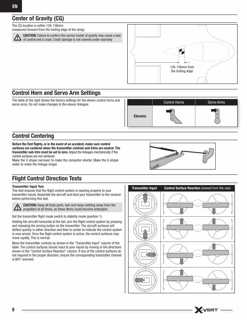
Center of Gravity (CG)126-136mm
(measured forward from the trailing edge of the wing)
Flight Timer Setting4 minutes with the 450mAh fl ight battery8 minutes with the 800mAh fl ight battery Table of Contents
6.4-7.0 oz (182-200 g)
10.4
in (2
64m
m)
19.85 in (504mm)
Specifi cations
Motors: (2) 280 Brushless Outrunner 2600Kv (EFLM1809)
Installed Installed
Servos: (2) 4 g Servos (SPMSA220) Installed Installed
Receiver/ESC: RX/ESC/Flight Controller (EFLAS1810) Installed Installed
Battery:2S 7.4V 450-800mAh LiPo Included Required
Battery Charger: 2-cell Li-Po battery balancing chargerand power supply(EFLUC1009 and EFLC4002 included with RTF only)
Included Required
Transmitter: Full-Range 6 channel 2.4GHz with Spektrum™ DSMX® technology(SPMR1000, Spektrum DXe included with RTF only)
Included Required
Included with the RTF only
Flight Mode (switch pos) SAFE® AS3X®
Multirotor (0) Yes No
Stability (1) Yes No
Acro (2*) No Yes
Prefl ight .............................................................................................................. 4Charging Warnings.............................................................................................. 4Battery Charging ................................................................................................. 4Installing the DXe Transmitter Batteries (RTF) ...................................................... 5DXe Transmitter Control (RTF) ............................................................................. 5BNF Transmitter Setup ....................................................................................... 6Model Assembly ................................................................................................. 6Transmitter and Receiver Binding ........................................................................ 7Battery Installation and ESC Arming .................................................................... 7Center of Gravity (CG) ........................................................................................ 8Control Horn and Servo Arm Settings .................................................................. 8Control Centering ............................................................................................... 8Flight Control Direction Tests ............................................................................... 8Flight Modes ....................................................................................................... 9Understanding the Primary Flight Controls ........................................................ 10Flying Your Aircraft ............................................................................................ 12In Flight Trimming ............................................................................................. 13Post Flight......................................................................................................... 13Motor Service ................................................................................................... 13FPV System Installation (Optional) ..................................................................... 14Troubleshooting Guide ...................................................................................... 16AMA National Model Aircraft Safety Code .......................................................... 17Limited Warranty .............................................................................................. 18Contact Information .......................................................................................... 19FCC Information ............................................................................................... 19IC Information ................................................................................................... 19Compliance Information for the European Union ................................................ 19Decal Placement Options / Aufkleber Optionen /Options de décalcomanie / Opzioni di decalcomanie ......................................... 72Exploded View / Explosionszeichnung / Vue Éclatée / Vista Esplosa ................... 74Replacement Parts / Ersatzteile / Pièces de rechange / Pezzi di ricambio .......... 75Optional Parts / Optionale Bauteile / Pièces optionnelles / Pezzi opzionali .......... 75

EN
4
Prefl ight
1. Remove and inspect contents.
2. Read this instruction manual thoroughly.
3. Charge the fl ight battery.
4. Setup transmitter using transmitter setup chart.
5. Fully assemble the airplane.
6. Install the fl ight battery in the aircraft (once it has been fully charged).
7. Check the Center of Gravity (CG).
8. Bind the aircraft to your transmitter.
9. Make sure linkages move freely.
10. Perform the Control Direction Test with the transmitter.
11. Perform the stability system control direction test with the aircraft.
12. Adjust fl ight controls and transmitter.
13. Perform a radio system range test.
14. Find a safe open area to fl y.
15. Plan fl ight for fl ying fi eld conditions.
NOTICE: Charge only batteries that are cool to the touch and are not damaged. Look at the battery to make sure it is not damaged e.g., swollen, bent, broken or punctured.
1. Connect the AC power supply (A) to the charger.2. Connect the other end of the power supply to an appropriate AC power source.3. Connect the battery balance lead to the charger adapter (B).
WARNING: Only connect the battery balance lead to the charger adapter. Never attempt to connect any other type of lead to the charging adapter or charger port.
4. Connect the charger adapter to the charger (C).5. Press the Start/Stop Button to begin charging.6. Battery charging is complete when the charger LED is solid green.7. Always disconnect the fl ight battery from the charger immediately upon
completion of charging.Charging a fully discharged (not over-discharged) 800mAh battery takesapproximately 60 minutes.
CAUTION: Only use chargers specifi cally designed to charge the included Li-Po battery. Failure to do so could result in fi re, causing injury or property damage.
CAUTION: Never exceed the recommended charge rate.
LED Indications
Flashing Green LED with power connected but without battery: StandbyFlashing Green LED: Battery connectedFlashing Red LED at varying speeds: ChargingSimultaneously Flashing Red and Green LEDs: BalancingSolid Green LED: Full ChargeRapidly Flashing Red and Green LEDs: Error
CAUTION: Once charging is complete, immediately remove the battery.Never leave a battery connected to the charger.
CAUTION: All instructions and warnings must be followed exactly. Mishandling of Li-Po batteries can result in a fi re, personal injury and/or
property damage.
• NEVER LEAVE CHARGING BATTERIES UNATTENDED.• NEVER CHARGE BATTERIES OVERNIGHT.• By handling, charging or using the included Li-Po battery, you assume all risks
associated with lithium batteries.• If at any time the battery begins to balloon or swell, discontinue use immediately.
If charging or discharging, discontinue and disconnect. Continuing to use, charge or discharge a battery that is ballooning or swelling can result in fi re.
• Always store the battery at room temperature in a dry area for best results.• Always transport or temporarily store the battery in a temperature range of
40–120º F (5–49° C).• Do not store battery or model in a car or direct sunlight. If stored in a hot car,
the battery can be damaged or even catch fi re.
• Always charge batteries away from fl ammable materials.• Always inspect the battery before charging.• Always disconnect the battery after charging, and let the charger
cool between charges.• Always constantly monitor the temperature of the battery pack while charging.• ONLY USE A CHARGER SPECIFICALLY DESIGNED TO CHARGE LI-PO BATTERIES.
Failure to charge the battery with a compatible charger may cause a fi re resulting in personal injury and/or property damage.
• Never discharge Li-Po batteries to below 3V per cell under load.• Never cover warning labels with hook and loop strips.• Never charge batteries outside recommended levels.• Never charge damaged batteries.• Never attempt to dismantle or alter the charger.• Never allow minors to charge battery packs.• Never charge batteries in extremely hot or cold places (recommended between
40–120° F or (5–49° C) or place in direct sunlight.
Charging Warnings
Battery Charging
C
A
B

EN
5
Fli ght Mode Switch0 = Multirotor Mode1 = Stability Mode, Forward Flight2 = Acro Mode, Forward Flight*
Bind Switch/Motor Arm/Disarm Switch
Throttle Cut †
A
B
C
D
E
F
G
* The RTF version of the X-VERT is shipped with only Multirotor and Stability fl ight modes active. Flight mode switch positions 1 and 2 both access Stability Mode, indicated by the red LED on the fl ight control board. To access Acro Mode in the RTF version, see the Flight Modes section.
† Activating the throttle cut switch while the motors are armed will immediately disarm the motors. You must return the throttle cut switch to the “arm” (0) position and then use the motor arm/disarm switch to re-arm the motors.
Installing the DXe Transmitter Batteries (RTF)The LED indicator fl ashes and the transmitter beeps progressively faster as the battery voltage drops.
Replace the transmitter batteries when the transmitter begins to beep.
DXe Transmitter Control (RTF)
A B C D E F G
Mode 1Aileron (Left/Right) Throttle (Up/Down)
Throttle Trim
Aileron Trim
ON/OFF Switch
Rudder Trim
Elevator Trim
Rudder (Left/Right) Elevator (Up/Down)
Mode 2Aileron (Left/Right) Elevator (Up/Down)
Elevator Trim
Aileron Trim
ON/OFF Switch
Rudder Trim
Throttle Trim
Rudder (Left/Right) Throttle (Up/Down)
Dual Rate SwitchLED Indicator

EN
6
Model Assembly
Install the Wingtip Plates/Landing GearThe wingtips and tip plates are marked with an “R” and “L”. Match the tip plate to the corresponding wingtip.Slide the tip plates forward over the wingtips until the lock clicks in place.To remove the plates, press the locking tab in and slide the plate to the rear.
BNF Transmitter Setup
The X-VERT™ aircraft requires a transmitter with a minimum of 6 channelswith one 3-position switch and one momentary switch available.Flight Modes are controlled by channel 5 (GEAR).Motor arming/disarming is controlled by channel 6 (AUX 1).
IMPORTANT: After you set up your model, always rebind the transmitter and receiver to set the desired failsafe positions.
Using the settings shown in the table:Sw itch B = Flight Modes
Position 0 = Multirotor ModePosition 1 = Stability ModePosition 2 = Acro Mode
Switch I = Motor Arm/DisarmSwitch H = Throttle Cut
ExpoIf desired, you may add exponential to soften the feel of the controls around neutral. We recommend starting with 10% on the aileron and elevator channels for Acro Mode only. You may adjust the expo values to better suit your fl ying style.
Computerized Transmitter Setup(DXe*, DX6e, DX6, DX7 (Gen2), DX8 (Gen2), DX9, DX18 and DX20)
Start all transmitter programming with a blank ACRO model (perform a model reset), then name the model. Set DR values to Hi 100% Low 70%Set Throttle Cut to Active Switch H
DX6eDX6 (Gen2)DX7 (Gen2)DX8 (Gen2)DX9DX18DX20
1. Go to the SYSTEM SETUP2. Set MODEL TYPE: AIRPLANE 3. Set AICRAFT TYPE: WING: NORMAL4. Set CHANNEL ASSIGN: (NEXT) CHANNEL INPUT CONFIG: GEAR: B AUX1: I
* To download the DXe X-Vert setup, visit www.spektrumrc.com.
Install the Propeller GuardsInstall the propeller guards by sliding them around the propellers and over the motor pods as shown, until they snap into place.Install 2 screws into each guard to secure in place. Do not overtighten the screws as damage to the mounts or guards may result.

EN
7
Binding Procedure
1. Center all trims and move the throttle stick to the lowest position.
2. Power OFF the transmitter.
3. Place the aircraft upright on the wingtip landing gear, on a level surface. Install a fully charged fl ight battery and connect it to the fl ight controller. The fl ight controller will beep once and the green LED will fl ash to indicate the fl ight controller is initializing.
4. When the red LED on the fl ight controller continuously fl ashes, power ON the transmitter in bind mode. Refer to your transmitter’s manual for specifi c binding instructions.To enter bind mode in the RTF included DXe transmitter, press and hold the bind button and then power on the transmitter. The LED indicator will fl ash rapidly to indicate the transmitter is in bind mode. Release the bind button.
5. The receiver is bound to the transmitter when the LED on the receiver glows solid.
IMPORTANT: After binding the receiver and transmitter for the fi rst time, the transmitter must be powered on before the aircraft. Failure to power on the transmitter fi rst will cause the receiver to automatically go into bind mode, requiring the transmitter and receiver to have to be re-bound.
Battery Installation and ESC Arming
Battery SelectionThe RTF version includes a 2S 7.4V 800mAh LiPo battery (EFLB8002SJ30).We recommend a 2S 7.4V 450-800mAh LiPo battery. Refer to the Optional Parts list for other recommended batteries.
Installation1. Lower the throttle and throttle trim to the lowest settings. Power on the
transmitter and wait approximately 5 seconds.2. Open the battery hatch.3. Apply the loop side (soft side) of the hook and loop tape to the bottom of
your battery and the hook side to the battery tray. Use enough hook and loop material to ensure the battery is held securely in place through even the most violent aerobatic maneuvers.
NOTICE: Failure to use adequate hook and loop material may allow the battery to become dislodged or ejected in fl ight. Movement of the battery in fl ight may cause a change of the center of gravity and loss of control.
4. Install the fully charged battery centered in the battery compartment. 5. Connect the battery lead to the aircraft power lead, noting correct polarity.
CAUTION: Connecting the battery to the aircraft power lead with reversed polarity will cause damage to the fl ight controller and the battery. Damage
caused by incorrectly connecting the battery is not covered under warranty.
6. The aircraft must be either vertical on the landing gear or horizontal on its back to initialize. Keep the aircraft immobile and away from wind or the fl ight control system may not initialize.
CAUTION: Always keep hands away from the propeller. When armed, the motor will turn the propeller in response to any throttle movement.
7. Close the battery hatch.8. Refer to the Center of Gravity section to ensure the model balances at the
recommended CG.
The transmitter included with the RTF version of this aircraft is pre-bound to the receiver at the factory. If for any reason it becomes necessary to re-bind the transmitter to the receiver, follow the binding procedure in the table.The BNF version of this product requires an approved Spektrum™ DSM2®/DSMX® compatible transmitter. Visit www.bindnfl y.com for a complete list of approved transmitters. Follow the binding procedure in the table to bind your transmitter to the aicraft receiver.If you encounter problems, follow the binding instructions and refer to the troubleshooting guide for other instructions. If necessary, contact the appropriate Horizon Product Support offi ce.
Transmitter and Receiver Binding
EN
8
Flight Control Direction Tests
Transmitter Input TestThis test ensures that the fl ight control system is reacting properly to your transmitter inputs. Assemble the aircraft and bind your transmitter to the receiver before performing this test.
CAUTION: Keep all body parts, hair and loose clothing away from the propellers at all times, as these items could become entangled.
Set the transmitter fl ight mode switch to stability mode (position 1).
Holding the aircraft horizontal at the tail, arm the fl ight control system by pressing and releasing the arming button on the transmitter. The aircraft surfaces will defl ect quickly in either direction and then to center to indicate the control system is now armed. Once the fl ight control system is active, the control surfaces may move rapidly. This is normal.
Move the transmitter controls as shown in the “Transmitter Input” column of the table. The control surfaces should react to your inputs by moving in the directions shown in the “Control Surface Reaction” column. If any of the control surfaces do not respond in the proper direction, ensure the corresponding transmitter channel is NOT reversed.
Transmitter Input Control Surface Reaction (viewed from the rear)
Before the fi rst fl ights, or in the event of an accident, make sure control surfaces are centered when the transmitter controls and trims are neutral. The transmitter sub-trim must be set to zero. Adjust the linkages mechanically if the control surfaces are not centered.Make the U-shape narrower to make the connector shorter. Make the U-shape wider to make the linkage longer.
Control Centering
Center of Gravity (CG) The CG location is within 126-136mm(measured forward from the trailing edge of the wing).
CAUTION: Failure to confi rm the correct center of gravity may cause a loss of control and a crash. Crash damage is not covered under warranty.
126-136mm fromthe trailing edge
Control Horn and Servo Arm SettingsThe table at the right shows the factory settings for the elevon control horns andservo arms. Do not make changes to the elevon linkages. Control Horns Servo Arms
Elevons

EN
9
Stability System Reaction TestThis test ensures that the fl ight control system is reacting properly to external forces, such as wind. Assemble the aircraft and bind your transmitter to the receiver before performing this test.
CAUTION: Keep all body parts, hair and loose clothing away from the propellers at all times, as these items could become entangled.
Set the transmitter fl ight mode switch to stability mode (position 1).
Holding the aircraft horizontal at the tail, arm the fl ight control system by pressing and releasing the arming button on the transmitter. The aircraft surfaces will defl ect quickly in either direction and then to center to indicate the control system is now armed. Once the fl ight control system is active, the control surfaces may move rapidly. This is normal.
Pivot the entire aircraft as shown in the “Aircraft Movement” column of the table. The control surfaces should react to your movements by moving in the directions shown in the “Control Surface Reaction” column. If the control surfaces do not respond as shown, do not fl y the aircraft. Contact Horizon Product Support.
Aircraft Movement Control Surface Reaction (viewed from the rear)
Multirotor Mode (switch position 0)Vertical mode allows the aircraft to take off and land vertically.The fl ight controls work similar to a quadcopter.• Receiver LED green• Limited bank and pitch angle• Self levelling when the controls are centered
Stability Mode (switch position 1*)Stability mode allows the novice pilot to get comfortable fl yinga fi xed wing aircraft in forward fl ight.• Receiver LED red• Limited bank and pitch angle• Self levelling when the controls are centered
Acro Mode (switch position 2*)Acro mode is intended for experienced pilots who are comfortable fl ying the aircraft in any orientation.• Receiver LED green and red• No bank angle limits• No self levelling when the controls are centered• Fully aerobatic capable
* The RTF version is shipped with only multirotor and stability fl ight modes active. Flight mode switch positions 1 and 2 both access stability mode, indicated by the red LED on the fl ight control board. You must unlock acro mode using the included DXe transmitter.
Accessing Acro Mode in the RTF X-VERT
CAUTION: Acro mode is intended only for experienced pilots who have mastered fi xed wing aerobatic fl ight. Attempting to use acro mode
without the necessary fl ight experience may cause loss of control, property damage or a crash. Crash damage is not covered under warranty.
To access acro mode:1. Power on the transmitter2. Power on the aircraft, allowing it to initialize fully.3. Hold the transmitter sticks to the
bottom, inside corners and quickly cycle the fl ight mode switch from position 0 to position 2 and back 3 times.The control surfaces will cycle multiple times. If successful, the LED on the fl ight control board will show both green and red LEDs when the fl ight mode switch is set to acro mode (position 2).
Once accessed, acro mode will be available whenever the aircraft is powered on. It is not necessary to unlock the mode every time the aircraft is powered on.If you wish to lock acro mode again, repeat the directions above until the receiver LED shows stability mode (red LED) in both fl ight mode switch position 1 and 2.
Flight Modes

EN
10
Understanding the Primary Flight Controls
The X-VERT aircraft is capable of both vertical, multirotor-style fl ight and forward, airplane-style fl ight. It is important to understand how the primary fl ight controls function and how the aircraft reacts in both fl ight modes. Take a few minutes to familiarize yourself with the controls prior to attempting your fi rst fl ight.
Multirotor Flight Mode
Top view
ClimbDescend
Yaw right Yaw left
Throttle
Elevator
Aileron
Throttle up
Elevator down
Aileron right
Throttle down
Elevator up
Aileron left
Left side view
Top view
Left side view
Top view
BackwardForward
Right Left
Top view
Rudder
Rudder right Rudder left
Top view Top view

EN
11
Stability and Acro Forward Flight Modes
Roll leftRoll right
Faster Slower
Pitch down Pitch up
Yaw right Yaw left
Throttle
Elevator
Aileron
Rudder
Throttle up
Elevator down
Aileron right
Rudder right
Throttle down
Elevator up
Aileron left
Rudder left
Left side view
Rear view
Top view
Left side view
Top view
Rear view
Left side view Left side view

EN
12
Flying Your Aircraft
Consult local laws and ordinances before choosing a fl ying location.
NOTICE: While the aircraft is capable of forward fl ight in light to moderate winds, we recommend using multirotor mode only in very light wind or calm conditions. Using multirotor mode or transitioning from forward fl ight to multirotor mode in windy conditions will cause the aircraft to be blown downwind and could cause a loss of control or a crash. Use only the forward fl ight modes for fl ying in windy conditions.
Range Check your Radio SystemBefore you fl y, range check the radio system. Refer to your specifi c transmitter instruction manual for range test information.
Just Before FlightThe recommended battery is the EFLB8002SJ30 800mAh LiPo. For best results, always use a fresh battery. Due to the increased battery draw of this or any vertical lift aircraft, using an old or worn battery will give far shorter fl ight times.For your fi rst fl ights with the recommended 800mAh battery pack, set your transmitter timer or a stopwatch to 8 minutes.
NOTICE: Never fl y the aircraft without fi rst setting and activating a timer.
After 8 minutes, land the aircraft. Adjust your timer for longer or shorter fl ights depending on your preference and battery usage.
ArmingThe X-VERT can be armed in any of the three fl ight modes. The active fl ight mode during arming determines how the aircraft will indicate it is armed and ready for fl ight.Prior to arming, lower the throttle to the lowest setting. The aircraft will not arm unless the throttle is fully lowered.When the aircraft is armed in multirotor mode, the motors will spin up to idle speed.When the aircraft is armed in either stability or acro mode, the elevons will cycle and then return to center. The motors will not run until throttle is applied.IMPORTANT: As a safety feature, arming in one fl ight mode and changing to another fl ight mode prior to adding throttle will cause the aircraft to disarm.
Vertical Takeoff1. Place the aircraft vertically on the landing gear on a fl at, level surface with the
top facing you. The aircraft must be sitting vertically to arm in multirotor mode.2. Set the fl ight mode to multirotor fl ight.3. Lower the throttle to the lowest setting. The aircraft will not arm unless the
throttle is fully lowered.4. Arm the aircraft by pressing and holding the motor arm/disarm switch. When
the aircraft is armed in multirotor mode the motors will spin up to idle speed.5. Gradually increase the throttle until the model lifts off and is approximately
2 ft. (600mm) off the ground. Avoid forcing the aircraft into the air.
Hovering and Vertical FlightMaking small corrections on the transmitter, try to hold the aircraft in one spot. If fl ying in calm winds, the model should require almost no corrective inputs. After moving the aileron/elevator stick and returning it to center the model should level itself. The model may continue to move due to inertia. Move the stick in the opposite direction to stop the movement.After you become comfortable hovering, you can progress into fl ying the model to different locations, keeping the top pointed towards you at all times to aid with orientation. You can also ascend and descend using the throttle stick.When comfortable with these maneuvers, attempt fl ying with the aircraft in different orientations. It is important to keep in mind that the fl ight control inputs will rotate with the aircraft, so always try to picture the control inputs relative to the nose of the aircraft. For example, pushing the elevator stick forward will always pitch the nose toward the bottom of the fuselage, causing the aircraft to move forward and vice versa.Hovering and multirotor fl ight is best attempted in low wind conditions. Attempting to fl y in higher winds will cause the aircraft to drift downwind dramatically if the top or bottom are turned into the wind. It is possible to hold position somewhat if the aircraft is turned sideways into the wind, but this is recommended only for more experienced pilots.Lowering the throttle to descend while fl ying in multirotor mode in choppy or windy conditions may cause the aircraft to appear “bouncy” or erratic. This is normal as the fl ight controller reacts to compensate for the moving air.
Transitioning In FlightTo transition to stability, forward fl ight from multirotor fl ight, change the fl ight mode switch on your transmitter to the stability fl ight mode position. The throttle will increase slightly and the aircraft will pitch forward until forward fl ight attitude has been achieved. It is normal to have some slight oscillations in pitch as the aircraft transitions into forward fl ight. While in stability fl ight mode the motors use differential thrust to provide yaw control.
NOTICE: Always fl y in a clear and open area. While the transition from multirotor to forward fl ight does not require much space, you will not be able to change the direction of fl ight until the transition is complete. NEVER attempt to transition to forward fl ight indoors in anything but a large open space such as a large gymnasium.
To transition to multirotor fl ight from forward fl ight, reduce the airspeed and change the fl ight mode switch on your transmitter to the multirotor fl ight position. The throttle will increase slightly and the aircraft will pitch up until it reaches a multirotor attitude.
NOTICE: If you are fl ying in wind, the aircraft will be blown downwind after it transitions to vertical mode.
Transition to vertical fl ight at low throttle will cause the aircraft to descend until more throttle is applied.
Stability and Acro Forward FlightFly the aircraft and trim it for level fl ight per the In Flight Trimming section.The X-VERT fl ies in a very similar manner in forward fl ight to any other fi xed-wing aircraft. It is capable of a wide range of aerobatic maneuvers, including loops and rolls. Additionally, the differential thrust of the motors allows for unique spinning and tumbling maneuvers.
Hand LaunchingHand launching is preferred when fl ying in higher winds or when vertical takeoff may not be possible.1. Lower the throttle to the lowest setting. The aircraft will not arm unless the
throttle is fully lowered.2. Power on the model normally, allowing it to initialize completely.3. Set the fl ight mode switch to stability mode.4. Hold the aircraft horizontal, with a fi rm grip at the rear-center of the airframe,
being careful not to interfere with the control surfaces.5. Arm the aircraft by pressing and holding the motor arm/disarm switch. When the
aircraft is armed in either stability or acro mode, the control surfaces will cycle left and right and then return to center. The aircraft is now armed in stability mode. The motors are armed and will run with any throttle input.
6. Increase the throttle to approximately 50–75%.7. Give the aircraft a light, underhand toss into the wind.
Landing The preferred method of landing is to transition the aircraft into multirotor fl ight mode and bring it into a low hover. Slowly lower the throttle to descend to a soft landing. Immediately activate throttle cut or press and hold the motor arm/disarm switch to stop the motors when the aircraft touches down. Failure to stop the motors may cause the aircraft to skip or hop across the ground if the fl ight controller does not recognize the aircraft has landed.It is possible to land the aircraft in forward fl ight as well when conditions dictate it, such as in high wind. To land while in a forward fl ight mode, turn the aircraft into the wind and lower the throttle to decrease the forward speed. Fly the aircraft to approximately 6 inches (15cm) or less above the runway, using a small amount of throttle for the entire descent. Keep the throttle on until the aircraft is ready to touch down. Just before touch down, keep the wings level and the airplane pointed into the wind. Gently lower the throttle while easing back on the elevator to bring the aircraft to touch down on the runway as slowly and gently as possible. Using stability mode for landings will help stabilize the aircraft.IMPORTANT: The aircraft will automatically disarm after sitting for approximately 3 seconds with no throttle, no control inputs or aircraft movement.The average fl ight time with a mixture of multirotor and forward fl ight using the recommended 800mAh fl ight battery is approximately 8 minutes.

EN
13
After landing disconnect and remove the Li-Po battery from the aircraft to prevent trickle discharge. Charge your Li-Po battery to about half capacity before storage. During storage, make sure the battery charge does not fall below 3V per cell.
NOTICE: If a crash is imminent, activate the throttle cut to immediately stop the motors to reduce the possibility of damage to the airframe and electronic components.
NOTICE: Crash damage is not covered under warranty.
NOTICE: Never leave the aircraft in direct sunlight or in a hot, enclosed area such as a car. Doing so can damage the aircraft.
Propeller InspectionInspect the propellers after every fl ight. Check for breaks, cracks or bends of the propeller tips. Even minor damage may affect the fl ight performance of the aircraft and may cause unwanted yaw under throttle in forward fl ight. If any damage is found, replace the propeller before attempting additional fl ights.
Low Voltage Cutoff (LVC)When a Li-Po battery is discharged below 3V per cell, it will not hold a charge. The aircraft’s ESC protects the fl ight battery from over-discharge using Low Voltage Cutoff (LVC). Once the battery discharges to approzimately 3.45V per cell, the LVC will reduce the power to the motor in order to leave adequate power to the receiver and servos to land the aircraft.
How the LVC function is indicated is dependent on which fl ight mode is active.While in vertical mode, the motor power will decrease. The aircraft will respond sluggishly to throttle and will gradually not be able to gain or hold altitude. When the motor power decreases, land the aircraft immediately and replace or recharge the fl ight battery.While in either of the forward fl ight modes, the motors will cut off briefl y and power back on. If the motors cut off or surge in power, land immediately and replace or recharge the fl ight battery. Transition back to vertical mode is possible if done early in the LVC
NOTICE: Repeated fl ying to LVC may damage the fl ight battery.
LVC does not prevent the battery from over-discharge during storage.Tip: Monitor your aircraft battery’s voltage before and after fl ying by using aLi-Po Cell Voltage Checker (EFLA111, sold separately).
Repairs Thanks to the Z-Foam™ material in this aircraft, most repairs to the foam can be made using virtually any adhesive (hot glue, regular CA, epoxy, etc). When parts are not repairable, refer to the parts list at the end of this manual for a listing of all replacement and optional parts for ordering by item number.
Post Flight
1. Disconnect the fl ight battery from the fl ight controller2. Power OFF the transmitter.3. Remove the fl ight battery from the aircraft.4. Recharge the fl ight battery.
5. Repair or replace all damaged parts.6. Store the fl ight battery apart from the aircraft and monitor the battery charge.7. Make note of the fl ight conditions and fl ight plan results, planning for
future fl ights.
Familiarize yourself with the Flying Your Aircraft section prior to trimming your aircraft. Trimming should be done in calm wind conditions and with a fully charged transmitter and fl ight battery. Trimming should only be necessary in acro mode, as the fl ight controller will compensate for minor trim issues in multirotor and stability modes. It is important to make any trim adjustments mechanically in the control linkages and re-set the transmitter trims to center to keep any changes made from affecting multirotor and stability modes.
1. Power on and takeoff normally. 2. Change the fl ight mode to acro and fl y straight and level at approximately
3/4 throttle. 3. Trim the aircraft for level fl ight using the trim buttons on the transmitter.4. When the aircraft maintains reasonable straight and level fl ight, land the aircraft.
5. Set the fl ight mode back to acro mode if it was changed for landing. Power cycle the aircraft. Do not activate the throttle. Take note of the neutral postion of the control surfaces.
6. Adjust the control linkages mechanically, as shown in the “Control Centering” section, to compensate for the amount of trim entered.
7. Re-center the trims on the transmitter. The transmitter trims should always be centered for best fl ight performance.
8. Fly the aircraft again to check the changes made.9. Repeat the trimming process until the aircraft will maintain reasonable
straight and level forward fl ight without excessive control corrections.When the initial trimming process is done, the aircraft should not require large amounts of trimming on subsequent fl ights. If large amounts of trim are needed to hold straight and level on later fl ights, land the aircraft and check the control surfaces for damage or binding.
In Flight Trimming
CAUTION: Always disconnect the fl ight battery before performing motor service.
Motor Removal1. Disconnect the motor lead from the fl ight control board.2. Remove the propeller retention screw and propeller from the motor shaft.3. Looking through the hole in the bottom of the motor nacelle, remove the
setscrew from the motor mount.4. Very carefully remove the tape covering the motor wire lead.5. Pull the motor from the motor mount, feeding the motor wire lead through the
nacelle.
Assemble in reverse order.
Note: The illustration shows the propeller guard removed for clarity.It is not necessary to remove the guards to replace the motors.
Motor Service
Motor wire lead cover tape

EN
14
b
FPV System Installation (Optional)
If you are operating this product in North America, you are required to have an Amateur Radio (HAM) license. Visit www.arrl.org for more information.
Consult local laws and ordinances before operating FPV equipment. In some areas, FPV operation may be limited or prohibited. You are responsible for operating this product in a legal and responsible manner.
Items required for FPV installation and operation:
• FPV Camera Mount with Servo (EFL1812)• FPV Camera (SPMVCM01)• 150mW Video Transmitter (SPMVTM150) North America only• 25mW Video Transmitter (SPMVTM025) European Union only• Spektrum™ 4.3 inch Video Monitor with Headset (SPMVM430C) or suitable
headset or ground station
Installing the Optional FPV System
1. Remove the fl ight battery from the aircraft.2. Install the camera to the camera mount with double sided tape. The camera
should be installed so the wiring harness is at the top left side of the mount as shown (a).
3. Peel the backing from the double stick tape of the FPV mount.4. Attach the mount to the nose of the aircraft as shown (b), making sure the
mount is centered and level to the aircraft. 5. Connect the 4 pin/ 3-wire connector of the y-harness to the open terminal (c)
on the fl ight control board.6. Connect the 2-wire power connector of the y-harness to the video transmitter
power lead (d).7. Connect the 3-wire extension to the terminal on the video transmitter (e).8. Apply double-sided tape to the bottom of the video transmitter and slide it under
the fl ight control board as shown (f). It should slide in far enough that about half of the transmitter is under the fl ight control board and the channel button and LEDs are still visible. Do not force the transmitter any farther.
9. Determine whether you wish to route the wire leads internally or externally around the fuselage and into the battery hatch.If routing the wires internally, carefully drill a hole through the fuselage as shown (g), large enough to accomodate the servo and camera connectors, from the nose of the aircraft into the battery compartment.
10. Route the servo end of the y-harness and the camera extension from the battery compartment to the FPV mount.
11. Connect the servo lead to the y-harness connector.12. Connect the camera lead to the 3-wire extension. Leave enough slack in the
wire extension at the nose so the camera mount can pivot through its full range of travel without binding.
Flight Control Board
Open terminal
c
fChannel buttonLEDs
e
g
a
d

EN
15
Operating the FPV MountThe FPV camera mount does not require any programming or additional channels in the transmitter. All functions are controlled by the fl ight control board on the aircraft. Changing between the fl ight modes with the fl ight mode switch moves the camera to one of two preset positions.• While in multirotor mode the camera faces toward the bottom of the aircraft.
This allows for a forward view while fl ying in multirotor mode.• While in either of the forward fl ight modes, stability or acro, the camera faces
toward the front of the aircraft.The angle of the camera can be adjusted slightly for your preferred optimal viewing angle by adjusting the length of the control rod on the camera mount. Refer to the Control Centering section for a description of how to adjust the length of the control rod. Ensure any adjustments made to the camera control rod do not cause binding in either the multirotor or forward fl ight mode camera positions.
NOTICE: Never try to move the mount up or down by hand. Damage to the mount servo may result.
Operating the Video Transmitter
Consult local laws and ordinances before operating FPV equipment. In some areas, FPV operation may be limited or prohibited. You are responsible for operating this product in a legal and responsible manner. See the Available Frequency table to fi nd the desired video channel and band. The video transmitter channel and band are changed using the button on the video transmitter, as shown. There are 6 LEDs on the video transmitter board. The red LED is the channel indicator. The next 5 blue LEDs are the band indicators.
Channel Selection:1. Channel 1 is indicated by the red LED glowing solid.2. Press the button to cycle through the channels (1-8). The red LED will fl ash
once as you cycle through each channel. Press the button once for eachchannel until the desired channel is reached. If unsure of the currenttransmitter channel, press the button to cycle the channels until you reach channel 1, indicated by a solid red LED, then cycle to the channel desired.
Band Selection:1. Press and hold the button to change the video transmitter band.2. Each time the button is pressed and held, the blue band LED will indicate a
change to the next available band. The blue LEDs indicate FS/IRC band, band E (North America only), band A, race band and band B, as shown in the illustration.
NOTICE: Due to the additional current draw of the camera, servo and video transmitter on the aircraft electrical system, using the optional FPV system will shorten the expected fl ight times.
Band CH 1 CH 2 CH 3 CH 4 CH 5 CH 6 CH 7 CH 8
Band A 5865 5845 5825 5805 5785 5765 5745 5725Band B 5733 5752 5771 5790 5809 5828 5847 5866Band E 5705 5685 5665 5665 5885 5905 5905 5905FS/IRC 5740 5760 5780 5800 5820 5840 5860 5880RaceBand 5658 5695 5732 5769 5806 5843 5880 5917
Band CH 1 CH 2 CH 3 CH 4 CH 5 CH 6 CH 7 CH 8
Band A 5865 5845 5825 5805 5785 5765 5745 5745
Band B 5733 5752 5771 5790 5809 5828 5847 5866
FS/IRC 5740 5760 5780 5800 5820 5840 5860 5860
RaceBand 5732 5732 5732 5769 5806 5843 5843 5843
Video Transmitter LEDs
150mWNorth American
version
25mWEU
version
Band
Channel
Available Frequencies, North America (mHz)
Available Frequencies, European Union (mHz)
Channel buttonLEDs

EN
16
Problem Possible Cause Solution
Aircraft will not arm Throttle cut switch in the disarm position (position 1) Set the throttle cut switch to the arm position (position 0)
Aircraft will not re-spond to throttle but responds to other controls
Throttle not at idle and/or throttle trim too high Reset controls with throttle stick and throttle trim at lowest setting
Throttle servo travel is lower than 100% Make sure throttle servo travel is 100% or greater
Throttle channel is reversed Reverse throttle channel on transmitter
Motors disconnected from ESCs Make sure motors are connected to the ESCs
Extra propeller noise or extra vibration
Damaged propeller and spinner, collet or motor Replace damaged parts
Propeller is out of balance Balance or replace propeller
Prop bolt is loose Tighten the prop bolt
Reduced fl ight time or aircraft underpow-ered
Flight battery charge is low Completely recharge fl ight battery
Flight battery damaged or old Replace fl ight battery with a fresh battery and follow fl ight battery instructions
Flight conditions too cold Make sure battery is warm before use
Battery capacity too low for fl ight conditions Replace battery or use a larger capacity battery
Aircraft will not Bind (during binding) to transmitter
Transmitter too near aircraft during binding processMove powered transmitter a few feet from aircraft, disconnect and reconnect fl ight battery to aircraft
Aircraft or transmitter is too close to large metal object, wireless source or another transmitter
Move aircraft and transmitter to another location and attempt binding again
Flight battery/transmitter battery charge is too low Replace/recharge batteries
Bind switch or button not held long enough during bind process
Power off transmitter and repeat bind process. Hold transmitter bind button or switch until receiver is bound
Aircraft will not connect (after binding) to transmitter
Transmitter too near aircraft during connecting processMove powered transmitter a few feet from aircraft, disconnect and reconnect fl ight battery to aircraft
Aircraft or transmitter is too close to large metal object, wireless source or another transmitter
Move aircraft and transmitter to another location and attempt connecting again
Aircraft bound to different model memory(ModelMatch™ radios only)
Select correct model memory on transmitter
Flight battery/Transmitter battery charge is too low Replace/recharge batteries
Transmitter may have been bound to a different aircraft using different DSM protocol
Bind aircraft to transmitter
Control surface does not move
Control surface, control horn, linkage or servo damage Replace or repair damaged parts and adjust controls
Servo wire damaged or connections loose Do a check of wires and connections, connect or replace as needed
Transmitter is not bound correctly or the incorrectaircraft was selected
Re-bind or select correct airplanes in transmitter
Flight battery charge is low Fully recharge fl ight battery
Flight controller is damaged Replace the fl ight controller
Controls reversed Transmitter settings are reversed Perform the Control Direction Test and adjust the controls on transmitter appropriately
Oscillation
Damaged propeller Replace propeller
Imbalanced propeller Balance the propeller
Motor vibration Replace parts or correctly align all parts and tighten fasteners as needed
Loose battery Use more hook and loop material to secure the battery
Loose fl ight controller Align and secure the fl ight controller in fuselage
Loose aircraft controls Tighten or otherwise secure parts (servo, arm, linkage, horn and control surface)
Worn parts Replace worn parts (especially propeller or servo)
Irregular servo movement Replace servo
Inconsistent fl ight performance
Trim is not at neutral If you adjust trim more than 8 clicks, adjust the clevis to remove trim
Sub-Trim is not at neutral Remove all sub-trim. Adjust the servo linkage for proper alignment of surfaces
Aircraft was not kept upright and immobile for 5 seconds after battery connection
With the throttle stick in lowest position, disconnect battery, then reconnect batteryand keep the aircraft still for 5 seconds
Aircraft motor surges while in forward flight modes
Low battery. Low Voltage Cutoff is being triggered. Recharge fl ight battery or replace battery that is no longer performing
Aircraft does not maintain or gainaltitude in vertical flight mode
Low battery. Low Voltage Cutoff is being triggered. Recharge fl ight battery or replace battery that is no longer performing
Aircraft immediately flips or crashes on throttle up
Propellers installed incorrectlyInstall the propellers with the “R” propeller on the right side motorand the “L” propeller on the left side motor
Aircraft is unstable in yaw or yaws to one side under throttle in forward flight
Damaged propeller Inspect the propellers and replace any damaged parts
Troubleshooting Guide

EN
17
Effective January 1, 2014
A. GENERAL
A model aircraft is a non-human-carrying aircraft capable of sustained fl ight in the atmosphere. It may not exceed limitations of this code and is intended exclusively for sport, recreation, education and/or competition. All model fl ights must be conducted in accordance with this safety code and any additional rules specifi c to the fl ying site.
1. Model aircraft will not be fl own:(a) In a careless or reckless manner.(b) At a location where model aircraft activities are prohibited.
2. M odel aircraft pilots will:(a) Yield the right of way to all man carrying aircraft.(b) See and avoid all aircraft and a spotter must be used when appropriate.
(AMA Document #540-D.)(c) Not fl y higher than approximately 400 feet above ground level within three
(3) miles of an airport, without notifying the airport operator.(d) Not interfere with operations and traffi c patterns at any airport, heliport or
seaplane base except where there is a mixed use agreement.(e) Not exceed a takeoff weight, including fuel, of 55 pounds unless in
compliance with the AMA Large Model Aircraft program. (AMA Document 520-A.)
(f) Ensure the aircraft is identifi ed with the name and address or AMA number of the owner on the inside or affi xed to the outside of the model aircraft. (This does not apply to model aircraft fl own indoors).
(g) Not operate aircraft with metal-blade propellers or with gaseous boosts except for helicopters operated under the provisions of AMA Document #555.
(h) Not operate model aircraft while under the infl uence of alcohol or while using any drug which could adversely affect the pilot’s ability to safely control the model.
(i) Not operate model aircraft carrying pyrotechnic devices which explode or burn, or any device which propels a projectile or drops any object that creates a hazard to persons or property.
Exceptions:• Free Flight fuses or devices that burn producing smoke and are securely
attached to the model aircraft during fl ight.• Rocket motors (using solid propellant) up to a G-series size may be used
provided they remain attached to the model during fl ight. Model rockets may be fl own in accordance with the National Model Rocketry Safety Code but may not be launched from model aircraft.
• Offi cially designated AMA Air Show Teams (AST) are authorized to use devices and practices as defi ned within the Team AMA Program Document (AMA Document #718).
(j) Not operate a turbine-powered aircraft, unless in compliance with the AMA turbine regulations. (AMA Document #510-A).
3. Model aircraft will not be fl own in AMA sanctioned events, air shows or model demonstrations unless:(a) The aircraft, control system and pilot skills have successfully demonstrated
all maneuvers intended or anticipated prior to the specifi c event.(b) An inexperienced pilot is assisted by an experienced pilot.
4. When and where required by rule, helmets must be properly worn and fastened. They must be OSHA, DOT, ANSI, SNELL or NOCSAE approved or comply with comparable standards.
B. RADIO CONTROL
1. All pilots shall avoid fl ying directly over unprotected people, vessels, vehicles or structures and shall avoid endangerment of life and property of others.
2. A successful radio equipment ground-range check in accordance with manufacturer’s recommendations will be completed before the fi rst fl ight of a new or repaired model aircraft.
3. At all fl ying sites a safety line(s) must be established in front of which all fl ying takes place (AMA Document #706.)(a) Only personnel associated with fl ying the model aircraft are allowed at or
in front of the safety line.(b) At air shows or demonstrations, a straight safety line must be established.(c) An area away from the safety line must be maintained for spectators.(d) Intentional fl ying behind the safety line is prohibited.
4. RC model aircraft must use the radio-control frequencies currently allowed by the Federal Communications Commission (FCC). Only individuals properly licensed by the FCC are authorized to operate equipment on Amateur Band frequencies.
5. RC model aircraft will not operate within three (3) miles of any pre-existing fl ying site without a frequency-management agreement (AMA Documents #922 and #923.)
6. With the exception of events fl own under offi cial AMA Competition Regulations, excluding takeoff and landing, no powered model may be fl own outdoors closer than 25 feet to any individual, except for the pilot and the pilot’s helper(s) located at the fl ight line.
7. Under no circumstances may a pilot or other person touch a model aircraft in fl ight while it is still under power, except to divert it from striking an individual.
8. RC night fl ying requires a lighting system providing the pilot with a clear view of the model’s attitude and orientation at all times. Hand-held illumination systems are inadequate for night fl ying operations.
9. The pilot of a RC model aircraft shall:(a) Maintain control during the entire fl ight, maintaining visual contact without
enhancement other than by corrective lenses prescribed for the pilot.(b) Fly using the assistance of a camera or First-Person View (FPV) only in
accordance with the procedures outlined in AMA Document #550.(c) Fly using the assistance of autopilot or stabilization system only in
accordance with the procedures outlined in AMA Document #560.
Please see your local or regional modeling association’s guidelines for proper, safe operation of your model aircraft.
AMA National Model Aircraft Safety Code
EN
18
Limited Warranty
What this Warranty CoversHorizon Hobby, LLC, (Horizon) warrants to the original purchaser that the product purchased (the “Product”) will be free from defects in materials and workmanship at the date of purchase.
What is Not CoveredThis warranty is not transferable and does not cover (i) cosmetic damage, (ii) damage due to acts of God, accident, misuse, abuse, negligence, commercial use, or due to improper use, installation, operation or maintenance, (iii) modifi cation of or to any part of the Product, (iv) attempted service by anyone other than a Horizon Hobby authorized service center, (v) Product not purchased from an authorized Horizon dealer, or (vi) Product not compliant with applicable technical regulations, or (vii) use that violates any applicable laws, rules, or regulations.
OTHER THAN THE EXPRESS WARRANTY ABOVE, HORIZON MAKES NO OTHER WARRANTY OR REPRESENTATION, AND HEREBY DISCLAIMS ANY AND ALL IMPLIED WARRANTIES, INCLUDING, WITHOUT LIMITATION, THE IMPLIED WARRANTIES OF NON-INFRINGEMENT, MERCHANTABILITY AND FITNESS FOR A PARTICULAR PURPOSE. THE PURCHASER ACKNOWLEDGES THAT THEY ALONE HAVE DETERMINED THAT THE PRODUCT WILL SUITABLY MEET THE REQUIREMENTS OF THE PURCHASER’S INTENDED USE.
Purchaser’s RemedyHorizon’s sole obligation and purchaser’s sole and exclusive remedy shall be that Horizon will, at its option, either (i) service, or (ii) replace, any Product determined by Horizon to be defective. Horizon reserves the right to inspect any and all Product(s) involved in a warranty claim. Service or replacement decisions are at the sole discretion of Horizon. Proof of purchase is required for all warranty claims. SERVICE OR REPLACEMENT AS PROVIDED UNDER THIS WARRANTY IS THE PURCHASER’S SOLE AND EXCLUSIVE REMEDY.
Limitation of LiabilityHORIZON SHALL NOT BE LIABLE FOR SPECIAL, INDIRECT, INCIDENTAL OR CONSEQUENTIAL DAMAGES, LOSS OF PROFITS OR PRODUCTION OR COMMERCIAL LOSS IN ANY WAY, REGARDLESS OF WHETHER SUCH CLAIM IS BASED IN CONTRACT, WARRANTY, TORT, NEGLIGENCE, STRICT LIABILITY OR ANY OTHER THEORY OF LIABILITY, EVEN IF HORIZON HAS BEEN ADVISED OF THE POSSIBILITY OF SUCH DAMAGES. Further, in no event shall the liability of Horizon exceed the individual price of the Product on which liability is asserted. As Horizon has no control over use, setup, fi nal assembly, modifi cation or misuse, no liability shall be assumed nor accepted for any resulting damage or injury. By the act of use, setup or assembly, the user accepts all resulting liability. If you as the purchaser or user are not prepared to accept the liability associated with the use of the Product, purchaser is advised to return the Product immediately in new and unused condition to the place of purchase.
LawThese terms are governed by Illinois law (without regard to confl ict of law principals). This warranty gives you specifi c legal rights, and you may also have other rights which vary from state to state. Horizon reserves the right to change or modify this warranty at any time without notice.
WARRANTY SERVICES
Questions, Assistance, and ServicesYour local hobby store and/or place of purchase cannot provide warranty support or service. Once assembly, setup or use of the Product has been started, you must contact your local distributor or Horizon directly. This will enable Horizon to better answer your questions and service you in the event that you may need any assistance. For questions or assistance, please visit our website at www.horizonhobby.com, submit a Product Support Inquiry, or call the toll free telephone number referenced in the Warranty and Service Contact Information section to speak with a Product Support representative.
Inspection or ServicesIf this Product needs to be inspected or serviced and is compliant in the country you live and use the Product in, please use the Horizon Online Service Request submission process found on our website or call Horizon to obtain a Return Merchandise Authorization (RMA) number. Pack the Product securely using a shipping carton. Please note that original boxes may be included, but are not designed to withstand the rigors of shipping without additional protection. Ship via a carrier that provides tracking and insurance for lost or damaged parcels, as Horizon is not responsible for merchandise until it arrives and is accepted at our facility. An Online Service Request is available at http://www.horizonhobby.com/content/service-center_render-service-center. If you do not have internet access, please contact Horizon Product Support to obtain a RMA number along with instructions for submitting your product for service. When calling Horizon, you will be asked to provide your complete name, street address, email address and phone number where you can be reached during business hours. When sending product into Horizon, please include your RMA number, a list of the included items, and a brief summary of the problem. A copy of your original sales receipt must be included for warranty consideration. Be sure your name, address, and RMA number are clearly written on the outside of the shipping carton.
NOTICE: Do not ship LiPo batteries to Horizon. If you have any issue with a LiPo battery, please contact the appropriate Horizon Product Support offi ce.
Warranty Requirements For Warranty consideration, you must include your original sales receipt verifying the proof-of-purchase date. Provided warranty conditions have been met, your Product will be serviced or replaced free of charge. Service or replacement decisions are at the sole discretion of Horizon.
Non-Warranty Service
Should your service not be covered by warranty, service will be completed and payment will be required without notifi cation or estimate of the expense unless the expense exceeds 50% of the retail purchase cost. By submitting the item for service you are agreeing to payment of the service without notifi cation. Service estimates are available upon request. You must include this request with your item submitted for service. Non-warranty service estimates will be billed a minimum of ½ hour of labor. In addition you will be billed for return freight. Horizon accepts money orders and cashier’s checks, as well as Visa, MasterCard, American Express, and Discover cards. By submitting any item to Horizon for service, you are agreeing to Horizon’s Terms and Conditions found on our website http://www.horizonhobby.com/content/service-center_render-service-center.
ATTENTION: Horizon service is limited to Product compliant in the country of use and ownership. If received, a non-compliant Product will not be serviced. Further, the sender will be responsible for arranging return shipment of the un-serviced Product, through a carrier of the sender’s choice and at the sender’s expense. Horizon will hold non-compliant Product for a period of 60 days from notifi cation, after which it will be discarded. 10/15

EN
19
Contact Information
FCC ID: BRWEFLAS1810BRWDXE (included in EFL1800 only )
This equipment has been tested and found to comply with the limits for a Class B digital device, pursuant to part 15 of the FCC Rules. These limits are designed to provide reasonable protection against harmful interference in a residential instal-lation. This equipment generates, uses and can radiate radio frequency energy and, if not installed and used in accordance with the instructions, may cause harmful interference to radio communications.However, there is no guarantee that interference will not occur in a particular in-stallation. If this equipment does cause harmful interference to radio or television reception, which can be determined by turning the equipment off and on, the user is encouraged to try to correct the interference by one or more of the following measures:• Reorient or relocate the receiving antenna.• Increase the separation between the equipment and receiver.• Connect the equipment to an outlet on a circuit different from that to which the
receiver is connected.
This device complies with part 15 of the FCC rules. Operation is subject to the following two conditions:(1) This device may not cause harmful interference, and(2) this device must accept any interference received, including interference that may cause undesired operation.
NOTICE: Modifi cations to this product will void the user’s authority to operate this equipment.
This product contains a radio transmitter with wireless technology which has been tested and found to be compliant with the applicable regulations governing a radio transmitter in the 2.400GHz to 2.4835GHz frequency range.
Compliance Information for the European Union
FCC Information
IC InformationIC: 6157A-EFLAS1810
6157A-DXE (included in EFL1800 only )This device complies with Industry Canada licence-exempt RSS standard(s). Operation is subject to the following two conditions: (1) this device may not cause interference, and (2) this device must accept any interference, including interference that may cause undesired operation of the device.
Instructions for disposal of WEEE by users in the European UnionThis product must not be disposed of with other waste. Instead, it is the user’s responsibility to dispose of their waste equipment by handing it over to a designated collections point for the recycling of waste electrical and electronic equipment. The separate collection and recycling of your waste equipment at the time of disposal will
help to conserve natural resources and ensure that it is recycled in a manner that protects human health and the environment. For more information about where you can drop off your waste equipment for recycling, please contact your local city offi ce, your household waste disposal service or where you purchased the product.
X-VERT RTF (EFL1800)
EU Compliance Statement: Horizon Hobby, LLC hereby declares that this product is in compliance with the essential requirements and
other relevant provisions of the RED Directive.
X-VERT BNF (EFL1850)EU Compliance Statement: Horizon Hobby, LLC hereby declares that this product is in compliance with the essential requirements and other relevant provisions of the RED Directive.
A copy of the EU Declaration of Conformity is available online at: http://www.horizonhobby.com/content/support-render-compliance.
Country of Purchase Horizon Hobby Contact Information Address
United States of America
Horizon Service Center(Repairs and Repair Requests)
servicecenter.horizonhobby.com/RequestForm/
4105 Fieldstone Rd Champaign, Illinois, 61822 USA
Horizon Product Support(Product Technical Assistance)
877-504-0233
800-338-4639
European UnionHorizon Technischer Service [email protected] Hanskampring 9
D 22885 Barsbüttel, GermanySales: Horizon Hobby GmbH +49 (0) 4121 2655 100

72
Decal Placement Options / Aufkleber Optionen / Options de décalcomanie / Opzioni decalcomanie
Air Force / Luftwaffe /Aviation / Air ForceTop / Oben / Haut / Superiore
Red Wave / Rote Welle / Vague rouge / Onda rossaTop / Oben / Haut / Superiore
Bottom / Unterseite / Bas / Inferiore
Bottom / Unterseite / Bas / Inferiore

73
Orange Delta / Orange Delta/ Orange Delta/ Delta arancioneTop / Oben / Haut / Superiore
Green Mech / Grüne Maschine / Machine verte / Macchina verdeTop / Oben / Haut / Superiore
Bottom / Unterseite / Bas / Inferiore
Bottom / Unterseite / Bas / Inferiore

74
Exploded View / Explosionszeichnung / Vue Éclatée / Vista esplosa
13
12
5
2
2
11
8
9
18
11
1
4
4
16
1617
17
3
19
23
2224
20
21
Optional FPV Equipment / Optionale FPV-Ausrüstung / Équipement FPV optionnel / Equipaggiamento opzionale FPV

75
Part # / Nummer Numéro / Codice Description Beschreibung Description Descrizione
1 EFL1801 Replacement Airframe Ersatzrahmen Structure de vol de rechange Cellula sostitutiva
2 EFL1802 Prop Gaurds L&R Propellerabdeckungen links und rechts Protections d’hélices G&D Protezioni eliche dx/sx
3 EFL1803 Pushrods & Control Horns Schubstangen und RuderhörnerTiges de poussée & renvois de commandes
Aste e squadrette di comando
4 EFL1805 Wing Tip/Landing Gear L&R Flügelspitze/Fahrgestell links und rechtsExtrémité de l’aile/train d’atterrissage G&D
Wingtip/carrello d'atterraggio dx/sx
5 EFL1806 Battery Hatch w/Mount Akkufach mit Halterung Trappe de batterie avec support Vano batteria con supporto
6 EFL1807 Decal Trim Sheet Set Trimmblatt-Aufklebersatz Ensemble autocollant Set decalcomanie
7 EFL1808 Servo Lead Cover Tape Servokabel-AbdeckklebebandBande de recouvrement du câble du servo
Nastro di copertura cavi servocomandi
8 EFLAS1810 RX/ESC/Flight ControllerEmpfänger/Geschwindigkeitsregler/Flugsteuerung
RX/ESC/Contrôleur de vol Ricevente/ESC/fl ight controller
9 EFLAS1811 Sensor Board Flight Controller Sensorplatine der Flugsteuerung Carte-capteur de commandes de vol Flight controller con sensori
10 EFLC4002 AC to 12V DC, 1.2-amp-power supply Stromversorgung, AC auf 12 V DC, 1,2 AAlimentation de 1,2 ampère AC/DC 12 V
Alimentatore AC a DC 12 V 1,2 A
11 EFLM1809BL280 Brushless Outrunner Motor, 2600K
BL280 bürstenloser Außenläufer-Motor, 2600 kV
Moteur à cage tournante sans balais BL280, 2600K
Motore outrunner brushless BL280, 2600 Kv
12 EFLP12575L 125 x 75mm Prop Left (2) Propeller links, 125 x 75 mm (2) Hélice gauche 125 x 75 mm (2) Elica sinistra 125 x 75 mm (2)
13 EFLP12575R 125 x 75mm Prop Right (2) Propeller rechts, 125 x 75 mm (2) Hélice droite 125 x 75 mm (2) Elica destra 125 x 75 mm (2)
14 EFLUC1009 Celectra 2S 7.4V DC Li-Po Charger Celectra 2S 7,4 V DC Li-Po-Ladegerät Chargeur Li-Po Celectra 2S 7,4 V DCCaricabatteria DC Celectra 2S 7,4 V per batterie LiPo
15 SPMR1000 DXe Transmitter Only (RTF only) Nur DXe-Sender (nur RTF)Émetteur DXe uniquement (RTF uniquement)
Solo trasmittente DXe (solo RTF)
16 SPMSA220 4 Gram Servo 4 Gramm Servo Servo 4 gammes Servo 4 g
17 SPMSA2201 Servo Arms (2) for SPMSA220 Servoarme (2) für SPMSA220Bras de servo (2) pour SPMSA220
Squadrette servo (2) per SPMSA220
18 EFLB8002SJ30 800mAh 2S 7.4V 30C LiPo, 18AWG JST800 mAh/2S/7,4 V/30C/LiPo-Akku, 18AWG JST
800 mAh 2S 7,4 V 30C LiPo, 18AWG JST
Batteria LiPo 18AWG JST 30C 7,4 V 2S 800 mAh
Part # / Nummer Numéro / Codice Description Beschreibung Description Descrizione
19 SPMVCM01 FPV Camera FPV-Kamera Caméra FPV Videocamera FPV
20 SPMVTM150 150mW Video Transmitte 150 mW Videosender Émetteur vidéo 150mW Trasmettitore video 150 mW
21 SPMVTM025 25mW Video Transmitter 25mW Videosender Émetteur vidéo 25mW Trasmettitore video 25 mW
22 EFL1812 FPV Camera Mount with Servo FPV-Kamerahalterung mit Servo Support caméra FPV avec servo Supporto videocamera FPV con servo
23 EFL1813 FPV Camera Mount FPV-Kamerahalterung Support caméra FPV Supporto videocamera FPV
24 EFL1815 FPV Replacement Camera Mounting Plate FPV-Ersatzplatte für KamerahalterungPlaque de fi xation pour caméra de remplacement FPV
Piastra di fi ssaggio sostitutiva per videocamera FPV
EFL1814 FPV Camera Y-Harness & ExtensionFPV-Kamerakabelbaum und -verlängerungskabel
Faisceau de câbles en Y et extension de caméra FPV
Cavo a Y e prolunga per videocamera FPV
EFLB4502SJ30 450mAh 2S 7.4V 30C LiPo, 18AWG JST 450 mAh/2S/7,4 V/30C/LiPo-Akku, 18AWG JST 450 mAh 2S 7,4 V 30C LiPo, 18AWG JST Batteria LiPo 18AWG JST 30C 7,4 V 2S 450 mAh
SPMVM430CSpektrum 4.3 inch Video Monitor with Headset
Spektrum 4,3 Zoll Videomonitor mit Headset
Moniteur vidéo Spektrum 4,3" avec lunettes
Display Spektrum 4,3'' con visore
DYNC2010CA Prophet Sport Plus 50W AC/DC ChargerProphet Sport Plus 50 W Wechsel-/Gleichstrom-Ladegerät
Chargeur 50 W AC/DC Prophet Sport Plus
Caricabatteria AC/DC Prophet Sport Plus 50 W
DYNC2025Prophet Sport Duo50W x 2 AC Battery Charger
Dynamite Prophet Sport Duo50W x 2 AC Ladegerät, EU
Chargeur Prophet Sport Duo50W x 2 AC
Caricabatterie Prophet Sport Duo50W x 2 AC
EFLA230 Charger Lead with JST Female Ladekabel mit weiblichem JST-Anschluss Fil de chargeur avec JST femelle Cavo per ricarica con connettore JST femmina
EFLA111 Li-Po Cell Voltage Checker Li-Po Cell Voltage Checker Testeur de tension d’éléments Li-Po Voltmetro verifi ca batterie LiPo
DYN1405 Li-Po Charge Protection Bag, Large Dynamite LiPoCharge Protection Bag groß Sac de charge Li-Po, grand modèleSacchetto grande di protezioneper carica LiPo
DYN1400 Li-Po Charge Protection Bag, Small Dynamite LiPoCharge Protection Bag klein Sac de charge Li-Po, petit modèleSacchetto piccolo di protezione per carica LiPo
DXe DSMX 6-Channel Transmitter Spektrum DXe DSMX 6-Kanal-Sender Emetteur DXe DSMX 6 voies DXe DSMX trasmittente 6 canali
DX6e DSMX 6-Channel Transmitter Spektrum DX6e DSMX 6-Kanal-Sender Emetteur DXe DSMX 6 voies DX6e DSMX trasmittente 6 canali
DX6G2 DSMX 6-Channel Transmitter Spektrum DX6 DSMX 6-Kanal-Sender Emetteur DX6 DSMX 6 voies DX6 DSMX trasmittente 6 canali
DX7G2 DSMX 7-Channel Transmitter Spektrum DX7 DSMX 7-Kanal-Sender Emetteur DX7 DSMX 7 voies DX7 DSMX trasmittente 7 canali
DX8G2 DSMX 8-Channel Transmitter Spektrum DX8G2 DSMX 8-Kanal-Sender Emetteur DX8G2 DSMX 8 voies DX8G2 DSMX trasmittente 8 canali
DX9 DSMX 9-Channel Transmitter Spektrum DX9 DSMX 9-Kanal-Sender Emetteur DX9 DSMX 9 voies DX9 DSMX trasmittente 9 canali
DX18 DSMX 18-Channel Transmitter Spektrum DX18 DSMX 18-Kanal-Sender Emetteur DX18 DSMX 18 voies DX18 DSMX trasmittente 18 canali
DX20 DSMX 20-Channel Transmitter Spektrum DX20 DSMX 20-Kanal-Sender Emetteur DX20 DSMX 20 voies DX20 DSMX trasmittente 20 canali
Replacement Parts / Ersatzteile / Pièces de rechange / Pezzi di ricambio
Optional Parts / Optionale Bauteile / Pièces optionnelles / Pezzi opzionali

© 2017 Horizon Hobby, LLC.E-fl ite, X-VERT, DSM, DSM2, DSMX, the DSMX logo, Bind-N-Fly, BNF, the BNF logo, ModelMatch, Celectra, Prophet, Z-Foam
and the Horizon Hobby logo are trademarks or registered trademarks of Horizon Hobby, LLC.
The Spektrum trademark is used with permission of Bachmann Industries, Inc.
All other trademarks, service marks and logos are property of their respective owners.
US 8,672,726. D774,933. Other patents pending.
http://www.e-fl iterc.com/
Created 06/17 55304.1EFL1800, EFL1850


![Ersatzteilliste-Explosionszeichnung...Ersatzteilliste-Explosionszeichnung Kühltisch, 2 Abteile CLM 700 2-7061 [Art. 402721024] 2020-10](https://img.dokumen.tips/doc/110x75/612511f315ba5953f7697a33/ersatzteilliste-explosionszeichnung-ersatzteilliste-explosionszeichnung-khltisch.jpg)


