Embed Size (px)
Citation preview

116
MotionView / MotionSolve Fundamentals
5.5.2 Gruebler’s Equation And The Kutzbach CriterionCalculating the DOFs of an assembly is not easy. If movement is restricted to a plane (that is, if we have a planar mechanism), we can use Gruebler’s Equation:
F = 3(n -1) - 2l - h
where F is the total degrees of freedom of the mechanism, n is the number of links (remember to include the ground or frame), l is the number of lower pairs and h is the number of higher pairs.
Be careful when using the formula – it is not foolproof in the sense that it cannot be applied blindly, but needs some judgment. The mechanism shown below has 1 DOF although Gruebler’s equation would say it has none!
n = 5 since there are 5 links including the ground, l = 6 since there are 6 lower pairs. The formula fails due to redundancy: removal of the middle link has no affect on the mechanism. The correct values of n and l should be 4 and 4, respectively, which gives 1 dof.
The DOFs of a mechanism are also called its mobility. This term is used when we want to count the number of input parameters that must be controlled independently to achieve a particular motion or position. The Kutzbach Criterion, which is used to calculate the mobility allows for the elimination of partial DOFs by a joint.
Also remember that there’s a difference between mechanisms an 3D space
and mechanisms in 2D space. The equation used in 3D has a slightly different form.
If the 2D equation is applied to a 3D mechanism, the answer can be misleading. Take, for instance, the slider-crank mechanism. If restricted to 2D, there are 4 links in all, with 3 dof each, for a total of 12 dof for the system. If link is grounded, that leaves 9 dofs. The three revolute joints remove 2 dof each, since they only permit rotation about the axis. This leaves 9 – 6 = 3 dof. The slider joint too removes 2 dofs, since it only permits translation along one axis. The system, then, has 1 dof.
If the same calculation is conducted in 3D space, we start with 18 dofs (6 dofs for each of the free links). The 3 revolute joints and the 1 slider joint remove 5 dof each. As a result, the mechanism is over-constrained!
It is easy to see that a slider-crank mechanism in 3D should, of course, use spherical joints to avoid this situation.
117
MotionView / MotionSolve Fundamentals
Example:
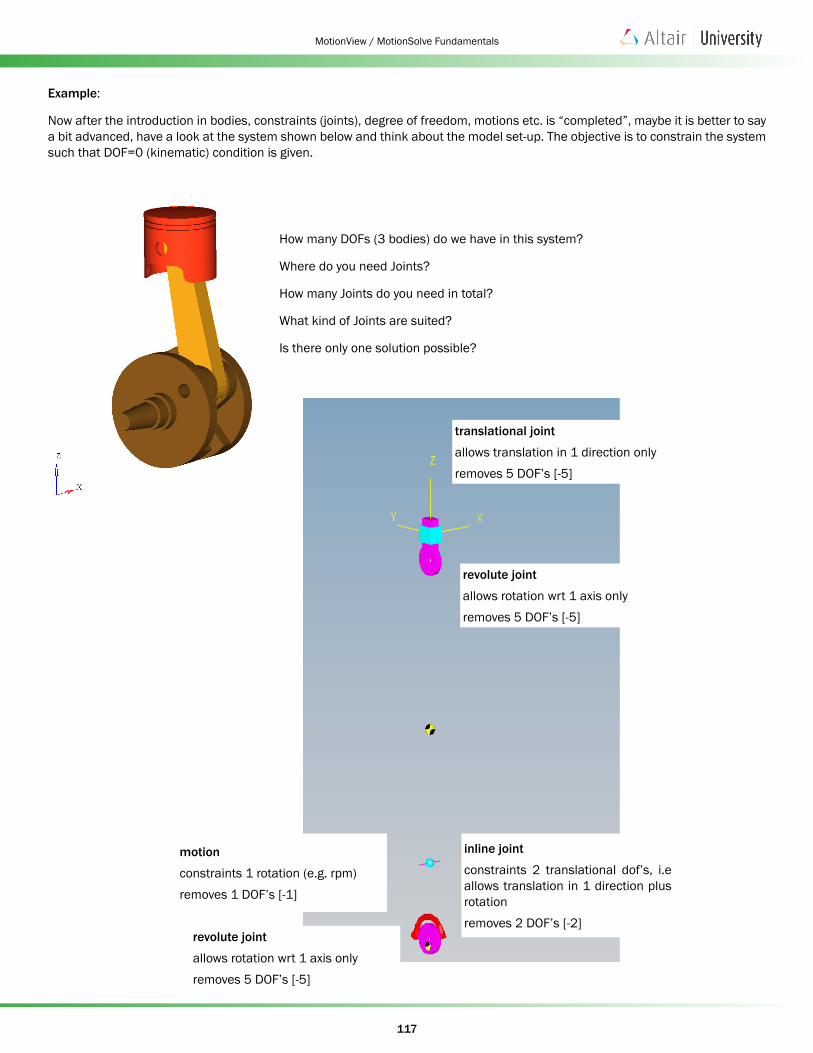
Now after the introduction in bodies, constraints (joints), degree of freedom, motions etc. is “completed”, maybe it is better to say a bit advanced, have a look at the system shown below and think about the model set-up. The objective is to constrain the system such that DOF=0 (kinematic) condition is given.
How many DOFs (3 bodies) do we have in this system?
Where do you need Joints?
How many Joints do you need in total?
What kind of Joints are suited?
Is there only one solution possible?
revolute joint
allows rotation wrt 1 axis onlyremoves 5 DOF’s [-5]
inline joint
constraints 2 translational dof’s, i.e allows translation in 1 direction plus rotationremoves 2 DOF’s [-2]
revolute joint
allows rotation wrt 1 axis onlyremoves 5 DOF’s [-5]
motion
constraints 1 rotation (e.g. rpm)removes 1 DOF’s [-1]
translational joint
allows translation in 1 direction onlyremoves 5 DOF’s [-5]

118
MotionView / MotionSolve Fundamentals
The system is characterized by 18 DOFs. The Joints & Motion constrain 18 DOFs (numbers in [ ..]. Thus, there is no remaining DOF and hence we are looking at a kinematically constrained system.
Alternatively, you may model the system as:
In this model setup the Inline Joint [-2 DOFs] located at the crankshaft-con-rod connection and the Revolute Joint [-5] at the piston-con-rod connection were replaced by a Cylindrical Joint [-4] and a Ball Joint [-3].
motion
constraints 1 rotation (e.g. rpm)removes 1 DOF’s [-1]
revolute joint
allows rotation wrt 1 axis onlyremoves 5 DOF’s [-5]
cylindrical joint
constraints 2 translational and 2 rotational dof’sremoves 4 DOF’s [-4]
ball joint
allows rotation onlyremoves 3 translational DOF’s [-3]
translational joint
allows translation in 1 direction onlyremoves 5 DOF’s [-5]
119
MotionView / MotionSolve Fundamentals
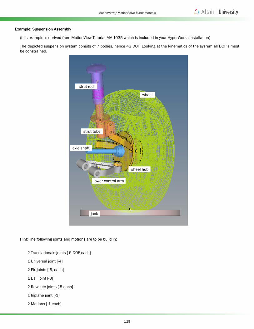
Example: Suspension Assembly
(this example is derived from MotionView Tutorial MV-1035 which is included in your HyperWorks installation)
The depicted suspension system consits of 7 bodies, hence 42 DOF. Looking at the kinematics of the sysrem all DOF’s must be constrained.
Hint: The following joints and motions are to be build in:
2 Translationals joints [-5 DOF each]
1 Universal joint [-4]
2 Fix joints [-6, each]
1 Ball joint [-3]
2 Revolute joints [-5 each]
1 Inplane joint [-1]
2 Motions [-1 each]
wheel
jack
wheel hub
lower control arm
axle shaft
strut rod
strut tube

120
MotionView / MotionSolve Fundamentals
The model check “reveals”:
universal joint [-4]
translational joint [-5]
fix joint [-6]
motion [-1]
motion [-1]translational joint [-5]
revolution joint [-5] revolution joint [-5]
ball joint [-5]
inplane joint [-5]

121
MotionView / MotionSolve Fundamentals
Redundant Constraints
It is possible to “over-specify” the constraints in a model. In this case, the system is said to be over-constrained, and the constraints are said to be “redundant”.
For instance, in our previous example, the constraint equation for x and y was:
x – y = 0
What if we add the equation?:
2x – 2y = 0
Clearly, you can see that this equation constrains X and Y identically to the first equation. Thus, this equation is redundant.
For a mechanical example, consider a door connected to a frame as shown in the figure below.
A Simple System With Redundant Constraints
Both the door and the frame are assumed to be rigid. Three hinges connect the door to the frame, allowing the door to open and close. The hinges are modeled as revolute joints. In this idealization, the hinges are assumed to be massless and rigid. Each hinge allows rotation between the door and the frame about an axis, shown as a red arrow in the Figure above.
In this idealization, a couple of points should be noted:
• The hinge axes are required to be perfectly collinear. Otherwise the door cannot be opened or closed.
• Only one hinge is truly necessary. The remaining two are “redundant”.
If such a system is provided to MotionSolve, it will detect a redundancy in the constraints and remove the equivalent of two hinges from the model. It will solve the system so that the correct motion is predicted.
Note: The effect of removing two hinges from the solution process is to set their reaction forces to zero. Clearly, this is unexpected behavior. In reality, all three hinges have reaction forces and torques. This is an issue with the idealization of the system. If at least one of two bodies, the door or the frame, were made flexible, then more realistic reactions would be observed at each hinge.
Avoid Redundant Constraints
It is extremely rare that a model requires the use of redundant constraints – there is usually a way to remove them, even if it is not obvious at first. Redundant constraints may work fine with the solver. But, occasionally, they can cause a constraint to be removed in a strange manner. If you see some strange results in your simulation, the first thing to always do is to remove any redundant constraints.
• Use joint primitives to precisely impose only the necessary constraints and avoid introducing redundant ones. This may require much thought in case of complex mechanisms.

122
MotionView / MotionSolve Fundamentals
Examples of redundant constraints:
• Rigid door with 2 or 3 revolute joints to model hinges (wrong)
- Correct modeling is: 1 revolute joint to door
- Degrees of freedom: 6 free body DOF’s – 5 constraints = 1 DOF
• Four-bar mechanism with 4 revolute joints (wrong)
- Correct modeling is: ground – revolute joint – part1 – ball joint – part2 – universal joint – part3 – revolute joint – ground
- Degrees of freedom: (3*6=)18 free body DOF’s – (5+3+4+5 =17) constraints = 1 DOF
• Build your models one constraint at a time for complicated mechanism, and use the MotionSolve messaging to help determine if/when you introduce a redundant constraint. Example MotionSolve message for the over-constrained four-bar mechanism with four revolute joints, which tells you that three redundant constrains exist, but there is one DOF for this model:
If the above step is not feasible, then consider using flexible bodies or replace idealized joints with bushings. Flexible bodies add degrees of freedom to your model and reduce the likelihood of a redundant constraint. They may also provide more accurate results.


![A novel six-degrees-of-freedom series-parallel … · A novel six-degrees-of-freedom series-parallel manipulator ... Kutzbach criterion [19], is capable to realize six degrees of](https://img.dokumen.tips/doc/110x75/5b79f3c77f8b9a703b8ebdd5/a-novel-six-degrees-of-freedom-series-parallel-a-novel-six-degrees-of-freedom.jpg)