Embed Size (px)
Citation preview
Rev. 3
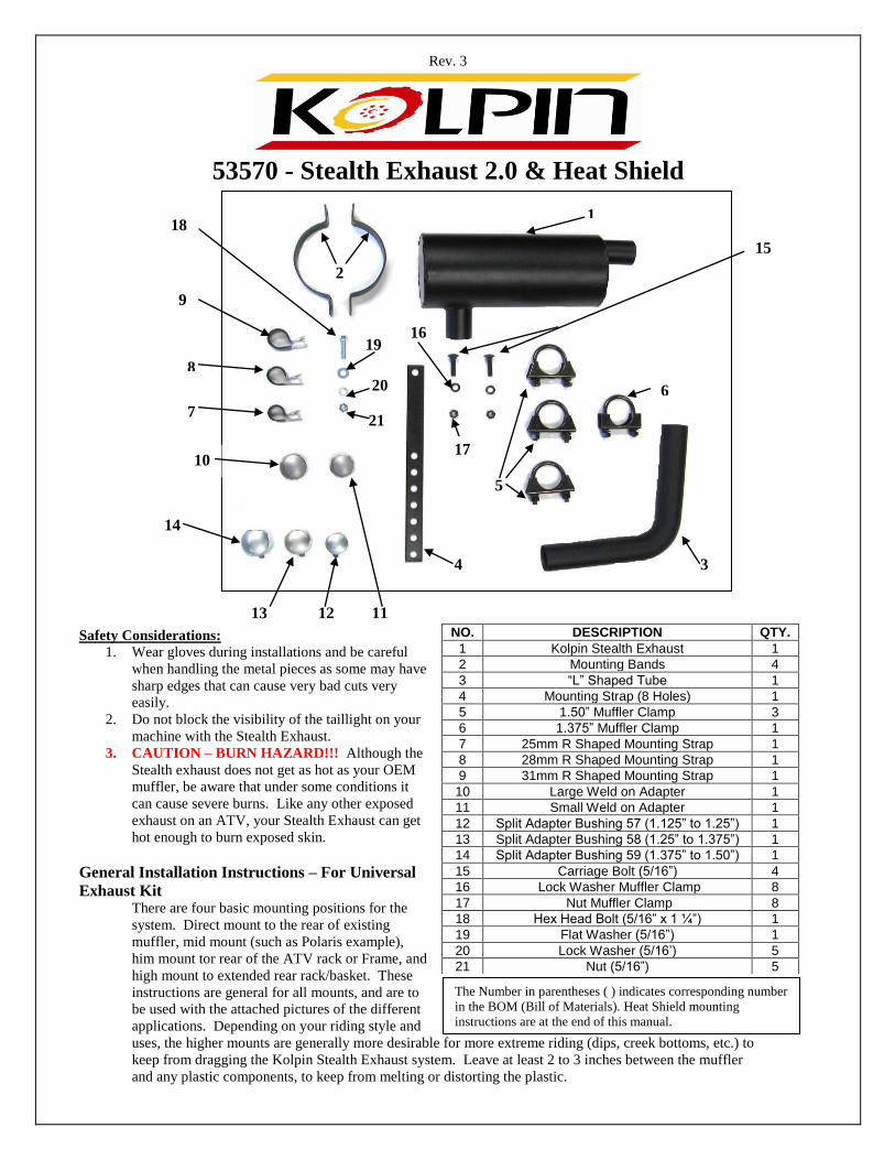
53570 - Stealth Exhaust 2.0 & Heat Shield
Safety Considerations:
1. Wear gloves during installations and be careful
when handling the metal pieces as some may have
sharp edges that can cause very bad cuts very
easily.
2. Do not block the visibility of the taillight on your
machine with the Stealth Exhaust.
3. CAUTION – BURN HAZARD!!! Although the
Stealth exhaust does not get as hot as your OEM
muffler, be aware that under some conditions it
can cause severe burns. Like any other exposed
exhaust on an ATV, your Stealth Exhaust can get
hot enough to burn exposed skin.
General Installation Instructions – For Universal
Exhaust Kit There are four basic mounting positions for the
system. Direct mount to the rear of existing
muffler, mid mount (such as Polaris example),
him mount tor rear of the ATV rack or Frame, and
high mount to extended rear rack/basket. These
instructions are general for all mounts, and are to
be used with the attached pictures of the different
applications. Depending on your riding style and
uses, the higher mounts are generally more desirable for more extreme riding (dips, creek bottoms, etc.) to
keep from dragging the Kolpin Stealth Exhaust system. Leave at least 2 to 3 inches between the muffler
and any plastic components, to keep from melting or distorting the plastic.
NO. DESCRIPTION QTY.
1 Kolpin Stealth Exhaust 1
2 Mounting Bands 4
3 “L” Shaped Tube 1
4 Mounting Strap (8 Holes) 1
5 1.50” Muffler Clamp 3
6 1.375” Muffler Clamp 1
7 25mm R Shaped Mounting Strap 1
8 28mm R Shaped Mounting Strap 1
9 31mm R Shaped Mounting Strap 1
10 Large Weld on Adapter 1
11 Small Weld on Adapter 1
12 Split Adapter Bushing 57 (1.125” to 1.25”) 1
13 Split Adapter Bushing 58 (1.25” to 1.375”) 1
14 Split Adapter Bushing 59 (1.375” to 1.50”) 1
15 Carriage Bolt (5/16”) 4
16 Lock Washer Muffler Clamp 8
17 Nut Muffler Clamp 8
18 Hex Head Bolt (5/16” x 1 ¼”) 1
19 Flat Washer (5/16”) 1
20 Lock Washer (5/16’) 5
21 Nut (5/16”) 5
1
2
9
8
7
3 4
5
6
10
14
13 12 11
15
18
16
17
19
20
21
The Number in parentheses ( ) indicates corresponding number
in the BOM (Bill of Materials). Heat Shield mounting
instructions are at the end of this manual.

Rev. 3
1. 1 3/8” or 1 ½” Outlet – The first step is to determine what is necessary to make the outlet on your ATV
exhaust have the 1 3/8” O.D. or 1 ½” O.D. male outlet needed to adapt to the Stealth Exhaust 2.0. For
ATV’s that have a male outlet, use the Adapter Bushings (12, 13, or 14 in BOM) in the kit (see instruction
supplement) to bush it up to the 1 ½” size. If your OEM outlet points down, you may need to cut it so it
points more directly out the rear of the machine. Be sure to leave the outlet long enough (at least 1 ½”) to
slide the bushings on it and attach the Stealth Exhaust 2.0. If you are mounting the Stealth Exhaust 2.0
directly to the existing outlet on your ATV (as in the pictures of the Yamaha Grizzly), use the smaller 1
3/8” muffler clamp for this connection. Also, use the high temp silicone (not included) for this type of
attachment.
For ATV’s (such as Honda) with no male outlet – Use the weld on adapters (10, or 11) See the
instruction supplement, or use our optional Bolt-On Adaptor, part number 53520
DIRECT MOUNT: Weld on the 1 3/8” O.D. adapter, and install the Stealth Exhaust directly over the adapter,
and clamp it with 1 3/8” Muffler Clamp.
HIGH MOUNT USING ELBOW ADAPTER. Weld on 1 ½” O.D. adapter; then the adapter elbow will slide
over the weld on adapter. Now clamp that using the 1 ½” muffler clamp. Hold the proper adapter centered over
the outlet and weld it in place. Wire feed or any type of light metal welding works well for this. If your OEM
muffler is stainless steel, generally Type 309 wire or rod works best. If you do not have welding capabilities,
most welding shops will do it for a minimal fee. It is suggested you disconnect the battery and ignition system,
and put the welding ground as close as possible to the weld area to prevent any damage to the ATV’s electrical
system. You can also remove your muffler to weld on the adapter. Weld on adapters can be used to adapt most
any ATV to the Stealth Exhaust 2.0.
BOLT ON ADAPTER 53520: A universal bolt on adapter is available for many applications, such as the
Honda Rancher 300, the Forman 400 and 450, or any ATV with a flat or concave outlet on the OEM muffler.
There is also a bolt on adapter available specifically for the Honda Rubicon (53530) while supplies last.
2. Mount Muffler – Determine how and where you want to mount your Stealth Exhaust 2.0 and install it
using the rubber coated mounting clamps and the Mounting Bands (2)) in the kit. Select the proper rubber
coated clamps, (there are three sizes, 8, 9, or 10 depending on your rack Diameter), for the frame or rear rack on
your ATV and slide the clamp over the over that. Then install the Mounting Bands (4) over the muffler using
the supplied Bolts and Nuts (15, 16, and 17) and hang it in place, using the 8 holed Mounting Strap (4), which
you can bend, cut or drill to better accommodate your needs for your application. Hang the Stealth Exhaust2.0
in place, but do not tighten at this point.
2. 80 Degree Adapter Elbow Connection(3) – Hold the special adapter elbow in place, between the
ATV’s muffler outlet and the Stealth Exhaust inlet. Determine where to cut the adapter elbow to fit. BE
CAREFUL NOT TO CUT THE ADAPTER TOO SHORT! Cut the adapter to fit with a hack saw.
WARNING: Do not distort the tube by clamping it too tight in a vice! Be sure to clean the burs from the
cut end with a file or some sandpaper. This will also allow the pipe to slide on easily. To assemble the
elbow into place, you will have to loosen the muffler hanger or take the muffler back off. The next step is
to put the adapter in place and make sure it fits correctly. Attach it using the 1 ½” clamps form the kit.
Again, you can use some orange hi-temp sealant on this connection. Now, reassemble your muffler and
hangers into place and tighten all mounts and clamps. Cutting 4 small slices in the pipe will allow the pipe
to tighten more securely.
Direct Mount – If your ATV already has a male outlet, simply slide the supplied bushings on your ATV
outlet and install the Stealth Exhaust directly on it using the smaller 1 3/8” muffler clamp. (See Grizzly
Pictures). For a direct mount to the rear of the ATV’s muffler with the installed 1 3/8” weld on outlet, use the
1 3/8” muffler clamp. You can use some high temp silicone on this connection and on the bushings.
Rev. 3
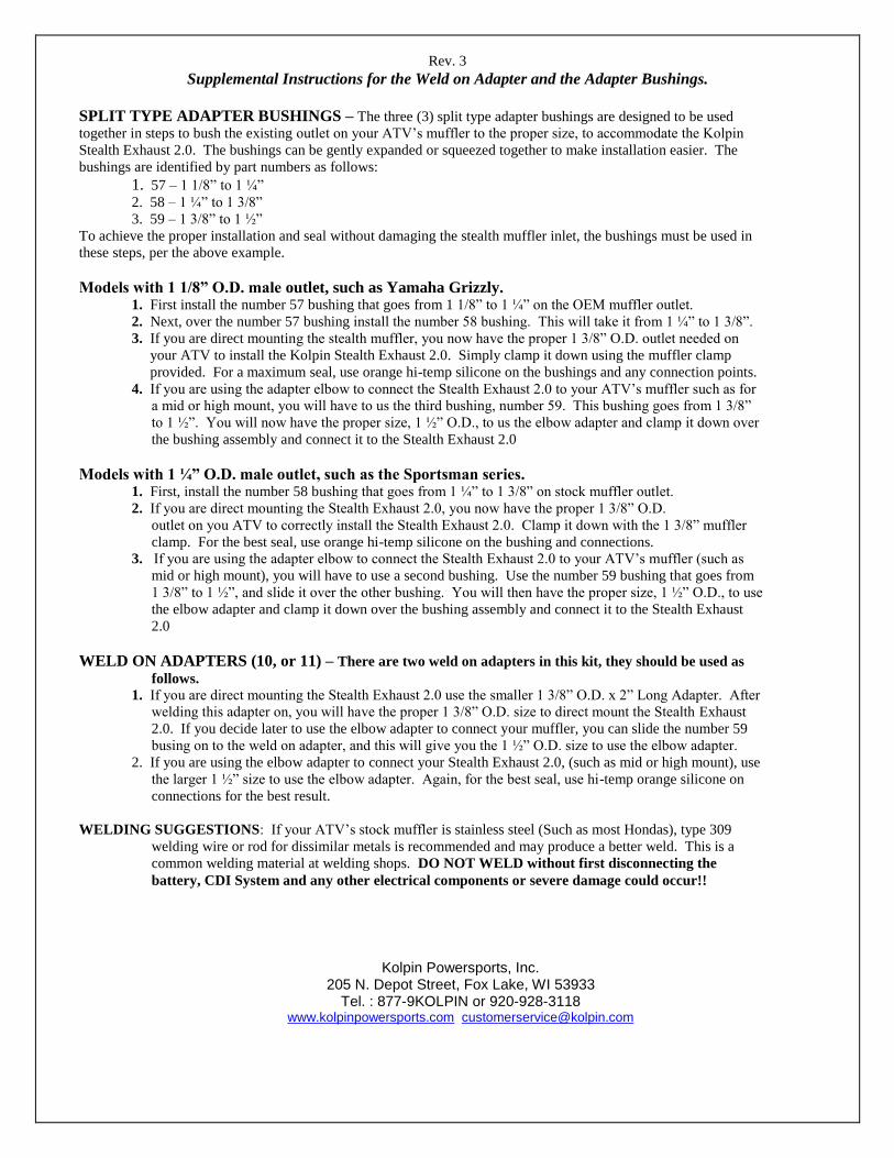
Supplemental Instructions for the Weld on Adapter and the Adapter Bushings.
SPLIT TYPE ADAPTER BUSHINGS – The three (3) split type adapter bushings are designed to be used
together in steps to bush the existing outlet on your ATV’s muffler to the proper size, to accommodate the Kolpin
Stealth Exhaust 2.0. The bushings can be gently expanded or squeezed together to make installation easier. The
bushings are identified by part numbers as follows:
1. 57 – 1 1/8” to 1 ¼”
2. 58 – 1 ¼” to 1 3/8”
3. 59 – 1 3/8” to 1 ½”
To achieve the proper installation and seal without damaging the stealth muffler inlet, the bushings must be used in
these steps, per the above example.
Models with 1 1/8” O.D. male outlet, such as Yamaha Grizzly. 1. First install the number 57 bushing that goes from 1 1/8” to 1 ¼” on the OEM muffler outlet.
2. Next, over the number 57 bushing install the number 58 bushing. This will take it from 1 ¼” to 1 3/8”.
3. If you are direct mounting the stealth muffler, you now have the proper 1 3/8” O.D. outlet needed on
your ATV to install the Kolpin Stealth Exhaust 2.0. Simply clamp it down using the muffler clamp
provided. For a maximum seal, use orange hi-temp silicone on the bushings and any connection points.
4. If you are using the adapter elbow to connect the Stealth Exhaust 2.0 to your ATV’s muffler such as for
a mid or high mount, you will have to us the third bushing, number 59. This bushing goes from 1 3/8”
to 1 ½”. You will now have the proper size, 1 ½” O.D., to us the elbow adapter and clamp it down over
the bushing assembly and connect it to the Stealth Exhaust 2.0
Models with 1 ¼” O.D. male outlet, such as the Sportsman series. 1. First, install the number 58 bushing that goes from 1 ¼” to 1 3/8” on stock muffler outlet.
2. If you are direct mounting the Stealth Exhaust 2.0, you now have the proper 1 3/8” O.D.
outlet on you ATV to correctly install the Stealth Exhaust 2.0. Clamp it down with the 1 3/8” muffler
clamp. For the best seal, use orange hi-temp silicone on the bushing and connections.
3. If you are using the adapter elbow to connect the Stealth Exhaust 2.0 to your ATV’s muffler (such as
mid or high mount), you will have to use a second bushing. Use the number 59 bushing that goes from
1 3/8” to 1 ½”, and slide it over the other bushing. You will then have the proper size, 1 ½” O.D., to use
the elbow adapter and clamp it down over the bushing assembly and connect it to the Stealth Exhaust
2.0
WELD ON ADAPTERS (10, or 11) – There are two weld on adapters in this kit, they should be used as
follows.
1. If you are direct mounting the Stealth Exhaust 2.0 use the smaller 1 3/8” O.D. x 2” Long Adapter. After
welding this adapter on, you will have the proper 1 3/8” O.D. size to direct mount the Stealth Exhaust
2.0. If you decide later to use the elbow adapter to connect your muffler, you can slide the number 59
busing on to the weld on adapter, and this will give you the 1 ½” O.D. size to use the elbow adapter.
2. If you are using the elbow adapter to connect your Stealth Exhaust 2.0, (such as mid or high mount), use
the larger 1 ½” size to use the elbow adapter. Again, for the best seal, use hi-temp orange silicone on
connections for the best result.
WELDING SUGGESTIONS: If your ATV’s stock muffler is stainless steel (Such as most Hondas), type 309
welding wire or rod for dissimilar metals is recommended and may produce a better weld. This is a
common welding material at welding shops. DO NOT WELD without first disconnecting the
battery, CDI System and any other electrical components or severe damage could occur!!
Kolpin Powersports, Inc. 205 N. Depot Street, Fox Lake, WI 53933
Tel. : 877-9KOLPIN or 920-928-3118 www.kolpinpowersports.com [email protected]

Rev. 3
UNIVERSAL BOLT ON ADAPTER – 1 3/8” O.D. Fits Honda 300. 350, 400, 450 and other makes/models with flat or concave outlet.
INSTALLATION INSTRUCTIONS:
This adapter is designed for use on most all ATV applications where the original equipment muffler outlet has a flat or
concave surface, and no male pipe outlet.
1. Hold the adapter centered over the exhaust outlet and mark the four mounting holes with scribe or marking
pen, and the center punch holes.
2. Drill the four holes with a 1/8” bit.
3. Using a 3/16” pin punch or awl, like that shown in the picture, hammer the punch into each hole to enlarge it
to the size that will accept the ¼” self tapping screws. This rolls some of the metal into the hole, and will
make the self-tapping screws grip better. Be very careful not to enlarge the holes past the maximum of
3/16”, or the self-tapping screw may not tighten properly.
4. If your application has a concave surface on the muffler outlet, it is probably a good idea to use the supplied
gasket with some orange high temp silicone. Hold the gasket in place for a short time until the sealer gets
tacky. After the silicone has dried enough to hold the gasket in place, apply the high-temp silicone liberally
to both mounting surfaces and the bolt holes. Now go to step 6.
5. If your application has a flat surface on the muffler outlet, you probably don’t need the gasket, just apply the
high-temp silicone liberally to both surfaces and the mounting holes.
6. Hold the adapter in place. Using a ratchet and socket start the self tapping screws by pushing on them and
turning them at the same time. You may have to tap the screw lightly with a hammer to get them started.
Tighten the screws securely, but use care not to over tighten to the point of stripping the threads.
7. This adapter has a 1 3/8” O.D. so the Stealth Exhaust 2.0 can now slide over it and be installed direct, using
the 1 3/8” muffler clamp in your kit.
8. IMPORTANT: If you are using the 80 degree adapter elbow pipe for the connection between the bolt on
adapter and the Stealth Exhaust 2.0, you must slide the #59 Split Bushing, from your Exhaust kit, onto the
bolt on adapter outlet before installing the elbow. This sleeves the outlet to the proper 1 ½” size needed to
install the elbow. HI-TEMP SILICONE can be used on connections for maximum sealing, but this is NOT
mandatory!
__________________________________________________________________________________________________
NOTE: Additional Mounting Instructions and Applications can be found on the Kolpin website, at www.kolpin.com

Rev. 3
INSTALLATION
Drill 1/8” Holes Mark Holes
Enlarge holes with 3/16” pin punch such as one
shown. This rolls metal inside to make screws grip
better.
Glue gasket in place with HI-TEMP silicone and
apply silicone to all surfaces and screw holes
Bolt adapter in place. For direct installation –
muffler will slide directly over this adapter. Use
1 3/8” muffler clamp.
To use elbow adapter, slide #59 bushing onto the
outlet as shown. This make it 1 ½” O.D. needed
for use with elbow. Use sealant.

Rev. 3
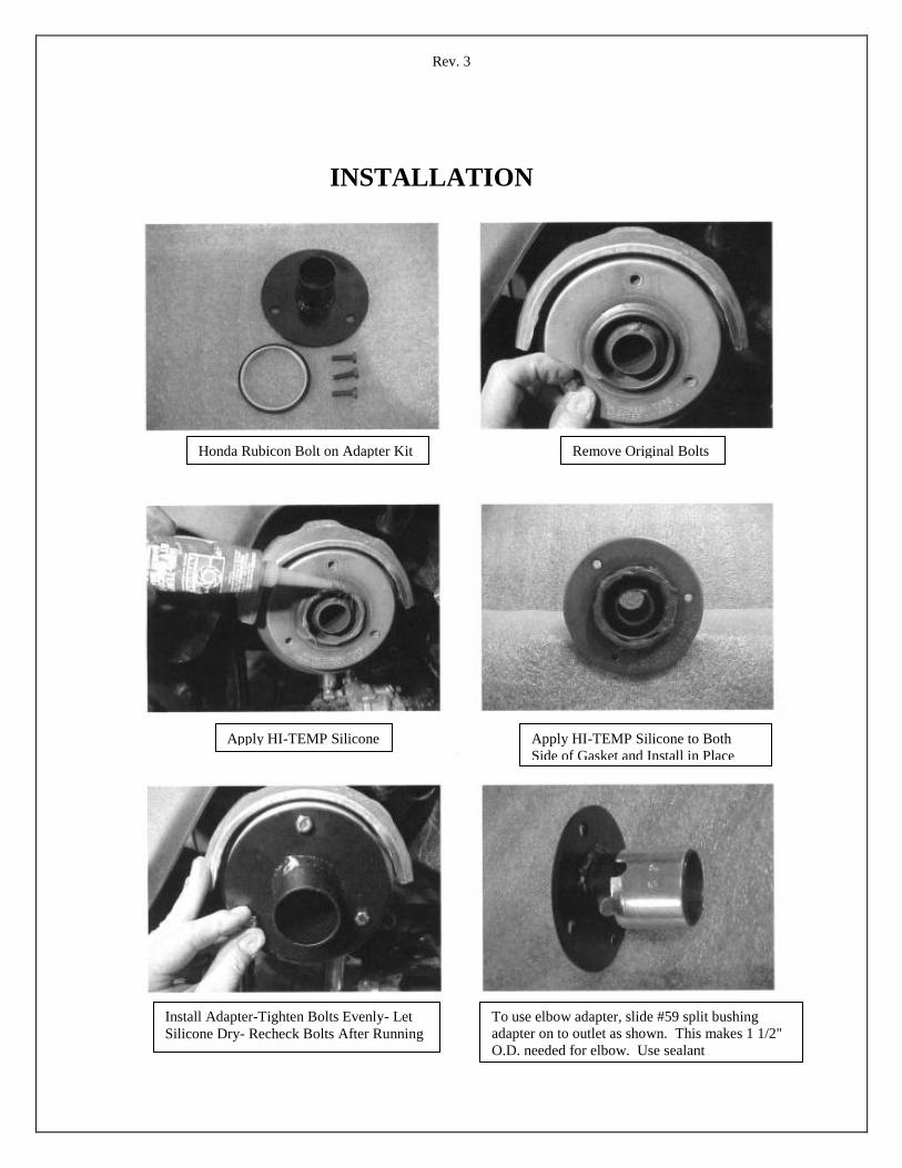
HONDA RUBICON BOLT ON ADAPTER WITH 1 3/8” O.D. OUTLET
INSTALLATION INSTRUCTIONS:
1. Carefully remove the original equipment spark arrester bolts. These bolts may try to seize and break off as
you try to remove them. Use penetrating oil and work the bolts back and forth till they will come out
without breaking. It is not necessary to remove the spark arrester, but make sure the gasket behind it stays in
place.
2. Apply Orange Hi-Temp Silicon liberally to the rear of the spark arrester, where the adapter and gasket will
contact it. Apply silicone sealant to both sides of the gasket and install in place on the muffler.
3. Apply anti-seize compound to the threads of the 6 x 20mm replacement bolts supplied in the kit.
4. Again, make sure gasket behind the spark arrester is in place and make sure the new gasket for the adapter is
in place. Then hold the adapter in place being careful to get it exactly in place the first time. Start all 6 x
20mm replacement bolts and turn them in and tighten them evenly. It is important that these bolts be
tightened evenly so the adapter seals properly all the way around.
5. Let the silicone dry while you finish the installation of the Stealth Exhaust 2.0. It is important that the
silicone has adequate time to dry before starting the machine. Check the tightness of the mounting bolts
again, both before and after starting the machine.
6. This adapter has a 1 3/8” O.D. so the Stealth Exhaust 2.0 can now slide over it and be installed direct, using
the 1 3/8” muffler clamp in your kit.
7. IMPORTANT: If you are using the 80 degree adapter elbow pipe for the connection between the bolt on
adapter and the Stealth Exhaust 2.0, you must slide the #59 Split Bushing, from your Exhaust kit, onto the
bolt on adapter outlet before installing the elbow. This bushes the outlet up to the proper 1 ½” size needed
to install the elbow. ALWAYS USE HI-TEMP SILICONE ON ALL CONNECTIONS FOR MAXIMUM
NOISE REDUCTION.
__________________________________________________________________________________________________
Suzuki King Quad
1. Remove the Heat Shield and Spark Arrestor from the muffler by removing the three screws at the outlet.
2. Using the smaller WELD-ON ADAPTOR supplied with the Stealth kit, place this over the stock outlet as shown in
the picture and weld in place.
3. Install the modified Spark Arrestor back into the muffler canister on the machine, install the heat shield and secure
with the three screws. The Stealth muffler can now be clamped directly to the outlet with no adaptors required.
Secure the muffler body to the chassis using the band clamps, strap and vinyl coated band clamp of your choice and
go riding!
Rev. 3
INSTALLATION
Honda Rubicon Bolt on Adapter Kit Remove Original Bolts
Apply HI-TEMP Silicone Apply HI-TEMP Silicone to Both
Side of Gasket and Install in Place
Install Adapter-Tighten Bolts Evenly- Let
Silicone Dry- Recheck Bolts After Running
To use elbow adapter, slide #59 split bushing
adapter on to outlet as shown. This makes 1 1/2"
O.D. needed for elbow. Use sealant

Rev. 3
YAMAHA RHINO INSTALLATION
1. To install the Stealth Exhaust 2.0 correctly on the Rhino the outlet must be changed to point down instead of angled
to the right. This can be done by welding on the 1 3/8” weld on adapter as shown in the first picture or by removing
the spark arrester and drill new holes so it can be rotated to point down. This is shown in the top right picture.
Redrilling is the simplest solution.
2. Apply HI-TEMP Silicone sealant and install the middle sized #58 split adapter bushing as shown.
3. Assemble the hangers to the exhaust and install by bending hangers as shown. Drill holes for hanger bolts in the
cross member and attach using the bolt and nut supplied.
4. Push muffler as far on outlet as possible, then tilt the dump box to check for clearance. Also, be sure to check the tire
clearance. Adjust the angle of the exhaust as needed and install and tighten the 1 3/8” muffler clamp. Run engine
and retighten the muffler clamp securely.
5. Check to make sure your clearances are still there. FYI-you may need an extension for the hitch.
6. NOTE some pictures are from our original Stealth Exhaust system that utilized a longer canister. Also, the new
shorter Stealth 2.0 only utilizes one hanger strap instead of the two in the picture.
Rev. 3
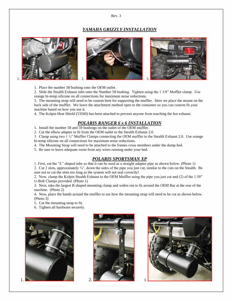
YAMAHA GRIZZLY INSTALLATION
1. 2. 3.
1. Place the number 58 bushing onto the OEM outlet.
2. Slide the Stealth Exhaust inlet onto the Number 58 bushing. Tighten using the 1 3/8” Muffler clamp. Use
orange hi-temp silicone on all connections for maximum noise reductions.
3. The mounting strap will need to be custom bent for supporting the muffler. Here we place the mount on the
back side of the muffler. We leave the attachment method open to the consumer so you can custom fit your
machine based on how you use it.
4. The Kolpin Heat Shield (53560) has been attached to prevent anyone from touching the hot exhaust.
POLARIS RANGER 6 x 6 INSTALLATION 1. Install the number 58 and 59 bushings on the outlet of the OEM muffler.
2. Cut the elbow adapter to fit from the OEM outlet to the Stealth Exhaust 2.0.
3. Clamp using two 1 ½” Muffler Clamps connecting the OEM muffler to the Stealth Exhaust 2.0. Use orange
hi-temp silicone on all connections for maximum noise reductions.
4. The Mounting Strap will need to be attached to the frames cross members under the dump bed.
5. Be sure to leave adequate room from any wires running under your bed.
POLARIS SPORTSMAN XP 1. First, cut the “L” shaped tube so that it can be used as a straight adapter pipe as shown below. (Photo 1)
2. Cut 2 slots, approximately ¾”, down the sides of the pipe you just cut, similar to the cuts on the Stealth. Be
sure not to cut the slots too long as the system will not seal correctly!
2. Now, clamp the Kolpin Stealth Exhaust to the OEM Muffler using the pipe you just cut and (2) of the 1.50”
U-Bolt Clamps provided. (Photo 1)
3. Next, take the largest R shaped mounting clamp and widen out to fit around the OEM Bar at the rear of the
machine. (Photo 2)
4. Now, place the bands around the muffler to see how the mounting strap will need to be cut as shown below.
(Photo 3)
5. Cut the mounting strap to fit.
6. Tighten all hardware securely.
1. 2. 3.

Rev. 3
POLARIS RZR (2008 Model Year) INSTALLATION
Remove the existing hex bolt from the OEM
muffler as shown.
Grind the access material sticking up inside the
tailpipe from where the existing bolt was threaded.
This allows the Kolpin Muffler to slide in easily.
Next, drill back through the stealth and
replace the self tapping OEM Bolt to secure
the Stealth.
Now, place the 25mm and 28mm “R” strap around the frame
tube. Attach the Mounting Strap to “R” Straps. Note: Straps
will have to be bent to fit as shown. Bolt using the hardware
provided.
Kolpin Powersports, Inc. 205 N. Depot Street, Fox Lake, WI 53933
Tel. : 877-9KOLPIN or 920-928-3118 www.kolpinpowersports.com [email protected]
Final look using the Kolpin Stealth Exhaust with Heatshield.

Rev. 3
Stealth Heat Shield Installation
Heat Shield Mounting Instructions:
1. The heat shield attaches using the 4 Mounting Bands
included with the kit. Use the 4 Carriage Bolts (7) on each
side (top and bottom) of the Mounting Bands as shown in the
picture, secure with 4 lock washers and nuts. (8 & 9)
2. The Kolpin Heat Shield has three slots (top and bottom) to make
it easier to center the shield over the muffler, no matter what position
your muffler is located. (1)
3. To complete the installation, attach the proper size vinyl-coated strap to a frame
tube and attach the 8- hole mounting strap using the supplied hex bolt, washer, lock
washer and nut. The other side of the strap mounts to the muffler. NOTE: this strap
is designed to be cut to length if needed.
Kolpin Powersports, Inc. 205 N. Depot Street, Fox Lake, WI
Phone #: (877) 9KOLPIN or (920) 928-6514
www.kolpinpowersports.com [email protected]
NO. DESCRIPTION QTY.
1 Kolpin Heat Shield 1
2 Mounting Bands 4
3 Mounting Strap (8 Holes) 1
4 25mm R Shaped Mounting Strap 1
5 28mm R Shaped Mounting Strap 1
6 31mm R Shaped Mounting Strap 1
7 Carriage Bolt (5/16 x 1 ¼” 4
8 Hex Head Bolt (5/16” x 1 ¼”) 1
9 Flat Washer (5/16”) 1
10 Lock Washer (5/16”) 5
11 Nut (5/16”) 5
1
3
2
7
10
0
11
8
9
10
11
6
5
4
Rev. 3
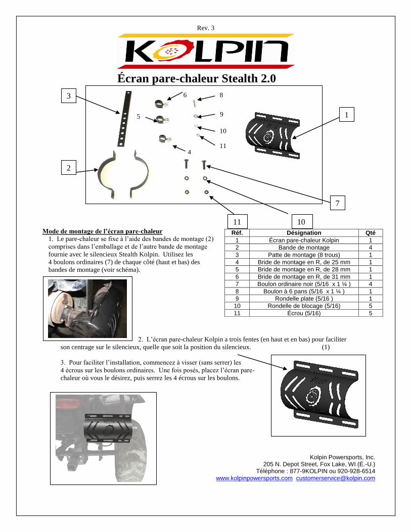
Écran pare-chaleur Stealth 2.0
Mode de montage de l’écran pare-chaleur
1. Le pare-chaleur se fixe à l’aide des bandes de montage (2)
comprises dans l’emballage et de l’autre bande de montage
fournie avec le silencieux Stealth Kolpin. Utilisez les
4 boulons ordinaires (7) de chaque côté (haut et bas) des
bandes de montage (voir schéma).
2. L’écran pare-chaleur Kolpin a trois fentes (en haut et en bas) pour faciliter
son centrage sur le silencieux, quelle que soit la position du silencieux. (1)
3. Pour faciliter l’installation, commencez à visser (sans serrer) les
4 écrous sur les boulons ordinaires. Une fois posés, placez l’écran pare-
chaleur où vous le désirez, puis serrez les 4 écrous sur les boulons.
Kolpin Powersports, Inc. 205 N. Depot Street, Fox Lake, WI (É.-U.)
Téléphone : 877-9KOLPIN ou 920-928-6514
www.kolpinpowersports.com [email protected]
Réf. Désignation Qté
1 Écran pare-chaleur Kolpin 1
2 Bande de montage 4
3 Patte de montage (8 trous) 1
4 Bride de montage en R, de 25 mm 1
5 Bride de montage en R, de 28 mm 1
6 Bride de montage en R, de 31 mm 1
7 Boulon ordinaire noir (5/16 x 1 ¼ ) 4
8 Boulon à 6 pans (5/16 x 1 ¼ ) 1
9 Rondelle plate (5/16 ) 1
10 Rondelle de blocage (5/16) 5
11 Écrou (5/16) 5
1
3
2
7
10 11
8
9
10
11
6
5
4