Embed Size (px)
Citation preview

Preparatory Survey (II) on Karachi Circular Railway Revival Project Final Report
JICA 5-84 NK-YEC-JEC
5.3 Power Supply Facilities
5.3.1 System Configuration
(1) Overall Power Supply System for KCR
Power supply facilities are composed of transmission line system, traction power substation system, power distribution system and overhead contact system.
Electric power required for KCR operation will be supplied from Liyari and Alladin Park Traction Substation (TSS) connected to Mauripur and KDA grid station of Karachi Electric Supply Company (KESC) through dedicated transmission lines which will be newly constructed only for KCR. Electric power required for KCR is divided into two categories, one is traction power for electric car operation and the other one is service power for the various facilities such as Operation Control Center (OCC), railway stations, rolling stock depot and signaling & telecommunication system.
Traction power supply system applied to KCR is that two TSSs are installed and they receive power from different grid stations of KESC’s network through dedicated double transmission lines. This system ensures more reliable power supply for KCR.
At TSS, three-phase high voltage AC of 132kV or 220kV from KESC grid station is transformed into single-phase AC of 25kv which is fed to electric cars through overhead contact line.
Feeding circuit of traction power is separated at Sectioning Post (SP) due to the different phase of power because each TSS receives power from KESC’s different grid station.
However in case power failure occurs at one of TSSs, system enables the other TSS to supply traction power to entire feeding circuit by connecting the circuit breakers of SPs.
Furthermore, service power of three-phase AC of 11kV is also supplied from TSS through dedicated distribution lines to those facilities such as OCC, railway stations, rolling stock depot and signaling & telecommunication system.
(2) Overview of Power Supply Reliability
Although KESC’ power supply system has been facing demand and supply gap due to power shortage, it can be expected that KCR will be supplied with fairly stable power supply taking into account the following issues below. Firstly, KESC ensures priority power supply to KCR with special agreement under the policy of supplying uninterrupted power to strategic customers that are not subject to any planned load shedding based on the exemption regulation. According to the KESC’s performance of Karachi Water & Sewerage Board (KWSB) which has been designated as strategic customer because of its public purpose same as KCR, power supply to KWSB has been quite satisfactory. Furthermore, another example shows that one big factory as industrial customer which has been receiving electric power of 220 kV through dedicated distribution system similar to KCR has not experienced any power shutdown since 2009.
Secondly, KESC is expected to continue the development work to improve the gap between demand and supply within the KESC’s service area. According to performance of enhancing generation capacity, KESC has recently added about 400MW and 500MW generation capacity into system as mentioned in Chapter 2.4.5.
Thirdly, power supply system of two TSSs and different grid stations of KESC’s which is applied to KCR will strengthen the capability of reliable power supply.
Because in case power failure occurs at one of TSSs, the other TSS can supply traction power to entire KCR feeding circuit by connecting the circuit breaker of SPs. Accordingly train operation can be maintained with uninterrupted power supply from TSS. Moreover it wouldn’t be anticipated that
Preparatory Survey (II) on Karachi Circular Railway Revival Project Final Report
JICA 5-85 NK-YEC-JEC
power failure occurs in both TSSs at the same time other than quite serious power supply trouble occurs in KESC’s transmission network.
Fourthly, reliability of electric power supply facilities such as transmission line, overhead contact system and TSSs & SPs should be maintained with proper maintenance work. Therefore KUTC should conduct adequate maintenance and repair work after completion of electric facilities. Furthermore, to avoid trouble of wire breakage and theft of overhead contact line, transmission line and other electric wires & cables, these facilities located at easily accessible place should be protected by fence, netting and other proper measures.
(3) Control System of Electric Facilities
Electric facilities of TSS & SP and power distribution system are controlled by Supervisory Control and Data Acquisition (SCADA). Main control device of SCADA is installed at OCC in Alladin Park rolling stock depot and terminal control device of SCADA is installed at TSS, SP and each railway station.
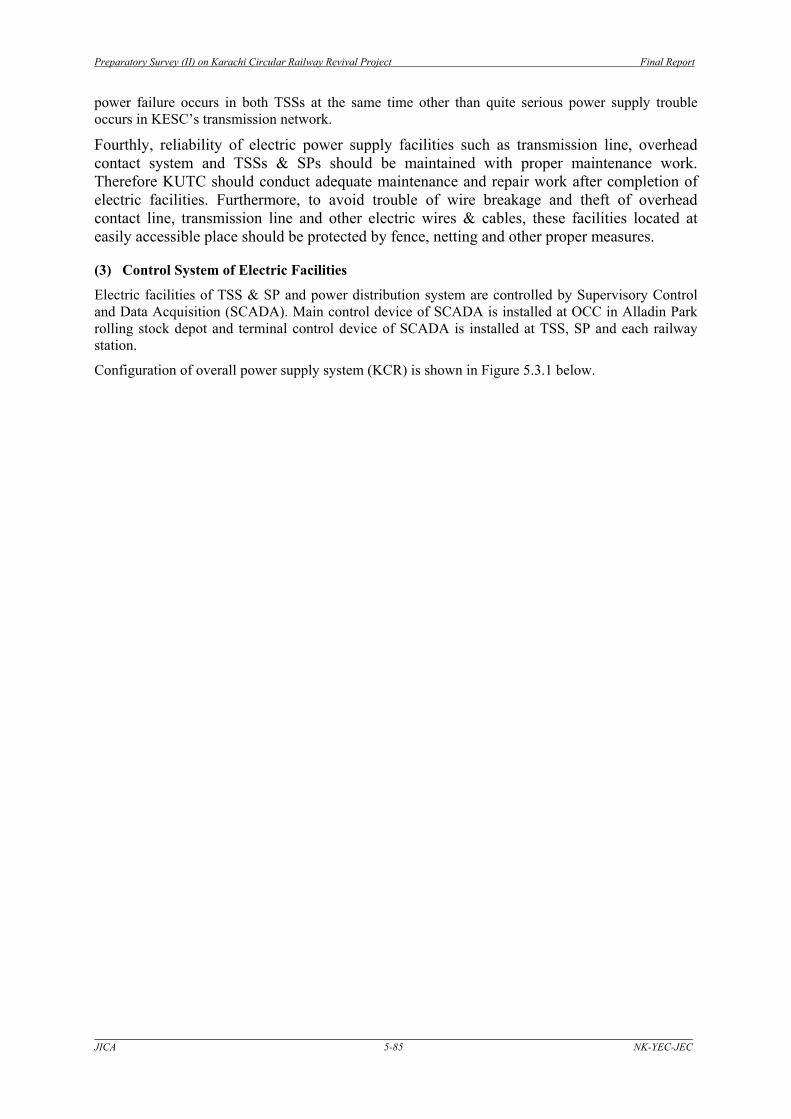
Configuration of overall power supply system (KCR) is shown in Figure 5.3.1 below.

Preparatory Survey (II) on Karachi Circular Railway Revival Project Final Report
JICA 5-86 NK-YEC-JEC
SITE
Manghopir
Orangi
North N
azimabad
Liaquatabad
Yasinabad
Giliani
Nipa
Alladin P
ark
Johar
Drigh R
oad
20K330M000
18K430M000
16K190M000
14K730M000
12K570M000
11K510M000
9K410M000
7K510M000
5K830M000
4K970M000
0K000M000
Depot-Hill
HBL16K890M000
Karach
i City
Wazir
Mansio
n
Liyari
Baldia
Shah Abdul L
atif
29K630M000
26K530M000
25K170M000
23K850M000
22K390M000
Wazir
Mansio
n
Tower
28K330M000
Karsaz H
alt
Chanesar
Naval
Karach
i Cantt.
DCOS
40K390M000
38K250M000
36K530M000
34K670M000
33K430M000
31K630M000
Shaheed-e-M
illat
Drigh R
oad
43K210M903
Source: JICA Study team
Figure 5.3.1 Configuration of Overall Power Supply System (KCR)
Preparatory Survey (II) on Karachi Circular Railway Revival Project Final Report
JICA 5-87 NK-YEC-JEC
This figure shows details of entire KCR configuration such as chainage, station location, track alignment, KESC’s grid station, KCR’s traction power substation, traction power feeding system, overhead contact system, power distribution system and SCADA.
AC2×25kV system (AT Feeding System) was planned in the previous study SAPROF (I). Results of careful examination of feeding system in a comprehensive way identified that AC 2×25kV (AT Feeding System) is most preferable feeding system which has a great advantage in terms of communication interference. Because KCR route is located very closely to busy commercial and dense residential area therefore communication interference caused by AC feeding system should be reduced to the lowest level to maintain the communication environment in good condition.
As a result of study on feeding system, it was agreed and confirmed that AC2 x 25kV system (AT Feeding System) is applied to KCR.
Composition of AC2 x 25kV Feeding System (AT Feeding System)
Normally AT Feeding System is composed of the following facilities.
A. Traction substation (TSS) that receives electric power from existing grid station and supplies power to electric cars through overhead contact system for train operation.
B. Sectioning post (SP) that separates the feeding circuit due to the difference of phase and voltage of electric power supplied from different TSSs.
C. Sub sectioning post (SSP) that is arranged between TSS and SP, if it is required to separate the feeding circuit into smaller sections.
In case of KCR, since average feeding distance between TSS and SP is only about 10kM, SSP is considered to be not necessary in the feeding circuit.
(4) Location of KESC’s Grid Station and KCR’s TSS
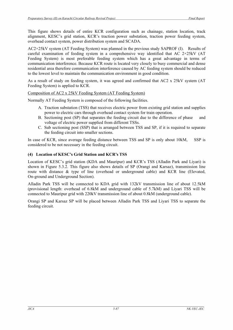
Location of KESC’s grid station (KDA and Mauripur) and KCR’s TSS (Alladin Park and Liyari) is shown in Figure 5.3.2. This figure also shows details of SP (Orangi and Karsaz), transmission line route with distance & type of line (overhead or underground cable) and KCR line (Elevated, On-ground and Underground Section).
Alladin Park TSS will be connected to KDA grid with 132kV transmission line of about 12.5kM (provisional length: overhead of 6.8kM and underground cable of 5.7kM) and Liyari TSS will be connected to Mauripur grid with 220kV transmission line of about 0.8kM (underground cable).
Orangi SP and Karsaz SP will be placed between Alladin Park TSS and Liyari TSS to separate the feeding circuit.

Preparatory Survey (II) on Karachi Circular Railway Revival Project Final Report
JICA 5-88 NK-YEC-JEC
Source: JICA Study team
Figure 5.3.2 Location of KESC’s Grid Station and KCR’s TSS
(5) Power Supply System to Depot
Rolling stock depot will be constructed at Wazir Mansion and Depot Hill. Electric power for rolling stock depot is supplied not through feeding circuit of main line but through dedicated feeding line from TSS. Because rolling stock depot needs electric power for daily car inspection, car washing and shunting work after power supply for main line is stopped due to maintenance and repair work. However in case power supply trouble occurs on dedicated feeding line, rolling stock depot can be supplied with electric power through feeding circuit of main line.
The length of dedicated feeding line will be approximately 2kM from Liyari TSS to Wazir Mansion depot and 4.5kM from Alladin Park TSS to Depot Hill depot respectively. These dedicated feeding lines will be controlled independently by OCC.

Preparatory Survey (II) on Karachi Circular Railway Revival Project Final Report
JICA 5-89 NK-YEC-JEC
5.3.2 Traction Substation (TSS) and Sectioning Post (SP) With regard to traction power supply, two TSSs are required to meet the high load demand for the train operation and also to maintain train operation service in case power failure occurs at one of TSSs. The other TSS has to supply traction power to entire KCR feeding circuit to maintain the operation service without any inconvenience to the passengers. The followings should be taken into consideration as an essential requirement for TSS.
Traction power system of TSS has sufficient capacity to supply the maximum KCR load of both traction power and service power required for the facilities of OCC, railway stations, rolling stock depot and signaling & telecommunication system.
TSS can supply adequate electric power to maintain a minimum voltage at pantograph point of the overhead contact system for safe and stable train operation.
In case electrical fault occurs, fault current in feeding circuit must be detected and blocked instantly to protect feeding system.
TSS should be placed close to KESC grid station to reduce installation cost of transmission line. Land area required for TSS is approximately 12,000m2.
The following items were examined to find out suitable location for TSS and to estimate the construction cost of transmission line.
(1) Location of Traction Substation (TSS)
In SAPROF (I), locations of proposed TSS are near Wazir Manison and Liyari railway station. Possible TSS locations including proposed locations above were carefully examined in terms of reliability of power supply from KESC grid station and land availability for TSS facilities. From the viewpoint of cost reduction of transmission line, location of TSS should be close to KESC grid station. Results of examination on possible TSS locations are as follows.
1) Liyari TSS
Liyari TSS has been selected out from proposed locations such as Wazir Mansion, Baldia and Liyari.
Regarding proposed locations, initially JICA Study Team examined the land availability close to Wazir Mansion railway station as proposed in SAPROF (I). However KUTC proposed another land near Baldia railway station instead of Wazir Mansion, because rolling stock depot with large area is planned at Wazir Mansion and it is difficult to find out adequate land area of 12,000 m2 for TSS facilities.
KUTC proposed the alternative land close to Baldia railway station which is owned by Pakistan Railway (PR). Currently there exists PR staff quarters and most of the land is vacant. After detailed layout planning of electrical machinery & equipment for Baldia TSS within the proposed PR land area, it was clarified that additional land of 1,000m2 is required outside the PR land as shown in Figure 5.3.3. Figure 5.3.4 shows proposed construction site and transmission line route for Baldia TSS.

Preparatory Survey (II) on Karachi Circular Railway Revival Project Final Report
JICA 5-90 NK-YEC-JEC
(47m) 224m Additional area ≒1,000
Source: JICA Study Team
Figure 5.3.3 Equipment and Machinery Layout Plan in Proposed Land for Baldia TSS
Source: JICA Study Team
Figure 5.3.4 Proposed Construction Site and Transmission Line Route for Baldia TSS
The additional land of 1,000 m2 was identified as private land. Then KUTC started immediately to negotiate with landlord and the landlord insisted that KUTC should purchase the land of 6,000m2 instead of 1,000m2 because of serious interference for their business. Accordingly this layout plan was found to be not feasible because of difficulty of additional land acquisition of 5,000 m2 that will not be used for the purpose of KCR.
JICA Study Team started to modify the layout plan within the given PR land. Then the modified layout plan shows that additional land of 300m2 will be required where water & sewerage pumping stations and switching house of KESC exist currently. This modified plan also seemed to be not feasible due to difficulty of relocation of existing water & sewerage pumping stations and KESC power supply facility.
Outgoing
aaa
(23m
)
62
m
In
com
ing
162m
36m

Preparatory Survey (II) on Karachi Circular Railway Revival Project Final Report
JICA 5-91 NK-YEC-JEC
After various studies on possibility of PR land utilization at Baldia, KUTC and JICA Study Team concluded that Baldia TSS is not possible because of limited land availability.
Finally KUTC proposed the land of 14,400 m2 near the Liyari River which is currently garbage dumping site. The land is the property of Karachi Port Trust and KUTC has got approval of land transfer for KCR from KPT together with the land between Tower and Wazir Mansion station. New land for garbage dumping site is not required because people are illegally dumping.
JICA Study Team confirmed that the newly proposed land is close to Mauripur grid station and acceptable from the technical viewpoint of TSS facilities planning. While from the viewpoint of civil engineering work, soil condition seems to be quite poor and flood situation is also not clear. Therefore the proposed land needs to be further reviewed especially in terms of foundation work at design stage. However KUTC and JICA Study Team confirmed that KUTC will start working on land acquisition process because the candidate site at Liyari is the priority option out of proposed ones. KUTC and JICA Study Team also confirmed the proposed land location for Liyari TSS as shown in Figure 5.3.5.
Remark: Land required for Liyari TSS : 80×180 =14,400(m2), Yellow line shows alternative location which is much better than the red line with regard to soil condition and flood prevention countermeasure.
Source: JICA Study Team
Figure 5.3.5 Proposed Construction Site for Liyari TSS
2) Alladin Park TSS
Alladin Park TSS has been selected out from proposed locations of Johar and Alladin park. Initially JICA Study Team examined the land availability near Johar railway station as proposed in SAPROF (I). However KUTC informed that the land near Johar railway station is no longer PR land as it has already been transferred to the Railway Housing Society and will be difficult to be recovered.
Then instead of Johar TSS, KUTC proposed land for Alladin Park TSS at either northern or southern part of Alladin Park railway station, however results of technical examination on proposed land clarified that both of two options are not feasible because of difficulty of layout planning of machinery & equipment for Alladin Park TSS due to limited land availability and poor shape of the land.
Then KUTC proposed other land of 12,000 m2 close to Alladin Park owned by private parties. After site survey to confirm exact location of Alladin Park TSS, KUTC and JICA
Preparatory Survey (II) on Karachi Circular Railway Revival Project Final Report
JICA 5-92 NK-YEC-JEC
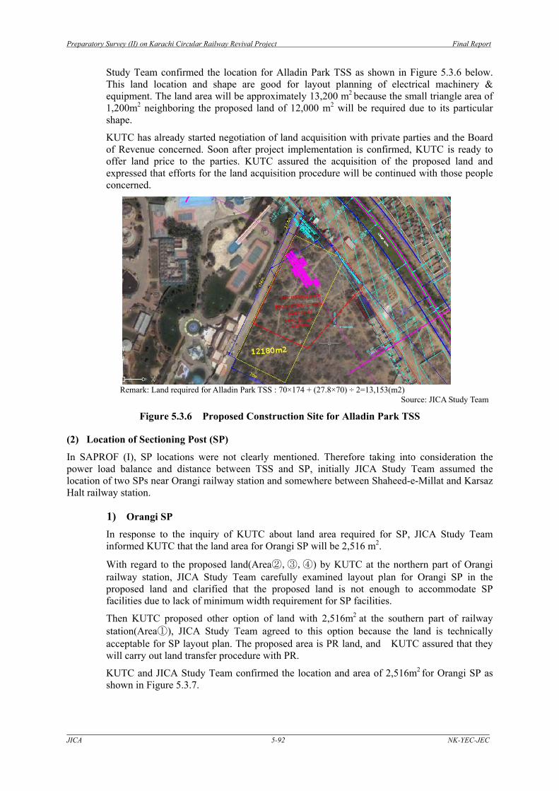
Study Team confirmed the location for Alladin Park TSS as shown in Figure 5.3.6 below. This land location and shape are good for layout planning of electrical machinery & equipment. The land area will be approximately 13,200 m2 because the small triangle area of 1,200m2 neighboring the proposed land of 12,000 m2 will be required due to its particular shape.
KUTC has already started negotiation of land acquisition with private parties and the Board of Revenue concerned. Soon after project implementation is confirmed, KUTC is ready to offer land price to the parties. KUTC assured the acquisition of the proposed land and expressed that efforts for the land acquisition procedure will be continued with those people concerned.
Remark: Land required for Alladin Park TSS : 70×174 + (27.8×70) ÷ 2=13,153(m2)
Source: JICA Study Team
Figure 5.3.6 Proposed Construction Site for Alladin Park TSS
(2) Location of Sectioning Post (SP)
In SAPROF (I), SP locations were not clearly mentioned. Therefore taking into consideration the power load balance and distance between TSS and SP, initially JICA Study Team assumed the location of two SPs near Orangi railway station and somewhere between Shaheed-e-Millat and Karsaz Halt railway station.
1) Orangi SP
In response to the inquiry of KUTC about land area required for SP, JICA Study Team informed KUTC that the land area for Orangi SP will be 2,516 m2.
With regard to the proposed land(Area②,③,④) by KUTC at the northern part of Orangi railway station, JICA Study Team carefully examined layout plan for Orangi SP in the proposed land and clarified that the proposed land is not enough to accommodate SP facilities due to lack of minimum width requirement for SP facilities.
Then KUTC proposed other option of land with 2,516m2 at the southern part of railway station(Area①), JICA Study Team agreed to this option because the land is technically acceptable for SP layout plan. The proposed area is PR land, and KUTC assured that they will carry out land transfer procedure with PR.
KUTC and JICA Study Team confirmed the location and area of 2,516m2 for Orangi SP as shown in Figure 5.3.7.

Preparatory Survey (II) on Karachi Circular Railway Revival Project Final Report
JICA 5-93 NK-YEC-JEC
① ② ③
③
④
②
①
④
Remark: Orangi SP: 37×68 = 2,516(m2)
Source: JICA Study Team
Figure 5.3.7 Proposed Construction Site for Orangi SP
2) Karsaz SP
KUTC and JICA Study Team confirmed that the land required for Karsaz SP is 2,516m2
same as Orangi SP.
Initially KUTC proposed three (3) SP locations between Shaheed-e-Millat and Karsaz Halt railway station. The option 1 is close to Shaheed-e-Millat, the option 2 is in the middle of two stations and the option 3 is close to Karsaz Halt station. JICA Study Team preferred the option 2 located in the middle of two railway stations considering the distance from TSS. However KUTC recommended option 3 with 2,516m2 owned by Karachi Water and Sewerage Board (KWSB) near Karsaz railway station.
The reason is because the option 2 is located at backside area of the offices and other facilities of KWSB and consequently KUTC will face the difficulty of securing the own access to SP without interference from KWSB during construction period and maintenance work in future.
As a result of technical examination, the option 3 was confirmed as possible location because the proposed land satisfies requirement for SP. Furthermore it is difficult to find out alternative land other than the option 3 because most land in this area is belonging to military forces.
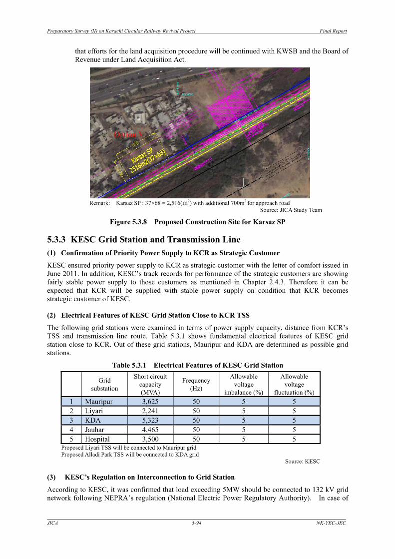
KUTC and JICA Study Team confirmed the location and area of 2,516m2 for Karsaz SP with additional 700m2 for approach road (Total area 3,216m2) as shown in Figure 5.3.8.
KUTC assured that they will purchase the KWSB’s land for Karsaz SP on the rates issued by Board of Revenue and construct new KWSB’s staff quarters currently existing on the land of the option 3. KWSB basically agreed land transfer subject to the undertaking by KUTC such as construction of staff quarters and land purchase mentioned above. KUTC also expressed
Preparatory Survey (II) on Karachi Circular Railway Revival Project Final Report
JICA 5-94 NK-YEC-JEC
that efforts for the land acquisition procedure will be continued with KWSB and the Board of Revenue under Land Acquisition Act.
Remark: Karsaz SP : 37×68 = 2,516(m2) with additional 700m2 for approach road
Source: JICA Study Team
Figure 5.3.8 Proposed Construction Site for Karsaz SP
5.3.3 KESC Grid Station and Transmission Line (1) Confirmation of Priority Power Supply to KCR as Strategic Customer
KESC ensured priority power supply to KCR as strategic customer with the letter of comfort issued in June 2011. In addition, KESC’s track records for performance of the strategic customers are showing fairly stable power supply to those customers as mentioned in Chapter 2.4.3. Therefore it can be expected that KCR will be supplied with stable power supply on condition that KCR becomes strategic customer of KESC.
(2) Electrical Features of KESC Grid Station Close to KCR TSS
The following grid stations were examined in terms of power supply capacity, distance from KCR’s TSS and transmission line route. Table 5.3.1 shows fundamental electrical features of KESC grid station close to KCR. Out of these grid stations, Mauripur and KDA are determined as possible grid stations.
Table 5.3.1 Electrical Features of KESC Grid Station Grid
substation
Short circuit capacity (MVA)
Frequency (Hz)
Allowable voltage
imbalance (%)
Allowable voltage
fluctuation (%) 1 Mauripur 3,625 50 5 5 2 Liyari 2,241 50 5 5 3 KDA 5,323 50 5 5 4 Jauhar 4,465 50 5 5 5 Hospital 3,500 50 5 5
Proposed Liyari TSS will be connected to Mauripur grid Proposed Alladi Park TSS will be connected to KDA grid
Source: KESC
(3) KESC’s Regulation on Interconnection to Grid Station
According to KESC, it was confirmed that load exceeding 5MW should be connected to 132 kV grid network following NEPRA’s regulation (National Electric Power Regulatory Authority). In case of
Option 3

Preparatory Survey (II) on Karachi Circular Railway Revival Project Final Report
JICA 5-95 NK-YEC-JEC
load exceeding 30 MW such as KCR, the consumer can choose 132 kV or 220 kV interconnections based on study result of selecting the best possible grid station. Due to less tripping on 220 kV circuit, the reliability of power supply from 220kV network increases more than 132kV one. However the cost of 220kV facilities is higher compared to 132 kV, therefore it is necessary to carefully examine the cost effectiveness. Procedure for new interconnection to KECS’s transmission network is that a formal application form should be submitted to KESC by KUTC with basic information such as KCR TSS location, load demand, desired voltage level etc. After the application is accepted by KESC, Project Development & Planning Department of KESC will review the contents of the application and the study on impact to the exiting grid network will be done by relevant department to determine best possible grid substation for power supply to KCR.
(4) KESC Transmission Network
Figure 5.3.9 shows location of grid stations & power plants and transmission network of KESC as of 23-09-2011.

Preparatory Survey (II) on Karachi C
ircular Railway Revival Project
Final Report
JIC
A 5-96
NK
-YEC-JEC
S
Figure 5.3.9 KESC Grid Station and Transmission Network (as of 23-09-2011) Source: KESC

Preparatory Survey (II) on Karachi Circular Railway Revival Project Final Report
JICA 5-97 NK-YEC-JEC
(5) Selection of Possible Grid Station
KESC grid stations have been examined in terms of reliability of power supply, construction cost of transmission line and land availability for the route.
To find out the possible grid station, KUTC and JICA Study Team informed KESC of the following information on interconnection to KESC grid station with provisional data such as KCR TSS location, receiving voltage and peak load based on traction power simulation data as follows.
1) In Case of N-A1
a) Total Load Demand for KCR Operation
i) Peak power load for train operation based on simulation 28,679 kW
ii) Safety factor 30% 28,679×30%= 8,604 kW
iii) KCR service power for such as railway stations facility, rolling stock depot, train operation control center, signaling and telecommunication facilities is assumed at 80% of 29,186kW.
28,679×80%= 22,943kW
Estimated maximum power load i)+ii)+iii) = 60,226kW ≒ 60MW
b) Proposed Location of KCR Substation Liyari and Alladin Park TSS
c) Receiving Voltage 220KV and 132kV
d) Approximate Commissioning Year Year of 2022
2) In Case of N-B1
a) Total Load Demand for KCR Operation
i) Peak power load for train operation based on simulation 29,674 kW
ii) Safety factor 30% 29,674×30% = 8,902 kW
iii) KCR service power for such as railway stations facility, rolling stock depot, train operation control center, signaling and telecommunication facilities is assumed at 80% of 29,186kW.
29,674× 80% = 23,739kW
Estimated maximum power load i)+ii)+iii) = 62,315kW ≒ 62MW
b) Proposed Location of KCR Substation Liyari TSS
c) Receiving Voltage 220KV
d) Approximate Commissioning Year Year of 2022
In response to the provisional information above given by KUTC, KESC recommended Mauripur and KDA grid stations as possible Grids stations that will meet the requirement of KCR power demand. These grid stations will be further examined by KESC and KUTC at design stage because power supply situation of KESC has been changing year by year.

Preparatory Survey (II) on Karachi Circular Railway Revival Project Final Report
JICA 5-98 NK-YEC-JEC
(6) Grid Station to Alladin Park TSS
Alladin Park TSS is proposed by KUTC. Alladin Park TSS’s location is close to KESC grid stations. Following three (3) KESC grid stations have been examined in terms of reliability of power supply, cost and land availability of transmission line. As a result, KDA grid station has been confirmed to be most suitable one out of following three grid stations.
1) Hospital Grid Station
The first option is KESC Hospital grid station. Since it is only around 1km from proposed Alladin Park TSS, it is considered to be the first priority taking the construction cost into account. However, it was found that there exists only single circuit of 132 kV from Jauhar grid station to Hospital grid station, accordingly the reliability of power supply will be very low due to limited capacity.
In addition, Hospital grid is located in densely populated area and load demand in this area will increase rapidly in future. Therefore it cannot be expected that Hospital grid will supply stable power to KCR unless KESC strengthens the power supply capacity of Hospital grid in near future.
2) Jauhar Grid Station
The second option is KESC Jauhar grid station which is about 4kM from Alladin Park TSS. Findings are that construction cost of transmission line is not expensive because of distance to Alladin Park TSS, however KESC’s temporary technical examination shows that Jauhar grid is not suitable because of its limited capacity to meet a big load demand for KCR train operation. Currently Jauhar grid capacity cannot handle further 100MW load demand. According to KESC, if 100MW demand is reflected on the line, it will result in overloading for the circuit.
3) KDA Grid Station
The third option is KDA grid station which is about 12kM from Alladin Park TSS. According to KESC’s temporary technical examination on the reliable power supply as stated in Figure 5.3.10 below, KDA grid is most suitable one although construction cost for transmission line will be much higher than other grids stations. In case of N-A1, KESC recommends that Alladin Park TSS should be connected to KDA grid station due to KCR’s huge load demand.
In case of N-B1, KESC recommends that small scale TSS of 3MW at Alladin Park should be connected to Hospital Grid.

Preparatory Survey (II) on Karachi Circular Railway Revival Project Final Report
JICA 5-99 NK-YEC-JEC
Source: JICA Study Team
Figure 5.3.10 KESC’s Notice of KDA Grid Station for KCR Power Supply

Preparatory Survey (II) on Karachi Circular Railway Revival Project Final Report
JICA 5-100 NK-YEC-JEC
(7) Grid Station to Liyari TSS
Liyari TSS was proposed as possible location of TSS. Three (3) KESC grid stations below have been examined in terms of reliability of power supply, cost and land availability of transmission line. As a result, Mauripur grid station has been confirmed to be most suitable one to supply power to Liyari TSS.
1) Mauripur Grid Station
The first option is KESC Mauripur grid station which is only around 0.8km from Liyari TSS. According to KESC’s temporary technical examination, Mauripur grid is suitable due to high reliability of stable power supply to KCR train operation, therefore Mauripur grid is considered to be the priority.
Figure 5.3.11 and Figure 5.3.12 show typical schematic diagram of 132kV and 220 kV circuit of Mauripur grid station.
2) Liyari Grid Station
Second option is KESC Liyari grid station which is about 1km from Liyari TSS. It was clarified that construction cost of transmission line is acceptable because of its distance to TSS however Liyari grid station is not suitable because of its small capacity to supply huge load demand for KCR train operation.
3) KESC PLDP (Power Line Drop Point) between Mauripur Grid and Lalazar Grid Station
There exists PLDP of 220 kV double circuits between Mauripur and Lalazar grid station. According to KESC it is possible to technically connect the transmission line to PLDP, however in accordance with KESC’s regulation, connecting at PLDP is not allowed because of safety reason.

Preparatory Survey (II) on Karachi Circular Railway Revival Project Final Report
JICA 5-101 NK-YEC-JEC
Source: KESC
Figure 5.3.11 Schematic Diagram of 132kV Circuit of Mauripur Grid Station

Preparatory Survey (II) on Karachi Circular Railway Revival Project Final Report
JICA 5-102 NK-YEC-JEC
Source: KESC
Figure 5.3.12 Schematic Diagram of 220kV Circuit of Mauripur Grid Station Transmission Line from KESC Grid Station

Preparatory Survey (II) on Karachi Circular Railway Revival Project Final Report
JICA 5-103 NK-YEC-JEC
4) Transmission Line Route between AlladinPark & Liyari TSS and KESC Grid Station
To find out possible transmission route from KDA grid substation to Alladin Park TSS and Mauripur grid station to Liyari TSS, site survey was conducted by KUTC and JICA Study Team. Either cable or overhead wire case was examined based on the land availability of the transmission line route.
JICA Study Team proposed tentative transmission route of KDA grid substation to Alladin Park TSS as shown in Figure 5.3.13. While Transmission route between Liyari TSS and Mauriopur grid is shown in Figure 5.3.5.
Alladin Park TSS will be connected to KDA grid with 132kV transmission line of about 12.5kM and Liyari TSS will be connected to Mauripur grid with 220kV transmission line of about 0.8kM. These transmission routes should be further reviewed at design stage based on more detailed route survey.
Designing of transmission line should be conducted in accordance with KESC’s technical requirement. Underground cable or overhead wire will be used for transmission line depending on the transmission route. Whole cost of transmission line will be borne by KUTC.
Acquiring Right of Way and work permit for the entire transmission route before implementation of construction work is the responsibility of KUTC.
S1
Alladin Park TSS
S2
S3
S4
S5
S6S7S8
S9
S10
S11S12
S13S14
S17
S15
S19
S16
S18HOSPITAL-GS
S20
Source: JICA Study Team
Figure 5.3.13 Transmission Line Route between KDA Grid and Alladin Park TSS
5) Responsibility of Construction & Maintenance of Transmission Line and Switching Facility
・ All the cost required for transmission line will be borne by KUTC ・ Transmission line maintenance is responsibility of KUTC and normally maintenance
work will be conducted by KESC or third party based on the maintenance agreement with KUTC and KESC.
・ Switching facility is constructed in KESC grid station by KUTC in accordance with

Preparatory Survey (II) on Karachi Circular Railway Revival Project Final Report
JICA 5-104 NK-YEC-JEC
KESC’s specification and will be handed over to KESC together with spare parts after completion of construction work and be registered as asset of KESC.
・ Boundary of asset is sealing end in grid station where transmission line is connected to switching facility. Responsibility of construction and maintenance work is summarized as Table 5.3.2.
Table 5.3.2 Responsibility of Construction and Maintenance Work Item Transmission Line Switching Facility
Construction KUTC KUTC Spare Parts KUTC KUTC
Asset KUTC KESC O&M implementation KESC or third party by contract KESC
Source: JICA Study Team
5.3.4 Power Load Simulation (1) Purpose of Simulation
In order to design correctly power supply facility of KCR with AT feeding system and to examine effects & value of regenerative power of KCR, traction power load simulation was conducted by using basic data of electric car specifications, route alignment and train operation plan that will be introduced to KCR.
(2) Summary of Simulation Results
1) Conditions ・ Time Duration of Simulation : Two hours between 7:00 – 9:00 at peak hour (N-A1)
One hour between 7:00–8:00 at peak hour (N-B1) ・ Number of electric car : 4 cars (2M2T) and 8cars (4M4T) for 1 train set ・ Train operation diagram: Year 2051 (Maximum Load Condition) ・ Locations of traction substation (TSS): Liyari TSS and Alladin Park TSS
2) Salient Features of Power Consumption, Regenerative Effect and Back-up System
Simulation was conducted with 2051 train operation diagram of maximum load condition. Peak Load in 2022 opening year is assumed at approximately 40% of peak load in 2051 and Power Consumption in 2022 opening year is assumed at approximately 50% of power consumption in 2051 as shown in Table 5.3.3.
Peak Load (MW) and Power Consumption (MWh) in 2051 are shown in Table 5.3.4. In terms of regenerative effect, Peak Load (MW) and Power Consumption (MWh) saved by regenerative system in 2051 are also shown in Table 5.3.4.
Table 5.3.5 shows Back-up Power Supply Facility for emergency situation of Liyari TSS in case of N-B1. Required power supply capacity of small-scale TSS is assumed at 3MVA.
Table 5.3.3 Peak Load and Power Consumption in 2022 (Opening Year) Train Operation in 2022 (Opening Year)
Option N-A1 N-B1
Traction Substation (TSS) 2 TSS (Lyari TSS& Alladin Park TSS)
1 TSS (Lyari TSS)
Estimated Peak Load (MW) for the Entire Section in Case of
Single TSS Operation 26MW 26MW
Total Power Consumption (MWh) 18MWh 13MWh Source: JICA Study Team

Preparatory Survey (II) on Karachi Circular Railway Revival Project Final Report
JICA 5-105 NK-YEC-JEC
Table 5.3.4 Peak Load and Power Consumption in 2051 Train Operation in 2051
Option N-A1 N-B1
Traction Substation 2 TSS
(Lyari TSS& Alladin Park TSS)
1TSS (Lyari TSS)
Peak Load (MW)
Peak Load for the Entire Section in Case of Single TSS Operation 60MW 62MW
Peak Load Saved by Regenerative System 9.7MW 5.9MW
Power Consumption
(MWh)
Total Power Consumption/h 36MWh 26MWh Power Consumption/h Saved
by Regenerative System 11MWh 7MWh
Source: JICA Study Team
Table 5.3.5 Back-up Power Supply Facility in N-B1
Location Purpose Feeding System Assumed Power Supply Capacity
Alladin Park TSS
(1)In case of power outage in Liyari TSS To move stopped trains to the nearest stations safely and quickly. (2)In case of normal operation To provide traction power for train operation between Drigh Road and Depot Hill stabling yard.
AC 25kV Simple Feeding System 3MVA
Source: JICA Study Team 3) Peak Load, Voltage Fluctuation and Unbalance Rate
a) Normal Train Operation by double TSSs (N-A1) Permissible voltage fluctuation and unbalance rate is 5%.
Table 5.3.6 Alladin Park TSS 1 Peak power load 15,439 kW (07:01:00) 2 Maximum voltage fluctuation rate Vrs:0.17%, Vst:0.22% , Vtr:0.10% 3 Maximum voltage unbalance rate 0.18% 4 Minimum receiving voltage 131.7 kV
Source: JICA Study Team
Table 5.3.7 Liyari TSS 1 Peak power load 22,874 kW (07:00:06) 2 Maximum voltage fluctuation rate Vrs:0.47%, Vst:0.72% , Vtr:0.12% 3 Maximum voltage unbalance rate 0.59% 4 Minimum receiving voltage 218.4 kV
Source: JICA Study Team
b) Extended Feeding by Single TSS(N-A1)
Table 5.3.8 Alladin Park TSS without Liyari TSS 1 Peak power load 28,553kW (07:08:06) 2 Maximum voltage fluctuation rate Vrs:0.37%, Vst:0.53% , Vtr:0.16% 3 Maximum voltage unbalance rate 0.42% 4 Minimum receiving voltage 131.3kV
Source: JICA Study Team
Preparatory Survey (II) on Karachi Circular Railway Revival Project Final Report
JICA 5-106 NK-YEC-JEC
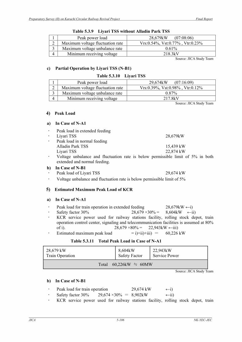
Table 5.3.9 Liyari TSS without Alladin Park TSS 1 Peak power load 28,679kW (07:08:06) 2 Maximum voltage fluctuation rate Vrs:0.54%, Vst:0.77% , Vtr:0.23% 3 Maximum voltage unbalance rate 0.61% 4 Minimum receiving voltage 218.3kV
Source: JICA Study Team
c) Partial Operation by Liyari TSS (N-B1)
Table 5.3.10 Liyari TSS 1 Peak power load 29,674kW (07:16:09) 2 Maximum voltage fluctuation rate Vrs:0.39%, Vst:0.98% , Vtr:0.12% 3 Maximum voltage unbalance rate 0.87% 4 Minimum receiving voltage 217.8kV
Source: JICA Study Team
4) Peak Load
a) In Case of N-A1
Peak load in extended feeding Liyari TSS 28,679kW Peak load in normal feeding
Alladin Park TSS 15,439 kW Liyari TSS 22,874 kW
Voltage unbalance and fluctuation rate is below permissible limit of 5% in both extended and normal feeding.
b) In Case of N-B1 Peak load of Liyari TSS 29,674 kW Voltage unbalance and fluctuation rate is below permissible limit of 5%
5) Estimated Maximum Peak Load of KCR
a) In Case of N-A1
Peak load for train operation in extended feeding 28,679kW ←i) Safety factor 30% 28,679 ×30% = 8,604kW ←ii) KCR service power used for railway stations facility, rolling stock depot, train
operation control center, signaling and telecommunication facilities is assumed at 80% of i). 28,679 ×80% = 22,943kW ←iii)
Estimated maximum peak load = i)+ii)+iii) = 60,226 kW
Table 5.3.11 Total Peak Load in Case of N-A1
28,679 kW Train Operation
8,604kW Safety Factor
22,943kW Service Power
Total 60,226kW ≒ 60MW Source: JICA Study Team
b) In Case of N-B1
Peak load for train operation 29,674 kW ←i) Safety factor 30% 29,674 ×30% = 8,902kW ←ii) KCR service power used for railway stations facility, rolling stock depot, train

Preparatory Survey (II) on Karachi Circular Railway Revival Project Final Report
JICA 5-107 NK-YEC-JEC
operation control center, signaling and telecommunication facilities is assumed at 80% of i). 29,674 ×80% = 23,739kW ←iii) Estimated maximum power load = i)+ii)+iii) =62,315 kW
Table 5.3.12 Total Peak Load in Case of N-B1
29,674 kW Train Operation
8,902kW Safety Factor
23,739kW Service Power
Total 62,315kW ≒ 62MW Source: JICA Study Team
6) Effect of Regenerative System
a) N-A1 Normal Feeding
i) Electric Power Consumption(kWh) saved by regeneration system in normal feeding .
Electric Power Consumption(kWh) saved by regeneration system is shown in Table 5.3.13(Alladin Park TSS) and Table 5.3.14(Liyari TSS) respectively.
Alladin Park TSS: 6,493kWh, Efficiency 36.6% Liyari TSS: 14,454kWh, Efficiency 42.5%
ii) Peak Load(kW) saved by regeneration system in normal feeding .
Peak Load(kW) saved by regeneration system is shown in Table 5.3.13(Alladin Park TSS) and Table 5.3.14(Liyari TSS) respectively.
Alladin Park TSS: 1,428kW, Efficiency 8.5% Liyari TSS: 3,994kW, Efficiency 14.9%
Table 5.3.13 Regenerative Effect of Alladin Park TSS (N-A1) (Normal Feeding)
efficiencyoff on (%)
Max Effective Power(kW) 9105.9 8847 258.9 -Max Reactive Power(kVar) 1925.6 2436.5 -510.9 -Electric Power Consumption(kWh) 8783.2 5853.8 2929.4 33.4Average Power Factor 0.98 0.93 0.0 -Max Effective Power(kW) 10258.9 7329.7 2929.2 -Max Reactive Power(kVar) 2146.4 2643.3 -496.9 -Electric Power Consumption(kWh) 8967.8 5403.6 3564.2 39.7Average Power Factor 0.98 0.91 0.1 -
Incoming Max Effective Power(kW) 16867.0 15439.0 1428.0 8.5Bus Electric Power Consumption(kWh) 17751.0 11257.4 6493.6 36.6
TeaserFeedingBus
substationregenerative brake
difference
MainFeedingBus
ALLADIN PARK SSItem
Note: Efficiency=Difference / Regenerative Brake Off Source: JICA Study Team
Preparatory Survey (II) on Karachi Circular Railway Revival Project Final Report
JICA 5-108 NK-YEC-JEC
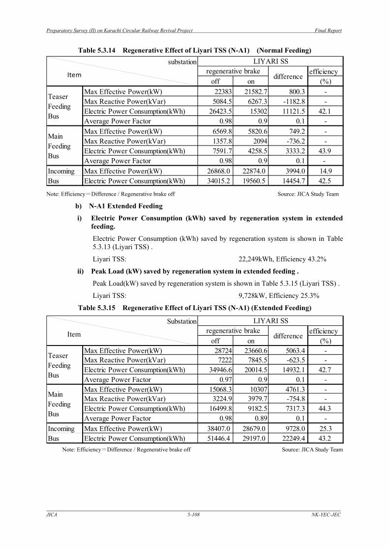
Table 5.3.14 Regenerative Effect of Liyari TSS (N-A1) (Normal Feeding)
efficiencyoff on (%)
Max Effective Power(kW) 22383 21582.7 800.3 -Max Reactive Power(kVar) 5084.5 6267.3 -1182.8 -Electric Power Consumption(kWh) 26423.5 15302 11121.5 42.1Average Power Factor 0.98 0.9 0.1 -Max Effective Power(kW) 6569.8 5820.6 749.2 -Max Reactive Power(kVar) 1357.8 2094 -736.2 -Electric Power Consumption(kWh) 7591.7 4258.5 3333.2 43.9Average Power Factor 0.98 0.9 0.1 -
Incoming Max Effective Power(kW) 26868.0 22874.0 3994.0 14.9Bus Electric Power Consumption(kWh) 34015.2 19560.5 14454.7 42.5
MainFeedingBus
substationregenerative brake
difference
TeaserFeedingBus
LIYARI SS
Item
Note: Efficiency=Difference / Regenerative brake off Source: JICA Study Team
b) N-A1 Extended Feeding
i) Electric Power Consumption (kWh) saved by regeneration system in extended feeding.
Electric Power Consumption (kWh) saved by regeneration system is shown in Table 5.3.13 (Liyari TSS) .
Liyari TSS: 22,249kWh, Efficiency 43.2%
ii) Peak Load (kW) saved by regeneration system in extended feeding .
Peak Load(kW) saved by regeneration system is shown in Table 5.3.15 (Liyari TSS) .
Liyari TSS: 9,728kW, Efficiency 25.3%
Table 5.3.15 Regenerative Effect of Liyari TSS (N-A1) (Extended Feeding)
efficiencyoff on (%)
Max Effective Power(kW) 28724 23660.6 5063.4 -Max Reactive Power(kVar) 7222 7845.5 -623.5 -Electric Power Consumption(kWh) 34946.6 20014.5 14932.1 42.7Average Power Factor 0.97 0.9 0.1 -Max Effective Power(kW) 15068.3 10307 4761.3 -Max Reactive Power(kVar) 3224.9 3979.7 -754.8 -Electric Power Consumption(kWh) 16499.8 9182.5 7317.3 44.3Average Power Factor 0.98 0.89 0.1 -
Incoming Max Effective Power(kW) 38407.0 28679.0 9728.0 25.3Bus Electric Power Consumption(kWh) 51446.4 29197.0 22249.4 43.2
LIYARI SS
MainFeedingBus
Substationregenerative brake
difference
TeaserFeedingBus
Item
Note: Efficiency=Difference / Regenerative brake off Source: JICA Study Team

Preparatory Survey (II) on Karachi Circular Railway Revival Project Final Report
JICA 5-109 NK-YEC-JEC
c) N-B1 Feeding (Drigh Road to Shah Abdul Latif)
i) Electric Power Consumption (kWh) saved by regeneration system in N-B1.
Electric Power Consumption (kWh) saved by regeneration system is shown in Table 5.3.16 (Liyari TSS).
Liyari TSS: 6,942kWh,Efficiency 38.6%
ii) Peak Load (kW) saved by regeneration system in N-B1.
Peak Load (kW) saved by regeneration system is shown in Table 5.3.16 (Liyari TSS). Liyari TSS: 5,927kW, Efficiency 16.6%
Table 5.3.16 Regenerative Effect of Liyari TSS (N-B1, Drigh Road – Shah Abdul Latif )
efficiencyoff on (%)
Max Effective Power(kW) 26236.6 26236.6 0.0 -Max Reactive Power(kVar) 6016.5 7758 -1741.5 -Electric Power Consumption(kWh) 15704.6 8989.3 6715.3 42.8Average Power Factor 0.98 0.9 0.1 -Max Effective Power(kW) 9736 9736 0.0 -Max Reactive Power(kVar) 2017.4 2075.9 -58.5 -Electric Power Consumption(kWh) 2280.6 2053.3 227.3 10.0Average Power Factor 0.98 0.96 0.0 -
Incoming Max Effective Power(kW) 35602.0 29675.0 5927.0 16.6Bus Electric Power Consumption(kWh) 17985.2 11042.6 6942.6 38.6
TeaserFeedingBus
LIYARI SS
MainFeedingBus
substationregenerative brake
differenceItem
Note: Efficiency=Difference / Regenerative brake off Source: JICA Study Team
(3) Conditions of Simulation
1) Basic Data and Condition Used for Traction Power Load Simulation
a) Traction Current of Electric Car:
Table 5.3.17 Traction Current of Electric Car 4cars (2M2T) 8cars (4M4T)
Peak traction current 102A Power factor 0.98
204A Power factor 0.98
Auxiliary machine current 7.2 A 14.4A
Regenerative current 116A Power factor 0.98
232A Power factor 0.98
Source: JICA Study Team b) Train Diagram
Table 5.3.18 Circular Line and Extension Line (N-A1) Circular line with extension line
Year Formation of Train Set Train Diagram
2051
4-car (2M2T) for circular line
2M2T: 15trains/hour (4Minutes Headway),
8-car (4M4T) for extension line
4M4T: 7.5trains/hour (8Minutes Headway)
Source: JICA Study Team
Preparatory Survey (II) on Karachi Circular Railway Revival Project Final Report
JICA 5-110 NK-YEC-JEC
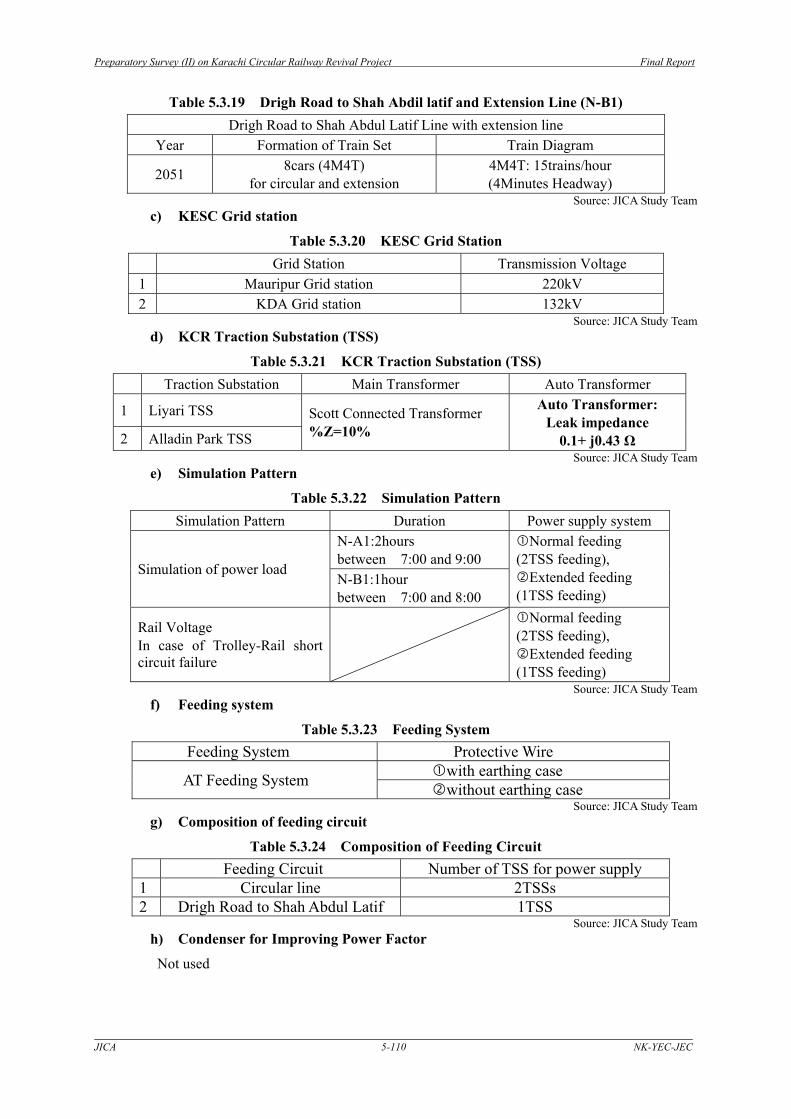
Table 5.3.19 Drigh Road to Shah Abdil latif and Extension Line (N-B1) Drigh Road to Shah Abdul Latif Line with extension line
Year Formation of Train Set Train Diagram
2051 8cars (4M4T) for circular and extension
4M4T: 15trains/hour (4Minutes Headway)
Source: JICA Study Team c) KESC Grid station
Table 5.3.20 KESC Grid Station Grid Station Transmission Voltage
1 Mauripur Grid station 220kV 2 KDA Grid station 132kV
Source: JICA Study Team d) KCR Traction Substation (TSS)
Table 5.3.21 KCR Traction Substation (TSS) Traction Substation Main Transformer Auto Transformer
1 Liyari TSS Scott Connected Transformer %Z=10%
Auto Transformer: Leak impedance
0.1+ j0.43 Ω 2 Alladin Park TSS Source: JICA Study Team
e) Simulation Pattern
Table 5.3.22 Simulation Pattern Simulation Pattern Duration Power supply system
Simulation of power load
N-A1:2hours between 7:00 and 9:00
Normal feeding (2TSS feeding),
Extended feeding (1TSS feeding)
N-B1:1hour between 7:00 and 8:00
Rail Voltage In case of Trolley-Rail short circuit failure
Normal feeding (2TSS feeding),
Extended feeding (1TSS feeding)
Source: JICA Study Team f) Feeding system
Table 5.3.23 Feeding System Feeding System Protective Wire
AT Feeding System with earthing case without earthing case
Source: JICA Study Team g) Composition of feeding circuit
Table 5.3.24 Composition of Feeding Circuit Feeding Circuit Number of TSS for power supply
1 Circular line 2TSSs 2 Drigh Road to Shah Abdul Latif 1TSS
Source: JICA Study Team h) Condenser for Improving Power Factor
Not used

Preparatory Survey (II) on Karachi Circular Railway Revival Project Final Report
JICA 5-111 NK-YEC-JEC
i) Feeding Voltage
Feeding voltage at TSS : 55kV (Feeder and Trolley) Standard voltage at Pantograph : 25kV, Max. voltage 27.5kV, Min. voltage 20kV
j) Impedance Used for Simulation
Table 5.3.25 Impedance (55kV Level)
Source: JICA Study Team
2) Overhead Contact Equipment Layout
Design of overhead catenary system in viaduct section used in power simulation is shown in Figure 5.3.14. Feature of each catenary system is shown in Table 5.3.26.
1.01
3.25 2.02
1.71
0.85
5.955.10
3.70 3.85
8.00
M2
T2
GL
T1
M1
F1 F2
R1 R2
PW2
center point
1.435
unit:m
PW1
Source: JICA Study Team
Figure 5.3.14 Overhead Contact Equipment Layout in Viaduct Section
TSS
Receiving Voltage
Short Circuit Capacity Feeding Transformer Total Impedance
kV MVA Capacity MVA %Z Impedance Ω
Liyari 220 3,625 50 10 0.303+j6.05 0.332+j7.719 Alladin Park 132 5,323 50 10 0.303+j6.05 0.327+j7.405

Preparatory Survey (II) on Karachi Circular Railway Revival Project Final Report
JICA 5-112 NK-YEC-JEC
Table 5.3.26 Feature of Catenary System in Viaduct Section
distance
from center
point point
height from
the ground
level
radius of
conductorsag
specific
resistivity
relative
permeabilitygauge
X(m) heightY(m) r(m) d(m) Ri(Ω/km) μS (m)
M1 PH 150 mm2 -1.85 13.95 0.008 0.38 0.1880 1.0 -
M2 PH 150 mm2 1.85 13.95 0.008 0.38 0.1880 1.0 -
T1 PHC 110 mm2 -1.85 13.10 0.00617 - 0.2042 1.0 -
T2 PHC 110 mm2 1.85 13.10 0.00617 - 0.2042 1.0 -
F1 PH 100 mm2 -3.87 15.66 0.008 1.10 0.1880 1.0 -
F2 PH 100 mm2 3.87 15.66 0.008 1.10 0.1880 1.0 -
PW1 H 38 mm2 -5.10 16.67 0.0039 0.92 0.4840 1.0 -
PW2 H 38 mm2 5.10 16.67 0.0039 0.92 0.4840 1.0 -
R1 60 kg -1.85 8.00 0.105 70 1.435
R2 60 kg 1.85 8.00 0.105 70 1.435
feeder conductor
Kind of wire
0.1152 + j0.1237 Ω/km
0.1152 + j0.1237 Ω/km
Protective wire
rail
messenger wire
contact line
Source: JICA Study Team
3) Calculation Method
a) Voltage Fluctuation and Unbalance Rate for Scott Connected Transformer
Scott connected transformer composition is shown in Figure 5.3.15
.
220kV
55kV T phase
M phase
T
R
F
T R F
- IT
Iv
Iu
Iw
Vuv
Vwu
Vvw
U
V
W
27.5kV
AT
23√
Source: JICA Study Team
Figure 5.3.15 Scott- Connected Transformer Composition
Formula on receiving voltage fluctuation is shown in formula (1).

Preparatory Survey (II) on Karachi Circular Railway Revival Project Final Report
JICA 5-113 NK-YEC-JEC
⎪⎪⎪⎪
⎭
⎪⎪⎪⎪
⎬
⎫
×⎟⎠⎞
⎜⎝⎛ π
+γ−θ=Δ
×⎭⎬⎫
⎩⎨⎧
⎟⎠⎞
⎜⎝⎛ π
+γ−θ+⎟⎠⎞
⎜⎝⎛ π
−γ−θ−=Δ
×⎭⎬⎫
⎩⎨⎧
⎟⎠⎞
⎜⎝⎛ π
−γ−θ−⎟⎠⎞
⎜⎝⎛ π
+γ−θ=Δ
%sinSP
V
%sinSsinSP
V
%sinSsinSP
V
MMS
WU
MMTTS
VW
MMTTS
UV
1002
21
10063
31
10063
31
----------- (1)
(%)100100100S
2
S
220 ×=××
=××
=PW
PIV
VIXk
Voltage unbalance rate k is shown in following formula.
Where,
SM, ST : apparent power seen from substation θM, θT : load power factor angle seen from substation γ : transmitting line impedance angle k : voltage unbalance rate PS : power source short-circuit capacity X0 : power source impedance I2 : negative-phase-sequence current W2 : negative-phase-sequence power
And each three phase current is calculated by formula (2).
⎪⎪⎪⎪
⎭
⎪⎪⎪⎪
⎬
⎫
⎟⎠⎞
⎜⎝⎛ θ−θ+π
×××+⎭⎬⎫
⎩⎨⎧
+=
×=
⎟⎠⎞
⎜⎝⎛ θ−θ+π
×××+⎭⎬⎫
⎩⎨⎧
+=
TMT
MT
MW
TV
TMT
MT
Mu
cosI
II
II
II
cosI
II
II
232
3
32
232
3
22
22
------------------------- (2)
Formula on receiving voltage fluctuation is shown in formula (3).
( )
(%)100)65sin(
P)
32sin(
PV
(%)1002
sin(P
2)32sin(
PV
(%)100)6
sin(P
sinP
2V
S
T
S
MVW
S
T
S
MUV
S
T
S
MWU
×π+γ−θ+π
+γ−θ−=Δ
×⎟⎠⎞π−γ−θ×−π−γ−θ−=Δ
×π
+−θ+γ−θ×=Δ
TM
TM
TM
SS
SS
SSγ
-- (3)
Voltage unbalance rate kv is shown in following formula.
( )%IIIIPVk TMTM
SV 10022 ×−+=
And each three phase currents are calculated by formula (4).

Preparatory Survey (II) on Karachi Circular Railway Revival Project Final Report
JICA 5-114 NK-YEC-JEC
( )( )MMMW
TTTV
TMWVWVu
sinjcosIIsinjcosII
)cos(IIIII
θ+θ=θ+θ=
θ−θ+π
++=3
222
--------------------(4)
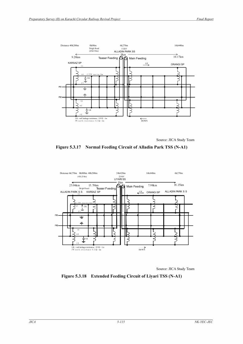
b) Feeding Circuit of Electric Power Supply for Circular Line (N-A1)
Normal Feeding circuit of Liyari TSS and Alladin Park TSS used for simulation is shown in Figure 5.3.16 and Figure 5.3.17 respectively and Extended Feeding circuit is shown in Figure 5.3.18 and Figure 5.3.19.
15.78km
T1
R1
F1
T2
R2
F2
LK
LK
0km7.98km
PW1
PW2
LIYARI SS
KARSAZ SP ORANGI SP
Distance 16k440m 24k420m 40k200m220kV
Main Feeding Teaser Feeding
UP
DOWNLK::rail leakage resistance 100Ω・km
PW:earth resistance 0.5Ω・km
CPW spacing 2km
Source: JICA Study Team
Figure 5.3.16 Normal Feeding Circuit of Liyari TSS (N-A1)
Preparatory Survey (II) on Karachi Circular Railway Revival Project Final Report
JICA 5-115 NK-YEC-JEC
10.17km
T1
R1
F1
T2
R2
F2
LK
LK
LK::rail leakage resistance 100Ω・km
PW:earth resistance 0.5Ω・km
0km9.28km
CPW spacing 2km
PW1
PW2
ALLADIN PARK SS
Teaser Feeding Main Feeding
ORANGI SP KARSAZ SP
Distance 40k200m 0k00m 6k270m 16k440mDrigh Road 132kV(43k210m)
DOWN
UP
Source: JICA Study Team
Figure 5.3.17 Normal Feeding Circuit of Alladin Park TSS (N-A1)
7.98km
T1
R1
F1
T2
R2
F2
LK
LK
0km15.78km
PW1
PW2
ORANGI SP KARSAZ SP
Distance 6k270m 0k000m 40k200m 24k420m 16k440m 6k270m220kV
18.15km25.06km
LIYARI SS
ALLADIN PARK S S ALLADIN PARK S S Drigh R oa d
(43k210m)
Main FeedingTeaser Feeding
UP
DOWNLK:: rail lea kage resi st ance 100Ω・kmPW:earth resistance 0.5Ω・km
CPW sp acin g 2k m
Source: JICA Study Team
Figure 5.3.18 Extended Feeding Circuit of Liyari TSS (N-A1)

Preparatory Survey (II) on Karachi Circular Railway Revival Project Final Report
JICA 5-116 NK-YEC-JEC
10.17km
T1
R1
F1
T2
R2
F2
LK
LK
0km9.28km
PW1
PW2
ALLADIN PARKSS
ORANGI SP LIYARI SS
Distance 24k420m 40k200m 0k000m 6k270m 16k440m 24k420m
132kV
18.15km25.06km
KARSAZ SP LIYARI SS Drigh Road
(43k210m)
Main FeedingTeaser Feeding
UP
DOWNLK::rail leakage resistance 100Ω・km
PW:earth resistance 0.5Ω・km
CPW spacing 2km
Source: JICA Study Team
Figure 5.3.19 Extended Feeding Circuit of Alladin Park TSS (N-A1)
c) Feeding Circuit of Liyari TSS for Drigh Road - Shah Abdul Latif Line (N-B1)
Source: JICA Study Team
Figure 5.3.20 Feeding Circuit of Liyari TSS (N-B1)
4) Current and Power Consumption of Electric Car
a) Characteristics of 1 train set of 4 cars are described as below.
Weight: 205Ton (2M2T), Maximum speed:110km,
Maximum traction force : 190kN,
Maximum current :102A (Without auxiliary current),Power factor:0.98
Maximum Brake force:239kN (Regenerative brake)
Maximum Regenerative current: 116A (Without auxiliary current)
Preparatory Survey (II) on Karachi Circular Railway Revival Project Final Report
JICA 5-117 NK-YEC-JEC
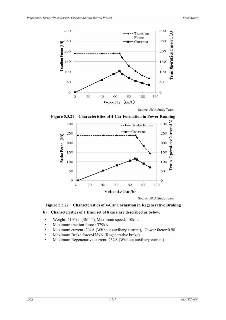
Source: JICA Study Team
Figure 5.3.21 Characteristics of 4-Car Formation in Power Running
Source: JICA Study Team
Figure 5.3.22 Characteristics of 4-Car Formation in Regenerative Braking
b) Characteristics of 1 train set of 8 cars are described as below.
Weight: 410Ton (4M4T), Maximum speed:110km, Maximum traction force : 379kN, Maximum current :204A (Without auxiliary current),Power factor:0.98 Maximum Brake force:478kN (Regenerative brake) Maximum Regenerative current: 232A (Without auxiliary current)

Preparatory Survey (II) on Karachi Circular Railway Revival Project Final Report
JICA 5-118 NK-YEC-JEC
Source: JICA Study Team
Figure 5.3.23 Characteristics of 8-Car Formation in Power Running
Source: JICA Study Team
Figure 5.3.24 Characteristics of 8-Car Formation in Regenerative Running
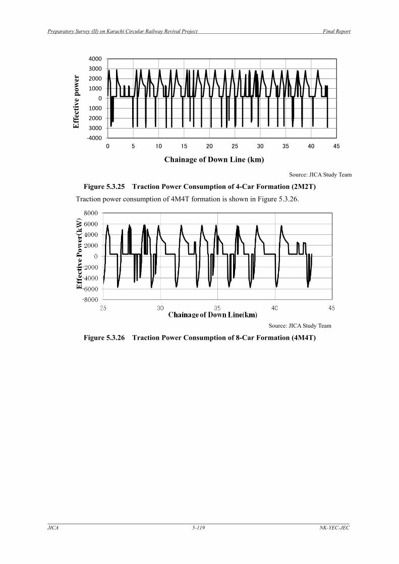
c) Traction Power Consumption
Traction power consumption of 2M2T formation is shown in Figure 5.3.25.
Preparatory Survey (II) on Karachi Circular Railway Revival Project Final Report
JICA 5-119 NK-YEC-JEC
‐4000
‐3000
‐2000
‐1000
0
1000
2000
3000
4000
0 5 10 15 20 25 30 35 40 45
有効
電力(kW)
キロ程(km)
Source: JICA Study Team
Figure 5.3.25 Traction Power Consumption of 4-Car Formation (2M2T)
Traction power consumption of 4M4T formation is shown in Figure 5.3.26.
Source: JICA Study Team
Figure 5.3.26 Traction Power Consumption of 8-Car Formation (4M4T)
Eff
ectiv
e po
wer
Chainage of Down Line (km)
Preparatory Survey (II) on Karachi Circular Railway Revival Project Final Report
JICA 5-120 NK-YEC-JEC
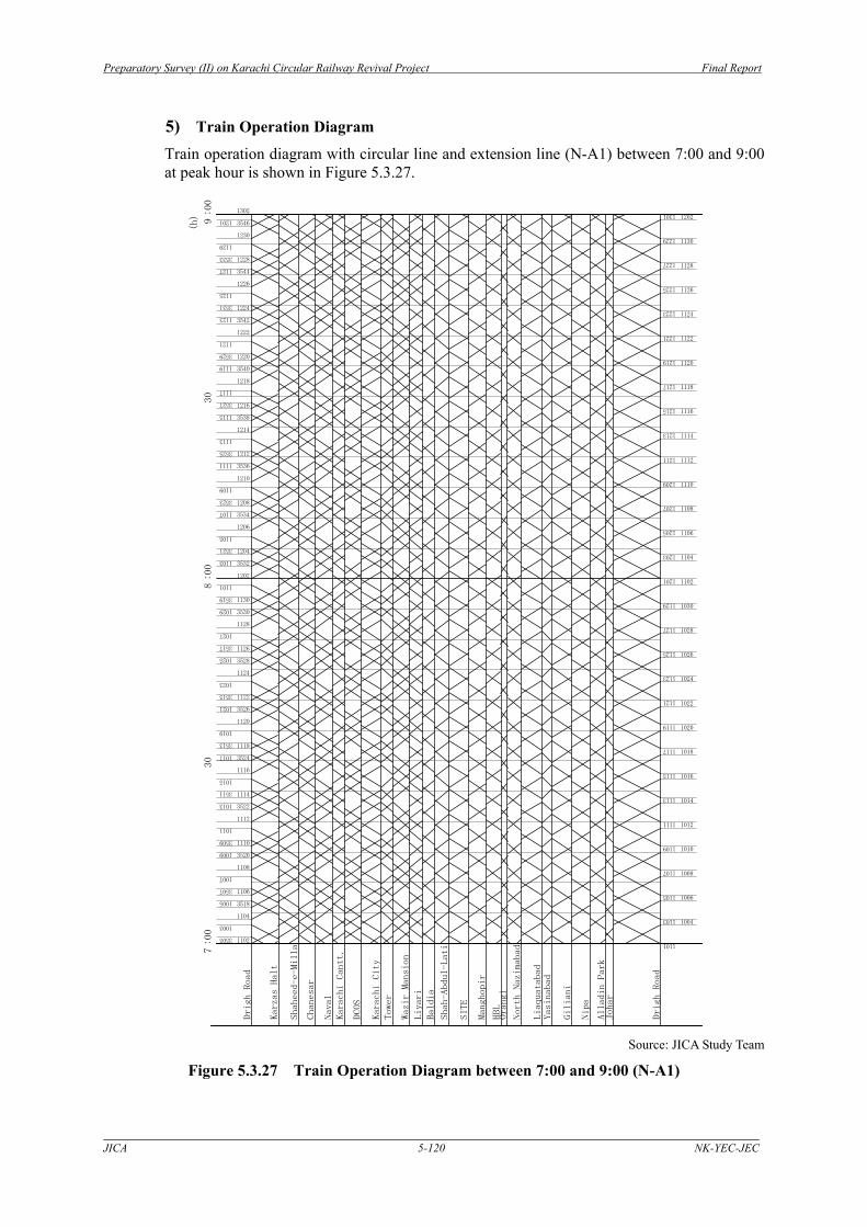
5) Train Operation Diagram
Train operation diagram with circular line and extension line (N-A1) between 7:00 and 9:00 at peak hour is shown in Figure 5.3.27.
7:00
30
8:00
30
9:00
(h)
Drigh Road
Johar
Alladin Park
Nipa
Giliani
Yasinabad
Liaquatabad
North Nazimabad
Orangi
HBL
Manghopir
SITE
Shah-Abdul-Lati
Baldia
Liyari
Wazir Mansion
Tower
Karachi City
DCOS
Karachi Cantt.
Naval
Chanesar
Shaheed-e-Milla
Karzas Halt
Drigh Road
1101
1103
1105
1107
1109
1111
1113
1115
1117
1119
1121
1123
1125
1127
1129
1201
1203
1205
1207
1209
1211
1213
1215
1217
1219
1221
1223
1225
1227
1229
1301
1004
1006
1008
1010
1012
1014
1016
1018
1020
1022
1024
1026
1028
1030
1102
1104
1106
1108
1110
1112
1114
1116
1118
1120
1122
1124
1126
1128
1130
1202
1003
1005
1007
1009
1011
1013
1015
1017
1019
1021
1023
1025
1027
1029
1101
1103
1105
1107
1109
1111
1113
1115
1117
1119
1121
1123
1125
1127
1129
1201
3505
3507
3509
3511
3513
3515
3517
3519
3521
3523
3525
3527
3529
3531
3533
1102
1104
1106
1108
1110
1112
1114
1116
1118
1120
1122
1124
1126
1128
1130
1202
1204
1206
1208
1210
1212
1214
1216
1218
1220
1222
1224
1226
1228
1230
1302
3518
3520
3522
3524
3526
3528
3530
3532
3534
3536
3538
3540
3542
3544
3546
Source: JICA Study Team
Figure 5.3.27 Train Operation Diagram between 7:00 and 9:00 (N-A1)

Preparatory Survey (II) on Karachi Circular Railway Revival Project Final Report
JICA 5-121 NK-YEC-JEC
Train operation diagram of Drigh Road - Shah Abdul Latif Line(N-B1) between 7:00 and 8:00 at peak hour is shown in Figure 5.3.28.
7:00
30
8:00
(h)
Shah-Abdul-Lati
Baldia
Liyari
Wazir Mansion
Tower
Karachi City
DCOS
Karachi Cantt.
Naval
Chanesar
Shaheed-e-Milla
Karzas Halt
Drigh Road
3017
3019
3021
3023
3025
3027
3029
3031
3033
3035
3037
3039
3041
3043
3045
3032
3034
3036
3038
3040
3042
3044
3046
3048
3050
3052
3054
3056
3058
3060
3062
Source :JICA Study Team
Figure 5.3.28 Train Operation Diagram between 7:00 and 8:00 (N-B1)