Embed Size (px)
DESCRIPTION
51877224 Ultrasonic Testing
Citation preview

Ultrasonic Testing
By Geetanjali Sharma
Devendra SinghAmit Kumar Jha

Defect & Discontinuity• Group A -Discontinuity, Imperfection & In
homogeneities• Group B –Defect ,Fault & Flaw
Discontinuity- An intentional or unintentional interruption in the physical structure or configuration of a part.
Defect- A condition or discontinuity having a size, orientation, nature or location that impairs the useful service of the part or that is rejectable according to specification or standard.

Need for NDT
• NDT or NDE are the terms used to represent the techniques that are based on application of physical principles employed for the purpose of determining the characteristics of the materials or components or systems and for detecting and assessing the in homogeneities and harmful defects without impairing the usefulness of such material or components or systems.


Types of NDT Methods
• 1.Ultrasonic Testing
• 2. Eddy Current
• 3. Magnetic Particle
• 4. Dye Penetration
• 5. Radiography


UT Testing
• This testing is used for finding surface, sub surface, internal defects in welding, castings, plate & forgings etc. It can also be used for tubes. It is more useful to find out planar defects.
• It can also detect exact depth of the defect.

Ultra sonic Testing Procedure
• Basic Procedure:
1.Prepare the surface to remove to obtain smooth surface.
2.Apply Couplant (Water ,Grease, oil etc.)
3.Pass Ultrasound, with help of Ultrasonic probes, ultrasound is reflected from defect boundary and revealed on CRT of UT machine.

Basic Principle
1. By Introducing short pulse of sound using a transducer into a job and receiving the echo from the defect or back wall then by finding out the time of journey the defect location can be determined.
• Distance = Velocity X Time

Sound reflection at a flaw
Probe
Flaw Sound travel path
Work piece
s
Principle of time of flight measurement : S=vt/2

2. Sound passes through homogenous material and is reflected from back wall. It will take definite time to do so, depending upon the material thickness and properties. If there is discontinuity in the object, the sound will be reflected from it and will take lesser time.

Plate testing
delaminationplate 0 2 4 6 8 10
IP
F
BE
IP = Initial pulse
F = Flaw
BE = Backwall echo T=D/VT1=D1/V
T>T1,Since D>D1
DD1

Ultrasonic Instrument
0 2 4 8 106

0 2 4 8 106
+-Uh
Ultrasonic Instrument

0 2 4 8 106
+ -Uh
Ultrasonic Instrument

0 2 4 8 106
+
+
-
-
U
U
h
v
Ultrasonic Instrument

Block diagram: Ultrasonic Instrument
amplifier
work piece
probe
horizontal
sweep
clock
pulser
IP
BE
screen

The ball starts to oscillate as soon as it is pushed
Pulse

Oscillation

Movement of the ball over time
Time

Time
One full oscillation
T
Frequency
From the duration of one oscillation T the frequency f (number of oscillations per second) is calculated: f=1/T

Types of Sound waves
1. Longitudinal waves/Compressive waves/ Zero Degree Beam/Straight Beam/ Normal beam
2. Transverse waves/Shear wave/Angle beam
3. Surface wave/Rayleigh wave
4. Plate wave/Lamb waves

Direction of oscillation
Direction of propagationLongitudinal wave
Sound propagation

Direction of propagationTransverse waveDirection of oscillation
Sound propagation

Plate Waves

Types of Probes
The transducer is capable of both transmitting and receiving sound energy.
1.Normal Probe
A piezoelectric element in the transducer converts electrical energy into mechanical vibrations (sound), and vice versa.

2.Angle Probe

Principles of Ultrasonic Inspection
• Ultrasonic waves are introduced into a material where they travel in a straight line and at a constant speed until they encounter a surface.
• At surface interfaces some of the wave energy is reflected and some is transmitted.
• The amount of reflected or transmitted energy can be detected and provides information about the size of the reflector.
• The travel time of the sound can be measured and this provides information on the distance that the sound has traveled.

Technicques of UT
• 1.Pulse Echo Method: In pulse-echo testing, a transducer sends out a pulse of energy and the same or a second transducer listens for reflected energy (an echo).
• Reflections occur due to the presence of discontinuities and the surfaces of the test article.
• The amount of reflected sound energy is displayed versus time, which provides the inspector information about the size and the location of features that reflect the sound.


Digital display showing signal generated from sound reflecting off back surface.
Digital display showing the presence of a reflector midway through material, with lower amplitude back surface reflector.
The pulse-echo technique allows testing when access to only one side of the material is possible, and it allows the location of reflectors to be precisely determined.

• The bigger the flaw is in the path of echo longer the indication & vice versa.
• If the defect will lye near the focus zone of the echo, the indication will become bigger.
N
Near field Far field
Focus Angle of divergenceCrystalAccoustical axis
D0
6
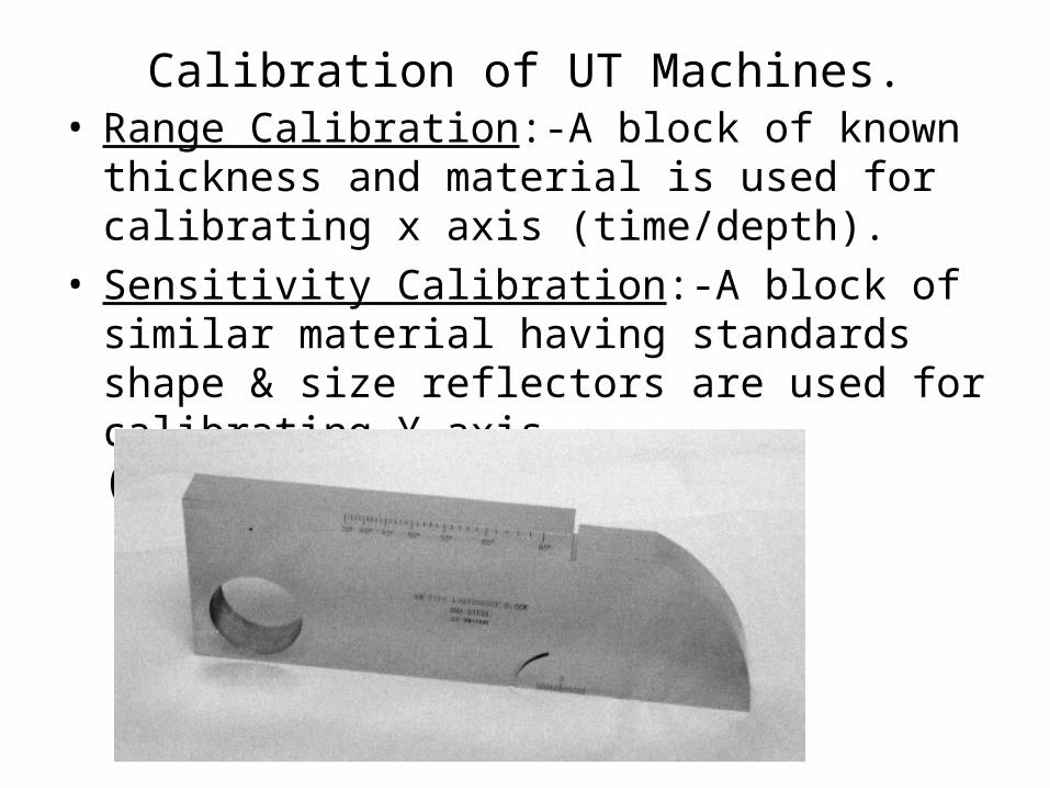
Calibration of UT Machines.• Range Calibration:-A block of known thickness
and material is used for calibrating x axis (time/depth).
• Sensitivity Calibration:-A block of similar material having standards shape & size reflectors are used for calibrating Y axis (amplitude/size).

IIW V1 Block

Test Techniques – Through-Transmission
0 2 4 6 8 10
2
11
• Two transducers located on opposing sides of the test specimen are used. One transducer acts as a transmitter, the other as a receiver.
• Discontinuities in the sound path will result in a partial or total loss of sound being transmitted and be indicated by a decrease in the received signal amplitude.
• Through transmission is useful in detecting discontinuities that are not good reflectors, and when signal strength is weak. It does not provide depth information.
T R
T R
11
2

Digital display showing received sound through material thickness.
Digital display showing loss of received signal due to presence of a discontinuity in the sound field.
Test Techniques – Through-Transmission

Test Techniques – Normal and Angle Beam
• In normal beam testing, the sound beam is introduced into the test article at 90 degree to the surface.
• In angle beam testing, the sound beam is introduced into the test article at some angle other than 90.
• The choice between normal and angle beam inspection usually depends on two considerations:
- The orientation of the feature of interest – the sound should be directed to produce the largest reflection from the feature.
- Obstructions on the surface of the part that must be worked around.


Angle beam probe calibration
IIW V2 Block
S1=25mmS2=50mm
Block Factor-25+50=75mm
1st echo-25mmIInd echo-25+BF(75)=100mm

Snell’s Law

Refraction : 1st critical angle

Calibration of angle probe
• Step1. Connect DAC Calibration Adapter to the UT instrument and manipulate its delay regulator to get the 7mm UT instrument digital distance indication. Adjust amplitude of the indicated pulse to the 100% of the screen height. Mark the top of the pulse as a point 1 of the DAC curve.
• Step2. Change the delay of DAC Calibration Adapter to get the 75mm UT instrument digital distance indication. Reduce the Gain of UT instrument in 11dB. Mark the top of the pulse as a point 2 of the DAC curve
• Step3. Change the delay of DAC Calibration Adapter to get the 38mm UT instrument digital distance indication. Increase the Gain of UT instrument in 5dB. Mark the top of the pulse as a point 3 and create DAC curve

Spectrum of soundFrequency range Hz Description Example
0 - 20 Infrasound Earth quake
20 – 20,000 Audible sound Speech, music
> 20,000 Ultrasound Bat, Quartz crystal

gas liquid solid
Atomic structures
• low density• weak bonding
forces
• medium density• medium bonding
forces
• high density • strong bonding
forces• crystallographic
structure

T
Distance travelled
From this we derive:
c=λ/T or c= λf Wave equation
During one oscillation T the wave front propagates by the distance :

Wave propagation
AirWaterSteel, longSteel, trans
330 m/s
1480 m/s
3250 m/s
5920 m/s
Longitudinal waves propagate in all kind of materials.Transverse waves only propagate in solid bodies. Due to the different type of oscillation, transverse wavestravel at lower speeds.Sound velocity mainly depends on the density and E-modulus of the material.

Behaviour at an interface
Medium 1 Medium 2
Interface
Incoming wave Transmitted wave
Reflected wave

0 2 4 6 8 10
s
s
Wall thickness measurement
Corrosion

Through transmission testing
0 2 4 6 8 10
Through transmission signal
1
2
1
2
T
T
R
R
Flaw

Ultrasonic Probes
socket
crystal
Damping
Delay / protecting faceElectrical matchingCable
Straight beam probe Angle beam probeTR-probe

Block diagram: Ultrasonic Instrument
amplifier
work piece
probe
horizontal
sweep
clock
pulser
IP
BE
screen

Weld inspection
0 20 40 60 80 100
s
aa'
d
x
a = s sinßa = s sinß
a' = a - xa' = a - x
d' = s cosßd' = s cosß
d = 2T - t'd = 2T - t'
s
Lack of fusion
Work piece with welding
Fß = probe angles = sound patha = surface distancea‘ = reduced surface distanced‘ = virtual depthd = actual depthT = material thickness
ß

Straight beam inspection techniques:Direct contact,
single element probe
Direct contact,
dual element probeFixed delay
Immersion testingThrough transmission

surface = sound entry
backwall flaw
1 2
water delay
0 2 4 6 8 10 0 2 4 6 8 10
IE IEIP IP
BE BEF
1 2
Immersion testing