Embed Size (px)
Citation preview

5.1.6 Student Book © 2005 Propane Education & Research Council Page 1
Selection of proper dispenser transfer hoses, end valves and adapters relies on a thorough understanding of the functional requirements for the propane dispenser; that is, an analysis of the types of containers serviced by its operation.
In this module you will learn to:
5.1.6Selecting Dispenser Transfer
Hose(s), Hose End Valves, Hose Safety Devices, and Adapters
1. Select filling adapters based on the dispenser application (types of containers serviced) and hose-end valves to meet NFPA 58 code requirements
2. Apply NFPA 58 code requirements for selecting dispenser transfer hose(s)

5.1.6 Student Book © 2005 Propane Education & Research Council Page 1
Selecting filling adapters based on the dispenser application (types of containers serviced) and hose-end valves to meet NFPA 58 code requirements
NFPA 582004
6.22.3.10 A listed quick-acting shutoff valve shall be installed at the discharge end of the transfer hose.
Courtesy Sherwood Products
Figure 1. Quick-Acting Hose-End Valve (Cylinder Filling)

5.1.6 Student Book © 2005 Propane Education & Research Council Page 2
Figure 2. POL Filling Adapter
Courtesy Engineered Controls International, Inc (REGO)
Figure 3. Motor Fuel CylinderDisconnect Coupling Filing Adapter
Figure 4. Type-1 and OPD Filling Adapter

5.1.6 Student Book © 2005 Propane Education & Research Council Page 2
Figure 5. Female POL toHansen Quick Disconnect Valve
Filling Adapter
Figure 6. Female POL toLiquid Withdrawal Valve
Filling Adapter

5.1.6 Student Book © 2005 Propane Education & Research Council Page 3
Courtesy Fisher Controls
Figure 7. 1¾-inch ACME Minimum Loss Hose-End Valve
Courtesy Engineered Controls International, Inc (REGO)
Figure 8. 1¾-inch ACME Minimum Loss Hose-End Valve

5.1.6 Student Book © 2005 Propane Education & Research Council Page 3
Applying NFPA 58 code requirements to selecting dispenser transfer hose(s) and hose protection devices
NFPA 582004
Vehicle fuel dispenser requirements
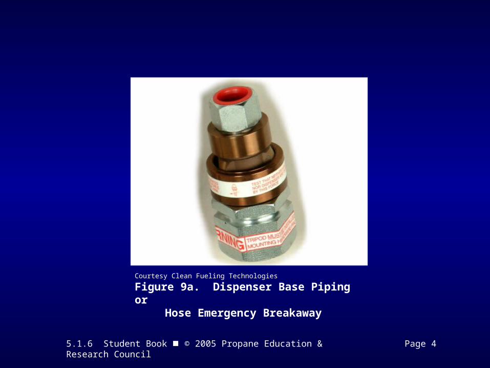
6.22.3.5 An excess-flow check valve or a differential back pressure valve shall be installed in or on the dispenser at the point at which the dispenser hose is connected to the liquid piping. 6.22.4.2 A listed emergency breakaway device complying with UL 567, Standard Pipe Connectors for Flammable and Combustible Liquids and LP-Gas, and designed to retain liquid on both sides of the breakaway point, or other devices affording equivalent protection approved by the authority having jurisdiction, shall be installed.
5.1.6 Student Book © 2005 Propane Education & Research Council Page 4
Courtesy Clean Fueling Technologies
Figure 9a. Dispenser Base Piping or Hose Emergency Breakaway

5.1.6 Student Book © 2005 Propane Education & Research Council Page 4
Courtesy Engineered Controls International, Inc (REGO)
Figure 9b. Dispenser Hose Emergency Breakaway

5.1.6 Student Book © 2005 Propane Education & Research Council Page 5
NFPA 582004
5.8.6.4 Hose, hose connections, and flexible connectors used for conveying LP-Gas liquid or vapor at pressures in excess of 5 psig, and as provided in Section 6.17 regardless of the pressure, shall comply with 5.8.6.4(A) through 5.8.6.4(D).
(A) Hose shall be designed for a working pressure of 350 psig with a safety factor of 5 to 1 and shall be continuously marked with LP-GAS, PROPANE, 350 PSI WORKING PRESSURE, and with the manufacturer’s name or trademark.
(B) Hose assemblies, after the application of couplings, shall have a design capability of not less than 700 psig.
(C) If a pressure test is performed, such assemblies shall be pressure tested at 120 percent of the maximum working pressure (350 psig minimum) of the hose.
(D) Hose assemblies shall be leak tested at time of installation at not less than the operating pressure of the system in which they are installed.

5.1.6 Student Book © 2005 Propane Education & Research Council Pages 5 & 6
NFPA 582004
6.22.4.1 Hoses shall comply with the following:
(1) Hose length shall not exceed 18 feet unless approved by the authority having jurisdiction.
(2) All hoses shall be listed. (3) When not in use, hoses shall be secured to protect them
from damage.
6.8.7.2 Flexible connectors and hose used as flexible connectors shall not exceed 36 inches in length where used with liquid or vapor piping on portable or stationary tanks.
6.11 Hydrostatic Relief Valve Installation. A hydrostatic relief valve or a device providing pressure-relieving protection shall be installed in each section of piping and hose in which liquid LP-Gas can be isolated between shutoff valves so as to relieve the pressure that could develop from the trapped liquid to a safe atmosphere or product-retaining section..

5.1.6 Student Book © 2005 Propane Education & Research Council Page 6
Figure 10. Hydrostatic Relief Valve with Weather CapProtecting Pipe and Connected Hose

5.1.6 Student Book © 2005 Propane Education & Research Council Pages 7 - 9
Time to See If You Got the Key Points of This Module…
• Complete the Review on pages 7 & 8.
• See if you are ready for the Certification Exam by checking off the performance criteria on page 9.