Embed Size (px)
Citation preview
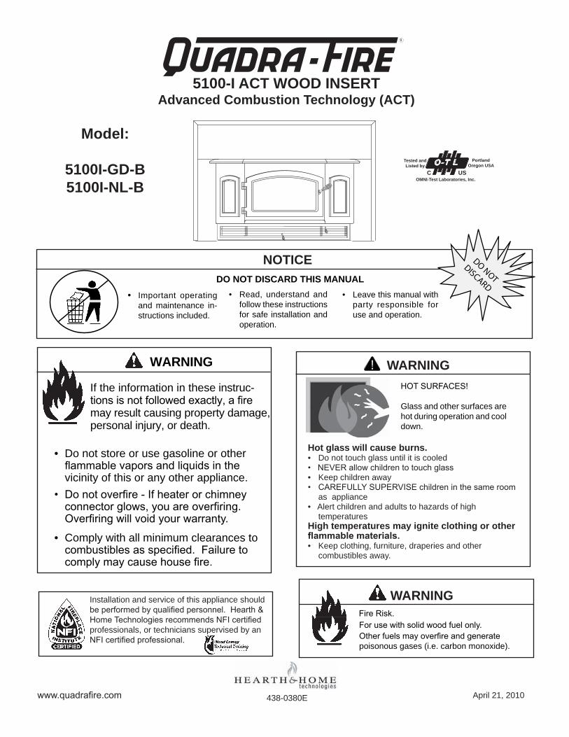
DO NOT DISCARD THIS MANUAL
NOTICE
• Important operatingand maintenance in-structionsincluded.
• Leavethismanualwithparty responsible foruseandoperation.
• Read, understand andfollowtheseinstructionsforsafeinstallationandoperation.
DO NOTDISCARD
WARNING
Iftheinformationintheseinstruc-tions is not followed exactly, a fire mayresultcausingpropertydamage,personalinjury,ordeath.
• Donotstoreorusegasolineorotherflammable vapors and liquids in the vicinityofthisoranyotherappliance.
• Do not overfire - If heater or chimney connector glows, you are overfiring. Overfiring will void your warranty.
• Complywithallminimumclearancestocombustibles as specified. Failure to comply may cause house fire.
www.quadrafire.com
5100-I ACT WOOD INSERTAdvanced Combustion Technology (ACT)
438-0380E
R
Installationandserviceofthisapplianceshouldbe performed by qualified personnel. Hearth & Home Technologies recommends NFI certified professionals,ortechnicianssupervisedbyanNFI certified professional.
Fire Risk.
WARNING
For use with solid wood fuel only.Other fuels may overfire and generate poisonousgases(i.e.carbonmonoxide).
April21,2010
HOT SURFACES!
Glassandothersurfacesarehotduringoperationandcooldown.
WARNING
Hot glass will cause burns.• Donottouchglassuntilitiscooled• NEVER allow children to touch glass• Keepchildrenaway• CAREFULLY SUPERVISE children in the same room
asappliance•Alertchildrenandadultstohazardsofhigh
temperaturesHigh temperatures may ignite clothing or other flammable materials.• Keepclothing,furniture,draperiesandother
combustiblesaway.
Model:
5100I-GD-B5100I-NL-B
O-T LTested and Listed by
PortlandOregon USA
OMNI-Test Laboratories, Inc.C US
5100-I ACT WOOD INSERT
Page � April21,2010
R
438-0380E
and Welcome to the Quadra-Fire Family!
Hearth & Home Technologies welcomes you to our tradition of excellence! In choosing a Quadra-Fire appliance, you have our assurance of commitment to quality, durability, and perfor-mance.
This commitment begins with our research of the market, includ-ing ‘Voice of the Customer’ contacts, ensuring we make prod-uctsthatwillsatisfyyourneeds.OurResearchandDevelopmentfacility then employs the world’s most advanced technology to
achieve the optimum operation of our stoves, inserts and fire-places.Andyetweareold-fashionedwhenitcomestocrafts-manship.Eachunitismeticulouslyfabricatedandsurfacesarehand-finished for lasting beauty and enjoyment. Our pledge to quality is completed as each model undergoes a quality control inspection.
Wewishyouandyour familymanyyearsofenjoyment in thewarmth and comfort of your hearth appliance. Thank you for choosing Quadra-Fire.
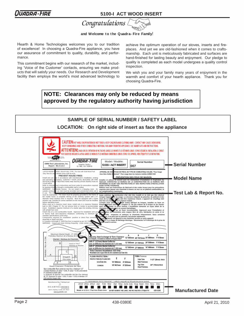
SAMPLE OF SERIAL NUMBER / SAFETY LABELLOCATION: On right side of insert as face the appliance
U.S. ENVIRONMENTAL PROTECTION AGENCY - Certified to comply with July 1990 particulate emission standards.
2010 2011 2012 Jan Feb Mar Apr May June July Aug Sept Oct. Nov. Dec.
438-0390 1445 N. Highway, Colville, WA 99114 Made in U.S.A. / Fait Aux États-Unis DO NOT REMOVE THIS LABEL / NE PAS ENLEVER L'ÉTIQUETTE
Manufactured by / Fabriqué par:
Non-combustible floor protector must be a minimum 1/2” (13mm) thickness (k value = 0.84, R value = 0.59) and extend 8" (203mm) to both sides. La protection de plancher non-combustible doit être d’un minimum de 1/2” d’paisseur (k value = 0.84, R value = 0.59) et étendue à 8" (203 mm) de chaque côtés.
Mantel / Manteau de Cheminée
Hearth Extension / Extension de l'âtre
A
B
C
D
F E
Insert Pièce Insérée
Sid
eWal
l / M
ur d
e C
ôté
Maximum Mantel Depth - 8" (203mm) Profondeur Maximum de la Manteau de Cheminée -
Fascia or Trim / Panneau ou Moulure
www.quadrafire.com
with 5" (127mm) Mantel Deflector avec un déflecteur de cheminée de 5" (127 mm) with 8" (203mm) Mantel Deflector avec un déflecteur de cheminée de 8" (203 mm)
35"/889mm 20"/508mm 16"/406mm
C 7"/178mm 7"/178mm 7"/178mm
D
CANADA
40"/1015mm 31"/787mm 27"/686mm
12"/305mm 12"/305mm 12"/305mm
USA/États-Unis 8"/203mm 8"/203mm
F 16"/406mm 18"/457mm
E FLOOR PROTECTION / PROTECTION DU PLANCHER
*Zero Clearance Installations USA Only *Installation avec espace libre de zéro seulement aux États-Unis
Masonry, Heat Exchanger & *Zero Clearance En briques, Circulant la chaleur & d'espace libre*
B A
Side Trim Muir Panneau Top Trim Haut Panneau
1-1/2” (38mm) thick 3/4” (19mm) thick
TRIM / Panneau
Serial Number OMNI-Test Laboratories, Inc.
Report: 061-S-12-2
LISTED ROOM HEATER, SOLID FUEL TYPE. "For Use with Solid Wood Fuel Only."Also for use in Mobile Home (UM) 84 HUD.
R
Install and use only in accordance with manufacturer's installation, venting and operating instructions. CONTACT YOUR LOCAL BUILDING OR FIRE OFFICIALS ABOUT RESTRICTIONS AND INSTALLATION INSPECTION IN YOUR AREA Refer to manufacturer's instructions and local codes for precautions required for passing chimney through a combustible wall or ceiling. WARNING - For Mobile Homes: Do not install in a sleeping room. An outside combustion air inlet must be provided and unrestricted while unit is in use. The structural integrity of the mobile home floor, ceiling and walls must be maintained. The insert must be properly grounded to the frame of the mobile home. A complete relining of the chimney system with a 6" diameter listed stainless liner is required. Must be equipped with a spark arrestor cap. Outside Air comes standard on the insert and must be installed before operating insert. When used as a masonry insert stove, install only in a masonry fireplace built to UBC Chapter 37. Do not remove brick or mortar to accommodate insert. Installation requires minimum of a starter pipe into existing chimney with airtight face seal. Install only on a non-combustible hearth. Approved for installation and use in factory built zero-clearance fireplaces conforming to minimum fire chamber specifications (USA only). Components required for installation: positive or direct flue connection assembly or listed vent liner. In Canada a full length 6" S635 flue liner is required as per ULC S628. WARNING - Inspect and clean chimney frequently. Under certain conditions of
PREVENT HOUSE FIRES
CAUTION:HOT WHILE IN OPERATION DO NOT TOUCH, KEEP CHILDREN AND CLOTHING AWAY. CONTACT MAY CAUSE SKIN BURNS.
Model / Modèle: 5100-I ACT INSERT
Tested to / Testé a: UL 1482, ULC S628-93
PRÉVENTION DES FEUX DE MAISON Installez et utilisez en accord avec les instructions d'installation et d'opération du fabricant. CONTACTEZ LE BUREAU DE LA CONSTRUCTION OU LE BUREAU DES INCENDIES AU SUJET DES RESTRICTIONS ET DES INSPECTIONS D'INSTALLATION DANS VOTRE VOISINAGE. Référez vous aux instructions du fabricant et des codes locaux pour les précautions requises pour passer une cheminée à travers un mur ou un plafond combustibles, et les compensations maximums. AVIS - Pour Les Maisons Mobiles: Ne pas installer dans une chambre à coucher. Un tuyau extérieur de combustion d'air doit être installé et ne doit pas être obstrué lorsque l'appareil est en usage. La structure intégrale du plancher, du plafond et des murs de la maison mobile doit être maintenue intacte. L'appareil de chauffage doit être fixé à la charpente de la maison mobile. . Lorsque vous utilisez un poêle inséré fabriqué en briques, installez un foyer en briques fabriqué selon UBC Chapitre 37. Ne pas enlever de la brique ou du mortier pour accommoder la pièce insérée. L'installation demande un tuyau allant de la cheminée existante avec un couvert hermétique. Installez seulement sur un foyer incombustible. Approuvé pour l'installation et l'usage dans les cheminées avec espace libre de zéro, fabriquées en usine et se
ATTENTION:CHAUD LORS DE L'OPÉRATION. NE PAS TOUCHER. GARDEZ LES ENFANTS ET LES VÊTEMENTS LOIN DE L'ESPACE DÉSIGNÉ DE L'INSTALLATION. LE CONTACT PEUT CAUSER DES BRÛLURES À LA PEAU. GARDEZ LES MEUBLES ET LES MATÉRIAUX COMBUSTIBLES LOIN DE L'ESPACE DE L'APPAREIL. VOIR L'ÉTIQUETTE ET LES INSTRUCTIONS.
APPAREIL DE CHAUFFAGE DE PIÈCE, DE TYPE DE COMBUSTIBLE SOLIDE, "Pour Usage Avec Bois Solide Seulement" Pour usage dans les maisons mobiles (UM)84 HUD
ATTENTION! Inspectez et nettoyez la cheminée fréquemment. Sous certaines conditions, il se peut que la créosote s'accumule rapidement. Ne pas connecter cet appareil à une cheminée servant un autre appareil. DANGER: Il y a risque de décharge électrique. Déconnectez le fil électrique de la prise de contact avant le service.
KEEP FURNISHINGS AND OTHER COMBUSTIBLE MATERIAL FAR AWAY FROM THE APPLIANCE. SEE NAMEPLATE AND INSTRUCTIONS.
SAMPLE
007
O-T LTested and Listed by
PortlandOregon USA
OMNI-Test Laboratories, Inc.C US
Model Name
Serial Number
Manufactured Date
Test Lab & Report No.
NOTE: Clearances may only be reduced by means approved by the regulatory authority having jurisdiction
Page �
5100-I ACT WOOD INSERTR
438-0380EApril21,2010
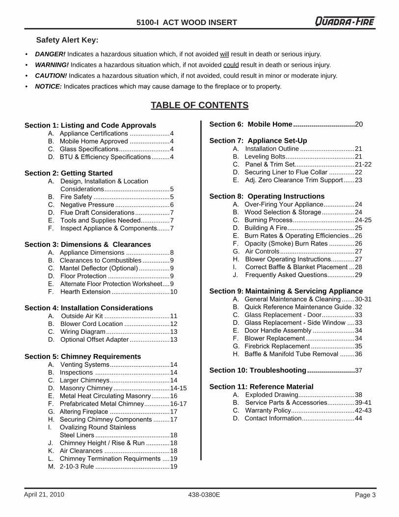
Section 1: Listing and Code Approvals A. Appliance Certifications......................4 B. Mobile Home Approved......................4 C. Glass Specifications............................4 D. BTU & Efficiency Specifications..........4
Section 2: Getting Started A. Design, Installation & Location Considerations....................................5 B. Fire Safety..........................................5 C. Negative Pressure..............................6
D. Flue Draft Considerations...................7 E. Tools and Supplies Needed................7 F. Inspect Appliance & Components.......7Section 3: Dimensions & Clearances A. ApplianceDimensions........................8 B. ClearancestoCombustibles...............9 C. Mantel Deflector (Optional).................9 D. Floor Protection..................................9 E. Alternate Floor Protection Worksheet....9 F. Hearth Extension................................10
Section 4: Installation Considerations A. OutsideAirKit....................................11 B. BlowerCordLocation.........................12 C. WiringDiagram...................................13 D. OptionalOffsetAdapter......................13
Section 5: Chimney Requirements A. Venting Systems.................................14 B. Inspections.........................................14 C. LargerChimneys.................................14 D. MasonryChimney...............................14-15 E. Metal Heat Circulating Masonry..........16 F. Prefabricated Metal Chimney..............16-17 G. Altering Fireplace.................................17 H. Securing Chimney Components.........17 I. Ovalizing Round Stainless Steel Liners.........................................18 J. Chimney Height / Rise & Run.............18 K. AirClearances....................................18 L. Chimney Termination Requirments....19 M. 2-10-3Rule.........................................19
Section 6: Mobile Home ...............................20
Section 7: Appliance Set-Up A. InstallationOutline..............................21 B. LevelingBolts......................................21 C. Panel & Trim Set.................................21-22 D. Securing Liner to Flue Collar..............22 E. Adj. Zero Clearance Trim Support......23
Section 8: Operating Instructions A. Over-Firing Your Appliance.................24 B. Wood Selection & Storage..................24
C. Burning Process..................................24-25 D. Building A Fire.....................................25 E. Burn Rates & Operating Efficiencies...26
F. Opacity (Smoke) Burn Rates..............26 G. AirControls.........................................27 H. Blower Operating Instructions.............27
I. Correct Baffle & Blanket Placement...28 J. Frequently Asked Questions...............29
Section 9: Maintaining & Servicing Appliance A. General Maintenance & Cleaning.......30-31 B. Quick Reference Maintenance Guide.32 C. GlassReplacement-Door..................33 D. Glass Replacement - Side Window....33 E. Door Handle Assembly.......................34 F. Blower Replacement...........................34 G. Firebrick Replacement........................35 H. Baffle & Manifold Tube Removal........36
Section 10: Troubleshooting ........................37
Section 11: Reference Material A. ExplodedDrawing...............................38 B. Service Parts & Accessories...............39-41 C. Warranty Policy...................................42-43 D. ContactInformation.............................44
TABLE OF CONTENTS
Safety Alert Key:
• DANGER! Indicatesahazardoussituationwhich,ifnotavoidedwillresultindeathorseriousinjury.• WARNING!Indicatesahazardoussituationwhich,ifnotavoidedcouldresultindeathorseriousinjury.• CAUTION! Indicatesahazardoussituationwhich,ifnotavoided,couldresultinminorormoderateinjury.• NOTICE: Indicates practices which may cause damage to the fireplace or to property.

5100-I ACT WOOD INSERT
Page � April21,2010
R
438-0380E
1 Listing and Code Approvals
The Quadra-Fire 5100-I ACT Wood Inserts meets the U.S. Environmental Protection Agency’s 1990 particulate emis-sionstandards.
MODEL: 5100-I ACT Wood Insert
LABORATORY: OMNI Test Laboratories, Inc.
REPORT NO. 061-S-59-�
TYPE: Solid Fuel Type, Wood Stove Insert
STANDARD: UL1�8� and ULC S6�8 and (UM) 8�-HUD, Mobile Home Approved.
A. Appliance Certification
C. Glass Specifications
D. BTU & Efficiency Specifications
This appliance is equipped with 5mm ceramic glass. Replace glass only with 5mm ceramic glass. Please contactyourdealerforreplacementglass.
This appliance is approved for mobile home installations whennotinstalledinasleepingroomandwhenanoutsidecombustion air inlet is provided. The structural integrity of the mobile home floor, ceiling, and walls must be maintained. The appliance must be properly grounded to the frame of themobilehomeanduseonlylisteddouble-wallconnectorpipe.AnOutsideAirKitcomesstandardontheapplianceandmustbeinstalledinamobilehomeinstallation.
B. Mobile Home Approved
NOTE: Hearth & Home Technologies grants no war-ranty,impliedorstated,fortheinstallationormainte-nanceofthisunitandassumesnoresponsibilityforany consequential damage(s).
NOTE: This installation must conform with local codes. IntheabsenceoflocalcodesyoumustcomplywiththeUL1482, (UM) 84-HUD and NFPA211 in the U.S.A. and theULC S628-93 and CAN/CSA-B365 Installation Codes inCanada.
• Installationanduseofanydamagedappliance.• Modification of the appliance.• Installation other than as instructed by Hearth & Home
Technologies.• Installation and/or use of any component part not approved
by Hearth & Home Technologies.• Operating appliance without fully assembling all
components.• Operatingappliancewithoutlegsattached(ifsuppliedwith
unit).• Do NOT Overfire - If appliance or chimney connector glows,
you are overfiring.Any such action that may cause a fire hazard.
WARNINGFire Risk.Hearth & Home Technologies disclaims any responsibilityfor,andthewarrantywillbevoided by, the following actions:
EPA Certified: 1.9 grams/hourEfficiency: upto84.4%BTU Output: 11,600to48,200Heating Capacity: �,�50 to �,175 sq ft depending on
climatezoneMaximum Log Length: 12inchesFirebox Capacity: 3.0cubicfeetWeight: 520lbs
Quadra-Fire is a registered trademark of Hearth & Home Technologies. NOTE: Hearth & Home Technologies, manufacturer of
thisappliance,reservestherighttoalteritsproducts,their specifications and/or price without notice.
Page 5
5100-I ACT WOOD INSERTR
438-0380EApril21,2010
Improperinstallation,adjustment,alteration,serviceormaintenancecancauseinjuryorpropertydamage.Referto the owner’s information manual provided with this appli-ance. For assistance or additional information consult a qualified installer, service agency or your dealer.
WARNING
2 Getting Started
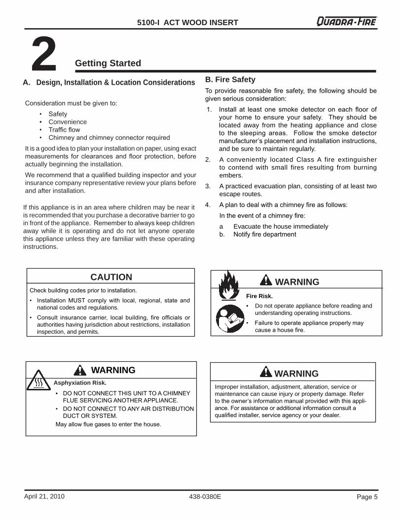
A. Design, Installation & Location Considerations
Consideration must be given to: • Safety • Convenience • Traffic flow • Chimney and chimney connector requiredItisagoodideatoplanyourinstallationonpaper,usingexactmeasurements for clearances and floor protection, before actuallybeginningtheinstallation.We recommend that a qualified building inspector and your insurancecompanyrepresentativereviewyourplansbeforeandafterinstallation.
Ifthisapplianceisinanareawherechildrenmaybenearitisrecommendedthatyoupurchaseadecorativebarriertogoinfrontoftheappliance.Remember to always keep children away while it is operating and do not let anyone operatethisapplianceunlesstheyarefamiliarwiththeseoperatinginstructions.
B. Fire SafetyTo provide reasonable fire safety, the following should be given serious consideration:1. Install at least one smoke detector on each floor of
your home to ensure your safety. They should be located away from the heating appliance and closeto the sleeping areas. Follow the smoke detector manufacturer’s placement and installation instructions, andbesuretomaintainregularly.
2. A conveniently located ClassA fire extinguisherto contend with small fires resulting from burningembers.
3. Apracticedevacuationplan,consistingofatleasttwoescaperoutes.
�. A plan to deal with a chimney fire as follows: In the event of a chimney fire:
a Evacuatethehouseimmediatelyb. Notify fire department
WARNING
• DO NOT CONNECT THIS UNIT TO A CHIMNEY FLUE SERVICING ANOTHER APPLIANCE.
• DO NOT CONNECT TO ANY AIR DISTRIBUTION DUCT OR SYSTEM.
May allow flue gases to enter the house.
Asphyxiation Risk.
Fire Risk.
WARNING
• Donotoperateappliancebeforereadingandunderstandingoperatinginstructions.
• Failure to operate appliance properly may cause a house fire.
Check building codes prior to installation.
• Installation MUST comply with local, regional, state and nationalcodesandregulations.
• Consult insurance carrier, local building, fire officials or authoritieshavingjurisdictionaboutrestrictions,installationinspection,andpermits.
CAUTION
5100-I ACT WOOD INSERT
Page 6 April21,2010
R
438-0380E
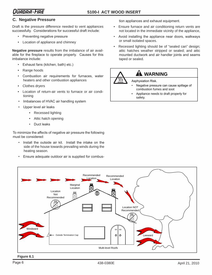
C. Negative PressureDraft isthepressuredifferenceneededtoventappliancessuccessfully. Considerations for successful draft include: • Preventing negative pressure • Locationofapplianceandchimney
Negative pressure resultsfromtheimbalanceofairavail-able for the fireplace to operate properly. Causes for this imbalance include: • Exhaust fans (kitchen, bath) etc.) • Rangehoods • Combustion air requirements for furnaces, water
heatersandothercombustionappliances • Clothesdryers • Location of return-air vents to furnace or air condi-
tioning
Recommended Location
MarginalLocation
LocationNot
Recommended
Recommended
Location
Location NOT
Recommended
Multi-level Roofs
Windward
LeewardOutside Termination Cap
Figure 6.1
• Imbalances of HVAC air handling system • Upper level air leaks • Recessedlighting • Attichatchopening • Duct leaks
To minimize the affects of negative air pressure the following must be considered: • Install the outside air kit. Install the intake on the
sideofthehousetowardsprevailingwindsduringtheheatingseason.
• Ensure adequate outdoor air is supplied for combus-
Asphyxiation Risk.• Negative pressure can cause spillage of
combustionfumesandsoot• Applianceneedstodraftproperlyfor
safety.
WARNING
tion appliances and exhaust equipment. • Ensurefurnaceandairconditioningreturnventsare
notlocatedintheimmediatevicinityoftheappliance, • Avoid installing the appliance near doors, walkways
orsmallisolatedspaces. • Recessedlightingshouldbeof“sealedcan”design;
attic hatches weather stripped or sealed; and atticmounted ductwork and air handler joints and seams tapedorsealed.

Page 7
5100-I ACT WOOD INSERTR
438-0380EApril21,2010
D. Flue Draft Considerations
Location of the appliance and chimney will affect perfor-mance. As shown in Figure 6.1 on page 6 the chimneyshould: • Beinstalledthroughthewarmspaceenclosedbythe
building envelope. This helps to produce more draft, especially during lighting and die down of the fire.
• Penetrate the highest part of the roof. This minimizes theaffectsofwindturbulence.
• Consider the appliance location to the floor and ceil-ingatticjoists.
Exterior conditions such as roof line, surrounding trees,prevailing winds and nearby hills can influence appliance performance. Your local dealer is the expert in your geographic area and can usually make suggestions or discover solutions that will easily correct your flue problem.
Tobesurethatyourapplianceburnsproperly, thechimneydraft(staticpressure)shouldbeapproximately-.10inchwatercolumn(W.C.)duringahighburnand-.04inchW.C.duringalowburn,measured6inches(152mm)abovethetopoftheapplianceafteronehourofoperationateachburnsetting.
NOTE: These are guidelines only, and may vary somewhat
F. Inspect Appliance and Components
E. Tools And Supplies NeededBeforebeginningtheinstallationbesurethatthefollowingtoolsandbuildingsuppliesareavailable.
• Open the appliance and remove all the parts andarticles packed inside.
• Inspectallthepartsandglassforshippingdamage.
• Contactyourdealerifanyirregularitiesarenoticed.
• Removedalllabelsfromtheglassdoors.
• Wipe clean all plated surfaces before first fire.
ReciprocatingsawPliersHammerPhillips ScrewdriverFlat Blade ScrewdriverPlumb LineLevelTape Measure
Framing MaterialHi-Temp Caulking MaterialGlovesFraming SquareElectric Drill & Bits (1/�”)Safety Glasses1/�” - �/�” length, #6 or #8 selfdrillingscrews(youwillneed3perpipesectionconnection+10)
Inspectapplianceandcomponentsfordamage.Damagedpartsmayimpairsafeoperation.
WARNING
• Do NOT install damaged components.• Do NOT install incomplete components.• Do NOT install substitute components.
Reportdamagedpartstodealer.
5100-I ACT WOOD INSERT
Page 8 April21,2010
R
438-0380E
3Dimensions and Clearances
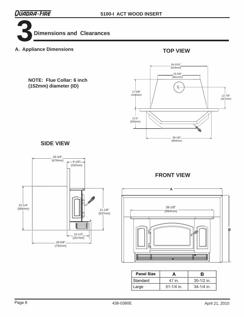
A. Appliance Dimensions TOP VIEW
SIDE VIEW
FRONT VIEW
A
B
39-1/8" (994mm)
26-3/4" (679mm) 9-1/8"
(232mm)
22-1/4" (565mm) 21-1/8"
(537mm)
29-5/8" (752mm)
10-1/2" (267mm)
34-3/16" (919mm)
CL
25-5/8" (651mm)
12-7/8" (327mm)
17-5/8" (448mm)
39-1/8" (994mm)
12.0" (305mm)
NOTE: Flue Collar: 6 inch (152mm) diameter (ID)
Panel Size A BStandard 47in. �0-1/� in.Large 51-1/� in. ��-1/� in.
Page 9
5100-I ACT WOOD INSERTR
438-0380EApril21,2010
Hearth Extension
A
B
C
F E
Insert
Side
Wal
l Fascia or Trim
Mantel
D
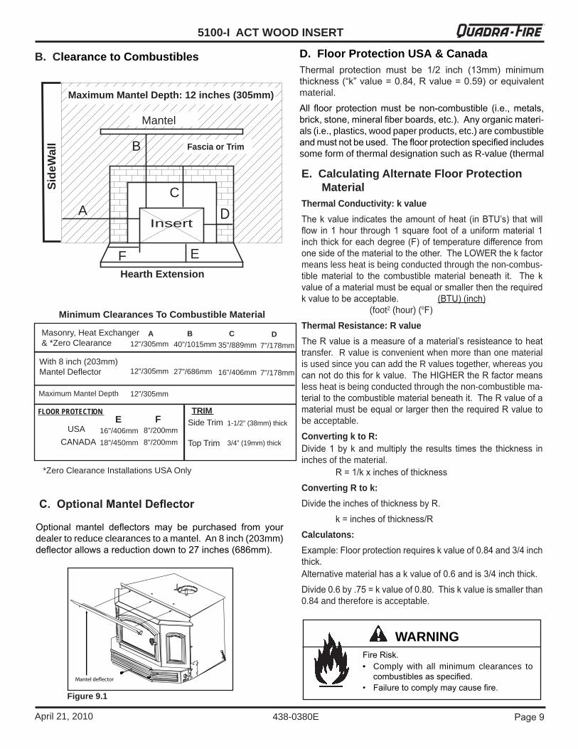
Maximum Mantel Depth: 12 inches (305mm)
B. Clearance to Combustibles
C. Optional Mantel Deflector
Optional mantel deflectors may be purchased from your dealertoreduceclearancestoamantel.An8inch(203mm)deflector allows a reduction down to �7 inches (686mm).
Figure 9.1
• Comply with all minimum clearances tocombustibles as specified.
• Failure to comply may cause fire.
WARNINGFire Risk.
Minimum Clearances To Combustible Material
With 8 inch (203mm) Mantel Deflector
35"/889mm
16"/406mm
C7"/178mm
7"/178mm
D
CANADA
40"/1015mm
27"/686mm
12"/305mm
12"/305mm
USA 8"/200mm8"/200mm
F16"/406mm18"/450mm
EFLOOR PROTECTION
*Zero Clearance Installations USA Only
Masonry, Heat Exchanger & *Zero Clearance
BA
Side Trim
Top Trim
1-1/2” (38mm) thick
3/4” (19mm) thick
TRIM
Maximum Mantel Depth 12”/305mm
Thermal protection must be 1/� inch (1�mm) minimum thickness (“k” value = 0.8�, R value = 0.59) or equivalent material.All floor protection must be non-combustible (i.e., metals, brick, stone, mineral fiber boards, etc.). Any organic materi-als(i.e.,plastics,woodpaperproducts,etc.)arecombustibleand must not be used. The floor protection specified includes someformofthermaldesignationsuchasR-value(thermal
D. Floor Protection USA & Canada
E. Calculating Alternate Floor Protection Material
Thermal Conductivity: k valueThe k value indicates the amount of heat (in BTU’s) that will flow in 1 hour through 1 square foot of a uniform material 1 inch thick for each degree (F) of temperature difference from one side of the material to the other. The LOWER the k factor meanslessheatisbeingconductedthroughthenon-combus-tible material to the combustible material beneath it. The k value of a material must be equal or smaller then the required k value to be acceptable. (BTU) (inch) (foot2(hour)(oF)Thermal Resistance: R valueThe R value is a measure of a material’s resisteance to heat transfer.RvalueisconvenientwhenmorethanonematerialisusedsinceyoucanaddtheRvaluestogether,whereasyoucan not do this for k value. The HIGHER the R factor means lessheatisbeingconductedthroughthenon-combustiblema-terial to the combustible material beneath it. The R value of a material must be equal or larger then the required R value to beacceptable.Converting k to R:Divide 1 by k and multiply the results times the thickness in inchesofthematerial. R = 1/k x inches of thicknessConverting R to k:Divide the inches of thickness by R. k = inches of thickness/RCalculatons:Example: Floor protection requires k value of 0.8� and �/� inch thick.Alternative material has a k value of 0.6 and is �/� inch thick.Divide 0.6 by .75 = k value of 0.80. This k value is smaller than 0.84andthereforeisacceptable.
5100-I ACT WOOD INSERT
Page 10 April21,2010
R
438-0380E
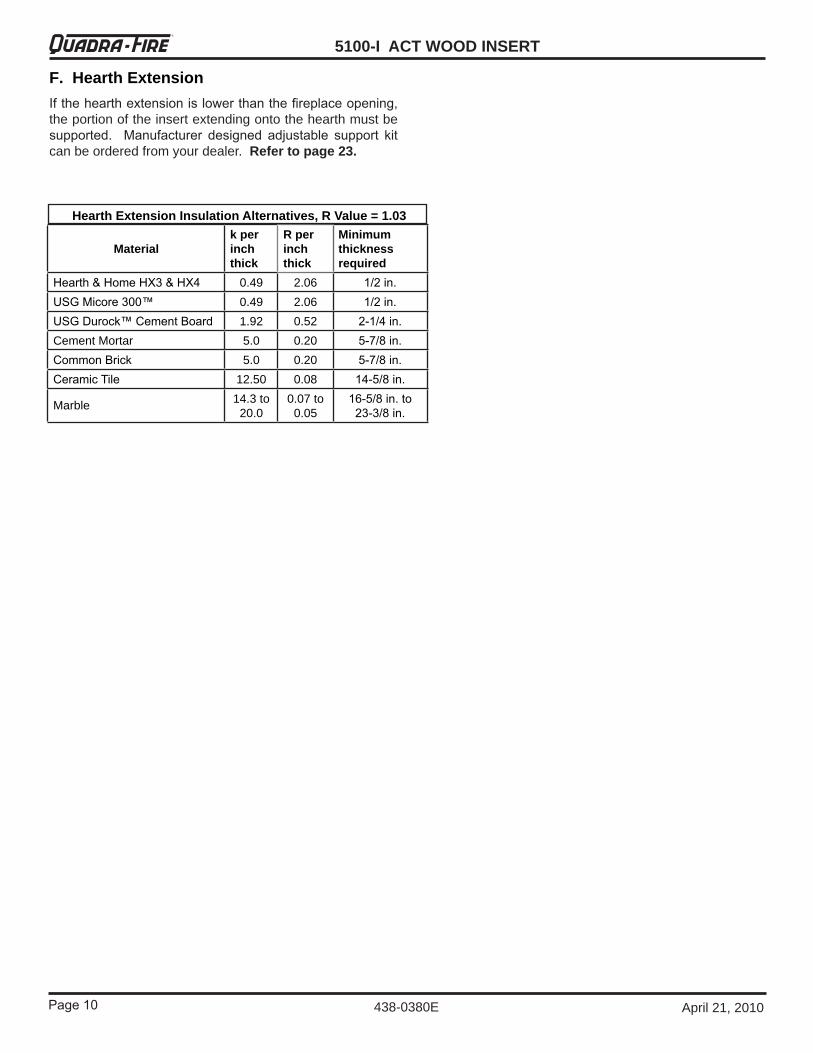
F. Hearth ExtensionIf the hearth extension is lower than the fireplace opening, theportionoftheinsertextendingontothehearthmustbesupported. Manufacturer designed adjustable support kit canbeorderedfromyourdealer.Refer to page 23.
Materialk per inch thick
R per inch thick
Minimum thickness required
Hearth & Home HX� & HX� 0.49 2.06 1/� in.USG Micore �00™ 0.49 2.06 1/� in.USG Durock™ Cement Board 1.92 0.52 �-1/� in.CementMortar 5.0 0.20 5-7/8 in.Common Brick 5.0 0.20 5-7/8 in.Ceramic Tile 12.50 0.08 1�-5/8 in.
Marble 14.3to20.0
0.07to0.05
16-5/8 in. to ��-�/8 in.
Hearth Extension Insulation Alternatives, R Value = 1.03
Page 11
5100-I ACT WOOD INSERTR
438-0380EApril21,2010
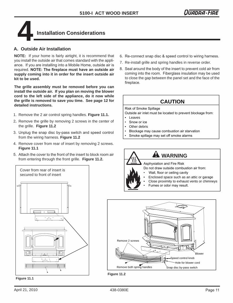
NOTE: Ifyourhomeisfairlyairtight,itisrecommendthatyouinstalltheoutsideairthatcomesstandardwiththeappli-ance. If you are installing into a Mobile Home, outside air is required. NOTE: The fireplace must have an outside air supply coming into it in order for the insert outside air kit to be used.
The grille assembly must be removed before you can install the outside air. If you plan on moving the blower cord to the left side of the appliance, do it now while the grille is removed to save you time. See page 12 for detailed instructions.
1. Removethe2aircontrolspringhandles.Figure 11.1. 2. Removethegrillebyremoving2screwsinthecenterof
thegrille.Figure 11.2�. Unplug the snap disc by-pass switch and speed control
fromthewiringharness.Figure 11.2 4. Removecoverfromrearofinsertbyremoving2screws.
Figure 11.15. Attach the cover to the front of the insert to block room air
fromenteringthroughthefrontgrille.Figure 11.2.
A. Outside Air Installation
Remove 2 screws
Remove both spring handles Snap disc by-pass switch
Speed control knob
Hole for blower cord
Blower
Figure 11.1Figure 11.2
CAUTIONRisk of Smoke SpillageOutside air inlet must be located to prevent blockage from:• Leaves• Snow or ice• Otherdebris• Blockage may cause combustion air starvation• Smoke spillage may set off smoke alarms
WARNINGAsphyxiation and Fire RiskDo not draw outside combustion air from:• Wall, floor or ceiling cavity• Enclosedspacesuchasanatticorgarage• Closeproximitytoexhaustventsorchimneys• Fumes or odor may result.
4 Installation Considerations
6. Re-connect snap disc & speed control to wiring harness. 7. Re-installgrilleandspringhandlesinreverseorder.8. Seal around the body of the insert to prevent cold air from
coming into the room. Fiberglass insulation may be used toclosethegapbetweenthepanelsetandthefaceofthefireplace.
Coverfromrearofinsertissecuredtofrontofinsert
5100-I ACT WOOD INSERT
Page 1� April21,2010
R
438-0380E
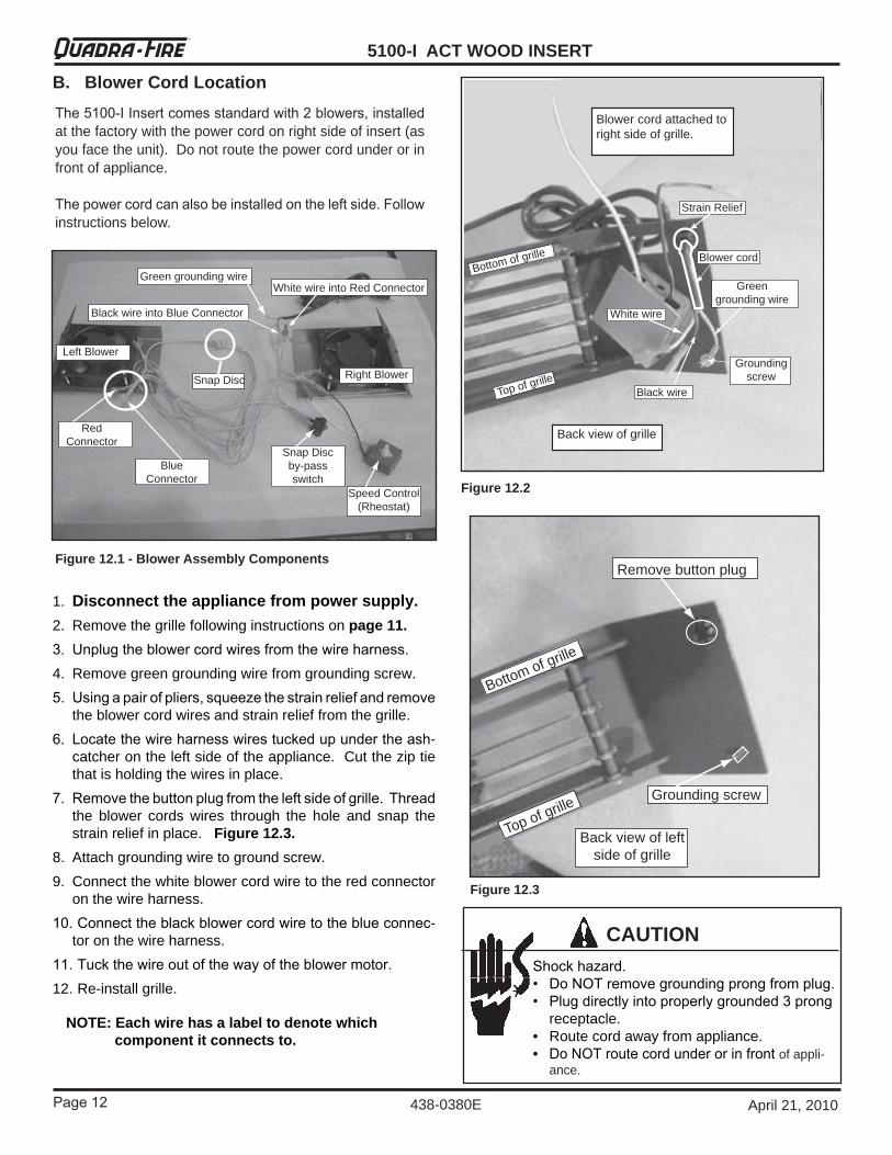
The 5100-I Insert comes standard with � blowers, installed atthefactorywiththepowercordonrightsideofinsert(asyoufacetheunit).Donotroutethepowercordunderorinfrontofappliance.
The power cord can also be installed on the left side. Follow instructionsbelow.
B. Blower Cord Location
Shock hazard.• Do NOT remove grounding prong from plug.• Plug directly into properly grounded � prong
receptacle.• Routecordawayfromappliance.• Do NOT route cord under or in front ofappli-
ance.
CAUTION
Figure 12.1 - Blower Assembly Components
Snap Disc
Snap Disc by-pass switch
Speed Control (Rheostat)
Right Blower
Left Blower
Red Connector
Blue Connector
White wire into Red Connector
Black wire into Blue Connector
Green grounding wire
Grounding screw
Green grounding wire
Blower cord
Black wire
White wire
Strain Relief
Bottom of grille
Top of grille
Back view of grille
Blower cord attached to right side of grille.
Remove button plug
Grounding screw
Back view of left side of grille
Bottom of grille
Top of grille
1. Disconnect the appliance from power supply.2. Removethegrillefollowinginstructionsonpage 11.�. Unplug the blower cord wires from the wire harness.4. Removegreengroundingwirefromgroundingscrew.5. Using a pair of pliers, squeeze the strain relief and remove
theblowercordwiresandstrainrelieffromthegrille.6. Locate the wire harness wires tucked up under the ash-
catcherontheleftsideoftheappliance.Cuttheziptiethatisholdingthewiresinplace.
7. Remove the button plug from the left side of grille. Thread the blower cords wires through the hole and snap thestrainreliefinplace.Figure 12.3.
8. Attachgroundingwiretogroundscrew.9. Connectthewhiteblowercordwiretotheredconnector
onthewireharness.10. Connect the black blower cord wire to the blue connec-
toronthewireharness.11. Tuck the wire out of the way of the blower motor.12.Re-installgrille.
Figure 12.2
Figure 12.3
NOTE: Each wire has a label to denote which component it connects to.
Page 1�
5100-I ACT WOOD INSERTR
438-0380EApril21,2010
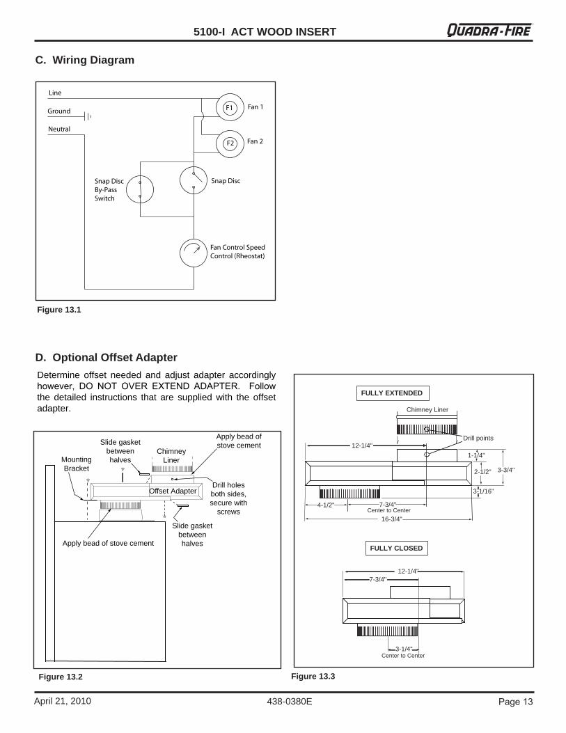
Figure 13.1
C. Wiring Diagram
D. Optional Offset Adapter
FULLY EXTENDED
FULLY CLOSED
3-1/4"
7-3/4"12-1/4"
Center to Center
Chimney Liner
12-1/4"
4-1/2" 7-3/4"
3-1/16"
2-1/2" 3-3/4"
1-1/4"
16-3/4"
Drill points
Center to Center
Slide gasket between halves
Offset Adapter
Chimney LinerMounting
Bracket
Slide gasket between halves
Drill holes both sides, secure with
screws
Apply bead of stove cement
Apply bead of stove cement
Determine offset needed and adjust adapter accordinglyhowever, DO NOT OVER EXTEND ADAPTER. Follow the detailed instructions that are supplied with the offsetadapter.
Figure 13.2 Figure 13.3
5100-I ACT WOOD INSERT
Page 1� April21,2010
R
438-0380E
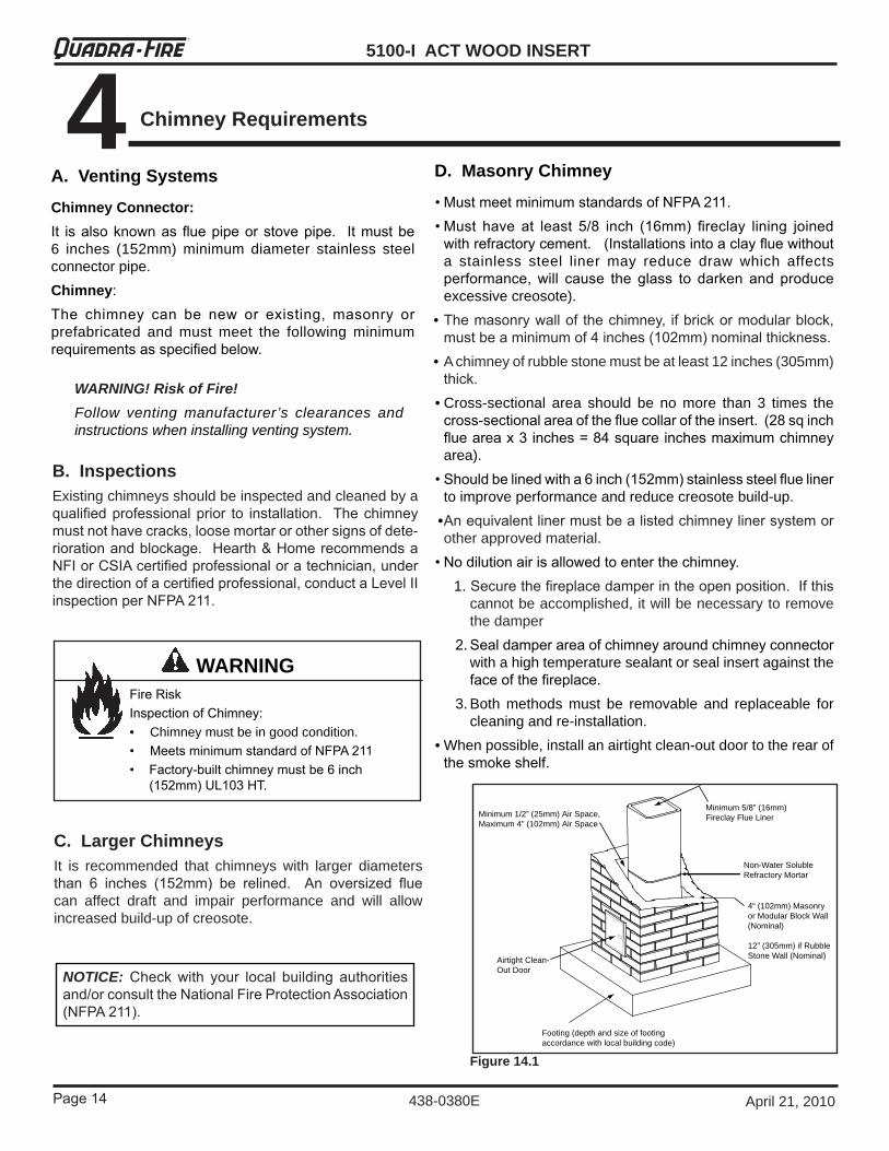
D. Masonry Chimney
• Must meet minimum standards of NFPA �11. • Must have at least 5/8 inch (16mm) fireclay lining joined
with refractory cement. (Installations into a clay flue without a stainless steel liner may reduce draw which affectsperformance, will cause the glass to darken and produce excessivecreosote).
•The masonry wall of the chimney, if brick or modular block, must be a minimum of � inches (10�mm) nominal thickness.
•Achimneyofrubblestonemustbeatleast12inches(305mm)thick.
•Cross-sectional area should be no more than 3 times thecross-sectional area of the flue collar of the insert. (�8 sq inch flue area x � inches = 8� square inches maximum chimney area).
• Should be lined with a 6 inch (15�mm) stainless steel flue liner toimproveperformanceandreducecreosotebuild-up.
• An equivalent liner must be a listed chimney liner system or otherapprovedmaterial.
• No dilution air is allowed to enter the chimney. 1.Secure the fireplace damper in the open position. If this
cannotbeaccomplished,itwillbenecessarytoremovethedamper
�. Seal damper area of chimney around chimney connector withahightemperaturesealantorsealinsertagainsttheface of the fireplace.
3.Both methods must be removable and replaceable forcleaningandre-installation.
•Whenpossible,installanairtightclean-outdoortotherearofthe smoke shelf.
Minimum 1/2” (25mm) Air Space,Maximum 4” (102mm) Air Space
Airtight Clean-Out Door
Minimum 5/8” (16mm) Fireclay Flue Liner
Non-Water Soluble Refractory Mortar
4“ (102mm) Masonry or Modular Block Wall (Nominal)
12” (305mm) if Rubble Stone Wall (Nominal)
Footing (depth and size of footing accordance with local building code)
Figure 14.1
A. Venting Systems
Chimney Connector:It is also known as flue pipe or stove pipe. It must be 6 inches (152mm) minimum diameter stainless steelconnectorpipe.Chimney:The chimney can be new or existing, masonry or prefabricated and must meet the following minimumrequirements as specified below.
WARNING! Risk of Fire!Follow venting manufacturer’s clearances andinstructionswheninstallingventingsystem.
B. InspectionsExistingchimneysshouldbeinspectedandcleanedbyaqualified professional prior to installation. The chimney must not have cracks, loose mortar or other signs of dete-rioration and blockage. Hearth & Home recommends a NFI or CSIA certified professional or a technician, under the direction of a certified professional, conduct a Level II inspection per NFPA �11.
Fire RiskInspection of Chimney:• Chimneymustbeingoodcondition.• Meets minimum standard of NFPA �11• Factory-built chimney must be 6 inch
(15�mm) UL10� HT.
WARNING
NOTICE: Check with your local building authorities and/or consult the National Fire Protection Association (NFPA �11).
C. Larger ChimneysIt is recommended that chimneys with larger diametersthan 6 inches (15�mm) be relined. An oversized flue can affect draft and impair performance and will allowincreasedbuild-upofcreosote.
4 Chimney Requirements
Page 15
5100-I ACT WOOD INSERTR
438-0380EApril21,2010
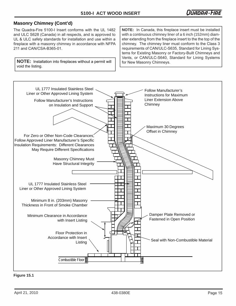
UL 1777 Insulated Stainless Steel Liner or Other Approved Lining System
Follow Manufacturer’s Instructions on Insulation and Support
For Zero or Other Non-Code Clearances, Follow Approved Liner Manufacturer’s Specific Insulation Requirements: Different Clearances
May Require Different Specifications
Masonry Chimney Must Have Structural Integrity
UL 1777 Insulated Stainless Steel Liner or Other Approved Lining System
Minimum 8 in. (203mm) Masonry Thickness in Front of Smoke Chamber
Damper Plate Removed or Fastened in Open Position
Seal with Non-Combustible Material
Minimum Clearance in Accordance with Insert Listing
Floor Protection in Accordance with Insert
Listing
Follow Manufacturer’s Instructions for Maximum Liner Extension Above Chimney
Maximum 30 Degrees Offset in Chimney
Combustible Floor
Masonry Chimney (Cont’d)
Figure 15.1
NOTE: In Canada, this fireplace insert must be installed withacontinuouschimneylinerofa6inch(152mm)diam-eter extending from the fireplace insert to the the top of the chimney. The chimney liner must conform to the Class � requirements of CAN/ULC-S6�5, Standard for Lining Sys-tems for Existing Masonry or Factory-Built Chimneys and Vents, or CAN/ULC-S6�0, Standard for Lining Systems for New Masonry Chimneys.
The Quadra-Fire 5100-I Insert conforms with the UL 1�8� and ULC S6�8 (Canada) in all respects, and is approved to UL & ULC safety standards for installation and use within a fireplace with a masonry chimney in accordance with NFPA �11 and CAN/CSA-B�65-01.
NOTE: Installation into fireplaces without a permit will voidthelisting.
5100-I ACT WOOD INSERT
Page 16 April21,2010
R
438-0380E
F. Prefabricated Metal Chimney
Figure 16.1
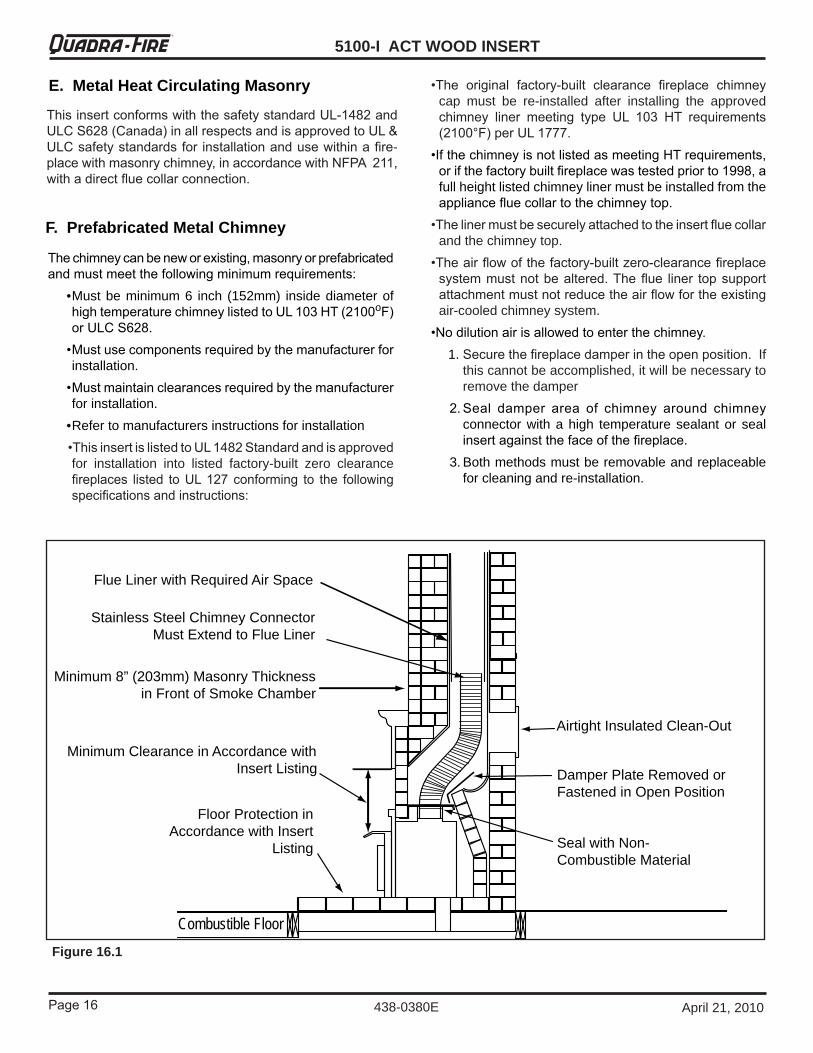
E. Metal Heat Circulating Masonry
The chimney can be new or existing, masonry or prefabricated and must meet the following minimum requirements: •Mustbeminimum6 inch (152mm) insidediameterof
high temperature chimney listed to UL 10� HT (�100oF) or ULC S6�8.
• Must use components required by the manufacturer for installation.
• Must maintain clearances required by the manufacturer forinstallation.
•Refertomanufacturersinstructionsforinstallation •This insert is listed to UL 1�8� Standard and is approved
for installation into listed factory-built zero clearancefireplaces listed to UL 1�7 conforming to the following specifications and instructions:
•The original factory-built clearance fireplace chimney cap must be re-installed after installing the approvedchimney liner meeting type UL 10� HT requirements (�100°F) per UL 1777.
•If the chimney is not listed as meeting HT requirements, or if the factory built fireplace was tested prior to 1998, a fullheightlistedchimneylinermustbeinstalledfromtheappliance flue collar to the chimney top.
•The liner must be securely attached to the insert flue collar andthechimneytop.
•The air flow of the factory-built zero-clearance fireplace system must not be altered. The flue liner top support attachment must not reduce the air flow for the existing air-cooledchimneysystem.
•No dilution air is allowed to enter the chimney. 1.Secure the fireplace damper in the open position. If
thiscannotbeaccomplished,itwillbenecessarytoremovethedamper
�. Seal damper area of chimney around chimney connectorwithahigh temperaturesealantor sealinsert against the face of the fireplace.
3.Bothmethodsmustberemovableandreplaceableforcleaningandre-installation.
Minimum 8” (203mm) Masonry Thickness in Front of Smoke Chamber
Damper Plate Removed or Fastened in Open Position
Seal with Non-Combustible Material
Minimum Clearance in Accordance with Insert Listing
Floor Protection in Accordance with Insert
Listing
Combustible Floor
Airtight Insulated Clean-Out
Stainless Steel Chimney Connector Must Extend to Flue Liner
Flue Liner with Required Air Space
This insert conforms with the safety standard UL-1�8� and ULC S6�8 (Canada) in all respects and is approved to UL & ULC safety standards for installation and use within a fire-place with masonry chimney, in accordance with NFPA �11, with a direct flue collar connection.
Page 17
5100-I ACT WOOD INSERTR
438-0380EApril21,2010
MinimumWidthofCavityOpening 36 914Minimum Height 24 607Minimum Depth from Front to Rear 19 483
Inches Millimeters The following modifications of factory-built fireplaces are permissible:
• The fireplace must not be altered, except that the damper mayberemovedtoaccommodateadirect-connectstarterpipeorchimneyliner,
• Externaltrimpieceswhichdonotaffecttheoperationofthe fireplace may be removed providing they can be stored on or within the fireplace for reassembly if the insert is removed.
• The permanent metal warning label provided must be attached to the back of the fireplace, with screws or nails, stating that the fireplace may have been altered to accommodatetheinsert,andmustbereturnedtooriginalcondition for use as a conventional fireplace. Figure 17.2.
• If the hearth extension is lower than the fireplace opening, theportionoftheinsertextendingontothehearthmustbesupported.
• Manufacturer designed adjustable support kit can be orderedfromyourdealer.
• Final approval of this installation type is contingent upon theauthorityhavingjurisdiction.
Damper Smoke Shelf or BaffleEmberCatches Fire GrateViewing Screen/Curtain Doors
Thefollowingpartsmayberemoved:
Fire Risk.
When lining air-cooled factory-built chimneys:.• Run chimney liner approved to UL 1777 Type
HT requirements (�100 degrees F)• Re-installoriginalfactorybuiltchimneycap
ONLY• DO NOT block cooling air openings in chimney• Blocking cooling air will overheat the chimney
WARNING
Prefabricated Metal Chimney (Cont’d)
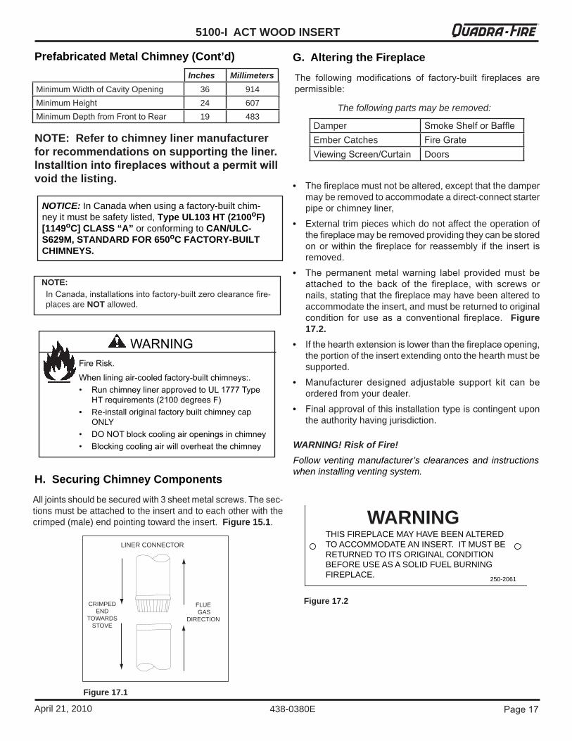
LINER CONNECTOR
FLUE GAS
DIRECTION
CRIMPEDEND
TOWARDS STOVE
Figure 17.1
NOTE:In Canada, installations into factory-built zero clearance fire-placesareNOTallowed.
NOTICE:InCanadawhenusingafactory-builtchim-neyitmustbesafetylisted, Type UL103 HT (2100oF) [1149oC] CLASS “A” orconformingtoCAN/ULC-S629M, STANDARD FOR 650oC FACTORY-BUILT CHIMNEYS.
NOTE: Refer to chimney liner manufacturer for recommendations on supporting the liner. Installtion into fireplaces without a permit will void the listing.
G. Altering the Fireplace
H. Securing Chimney Components
All joints should be secured with � sheet metal screws. The sec-tionsmustbeattachedtotheinsertandtoeachotherwiththecrimped(male)endpointingtowardtheinsert.Figure 15.1.
WARNING! Risk of Fire!Followventingmanufacturer’sclearancesand instructionswheninstallingventingsystem.
250-2061
WARNINGTHIS FIREPLACE MAY HAVE BEEN ALTEREDTO ACCOMMODATE AN INSERT. IT MUST BE RETURNED TO ITS ORIGINAL CONDITION BEFORE USE AS A SOLID FUEL BURNING FIREPLACE. 250-2061
Figure 17.2
5100-I ACT WOOD INSERT
Page 18 April21,2010
R
438-0380E
Ovalizingroundstainlesssteel linerstoaccommodatetheliner passing through the damper region of a fireplace is an allowableandacceptablepractice.Ensure that the ovalization is minimized to the extentrequired to fit through the damper.
I. Ovalizing Round Stainless Steel Liners
Fire Risk.Do NOT pack insulation or other combustibles betweenspacers.
• ALWAYS maintain specified clearances around ventingandspacers.
• Install spacers as specified.
Failure to keep insulation or other material away fromvent pipe may cause fire.
WARNING
WARNING! Risk of Asphyxiation!• DoNoTcoNNecTThisappliaNceTo
achimNeyFlueserviciNgaNoTherappliaNceorToaNyairDisTribuTioNDucTorsysTem.
This may allow flue gases to enter the house.
J. Chimney Height / Rise and RunTo be sure that your Quadra-Fire insert burns properly, the chimneydraft(staticpressure)shouldbeapproximately-0.10inches water column (W.C.) during a high burn and -0.04inchesW.C.duringalowburn,measured6inches(152mm)abovethetopoftheinsertafteronehourofoperationateachburnsetting.
NOTE: These are guidelines only, and may vary somewhat forindividualinstallations.
• This product was designed for and tested on a 6 inch (152mm) chimney, 14 to 16 feet (4.27-4.87m) high, (in-cludesapplianceheight)measured fromthebaseof theappliance.
• The further your stack height or diameter varies from this configuration, the possibility of performance problems ex-ists.
• Chimneyheightmayneedtobeincreasedby2-3%pereach1000feet(304.8m)abovesealevel.
• Itisnotrecommendedtouseoffsetsorelbowsataltitudesabove4000feet(1219.2m)abovesealevelorwhenthereare other factors that affect flue draft.
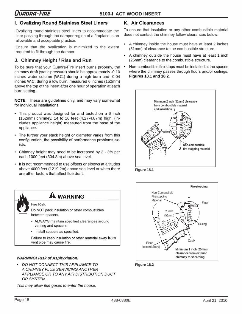
Floor
Ceiling
CaulkFloor(second Story)
Non-CombustibleFirestoppingMaterial
Minimum 1 inch (25mm) clearance from exterior chimney to sheathing
Firestopping
2inch(51mm)
Non-combustiblefire stopping material
Minimum 2 inch (51mm) clearancefrom combustible materialand insulation
ceiling
K. Air Clearances
Figure 18.1
Figure 18.2
To ensure that insulation or any other combustible material does not contact the chimney follow clearances below:
• Achimneyinsidethehousemusthaveatleast2inches(51mm)ofclearancetothecombustiblestructure.
• Achimneyoutside thehousemusthaveat least1 inch(25mm)clearancetothecombustiblestructure.
• Non-combustible fire stops must be installed at the spaces where the chimney passes through floors and/or ceilings. Figures 18.1 and 18.2.
Page 19
5100-I ACT WOOD INSERTR
438-0380EApril21,2010
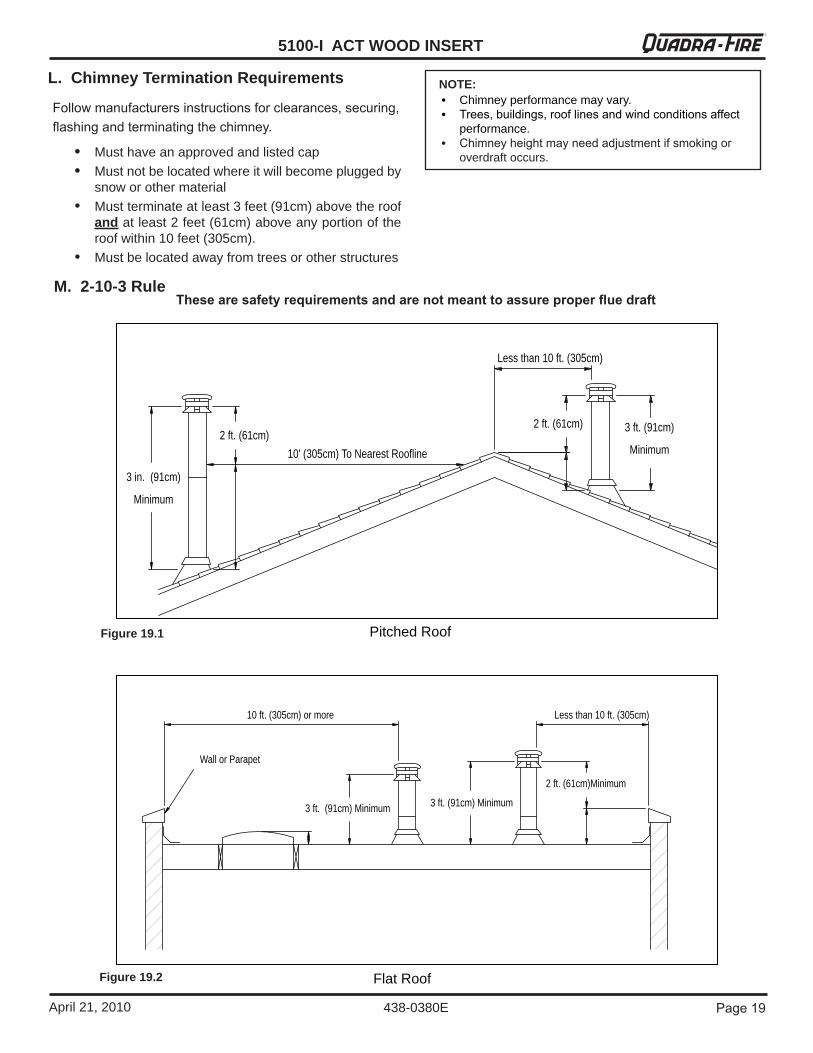
L. Chimney Termination Requirements
Follow manufacturers instructions for clearances, securing, flashing and terminating the chimney.
• Musthaveanapprovedandlistedcap • Mustnotbelocatedwhereitwillbecomepluggedby
snoworothermaterial • Mustterminateatleast3feet(91cm)abovetheroof
andatleast2feet(61cm)aboveanyportionoftheroofwithin10feet(305cm).
• Mustbelocatedawayfromtreesorotherstructures
These are safety requirements and are not meant to assure proper flue draft
NOTE:• Chimneyperformancemayvary.• Trees, buildings, roof lines and wind conditions affect
performance.• Chimney height may need adjustment if smoking or
overdraftoccurs.
M. 2-10-3 Rule
10 ft. (305cm) or more
3 ft. (91cm) Minimum
Less than 10 ft. (305cm)
2 ft. (61cm)Minimum
3 ft. (91cm) Minimum
Wall or Parapet
3 in. (91cm)
Minimum
Less than 10 ft. (305cm)
2 ft. (61cm) 3 ft. (91cm)
Minimum10' (305cm) To Nearest Roofline2 ft. (61cm)
Flat Roof
Pitched Roof
Figure 19.2
Figure 19.1
5100-I ACT WOOD INSERT
Page �0 April21,2010
R
438-0380E
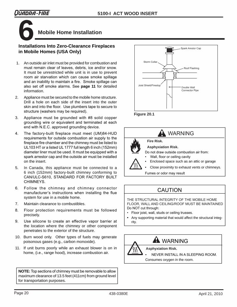
Spark ArestorCap
Roof Flashing
Storm Collar
Joist Shield/Firestop DoubleWallConnector Pipe
Figure 20.1
CAUTIONTHE STRUCTURAL INTEGRITY OF THE MOBILE HOME FLOOR, WALL AND CEILING/ROOF MUST BE MAINTAINEDDo NOT cut through:• Floor joist, wall, studs or ceiling trusses.• Anysupportingmaterialthatwouldaffectthestructuralinteg-
rity.
• NEVER INSTALL IN A SLEEPING ROOM.Consumesoxygenintheroom.
WARNINGAsphyxiation Risk.
WARNING
Do not draw outside combustion air from:• Wall, floor or ceiling cavity• Enclosedspacesuchasanatticorgarage
• Closeproximitytoexhaustventsorchimneys.
Fumes or odor may result
Fire Risk.Asphyxiation Risk.
1. Anoutsideairinletmustbeprovidedforcombustionandmust remain clear of leaves, debris, ice and/or snow. Itmustbeunrestrictedwhileunit is inusetopreventroom air starvation which can cause smoke spillage and an inability to maintain a fire. Smoke spillage can also set off smoke alarms. See page 11 fordetailedinformation.
2. Appliancemustbesecuredtothemobilehomestructure.Drill a hole on each side of the insert into the outerskin and into the floor. Use plumbers tape to secure to structure (washers may be required).
�. Appliance must be grounded with #8 solid copper grounding wire or equivalent and terminated at each end with N.E.C. approved grounding device.
�. The factory-built fireplace must meet (UM)8�-HUD requirements for outside combustion air supply to the fireplace fire chamber and the chimney must be listed to UL10� HT or a listed UL 1777 full length 6 inch (15�mm) diameter liner must be used. It must be equipped with a spark arrestor cap and the outside air must be installed ontheinsert.
5. In Canada, this appliance must be connected to a6 inch (152mm) factory-built chimney conforming toCAN/ULC-S610, STANDARD FOR FACTORY BUILT CHIMNEYS.
6. Fol low the chimney and chimney connector manufacturer’s instructions when installing the flue systemforuseinamobilehome.
7. Maintainclearancetocombustibles.8. Floor protection requirements must be followed
precisely.9. Use silicone to create an effective vapor barrier at
the location where the chimney or other componentpenetratestotheexteriorofthestructure.
10. Burn wood only. Other types of fuels may generatepoisonousgases(e.g.,carbonmonoxide).
11. If unit burns poorly while an exhaust blower is on inhome,(i.e.,rangehood),increasecombustionair.
NOTE: Top sections of chimney must be removable to allow maximumclearanceof13.5feet(411cm)fromgroundlevelfortransportationpurposes.
Installations Into Zero-Clearance Fireplaces in Mobile Homes (USA Only)
6 Mobile Home Installation
Page �1
5100-I ACT WOOD INSERTR
438-0380EApril21,2010
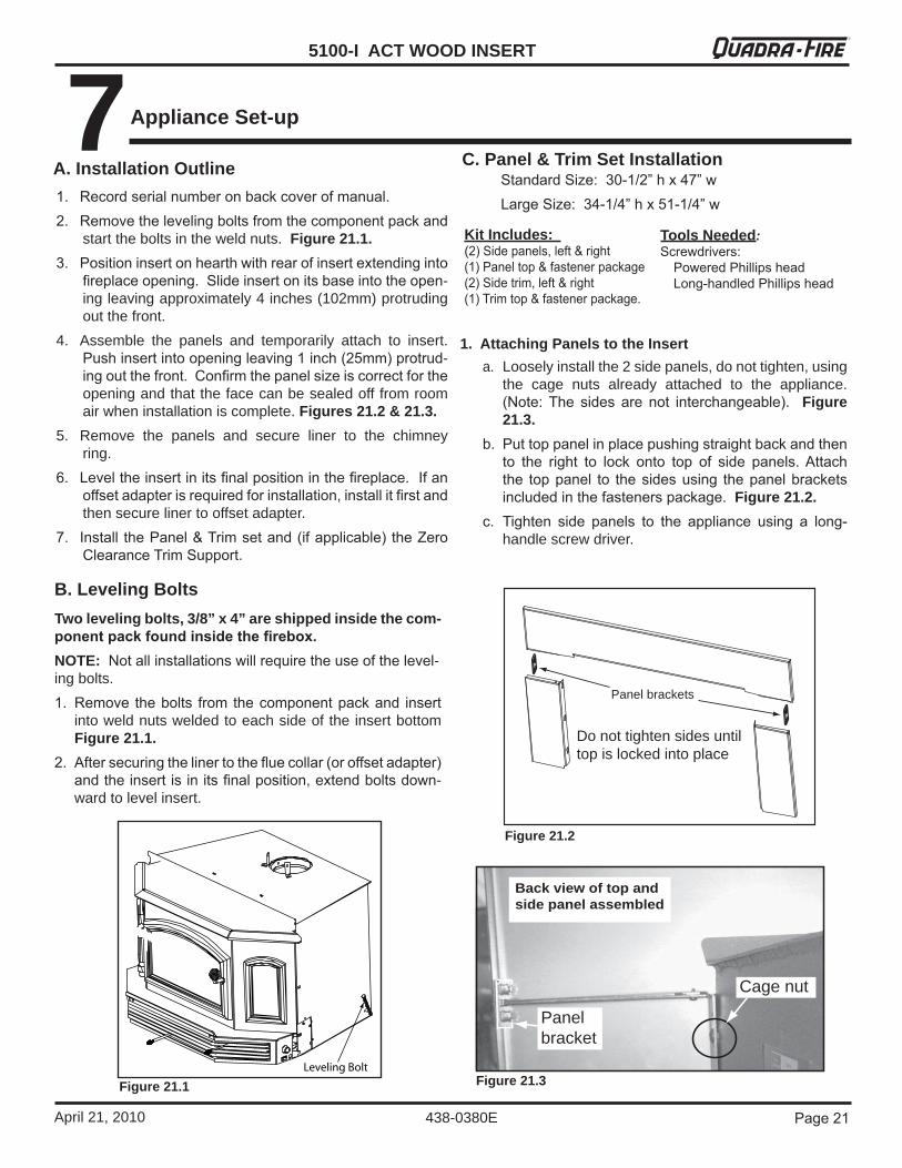
Figure 21.1
Figure 21.2
Figure 21.3
Two leveling bolts, 3/8” x 4” are shipped inside the com-ponent pack found inside the firebox. NOTE: Not all installations will require the use of the level-ingbolts.1. Remove the bolts from the component pack and insert
intoweldnutsweldedtoeachsideoftheinsertbottom Figure 21.1.
�. After securing the liner to the flue collar (or offset adapter) and the insert is in its final position, extend bolts down-wardtolevelinsert.
B. Leveling Bolts
7Appliance Set-up
Standard Size: �0-1/�” h x �7” wLarge Size: ��-1/�” h x 51-1/�” w
Do not tighten sides until top is locked into place
Panel brackets
a. Looselyinstallthe2sidepanels,donottighten,usingthe cage nuts already attached to the appliance.(Note: The sides are not interchangeable). Figure 21.3.
b. Put top panel in place pushing straight back and then to the right to lock onto top of side panels. Attach the top panel to the sides using the panel brackets included in the fasteners package. Figure 21.2.
c. Tighten side panels to the appliance using a long-handlescrewdriver.
Back view of top and side panel assembled
Panel bracket
Cage nut
1. Attaching Panels to the Insert
C. Panel & Trim Set Installation
Kit Includes: (�) Side panels, left & right (1) Panel top & fastener package (�) Side trim, left & right (1) Trim top & fastener package.
Tools Needed:Screwdrivers:
Powered Phillips head Long-handled Phillips head
A. Installation Outline1. Record serial number on back cover of manual. �. Remove the leveling bolts from the component pack and
starttheboltsintheweldnuts. Figure 21.1.�. Position insert on hearth with rear of insert extending into
fireplace opening. Slide insert on its base into the open-ingleavingapproximately4inches(102mm)protrudingoutthefront.
4. Assemble the panels and temporarily attach to insert.Push insert into opening leaving 1 inch (�5mm) protrud-ing out the front. Confirm the panel size is correct for the openingandthatthefacecanbesealedofffromroomairwheninstallationiscomplete. Figures 21.2 & 21.3.
5. Remove the panels and secure liner to the chimneyring.
6. Level the insert in its final position in the fireplace. If an offset adapter is required for installation, install it first and thensecurelinertooffsetadapter.
7. Install the Panel & Trim set and (if applicable) the Zero Clearance Trim Support.
5100-I ACT WOOD INSERT
Page �� April21,2010
R
438-0380E
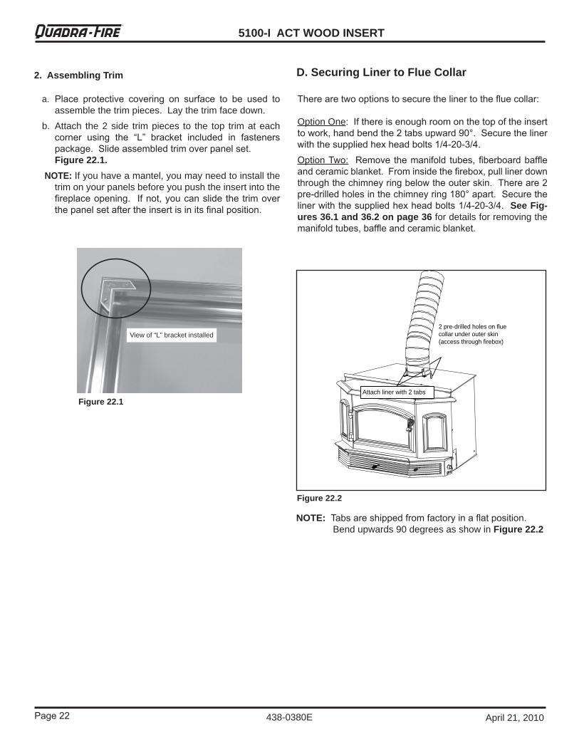
Figure 22.1
Figure 22.2
There are two options to secure the liner to the flue collar:
OptionOne: If there is enough room on the top of the insert to work, hand bend the � tabs upward 90°. Secure the liner with the supplied hex head bolts 1/�-�0-�/�.Option Two: Remove the manifold tubes, fiberboard baffle and ceramic blanket. From inside the firebox, pull liner down through the chimney ring below the outer skin. There are � pre-drilled holes in the chimney ring 180° apart. Secure the liner with the supplied hex head bolts 1/�-�0-�/�. See Fig-ures 36.1 and 36.2 on page 36fordetailsforremovingthemanifold tubes, baffle and ceramic blanket.
NOTE: Tabs are shipped from factory in a flat position. Bendupwards90degreesasshowinFigure 22.2
2 pre-drilled holes on flue collar under outer skin (access through firebox)
Attach liner with 2 tabs
a. Place protective covering on surface to be used to assemblethetrimpieces.Laythetrimfacedown.
b. Attach the2side trimpieces to the top trimateachcorner using the “L” bracket included in fasteners package. Slide assembled trim over panel set.Figure 22.1.
NOTE: Ifyouhaveamantel,youmayneedtoinstallthetrimonyourpanelsbeforeyoupushtheinsertintothefireplace opening. If not, you can slide the trim over the panel set after the insert is in its final position.
2. Assembling Trim
View of “L” bracket installed
D. Securing Liner to Flue Collar
Page ��
5100-I ACT WOOD INSERTR
438-0380EApril21,2010
Figure 23.1
Figure 23.2
Figure 23.3
Figure 23.4
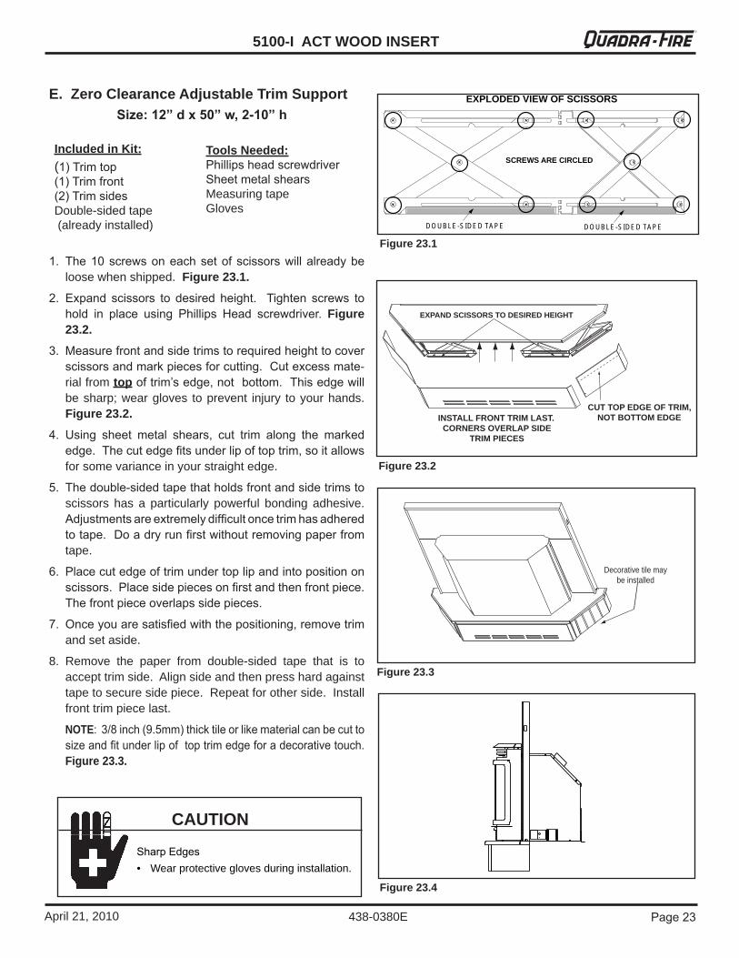
E. Zero Clearance Adjustable Trim SupportSize: 12” d x 50” w, 2-10” h
1. The 10 screws on each set of scissors will already be loosewhenshipped.Figure 23.1.
�. Expand scissors to desired height. Tighten screws to hold in place using Phillips Head screwdriver. Figure 23.2.
�. Measure front and side trims to required height to cover scissors and mark pieces for cutting. Cut excess mate-rialfromtop of trim’s edge, not bottom. This edge will besharp;weargloves toprevent injury toyourhands. Figure 23.2.
�. Using sheet metal shears, cut trim along the marked edge. The cut edge fits under lip of top trim, so it allows forsomevarianceinyourstraightedge.
5. The double-sided tape that holds front and side trims to scissors has a particularly powerful bonding adhesive.Adjustments are extremely difficult once trim has adhered to tape. Do a dry run first without removing paper from tape.
6. Place cut edge of trim under top lip and into position on scissors. Place side pieces on first and then front piece. The front piece overlaps side pieces.
7. Once you are satisfied with the positioning, remove trim andsetaside.
8. Remove the paper from double-sided tape that is toaccepttrimside.Alignsideandthenpresshardagainsttapetosecuresidepiece.Repeatforotherside.Installfronttrimpiecelast.
NOTE: �/8 inch (9.5mm) thick tile or like material can be cut to size and fit under lip of top trim edge for a decorative touch. Figure 23.3.
Included in Kit: (1) Trim top(1) Trim front(�) Trim sidesDouble-sidedtape(alreadyinstalled)
Tools Needed:Phillips head screwdriverSheet metal shearsMeasuringtapeGloves
INSTALL FRONT TRIM LAST.CORNERS OVERLAP SIDE
TRIM PIECES
EXPAND SCISSORS TO DESIRED HEIGHT
CUT TOP EDGE OF TRIM, NOT BOTTOM EDGE
Decorative tile may be installed
CAUTION
Sharp Edges• Wearprotectiveglovesduringinstallation.
D O U B L E -S ID E D TA P E D O U B L E -S ID E D TA P E
SCREWS ARE CIRCLED
EXPLODED VIEW OF SCISSORS

5100-I ACT WOOD INSERT
Page �� April21,2010
R
438-0380E
B. Wood Selection & Storage
Burn only dry seasoned wood. Store wood under cover, out oftherainandsnow.Dryandwell-seasonedwoodwillnotonlyminimizethechanceofcreosoteformation,butwillgiveyou the most efficient fire. Even dry wood contains at least
C. Burning ProcessInrecentyearstherehasbeenanincreasingconcernaboutair quality. Much of the blame for poor air quality has been placedontheburningofwoodforhomeheating.Inordertoimprove the situation, we at Quadra-Fire have developed cleaner-burning woodstoves that surpass the requirements for emissions established by our governing agencies. These woodstoves, like any other appliances, must be properly operatedinordertoinsurethattheyperformthewaytheyaredesignedtoperform.Improperoperationcanturnmostanywoodstoveintoasmolderingenvironmentalhazard.
1. Kindling or First StageIt helps to know a little about the actual process of burning in order to understand what goes on inside a stove. The first stage of burning is called the kindling stage. In this stage, the woodisheatedtoatemperaturehighenoughtoevaporatethemoisture which is present in all wood. The wood will reach the boiling point of water (�1�°F) and will not get any hotter until the water is evaporated. This process takes heat from thecoalsandtendstocooltheappliance.Fire requires three things to burn - fuel, air and heat. So, if heatisrobbedfromtheapplianceduringthedryingstage,thenewloadofwoodhasreducedthechancesforagoodclean burn. For this reason, it is always best to burn dry, seasoned firewood. When the wood isn’t dry, you must opentheaircontrolsandburnatahighburnsettingforalonger time to start it burning. The heat generated from the fire should be warming your home and establishing the flue draft,notevaporatingthemoistureoutofwet,unseasonedwood,resultinginwastedheat.
Do not over-fire.
Over-firing may ignite creosote or will damage thestoveandchimney.
To prevent over-firing your stove, DO NOT:
• Use flammable liquids• Overloadwithwood• Burntrashorlargeamountsofscraplumber• Permit too much air to the fire
WARNINGFire Risk
Symptoms of over-firing may include one or more of the following: • Chimneyconnectororapplianceglowing • Roaring,rumblingnoises • Loud cracking or banging sounds • Metalwarping • Chimney fire
1. Symptoms of Over-Firing
2. What To Do if Your Stove is Over-Firing
• Immediatelyclosethedoorandaircontrolstoreduceair supply to the fire.
• If you suspect a chimney fire, call the fire department andevacuateyourhouse.
• Contactyourlocalchimneyprofessionalandhaveyourstoveandstovepipeinspectedforanydamage.
• Donotuseyourstoveuntil thechimneyprofessionalinformsyouitissafetodoso.
Hearth & Home Technologies WILL NOT warranty stoves that exhibit evidence of over-firing. Evidence of over-firing includes, but is not limited to: • Warpedairtube • Deteriorated refractory brick retainers • Deteriorated baffle and other interior components
A. Over-Firing Your Appliance
15%moisturebyweight,andshouldbeburnedhotenoughtokeep the chimney hot for as long as it takes to dry the wood out -aboutonehour.Itisawasteofenergytoburnunseasonedwood of any kind.Dead wood lying on the forest floor should be considered wet, and requires full seasoning time. Standing dead wood can be considered to be about �/� seasoned. To tell if wood is dry enough to burn, check the ends of the logs. If there are cracks radiating in all directions from the center, it is dry. If your wood sizzles in the fire, even though the surface is dry, itmaynotbefullycured.Splitting wood before it is stored reduces drying time. Wood should be stacked so that both ends of each piece are exposed toair,sincemoredryingoccursthroughthecutendsthanthesides. This is true even with wood that has been split. Store woodundercover,suchasinashed,orcoveredwithatarp,plastic, tarpaper,sheetsofscrapplywood,etc.,asuncov-eredwoodcanabsorbwaterfromrainorsnow,delayingtheseasoningprocess.
8 Operating Instructions
Page �5
5100-I ACT WOOD INSERTR
438-0380EApril21,2010
2. Second StageThe next stage of burning, the secondary stage, is the period when the wood gives off flammable gases which burn above the fuel with bright flames. During this stage of burning it is very important that the flames be maintained and not allowed to go out. This will ensure the cleanest possible fire. If the flames tend to go out, it is set too low for your burning condi-tions. The air control located at the upper right hand corner is used to adjust for burn rates. This is called the BurnRateAirControl.Figure 21.1.3. Final StageThe final stage of burning is the charcoal stage. This occurs when the flammable gases have been mostly burned and only charcoal remains. This is a naturally clean portion of the burn. The coals burn with hot blue flames. It isvery important to reloadyourappliancewhileenoughlivelyhotcoalsremaininordertoprovidetheamountofheatneeded to dry and rekindle the next load of wood. It is best to open the Burn Rate Air and Start-Up Air Controls before reloading. This livens up the coalbed and reduces excessive emissions (opacity/smoke). Open door slowly so that ash or smoke does not exit appliance through opening. You should also break up any large chunks and distribute the coals so thatthenewwoodislaidonhotcoals.Air quality is important to all of us, and if we choose to use wood to heat our homes we should do so responsibly. To do thisweneedtolearntoburnourstovesinthecleanestwaypossible.Doingthiswillallowustocontinueusingourwoodstovesformanyyearstocome.
Before lighting your first fire in the insert, make certain that the baffle is correctly positioned. It should be resting against therearsupport.Refertopage 28.
NOTE: Removealllabelsfromglassfrontpriortolightingthe first fire and refer to plated surfaces care on page 31.
There are many ways to build a fire. The basic principle istolighteasily-ignitabletinderorpaper,whichignitesthefast burning kindling, which in turn ignites the slow-burning firewood. Here is one method that works well:
1. Place several wads of crushed paper on the firebox floor. Heating flue with slightly crumpled newspaper before addingkindlingkeepssmoketoaminimum.
�. Place several wads of crushed paper on the firebox floor.
D. Building A Fire
3. Open Start-Up Air Control (right control) and Primary Air Control(centercontrolunderashlip)fully.Figure 23.1 on page 23.
4. Ensurethatnomatchesorothercombustiblesareintheimmediate area of the insert, that the room is adequately ventilated, and the flue is unobstructed.
5. Light the paper in the insert. NEVER light or rekindle insert with kerosene, gasoline, or charcoal lighter fluid; the results canbefatal.
6. Once the kindling is burning quickly, add several full-length logs3inches(76mm)or4inches(102mm)indiameter.Becareful not to smother the fire. Stack the pieces of wood carefully: near enough to keep each other hot, but far enough away from each other to allow adequate air flow betweenthem.
7. Whenreadytoreloadtheinsert,addmorelogs.Largelogsburn slowly, holding a fire longer. Small logs burn fast and hot, giving quick heat.
8. Adjust the Start-Up Air Control and Primary Air Control, maintaining flames above the fuel. The more you close down the Primary Control, the lower and slower the fire will burn. The more you open the Primary Control the more heat will be produced. The Start-Up Air Control (right control) is only used for the first 5 to 15 minutes.
Aslongastherearehotcoals,repeatingsteps7and8willmaintain a continuous fire.
Fire Risk.Keepcombustiblematerials,gasolineandotherflammable vapors and liquids clear of appliance.• Do NOT store flammable materials in the
appliance’s vicinity.• DO NOT USE GASOLINE, LANTERN FUEL,
kEROSENE, CHARCOAL LIGHTER FLUID OR SIMILAR LIQUIDS TO START OR “FRESHEN UP” A FIRE IN THIS HEATER.
• keep all such liquids well away from the heaterwhileitisinuse.
• Combustiblematerialsmayignite.
WARNING
WARNINGFire Risk.• DO NOT BURN GARBAGE OR FLAMMABLE
FLUIDS SUCH AS GASOLINE, NAPTHA OR ENGINE OIL.
• Do NOT burn treated wood or wood with salt (driftwood).• Maygeneratecarbonmonoxideifburnmaterialotherthan
wood.Mayresultinillnessorpossibledeath.
WARNINGFire Risk.• Do NOT burn with insert door open.
Embers may fall out and start a fire.
5100-I ACT WOOD INSERT
Page �6 April21,2010
R
438-0380E
Odorsandvaporsreleasedduringinitialoperation.• Curingofhightemperaturepaint.• Openwindowsforaircirculation.
Odorsmaybeirritatingtosensitiveindividuals.
CAUTION
For maximum operating efficiency with the lowest emissions, follow these operating procedures:
1. Regardlessofdesiredheatoutput,whenloadinginsert,burn your Quadra-Fire with both air controls wide open for aminimumof5to15minutes.
�. Regulate burn rate (heat output) by using the Primary Con-trol (center control under ashlip). The Start-Up Air Control (rightcontrol)ismainlyforinitialstart-upandreloading.
�. Heat output settings: Follow burn rate instructions listed below.
4. Burn only dry, well-seasoned wood.
Theseareapproximatesettings,andwillvarywithtypeofwoodorchimneydraft.
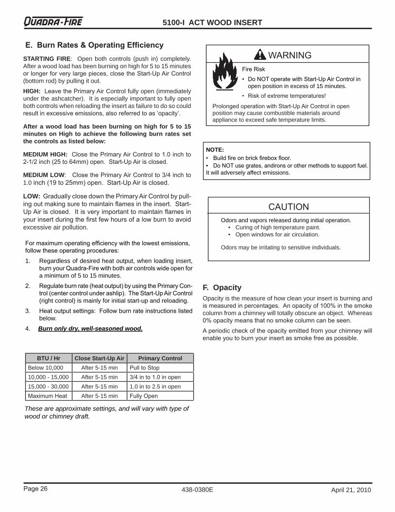
E. Burn Rates & Operating EfficiencySTARTING FIRE: Openbothcontrols (push in) completely.Afterawoodloadhasbeenburningonhighfor5to15minutesor longer for very large pieces, close the Start-Up Air Control (bottomrod)bypullingitout.
HIGH: Leave the PrimaryAirControlfullyopen(immediatelyundertheashcatcher).Itisespeciallyimportanttofullyopenbothcontrolswhenreloadingtheinsertasfailuretodosocouldresult in excessive emissions, also referred to as ‘opacity’.
After a wood load has been burning on high for 5 to 15 minutes on High to achieve the following burn rates set the controls as listed below:
MEDIUM HIGH: Close the Primary Air Control to 1.0 inch to �-1/� inch (�5 to 6�mm) open. Start-Up Air is closed.
MEDIUM LOW: Close the Primary Air Control to �/� inch to 1.0inch (19 to �5mm) open. Start-Up Air is closed.
LOW: Gradually close down the Primary Air Control by pull-ing out making sure to maintain flames in the insert. Start-Up Air is closed. It is very important to maintain flames in your insert during the first few hours of a low burn to avoid excessiveairpollution.
F. OpacityOpacityisthemeasureofhowcleanyourinsertisburningandis measured in percentages. An opacity of 100% in the smoke columnfromachimneywilltotallyobscureanobject.Whereas0% opacity means that no smoke column can be seen.
A periodic check of the opacity emitted from your chimney will enable you to burn your insert as smoke free as possible.
BTU / Hr Close Start-Up Air Primary ControlBelow10,000 After5-15min Pull to Stop10,000-15,000 After5-15min �/� in to 1.0 in open15,000-30,000 After5-15min 1.0into2.5inopenMaximum Heat After5-15min Fully Open
NOTE:• Build fire on brick firebox floor.• Do NOT use grates, andirons or other methods to support fuel.Itwilladverselyaffectemissions.
Fire Risk
• Do NOT operate with Start-Up Air Control in openpositioninexcessof15minutes.
• Risk of extreme temperatures!
WARNING
Prolonged operation with Start-Up Air Control in open positionmaycausecombustiblematerialsaroundappliancetoexceedsafetemperaturelimits.
Page �7
5100-I ACT WOOD INSERTR
438-0380EApril21,2010
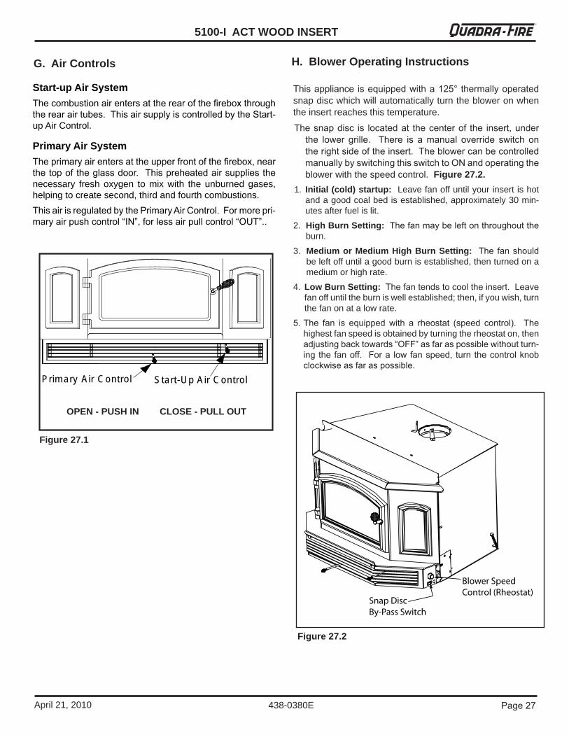
This appliance is equipped with a 1�5° thermally operated snapdiscwhichwillautomaticallyturnthebloweronwhentheinsertreachesthistemperature.
The snap disc is located at the center of the insert, under the lower grille. There is a manual override switch on the right side of the insert. The blower can be controlled manually by switching this switch to ON and operating the blowerwiththespeedcontrol.Figure 27.2.
1. Initial (cold) startup:Leavefanoffuntilyourinsertishotandagoodcoalbedisestablished,approximately30min-utesafterfuelislit.
2. High Burn Setting: The fan may be left on throughout the burn.
3. Medium or Medium High Burn Setting: The fan should beleftoffuntilagoodburnisestablished,thenturnedonamediumorhighrate.
4. Low Burn Setting: The fan tends to cool the insert. Leave fanoffuntiltheburniswellestablished;then,ifyouwish,turnthefanonatalowrate.
5. The fan is equipped with a rheostat (speed control). The highestfanspeedisobtainedbyturningtherheostaton,thenadjusting back towards “OFF” as far as possible without turn-ing the fan off. For a low fan speed, turn the control knob clockwise as far as possible.
H. Blower Operating Instructions
Figure 27.1
Start-up Air SystemThe combustion air enters at the rear of the firebox through the rear air tubes. This air supply is controlled by the Start-upAirControl.
Primary Air SystemThe primary air enters at the upper front of the firebox, near the top of the glass door. This preheated air supplies the necessary fresh oxygen to mix with the unburned gases,helpingtocreatesecond,thirdandfourthcombustions.This air is regulated by the Primary Air Control. For more pri-mary air push control “IN”, for less air pull control “OUT”..
G. Air Controls
Prim ary Air C ontrol Start-U p Air C ontrol
OPEN - PUSH IN CLOSE - PULL OUT
Figure 27.2
5100-I ACT WOOD INSERT
Page �8 April21,2010
R
438-0380E
CORRECT POSITION
INCORRECT POSITIONS
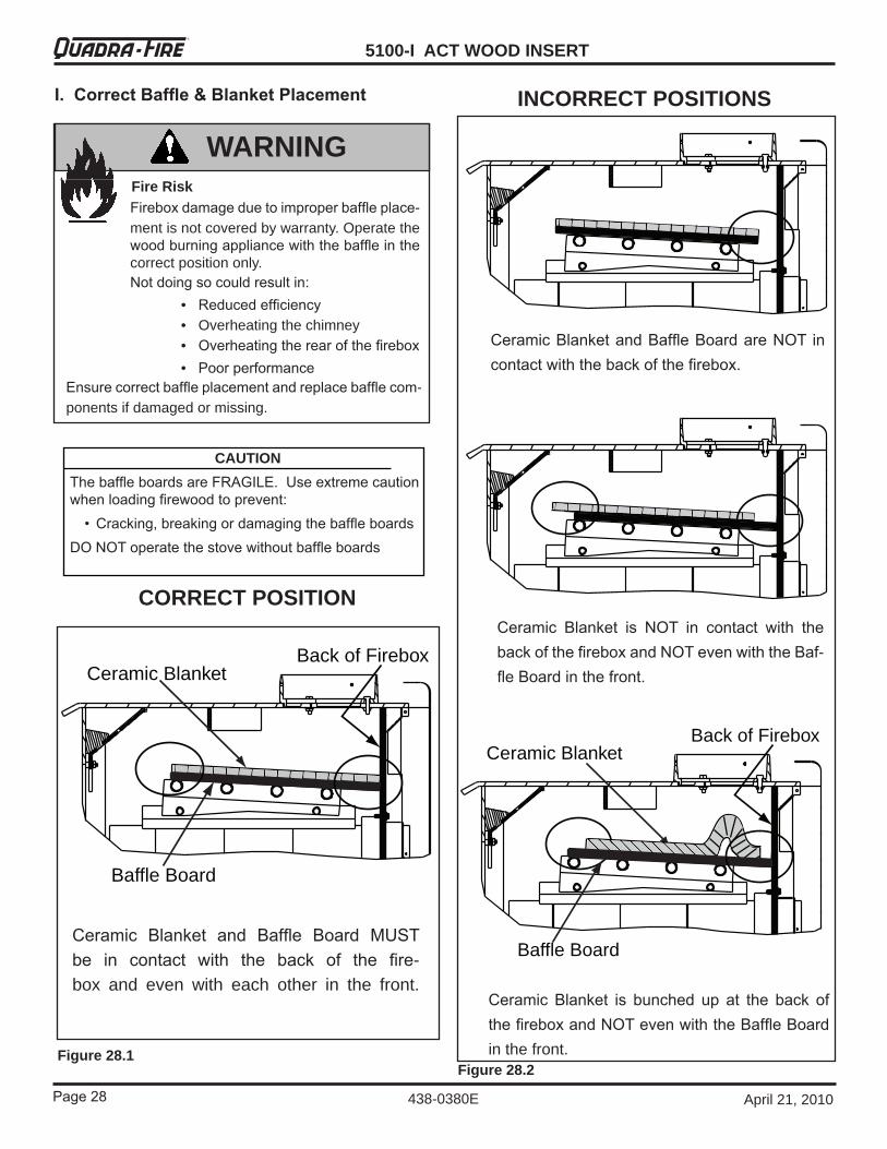
Firebox damage due to improper baffle place-mentisnotcoveredbywarranty.Operatethewood burning appliance with the baffle in the correctpositiononly.Not doing so could result in:
• Reduced efficiency • Overheatingthechimney • Overheating the rear of the firebox
• Poor performance
WARNINGFire Risk
Ensure correct baffle placement and replace baffle com-ponentsifdamagedormissing.
I. Correct Baffle & Blanket Placement
Ceramic Blanket and Baffle Board are NOT in contact with the back of the firebox.
Ceramic Blanket is NOT in contact with the back of the firebox and NOT even with the Baf-fle Board in the front.
Ceramic Blanket is bunched up at the back of the firebox and NOT even with the Baffle Board inthefront.
Ceramic BlanketBack of Firebox
Baffle Board
Figure 28.2Figure 28.1
Ceramic Blanket and Baffle Board MUST be in contact with the back of the fire-box and even with each other in the front.
Ceramic BlanketBack of Firebox
Baffle Board
CAUTIONThe baffle boards are FRAGILE. Use extreme caution when loading firewood to prevent: • Cracking, breaking or damaging the baffle boardsDO NOT operate the stove without baffle boards
Page �9
5100-I ACT WOOD INSERTR
438-0380EApril21,2010
Odorsandvaporsarereleasedduringinitialoperation.• Curingofhightemperaturepaint.• Openwindowsforaircirculation.
Odorsmaybeirritatingtosensitiveindividuals.
CAUTION
J. Frequently Asked Questions
ISSUES SOLUTIONSOdorfromappliance When first operated, this appliance may release an odor for the first several
hours. This is caused by the curing of the paint and the burning off of any oils remainingfrommanufacturing.
Metallicnoise Noise is caused by metal expanding and contracting as it heats up and cools down, similar to the sound produced by a furnace or heating duct. This noise doesnotaffecttheoperationorlongevityoftheappliance.
Whirringsound The blower produces a whirring sound which increases in volume as the speed isincreased.
5100-I ACT WOOD INSERT
Page �0 April21,2010
R
438-0380E
9 Maintaining & Servicing Your Appliance
A. General Maintenance
Inspection:Inspectthesystemattheapplianceconnectionandatthechimneytop.Coolersurfacestendtobuildcreosotedeposits quicker, so it is important to check the chimney from thetopaswellasfromthebottom.Formation and Need For Removal: When wood is burned slowly, it produces tar and other organic vapors whichcombinewithexpelledmoisturetoformcreosote.The creosote vapors condense in the relatively cool chimney flue of a newly-started or a slow-burning fire. As a result, creosote residue accumulates on the flue lining. When
1. Creosote (Chimney) Cleaning
• Frequency: Every2monthsduringheatingseasonorasrecommendedbyacertifiedchimneysweep;morefrequently if chimney exceeds or is under 1�-16 ft (�.�7 to4.87m)measuredfrombottomofappliance.
• By: Homeowner / Chimney Sweep• Task: Remove all ash from the firebox and extinguish
allhotembersbeforedisposal.Allowtheappliancetocoolcompletely.Ifthechimneyhasafullreline,removethe baffle, ceramic blanket and manifold tubes from the insert before cleaning chimney. Otherwise residuecan pile up on top of the baffle and the appliance will not work properly. (See Baffle Removal on page 32).Close the door tightly. The creosote or soot should be removed with a brush specifically designed for the typeofchimneyinuse.Cleanoutfallenashesfromthefirebox.If the insert is a direct connect within a masonrychimney, remove the insert from the fireplace. The creosoteorsootcanbecaughtinalargegarbagebagsecuredtothepipe.Cleananyremainingdebrisfromfireplace smoke shelf.It is also recommended that before each heatingseasontheentiresystembeprofessionallyinspected,cleaned and repaired if necessary. Close the doortightly. The creosote or soot should be removed with a brush specifically designed for the type of chimney in use. Clean out fallen ashes from the firebox.If the insert is a direct connect within a masonrychimney, remove the insert from the fireplace. The creosoteorsootcanbecaughtinalargegarbagebagsecuredtothepipe.Itisalsorecommendedthatbeforeeachheatingseasontheentiresystembeprofessionallyinspected,cleanedandrepairedifnecessary.
3. Disposal of Ashes
• Frequency: Asnecessary• By: Homeowner• Task: Ashesshouldbeplacedinametalcontainerwith
a tight fitting lid. The closed container of ashes should be placed on a noncombustible floor or on the ground, well away from all combustible materials, pending final disposal. If theashesaredisposedofbyburial insoilorotherwiselocallydispersed,theyshouldberetainedintheclosedcontaineruntilallcindershavethoroughlycooled.
Risk of FireDisposalofAshes
WARNING
• Ashes should be placed in metal containerwith tight fitting lid.
• Donotplacemetalcontaineroncombustiblesurface.
• Ashesshouldberetainedinclosedcontaineruntilallcindershavethoroughlycooled.
Fire Risk.• Do not use chimney cleaners or flame
colorantsinyourappliance• Willcorrodepipe.
WARNING
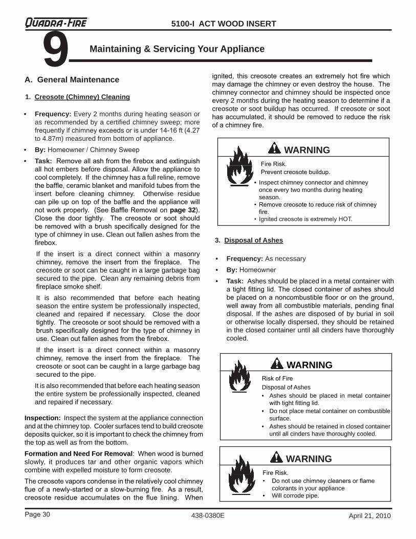
Fire Risk.Prevent creosote buildup.
WARNING
• Inspectchimneyconnectorandchimneyonceeverytwomonthsduringheatingseason.
• Remove creosote to reduce risk of chimney fire.
• Ignited creosote is extremely HOT.
ignited, this creosote creates an extremely hot fire which may damage the chimney or even destroy the house. The chimneyconnectorandchimneyshouldbeinspectedonceevery2monthsduringtheheatingseasontodetermineifacreosoteorsootbuilduphasoccurred.Ifcreosoteorsoothas accumulated, it should be removed to reduce the risk of a chimney fire.

Page �1
5100-I ACT WOOD INSERTR
438-0380EApril21,2010
4. Glass Cleaning
• Frequency: Asnecessary• By: Homeowner• Task: Clean glass with a nonabrasive glass cleaner.
Abrasive cleaners may scratch and cause glass tocrack. If thedepositsontheglassarenotveryheavy,normal glass cleaners work well. Heavier deposits may beremovedbyusingadampclothdippedinwoodashesorbyusingacommerciallyavailableovencleaner.Afterusing an oven cleaner, it is advisable to remove anyresiduewithaglasscleanerorsoapandwater. Ovencleaner left on during the next firing can permanently stain the glass and damage the finish on plated metal surfaces.
5. Cleaning Plated Surfaces
• Frequency: Asnecessary• By: Homeowner• Task: Clean all the fingerprints and oils from plated
surfacesBEFORE firing the appliance for the first time. If not cleaned properly before lighting your first fire, the oils can cause permanent markings on the plating. Use warmsoapywaterandasoft rag,glasscleanerandapapertowel,orvinegarandapapertoweltoremovetheoils.Aftertheplatingiscured,theoilswillnotaffectthefinish and little maintenance is required. Wipe clean as needed.
Quadra-Fire stoves are equipped with ceramic super heat-resistant glass, which can only be broken by impact or misuse.Donotslamstovedoororimpacttheglass.Whenclosing door, make sure that logs do not protrude against the glass. Inspect glass regularly. If you find a crack or break, immediately put the fire out and return the door to your dealer forreplacementofglassbeforefurtheruse.A portion of the combustion air entering the firebox is deflected down over the inside of the door glass. This air flow “washes” the glass, helping to keep smoke from adhering to its surface. When operated at a low burn rate, less air will be flowing over the glass and the smoky, relatively cool condition of a low fire willcausetheglasstobecomecoated.Operatingtheappli-ance with the Primary Air Control all the way open for 15-�0 minutesshouldremovethebuiltupcoating.
Handle glass assembly with care.
When cleaning glass:• Avoid striking, scratching or
slammingglass.• Do NOT clean glass when hot.
CAUTION
• Do NOT use abrasive cleaners.• Use a hard water deposit glass cleaner on white film.• Use commercial oven cleaner on heavier deposits.• Removeallresidueofovencleanerorwillpermanently
stain glass on next firing.• Refertomaintenanceinstructions.
GlassAssembly
CAUTION• Donotusepolisheswithabrasives,itwillscratchplatedsurface.
5100-I ACT WOOD INSERT
Page �� April21,2010
R
438-0380E
B. Quick Reference Maintenance Guide
2 2
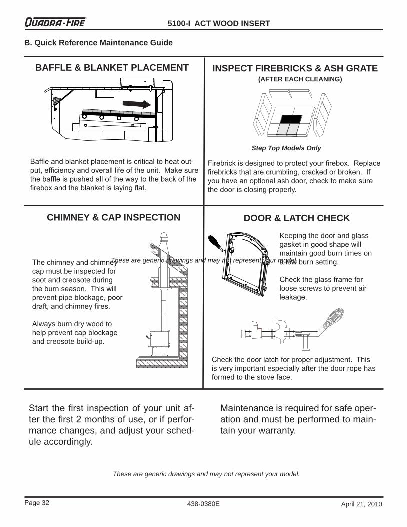
Baffle and blanket placement is critical to heat out-put, efficiency and overall life of the unit. Make sure the baffle is pushed all of the way to the back of the firebox and the blanket is laying flat.
Firebrick is designed to protect your firebox. Replace firebricks that are crumbling, cracked or broken. If you have an optional ash door, check to make sure thedoorisclosingproperly.
The chimney and chimney capmustbeinspectedforsootandcreosoteduringthe burn season. This will prevent pipe blockage, poor draft, and chimney fires.
Alwaysburndrywoodtohelp prevent cap blockage andcreosotebuild-up.
Keepingthedoorandglassgasket in good shape will maintaingoodburntimesonalowburnsetting.
Check the glass frame for loosescrewstopreventairleakage.
Check the door latch for proper adjustment. This isveryimportantespeciallyafterthedoorropehasformedtothestoveface.
Start the first inspection of your unit af-ter the first � months of use, or if perfor-mancechanges,andadjustyoursched-uleaccordingly.
BAFFLE & BLANKET PLACEMENT INSPECT FIREBRICKS & ASH GRATE(AFTER EACH CLEANING)
CHIMNEY & CAP INSPECTION DOOR & LATCH CHECK
Step Top Models Only
Maintenance is required for safe oper-ationandmustbeperformedtomain-tainyourwarranty.
Thesearegenericdrawingsandmaynotrepresentyourmodel.
Thesearegenericdrawingsandmaynotrepresentyourmodel.
Page ��
5100-I ACT WOOD INSERTR
438-0380EApril21,2010
Quadra-Fire stoves are equipped with ceramic super heat-resistant glass, which can only be broken by impact or misuse.Donotslamstovedoororimpacttheglass.Whenclosing door, make sure that logs do not protrude against the glass. Inspect glass regularly. If you find a crack or break, immediately put the fire out and return the door to your dealer forreplacementofglassbeforefurtheruse.
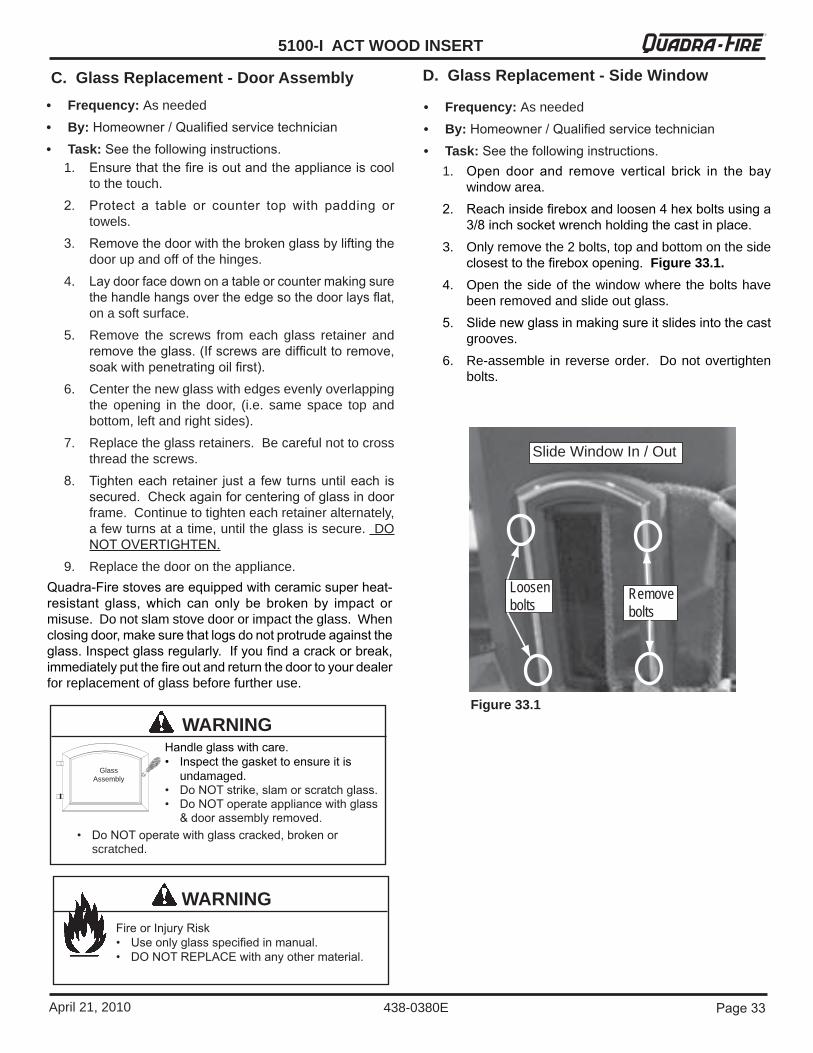
C. Glass Replacement - Door Assembly• Frequency: Asneeded• By: Homeowner / Qualified service technician• Task: See the following instructions.
1. Ensure that the fire is out and the appliance is cool tothetouch.
�. Protect a table or counter top with padding or towels.
�. Remove the door with the broken glass by lifting the doorupandoffofthehinges.
4. Lay door face down on a table or counter making sure the handle hangs over the edge so the door lays flat, onasoftsurface.
5. Remove the screws from each glass retainer andremove the glass. (If screws are difficult to remove, soak with penetrating oil first).
6. Centerthenewglasswithedgesevenlyoverlappingthe opening in the door, (i.e. same space top andbottom,leftandrightsides).
7. Replacetheglassretainers.Becarefulnottocrossthreadthescrews.
8. Tighten each retainer just a few turns until each is secured. Check again for centering of glass in door frame.Continuetotighteneachretaineralternately,afewturnsatatime,untiltheglassissecure.DONOT OVERTIGHTEN.
9. Replacethedoorontheappliance.
Handle glass with care.• Inspect the gasket to ensure it is
undamaged.• Do NOT strike, slam or scratch glass.• Do NOT operate appliance with glass
& door assembly removed.
WARNING
GlassAssembly
• Do NOT operate with glass cracked, broken or scratched.
Fire or Injury Risk• Use only glass specified in manual.• DO NOT REPLACE with any other material.
WARNING
D. Glass Replacement - Side Window
• Frequency: Asneeded• By: Homeowner / Qualified service technician• Task: See the following instructions.
1. Open door and remove vertical brick in the bay windowarea.
�. Reach inside firebox and loosen � hex bolts using a �/8 inch socket wrench holding the cast in place.
3. Onlyremovethe2bolts,topandbottomonthesideclosest to the firebox opening. Figure 33.1.
4. Openthesideofthewindowwheretheboltshavebeenremovedandslideoutglass.
5. Slide new glass in making sure it slides into the cast grooves.
6. Re-assemble in reverseorder. Donotovertightenbolts.
Loosen bolts
Remove bolts
Slide Window In / Out
Figure 33.1
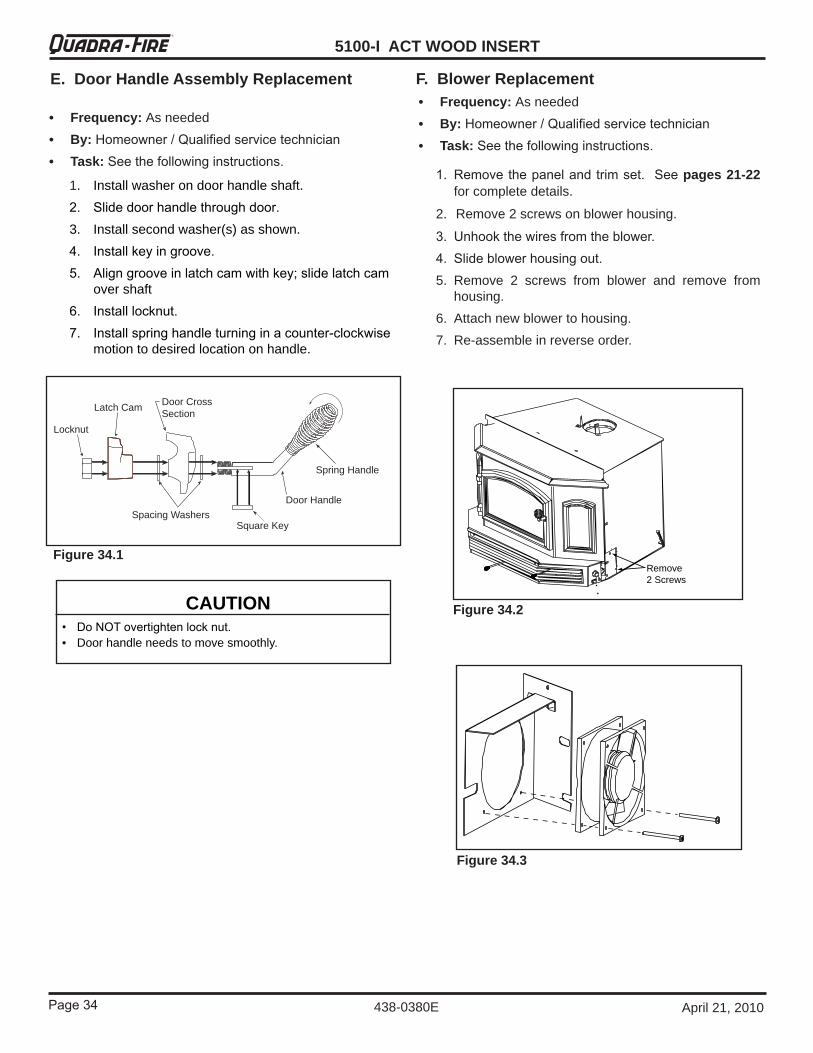
5100-I ACT WOOD INSERT
Page �� April21,2010
R
438-0380E
E. Door Handle Assembly Replacement
1. Installwasherondoorhandleshaft.�. Slide door handle through door.3. Installsecondwasher(s)asshown.�. Install key in groove.5. Align groove in latch cam with key; slide latch cam
overshaft6. Install locknut.7. Install spring handle turning in a counter-clockwise
motiontodesiredlocationonhandle.
CAUTION• Do NOT overtighten lock nut.• Doorhandleneedstomovesmoothly.
Locknut
Door Cross Section Latch Cam
Spacing WashersSquare Key
Door Handle
Spring Handle
• Frequency: Asneeded• By: Homeowner / Qualified service technician• Task: See the following instructions.
Figure 34.1
1. Remove the panel and trim set. See pages 21-22 forcompletedetails.
2. Remove2screwsonblowerhousing.
�. Unhook the wires from the blower.�. Slide blower housing out.5. Remove 2 screws from blower and remove from
housing.6. Attachnewblowertohousing.7. Re-assembleinreverseorder.
F. Blower Replacement• Frequency: Asneeded• By: Homeowner / Qualified service technician• Task: See the following instructions.
Remove 2 Screws
Figure 34.2
Figure 34.3

Page �5
5100-I ACT WOOD INSERTR
438-0380EApril21,2010
The firebox is lined with high quality firebrick, which has exceptional insulating properties. There is no need to use a grate; simply build a fire on the firebox floor. Do not operate appliance without firebrick.
G. Firebrick Replacement
• Frequency: Asneeded• By: Homeowner / Qualified service technician• Task: See the following instructions.
1. Becertaincoalsarecompletelycold. Removealloldbrick and ash from unit and vacuum out firebox.
�. Remove new brick set from box and lay out to diagram asshown.
�. Lay bottom bricks in unit.�. Install rear bricks on the top of the bottom bricks. Slide
top of bricks under clip on back of firebox wall and push bottom of brick back.
5. Install side bricks. Slide top of brick under clips on side of firebox and push the bottom of the brick until it is flush withthesideoftheunit.
NOTE: Do not operate unit with any firebrick missing. It will void the warranty.
Figure 35.1
1
1
1
1
1
1
1
1 11
1
11
1
2 2
33
4
4
56
6
77
8
8
9 910
10
11
12
12
4-1/2”
7-1/2”6-3/4” 9
3-3/4”
3-3/8”
8-1/2”
4-1/2”
5/8”3/4”
7
2-7/8”
4-7/8”
881o
Figure 35.2
Use Part 8��-0550 when ordering individual brick. Provide brick dimension or copy this page, mark the desired brick and take it to your authorized dealer.
*Use Part SRV��6-0�80 when ordering the � bricks withholes.
Nbr Brick Size Qty1 9 x �-1/� x 1-1/�” 14
2* 9 x �-1/� x 1/1/�” with hole 2
3 9 x � x 1-1/�” 24 8-1/� x 1-�/� x 1-1/�” 25 � x 1-�/� x 1-1/�” 16 9 x � x 1-1/�” 27 see drawing, Figure �1.� 28 see drawing, Figure �1.� 29 see drawing, Figure �1.� 2
10 7-1/� x �-1/� x 1-1/�” 211 9 x �-1/� x 1-1/�” 112 8-�/�” X �-1/�” X 1-1/�” 2

5100-I ACT WOOD INSERT
Page �6 April21,2010
R
438-0380E
H. Baffle Removal• Frequency: Asneeded• By: Homeowner / Qualified service technician• Task: See the following instructions.
1. Remove all ash from firebox, and extinguish all hot embersbeforedisposalintoametalcontainer.
�. Remove ceramic blanket from above the baffle.�. With a �/16 inch Allen wrench, remove � front manifold
tuberetainerboltsontheairchannelundertheendofthe front tubes. NOTE: Soak the bolts with penetrating oilforatleast15minutesbeforetryingtoremovethem.Figure 36.1.
�. To remove manifold tubes, slide the tube to one side until one end is out of its hole. Then, while lifting that end of the fiber board baffle, pull tube up over the air channelandoutofholeattheotherend.Itisnecessaryto remove the first two tubes in order to remove the baffle. NOTE: When replacing the manifold tubes, besurethetubewiththelargerholesisplacedinthefrontforyourinserttooperateproperly.
5. Slide fiber board baffle forward to front of stove and straightoutthroughdoor. Figure 36.2.
6. To install the fiber board baffle, repeat steps � through � in reverse. Be sure the fiber board baffle and ceramic blanket are pushed back fully into position.
Ceramic Blanket
Baffle
Allen wrench on retainer bolt
First tube has larger holes
Figure 36.1
Figure 36.2
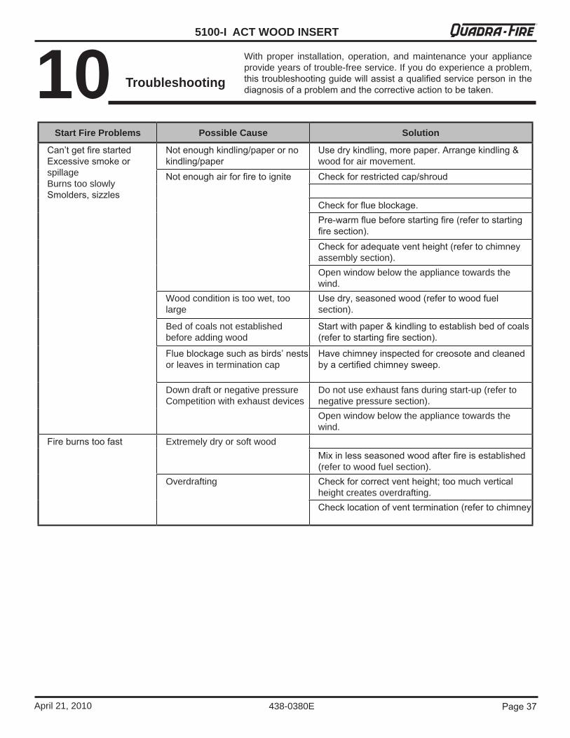
Page �7
5100-I ACT WOOD INSERTR
438-0380EApril21,2010
10 Troubleshooting
Withproper installation, operation, andmaintenance your applianceprovideyearsoftrouble-freeservice.Ifyoudoexperienceaproblem,this troubleshooting guide will assist a qualified service person in the diagnosis of a problem and the corrective action to be taken.
Start Fire Problems Possible Cause Solution
Can’t get fire startedExcessive smoke or spillageBurnstooslowlySmolders, sizzles
Not enough kindling/paper or no kindling/paper
Use dry kindling, more paper. Arrange kindling & woodforairmovement.
Not enough air for fire to ignite Check for restricted cap/shroud
Check for flue blockage.Pre-warm flue before starting fire (refer to starting fire section).Check for adequate vent height (refer to chimney assemblysection).Openwindowbelowtheappliancetowardsthewind.
Woodconditionistoowet,toolarge
Use dry, seasoned wood (refer to wood fuel section).
Bedofcoalsnotestablishedbeforeaddingwood
Start with paper & kindling to establish bed of coals (refer to starting fire section).
Flue blockage such as birds’ nests orleavesinterminationcap
Have chimney inspected for creosote and cleaned by a certified chimney sweep.
DowndraftornegativepressureCompetitionwithexhaustdevices
Donotuseexhaustfansduringstart-up(refertonegativepressuresection).Openwindowbelowtheappliancetowardsthewind.
Fire burns too fast ExtremelydryorsoftwoodMix in less seasoned wood after fire is established (refertowoodfuelsection).
Overdrafting Check for correct vent height; too much vertical heightcreatesoverdrafting.Check location of vent termination (refer to chimney
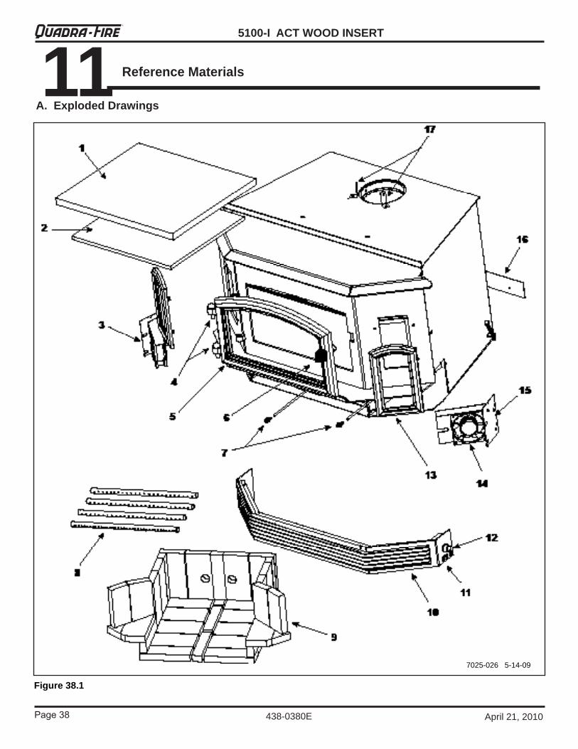
5100-I ACT WOOD INSERT
Page �8 April21,2010
R
438-0380E
11 Reference Materials
A. Exploded Drawings
Figure 38.1
7025-0265-14-09

Page �9
5100-I ACT WOOD INSERTR
438-0380EApril21,2010
B. Service Parts & Accessories
When requesting service or replacement parts for yourappliance please provide model number and serialnumber.allpartslistedmaybeorderdfromanauthorizeddealer.
IMPORTANT: THIS IS DATED INFORMATIONToordertheentireassembly,orderthetoplinepartnumberonly.Toorderanindividualpartfromanassembly,orderthepart(s)listedintheindentedportion.
HOW TO ORDER
Stocked at DepotItem Description Comments Part Number
1 Ceramic Fiber Blanket, 1/� “ Thick 832-3390 Y2 Baffle Fiberboard SRV��8-0��0 Y3 Mount,Blower,Left SRV��0-118�
4 Hinge Pins, 1/�”Gold 832-0250Nickel 430-5320
5 DoorAssemblyBlack DR-27BKGold DR-27GDNickel DR-�7NL
6 Spring Handle, 1/�”Gold 832-0620 YNickel 250-8330
7 Spring Handle, 1/�”Gold 832-0630 YNickel 250-8340
CamLatch 430-1141DoorGlassAssembly 7000-011 YDoor Handle Only 430-1131Gasket, Glass Tape, �/� “ �/�” x 5 Ft, Dealer Cut to Size 832-0460 YGlass Frame Set Qty: � Pc 832-1540Key,CamLatch 430-1151Nut, keps Lock, 8-�� Qty: �0 ��6-0060/�0 YNut, Locking Door Handle Qty: �� ��6-0100/�� YRope, Door, �/�” X 8�” �/�” x 7 Ft, Dealer Cut to Size 832-1680 Y
Trim Ring, DoorGold Trim 430-2702Nickel Trim 430-5350
Washer, Sae, �/8 (� Ea) Qty: � 832-09908 Manifold Tube Set TUBES-��8 Y
Bushing .06� Od X .�75Id 438-0370Manifold Clip/Screws (�) 832-0661 Y
9 Brick Assembly BRICK-438Brick, Single Qty: 1 832-0550 YBrick, Uncut, Set Of 6 Qty: 6 832-3040 YFirebrick W/Hole Qty: � SRV��6-0�80 Y
10 Grill Assembly, Complete SetGold 832-3100Nickel 8��-�100NL
11 Switch, Rocker 230-0730 Y12 knob, Speed Control KnobOnly 200-2041 Y
BlowerCordOnly 832-2410 YGrill Panel Assembly Frame Only SRV��8-5610
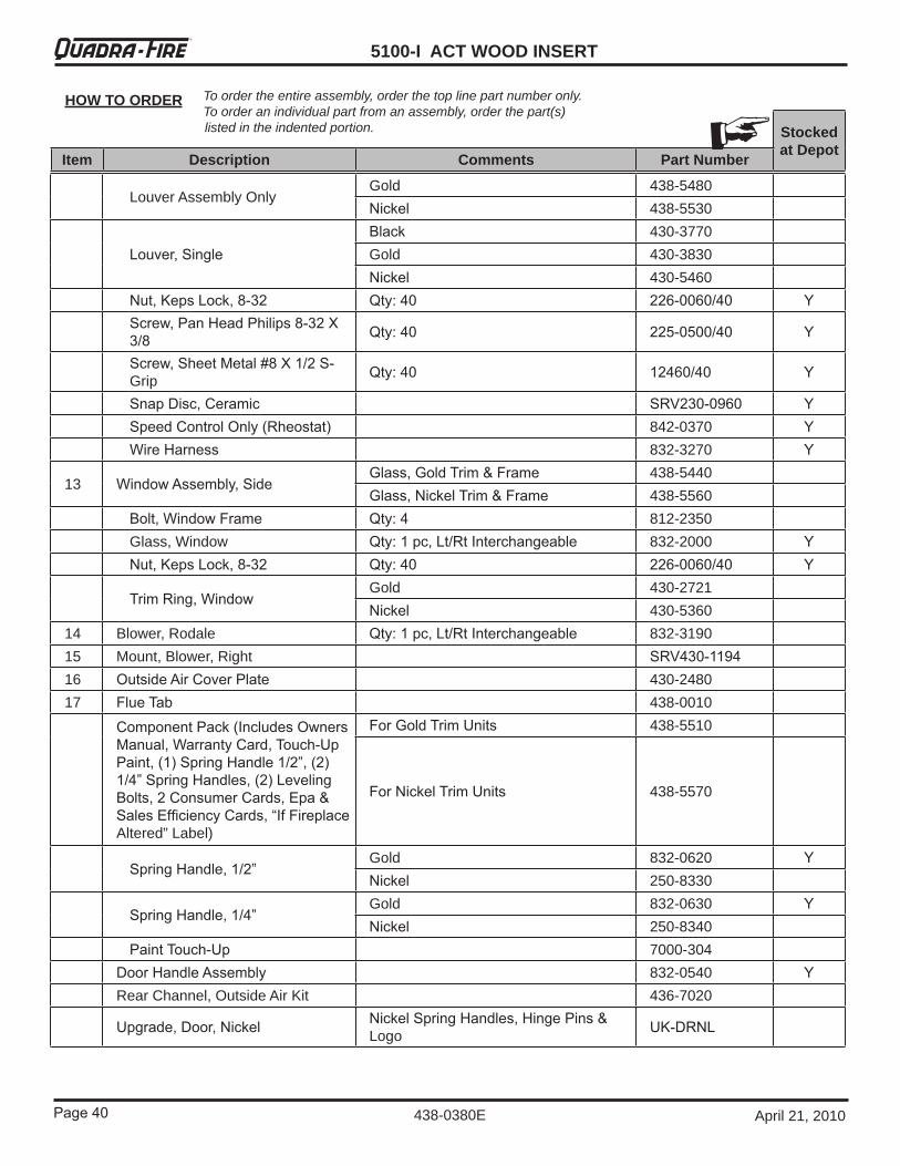
5100-I ACT WOOD INSERT
Page �0 April21,2010
R
438-0380E
Toordertheentireassembly,orderthetoplinepartnumberonly.Toorderanindividualpartfromanassembly,orderthepart(s)listedintheindentedportion.
HOW TO ORDER
Stocked at DepotItem Description Comments Part Number
LouverAssemblyOnlyGold 438-5480Nickel 438-5530
Louver, SingleBlack 430-3770Gold 430-3830Nickel 430-5460
Nut, keps Lock, 8-�� Qty: �0 ��6-0060/�0 YScrew, Pan Head Philips 8-�� X �/8 Qty: �0 ��5-0500/�0 Y
Screw, Sheet Metal #8 X 1/� S-Grip Qty: �0 1��60/�0 Y
Snap Disc, Ceramic SRV��0-0960 YSpeed Control Only (Rheostat) 842-0370 YWire Harness 832-3270 Y
13 Window Assembly, SideGlass, Gold Trim & Frame 438-5440Glass, Nickel Trim & Frame 438-5560
Bolt, Window Frame Qty: � 812-2350Glass,Window Qty: 1 pc, Lt/Rt Interchangeable 832-2000 YNut, keps Lock, 8-�� Qty: �0 ��6-0060/�0 Y
Trim Ring, WindowGold 430-2721Nickel 430-5360
14 Blower,Rodale Qty: 1 pc, Lt/Rt Interchangeable 832-319015 Mount,Blower,Right SRV��0-119�16 Outside Air Cover Plate 430-248017 Flue Tab 438-0010
Component Pack (Includes Owners Manual, Warranty Card, Touch-Up Paint, (1) Spring Handle 1/�”, (�) 1/�” Spring Handles, (�) Leveling Bolts, � Consumer Cards, Epa & Sales Efficiency Cards, “If Fireplace Altered”Label)
For Gold Trim Units 438-5510
For Nickel Trim Units 438-5570
Spring Handle, 1/�”Gold 832-0620 YNickel 250-8330
Spring Handle, 1/�”Gold 832-0630 YNickel 250-8340
Paint Touch-Up 7000-304Door Handle Assembly 832-0540 YRearChannel,OutsideAirKit 436-7020
Upgrade, Door, Nickel Nickel Spring Handles, Hinge Pins & Logo Uk-DRNL
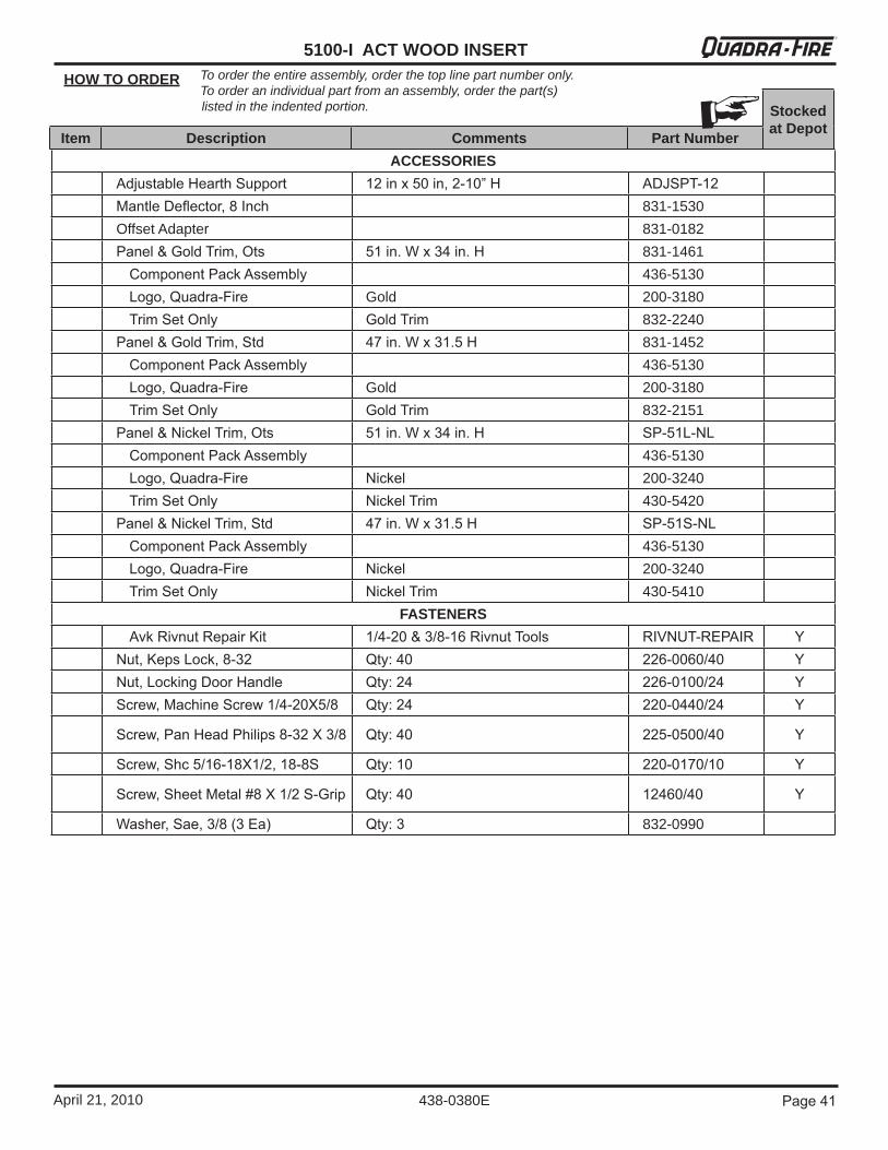
Page �1
5100-I ACT WOOD INSERTR
438-0380EApril21,2010
Toordertheentireassembly,orderthetoplinepartnumberonly.Toorderanindividualpartfromanassembly,orderthepart(s)listedintheindentedportion.
HOW TO ORDER
Stocked at DepotItem Description Comments Part Number
ACCESSORIESAdjustable Hearth Support 1� in x 50 in, �-10” H ADJSPT-1�Mantle Deflector, 8 Inch 831-1530OffsetAdapter 831-0182Panel & Gold Trim, Ots 51 in. W x �� in. H 831-1461
Component Pack Assembly 436-5130Logo, Quadra-Fire Gold 200-3180Trim Set Only Gold Trim 832-2240
Panel & Gold Trim, Std �7 in. W x �1.5 H 831-1452Component Pack Assembly 436-5130Logo, Quadra-Fire Gold 200-3180Trim Set Only Gold Trim 832-2151
Panel & Nickel Trim, Ots 51 in. W x �� in. H SP-51L-NLComponent Pack Assembly 436-5130Logo, Quadra-Fire Nickel 200-3240Trim Set Only Nickel Trim 430-5420
Panel & Nickel Trim, Std �7 in. W x �1.5 H SP-51S-NLComponent Pack Assembly 436-5130Logo, Quadra-Fire Nickel 200-3240Trim Set Only Nickel Trim 430-5410
FASTENERSAvk Rivnut Repair kit 1/�-�0 & �/8-16 Rivnut Tools RIVNUT-REPAIR Y
Nut, keps Lock, 8-�� Qty: �0 ��6-0060/�0 YNut, Locking Door Handle Qty: �� ��6-0100/�� YScrew, Machine Screw 1/�-�0X5/8 Qty: �� ��0-0��0/�� Y
Screw, Pan Head Philips 8-�� X �/8 Qty: �0 ��5-0500/�0 Y
Screw, Shc 5/16-18X1/�, 18-8S Qty: 10 ��0-0170/10 Y
Screw, Sheet Metal #8 X 1/� S-Grip Qty: �0 1��60/�0 Y
Washer, Sae, �/8 (� Ea) Qty: � 832-0990
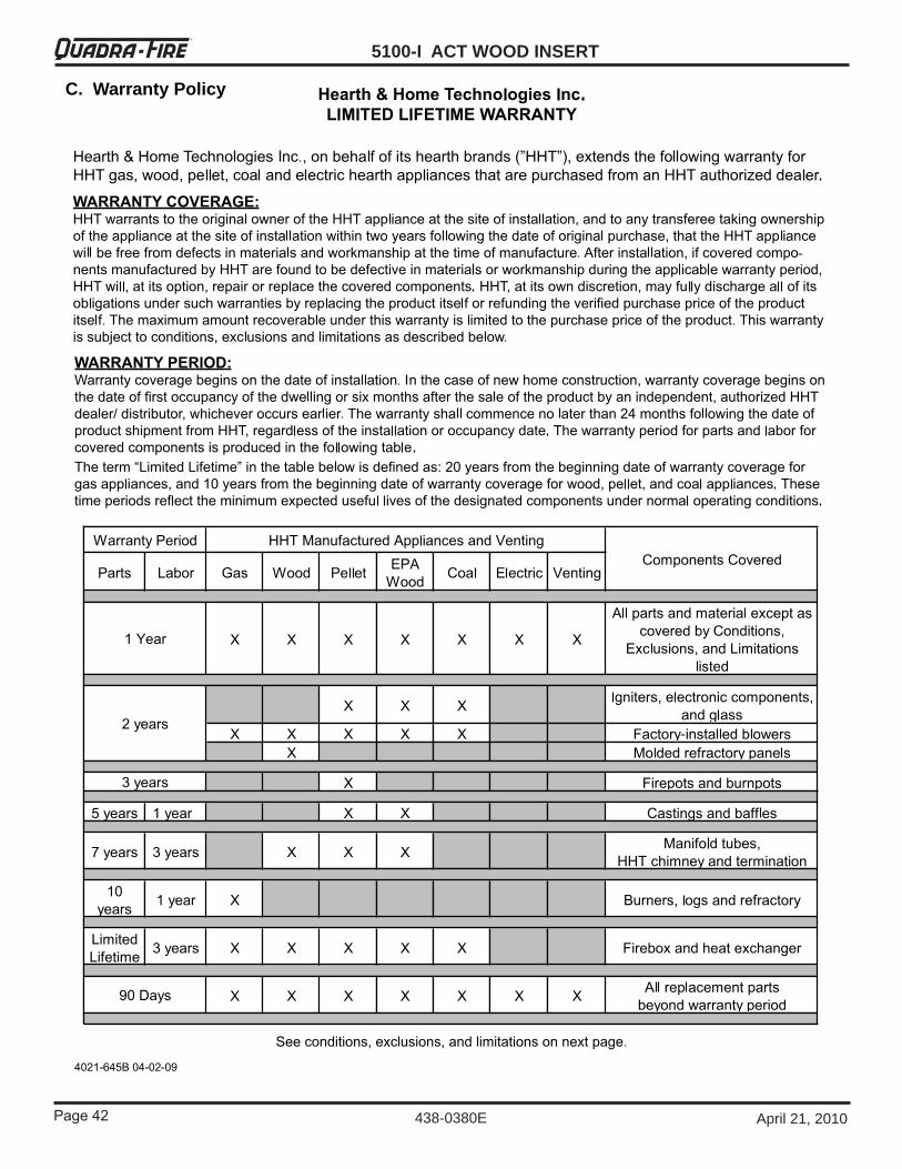
5100-I ACT WOOD INSERT
Page �� April21,2010
R
438-0380E
C. Warranty Policy
Page ��
5100-I ACT WOOD INSERTR
438-0380EApril21,2010
Page �� April21,2010438-0380E
R
Hearth & Home Technologies1445 North HighwayColville, WA 99114
Division of HNI INDUSTRIES
CONTACT INFORMATION:
Please contact your Quadra-Fire dealer with any questions or concerns. For the number of your nearest Quadra-Fire dealer,
please visit our web site at www.quadrafire.com
DO NOT DISCARD THIS MANUAL
NOTICE
• Important operatingand maintenance in-structionsincluded.
• Leavethismanualwithparty responsible foruseandoperation.
• Read, understand andfollowtheseinstructionsforsafeinstallationandoperation.
DO NOTDISCARD
Date purchased/installed:
Serial Number: Location on appliance:
Dealership purchased from: Dealer phone:
Notes:
Date purchased/installed:
Serial Number: Location on appliance:
Dealership purchased from: Dealer phone:
Notes:
We recommend that you record the following pertinent information for your 5100-I Wood Insert (ACT)
This product may be covered by one or more of the following patents: (United States) 5341794, 5263471, 6688302, 7216645,7047962or other U.S. and foreign patents pending.


![ACT Government - AUSTRALIAN CAPITAL TERRITORY CONTRACT NUMBER: [INSERT] CONTRACT … · 2019. 11. 6. · australian capital territory contract number: [insert] contract name: [insert]](https://img.dokumen.tips/doc/110x75/60aebbf72ac8c7702f4b433a/act-government-australian-capital-territory-contract-number-insert-contract.jpg)


