Embed Size (px)
Citation preview

Page 1 of 34
5.1 Electricity - Basics of Electricity 2 – Questions
Q1. (a) A 3.0 kW electric kettle heats 2.4 kg of water from 16°C to 100°C in 320 seconds.
(i) Calculate the electrical energy supplied to the kettle.
______________________________________________________________
______________________________________________________________
(ii) Calculate the heat energy supplied to the water. specific heat capacity of water = 4200 J kg–1 K–1
______________________________________________________________
______________________________________________________________
______________________________________________________________
(iii) Give one reason why not all the electrical energy supplied to the kettle is transferred to the water.
______________________________________________________________
______________________________________________________________ (4)
(b) The potential difference supplied to the kettle in part (a) is 230 V.
(i) Calculate the resistance of the heating element of the kettle.
______________________________________________________________
______________________________________________________________
______________________________________________________________
(ii) The heating element consists of an insulated conductor of length 0.25 m and diameter 0.65 mm. Calculate the resistivity of the conductor.
______________________________________________________________
______________________________________________________________
______________________________________________________________
______________________________________________________________
______________________________________________________________ (5)
(Total 9 marks)
Page 2 of 34
Q2. (a) Define resistance.
___________________________________________________________________
___________________________________________________________________
___________________________________________________________________ (1)
(b) (i) Sketch onto the axes below a graph of the variation of current with potential difference for a filament lamp.
(1)
(ii) State and explain, in terms of electron flow, how the resistance of the filament lamp changes as the current in the lamp increases.
______________________________________________________________
______________________________________________________________
______________________________________________________________
______________________________________________________________
______________________________________________________________
______________________________________________________________ (3)
(Total 5 marks)
Q3. (a) A steady current of 0.25 A passes through a torch bulb for 6 minutes.
Calculate the charge which flows through the bulb in this time.
___________________________________________________________________
___________________________________________________________________
___________________________________________________________________

Page 3 of 34
(2)
(b) The torch bulb is now connected to a battery of negligible internal resistance. The battery supplies a steady current of 0.25 A for 20 hours. In this time the energy transferred in the bulb is 9.0 × 10⁴ J. Calculate
(i) the potential difference across the bulb,
______________________________________________________________
______________________________________________________________
______________________________________________________________
(ii) the power of the bulb.
______________________________________________________________
______________________________________________________________
______________________________________________________________ (3)
(Total 5 marks)
Q4. (a) A solar panel of area 2.5 m2 is fitted to a satellite in orbit above the Earth. The panel
produces a current of 2.4 A at a potential difference of 20 V when solar radiation is incident normally on it.
(i) Calculate the electrical power output of the panel.
______________________________________________________________
______________________________________________________________
______________________________________________________________
(ii) Solar radiation on the satellite has an intensity of 1.4 kW m–2. Calculate the efficiency of the panel.
______________________________________________________________
______________________________________________________________
______________________________________________________________
______________________________________________________________
______________________________________________________________ (4)
(b) The back-up power system in the satellite is provided by a radioactive isotope enclosed in a sealed container which absorbs the radiation from the isotope. Energy from the radiation is converted to electrical energy by means of a thermoelectric module.
Page 4 of 34
(i) The isotope has an activity of 1.1 × 10¹⁴ Bq and produces α particles of energy 5.1 MeV. Show that the container absorbs energy from the α particles at a rate of 90 J s–1.
______________________________________________________________
______________________________________________________________
______________________________________________________________
______________________________________________________________
______________________________________________________________
______________________________________________________________
______________________________________________________________
(ii) The isotope has a half-life of 90 years. Calculate the decay constant λ of this isotope.
______________________________________________________________
______________________________________________________________
______________________________________________________________
(iii) The mass number of the isotope is 239. Calculate the mass of isotope needed for an activity of 1.1 × 10¹⁴ Bq.
______________________________________________________________
______________________________________________________________
______________________________________________________________
______________________________________________________________
______________________________________________________________ (7)
(Total 11 marks)
Q5.

Page 5 of 34
(a) An X-ray tube operates with a pd across the tube of 80 kV. The figure above shows the X-ray spectrum emitted. Explain why the spectrum has spikes at specific photon energies.
___________________________________________________________________
___________________________________________________________________
___________________________________________________________________
___________________________________________________________________ (2)
(b) The pd across the tube is increased to 90 kV. Sketch on the figure above the X-ray spectrum produced at this new pd.
(3)
(c) At the working pd of 80 kV, the anode current was 120 mA. The X-ray tube has an efficiency of 0.70 %. Calculate the rate of production of heat at the anode.
___________________________________________________________________
___________________________________________________________________
___________________________________________________________________
___________________________________________________________________ (3)
(Total 8 marks)
Q6. (a) A 2.0 kW heater is used to heat a room from 5 °C to 20 °C. The mass of air in the
room is 30 kg. Under these conditions the specific heat capacity of air = 1000 J kg–1 K–1.
Page 6 of 34
Calculate
(i) the gain in thermal energy of the air,
______________________________________________________________
______________________________________________________________
(ii) the minimum time required to heat the room.
______________________________________________________________
______________________________________________________________
______________________________________________________________ (4)
(b) State and explain one reason why the actual time taken to heat the room is longer than the value calculated in part (a)(ii).
___________________________________________________________________
___________________________________________________________________
___________________________________________________________________
___________________________________________________________________ (2)
(Total 6 marks)
Q7. A cordless phone handset contains two rechargeable cells connected in series. Each cell has an emf of 2.0 V and, when fully charged, the combination stores energy sufficient to provide 850 mA for 1 hour.
(a) Calculate the total energy stored by the two cells when fully charged.
energy stored ____________________ J (3)
(b) The internal resistance of each cell is 0.60 . Calculate the potential difference across the two cells when they are connected in series across a 20.0 load.
Page 7 of 34
potential difference ____________________ V (3)
(Total 6 marks)
Q8. The heater in a kettle, designed to operate from the 12 V battery in a car, has a power rating of 130 W.
(a) Calculate the current drawn from the battery by the kettle.
current ____________________ A (2)
(b) The energy needed to raise the temperature of two cups of cold water to boiling point is 170 kJ. Calculate the minimum time, in minutes, that it would take to raise the temperature of this water to its boiling point.
time ____________________ minutes (3)
(c) The internal resistance of the battery affects the efficiency of the transfer of energy from the battery to the kettle. Explain what causes internal resistance and why this affects the efficiency.
___________________________________________________________________
___________________________________________________________________
___________________________________________________________________
___________________________________________________________________
___________________________________________________________________ (3)
(Total 8 marks)

Page 8 of 34
Q9. The figure below shows a prototype electric liquidiser used, for example, in making soup. It consists of a motor which is designed to run from a 110 V d.c. supply and uses energy at a rate of 40 W when making ‘thin’ soups. The rate of using energy increases when thicker soup is being liquidised.
(a) Calculate the effective resistance when the mixer is operating at 40 W from a 110 V supply.
(2)
(b) The mixer is to have the option of running from a 230 V supply. In this case, a resistor is included in series with the motor which itself can be treated as a pure resistor.
(i) Calculate the magnitude of the series resistor needed.
(ii) Determine the percentage of the input power that is dissipated in the series resistor.
(5)
(c) The designer warns users against using the liquidiser to try to mix stiff materials such as pastry. State and explain what is likely to happen if this warning is ignored.
___________________________________________________________________
___________________________________________________________________
___________________________________________________________________
___________________________________________________________________ (3)
(d) A cordless version of the mixer operates at 40 W from a 14 V battery that has a capacity of 1.3 A-h. For how long could a fully-charged battery operate the mixer? Give your answer in h.
(2)

Page 9 of 34
(Total 12 marks)
Q10. (a) A semiconducting diode is an example of a non-ohmic component. State what is
meant by a non-ohmic component.
___________________________________________________________________
___________________________________________________________________ (1)
(b) A filament lamp is also an example of a non-ohmic component.
(i) Sketch on the axes below the current-voltage characteristic for a filament lamp.
(2)
(ii) State, with reference to the current-voltage characteristic you have drawn, how the resistance of the lamp changes as the pd across its terminals changes.
______________________________________________________________
______________________________________________________________ (1)
(c) A filament lamp has a power rating of 36 W when there is a pd across its terminals of 12V.
(i) Calculate the resistance of the filament when the pd across its terminals is 12V.
answer = ______________________ Ω (2)
Page 10 of 34
(ii) A student predicts that if the pd across the bulb is reduced to 6.0 V the power rating of the bulb would be 9.0 W. State and explain how in practice the power rating will be slightly different from this value.
______________________________________________________________
______________________________________________________________
______________________________________________________________
______________________________________________________________
______________________________________________________________
______________________________________________________________ (3)
(Total 9 marks)
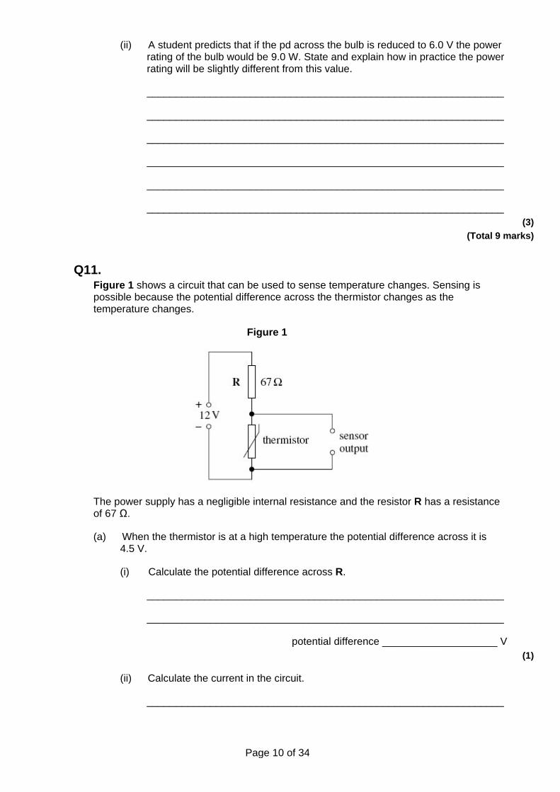
Q11. Figure 1 shows a circuit that can be used to sense temperature changes. Sensing is possible because the potential difference across the thermistor changes as the temperature changes.
Figure 1
The power supply has a negligible internal resistance and the resistor R has a resistance of 67 Ω.
(a) When the thermistor is at a high temperature the potential difference across it is 4.5 V.
(i) Calculate the potential difference across R.
______________________________________________________________
______________________________________________________________
potential difference ____________________ V (1)
(ii) Calculate the current in the circuit.
______________________________________________________________

Page 11 of 34
______________________________________________________________
______________________________________________________________
current ____________________ A (2)
(b) (i) The temperature of the thermistor changes to 25 °C and its resistance becomes 360 Ω. Show that the potential difference across the thermistor at 25 °C is about 10 V.
______________________________________________________________
______________________________________________________________
______________________________________________________________
______________________________________________________________ (3)
(ii) Calculate the power dissipated in the resistor R when the thermistor temperature is 25 °C, giving an appropriate unit for your answer.
______________________________________________________________
______________________________________________________________
______________________________________________________________
______________________________________________________________
______________________________________________________________
______________________________________________________________
power dissipated _____________________________________________ (4)
(c) The circuit is modified as shown in Figure 2. A resistor of resistance 570 Ω is connected in parallel with the thermistor.
Figure 2
For the circuit in Figure 2 calculate the current in the 67 Ω resistor when the thermistor temperature is 25 °C.

Page 12 of 34
___________________________________________________________________
___________________________________________________________________
___________________________________________________________________
___________________________________________________________________
___________________________________________________________________
current in 67 Ω resistor ____________________ A (4)
(d) Explain, in terms of charge carriers, why the resistance of the thermistor decreases as the temperature rises.
___________________________________________________________________
___________________________________________________________________
___________________________________________________________________
___________________________________________________________________
___________________________________________________________________
___________________________________________________________________
___________________________________________________________________ (3)
(Total 17 marks)
Q12. In parts (i) and (ii) circle the letter that corresponds to the correct answer.
(i) The resistance of a negative temperature coefficient (ntc) thermistor
A increases as temperature increases.
B is constant at temperatures below 0 °C.
C increases as temperature decreases.
D falls to zero when a critical temperature is reached. (1)
(ii) The unit of potential difference can be expressed as
A C s–1
B J C–1
C V A–1
D J A–1
(1)
Page 13 of 34
(Total 2 marks)
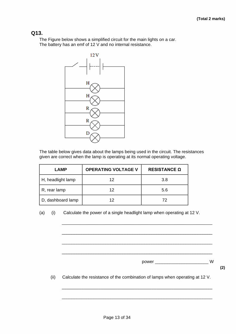
Q13. The Figure below shows a simplified circuit for the main lights on a car. The battery has an emf of 12 V and no internal resistance.
The table below gives data about the lamps being used in the circuit. The resistances given are correct when the lamp is operating at its normal operating voltage.
LAMP OPERATING VOLTAGE V RESISTANCE Ω
H, headlight lamp 12 3.8
R, rear lamp 12 5.6
D, dashboard lamp 12 72
(a) (i) Calculate the power of a single headlight lamp when operating at 12 V.
______________________________________________________________
______________________________________________________________
______________________________________________________________
______________________________________________________________
power ______________________ W (2)
(ii) Calculate the resistance of the combination of lamps when operating at 12 V.
______________________________________________________________
______________________________________________________________

Page 14 of 34
______________________________________________________________
______________________________________________________________
______________________________________________________________
resistance ______________________ Ω (3)
(iii) Calculate the total power of the combination of lamps when operating at 12 V.
______________________________________________________________
______________________________________________________________
______________________________________________________________
______________________________________________________________
______________________________________________________________
power ______________________ W (2)
(b) The battery is replaced with one of a lower emf. State and explain how the resistance of the lamps would have to change in order to achieve the same brightness.
___________________________________________________________________
___________________________________________________________________
___________________________________________________________________
___________________________________________________________________
___________________________________________________________________
___________________________________________________________________ (2)
(Total 9 marks)
Q14. When a filament lamp is switched on it takes 0.50 seconds for the filament to reach its normal operating temperature. The way in which the current changes during the first second after switching on is shown on the graph below.

Page 15 of 34
(a) Use the graph to determine the maximum current through the lamp.
answer = ______________________ A (1)
(b) Assuming that the lamp is connected to a 12V dc supply of a negligible internal resistance,
(i) Calculate the resistance of the lamp when it has reached its normal operating temperature,
answer = ______________________ Ω (1)
(ii) Calculate the power of the lamp when it has reached its normal operating temperature.
Page 16 of 34
answer = ______________________ W (1)
(c) Explain why the current through the lamp decreases between 0.05 s and 0.50 s.
___________________________________________________________________
___________________________________________________________________
___________________________________________________________________
___________________________________________________________________
___________________________________________________________________
___________________________________________________________________ (2)
(d) State and explain the change, if any, to the final current through the lamp if it is connected to the same supply with another similar lamp
(i) in series,
______________________________________________________________
______________________________________________________________
______________________________________________________________
______________________________________________________________ (2)
(ii) in parallel.
______________________________________________________________
______________________________________________________________
______________________________________________________________
______________________________________________________________ (2)
(e) State and explain why a filament lamp is most likely to fail as it is switched on.
___________________________________________________________________
___________________________________________________________________
___________________________________________________________________
___________________________________________________________________ (2)

Page 17 of 34
(Total 11 marks)
Q15. The circuit shown below shows a thermistor connected in a circuit with two resistors, an ammeter and a battery of emf 15V and negligible internal resistance.
(a) When the thermistor is at a certain temperature the current through the ammeter is 10.0 mA.
(i) Calculate the pd across the 540 Ω resistor.
answer = ______________________ V (1)
(ii) Calculate the pd across the 1200 Ω resistor.
answer = ______________________ V (1)
(iii) Calculate the resistance of the parallel combination of the resistor and the thermistor.

Page 18 of 34
answer = ______________________ Ω (2)
(iv) Calculate the resistance of the thermistor.
answer = ______________________ Ω (2)
(b) The temperature of the thermistor is increased so that its resistance decreases. State and explain what happens to the pd across the 1200 Ω resistor.
___________________________________________________________________
___________________________________________________________________
___________________________________________________________________
___________________________________________________________________ (3)
(Total 9 marks)
Q16. The circuit shown in the figure below shows an arrangement of resistors, W, X, Y, Z, connected to a battery of negligible internal resistance.
The emf of the battery is 10V and the reading on the ammeter is 2.0 A.
(a) (i) Calculate the total resistance of the circuit.
Page 19 of 34
answer = ______________________ Ω (1)
(ii) The resistors W, X, Y, and Z all have the same resistance. Show that your answer to part (a) (i) is consistent with the resistance of each resistor being 3.0 Ω.
answer = ______________________ Ω (3)
(b) (i) Calculate the current through resistor Y.
answer = ______________________ A (2)
(ii) Calculate the pd across resistor W.
answer = ______________________ V (2)
(Total 8 marks)
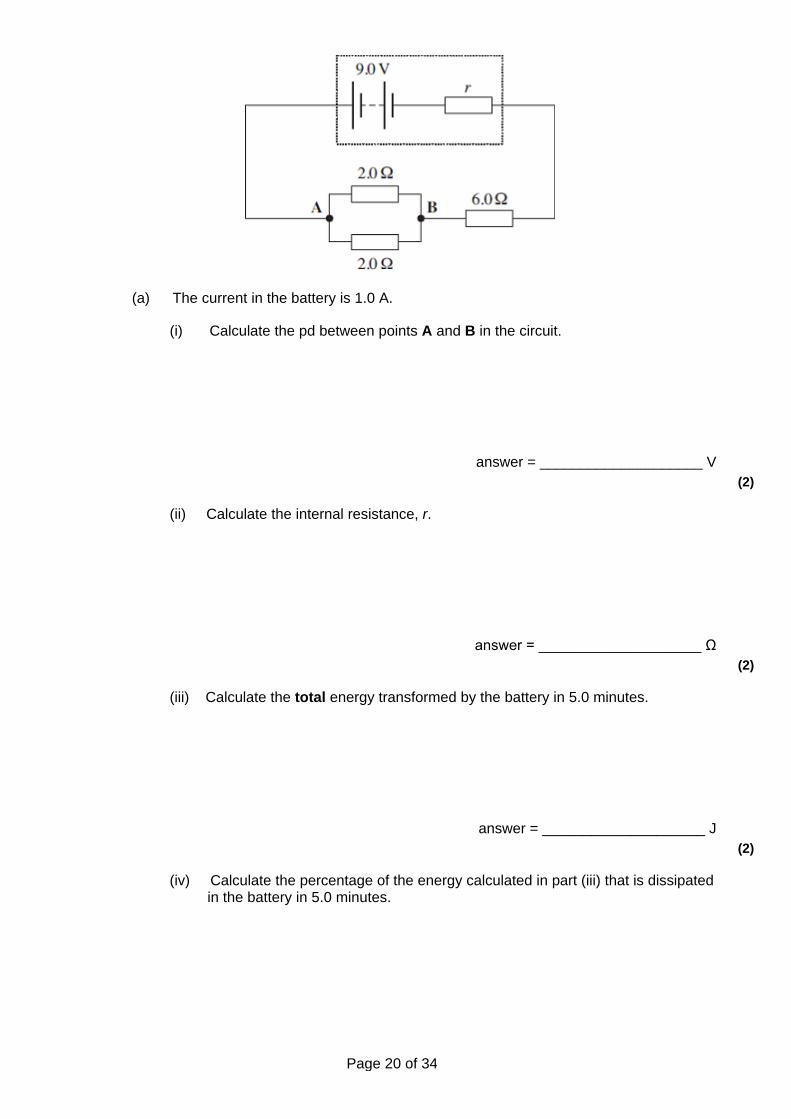
Q17. A battery of emf 9.0 V and internal resistance, r, is connected in the circuit shown in the figure below.
Page 20 of 34
(a) The current in the battery is 1.0 A.
(i) Calculate the pd between points A and B in the circuit.
answer = ____________________ V (2)
(ii) Calculate the internal resistance, r.
answer = ____________________ Ω (2)
(iii) Calculate the total energy transformed by the battery in 5.0 minutes.
answer = ____________________ J (2)
(iv) Calculate the percentage of the energy calculated in part (iii) that is dissipated in the battery in 5.0 minutes.
Page 21 of 34
answer = ____________________ % (2)
(b) State and explain one reason why it is an advantage for a rechargeable battery to have a low internal resistance.
___________________________________________________________________
___________________________________________________________________
___________________________________________________________________
___________________________________________________________________ (2)
(Total 10 marks)
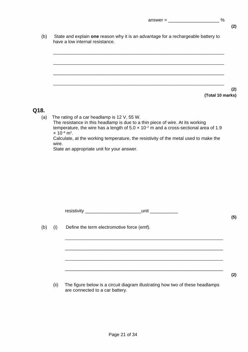
Q18. (a) The rating of a car headlamp is 12 V, 55 W.
The resistance in this headlamp is due to a thin piece of wire. At its working temperature, the wire has a length of 5.0 × 10⁻² m and a cross-sectional area of 1.9 × 10⁻⁸ m2. Calculate, at the working temperature, the resistivity of the metal used to make the wire. State an appropriate unit for your answer.
resistivity ______________________unit ___________ (5)
(b) (i) Define the term electromotive force (emf).
______________________________________________________________
______________________________________________________________
______________________________________________________________
______________________________________________________________ (2)
(ii) The figure below is a circuit diagram illustrating how two of these headlamps are connected to a car battery.

Page 22 of 34
The car battery has an emf of 12 V.
When the switch S is closed there is a current of 9.1 A through the battery and a potential difference of 11.9 V across the headlamps. Calculate the internal resistance of the car battery.
internal resistance ______________________ Ω (2)
(c) A fault develops in one of the headlamps in the figure above causing its resistance to decrease. State and explain how this fault affects the brightness of the other headlamp.
___________________________________________________________________
___________________________________________________________________
___________________________________________________________________
___________________________________________________________________
___________________________________________________________________
___________________________________________________________________ (3)
(Total 12 marks)
Q19. X and Y are two lamps. X is rated at 12 V 36 W and Y at 4.5 V 2.0 W.
(a) Calculate the current in each lamp when it is operated at its correct working voltage.

Page 23 of 34
X ____________________ A
Y ____________________ A (2)
(b) The two lamps are connected in the circuit shown in the figure below. The battery has an emf of 24 V and negligible internal resistance. The resistors, R1 and R2 are chosen so that the lamps are operating at their correct working voltage.
(i) Calculate the pd across R1.
answer ____________________ V (1)
(ii) Calculate the current in R1.
answer ____________________ A (1)
(iii) Calculate the resistance of R1.
answer ____________________ Ω (1)
(iv) Calculate the pd across R2.
answer ____________________ V (1)

Page 24 of 34
(v) Calculate the resistance of R2.
answer ____________________ Ω (1)
(c) The filament of the lamp in X breaks and the lamp no longer conducts. It is observed that the voltmeter reading decreases and lamp Y glows more brightly.
(i) Explain without calculation why the voltmeter reading decreases.
______________________________________________________________
______________________________________________________________
______________________________________________________________ (2)
(ii) Explain without calculation why the lamp Y glows more brightly.
______________________________________________________________
______________________________________________________________
______________________________________________________________ (2)
(Total 11 marks)
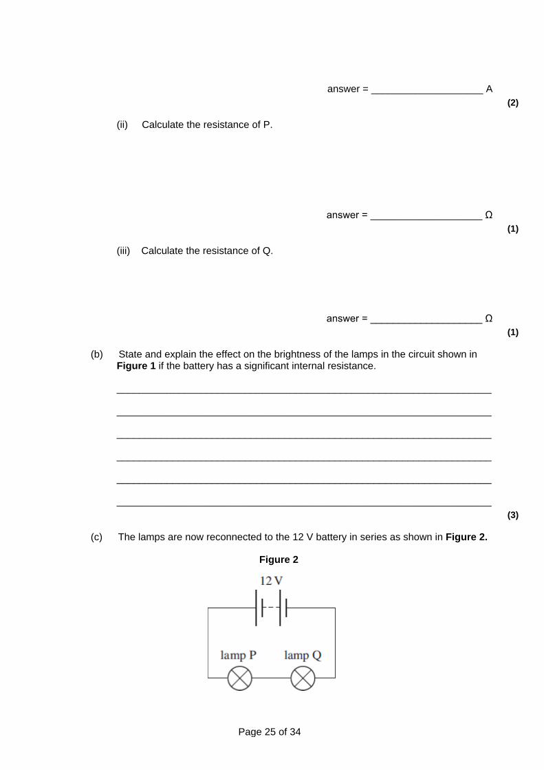
Q20. A battery of negligible internal resistance is connected to lamp P in parallel with lamp Q as shown in Figure 1. The emf of the battery is 12 V.
Figure 1
(a) Lamp P is rated at 12 V 36 W and lamp Q is rated at 12 V 6 W.
(i) Calculate the current in the battery.
Page 25 of 34
answer = ____________________ A (2)
(ii) Calculate the resistance of P.
answer = ____________________ Ω (1)
(iii) Calculate the resistance of Q.
answer = ____________________ Ω (1)
(b) State and explain the effect on the brightness of the lamps in the circuit shown in Figure 1 if the battery has a significant internal resistance.
___________________________________________________________________
___________________________________________________________________
___________________________________________________________________
___________________________________________________________________
___________________________________________________________________
___________________________________________________________________ (3)
(c) The lamps are now reconnected to the 12 V battery in series as shown in Figure 2.
Figure 2

Page 26 of 34
(i) Explain why the lamps will not be at their normal brightness in this circuit.
______________________________________________________________
______________________________________________________________
______________________________________________________________
______________________________________________________________
______________________________________________________________ (2)
(ii) State and explain which of the lamps will be brighter assuming that the resistance of the lamps does not change significantly with temperature.
______________________________________________________________
______________________________________________________________
______________________________________________________________
______________________________________________________________ (3)
(Total 12 marks)
Q21. A battery in a laptop computer has an electromotive force (emf) of 14.8 V and can store a maximum charge of 15. 5 × 10³ C. The battery has negligible internal resistance.
(a) Calculate the maximum amount of energy this battery can deliver.
energy ____________________ J (2)
(b) The average power consumption of the laptop is 30 W.
Estimate how long the laptop can be operated from the fully charged battery. Give your answer in hours.

Page 27 of 34
time ____________________ hours (2)
(Total 4 marks)
Q22. (a) (i) Describe how you would make a direct measurement of the emf ɛ of a cell,
stating the type of meter you would use.
______________________________________________________________
______________________________________________________________ (1)
(ii) Explain why this meter must have a very high resistance.
______________________________________________________________
______________________________________________________________ (1)
(b) A student is provided with the circuit shown in the diagram below.
The student wishes to determine the efficiency of this circuit.
In this circuit, useful power is dissipated in the external resistor. The total power input is the power produced by the battery.
Efficiency =
The efficiency can be determined using two readings from a voltmeter.
(i) Show that the efficiency = where ɛ is the emf of the cell
and V is the potential difference across the external resistor.

Page 28 of 34
(1)
(ii) Add a voltmeter to the diagram and explain how you would use this new circuit to take readings of ɛ and V.
______________________________________________________________
______________________________________________________________
______________________________________________________________ (2)
(c) Describe how you would obtain a set of readings to investigate the relationship between efficiency and the resistance of the external resistor. State any precautions you would take to ensure your readings were reliable.
___________________________________________________________________
___________________________________________________________________
___________________________________________________________________
___________________________________________________________________
___________________________________________________________________
___________________________________________________________________
___________________________________________________________________
___________________________________________________________________ (2)
(d) State and explain how you would expect the efficiency to vary as the value of R is increased.
___________________________________________________________________
___________________________________________________________________
___________________________________________________________________
___________________________________________________________________
___________________________________________________________________
___________________________________________________________________ (2)
(Total 9 marks)
Q23. The circuit diagram below shows a battery of electromotive force (emf) 12 V and internal

Page 29 of 34
resistance 1.5 Ω connected to a 2.0 Ω resistor in parallel with an unknown resistor, R. The battery supplies a current of 4.2 A.
(a) (i) Show that the potential difference (pd) across the internal resistance is 6.3 V.
(1)
(ii) Calculate the pd across the 2.0 Ω resistor.
pd ____________________V (1)
(iii) Calculate the current in the 2.0 Ω resistor.
current ____________________A (1)
(iv) Determine the current in R.
current ____________________ A (1)
(v) Calculate the resistance of R.

Page 30 of 34
R ____________________ Ω (1)
(vi) Calculate the total resistance of the circuit.
circuit resistance ____________________ Ω (2)
(b) The battery converts chemical energy into electrical energy that is then dissipated in the internal resistance and the two external resistors.
(i) Using appropriate data values that you have calculated, complete the following table by calculating the rate of energy dissipation in each resistor.
resistor rate of energy dissipation / W
internal resistance
2.0 Ω
R
(3)
(ii) Hence show that energy is conserved in the circuit.
______________________________________________________________
______________________________________________________________ (2)
(Total 12 marks)
Q24. (a) The power P dissipated in a resistor of resistance R is measured for a range of
values of the potential difference V across it. The results are shown in the table below.
V / V V2 / V2 P / W
1.00 1.0 0.21
1.71 2.9 0.58
2.25 1.01

Page 31 of 34
2.67 1.43
3.00 9.0 1.80
3.27 10.7 2.18
3.50 12.3 2.43
(i) Complete the table above. (1)
(ii) Complete the graph below by plotting the two remaining points and draw a best fit straight line.
(2)
(iii) Determine the gradient of the graph.
gradient = ____________________ (3)
(iv) Use the gradient of the graph to obtain a value for R.
R = ____________________

Page 32 of 34
(1)
(b) The following questions are based on the data in the table above.
(i) Determine the value of R when V = 3.50 V.
R = ____________________ Ω (1)
(ii) The uncertainty in V is ± 0.01 V. The uncertainty in P is ± 0.05 W.

Page 33 of 34
Calculate the percentage uncertainty in the value of R calculated in part (1).
percentage uncertainty = ____________________ % (3)
(iii) Hence calculate the uncertainty in the value of R.
uncertainty = ____________________ (1)
(iv) State and explain whether the value of R you calculated in part (1) is consistent with the value of R you determined from the gradient in part (a)(iv).
(2)
______________________________________________________________
______________________________________________________________
______________________________________________________________
______________________________________________________________
______________________________________________________________
______________________________________________________________ (Total 14 marks)
Q25. In experiments to pass a very high current through a gas, a bank of capacitors of total capacitance 50 µF is charged to 30 kV. If the bank of capacitors could be discharged completely in 5.0 m s what would be the mean power delivered?
A 22 kW
B 110 kW
C 4.5 MW
D 9.0 MW
Page 34 of 34
(Total 1 mark)
Q26. When fully charged the 2.0 mF capacitor used as a backup for a memory unit has a potential difference of 5.0 V across it. The capacitor is required to supply a constant current of 1.0 μA and can be used until the potential difference across it falls by 10%. For how long can the capacitor be used before it must be recharged?
A 10 s
B 100 s
C 200 s
D 1000 s (Total 1 mark)
Q27. A 1 µF capacitor is charged using a constant current of 10 µA for 20 s. What is the energy finally stored by the capacitor?
A 2 × 10⁻³ J
B 2 × 10⁻² J
C 4 × 10⁻² J
D 4 × 10⁻¹ J (Total 1 mark)
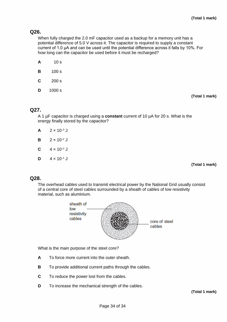
Q28. The overhead cables used to transmit electrical power by the National Grid usually consist of a central core of steel cables surrounded by a sheath of cables of low resistivity material, such as aluminium.
What is the main purpose of the steel core?
A To force more current into the outer sheath.
B To provide additional current paths through the cables.
C To reduce the power lost from the cables.
D To increase the mechanical strength of the cables. (Total 1 mark)


![Basics of Electricity [Siemens]](https://img.dokumen.tips/doc/110x75/552d59804a79593c578b4655/basics-of-electricity-siemens.jpg)