Embed Size (px)
DESCRIPTION
Manual de Operacion y Mantenimiento Turbina Allison 501-KB5 de Rolls Royce.Informacion aplicada a plataforma ABK-N1
Citation preview
PUBLICATION NO. GTP 5341-2D
Operation andMaintenanceManual
Allison Engine Company
MODEL 501-KB5DIGITAL ELECTRICAL CONTROL SYSTEM
PROPRIETARY RIGHTS LEGENDALLISON ENGINE COMPANY
This technical data and the information embodied herein is the property of and proprietary to AllisonEngine Company, and shall not, without prior written permission of Allison Engine Company bedisclosed in whole or in part to third parties. This legend shall be included on any reproduction of thisdata in whole or in part.
“COPYRIGHT - ALLISON ENGINE COMPANY, INC. (unpublished)”
This manual is bailed to the user for a period often (1 O) years from the date on his cover page
The manual, reprints and revisions, both temporary and permanent, remain the property ofAllison Engine Company, Inc. and must be returned upon demand.
#iillJiilJ@f&/ Mmm@Dmm
INITIAL ISSUE : 1 JANUARY 1991
Printed in U.S.A. @ 1995 Allieon Engine Company, Inc,
Allison Engine Company
501-KB5 DEC OPERATION AND MAINTENANCE
IMPORTANT SAFETY NOTICE
IT IS YOUR RESPONSIBILITY to be completely familiar with the warningsand cautions described in this manual. These warnings and cautionsadvise of specific operating and servicing methods that, if notobserved, can result in personal injury, damage to the equipment, orcause the equipment to be un:
It is, however, important toare not exhaustive. Al 1 i sonevaluate and advise the usermight be done or of the possConsequently, Allison Gas Tulevaluation.
Proper methods of operation,
afe.
understand that these warnings and cautionsGas Turbine could not possibly know,of all conceivable ways in which serviceble hazardous consequences of each way.bine has not undertaken any such broad
service, and re~air are imDortant to thesafe, reliable operation of”all equipment. The procedu~es recommendedby Allison Gas Turbine and described in this manual are effectivemethods for performing these operations. Some of these serviceoperations require the use of tools specially designed for the purpose.The special tools should be used when and as recommended. ALLISON GASTURBINE STRONGLY RECOMMENDS THE PROCEDURES HEREIN SHOULD BE USED TO THEEXCLUSION OF OTHERS.
ANYONE WHO USESTURBINE ASSUMES
A PROCEDURE WHICH IS NOT RECOMMENDED BY ALLISON GASTHE RISK OF ANY CONSEQUENCE THAT MIGHT OCCUR.
WARNINGS, CAUTIONS, AND NOTES
The following definitions apply in this manual.
WARNING
A PROCEDURE, PRACTICE, CONDITION, STATEMENT, ETC., WHICH IF NOT STRICTLYOBSERVED, COULD RESULT IN INJURY TO OR DEATH OF PERSONNEL.
CAUTION
A PROCEDURE, PRACTICE, CONDITION, STATEMENT, ETC., WHICH IF NOT STRICTLYOBSERVED, COULD RESULT IN DAMAGE TO OR DESTRUCTION OF THE EQUIPMENT.
NOTE
ng or maintenance procedure, condition, or statement, whichAn essential operatmust be highlighted
JAN/91
. .
WP-1
.
Allison Engine Company
501-KB5 DEC OPERATION AND MAIN ILNANLt
LIST OF WARNINGS
This manual contains the following warnings. IT IS YOUR RESPONSIBILITY to befamiliar with all of them.
AN OPERATING PROCEDURE, PRACTICE, ETC., WHICH IF NOT CORRECTLY FOLLOWED, COULDRESULT IN PERSONAL INJURY OR LOSS OF LIFE.
TRICRESYLPHOSPHATE (TCP) AND SOME OF THE OTHER ADDITIVES IN THE SYNTHETIC OILSARE READILY ABSORBED BY THE SKIN AND ARE HIGHLY TOXIC. ANY PART OF THE BODYTHAT COMES IN CONTACT WITH THESE OILS SHOULD BE CLEANSED AS SOON AS POSSIBLE.
A SOLUTION OF ALODINE, NITRIC ACID, AND WATER IS INJURIOUS TO THE SKIN ANDCLOTHING. OPERATORS MUST BE ADEQUATELY PROTECTED BY GOGGLES, RUBBER GLOVES,APRONS, ETC.
KEEP HANDS OUT OF THE ENGINE. DO NOT TURN THE ENGINE ROTOR BY THE BLADES.DISABLE STARTER CIRCUITS DURING INSPECTION; SEVER INJURY MAY OCCUR.
THE IGNITION SYSTEM MUST BE OFF FOR AT LEAST 5 MINUTES BEFORE HANDLING THEEXCITER. THIS PERIOD OF TIME PERMITS BLEED RESISTORS WITHIN THE EXCITER TODISSIPATE ENERGY STORED IN THE CONDENSERS. SEVER INJURY OR DEATH MAY OCCUR, IFAN ENERGIZED EXCITER IS HANDLED.
AS AN ADDED PRECAUTION TO GET RID OF ANY DANGEROUS ENERGY WHICH COULD PERSISTIF THE BLEED RESISTORS WERE OPEN, SHORT THE CENTER ELECTRODE OF THE HIGHTENSION CONNECTOR TO THE CASE OF THE EXCITER.
THE EXCITER TEST MUST NOT BE PERFORMED IN AN AREA WHERE THERE IS THEPOSSIBILITY OF A FUEL LEAK OR ANY OTHER EXPLOSIVE MATERIAL WHICH COULD BEIGNITED. INJURY OR DAMAGE MAY OCCUR.
NEVER HANDLE AN ENERGIZED IGNITER. MAKE SURE THAT IGNITION SYSTEM HAS BEEN OFFFOR AT LEAST FIVE MINUTES BEFORE REMOVING AN IGNITER. THIS TIME WILL ALLOW THEEXCITER BLEED RESISTORS TO DISSIPATE ALL ENERGY STORED IN THE CONDENSERS.SEVER INJURY OR DEATH MAY OCCUR IF AN ENERGIZED IGNITER IS HANDLED.
BURNING DRAIN LINES MAY BE HOT IF BURNER DRAIN VALVES ARE STUCK OPEN. INJURYMAY OCCUR.
ALWAYS BEND THE LOCKWIRE ENDS IN TOWARDS THE FASTENED ITEM TO GUARD AGAINSTPERSONAL INJURY AND/OR PREVENT POSSIBLE DAMAGE TO ADJACENT PARTS.
NEVER HANDLE AN ENERGIZED IGNITER. SERIOUS PERSONAL INJURY MAY OCCUR FROMCONTACT WITH AN ENERGIZED IGNITER.
THE IGNITER TEST SHOULD NOT BE PERFORMED IN AN AREA WHERE THERE IS THEPOSSIBILITY OF A FUEL LEAK OR ANY OTHER EXPLOSIVE MATERIAL WHICH COULD BEIGNITED. INJURY OR DAMAGE MAY OCCUR.
WP-2 JAN/91
Allison Engine Company
501 -KB5 DEC OPERATION AND MAINTENANCE
LIST OF WARNINGS (cent)
THE IGNITION SYSTEM SHOULD BE OFF AT LEAST 5 MINUTES BEFORE HANDLING THEIGNITION SYSTEM COMPONENTS. SEVER INJURY MAY OCCUR.
SERIOUS PERSONAL INJURY MAY OCCUR IF IGNITION SYSTEM IS ENERGIZED.
USE CARE IN REMOVAL OF AIR VALVE STEM TO PREVENT IT FROM BLOWING OFF ANDCAUSING INJURY TO PERSONNEL.
MAKE SURE ALL PRESSURE IS RELEASED BEFORE REMOVING PIPE PLUG OR CONTAINERCOVER. INJURY OR DAMAGE MAY OCCUR.
MINERAL SPIRITS ARE TOXIC. ANY PART OF THETHESE MINERAL SPIRITS SHOULD BE CLEANSED ASOCCUR.
THE TEMPERATURE RISE THROUGH THE COMPRESSORSEVERE BURNS CAN OCCUR.
PLASTIC GASKET, 56841, MAY BE IRRITATING TOAVOID SKIN CONTACT. IN CASE OF SKIN CONTAC-WATER.
BODY THAT COMES IN CONTACT WITHSOON AS POSSIBLE. INJURY MAY
CAN BE MORE THAN 500” F (260°C) .
THE SKIN. USE AN APPLICATOR TO, REMOVE BY WASHING WITH SOAP AND
MAKE SURE ELECTRICAL POWER IS OFF. DAMAGE OR INJURY MAY OCCUR.
CLEANING SOLVENT FED. SPEC. P-D-680-2 IS TOXIC. PROVIDE ADEQUATE VENTILATION.
THIS SOLUTION IS INJURIOUS TO THE SKIN AND CLOTHING: OPERATORS MUST BEADEQUATELY PROTECTED BY GOGGLES, RUBBER GLOVES, APRONS, ETC.
IF BLEED VALVES ARE NOT CLOSING, THEMAINTENANCE PERSONNEL IF TOUCHED.
MAKE SURE SOLVENT IS DRY BEFORE HEATOCCUR.
BLEED VALVE CAN BE HOT AND CAN BURN
IS APPLIED. INJURY AND/OR DAMAGE MAY
JAN/91 WP-3
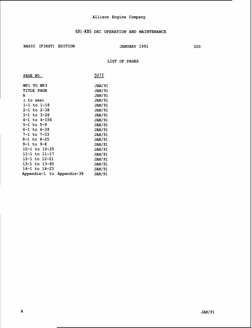
BASIC (FIRST) EDITION
PAGE NO.
WP1 TO WP3TITLE PAGEAi to xxxi1-1 to 1-182-1 to 2-383-1 to 3-284-1 to 4-1565-1 to 5-96-1 to 6-39
Allison Engine Company
501-KB5 DEC OPERATION AND MAINTENANCE
7-1 to 7-338-1 to 8-259-1 to 9-810-1 to 10-2511-1 to 11-1712-1 to 12-2113-1 to 13-6014-1 to 14-23Appendix-1 to Appendix-38
JANUARY 1991
LIST OF PAGES
~
JAN/91JAN/91JAN/91JAN/91JAN/91JAN/91JAN/91JAN/91JAN/91JAN/91JAN/91JAN/91JAN/91JAN/91JAN/91JAN/91JAN/91JAN/91JAN/91
200
A JAN/91
I
Allison Engine Company
501-KB5 DEC OPERATION AND MAINTENANCE
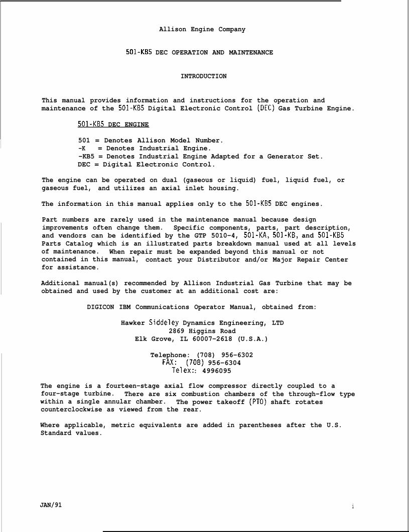
INTRODUCTION
This manual provides information and instructions for the operation andmaintenance of the 501-KB5 Digital Electronic Control (DEC) Gas Turbine Engine.
501-KB5 DEC ENGINE
501 = Denotes Allison Model Number.-K = Denotes Industrial Engine.-KB5 = Denotes Industrial Engine Adapted for a Generator Set.DEC = Digital Electronic Control.
The engine can be operated on dual (gaseous or liquid) fuel, liquid fuel, orgaseous fuel, and utilizes an axial inlet housing.
The information in this manual applies only to the 501-KB5 DEC engines.
Part numbers are rarely used in the maintenance manual because designimprovements often change them. Specific components, parts, part description,and vendors can be identified by the GTP 5010-4, 501-KA, 501-KB, and 501-KB5Parts Catalog which is an illustrated parts breakdown manual used at all levelsof maintenance. When repair must be expanded beyond this manual or notcontained in this manual, contact your Distributor and/or Major Repair Centerfor assistance.
Additional manual(s) recommended by Allison Industrial Gas Turbine that may beobtained and used by the customer at an additional cost are:
DIGICON IBM Communications Operator Manual, obtained from:
Hawker Siddeley Dynamics Engineering, LTD2869 Higgins Road
Elk Grove, IL 60007-2618 (U.S.A.)
Telephone: (708) 956-6302FA;e1:x708) 956-6304
: 4996095
The engine is a fourteen-stage axial flow compressor directly coupled to afour-stage turbine. There are six combustion chambers of the through-flow typewithin a single annular chamber. The power takeoff (PTO) shaft rotatescounterclockwise as viewed from the rear.
Where applicable, metric equivalents are added in parentheses after the U.S.Standard values.
JAN/91 i
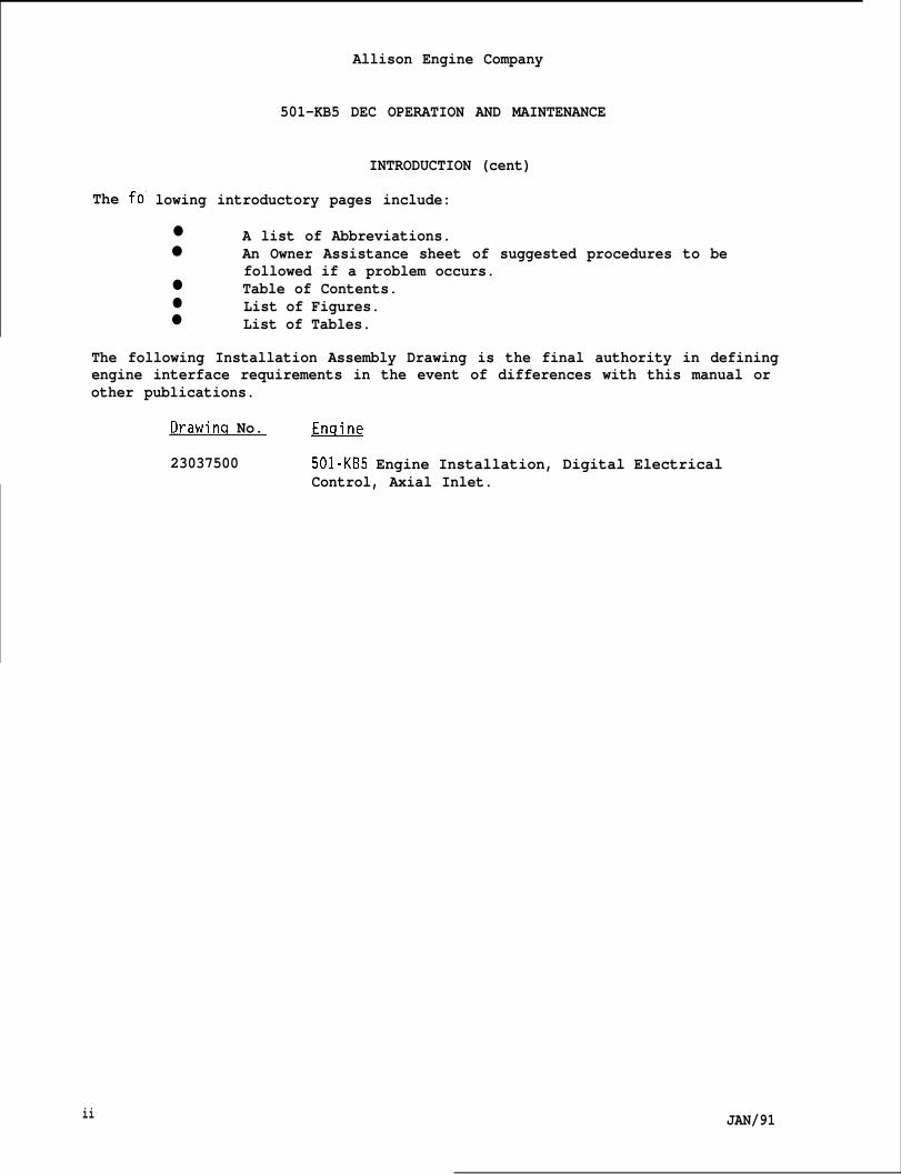
The fo’ lowing introductory pages include:
Allison Engine Company
501-KB5 DEC OPERATION AND MAINTENANCE
INTRODUCTION (cent)
● A list of Abbreviations.● An Owner Assistance sheet of suggested procedures to be
followed if a problem occurs.● Table of Contents.● List of Figures.● List of Tables.
The following Installation Assembly Drawing is the final authority in definingengine interface requirements in the event of differences with this manual orother publications.
Drawinq No. m
23037500 501-KB5 Engine Installation, Digital ElectricalControl, Axial Inlet.
ii JAN/91
Allison Engine Company
501-KB5 DEC OPERATION AND MAINTENANCE
OHNER ASSISTANCE
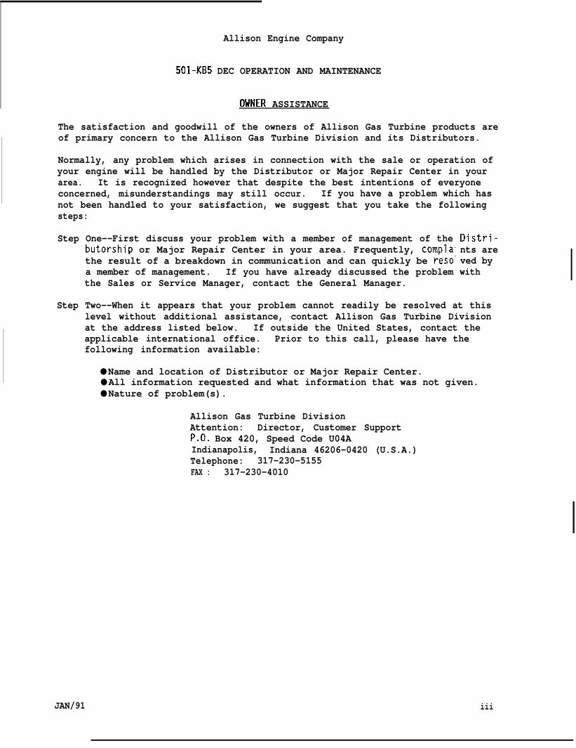
The satisfaction and goodwill of the owners of Allison Gas Turbine products areof primary concern to the Allison Gas Turbine Division and its Distributors.
Normally, any problem which arises in connection with the sale or operation ofyour engine will be handled by the Distributor or Major Repair Center in yourarea. It is recognized however that despite the best intentions of everyoneconcerned, misunderstandings may still occur. If you have a problem which hasnot been handled to your satisfaction, we suggest that you take the followingsteps:
Step One--First discuss your problem with a member of management of thebutorship or Major Repair Center in your area. Frequently, complathe result of a breakdown in communication and can quickly be reso”a member of management. If you have already discussed the problemthe Sales or Service Manager, contact the General Manager.
Distri-nts areved bywith
Step Two--When it appears that your problem cannot readily be resolved at thislevel without additional assistance, contact Allison Gas Turbine Divisionat the address listed below. If outside the United States, contact theapplicable international office. Prior to this call, please have thefollowing information available:
● Name and location of Distributor or Major Repair Center.● All information requested and what information that was not given.● Nature of problem(s).
Allison Gas Turbine DivisionAttention: Director, Customer SupportP.O. Box 420, Speed Code U04AIndianapolis, Indiana 46206-0420 (U.S.A.)Telephone: 317-230-5155FAX : 317-230-4010
JAN/91 iii
Allison Engine Company
501-KB5 DEC OPERATION AND MAINTENANCE
INTERNATIONAL REGIONAL OFFICES
Allison Division of General Motors OverseasDistribution Corporationc/o General Motors ContinentalPostbox No. 9, Noordelaan 75B-2030 Antwerp, BelgiumTelephone: 9-011-32-3-542-0230Telex: 32678
Allison Division of General Motors OverseasDistribution Corporationc/o General Motors France S.A.56/68 Avenue Louis Roche92231 Gennevilliers, FranceTelephone: 9-011-33-1-790-7000Telex: (842) 620050
Allison Division of General Motors OverseasDistribution Corporation15 Benoi SectorJurong TownSingapore 2262Telephone: 9-011-265-65-4697Telex: RS23054
When contacting the Home Office or Regional, please bear in mind that ultimate-ly your problem will likely be resolved at the Distributorship or Major RepairCenters utilizing their facilities, equipment, and personnel. Therefore, it issuggested that you follow the precedinci stet)s in sequence when pursuing aproblem.
Your purchase of an Al~ison Gas Turbine product isAllison’s sincere desire to assist in assuring you
DISTRIBUTORS
CENTRAX LIMITEDGAS TURBINE DIVISIONShaldon Road, Newton AbbotDevon, England TQ124SAMr. R.E. WhelbandGeneral Manager, Product supportTelephone: 44-626-5-2251Telex: 42935Telecopier: 44-626-5-2250
greatly appreciated. It iscomplete satisfaction.
CEC EQUIPMENTS MARITIMOSINDUSTRIALS SAILHA Do Caju, S/NRCEP 24040 Niteroi - RJBrazilMr. George StilgoeTelephone: 55-021-719-2588
55-021-719-4969Telex: 32151 (CES BR)Telecopier: 55-021-719-1392
iv JAN/91
Allison Engine Company
501-KB5 DEC OPERATION AND MAINTENANCE
DISTRIBUTORS (cent)
DETROIT ENGINE AND TURBINECOMPANYP.O. Box 188, Blain AtholAdelaide, South Australia 5084Mr. Trevor SandoEngineering ManagerTelephone: 61-8-260-2299Telex: 82427 (DETCO AA)Telecopier: 61-8-349-4142
TOMINAGA AND COMPANY, LIMITEDShuwa AsakusabashiNishiguchi Building4-2-2, Asakusabashi, Taito-KuTokyo, 111, JapanMr. Y. KatsumiEngineering ManagerTelephone: 81-3-5687-0040Telex: J-22435 (TOMCO JAPAN)Telecopier: 81-3-5687-0147
U.S. TURBINE CORPORATION7685 South State Route 48Mainville, Ohio 45039 (U.S.A.)Mr. David” L. Klue “VP of OperationTelephone: 513-683-6100Telex: 247358Telecopier: 513-683-6939
ENGINEERED PRODUCT SUPPLIER
STEWART & STEVENSON SERVICES16415 S. JacintoportHouston, Texas 77015 (U.S.A.)Mr. Pete WatsonGeneral Manager, Product SupportTelephone: 713-457-7517Telex: 79-4221 (CPW HOU)Telecopier: 713-452-7550
JAN/91 v
Allison Engine Company
501-KB5 DEC OPERATION AND MAINTENANCE
MAJOR REPAIR CENTERS
AVIALL, INC. NATIONAL AIRMOTIVE CORPORATION3111 Kenwood Street 7200 Lockheed Street, Building 815Burbank, California 91505 (U.S.A.) P.O. BOX 6069 (946-0069)Mr. Leroy Johnson Oakland International AirportManager 501-K Industrial Sales and Services Oakland, California 94621 (U.S.A.)Telephone: 818-973-1420 Mr. Tom MorjigTelex: 673281 (AVI BUBK) Director, 501 Industrial SupportTelecopier: 818-567-4200 Telephone: 415-635-1500
Telex: 160750 (AIRENGINE OAKTelecopier: 415-635-3352
STANDARD AERO LIMITED33 Allen Dyne RoadWinnipeg 21, ManitobaCanada R3H lA1Mr. Paul BainbridgeIndustrial Product Line DirectorTelephone: 204-788-2270Telex: 07-57878 (STANDARDO WPG)Telecopier: 204-783-1421
vi JAN/91
I
ALLIGTASPALAMS
ANAssyASTM
AttnaveAWGcC.A.CDPCgCIPCITC/LCPUco.cent.Corp.CR
Allison Engine Company
501-KB5 DEC OPERATION AND MAINTENANCE
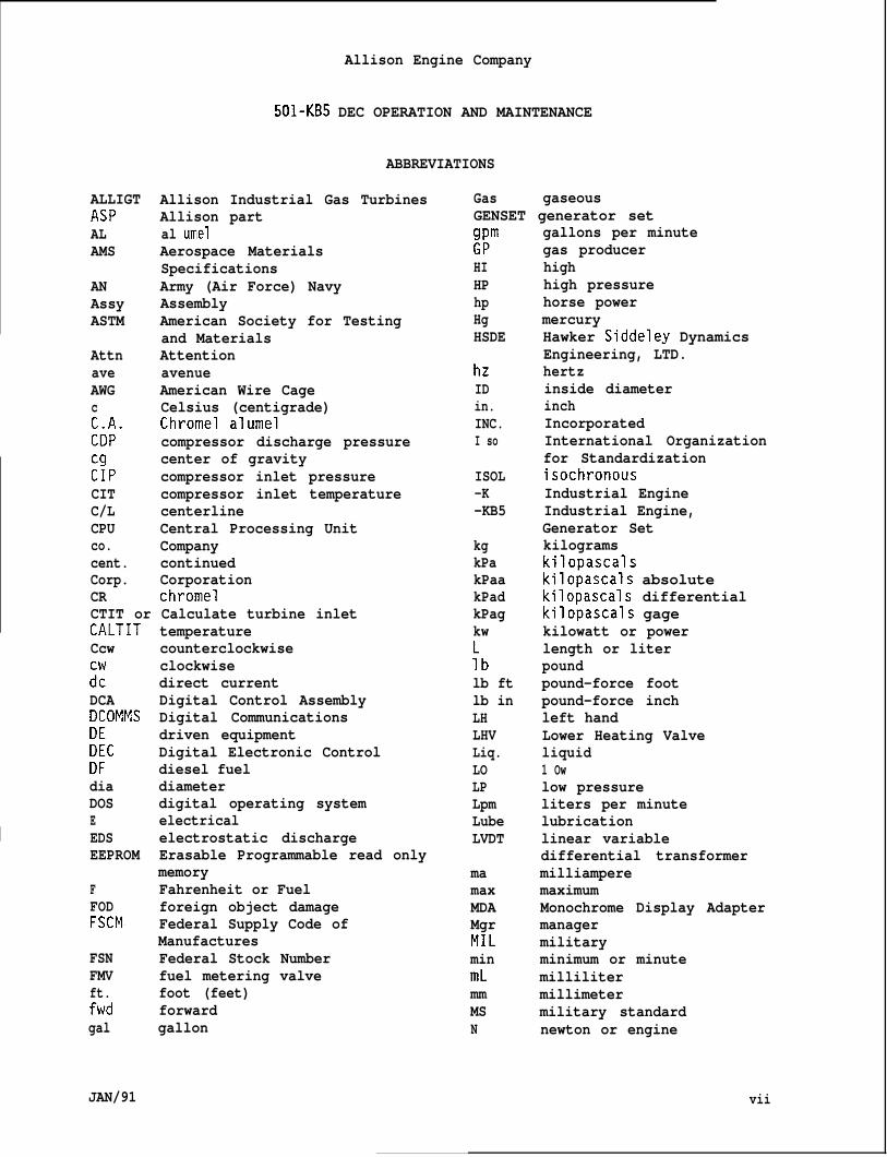
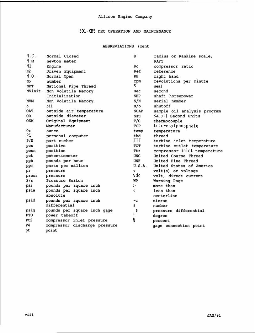
ABBREVIATIONS
Allison Industrial Gas TurbinesAllison partal umelAerospace MaterialsSpecificationsArmy (Air Force) NavyAssemblyAmerican Society for Testingand MaterialsAttentionavenueAmerican Wire CageCelsius (centigrade)Chromel alumelcompressor discharge pressurecenter of gravitycompressor inlet pressurecompressor inlet temperaturecenterlineCentral Processing UnitCompanycontinuedCorporationchromel
CTIT or Calculate turbine inletCALTITCcw
::DCADCOMMS
RcDFdiaDOSEEDSEEPROM
FFODFSCM
FSNFMVft.fwdgal
JAN/91
temperaturecounterclockwiseclockwisedirect currentDigital Control AssemblyDigital Communicationsdriven equipmentDigital Electronic Controldiesel fueldiameterdigital operating systemelectricalelectrostatic dischargeErasable Programmable read onlymemoryFahrenheit or Fuelforeign object damageFederal Supply Code ofManufacturesFederal Stock Numberfuel metering valvefoot (feet)forwardgallon
Gas gaseousGENSET generator set;~m
HIHPhpHgHSDE
hzIDin.INC.I so
ISOL-K-KB5
kgkPakPaakPadkPagkw
;blb ftlb inLHLHVLiq.LOLPLpmLubeLVDT
mamaxMDAMgrMILminmLmmMSN
gallons per minutegas producerhighhigh pressurehorse powermercuryHawker Siddeley DynamicsEngineering, LTD.hertzinside diameterinchIncorporatedInternational Organizationfor StandardizationisochronousIndustrial EngineIndustrial Engine,Generator Setkilogramskilopascalskilopascals absolutekilopascals differentialkilopascals gagekilowatt or powerlength or literpoundpound-force footpound-force inchleft handLower Heating Valveliquid1 Owlow pressureliters per minutelubricationlinear variabledifferential transformermilliamperemaximumMonochrome Display Adaptermanagermilitaryminimum or minutemillilitermillimetermilitary standardnewton or engine
vii
N.C.NomN1N2N.O.No.NPTNVinit
NVMoOATODOEM
OzPcP/NposposnpotpphppmprpressP/spsipsia
psid
psigPTOPt2P4pt
Allison Engine Company
501-KB5 DEC OPERATION AND MAINTENANCE
Normal Closednewton meterEngineDriven EquipmentNormal OpennumberNational Pipe ThreadNon Volatile MemoryInitializationNon Volatile Memoryoil
ABBREVIATIONS (cent
outside air temperatureoutside diameterOriginal EquipmentManufacturerouncepersonal computerpart numberpositivepositionpotentiometerpounds per hourparts per millionpressurepressurePressure Switchpounds per square inchpounds per square inchabsolutepounds per square inchdifferentialpounds per square inch gagepower takeoffcompressor inlet pressurecompressor discharge pressurepoint
R
RcRefRHrpmssecSHPS/Ns/oSOAPSsuT/CTCPtempthdTITTOTTtzUNCUNFU.S.A.vvdcWP><
-u#P
0
%
radius or Rankine scale,RAFTcompressor ratioreferenceright handrevolutions per minutesealsecondshaft horsepowerserial numbershutoffsample oil analysis programSabolt Second Unitsthermocoupletricresylphosphatetemperaturethreadturbine inlet temperatureturbine outlet temperaturecompressor inlet temperatureUnited Coarse ThreadUnited Fine ThreadUnited States of Americavolt(s) or voltagevolt, direct currentWarning Pagemore thanless thancenterlinemicronnumberpressure differentialdegreepercentgage connection point
viii JAN/91
Allison Engine Company
501-KB5 DEC OPERATION AND MAINTENANCE
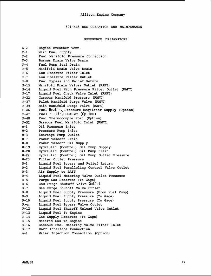
REFERENCE DESIGNATORS
A-2F-1F-2F-3F-4F-5F-6F-7F-8F-15F-16F-17F-22F-37F-39F-46F-47F-48F-52o-10-20-30-70-80-190-200-220-23R-1R-2R-3R-4R-5R-6R-7R-8R-9R-10R-nR-12R-13R-14R-15R-16R-17w-l
JAN/91
Engine Breather Vent.Main Fuel SupplyFuel Manifold Pressure ConnectionBurner Drain Valve DrainFuel Pump Seal DrainManifold Drain Valve DrainLow Pressure Filter InletLow Pressure Filter OutletFuel Bypass and Relief ReturnManifold Drain Valves Outlet (RAPT)Liquid Fuel High Pressure Filter Outlet (RAFT)Liquid Fuel Check Valve Inlet (RAFT)Gaseous Manifold Pressure (RAFT)Pilot Manifold Purge Valve (RAFT)Main Manifold Purge Valve (RAFT)Fuel Heatinq Pressure Regulator Supply (Option)Fuel Heatin~ Outlet (Option)Fuel Thermocouple Port (Option)Gaseous Fuel Manifold Inlet (RAFT)Oil Pressure InletPressure Pump InletScavenge Pump OutletPower Takeoff DrainPower Takeoff Oil SupplyHydraulic (Control) Oil Pump SupplyHydraulic (Control) Oil Pump DrainHydraulic (Control) Oil Pump Outlet PressureFilter Outlet PressureLiquid Fuel Bypass and Relief ReturnLiquid Fuel Paralleling Control Valve OutletAir Supply to RAFTLiquid Fuel Metering Valve Outlet PressurePurge Gas Pressure (To Gage)Gas Purge Shutoff Valve OutletGas Purge Shutoff Valve OutletLiquid Fuel Supply Pressure (From Fuel Pump)Liquid Fuel Supply Pressure (To Gage)Liquid Fuel Supply Pressure (To Gage)Liquid Fuel Bypass Valve OutletLiquid Fuel Shutoff Unload Valve OutletLiquid Fuel To EngineGas Supply Pressure (To Gage)Metered Gas To EngineGaseous Fuel Metering Valve Filter InletRAFT Interface ConnectionWater Injection Connection (Option)
ix
Section
1
x
Allison Engine Company
501-KB5 DEC OPERATION AND MAINTENANCE
REPORTING ERRORS AND RECOMMENDING IMPROVEMENTS
You can help improve this manual. If you find any mistakesor if you know of a way to improve the procedures, pleaselet us know. Fill out and mail form GT 11122 (PublicationChange Request) located in the back of this manual to:
ALLISON GAS TURBINE DIVISIONGeneral Motors CorporationATTN : Publications DepartmentP.O. Box 420 Speed Code: U15Indianapolis, Indiana 46206-0420 (U.S.A.)
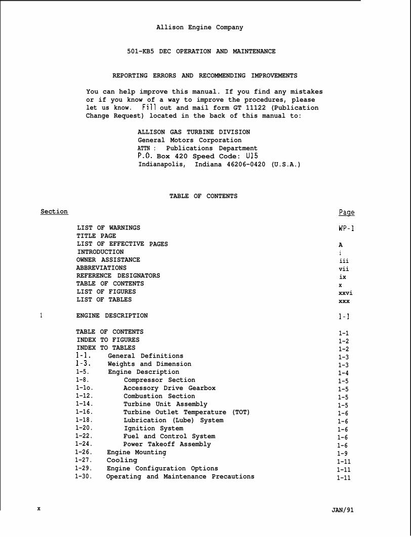
LIST OF WARNINGSTITLE PAGELIST OF EFFECTIVEINTRODUCTIONOWNER ASSISTANCEABBREVIATIONS
TABLE OF CONTENTS
PAGES
REFERENCE DESIGNATORSTABLE OF CONTENTSLIST OF FIGURESLIST OF TABLES
ENGINE DESCRIPTION
TABLE OF CONTENTSINDEX TO FIGURESINDEX TO TABLES
General Definitions;::: Weights and Dimension1-5. Engine Description1-8.1-1o.1-12.1-14.1-16.1-18.1-20.1-22.1-24.
Compressor SectionAccessory Drive GearboxCombustion SectionTurbine Unit AssemblyTurbine Outlet Temperature (TOT)Lubrication (Lube) SystemIgnition SystemFuel and Control SystemPower Takeoff Assembly
1-26. Engine Mounting1-27. Cooling -
1-29. Engine Configuration Options1-30. Operating and Maintenance Precautions
WP-1
Aiiiiviiixxxxvixxx
1-1
1-11-21-21-31-31-41-51-51-51-51-61-61-61-61-61-91-111-111-11
JAN/91
Allison Engine Company
501-KB5 DEC OPERATION AND MAINTENANCE
TABLE OF CONTENTS
Section
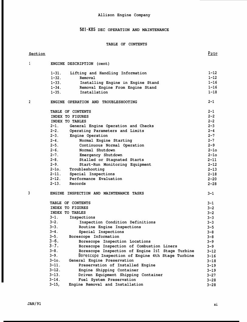
1 ENGINE DESCRIPTION (cent)
1-31. Lifting and Handling Information1-32. Removal1-33. Installing Engine in Engine Stand1-34. Removal Engine From Engine Stand1-35. Installation
2 ENGINE OPERATION AND TROUBLESHOOTING
TABLE OF CONTENTSINDEX TO FIGURESINDEX TO TABLES2-1. General Engine Operation and Checks2-2. Operating Parameters and Limits2-3. Engine Operation2-4. Normal Engine Starting2-5. Continuous Normal Operation2-6. Normal Shutdown2-7. Emergency Shutdown2-8. Stalled or Stagnated Starts2-9. Start-Run Monitoring Equipment2-1o. Troubleshooting2-11. Special Inspections2-12. Performance Evaluation2-13. Records
3 ENGINE INSPECTION AND MAINTENANCE TASKS
TABLE OF CONTENTSINDEX TO FIGURESINDEX TO TABLES3-1.3-2.3-3.3-4.3-5.
;:;:3-8.3-9.3-1o.3-11.3-12.3-13.3-14.3-15,
InspectionsInspection Condition DefinitionsRoutine Engine InspectionsSpecial Inspections
Borescope InformationBorescope Inspection LocationsBorescope Inspection of Combustion LinersBorescope Inspection of Engine lst” Stage TurbineBorescope Inspection of Engine 4th Stage Turbine
General Engine PreservationPreservation of Installed EngineEngine Shipping ContainerDriven Equipment Shipping ContainerFuel System Preservation
Engine Removal and Installation
&
1-121-121-161-161-18
2-1
2-12-22-22-32-42-72-72-92-1o2-1o2-112-122-132-182-202-28
3-1
3-13-23-23-33-33-53-83-83-93-93-123-163-183-193-193-273-283-28
JAN/91 xi
501-KB5
Section
4 FUEL SYSTEM
TABLE OF CONTENTSINDEX TO FIGURESINDEX TO TABLES4-1.4-2.4-3.
u:4-6.4-7.4-8.4-9.4-1o.4-11.4-12.4-13.4-14.4-15.4-16.4-17.4-18.4-19.4-20.4-21.4-22.4-234-24.4-25.4-26.4-27.4-28.4-29.4-30.4-31.4-32.4-33.4-34.4-35.4-36.4-37.4-38.4-39.4-40.4-41.4-42.4-43.
Allison Engine Company
DEC OPERATION AND MAINTENANCE
TABLE OF CONTENTS (cent)
&
4-1
4-14-84-1o
Fuel SystemsGaseous Fuel System
Description and OperationFuel Metering Valve (FMV)
Description and OperationRemovalCleaningInspection and TestRepairInstallationInstalled Test and Adjustment
Fuel NozzleDescription and OperationTroubleshootingRemovalInspectionCleaningInstallation
Final FilterDescription and OperationRemovalInstallation
Fuel Manifold and HosesDescription and OperationRemovalInstallation
Gaseous Fuel Water InjectionDescription and OperationDual Fuel Nozzle
Description and OperationTroubleshootingRemovalInspectionCleaningInstallation
Single Entry Liquid Fuel SystemDescriptionOperationFuel Pump
Description and OperationRemovalInstallationTroubleshooting
4-114-114-114-124-124-144-144-154-154-164-164-174-174-174-174-184-184-204-204-204-204-224-224-224-224-234-234-234-234-234-244-254-264-264-274-274-274-284-284-284-334-354-36
xii JAN/91
Allison Engine Company
501-KB5 DEC OPERATION AND MAINTENANCE
TABLE OF CONTENTS (cent,
Section
4 FUEL SYSTEM (cent)
JAN/91
4-44.4-45.4-46.4-47.4-48.4-49.4-50.4-51.4-52.4-53.4-54.4-55.4-56.4-57.4-58.4-59.4-60.4-61.4-62.4-63.4-64.4-65.4-66.4-67.
High Pressure (HP) Fuel FilterDescription and OperationRemovalInstallationFilter Element RemovalCleaningFilter Element Installation
Paralleling ValveDescription and OperationRemovalInstallation
Low Pressure (LP) Fuel FilterDescription and OperationFuel Filter Element RemovalFuel Filter Element InstallationDifferent Pressure Switch RemovalDifferent Pressure Switch InstallationLP Fuel Filter RemovalLP Fuel Filter Installation
Pressure Relief ValveDescription and OperationRemovalInstallation
Fuel Metering Valve (FMV)4-68.4-69.4-70.4-71. Fue”4-72.4-73.4-74.4-75.4-76.4-77.4-78.4-79.4-80.4-81.4-82.4-83.4-84.4-85.4-86.4-87.
Descript~on and OperationRemovalInstallationShutoff Valve
Description and OperationInspectionRemovalInstallation
Manifold Drain ValveDescription and OperationRemovalInstallationInspection and Test
Burner Drain ValvesDescription and OperationRemovalMaintenance and InspectionInstallationTroubleshooting
Fuel Lines and Hoses
PacJ_e
4-364-364-364-374-374-384-414-414-414-424-424-434-434-444-444-474-484-504-514-534-534-534-544-564-564-564-574-604-604-604-614-624-634-634-634-634-644-654-654-654-654-664-674-67
xiii
Allison Engine Company
501-KB5 DEC OPERATION AND MAINTENANCE
TABLE OF CONTENTS (cent)
Section ~
4 FUEL SYSTEM (cent)
4-88.4-89.4-90.4-91.4-92.4-93.4-94.4-95.4-96.4-97.4-98,4-99.4-1oo.4-101.4-102.4-103.4-104.4-105.4-106.4-107.4-108.4-109.4-110.4-111.4-112.4-113.4-114.4-115.4-116.4-117.4-118.4-119.4-120.4-121”.4-122.4-123.4-124.4-125.4-126.4-127.4-128.4-129.4-130.4-131.4-132.
xiv
Single Entry Fuel Nozzle (Fuel Nozzle)Description and OperationRemovalInspectionCleaningInstallation
Liquid Fuel Water InjectionDescription and OperationFlow Divider Valve
Description and OperationRemovalMaintenanceInstallation
Manifold DrainValvesDescription and OperationPilot Manifold Drain Valve RemovalPilot Manifold Drain Valve InstallationMain Manifold Drain Valve RemovalMain Manifold Drain Valve Installation
Liquid Fuel NozzleDescription and OperationRemovalInspectionCleaningInstallation
Fuel Manifold (Pilot and Main)Description and OperationRemoval and Installation
Dual Entry Fuel SystemDescriptionOperationFuel PumpHigh Pressure (HP) Fuel FilterParalleling ValveLow Pressure (LP) Fuel FilterPressure Relief ValveFuel Metering Valve (FMV)Fuel Shutoff ValveFlow Divider ValveBurner Drain ValvesFuel Lines and HosesFuel Manifolds (Pilot and Main)Fuel Nozzles (Dual Entry)
Description and OperationRemoval
4-674-674-684-704-704-724-734-734-734-734-744-744-774-774-774-804-804-814-824-824-824-834-844-844-864-864-864-874-874-874-884-884-884-914-914-914-914-914-914-914-924-924-924-924-93
JAN/91
Allison Engine Company
501-KB5 DEC OPERATION AND MAINTENANCE
TABLE OF CONTENTS (cent)
Section
4 FUEL SYSTEM (cent)
4-133.4-134,4-135.4-136.4-137.4-138.4-139.4-1400
4-141.4-142.4-143.4-144.4-145.4-146.4-147.4-148.4-149.4-150.4-151.4-152.4-153.4-154.4-155.4-156.4-157.4-158.4-159.4-160.4-161.4-162.4-163.4-164.4-165.4-166.4-167.4-168.4-169.4-170.4-171.4-172.4-173.4-174.4-175.4-176.4-177.4-178.
JAN/91
InspectionCleaningInstallation
Manifold Drain ValvesDescription and OperationRemovalInstallation
Dual Entry Fuel Water Injection SystemDescription and Operation
Dual Fuel SystemDescription and OperationLow Pressure (LP) Fuel Filter Assembly
Description and OperationFilter Element RemovalFilter Element InstallationRemovalInstallation
High Pressure (HP) Fuel Filter AssemblyDescription and OperationFilter Element RemovalCleaningFilter Element InstallationRemovalInstallation
Liquid Fuel PumpDescription and OperationRemovalInstallation
Liquid Fuel Metering Valve (FMV)Description and OperationRemovalInstallation
Liquid Fuel Shutoff ValveDescription and OperationRemovalInstallation
Liquid Fuel Shutoff Valve (Ball Type)Description and OperationRemovalInstallation
Flow Divider ValveDescription and OperationRemovalInstallation
Manifold Drain Valves (Pilot and Main)Description and Operation
4-944-954-964-974-974-984-984-984-984-984-984-994-994-994-1oo4-1034-1034-1064-1064-1064-1064-1064-1064-1074-1074-1074-1074-1084-1094-1094-1094-1144-1154-1154-1154-1164-1164-1164-1174-1184-1184-1184-1194-1224-1234-123
xv
MJ1-KB5
Allison Engine Company
DEC OPERATION AND”iiAINTENANCE
TABLE OF CONTENTS (cent)
Section
4 FUEL SYSTEM (cent)
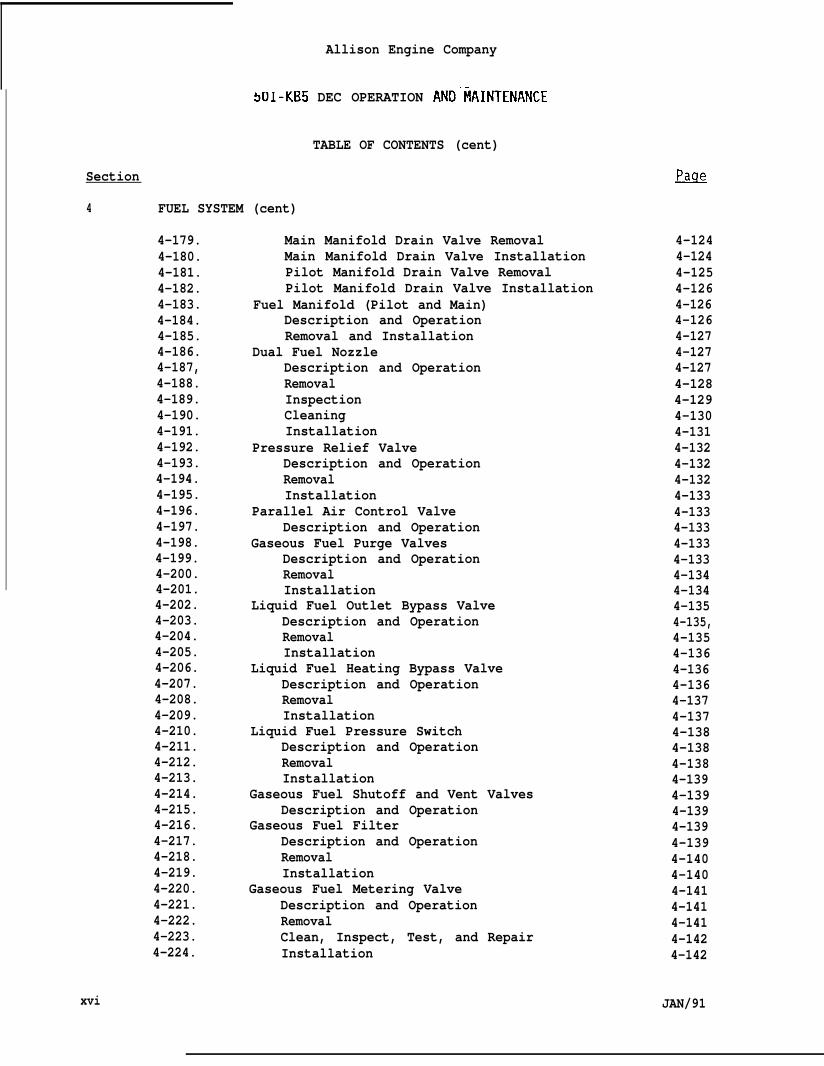
4-179.4-180.4-181.4-182.4-183.4-184.4-185.4-186.4-187,4-188.4-189.4-190.4-191.4-192.4-193.4-194.4-195.4-196.4-197.4-198.4-199.4-200.4-201.4-202.4-203.4-204.4-205.4-206.4-207.4-208.4-209.4-210.4-211.4-212.4-213.4-214.4-215.4-216.4-217.4-218.4-219.4-220.4-221.4-222.4-223.4-224.
Main Manifold Drain Valve RemovalMain Manifold Drain Valve InstallationPilot Manifold Drain Valve RemovalPilot Manifold Drain Valve Installation
Fuel Manifold (Pilot and Main)Description and OperationRemoval and Installation
Dual Fuel NozzleDescription and OperationRemovalInspectionCleaningInstallation
Pressure Relief ValveDescription and OperationRemovalInstallation
Parallel Air Control ValveDescription and Operation
Gaseous Fuel Purge ValvesDescription and OperationRemovalInstallation
Liquid Fuel Outlet Bypass ValveDescription and OperationRemovalInstallation
Liquid Fuel Heating Bypass ValveDescription and OperationRemovalInstallation
Liquid Fuel Pressure SwitchDescription and OperationRemovalInstallation
Gaseous Fuel Shutoff and Vent ValvesDescription and Operation
Gaseous Fuel FilterDescription and OperationRemovalInstallation
Gaseous Fuel Metering ValveDescription and OperationRemovalClean, Inspect, Test, and RepairInstallation
4-1244-1244-1254-1264-1264-1264-1274-1274-1274-1284-1294-1304-1314-1324-1324-1324-1334-1334-1334-1334-1334-1344-1344-1354-135,4-1354-1364-1364-1364-1374-1374-1384-1384-1384-1394-1394-1394-1394-1394-1404-1404-1414-1414-1414-1424-142
xvi JAN/91
Allison Engine company
5cJ1-KB5 DEC OPERATION AND MAINTENANCE
TABLE OF CONTENTS (cent)
Section
4 FUEL SYSTEM (cent)
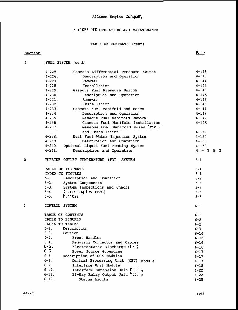
4-225. Gaseous Differential Pressure Switch4-226. Description and Operation4-227. Removal4-228. Installation4-229. Gaseous Fuel Pressure Switch4-230. Description and Operation4-231. Removal4-232. Installation4-233. Gaseous Fuel Manifold and Hoses4-234. Description and Operation4-235. Gaseous Fuel Manifold Removal4-236. Gaseous Fuel Manifold Installation4-237. Gaseous Fuel Manifold Hoses Remova”
and Installation4-238. Dual Fuel Water Injection System4-239. Description and Operation4-240. Optional Liquid Fuel Heating System4-241. Description and Operation
5 TURBINE OUTLET TEMPERATURE (TOT) SYSTEM
TABLE OF CONTENTSINDEX TO FIGURES5-1. Description and Operation5-2. System Components5-3. System Inspections and Checks5-4. I%;i%;gouples (T/C)5-5.
6 CONTROL SYSTEM
TABLE OF CONTENTSINDEX TO FIGURESINDEX TO TABLES6-1. Description6-2. Caution6-3. Front Handles6-4. Removing Connector and Cables
Electrostatic Discharge (ESD)::2: Power Source Grounding6-7. Description of DCA Modules6-8. Central Processing Unit (CPU)6-9. Interface Unit Module6-10. Interface Extension Unit Modu’6-11. 16-Way Relay Output Unit Modu”6-12. Status Lights
~
4-1434-1434-1444-1444-1454-1454-1464-1464-1474-1474-1474-148
4-1504-1504-1504-1504 - 1 5 0
5-1
5-15-15-25-35-35-55-8
6-1
6-16-26-26-36-166-166-166-166-176-17
Module 6-176-18
e 6-22e 6-22
6-25
xviiJAN/91
Allison Engine Company
501-KB5 DEC OPERATION AND MAINTENANCE
TABLE OF CONTENTS (cent)
Section
6 CONTROL SYSTEM (cent)
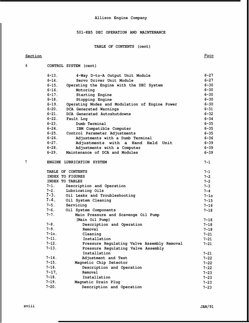
6-13. 4-Way D-to-A Output Unit Module6-14. Servo Driver Unit Module6-15. Operating the Engine with the DEC System6-16. Motoring6-17. Starting Engine6-18. Stopping Engine6-19. Operating Modes and Modulation of Engine Power6-20. DCA Generated Warnings6-21. DCA Generated Autoshutdowns6-22. Fault Log6-23. Dumb Terminal6-24. IBM Compatible Computer6-25. Control Parameter Adjustments6-26. Adjustments with a Dumb Terminal6-27. Adjustments with a Hand Held Unit6-28. Adjustments with a Computer6-29. Maintenance of DCA and Modules
7 ENGINE LUBRICATION SYSTEM
TABLE OF CONTENTSINDEX TO FIGURESINDEX TO TABLES7-1.7-2.
;:::7-5.7-6.7-7.
7-8.7-9.7-1o.7-11.7-12.7-13.
7-14.7-15.7-16.7-170
7-18.7-19.7-20.
xviii
Description and OperationLubricating OilsOil Leaks and TroubleshootingOil System CleaningServicingOil System Components
Main Pressure and Scavenge Oil Pump(Main Oil Pump)
Description and OperationRemovalCleaningInstallationPressure Regulating Valve Assembly RemovalPressure Regulating Valve AssemblyInstallationAdjustment and Test
Magnetic Chip DetectorDescription and OperationRemovalInstallation
Magnetic Drain PlugDescription and Operation
~
6-276-276-306-306-306-306-306-316-326-346-356-356-356-366-396-396-39
7-1
7-17-27-27-37-47-1o7-157-167-18
7-187-187-187-217-217-21
7-217-227-227-227-237-237-237-23
JAN/91
Allison Engine Company
501-KB5 DEC OPERATION AND MAINTENANCE
TABLE OF CONTENTS (cent)
Section ~
7 ENGINE LUBRICATION SYSTEM (cent)
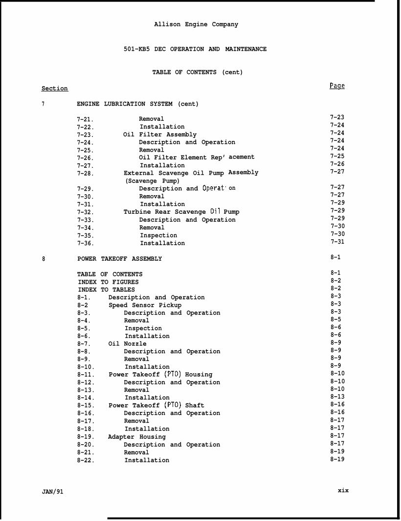
7-21. Removal 7-237-22. Installation 7-247-23. Oil Filter Assembly 7-247-24. Description and Operation 7-247-25. Removal7-26. Oil Filter Element Rep’7-27. Installation7-28. External Scavenge Oil Pump
(Scavenge Pump)7-29. Description and Operat7-30. Removal7-31. Installation7-32. Turbine Rear Scavenge Oil Pump7-33. Description and Operation7-34. Removal7-35. Inspection7-36. Installation
7-24acement 7-25
7-26Assembly 7-27
on 7-277-277-29
8 POWER TAKEOFF ASSEMBLY
TABLE OF CONTENTSINDEX TO FIGURESINDEX TO TABLES8-1.8-28-3.8-4.8-5.8-6.8-7.8-8.8-9.8-10.8-11.8-12.8-13.8-14.8-15.8-16.8-17.8-18.8-19.8-20.8-21.8-22.
Description and OperationSpeed Sensor Pickup
Description and OperationRemovalInspectionInstallation
Oil NozzleDescription and OperationRemovalInstallation
Power Takeoff (PTO) HousingDescription and OperationRemovalInstallation
Power Takeoff (PTO) ShaftDescription and OperationRemovalInstallation
Adapter HousingDescription and OperationRemovalInstallation
7-297-297-307-307-31
8-1
8-18-28-28-38-38-38-58-68-68-98-98-98-98-108-108-108-138-168-168-178-178-178-178-198-19
JAN/91 xix
Allison Engine Company
501-KB5 DEC OPERATION AND MAINTENANCE
TABLE OF CONTENTS (cent)
Section
8 POWER TAKEOFF ASSEMBLY (cent)
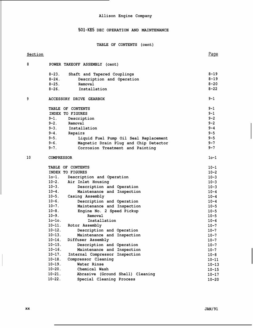
8-23. Shaft and Tapered Couplings8-24. Description and Operation8-25. Removal8-26. Installation
9 ACCESSORY DRIVE GEARBOX
TABLE OF CONTENTSINDEX TO FIGURES9-1. Description9-2. Removal9-3. Installation9-4. Repairs9-5. Liquid Fuel Pump Oil Seal Replacement9-6. Magnetic Drain Plug and Chip Detector9-7. Corrosion Treatment and Painting
10 COMPRESSOR
TABLE OF CONTENTSINDEX TO FIGURES1o-1. Description and Operation10-2. Air Inlet Housing10-3. Description and Operation10-4. Maintenance and Inspection10-5. Casing Assembly10-6. Description and Operation10-7. Maintenance and Inspection10-8. Engine No. 2 Speed Pickup10-9. Removal1o-1o. Installation10-11. Rotor Assembly10-12. Description and Operation10-13. Maintenance and Inspection10-14. Diffuser Assembly10-15. Description and Operation10-16. Maintenance and Inspection10-17. Internal Compressor Inspection10-18. Compressor Cleaning10-19. Water Rinse10-20. Chemical Wash10-21. Abrasive (Ground Shell) Cleaning10-22. Special Cleaning Process
PacJ_e
8-198-198-208-22
9-1
9-19-19-29-29-49-59-59-79-7
1o-1
10-110-210-310-310-310-410-410-410-510-510-510-610-710-710-710-710-710-710-810-1110-1310-1510-1710-20
xx JAN/91
Section
11
12
JAN/91
Allison Engine Company
501-KB5 DEC OPERATION AND MAINTENANCE
TABLE OF CONTENTS (cent)
COMPRESSOR AIR BLEED SYSTEM
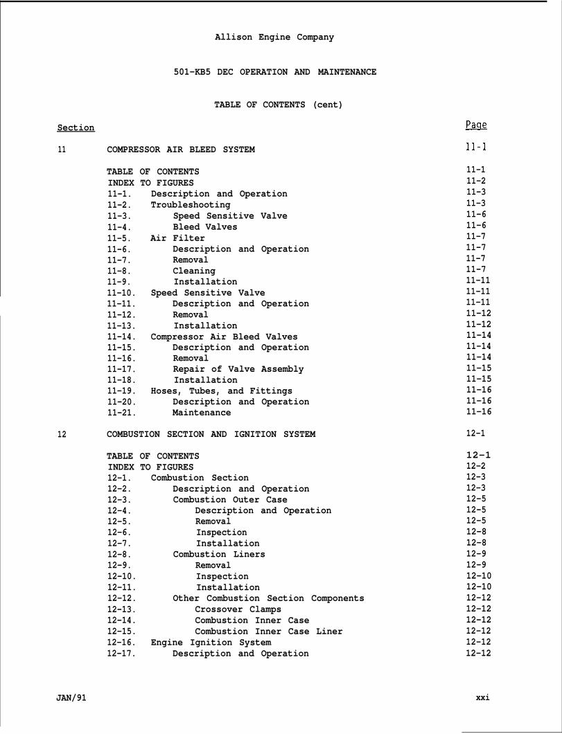
TABLE OF CONTENTSINDEX TO FIGURES11-1. Description and Operation11-2. Troubleshooting11-3. Speed Sensitive Valve11-4. Bleed Valves11-5. Air Filter11-6. Description and Operation11-7. Removal11-8. Cleaning11-9. Installation11-10. Speed Sensitive Valve11-11. Description and Operation11-12. Removal11-13. Installation11-14. Compressor Air Bleed Valves11-15. Description and Operation11-16. Removal11-17. Repair of Valve Assembly11-18. Installation11-19. Hoses, Tubes, and Fittings11-20. Description and Operation11-21. Maintenance
COMBUSTION SECTION AND IGNITION SYSTEM
TABLE OF CONTENTSINDEX TO FIGURES12-1. Combustion Section12-2. Description and Operation12-3. Combustion Outer Case12-4. Description and Operation12-5. Removal12-6. Inspection12-7. Installation12-8. Combustion Liners12-9. Removal12-10. Inspection12-11. Installation12-12. Other Combustion Section Components12-13. Crossover Clamps12-14. Combustion Inner Case12-15. Combustion Inner Case Liner12-16. Engine Ignition System12-17. Description and Operation
11-111-211-311-311-611-611-711-711-711-711-1111-1111-1111-1211-1211-1411-1411-1411-1511-1511-1611-1611-16
12-1
12-112-212-312-312-512-512-512-812-812-912-912-1012-1012-1212-1212-1212-1212-1212-12
xxi
Allison Engine Company
501-KB5 DEC OPERATION AND MAINTENANCE
TABLE OF CONTENTS (cent)
Section
12 COMBUSTION SECTION AND IGNITION SYSTEM (cent)
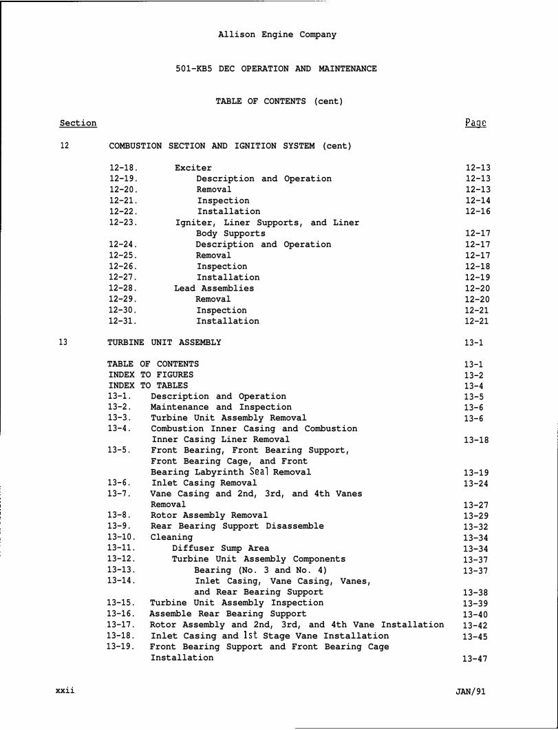
12-18. Exciter12-19. Description and Operation12-20. Removal12-21. Inspection12-22. Installation12-23. Igniter, Liner Supports, and Liner
Body Supports12-24. Description and Operation12-25. Removal12-26. Inspection12-27. Installation12-28. Lead Assemblies12-29. Removal12-30. Inspection12-31. Installation
13 TURBINE UNIT ASSEMBLY
TABLE OF CONTENTSINDEX TO FIGURESINDEX TO TABLES13-1.13-2.13-3.13-4.
13-5.
13-6.13-7.
13-8.13-9.13-10.13-11.13-12.13-13.13-14.
13-15.13-16.13-17.13-18.13-19.
Description and OperationMaintenance and InspectionTurbine Unit Assembly RemovalCombustion Inner Casing and CombustionInner Casing Liner RemovalFront Bearing, Front Bearing Support,Front Bearing Cage, and FrontBearing Labyrinth Seal RemovalInlet Casing RemovalVane Casing and 2nd, 3rd, and 4th VanesRemovalRotor Assembly RemovalRear Bearing Support DisassembleCleaning
Diffuser Sump AreaTurbine Unit Assembly Components
Bearing (No. 3 and No. 4)Inlet Casing, Vane Casing, Vanes,and Rear Bearing Support
Turbine Unit Assembly InspectionAssemble Rear Bearing SupportRotor Assembly and 2nd, 3rd, and 4th Vane InstallationInlet Casing and 1st Stage Vane InstallationFront Bearing Support and Front Bearing CageInstallation
~
12-1312-1312-1312-1412-16
12-1712-1712-1712-1812-1912-2012-2012-2112-21
13-1
13-113-213-413-513-613-6
13-18
13-1913-24
13-2713-2913-3213-3413-3413-3713-37
13-3813-3913-4013-4213-45
13-47
xxii JAN/91
Section
13 TURBINE
13-20.
13-21.13-22.13-23.
13-24.13-25.13-26.
14 GENERAL
Allison Engine Company
501-KB5 DEC OPERATION AND MAINTENANCE
TABLE OF CONTENTS (cent)
UNIT ASSEMBLY (cent)
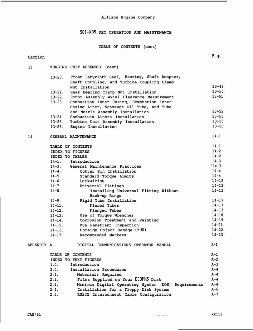
Front Labyrinth Seal, Bearing, Shaft Adapter,Shaft Coupling, and Turbine Coupling ClampNut InstallationRear Bearing Clamp Nut InstallationRotor Assembly Axial Clearance MeasurementCombustion Inner Casing, Combustion InnerCasing Liner, Scavenge Oil Tube, and Tubeand Nozzle Assembly InstallationCombustion Liners InstallationTurbine Unit Assembly InstallationEngine Installation
MAINTENANCE
13-4813-5013-51
13-5213-5313-5513-60
14-1
TABLE OF CONTENTS 14-1INDEX TO FIGURES 14-2INDEX TO TABLES 14-214-1.14-3.14-4.14-5.14-6.14-7.14-8.
14-9.14-11.14-12.14-13.14-14.14-15.14-16.14-17.
APPENDIX A
IntroductionGeneral Maintenance Practices
Cotter Pin InstallationStandard Torque LimitsLockwiringUniversal Fittings
Installing Universal Fitting WithoutBack-up Rings
Rigid Tube InstallationFlared TubesFlanged Tubes
Use of Torque WrenchesCorrosion Treatment and PaintingDye Penetrant InspectionForeign Object Damage (FOD)Recommended Markers
DIGITAL COMMUNICATIONS OPERATOR MANUAL
14-3‘14-314-414-414-1214-1314-13
14-1714-1714-1714-1814-1914-2114-2214-23
A-1
TABLE OF CONTENTS A-1INDEX TO TEXT FIGURES A-21.0. Introduction A-32.0. Installation Procedures A-42.1. Materials Required A-42.2. Files Supplied on Your DCOMMS Disk A-42.3. Minimum Digital Operating System (DOS) Requirements A-42.4. Installation for a Floppy Disk System A-62.5. RS232 Interconnect Cable Configuration A-7
JAN/91 . . . . . . xxiii
Section
APPENDIX A
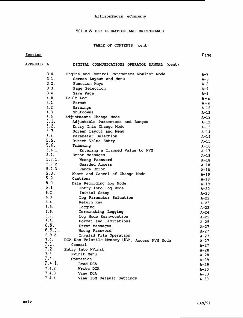
3.0.3.1.3.2.3.3.3.4.4.0.4.1.4.2.4.3.5.0.5.1.
2:::5.4.
;:::5.6.1,5.7.5.7.1.5.7.2.5.7.3.
;:;:
;:!:6.2.6.3.6.4.6.5.6.6.6.7.6.8.
::::106.9.2.7.0.
;:;:7.3.
%.7.4.2.7.4.3.7.4.4.
xxiv
AllisonEngin eCompany
501-KB5 DEC OPERATION AND MAINTENANCE
TABLE OF CONTENTS (cent)
DIGITAL COMMUNICATIONS OPERATOR MANUAL (cent)
Engine and Control Parameters Monitor ModeScreen Layout and MenuFunction KeysPage SelectionSave Page
Fault LogFormatWarningsShutdowns
Adjustments Change ModeAdjustable Parameters and RangesEntry Into Change ModeScreen Layout and MenuParameter SelectionDirect Value EntryTrimming
Entering a Trimmed Value to NVMError Messages
Wrong PasswordGuarded AccessRange Error
Abort and Cancel of Change ModeCautionsData Recording Log Mode
Entry Into Log ModeInitial SetupLog Parameter SelectionReturn KeyLoggingTerminating LoggingLog Mode ReinvocationFormat and LimitationsError MessagesWrong PasswordInvalid File Operation
DCA Non Volatile Memory (NVMGeneral
Entry Into NVinitNVinit MenuOperation
Read DCAWrite DCAView DCAView IBM Default Settings
Access NVM Mode
~
A-7A-8A-8A-9A-9A-nA-nA-12A-12A-12A-12A-13A-14A-14A-15A-16A-17A-18A-18A-18A-18A-19A-19A-19A-20A-20A-22A-23A-23A-24A-25A-25A-27A-27A-27A-27A-27A-28A-28A-29A-29A-30A-30A-30
JAN/91
“1
APPENDIX A
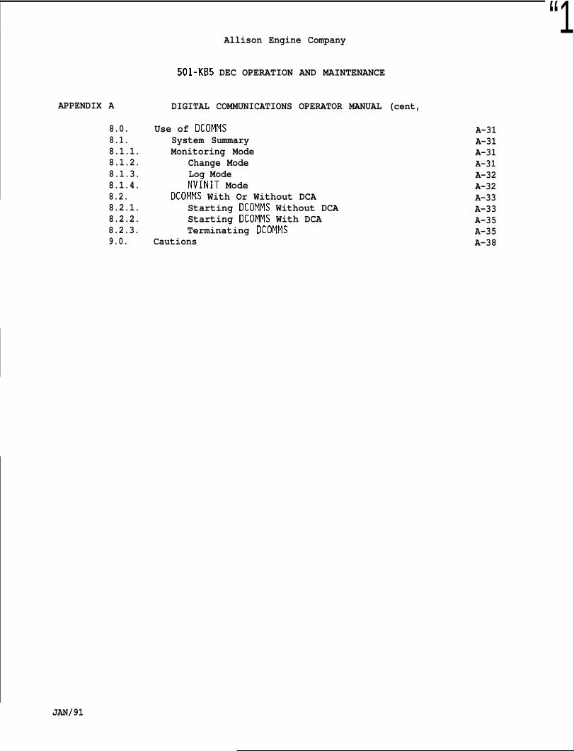
8.0.8.1.8.1.1.8.1.2.8.1.3.8.1.4.8.2.8.2.1.8.2.2.8.2.3.9.0.
Allison Engine Company
501-KB5 DEC OPERATION AND MAINTENANCE
DIGITAL COMMUNICATIONS OPERATOR MANUAL (cent,
Use of DCOMMSSystem SummaryMonitoring Mode
Change ModeLog ModeNVINIT Mode
DCOMMS With Or Without DCAStarting DCOMMS Without DCAStarting DCOMMS With DCATerminating DCOMMS
Cautions
A-31A-31A-31A-31A-32A-32A-33A-33A-35A-35A-38
JAN/91
Allison Engine Company
501-KB5 DEC OPERATION AND MAINTENANCE
EmE
1-1.1-20
1-3.1-4.1-5.1-6.2-1.2-2.
2-3.
2-4,
2-5.3-1.3-2.
3-3.
3-4.
3-5.3-6.3-7.
3-8.
1;:4-3.4-4.4-5.4-6.4-7.4-8.4-9.
4-1o.4-11.4-12.4-13.4-14.4-15.
4-16.4-17.
xxvi
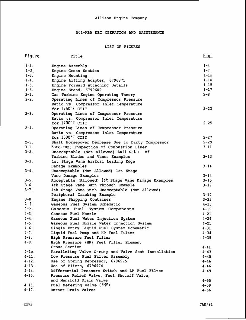
LIST OF FIGURES
Title
Engine AssemblyEngine Cross SectionEngine MountingEngine Lifting Adapter, 6796871Engine Forward Attaching DetailsEngine Stand, 6799609Gas Turbine Engine Operating TheoryOperating Lines of Compressor PressureRatio vs. Compressor Inlet Temperaturefor 1750”F CTITOperating Lines of Compressor PressureRatio vs. Compressor Inlet Temperaturefor 1700”F CTITOperating Lines of Compressor PressureRatio vs. Compressor Inlet Temperaturefor 1600”F CTITShaft Horsepower Decrease Due to Dirty CompressorBorescope Inspection of Combustion LinerUnacceptable (Not Allowed) Sulfidation ofTurbine Blades and Vanes Examples1st Stage Vane Airfoil Leading EdgeDamage ExamplesUnacceptable (Not Allowed) 1st StageVane Damage ExamplesAcceptable (Allowed) 1st Stage Vane Damage Examples4th Stage Vane Burn Through Example4th Stage Vane with Unacceptable (Not Allowed)Peripheral Cracking ExampleEngine Shipping ContainerGaseous Fuel System SchematicGaseous Fuel System ComponentsGaseous Fuel NozzleGaseous Fuel Water Injection SystemGaseous Fuel Nozzle Water Injection SystemSingle Entry Liquid Fuel System SchematicLiquid Fuel Pump and HP Fuel FilterHigh Pressure Fuel FilterHigh Pressure (HP) Fuel Filter ElementCross SectionParalleling Valve O-ring and Valve Seat InstallationLow Pressure Fuel Filter AssemblyUse of Spring Depressor, 6796975Use of Pliers, 6796974Differential Pressure Switch and LP Fuel FilterPressure Relief Valve, Fuel Shutoff Valve,and Manifold Drain ValveFuel Metering Valve (FMV)Burner Drain Valves
~
1-41-71-1o1-141-151-172-8
2-23
2-25
2-272-293-11
3-13
3-14
3-143-153-17
3-173-234-134-194-214-244-254-314-344-39
4-414-434-454-464-464-49
4-554-594-66
JAN/91
Allison Engine Company
501-KB5 DEC OPERATION AND MAINTENANCE
LIST OF FIGURES (cent)
ml!m
4-18.4-19.4-20.4-21.4-22.4-23.4-24.4-25.4-26.4-27.4-28.4-29.4-30.4-31.4-32.4-33.4-34,4-35.5-1.5-2.5-3.5-4.6-1.6-2.6-3.6-4.6-5.6-6.6-7.6-8.6-9.6-10.7-1.7-2.7-3.7-4.7-5.7-6.7-7.7-8.7-9.8-1.8-2.8-3.
8-4.8-5.8-6.
JAN/91
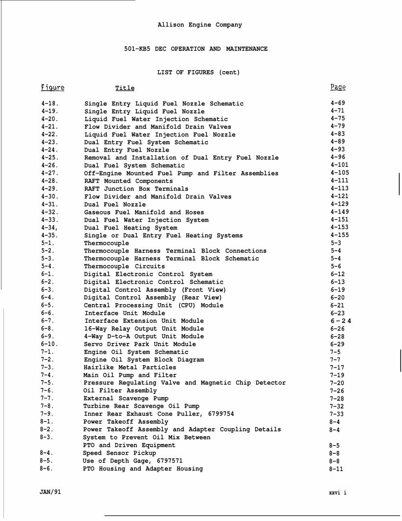
Title
Single Entry Liquid Fuel Nozzle SchematicSingle Entry Liquid Fuel NozzleLiquid Fuel Water Injection SchematicFlow Divider and Manifold Drain ValvesLiquid Fuel Water Injection Fuel NozzleDual Entry Fuel System SchematicDual Entry Fuel NozzleRemoval and Installation of Dual Entry Fuel NozzleDual Fuel System SchematicOff-Engine Mounted Fuel Pump and Filter AssembliesRAFT Mounted ComponentsRAFT Junction Box TerminalsFlow Divider and Manifold Drain ValvesDual Fuel NozzleGaseous Fuel Manifold and HosesDual Fuel Water Injection SystemDual Fuel Heating SystemSingle or Dual Entry Fuel Heating SystemsThermocoupleThermocouple Harness Terminal Block ConnectionsThermocouple Harness Terminal Block SchematicThermocouple CircuitsDigital Electronic Control SystemDigital Electronic Control SchematicDigital Control Assembly (Front View)Digital Control Assembly (Rear View)Central Processing Unit (CPU) ModuleInterface Unit ModuleInterface Extension Unit Module16-Way Relay Output Unit Module4-Way D-to-A Output Unit ModuleServo Driver Park Unit ModuleEngine Oil System SchematicEngine Oil System Block DiagramHairlike Metal ParticlesMain Oil Pump and FilterPressure Regulating Valve and Magnetic Chip DetectorOil Filter AssemblyExternal Scavenge PumpTurbine Rear Scavenge Oil PumpInner Rear Exhaust Cone Puller, 6799754Power Takeoff AssemblyPower Takeoff Assembly and Adapter Coupling DetailsSystem to Prevent Oil Mix BetweenPTO and Driven EquipmentSpeed Sensor PickupUse of Depth Gage, 6797571PTO Housing and Adapter Housing
&
4-694-714-754-794-834-894-934-964-1014-1054-1114-1134-1214-1294-1494-1514-1534-1555-35-45-45-66-126-136-196-206-216-236 - 2 46-266-286-297-57-77-177-197-207-267-287-327-338-48-4
8-58-88-88-11
xxvi i
Allison Engine Company
501-KB5 DEC OPERATION AND MAINTENANCE
LIST OF FIGURES (cent)
EmrE
8-7.8-8.8-9.
8-10.8-11.8-12.8-13.8-14.9-1.9-2.9-3.9-4.1o-1.10-2.
10-3.
10-4.10-5.10-6.10-7.11-1.11-2.11-3.11-4.11-5.12-1.12-2.12-3.12-4.12-5.
13-1.13-2.13-3.13-4.13-5.13-6.13-7.
13-8.13-9.
13-10.13-11.13-12.
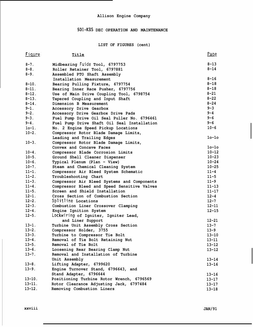
xxviii
Title
Midbearing Fuide Tool, 6797753Roller Retainer Tool, 6797881Assembled PTO Shaft AssemblyInstallation MeasurementBearing Pulling Fixture, 6797754Bearing Inner Race Pusher, 6797756Use of Main Drive Coupling Tool, 6798754Tapered Coupling and Input ShaftDimension B MeasurementAccessory Drive GearboxAccessory Drive Gearbox Drive PadsFuel Pump Drive Oil Seal Puller No. 6796461Fuel Pump Drive Shaft Oil Seal InstallationNo. 2 Engine Speed Pickup LocationsCompressor Rotor Blade Damage Limits,Leading and Trailing EdgesCompressor Rotor Blade Damage Limits,Convex and Concave FacesCompressor Blade Corrosion LimitsGround Shell Cleaner DispenserTypical Plenum (Plan - View)Steam and Chemical Cleaning SystemCompressor Air Bleed System SchematicTroubleshooting ChartCompressor Air Bleed Systems and ComponentsCompressor Bleed and Speed Sensitive ValvesScreen and Shield InstallationCross Section of Combustion SectionSplitline LocationsCombustion Liner Crossover ClampingEngine Ignition SystemLockwiring of Igniter, Igniter Lead,
and Liner SupportTurbine Unit Assembly Cross SectionCompressor Holder, 3755Turbine to Compressor Tie BoltRemoval of Tie Bolt Retaining NutRemoval of Tie BoltLoosening Rear Bearing Clamp NutRemoval and Installation of TurbineUnit AssemblyLifting Adapter, 6799620Engine Turnover Stand, 6796643, andStand Adapter, 6796644Positioning Turbine Rotor Wrench, 6796569Rotor Clearance Adjusting Jack, 6797484Removing Combustion Liners
&
8-138-14
8-168-188-188-218-228-249-39-49-69-610-6
1o-1o
1o-1o10-1210-2310-2410-2511-411-511-911-1311-1712-412-712-1112-15
12-2113-713-913-1013-1113-1213-12
13-1413-16
13-1613-1713-1713-18
JAN/91
Allison Engine Company
501-KB5 DEC OPERATION AND MAINTENANCE
LIST OF FIGURES (cent)
EWE
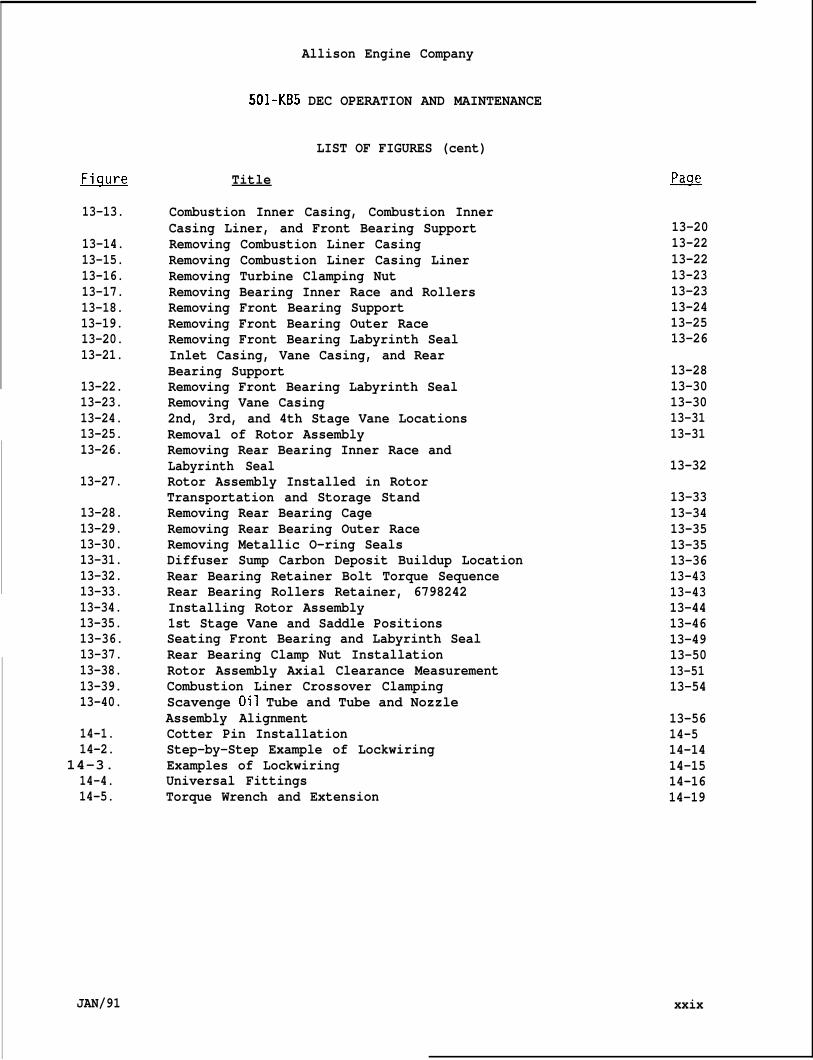
13-13.
13-14.13-15.13-16.13-17.13-18.13-19.13-20.13-21.
13-22.13-23.13-24.13-25.13-26.
13-27.
13-28.13-29.13-30.13-31.13-32.13-33.13-34.13-35.13-36.13-37.13-38.13-39.13-40.
14-1.14-2.
14-3.14-4.14-5.
JAN/91
Title
Combustion Inner Casing, Combustion InnerCasing Liner, and Front Bearing SupportRemoving Combustion Liner CasingRemoving Combustion Liner Casing LinerRemoving Turbine Clamping NutRemoving Bearing Inner Race and RollersRemoving Front Bearing SupportRemoving Front Bearing Outer RaceRemoving Front Bearing Labyrinth SealInlet Casing, Vane Casing, and RearBearing SupportRemoving Front Bearing Labyrinth SealRemoving Vane Casing2nd, 3rd, and 4th Stage Vane LocationsRemoval of Rotor AssemblyRemoving Rear Bearing Inner Race andLabyrinth SealRotor Assembly Installed in RotorTransportation and Storage StandRemoving Rear Bearing CageRemoving Rear Bearing Outer RaceRemoving Metallic O-ring SealsDiffuser Sump Carbon Deposit Buildup LocationRear Bearing Retainer Bolt Torque SequenceRear Bearing Rollers Retainer, 6798242Installing Rotor Assembly1st Stage Vane and Saddle PositionsSeating Front Bearing and Labyrinth SealRear Bearing Clamp Nut InstallationRotor Assembly Axial Clearance MeasurementCombustion Liner Crossover ClampingScavenge Oil Tube and Tube and NozzleAssembly AlignmentCotter Pin InstallationStep-by-Step Example of LockwiringExamples of LockwiringUniversal FittingsTorque Wrench and Extension
13-2013-2213-2213-2313-2313-2413-2513-26
13-2813-3013-3013-3113-31
13-32
13-3313-3413-3513-3513-3613-4313-4313-4413-4613-4913-5013-5113-54
13-5614-514-1414-1514-1614-19
xxix
Allison Engine Company
501-KB5 DEC OPERATION AND MAINTENANCE
LIST OF TABLES
Table
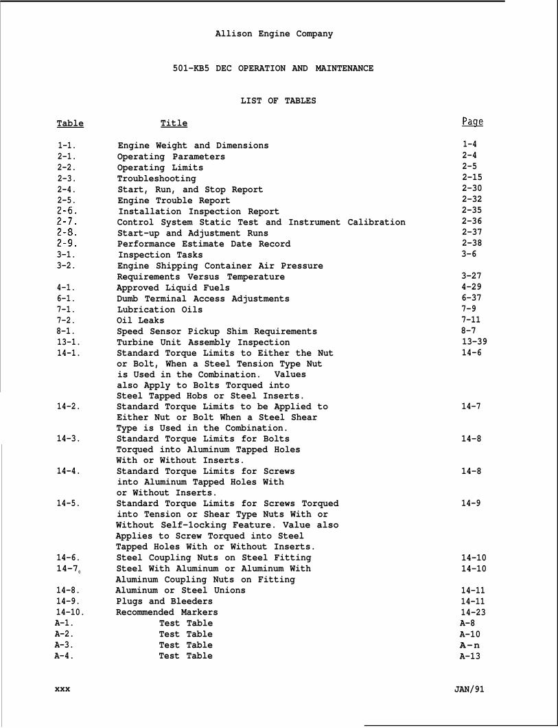
1-1.2-1.2-2.2-3.2-4.2-5.
;$:
;:::3-1.3-2.
4-1.6-1.7-1.7-2.8-1.13-1.14-1.
14-2.
14-3.
14-4.
14-5.
14-6.14-70
14-8.14-9.14-10.A-1.A-2.A-3.A-4.
xxx
Title
Engine Weight and DimensionsOperating ParametersOperating LimitsTroubleshootingStart, Run, and Stop ReportEngine Trouble ReportInstallation Inspection ReportControl System Static Test and Instrument CalibrationStart-up and Adjustment RunsPerformance Estimate Date RecordInspection TasksEngine Shipping Container Air PressureRequirements Versus TemperatureApproved Liquid FuelsDumb Terminal Access AdjustmentsLubrication OilsOil LeaksSpeed Sensor Pickup Shim RequirementsTurbine Unit Assembly InspectionStandard Torque Limits to Either the Nutor Bolt, When a Steel Tension Type Nutis Used in the Combination. Valuesalso Apply to Bolts Torqued intoSteel Tapped Hobs or Steel Inserts.Standard Torque Limits to be Applied toEither Nut or Bolt When a Steel ShearType is Used in the Combination.Standard Torque Limits for BoltsTorqued into Aluminum Tapped HolesWith or Without Inserts.Standard Torque Limits for Screwsinto Aluminum Tapped Holes Withor Without Inserts.Standard Torque Limits for Screws Torquedinto Tension or Shear Type Nuts With orWithout Self-1ocking Feature. Value alsoApplies to Screw Torqued into SteelTapped Holes With or Without Inserts.Steel Coupling Nuts on Steel FittingSteel With Aluminum or Aluminum WithAluminum Coupling Nuts on FittingAluminum or Steel UnionsPlugs and BleedersRecommended Markers
Test TableTest TableTest TableTest Table
~
1-42-42-52-152-302-322-352-362-372-383-6
3-274-296-377-97-118-713-3914-6
14-7
14-8
14-8
14-9
14-1014-10
14-1114-1114-23A-8A-10A-nA-13
JAN/91
Table
A-5.A-6.A-7.A-8.A-9.A-10.A-n.A-12.A-13.A-14.A-15.A-16.A-17.A-18.A-19.A-20.
Allison Engine Company
501-KB5 DEC OPERATION AND MAINTENANCE
LIST OF TABLES (cent)
Title
Test TableTest TableTest TableTest TableTest TableTest TableTest TableTest TableTest TableTest TableTest TableTest TableTest TableTest TableTest TableTest Table
A-14A-16A-20A-21A-22A-23A-24A-25A-26A-29A-33A-34A-34A-36A-37A-37
~ JAN/91 xxxi
Paraqrar)h
1-1
1-3
1-5
1-8
1-10
1-12
1-14
1-16
1-18
1-20
1-22
1-24
1-26
1-27
1-29
1-30
1-31
1-32
1-33
1-34
1-35
JAN/91
I
Allison Engine Company
501-KB5 DEC OPERATION AND MAINTENANCE
, SECTION 1
ENGINE DESCRIPTION
TABLE OF CONTENTS
Descri~tion
General Definitions
Weights and Dimensions
Engine Description
Compressor Section
Accessory Drive Gearbox
Combustion Section
Turbine Unit Assembly
Turbine Outlet Temperature (TOT)
Lubrication (Lube) System
Ignition System
Fuel and Control System
Power Takeoff Assembly
Engine Mounting
Cool ing
Engine Configuration Options
Operating and Maintenance Precautions
Lifting and Handling Information
Removal
Installing Engine in Engine Stand
Removal Engine From Engine Stand
Installation
Paqe No.
1-3
1-3
1-4
1-5
1-5
1-5
1-5
1-6
1-6
1-6
1-6
1-6
1-9
1-11
1-11
1-11
1-12
1-12
1-16
1-16
1-18
1-1
Fiqure No.
1-1
1-2
1-3
1-4
1-5
1-6
Allison Engine Company
501-KB5 DEC OPERATION AND MAINTENANCE
I~DEX TO FIGURES
Engine Assembly
Engine Cross Section
Engine Mounting
Engine Lifting Adapter, 6796871
Engine Forward Attaching Details
Engine Stand, 6799609
INDEX TO TABLES
Table No. Title
1-1 Engine Weight and Dimensions
Paqe No.
1-4
1-7
1-10
1-14
1-15
1-17
Paqe No.
1-4
1-2 .
Allison Engine Company
501-KB5 DEC OPERATION AND MAINTENANCE
SECTION 1
ENGINE DESCRIPTION
1-1. GENERAL DEFINITIONS.
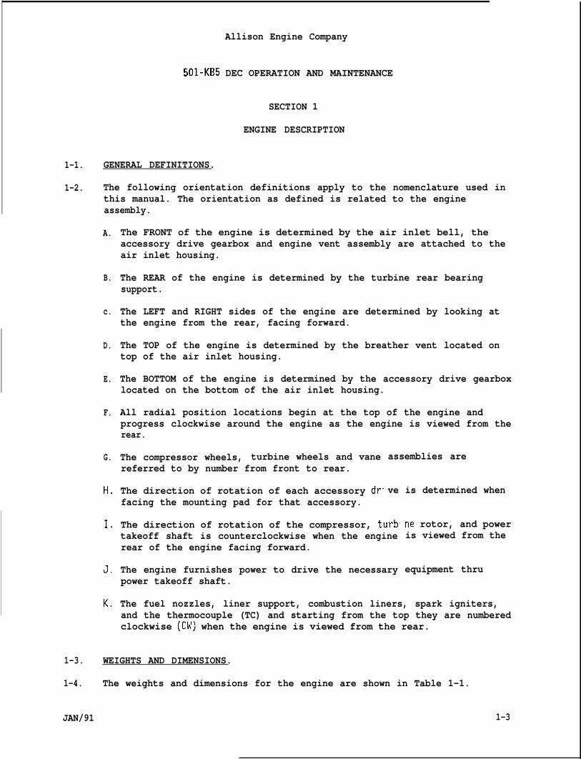
1-2. The following orientation definitions apply to the nomenclature used inthis manual. The orientation as defined is related to the engineassembly.
A.
B.
c.
D.
E.
F.
G.
H,
1.
J<
K,
The FRONT of the engine is determined by the air inlet bell, theaccessory drive gearbox and engine vent assembly are attached to theair inlet housing.
The REAR of the engine is determined by the turbine rear bearingsupport.
The LEFT and RIGHT sides of the engine are determined by looking atthe engine from the rear, facing forward.
The TOP of the engine is determined by the breather vent located ontop of the air inlet housing.
The BOTTOM of the engine is determined by the accessory drive gearboxlocated on the bottom of the air inlet housing.
All radial position locations begin at the top of the engine andprogress clockwise around the engine as the engine is viewed from therear.
The compressor wheels, turbine wheels and vanereferred to by number from front to rear.
The direction of rotation of each accessory drfacing the mounting pad for that accessory.
assemblies are
ve is determined when
The direction of rotation of the compressor, turbtakeoff shaft is counterclockwise when the enginerear of the engine facing forward.
The engine furnishes power to drive the necessarypower takeoff shaft.
ne rotor, and poweris viewed from the
equipment thru
The fuel nozzles, liner support, combustion liners, spark igniters,and the thermocouple (TC) and starting from the top they are numberedclockwise (CW) when the engine is viewed from the rear.
1-3. WEIGHTS AND DIMENSIONS.
1-4. The weights and dimensions for the engine are shown in Table 1-1.
JAN/91 1-3

Allison Engine Company
501-KB5 DEC OPERATION AND MAINTENANLk
1-5. ENGINE DESCRIPTION.
1-6. The gas turbine engine with a digital electrical control (DEC) systemis divided into a compressor section, a combustion section, a“ turbineunit assembly (coupled to the compressor), and an accessory drivegearbox (Ref. Figures 1-1 and 1-2).
Table 1-1. Engine Weight and Dimensions.
Weight 1270 lb (577 kg)
Length, with Power Takeoff Shaft 123.7 in. (3141.9 mm)
Width 22.24 in. (564.9 mm)
Height 29.85 in. (758.2 mm)
Mechanical Limit (Max.) 37,700 lb in. (4259.5 Nom)
Normal Operating Speed 13,800 to 14,600 rpm II
COMPRESSORANDINLET
60MBusTi0NANDTURBINESECTION
QHA018XD
JAN/91
ACCESSORYDRIVE
GEARBOX
Figure 1-1. Engine Assembly,
.1-4
Allison Engine Company
501-KB5 DEC OPERATION AND MAINTENANCE
1-8. COMPRESSOR SECTION.
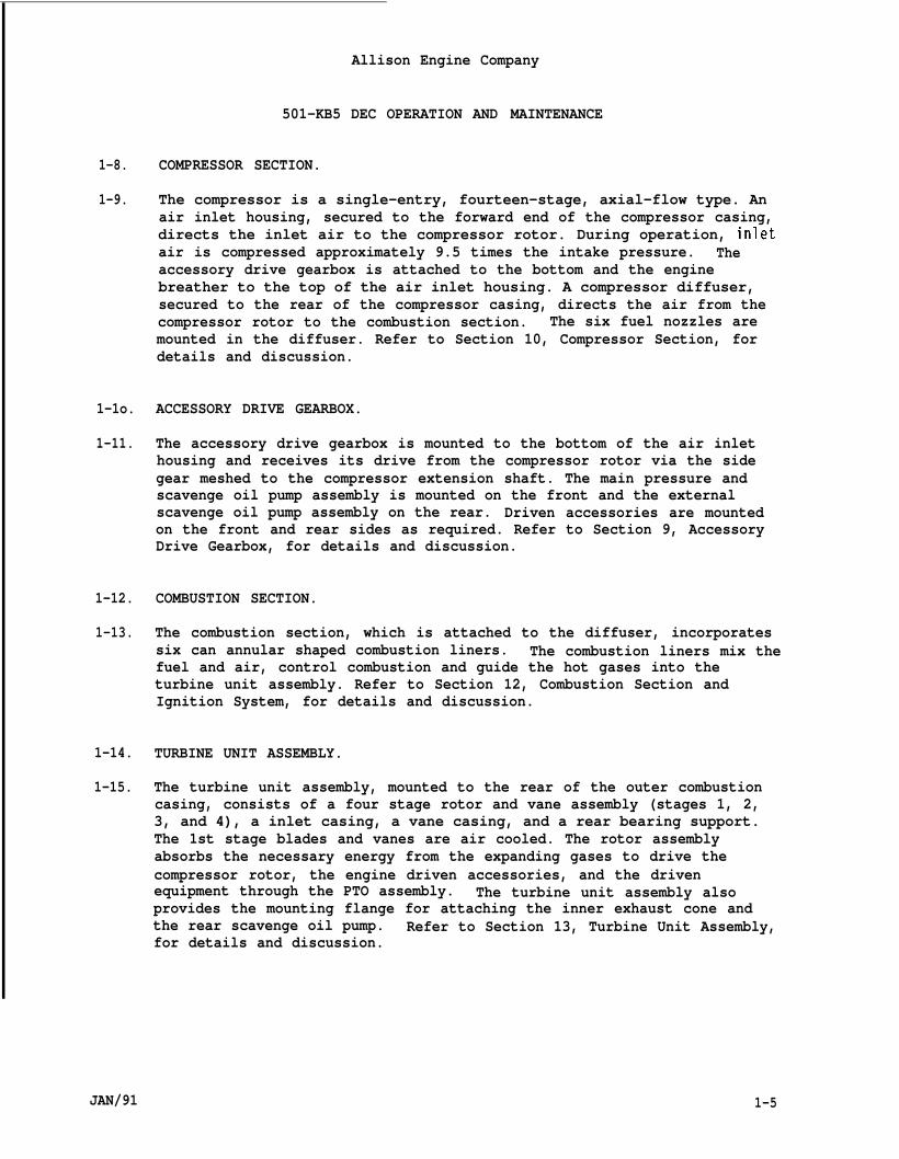
1-9. The compressor is a single-entry, fourteen-stage, axial-flow type. Anair inlet housing, secured to the forward end of the compressor casing,directs the inlet air to the compressor rotor. During operation, inletair is compressed approximately 9.5 times the intake pressure. Theaccessory drive gearbox is attached to the bottom and the enginebreather to the top of the air inlet housing. A compressor diffuser,secured to the rear of the compressor casing, directs the air from thecompressor rotor to the combustion section. The six fuel nozzles aremounted in the diffuser. Refer to Section 10, Compressor Section, fordetails and discussion.
1-1o. ACCESSORY DRIVE GEARBOX.
1-11. The accessory drive gearbox is mounted to the bottom of the air inlethousing and receives its drive from the compressor rotor via the sidegear meshed to the compressor extension shaft. The main pressure andscavenge oil pump assembly is mounted on the front and the externalscavenge oil pump assembly on the rear. Driven accessories are mountedon the front and rear sides as required. Refer to Section 9, AccessoryDrive Gearbox, for details and discussion.
1-12. COMBUSTION SECTION.
1-13. The combustion section, which is attached to the diffuser, incorporatessix can annular shaped combustion liners. The combustion liners mix thefuel and air, control combustion and guide the hot gases into theturbine unit assembly. Refer to Section 12, Combustion Section andIgnition System, for details and discussion.
1-14. TURBINE UNIT ASSEMBLY.
1-15. The turbine unit assembly, mounted to the rear of the outer combustioncasing, consists of a four stage rotor and vane assembly (stages 1, 2,3, and 4), a inlet casing, a vane casing, and a rear bearing support.The 1st stage blades and vanes are air cooled. The rotor assemblyabsorbs the necessary energy from the expanding gases to drive thecompressor rotor, the engine driven accessories, and the drivenequipment through the PTO assembly. The turbine unit assembly alsoprovides the mounting flange for attaching the inner exhaust cone andthe rear scavenge oil pump. Refer to Section 13, Turbine Unit Assembly,for details and discussion.
JAN/91 1-5
Allison Engine Company
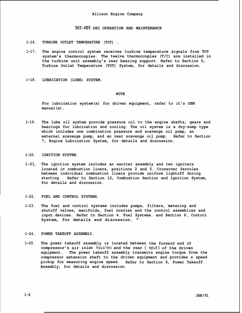
1-16.
1-17.
1-18.
1-19.
1-20.
1-210
1-22.
1-23.
1-24.
1-25.
1-6
501-KB5 DEC OPERATION AND MAINTENANCE
TURBINE OUTLET TEMPERATURE (TOT) .
The engine control system receives turbine temperature signals from TOTsystem’s thermocouples. The twelve thermocouples (T/C) are installed inthe turbine unit assembly’s rear bearing support. Refer to Section 5,Turbine Outlet Temperature (TOT) System, for details and discussion.
LUBRICATION (LUBE) SYSTEM.
NOTE
For lubrication system(s) for driven equipment, refer to it’s OEMmanual(s).
The lube oil system provide pressure oil to the engine shafts, gears andbearings for lubrication and cooling. The oil system is a dry-sump typewhich includes one combination pressure and scavenge oil pump, anexternal scavenge pump, and an rear scavenge oil pump. Refer to Section7, Engine Lubrication System, for details and discussion.
IGNITION SYSTEM.
The ignition system includes an exciter assembly and two igniterslocated in combustion liners, positions 2 and 5. Crossover ferrulesbetween individual combustion liners provide uniform lightoff duringstarting. Refer to Section 12, Combustion Section and Ignition System,for details and discussion.
FUEL AND CONTROL SYSTEMS.
The fuel and control systems includes pumps, filters, metering andshutoff valves, manifolds, fuel nozzles and the control assemblies andinput devices. Refer to Section 4. Fuel Systems. and Section 6. Control,System, for details and discussion. “
POWER TAKEOFF ASSEMBLY.
The power takeoff assembly is located betweencompressor’s air inlet housina and the rear (
the forward end ofnput) of the driven.
equipment. The power takeoff assembly transmits engine torque from thecompressor extension shaft to the driven equipment and provides a speedpickup for measuring engine speed. Refer to Section 8, Power TakeoffAssembly, for details and discussion.
JAN/91
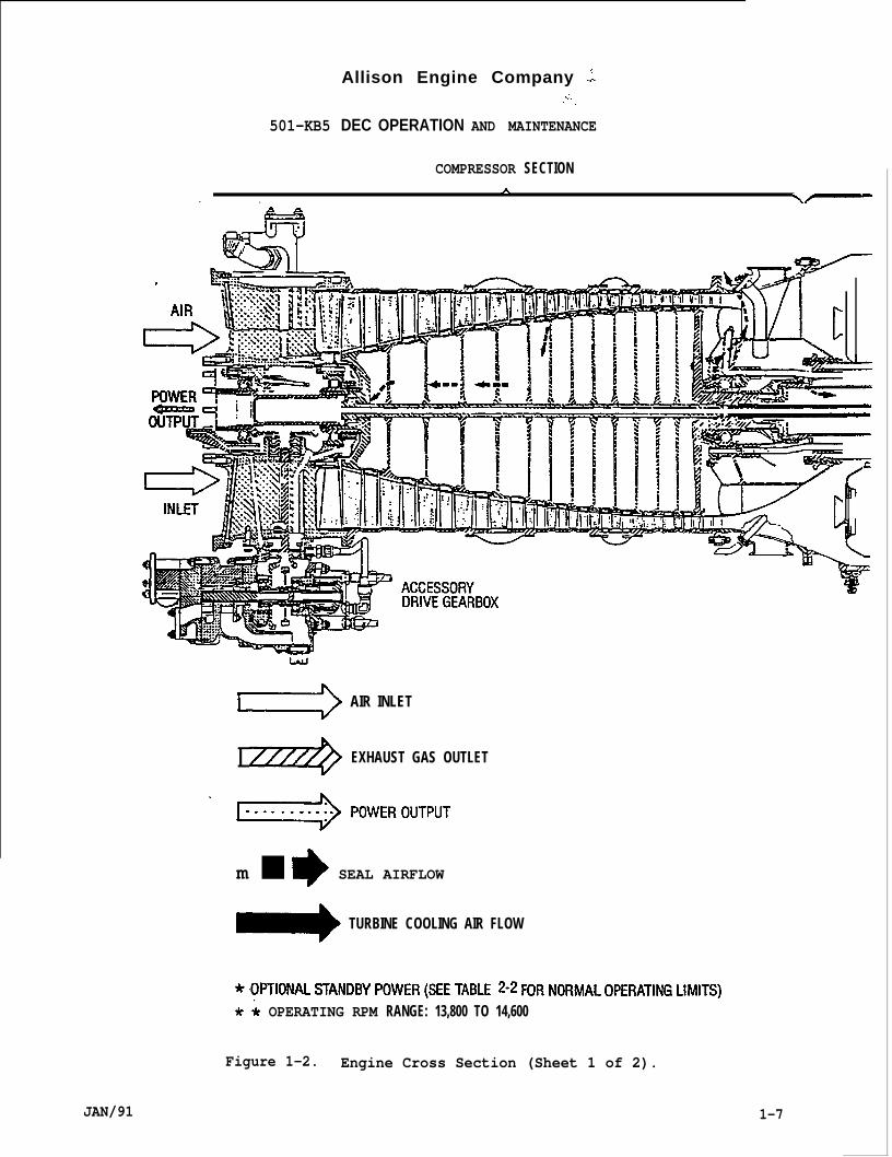
Allison Engine Company .;.;.,.
501-KB5 DEC OPERATION AND MAINTENANCE
COMPRESSOR SECTIONA
. . \~
&.,{/ , \\
JAN/91
=2 AIR INLET
I ////+ EXHAUST GAS OUTLET
“ -pOwEROuTpuTm ■ * SEAL AIRFLOW
TURBINE COOLING AIR FLOW
* OPTIONAL STANDBY ‘()”ER (SEE TABLE 2.2 FOR NORMAL OPERATING LIMITS)
* & OPERATING RPM RANGE: 13,800 TO 14,600
Figure 1-2. Engine Cross Section (Sheet 1 of 2).
1-7
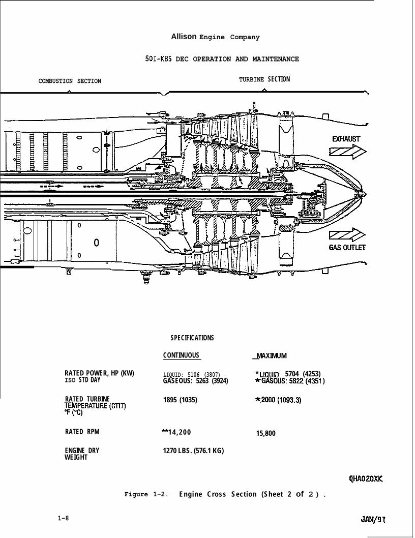
Allison Engine Company
501-KB5 DEC OPERATION AND MAINTENANCE
COMBUSTION SECTION TURBINE SECTION
A Y/A \
u
:
u-‘00
0
0
d
SPECIFICATIONS
CONTINUOUS
RATED POWER, HP (KW) LIQUID: 5106 (3807)ISO STD DAY GASEOUS: 5263 (3924)
RATED TURBINE 1895 (1035)lHII~fRATURE (CTIT)
RATED RPM * * 1 4 , 2 0 0
ENGINE DRYWEIGHT
1270 LBS. (576.1 KG)
Figure 1-2.
MAXIMUM—
* LIQUID: 5704 (4253)*GASOUS:5822(4351 )
*.2(JO()(~()93.3)
15,800
QHA020XK
Engine Cross Section (Sheet 2 of 2 ) .
1-8 JAN/91
Allison Engine Company
501-KB5 DEC OPERATION AND MAINTENANCE
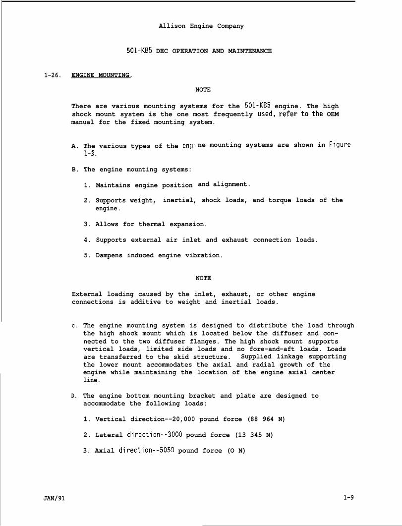
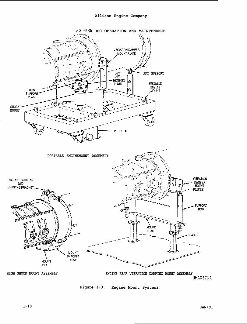
1-26. ENGINE MOUNTING.
NOTE
There are various mounting systems for the 501-KB5 engine. The highshock mount system is the one most frequently used, refer to the OEMmanual for the fixed mounting system.
A. The various types of the eng” ne mounting systems are shown in Fgure1-3.
B. The engine mounting systems:
1. Maintains engine position and alignment.
2. Supports weight, inertial, shock loads, and torque loads of theengine.
3. Allows for thermal expansion.
4. Supports external air inlet and exhaust connection loads.
5. Dampens induced engine vibration.
NOTE
External loading caused by the inlet, exhaust, or other engineconnections is additive to weight and inertial loads.
c.
D.
The engine mounting system is designed to distribute the load throughthe high shock mount which is located below the diffuser and con-nected to the two diffuser flanges. The high shock mount supportsvertical loads, limited side loads and no fore-and-aft loads. Loadsare transferred to the skid structure. Supplied linkage supportingthe lower mount accommodates the axial and radial growth of theengine while maintaining the location of the engine axial centerline.
The engine bottom mounting bracket and plate are designed toaccommodate the following loads:
1. Vertical direction--20,000 pound force (88 964 N)
2. Lateral direction--3OOO pound force (13 345 N)
3. Axial direction--5O5O pound force (O N)
JAN/91 1-9
Allison Engine Company
501-KB5 DEC OPERATION AND MAINTENANCE\: ,,‘Hi’\, “!
SHOCKMOUNT
f ([:..
J-q,, _/“:Wc,,<jq -<=
~ AFT SUPPORT
A{ri
MOUNT ~PLATE PORTABLE
-=4!0ENGINE
,MOUNT
PORTABLE ENGINEMOUNT ASSEMBLY
ENGINE HANDLINGAND
SHIPPINGBRACKET~
*@
Ih(ik; )1/1 r DAMPER/w MOUNT= PLATE
- ---—
HIGH SHOCK MOUNT ASSEMBLY ENGINE REAR VIBRATION DAMPING MOUNT ASSEMBLYQHA017XA
Figure 1-3. Engine Mount Systems.
1-10 JAN/91

1-27.
1-28.
1-29.
1-30.
COOLING.
The engine requires external cooling. OEM provisions for cooling theengine room or engine enclosure and control components are necessary andmust be maintained. It is important that the cooling air have a uniformflow over the engine hot section to avoid any case warpage. Thecombustion section and parts of the turbine are air cooled by internalsecondary air (air not required for combustion).
ENGINE CONFIGURATION OPTIONS.
NOTE
As a result of engine improvements or the incorporation of variousoptions which owners/operators may select or choose to make systemmodifications which affect the engine, this manual may not reflect thesespecific engines in service.
OPERATING AND MAINTENANCE PRECAUTIONS.
Allison Engine Company
501-KB5 DEC OPERATION AND MAINTENANCE
.
NOTE
Refer to OEM’s Manual for a complete Operating and MaintenancePrecaution. The following are the Operating and Maintenance Precautionsrequired by Allison Gas Turbine.
A. Establish a daily thorough installation and walk around visualinspection (Refer to Section 3).
B. Maintain clean gaseous and/or liquid fuel filters. Check thepressure drops of the fuel filters regularly. A dirty fuel filtersystem with resulting high pressure losses can reduce the power ofthe engine (Refer to Sections 2 and/or 3).
NOTE
● Allison Gas Turbine highly recommends the engine oil system be placedin the sample oil analysis program (SOAP).
. If the periodic sample analysis indicates acid and viscosity numbershave increased significantly, more frequent oil sampling should beinitiated. Recommend three months or sooner.
JAN/91 1-11
c.
D.
E.
F.
G.
H.
I.
J.
IAllison Engine Company
501-KB5 DEC OPERATION AND MAINTENANCE
Take an oil sample every six months or as recommended by the oilmanufacturer. Inspect the oil sample for contamination and have thesample analyzed to determine total acid number (TAN) and viscosity,(refer to Industrial Engine Bulletin 8-GT-84). Additionally, on anannual basis, or as recommended by the oil manufacturer, the oilsample should be analyzed for the quality and integrity of the oiladditive packages used in the base lubricant.
Before the engine is started, accomplish prestart check. The use ofcheck lists,such as thosestrongly encouraged by Al’
Prior to starting the engunnecessary personnel.
included in the Maintenance Practices isison Gas Turbine.
ne, clear the engine room (area) of all
Monitor starting and running operations with correctly calibratedinstrumentation and with well trained personnel.
Do not rely wholly on automatic devices to handle an emergency. Bothautomation and human manual control should be available to accomplishan operational task.
Do not stabilize at speeds below engine idle, at least 13,000 rpm.The control system is designed to prevent such operation.
When engine running is simulated, regardless of method and kind,check for any ancillary control circuitry which may be activated(fuel, lube, air, high voltage systems) but should not be operatedduring the test. Conversely, check that those devices and systems,which are required for a proper test, installation well being andhuman safety, are activated.
When increasing power, power should be increased in a steadv.conservative m;nner to the required level. Increasing engi;e turbinetemperature more rapidly and to a higher level than necessary willshorten the turbine life.
1-31. LIFTING AND HANDLING INFORMATION.
1-32. REMOVAL.
A. Make sure all electrical,OFF until installation is
CAP ALL HOSES, HARNESS ENDS,REQUIRED, RECORD OR IDENTIFYINSTALLATION.
fuel, and oil systems are OFF and remaincompleted.
CAUTION
AND OPENINGS TO PREVENT CONTAMINATION. IFALL HOSES, HARNESS ENDS, AND OPENINGS FOR
1-12 JAN/91
Allison Engine Company
501 -KB5 DEC OPERATION AND MAINTENANCE
NOTE
. If required, save fluids (fuel, oil , etc.) for inspection to aid introubleshooting.
● Have a container available to catch fluids.
I.
JAN/91
B.
c.
D.
E.
F.
G.
Remove all hose and engine electrical harness connections. Ifrequired, record or identify hose and harness connections. Plug orcap all openings, hoses, and harness connections (Refer to OEMmanual).
Remove the engine exhaust system (augmenter) from engine exhaustdiffuser (Refer to OEM manual).
Remove clamp and move air inlet bell forward to inside of air inletplenum (Refer to OEM manual.
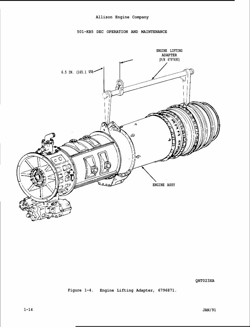
Install engine lifting adapter, 6796871, to lifting brackets at thediffuser and turbine rear bearing support lift brackets spl itlines(Ref. Figure 1-4).
Attach a hoist to engine lifting adapter, 6796871, and remove engineweight from the engine mount(s) from engine support.
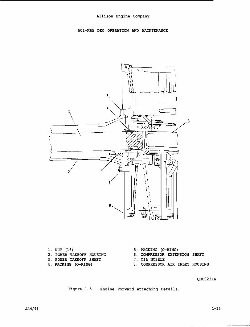
Remove nuts (1, Figure 1-5) at the power takeoff housinq (2) andcompressor air inlet housing (8) spl itline.
-..
NOTE
Due to the various mounting brackets hookup to the fixed engine support,refer to the OEM manual for removal and installation.
H. Remove mounting bolts and nuts from mounting bracket(s) and fixedengine support (Refer to OEM manual).
CAUTION
MAINTAIN ENGINE ALIGNMENT HORIZONTALLY AND VERTICALLY DURING SEPARATIONOR ------ . . . .DAMAGE MAY OCCUR.
Slowly separate engine’s compressor extension shaft (6) from thepower takeoff housing (2) and power takeoff shaft (3) by movingengine aft at least 3.5 inches (88.9 mm). When engine has cleared,hoist engine away from fixed engine support. Remove O-rings (4 and5) and discard.
1-13
Allison Engine Company
501-KB5 DEC OPERATION AND MAINTENANCE
ENGINE LIFTINGADAPTER
/ (P/N 6797690)
6.5 IN. (165.1 MM)-
ENGINE ASSY
QHT023XA
Figure 1-4. Engine Lifting Adapter, 6796871.
1-14 JAN/91
3\
Allison Engine Company
501-KB5 DEC OPERATION AND MAINTENANCE
\./. ,— /,,
/6
(uL——_J
1. NUT (16)2. POWER TAKEOFF HOUSING3. POWER TAKEOFF SHAFT4. PACKING (O-RING)
w J
5. PACKING (O-RING)6. COMPRESSOR EXTENSION SHAFT7. OIL NOZZLE8. COMPRESSOR AIR INLET HOUSING
QHC023XA
Figure 1-5. Engine Forward Attaching Details.
JAN/91 1-15
Allison Engine Company
501-KB5 DEC OPERATION AND MAINTkNANLt
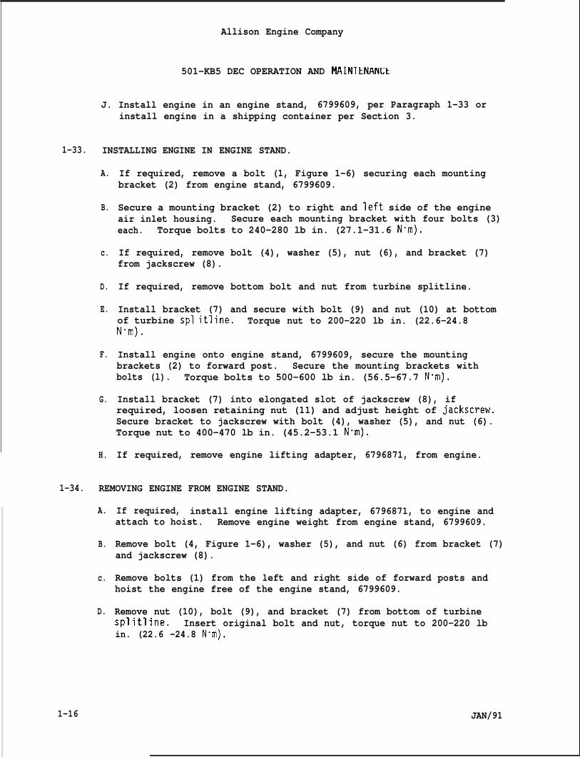
J. Install engine in an engine stand, 6799609, per Paragraph 1-33 orinstall engine in a shipping container per Section 3.
1-33. INSTALLING ENGINE IN ENGINE STAND.
A.
B.
c.
D.
E.
F.
G.
H.
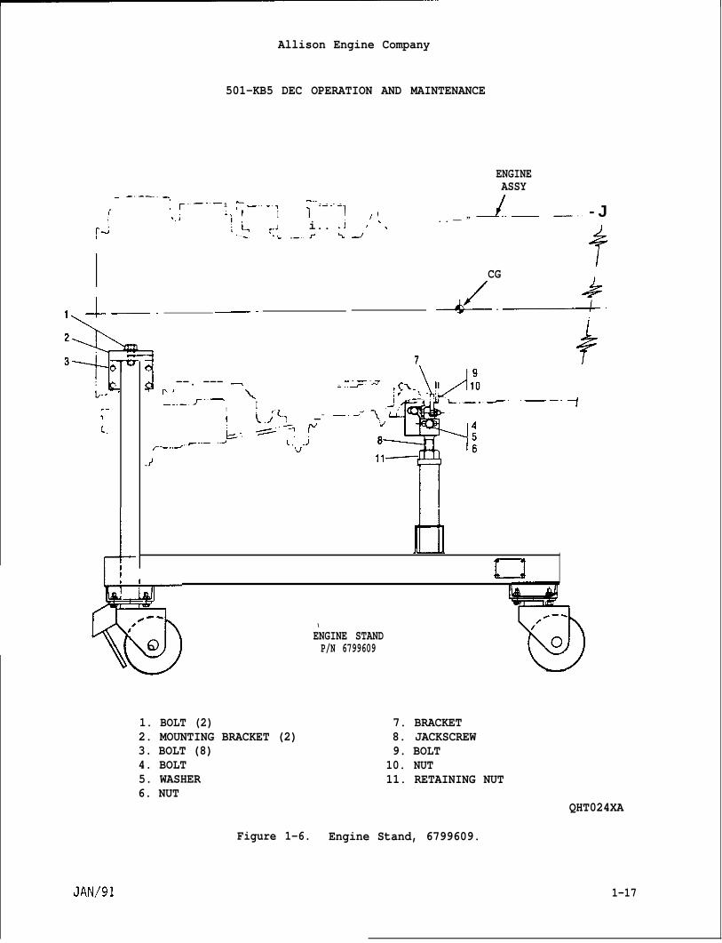
If required, remove a bolt (1, Figure 1-6) securing each mountingbracket (2) from engine stand, 6799609.
Secure a mounting bracket (2) to right and left side of the engineair inlet housing. Secure each mounting bracket with four bolts (3)each. Torque bolts to 240-280 lb in. (27.1-31.6 Nom).
If required, remove bolt (4), washer (5), nut (6), and bracket (7)from jackscrew (8).
If required, remove bottom bolt and nut from turbine splitline.
Install bracket (7) and secure with bolt (9) and nut (10) at bottomof turbine spl itline. Torque nut to 200-220 lb in. (22.6-24.8Nom).
Install engine onto engine stand, 6799609, secure the mountingbrackets (2) to forward post. Secure the mounting brackets withbolts (l). Torque bolts to 500-600 lb in. (56.5-67.7 N-m).
Install bracket (7) into elongated slot of jackscrew (8), ifrequired, loosen retaining nut (11) and adjust height of jackscrew.Secure bracket to jackscrew with bolt (4), washer (5), and nut (6).Torque nut to 400-470 lb in. (45.2-53.1 N“m).
If required, remove engine lifting adapter, 6796871, from engine.
1-34. REMOVING ENGINE FROM ENGINE STAND.
A.
B.
c.
D.
1-16
If required, install engine lifting adapter, 6796871, to engine andattach to hoist. Remove engine weight from engine stand, 6799609.
Remove bolt (4, Figure 1-6), washer (5), and nut (6) from bracket (7)and jackscrew (8).
Remove bolts (1) from the left and right side of forward posts andhoist the engine free of the engine stand, 6799609.
Remove nut (10), bolt (9), and bracket (7) from bottom of turbinesplitline. Insert original bolt and nut, torque nut to 200-220 lbin. (22.6 -24.8 N”m).
JAN/91
501-KB5 DEC OPERATION AND MAINTENANCE
ENGINEASSY
Allison Engine Company
~.J i.. .j-L. .—.. J” t
. ------1 -..~.. —..— 1 :_.. _., - - - -
> ,,
i:.1~.; I 111, ,/ !\,,
— . — -‘\+
L-.’
f-.
!5cJ-
4 --. —-- -P]
--. _.. J--’—\
! II {..;”z; --
~., +””-= !“~_-.=..F-.- ..4 l.V. J
. ..>—
~<—.
#-II
J..—. . — ”
CG
/&-—
—.. - J
-----4-
,_. .— —. -1
6la
I
,--\0
1 ENGINE STANDo P/N 6799609
1. BOLT (2)2. MOUNTING BRACKET (2)3. BOLT (8)4. BOLT5. WASHER6. NUT
7. BRACKET8. JACKSCREW9. BOLT
10. NUT11. RETAINING NUT
QHT024XA
Figure 1-6. Engine Stand, 6799609.
1-17
Allison Engine Company
501-KB5 DEC OPERATION AND MAINTENANCE
E.
F.
G.
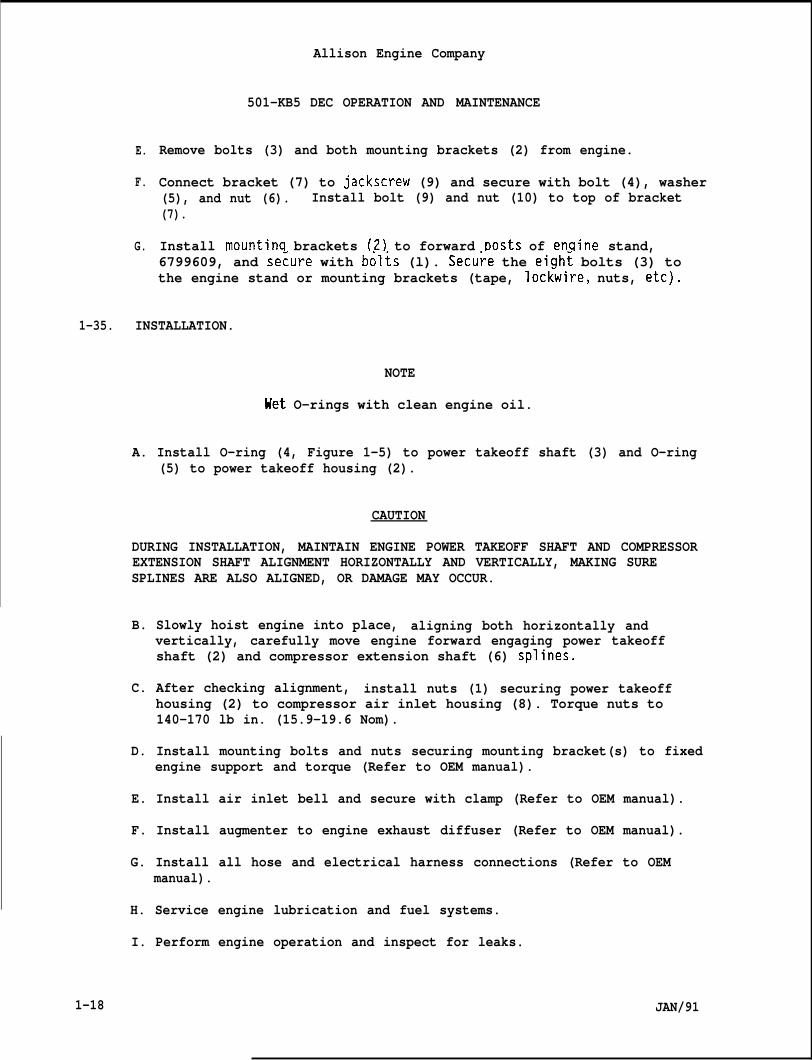
Remove bolts (3) and both mounting brackets (2) from engine.
Connect bracket (7) to jackscrew (9) and secure with bolt (4), washer(5), and nut (6). Install bolt (9) and nut (10) to top of bracket(7).
Install mountina brackets (2) to forward Dosts of en~ine stand,6799609, and se~ure with bdlts (l). Secu~e the eigh~ bolts (3) tothe engine stand or mounting brackets (tape, lockwire, nuts, etc).
1-35. INSTALLATION.
NOTE
Het O-rings with clean engine oil.
A. Install O-ring (4, Figure 1-5) to power takeoff shaft (3) and O-ring(5) to power takeoff housing (2).
CAUTION
DURING INSTALLATION, MAINTAIN ENGINE POWER TAKEOFF SHAFT AND COMPRESSOREXTENSION SHAFT ALIGNMENT HORIZONTALLY AND VERTICALLY, MAKING SURESPLINES ARE ALSO ALIGNED, OR DAMAGE MAY OCCUR.
B. Slowly hoist engine into place, aligning both horizontally andvertically, carefully move engine forward engaging power takeoffshaft (2) and compressor extension shaft (6) splines.
C. After checking alignment, install nuts (1) securing power takeoffhousing (2) to compressor air inlet housing (8). Torque nuts to140-170 lb in. (15.9-19.6 Nom).
D. Install mounting bolts and nuts securing mounting bracket(s) to fixedengine support and torque (Refer to OEM manual).
E. Install air inlet bell and secure with clamp (Refer to OEM manual).
F. Install augmenter to engine exhaust diffuser (Refer to OEM manual).
G. Install all hose and electrical harness connections (Refer to OEMmanual).
H. Service engine lubrication and fuel systems.
1-18
I. Perform engine operation and inspect for leaks.
JAN/91
Paraqra~h
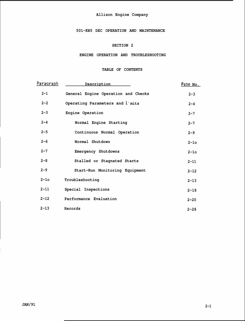
2-1
2-2
2-3
2-4
2-5
2-6
2-7
2-8
2-9
2-1o
2-11
2-12
2-13
Allison Engine Company
501-KB5 DEC OPERATION AND MAINTENANCE
SECTION 2
ENGINE OPERATION AND TROUBLESHOOTING
TABLE OF CONTENTS
Description
General Engine Operation and Checks
Operating Parameters and L
Engine Operation
Normal Engine Starting
mits
Continuous Normal Operation
Normal Shutdown
Emergency Shutdowns
Stalled or Stagnated Starts
Start-Run Monitoring Equipment
Troubleshooting
Special Inspections
Performance Evaluation
Records
Paqe No.
2-3
2-4
2-7
2-7
2-9
2-1o
2-1o
2-11
2-12
2-13
2-18
2-20
2-28
I
JAN/91 2-1
Allison Engine Company
501-KB5 DEc OpERATION AND MAINTENANCE
INDEX TO FIGURES
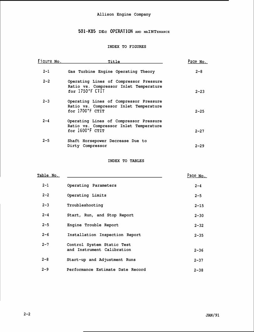
Fiqure No. Title
2-1
2-2
2-3
2-4
2-5
Table No.
2-1
2-2
2-3
2-4
2-5
2-6
2-7
2-8
2-9
Gas Turbine Engine Operating Theory
Operating Lines of Compressor PressureRatio vs. Compressor Inlet Temperaturefor 1750”F CTIT
Operating Lines of Compressor PressureRatio vs. Compressor Inlet Temperaturefor 1700”F CTIT
Operating Lines of Compressor PressureRatio vs. Compressor Inlet Temperaturefor 1600”F CTIT
Shaft Horsepower Decrease Due toDirty Compressor
INDEX TO TABLES
Operating Parameters
Operating Limits
Troubleshooting
Start, Run, and Stop Report
Engine Trouble Report
Installation Inspection Report
Control System Static Testand Instrument Calibration
Start-up and Adjustment Runs
Performance Estimate Date Record
Paqe No.
2-8
2-23
2-25
2-27
2-29
Paqe No.
2-4
2-5
2-15
2-30
2-32
2-35
2-36
2-37
2-38
2-2 JAN/91
2-1.
●
●
Allison Engine Company
501-KB5 DEC OPERATION AND MAINTENANCE
SECTION 2
ENGINE OPERATION AilD TROUBLESHOOTING
GENERAL ENGINE OPERATION AND CHECKS.
NOTE
This section is devoted to general engine operation and to thoseprecautionary checks to be made before starting the engine and afteroperation if problems are suspected.
All things are important, but a recheck of the following is stronglyrecommended for a-successful start and run.
A. Accomplish precautionary and prestart checks (Ref. OEM’s Manual).
B. Electrical power supply--2O to 29 vdc.
NOTE
Some engines have 200 psig (1378 kPag) gaseous fuel pressure.
C. Fuel, Gaseous Pressure -- Nominal 250 psig (1725 kPag) at the enginefuel metering valve inlet for nominal pipeline quality gas (Ref. toSection 4).
D. Fuel, Liquid Pressure -- Liquid fuel supply, pressure is produced byengine driven or an off engine motor pump (Ref. to Section 4).
CAUTION
ADEQUATE STARTER PRESSURE MUST BE MAINTAINED THROUGHOUT THE STARTERSUPPORT CYCLE. A FAULTY OR DETERIORATED STARTER OR LOW PRESSURE ORENERGY STARTER POWER SUPPLY MAY NOT ALLOW PROPER ENGINE START ANDACCELERATION. ENGINE DAMAGE CAN OCCUR THROUGH CONTINUED UNSATISFACTORYSTARTING ATTEMPTS.
NOTE
The starter assembly should have adequate torque. This can bedetermined by motoring the engine (with no ignition and fuel) to themaximum starter capability. This engine motoring speed should be atleast 3600 rpm. Accomplish this check periodically and on every occasionthat satisfactory engine starts cannot be obtained or whenever a starterdeficiency is suspected.
JAN/91 2-3
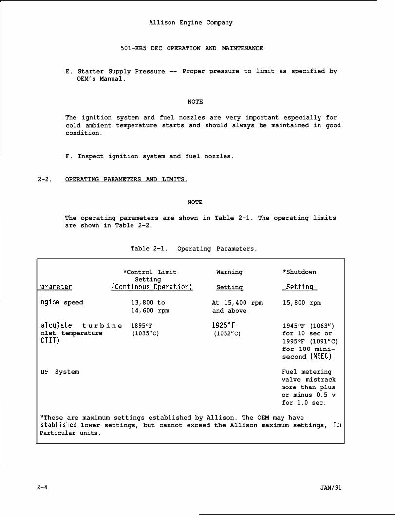
Allison Engine Company
501-KB5 DEC OPERATION AND MAINTENANCE
E. Starter Supply Pressure -- Proper pressure to limit as specified byOEM’s Manual.
NOTE
The ignitioncold ambientcondition.
system and fuel nozzles are very important especially fortemperature starts and should always be maintained in good
F. Inspect ignition system and fuel nozzles.
2-2. OPERATING PARAMETERS AND LIMITS.
L
NOTE
The operating parameters are shown in Table 2-1. The operating limitsare shown in Table 2-2.
Table 2-1. Operating Parameters.
*Control Limit Warning *ShutdownSetting
‘arameter (Continous O~eration) Settinq Settinq
:ngine speed 13,800 to At 15,400 rpm 15,800 rpm14,600 rpm and above
:alculate t u r b i n e 1895°F 1925°F 1945°F (1063”)nlet temperature (1035”C) (1052”C) for 10 sec orCTIT) 1995°F (1091”C)
for 100 mini-second (MSEC).
‘uel System Fuel meteringvalve mistrackmore than plusor minus 0.5 vfor 1.0 sec.
“These are maximum settings established by Allison. The OEM may havestablished lower settings, but cannot exceed the Allison maximum settings, forParticular units.
2-4 JAN/91
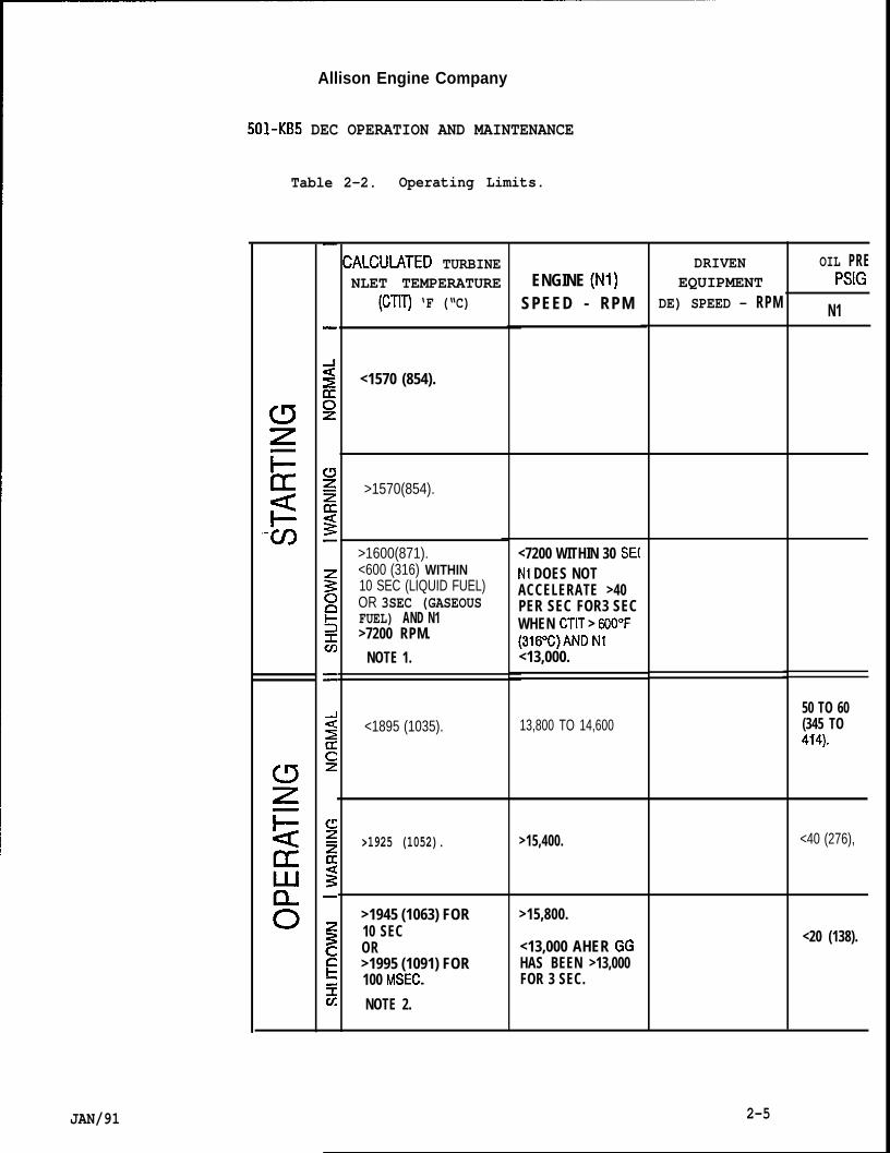
Allison Engine Company
501-KB5 DEC OPERATION AND MAINTENANCE
Table 2-2. Operating Limits.
“-U)
ALCULATED TURBINENLET TEMPERATURE
(CTIT) ‘F (“C)
<1570 (854).
>1570(854).
>1600(871).<600 (316) WITHIN10 SEC (LIQUID FUEL)OR 3SEC (GASEOUSFUEL) AND N1>7200 RPM.
NOTE 1.
<1895 (1035).
>1925 (1052).
>1945 (1063) FOR10 SECOR>1995 (1091) FOR100 MSEC.
NOTE 2.
ENGINE (Nl)SPEED - RPM
<7200 WITHIN 30 SE(N1 DOES NOTACCELERATE >40PER SEC FOR3 SECWHEN CTIT > 600”F(316”C)AND N1<13,000.
13,800 TO 14,600
>15,400.
>15,800.
<13,000 AHER GGHAS BEEN >13,000FOR 3 SEC.
DRIVENEQUIPMENT
DE) SPEED - RPM
OIL PREPSIG
N1
50 TO 60(345 TO414).
<40 (276),
<20 (138).
JAN/91 2-5
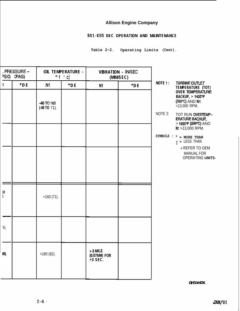
.PRESSURE-
——
jO)
‘6).
w),
(PAG)
* D E
OIL TEMPERATURE -‘F
N1
-40 T0160(-40 TO 71).
<160 (71).
>180 (82).
0 c)* D E
Allison Engine Company
501-KB5 DEC OPERATION AND MAINTENANCE
Table 2-2. Operating Limits
VIBRATION - lN/SEC(MM/SEC)
N1
>3MILS(0.07MM) FOR>3 SEC.
* D E
(Cent).
NOTE 1:
NOTE 2:
tiRBINEOtJTLETTEMPERATURE (TOT)OVER TEMPERATLIREBACKUP, > 1400°F(760”C) AND NI<13,000 RPM.
TOT RUN OVERTEMP-ERATUREBACKUP,> 1650°F (899°C) ANDN1 >13,000 RPM.
SYMBOLS : > = MORE THAN< = LESS THAN*
= REFER TO OEMMANUAL FOR
OPERATING UMITS-
Allison Engine Company
501 -KB5 DEC OPERATION AND MAINTENANCE
2-3. ENGINE OPERATION.
A.
B.
c.
Ouring starting, fuel and ignition are programmed by the controlsystem. Refer to the particular control system section for adescription of how this is accomplished. Overspeed, underspeed andtemperature protection is provided to the engine to initiate ashutdown. Other safety circuits connected to safety devices such aslow oil pressure or high vibration sensors can also initiate ashutdown in order to protect the engine (Ref. Tables 2-1 and 2-2).
Many safety circuits remain active during normal operation.
The gas turbine engine is essentially a heat engine using air as aworking fluid. Air-passing through the engine ii accelerated whichmeans that the kinetic energy of the air is increased. To obtainthis, the pressure energy is first increased and then heat energy isadded with the final conversion back to kinetic energy in the form ofa high velocity, high energy gas stream which is impinged on theturbine rotor assembly. Refer to the working cycle pressure volumediagram in Figure 2-1 with the following explanation:
1. Point X represents air at atmospheric pressure which is compressedalong line XY, which adds some heat.
2. From Y to Z more heat is added to the air by introducing andburning fuel at constant pressure; this increases the temperatureand volume of air. Some pressure losses occur in the combustionchamber as indicated by the drop between Y and Z.
3. From Z to X’the hot gases expand through the turbine nozzle (jeipipe or augmenter) and exhaust system to atmosphere. The kinet”(gas) energy is converted to mechanical work in the turbine andmanifested as torque at the PTO shaft output spline.
2-4. NORMAL
A. The
B. Eng
C. The
ENGINE STARTING.
starter begins to rotate the engine.
ne rpm and oil pressure begin to increase.
control system beqins to set the fue- metering valve in thethe fuel metering valve tocorrect position for ;tarting and tracks
verify the correct setting.
NOTE
If turbine temperature does not reach 600”F (316”C) CTIT and engine
c
speed is not more than 2200 rpm in 10 seconds for liquid fuel or 3seconds for gaseous fuel, an automatic engine (fail to fire) shutdownwill occur.
JAN/91 2-7
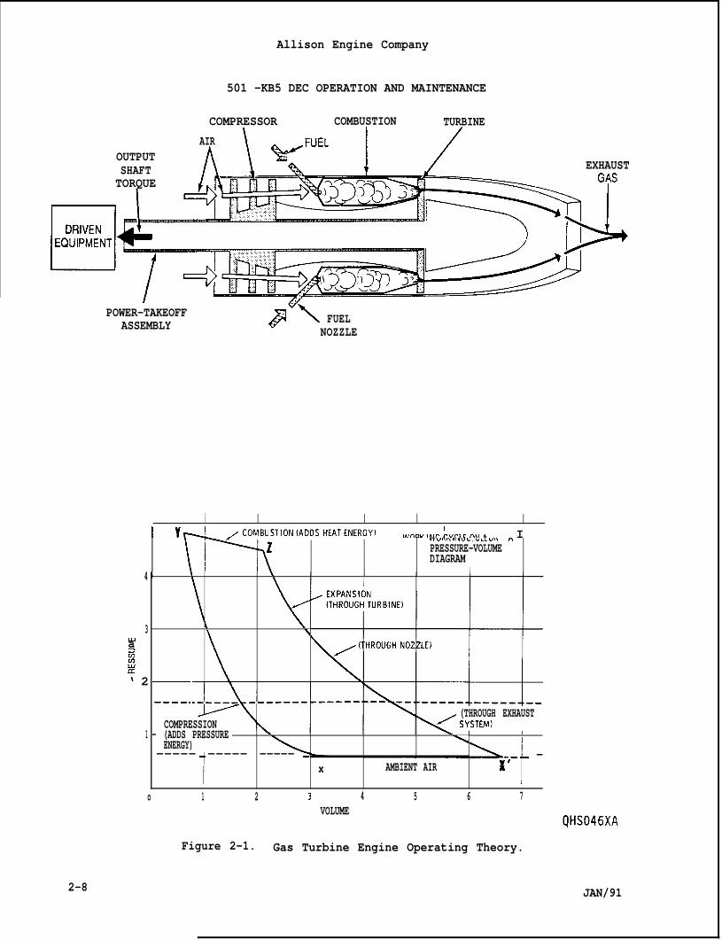
Allison Engine Company
501 -KB5 DEC OPERATION AND MAINTENANCE
COMPRESSOR COMBUSTION TURBINEAIR
OUTPUTSHAFT EXHAUSTTORQUE
POWER-TAKEOFFASSEMBLY px FUEL
NOZZLE
I Yd /coMBusTloN(ADDsH~TENERGyt I w-w,w.:vr-,rn,,. I
\r-N
VV”nn, l”u 1, , LLL “1” nPRESSURE-VOLUMEDIAGRAM
I4 I 1 \ 1
3 il-u \azCn2u‘ 2
(THROUGH EXHAUSTCOMPRESSION
1 – (ADDS PRESSUREENERGY) A
-----
1
----- ----- -
W
-,- - -x AMBIENT AIR x
o 1 2 3 4 5 6 7VOLUME
JAN/91
Figure 2-1. Gas Turbine Engine Operating Theory.
2-8
Allison Engine Company
501-KB5 DEC OPERATION AND MAINTENANCE
D. At 2200 engine rpm, the control system turns on the ignition andopens the fuel shutoff valve(s). The liquid fuel manifold drainvalves are closed (de-energized). Engine ignition (lightoff) occursand the engine should accelerate to running speed within one (1)minute.
CAUTION
ALTHOUGH ENGINE STARTS ARE PERMITTED AT ANY RESIDUAL TURBINETEMPERATURE, IF POSSIBLE ALLOW ENGINE TO COOL TO 200”F (93”C) PRIOR TOTHE NEXT START.
E. At 8400 engine rpm, the control system turns off ignition (if notturned off earlier by a timer) and starter systems.
NOTE
Engines having exceeding the one minute time period should beinvestigated for possible starting problem.
F. The engine should normally accelerate to operating speed within one(1) minute. The engine should be shutdown either manually or by thecontrol system if start cycle time is more than 45 seconds to reachoperating engine rpm from 2200 rpm. The control system will initiatea shutdown if engine acceleration rpm increases less than 40 rpm persecond for a 3 second time period and speed is less than 13,000 rpm.
NOTE
If the bleed valves are not open below 12,225 engine rpmwith 59°F(15”C) compressor inlet temperature (CIT), compressor surge and stal 1will occur. This can damage the engine. Note and evaluate any deviationfrom the operation described above in order to initiate propercorrective action.
G. Up to 11,000 engine rpm the compressor bleed valves are fully open tounload the compressor. At this speed they begin to move to the closedposition. At approximately 12,225 engine rpm, they are fully closed.These speeds are for 59°F (15”C) compressor inlet temperature (CIT),activation speeds vary with CIT. The reverse occurs duringdeceleration to idle or shutdown. If the preceding limits are notmet, refer to Section 11, Compressor Bleed System, for correctiveprocedures and/or refer to Troubleshooting (Ref. Table 2-3).
2-5. CONTINUOUS NORMAL OPERATION.
A. The engine will operate between 13,800 and 14,600 rpm to satisfy theload requirements of the driven equipment.
JAN/91 2-9
2-6.
.
.
.
2-7.
2-1o
Allison Engine Company
501-KB5 DEC OPERATION AND MAINTENANCE
B. Maximum continuous CTIT is 1895°F (1035”C).
C. Less than 1.0 mil (0.023 mm) engine turbine vibration is normal.Vibration above 1.0 mil (0.023 mm) a warning condition is given andcorrective action is required.
D. Engine oil pressure is 50-60 psig (345-414 kPag) and oil temperatureat the inlet to the engine should be less than 160”F (71”C).
NORMAL SHUTDOWN.
CAUTION
STABILIZED RUNNING IS PROHIBITED AT SPEEDS BELOW THE IDLE SPEED. THECONTROL SYSTEM IS DESIGNED TO PREVENT ENGINE OPERATION BELOW 13,000RPM .
NOTE
Safeguards built into the engine control system to prevent enginedamage are listed and explained in the applicable control systemsection.
Compare starting difficulty symptoms with descriptions tabulated inthe control system section; refer there for details in order todetermine the malfunctioning item.
Normal shutdown should include a minimum of 5 minutes operation atidle rpm after operation at more than 1450”F (788”C) CTIT.
A.
B.
c.
A signal is initiated which closes the fuel shutoff valve.
As fuel is completely shutoff, the flame extinguishes, and the enginecoasts down to zero rpm in a smooth manner.
Engine oil pressure declines to O psig (O kPag) as the engine comesto a stop.
EMERGENCY SHUTDOWNS.
NOTE
During an emergency shutdown, all functions associated with a normalshutdown occur except for the time at idle and that they occur in rapidsequence. An emergency shutdown will be initiated by the control systemor should be manually initiated if any of the following limitingconditions occur:
A. CTIT is more than 1945°F (1063”C) for more than 10 seconds or 1995eF(1091”C) for 100 milliseconds. Automatic shutdown will occur.
JAN/91
Allison Engine Company
501-KB5 DEC OPERATION AND MAINTENANCE
B. CTIT is less than 600”F (316”C). (This could occur due to athermocouple signal loss or a flameout.)
C. Engine speed is more than 15,800 rpm or less than 13,000 rpm.
D. Engine oil pressure is less than 20 psig (138 kPag).
E. Engine vibrations is more than 3.0 roils (0.07 mm) for a 3 second timeperiod.
F. Driven equipment vibration is more than established by the OEMmanual .
G. Driven equipment bearing temperatures refer to OEM for limits.
H. Driven equipment oil supply pressure refer to OEM for limits.
I. Fuel metering valve mistracks the fuel demand by more than a plus orminus 0.5 volt for 1.0 second.
2-8. STALLED OR STAGNATED STARTS.
A.
B.
c.
D.
E.
F.
G.
H.
I.
J.
NOTE
The following items can contribute to a stalled start:
Not enough fuel supply to keep the engine accelerating.
Low fuel supply pressure.
Fuel shutoff valve(s) not completely open.
In-line fuel filter blocked, collapsed, or dirty.
Fuel metering valve (FMV) stuck closed or partially open (the FMVtracking will abort the start due to mistracking).
Loose fitting or broken fuel lines (leakage).
Blocked fuel nozzles.
Improper signal from the CIT sensor to the control system.
Engine speed pickup is faulty.
Excess fuel which chokes the engine causes partial compressor stalland prevents acceleration:
1. Turbine airfoils are damaged and general hot section damage.
JAN/91 2-11
Allison Engine Company
501-KB5 DEC OPERATION AND MAINTENANCE
2. Compressor blading is damaged or badly contaminated (dirty).
3. Control system starting fuel flow schedule too high due to amalfunction of a component.
K. Air inlet or exhaust system blocked.
1. Inlet louvers not opening.
2. Inlet duct collapsed,
3. Foreign material
4. Foreign material
5. The exhaust duct
L. Exhaust gas blowing
M. Insufficient assist
covering the inlet air filter opening.
blocking the engine air inlet.
blocked by foreign material.
directly into the air inlet.
(driving force) from the starter:
1. Supply pressure too low.
2. Starter is worn or damaged.
3. Starter has too low a horsepower rating.
4. Starter drive is slipping (stripped side gear or mating gear).
CAUTION
IF BLEED VALVES ARE CLOSED ON START NOT ONLY WILL THERE BE A STALL BUTALSOAN 0VERTE14PERATURE CONDITION AND ENGINE DAMAGE WILL OCCUR.
N. Compressor bleed valves are closed on start.
2-9. START-RUN MONITORING EQUIPMENT.
A. Refer to the instrumentationengine. The following is theeach engine:
nstalled in the control panel for theminimum instrumentation required for
1.
2.
3.
2-12
CTIT meter.
Engine speed meter.
Control system operating lights (Refer to Section 6, ControlSystem).
JAN/91
4.
5.
6.
7.
8.
Allison Engine Company
501-KB5 DEC OPERATION AND MAINTENANCE
Operating condition indicators (normally lights or flags) toindicate a warning or emergency shutdown condition. Othercondition status which may be displayed are:
a. Power applied to Starter Relay.
b. Fuel ON.
c. Rundown timer.
d. Magnetic chip detector.
Engine and/or driven equipment oil pressures.
Fuel supply pressure at the fuel metering valve inlet.
Vibration meters.
CIT meter.
B. For additional information regarding speed pickups, vibration pickupsand other sensors, refer to those specific sections which deal withthese in detail.
C. Refer to Paragraph 2-12, Performance Evaluation for correct turbineoperation.
2-10. TROUBLESHOOTING.
A. General.
NOTE
The DEC control system may interrogated to identify the malfunctionshutdown.
1. When a malfunction is suspected, try initially to locate the faultwith the equipment in the static state. (Engine not running,electrical power OFF, etc.)
2. Do not set up the prevailing conditions under which a malfunctionoccurred, in order to see if it will appear again, until somelogical inspection has been made that may show what went wrong.
3. If it is possible during static checks, isolate assemblies and/orcomponents and inspect them individually. Take precautions toprotect one unit from another where there is some interlink whileeither is being tested.
4. Observe and record indexing, spatial distances, and other special
JAN/91 2-13
Allison Engine Company
501-KB5 DEC OPERATION AND MAINTENANCE
linkages when components are detached from eachcalibration can be attained upon reassembly.
other so correct
5. Certain problems can be detected (or more easily detected) onlywhen a device is being operated. If it is possible, rig the testto turn on sections of the system one at a time, checking each forcorrect operation before proceeding to the next.
6. Introduce the necessary signals (electrical, pressure, tempera-ture, rpm) keeping rigid control of them, into the suspected area,and observe the results. What to expect as a response must beknown. Use the schematics (such as those in the”501-KB5 Installa-tion Drawing, 23037500) as well as specific component informationto determine what is to be expected, then, test for it. Also,compare data with standard operating data acquired earlier.
7. If the action generated by the preceding suggestions of Steps 1.thru 6. does not reveal the Droblem. reassemble, read.iust, recali-brate and rerun the orand watch carefully topersists.
8. The Troubleshooting Guwith some of the kinds
ginal’system’as a unit. ‘Take ~ynarnic datasee if the malfunction reoccurs and
de, Table 2-3, is to acquaint the operatorof difficulties that could be encountered.
9. Operator personnel should become acquainted with the principalsand basics of aas turbine enaine oDeration. Troubleshootina will
J. . -,.. .
then be easier-and logical.
10. Maintain a historical record of engine performance. This willthen provide a baseline for monitoring changes in engineperformance, especially when a problem is suspected. Thehistorical record will shows trends, for example, thecompressor becoming dirty.
B. Troubleshooting Charts, Graphs, and Tables.
1. The troubleshooting information that follows is an outline orguide. It is not practical to list or to point out every possibleoperating problem. There are also differences between installa-tions; making exact details difficult. The Operator should createtroubleshooting charts to cover their specific installations.Refer to Table 2-3.
2. Additional troubleshooting information and techniques are in othersections. Others that may be useful are:
a. Section 7, Engine Lubrication, Table 7-1, Oil Leaks.
b. Performance Evaluation, Paragraph 2-12.
2-14
c. Section 5, Turbine Outlet Temperature (TOT) System.
JAN/91
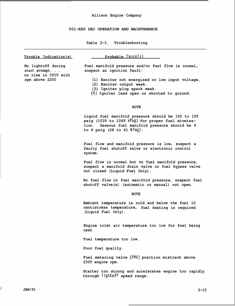
Allison Engine Company
501-KB5 DEC OPERATION AND MAINTENANCE
Table 2-3. Troubleshooting
Trouble Indication(s) Probable Cause(s)
No lightoff during Fuel manifold pressure and/or fuel flow is normal,start attempt. . . suspect an ignition fault:no rise in CTIT withrpm above 2200 (1) Exciter not energized or low input voltage.
(2) Exciter output weak.(3) Igniter plug spark weak.(4) Igniter lead open or shorted to ground.
NOTE
Liquid fuel manifold pressure should be 150 to 155psig (1035 to 1069 kPag) for proper fuel atomiza-tion. Gaseous fuel manifold pressure should be 4to 6 psig (28 to 41 kPag).
Fuel flow and manifold pressure is low, suspect afaulty fuel shutoff valve or electronic controlsystem.
Fuel flow is normal but no fuel manifold pressure,suspect a manifold drain valve or fuel bypass valvenot closed (Liquid Fuel Only).
No fuel flow or fuel manifold pressure, suspect fuelshutoff valve(s) (automatic or manual) not open.
NOTE
Ambient temperature is cold and below the fuel 10centistokes temperature, fuel heating is required(Liquid Fuel Only).
Engine inlet air temperature too low for fuel beingused.
Fuel temperature too low.
Poor fuel quality.
Fuel metering valve (FMV) position mistrack above2300 engine rpm.
Starter too strong and accelerates engine too rapidlythrough lightoff speed range.
2-15I JAN/91
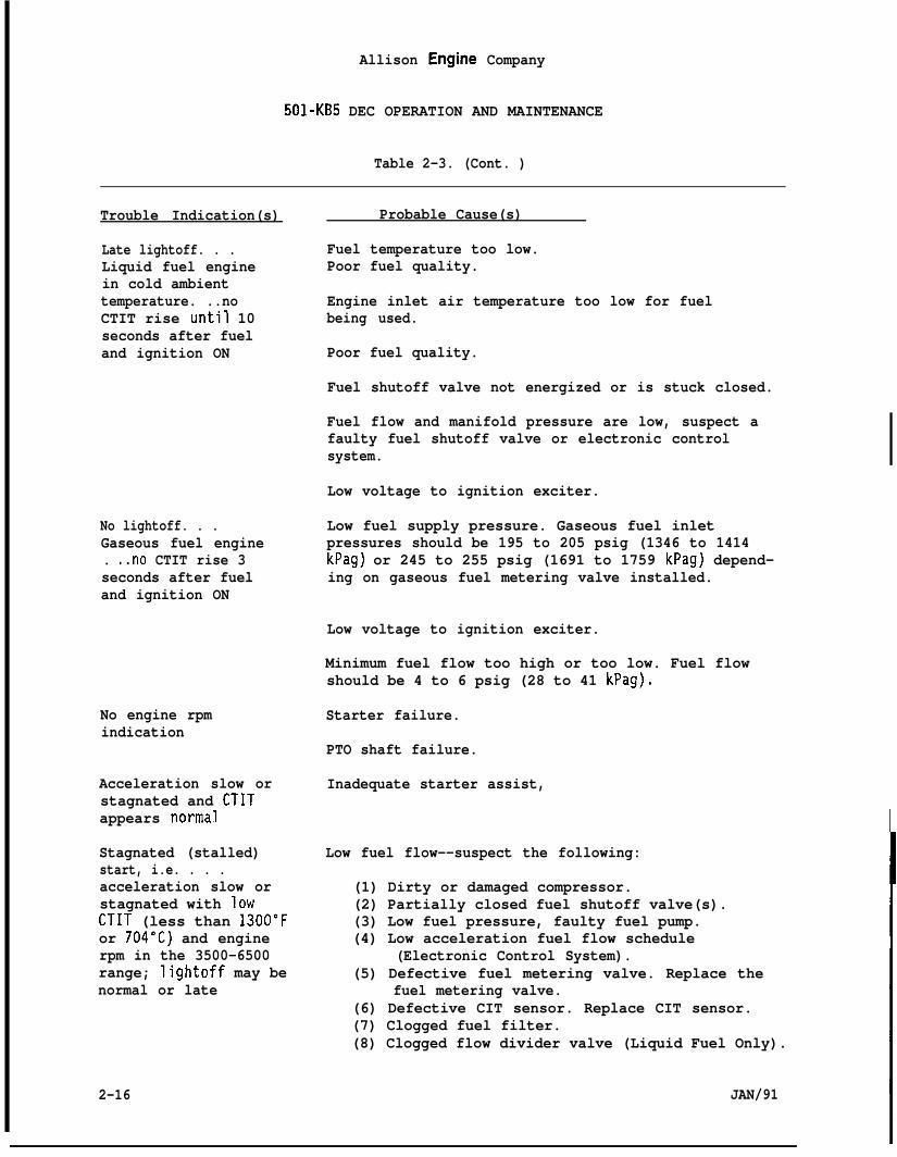
Allison Engine Company
501-KB5 DEC OPERATION AND MAINTENANCE
Table 2-3. (Cont. )
Trouble Indication(s)
Late lightoff. . .Liquid fuel enginein cold ambienttemperature. ..noCTIT rise until 10seconds after fueland ignition ON
No lightoff. . .Gaseous fuel engine. ..no CTIT rise 3seconds after fueland ignition ON
No engine rpmindication
Acceleration slow orstagnated and CTITappears normal
Stagnated (stalled)start, i.e. . . .acceleration slow orstagnated with lowCTIT (less than 1300”For 704’C) and enginerpm in the 3500-6500range; Iightoff may benormal or late
Probable Cause(s)
Fuel temperature too low.Poor fuel quality.
Engine inlet air temperature too low for fuelbeing used.
Poor fuel quality.
Fuel shutoff valve not energized or is stuck closed.
Fuel flow and manifold pressure are low, suspect afaulty fuel shutoff valve or electronic controlsystem.
Low voltage to ignition exciter.
Low fuel supply pressure. Gaseous fuel inletpressures should be 195 to 205 psig (1346 to 1414kPag) or 245 to 255 psig (1691 to 1759 kPag) depend-ing on gaseous fuel metering valve installed.
Low voltage to ignition exciter.
Minimum fuel flow too high or too low. Fuel flowshould be 4 to 6 psig (28 to 41 kPag).
Starter failure.
PTO shaft failure.
Inadequate starter assist,
Low fuel flow--suspect the following:
(1) Dirty or damaged compressor.(2) Partially closed fuel shutoff valve(s).(3) Low fuel pressure, faulty fuel pump.(4) Low acceleration fuel flow schedule
(Electronic Control System).(5) Defective fuel metering valve. Replace the
fuel metering valve.(6) Defective CIT sensor. Replace CIT sensor.(7) Clogged fuel filter.(8) Clogged flow divider valve (Liquid Fuel Only).
2-16 JAN/91
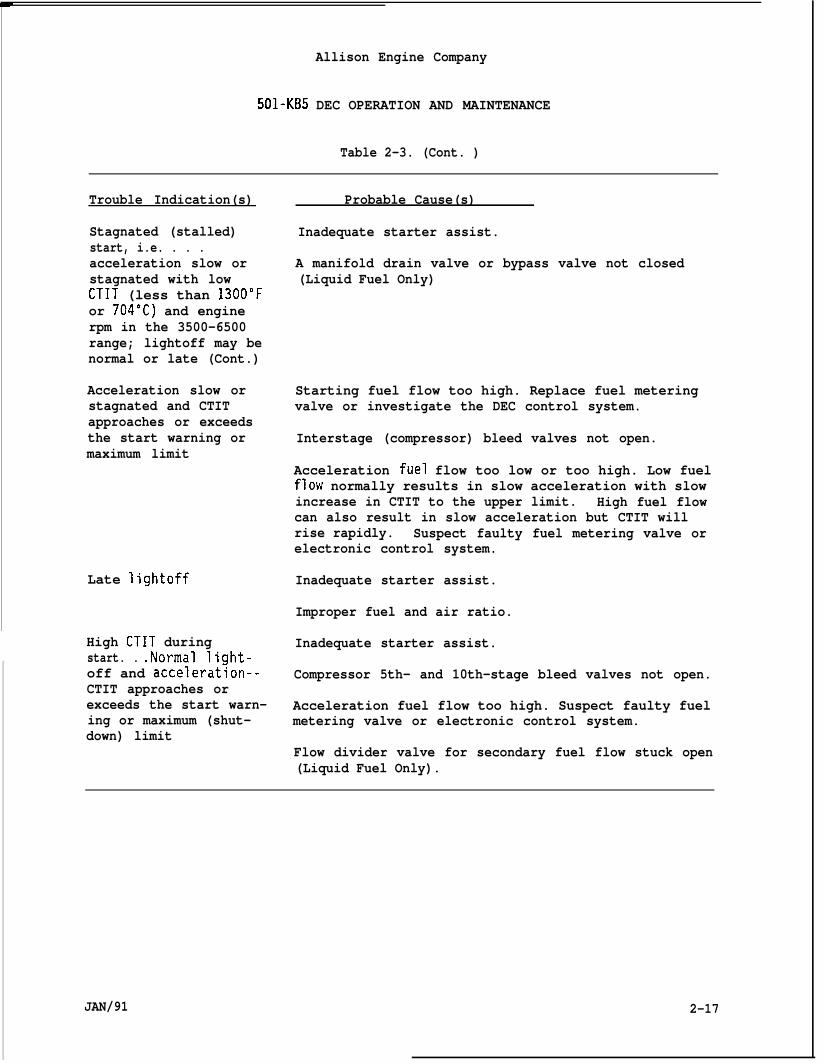
Allison Engine Company
501-KB5 DEC OPERATION AND MAINTENANCE
Table 2-3. (Cont. )
Trouble Indication(s)
Stagnated (stalled)start, i.e. . . .acceleration slow orstagnated with lowCTIT (less than 1300”For 704”C) and enginerpm in the 3500-6500range; lightoff may benormal or late (Cont.)
Acceleration slow orstagnated and CTITapproaches or exceedsthe start warning ormaximum limit
Late lightoff
High CTIT duringstart. . .Normal light-off and acceleration--CTIT approaches orexceeds the start warn-ing or maximum (shut-down) limit
Probable Cause(s)
Inadequate starter assist.
A manifold drain valve or bypass valve not closed(Liquid Fuel Only)
Starting fuel flow too high. Replace fuel meteringvalve or investigate the DEC control system.
Interstage (compressor) bleed valves not open.
Acceleration fuel flow too low or too high. Low fuelflow normally results in slow acceleration with slowincrease in CTIT to the upper limit. High fuel flowcan also result in slow acceleration but CTIT willrise rapidly. Suspect faulty fuel metering valve orelectronic control system.
Inadequate starter assist.
Improper fuel and air ratio.
Inadequate starter assist.
Compressor 5th- and 10th-stage bleed valves not open.
Acceleration fuel flow too high. Suspect faulty fuelmetering valve or electronic control system.
Flow divider valve for secondary fuel flow stuck open(Liquid Fuel Only).
JAN/91 2-17
Allison Engine Company
501-KB5 DEC OPERATION AND MAINTENANCE
C. Test Equipment and Techniques for Troubleshooting
1.
D. Oi”
Referor Dr
The borescope is used to visually inspect the internal areas ofthe combustion section, fuel nozzle heads and turbine inlet. Itis also convenient for probing into other places such as thecompressor inlet. (Ref. Section 3, General Engine Inspection andMaintenance Tasks.)
Consumption Troubleshooting.
NOTE
to Section 7, Engine Lubrication for troubleshooting proceduresven Equipment OEM manual.
2-11. SPECIAL INSPECTIONS.
A.
B.
c.
Special inspections are usually those which come about because of amalfunction or a pending malfunction as indicated by a warning.Refer to appropriate manual sections.
Vibration limit is exceeded and a shutdown may or may not haveresulted:
1.
2.
3.
Check for loose pickup, mounting plate or connector. Check thewiring to the pickup connector.
Check magnetic chip detector for debris accumulation.
Restart engine. If the limits are exceeded again, check compressorand turbine for damage.
Automatic shutdown occurs during engine start:
1. If three consecutive start attempts are unsatisfactory, determinecause.
2. Inspect fuel and electronic control systems.
3. Inspect for fuel metering valve mistrack and electronic controlsystem.
4. Inspect engine oil system (Ref. Section 7).
5. Inspect turbine and compressor by the use of a borescopeSection 3).
Ref.
6. Inspect for disconnected engine harness, reconnect if required.
2-18
7. Inspect for open circuit in thermocouple wiring from engine toelectronic control system.
JAN/91
D.
E.
F.
Allison Engine Company
501 -KB5 DEC OPERATION AND MAINTENANCE
Automatic overtemperature shutdown occurs during starting or durnormal operation:
1. Inspect fuel, DEC electronic control, and thermocouple circuitsystems.
2. Inspect turbine and compressor by the use of a borescope.
3. Check 5th and 10th bleed valve operation.
Automatic overspeed shutdown occurs.
Magnetic drain plug - continuity established between contacts.
ng
NOTE
Remove and inspect magnetic drain plug for metal particleaccumulation. Refer Section 7.
G. Engine power has depreciated.
WARNING
IF BLEED VALVES ARE NOT CLOSING, THE BLEED VALVE CAN BE HOT AND CANBURN MAINTENANCE PERSONNEL IF TOUCHED.
1.
2.
Make sure compressor bleed valves are fully closing. A quick checkis to make sure bleed valves are not too hot to the touch.
Inspect compressor for dirty bladina. If so. clean thecompressor.” Try water, liq~id clea~er, and-ground nut shell,kerosene, and steam. Refer to Section 11, Compressor Section.Check engine performance.
H. Inspect fuel filter delta pressure. A dirty filter with a highpressure drop will restrict fuel flow.
I. Inspect burner drain valves (Liquid Fuel Only).
1. At the time of compressor cleaning, determine that burner drainvalves are operational.
2. Refer to burner drain valve section for running inspection.
J. Inspect turbine 1st stage vanes and blades for heat damage by using aborescope through several of 18 inspection ports in turbine inletcase.
JAN/91 2-19
—
Allison Engine Company
501-KB5 DEC OPERATION AND MAINTENANCE
2-12. PERFORMANCE EVALUATION .
A. General.NOTE
In most applications there is no way to obtain complete data necessaryto exactly calculate engine performance. However decreased compressorefficiency often due to ingested oil vapors, dirt, or other airbornecontaminates can be determined by a comparative performance method.This method requires that a complete engine baseline of data is recordedand kept whenever a new and/or a replacement engine is installed, orwhenever an engine has undergone a major on-site repair, such as turbineunit change. Future data, such as the Performance Estimate Data Record,Gas Turbine Trouble Report, etc, will use the engine baseline data forestimating a decrease in performance.
1. Use the engine baseline to estimate performance of the engine(s).
NOTE
If compressor damage such as blade erosion or vane erosion or foreignobject damage (FOD) has not occurred, the performance can normally berecovered by cleaning the compressor.
2. Cleaning or other maintenance is highly recommended by Allisonwhen performance depreciates 5 percent below the baseline.
CAUTION
ENGINE PERFORMANCE THAT DECREASE IN EXCESS OF 5 PERCENT IS TO BEAVOIDED, SINCE THE ACCOMPANYING INCREASE IN CTIT LEVEL REDUCES TURBINELIFE.
3. The compressor cleaning methods, described in Section 10, areconditions and times to accomplish cleaning recommended byAllison. The gas turbine engine owner may modify these cleanmethods to suit the particular type operating conditions.Excessive performance depreciation (5 percent below the baselcan lead to starting difficulties and turbine damage.
2-20
NOTE
the
ng
ne)
Since the calculated turbine inlet temperature (CTIT) is held constantfor the baseline and the subsequent performance checks, it is advisableto inspect the thermocouples for integrity as well as all the thermo-couple indicating circuitry prior to running a performance check.
JAN/91 ---1
4. To
a.
b.
c.
d.
Allison Engine Company
501 -KB5 DEC OPERATION AND MAINTENANCE
determine engine performance use the following graphs.
Operating Lines of Compressor Pressure Ratio Versus CompressorInlet Temperature for 1750”F (954”C) CTIT (Ref. Figure 2-2).
Operating Lines of Compressor Pressure Ratio Versus CompressorInlet Temperature for 1700”F (927”C) CTIT (Ref. Figure 2-3).
Operating Line of Compressor Pressure Ratio Versus CompressorInlet Temperature for 1600”F (871”C) CTIT (Ref. Figure 2-4).
Shaft Horsepower Decrease Due to Dirty Compressor (Ref. Figure2-5).
B. Estimate of Percent Decrease of Shaft Horsepower.
1.
2.
The basic principle is to compare the differential pressure acrossthe compressor with that measured at subsequent performancechecks.
The pressures and temperature should be taken at the same enginelocations (stations) for each performance check. Also, theinstrumentation used in recording the data should be incalibration. All instruments should have at least a fl% fullscale accuracy.
C. Procedure to Estimate Decrease of Shaft Horsepower.
NOTE
Should operating power restrictions limit the maximum CTIT at which theengine can be operated, a lower CTIT can be used as a stabilized powercheck point condition orovidina the compressor bleed valves are fullvclosed_. A graph for operating % 1700”F’(927”C) CTIT (Ref. Figure Z-i)and 1600°F (871”C) CTIT (Ref. Figure 2-4) check points are provided
1. Start the engine and stabilize at 1750”F (954”C) CTIT. For thexample the operating lines are on Figure 2-2.
s
NOTE
CIT is sometimes written as Tt2. The graphs have been scribed for “Fwith added metric equivalents.
2. Record the following data.
a. Total compressor inlet temperature (CIT).
I JAN/91 2-21
I
Allison Engine Company
501-KB5 DEC OPERATION AND MAINTENANCE
NOTE
CIP is sometimes written as Pt2. Because of thepressure, best results can be obtained by measur”
nature of theng inches of water.
b. Total compressor inlet pressure (CIP).
NOTE
CDP is sometimes written as P4. Because of the high pressure,mercury (Hg) manometer and aneroid-type pressure gages are recommended.
c. Compressor discharge pressure (CDP).
NOTE
For this example the follow”
CDP= 288.5 in. HgCIP = 29.5 in. Hg
Hence: Rc =~= 288.5CIP 29.5
ng pressures have been chosen:
absolute (974 kPa)absolute (99.6 kPa)
(974) = 9.78(99.6)
NOTE
Since compressor performance (the differential pressure across thecompressor) is expressed as a ratio, the units of absolute pressurecould be psia (kPaa), etc. What matters is that for calculations boththe CIP and CDP must be in the same units.
3.
4.
5.
6.
7.
Determine the compressor ratio (Rc) by dividing compressordischarge pressure (CDP) by compressor inlet pressure (CIP) usingthe same absolute pressure units.
The compressor ratio of9.78 versus the CITof27°F (-2.8”C)chosen for this example is plotted as point A on Figure 2-3.
,The value of the compressor ratio (R ) from the baseline data isplotted as point o. ?For this exampe the CIT is 65°F (18.3”C)and Rc is 9.28.
Adjust the value of Rc, which is plotted at A , along aconstant operating line to the intersection of the CIT value ofthe comparative baseline which is 65eF (18.3”C) and plot thepointm . Record the (new) adjusted value of Rc, which in thisexample is 9.01 (Ref. Figure 2-2).
Compute the percent of R baseline by multiplying the adjustedvalue of RC (9.01) by 106 and dividing the product by the compara-tive basellne Rc (9.28). In this example, this is 97.09 percent.
2-22
—
JAN/91

Allison Engine Company “:.!,’
501-KB5 DEC OPERATION AND MAINTENANCE
(-34) (-29) (-23) (-18) ‘(-12) (-7) (-1) (4)
TOTAL COMPRESSOR INLET
Figure 2-2. Operating Lines of Compressor Pressure Ratio VersusCompressor Inlet Temperature for 1750”F (954”C) CTIT.
JAN/91 2-23
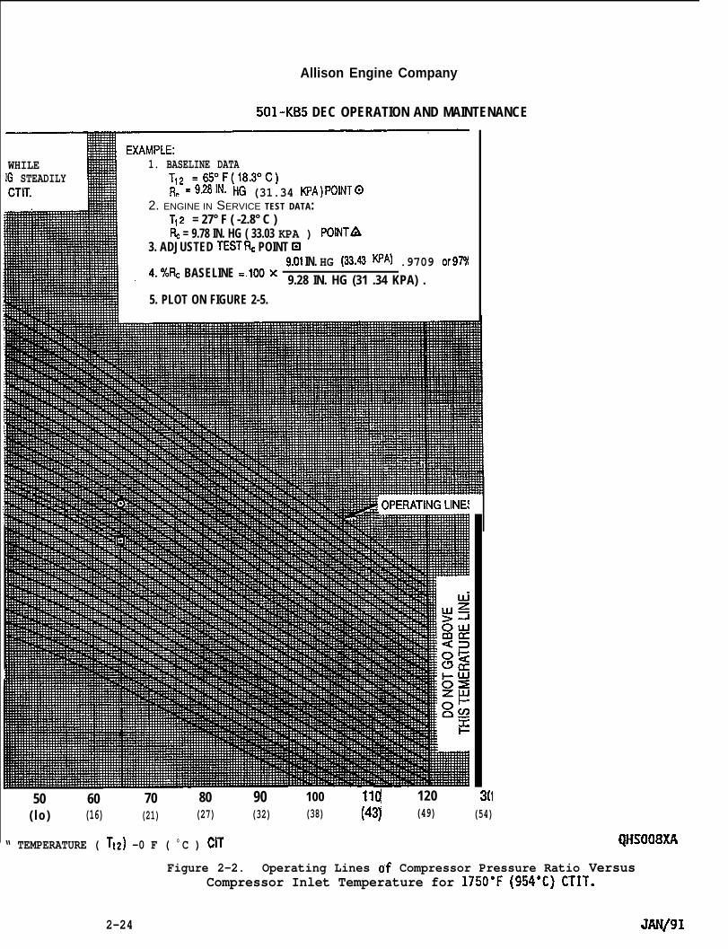
Allison Engine Company
501-KB5 DEC OPERATION AND MAINTENANCE
WHILE 1. BASELINE DATAIG STEADILYCTIT. R, =9.281N. HG (31.34 KPA)POlNT@
12. ENGINE IN SERVICE TEST DATA:
Tt z = 27° F ( -2.8° C )F& = 9.78 IN. HG ( 33.03 KPA ) POINTA
3. ADJUSTED TESTRC POINT El
4.%RC BASELINE =.1OOX9.01 IN. HG (33.43 ‘A) .9709 or97Y9.28 IN. HG (31 .34 KPA) .
5. PLOT ON FIGURE 2-5.
50 60 70 80 90 100 Il(j 120 1( lo ) (16) (21) (27) (32) (38) (43] (49) (54)
“ TEMPERATURE ( T~2) -0 F ( 0 C ) CIT QHSO08XA
Figure 2-2. Operating Lines of Compressor Pressure Ratio VersusCompressor Inlet Temperature for 1750”F (954’C) CTIT.
2-24 JAN/91
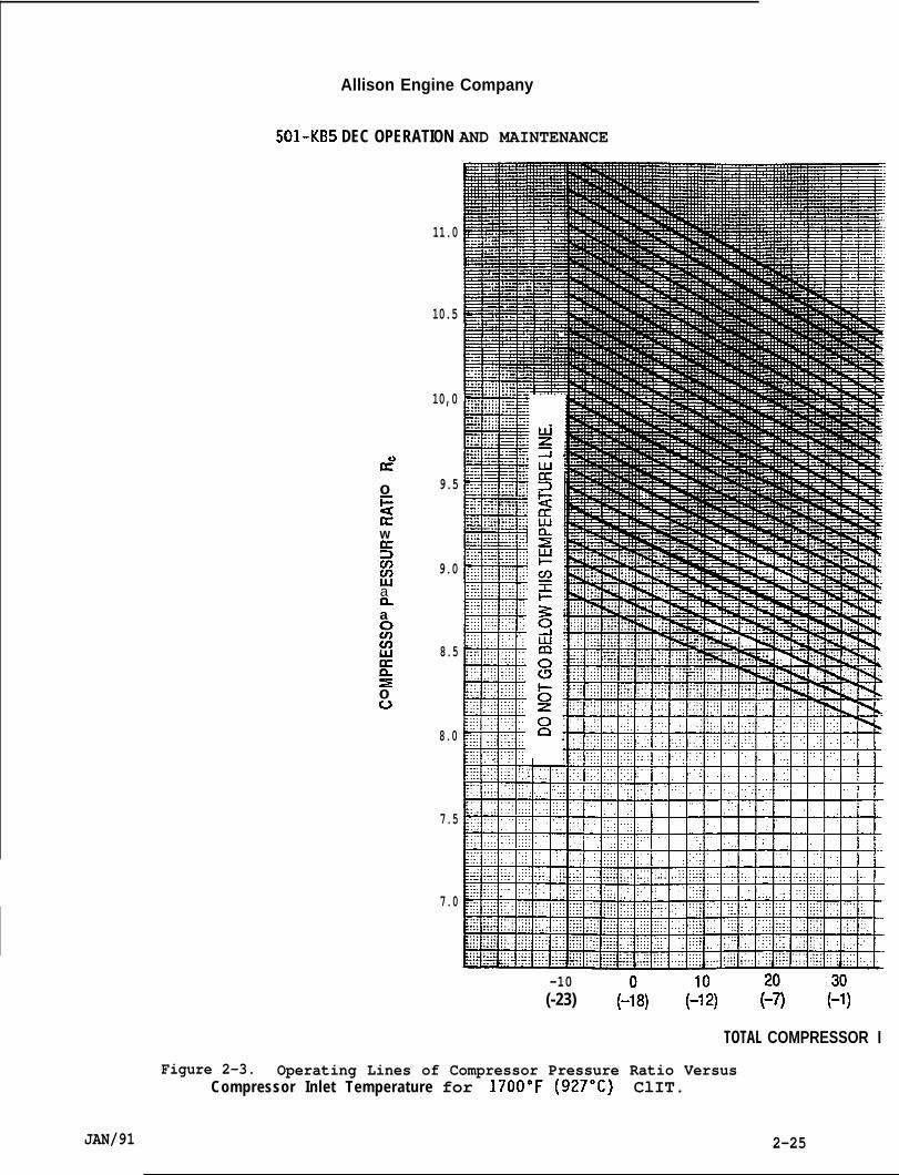
Allison Engine Company
501-K135 DEC OPERATION AND MAINTENANCE
Id”oi=uaw!3u)fJ
ana51fIJ
Eso0
11.0
10.5
10,0
9.5
9.0
8.5
8.0
7.5
7.0
-10(-23) (-:8) (::2) & (::)
TOTAL COMPRESSOR I
Figure 2-3. Operating Lines of Compressor Pressure Ratio VersusCompressor Inlet Temperature for 1700”F (927”C) ClIT.
JAN/91 2-25
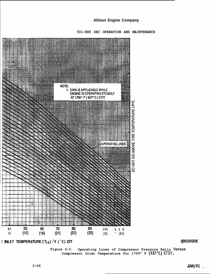
Allison Engine Company
501-KB5 DEC OPERATION AND MAINTENANCE
Uizi
40 100 1 1 0(4) (%) (%) & & ?2) (38) ‘ (43)
1 INLET TEMPERATURE ~Tt2) -0 F ( 0 C) CIT QttSO09XK
Figure 2-3. Operating Lines of Compressor Pressure Ratio VersusCompressor Inlet Temperature for 1700” F (927°C) CTIT.
2-26 JAN/91 -
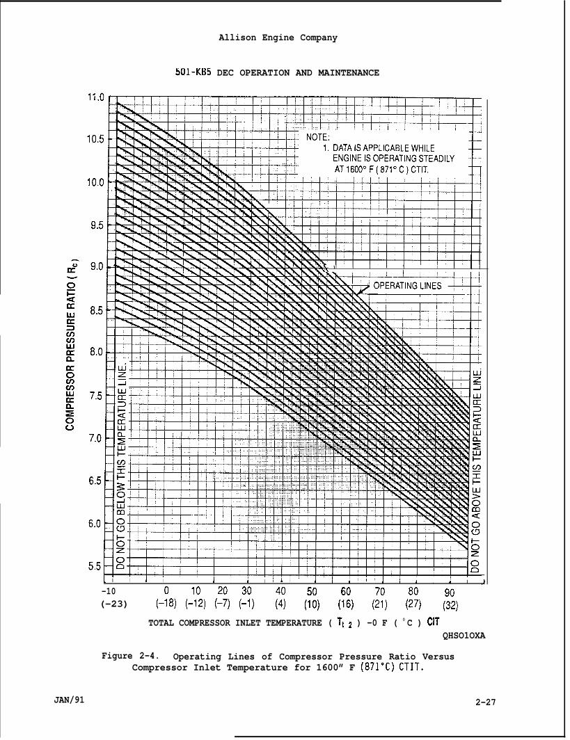
Allison Engine Company
5cJ1-KB5 DEC OPERATION AND MAINTENANCE
-- F
w-% ‘ 1 1 ) 1 I I1
I I I,
1 I I i I!,
i I i I ;, I I I 1 :,I
i I I I i I
-10(-23) (-:8) (!:2) (~?) (~:) I (%) (% ($ % ?2)
TOTAL COMPRESSOR INLET TEMPERATURE ( T~ ~ ) -0 F ( 0 C ) CITQHSO1OXA
Figure 2-4. Operating Lines of Compressor Pressure Ratio VersusCompressor Inlet Temperature for 1600” F (871”C) CTIT.
JAN/91 2-27
8,
9.
10.
Allison Engine Company
501-KB5 DEC OPERATION AND MAINTENANCE
Enter Figure 2-5 with the percent baseline R as determined bythe previous step and follow the line up to !he calculate turbineinlet temperature (CTIT) line. In this example, this is the1750”F (954”C) line (curve). The percent decrease in engine shafthorsepower is found at this point and is 5.4 percent.
When decrease in shaft horsepower (SHP) exceeds 5 percent,accomplish engine cleaning per Section 10, Compressor Section.
For keeping records as well as the procedure, use PERFORMANCEEVALUATION-DATA RECORD SHEET.
2-13. RECORDS.
NOTE
The importance of keeping accurate recordsand is strongly recommended by Allison.
cannot be over emphasized
A. Records are used as an aid to locate problems as well as to determinewhen maintenance is required.
B. This data can be useful in anal.yzinq oPeratin9 costs. Several kindsof
1.
2.
3.
technical records should be ~ons~dered: -
Those when the gas turbine engine and the driven equipment areoperating normally and efficiently.
Those when conditions indicate trouble or a when a malfunctionactually occurs (The Trouble Report).
A third set of records, eauall.y as important to the troubleshooteras well as for record purposes; are those which cover prestartchecks and proper adjustments.
C. The following data forms are recommended by Allison. Samples ofthese recommended forms follow.
1.
2.
30
4.
5.
6.
Start, Run, and Stop Report (Ref. Table 2-4).
The Trouble Report is used as a supplement the Start, Run, andStop Report when a malfunction occurs (Ref. Table 2-5).
Installation Inspection Report (Ref. Table 2-6).
Control System Static Test and Instrument Calibration (Ref. Table2-7).
Start-up and Adjustment Runs (Ref. Table 2-8).
Performance Estimate Data Record (Ref. Table 2-9).
2-28 JAN/91
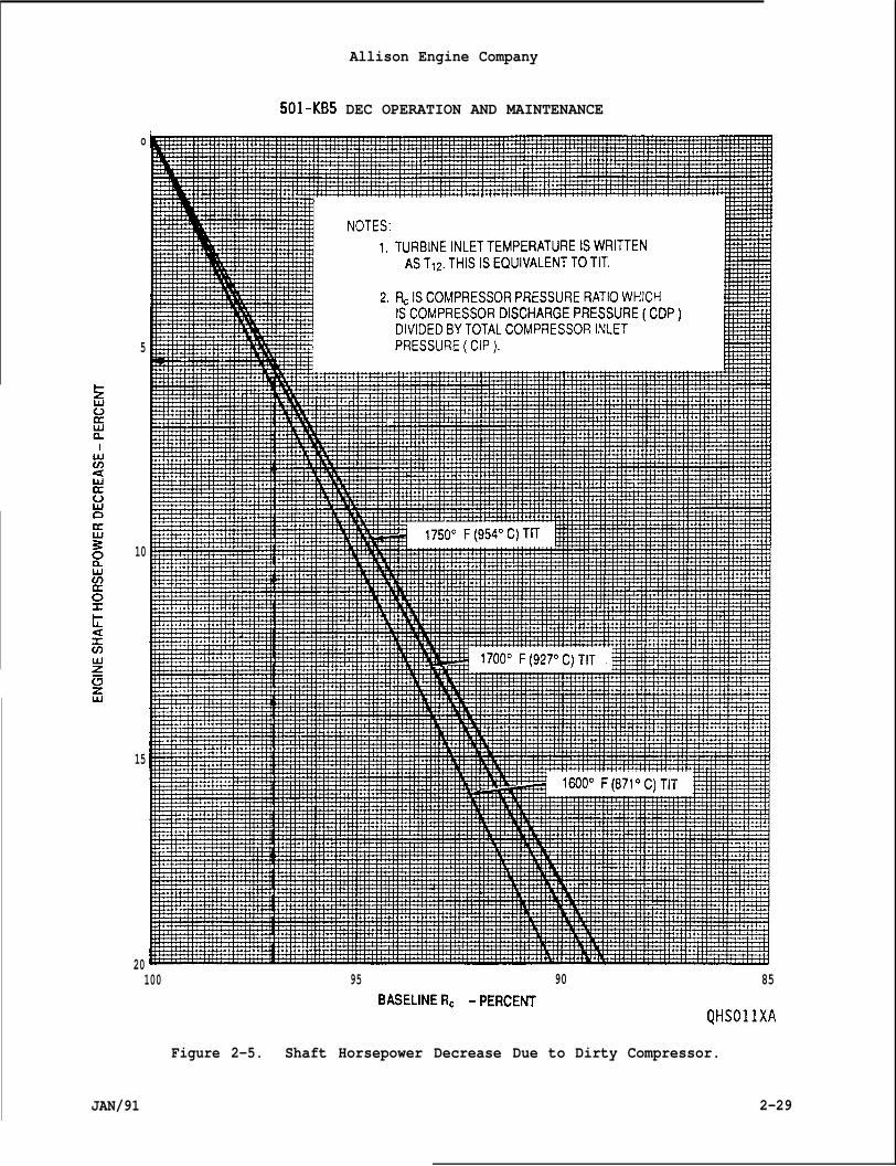
Allison Engine Company
501-KB5 DEC OPERATION AND MAINTENANCE
o
5
10
15
20100 95
BASELINERC -pERcE~
Figure 2-5. Shaft Horsepower Decrease Due
90 85
QHSO1lXA
to Dirty Compressor.
JAN/91 2-29

501-KB5 DEC OPERATION AND MAINTENANCE
Allison Engine Company
Table 2-4. START, RUN , AND STOP REPORT.
Report No.
PLACE:
START, RUN, AND STOP REPORT
Date
CountryLocation No. Name
Other Location Ident.Owner/OperatorReport Recorded byMisc. Ident. Info.
Gas Turbine Engine Model - 501-KB5 DEC ALLISON ASP NO.Driven Equipment Model S/N
START :
Take fuel sample and record condition, as required.
Fuel Lower Heating Valve (LHV)If applicable, prestart check list numberRecord kind of instrumentation if different or unusual from normal, such as,Start-Run Monitoring Test Set.
Check
NOTE: This report assumes that prestart checks and startup and adjustmentruns have been done. If a separate record is not required, thenthis information should be put here in this report.
and Record the Following: Starting Time: (2200 rpm to 3,000 rpm)Compressor Inlet Temperature (CIT): “F ( ‘c)Outside Air Temperature (OAT): “F ( “c)Fuel Supply Pressure: psig (kPag)Minimum Fuel Flow Manifold Pressure: ps:: ( kPag )Ignition RPM: Initial CTIT: ( “c)Peak light-off Calculate Turbine Inlet Temperature (CTIT) “F
I Or\
JAN/91
Acceleration Time (start-to-crank to lightoff) (to 1~,000 rpm) ‘)
2-30
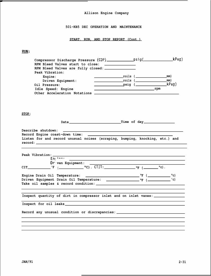
Allison Engine Company
501-KB5 DEC OPERATION AND MAINTENANCE
START. RUN, AND STOP REPORT (Cont.)
JllJJ/:
Compressor Discharge Pressure (CDP) psig( kPag)RPM Bleed Valves start to close:RPM Bleed Valves are fully closed:Peak Vibration:
Engine: roils ( mm)Driven Equipment: roils ( mm)
Oil Pressure: psig ( kPag)Idle Speed: Engine rpmOther Acceleration Notations
STOP:
Date Time of day
Describe shutdown:Record Engine coast-down time:Listen for and record unusual noises (scraping, bumping, knocking, etc.) andrecord:
Peak Vibration:EnfDr
CIT ‘F
Engine Drain OilDriven EquipmentTake oil samples
<*F..
ven Equipment:( “C). CTIT: “F ( “c).
Temperature: “F ( “c)Drain Oil Temperature: “F ( ‘c)& record condition:
Inspect quantity of dirt in compressor inlet and on inlet vanes:
Inspect for oil leaks
Record any unusual condition or discrepancies:
JAN/91 2-31
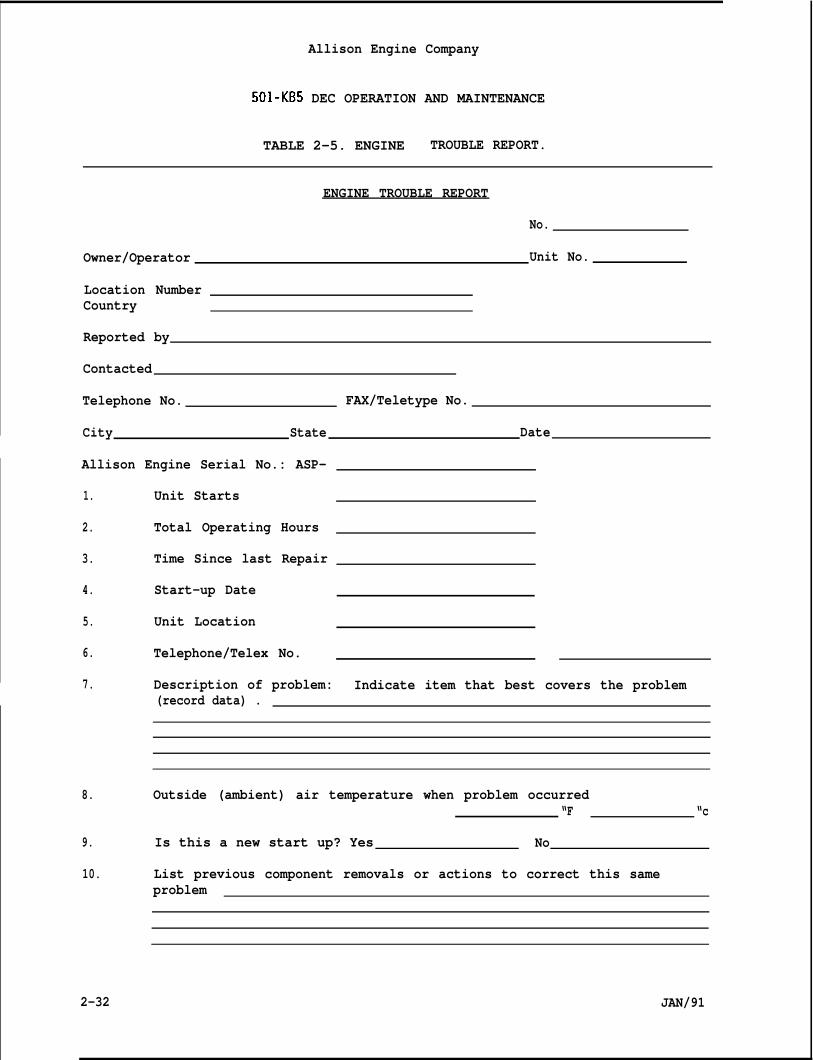
Allison Engine Company
501-KB5 DEC OPERATION AND MAINTENANCE
TABLE 2-5. ENGINE TROUBLE REPORT.
ENGINE TROUBLE REPORT
No.
Owner/Operator Unit No.
Location NumberCountry
Reported by
Contacted
Telephone No. FAX/Teletype No.
City State Date
Allison Engine Serial No.: ASP-
1.
2.
3.
4.
5.
6.
7.
8.
9.
10.
Unit Starts
Total Operating Hours
Time Since last Repair
Start-up Date
Unit Location
Telephone/Telex No.
Description of problem: Indicate item that best covers the problem(record data) .
Outside (ambient) air temperature when problem occurred“F “c
Is this a new start up? Yes No
List previous component removals or actions to correct this sameproblem
2-32 JAN/91
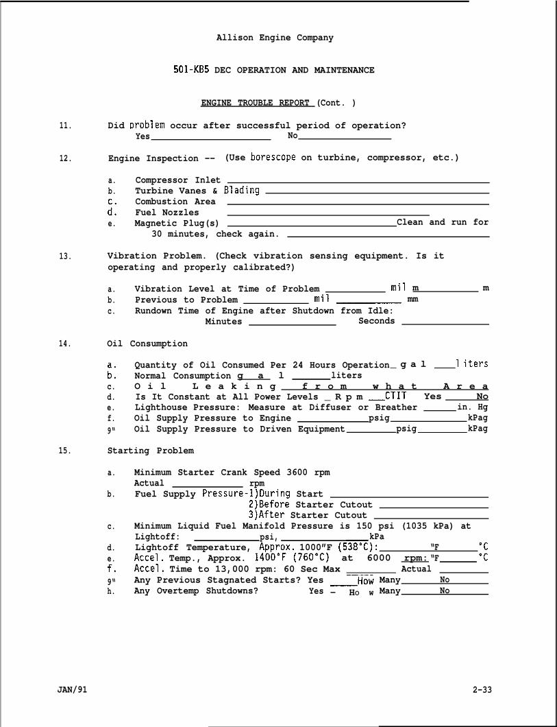
Allison Engine Company
501-KB5 DEC OPERATION AND MAINTENANCE
ENGINE TROUBLE REPORT (Cont. )
11.
12.
13.
14.
15.
a.
b.
c.
d.e.f.9“h.
JAN/91
Did t)roblem occur after successful period of operation?Yes No
Engine Inspection -- (Use borescope on turbine, compressor, etc.)
a. Compressor Inletb. Turbine Vanes & Blading
Combustion Area:: Fuel Nozzlese. Magnetic Plug(s) Clean and run for
30 minutes, check again.
Vibration Problem. (Check vibration sensing equipment. Is itoperating and properly calibrated?)
a. Vibration Level at Time of Problem mil m mb. Previous to Problem mil mmc. Rundown Time of Engine after Shutdown from Idle:
Minutes Seconds
Oil Consumption
Quantity of Oil Consumed Per 24 Hours Operation_ g a l _l iters:: Normal Consumption g a l litersc. O i l L e a k i n g f r o m w h a t A r e ad. Is It Constant at All Power Levels _ R p m _CTIT Yes Noe. Lighthouse Pressure: Measure at Diffuser or Breather in. Hgf. Oil Supply Pressure to Engine psig kPag9“ Oil Supply Pressure to Driven Equipment psig kPag
Starting Problem
Minimum Starter Crank Speed 3600 rpmActual rpmFuel Supply Pressure-l)During Start
2)Before Starter Cutout3)After Starter Cutout
Minimum Liquid Fuel Manifold Pressure is 150 psi (1035 kPa) atLightoff: psi, kPaLightoff Temperature, Approx, 1000”F (538”C): “FAccel, Temp., Approx. 1400”F (760”C) at 6000 rpm: “F ~:Accel. Time to 13,000 rpm: 60 Sec Max ActualAny Previous Stagnated Starts? Yes —HowAny Overtemp Shutdowns? Yes — HO W
Many NoMany No
2-33
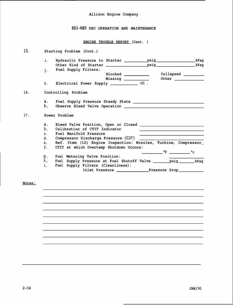
15.
16.
17.
Allison Engine Company
501-KB5 DEC OPERATION AND MAINTENANCE
ENGINE TROUBLE REPORT (Cent. )
Starting Problem (Cont.)
i. Hydraulic Pressure toOther Kind of Starter
j. Fuel Supply Filters:
Starter psig kPagpsig kPag
Blocked CollapsedMissing Other
k. Electrical Power Supply vdc .
Controlling Problem
Fuel Supply Pressure Steady State;: Observe Bleed Valve Operation
Power Problem
Bleed Valve Position, Open or Closed;: Calibration of CTIT Indicatorc. Fuel Manifold Pressure
f. CTIT
:. Fuel. Fuel
i. Fuel
d. Compressor Discharge Pressure (CDP)e. Ref. Item (12) Engine Inspection: Nozzles, Turbine, Compressor_
at which Overtemp Shutdown Occurs:“F “c
Metering Valve Position:Supply Pressure at Fuel Shutoff Valve psig kPagSupply Filters (Cleanliness):
Inlet Pressure Pressure Drop
Notes:
2-34 JAN/91
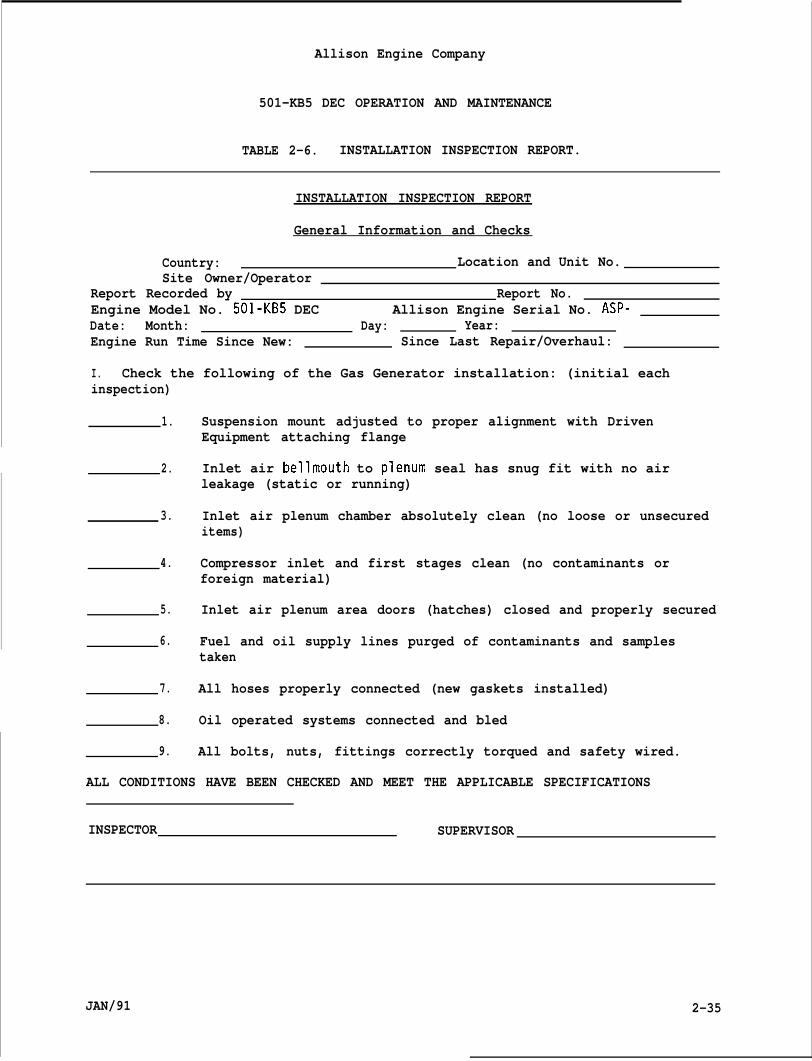
Allison Engine Company
501-KB5 DEC OPERATION AND MAINTENANCE
TABLE 2-6. INSTALLATION INSPECTION REPORT.
INSTALLATION INSPECTION REPORT
General Information and Checks
Country: Location and Unit No.Site Owner/Operator
Report Recorded by Report No.Engine Model No. 501-KB5 DEC Allison Engine Serial No. ASP-Date: Month: Day: Year:Engine Run Time Since New: Since Last Repair/Overhaul:
I. Check the following of the Gas Generator installation: (initial eachinspection)
1.
2.
3.
4.
5.
6.
7.
8.
9.
Suspension mount adjusted to proper alignment with DrivenEquipment attaching flange
Inlet air bellmouth to plenum seal has snug fit with no airleakage (static or running)
Inlet air plenum chamber absolutely clean (no loose or unsecureditems)
Compressor inlet and first stages clean (no contaminants orforeign material)
Inlet air plenum area doors (hatches) closed and properly secured
Fuel and oil supply lines purged of contaminants and samplestaken
All hoses properly connected (new gaskets installed)
Oil operated systems connected and bled
All bolts, nuts, fittings correctly torqued and safety wired.
ALL CONDITIONS HAVE BEEN CHECKED AND MEET THE APPLICABLE SPECIFICATIONS
INSPECTOR SUPERVISOR
JAN/91 2-35
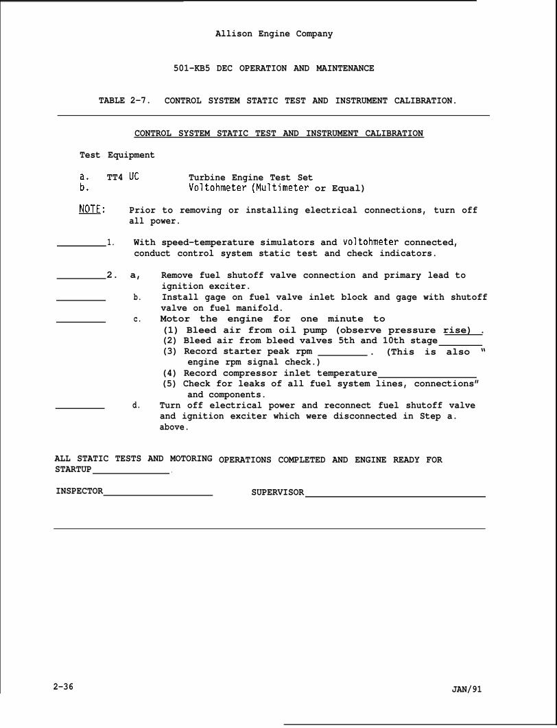
Allison Engine Company
501-KB5 DEC OPERATION AND MAINTENANCE
TABLE 2-7. CONTROL SYSTEM STATIC TEST AND INSTRUMENT CALIBRATION.
CONTROL SYSTEM STATIC TEST AND INSTRUMENT CALIBRATION
Test Equipment
TT4 Uc Turbine Engine Test Set;: Voltohmeter (Multimeter or Equal)
~: Prior to removing or installing electrical connections, turn offall power.
1. With speed-temperature simulators and voltohmeter connected,conduct control system static test and check indicators.
2. a,
b.
c.
d.
Remove fuel shutoff valve connection and primary lead toignition exciter.Install gage on fuel valve inlet block and gage with shutoffvalve on fuel manifold.Motor the engine for one minute to(1) Bleed air from oil pump (observe pressure rise) .(2) Bleed air from bleed valves 5th and 10th stage(3) Record starter peak rpm . (This is also “
engine rpm signal check.)(4) Record compressor inlet temperature(5) Check for leaks of all fuel system lines, connections”
and components.Turn off electrical power and reconnect fuel shutoff valveand ignition exciter which were disconnected in Step a.above.
ALL STATIC TESTS AND MOTORINGSTARTUP .
INSPECTOR
OPERATIONS COMPLETED AND ENGINE READY FOR
SUPERVISOR
2-36 JAN/91

Allison Engine Company
501-KB5 DEC OPERATION AND MAINTENANCE
TABLE 2-8. START-UP AND ADJUSTMENT RUNS
1.
2.
3.
START-UP AND ADJUSTMENT RUNS
Inspect fuel shutoff valve and ignition control circuit forcorrect connection.
Make first start and monitor and record:
a. Lightoff rpm .b. Lightoff peak CTITc. Minimum fuel manifold pressure (If ~sed, close gage shutoff
valve before pressure exceeds gage limit).d. Acceleration rate and temperature characteristics. (Time “
lapse from lightoff to idle setting) .
a. Record the following final settings.
(1) Compressor Inlet Temperature (CIT)(2) Fuel Pressure
.
(3) Lightoff Turbine Temperature.
(4) Acceleration Time (Lightoff to 13,000 rpm) .
b. During rpm increase from 13,000 rpm, monitor bleed valveclosing operation for rpm range of open to 100% closedversus compressor inlet temperature. Compare data toCIT-to-RPM graph.
ENGINE INSTALLATION, STATIC CHECKS AND OPERATIONAL ADJUSTMENTS ARE WITHINSPECIFICATIONS. UNIT IS READY FOR SERVICE.
INSPECTOR SUPERVISOR
JAN/91 2-37
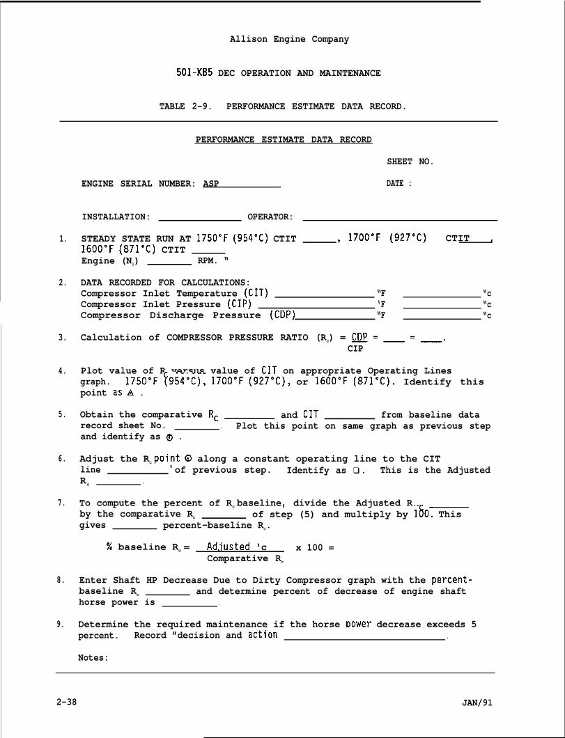
Allison Engine Company
501-KB5 DEC OPERATION AND MAINTENANCE
TABLE 2-9. PERFORMANCE ESTIMATE DATA RECORD.
1.
2.
3.
4.
5.
6.
7.
8.
9.
ENGINE SERIAL
INSTALLATION:
PERFORMANCE ESTIMATE DATA RECORD
SHEET NO.
NUMBER: ASP DATE :
OPERATOR:
STEADY STATE RUN AT 1750”F (954°C) CTIT * 1700”F (927”C) CTIT ,1600”F (871”C) CTITEngine (Nl) RPM. “
DATA RECORDED FOR CALCULATIONS:Compressor Inlet Temperature (CIT) “F “cCompressor Inlet Pressure (CIP) ‘F “cCompressor Discharge Pressure (CDP) “F “c
Calculation of COMPRESSOR PRESSURE RATIO (Rc) = ~=_=_.CIP
Plot value of R versus value of CIT on appropriate Operating Linesgraph. 1750”F ~954°C), 1700”F (927”C), or 1600”F (871”C). Identify thispoint as A .
Obtain the comparative Rc and CIT from baseline datarecord sheet No. . Plot this point on same graph as previous stepand identify as ~ .
Adjust the Rc pointo along a constant operating line to the CITline 0 of previous step. Identify as ❑ . This is the AdjustedRc .
To compute the percent of Rc baseline, divide the Adjusted Rby the comparative Rc of step (5) and multiply by lbO. Thisgives percent-baseline Rc.
% baseline Rc = Ad.iusted ‘c x 100 =Comparative Rc
Enter Shaft HP Decrease Due to Dirty Compressor graph with the percent-baseline Rc and determine percent of decrease of engine shafthorse power is .
Determine the required maintenance if the horse Dower decrease exceeds 5percent. Record ”decision and tiction .
Notes:
2-38 JAN/91
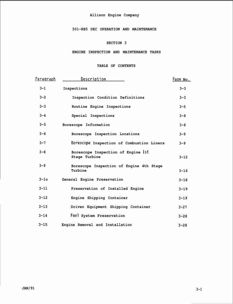
Paraqra~h
3-1
3-2
3-3
3-4
3-5
3-6
3-7
3-8
3-9
3-1o
3-11
3-12
3-13
3-14
3-15
Allison Engine Company
501-KB5 DEC OPERATION AND MAINTENANCE
SECTION 3
ENGINE INSPECTION AND MAINTENANCE
TABLE OF CONTENTS
Descri~tion
Inspections
Inspection Condition Definitions
Routine Engine Inspections
Special Inspections
Borescope Information
Borescope Inspection Locations
TASKS
Borescope Inspection of Combustion Liners
Borescope Inspection of Engine 1stStage Turbine
Borescope Inspection of Engine 4th StageTurbine
General Engine Preservation
Preservation of Installed Engine
Engine Shipping Container
Driven Equipment Shipping Container
Fuel System Preservation
Engine Removal and Installation
Paqe No.
3-3
3-3
3-5
3-8
3-8
3-9
3-9
3-12
3-16
3-18
3-19
3-19
3-27
3-28
3-28
JAN/91 3-1
Fiaure No.
3-1
3-2
3-3
3-4
3-5
3-6
3-7
3-8
Table No.
3-1
3-2
.
Allison Engine Company
501-KB5 DEC OPERATION AND MAINTENANCE
INDEX TO FIGURES
Borescope Inspection of Combustion Liner
Unacceptable (Not Allowed) Sulfidation ofTurbine Blades and Vanes Examples
1st Stage Vane Airfoil Leading EdgeDamage Examples
Unacceptable (Not Allowed) 1st StageVane Damage Examples
Acceptable (Allowed) 1st Stage VaneDamage Examples
4th Stage Vane Burn Through Example
4th Stage Vane with Unacceptable (NotAllowed) Peripheral Cracking Example
Engine Shipping Container
INDEX TO TABLES
Title
Inspection Tasks
Engine Shipping Container Air PressureRequirements Versus Temperature
Paqe No.
3-11
3-13
3-14
3-14
3-15
3-17
3-17
3-23
Paae No.
3-6
3-27
3-2 JAN/91
Allison Engine Company
501-KB5 DEC OPERATION AND
SECTION 3
MAINTENANCE
ENGINE INSPECTION AND MAINTENANCE TASKS
3-1. INSPECTIONS.
3-2. INSPECTION CONDITION DEFINITIONS.
JAN/91
il.
B.
c.
D.
E.
F.
G.
H.
I.
J.
K.
Abrasion - An area of roughened scratches or marks, usually causedby foreign matter between moving parts or surfaces.
Blistering - Raised areas indicating separation of the surface fromthe base. Usually found on plated or painted surfaces. Associatedwith flaking or peeling. The usual cause is the imperfect bond withthe base aggravated by the presence of moisture, gas, heat, orpressure.
Brinelling - One or more indentations on bearing ring races,usually caused by high static loads or application of force duringinstallation and/or removal. Indentations are rounded and/orspherical due to the impression left by the contacting balls and/orrollers of the bearing.
Burning - Surface damage due to excessive heat, usually caused byimproper fit, defective lubrication, or overtemperature operation.
Burnishing - Mechanical smoothing of a metal surface by rubbing.Not accompanied by removal of material but sometimes by discolorationaround the outer edges of the area. Operational burnishing is notdetrimental if it covers approximately the area carrying the load,and provided there is not evidence of pileup or burning. The usualcause is the normal operation of the parts.
Burr - A sharp or roughened projection of metal, usually a resultof machine processing.
Chafing - Should be used to describe the cause for other definedsurface conditions rather than a description of the actualcondition. (same as Fretting. )
Chipping - The breaking away of pieces of material, usually causedby excessive stress concentration or careless handling.
Corrosion - Surface damage caused by chemical action.
Crack - A partial separation of material, usually caused by vibra-tion, overloading, faulty internal stresses, defective assembly, orfatigue.
Crazing - A surface coating condition which may appear incombination with grain boundary oxidation or other base metal attackconditions. In appearance it will often be evident in parches and
3-3
L.
M.
N.
o.
P.
Q.
R.
s.
T.
3-4
Allison Engine Company
501 -KB5 DEC OPERATION AND MAINTENANCE
craze lines. Craze lines will not necessarily follow graboundaries but often tend toward symmetry.
n
Dent - A small, rounded depression in a surface, usually caused bythe part being struck with a rounded object.
Erosion - The removal of metal by the high velocity gases usuallyin the combustion liners and turbine unit components.
Fatigue Failure - Progressive yielding of one or more local areasof weakness such as tool marks, sharp indentations, minute cracks, orinclusions under repeated stress. As the working stress on the pieceis repeated, cracks develop at the ends, where high concentrations ofstress exist. The cracks spread usually from the surface or near thesurface of the area. After a time, there is so little sound metalleft the normal stress of the piece is higher than the strength ofthe remaining material, and it snaps. Failure is not due tocrystallization of metal as many mechanics believe. The appearanceof a typical fatigue failure is easily explained. As failureproceeds, the severed surfaces rub and batter each other, crushingthe grains of the material and producing the dull or smoothappearance; the remaining unfractured portion preserves the normalgrain structure up to the moment of failure. The progressive natureof the failure is usually indicated by several more or lessconcentric lines, the center or focus of which discloses the originalpoint or line of failure. The usual causes are tool marks, sharpcorners, nicks, cracks, inclusions, galling, corrosion, orinsufficient tightening of studs or bolts to obtain proper stretch.
Flaking - The breaking loose of small pieces of metal or coatedsurfaces, usually caused by defective plating or excessive loading.
Fretting - (See definition for Chafing. )
Galling - A severe condition of Chafing or Fretting in which atransfer of metal from one part to another occurs, usually caused bya slight movement of mated parts having limited relative motion andunder high loads.
Gouging - A furrowing condition in which a displacement of metalhas occurred (a torn effect), usually caused by a relatively largepiece of metal or foreign material between close moving parts.
Grain Boundary Oxidation - A pattern following boundaries of metalgrain resultinq from removed surface oxides. The more Drominent areais usually in the form
Grooving - A recess orUsually caused by cont.parts.
of stringers.
channel with rounded and smoothed edges.nued abnormal wear or faulty alignment of
JAN/91
u.
v.
w.
x.
Y.
z.
AA.
AB .
AC.
AD.
Allison Engine Company
!) U1-KB5 UEC
Inclusion - A particlewith magnetic particle
OPERATION AND MAINTENANCE
of foreign matter in the metal, associatedinspection.
Nick - A sharp sided gouge or depression with a V-shaped bottom,usually a result of careless handling of tools and parts.
Peening - A series of blunt depressions in a surface, such as froma hammer.
Pickup - A buildup or rolling of metal from one area to another,usually caused by insufficient lubrication, clearances, or foreignmatter. (See Scuff ing. )
Pitting - Small hollows or irregular shape in the surface, usuallycaused by corrosion or minute mechanical chipping of surfaces.
Scoring - A series of deep scratches, usually caused by foreignparticles between moving parts or careless assembly or disassemblytechniques.
Scratches - Shallow, thin lines or marks, varying in degree, causedby presence of fine particles during operation or contact with otherparts during handling.
Scuffing - A surface condition evidenced by pickup, usually causedby insufficient clearance or lubrication.
Spalling - A roughened area indicated by a chipping or peeling ofthe surface metal, usually caused by any surface damage under load.(Do not misinterpret as Flaking. )
Electrical Discharge Damage - Pitting as a result of localizedoverheating of material at the moment of electrical arcing ordischarge. The center of the pit consists of a white, hard, brittlesubstance surrounded bv a rim of liqht brown (straw) color. In somecases, the hard center bf the pit ma~ have separated’and be missing.
es are provided
3-3. ROUTINE ENGINE INSPECTIONS.
A. The basic engine inspections and inspection frequent(Ref. Table 3-1).
B. There is a great difference in engine operating conditions, thereforethe operator should develop and refine inspection criteria andfrequencies that will best suit the specific conditions of theirengine operating conditions, within the applicable regulatoryagencies that will establish certain inspections and inspectionintervals.
JAN/91 3-5
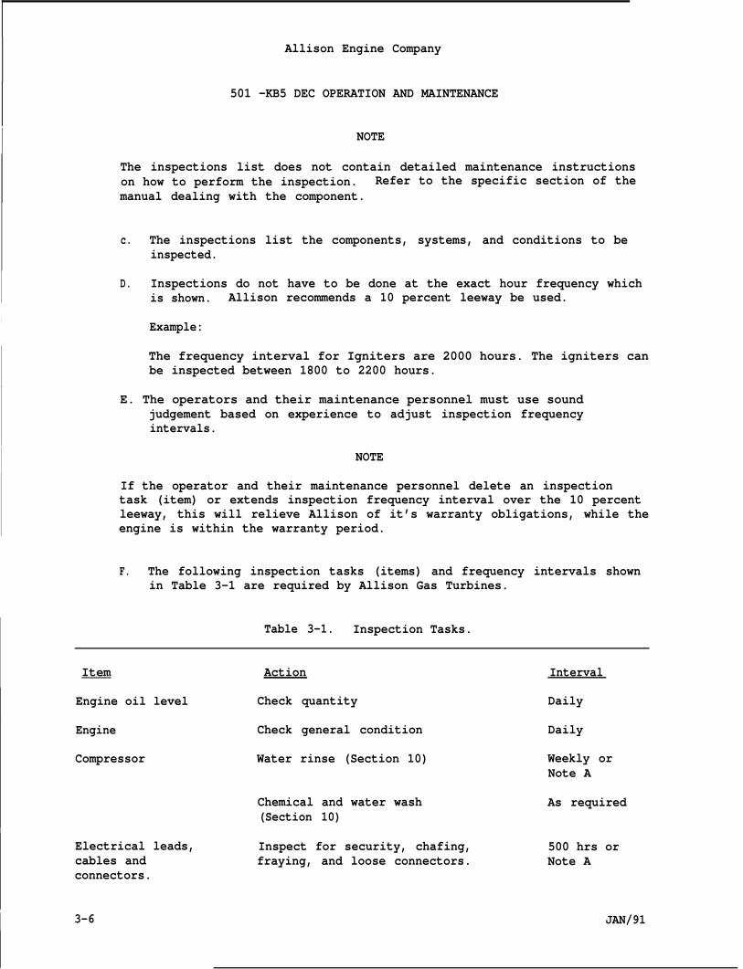
Allison Engine Company
501 -KB5 DEC OPERATION AND MAINTENANCE
I NOTE
The inspections list does not contain detailed maintenance instructionson how to perform the inspection. Refer to the specific section of themanual dealing with the component.
c. The inspections list the components, systems, and conditions to beinspected.
D. Inspections do not have to be done at the exact hour frequency whichis shown. Allison recommends a 10 percent leeway be used.
I Example:
The frequency interval for Igniters are 2000 hours. The igniters canbe inspected between 1800 to 2200 hours.
E. The operators and their maintenance personnel must use soundjudgement based on experience to adjust inspection frequencyintervals.
I NOTE
If the operator and their maintenance personnel delete an inspectiontask (item) or extends inspection frequency interval over the 10 percentleeway, this will relieve Allison of it’s warranty obligations, while theengine is within the warranty period.
F. The following inspection tasks (items) and frequency intervals shownin Table 3-1 are required by Allison Gas Turbines.
Table 3-1. Inspection Tasks.
Item Action Interval
Engine oil level Check quantity Daily
Engine Check general condition Daily
Compressor Water rinse (Section 10) Weekly orNote A
Chemical and water wash As required(Section 10)
I
Electrical leads, Inspect for security, chafing, 500 hrs orcables and fraying, and loose connectors. Note Aconnectors.
I 3-6 JAN/91
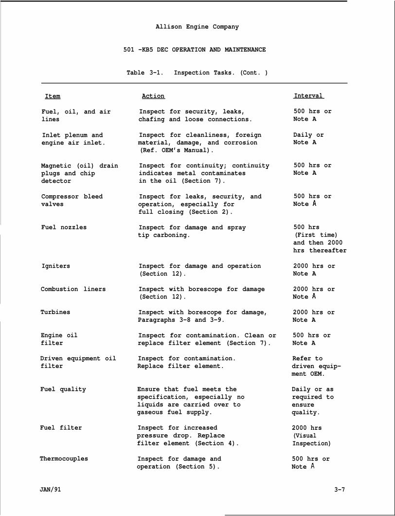
Allison Engine Company
501 -KB5 DEC OPERATION AND MAINTENANCE
Table 3-1. Inspection Tasks. (Cont. )
Item
Fuel, oil, and airlines
Inlet plenum andengine air inlet.
Magnetic (oil) drainplugs and chipdetector
Compressor bleedvalves
Fuel nozzles
Igniters
Combustion liners
Turbines
Engine oilfilter
Driven equipment oilfilter
Fuel quality
Fuel filter
Thermocouples
JAN/91
Action
Inspect for security, leaks,chafing and loose connections.
Inspect for cleanliness, foreignmaterial, damage, and corrosion(Ref. OEM’s Manual).
Inspect for continuity; continuityindicates metal contaminatesin the oil (Section 7).
Inspect for leaks, security, andoperation, especially forfull closing (Section 2).
Inspect for damage and spraytip carboning.
Inspect for damage and operation(Section 12).
Inspect with borescope for damage(Section 12).
Inspect with borescope for damage,Paragraphs 3-8 and 3-9.
Inspect for contamination. Clean orreplace filter element (Section 7).
Inspect for contamination.Replace filter element.
Ensure that fuel meets thespecification, especially noliquids are carried over togaseous fuel supply.
Inspect for increasedpressure drop. Replacefilter element (Section 4).
Inspect for damage andoperation (Section 5).
Interval
500 hrs orNote A
Daily orNote A
500 hrs orNote A
500 hrs orNote A
500 hrs(First time)and then 2000hrs thereafter
2000 hrs orNote A
2000 hrs orNote A
2000 hrs orNote A
500 hrs orNote A
Refer todriven equip-ment OEM.
Daily or asrequired toensurequality.
2000 hrs(VisualInspection)
500 hrs orNote A
3-7
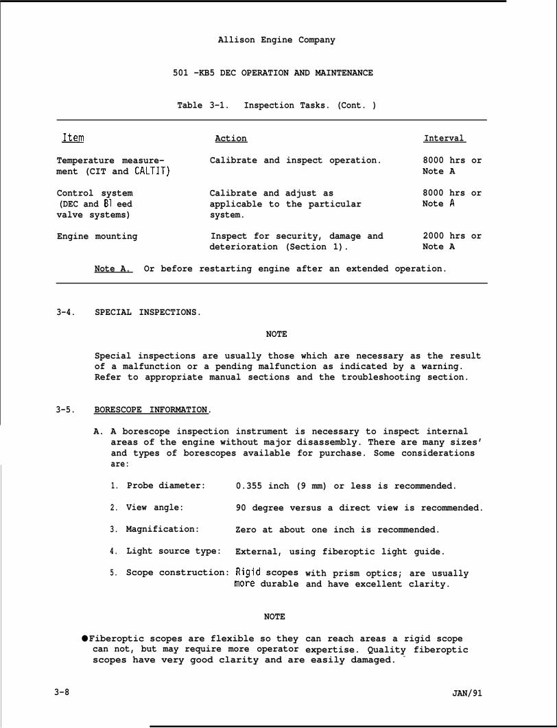
Allison Engine Company
501 -KB5 DEC OPERATION AND MAINTENANCE
Table 3-1. Inspection Tasks. (Cont. )
~ Action Interval
Temperature measure- Calibrate and inspect operation. 8000 hrs orment (CIT and CALTIT) Note A
Control system Calibrate and adjust as 8000 hrs or(DEC and B1 eed applicable to the particular Note Avalve systems) system.
Engine mounting Inspect for security, damage and 2000 hrs ordeterioration (Section 1). Note A
Note A. Or before restarting engine after an extended operation.
3-4. SPECIAL INSPECTIONS.
NOTE
Special inspections are usually those which are necessary as the resultof a malfunction or a pending malfunction as indicated by a warning.Refer to appropriate manual sections and the troubleshooting section.
3-5. BORESCOPE INFORMATION.
A. A borescope inspection instrument is necessary to inspect internalareas of the engine without major disassembly. There are many sizes’and types of borescopes available for purchase. Some considerationsare:
1.
2.
3.
4.
5.
Probe diameter: 0.355 inch (9 mm) or less is recommended.
View angle: 90 degree versus a direct view is recommended.
Magnification: Zero at about one inch is recommended.
Light source type: External, using fiberoptic light guide.
Scope construction: Rigid scopesmo~e durable
NOTE
● Fiberoptic scopes are flexible so theycan not, but may require more operator
with prism optics; are usuallyand have excellent clarity.
can reach areas a rigid scopeexpertise. Quality fiberoptic
scopes have very good clarity and are easily damaged. -
3-8 JAN/91
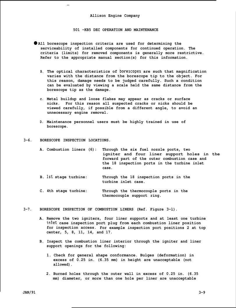
—
Allison Engine Company
501 -KB5 DEC OPERATION AND MAINTENANCE
● A1l borescope inspection criteria are used for determining theserviceability of installed components for continued operation. Thecriteria (limits) for removed components is generally more restrictive.Refer to the appropriate manual section(s) for this information.
B.
c.
D.
The optical characteristics of borescopes are such that magnificationvaries with the distance from the borescope tip to the object. Forthis reason, damage needs to be judged carefully. Such a conditioncan be evaluated by viewing a scale held the same distance from theborescope tip as the damage.
Metal buildup and loose flakes may appear as cracks or surfacenicks. For this reason all suspected cracks or nicks should beviewed carefully, if possible from a different angle, to avoid anunnecessary engine removal.
Maintenance personnel users must be highly trained in use ofborescope.
3-6. BORESCOPE INSPECTION LOCATIONS.
A. Combustion liners (6): Through the six fuel nozzle ports, twoigniter and four liner support holes in theforward part of the outer combustion case andthe 18 inspection ports in the turbine inletcase.
B. 1st stage turbine: Through the 18 inspection ports in theturbine inlet case.
C. 4th stage turbine: Through the thermocouple ports in thethermocouple support ring.
3-7. BORESCOPE INSPECTION OF COMBUSTION LINERS (Ref. Figure 3-l).
A. Remove the two igniters, four liner supports and at least one turbineinlet case inspection port plug from each combustion liner positionfor inspection access. For example inspection port positions 2 at topcenter, 5, 8, 11, 14, and 17.
B. Inspect the combustion liner interior through the igniter and linersupport openings for the following:
1. Check for general shape conformance. Bulges (deformation) inexcess of 0.25 in. (6.35 mm) in height are unacceptable (notallowed).
2. Burned holes through the outer wall in excess of 0.25 in. (6.35mm) diameter, or more than one hole per liner are unacceptable
JAN/91 3-9
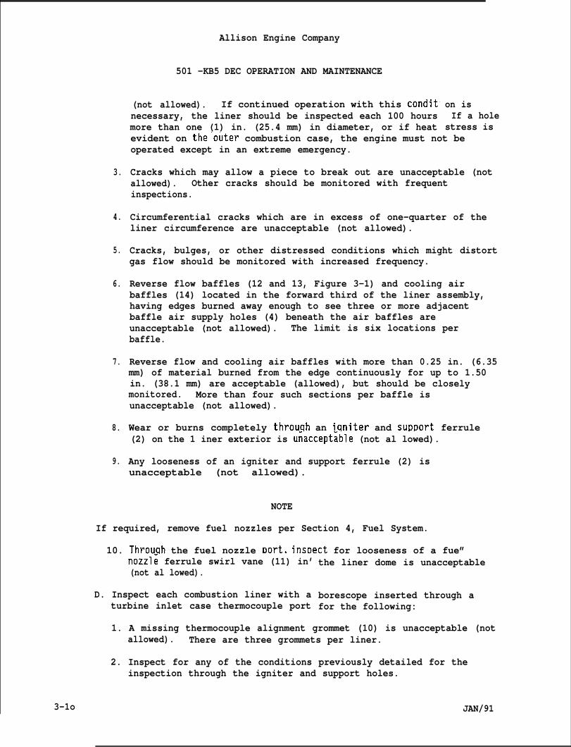
Allison Engine Company
3.
4.
5.
6.
7.
8.
9.
501 -KB5 DEC OPERATION AND MAINTENANCE
(not allowed). If continued operation with this conditnecessary, the liner should be inspected each 100 hoursmore than one (1) in. (25.4 mm) in diameter, or if heat
on isIf a hole
stress isevident on the”outer combustion case, the engine must not beoperated except in an extreme emergency.
Cracks which may allow a piece to break out are unacceptable (notallowed). Other cracks should be monitored with frequentinspections.
Circumferential cracks which are in excess of one-quarter of theliner circumference are unacceptable (not allowed).
Cracks, bulges, or other distressed conditions which might distortgas flow should be monitored with increased frequency.
Reverse flow baffles (12 and 13, Figure 3-1) and cooling airbaffles (14) located in the forward third of the liner assembly,having edges burned away enough to see three or more adjacentbaffle air supply holes (4) beneath the air baffles areunacceptable (not allowed). The limit is six locations perbaffle.
Reverse flow and cooling air baffles with more than 0.25 in. (6.35mm) of material burned from the edge continuously for up to 1.50in. (38.1 mm) are acceptable (allowed), but should be closelymonitored. More than four such sections per baffle isunacceptable (not allowed).
Wear or burns completely throuqh an iqniter and surmort ferrule(2) on the 1 iner exterior is u~accept~ble (not al lowed).
Any looseness of an igniter and support ferrule (2) isunacceptable (not allowed). ““
NOTE
If required, remove fuel nozzles per Section 4, Fuel System.
10. Throuqh the fuel nozzle Dort. insDect for looseness of a fue”nozzl~ ferrule swirl vane (11) in’(not al lowed).
D. Inspect each combustion liner with aturbine inlet case thermocouple port
the liner dome is unacceptable
borescope inserted through afor the following:
1. A missing thermocouple alignment grommet (10) is unacceptable (notallowed). There are three grommets per liner.
2. Inspect for any of the conditions previously detailed for theinspection through the igniter and support holes.
3-1o JAN/91
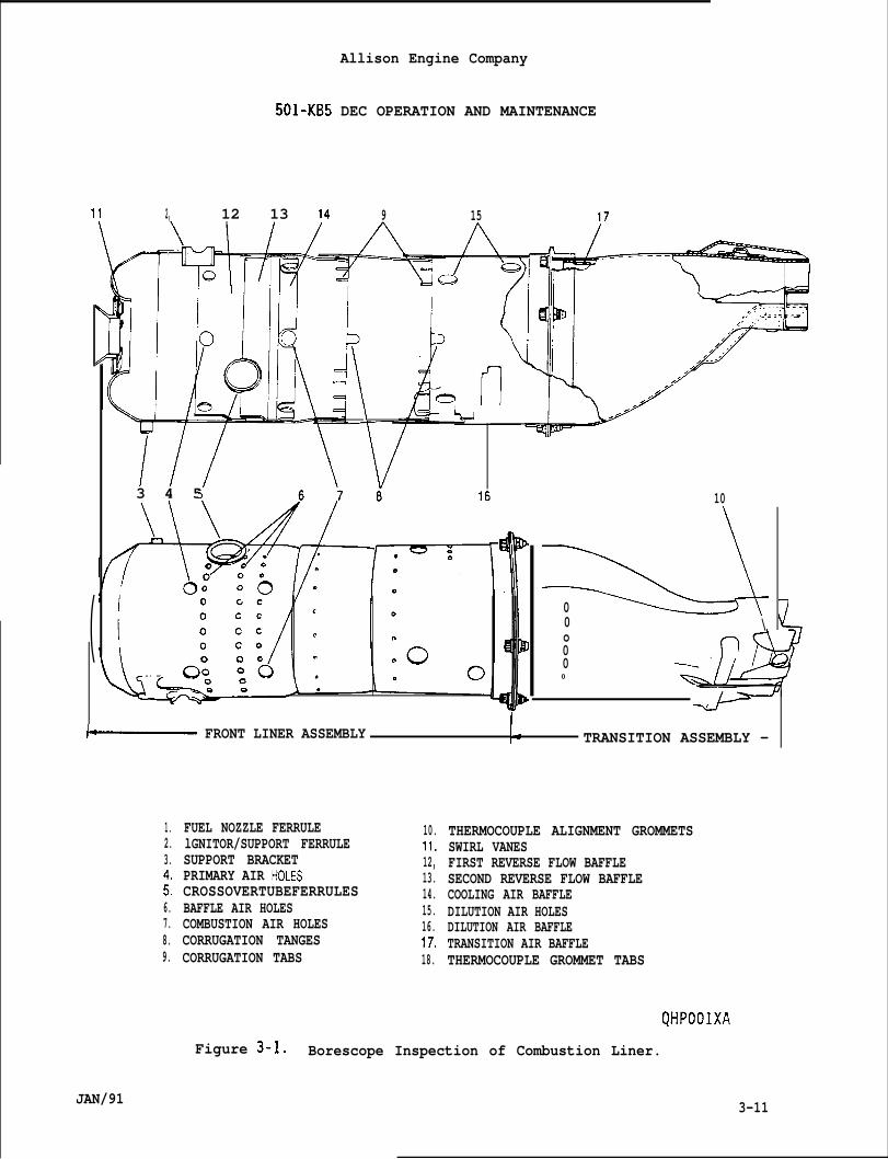
Allison Engine Company
501-KB5 DEC OPERATION AND MAINTENANCE
11 2, 12 13 14 9 15 17
(
////“
\ Q
3 4 5
‘ u:,
10
00 \o000
~ FRONT LINER ASSEMBLY ~: TRANSITION ASSEMBLY —
1.2.3.
$6.7.8.9.
JAN/91
FUEL NOZZLE FERRULElGNITOR/SUPPORT FERRULESUPPORT BRACKETPRIMARY AIR HOLESCROSSOVERTUBEFERRULESBAFFLE AIR HOLESCOMBUSTION AIR HOLESCORRUGATION TANGESCORRUGATION TABS
10.11.12,13.14.15.16.17.18.
THERMOCOUPLE ALIGNMENT GROMMETSSWIRL VANESFIRST REVERSE FLOW BAFFLESECOND REVERSE FLOW BAFFLECOOLING AIR BAFFLEDILUTION AIR HOLESDILUTION AIR BAFFLETRANSITION AIR BAFFLETHERMOCOUPLE GROMMET TABS
QHPOOIXA
Figure 3-1. Borescope Inspection of Combustion Liner.
3-11
Allison Engine Company
●
●
3-8.
3-12
501-KB5 DEC
E. Borescoping combustion
OPERATION AND MAINTENANCE
liners with ceramic coated interiors:
NOTE
There is no limit to the loss of ceramic coating for continued engineoperation. Its purpose is to delay the time at which the combustionliner walls are exposed to the high radiated heat. Inspect thesecombustion liners using the same criteria as non-ceramic coated liners.
Combustion liner damage is often the result of a fuel nozzle problem.Combustion liner damage is accelerated by excessive temperatures as maybe caused by overtemperature operation or poor starting. Reduced fuelflow from one fuel nozzle will cause excess flow from the other fuelnozzles thus creating an overtemperature condition. Liquid carry-overinto the gaseous fuel is a primary cause of combustion liner damage.
BORESCOPE INSPECTION OF ENGINE 1ST STAGE TURBINE.
A. Remove at least one turbine inlet case inspection port plug from eachcombustion liner for inspection access. For example port positions 2at top center, 5, 8, 11, 14 and 17.
B. Inspect the engine 1st stage turbine vanes and as much of the 1ststage rotor blades as are visible with a borescope inserted in theinspection port. If any damage is found, a complete inspectionthrough all 18 inspection ports is recommended. See the Figures 3-2through 3-5 for sulfidation and cracking damage examples.
C. Inspect vanes for evidence of sulfidation. Sulfidation is a form ofhot corrosion that progresses from a rough or crusty appearance,usually greenish black in color, to a condition that separates themetal grain boundaries into layers. The 1st stage vane leading edgesare most subject to this damage. Sulfidation that severely affectsthe airfoil contour or causes a badly delaminated appearance isunacceptable (not allowed).
NOTE
The 1st stage vane cracks usually occur due to thermal shock, such asoccurs during poor (hot) starts or from fuel nozzle problems or from theeffects of water rinsing and washing when the turbine residualtemperature is more than 250”F (121”C).
D. Inspect vanes for evidence of cracks. Cracks more than 0.375 (3/8)inch (9.53 mm) long are unacceptable (not allowed). Any number ofcracks less than 0.375 (3/8) inch (9.53 mm) long are acceptable(allowed) provided they are separated such that piece breakout isunlikely. Cracked vanesshould be monitored with frequentinspections.
JAN/91
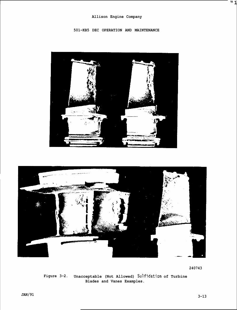
“1
Allison Engine Company
501-KB5 DEC OPERATION AND MAINTENANCE
Figure 3-2. Unacceptable (Not Allowed) Sulfidation of TurbineBlades and Vanes Examples.
JAN/91
240743
3-13
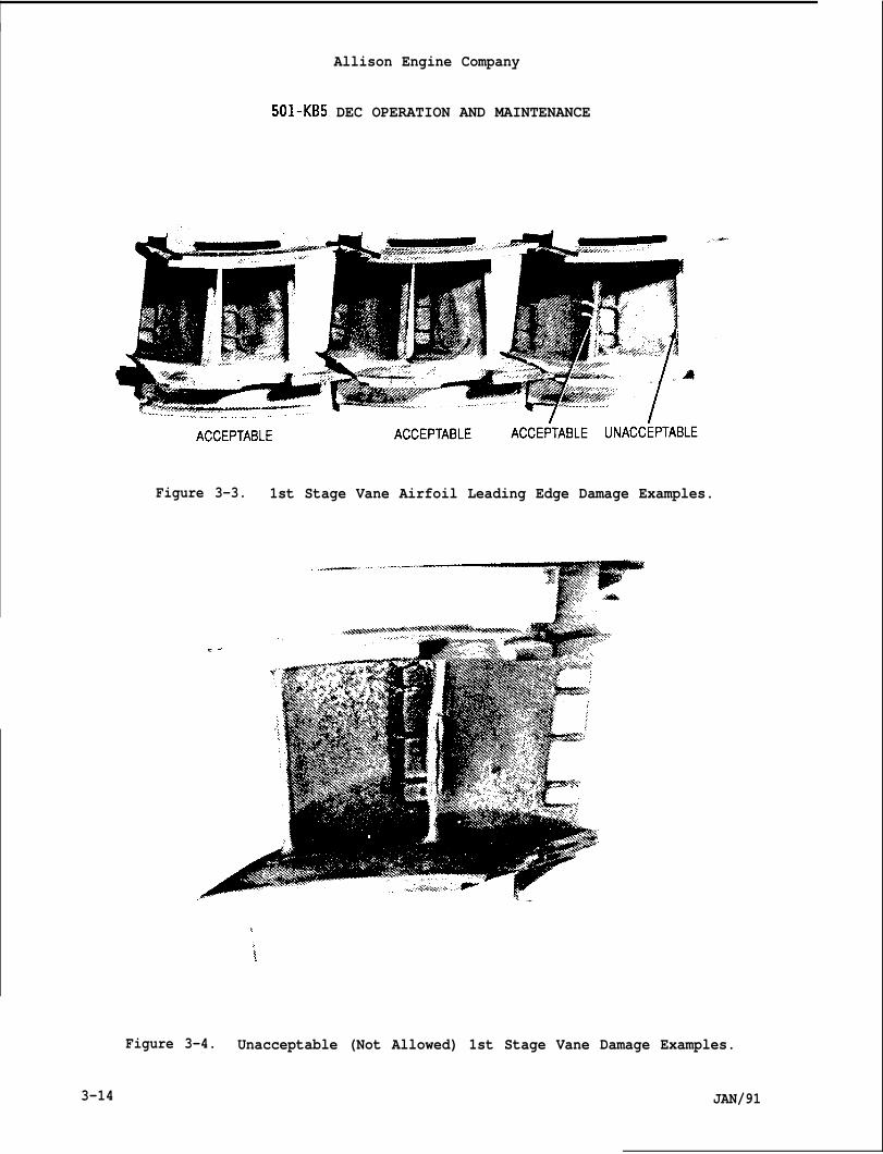
Allison Engine Company
501-KB5 DEC OPERATION AND MAINTENANCE
Figure 3-3.
-., ““.
1st Stage Vane Airfoil Leading Edge Damage Examples.
. ..- .,. ,-,. .’-”---
,
‘i
Figure 3-4. Unacceptable (Not Allowed) 1st Stage Vane Damage Examples.
3-14 JAN/91
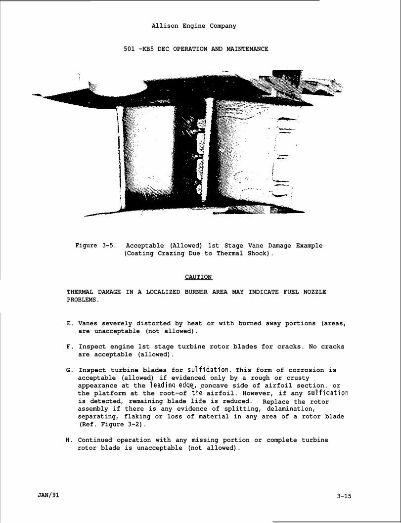
Allison Engine Company
501 -KB5 DEC OPERATION AND MAINTENANCE
-m
Figure 3-5. Acceptable (Allowed) 1st Stage Vane Damage Example(Coating Crazing Due to Thermal Shock).
CAUTION
THERMAL DAMAGE IN A LOCALIZED BURNER AREA MAY INDICATE FUEL NOZZLEPROBLEMS.
E. Vanes severely distorted by heat or with burned away portions (areas,are unacceptable (not allowed).
F. Inspect engine 1st stage turbine rotor blades for cracks. No cracksare acceptable (allowed).
G. Inspect turbine blades for sulfidation. This form of corrosion isacceptable (allowed) if evidenced only by a rough or crustyappearance at the leadinq edqe, concave side of airfoil section. orthe platform at the root-of ~he airfoil. However, if any sulfidationis detected, remaining blade life is reduced. Replace the rotorassembly if there is any evidence of splitting, delamination,separating, flaking or loss of material in any area of a rotor blade(Ref. Figure 3-2).
H. Continued operation with any missing portion or complete turbinerotor blade is unacceptable (not allowed).
JAN/91 3-15
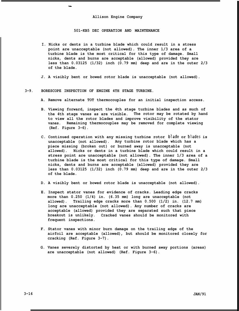
.
Allison Engine Company
3-9.
501-KB5 DEC OPERATION AND MAINTENANCE
I. Nicks or dents in a turbine blade which could result in a stresspoint are unacceptable (not allowed). The inner 1/3 area of aturbine blade is the most critical for this type of damage. Smallnicks, dents and burns are acceptable (allowed) provided they areless than 0.03125 (1/32) inch (0.79 mm) deep and are in the outer 2/3of the blade.
J. A visibly bent or bowed rotor blade is unacceptable (not allowed).
BORESCOPE INSPECTION OF ENGINE 4TH STAGE TURBINE.
A. Remove alternate TOT thermocouples for an initial inspection access.
B. Viewing forward, inspect the 4th stage turbine blades and as much ofthe 4th stage vanes as are visible. The rotor may be rotated by handto view all the rotor blades and improve visibility of the statorvanes. Remaining thermocouples may be removed for complete viewing(Ref. Figure 3-6).
C. Continued operation with any missing turbine rotor .blade or blades isunacceptable (not allowed). Any turbine rotor blade which has apiece missing (broken out) or burned away is unacceptable (notallowed). Nicks or dents in a turbine blade which could result in astress point are unacceptable (not allowed). The inner 1/3 area of aturbine blade is the most critical for this type of damage. Smallnicks, dents and burns are acceptable (allowed) provided they areless than 0.03125 (1/32) inch (0.79 mm) deep and are in the outer 2/3of the blade.
D. A visibly bent or bowed rotor blade is unacceptable (not allowed).
E. Inspect stator vanes for evidence of cracks. Leading edge cracksmore than 0.250 (1/4) in. (6.35 mm) long are unacceptable (notallowed). Trailing edge cracks more than 0.500 (1/2) in. (12.7 mm)long are unacceptable (not allowed). Any number of cracks areacceptable (allowed) provided they are separated such that piecebreakout is unlikely. Cracked vanes should be monitored withfrequent inspections.
F. Stator vanes with minor burn damage on the trailing edge of theairfoil are acceptable (allowed), but should be monitored closely forcracking (Ref. Figure 3-7).
G. Vanes severely distorted by heat or with burned away portions (areas)are unacceptable (not allowed) (Ref. Figure 3-6).
3-16 JAN/91
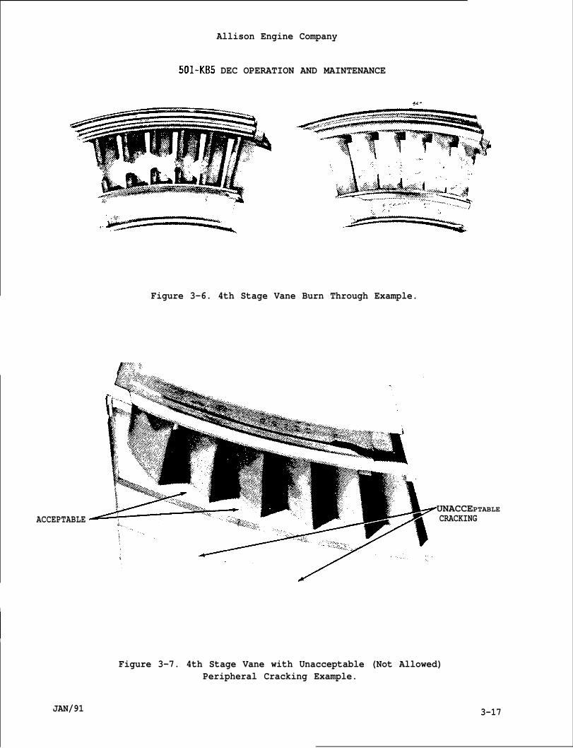
Allison Engine Company
501-KB5 DEC OPERATION AND MAINTENANCE
ACCEPTABLE
I
I
JAN/91
$*-
. .
Figure 3-6. 4th Stage Vane Burn Through Example.
UNACCEPTABLECRACKING
Figure 3-7. 4th Stage Vane with Unacceptable (Not Allowed)Peripheral Cracking Example.
3-17
Allison Engine Company
501-KB5 DEC OPERATION AND MAINTENANCE
CAUTION
IF ANY VANE AIRFOIL IS BURNED COMPLETELY THROUGH AXIALLY, SUCH THAT THECONNECTION BETWEEN THE INNER AND OUTER VANE BAND AT ANY AIRFOIL LOCATIONIS SEVERED, THE FOLLOWING ROTOR STAGE IS SUBJECTED TO HIGH CYCLE FATIGUEEXCITATION. THE TURBINE UNIT ASSEMBLY MUST BE RETURNED TO A MAJORREPAIR CENTER FOR TURBINE BLADE REPLACEMENT.
3-10. GENERAL ENGINE PRESERVATION.
NOTE
For driven equipment preservation refer to it’s OEM Manual.
A.
B.
c.
D.
E.
F.
G.
Preservation relates to protecting nonoperating engines from theeffects of corrosion inherent in the marine environment.
Combating corrosion in engine metals and alloys is primarily a fightagainst moisture. There are two general types of surface corrosion:direct chemical attack by corrosive liquids and gases on metals, andelectrochemical action in which the metal being corroded becomes apart of an electrolytic cell in the presence of moisture. Both ofthese reactions are effectively retarded by the absence of moisture.
All preservation procedures are evolved from the basic idea ofkeeping moisture away from metal surfaces, either by maintaining adry, clean environment or by displacing the air with some type ofbarrier (a protective finish or a moisture free film such as oil).
Both the environmental conditions and the effectiveness of thebarriers are factors in the different degrees of preservationoutlined here. When the stated procedures cannot be completelycarried out, common sense should prevail in keeping with the basicconcept of preservation.
Whenever practical, the engine gas path should be cleaned inaccordance with wash instructions before any preservation.
If possible, close or install closures on all engine openings whenthe engine will not be operating for eight hours. If not possible,means should be taken to prevent rain, snow and/or blowing seawaterfrom entering through air inlet and exhaust ducts.
Enciines removed and scheduled for repair or overhaul do not reauireextended preservation provided disassembly begthe date of removal from service.
ns within 28 days from
3-18 JAN/91
Allison Engine Company
501-KB5 DEC OPERATION AND MAINTENANCE
H. Overhauled engines do not require extended preservation provided theyare installed within 28 days from the date of completed overhaul.The exception would be if they are immediately subjected to extremelycorrosive atmospheres such as heavily salt ladened moist air. Fuelsystems are often preserved by overhaulers and manufacturers; Ref. toSection 4. Fuel System.
3-11. PRESERVATION OF INSTALLED ENGINE -- INACTIVE FOR 28 DAYS OR MORE.
A. Check that lubricating system is filled and operating.
B. Motor the engine to full cranking speed for at least one minute.
NOTE
If inactivity of more than 28 days is expected the fuel system shouldbe preserved. See Fuel System Preservation in Section 4. Fuel systemsof new or overhauled engines should already be preserved, represervationis not necessary.
C. If inactivity is to be less than 28 days, cover the inlet and exhaustducts to prevent airflow through the engine. Protect the engineexterior from moisture and salt ladened air. Cap all openings toprotect the engine from corrosion and foreign object entry.
D. If inactivity is to be more than 28 days, accomplish the precedingstep. Also add dry desiccant bags to the inlet and exhaust areas.Check or replace desiccant every 28-30 days. Motor the engine every28-30 days.
CAUTION
REMOVE DESICCANT AND ALL COVERS BEFORE CRANKING ENGINE.
E. If inactivity exceeds 90 days, inspect engine for adverse effects.If the condition is good; continue with this procedure if not, theengine should be preserved in a shipping and storage container (Ref.to Paragraph 3-12).
3-12. ENGINE SHIPPING CONTAINER. *
A. Description.
1. The engine shipping container has been designed and tested toprotect the engine from shock and vibration resulting fromshipping (by any mode) and handling to a shock limit resultingfrom a drop from height of 18 inches (457.2 mm).
JAN/91 3-19
Allison Engine Company
501-KB5 DEC OPERATION AND MAINTENANCE
2. The shipping container has two inspection ports (42, Figure 3-8),a light may be used at one port while viewing from the other.
3. The humidity indicator (41) indicating element is normally lightblue in color. At 37 to 43 percent humidity within the shippingcontainer, the light blue color will change to lavender orlavender pink, if this happens the engine should be inspected forcorrosion and change the desiccant (14 desiccant bags,MIL-D-3464).
B. Removal.
1. Loosen nuts (1, Figure 3-8) enough to permit service cover (3) topivot around double end bolt (4).
WARN ING
USE CARE IN REMOVAL OF AIR VALVE STEM TO PREVENT IT FROM BLOWING OFFAND CAUSING INJURY TO PERSONNEL.
WARNING
MAKE SURE ALL PRESSURE IS RELEASED BEFORE REMOVING PIPE PLUG ORCONTAINER COVER. INJURY OR DAMAGE MAY OCCUR.
2.
3.
4.
5.
6.
Release pressure by removing stem from air valve (5), whenpressure has been released, remove pipe plug (6).
Remove nuts (7) and bolts (8). Attach lift hooks to containercover (9) and lift container cover up and away from base assembly(10). Allow closure seal (11) to remain with base assembly.Place container cover on wooden mounts (boards) to prevent damageto the flange.
Attach engine lifting adapter to engine as outlined in Section 1.Lift engine sufficiently to remove weight from the base assembly(lo).
Remove yoke (12) from base assembly (10), by removing nuts (13),washers (14), and bolts (15).
Remove LH bracket (16) from base assembly (10) by removing washers(17) and bolts (18).
3-20 JAN/91
7.
8.
9.
10.
11.
12.
Allison Engine Company
501 -KB5 DEC OPERATION AND MAINTENANCE
Remove RH bracket (19) from base assembly (10) by removing washers(20) and bolts (21).
Hoist engine out of base assembly.
Remove LH bracket (16) and LH mount (22) from engine by removingwashers (23) and bolts (24). If required, remove LH bracket fromLHmount by removing nut (25), washer (26), and bolt (27).
Remove RH bracket (10) and RH mount (28) from engine by removingwashers (29) and bolts (30). If required, remove RH bracket fromRHmount by removing nut (31), washer (32), and bolt (33).
Place engine in engine stand, 6799609, or equivalent.
Remove voke from enqine b.y removinq nuts (34), washers (35), andbolts (36) . Lift y~ke frhm engine-replace washers and nuts backon bolts.
NOTE
If applicable, it is best to place protective covers directly ontoreturning engine.
13. Remove all protective covers from engine and place in baseassembly storage box (44).
NOTE
If engine shipping container will not be used right away, perform thefollowing Steps.
14. Install all brackets, mounts, and yoke back on base assembly orplace in storage box (44).
15. Place container cover (9) and closure seal (11) on base assembly(10), secure with nuts (7) and bolts (8), using care not to damageclosure seal.
16. Install pipe plug (6), air valve (5) stem, ’and serv.secure with lockwashers (2), and nuts (l).
C. Installation.
ce cover (3),
JAN/91
1. If required, loosen nuts (1, Figure 3-8) to permit service cover(3) to pivot around double end bolt (4).
3-21
Allison Engine Company
501 -KB5 DEC OPERATION AND MAINTENANCE
WARN ING
MAKE SURE ALL PRESSURE IS RELEASED BEFORE REMOVING PIPE PLUG ORCONTAINER COVER. DAMAGE OR INJURY MAY OCCUR.
2.
3.
4.
5.
6.
7.
8.
9.
10.
11.
12.
13.
3-22
If required, release any pressure by removing stem from air valve(5), when all pressure has been released, remove pipe plug (6).
If required, remove nuts (7) and bolts (8), attach lift hooks tocontainer cover (9) and lift container cover up and away from baseassembly (10). Place container cover on wooden mounts (boards) toprevent damage to the flange. Allow closure seal (11) to remainwith base assembly.
If required, remove yoke (12) from base assembly (10) by removingnuts (13), washers (14), and bolts (15).
If required, remove LH bracket (16) from base assembly (10) byremoving washers (17) and bolts (18).
If required, remove RH bracket (19) from base assembly (10) byremoving washers (20) and bolts (21).
If required, remove loose items from storage box (44) and place onwork bench.
Install yoke (12) to engine upper rear mounting bracket byinstalling bolts (36), washers (35) and nuts (34). Torque nuts to135-155 lb in. (15.3-17.5 N”m).
Attach engine lifting adapter to engine and remove engine fromengine stand, 6799609, or equivalent, as outlined in Section 1.
If required, install RH mount (28) to RH bracket (19), secure withbolt (33), washer (32), and nut (33). Tighten nut to seat firmlyand then back nut off one complete turn.
Install assembled RH mount (28) and RH bracket (19) to lower RHmounting pad on engine air inlet, secure with washers (29) andbolts (30). Torque bolts to 240-300 lb in. (27.1-33.8 N”m).Lockwire bolt heads in pairs.
If required, install LH mount (22) and LH bracket (16), securewith bolt (27), washer (26), and nut (25). Tighten nut to seatfirmly and then back nut off one complete turn.
Install assembled LH mount (22) and LH bracket (16), to lower LHmounting pad on engine air inlet, secure with washers (23) andbolts (24). Torque bolts to.240-300 lb in. (27.1-33.8 N”m).Lockwire bolt heads in pairs.
JAN/91
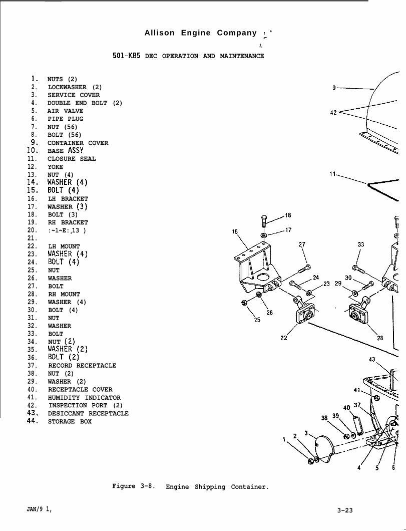
Allison Engine Company ,: ‘
1.2.3.4.5.6.7.8.
1::11.12.13.
;;:16.17.18.19.20.21.22.23.24.25.26.27.28.29.30.31.32.33.34.35.36.37.38.29.40.41.42.
;::
.!,
501-KB5 DEC OPERATION AND MAINTENANCE
NUTS (2)LOCKWASHER (2)SERVICE COVERDOUBLE END BOLT (2)AIR VALVEPIPE PLUGNUT (56)BOLT (56)CONTAINER COVERBASE ASSYCLOSURE SEALYOKENUT (4)W&lE~4~4)
LH BRACKETWASHER (3).-,BOLT (3)RH BRACKET:~l~E: 313 )
LH MOUNTh&U~E~4~4)
NUTWASHERBOLTRH MOUNTWASHER (4)BOLT (4)NUTWASHERBOLTNUT (Z)l’1:’l;E~2\2)
RECORD RECEPTACLENUT (2)WASHER (2)RECEPTACLE COVERHUMIDITY INDICATORINSPECTION PORT (2)DESICCANT RECEPTACLESTORAGE BOX
/9—
Figure 3-8. Engine Shipping Container.
JAN/9 1, 3-23
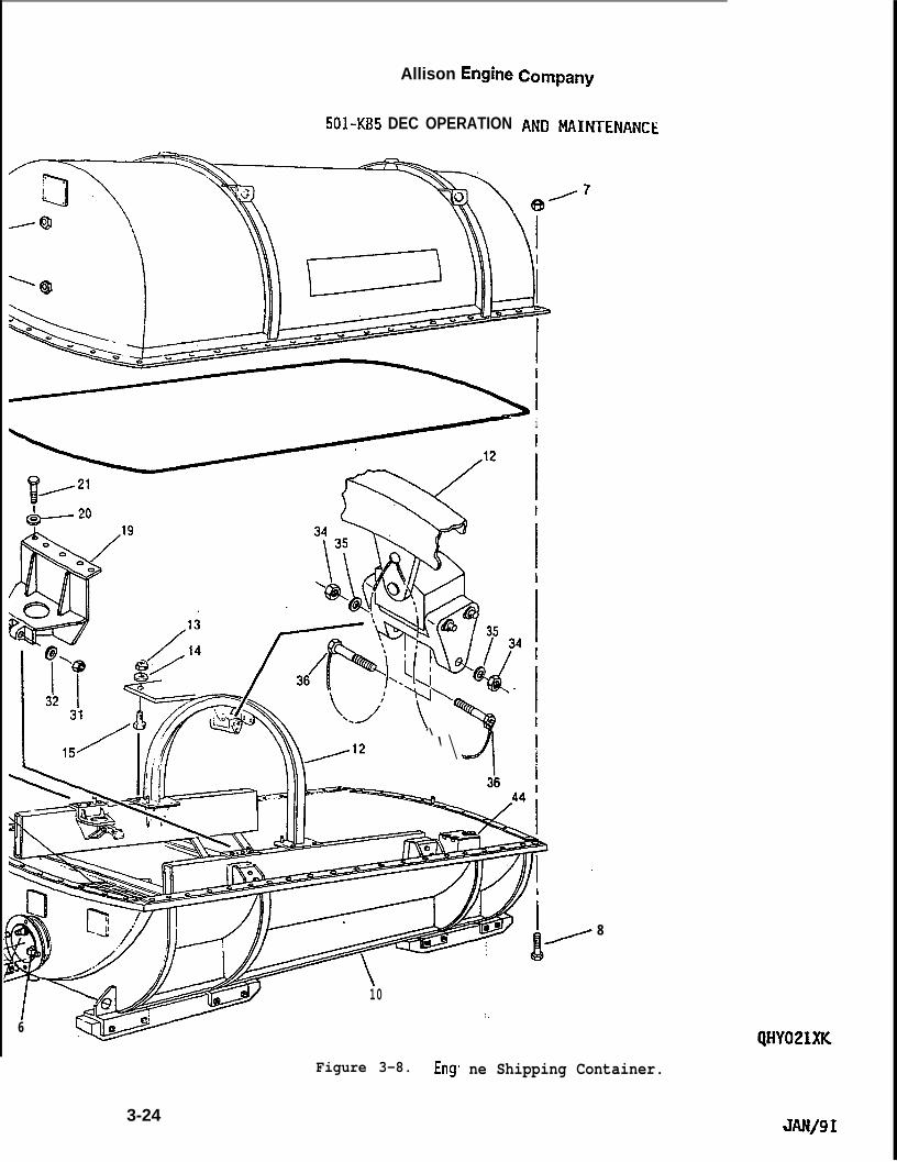
Allison Engine
501-KB5 DEC OPERATION
i
‘\
‘\d
8
\
—
10:.
6
Figure 3-8. Eng ne Shipping Container.
3-24JAN/91

Allison Engine Company
501-KB5 DEC OPERATION AND MAINTENANCE
14.
15.
16.
17.
18.
19.
20.
21.
22.
23.
Hoist engine up sufficiently to place base assembly (12) underengine.
Lower engine and align RH bracket (19), LH bracket (16), and yoke(12) mounting holes to mounting holes in base assembly (10).Secure with bolts (15, 18, and 21), washer (14, 17, and 20), andnuts (13). Lower engine to rest on base assembly. Torque bolts(18 and 21) and nuts (13) to 480-690 lb in. (54.2 -77.9 Nom).
Remove engine lifting adapter from engine.
Torque nuts (25 and 31), that secure mounts (22 and 28) tobrackets (16 and 19) to 1100-1300 lb in. (124.4-146.9 Nom).
Attach lift hooks to container cover (9) and lift up and over baseassembly (10).
Make sure closure seal (11) is aligned properly on the baseassembly (10) mounting flange.
Lower container cover (9) carefully over engine and align theguide pin hole with guide pin located on forward end of baseassembly (10) and secure with bolts (8) and nuts (7) with boltsheads down. Prior to final torque, tighten a nut (7) at eachcorner and each midpoint. Remove lift hooks from containercover. Torque all nuts to 600-840 lb in. (67.8-95.0 Nom).
If required, install pipe plug (6). Torque pipe plug to 205-245lb in. (23.6-27.6 N”m).
Service shipping container with compressed dry nitrogen per StepD.
Install records into record receptacle (37) and secure receptaclecover (40) with nuts (38) and washers (39): Torque nuts to” 30-45lb in. (3.9-5.ON”m).
NOTE
If tamper proof seals are available use them. Tamper proof seals arenot required for engine returning for rework.
24. Install lockwire on the record receptacle (37) and receptaclecover (40). Install a tamper proof seal on lockwire.
25. Install lockwire on the service cover (3) and shipping container.Install a tamper proof seal on lockwire.
26. Install lockwire on the shipping container RH and LH corners.Install tamper proof seal on each lockwire.
JAN/91 3-25
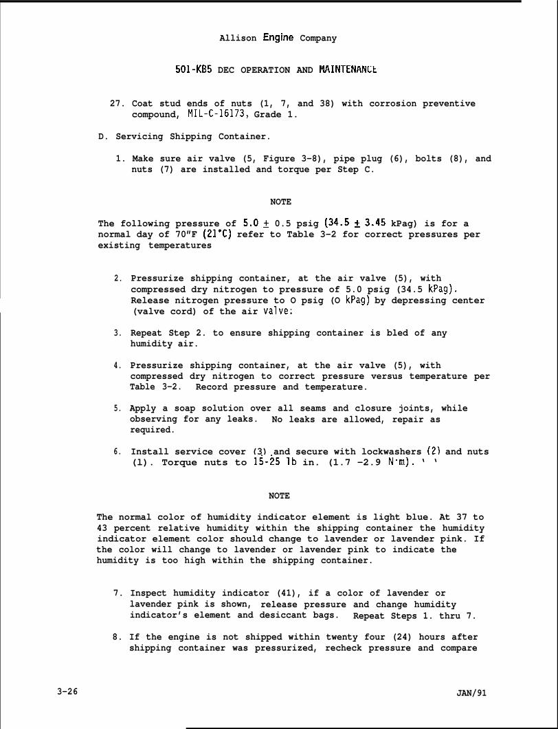
Allison Engine Company
501-KB5 DEC OPERATION AND MAINTENANLt
27. Coat stud ends of nuts (1, 7, and 38) with corrosion preventivecompound, MIL-C-16173, Grade 1.
D. Servicing Shipping Container.
1. Make sure air valve (5, Figure 3-8), pipe plug (6), bolts (8), andnuts (7) are installed and torque per Step C.
NOTE
The following pressure of 5.02 0.5 psig (34.5 ~3.45 kPag) is for anormal day of 70”F (21”C) refer to Table 3-2 for correct pressures perexisting temperatures
2.
3.
4.
5.
6.
Pressurize shipping container, at the air valve (5), withcompressed dry nitrogen to pressure of 5.0 psig (34.5 kPag).Release nitrogen pressure to O psig (O kPag) by depressing center(valve cord) of the air valve:
Repeat Step 2. to ensure shipping container is bled of anyhumidity air.
Pressurize shipping container, at the air valve (5), withcompressed dry nitrogen to correct pressure versus temperature perTable 3-2. Record pressure and temperature.
Apply a soap solution over all seams and closure joints, whileobserving for any leaks. No leaks are allowed, repair asrequired.
Install service cover (3) and secure with lockwashers (2) and nuts(l). Torque nuts to 15-251b in. (1.7 -2.9 N”m). ‘ ‘
NOTE
The normal color of humidity indicator element is light blue. At 37 to43 percent relative humidity within the shipping container the humidityindicator element color should change to lavender or lavender pink. Ifthe color will change to lavender or lavender pink to indicate thehumidity is too high within the shipping container.
7. Inspect humidity indicator (41), if a color of lavender orlavender pink is shown, release pressure and change humidityindicator’s element and desiccant bags. Repeat Steps 1. thru 7.
8. If the engine is not shipped within twenty four (24) hours aftershipping container was pressurized, recheck pressure and compare
3-26 JAN/91
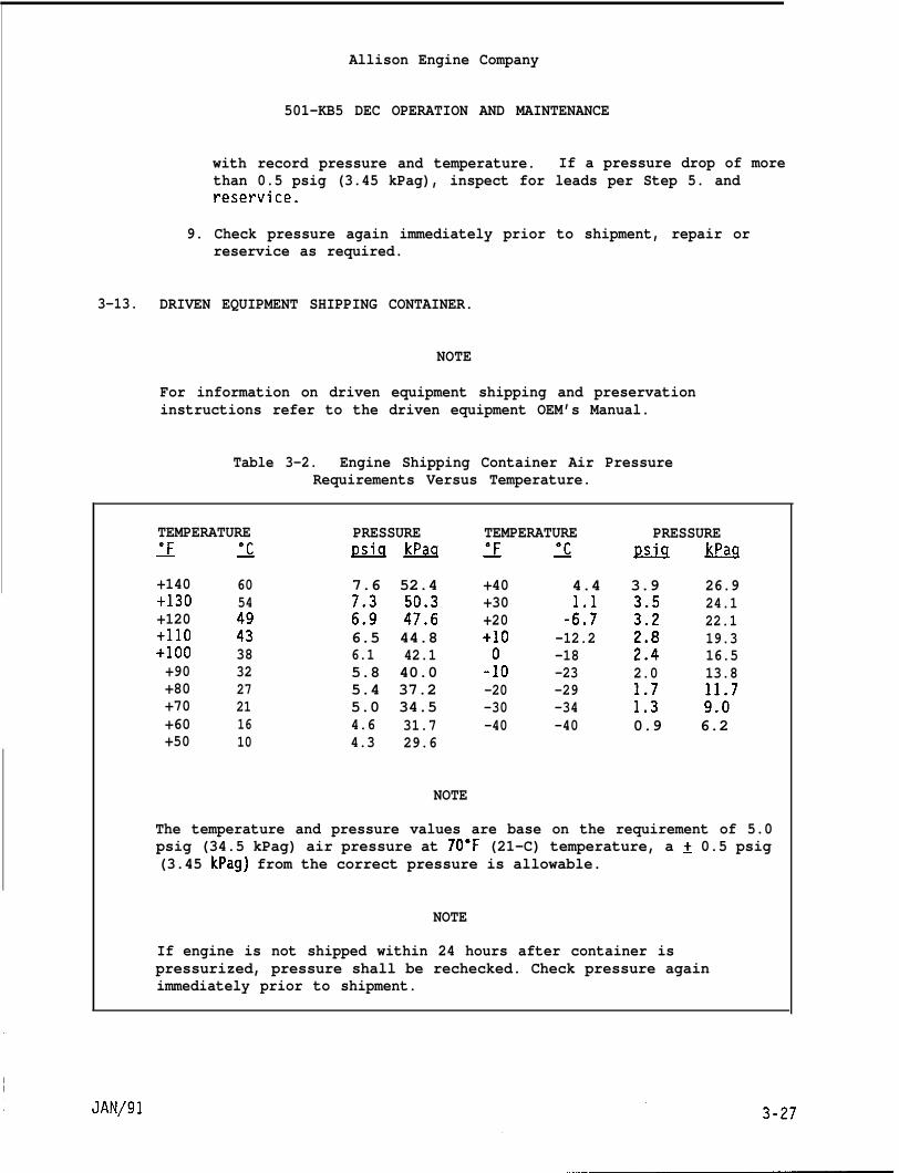
Allison Engine Company
501-KB5 DEC OPERATION AND MAINTENANCE
with record pressure and temperature. If a pressure drop of morethan 0.5 psig (3.45 kPag), inspect for leads per Step 5. andreservice.
9. Check pressure again immediately prior to shipment, repair orreservice as required.
3-13. DRIVEN EQUIPMENT SHIPPING CONTAINER.
NOTE
For information on driven equipment shipping and preservationinstructions refer to the driven equipment OEM’s Manual.
Table 3-2. Engine Shipping Container Air PressureRequirements Versus Temperature.
TEMPERATURE PRESSURE TEMPERATURE PRESSURE~ ~ ~ ~ ~ ~ J2QJ2 &
+140 60 7.6 52.4 +40 4.4 3.9 26.9+130 54 +30 24.1+120 ;:; :;:: +20 -::; ::; 22.1+110 :; 6.5 44.8 +10 -12.2 19.3+100 38 6.1 42.1 -18 ;:: 16.5+90 32 5.8 40.0 -!0 -23 2.0 13.8+80 27 5.4 37.2 -20 -29+70 21 5.0 34.5 -30 -34 ;:; ;!07+60 16 4.6 31.7 -40 -40 0.9 6.2+50 10 4.3 29.6
NOTE
The temperature and pressure values are base on the requirement of 5.0psig (34.5 kPag) air pressure at 70”F (21-C) temperature, a ~ 0.5 psig(3.45 kPag) from the correct pressure is allowable.
NOTE
If engine is not shipped within 24 hours after container ispressurized, pressure shall be rechecked. Check pressure againimmediately prior to shipment.
3-14.
3-15.
3-28
Allison Engine Company
501-KB5 DEC OPERATION AND MAINTENANCE
FUEL SYSTEM PRESERVATION.
NOTE
The fuel system shall be preserved in accordance with the PreservationProcedures in applicable paragraphs of Section 4 as they refer to thespecific type of control system.
ENGINE REMOVAL AND INSTALLATION.
CAUTION
THE PROCEDURES AND SEQUENCES OF REMOVING AND INSTALLING THE VARIOUSEXTERNALLY ENGINE MOUNTED COMPONENTS ARE AT THE DISCRETION OF THECOMPETENT MECHANIC USING THE CORRECT OEM’S MANUAL INSTRUCTIONS.
JAN/91
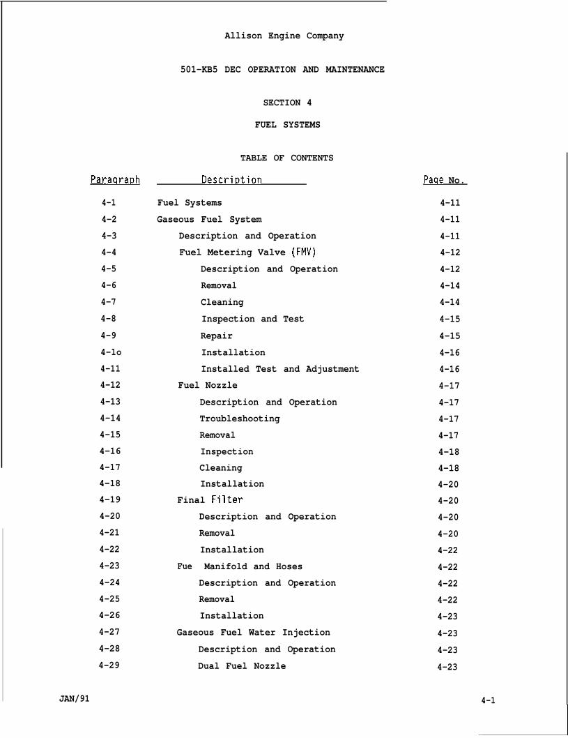
Paraqra~h
4-1
4-2
4-3
4-4
4-5
4-6
4-7
4-8
4-9
4-1o
4-11
4-12
4-13
4-14
4-15
4-16
4-17
4-18
4-19
4-20
4-21
4-22
4-23
4-24
4-25
4-26
4-27
4-28
4-29
JAN/91
Allison Engine Company
501-KB5 DEC OPERATION AND MAINTENANCE
SECTION 4
FUEL SYSTEMS
TABLE OF CONTENTS
Descri~tion
Fuel Systems
Gaseous Fuel System
Description and Operation
Fuel Metering Valve (FMV)
Description and Operation
Removal
Cleaning
Inspection and Test
Repair
Installation
Installed Test and Adjustment
Fuel Nozzle
Description and Operation
Troubleshooting
Removal
Inspection
Cleaning
Installation
Final Filter
Fue
Description and Operation
Removal
Installation
Manifold and Hoses
Description and Operation
Removal
Installation
Gaseous Fuel Water Injection
Description and Operation
Dual Fuel Nozzle
Pacie No.
4-11
4-11
4-11
4-12
4-12
4-14
4-14
4-15
4-15
4-16
4-16
4-17
4-17
4-17
4-17
4-18
4-18
4-20
4-20
4-20
4-20
4-22
4-22
4-22
4-22
4-23
4-23
4-23
4-23
4-1
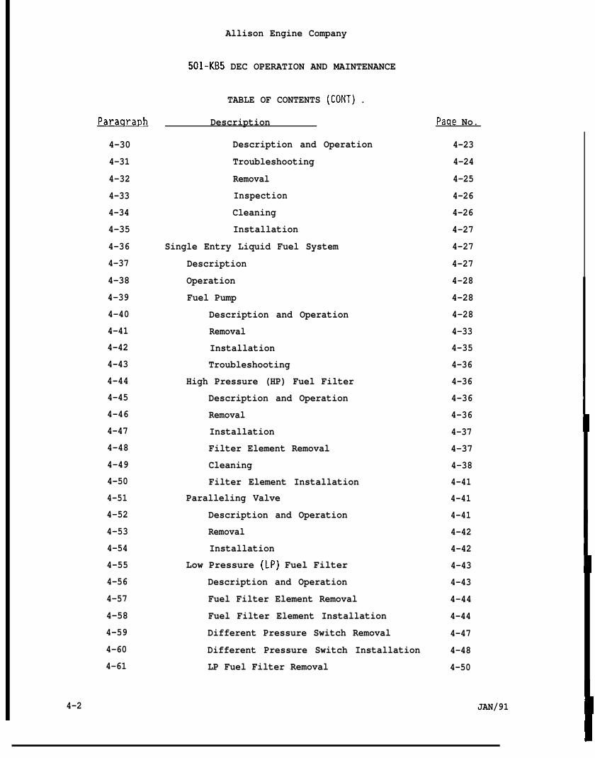
Allison Engine Company
501-KB5 DEC OPERATION AND MAINTENANCE
TABLE OF CONTENTS (CONT) .
Paraqra~h
4-30
4-31
4-32
4-33
4-34
4-35
4-36
4-37
4-38
4-39
4-40
4-41
4-42
4-43
4-44
4-45
4-46
4-47
4-48
4-49
4-50
4-51
4-52
4-53
4-54
4-55
4-56
4-57
4-58
4-59
4-60
4-61
Description
Description and Operation
Troubleshooting
Removal
Inspection
Cleaning
Installation
Single Entry Liquid Fuel System
Description
Operation
Fuel Pump
Description and Operation
Removal
Installation
Troubleshooting
High Pressure (HP) Fuel Filter
Description and Operation
Removal
Installation
Filter Element Removal
Cleaning
Filter Element Installation
Paralleling Valve
Description and Operation
Removal
Installation
Low Pressure (LP) Fuel Filter
Description and Operation
Fuel Filter Element Removal
Fuel Filter Element Installation
Different Pressure Switch Removal
Different Pressure Switch Installation
LP Fuel Filter Removal
Paqe No.
4-23
4-24
4-25
4-26
4-26
4-27
4-27
4-27
4-28
4-28
4-28
4-33
4-35
4-36
4-36
4-36
4-36
4-37
4-37
4-38
4-41
4-41
4-41
4-42
4-42
4-43
4-43
4-44
4-44
4-47
4-48
4-50
4-2 JAN/91
Allison Engine Company
501-KB5 DEC OPERATION AND MAINTENANCE
Paraqra~h
4-62
4-63
4-64
4-65
4-66
4-67
4-68
4-69
4-70
4-71
4-72
4-73
4-74
4-75
4-76
4-77
4-78
4-79
4-80
4-81
4-82
4-83
4-84
4-85
4-86
4-87
4-88
4-89
4-90
4-91
4-92
4-93
TABLE OF CONTENTS (CONT) .
Descri~tion
LP Fuel Filter Installation
Pressure Relief Valve
Description and Operation
Removal
Installation
Fuel Metering Valve (FMV)
Description and Operation
Removal
Installation
Fuel Shutoff Valve
Description and Operation
Inspection
Removal
Installation
Manifold Drain Valve
Description and Operation
Removal
Installation
Inspection and Test
Burner Drain Valves
Description and Operation
Removal
Maintenance and Inspection
Installation
Troubleshooting
Fuel Lines and Hoses
Single Entry Fuel Nozzle (Fuel Nozzle)
Description and Operation
Removal
Inspection
Cleaning
Installation
Pacle No.
4-51
4-53
4-53
4-53
4-54
4-56
4-56
4-56
4-57
4-60
4-60
4-60
4-61
4-62
4-63
4-63
4-63
4-63
4-64
4-65
4-65
4-65
4-65
4-66
4-67
4-67
4-67
4-67
4-68
4-70
4-70
4-72
I JAN/91 4-3
I
Allison Engine Company
Paraqraph
4-94
4-95
4-96
4-97
4-98
4-99
4-1oo
4-101
4-102
4-103
4-104
4-105
4-106
4-107
4-108
4-109
4-110
4-111
4-112
4-113
4-114
4-115
4-116
4-117
4-118
4-119
4-120
4-121
4-122
4-123
4-4
501-KB5 DEC OPERATION AND MAINTENANCE
TABLE OF CONTENTS (CONT) .
Descri~tion
Liquid Fuel Water Injection
Description and Operation
Flow Divider Valve
Description and Operation
Removal
Maintenance
Installation
Manifold Drain Valves
Description and Operation
Pilot Manifold Drain Valve Removal
Pilot Manifold Drain Valve
Installation
Main Manifold Drain Valve Removal
Main Manifold Drain Valve
Installation
Liquid Fuel Nozzle
Description and
Removal
Inspection
Cleaning
Installation
Operation
Fuel Manifold (Pilot and Main)
Description and Operation
Removal and Installation
Dual Entry Fuel System
Description
Operation
Fuel Pump
High Pressure (HP) Fuel Filter
Paralleling Valve
Low Pressure (LP) Fuel Filter
Pressure Relief Valve
Paqe No.
4-73
4-73
4-73
4-73
4-74
4-74
4-77
4-77
4-77
4-80
4-80
4-81
4-82
4-82
4-82
4-83
4-84
4-84
4-86
4-86
4-86
4-87
4-87
4-87
4-88
4-88
4-88
4-91
4-91
4-91
JAN/91
Allison Engine Company
501 -KB5 DEC OPERATION AND MAINTENANCE
ParaQra~h
4-124
4-125
4-126
4-127
4-128
4-129
4-130
4-131
4-132
4-133
4-134
4-135
4-136
4-137
4-138
4-139
4-140
4-141
4-142
4-143
4-144
4-145
4-146
4-147
4-148
4-149
4-150
4-151
4-152
4-153
4-154
4-155
TABLE OF CONTENTS (CONT) .
Descri~tion
Fuel Metering Valve (FMV)
Fuel Shutoff Valve
Flow Divider Valve
Burner Drain Valves
Fuel Lines and Hoses
Fuel Manifolds (Pilot and Main)
Fuel Nozzles (Dual Entry)
Description and Operation
Removal
Inspection
Cleaning
Installation
Manifold Drain Valves
Description and Operation
Removal
Installation
Dual Entry Fuel Water Injection System
Description and Operation
Dual Fuel System
Description and Operation
Low Pressure (LP) Fuel Filter Assembly
Description and Operation
Filter Element Removal
Filter Element Installation
Removal
Installation
High Pressure (HP) Fuel Filter Assembly
Description and Operation
Filter Element Removal
Cleaning
Filter Element Installation
Removal
Paqe No.
4-91
4-91
4-91
4-91
4-92
4-92
4-92
4-92
4-93
4-94
4-95
4-96
4-97
4-97
4-98
4-98
4-98
4-98
4-98
4-98
4-99
4-99
4-99
4-1oo
4-103
4-103
4-106
4-106
4-106
4-106
4-106
4-106
JAN/91 4-5
Paraaraph
4-156
4-157
4-158
4-159
4-160
4-161
4-162
4-163
4-164
4-165
4-166
4-167
4-168
4-169
4-170
4-171
4-172
4-173
4-174
4-175
4-176
4-177
4-178
4-179
4-180
4-181
4-182
4-183
4-184
4-185
4-186
4-187
4-6
Allison Engine Company
501-KB5 DEC OPERATION AND MAINTENANCE
TABLE OF CONTENTS (CONT) .
Descri~tion
Installation
Liquid Fuel Pump
Description and Operation
Removal
Installation
Liquid Fuel Metering Valve (FMV)
Paqe No.
4-107
4-107
4-107
4-107
4-108
4-109
Description and
Removal
Installation
Liquid Fuel Shutoff
Description and
Removal
Installation
Liquid Fuel Shutoff
Description and
Removal
Installation
Flow Divider Valve
Description and
Removal
Installation
Operation
Valve
Operation
Valve (Ball Type)
Operation
Operation
Manifold Drain Valves (Pilot and Main)
Description and Operation
Main Manifold Drain Valve Removal
4-109
4-109
4-114
4-115
4-115
4-115
4-116
4-116
4-116
4-117
4-118
4-118
4 - 1 1 8
4-119
4-122
4-123
4-123
4-124
Main Manifold Drain Valve Installation 4-124
Pilot Manifold Drain Valve Removal 4-125
Pilot Manifold Drain Valve Installation 4-126
Fuel Manifold (Pilot and Main) 4-126
Description and Operation 4-126
Removal and Installation 4-127
Dual Fuel Nozzle 4-127
Description and Operation 4-127
JAN/91
Paraqra~h
4-188
4-189
4-190
4-191
4-192
4-193
4-194
4-195
4-196
4-197
4-198
4-199
4-200
4-201
4-202
4-203
4-204
4-205
4-206
4-207
4-208
4-209
4-210
4-211
4-212
4-213
4-214
4-215
4-216
4-217
4-218
4-219
JAN/91
Allison Engine Company
501-KB5 DEC OPERATION AND MAINTENANCE
TABLE OF CONTENTS
Descri~tion
Removal
Inspection
Cleaning
Installation
Pressure Relief Valve
(CONT) .
Description and Operation
Removal
Installation
Parallel Air Control Valve
Description and Operation
Gaseous Fuel Purge Valves
Description and Operation
Removal
Installation
Liquid Fuel Outlet Bypass Valve
Description and Operation
Removal
Installation
Liquid Fuel Heating Bypass Valve
Description and Operation
Removal
Installation
Liquid Fuel Pressure Switch
Description and Operation
R e m o v a l
Installation
Gaseous Fuel Shutoff and Vent Valves
Description and Operation
Gaseous Fuel Filter
Description and Operation
Removal
Installation
Paqe No.
4-128
4-129
4-130
4-131
4-132
4-132
4-132
4-133
4-133
4-133
4-133
4-133
4-134
4 - 1 3 4
4-135
4-135
4-135
4-136
4-136
4-136
4-137
4-137
4-138
4-138
4-138
4-139
4-139
4-139
4-139
4-139
4-140
4-140
4-7

4-8
Paraqra~h
4-220
4-221
4-222
4-223
4-224
4-225
4-226
4-227
4-228
4-229
4-230
4-231
4-232
4-233
4-234
4-235
4-236
4-237
4-238
4-239
4-240
4-241
Fiqure No.
4-1
4-2
4-3
4-4
Allison Engine Company
501-KB5 DEC OPERATION AND MAINTENANCE
TABLE OF CONTENTS (CONT) ,
Descrir)tion
Gaseous Fuel Metering Valve
Description and Operation
Removal
Clean, Inspect, Test, and Repair
Installation
Gaseous Differential Pressure Switch
Description and Operation
Removal
Installation
Gaseous Fuel Pressure Switch
Description and Operation
Removal
Installation
Gaseous Fuel Manifold and Hoses
Description and Operation
Gaseous Fuel Manifold Removal
Gaseous Fuel Manifold Installation
Gaseous Fuel Manifold Hoses Remova”
and Installation
Dual Fuel Water Injection System
Description and Operation
Optional Liquid Fuel Heating System
Description and Operation
INDEX TO FIGURES
Gaseous Fuel System Schematic
Gaseous Fuel System Components
Gaseous Fuel Nozzle
Gaseous Fuel Water Injection System
Paqe No.
4-141
4-141
4-141
4-142
4-142
4-143
4-143
4-144
4-144
4-145
4-145
4-146
4-146
4-147
4-147
4-147
4-148
4-150
4-150
4-150
4-150
4-150
Paqe No.
4-13
4-19
4-21
4-24
JAN/91
Allison Engine Company
501-KB5 DEC OPERATION AND MAINTENANCE
INDEX TO FIGURES (CONT) .
Fiaure No. Title Paqe No.
4-5
4-6
4-7
4-8
4-9
4-1o
4-11
4-12
4-13
4-14
4-15
4-16
4-17
4-18
4-19
4-20
4-21
4-22
4-23
4-24
4-25
4-26
4-27
4-28
4-29
4-30
JAN/91
Gaseous Fuel Nozzle Water Injection System
Single Entry Liquid Fuel System Schematic
Liquid Fuel Pump and HP Fuel Filter
High Pressure Fuel Filter
High Pressure (HP) Fuel Filter Element
Cross Section
Paralleling Valve O-ring and Valve Seat
Installation
Low Pressure Fuel Filter Assembly
Use of Spring Depressor, 6796975
Use of Pliers, 6796974
Differential Pressure Switch and LP Fuel Filter
Pressure Relief Valve, Fuel Shutoff Valve,
and Manifold Drain Valve
Fuel Metering Valve (FMV)
Burner Drain Valves
Single Entry Liquid Fuel Nozzle Schematic
Single Entry Liquid Fuel Nozzle
Liquid Fuel Water Injection Schematic
Flow Divider and Manifold Drain Valves
Liquid Fuel Water Injection Fuel Nozzle
Dual Entry Fuel System Schematic
Dual Entry Fuel Nozzle
Removal and Installation of Dual Entry
Fuel Nozzle
Dual Fuel System Schematic
Off-Engine Mounted Fuel Pump and Filter
Assemblies
RAFT Mounted Components
RAFT Junction Box Terminals
Flow Divider and Manifold Drain Valves
4-25
4-31
4-34
4-39
4-41
4-43
4-45
4-46
4-46
4-49
4-55
4-59
4-66
4-69
4-71
4-75
4-79
4-83
4-89
4-93
4-96
4-101
4-105
4-111
4-113
4-121
4-9
4-1o
Fiqure No.
4-31
4-32
4-33
4-34
4-35
-
Allison Engine Company
501-KB5 DEC OPERATION AND MAINTENANCE
INDEX TO FIGURES (CONT) .
Title Paqe No.
Dual Fuel Nozzle 4-129
Gaseous Fuel Manifold and Hoses 4-149
Dual Fuel Water Injection System 4-151
Dual Fuel Heating System 4-153
Single or Dual Entry Fuel Heating Systems 4-155
INDEX TO TABLES
Table No. T i t l e Paqe No.
4-1 Approved Liquid Fuels 4-29
JAN/91
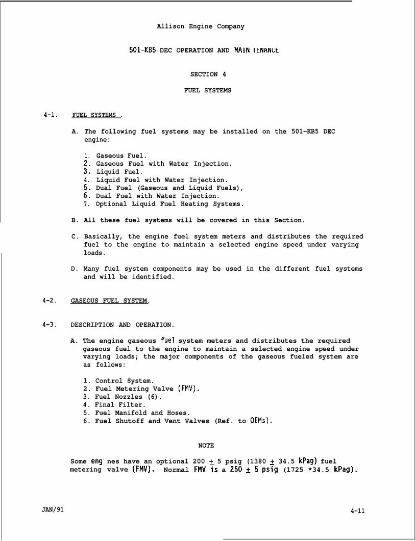
4-1.
4-2.
4-3.
Allison Engine Company
501-KB5 DEC OPERATION AND MAIN ItNANLt
SECTION 4
FUEL SYSTEMS
FUEL SYSTEMS .
A. The following fuel systems may be installed on the 501-KB5 DECengine:
1.
::4.
::7.
Gaseous Fuel.Gaseous Fuel with Water Injection.Liquid Fuel.Liquid Fuel with Water Injection.Dual Fuel (Gaseous and Liquid Fuels),Dual Fuel with Water Injection.Optional Liquid Fuel Heating Systems.
B. All these fuel systems will be covered in this Section.
C. Basically, the engine fuel system meters and distributes the requiredfuel to the engine to maintain a selected engine speed under varyingloads.
D. Many fuel system components may be used in the different fuel systemsand will be identified.
GASEOUS FUEL SYSTEM.
DESCRIPTION AND OPERATION.
A. The engine gaseous fuel system meters and distributes the requiredgaseous fuel to the engine to maintain a selected engine speed undervarying loads; the major components of the gaseous fueled system areas follows:
1. Control System.2. Fuel Metering Valve (FMV).3. Fuel Nozzles (6).4. Final Filter.5. Fuel Manifold and Hoses.6. Fuel Shutoff and Vent Valves (Ref. to OEMS).
Some eng”metering
NOTE
nes have an optional 200 + 5 psig (1380 + 34.5 kPag) fuelvalve (FMV). Normal FMV~s a 250~5 ps~g (1725 *34.5 kPag).
4-11JAN/91
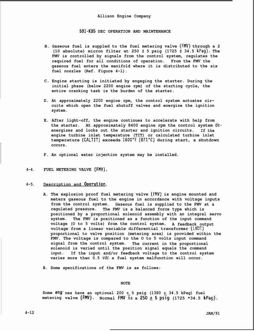
Allison Engine Company
501-KB5 DEC OPERATION AND MAINTENANCE
B. Gaseous fuel is suppled to the fuel metering valve (FMV) through a 2(10 absolute) micron filter at 250 i 5 psig (1725 t 34.5 kPag). TheFMV is controlled by signals from the control system, regulates therequired fuel for all conditions of operation. From the FMV thegaseous fuel enters the manifold where it is distributed to the sixfuel nozzles (Ref. Figure 4-l).
C. Engine starting is initiated by engaging the starter. During theinitial phase (below 2200 engine rpm) of the starting cycle, theentire cranking task is the burden of the starter.
D. At approximately 2200 engine rpm, the control system actuates cir-cuits which open the fuel shutoff valves and energize the ignitionsystem.
E. After light-off, the engine continues to accelerate with help fromthe starter. At approximately 8400 engine rpm the control system de-energizes and locks out the starter and ignition circuits. If theengine turbine inlet temperature (TIT) or calculated turbine inlettemperature (CALTIT) exceeds 1600”F (871”C) during start, a shutdownoccurs.
F. An optional water injection system may be installed.
4-4. FUEL METERING VALVE (FMV).
4-5. Description and Or.)eration.
4-12
A. The explosion proof fuel metering valve (FMV) is engine mounted andmeters gaseous fuel to the engine in accordance with voltage inputsfrom the control system. Gaseous fuel is supplied to the FMV at aregulated pressure. The FMV is a balanced force type which ispositioned by a proportional solenoid assembly with an integral servosystem. The FMV is positioned as a function of the input commandvoltage (O to 5 volts) from the control system. A feedback outputvoltage from a linear variable differential transformer (LVDT)proportional to valve position (metering area) is provided within theFMV. The voltage is compared to the O to 5 volts input commandsignal from the control system. The current in the proportionalsolenoid is varied until the position signal equals the commandinput. If the input and/or feedback voltage to the control systemvaries more than 0.5 vdc a fuel system malfunction will occur.
B. Some specifications of the FMV is as follows:
Some eng.metering
NOTE
nes have an optional 200 + 5 psig (1380 + 34.5 kPag) fuelvalve (FMV). Normal FMV~s a 250~5 ps{g (1725 *34.5 kPag).
JAN/91
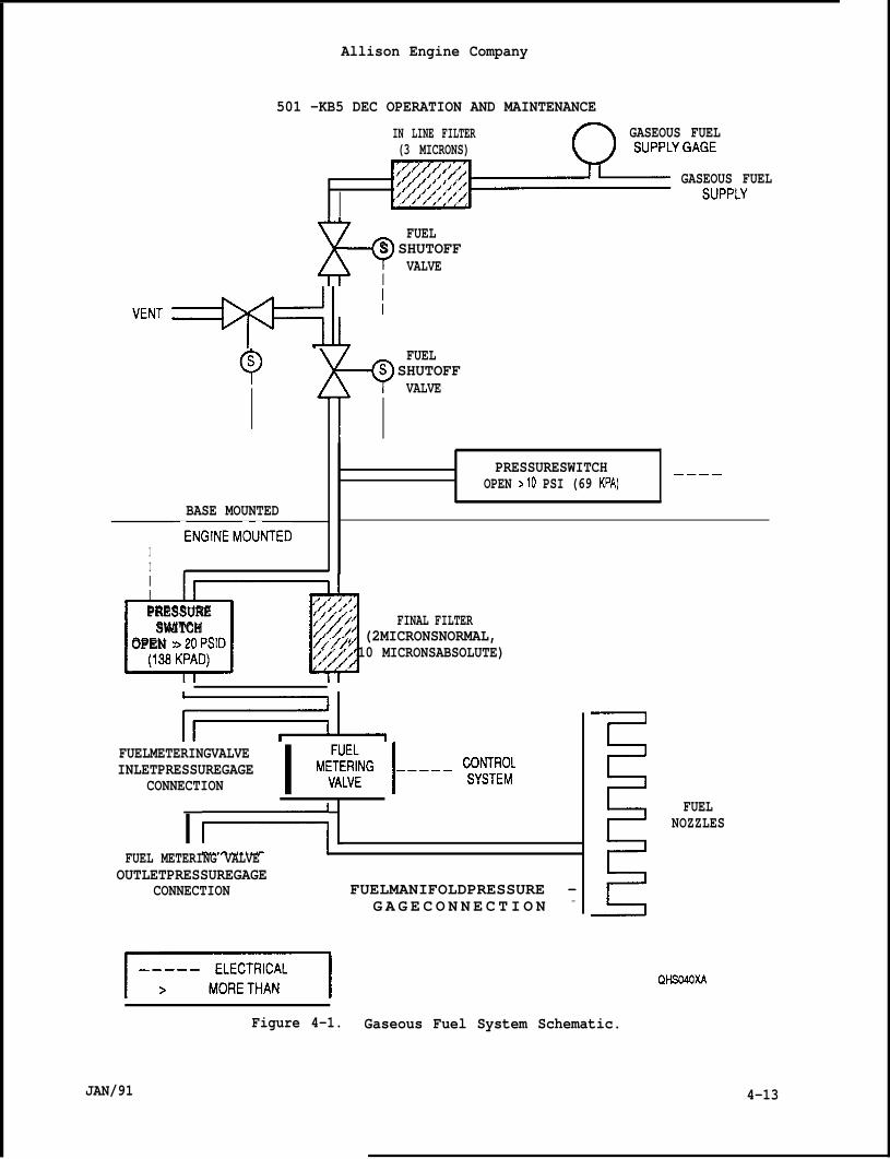
Allison Engine Company
501 -KB5 DEC OPERATION AND MAINTENANCE
IN LINE FILTER GASEOUS FUEL(3 MICRONS)
GASEOUS FUEL
Ix-? FUELS SHUTOFF
VALVE
‘ENT+’ ‘
BASE MOUNTED
‘ENGINEMO~NTEDII *
)--Q FUELS SHUTOFF
I
VALVE
PRESSURESWITCHOPEN >10 PSI (69 KPA)
————
rlPRESSURESWITCH
OPEN >20PSID u;/j,,;, FINAL FILTER::$;2 (2MICRONSNORMAL,“j{~~? 10 MICRONSABSOLUTE):,,#jj’,##
FUELMETERINGVALVEINLETPRESSUREGAGE
CONNECTION I ‘~NG l----fi:~:I r+.
FUEL METERING VALVEOUTLETPRESSUREGAGE
CONNECTION FUELMANIFOLDPRESSURE —G A G E C O N N E C T I O N —
F==l
FUELNOZZLES
QWXA
JAN/91
Figure 4-1. Gaseous Fuel System Schematic.
4-13
4-6.
4-7.
4-14
1.
2.
3.
4.
5.
Allison Engine Company
501 -KB5 DEC OPERATION AND MAINTENANCE
Operating pressure - 250 t 5 psig (1725 t 34.5 kPag).
Leakage - No leaks from splitlines, holes, or casting.
Response - Maximum transient time response is 0.120 seconds.
Ambient Temperature - Operates satisfactorily in surrounding airtemperature of -40° to 160”F (-40° to 71”C)0
Fuel Temperature - Operates satisfactorily with fuel temperaturesfrom -40: to 160”F (~40° to 71°C). -
Removal.
A. Make sure electrical power is OFF and remains OFF until installationis completed.
B. Make sure gaseous fuel is OFF and no pressure is at the inlet to theFMV .
CAUTION
DO NOT DISCONNECT FMV ELECTRICAL LEADS INSIDE THE FMV. DAMAGE TO THEFMV WILL OCCUR.
C. Remove FMV electrical leads (1, Figure 4-2) at point of interfacewith the control system.
D. Remove bolts (2), fuel manifold (3), and gasket (4). Discard gasket.
E. Remove FMV outlet gage pressure hose (5).
F. Remove FMV inlet gage pressure hose (6).
G. Remove bolts (7) and washers (8).
H. Move adapter assemble (9) and remove gasket (10). Discard gasket.
I. Remove nuts (11) and remove FMV (16) with bracket (13).
J. Remove bolts (12) and bracket (13) from FMV (16).
K. If required, remove unions (14) and O-rings (15) from FMV (16).Discard O-rings.
Cleaninq.
A. Because of the electrical circuits, do not submerge the FMV incleaning solvent.
JAN/91
Allison Engine Company
501-KB5 DEC OPERATION AND MAINTENANCE
B. The non-electrical (lower) part of the FMV may be cleaned withmineral spirits.
C. A-27 cleaner by Pennwalt Corporation (3 Penn Center, Philadelphia, PA19102) may be used in nonelectrical areas. FOI1OW manufacturer’sinstructions. Usual mix is 3-10 ounces (89-296mL) to a gallon (3.79L) of water, heat and stir for 3-15 minutes.
D. Kemtex Safe Solvent can also be used. (MacDermid of Bristol Inc.,Bristol, Corm. or Sante Fe Springs, Calif.)
This solvent iscontains a rustcleaning and isburn.
1.
2.
Kemtex is
NOTE
much safer to use than carbon tetrachloride. Itinhibitor to temporarily prevent rusting of steel aftermuch safer to use than naphtha or benzene as it will not
a solvent for cleaning oily equipment and particularlyfor cleaning and drying electrical equipment and components.
It is a sliqhtl.y ~ink, clear liquid having a distinctive odor.This is a r;pid~drying, oil solvent having the unusual property ofdriving moisture ahead of it and then evaporating rapidly to leavea bone-dry surface. May be used to clean printed circuit boardsas well as metal parts. May be used in ultrasonic equipment.Will not attack aluminum, steel, brass, copper, magnesium, zinc orother metals under ordinary conditions of use. Will not harm mostpaints or varnishes, but will rapidly dissolve asphalt and oils.
4-8. Ins~ection and Test.
A. Accomplish the usual visual inspections to locate obvious mechanicalfailure such as broken wires, bare and shorting wires, and damagedhousing, flange adapter and threads.
B. If the FMV is shook, there should besomething is loose inside.
no rattle or sensation
CAUTION
DO NOT PROBE CIRCUIT LEADS WITH A CONTINUITY TESTER SUCH ASOHMS PER VOLT OHMMETER FOR SHORTS AND OPENS; TRANSIENTS MAYSOLID STATE DEVICE.
4-9. u“
feel that
A LOWDESTROY A
A. There is no disassembly, parts fix, or parts replacement allowed.Repair consists of installing a known good, new or overhauled FMV.
JAN/91 4-15
Allison Engine Company
501-KB5 DEC OPERATION AND MAINTENANCE
B. Certain obvious things such as fixingsplicing on a new wire (if accessible,touchup may be done.
4-1o. Installation.
the insulation of a bare wire,9 chasing threaded parts, paint
A. Wet O-rings (15, Figure 4-2) with clean engine oil.
B. Install an O-ring (15) on each union (14). Install unions in FMV(16). Torque unions to 55-80 lb in. (6.3 -9.0 N-m).
C. Install bracket (13) on FMV (16) and secure with bolts (12). Torquebolts to 120-150 lb in. (13.6-16.9 Nom) and lockwire.
D. Install assemble bracket and FMV to engine and secure with nuts(11). Torque nuts to 74-89 lb in. (8.4-10.0 N-m).
E. Install gasket (10) and adapter assembly (9) to FMV (16) and securewith washers (8) and bolts (7). Torque bolts to 70-85 lb in.(8.0-9.6 N-m) and lockwire.
F. Install FMV inlet gage pressure hose (6) to union (14). Retain union(14) from turning and torque hose’s coupling nut to 80-120 lb in.(9.0 -13.5 N“m).
G. Install FMV outlet gage pressure hose (5) to union (14). Retainunion (14) from turning and torque hose’s coupling nut to 80-120 lbin. (9.0 -13.5 N”m).
H. Install gasket (4) and manifold (3) to FMV (16) and secure with bolts(2). Torque bolts to 70-85 lb in. (8.0-9.6 N*m) and lockwire.
WARNING
MAKE SURE ELECTRICAL POWER IS OFF. DAMAGE OR INJURY MAY OCCUR.
I. Connect FMV leads (1) per color coding on FMV’S (16) identificationtag to the control system to complete the interface.
4-11. Installed Test and Adjustment.
A. Field adjustments to the FMV are not permitted.
B. Check operation of FMV via the control system by introducing to thecontrol signals which simulate engine operation.
4-16 JAN/91
Allison Engine Company
501-KB5 DEC OPERATION AND MAINTENANCE
4-12. FUEL NOZZLE.
4-13. Descrir)tion and O~eration,
A. The engine has six fuel nozzles. Each fuel nozzle is secured to thediffuser and extends into the forward end of the combustion liner.The gaseous fuel nozzle consists of two parts; the body assembly andthe body holder. The body assembly has ten holes at the exit throu~hwhich the
B. Disassemb”permitted
gaseous fuel is-directed-into the combustion liner.
ing the fuel nozzle body from the body holder is notat this level of maintenance.
4-14. Troubleshootinq.
Although the following troublemalfunctioning fuel nozzle(s),
NOTE
indications may be traceable toother devices, and/or a combination of
things can cause the same troubles.
A. Some symptoms which can lead to a fuel nozzle inspection:
1.
2.
3.
4.
5.
Frequent fail-to-start or slow or stagnated starts.
Excessive and frequent torching and/or smoking.
High incidence of thermocouple failures such as burned-off probetips and/or open thermocouple junctions.
Appearance of hot spots on the outer combustion case.
Excessive engine vibration which may result in erosion and/orcracking of the fuel nozzle bodies.-
4-15. Removal.
Individual gaseous
NOTE
fuel nozzles may
hose (20, Figure
contamination.
be replaced.
4-2) from the fuel nozzleA. Remove the fuel manifold(19).
B. Cap the hose to keep out
C. Remove bolts (17) and carefully remove fuel nozzle (19) and gasket(18). Discard gasket.
D. Repeat Steps A., B., and C. to required fuel nozzle(s) to be removed.
JAN/91 4-17
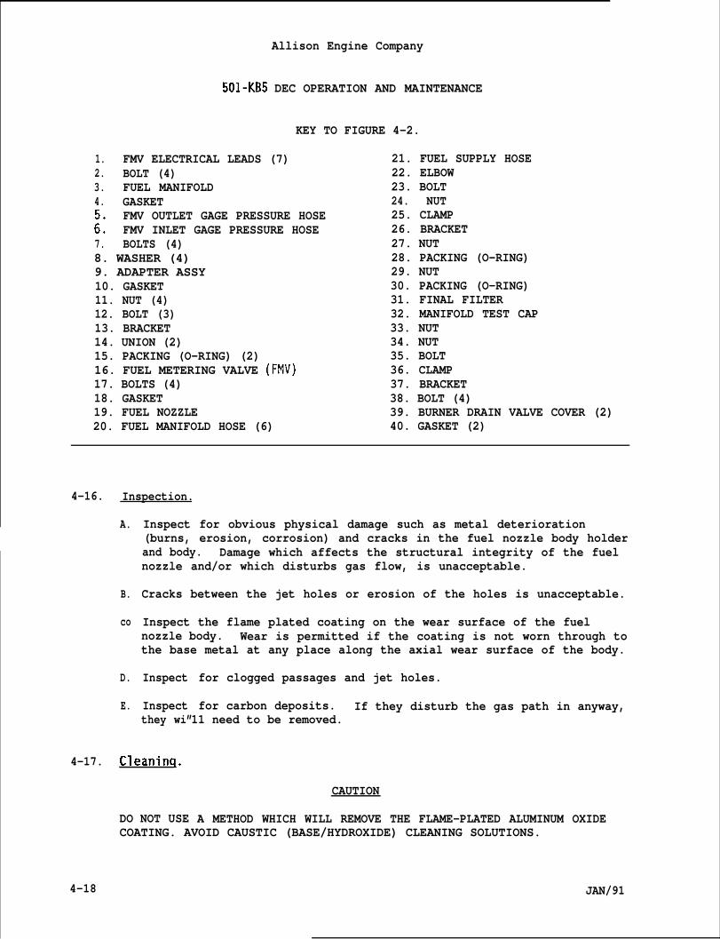
Allison Engine Company
501-KB5 DEC OPERATION AND MAINTENANCE
KEY TO FIGURE 4-2.
1. FMV ELECTRICAL LEADS (7)2. BOLT (4)3. FUEL MANIFOLD4. GASKET
FMV OUTLET GAGE PRESSURE HOSE:: FMV INLET GAGE PRESSURE HOSE7. BOLTS (4)8. WASHER (4)9. ADAPTER ASSY10. GASKET11. NUT (4)12. BOLT (3)13. BRACKET14. UNION (2)15. PACKING (O-RING) (2)16. FUEL METERING VALVE (FMV)17. BOLTS (4)18. GASKET19. FUEL NOZZLE20. FUEL MANIFOLD HOSE (6)
21. FUEL SUPPLY HOSE22. ELBOW23. BOLT24. NUT25. CLAMP26. BRACKET27. NUT28. PACKING (O-RING)29. NUT30. PACKING (O-RING)31. FINAL FILTER32. MANIFOLD TEST CAP33. NUT34. NUT35. BOLT36. CLAMP37. BRACKET38. BOLT (4)39. BURNER DRAIN VALVE COVER (2)40. GASKET (2)
4-16. Inspection.
A.
B.
co
D.
E.
Inspect for obvious physical damage such as metal deterioration(burns, erosion, corrosion) and cracks in the fuel nozzle body holderand body. Damage which affects the structural integrity of the fuelnozzle and/or which disturbs gas flow, is unacceptable.
Cracks between the jet holes or erosion of the holes is unacceptable.
Inspect the flame plated coating on the wear surface of the fuelnozzle body. Wear is permitted if the coating is not worn through tothe base metal at any place along the axial wear surface of the body.
Inspect
Inspect
for clogged passages and jet holes.
for carbon deposits. If they disturb the gas path in anyway,they wi”
4-17. Cleaninq.
11 need to be removed.
DO NOT USE
CAUTION
A METHOD WHICH WILL REMOVE THE FLAME-PLATED ALUMINUM OXIDECOATING. AVOID CAUSTIC (BASE/HYDROXIDE) CLEANING SOLUTIONS.
4-18 JAN/91
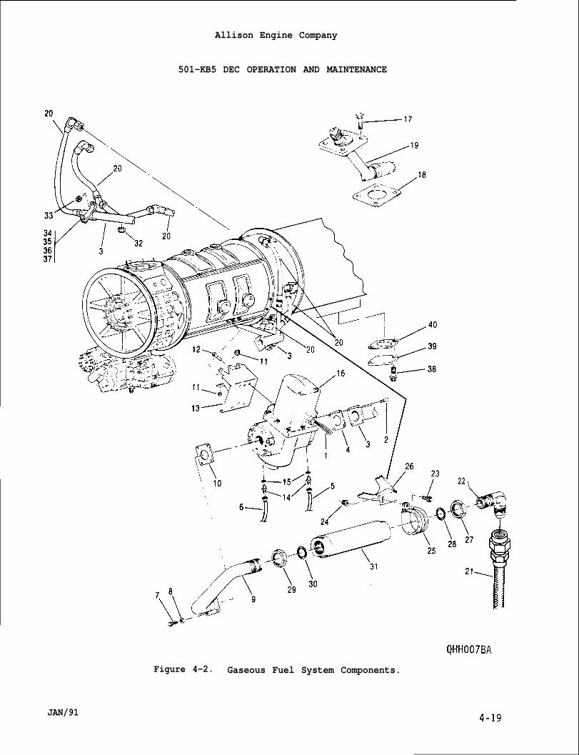
Allison Engine Company
501-KB5 DEC OPERATION AND MAINTENANCE
22 \
Figure 4-2. Gaseous Fuel System Components.
JAN/91
Allison Engine Company
501-KB5 DEC OPERATION AND MAINTENANCE
NOTE
In order to ascertain the amount of damage, cleaning may have toprecede inspection.
A. Use light pressure with a soft cloth and petroleum solvent. Ifnecessary, use a carbon solvent.
B. Dry with filtered compressed air.
CAUTION
DO NOTHING WHICH WOULD INCREASE THE HOLE SIZE. IF HOLE SIZE ISINCREASED REPLACE THE FUEL NOZZLE.
C. Assure that the spray orifices (jet holes) are open. If necessary,use an appropriate size probe to clean the orifices, such as a copperknife or wire. Hold fuel nozzle in such a position that scrapingsfall clear and not into the fuel nozzle (Ref. Figure 4-3).
4-18. Installation.
A. Install gasket (18, Figure 4-2).
B. Apply Ablube, MIL-L-25681, on the bolts (17) threads.
C. Carefully install the fuel nozzle (19) and secure with bolts (17).Torque bolts to 70-85 lb in. (7.9-9.6 Nom). Lockwire bolts.
D. Connect the fuel manifold hose (20) to the fuel nozzle. Torque hosecoupling nut to 325-400 lb in. (36.8-45.1 N“m) and lockwire.
4-19. FINAL FILTER.
4-20. Description and O~eration.
A. The final filter is the final filtration of the gaseous fuel beforeentering the fuel metering valve.
B. The normal filtration rating is 2 microns with a 10 micron absolute.
C. The filter element is removable and cleanable.
4-21. Removal.
A. Remove fuel supply hose (21, Figure 4-2) from elbow (22).
4-20 JAN/91
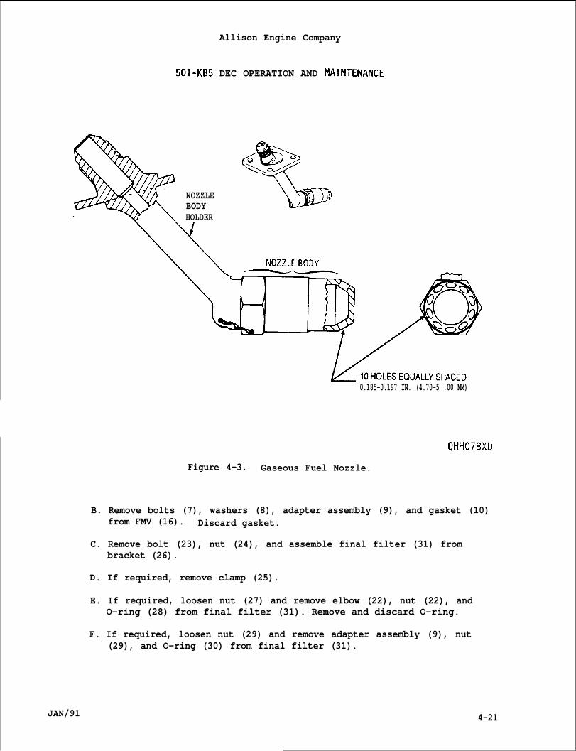
Allison Engine Company
501-KB5 DEC OPERATION AND MAINTENANLt
%
<0 “
NOZZLE :BODYHOLDER
0.185-0.197 IN. (4.70-5 .00 MM)
QHH078XD
Figure 4-3. Gaseous Fuel Nozzle.
B. Remove bolts (7), washers (8), adapter assembly (9), and gasket (10)from FMV (16). Discard gasket.
C. Remove bolt (23), nut (24), and assemble final filter (31) frombracket (26).
D. If required, remove clamp (25).
E. If required, loosen nut (27) and remove elbow (22), nut (22), andO-ring (28) from final filter (31). Remove and discard O-ring.
F. If required, loosen nut (29) and remove adapter assembly (9), nut(29), and O-ring (30) from final filter (31).
JAN/91 4-21
Allison Engine Company
501-KB5 DEC OPERATION AND MAINTENANCE
4-22. Installation.
A.
B.
c.
D.
E.
F.
If required, install nut (29, Figure 4-2) and O-ring (30) on adapterassembly (9). Install adapter assembly in final filter (31). Do nottighten nut (29).
If required, install nut (27) and O-ring (28) on elbow (22). Insta’elbow in final filter (31). Do not tighten nut (27).
Install assembled final filter (31) and clamp (25) to bracket (26)and secure with nut (24) and bolt (23). Do not tighten nut (24).
Install gasket (10) and adapter assembly (9) to FMV (16). Securewith bolts (7) and washers (8). Torque bolts to 70-85 lb in.(8.0-9.6 N“m) and lockwire bolts.
Torque nut (24) to37-42 lb in. (4.2-4.7 N-m) and tighten nut (29).
Install fuel supply hose (21) to elbow (22), aligning elbow asrequired. Torque hose coupling nut to 1200-1500-lb in. or 100 -125lbft. (135.6-169.4 N”m). Tighten nut (27).
4-23. FUEL MANIFOLD AND HOSES.
4-24. Descri~tion and OReration.
A. The fuel manifold supplies gaseous fuel from the FMV to the fuelmanifold hoses.
B. The fuel manifold hoses distribute gaseous fuel from the fuelmanifold to the fuel nozzles.
4-25. Removal.
NOTE
Record position of each fuel manifold hose for installation.
A. Remove fuel manifold hoses (20, Figure 4-2) from fuel nozzles (19)and fuel manifold (3).
B. Remove fuel manifold (3) as follows:
1. Remove bolts (2) and gasket (4) from FMV (16). Discard gasket.
2. Remove manifold test cap (32).
3. Remove nut (33), nut (34), bolt (35), clamp (36), and bracket(37) .
1
4-22 JAN/91
Allison Engine Company
501-KB5 DEC OPERATION AND MAINTENANCE
C. If reauired, remove bolts (38), burner drain valve covers (39), and. , .gaskets (40). Discard gasket~~
4-26. Installation.
A. If required, install gaskets (40, Figure 4-2),burner dracovers (39), and secure with bolts (38) with Ablube, MILapplied. Torque bolts to 70-85 lb in. (8.0-9.6 Nom) andbolts.
B. If required, install fuel manifold (3) as follows:
1. Install clamD (36) on fuel manifold (31 and secure to
n valveL-25681,lockwire
bracket {371with bolt (3S) ’and nut (34). Torque’nbt to 37-42 lb in. (4.2-4.7’Nom).
2. Install manifold test cap (32) and torque to 105-115 lb in,(11.9 -12.9 N-m).
3. Install fuel manifold (3) and gasket (4) to FMV (16) and securewith bolts (2). Torque bolts to 70-75 lb in. (8.0-9.6 Nom) andlockwire bolts.
4. Install bracket (37) to engine and secure with nut (33). Torquenut to 74-89 lb in. (8.4-10.0 Nom).
4-27. GASEOUS FUEL WATER INJECTION.
4-28. Descri~tion and O~eration.
A. Water injection is an option used to cool the combustion flametemperature of the engine reducing exhaust emissions.
B. Requirements for the water injection is a packaged water injectionsupply system, a check valve, and water injection connection. Thefuel nozzles will be changed to the dual fuel nozzles (Ref. Figure4-4) .
C. For maintenance on the packaged water injection supply system referto original equipment manufacturer (OEM) manual.
4-29. Dual Fuel Nozzle.
4-30. Description and Operation.
A. The dual fuel nozzle used for gaseous fuel water injection is thesame dual fuel nozzle used for liquid fuel water injection and dualfuel (gaseous and liquid) systems.
JAN/91 4-23
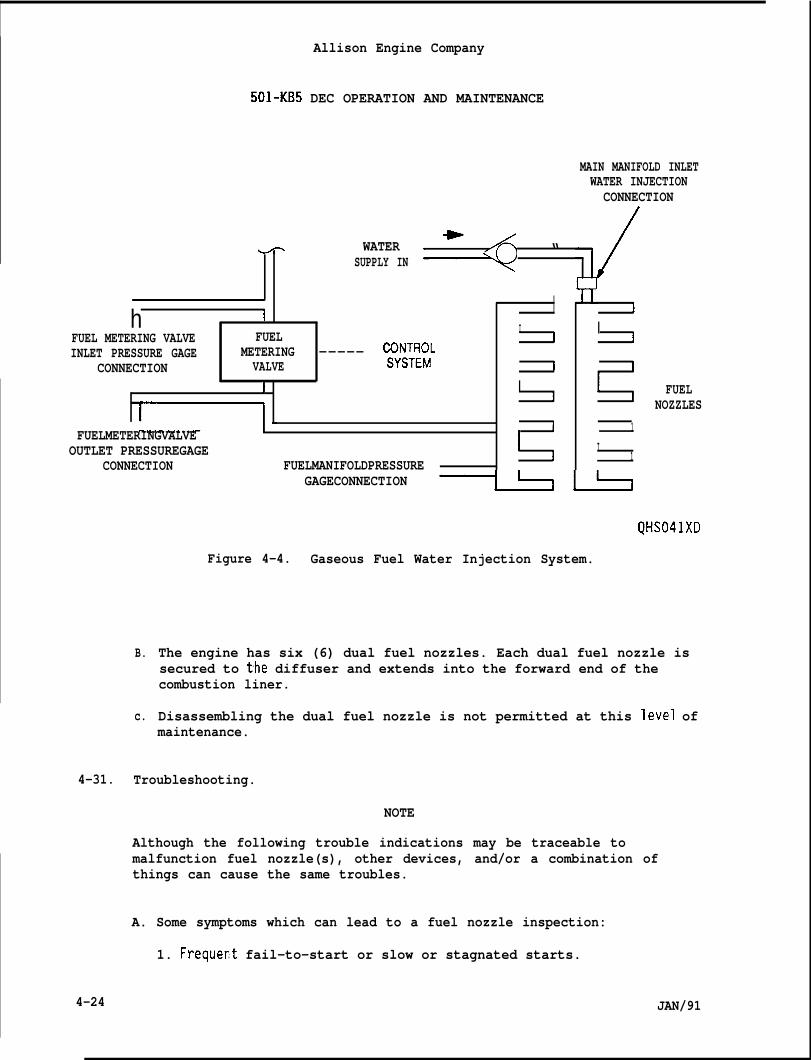
IAllison Engine Company
501-KB5 DEC OPERATION AND MAINTENANCE
MAIN MANIFOLD INLETWATER INJECTIONCONNECTION
m WATER =+ “SUPPLY IN
h I IFUEL METERING VALVE FUEL I
II I
INLET PRESSURE GAGE METERING ----- y:;;CONNECTION VALVE i 1
J I I
~1 -I [
FUELMETERINGVALVE 1 1
OUTLET PRESSUREGAGE I ICONNECTION FUELMANIFOLDPRESSURE I 1
FUELNOZZLES
GAGECONNECTION ~ k
QHS041XD
Figure 4-4. Gaseous Fuel Water Injection System.
B.
c.
The engine has six (6) dual fuel nozzles. Each dual fuel nozzle issecured to the diffuser and extends into the forward end of thecombustion liner.
Disassembling the dual fuel nozzle is not permitted at this level ofmaintenance.
4-31. Troubleshooting.
NOTE
Although the following trouble indications may be traceable tomalfunction fuel nozzle(s), other devices, and/or a combination ofthings can cause the same troubles.
A. Some symptoms which can lead to a fuel nozzle inspection:
1. Frequer,t fail-to-start or slow or stagnated starts.
4-24 JAN/91
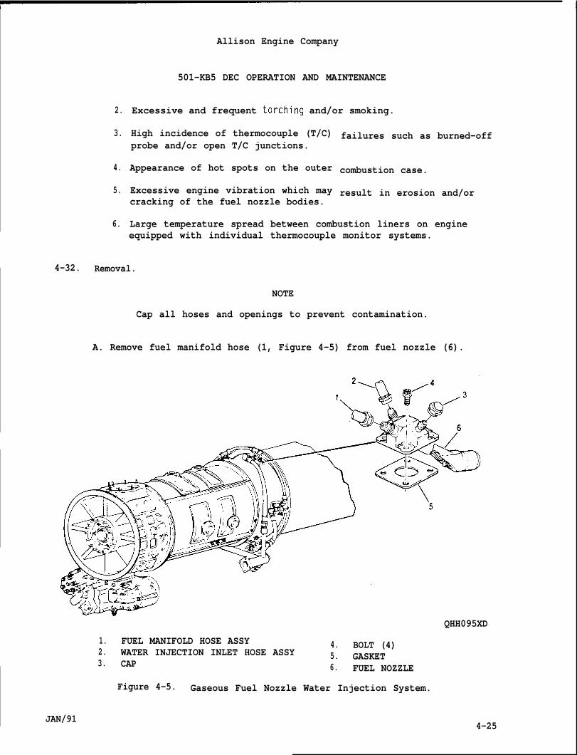
2.
3.
4.
5.
6.
Allison Engine Company
501-KB5 DEC OPERATION AND MAINTENANCE
Excessive and frequent torch-ing and/or smoking.
High incidence of thermocouple (T/C)probe and/or open T/C junctions.
Appearance of hot spots on the outer
Excessive engine vibration which maycracking of the fuel nozzle bodies.
failures such as burned-off
combustion case.
result in erosion and/or
Large temperature spread between combustion liners on engineequipped with individual thermocouple monitor systems.
4-32. Removal.
NOTE
Cap all hoses and openings to prevent contamination.
A. Remove fuel manifold hose (1, Figure 4-5) from fuel nozzle (6).
JAN/91
QHH095XD
1. FUEL MANIFOLD HOSE ASSY 4. BOLT (4)2. WATER INJECTION INLET HOSE ASSY 5. GASKET3. CAP 6. FUEL NOZZLE
Figure 4-5. Gaseous Fuel Nozzle Water Injection System.
4-25
Allison Engine Company
—..—501-KB5 DEC OPERATION AND MAINTENANCE
B. Remove water injection inlet hose (2) from fuel nozzle’s (6) maininlet port,
C. Remove bolts (4) and carefully remove fuel nozzle (6) and gasket(5). Discard gasket.
D. Repeat Steps A., B., and C. to required fuel nozzle(s) to be removed.
4-33. Inspection.
A.
B.
c.
D.
E.
Inspect for obvious physical damage such as metal deterioration(burns, erosion, corrosion) and cracks in the fuel nozzle body holderand body, Damage which affects the structural integrity of the fuelnozzle and/or which disturbs gas flow, is unacceptable.
Cracks between the jet holes or erosion of the holes is unacceptable.
Inspect the flame plated coating on the wear surface of the fuelnozzle body. Wear is permitted if the coating is not worn through tothe base metal at any place along the axial wear surface of the body.
Inspect for clogged passages and jet holes.
Inspect for carbon deposits. If they disturb the gas path in anyway,they will need to be removed.
4-34. Cleaning.
CAUTION
DO NOT USE A METHOD WHICH WILL REMOVE THE FLAME-PLATED ALUMINUM OXIDECOATING. AVOID CAUSTIC (BASE/HYDROXIDE) CLEANING SOLUTIONS.
NOTE
In order to ascertain the amount of damage, cleaning may have toprecede inspection.
A. Use light pressure with a soft cloth and petroleum solvent. Ifnecessary, use a carbon solvent.
B. Dry with filtered compressed air.
CAUTION
DO NOTHING WHICH WOULD INCREASE THE HOLE SIZE. IF HOSE SIZE ISINCREASED, REPLACE THE FUEL NOZZLE.
4-26 JAN/91
Allison Engine Company
501-KB5 DEC OPERATION AND MAINTENANCE
C. Assure that the spray orifices (jet holes) are open. If necessary,use an appropriate size probe to clean the orifices, such as a copperknife or wire. Hold fuel nozzle in such a position that scrapingsfall clear and not into the fuel nozzle.
D. Dry filtered compressed air may be blown through the fuel nozzlesinlet fuel connections to assure the fuel passages are cleared.
4-35. Installation.
A.
B.
c.
D.
E.
Apply Ablube, MIL-L-25681, to threads of bolts (4, Figure 4-5).
Install gasket (5) and carefully install fuel nozzle (6) and securewith bolts (4). Torque bolts to 70-85 lb in. (7.9-9.6 Nom).Lockwire bolts.
Install water injection inlet hose (2) to fuel nozzle (6). Torquehose coupling nut to 200-250 lb in. (22.6-28.2 Nom) and lockwire.
Install fuel manifold hose (1) to fuel nozzle (6). Torque hosecoupling nut to 325-400 lb in. (36.72-45.19 N-m) and lockwire.
If required, install cap (3) and torque to 80-120 lb in. (9.0-13.5N-m). Lockwire cap.
4-36. SINGLE ENTRY LIQUID FUEL SYSTEM.
4-37. DESCRIPTION.
A. The single entry fuel system consists of all the components necessaryto receive fuel, boost it to the necessary pressure, and supply it inthe necessary metered volume and pressure to the combustion sectionof the engine.
B. Components of the fuel system are mounted in various locations on ornear the engine. The components are:
;:3.4.5.6.7.8.
1::11.12.
JAN/91
Fuel pump.Low pressure (LP) fuel filter with differential pressure switch.High pressure (HP) fuel filter.Fuel pump paralleling valve.Pressure relief valve.Fuel metering valve (FMV).Fuel shutoff valve.Fuel manifold.Fuel nozzles.Manifold drain valve.Burner drain valves.Lines and hoses.
4-27
Allison Engine Company
501-KB5 DEC OPERATION AND MAINTENANCE
C. An optional water injection may be installed, the fuel system isconverted to a dual entry fuel-system usingParagraph 4-94).
D. The approved fuels are listed in Table 4-1.
4-38. OPERATION.
A. During engine operation, liquid fuel enterspasses into the boost (centrifugal) elementpump. The boosted fuel flows from the fuel
dual fuel no~zles (Ref.
the fuel pump inlet andof the engine driven fuelt)umD to the LP fuel
filter then returns through internal passage: o; the HP fuel--filterto the gear elements of the fuel pump. The two gear elements of thefuel pump normally operate in series but operate in parallel forstarting. The high pressure (HP) fuel flows from the fuel pumpthrough the HP fuel filter. The pressure relief valve limits fuelpressure to 500 psi (3445 kPa) and will bypass the excess fuel backto the fuel pump inlet. The HP fuel is delivered to the fuelmetering valve (FMV). The FMV, by direction of the control system,meters the fuel required and bypasses the remainder fuel. Bypass fuelis returned to the fuel pump inlet through a passage in the HP fuelfilter. The metered fuel passes through the fuel shutoff valve to themanifold drain valve and directs the metered fuel to the fuelmanifold which distributes the fuel to the six fuel nozzles. Aschematic of the single entry liquid fuel system is shown in Figure4-6.
B. The engine is shutdown by closing the fuel shutoff valve. Fuelremaining in the fuel nozzles, fuel manifold, and combustion sectionis automatically drained from the engine by the opening of themanifold drain valves and burner drain valves.
CAUTION
FUEL DRAINAGE ACCUMULATION IS APPROXIMATELY 8.0 GALLONS (30.4 LITERS)PER 100 ENGINE STARTS. THE VENTED DRAIN COLLECTOR TANK SHOULD NOT BEALLOWED TO FILL AS THIS RESTRICTS THE CORRECT FUNCTIONING OF THE FUELMANIFOLD DRAIN SYSTEM.
4-39. FUEL PUMP.
4-40. Descri~tion and ODeration.
A. The engine driven, dual element fuel pump is flange mounted on theright rear drive pad of the accessory drive gearbox. The fuel pumpconsists of an impeller type centrifugal boost pump with bypass valveand a dual-element (primary and secondary) gear type pump. Thedesign of the fuel pump is such that the capacity of the primaryelement is 10 percent more than that of the secondary element.
4-28 JAN/91
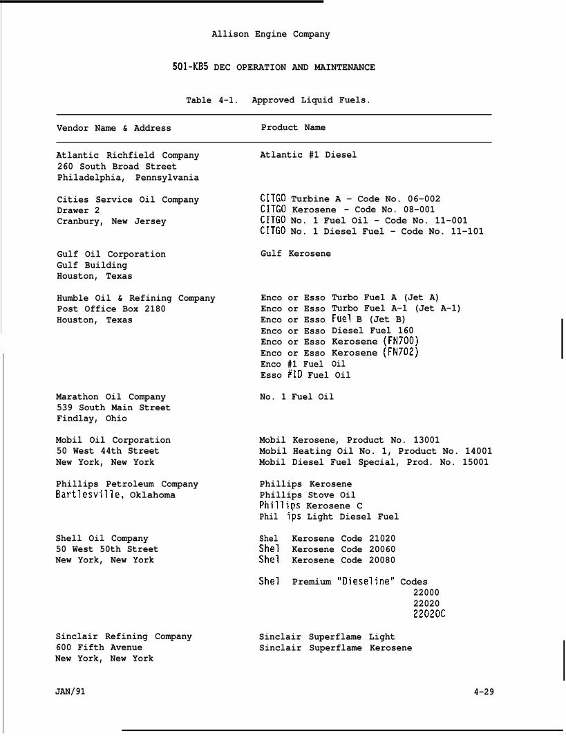
Allison Engine Company
501-KB5 DEC OPERATION AND MAINTENANCE
Table 4-1. Approved Liquid Fuels.
Vendor Name & Address Product Name
Atlantic Richfield Company260 South Broad StreetPhiladelphia, Pennsylvania
Cities Service Oil CompanyDrawer 2Cranbury, New Jersey
Gulf Oil CorporationGulf BuildingHouston, Texas
Humble Oil & Refining CompanyPost Office Box 2180Houston, Texas
Marathon Oil Company539 South Main StreetFindlay, Ohio
Mobil Oil Corporation50 West 44th StreetNew York, New York
Phillips Petroleum CompanyBartlesville, Oklahoma
Shell Oil Company50 West 50th StreetNew York, New York
Sinclair Refining Company600 Fifth AvenueNew York, New York
JAN/91
Atlantic #1 Diesel
CITGO Turbine A - Code No. 06-002CITGO Kerosene - Code No. 08-001CITGO No. 1 Fuel Oil - Code No. 11-001CITGO No. 1 Diesel Fuel - Code No. 11-101
Gulf Kerosene
Enco or EssoEnco or EssoEnco or EssoEnco or EssoEnco or EssoEnco or EssoEnco #1 Fuel
Turbo Fuel A (Jet A)Turbo Fuel A-1 (Jet A-1)Fuel B (Jet B)Diesel Fuel 160Kerosene (FN700)Kerosene (FN702)Oil
Esso #lD Fuel Oil
No. 1 Fuel Oil
Mobil Kerosene, Product No. 13001Mobil Heating Oil No. 1, Product No. 14001Mobil Diesel Fuel Special, Prod. No. 15001
Phillips KerosenePhillips Stove OilPhilliDs Kerosene CPhil
ShelShelShel
Shel
ips Light Diesel Fuel
Kerosene Code 21020Kerosene Code 20060Kerosene Code 20080
Premium “Dieseline” Codes220002202022020C
Sinclair Superflame LightSinclair Superflame Kerosene
4-29
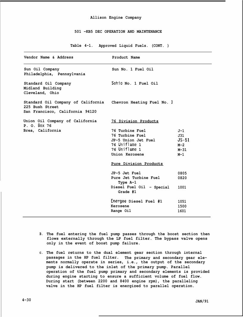
Allison Engine Company
501 -KB5 DEC OPERATION AND MAINTENANCE
Table 4-1. Approved Liquid Fuels. (CONT. )
Vendor Name & Address Product Name
Sun Oil CompanyPhiladelphia, Pennsylvania
Standard Oil CompanyMidland BuildingCleveland, Ohio
Standard Oil Company of California225 Bush StreetSan Francisco, California 94120
Union Oil Company of CaliforniaP. O. BOX 76Brea, California
Sun No. 1 Fuel Oil
Sohio No. 1 Fuel Oil
Chevron Heating Fuel No. 1
76 Division Products
76 Turbine Fuel76 Turbine FuelJP-5 Union Jet Fuel76 Uniflame 176 Uniflame 1Union Kerosene
Pure Division Products
JP-5 Jet FuelPure Jet Turbine Fuel
Type A-1Diesel Fuel Oil - Special
Grade #1
Energee Diesel Fuel #1KeroseneRange Oil
J-1J31JS-51M-2M-31M-1
08050820
1001
105115001601
B.
c.
4-30
The fuel entering the fuel pump passes through the boost section thenflows externally through the LP fuel filter. The bypass valve opensonly in the event of boost pump failure.
The fuel returns to the dual element gear section through internalpassages in the HP fuel filter. The primary and secondary gear ele-ments normally operate in series, i.e., the output of the secondarypump is delivered to the inlet of the primary pump. Paralleloperation of the fuel pump primary and secondary elements is providedduring engine starting to ensure a sufficient volume of fuel flow.During start (between 2200 and 8400 engine rpm), the parallelingvalve in the HP fuel filter is energized to parallel operation.
JAN/91
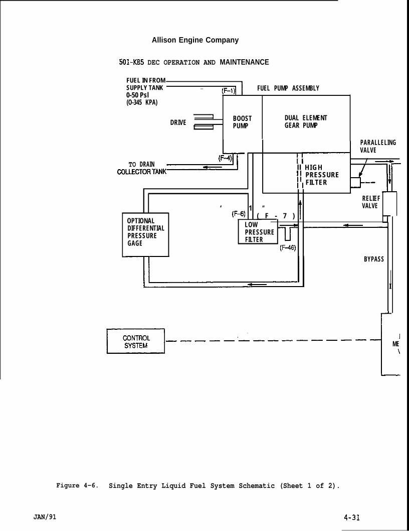
Allison Engine Company
501-KB5 DEC OPERATION AND MAINTENANCE
FUEL IN FROMSUPPLY TANK — (F-1)1 FUEL PUMP ASSEMBLY0-50 Psl(O-345 KPA)
JDRIVE
tBOOST DUAL ELEMENT
1 PUMP GEAR PUMP
TO DRAIN >
PARALLELINGVALVE
I l—IIII H I G H
/ ~
I I PRESSURE‘ ‘ FILTERII [
‘ 1 “t
RELIEFVALVE
OPTIONAL(F+) ( F - 7 )
DIFFERENTIAL LOW
PRESSURE PRESSURE
GAGE FILTER(F+
BYPASS
I
R=l-------------- $MEI
Figure 4-6. Single Entry Liquid Fuel System Schematic (Sheet 1 of 2).
JAN/91
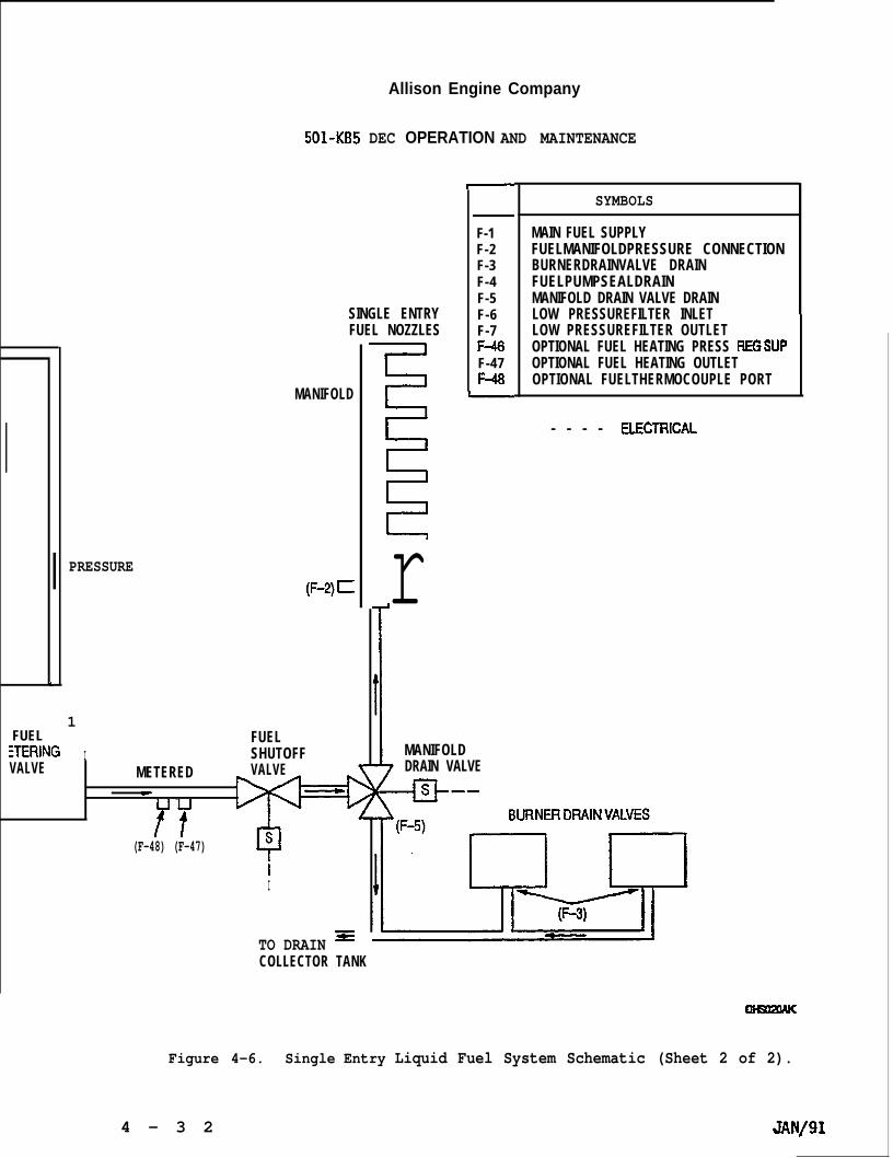
.
FUEL
Allison Engine Company
501-KB5 DEC OPERATION AND MAINTENANCE
SINGLE ENTRYFUEL NOZZLES
MANIFOLD
PRESSURE(F-2)~
1
:TERING IFUELSHUTOFF
VALVE METERED VALVEeUurt
(F-48) (F-47)
iI
TO DRAIN =
F-1F-2F-3F-4F-5F-6F-7F+F-47
rL MANIFOLD
DRAIN VALVE
@--
SYMBOLS
MAIN FUEL SUPPLYFUELMANIFOLDPRESSURE CONNECTIONBURNERDRAINVALVE DRAINFUELPUMPSEALDRAINMANIFOLD DRAIN VALVE DRAINLOW PRESSUREFILTER INLETLOW PRESSUREFILTER OUTLETOPTIONAL FUEL HEATING PRESS REGSUPOPTIONAL FUEL HEATING OUTLETOPTIONAL FUELTHERMOCOUPLE PORT
- - - - ELECITllCAL
COLLECTOR TANK
Figure 4-6. Single Entry Liquid Fuel System Schematic (Sheet 2 of 2).
4 - 3 2 JAN/91
Allison Engine Company
501-KB5 DEC OPERATION AND MAINTENANCE
D. If either fuel pump element (primary or secondary) should fail, theremaining element is capable of providing sufficient fuel flow andpressure for normal operation, however, starting may be affected.
4-41. Removal.NOTE
The fuel pump with the HP fuel filter is removed and installed as acomplete assembly.
A. Provide containers to catch fuel drainage.
NOTE
Make sure fuel and electrical systems are OFF and remain OFF untilinstallation is completed.
B.
c.
D.
E.
F,
G.
H.
I.
J.
K.
L.
Remove inlet fuel hose (Ref. OEM’S Manual).
Remove LP filter return hose (6, Figure 4-7) and bypass return hose(7) from tee (22).
Remove HP outlet
Remove LP filter
Remove fuel pump
Cap all openings
hose (8) from elbow (21).
outlet hose (9) from union (14).
seal drain hose (10) from elbow (11).
to prevent contamination.
Remove paralleling valve electrical connector.
Remove the washers (3) and nuts (2), and slide the assembled fuelpump and HP fuel filter rearward and off as a complete assembly.
Remove and discard the gasket (4) and O-ring (5).
If fuel pump (1) and/or HP fuel filter (16) need to be separated,remove the short bolts (17), long bolts (18) and washers (19).Separate fuel pump and HP fuel filter. Remove and discard O-rings(20) .
NOTE
Record position of elbow for installation.
If the fuel pump is to be replaced, remove union (14), elbow (11),nut (13), and O-rings (12 and 15) for installation on the replacementunit. Discard O-rings.
JAN/91 4-33
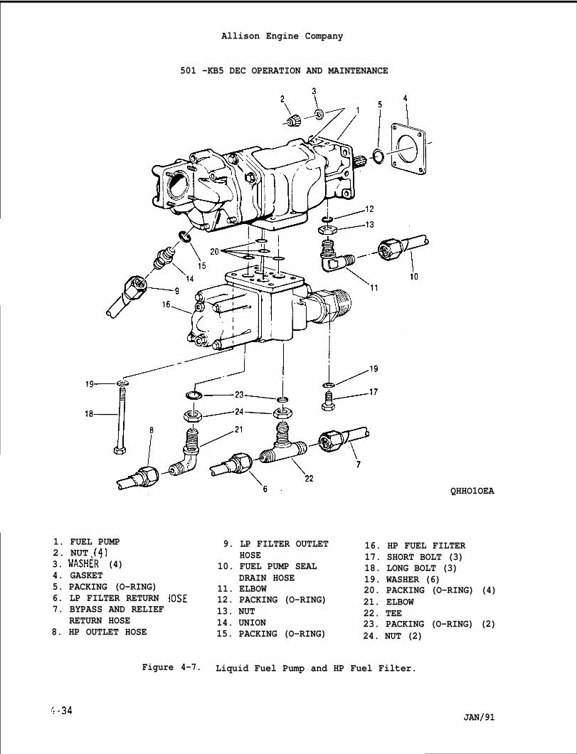
Allison Engine Company
501 -KB5 DEC OPERATION AND MAINTENANCE
QHHO1OEA
1. FUEL PUMP2. NUT (4)3. WASHiR’ (4)4. GASKET5. PACKING (O-RING)6. LP FILTER RETURN IOSE7. BYPASS AND RELIEF
RETURN HOSE8. HP OUTLET HOSE
9. LP FILTER OUTLETHOSE
10. FUEL PUMP SEALDRAIN HOSE
11. ELBOW12. PACKING (O-RING)13. NUT14. UNION15. PACKING (O-RING)
16. HP FUEL FILTER17. SHORT BOLT (3)18. LONG BOLT (3)19. WASHER (6)20. PACKING (O-RING) (4)21. ELBOW22. TEE23. PACKING (O-RING) (2)24. NUT (2)
Figure 4-7. Liquid Fuel Pump and HP Fuel Filter.
L-34 JAN/91
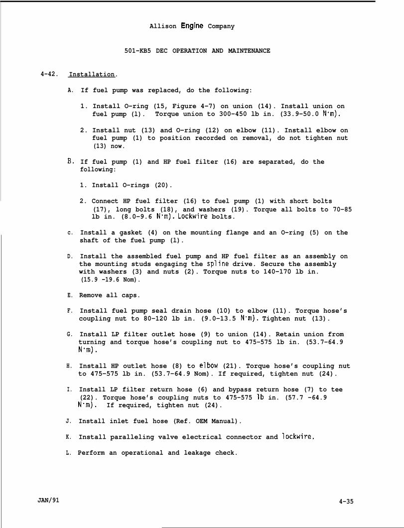
Allison Engine Company
501-KB5 DEC OPERATION AND MAINTENANCE
4-42. Installation.
A.
B.
c.
D.
E.
F.
G.
H.
I.
J.
K.
L.
JAN/91
If fuel pump was replaced, do the following:
1. Install O-ring (15, Figure 4-7) on union (14). Install union onfuel pump (l). Torque union to 300-450 lb in. (33.9-50.0 N“m).
2. Install nut (13) and O-ring (12) on elbow (11). Install elbow onfuel pump (1) to position recorded on removal, do not tighten nut(13) now.
If fuel pump (1) and HP fuel filter (16) are separated, do thefollowing:
1. Install O-rings (20).
2. Connect HP fuel filter (16) to fuel pump (1) with short bolts(17), long bolts (18), and washers (19). Torque all bolts to 70-85lb in. (8.0-9.6 N’m). Lockwire bolts.
Install a gasket (4) on the mounting flange and an O-ring (5) on theshaft of the fuel pump (l).
Install the assembled fuel pump and HP fuel filter as an assembly onthe mounting studs engaging the spline drive. Secure the assemblywith washers (3) and nuts (2). Torque nuts to 140-170 lb in.(15.9 -19.6 Nom).
Remove all caps.
Install fuel pump seal drain hose (10) to elbow (11). Torque hose’scoupling nut to 80-120 lb in. (9.0-13.5 N“m). Tighten nut (13).
Install LP filter outlet hose (9) to union (14). Retain union fromturning and torque hose’s coupling nut to 475-575 lb in. (53.7-64.9Nom).
Install HP outlet hose (8) to elbow (21). Torque hose’s coupling nutto 475-575 lb in. (53.7-64.9 Nom). If required, tighten nut (24).
Install LP filter return hose (6) and bypass return hose (7) to tee(22). Torque hose’s coupling nuts to 475-575 lb in. (57.7 -64.9N-m). If required, tighten nut (24).
Install inlet fuel hose (Ref. OEM Manual).
Install paralleling valve electrical connector and lockwire.
Perform an operational and leakage check.
4-35

1 -1
Allison Engine Company
501-KB5 DEC OPERATION AND MAINTENANCE
4-43. Troubleshootinq.
There is no repair
NOTE
allowed for the fuel pump at this maintenance level.
A. Drainage of fuel from the fuel pump seal drain line indicates thefuel pump shaft seal is leaking. Remove and replace the fuel pump.
B. Oil drainage from the seal drain indicates the seal in the accessorydrive gearbox for the fuel pump shaft is leaking. Refer to Section9, Starter and Accessory Drive Gearbox, for replacement of the oilseal.
C. Internal failure of one of the gear elements in the fuel pump isindicated by slow cool starting without a temperature spike when thefuel pump flow is shifted from parallel to series at about 9200 GGrpm. Remove and replace the fuel pump.
4-44. HIGH PRESSURE (HP) FUEL FILTER.
4-45. Descrir)tion and O~eration.
A.
B.
c.
D.
The HP fuel filter is attached to the bottom of the dual element fuelpump; fuel passages within the mounting flange connect the twounits. The HP fuel filter consists of the housing, filter element,bypass valve, and two check valves. The paralleling valve mounts onthe HP fuel filter body.
The filter element is a 17 metal disk type, a 33 micron filter and isremovable for cleaning and servicing. The bypass valve permits acontinuous flow of fuel to the engine in the event the filter elementbecomes clogged. Operating pressure of the bypass valve is 120 ~10psi (828~69 kPa).
Should either gear element fail, the two check valves permit engineoperation from the other gear element.
A paralleling valve, when closed, permits the combininq of the outputof”both gear-type fuel pump elements during starts; wh;n opened, itprovides series operation for normal engine operation.
4-46. Removal.NOTE
Make sure fuel and electrical systems are OFF and remain OFF untilinstallation is completed.
A. Remove the fuel pump and HP fuel filter as an assembly. Refer toParagraph 4-41.
4-36 JAN/91
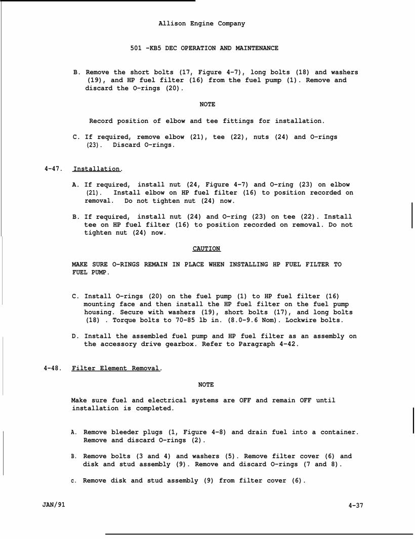
Allison Engine Company
501 -KB5 DEC OPERATION AND MAINTENANCE
B. Remove the short bolts (17, Figure 4-7), long bolts (18) and washers(19), and HP fuel filter (16) from the fuel pump (1). Remove anddiscard the O-rings (20).
NOTE
Record position of elbow and tee fittings for installation.
C. If required, remove elbow (21), tee (22), nuts (24) and O-rings(23). Discard O-rings.
4-47. Installation.
A. If required, install nut (24, Figure 4-7) and O-ring (23) on elbow(21). Install elbow on HP fuel filter (16) to position recorded onremoval. Do not tighten nut (24) now.
B. If required, install nut (24) and O-ring (23) on tee (22). Installtee on HP fuel filter (16) to position recorded on removal. Do nottighten nut (24) now.
CAUTION
MAKE SURE O-RINGS REMAIN IN PLACE WHEN INSTALLING HP FUEL FILTER TOFUEL PUMP.
C. Install O-rings (20) on the fuel pump (1) to HP fuel filter (16)mounting face and then install the HP fuel filter on the fuel pumphousing. Secure with washers (19), short bolts (17), and long bolts(18) . Torque bolts to 70-85 lb in. (8.0-9.6 Nom). Lockwire bolts.
D. Install the assembled fuel pump and HP fuel filter as an assembly onthe accessory drive gearbox. Refer to Paragraph 4-42.
4-48. Filter Element Removal.
NOTE
Make sure fuel and electrical systems are OFF and remain OFF untilinstallation is completed.
A.
B.
c.
JAN/91
Remove bleeder plugs (1, Figure 4-8) and drain fuel into a container.Remove and discard O-rings (2).
Remove bolts (3 and 4) and washers (5). Remove filter cover (6) anddisk and stud assembly (9). Remove and discard O-rings (7 and 8).
Remove disk and stud assembly (9) from filter cover (6).
4-37
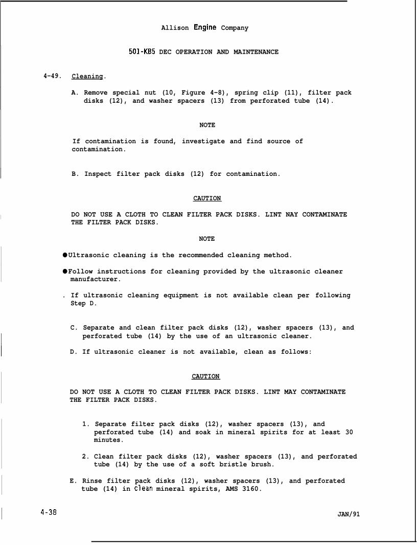
Allison Engine Company
501-KB5 DEC OPERATION AND MAINTENANCE
4-49. Cleaning.
A. Remove special nut (10, Figure 4-8), spring clip (11), filter packdisks (12), and washer spacers (13) from perforated tube (14).
NOTE
If contamination is found, investigate and find source ofcontamination.
1 B. Inspect filter pack disks (12) for contamination.
CAUTION
I DO NOT USE A CLOTH TO CLEAN FILTER PACK DISKS. LINT NAY CONTAMINATETHE FILTER PACK DISKS.
1 NOTE
● Ultrasonic cleaning is the recommended cleaning method.
● Follow instructions for cleaning provided by the ultrasonic cleanermanufacturer.
. If ultrasonic cleaning equipment is not available clean per followingStep D.
C. Separate and clean filter pack disks (12), washer spacers (13), and
1perforated tube (14) by the use of an ultrasonic cleaner.
~ D. If ultrasonic cleaner is not available, clean as follows:
CAUTION
DO NOT USE A CLOTH TO CLEAN FILTER PACK DISKS. LINT MAY CONTAMINATETHE FILTER PACK DISKS.
1. Separate filter pack disks (12), washer spacers (13), andperforated tube (14) and soak in mineral spirits for at least 30minutes.
2. Clean filter pack disks (12), washer spacers (13), and perforatedtube (14) by the use of a soft bristle brush.
E. Rinse filter pack disks (12), washer spacers (13), and perforatedtube (14) in clean mineral spirits, AMS 3160.
JAN/91
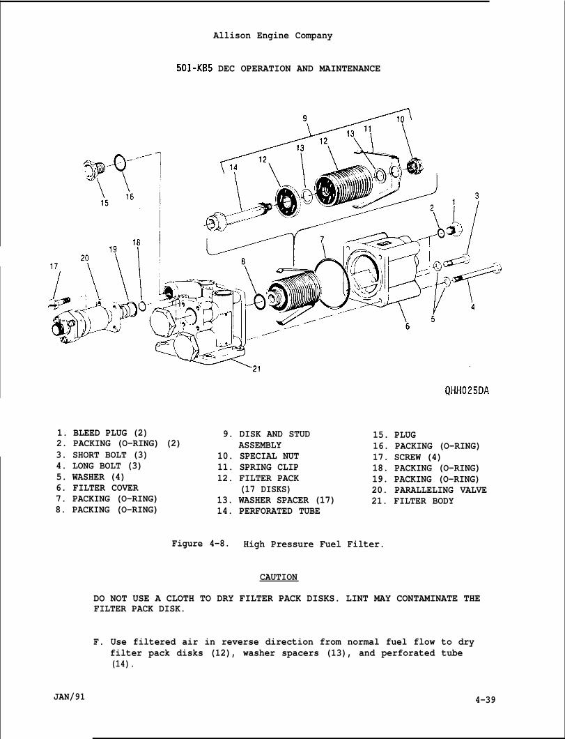
Allison Engine Company
501-KB5 DEC OPERATION AND MAINTENANCE
1. BLEED PLUG (2)2. PACKING (O-RING) (2)3. SHORT BOLT (3)4. LONG BOLT (3)5. WASHER (4)6. FILTER COVER7. PACKING (O-RING)8. PACKING (O-RING)
~HH025DA
9. DISK AND STUD 15. PLUGASSEMBLY 16. PACKING (O-RING)
10. SPECIAL NUT 17. SCREW (4)11. SPRING CLIP 18. PACKING (O-RING)12. FILTER PACK 19. PACKING (O-RING)
(17 DISKS) 20. PARALLELING VALVE13. WASHER SPACER (17) 21. FILTER BODY14. PERFORATED TUBE
Figure 4-8. High Pressure Fuel Filter.
CAUTION
DO NOT USE A CLOTH TO DRY FILTER PACK DISKS. LINT MAY CONTAMINATE THEFILTER PACK DISK.
F. Use filtered air in reverse direction from normal fuel flow to dryfilter pack disks (12), washer spacers (13), and perforated tube(14).
JAN/91 4-39
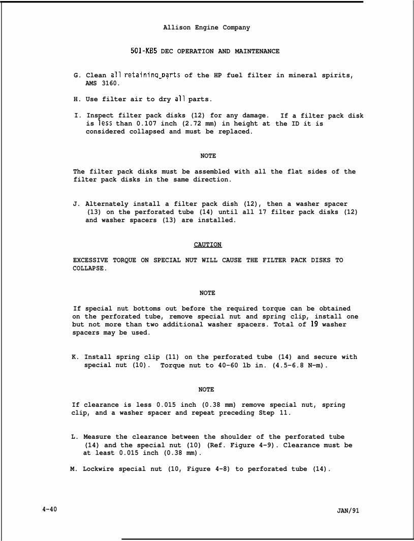
Allison Engine Company
501-KB5 DEC OPERATION AND MAINTENANCE
G. Clean all retainina Darts of the HP fuel filter in mineral spirits,- ,AMS 3160.
H. Use filter air to dry all parts.
I. Inspect filter pack disks (12) for any damage.is less than 0.107 inch (2.72 mm) in height atconsidered collapsed and must be replaced.
NOTE
If a filter pack diskthe ID it is
The filter pack disks must be assembled with all the flat sides of thefilter pack disks in the same direction.
J. Alternately install a filter pack dish (12), then a washer spacer(13) on the perforated tube (14) until all 17 filter pack disks (12)and washer spacers (13) are installed.
CAUTION
EXCESSIVE TORQUE ON SPECIAL NUT WILL CAUSE THE FILTER PACK DISKS TOCOLLAPSE.
NOTE
If special nut bottoms out before the required torque can be obtainedon the perforated tube, remove special nut and spring clip, install onebut not more than two additional washer spacers. Total of 19 washerspacers may be used.
K. Install spring clip (11) on the perforated tube (14) and secure withspecial nut (10). Torque nut to 40-60 lb in. (4.5-6.8 N-m).
NOTE
If clearance is less 0.015 inch (0.38 mm) remove special nut, springclip, and a washer spacer and repeat preceding Step 11.
L. Measure the clearance between the shoulder of the perforated tube(14) and the special nut (10) (Ref. Figure 4-9). Clearance must beat least 0.015 inch (0.38 mm).
4-40
M. Lockwire special nut (10, Figure 4-8) to perforated tube (14).
JAN/91
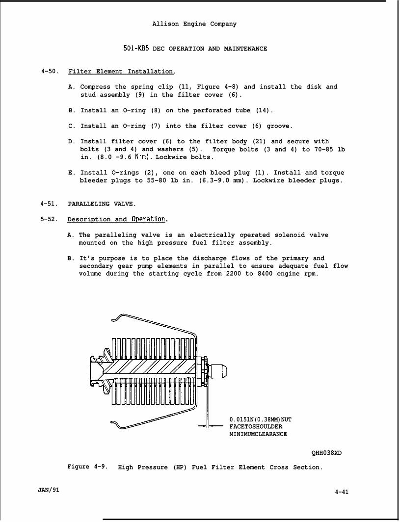
Allison Engine Company
501-KB5 DEC OPERATION AND MAINTENANCE
4-50. Filter Element Installation.
A. Compress the spring clip (11, Figure 4-8) and install the disk andstud assembly (9) in the filter cover (6).
B. Install an O-ring (8) on the perforated tube (14).
C. Install an O-ring (7) into the filter cover (6) groove.
D. Install filter cover (6) to the filter body (21) and secure withbolts (3 and 4) and washers (5). Torque bolts (3 and 4) to 70-85 lbin. (8.0 -9.6 N”m). Lockwire bolts.
E. Install O-rings (2), one on each bleed plug (l). Install and torquebleeder plugs to 55-80 lb in. (6.3-9.0 mm). Lockwire bleeder plugs.
4-51. PARALLELING VALVE.
5-52. Description and OReration.
A. The paralleling valve is an electrically operated solenoid valvemounted on the high pressure fuel filter assembly.
B. It’s purpose is to place the discharge flows of the primary andsecondary gear pump elements in parallel to ensure adequate fuel flowvolume during the starting cycle from 2200 to 8400 engine rpm.
S-IL 0.0151N(0.38MM)NUTFACETOSHOULDERMINIMUMCLEARANCE
QHH038XD
Figure 4-9. High Pressure (HP) Fuel Filter Element Cross Section.
JAN/91 4-41
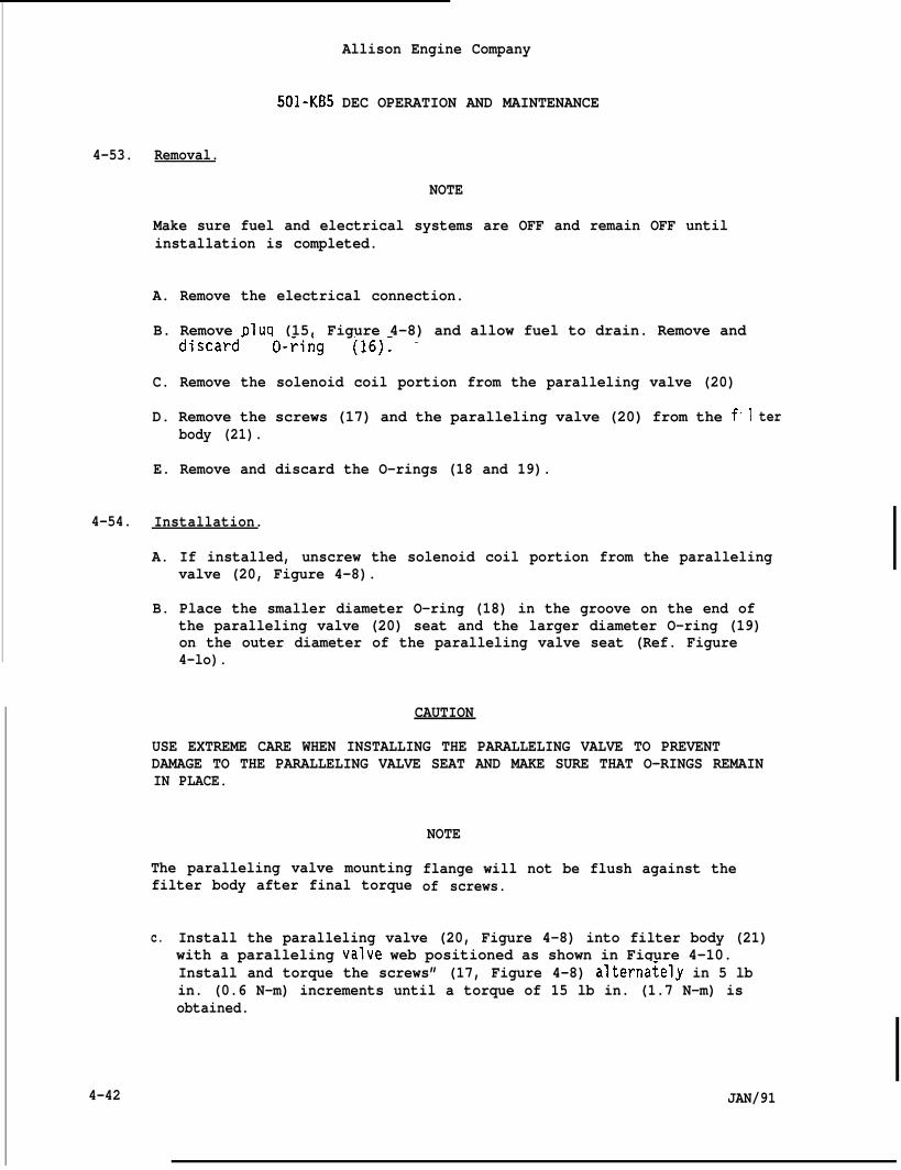
Allison Engine Company
501-KB5 DEC OPERATION AND MAINTENANCE
4-53. Removal.
NOTE
Make sure fuel and electrical systems are OFF and remain OFF untilinstallation is completed.
A. Remove the electrical connection.
B. Remove plug (15, Figure 4-8) and allow fuel to drain. Remove anddiscard” O-~ing (16): -
C. Remove the solenoid coil portion from the paralleling valve (20)
D. Remove the screws (17) and the paralleling valve (20) from the fbody (21).
E. Remove and discard the O-rings (18 and 19).
4-54. Installation.
1 ter
A. If installed, unscrew the solenoid coil portion from the parallelingvalve (20, Figure 4-8).
B. Place the smaller diameter O-ring (18) in the groove on the end ofthe paralleling valve (20) seat and the larger diameter O-ring (19)on the outer diameter of the paralleling valve seat (Ref. Figure4-lo).
CAUTION
USE EXTREME CARE WHEN INSTALLING THE PARALLELING VALVE TO PREVENTDAMAGE TO THE PARALLELING VALVE SEAT AND MAKE SURE THAT O-RINGS REMAININ PLACE.
NOTE
The paralleling valve mountingfilter body after final torque
flange will not be flush against theof screws.
c.
4-42
Install the paralleling valve (20, Figure 4-8) into filter body (21)with a paralleling valve web positioned as shown in Figure 4-10.Install and torque the screws” (17, Figure 4-8) alterna~ely in 5 lbin. (0.6 N-m) increments until a torque of 15 lb in. (1.7 N-m) isobtained.
JAN/91
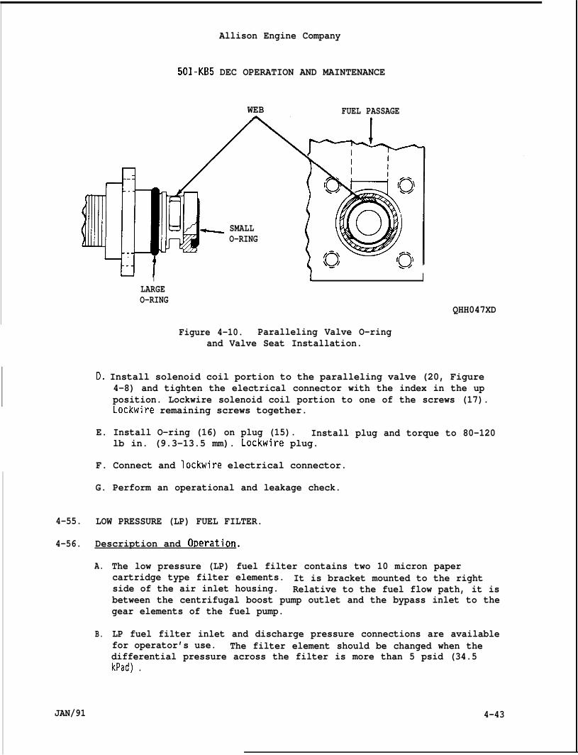
Allison Engine Company
501-KB5 DEC OPERATION AND MAINTENANCE
WEB FUEL PASSAGE
SMALLO-RING
I ( I
QHH047XD
LARGEO-RING
Figure 4-10. Paralleling Valve O-ringand Valve Seat Installation.
D. Install solenoid coil portion to the paralleling valve (20, Figure4-8) and tighten the electrical connector with the index in the upposition. Lockwire solenoid coil portion to one of the screws (17).
I Lockwire remaining screws together.
E. Install O-ring (16) on plug (15). Install plug and torque to 80-120lb in. (9.3-13.5 mm). Lockwire plug.
F. Connect and lockwire electrical connector.
G. Perform an operational and leakage check.
4-55. LOW PRESSURE (LP) FUEL FILTER.
4-56. Description and ODeration.
A.
B.
JAN/91
The low pressure (LP) fuel filter contains two 10 micron papercartridge type filter elements. It is bracket mounted to the rightside of the air inlet housing. Relative to the fuel flow path, it isbetween the centrifugal boost pump outlet and the bypass inlet to thegear elements of the fuel pump.
LP fuel filter inlet and discharge pressure connections are availablefor operator’s use. The filter element should be changed when thedifferential pressure across the filter is more than 5 psid (34.5kPad) .
4-43
1
I IAllison Engine Company
501-KB5 DEC OPERATION AND MAINTENANCE
4-57. Fuel Filter Elements Removal.
NOTE
Make sure fuel and electrical systems are OFF and remain OFF untilinstallation is completed.
A. Remove drain plug (2, Figure 4-11) from bar (15) and permit fuel todrain from fuel filter into a container. Remove and discard O-ring(3).
B. Remove case and bar assembly (7) by loosening bar (15).
C. Remove filter elements (5) from case and bar assembly (7).
D. Inspect filter elements (5) for evidence of fuel contamination.
E. Remove element support plate (6) from between the filter elements(5). Discard filter elements.
F. Remove and discard O-ring (4) from head assembly (l).
G. Disassemble case and bar assembly (7) as follows:
1.
2.
3.
4.
Install spring depressor, 6796975, on bar (15) and tighten handknob until element support spring (11) is depressed (Ref. Figure4-12).
Remove retaining ring (8, Figure 4-11) using pliers, 6796974 (Ref.Figure 4-13).
Remove support washer (9, Figure 4-11), element support plate(10), element support spring (11) and bar (15) from case (16) byremoving spring depressor, 6796975.
Remove and discard O-rings (12 and 13) and gasket (14) from bar.
H. Clean all parts in an approved cleaning solvent such as Federal SpecP-D-680-2.
4-58. Fuel Filter Elements Installation.
A. Assemble case and bar assembly (7, Figure 4-11) as follows:
1. Install
2. Apply athreads
3. Install(16).
4-44
gasket (14) on bar (15).
light coat of clean engine lubricating oil to the bar (15)and O-rings (12 and 13).
O-rings (12 and 13) on bar and insert bar (15) in the case
JAN/91
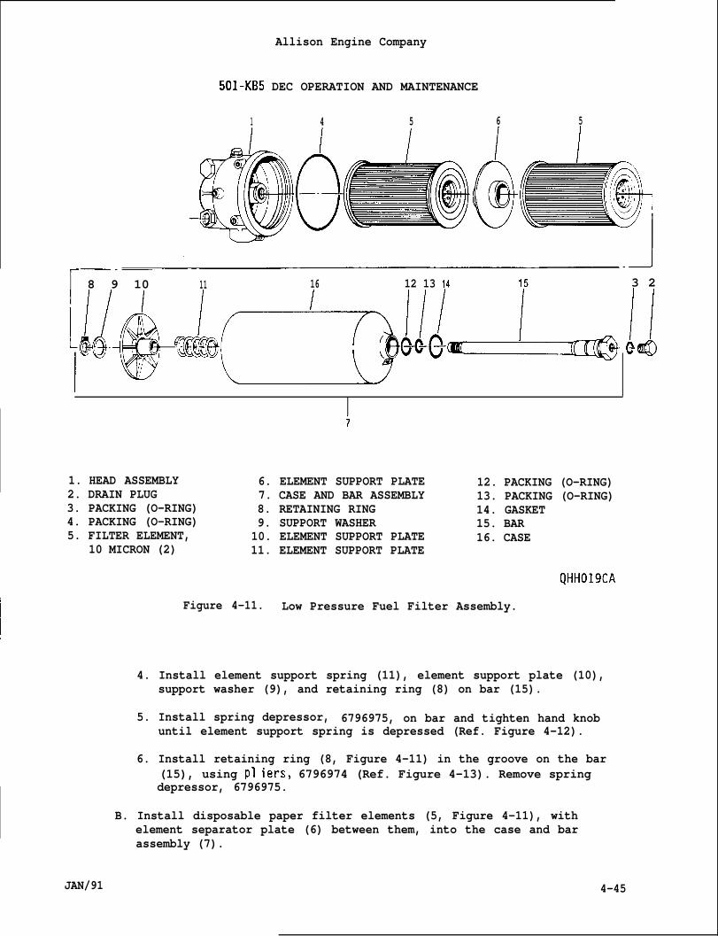
Allison Engine Company
501-KB5 DEC OPERATION AND MAINTENANCE
1 4 5 6 5
I
8 9 10 11 16 12 13 14 3 2
HWI!@
7
1. HEAD ASSEMBLY 6. ELEMENT SUPPORT PLATE 12. PACKING (O-RING)2. DRAIN PLUG 7. CASE AND BAR ASSEMBLY 13. PACKING (O-RING)3. PACKING (O-RING) 8. RETAINING RING 14. GASKET4. PACKING (O-RING) 9. SUPPORT WASHER 15. BAR5. FILTER ELEMENT, 10. ELEMENT SUPPORT PLATE 16. CASE
10 MICRON (2) 11. ELEMENT SUPPORT PLATE
QHH019CA
Figure 4-11. Low Pressure Fuel Filter Assembly.
4. Install element support spring (11), element support plate (10),support washer (9), and retaining ring (8) on bar (15).
5. Install spring depressor, 6796975, on bar and tighten hand knobuntil element support spring is depressed (Ref. Figure 4-12).
6. Install retaining ring (8, Figure 4-11) in the groove on the bar(15), using PI iers, 6796974 (Ref. Figure 4-13). Remove springdepressor, 6796975.
B. Install disposable paper filter elements (5, Figure 4-11), withelement separator plate (6) between them, into the case and barassembly (7).
JAN/91 4-45
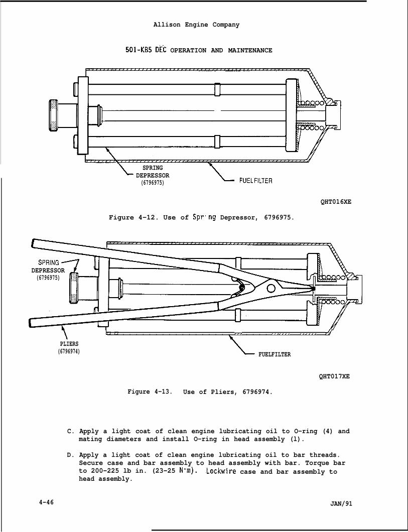
Allison Engine Company
501-KB5 DEC OPERATION AND MAINTENANCE
IJ
,y,.:
L SPRINGDEPRESSOR(6796975)
Figure 4-12. Use of Spr
\
ng
= FUEL FILTER
Depressor, 6796975.
QHT016XE
DEPRESSOR(6796975)
\b. .z . . . . . . . . . . . . . . . . . ..z . . . . .E. ..r, . . . . . . . . ..rr.r . . . . . . . 7?4
PLIERS(6796974) FUELFILTER
QHT017XE
Figure 4-13. Use of Pliers, 6796974.
C. Apply a light coat of clean engine lubricating oil to O-ring (4) andmating diameters and install O-ring in head assembly (l).
D. Apply a light coat of clean engine lubricating oil to bar threads.Secure case and bar assembly to head assembly with bar. Torque barto 200-225 lb in. (23-25 N“m). .Lockwire case and bar assembly tohead assembly.
4-46 JAN/91
Allison Engine Company
501 -KB5 DEC OPERATION AND MAINTENANCE
E. Install O-ring (3) onTorque plug to 40-65 “bar to case.
F. Bleed the fuel systeminspection of the low
1.
2.
3.
4.
5.
drain plug (2) and install plug in bar (24).b in. (4.6-7.3 Nom). Lockwire plug to bar and
of any trapped air after the replacement orpressure fuel filter.
Open fuel supply valve; then, if required for positive head, turnon the fuel boost pump.
Loosen the LP fuel filter fuel outlet hose’s (14, Figure 4-14)coupling nut.
Allow air to escape until system is bled, evidenced by a solidflow of fuel from the loosened connection.
Torque fuel outlet hose’s (14, Figure 4-14) coupling nut to475-575 lb in. (53.7-64.9 N’m).
Inspect for leaks. Turn off the fuel boost pump.
4-59. Different Pressure Switch Removal.
NOTE
Make sure fuel and electrical systems are OFF and remain OFF untilinstallation is completed.
A. Provide a container to catch fuel drainage.
NOTE
If the optional filter inlet gage is not installed, a cap is used at thefilter inlet gage pressure hose connection.
B. Remove filter inlet pressure hose (1, Figure 4-14) and filter inletgage pressure hose (8) from tee (5).
C. Remove filter outlet pressure hose (2) from union (9).
D. Remove bolts (3) and nuts (4) and then remove different Bressureswitch (11)
Remove tee (5)switch (11) is
JAN/91
f~orn bracket (~2j.
NOTE
and union (9) only if replacement of different pressurerequired. Record position of tee for installation.
4-47
Allison Enghe Company
501-KB5 DEC OPERATION AND MAINTENANCE
1. FILTER INLET 13.PRESSURE HOSE 14.
2. FILTER OUTLET 150
PRESSURE HOSE 16.3. BOLTS (4) 17.4. NUT (4) 18.5. TEE 19.6. NUT 20.7. PACKING (O-RING) 21.8. FILTER INLET GAGE 22.
PRESSURE HOSE 23.9. UNION 24.10. PACKING (O-RING) 25.11. PRESSURE DIFFEREN- 26.
TIAL SWITCH 27.12. BRACKET
KEY TO FIGURE 4-14.
FUEL INLET HOSEFUEL OUTLET HOSEBRACKET CLAMP NUTBOLT (4)WASHER (4)BOLTS (3)WASHER (3)MOUNTING BRACKETBOLT (3)WASHER (3)SPACER (3)SLEEVE (3)GROMMET (3)SWIVEL NUT TEEFILTER OUTLET GAGEPRESSURE HOSE
28. UNION29. PACKING (O-RING)30. FUEL HEATING PRESSURE
REGULATOR SUPPLY HOSE31. CONNECTOR TEE32. NUT33. PACKING (O-RING)34. REDUCER35. PACKING (O-RING)36. ELBOW37. NUT38. PACKING (O-RING)39. REDUCER (3)40. PACKING (O-RING)41. LF FUEL FILTER
\E. Remove tee (5), nut (6), and O-ring (7). Discard O-ring.
F. Remove union (9) and O-ring (10). Discard O-ring.
4-60. Different Pressure Switch Installation.
NOTE
If tee (5, Figure 4-14) and union (9) were removed install per followingSteps 1. and 2.
A. Install O-ring (10, Figure 4-14) on union (9). Install union indifferent pressure switch (11). Torque union to 55-80 lb in.(6.3-9.0 N“m).
B. Install nut (6) and O-ring (7) on tee (5). Install tee in differentpressure switch to position recorded on removal. Do not tighten nut(6) now.
C. Install pressure different switch (11) to bracket (12) and secure:i;~ bolts (3) and nuts (4). Torque nuts to 37-42 lb in. (4.2-4.7. .
NOTE
Do not allow union to turn when applying torque to LO port hosecoupling nut.
4-48 JAN/91
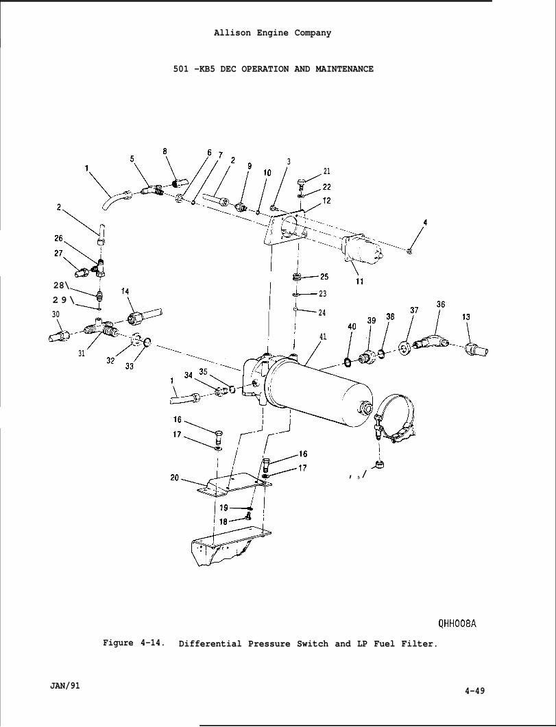
Allison Engine Company
501 -KB5 DEC OPERATION AND MAINTENANCE
1
\
28\2 9 \30
<
/31
310 21
[/
i?’/::
‘&
:. >.,-~ Ii// -. ,! -<--
II ‘ ‘=-...
I fjii+--25 ‘
y=
23
24
41
11
J+--+!!?!!” , 5/
QHHO08A
Figure 4-14. Differential Pressure Switch and LP Fuel Filter.
JAN/91 4-49
.
Allison Engine Company
501-KB5 DEC OPERATION AND MAINTENANCE
D. Install filter outlet pressure hose (2) to union (9). Torque hose’scoupling nut to 80-120 lb in. (9.0-13.5 Nom).
NOTE
If the optional filter inlet gage is not installed, a cap is used at thefilter inlet gage pressure hose connection.
E. Install filter inlet pressure hose (1) and filter inlet gage pressurehose (8) to tee (5). Torque hoses’ coupling nuts to 80-120 lb in.(9.0 -13.5 Nom). Tighten nut (6).
F. Bleed system per preceding Paragraph 4-58, Step F.
4-61. LP Fuel Filter Removal.
A.
B.
c.
If
Provide a container to catch fuel drainage.
Remove different pressure switch (11, Figure 4-14) per precedingParagraph 4-59.
Remove filter inlet pressure hose (1) from reducer (34).
NOTE
the optional filter outlet gage is not installed, a cap is used atthe filter outlet gage pressure hose connection.
D.
E.
Ifis
F.
G.
H.
4-50
Remove filter outlet pressure hose (2) and filter outlet gagepressure hose (27) from swivel nut tee (26).
Remove fuel inlet hose (13) from elbow (36).
NOTE
the optional fuel heating pressure regulator is not installed, a capused at the fuel heating pressure regulator supply hose connection.
Remove fuel outlet hose (14) and fuel heating pressure regulatorsupply hose (30) from connector tee (31).
Remove bracket clamp nut (15).
Remove bolts (16), washers (17), LP fuel filter (41), and brackets(12 and 20).
JAN/91
Allison Engine Company
501 -KB5 DEC OPERATION AND MAINTENANCE
NOTE
Remove the following only if replacement of the LF fuel filter isrequired. Record position of the tee and elbow fittings forinstallation. -
I. Remove bolts (18), washers (19),
J. Remove bolts (21), washers (22),bracket (12) with grommet (25).unless they are damaged.
and mounting bracket (20).
spacers (23), sleeves (24), andDo not remove grommet from bracket
K. Remove swivel nut tee (26) from union
L. Remove union (28) and O-ring (29) fromO-ring.
28) .
connector tee (31). Discard
M. Remove connector tee (31), nut (32), and O-ring (33). DiscardO-ring.
N. Remove reducer (34) and O-ring (35). Discard O-ring.
O. Remove elbow (36), nut (37), and O-ring (38). Discard O-ring.
P. Remove reducer (39) and O-ring (40). Discard O-ring.
4-62. LP Fuel Filter Installation.
NOTE
If LP fuel filter was replaced, do the following Steps A. to F.
A. Install O-ring (40, Figure 4-14) on reducer (39) and install reducedin LP fuel filter (41). Torque reducer to 600-840 lb in. (67.8-94.9N-m).
B. Install nut (37) and O-ring (38) on elbow (36). Install elbow inreducer (39) to position recorded on removal. Do not tighten nut(37) now.
C. Install O-ring (35) on reducer (34). Install,reducer in LP fuelfilter (41). Torque reducer to 55-80 lb in. (6.3-9.0 Nom).
D. Install nut (32) and O-ring (33) on connector tee (31). Installconnector tee in LF fuel filter (41) to position recorded onremoval. Do not tighten nut (32) now.
E. Install O-ring (29) on union (28). Install union on connector tee(31). Torque union to 55-80 lb in. (6.2-9.0 N-m).
JAN/91 4-51
F. Instal40-65
G. Instalhose’s
Allison Engine Company
501-KB5 DEC OPERATION AND MAINTENANCE
swivel nut tee (26) on union (28). Torque swivel nut tee tob in. (4.6-7.3 N“m).
filter inlet pressure hose (1) to reducer (34). Torquecoupling nut to 80-120 lb in. (9.0-13.5 Nom).
NOTE
If the optional filter outlet gage is not installed, a cap is used atthe filter outlet gage pressure hose connection.
H.
I.
J.
K.
L.
M.
If
Install filter outlet pressure hose (2) and filter outlet gagepressure hose (27) to swivel nut tee (26). Retain swivel nut teefrom turning and torque hoses’ coupling nut to 80-120 lb in.(9.0 -13.5 Nom).
If removed, install grommets (25) in bracket (12).
Install bracket (12) to LP fuel filter (41) and secure with sleeves(24),60-65
Insta”boltsN-m).
Insta”boltsNom).
spacers (23),’washers (22) and bolts’. Torque bolts tolb in. (6.8-7.3 N“m). Lockwire bolts.
1 mounting bracket (20) to LP fuel filter (41) and secure with(18) and washers (19). Torque bolts to 60-65 lb in. (6.8-7.3Lockwire bolts.
1 mounting bracket (20) and LP fuel filter (41) and secure with(16), and washers (17). Torque bolts to 74-89 lb in. (8.4-10.0
Install clamp on LP fuel filter and secure with bracket clamp(15) . Torque bracket clamp nut to 74-89 lb in. (8.4 -10.0 N-m,
NOTE
nut.
the o~tional fuel heatina is not installed. a can is used at the fuelheating pressure regulator supply hose connection.
N. Install fuel outlet hose (14) and fuel heating pressure regulatorsupply hose (30) to connector tee (31). Torque hoses’ coupling nutto 475-575 lb in. (53.7-64.9 Nom). Tighten nut (32).
O. Install fuel inlet hose (13) to elbow (36). Torque fuel inlet hosecoupling nut to 475-575 lb in. (53.7-64.9 Nom). Tighten nut (38).
P. Install different pressure switch (11) per preceding Paragraph 4-60.
Q. Bleed system of air per preceding Paragraph 4-58, Step F.
4-52 JAN/91
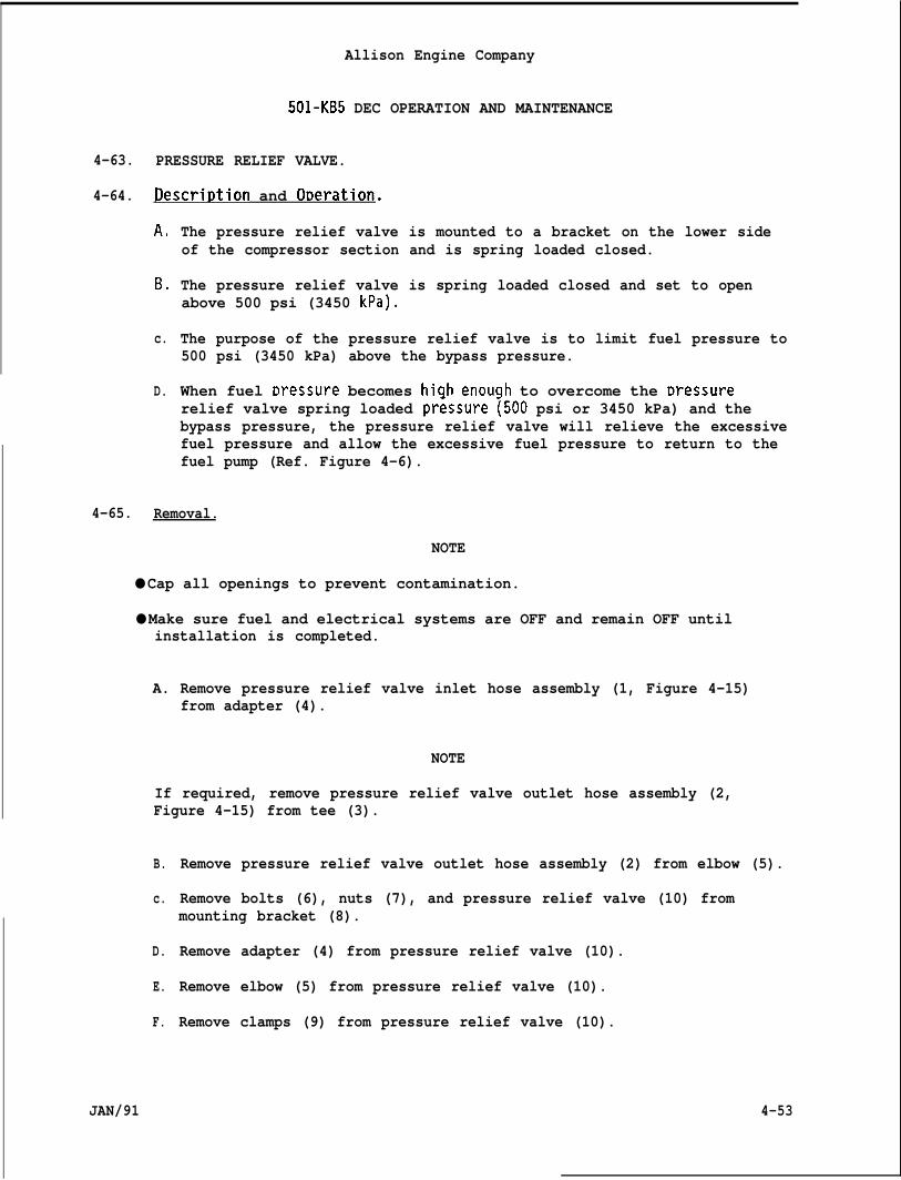
Allison Engine Company
501-KB5 DEC OPERATION AND MAINTENANCE
4-63. PRESSURE RELIEF VALVE.
4-64. Descrit)tion and ODeration.
A.
B,
c.
D.
The pressure relief valve is mounted to a bracket on the lower sideof the compressor section and is spring loaded closed.
The pressure relief valve is spring loaded closed and set to openabove 500 psi (3450 kPa).
The purpose of the pressure relief valve is to limit fuel pressure to500 psi (3450 kPa) above the bypass pressure.
When fuel r)ressure becomes hiqh enouclh to overcome the Dressurerelief valve spring loaded pr=ssure ~500 psi or 3450 kPa) and thebypass pressure, the pressure relief valve will relieve the excessivefuel pressure and allow the excessive fuel pressure to return to thefuel pump (Ref. Figure 4-6).
4-65. Removal.
NOTE
● Cap all openings to prevent contamination.
● Make sure fuel and electrical systems are OFF and remain OFF untilinstallation is completed.
A. Remove pressure relief valve inlet hose assembly (1, Figure 4-15)from adapter (4).
NOTE
If required, remove pressure relief valve outlet hose assembly (2,Figure 4-15) from tee (3).
B.
c.
D.
E.
F.
JAN/91
Remove pressure relief valve outlet hose assembly (2) from elbow (5).
Remove bolts (6), nuts (7), and pressure relief valve (10) frommounting bracket (8).
Remove adapter (4) from pressure relief valve (10).
Remove elbow (5) from pressure relief valve (10).
Remove clamps (9) from pressure relief valve (10).
4-53
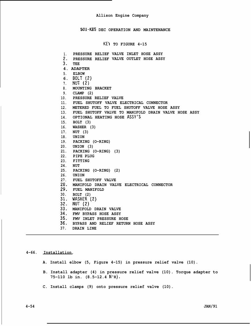
Allison Engine Company
501-KB5 DEC OPERATION AND MAINTENANCE
KE\
1. PRESSURE RELIEFPRESSURE RELIEF
:: TEE4. ADAPTER5. ELBOW6. EM#(;)7.
TO FIGURE 4-15
VALVE INLET HOSE ASSYVALVE OUTLET HOSE ASSY
8.9.
10.11.12.13.14.15.16.17.18.19.20.21.22.23.24.25.26.27.
;::30.
:;:
:;:
:::37.
MOUNTING BRACKETCLAMP (2)PRESSURE RELIEF VALVEFUEL SHUTOFF VALVE ELECTRICAL CONNECTORMETERED FUEL TO FUEL SHUTOFF VALVE HOSE ASSYFUEL SHUTOFF VALVE TO MANIFOLD DRAIN VALVE HOSE ASSYOPTIONAL HEATING HOSE ASSY’SBOLT (3)WASHER (3)NUT (3)UNIONPACKING (O-RING)UNION (3)PACKING (O-RING) (3)PIPE PLUGFITTINGNUTPACKING (O-RING) (2)UNIONFUEL SHUTOFF VALVEMANIFOLD DRAIN VALVE ELECTRICAL CONNECTORFUEL MANIFOLDBOLT (2)W:H~J)(2)
MANIFOLD DRAIN VALVEFMV BYPASS HOSE ASSYFMV INLET PRESSURE HOSEBYPASS AND RELIEF RETURN HOSE ASSYDRAIN LINE
4-66. Installation.
A. Install elbow (5, Figure 4-15) in pressure relief valve (10).
B. Install adapter (4) in pressure relief valve (10). Torque adapter to75-110 lb in. (8.5-12.4 N+m).
C. Install clamps (9) onto pressure relief valve (10).
4-54 JAN/91
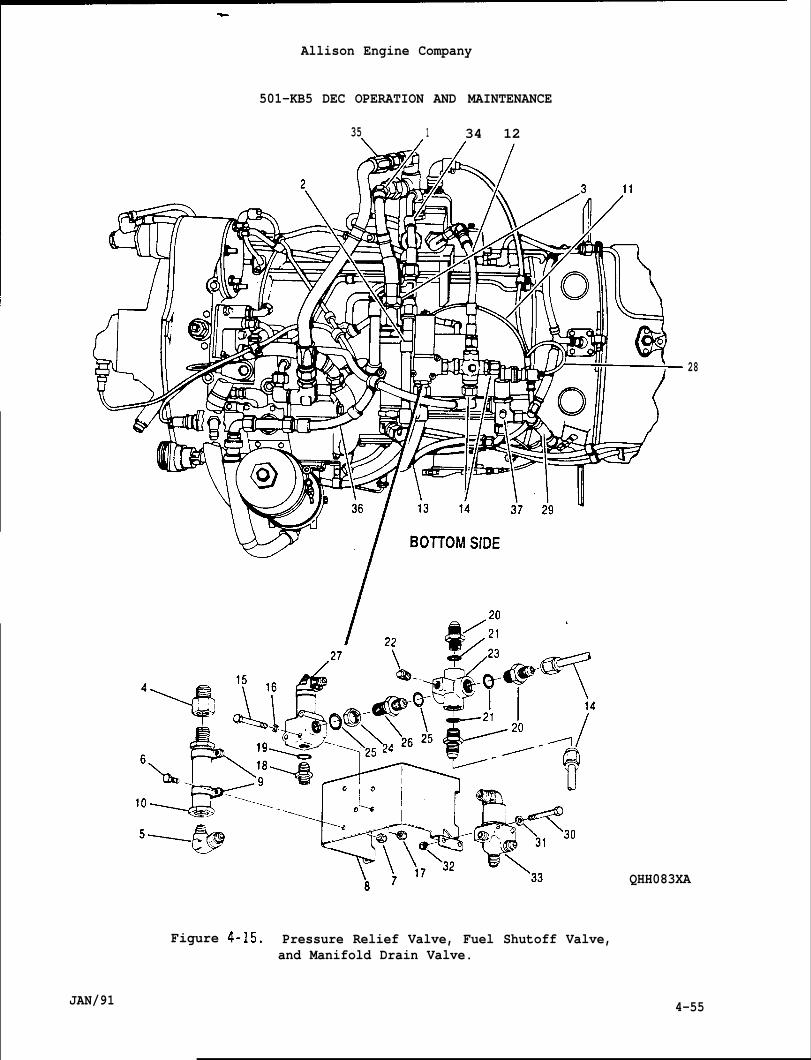
.
Allison Engine Company
501-KB5 DEC OPERATION AND MAINTENANCE
35 1 34 12
Figure 4-15. Pressure Relief Valve, Fuel Shutoff Valve,and Manifold Drain Valve.
28
QHH083XA
JAN/91 4-55
Allison Engine Company
501-KB5 DEC OPERATION AND MAINltNANLE
D. Install pressure relief valve (10) to mounting bracket (8), securewith bolts (6) and nuts (7). Torque nuts to 37-42 lb in. (4.2-4.7N“m).
E. Install pressure relief valve outlet hose assembly (2) to elbow (5).Torque hose coupling nut to 475-575 lb in. (53.7-64.9 N-m).
F. Install pressure relief valve inlet hose assembly (1) to adapter(4). Torque hose coupling nut to 475-575 lb in. (53.7- 64.9 N”m).
G. Pressurize fuel system and inspect pressure relief valve and fittingconnections for leaks.
4-67. FUEL METERING VALVE (FMV).
4-68. Descri~tion and O~eration.
A. The fuel metering valve (FMV) is mounted on engine compressor caseand meters the fuel to the engine in accordance with voltage commandsfrom the electronic control system, also includes a differentialpressure regulating valve to maintain an constant pressure across theFMV by bypass fuel back to the fuel pump inlet.
B. The FMV is a flapper type valve which is positioned by a proportionalsolenoid assembly with integral servo system. The FMV is positionedas a function of the input command voltage (O to 5 volts) from thecontrol system. A feedback output voltage from a linear variabledifferential transformer (LVDT) proportional to FMV position (meter-ing area) develops a O to -5 volts position analog. The positionsignal is compared to the O to 5 volts input command signal. If theposition feedback does not compare to the input command signal fromthe control system, the current in the proportional solenoid isvaried until the position signal equals the command input.
C. The FMV inlet pressure in normal operation can range from 60 to 600psig (414 to 4140 kPag) and sometimes as high as 700 psig (4830 kPag)at shutdown. The bypass pressure normally ranges between O to 150psig (O to 1035 kPag). The pressure drop from inlet to discharge tothe engine must not exceed 70 psi (483 kPa) at an engine fuel flow of3250 pph (1474 kg ph) with a supply flow of6000 pph (2722 kg ph).The FMV can regulate the pressure drop to 45-55 psi (311-379 kPa) atan fuel flow of 200 pph (91 kg ph) and over and inlet flow range of1,000 to 10,000 pph (454-4536 kg ph).
4-69. Removal.
CAUTION
NO FIELD ADJUSTMENTS TO THE FMV IS ALLOWED. DAMAGE MAY OCCUR FROM AMALFUNCTION, AND/ORMISADJUSTED FMV.
4-56 JAN/91
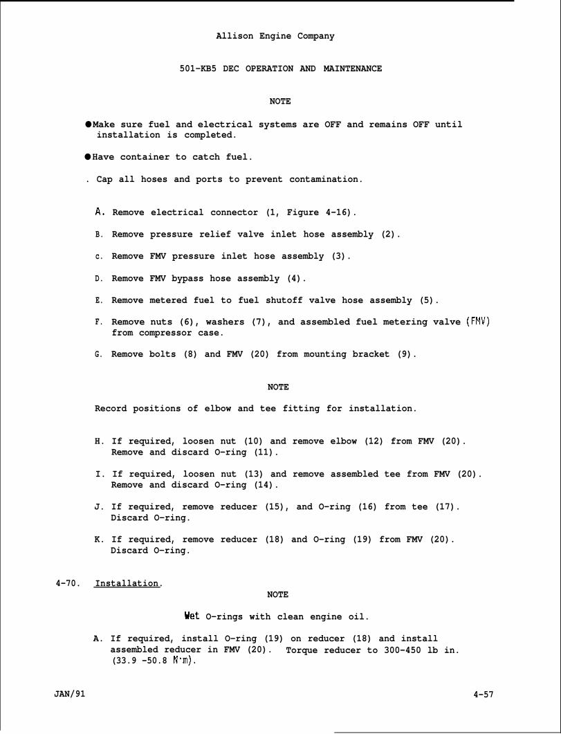
Allison Engine Company
501-KB5 DEC OPERATION AND MAINTENANCE
NOTE
● Make sure fuel and electrical systems are OFF and remains OFF untilinstallation is completed.
● Have container to catch fuel.
. Cap all hoses and ports to prevent contamination.
A.
B.
c.
D.
E.
F.
G.
Remove electrical connector (1, Figure 4-16).
Remove pressure relief valve inlet hose assembly (2).
Remove FMV pressure inlet hose assembly (3).
Remove FMV bypass hose assembly (4).
Remove metered fuel to fuel shutoff valve hose assembly (5).
Remove nuts (6), washers (7), and assembled fuel metering valve (FMV)from compressor case.
Remove bolts (8) and FMV (20) from mounting bracket (9).
NOTE
Record positions of elbow and tee fitting for installation.
H. If required, loosen nut (10) and remove elbow (12) from FMV (20).Remove and discard O-ring (11).
I. If required, loosen nut (13) and remove assembled tee from FMV (20).Remove and discard O-ring (14).
J. If required, remove reducer (15), and O-ring (16) from tee (17).Discard O-ring.
K. If required, remove reducer (18) and O-ring (19) from FMV (20).Discard O-ring.
4-70. Installation.NOTE
Uet O-rings with clean engine oil.
A. If required, install O-ring (19) on reducer (18) and installassembled reducer in FMV (20). Torque reducer to 300-450 lb in.(33.9 -50.8 Nom).
JAN/91 4-57
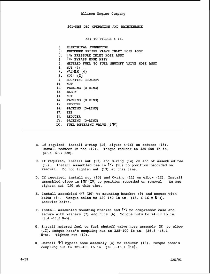
Allison Engine Company
501-KB5 DEC OPERATION AND MAINTENANCE
KEY TO FIGURE 4-16.
1.
::4.5.6.
i9.
10.11.12.13.14.15.16.17.18.
;::
ELECTRICAL CONNECTORPRESSURE RELIEF VALVE INLET HOSE ASSYFMV PRESSURE INLET HOSE ASSYFMV BYPASS HOSE ASSYMETERED FUEL TO FUEL SHUTOFF VALVE HOSE ASSYNUT (4)[~M7E~3j4)
MOUNTING BRACKETNUTPACKING (O-RING)ELBOWNUTPACKING (O-RING)REDUCERPACKING (O-RING)TEEREDUCERPACKING (O-RING)FUEL METERING VALVE (FMV)
B. If required, install O-ring (16, Figure 4-16) on reducer (15).Install reducer in tee (17). Torque reducer to 420-600 lb in.(47.5 -67.7 Nom).
C. If required, install nut (13) and O-ring (14) on end of assembled tee(17). Install assembled tee in FMV (20) to position recorded onremoval. Do not tighten nut (13) at this time.
D. If required, install nut (10) and O-ring (11) on elbow (12). Installassembled elbow in FMV (20) to position recorded on removal. Do nottighten nut (10) at this time.
E. Install assembled FMV (20) to mounting bracket (9) and secure withbolts (8). Torque bolts to 120-150 lb in. (13. 6-16.9 Nom).Lockwire bolts.
F. Install assembled mounting bracket and FMV to compressor case andsecure with washers (7) and nuts (6). Torque nuts to 74-89 lb in.(8.4 -10.0 Nom).
G. Install metered fuel to fuel shutoff valve hose assembly (5) to elbow(12). Torque hose’s coupling nut to 325-400 lb in. (36.8 -45.1N-m). Tighten nut (10).
H. Install FMV bypass hose assembly (4) to reducer (18). Torque hose’scoupling nut to 325-400 lb in. (36.8-45.1 N“m).
4-58 JAN/91
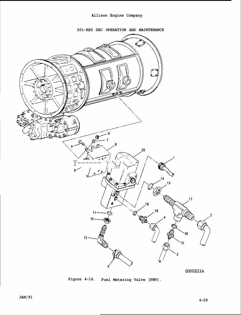
501-KB5 DEC OPERATION AND MAINTENANCE
Y—----- )! - -y# k’+
\
Q&/ /7’\*
Allison Engine Company
4-59JAN/91
w
Figure 4-16. Fuel Metering Valve (FMV).
Allison Engine Company
501-KB5 DEC OPERATION AND MAINTENANCE
I. Install FMV pressure inlet hose assembly (3) and pressure reliefvalve inlet hose (2) to tee (17). Tighten nut (13). Torque bothhose’s coupling nuts to 325-400 lb in. (36.8-45.1 N“m).
J. Using 5/16 (0.3125) inch Allen wrench loosen bleed plug (24) andmotor engine to bleed a
NO FIELD ADJUSTMENT TO THE
r from fuel system. Tighten bleed plug.
CAUTION
FUEL METERING VALVE ARE ALLOWED.
NOTE
Flake sure electrical power is OFF.
K. Install electrical connector (1) to FMV (20). Tighten and lockwireelectrical connector.
L. Perform an operation and leakage test.
4-71. FUEL SHUTOFF VALVE.
4-72. Descrit)tion and ODeration.
A.
B.
c.
D.
The fuel shutoff valve is on the bottom of the compressor section tomounting bracket.
In fuel flow path, the fuel shutoff valve is located between the fuelmetering valve and manifold drain valve and is a normally closedelectrical solenoid operated valve (Ref. Figure 4-6).
The fuel shutoff valve electrical power is controlled by the controlsystem. During the starting cycle at 2200 engine rpm, electricalpower from control system is sent to open the fuel shutoff valve.The fuel shutoff valve will close whenever the electrical power isremoved by the shutdown circuits of the control system.
The purpose of the fuel shutoff valve is to control the metered fuelto the fuel manifold and fuel nozzles thru the manifold drain valve.The fuel shutoff valve provides the only means of shutting down theengine operation by stopping the metered fuel flow.
4-73. Inspection.
A. Remove fuel shutoff valve to manifold drain valve hose assembly (13,Figure 4-15) from union (18).
4-60 JAN/91
4-74.
●
●
●
●
JAN/91
Allison Engine Company
501-KB5 DEC OPERATION AND MAINTENANCE
B. Place a container under union (18) and motor the engine for oneminute with fuel and ignition O.FF. If more than 2 cc comes fromunion, the fuel shutoff valve must be replaced.
C. Install fuel shutoff valve to manifold drain valve hose assembly (13)to union (18). Torque hose coupling nut to 325-400 lb in. (36.8-45.1N.m).
Removal.
NOTE
Cap all openings to prevent contamination.
Make sure fuel and electrical systems are OFF and remain OFF untilinstallation is completed.
A. Remove the fuel shutoff valve electrical connector (11, Figure 4-15).
B. Remove meter fuel to fuel shutoff valve hose assembly (12) and fuelshutoff valve to manifold drain valve hose assembly (13).
NOTE
If the optional fuel heating is not installed,capped.
If
c.
D.
E.
F.
G.
H.
required, record position of caps for insta”
outlets will be
lation.
Remove optional heating hose assemblies (14) from unions (20).
Remove bolts (15), washers (16), nuts (17), and fuel shutoff valve(27) from the mounting bracket (8).
Remove union (18) and O-ring (19) from fuel shutoff valve (27).Discard O-ring.
Remove unions (20) and O-rings (21) from fitting (23). DiscardO-rings.
Remove pipe plug (22) from fitting (23).
NOTE
Record position of fitting for installation.
Loosen nut (24) and remove fitting (23) and union (26).
4-61
Allison Engine Company
501-KB5 DEC OPERATION AND MAINTENANCE
I. Remove union (26) from fitting (23).
J. Remove nut (24) and O-rings (25) from union (26). Discard O-rings.
NOTE
No repairs are allowed to the fuel shutoff valve.
4-75. Installation.
NOTE
Wet O-ring with clean engine oil.
A. Install O-rings (25, Figure 4-15) and nut (24) on union (26).
B. Install union (26) in fitting (23).
C. Install pipe plug (22) in fitting (23). Tighten pipe plug.
D. Install O-rings (21) on Unions (20).
E. Install unions (20) in fitting (23). Torque all unions to 200-300 lbin. (22.6 -33.8 Nom).
NOTE
If optional fuel heating system is not installed, install caps on therecorded two unions.
F. If required, install caps on two unions (20) recorded on removal,
G. Install fitting (23) and union (26) on fuel shutoff valve to positionmark on removal. Tighten nut (24).
H. Install O-ring (19) on union (18) and install union on fuel shutoffvalve (27). Torque union to 200-300 lbs in. (22.6-33.8 N+m).
I. Install assembled fuel shutoff valve (27) to mounting bracket (8) andsecure with bolts (15), washers (16), and nuts (17). Torque nuts to74-89 lb in. (8.4-10.0 Nom).
J. Install meter fuel to fuel shutoff valve hose (12) to union (20).Torque hose’s coupling nut to 325-400 lb in. (36.8-45.1 Nom).
K. If required, install optional heating hose assemblies (14) to unions(20). Torque hoses’ coupling nuts to 325-400 lb in. (36.8-45.1N“m).
L. Install fuel shutoff valve electrical connector (11) to fuel shutoffvalve (27). Lockwire connector.
4-62 JAN/91
4-76.
4-77.
4-78.
4-79.
JAN/91
Allison Engine Company
501 -KB5 DEC OPERATION AND MAINTENANCE
M. With empty container position at union (18), motor for one minutewith fuel and ignition OFF. If more than 2CC of fuel comes fromunion, the fuel shutoff valve must be replaced.
N. Install fuel shutoff valve to manifold drain valve hose assembly (13)to union (18). Torque hose coupling nut to 325-400 lb in. (36.8-45.1Nom).
O. Perform an operation and leakage test.
MANIFOLD DRAIN VALVE.
Description and Operation.
A.
B.
c.
The manifold drain valve is located on bottom of the fuel manifoldmounted to a mounting bracket. It is a spring loaded solenoidoperated valve designed to drain the fuel manifold when engine isshut down (not operating) and minimizing the amount of fuel drippinginto the combustion liners at extremely low pressures, 8 to 10 psig(55.2 to 69 kPag).
During the engine starting cycle, the manifold drain valve is closedby the control system energizing the solenoid at 2200 engine rpm andis held closed by the subsequent buildup of fuel pressure, above thespring operating pressure, within the fuel manifold. The solenoid isde-energized by the control system at 8400 engine rpm. When fuelmanifold pressure drops below spring-loaded operating pressure, thespring will open the manifold drain valve, and allow drainage of thefuel from the fuel manifold.
The operating pressure is 8 to 10 psig (55.2 to 69 kPag) for thespring-loaded portion of the manifold-drain valve. -
Removal.
A.
B.
c.
Remove manifold drain valve electrical connector (28, Figure 4-15).
Remove fuel shutoff valve to manifold drain valve hose assembly (13),drain line (37), and fuel manifold (29).
Remove bolts (30). washers (311. nuts (32). and manifold drain valve(33) from mounting bracket ~8)~ ‘ ‘ ‘ ‘
Installation.
A. Install manifold(8) and secure wnuts to 74-89 lb
drain valve (33, Figure 4-15) to mounting bracketth bolts (30), washers (31), and nuts (32). Torquein. (8.4 -10.0 N-m).
4-63
Allison Engine Company
501-KB5 DEC OPERATION AND MAINTENANCE
B. Install fuel shutoff valve to manifold drain valve hose assembly (13)to the IN port of manifold drain valve (33). Torque hose’s couplingnut to 325-400 lb in. (36.8-45.1 Nom).
C. Install fuel manifold (29) to the OUT port of the manifold drainvalve (33). Torque fuel manifold’s coupling nut to 325-400 lb in.(36.8 -45.1 Nom).
NOTE
If the angle of the electrical connector on the replacement manifolddrain valve will not permit connection of manifold drain valveelectrical connector, loosen nut on top of the solenoid housing andreposition the housing. Torque nut to25-351b in. (2.8-4.0 N”m).
D. Install manifold drain valve electrical connector (28) and lockwire.
E. Test the manifold drain valve for satisfactory operation perParagraph 4-80.
F. Install drain line (37) to the DRAIN port of the manifold drain valve(33). Torque drain line’s coupling nut to 80-120 lb in. (9.0-13.5Nom).
4-80. Inspection and Test.
A.
B.
c.
D.
E.
F.
G,
4-64
Position a container under DRAIN port and if required, remove thedrain line (37, Figure 4-15).
Disconnect electrical input lead assemblies to the ignition exciter(Ref. Ignition System, Section 9).
Set up engine controls for a START.
Engage START button and allow engine to accelerate above 2200 rpm,there should be no fuel drainage at the manifold drain valve DRAINport while the starter is energized, push the STOP button.
Observe the fuel drainage from the manifold drain valve’s DRAINport. Fuel drainage will occur when the starter is released and thefuel manifold pressure drops below spring loaded operating pressure,8-10 psig. (55.2-69 kPag).
After engine coast, install electrical input lead assemblies to theignition exciter (Ref. Ignition System Section 9).
During the first engine run after a manifold drain valve replacement,test for leakage at the DRAIN port during engine operation. Replacemanifold drain valve if leakage exceeds 40 drops per minute.
JAN/91
.
Allison Engine Company
501-KB5 DEC OPERATION AND MAINTENANCE
4-81. BURNER DRAIN VALVES.
4-82. Descri L)tion and Or)eration.
A. Two burner drain valves are located on the bottom of the outercombustion case. One is near the forward end, the other is nearthe rear end.
B. Each burner drain valve is a spring loaded, flat plate typevalve. The burner drain valves remains open until the combustioncase internal pressure increases to 5-10 psig (34.5-69.0 kPag). Itopens and remains open by spring action when the pressure falls to1-3 psig (6.9-20.7 kPag).
C. The burner drain valves prevent accumulation of fuel in thecombustion section by draining it after an unsuccessful start orafter stopping the engine.
4-83. Removal.
I CAUTION
AN ATTEMPT TO REMOVE THE BOLTS WITHOUT USING A PENETRATING OIL MAYCAUSE THE THREADS TO STRIP DURING REMOVAL.
I A. Remove the drain hose.
B. Apply penetrating oil, VV-P-216, to the bolts (6, Figure 4-17).Allow sufficient time for oil to penetrate the threads.
C. Remove bolts (6) and the burner drain valve (8). Remove and discardthe gasket (7).
4-84. Maintenance and Ins~ection.
A. Unscrew the adapter (5, Figure 4-17) from the body (l). Remove valve(2), spring (3), and gasket (4). Discard gasket.
B. Inspect the adapter (5) and body (1) for thread damage andcorrosion. If the threads are damaged, the burner drain valve mustbe replaced.
WARNING
CLEANING SOLVENT FED. SPEC. P-D-680-2 IS TOXIC. PROVIDE ADEQUATEVENTILATION.
C. Clean all the parts with Fed. Spec P-D-680-2 cleaning solvent(mineral spirits), using a wire brush. If required, polish body (1)with crocus cloth.
JAN/91 4-65
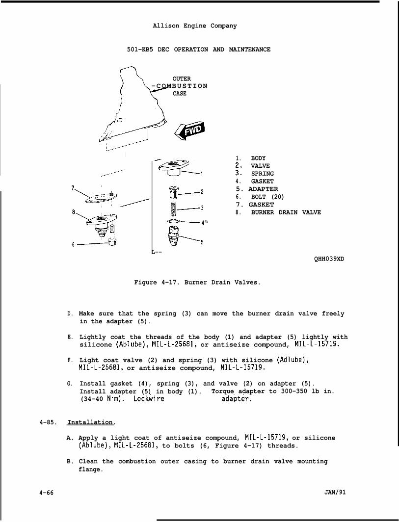
Allison Engine Company
501-KB5 DEC OPERATION AND MAINTENANCE
n OUTER
D-COMBUSTION
CASE
‘i” J’@@. .
//“
6
D.
E.
F.
G.
-----+3
1. BODYVALVE
:: SPRING4. GASKET
*J6~z 5. ADAPTER
6. BOLT (20)&$~3 7. GASKET= 8. BURNER DRAIN VALVE&—4“
f?’ 5L--
Figure 4-17. Burner Drain Valves.
QHH039XD
Make sure that the spring (3) can move the burner drain valve freelyin the adapter (5).
Lightly coat the threads of the body (1) and adapter (5) lightly withsilicone (Ablube), MIL-L-25681, or antiseize compound, MIL-L-15719.
Light coat valve (2) and spring (3) with silicone (Adlube),MIL-L-25681, or antiseize compound, MIL-L-15719.
Install gasket (4), spring (3), and valve (2) on adapter (5).Install adapter (5) in body (1). Torque adapter to 300-350 lb in.(34-40 N-m)’. Lockwire adapter;
4-85. Installation.
A. Apply a light coat of antiseize compound, MIL-L-15719, or silicone(Ablube), MIL-L-25681, to bolts (6, Figure 4-17) threads.
B. Clean the combustion outer casing to burner drain valve mountingflange.
4-66 JAN/91
4-86.
4-87.
4-88.
4-89.
JAN/91
Allison Engine Company
501-KB5 DEC OPERATION AND MAINTENANCE
C. Install a gasket (7) and burner drain valve (8) to the bottom of theouter combustion casing mounting flange with bolts (6). Torque boltsto 70-85 lb in. (7.9-9.6 N“m). Lockwire bolts.
D. Connect the drain hose to the burner drain valve. Torque hosecoupling nut to 200-250 lb in. (22.6-28.3 Nom).
Troubleshootinq.
WARN ING
BURNING DRAIN LINES MAY BE HOT IF BURNER DRAIN VALVES ARE STUCK OPEN.INJURY MAY OCCUR.
A. While the engine is running, feel the lower end of the burner drainline(s).
B. If the line(s) are hot, a burner drain valve(s) is leaking and mustbe cleaned, repaired, or replaced.
FUEL LINES AND HOSES.
NOTE
All flexible fuel lines furnished with the engine have an inner core ofteflon, protected by one or more layers of protective material and abraided metal sheath. These hoses are very durable and not prone todeterioration, however they are susceptible to damage from sharp bends,kinks, twists and crushing. Evidence of such damage to the teflon coreis difficult to detect. If damage is suspected, the hose must bereplaced or pressure tested.
A. All fuel lines and hoses should be inspected regularly for:
1. Leaks2. Chaffing3. Wear4. Damage coupling nuts (connectors)5. Kinks6. Twisting7. Swelling8. Crushing
SINGLE ENTRY FUEL NOZZLE (FUEL NOZZLE).
Descri~tion and Operation.
A. Each fuel nozzle consists of a dual atomizing system which incor-porates a pilot (primary) injector for starting and an airblast
4-67
Allison Engine Company
501-KB5 DEC OPERATION AND MAINTENANCE
4-90.
●
●
4-68
B.
c.
(main) injector for the remaining fuel. The pilot injector atomizesfuel by means of fuel pressure in the pilot spray tip orifice whichforces the fuel through small tangential holes in the metering setassembly. The fuel from the sixteen main jets in the main injectrris atomized by compressor air which passes through the air shroudswirler and blasts the fuel from the main jets to achieve a good fueland air mixing (Ref. Figure 4-18).
The fuel nozzle employs a single entry of fuel to service both, thepilot and main, atomizing systems and spring loaded piston and sleeveassembly which meters fuel flow to the main injector. On starting,fuel flows through the filter screen, along the flats of the valvebody, through the metering set’s tangential holes, and finally exitsthrough the spray tip orifice. When the fuel pressure across thefuel nozzle reaches 150 psi (1035 kPa), the spring loaded piston andsleeve assembly opens and fuel flows through inside of valve body,through the axial holes in the spacer, forward end of the nozzle tipassembly, and finally exits through the sixteen main jets.
The six (6) single entry fuel nozzles are mounted on pads around thecompressor diffuser.
Removal.
NOTE
Cap all openings to prevent contamination.
Make sure fuel and electrical systems are OFF and remain OFF untilinstallation is completed.
A. Remove fuel manifold (1, Figure 4-19) from fuel nozzle (4).
CAUTION
PARTICULAR CARE MUST BE TAKEN DURING FUEL NOZZLE REMOVAL TO PREVENTDAMAGE TO THE FUEL NOZZLE. CARBON DEPOSITS ON THE FUEL NOZZLE TIP AREABRASIVE AND CAN DAMAGE THE ORIFICES IF HANDLING IS CARELESS.
B. Remove bolts (2), fuel nozzle (4), and gasket (3), using care toavoid damage to the fuel nozzle orifices. Discard gasket.
C. Install protective caps on the inlet and outlet fittings and placeremoved fuel nozzle in a protective storage case.
D. Repeat Steps 1., 2., and 3. to remaining fuel nozzles.
JAN/91
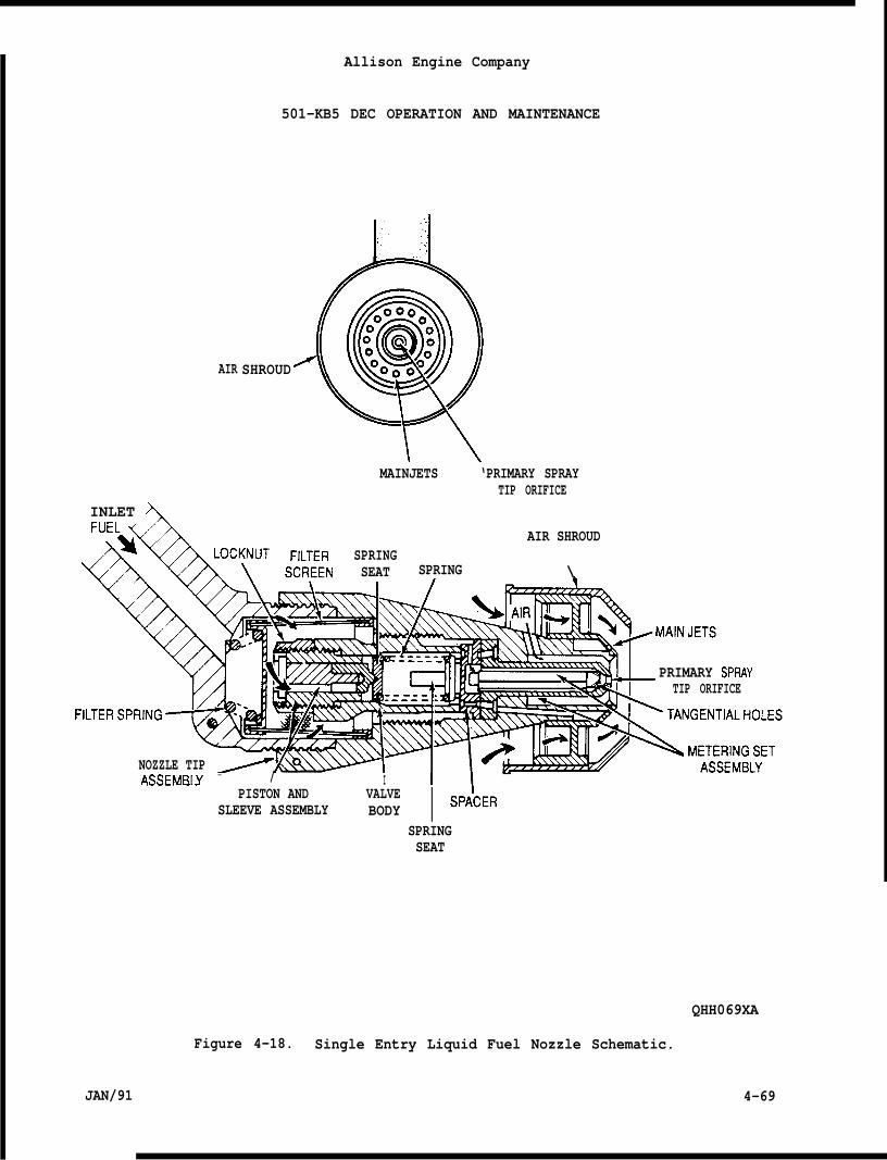
AIR
Allison Engine Company
501-KB5 DEC OPERATION AND MAINTENANCE
SHROUD
MAINJETS ‘PRIMARY SPRAYTIP ORIFICE
INLET AFUELA
%i LOC~UT FILTER SPRINGSCRFFN SEAT SPRING
AIR SHROUD
\
NOZZLE TIP
PRIMARY SPRAYTIP ORIFICE
ASSEMB[Y - / I 11------ . . .PISTON AND VALVE
SLEEVE ASSEMBLY BODY I SPA’CER
SPRINGSEAT
QHH069XA
Figure 4-18. Single Entry Liquid Fuel Nozzle Schematic.
JAN/91 4-69
Allison Engine Company
501-KB5 DEC OPERATION AND MAINTENANCE
—4-91.
4-92.
Insl)ection.
CAUTION
DO NOT DISASSEMBLE FUEL NOZZLES FOR INSPECTION. DISASSEMBLY IS NOTALLOWEDAT THIS MAINTENANCE LEVEL.
NOTE
Carbon deposits anywhere except aroundleakage, which is allowed.
the tip and shroud indicates
A. Visually inspect for excessive carbon accumulation on the fuelnozzles.
NOTE
Some carbon deposited around the pilot spray tip and the main jets isnormal . If there is no visible damage or hot spots in the associatedcombustion liners or turbine vanes as seen by borescope inspection, andif there are no startinq ~roblems or dark exhaust smoke, the carbon isnot interfering with th~ operation of the fuel nozzle and shoulddisturbed.
B. Replace or clean the fuel nozzles if excessive smoking occursthe exhaust or if carbon buildup appears to be restricting ordistorting the fuel flow.
not be
from
C. Warpage of the fuel nozzle air shroud or worn places through the wearcoating to the bare metal along the axial Portion of the air shroudthe fuel nozzle must be replac~d.
D. Any damage to the spray tip orifice or main jets which changes fue”flow characteristics or to the air shroud which changes air flowcharacteristics or to the internal screen which is suspected of beclogged the fuel nozzle must be replaced.
E. Replacement of individual liquid fuel nozzles is not allowed. Acomplete bench test is necessary to accurately determine which fuelnozzle(s) of the six are deficient. The fuel nozzles are changed insets of six (6).
Cleaning.
CAUTION
DO NOT DISASSEMBLE FUEL NOZZLES FOR CLEANING. DISASSEMBLY IS NOTALLOWED AT THIS MAINTENANCE LEVEL.
ng
4-70 JAN/91
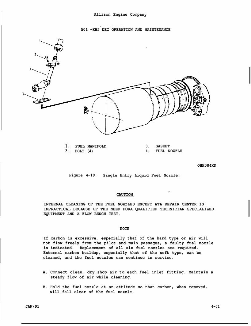
Allison Engine Company
.-. .— .. —— -501 -KB5 DEC OPERATION AND MAINTENANCE
3
FUEL MANIFOLD 3. GASKET;: BOLT (4) 4. FUEL NOZZLE
QHH084XD
Figure 4-19. Single Entry Liquid Fuel Nozzle.
.CAUTION
INTERNAL CLEANING OF THE FUEL NOZZLES EXCEPT ATA REPAIR CENTER ISIMPRACTICAL BECAUSE OF THE NEED FORA QUALIFIED TECHNICIAN SPECIALIZEDEQUIPMENT AND A FLOW BENCH TEST.
NOTE
If carbon is excessive, especially that of the hard type or air willnot flow freely from the pilot and main passages, a faulty fuel nozzleis indicated. Replacement of all six fuel nozzles are required.External carbon buildup, especially that of the soft type, can becleaned, and the fuel nozzles can continue in service.
A. Connect clean, dry shop air to each fuel inlet fitting. Maintain asteady flow of air while cleaning.
B. Hold the fuel nozzle at an attitude so that carbon, when removed,will fall clear of the fuel nozzle.
JAN/91 4-71
Allison Engine Company
501 -KB5 DEC OPERATION AND MAINTENANCE
C. Initially attempt to clean the tip with a cotton swab.
CAUTION
DO NOT WIPE OR CLEAN CARBON WITH SHOP TOWELS WHICH MAY ALLOW CARBON TOENTER THE FUEL NOZZLE ORIFICES. BLOCKAGE CAN OCCUR WHICH WILL ALTERFUEL NOZZLE OPERATION.
CAUTION
SCRAPERS MADE OF COPPER CAN BE USED TO CAREFULLY SCRAPE OFF THECARBON. SCRAPING MOTION SHOULD BEGIN NEARAN ORIFICE AND MOVE AWAY SOTHE CARBON FALLS FREE OF THE FUEL NOZZLE. MUCH CARE SHOULD BE TAKEN NOTTO PUSH CARBON INTO AN ORIFICE.
CAUTION
CARBON IS ABRASIVE. DO NOT CRUSH CARBON BETWEEN THE TOOL AND THESURFACE BEING RUBBED.
CAUTION
KEEP COPPER SCRAPER TOOLS SHARP AND SCRAPE JUST HARD ENOUGH TO BREAKTHE CARBON LOOSE.
D. If carbon can not be removed with a cotton swab, use copper scraperand carefully remove the external carbon.
4-93. Installation.
CAUTION
FUEL NOZZLES MUST BE REPLACED IN A MATCHED SET. DO NOT MIX FUELNOZZLES WITH DIFFERENT FLOW CHARACTERISTICS SUCH AS NEW AND USED FUELNOZZLES OR THOSE OF DIFFERENT PART NUMBER EVEN THOUGH THEY PHYSICALLYFIT. UNBALANCED FLOWS CAN CAUSE EXTENSIVE TURBINE DAMAGE.
A.
B.
c.
D.
E.
4-72
Apply a light coat of antiseize compound, MIL-L-15719, or Adlube,MIL-L-25681, to the threads of the bolts (2, Figure 4-19).
Carefully install gasket (3) and fuel nozzle (4) and secure withbolts (2). Torque bolts to 70-85 lb in. (7-9-9.6 N“m). Lockwirebolts.
Install fuel manifold (1) and torque coupling nut to 200-250 lb in.(22.6 -28.2 Nom).
Repeat Steps 1. thru 3. for remaining fuel nozzles.
Preform an operational and leakage check.
JAN/91
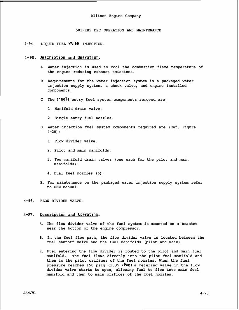
Allison Engine Company
501-KB5 DEC OPERATION AND MAINTENANCE
4-94. LIQUID FUEL WATER INJECTION.
4-95. Descri~tion and Oc)eration.
A. Water injection is used to cool the combustion flame temperature ofthe engine reducing exhaust emissions.
B. Requirements for the water injection system is a packaged waterinjection supply system, a check valve, and engine installedcomponents.
C. The single entry fuel system components removed are:
1. Manifold drain valve.
2. Single entry fuel nozzles.
D. Water injection fuel system components required are (Ref. Figure4-20):
1. Flow divider valve.
2. Pilot and main manifolds.
3. Two manifold drain valves (one each for the pilot and mainmanifolds).
4. Dual fuel nozzles (6).
E. For maintenance on the packaged water injection supply system referto OEM manual.
4-96. FLOW DIVIDER VALVE.
4-97. Description and ODeration.
A.
B.
c.
JAN/91
The flow divider valve of the fuel system is mounted on a bracketnear the bottom of the engine compressor.
In the fuel flow path, the flow divider valve is located between thefuel shutoff valve and the fuel manifolds (pilot and main).
Fuel entering the flow divider is routed to the pilot and main fuelmanifold. The fuel flows directly into the pilot fuel manifold andthen to the pilot orifices of the fuel nozzles. When the fuelpressure reaches 150 psig (1035 kPag) a metering valve in the flowdivider valve starts to open, allowing fuel to flow into main fuelmanifold and then to main orifices of the fuel nozzles.
4-73
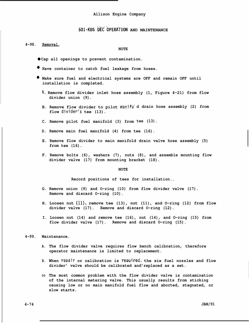
Allison Engine Company
501-ut5 DECOpERATION AND MAINTENANCE
4-98. Removal.NOTE
● Cap all openings to prevent contamination.
●
●
Have container to catch fuel leakage from hoses.
Make sure fuel and electrical systems are OFF and remain OFF untilinstallation is completed.
A. Remove flow divider inlet hose assembly (1, Figure 4-21) from flowdivider union (9).
B. Remove flow divider to pilot manifo”flow divider’s tee (13).
C. Remove pilot fuel manifold (3) from
d drain hose assembly (2) from
tee (13).
D. Remove main fuel manifold (4) from tee (16).
E. Remove flow divider to main manifold drain valve hose assembly (5)from tee (16).
F. Remove bolts (6), washers (7), nuts (8), and assemble mounting flowdivider valve (17) from mounting bracket (18).
NOTE
Record positions of tees for installation..
G. Remove union (9) and O-ring (10) from flow divider valve (17).Remove and discard O-ring (10).
H. Loosen nut (11), remove tee (13), nut (11), and O-ring (12) from flowdivider valve (17). Remove and discard O-ring (12).
I. Loosen nut (14) and remove tee (16), nut (14), and O-ring (15) fromflow divider valve (17). Remove and discard O-ring (15).
Maintenance.4-99.
co
4-74
A.
B.
The flow divider valve requires flow bench calibration, thereforeoperator maintenance is limited to replacement.
When reDair or calibration is reauired. the six fuel nozzles and flowdivider’ valve should be calibrated and’replaced as a set.
The most common problem with the flow divider valve is contaminationof the internal metering valve. This usually results from stickingcausing low or no main manifold fuel flow and aborted, stagnated, orslow starts.
JAN/91
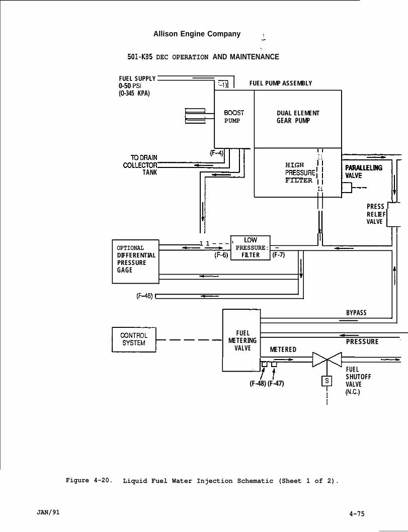
Allison Engine Company
. . .
501-KB5 DEC OPERATION AND MAINTENANCE
FUEL SUPPLY I
0-50 Psl(O-345 KPA)
} 1
t,I
TO DRAIN (
Cjjl FUEL PUMP ASSEMBLY
1300STPUMP
COLLECTOR~TANK
DUAL ELEMENTGEAR PUMP
IIIi
HIGH IIPRESSURE! ;FILTER II
Ii mlPARALLELINGVALVE
.-/
PRESS ~
II RELIEF
tVALVE
L
OPTIONAL 1 1 - - -‘ ‘owPRESSURE: — 11~DIFFERENTIAL ~ y+) FILTER (F-7)PRESSUREGAGE
~ It
(F+ I ~
BYPASS A
m“-”-
FUEL ~METERING PRESSURE -
VALVE METERED—
FUELSHUTOFF
(F-48) (F-47)v
a VALVE
I (N.C.)I
JAN/91
Figure 4-20. Liquid Fuel Water Injection Schematic (Sheet 1 of 2).
4-75
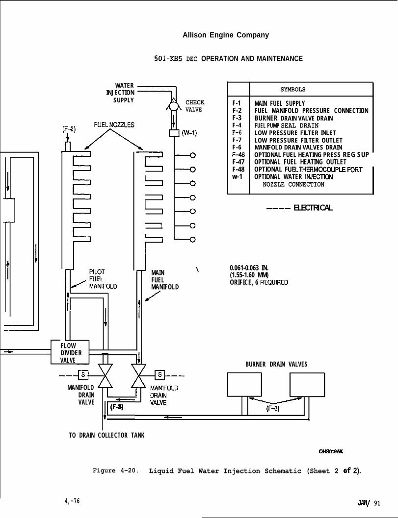
Allison Engine Company
—
501-KB5
WATERINJECTION
SUPPLY
T
DEC OPERATION AND MAINTENANCE
CHECKVALVE
SYMBOLS
F-1 MAIN FUEL SUPPLYF-2 FUEL MANIFOLD PRESSURE CONNECTIONF-3 BURNER DRAIN VALVE DRAINF-4 FUEL PUMP SEAL DRAINF-6 LOW PRESSURE FILTER INLETF-7 LOW PRESSURE FILTER OUTLETF-6 MANIFOLD DRAIN VALVES DRAINF+!6 OPTIONAL FUEL HEATING PRESS REG SUPF-47 OPTIONAL FUEL HEATING OUTLETF-48 OPTIONAL FUELTHERMOCOUPLEP ORTw-1 OPTIONAL WATER lNJECllON
NOZZLE CONNECTION
---- ELECTRICAL
I 1
I{[
I
1
1
MAIN \ 0.061-0.063 IN.
FUEL(1.55-1.60 MM)ORIFICE, 6 REOUIRED
MANIFOLD
t’/
j t
FLOW4 DIVIDER —
VALVE BURNER DRAIN VALVES——
MANIFOLDDRAINVALVE
l–
(F-8)y
e <
TO DRAIN COLLECTOR TANK
cx+smwuc
Figure 4-20. Liquid Fuel Water Injection Schematic (Sheet 2 of 2).
4,-76 JANf 91
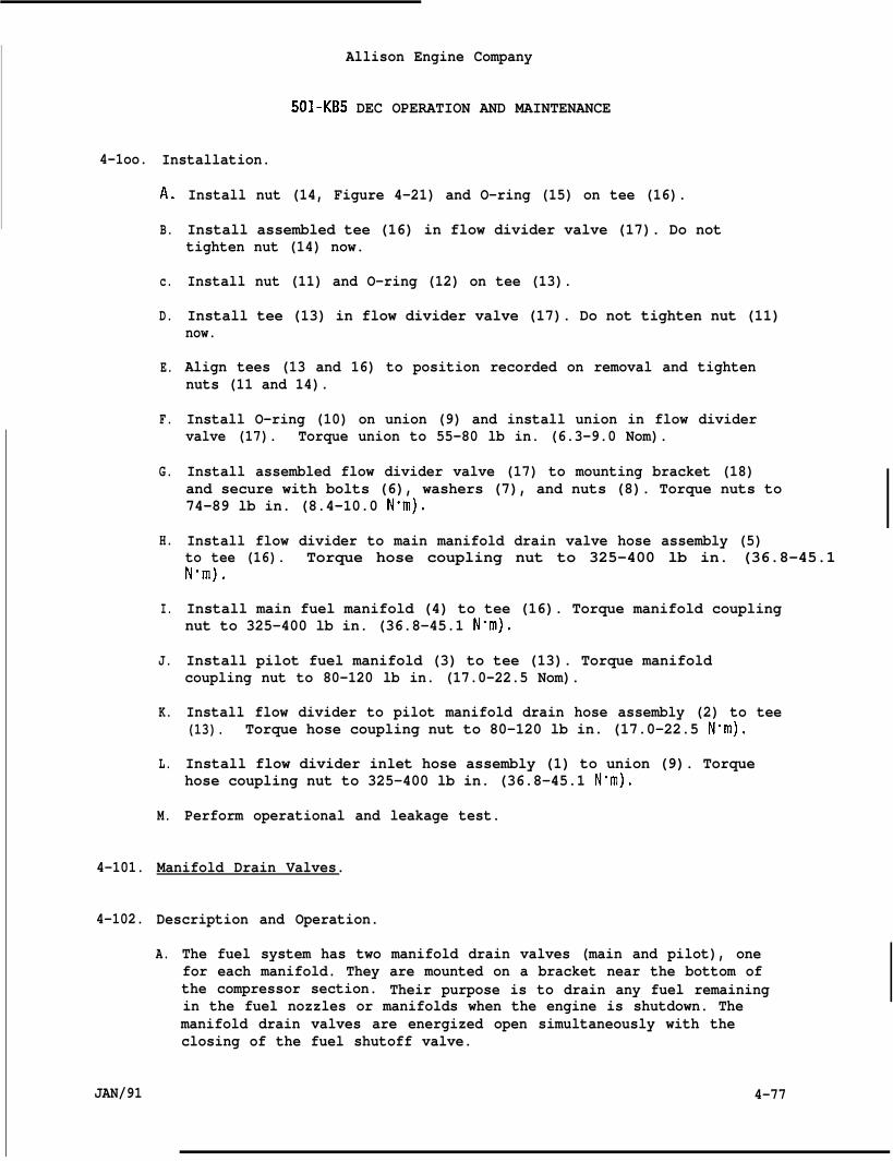
4-1oo.
4-101.
4-102.
JAN/91
Allison Engine Company
501-KB5 DEC OPERATION AND MAINTENANCE
Installation.
A.
B.
c.
D.
E.
F.
G.
H.
I.
J.
K.
L.
M.
Install nut (14, Figure 4-21) and O-ring (15) on tee (16).
Install assembled tee (16) in flow divider valve (17). Do nottighten nut (14) now.
Install nut (11) and O-ring (12) on tee (13).
Install tee (13) in flow divider valve (17). Do not tighten nut (11)now.
Align tees (13 and 16) to position recorded on removal and tightennuts (11 and 14).
Install O-ring (10) on union (9) and install union in flow dividervalve (17). Torque union to 55-80 lb in. (6.3-9.0 Nom).
Install assembled flow divider valve (17) to mounting bracket (18)and secure with bolts (6), washers (7), and nuts (8). Torque nuts to74-89 lb in. (8.4-10.0 Nom).
Install flow divider to main manifold drain valve hose assembly (5)to tee (16). Torque hose coupling nut to 325-400 lb in. (36.8-45.1Nrm).
Install main fuel manifold (4) to tee (16). Torque manifold couplingnut to 325-400 lb in. (36.8-45.1 N-m).
Install pilot fuel manifold (3) to tee (13). Torque manifoldcoupling nut to 80-120 lb in. (17.0-22.5 Nom).
Install flow divider to pilot manifold drain hose assembly (2) to tee(13). Torque hose coupling nut to 80-120 lb in. (17.0-22.5 N-m).
Install flow divider inlet hose assembly (1) to union (9). Torquehose coupling nut to 325-400 lb in. (36.8-45.1 N“m).
Perform operational and leakage test.
Manifold Drain Valves.
Description and Operation.
A. The fuel system has two manifold drain valves (main and pilot), onefor each manifold. They are mounted on a bracket near the bottom ofthe compressor section. Their purpose is to drain any fuel remainingin the fuel nozzles or manifolds when the engine is shutdown. Themanifold drain valves are energized open simultaneously with theclosing of the fuel shutoff valve.
4-77
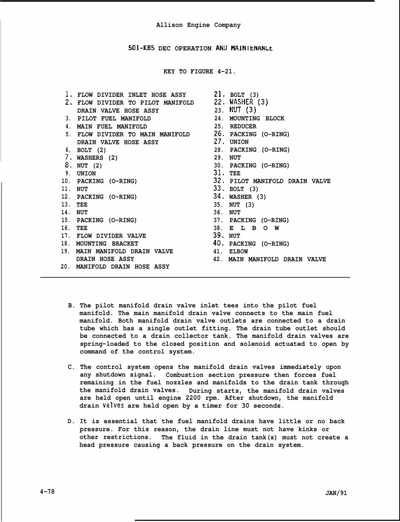
;:
3.4.5.
6.7.8.9.
10.11.12.13.14.15.16.17.18.19.
20.
Allison Engine Company
501-KB5 DEC OPERATION ANIJ MAINltNANLt
KEY TO FIGURE 4-21.
FLOW DIVIDER INLET HOSE ASSYFLOW DIVIDER TO PILOT MANIFOLDDRAIN VALVE HOSE ASSYPILOT FUEL MANIFOLDMAIN FUEL MANIFOLDFLOW DIVIDER TO MAIN MANIFOLDDRAIN VALVE HOSE ASSYBOLT (2)WASHERS (2)NUT (2)UNIONPACKING (O-RING)NUTPACKING (O-RING)TEENUTPACKING (O-RING)TEEFLOW DIVIDER VALVEMOUNTING BRACKETMAIN MANIFOLD DRAIN VALVEDRAIN HOSE ASSYMANIFOLD DRAIN HOSE ASSY
:;:23.24.25.
;!:28.29.30.
:;:
;::35.36.37.38.
:;:41.42.
BOLT (3)[ll:H:~)(3)
MOUNTING BLOCKREDUCERPACKING (O-RING)UNIONPACKING (O-RING)NUTPACKING (O-RING)TEEPILOT MANIFOLD DRAIN VALVEBOLT (3)WASHER (3)NUT (3)NUTPACKING (O-RING)E L B O WNUTPACKING (O-RING)ELBOWMAIN MANIFOLD DRAIN VALVE
B. The pilot manifold drain valve inlet tees into the pilot fuelmanifold. The main manifold drain valve connects to the main fuelmanifold. Both manifold drain valve outlets are connected to a draintube which has a single outlet fitting. The drain tube outlet shouldbe connected to a drain collector tank. The manifold drain valves arespring-loaded to the closed position and solenoid actuated to open bycommand of the control system.
C. The control system opens the manifold drain valves immediately uponany shutdown signal. Combustion section pressure then forces fuelremaining in the fuel nozzles and manifolds to the drain tank throughthe manifold drain valves. During starts, the manifold drain valvesare held open until engine 2200 rpm. After shutdown, the manifolddrain valves are held open by a timer for 30 seconds.
4-78
D. It is essential that the fuel manifold drains have little or no backpressure. For this reason, the drain line must not have kinks orother restrictions. The fluid in the drain tank(s) must not create ahead pressure causing a back pressure on the drain system.
JAN/91
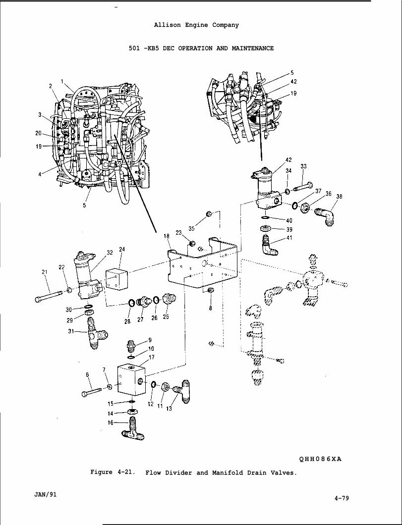
—
Allison Engine Company
501 -KB5 DEC OPERATION AND MAINTENANCE
QHH086XA
Figure 4-21. Flow Divider and Manifold Drain Valves.
JAN/91 4-79
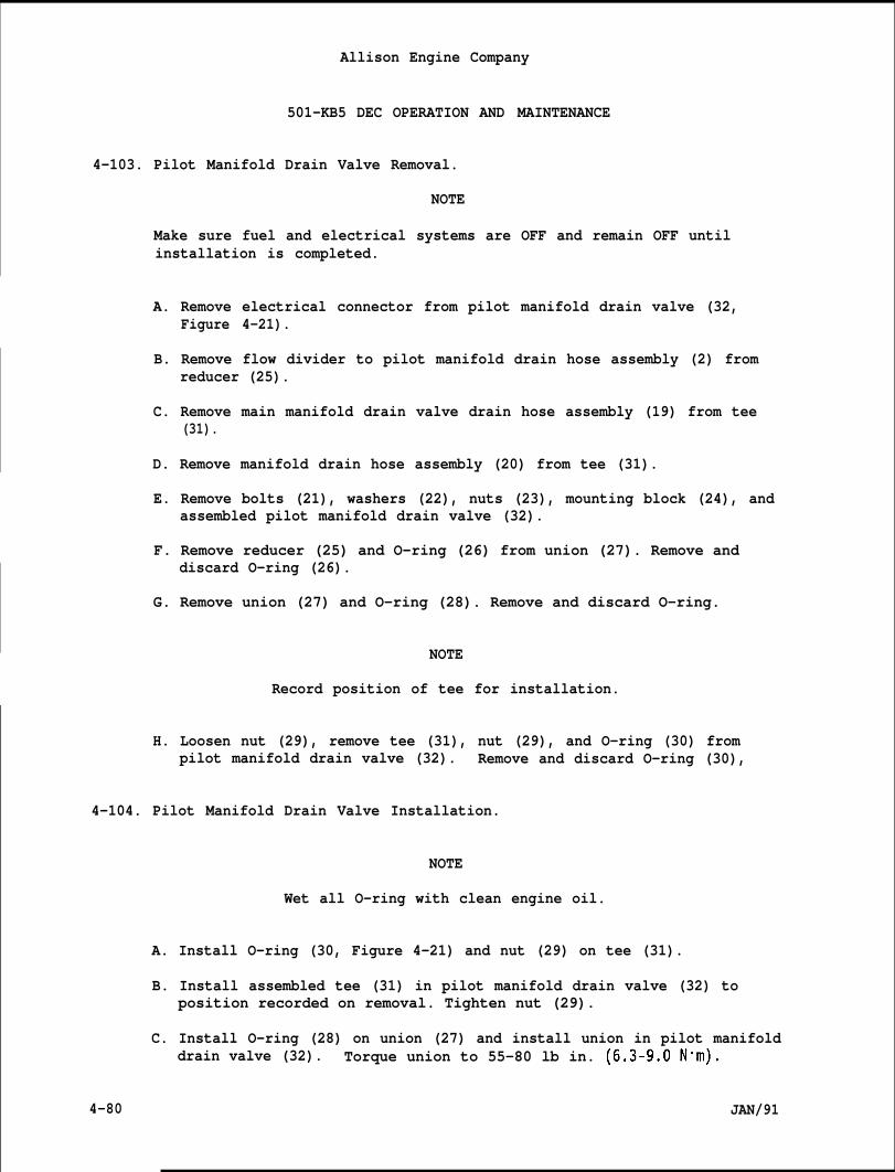
Allison Engine Company
501-KB5 DEC OPERATION AND MAINTENANCE
4-103. Pilot Manifold Drain Valve Removal.
NOTE
Make sure fuel and electrical systems are OFF and remain OFF untilinstallation is completed.
A. Remove electrical connector from pilot manifold drain valve (32,Figure 4-21).
B. Remove flow divider to pilot manifold drain hose assembly (2) fromreducer (25).
C. Remove main manifold drain valve drain hose assembly (19) from tee(31).
D. Remove manifold drain hose assembly (20) from tee (31).
E. Remove bolts (21), washers (22), nuts (23), mounting block (24), andassembled pilot manifold drain valve (32).
F. Remove reducer (25) and O-ring (26) from union (27). Remove anddiscard O-ring (26).
G. Remove union (27) and O-ring (28). Remove and discard O-ring.
NOTE
Record position of tee for installation.
H. Loosen nut (29), remove tee (31), nut (29), and O-ring (30) frompilot manifold drain valve (32). Remove and discard O-ring (30),
4-104. Pilot Manifold Drain Valve Installation.
NOTE
Wet all O-ring with clean engine oil.
A. Install O-ring (30, Figure 4-21) and nut (29) on tee (31).
B. Install assembled tee (31) in pilot manifold drain valve (32) toposition recorded on removal. Tighten nut (29).
C. Install O-ring (28) on union (27) and install union in pilot manifolddrain valve (32). Torque union to 55-80 lb in. (6.3-9.ON”m).
4-80 JAN/91
D.
E.
F.
G.
H.
I.
J.
InstallHold un”N“m).
Install
—
Allison Engine Company
501-KB5 DEC OPERATION AND MAINTENANCE
O-ring (26) on union (27) and install reducer (25) on union.on from turning and torque reducer to 55-80 lb in. (6.3-9.0
pilot manifold drain valve (32) andmountinq block (24) tomounting bracket (18), secure with bolts (21), wash~rs (22); and nuts(23). Torque nuts to 74-89 lb in. (8.4-10.0 Nom).
Install manifold drain hose assembly (20) to tee (31). Torque hose’scoupling nut to 325-400 lb in. (36.8-45.1 Nom).
Install main manifold drain valve drain hose assembly (19) to tee(31). Torque hose’s coupling nut to 325-400 lb in. (36.8-45.1N“m).
Install flow divider to pilot manifold drain hose assembly (2) toreducer (25). Hold reducer from turninq and toraue hose’s coupling
Install electrical connector to pi-
Perform an operational and leakage
nut to 325-400 lb in. (36.8-45.1 Nom). -
ot manifold drain valve (32).
test.
4-105. Main Manifold Drain Valve Removal.
NOTE
Make sure fuel and electrical system are OFF and remain OFF untilinstallation is completed.
A.
B.
c.
D.
E.
JAN/91
Remove electrical connector from main manifold drain valve (42,Figure 4-21).
Remove flow divider to main manifold drain valve hose assembly (5)from elbow (38).
Remove main manifold valve drain hose assembly (19) frommanifold drain valve (42).
Remove bolts (33), washers (34), nuts (35). and main fue”drain valve (42) -from mount{ng’bracket’(18).
NOTE
Record position of elbows for installation.
Loosen nut (36) and remove nut (36), O-ring (37), and e’main manifold drain valve (42). Remove and discard O-r
.
main
manifold
bow (38) fromng.
4-81
Allison Engine Company
501-KB5 DEC OPERATION AND MAINTENANCE
F. Loosen nut (39) and remove nut (39), O-ring (40), and elbow (41) frommain fuel manifold drain valve (42).
4-106. Main Manifold Drain Valve Installation.
NOTE
Het all O-rings with clean engine oil.
A. Install nut (39, Figure 4-21) and O-ring (40) on elbow (41).
B. Install assembled elbow (41) on main fuel manifold drain valve (42)to position recorded on removal. Tighten nut (39).
C. Install nut (36) and O-ring (37) on elbow (38).
D. Install assembled elbow (38) on main fuel manifold drain valve (42)to position recorded on removal. Tighten nut (36).
E. Install assembled main fuel manifold drain valve (42) on mountingbracket (18) and secure with bolts (33), washers (34), and nut (35),Torque nuts to 74-89 lb in. (8.4-10.0 Nom).
F. Install main manifold drain valve drain hose assembly (19) to mainmanifold drain valve (42). Torque hose coupling nut to 325-400 lbin. (36.8 -45.1 Nom).
G. Install flow divider to main manifold drain valve hose assembly (5)to main manifold drain valve (42). Torque hose coupling nut to325-400 lb in. (36.8-45.1 N*m).
H. Perform an operational and leakage test.I
4-107. Liquid Fuel Nozzle.
4-108. Description and Operation.
A. The purpose of the fuel nozzles is to deliver fuel into thecombustion liners in the correct atomized and directed manner undervariable flow and pressure conditions. Also allows inlet for waterinjection.
B. The pilot inlet is used for starting the engine and both, pilot andmain inlets, are used for normal operation of the engine.
C. The six (6) fuel nozzles are flanged mounted on a pad around thediffuser.
4-82 JAN/91
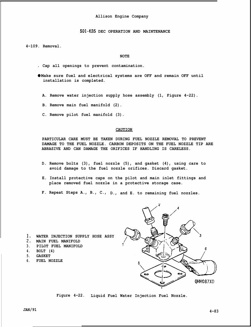
Allison Engine Company
501-KB5 DEC OPERATION AND MAINTENANCE
4-109. Removal.
NOTE
. Cap all openings to prevent contamination.
● Make sure fuel and electrical systems are OFF and remain OFF untilinstallation is completed.
A. Remove water injection supply hose assembly (1, Figure 4-22).
B. Remove main fuel manifold (2).
C. Remove pilot fuel manifold (3).
CAUTION
PARTICULAR CARE MUST BE TAKEN DURING FUEL NOZZLE REMOVAL TO PREVENTDAMAGE TO THE FUEL NOZZLE. CARBON DEPOSITS ON THE FUEL NOZZLE TIP AREABRASIVE AND CAN DAMAGE THE ORIFICES IF HANDLING IS CARELESS.
D. Remove bolts (3), fuel nozzle (5), and gasket (4), using care toavoid damage to the fuel nozzle orifices. Discard gasket.
E. Install protective caps on the pilot and main inlet fittings andplace removed fuel nozzle in a protective storage case.
F. Repeat Steps A., B., C., D., and E. to remaining fuel nozzles.
;:3.4.5.6.
4-83
WATER INJECTION SUPPLY HOSE ASSYMAIN FUEL MANIFOLDPILOT FUEL MANIFOLDBOLT (4)GASKETFUEL NOZZLE
Figure 4-22. Liquid Fuel Water Injection Fuel Nozzle.
JAN/91
Allison Engine Company
501-KB5 DEC OPERATION AND MAINTENANCE
4-110. Inspection.
CAUTION
DO NOT DISASSEMBLE FUEL NOZZLES FOR INSPECTION. DISASSEMBLY IS NOTALLOWED AT THIS MAINTENANCE LEVEL.
NOTE
Carbon deposits anywhere except around the tip and shroud indicatesleakage, which is allowed.
A.
B.
Visually inspect fornozzles.
Replacement of indiv
excessive carbon accumulation on the fuel
dual fuel nozzles is not allowed. A comDletebench test is necessary to accurately determine which fuel nhzzle(s)of the six are deficie~t. The fuel n~zzles are changed in sets of-six(6). The flow divider valve should be replaced and sent with thefuel nozzles for repair and calibration.
NOTE
Some carbon deposited around the pilot spray tip and the main jets isnormal . If there is no visible damage or hot spots in the associatedcombustion liners or turbine vanes as seen by borescope inspection, andif there are no starting problems or dark exhaust smoke, the carbon isnot interfering with the operation of the fuel nozzle and should not bedisturbed.
C. Replace or clean the fuel nozzles if excessive smoking occurs fromthe exhaust or if carbon buildup appears to be restricting ordistorting the fuel flow.
D. Warpage of the fuel nozzle air shroud or worn places through the wearcoating to the bare metal along the axial portion of the air shroudthe fuel nozzle must be replaced.
E. Any damage to the spray tip or main jets which changes fuel flowcharacteristics or to the shroud which changes air flowcharacteristics or to the internal screen which is suspected of beingclogged the fuel nozzle must be replaced.
4-111. Cleaning.
CAUTION
DO NOT DISASSEMBLE FUEL NOZZLES FOR CLEANING. DISASSEMBLY IS NOTALLOWED AT THIS MAINTENANCE LEVEL.
4-84 JAN/91
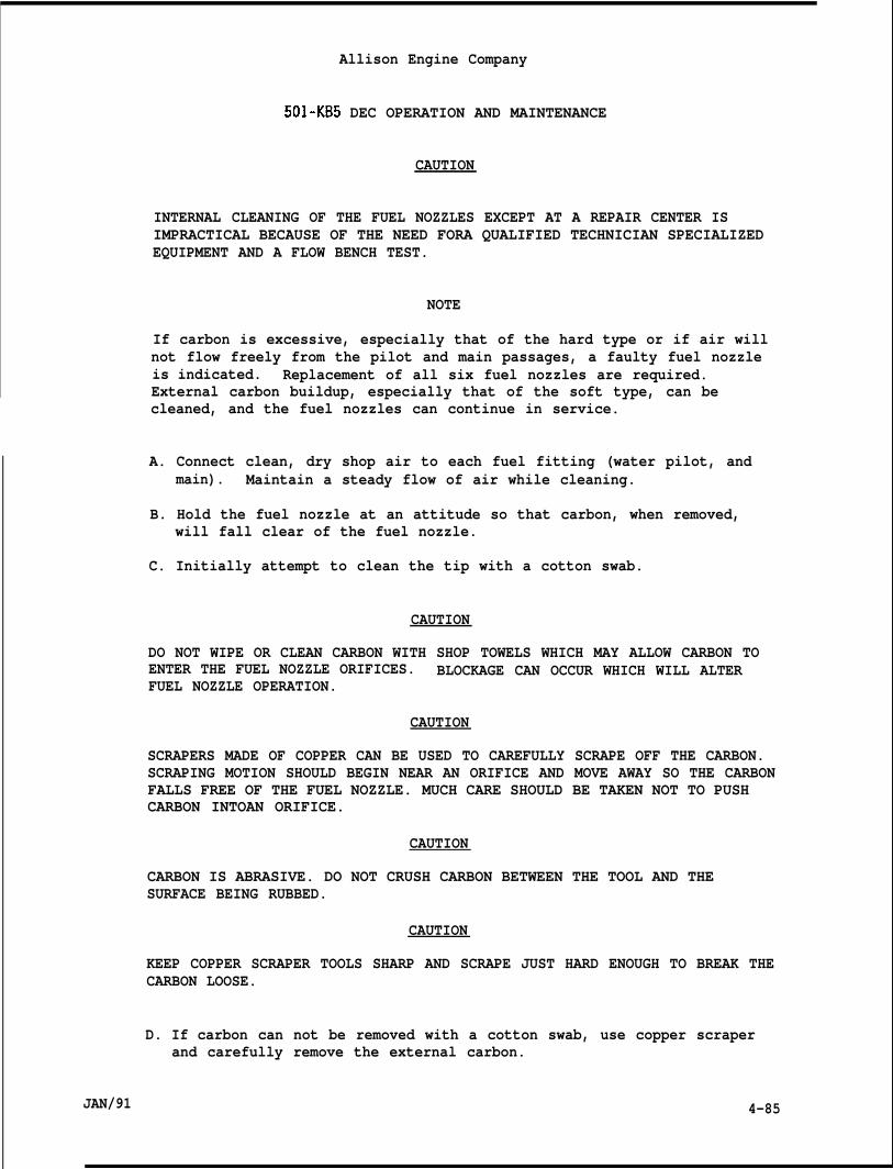
JAN/91
Allison Engine Company
501-KB5 DEC OPERATION AND MAINTENANCE
CAUTION
INTERNAL CLEANING OF THE FUEL NOZZLES EXCEPT AT A REPAIR CENTER ISIMPRACTICAL BECAUSE OF THE NEED FORA QUALIFIED TECHNICIAN SPECIALIZEDEQUIPMENT AND A FLOW BENCH TEST.
NOTE
If carbon is excessive, especially that of the hard type or if air willnot flow freely from the pilot and main passages, a faulty fuel nozzleis indicated. Replacement of all six fuel nozzles are required.External carbon buildup, especially that of the soft type, can becleaned, and the fuel nozzles can continue in service.
A. Connect clean, dry shop air to each fuel fitting (water pilot, andmain). Maintain a steady flow of air while cleaning.
B. Hold the fuel nozzle at an attitude so that carbon, when removed,will fall clear of the fuel nozzle.
C. Initially attempt to clean the tip with a cotton swab.
CAUTION
DO NOT WIPE OR CLEAN CARBON WITH SHOP TOWELS WHICH MAY ALLOW CARBON TOENTER THE FUEL NOZZLE ORIFICES. BLOCKAGE CAN OCCUR WHICH WILL ALTERFUEL NOZZLE OPERATION.
CAUTION
SCRAPERS MADE OF COPPER CAN BE USED TO CAREFULLY SCRAPE OFF THE CARBON.SCRAPING MOTION SHOULD BEGIN NEAR AN ORIFICE AND MOVE AWAY SO THE CARBONFALLS FREE OF THE FUEL NOZZLE. MUCH CARE SHOULD BE TAKEN NOT TO PUSHCARBON INTOAN ORIFICE.
CAUTION
CARBON IS ABRASIVE. DO NOT CRUSH CARBON BETWEEN THE TOOL AND THESURFACE BEING RUBBED.
CAUTION
KEEP COPPER SCRAPER TOOLS SHARP AND SCRAPE JUST HARD ENOUGH TO BREAK THECARBON LOOSE.
D. If carbon can not be removed with a cotton swab, use copper scraperand carefully remove the external carbon.
4-85
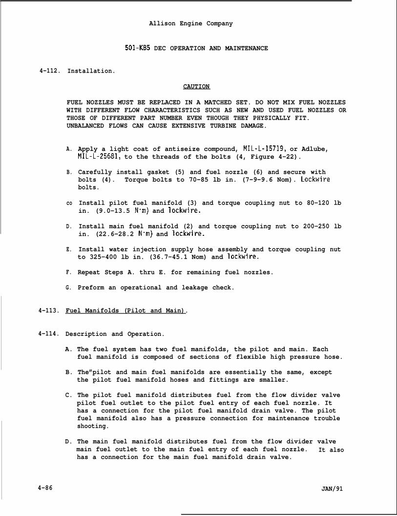
4-112.
4-113.
4-114.
4-86
Allison Engine Company
501-KB5 DEC OPERATION AND MAINTENANCE
Installation.
CAUTION
FUEL NOZZLES MUST BE REPLACED IN A MATCHED SET. DO NOT MIX FUEL NOZZLESWITH DIFFERENT FLOW CHARACTERISTICS SUCH AS NEW AND USED FUEL NOZZLES ORTHOSE OF DIFFERENT PART NUMBER EVEN THOUGH THEY PHYSICALLY FIT.UNBALANCED FLOWS CAN CAUSE EXTENSIVE TURBINE DAMAGE.
A.
B.
co
D.
E.
F.
G.
Apply a light coat of antiseize compound, MIL-L-15719, or Adlube,MIL-L-25681, to the threads of the bolts (4, Figure 4-22).
Carefully install gasket (5) and fuel nozzle (6) and secure withbolts (4). Torque bolts to 70-85 lb in. (7-9-9.6 Nom). Lockwirebolts.
Install pilot fuel manifold (3) and torque coupling nut to 80-120 lbin. (9.0-13.5 N”m) and lockwire.
Install main fuel manifold (2) and torque coupling nut to 200-250 lbin. (22.6-28.2 N“m) and lockwire.
Install water injection supply hose assembly and torque coupling nutto 325-400 lb in. (36.7-45.1 Nom) and lockwire.
Repeat Steps A. thru E. for remaining fuel nozzles.
Preform an operational and leakage check.
Fuel Manifolds (Pilot and Main).
Description and Operation.
A. The fuel system has two fuel manifolds, the pilot and main. Eachfuel manifold is composed of sections of flexible high pressure hose.
B. The”pilot and main fuel manifolds are essentially the same, exceptthe pilot fuel manifold hoses and fittings are smaller.
C. The pilot fuel manifold distributes fuel from the flow divider valvepilot fuel outlet to the pilot fuel entry of each fuel nozzle. Ithas a connection for the pilot fuel manifold drain valve. The pilotfuel manifold also has a pressure connection for maintenance troubleshooting.
D. The main fuel manifold distributes fuel from the flow divider valvemain fuel outlet to the main fuel entry of each fuel nozzle. It alsohas a connection for the main fuel manifold drain valve.
JAN/91
Allison Engine Company
501-KB5 DEC OPERATION AND MAINTENANCE
4-115. Removal and Installation.
A. Remove the fuel manifolds from the flow divider valve outlets.
NOTE
Cap all openings to prevent contamination.
B. Remove the fuel manifolds at each fuel nozzle. The smallerconnection is the pilot, the larger is the main.
C. Disconnect any hoses, clamps, and connectors as necessary to removethe fuel manifolds.
D. Installation is the reverse of the removal procedure
E. Be sure to connect any hoses, clamps, and connectors that wereremoved.
F. Perform an operational and leakage test, being sure to inspect allitems disturbed for accessibility.
4-116. DUAL ENTRY FUEL SYSTEM.
4-117. DESCRIPTION.
A. The dual entry fuel system consists of all the components necessaryto receive fuel, boost it to the necessary pressure, and supply it inthe necessary metered volume and pressure to the combustion sectionof the engine.
B. Components of the fuel system are mounted in various locations on ornear the engine. The components are:
1. Fuel pump.2. Low pressure (LP) fuel filter with differential pressure switch.3. High pressure (HP) fuel filter.4. Fuel pump paralleling valve.5. Pressure relief valve.6. Fuel metering valve.7. Fuel shutoff valve.8. Flow divider valve.9. Pilot and main fuel man10. Fuel nozzles.11. Manifold drain valves.12. Burner drain valves.13. Lines and hoses.
C. The approved liquid fuels al
JAN/91
folds.
e listed in Table 4-1.
4-87
4-118.
4-119.
4-120.
4-88
Allison Engine Company
501-KB5 DEC OPERATION AND MAINTENANCE
OPERATION.
A. During engine operation, fuel entersinto the boost (centrifugal) elementThe boosted fuel flows from the fuelreturns throuqh internal Passa9es of
the fuel pump inlet and passesof the engine driven fuel pump.pump to the LP fuel filter thenthe HP fuel filter to the gear
elements of t~e fuel pump. The two gear elements of the fuel pumpnormally operate in series but operate in parallel for starting. Thehigh pressure (HP) fuel flows from the fuel pump through the HP fuelfilter. The pressure relief valve limits fuel pressure to 500 psi(3445 kPa) and will bypass the excess fuel back to the fuel pumpinlet. The HP fuel is delivered to the fuel metering valve. Thefuel metering valve, by direction of the control system, meters thefuel required and bypasses the remaining fuel. Bypass fuel isreturned to the fuel pump inlet through a passage in the HP fuelfilter. The metered fuel passes through the fuel shutoff valve to theflow divider valve, which directs the meter fuel to the pilot and/ormain fuel manifolds which distributes the fuel to the six fuelnozzles. A schematic of the fuel system is shown in Figure 4-23.
B. The engine is shutdown by closing the fuel shutoff valve. Fuelremaining in the fuel nozzles, pilot and main manifolds, andcombustion section is automatically drained from the engine by theopening of the manifold drain valves and burner drain valves.
CAUTION
FUEL DRAINAGE ACCUMULATION IS APPROXIMATELY 8.0 GALLONS (30.4 LITERS)PER 100 ENGINE STARTS. THE DRAIN COLLECTOR TANK SHOULD NOT BE ALLOWEDTO FILL AS THIS RESTRICTS THE CORRECT FUNCTIONING OF THE FUEL MANIFOLDDRAIN SYSTEM.
FUEL PUMP.
NOTE
For Description, Operation, and Maintenance refer to Paragraphs 4-39 to4-43.
HIGH PRESSURE (HP) FUEL FILTER.
NOTE
For Description, Operation, and Maintenance refer to Paragraphs 4-44 to4-50.
JAN/91
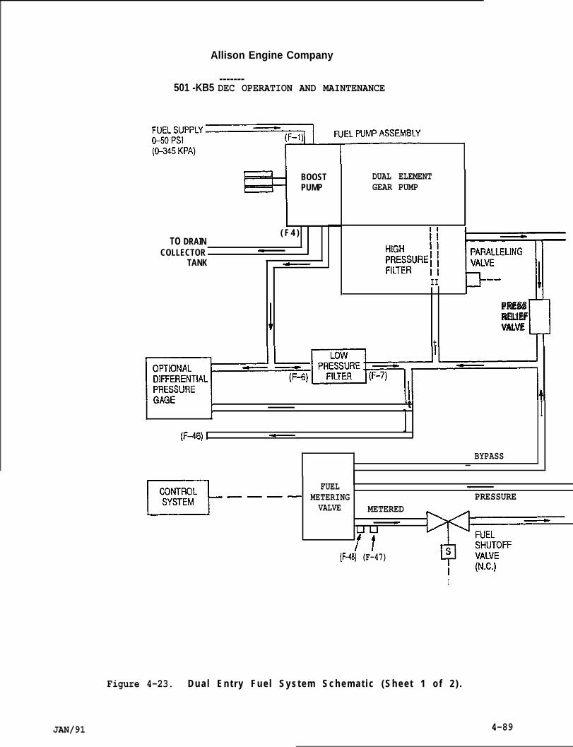
Allison Engine Company
-------501 -KB5 DEC OPERATION AND MAINTENANCE
=J~~7EL’uM’AssEMBLy7 BOOST
PUMP
1
TO DRAIN( F 4 )
COLLECTOR -TANK ~
/
DUAL ELEMENTGEAR PUMP
Ei%uR’l EF’EL’NGlsII - -
“()+PRESSRELIEF
tVALVE
Unul-
1 ‘t I(F+ I ~
BYPASS—
——EEF---- FUEL .
METERING PRESSUREVALVE METERED
UUe
/t(F+) (F-47)
II
JAN/91
Figure 4-23. D u a l E n t r y F u e l S y s t e m S c h e m a t i c ( S h e e t 1 o f 2 ) .
4-89
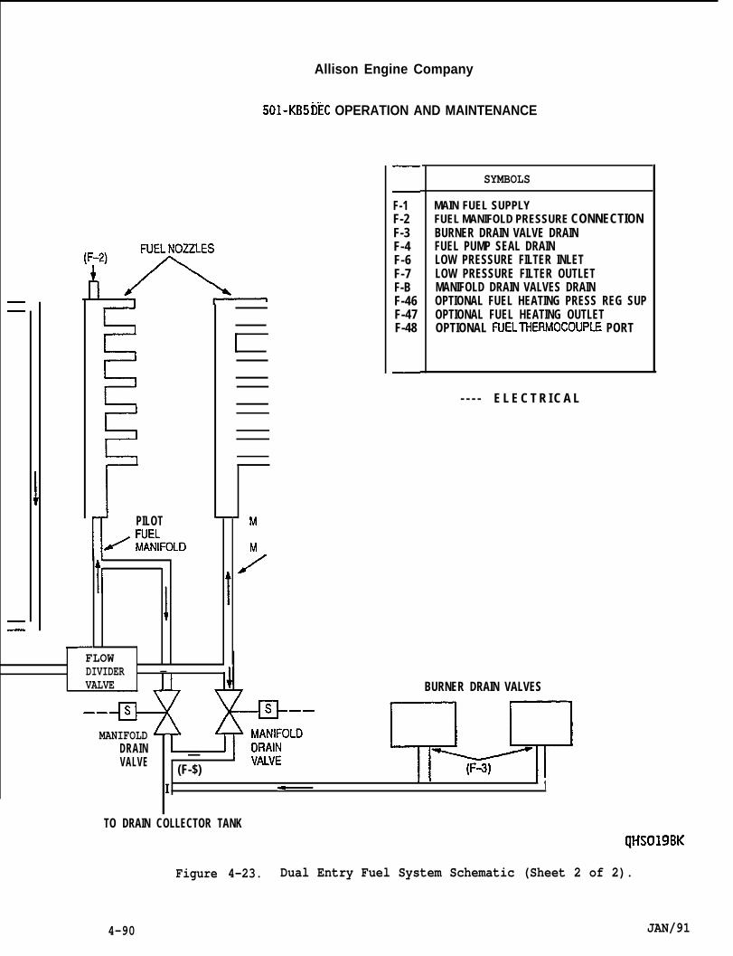
Allison Engine Company
501-KB5 tiEC OPERATION AND MAINTENANCE
II PILOT
K iiRiFoL13
F-1F-2F-3F-4F-6F-7F-BF-46F-47F-48
SYMBOLS
MAIN FUEL SUPPLYFUEL MANIFOLD PRESSURE CONNECTIONBURNER DRAIN VALVE DRAINFUEL PUMP SEAL DRAINLOW PRESSURE FILTER INLETLOW PRESSURE FILTER OUTLETMANIFOLD DRAIN VALVES DRAINOPTIONAL FUEL HEATING PRESS REG SUPOPTIONAL FUEL HEATING OUTLETOPTIONAL FLJELTHERMOCOUPLE PORT
t’ IFLOWDIVIDER —VALVE
——
MANIFOLDDRAINVALVE
I
—(F-$)
< I 1 !1
- - - - E L E C T R I C A L
BURNER DRAIN VALVES
TO DRAIN COLLECTOR TANKQHS019BK
Figure 4-23. Dual Entry Fuel System Schematic (Sheet 2 of 2).
4-90 JAN/91
Allison Engine Company
501-KB5 DEc OPERATION AND MAINTENANCE
4-121.
4-122.
4-123.
4-124.
4-125.
4-126.
4-127.
PARALLELING VALVE.
NOTE
For Description, Operation, and Maintenance refer to Paragraphs 4-51 to4-54.
LOW PRESSURE (LP) FUEL FILTER.
NOTE
For Description, Operation, and Maintenance refer to Paragraphs 4-55 to4-62.
PRESSURE RELIEF VALVE.
NOTE
For Description, Operation, and Maintenance refer to Paragraphs 4-63 to4-66.
FUEL METERING VALVE (FMV).
NOTE
For Description, Operation, and Maintenance refer to Paragraphs 4-67 to4-70.
FUEL SHUTOFF VALVE.
NOTE
For Description, Operation, and Maintenance refer to Paragraphs 4-71 to4-75.
FLOW DIVIDER VALVE.
NOTE
For Description, Operation, and Maintenance refer to Paragraphs 4-96 to4-1oo.
BURNER DRAIN VALVES.
NOTE
For Description, Operation, and Maintenance refer to Paragraphs 4-81 to4-86.
JAN/91 4-91
IAllison Engine Company
501-KB5 DEC OPERATION AND MAINTENANCE
4-128. FUEL LINES AND HOSES.
A.
B.
All flexible fuel lines furnished with the engine have an inner coreof teflon, protected by one or more layers of protective material anda braided metal sheath. These hoses are very durable and not proneto deterioration, however they are susceptible to damage from sharpbends, kinks, twists and crushing. Evidence of such damage to theteflon core is difficult to detect. If damage is suspected, the hosemust be replaced or pressure tested.
All fuel lines and hoses should be inspected regularly for:
1. Leaks2. Chaffing3. Wear -
4. Damage coupling nuts (connectors)5. Kinks6. Twisting7. Swelling8. Crushing
4-129 FUEL MANIFOLDS (PILOT AND MAIN).
NOTE
For Descri~tion, O~eration, and Maintenance refer to Paragraphs 4-113to 4-115. - - - -
NOTE
Cap all openings to prevent contamination.
4-130. FUEL NOZZLES (DUAL ENTRY).
4-131. Descri~tion and O~eration.
A. The fuel nozzles are called dualconnections, a pilot and main in”
entry because they have two inletet.
B. The dual entry system is more resistance against coking andcontamination when using lower grade fuels. This is done by a coo”operating nozzle design with larger purging passages, the use of aflow div;der valve, aid a high flow rnanifoid”drai~ valves.
C. The pilot fuel inlet is used for starting the engine and both,and main, fuel inlets are used for normal operation of the eng”
D. The six (6) dual entry fuel nozzles are flange mounted on padsthe diffuser.
er
pilotne.
around
4-92 JAN/91
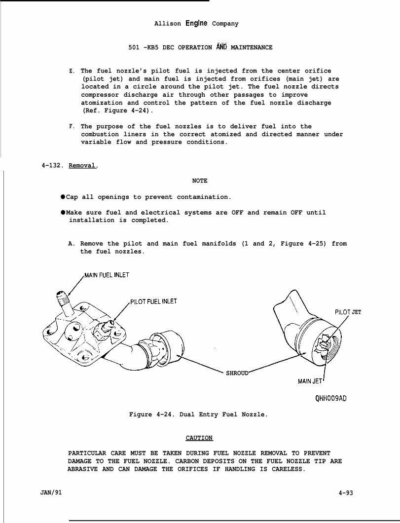
E.
F.
Allison Engine Company
501 -KB5 DEC OPERATION MD MAINTENANCE
The fuel nozzle’s pilot fuel is injected from the center orifice(pilot jet) and main fuel is injected from orifices (main jet) arelocated in a circle around the pilot jet. The fuel nozzle directscompressor discharge air through other passages to improveatomization and control the pattern of the fuel nozzle discharge(Ref. Figure 4-24).
The purpose of the fuel nozzles is to deliver fuel into thecombustion liners in the correct atomized and directed manner undervariable flow and pressure conditions.
4-132. Removal.
NOTE
● Cap all openings to prevent contamination.
● Make sure fuel and electrical systems are OFF and remain OFF untilinstallation is completed.
A. Remove the pilot and main fuel manifolds (1 and 2, Figure 4-25) fromthe fuel nozzles.
/
MAINFUELINLET
SHROUDMAINJET1
QHHO09AD
Figure 4-24. Dual Entry Fuel Nozzle.
CAUTION
PARTICULAR CARE MUST BE TAKEN DURING FUEL NOZZLE REMOVAL TO PREVENTDAMAGE TO THE FUEL NOZZLE. CARBON DEPOSITS ON THE FUEL NOZZLE TIP AREABRASIVE AND CAN DAMAGE THE ORIFICES IF HANDLING IS CARELESS.
JET
JAN/91 4-93
Allison Engine Company
501-KB5 DEC OPERATION AND MAINTENANCE
B. Remove bolts (3), fuel nozzle (5), and gasket (4), using care toavoid damage to the fuel nozzle orifices. Discard gasket.
C. Install protective caps onplace removed fuel nozzle
D. Repeat Steps 1., 2., and 3
4-133. Inspection.
the pilot and main inlet fittings andn a protective storage case.
to remaining fuel nozzles.
CAUTION
DO NOT DISASSEMBLE FUEL NOZZLES FOR INSPECTION. DISASSEMBLY IS NOTALLOWED AT THIS MAINTENANCE LEVEL.
NOTE
Carbon deposits anywhere except around the tip andleakage, which is allowed.
A. Visually inspect for excessive carbon accumulatnozzles.
shroud indicates
on on the fuel
B. Replacement of individual fuel nozzles is not allowed. A completebench test is necessary to accurately determine which fuel nozzle(s)of the six are deficient. The fuel nozzles are changed in sets of six(6). The flow divider valve should be replaced and sent with thefuel nozzles for repair and calibration.
NOTE
Some carbon deposited around the pilot spray tip and the main jets isnormal. If there is no visible damage or hot spots in the associatedcombustion liners or turbine vanes as seen by borescope inspection, andif there are no starting problems or dark exhaust smoke, the carbon isnot interfering with the operation of the fuel nozzle and should not bedisturbed.
C. Replace or clean the fuel nozzles if excessive smokincl occurs fromthe exhaust or if carbon buildup appearsdistorting the fuel flow.
D. Warpage of the fuel nozzle air shroud orcoating to the bare metal along the axia”the fuel nozzle must be replaced.
to be restri~ting or
worn places through the wearportion of the air shroud
4-94 JAN/91
4-134.
Allison Engine Company
501 -KB5 DEC OPERATION AND MAINTENANCE
E. Any damage to the spray tip or main jets which changes fuel flowcharacteristics or to the shroud which changes air flowcharacteristics or to the internal screen which is suspected of beingclogged the fuel nozzle must be replaced.
Cleaninq.
CAUTION
DO NOT DISASSEMBLE FUEL NOZZLES FOR CLEANING. DISASSEMBLY IS NOTALLOWED AT THIS MAINTENANCE LEVEL.
CAUTION
INTERNAL CLEANING OF THE FUEL NOZZLES EXCEPT AT A REPAIR CENTER ISIMPRACTICAL BECAUSE OF THE NEED FOR A QUALIFIED TECHNICIAN SPECIALIZEDEQUIPMENT AND A FLOW BENCH TEST.
NOTE
If carbon is excessive, especially that of the hard type or if air willnot flow freely from the pilot and main passages, a faulty fuel nozzleis indicated. Replacement of all six fuel nozzles are required.External carbon buildup, especially that of the soft type, can becleaned, and the fuel nozzles can continue in service.
A. Connect clean, dry shop air to each fuel inlet fitting (pilot andmain). Maintain a steady flow of air while cleaning.
B. Hold the fuel nozzle at an attitude so that carbon, when removed,will fall clear of the fuel nozzle.
C. Initially attempt to clean the tip with a cotton swab.
CAUTION
DO NOT WIPE OR CLEAN CARBON WITH SHOP TOWELS WHICH MAY ALLOW CARBON TOENTER THE FUEL NOZZLE ORIFICES. BLOCKAGE CAN OCCUR WHICH WILL ALTERFUEL NOZZLE OPERATION.
CAUTION
SCRAPERS MADE OF COPPER CAN BE USED TO CAREFULLYSCRAPING MOTION SHOULD BEGIN NEAR AN ORIFICE ANDFALLS FREE OF THE FUEL NOZZLE. MUCH CARE SHOULDCARBON INTOAN ORIFICE.
JAN/91
SCRAPE OFF THE CARBON.MOVE AWAY SO THE CARBONBE TAKEN NOT TO PUSH
4-95
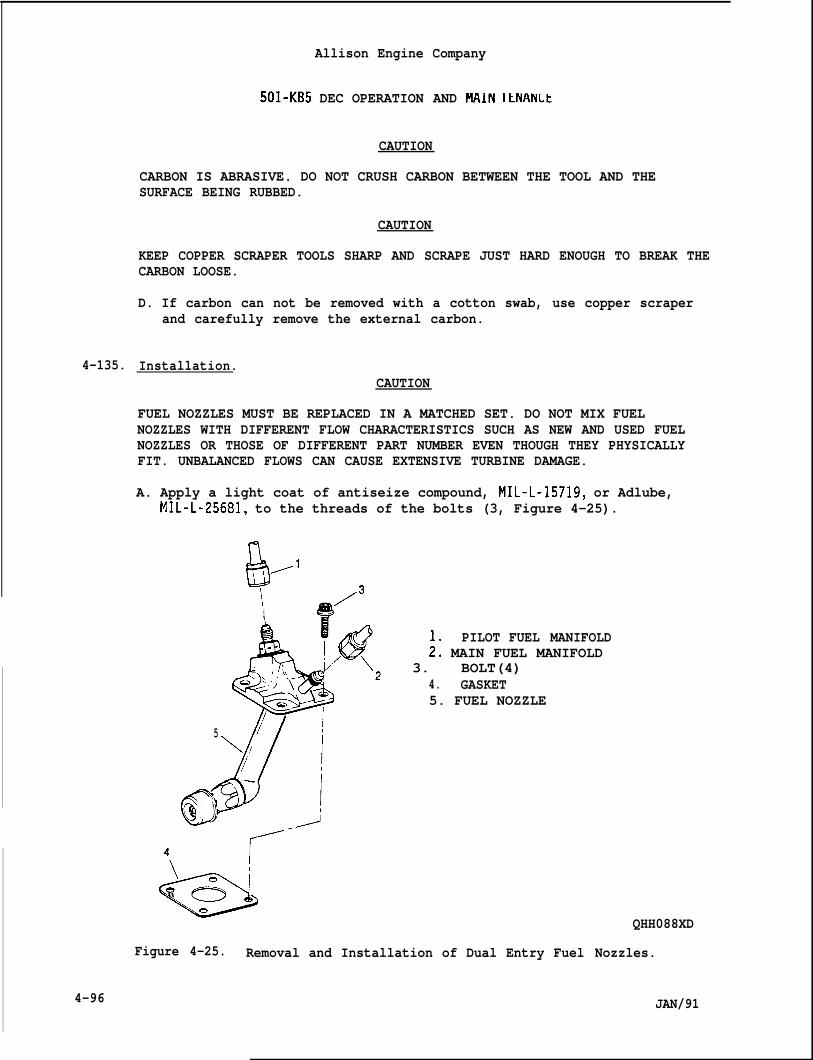
4-135.
4-96
Allison Engine Company
501-KB5 DEC OPERATION AND MAIN ILNANLt
CAUTION
CARBON IS ABRASIVE. DO NOT CRUSH CARBON BETWEEN THE TOOL AND THESURFACE BEING RUBBED.
CAUTION
KEEP COPPER SCRAPER TOOLS SHARP AND SCRAPE JUST HARD ENOUGH TO BREAK THECARBON LOOSE.
D. If carbon can not be removed with a cotton swab, use copper scraperand carefully remove the external carbon.
Installation.CAUTION
FUEL NOZZLES MUST BE REPLACED IN A MATCHED SET. DO NOT MIX FUELNOZZLES WITH DIFFERENT FLOW CHARACTERISTICS SUCH AS NEW AND USED FUELNOZZLES OR THOSE OF DIFFERENT PART NUMBER EVEN THOUGH THEY PHYSICALLYFIT. UNBALANCED FLOWS CAN CAUSE EXTENSIVE TURBINE DAMAGE.
A. Apply a light coat of antiseize compound, MIL-L-15719, or Adlube,MIL-L-25681, to the threads of the bolts (3, Figure 4-25).
ill/1
i
PILOT FUEL MANIFOLD~: MAIN FUEL MANIFOLD
* 3. BOLT(4)4. GASKET5. FUEL NOZZLE
5
\f
b“ 6
0QHH088XD
Figure 4-25. Removal and Installation of Dual Entry Fuel Nozzles.
JAN/91
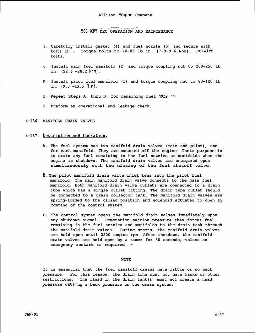
4-136.
4-137.
JAN/91
B.
c.
D.
E.
F.
Allison Engine Company
. . . ----- . —-— .—. —501-KB5 DEC OPERATION AND MAINTENANCE
Carefully install gasket (4) and fuel nozzle (5) and secure withbolts (3) . Torque bolts to 70-85 lb in. (7-9-9.6 Nom). Lockwirebolts.
Install main fuel manifold (2) and torque coupling nut to 200-250 lbin. (22.6 -28.2 Nom).
Install pilot fuel manifold (1) and torque coupling nut to 80-120 lbin. (9.0 -13.5 Nom).
Repeat Steps A. thru D. for remaining fuel nozz”
Preform an operational and leakage check.
es.
MANIFOLD DRAIN VALVES.
Descri~tion and O~eration.
A. The fuel system has two manifold drain valves (main and pilot), onefor each manifold. They are mounted off the engine. Their purpose isto drain any fuel remaining in the fuel nozzles or manifolds when theengine is shutdown. The manifold drain valves are energized opensimultaneously with the closing of the fuel shutoff valve.
B, The pilot manifold drain valve inlet tees into the pilot fuelmanifold. The main manifold drain valve connects to the main fuelmanifold. Both manifold drain valve outlets are connected to a draintube which has a single outlet fitting. The drain tube outlet shouldbe connected to a drain collector tank. The manifold drain valves arespring-loaded to the closed position and solenoid actuated to open bycommand of the control system.
C. The control system opens the manifold drain valves immediately uponany shutdown signal. Combustion section pressure then forces fuelremaining in the fuel nozzles and manifolds to the drain tank throughthe manifold drain valves. During starts, the manifold drain valvesare held open until 2200 engine rpm. After shutdown, the manifolddrain valves are held open by a timer for 30 seconds, unless anemergency restart is required. -
NOTE
It is essential that the fuel manifold drains have little or no backpressure. For this reason, the drain line must not have kinks or otherrestrictions.pressure caus”
The fluid in the drain tank(s) must not create a headng a back pressure on the drain system.
4-97
Allison Engine Company
501 -KB5 DEC OPERATION AND MAINTENANCE
4-138. Removal.
NOTE
. Make sure fuel and electrical systems are OFF and remain OFF untilinstallation is completed.
● Refer to OEM Manual for removal.
4-139. Installation.
NOTE
Refer to OEM Manual for installation.
4-140. DUAL ENTRY FUEL WATER INJECTION SYSTEM.
4-141. Description and Operation.
A. Water injection is used to cool the combustion flame temperature ofthe engine reducing exhaust emissions.
B. Requirements for the water injection system is a packaged waterinjection system, a check valve, and dual fuel nozzles replaces thedual entry fuel nozzles (Ref. Figure 4-20).
C. For Maintenance reter to OEM’s Manual(s).
D. For dual fuel nozzles’ description, operation, and maintenance referto Paragraphs 4-107 through 4-112.
4-142. DUAL FUEL SYSTEM.
4-143. DESCRIPTION AND OPERATION.
A. The dual fuel system will permit normal engine operation on eithergaseous fuel or liquid fuel.
B. The control system meters either gaseous fuel or liquid fuel and willallow making a crossover from one fuel system to the other fuelsystem without shutting down the engine (Ref. Figure 4-26).
C. The dual fuel system is an explosion proof system and many of thedual fuel system components are not mounted on the engine.
D. Some of the normal engine components are mounted off engine on aremote RAFT and electrical motor driven liquid fuel pump.
4-98 JAN/91
4-144.
4-145.
4-146.
●
●
JAN/91
Allison Engine Company
501-KB5 DEC OPERATION AND MAINTENANCE
E. Optional packaged water injection system may be installed.
F. The dual fuel system liquid fuel will be covered in Paragraphs 4-144to 4-212.
G. The dual fuel system gaseous fuel will be covered in Paragraphs 4-213to 4-236.
LOW PRESSURE (LP) FUEL FILTER ASSEMBLY.
Descrir)tion and ODeration.
A. The purpose of the LP fuel filter assembly is to filter incomingliquid fuel. Normal filtration is 10 microns, 20 micron absolutethrough a paper pleated filter.
B. The filter element should be changed if the pressure differentialacross the filter element is more than 5 psid (34.5 kPad).
C. The LP fuel filter assembly is mounted off the engine with liquidfuel pump and HP filter assembly as an assembly.
Filter Element Removal.
NOTE
Make sure fuel and electrical systems are OFF and remain OFF untilinstallation is completed.
Provide containers to catch fuel drainage and cap all openings toprevent contamination.
A. Remove case (17, Figure 4-27), spring (18), filter element (19)gasket (20) and O-ring (21) from head assembly (22). Discard gasketand O-ring.
NOTE
Filter element may required to send a Major Repair Center ifcontamination is found for further investigation. If required, placefilter element in a clean plastic bag.
B. Inspect filter element (19) and case (17) for contamination.
C. If required, discard filter element (19) after inspection.
4-99
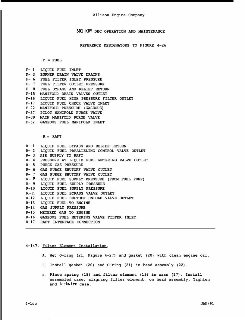
Allison Engine Company
501-KB5 DEC OPERATION AND MAINTENANCE
F- 1F- 3F- 6F- 7F- 8F-15F-16F-17F-22F-37F-39F-52
R- 1R- 2R- 3R- 4R- 5R- 6R- 7R- 8R- 9R-10R-nR-12R-13R-14R-15R-16R-17
REFERENCE DESIGNATORS TO FIGURE 4-26
F = FUEL
LIQUID FUEL INLETBURNER DRAIN VALVE DRAINSFUEL FILTER INLET PRESSUREFUEL FILTER OUTLET PRESSUREFUEL BYPASS AND RELIEF RETURNMANIFOLD DRAIN VALVES OUTLETLIQUID FUEL HIGH PRESSURE FILTER OUTLETLIQUID FUEL CHECK VALVE INLETMANIFOLD PRESSURE (GASEOUS)PILOT MANIFOLD PURGE VALVEMAIN MANIFOLD PURGE VALVEGASEOUS FUEL MANIFOLD INLET
R = RAFT
LIQUID FUEL BYPASS AND RELIEF RETURNLIQUID FUEL PARALLELING CONTROL VALVE OUTLETAIR SUPPLY TO RAFTPRESSURE AT LIQUID FUEL METERING VALVE OUTLETPURGE GAS PRESSUREGAS PURGE SHUTOFF VALVE OUTLETGAS PURGE SHUTOFF VALVE OUTLETLIQUID FUEL SUPPLY PRESSURE (FROM FUEL PUMP)LIQUID FUEL SUPPLY PRESSURELIQUID FUEL SUPPLY PRESSURELIQUID FUEL BYPASS VALVE OUTLETLIQUID FUEL SHUTOFF UNLOAD VALVE OUTLETLIQUID FUEL TO ENGINEGAS SUPPLY PRESSUREMETERED GAS TO ENGINEGASEOUS FUEL METERING VALVE FILTER INLETRAFT INTERFACE CONNECTION
4-147. Filter Element Installation.
A.
B.
c.
4-1oo
Wet O-ring (21, Figure 4-27) and gasket (20) with clean engine oil.
Install gasket (20) and O-ring (21) in head assembly (22).
Place spring (18) and filter element (19) in case (17). Installassembled case, aligning filter element, on head assembly. Tightenand lockwire case.
JAN/91
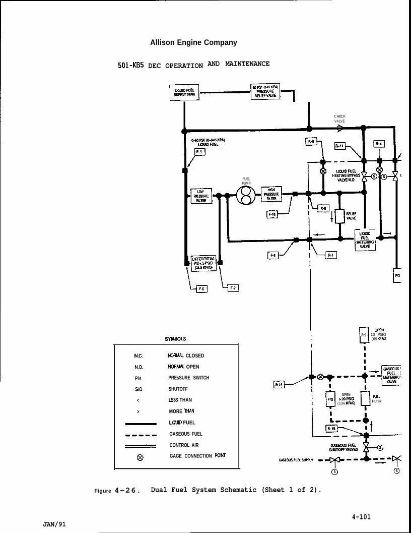
Allison Engine Company
501-KB5 DEC OPERATION AND MAINTENANCE
mLJOUID FUELSUPPLY TANK
_~17
L
SYMEOLS
I CHECKVALVE
El/
nwL& _FILlsn
WIl
..—
FUELPUMP
I
-El
I
N.C.
N.O.
P/s
SIo
<
>
NORMAL CLOSED
NORMA OPEN
PREsSURE SWITCH
SHUTOFF
LESS THAN
MORE 11’w
LIOUID FUEL
GASEOUS FUEL
CONTROL AIR
GAGE CONNECTION POINT
El1
c1 OPSNPG > 10 PSIG
(69 $7AGl
dR-14 , ---{+5?
~y Q
OPENP/s
WEL>20P9G(136 KPAGl FILTER
G4SELIS FUEL SUPRV
Figure 4-26. Dual Fuel System Schematic (Sheet 1 of 2).
4-101JAN/91
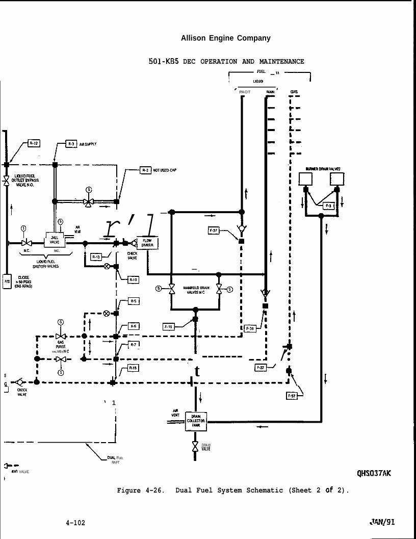
Allison Engine Company
DEC OPERATION AND MAINTENANCE
I ‘“” -“ ~
501-KB5
QHS037AK
I LIOIAD
‘ PAOT MAJN ‘0-
1:-
r-*-&.
t“r-/= fm’”s”pp”
[
it
?
n “IQ --l
‘ , J,=. r’l-
ttI
— I
N.C. NC. . I ‘ 1 ~~I~Ea”lSNUTOFF VAMS
I
-1F.15i
--0---kEl---%7 4/.If -
VALVES N.C.
-t=
6-- -- G--- -----------T t------- -m i /:
1 R.15 w+I @ h
1sIG +-&---------- d--.. ------4.. - . . ..---.-. A\
‘ 1\El-
II
—- J\ow FUEL
RAFT II DRAWVALVE
———
a--Wl VALVE
)
Figure 4-26. Dual Fuel System Schematic (Sheet 2 of 2).
4-102
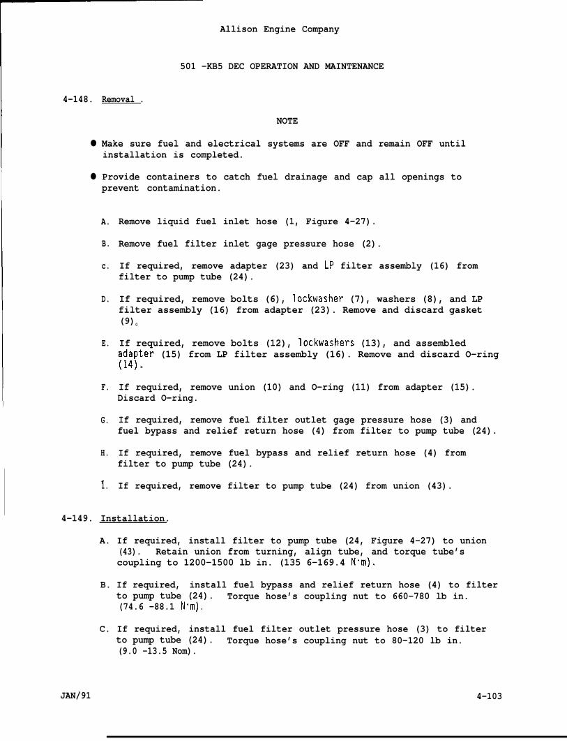
4-148.
●
●
Allison Engine Company
501 -KB5 DEC OPERATION AND MAINTENANCE
Removal .
NOTE
Make sure fuel and electrical systems are OFF and remain OFF untilinstallation is completed.
Provide containers to catch fuel drainage and cap all openings toprevent contamination.
A.
B.
c.
D.
E.
F.
G.
H.
.
Remove liquid fuel inlet hose (1, Figure 4-27).
Remove fuel filter inlet gage pressure hose (2).
If required, remove adapter (23) and LP filter assembly (16) fromfilter to pump tube (24).
If required, remove bolts (6), lockwasher (7), washers (8), and LPfilter assembly (16) from adapter (23). Remove and discard gasket(9)0
If required, remove bolts (12), lockwashers (13), and assembled~~~~ter (15) from LP filter assembly (16). Remove and discard O-ring
.
If required, remove union (10) and O-ring (11) from adapter (15).Discard O-ring.
If required, remove fuel filter outlet gage pressure hose (3) andfuel bypass and relief return hose (4) from filter to pump tube (24).
If required, remove fuel bypass and relief return hose (4) fromfilter to pump tube (24).
If required, remove filter to pump tube (24) from union (43).1.
4-149. Installation.
A. If required, install filter to pump tube (24, Figure 4-27) to union(43). Retain union from turning, align tube, and torque tube’scoupling to 1200-1500 lb in. (135 6-169.4 N“m).
B. If required, install fuel bypass and relief return hose (4) to filterto pump tube (24). Torque hose’s coupling nut to 660-780 lb in.(74.6 -88.1 N+m),
C. If required, install fuel filter outlet pressure hose (3) to filterto pump tube (24). Torque hose’s coupling nut to 80-120 lb in.(9.0 -13.5 Nom).
JAN/91 4-103
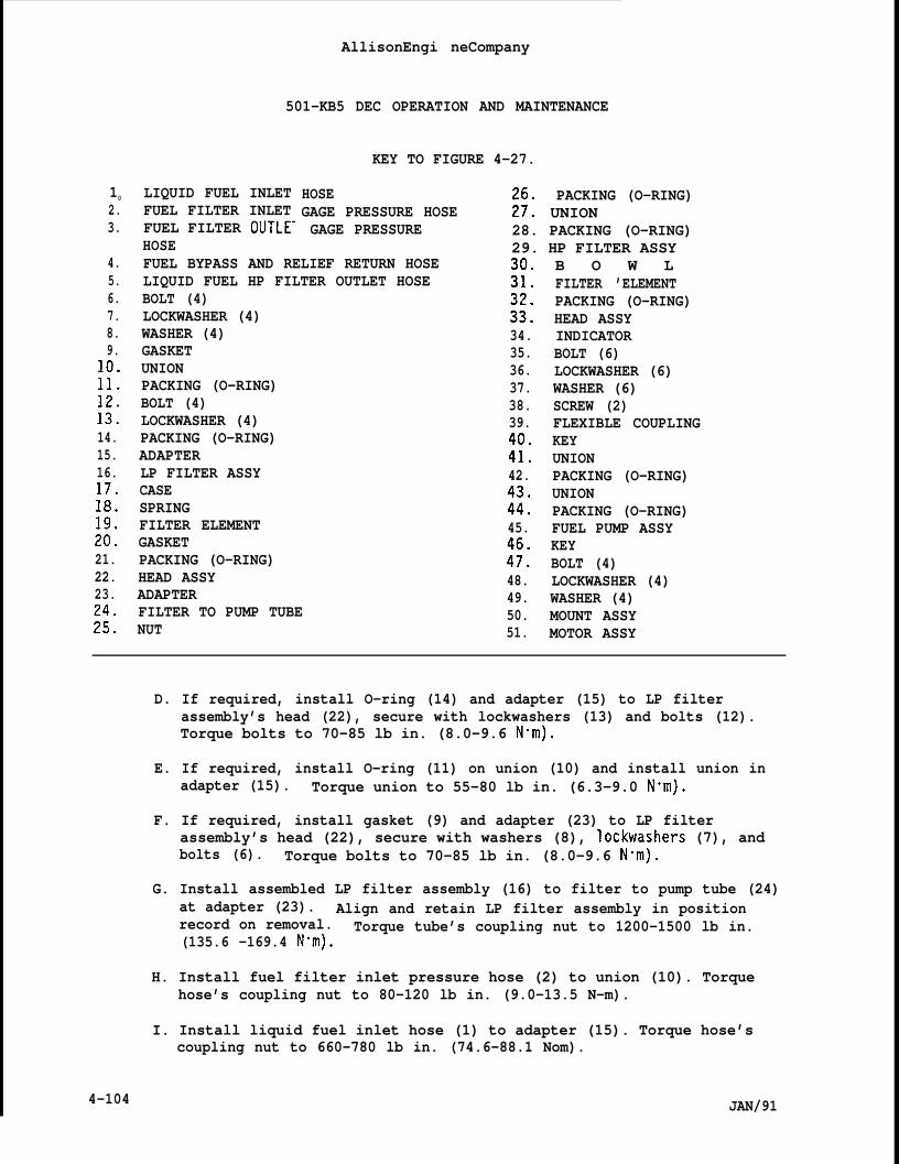
10 LIQUID FUEL INLET2. FUEL FILTER INLET3. FUEL FILTER OUTLE-
HOSE
AllisonEngi neCompany
501-KB5 DEC OPERATION AND MAINTENANCE
KEY TO FIGURE 4-27.
HOSE PACKING (O-RING)GAGE PRESSURE HOSE i;: UNIONGAGE PRESSURE 28. PACKING (O-RING)
29. HP FILTER ASSY4.5.6.7.8.9.
:!:
i::14.15.16.
&
:::21.22.23.
&
FUEL BYPASS AND RELIEF RETURN HOSELIQUID FUEL HP FILTER OUTLET HOSEBOLT (4)LOCKWASHER (4)WASHER (4)GASKETUNIONPACKING (O-RING)BOLT (4)LOCKWASHER (4)PACKING (O-RING)ADAPTERLP FILTER ASSYCASESPRINGFILTER ELEMENTGASKETPACKING (O-RING)HEAD ASSYADAPTERFILTER TO PUMP TUBENUT
:;:
:$34.35.36.37.38.39.
:;:42.
:::45.
:!:48.49.50.51.
B O W LFILTER ’ELEMENTPACKING (O-RING)HEAD ASSYINDICATORBOLT (6)LOCKWASHER (6)WASHER (6)SCREW (2)FLEXIBLE COUPLINGKEYUNIONPACKING (O-RING)UNIONPACKING (O-RING)FUEL PUMP ASSYKEYBOLT (4)LOCKWASHER (4)WASHER (4)MOUNT ASSYMOTOR ASSY
D. If required, install O-ring (14) and adapter (15) to LP filterassembly’s head (22), secure with lockwashers (13) and bolts (12).Torque bolts to 70-85 lb in. (8.0-9.6 Nom).
E. If required, install O-ring (11) on union (10) and install union inadapter (15). Torque union to 55-80 lb in. (6.3-9.0 N”m).
F. If required, install gasket (9) and adapter (23) to LP filterassembly’s head (22), secure with washers (8), lockwashers (7), andbolts (6). Torque bolts to 70-85 lb in. (8.0-9.6 N“m).
G. Install assembled LP filter assembly (16) to filter to pump tube (24)at adapter (23). Align and retain LP filter assembly in positionrecord on removal. Torque tube’s coupling nut to 1200-1500 lb in.(135.6 -169.4 Nom).
H. Install fuel filter inlet pressure hose (2) to union (10). Torquehose’s coupling nut to 80-120 lb in. (9.0-13.5 N-m).
I. Install liquid fuel inlet hose (1) to adapter (15). Torque hose’scoupling nut to 660-780 lb in. (74.6-88.1 Nom).
4-104 JAN/91
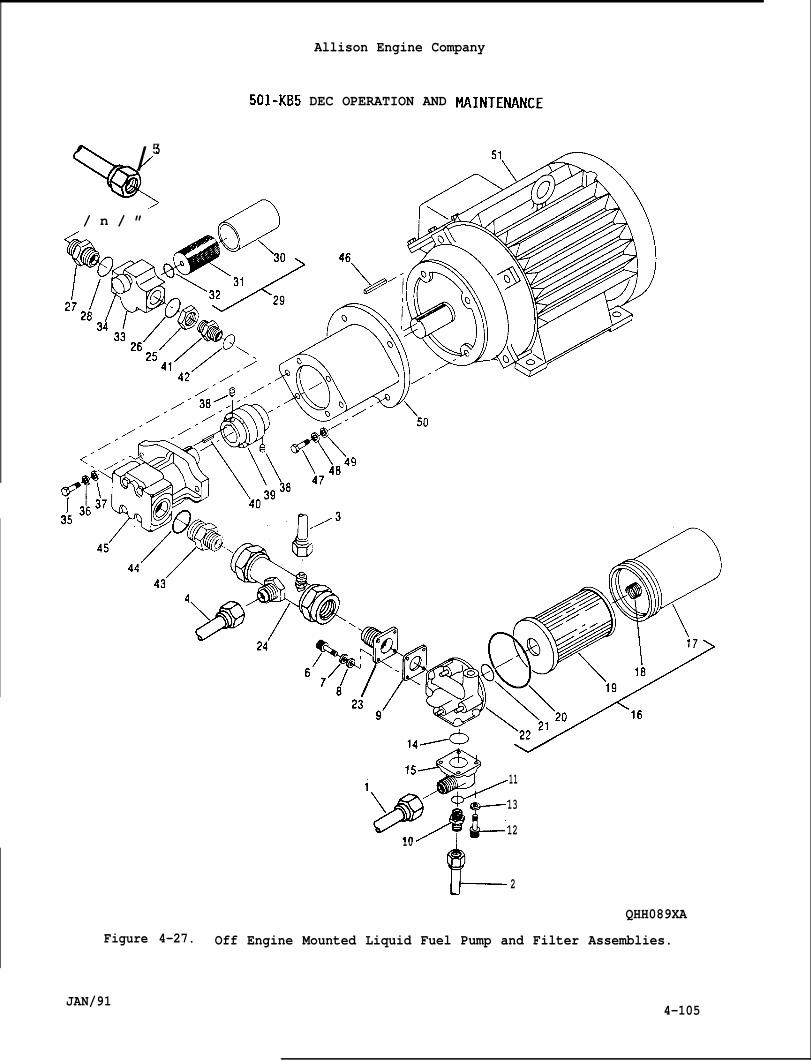
%
/5
/ n / ”
Allison Engine Company
501-KB5 DEC OPERATION AND
9“+ 11
1,>>$13
L
1210
2
QHH089XA
Figure 4-27. Off Engine Mounted Liquid Fuel Pump and Filter Assemblies.
JAN/914-105
Allison Engine Company
501-KB5 DEC OPERATION AND MAINTENANCE
4-150.
4-151.
4-152.
4-153.
4-154.
HIGH PRESSURE (HP) FUEL FILTER ASSEMBLY .
Descri~tion and O~eration.
A. The HP fuel filter assembly is located in liquid fuel system betweenthe off engine mounted fuel pump and fuel metering valve of the RAFT.
B. The HP fuel filter assembly has a cleanable wire mesh filter elementwith filtration rating of 40 microns absolute.
C. The HP fuel filter assembly has no bypass and if the filter elementbecame clogged the engine will not operate on liquid fuel. Amechanical indicator (34, Figure 4-27), located on the HP fuel filterassembly’s head, will indicate the filter element is becoming cloggedif the differential pressure drop is more than 45 psid (310.5 kPag).Normal clean differential pressure drop is not more than 7 psid (48.3kPad).
Filter Element Removal.
A. Remove bowl (30, Figure 4-27), filter element (31), and O-ring (32)from head assembly (33). Discard O-ring.
B. Inspect bowl (30) and filter element (31) for contamination.
Cleaning.
A. Clean filter element (31, Figure 4-27) and bowl (30) with cleaningsolvent, P-D-680-2.
B. Allow filter element (31) and bowl (30) to air dry. Inspect both fordamage.
Filter Element Installation.
A.
B.
c.
Install O-ring (32, Figure 4-27), filter element (31), and bowl (30)to head assembly (33).
Torque bowl (30) to 180-240 lb in. (20.3-27.1 Nom) and lockwirebowl to head assembly.
Perform operation and leakage test.
4-155. Removal.
A. Remove liquid fuel HP filter outlet hose (5, Figure 4-27) from union(27) .
4-106 JAN/91
I
4-156.
4-157.
4-158.
4-159.
JAN/91
Allison Engine Company
501-KB5 DEC OPERATION AND MAINTENANCE
NOTE
Record position of HP filter assembly for installation.
B. Loosen nut (25) and remove HP filter assembly (29) from union (41).Remove and discard O-ring (26).
C. If required, remove union (27) and O-ring (28) from HP filterassembly. Discard O-ring.
Installation.
A.
B.
c.
D.
E.
Install O-ring (28, Figure 4-27) on union (27) and install union inHP filter assembly (29) outlet. Torque union to 200-300 lb in.(22.6 -33.8 Nom).
If required, install nut (25) and O-ring (26) on union (41).
Install HP filter assembly (29) on union (41) to position recorded onremoval. Tighten nut (25).
Install liquid fuel HP filter outlet hose (5) to union (27). Torquehose’s coupling nut to 200-300 lb in. (22.6-33.8 N”m).
Perform operation and leakage test.
LIQUID FUEL PUMP.
Descri~tion and ODeration.
A.
B.
The electric motor driven liquid fuel pump is the main fuel pump forthe liquid fuel system.
The minimum flow rate is 12 gpm (45.4 Lpm) at 500 psig (3450 kPag)and 80”F (26.7”C) fuel inlet temperature at 1800 rpm electric motorspeed.
Removal.
A. Remove LP filter assembly (16, Figure 4-27) and filter to pump tube(24) per Paragraph 4-148.
B. Remove HP filter assembly (29) per Paragraph 4-155.
C. On fuel pump side, loosen screw (38) through bottom slot on mountassembly (50).
D. Remove bolts (35), lockwashers (36), washers (37), and assembled fuelpump assembly (45).
. 4-107
Allison Engine Company
501-KB5 DEC OPERATION AND MAINTENANCE
E. If required, remove union (41) and O-ring (42) from fuel pumpassembly (45). Discard O-ring.
F. If required, remove union (43) and O-ring (44) from fuel pumpassembly (45), Discard O-ring.
G. If required, remove bolts (47), lockwashers (48), washers (49), andmount assembly (50) from motor assembly (51).
H. If required, loosen screw (38) on motor side and remove flexiblecoupling (39).
I. If required, remove keys (40 and 46) from motor assembly and pumpassembly.
4-160. Installation.
A.
B.
c.
D.
E.
F.
G.
H.
I.
J.
4-108
If required, install key (46, Figure 4-27) and flexible coupling (39)on motor assembly (51). Torque screw (38) on motor side to 75-90 lbin. (8.5 -10.1 N“m).
Install mount assembly (50) on motor assembly (51) and secure withwashers (49), lockwashers (48), and bolts (47). Torque bolts to400-470 lb in. (45.2-53.1 Nom).
If required, install O-ring (44) on union (43) and install union onfuel pump assembly (45). Torque union to 780-1020 lb in. (88.2-115.2N“m),
If required, install O-ring (42) on union (41) and install union onfuel pump assembly (45). Torque union to 420-600 lb in. (47.5-67.7Nom).
If required, install key (40) in fuel pump assembly (45) drive shaftslot.
Install assembled fuel pump assembly (45) aligning flexible coupling(39) with key (46) and secure with washers (37), lockwashers (36),and” bolts (35). Torque bolts to 400-700 lb in. (45.2-53.1 N-m).
Through the bottom slot on the mount assembly, on the fuel pump side,torque screw (38)key (40) is align
Install HP filter
Install LP filterParagraph 4-149.
Perform operation
to 75-90 lb in. (8.5-10.1 N-m), making sure thein fuel pump assembly’s drive shaft slot.
assembly (29) per Paragraph 4-156.
assembly (16) and filter to pump tube (24) per
and leakage test.
JAN/91
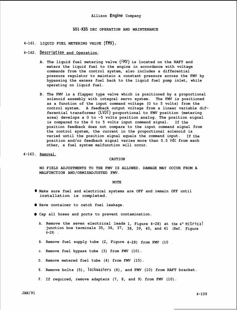
4-161.
4-162.
4-163.
●
●
●
JAN/91
Allison Engine Company
501-KB5 DEC OPERATION AND MAINTENANCE
LIQUID FUEL METERING VALVE (FMV).
Descrir)tion and Operation.
A. The liquid fuel metering valve (FMV) is located on the RAFT andmeters the liquid fuel to the engine in accordance with voltagecommands from the control system, also includes a differentialpressure regulator to maintain a constant pressure across the FMV bybypassing the excess fuel back to the liquid fuel pump inlet, whileoperating on liquid fuel.
B. The FMV is a flapper type valve which is positioned by a proportionalsolenoid assembly with integral servo system. The FMV is positionedas a function of the input command voltage (O to 5 volts) from thecontrol system. A feedback output voltage from a linear variable dif-ferential transformer (LVDT) proportional to FMV position (meteringarea) develops a O to -5 volts position analog. The position signalis compared to the O to 5 volts input command signal. If theposition feedback does not compare to the input command signal fromthe control system, the current in the proportional solenoid isvaried until the position signal equals the command input. If theposition and/or feedback signal varies more than 0.5 vdc from eachother, a fuel system malfunction will occur.
Removal.CAUTION
NO FIELD ADJUSTMENTS TO THE FMV IS ALLOWED. DAMAGE MAY OCCUR FROM AMALFUNCTION AND/ORMISADJUSTED FMV.
NOTE
Make sure fuel and electrical systems are OFF and remain OFF untilinstallation is completed. -
Have container to catch fuel leakage.
Cap all hoses and ports to prevent contamination.
A.
B.
c.
D.
E.
F.
Remove the seven electrical leadsjunction box terminals 35, 36, 37,4-29) .
Remove fuel supply tube (2, Figure
1, Figure 4-28) at38, 39, 40, and 41
4-28) from FMV (10
the e“(Ref.
.
ectricalFigure
Remove fuel bypass tube (3) from FMV (10).
Remove metered fuel tube (4) from FMV (10).
Remove bolts (5), lockwashers (6), and FMV (10) from RAFT bracket.
If required, remove adapters (7, 8, and 9) from FMV (10).
4-109
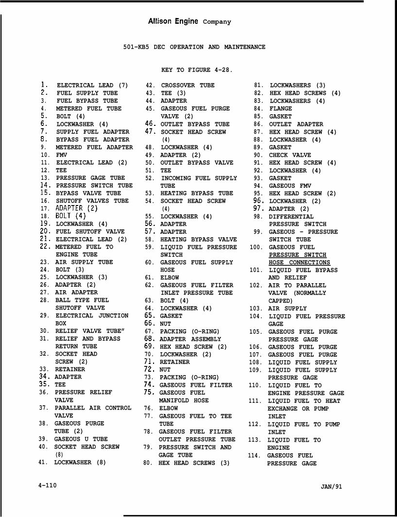
i3.4.
::
;:9.10.11.12.13.
k16.17.18.
;::
&
23.24.25.26.27.28.
29.
30.31.
32.
33.
%36.
37.
38.
39.40.
41.
ELECTRICAL LEAD (7)FUEL SUPPLY TUBEFUEL BYPASS TUBEMETERED FUEL TUBEBOLT (4)LOCKWASHER (4)SUPPLY FUEL ADAPTERBYPASS FUEL ADAPTERMETERED FUEL ADAPTERFMVELECTRICAL LEAD (2)TEEPRESSURE GAGE TUBEPRESSURE SWITCH TUBEBYPASS VALVE TUBESHUTOFF VALVES TUBE104~T7~)(2)
LOCKWASHER (4)FUEL SHUTOFF VALVEELECTRICAL LEAD (2)METERED FUEL TOENGINE TUBEAIR SUPPLY TUBEBOLT (3)LOCKWASHER (3)ADAPTER (2)AIR ADAPTERBALL TYPE FUELSHUTOFF VALVEELECTRICAL JUNCTIONBOXRELIEF VALVE TUBE”RELIEF AND BYPASSRETURN TUBESOCKET HEADSCREW (2)RETAINERADAPTERTEEPRESSURE RELIEFVALVEPARALLEL AIR CONTROLVALVEGASEOUS PURGETUBE (2)GASEOUS U TUBESOCKET HEAD SCREW(8)LOCKWASHER (8)
AHlson Engine Company
501-KB5 DEC OPERATION AND MAINTENANCE
KEY TO FIGURE 4-28.
42.43.44.45.
:!:
48.49.50.51.52.
53.54.
55.
:!:58.59.
60.
61.62.
63.64.
:;:67.
:::70.
;;:73.
;::
76.77.
78.
79.
80.
CROSSOVER TUBETEE (3)ADAPTERGASEOUS FUEL PURGEVALVE (2)OUTLET BYPASS TUBESOCKET HEAD SCREW(4)LOCKWASHER (4)ADAPTER (2)OUTLET BYPASS VALVETEEINCOMING FUEL SUPPLYTUBEHEATING BYPASS TUBESOCKET HEAD SCREW(4)LOCKWASHER (4)ADAPTERADAPTERHEATING BYPASS VALVELIQUID FUEL PRESSURESWITCHGASEOUS FUEL SUPPLYHOSEELBOWGASEOUS FUEL FILTERINLET PRESSURE TUBEBOLT (4)LOCKWASHER (4)GASKETNUTPACKING (O-RING)ADAPTER ASSEMBLYHEX HEAD SCREW (2)LOCKWASHER (2)RETAINERNUTPACKING (O-RING)GASEOUS FUEL FILTERGASEOUS FUELMANIFOLD HOSEELBOWGASEOUS FUEL TO TEETUBEGASEOUS FUEL FILTEROUTLET PRESSURE TUBEPRESSURE SWITCH ANDGAGE TUBEHEX HEAD SCREWS (3)
81.82.83.84.85.86.87.88.89.90.91.92.93.94.95.
;!:98.
99.
100.
101.
102.
103.104.
105.
106.107.108.109.
110.
111.
112.
113.
114.
LOCKWASHERS (3)HEX HEAD SCREWS (4)LOCKWASHERS (4)FLANGEGASKETOUTLET ADAPTERHEX HEAD SCREW (4)LOCKWASHER (4)GASKETCHECK VALVEHEX HEAD SCREW (4)LOCKWASHER (4)GASKETGASEOUS FMVHEX HEAD SCREW (2)LOCKWASHER (2)ADAPTER (2)DIFFERENTIALPRESSURE SWITCHGASEOUS - PRESSURESWITCH TUBEGASEOUS FUELPRESSURE SWITCHHOSE CONNECTIONSLIQUID FUEL BYPASSAND RELIEFAIR TO PARALLELVALVE (NORMALLYCAPPED)AIR SUPPLYLIQUID FUEL PRESSUREGAGEGASEOUS FUEL PURGEPRESSURE GAGEGASEOUS FUEL PURGEGASEOUS FUEL PURGELIQUID FUEL SUPPLYLIQUID FUEL SUPPLYPRESSURE GAGELIQUID FUEL TOENGINE PRESSURE GAGELIQUID FUEL TO HEATEXCHANGE OR PUMPINLETLIQUID FUEL TO PUMPINLETLIQUID FUEL TOENGINEGASEOUS FUELPRESSURE GAGE
JAN/914-110
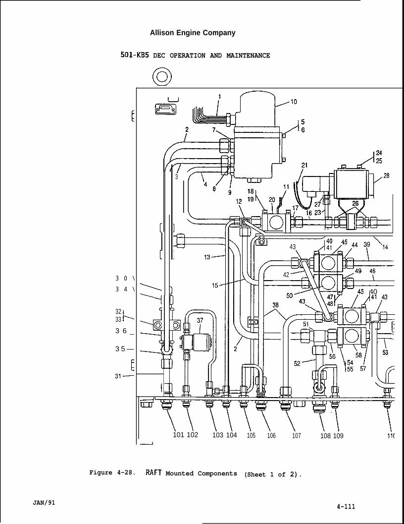
3 0 \
3 4 \
3233 1=
3 6 _
3 5 —
Allison Engine Company
DEC OPERATION AND MAINTENANCE
o
Figure 4-28.
JAN/91
1
‘& r015
&iiiFr’6 ,9,
[
[
I
“/ 6FGf’kl3
El===1 13-
15-
ICl+ r+
2
101 102 103 104
Mounted Components
N43
I
42
!5 40A 41 /43A/
—
F[,53
105 106 107 108 109 11[
(Sheet 1 of 2).
4-111
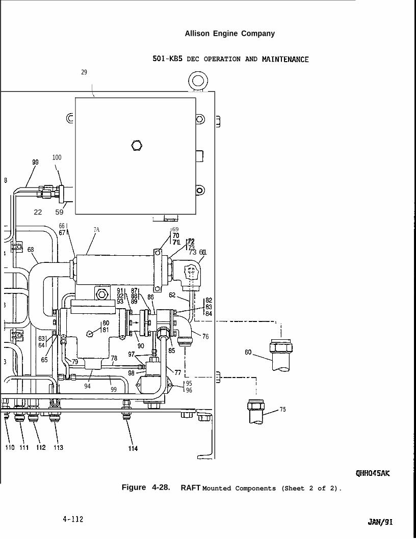
Allison Engine Company
501-KB5
29
DEC OPERATION AND
(CJ\
c
79100\
6—
I II
22 59
\ 66 I
c)’
\
Q
o
I7A 169
m ti
7071 72
73 61
C)rn‘I*1,
::m d4!lwh”? ‘2T—
6
,f *!-! i
1\
{ lb’+— -—.-
94 9599 96
I
“7Iil li2 li3 li4 CJ
.— -—-—-—- 1
i
60
.+?)4
3–-–--:I
f%
75
Figure 4-28. RAFT Mounted Components (Sheet 2 of 2).
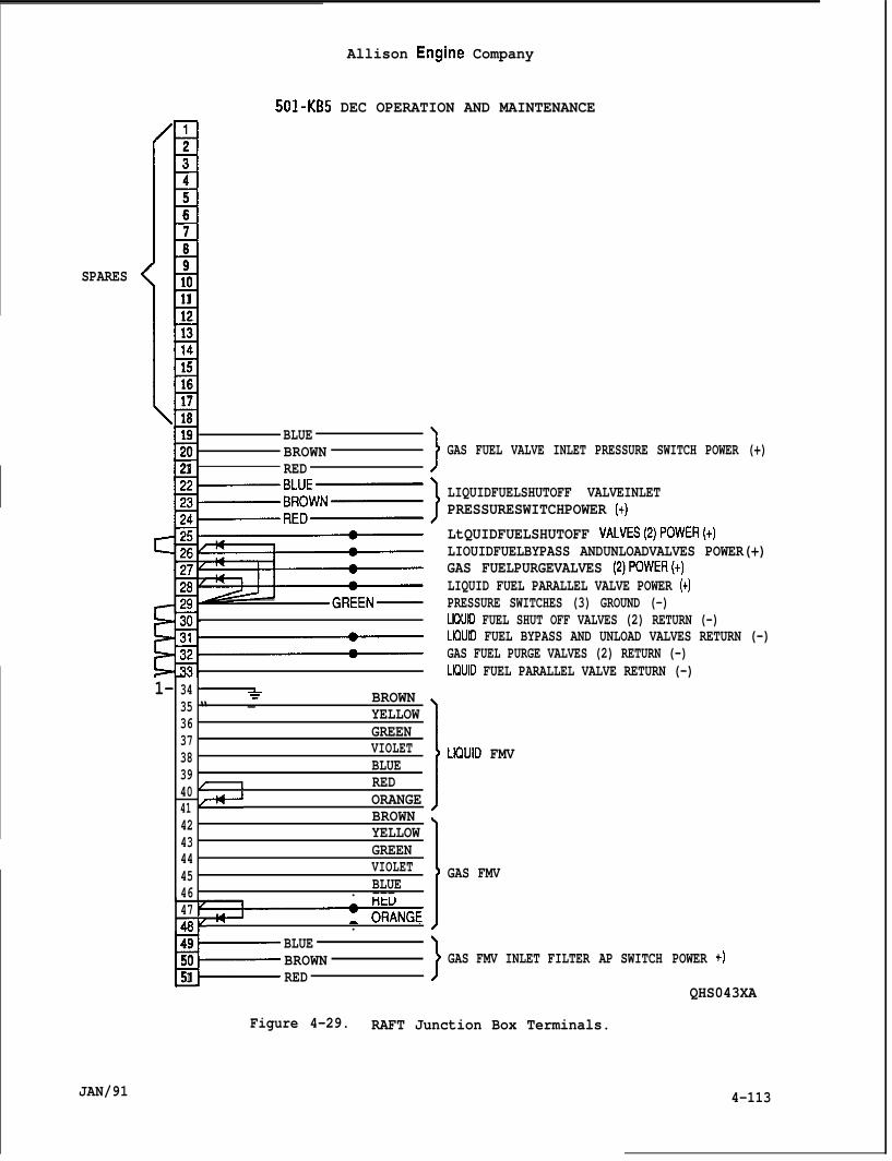
Allison Engine Company
501-KB5 DEC OPERATION AND MAINTENANCE
SPARES
JAN/91
:11234567891011121314
(~1516171819 BLUE20 BROWN21 RED
1--34“*
35 “ - BROWN
36 YELLOW
37 GREEN
38 VIOLET
39 BLUE
40 [ 1 RED
41 ~+ ORANGE
42 BROWN
43 YELLOW
44 GREEN
45 VIOLET
46 BLUE. ---4748V .
B-49 BLUE50 BROWN51 RED
}
}
11\
GAS FUEL VALVE INLET PRESSURE SWITCH POWER (+)
LIQUIDFUELSHUTOFF VALVEINLETPRESSURESWITCHPOWER (+)
LtQUIDFUELSHUTOFF VALVES(2)POWER(+)LIOUIDFUELBYPASS ANDUNLOADVALVES POWER(+)GAS FUELPURGEVALVES (2)POWER(+)LIQUID FUEL PARALLEL VALVE POWER (+)PRESSURE SWITCHES (3) GROUND (-)LKIUID FUEL SHUT OFF VALVES (2) RETURN (-)L~UID FUEL BYPASS AND UNLOAD VALVES RETURN (-)GAS FUEL PURGE VALVES (2) RETURN (-)LK)UID FUEL PARALLEL VALVE RETURN (-)
LK2UID FMV
GAS FMV
J GAS FMV INLET FILTER AP SWITCH POWER +)
QHS043XA
Figure 4-29. RAFT Junction Box Terminals.
4-113
Allison Engine Company
501-KB5 DEC OPERATION AND MAINTENANCE
4-164. Installation.
A.
B.
c.
D.
E.
F.
G.
H.
I.
J.
4-114
If required, install metered fuel adapter (9, Figure 4-28) on FMV(lo). Torque adapter to 300-450 lb in. (33.9-50.8 Nom).
If required, install bypass fuel adapter (8) on FMV (10). Torqueadapter to 200-300 lb in. (22.6-33.8 N-m).
If required, install supply fuel adapter (7) on FMV. Torque adapterto 420-600 lb in. (47.5-67.7 Nom).
Install assembled FMV (10) to RAFT bracket and secure withlockwashers (6) and bolts (5). Torque bolts to 120-150 lb in.(13.6 -16.9 N-m).
Install metered fuel tube (4) to metered fuel adapter (9). Retainadapter from moving(53.7 -64.9 N-m).
Install bypass fueladapter from moving(36.8 -45.1 N-m).
Install supply fueladapter from moving(74.6 -88.1 N$m).
and torque tube’s coupling nut to 475-575 lb in.
tube (3) to bypass fuel adapter (8). Retainand torque tube’s coupling nut .to 325-400 lb in.
tube (2) to supply fuel adapter (7), Retainand torque tube’s coupling nut to 660-780 lb in.
Connect seven electrical leads (1) to electrical junction boxterminals as follows (Ref. Figure 4-29):
1. Brown lead to terminal 35.
2. Yellow lead to terminal 36.
3. Green lead to terminal 37.
4. Violet lead to terminal 38.
5. Blue lead to terminal 39.
6. Red lead to terminal 40.
7. Orange lead to terminal 41.
Using 5/16 (0.3125) inch Allen wrench loosen bleed plug and motorengine to bleed air from fuel system. Tighten bleed plug.
Perform operation and leakage test,
JAN/91
4-165.
4-166.
4-167.
●
●
●
JAN/91
Allison Engine Company
501 -KB5 DEC OPERATION AND MAINTENANCE
LIQUID FUEL SHUTOFF VALVE.
Descrir)tion and Ot)eration.
A. The fuel shutoff valve is located between the FMV and ball type fuelshutoff valve on the RAFT.
B. The fuel shutoff valve is a normally closed electrical solenoidoperated valve.
C. The fuel shutoff valve electrical power is controlled by the controlsystem. During the starting cycle, at 2200 engine rpm, electricalpower from the control system is sent to open the fuel shutoffvalve. The fuel shutoff valve will close whenever electrical poweris removed by the shutdown circuits of the control system.
D. The purpose of the fuel s!ball type fuel shutoff va-means of a quick shutdownmetered fuel flow.
Removal.
utoff is to control the metered fuel to theve. The fuelof the engine
shutoff valve provides theoperation by stopping the
NOTE
Cap all openings to prevent contamination.
Have a container to catch fuel leakage.
Make sure fuel and electrical systems are OFF and remain OFF untilinstallation is completed.
A. Remove the two electrical leads (11, Figure 4-28) at the electricaljunction box terminals 25 and 30 (Ref. Figure 4-29).
B. Remove metered fuel tube (4, Figure 4-28) at tee (12).
C. Remove pressure gage tube (13) at tee (12).
D. Remove pressure switch tube (14) at tee (12).
E. Remove bypass valve tube (15) at tee (12).
F. Remove shutoff valves tube (16) from fuel shutoff valve adapter (17).
G. Remove bolts (18), lockwashers (19), and assembled fuel shutoff valve(20) from RAFT bracket.
4-115
Allison Engine Company
501-KB5 DEC OPERATION AND MAINTENANCE
NOTE
Record position of tee for installation.
H. If required, remove adapters (17) and tee (12) from fuel shutoffvalve (20).
4-168. Installation.
A.
B.
c.
D.
E.
F.
G.
H.
I.
J.
Install adapters (17, Figure 4-28) in fuel shutoff valve (20) on eachend. Torque adapter to 200-300 lb in. (22.6-33.8 N“m).
Install tee (12) on fuel shutoff valve inlet side to positionrecorded on removal.
Install assembled fuel shutoff valve (20) to RAFT bracket and securewith lockwashers (19) and bolts (18). Torque bolts to 60-65 lb in.(6.8-7.3 Nom).
Install shutoff valves tube (16) to fuel shutoff valve outlet adapter(17)0 Retain adapter from turning and torque tube’s coupling nut to325-400 lb in. (36.8-45.1 N*m).
Install bypass valve tube (15) to tee (12). Retain tee from turningand torque tube’s coupling nut to 325-400 lb in. (36.8-45.1 N’m).
Install pressure switch tube (14) to tee (12). Retain tee fromturning and torque tube’s coupling nut to 35-40 lb in. (4.0-4.5N“m).
Install pressure gage tube (13) to tee (12). Retain tee from turningand torque tube’s coupling nut to 35-40 lb in. (4.0-4.5 Nom).
Install metered fuel tube (4) to tee (12). Retain tee from turningand torque tube’s coupling nut to 325-400 lb in. (36.8-45.1 N“m).
Connect the two electrical leads (11) to electrical junction boxterminals as follows (Ref. Figure 4-29):
1. Power (+) to terminal 25.2. Return (-) to terminal 30.
Perform operation and leakage test.
4-169. LIQUID FUEL SHUTOFF VALVE (BALL TYPE).
4-170. Descri~tion and O~eration.
A. The ball type fuel shutoff valve is located between the quick actingfuel shutoff valve and the liquid fuel to engine outlet on the RAFT.
4-116 JAN/91
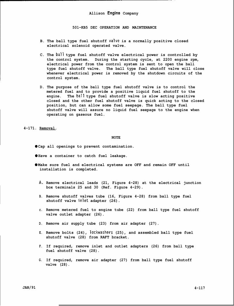
Allison Engine Company
501-KB5 DEC OPERATION AND MAINTENANCE
B. The ball type fuel shutoff valve is a normally positive closedelectrical solenoid operated valve.
C. The ball type fuel shutoff valve electrical power is controlled bythe control system. During the starting cycle, at 2200 engine rpm,electrical power from the control system is sent to open the balltype fuel shutoff valve. The ball type fuel shutoff valve will closewhenever electrical power is removed by the shutdown circuits of thecontrol system.
D. The purpose of the ball type fuel shutoff valve is to control themetered fuel and to provide a positive liquid fuel shutoff to theengine. The ball type fuel shutoff valve is slow acting positiveclosed and the other fuel shutoff valve is quick acting to the closedposition, but can allow some fuel seepage. The ball type fuelshutoff valve will assure no liquid fuel seepage to the engine whenoperating on gaseous fuel.
4-171. Removal.
NOTE
● Cap all openings to prevent contamination.
● Have a container to catch fuel leakage.
● Make sure fuel and electrical systems are OFF and remain OFF untilinstallation is completed.
A.
B.
c.
D.
E.
F.
G.
JAN/91
Remove electrical leads (21, Figure 4-28) at the electrical junctionbox terminals 25 and 30 (Ref. Figure 4-29).
Remove shutoff valves tube (16, Figure 4-28) from ball type fuelshutoff valve inlet adapter (26).
Remove metered fuel to engine tube (22) from ball type fuel shutoffvalve outlet adapter (26).
Remove air supply tube (23) from air adapter (27).
Remove bolts (24), lockwashers (25), and assembled ball type fuelshutoff valve (28) from RAFT bracket.
If required, remove inlet and outlet adapters (26) from ball typefuel shutoff valve (28).
If required, remove air adapter (27) from ball type fuel shutoffvalve (28).
4-117
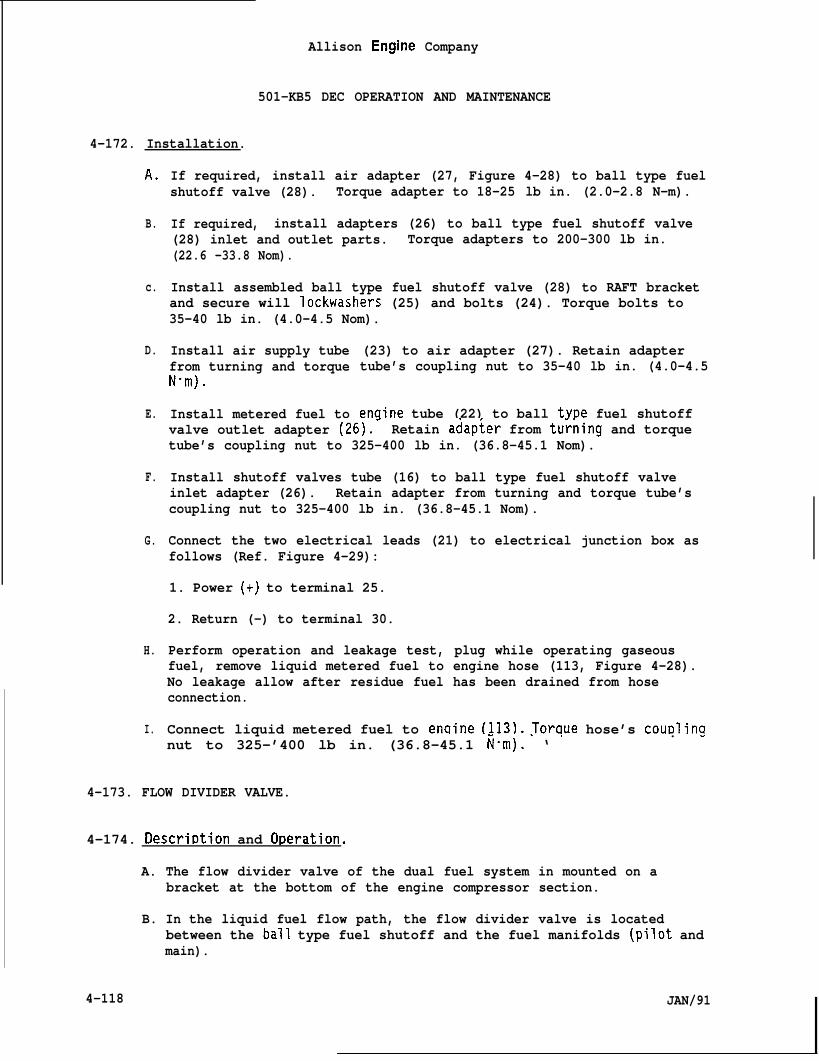
Allison Engine Company
501-KB5 DEC OPERATION AND MAINTENANCE
4-172. Installation.
A.
B.
c.
D.
E.
F.
G.
H.
I.
If required, install air adapter (27, Figure 4-28) to ball type fuelshutoff valve (28). Torque adapter to 18-25 lb in. (2.0-2.8 N-m).
If required, install adapters (26) to ball type fuel shutoff valve(28) inlet and outlet parts. Torque adapters to 200-300 lb in.(22.6 -33.8 Nom).
Install assembled ball type fuel shutoff valve (28) to RAFT bracketand secure will Iockwashers (25) and bolts (24). Torque bolts to35-40 lb in. (4.0-4.5 Nom).
Install air supply tubefrom turning and torqueN“m).
Install metered fuel to
(23) to air adapter (27). Retain adaptertube’s coupling nut to 35-40 lb in. (4.0-4.5
enqine tube (22) to ball twe fuel shutoffvalve outlet adapter (26).- Retain adap~er from tu~ning and torquetube’s coupling nut to 325-400 lb in. (36.8-45.1 Nom).
Install shutoff valves tube (16) to ball type fuel shutoff valveinlet adapter (26). Retain adapter from turning and torque tube’scoupling nut to 325-400 lb in. (36.8-45.1 Nom).
Connect the two electrical leads (21) to electrical junction box asfollows (Ref. Figure 4-29):
1. Power (+) to terminal 25.
2. Return (-) to terminal 30.
Perform operation and leakage test, plug while operating gaseousfuel, remove liquid metered fuel to engine hose (113, Figure 4-28).No leakage allow after residue fuel has been drained from hoseconnection.
Connect liquid metered fuel to enqine (113). Toraue hose’s cou~linqnut to 325-’400 lb in. (36.8-45.1 ~-m).’ ‘ ‘
. -
4-173. FLOW DIVIDER VALVE.
4-174. Descrir)tion and Or)eration.
A. The flow divider valve of the dual fuel system in mounted on abracket at the bottom of the engine compressor section.
B. In the liquid fuel flow path, the flow divider valve is locatedbetween the ball type fuel shutoff and the fuel manifolds (pilot andmain).
4-118 JAN/91
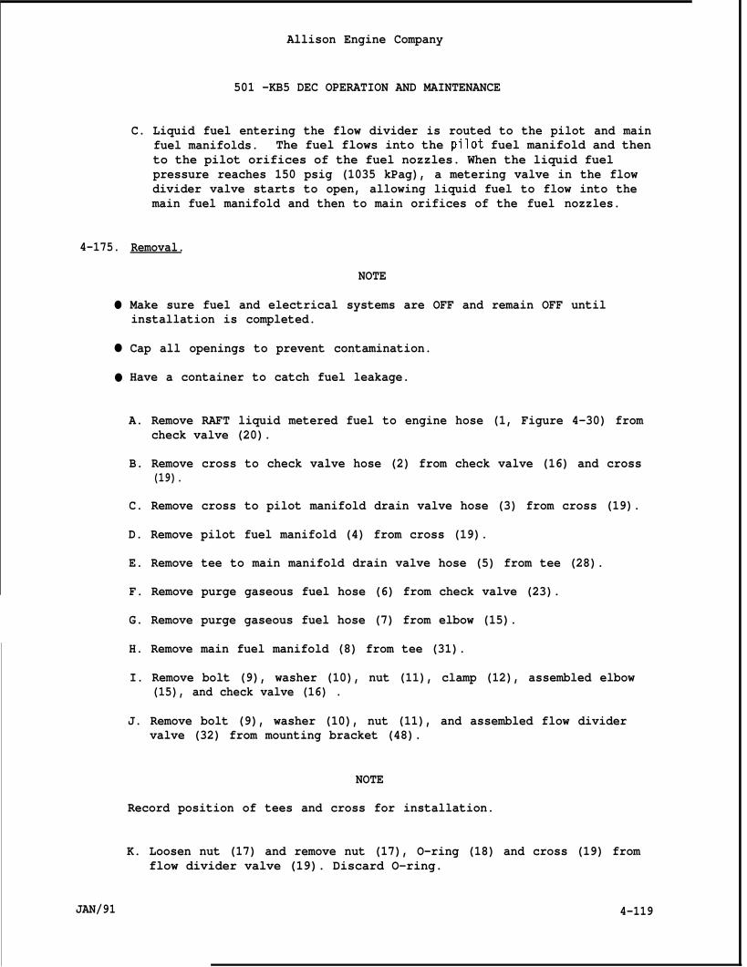
4-175.
●
●
●
JAN/91
Allison Engine Company
501 -KB5 DEC OPERATION AND MAINTENANCE
C. Liquid fuel entering the flow divider is routed to the pilot and mainfuel manifolds. The fuel flows into the pilot fuel manifold and thento the pilot orifices of the fuel nozzles. When the liquid fuelpressure reaches 150 psig (1035 kPag), a metering valve in the flowdivider valve starts to open, allowing liquid fuel to flow into themain fuel manifold and then to main orifices of the fuel nozzles.
Removal.
NOTE
Make sure fuel and electrical systems are OFF and remain OFF untilinstallation is completed.
Cap all openings to prevent contamination.
Have a container to catch fuel leakage.
A. Remove RAFT liquid metered fuel to engine hose (1, Figure 4-30) fromcheck valve (20).
B. Remove cross to check valve hose (2) from check valve (16) and cross(19).
C. Remove cross to pilot manifold drain valve hose (3) from cross (19).
D. Remove pilot fuel manifold (4) from cross (19).
E. Remove tee to main manifold drain valve hose (5) from tee (28).
F. Remove purge gaseous fuel hose (6) from check valve (23).
G. Remove purge gaseous fuel hose (7) from elbow (15).
H. Remove main fuel manifold (8) from tee (31).
I. Remove bolt (9), washer (10), nut (11), clamp (12), assembled elbow(15), and check valve (16) .
J. Remove bolt (9), washer (10), nut (11), and assembled flow dividervalve (32) from mounting bracket (48).
NOTE
Record position of tees and cross for installation.
K. Loosen nut (17) and remove nut (17), O-ring (18) and cross (19) fromflow divider valve (19). Discard O-ring.
4-119
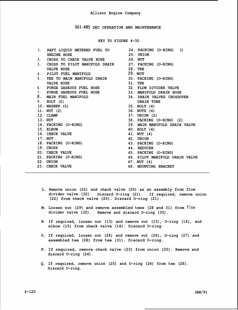
Allison Engine Company
501-KB5 DEC OPERATION AND MAINTENANCE
KEY TO FIGURE 4-30.
1. RAFT LIQUID METERED FUEL TOENGINE HOSE
2. CROSS TO CHECK VALVE HOSE3. CROSS TO PILOT MANIFOLD DRAIN
VALVE HOSE4. PILOT FUEL MANIFOLD5. TEE TO MAIN MANIFOLD DRAIN
VALVE HOSE6. PURGE GASEOUS FUEL HOSE7. PURGE GASEOUS FUEL HOSE8. MAIN FUEL MANIFOLD9. BOLT (2)10. WASHER (2)11. NUT (2)12. CLAMP13. NUT14. PACKING (O-RING)15. ELBOW16. CHECK VALVE17. NUT18. PACKING (O-RING)19. CROSS20. CHECK VALVE21. PACKING (O-RING)22. UNION23. CHECK VALVE
24. PACKING (O-RING)25. UNION26. NUT27. PACKING (O-RING)28. TEE29, NUT30. PACKING (O-RING)31. TEE
2)
32. FLOW DIVIDER VALVE33. MANIFOLD DRAIN HOSE34. DRAIN VALVES CROSSOVER
DRAIN TUBE35. BOLT (4)36. NUTS (4)37. UNION (2)38. PACKING (O-RING) (2)39. MAIN MANIFOLD DRAIN VALVE40. BOLT (4)41. NUT (4)42. UNION43. PACKING (O-RING)44. REDUCER45. PACKING (O-RING)46. PILOT MANIFOLD DRAIN VALVE47. NUT (4)48. MOUNTING BRACKET
L. Remove union (22) and check valve (20) as an assembly from flowdivider valve (32). Discard O-ring (21). If required, remove union(22) from check valve (20). Discard O-ring (21).
M. Loosen nut (29) and remove assembled tees (28 and 31) from flowdivider valve (32). Remove and discard O-ring (30).
N. If required, loosen nut (13) and remove nut (13), O-ring (14), andelbow (15) from check valve (16). Discard O-ring.
O. If required, loosen nut (26) and remove nut (26), O-ring (27) andassembled tee (28) from tee (31). Discard O-ring.
P. If required, remove check valve (23) from union (25). Remove anddiscard O-ring (24).
Q. If required, remove union (25) and O-ring (24) from tee (28).Discard O-ring.
4-120 JAN/91
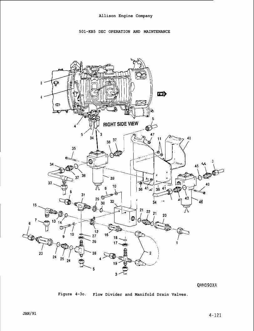
Allison Engine Company
I’i
501-KB5 DEC OPERATION AND MAINTENANCE
8111111/1 )
4
8
45 44 3
‘;-=“-*=I “c 4 0
**7 , F4?T!3 b,
t).
Figure 4-3o. Flow Divider and Manifold Drain Valves.
JAN/91
Allison Engine Company
501-KB5 DEC OPERATION AND MAINTENANCE
4-176. Installation.NOTE
A.
B.
c.
D.
E.
F.
G.
H.
I.
J.
K.
L.
4-122
Met O-rings with clean eng ne oil.
If required, install O-ring (24, Figure 4-30) on union (25) andinstall union in tee (28). Torque union to 200-300 lb in. (22.6-33.8Nom).
If required, install O-ring (24) on union (25) and install checkvalve (23) on union. Retain union from turning and torque checkvalve to 200-300 lb in. (22.6-33.8 N“m).
If required, install nut (26) and O-ring (27) on assembled tee (28).Install assembled tee in tee (31). Do not tighten nut (26) now.
If required, install O-ring (21) on union (22) and install union withO-ring in check valve (20). Torque union to 200-300 lb in.(22.6 -33.8 Nom).
If required, install nut (13) and O-ring (14) on elbow (15) andinstall elbow in check valve (16) and clamp (12) on check valve.Tighten nut (13) now.
Install nut (29) and O-ring (30) on assembled tee (31). Installassembled tee in flow divider valve (32) main manifold outlet, toposition record on removal.
Install O-ring (21) on union (22) and install assembled union andcheck valve (20) in inlet Dort of flow divider valve (32). Toraueunion to 200~300 lb in. (22.6-33.8 N-m).
Install nut (17) and O-ring (18) on cross (19) andcross in flow divider valve (32) pilot manifold ou-record on removal. Do not tighten nut (17) now.
Install assembled flow divider valve [32) to mount
. ,
install assembledlet, to position
ng bracket (48),with assembledsecure with bolts (9), washers (10), ~nd’nuts (11)
check valve (16) clamp (12) installed on rear bolt. Torque nuts to74-89 lb in. (8.4-10.0 Nom).
Install main fuel manifold (8) to tee (31). Retain tee from turningand torque hose’s coupling nut to 80-120 lb in. (9.0-13.5 N-m).Tighten nut (13) now.
Install purge gaseous fuel hose (7) to elbow (15). Retain elbow fromturning and torque hose’s coupling nut to 80-120 lb in. (9.0-13.5N“m). Tighten nut (13) now.
Install purge gaseous fuel hose (6) to check valve (23). Retaincheck valve from turning .and torque hose’s coupling nut to 325-400 lbin. (36.8 -45.1 Nom).
JAN/91
Allison Engine Company
501-KB5 DEC OPERATION AND MAINTENANCE
4-177.
4-178.
M,
o.
P.
Q.
R.
s.
T.
Install tee to main manifold drain valve hose (5) to tee (28).Retain tee from turning and tor-que hose’s coupling nut to 325-400 lbin. (36.8 -45.1 Nom). Tighten nuts (26 and 29) now.
Install pilot fuel manifold (4) to cross (19). Retain cross fromturning and torque pilot fuel manifold coupling nut to 80-120 lb in.(9.0 -13.5 N“m).
Install cross to pilot manifold drain valve hose (3) to cross (19).Retain cross from turning and torque hose’s coupling nut to 80-120 lbin. (9.0 -13.5 Nom).
Install cross to check valve hose (2) to check valve (16). Retaincheck valve from turning and torque hose’s coupling nut to 80-120 lbin. (9.0 -13.5 Nom).
Install cross to check valve hose (2) to cross (19). Retain crossfrom turning and torque hose’s coupling nut to 80-120 lb in.(9.0 -13.5 Nom). Tighten nut (17) now.
Install liquid metered fuel RAFT to engine hose (1) to check valve(20) . Retain check valve from turning and torque hose’s coupling nutto 325-400 lb in. (36.8-45.1 Nom).
Perform an operation and leakage test.
MANIFOLD DRAIN VALVES (PILOT AND MAIN).
Description and Ot)eration.
A.
B.
c
The liquid fuel system has two manifold drain valves (a main and apilot), one for each fuel manifold. They are mounted on a bracketnear the bottom of the compressor section. Their purpose is to drainany liquid fuel remaining in the fuel nozzles or manifolds when theengine is shutdown. The manifold drain valves are energized opensimultaneously with the closing of the fuel shutoff valve.
The pilot manifold drain valve inlet tees into the pilot fuelmanifold. The main manifold drain valve tees into the main fuelmanifold. Both manifold drain valve outlets are connected to acrossover drain tube which has a single outlet fitting. The draintube outlet should be connected to a drain collector tank. Themanifold drain valves are spring-loaded to the closed position andelectrical solenoid actuated to open by command of the controlsystem.
The control system opens the manifold drain valves immediately uponany shutdown signal. Combustion section pressure then forces fuelremaining in the fuel nozzles and manifolds to the drain tank throughthe manifold drain valves. During starts, the manifold drain valvesare held open until 2200 engine rpm. After shutdown, the manifold
JAN/91 4-123
4-179.
●
●
●
4-180.
4-124
Allison Engine Company
501-KB5 DEC OPERATION AND MAINTENANCE
drain valves are held open by a timer for 30 seconds.
CAUTION
THE FLUID IN THE DRAIN TANK(S) MUST NOT CREATE A HEAD PRESSURE CAUSINGA BACK PRESSURE ON THE DRAIN SYSTEM. DAMAGE MAY OCCUR.
D. It is essential that the fuel manifold drains have little or no backpressure. For this reason, the drain line must not have kinks orother restrictions.
Main Manifold Drain Valve Removal.
NOTE
Make sure fuel and electrical systems are OFF and remain OFF untilInstallation is completed.
Cap all openings to prevent contamination.
Have a container to catch fuel leakage.
A,
B.
c.
D.
E.
F.
Disconnect electrical connections of the main manifold drain valve(39, Figure 4-30).
Remove tee to main manifold drain valve hose (5) from main manifolddrain valve (39).
Remove manifold drain hose (33) from drain valves crossover draintube (34).
Remove draiti valves crossover drain tube (34) from main manifolddrain valve (39) and pilot manifold drain valve (46) outlet ports.
Remove bolts (35), nuts (36), and assembled main manifold drain va’(39) from mounting bracket (48) .
ve
If required, remove unions (37) and O-rings (38) from main manifolddrain valve (39). Discard O-rings. - - -
Main Manifold Drain Valve Installation.
NOTE
Wet O-rings with clean engine oil.
A. If required, install an O-ring (38, Figure 4-30) and each union (37)and the O-ring side into main manifold drain valve (39). Torque eachunion to 200-300 lb in. (22.6-33.8 N-m).
JAN/91
Allkon Engine Company
501-KB5 DEC OPERATION AND MAINTENANCE
4-181.
●
●
●
JAN/91
B.
c.
D.
E.
F.
G.
Install assembled main manifold drain valve (39) to mounting bracket(48) with outlet port to the right, to connect with the drain valvescrossover drain tube (34), and secure with bolts (35) and nuts (36).Torque nuts to 74-89 lb in. (8.4-10.0 N-m).
Install drain valves crossover tube (34) to the outlet ports of mainmanifold drain valve (39) and pilot manifold drain valve (46).Retain outlet union from turning and torque each tube’s coupling nutto 325-400 lb in. (36.8-45.1 N“m).
Install manifold drain hose (33) to drain valves crossover drain tube(34). Torque hose’s coupling nut to 325-400 lb in. (36.8 -45.1N-m).
Install tee to main manifold drain valve hose (5) to main manifolddrain valve’s (39) inlet port union (37). Retain inlet union fromturning and torque hose’s coupling nut to 325-400 lb in. (36.8-45.1Nom).
Connect main manifold drain valve’s electrical leads.
Perform operation and leakage test.
Pilot Manifold Drain Valve Removal.
NOTE
Make sure fuel and electrical systems are OFF and remain OFF untilinstallation is completed.
Cap all openings to prevent contamination.
Have a container to catch fuel leakage.
A. Disconnect electrical leads of pilot manifold drain valve (46, Figure4-30).
B. Remove cross to pilot manifold drain valve hose (3) from pilotmanifold drain valve’s (46) inlet reducer (44).
C. If required, remove manifold drain hose (33) from drain valvescrossover drain tube (34).
D. Remove drain valves crossover drain tube (34) from main manifolddrain valve (39) and pilot manifold drain valve (46) outlet ports.
E. Remove bolts (40), nuts (41), and assembled pilot manifold drain (46)from mounting bracket (48).
4-125
4-182.
4-183.
4-184.
4-126
Allison Engine Company
501-KB5 DEC OPERATION AND MAINTENANCE
F. If required, remove union (42) and O-ring (43) from pilot manifolddrain valve (46) outlet port. Discard O-ring.
G. If required, remove reducer (44) and O-ring (45) from pilot manifolddrain valve (46) inlet port.” Discard
Pilot Manifold Drain Valve Installation.
A.
B.
c.
D.
E.
F.
G.
H.
If required,reducer (44)inlet port.
If required,
NOTE
O-ring: -
Het O-rings with clean engine oil.
install O-ring (45, Figure 4-30) on large size ofInstall reducer (44) in pilot manifold drain valve
Torque reducer to 200-300 lb in. (22.6-33.8 Nom).
install O-rinq (43) on union (42) and install O-rinaside of union in pilot man~fold-drain valve (46) outlet port. T6rqueunion to 200-300 lb in. (22.6-33.8 Nom).
Install assembled pilot manifold drain valve (46) to mounting bracket(48) with outlet port union to the right, to connect with the drainvalves crossover drain tube (34), and secure with bolts (40) and nuts(41). Torque nuts to 74-89 lb in. (8.4-10.0 N“m).
Install drain valves crossover drain tube (34) to the outlet ports ofmain manifold drain valve (39) and pilot manifold drain valves.Retain outlet union from turning and torque each tube’s coupling nutto 325-400 lb in. (36.8-45.1 Nom).
If required, install manifold drain hose (33) to drain valvescrossover drain tube (34). Torque hose’s coupling nut to 325-400 lbin. (36.8 -45.1 N“m).
Install cross to pilot manifold drain valve hose’s (3) to pilotmanifold drain valve’s reducer (44). Retain reducer from turn andtorque hose’s coupling nut to 80-120 lb in. (9.0-13.5 Nom).
Connect pilot manifold drain valve’s electrical leads.
Perform operation and leakage test.
FUEL MANIFOLDS (PILOT AND MAIN).
Descrit)tion and O~eration.
A. The fuel system has two fuel manifolds, the pilot and main. Eachfuel manifold is composed of sections of flexible high pressure hose.
JAN/91

Allison Engine Company
501-KB5 DEC OPERATION AND MAINTENANCE
4-185.
●
●
●
4-186.
B. The pilot and main fuel manifolds are essentially the same, exceptthe pilot fuel manifold hoses and fittings are smaller.
C. The pilot fuel manifold distributes fuel from the flow divider valvepilot fuel outlet to the pilot fuel entry of each fuel nozzle. Ithas a connection for the pilot fuel manifold drain valve. The pilotfuel manifold also has a pressure connection for maintenance troubleshooting.
D. The main fuel manifold distributes fuel from the flow divider valvemain fuel outlet to the main fuel entry of each fuel nozzle. It alsohas a connection for the main fuel manifold drain valve.
Removal and Installation.
NOTE
Make sure fuel and electrical systems are OFF and remain OFF untilinstallation is completed.
Cap all openings to prevent contamination.
Have a container to catch fuel leakage.
A.
B.
c.
D.
E.
F.
Remove the fuel manifolds from the flow divider valve outlets.
Remove the fuel manifolds at each fuel nozzle. The smallerconnection is the pilot, the larger is the main.
Disconnect any hoses, clamps, and connectors as necessary to removethe fuel manifolds.
Installation is the reverse of the removal procedure, refer toGeneral Maintenance Section for torques and lockwiring.
Be sure to connect any hoses, clamps, and connectors that wereremoved.
Perform an operational and leakage test, being sure to inspect allitems disturbed for accessibility.
DUAL FUEL NOZZLE.
4-187. Description and Oc)eration.
A. The purpose of the dual fuel nozzles is deliver gaseous and/or liquidfuel into the combustion liners in the correct atomized and directedmanner under variable flow and pressure conditions.
JAN/91 4-127
B.
c.
D.
E.
Allison Engine Company
501-KB5 DEC OPERATION AND MAINTENANCE
If operating on liquid fuel, the pilot inlet is used for starting theand both, pilot and main inlets, are used for normal operation of theengine.
If operating on gaseous fuel, gaseous fuel in deliver into the largecenter inlet and use for starting and normal operation of the engine.
The dual fuel nozzles are flanged mounted to the diffuser and extendinto the forward end of the combustion liners.
The dual fuel nozzles will allow water injection to be induced intothe combustion liners. If operating on gaseous fuel, water injectionis induced through the liquid fuel main inlet and if operating onliquid, water injection is induced through the gaseous fuel inlet.
4-188. Removal.
NOTE
● Cap all openings to prevent contamination.
_ Make sure fuel and electrical svstems are OFF and remain OFF until- installation is completed. “
A. Remove gaseous fuel manifold (1, Figure 4nozzle (6).
B. Remove the liquid fuel pilot and main fue”the dual fuel nozzles (6).
CAUTION
31) from the dual fuel
manifolds (2 and 3) from
PARTICULAR CARE MUST BE TAKEN DURING FUEL NOZZLE REMOVAL TO PREVENTDAMAGE TO THE DUAL FUEL NOZZLE. CARBON DEPOSITS ON THE FUEL NOZZLE TIPARE ABRASIVE AND CAN DAMAGE THE ORIFICES IF HANDLING IS CARELESS.
C. Remove bolts (4), dual fuel nozzle (6), and gasket (5), using care toavoid damage to the dual fuel nozzle orifices. Discard gasket.
D. Install protective caps on the gaseous pilot, and main inlet fittinqsand place removed duai fuel noz;le in a-
E. Repeat Steps A., B., C., and D. to rema
4-128
protective storage case. -
ning dual fuel nozzles.
JAN/91
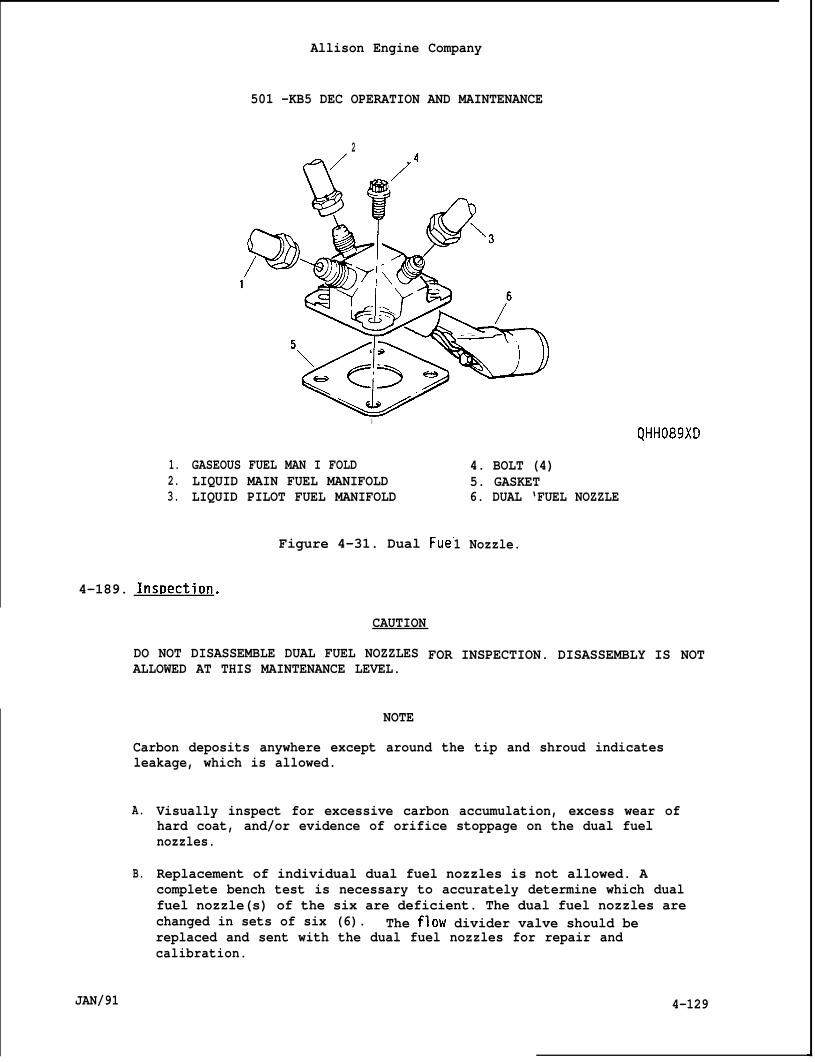
Allison Engine Company
501 -KB5 DEC OPERATION AND MAINTENANCE
2(+ /
1.2.3.
I
GASEOUS FUEL MAN I FOLDLIQUID MAIN FUEL MANIFOLDLIQUID PILOT FUEL MANIFOLD
QHH089XD
4. BOLT (4)5. GASKET6. DUAL ‘FUEL NOZZLE
Figure 4-31. Dual Fue’
4-189. Inst)ection.
CAUTION
1 Nozzle.
DO NOT DISASSEMBLE DUAL FUEL NOZZLESALLOWED AT THIS MAINTENANCE LEVEL.
NOTE
FOR INSPECTION. DISASSEMBLY IS NOT
Carbon deposits anywhere except around the tip and shroud indicatesleakage, which is allowed.
A.
B.
Visually inspect for excessive carbon accumulation, excess wear ofhard coat, and/or evidence of orifice stoppage on the dual fuelnozzles.
Replacement of individual dual fuel nozzles is not allowed. Acomplete bench test is necessary to accurately determine which dualfuel nozzle(s) of the six are deficient. The dual fuel nozzles arechanged in sets of six (6). The flow divider valve should bereplaced and sent with the dual fuel nozzles for repair andcalibration.
JAN/91 4-129
Allison Engine Company
501-KB5 DEC OPERATION AND MAINTENANCE
NOTE
Some carbor deposited around the pilot spray tip and the main jets isnormal. If there is no visible damage or hot spots in the associatedcombustion liners or turbine vanes as seen by borescope inspection, andif there are no starting problems or dark exhaust smoke, the carbon isnot interfering with the operation of the fuel nozzle and should not bedisturbed.
c.
D.
E.
Replace or clean the dual fuel nozzles if excessive smoking occursfrom the exhaust or if carbon buildup appears to be restricting ordistorting the fuel flow.
Warpage of the dual fuel nozzle air shroud or worn places through thewear coating to the bare metal along the axial portion of the airshroud the dual fuel nozzle must be replaced.
Any damaqe to the spray tip or main jets which changes fuel flowcharacte~istics or to the shroud which changes air Flowcharacteristics or to the internal screen which is suspected of beingclogged the dual fuel nozzle must be replaced.
4-190. Cleaninq.CAUTION
DO NOT DISASSEMBLE DUAL FUEL NOZZLES FORALLOWED AT THIS MAINTENANCE LEVEL.
CAUTION
CLEANING. DISASSEMBLY IS NOT
INTERNAL CLEANING OF THE FUEL FUEL NOZZLES EXCEPT AT A REPAIR CENTER ISIMPRACTICAL BECAUSE OF THE NEED FOR A QUALIFIED TECHNICIAN SPECIALIZEDEQUIPMENT AND A FLOW BENCH TEST.
NOTE
If carbon is excessive, especially that of the hard type or if air willnot flow freely from the pilot and main passages, a faulty fuel nozzleis indicated. Replacement of all six dual fuel nozzles are required.External carbon buildup, especially that of the soft type, can becleaned, and the dual fuel nozzles can continue in service.
A. Connect clean, dry shop air to each fuel inlet fitting (gaseous,pilot, and main). Maintain a steady flow of air while cleaning.
B. Hold the dual fuel nozzle at an attitude so that carbon, whenremoved, will fall clear of the dual fuel nozzle.
C. Initially attempt to clean the tip with a cotton swab.
4-130 JAN/91
\
Allison Engine Company
501-KB5 DEC OPERATION AND MAINTENANCE
CAUTION
DO NOT WIPE OR CLEAN CARBON WITH SHOPENTER THE DUAL FUEL NOZZLE ORIFICES.ALTER THE DUAL FUEL NOZZLE OPERATION.
CAUTION
TOWELS WHICH MAY ALLOW CARBON TOBLOCKAGE CAN OCCUR WHICH WILL
SCRAPERS MADE OF COPPER CAN BE USED TO CAREFULLY SCRAPE OFF THE CARBON.SCRAPING MOTION SHOULD BEGIN NEARAN ORIFICE AND MOVE AWAY SO THE CARBONFALLS FREE OF THE DUAL FUEL NOZZLE. MUCH CARE SHOULD BE TAKEN NOT TOPUSH CARBON INTO AN ORIFICE.
CAUTION
CARBON IS ABRASIVE. DO NOT CRUSH CARBON BETWEEN THE TOOL AND THESURFACE BEING RUBBED.
CAUTION
KEEP COPPER SCRAPER TOOLS SHARP AND SCRAPE JUST HARD ENOUGH TO BREAK THECARBON LOOSE.
D. If carbon can not be removed with a cotton swab, use copper scraperand carefully remove the external carbon.
4-191. Installation.
CAUTION
DUAL FUEL NOZZLES MUST BE REPLACED IN A MATCHED SET. DO NOT MIX DUALFUEL NOZZLES WITH DIFFERENT FLOW CHARACTERISTICS SUCH AS NEW AND USEDDUAL FUEL NOZZLES OR THOSE OF DIFFERENT PART NUMBER EVEN THOUGH THEYPHYSICALLY FIT. UNBALANCED FLOWS CAN CAUSE EXTENSIVE TURBINE DAMAGE.
CAUTION
DO NOT USE DUAL FUEL NOZZLES, P/N 23006598, ON WATER INJECTIONSYSTEMS.
A. Apply a light coat of antiseize compound, MIL-L-15719, or Adlube,MIL-L-25681, to the threads of the bolts (4, Figure 4-31).
B. Carefully install gasket (5) and dual fuel nozzle (6) and secure withbolts (4). Torque bolts to 70-85 lb in. (7.9-9.6 N-m). Lockwirebolts.
C. Install pilot fuel manifold (3) and torque coupling nut to 80-120 lbin. (9.0-13.5 N0m) and lockwire.
JAN/91 4-131
4-192.
4-193.
4-194.
●
●
●
4-132
D.
E.
F.
G.
Allison Engine Company
501-KB5 DEC OPERATION AND MAINTENANCE
Install main fuel manifold (2) and torque coupling nut to 200-250 lbin. (22.6-28.2 Nom) and lockwire.
Install gaseous fuel manifold (1) and torque coupling nut to 375-400lb in. (36.7-45.1 Nom) and lockwire.
Repeat Steps A. thru E. for remaining dual fuel nozz”
Preform an operational and leakage check.
es.
PRESSURE RELIEF VALVE.
Descri~tion and O~eration.
A. The pressure relief valve is mounted to the lower left side of theRAFT and is spring loaded closed.
B. The pressure relief valve is spring loaded closed and set to openabove 500 psi (3450 kPa).
C. The purpose of the pressure relief valve is to limit fuel pressure to500 psi (3450 kPa) above the bypass pressure.
D. When fuel pressure becomes high enough to overcome the pressurerelief valve spring loaded pressure (500 psi or 3450 kPa) and thebypass pressure, the pressure relief valve will relieve the excessivefuel pressure and allow the excessive fuel pressure to return to thefuel pump (Ref. Figure 4-26).
Removal.NOTE
Cap all openings to prevent contamination.
Make sure fuel and electrical systems are OFF and remain OFF untilinstallation is completed.
Have container to catch fuel leakage.
A. Remove relief valve tube (30, Figure 4-28) from adapter (34).
B. Remove fuel bypass tube (3) and relief and bypass return tube (31)from tee (35).
C. Remove socket head screws (32), retainer (33), and assemb-relief valve (36) from RAFT.
D. Remove adapter (34) from pressure relief valve (36).
ed pressure
E. Remove tee (35) from pressure relief valve (36).
JAN/91
Allison Engine Company
501-KB5 DEC OPERATION AND MAINTENANCE
4-195. Installation.
A. Install tee (35, Figure 4-28) in pressure relief valve (36) outlet.Torque tee to 200-300 lb in. (22.6-33.8 Nom).
B. Install adapter (34) in pressure relief valve (36) inlet. Torqueadapter to 200-300 lb in. (22.6-33.8 N-m).
C. Install assembled pressure relief valve (36) to RAFT, secure withretainer (33) and socket head screw (32). Torque Screws to 370-400lb in. (41.8-46.3 Nom).
D. Install relief and bypass return tube (31) and bypass fuel tube (3).Retain tee from turning and torque both coupling nuts to 325-400 lbin. (36.8 -45.1 Nom).
E. Install relief valve tube (30) to adapter (34). Retain adapter fromturning and torque tube’s coupling nut to 325-400 lb in.Nom). -
F. Pressurize fuel system and inspect pressure relief valveconnections for leaks.
4-196. PARALLEL AIR CONTROL VALVE.
4-197. Descri~tion and O~eration.
A.
B.
c.
D.
E.
The parallel air control valveleft side of the RAFT and is a
The r)arallel air control valve
(37, Figure 4-28) locatednormally closed valve.
is a three way electrical
(36.8 -45.1
and fitting
on the lower
operatedsolenoid with an explosion proof housing to control the air toparallel valve.
The electrical connections connect to the RAFT electrical junctionbox terminals (28 and 33, Figure 4-29).
The parallel air control valve is normally not used and RAFT outletwith be capped.
If removal and installation are required, refer to GeneralMaintenance, Section 14, for torques.
4-198. GASEOUS FUEL PURGE VALVES.
4-199. Description and O~eration.
A. The gaseous fuel purge valves are located on lower left .center of theRAFT.
JAN/91 4-133
4-200.
●
●
●
●
●
B.
c.
D.
Allison Engine Company
501-KB5 DEC OPERATION AND MAINTENANCE
The gaseous fuel purge valves are a normally closed electricalsolenoid operated valve. The electrical operation is control by thecontrol system.
The purpose of gaseous fuel purge valves are to allow purging of theliquid fuel through check valves when operating on gaseous fuel.
The gaseous fuel purge valves inlet ports are install to the leftopposite the gaseous-fuel flow to prevent liquid fuel enteringgaseous fuel system when operating on liquid fuel in case of a checkvalve failure (16 and 23, Figure 4-29).
Removal.
NOTE
Record position of fittings and tubes for installation.
Make sure fuel and electrical systems are OFF and remain OFF untilinstallation is completed.
Cap all openings to prevent contamination.
Have a container to catch fuel leakage.
Removal only the damage gaseous fuel purge valve.
A.
B.
c.
D.
E.
F.
4-201.
A.
4-134
Disconnect the required gaseous fuel purge valve’s (45, Figure 4-28)electrical connections from RAFT junction box terminals (27 and 32,Figure 4-29).
Remove the required gaseous purge tube (38, Figure 4-28).
Remove gaseous U tube (39) at the damage gaseous fuel purge valve(45) .
Remove crossover tube (42) from tee (43).
Remove the required socket head screws (40), lockwashers (41), andassembled gaseous fuel purge valve (45) from RAFT bracket.
If required, remove tee(s) (43) and/or adapter (44) from gaseous fuelpurge valve (45), recording position for installation.
Installation.
If required, install adapter (44, Figure 4-28) and tee(s) (43) ongaseous fuel purge valve (45), to position recorded on removal.Torque tee and/or adapter to 200-300 lb in. (22.6-33.8 N-m).
JAN/91
I
4-202.
4-203.
4-204.
●
●
●
JAN/91
Allison Engine Company
501-KB5 DEC OPERATION AND MAINTENANCE
B. Install assembled gaseous fuel purge (45) with inlet port to theleft, secure with lockwashers (41) and socket head screws (40).Torque screws to 35-40 lb in. (4.0-4.5 N-m).
C. Install crossover tube (42) to inlet tees (43). Torque tube’scoupling nuts to 325-400 lb in. (36.8-45.1 N6m).
D. Install outlet gaseous U tube (39) to outlet tee (43) and/or adapter(42) . Retain outlet tee or adapter from turning and torque tube’scoupling nut(s) to 325-400 lb in, (36.8-45.1 Nom).
E. Install gaseous purge tube (38) to inlet tee (43). Retain tee fromturning and torque tube’s coupling nut to 325-400 lb in. (36.8-45.1Nom).
F. Connect gaseous fuel purge valve’s electrical connections to RAFTjunction box terminals (27 and 32, Figure 4-29).
G, Perform operation and leakage test.
LIQUID FUEL OUTLET BYPASS VALVE.
Description and ODeration.
A. The liquid fuel outlet bypass valve (outlet bypass valve) is locatedon the left center of the RAFT.
B. The outlet bypass valve is normally open electrical operated solenoidvalve which is electrically controlled by the control system to allowthe liquid fuel to be bypass back to the liquid fuel pump inlet, whenoperating on gaseous fuel.
C. When operating on liquid fuel, the outlet bypass valve iselectrically closed by the control system.
Removal.
NOTE
Make sure fuel and electrical systems are OFF and remain OFF untilinstallation is completed.
Cap all openings to prevent contamination.
Have a container to catch fuel leakage.
A. Remove liquid fuel outlet bypass valve’s (outlet bypass valve)electrical connections from RAFT junction box terminals (26 and 31,Figure 4-29).
4-135
4-205.
4-206.
4-207.
4-136
Allison Engine Company
501-KB5 DEC OPERATION AND MAINTENANCE
B. Remove bypass tube (15, Figure 4-28) from outlet bypass valve (50).
C. Remove outlet bypass tube (46) from outlet bypass valve (50).
D. Remove socket head screws (47), lockwashers (48), and assembledoutlet bypass valve (50) from RAFT bracket.
E. If required, remove adapters (49) from outlet bypass valve (50).
Installation.
A.
B.
co
D.
E.
F.
If required, install adapters (49, Figure 4-28) in outlet bypassvalve (50). Torque adapters to 200-300 lb in. (22.6-33.8 Nom).
Install assembled outlet bypass valve (50) with inlet pot to the lefton RAFT bracket and secure with lockwashers (48) and socket headscrews (47). Torque screws to 35-40 lb in. (4.0-4.5 N“m).
Install outlet bypass tube (46) to the outlet bypass valve (50)outlet adapter (49). Retain outlet adapter from turning and torquetube’s coupling nut to 325-400 lb in. (36.8-45.1 N-m).
Install bypass tube (15) to the outlet bypass valve (50) inletadapter (49). Retain the inlet adapter from turning and torquetube’s coupling nut to 325-400 lb in. (36.8-45.1 N“m).
Connect outlet bypass valve (50) electrical leads to RAFT junctionbox terminals (26 and 31, Figure 4-29).
Perform an operation and leakage test.
LIQUID FUEL HEATING BYPASS VALVE.
Descri~tion and O~eration.
A. The liquid fuel heating bypass valve (heating bypass valve) islocated on lower center of the RAFT.
B. The heating bypass valve is normally open electrical operatedsolenoid valve which is electrically controled by the control systemto allow the liquid fuel to be bypass to a heat exchanger for heatingthe liquid fuel in cold weather for engine starting. It will alsoopen allowing the liquid fuel to be bypassed back to inlet side ofthe liquid fuel pump when operating on gaseous fuel.
C. The heat exchanger is an option and may not be installed. The liquidfuel can still be heated by bypassing the liquid fuel using the fuelflow friction to heat the liquid fuel. This method will take moretime to heat the liquid fuel for starting the engine.
JAN/91
Allison Engine Company
501-KB5 DEC OPERATION AND MAINTENANCE
4-208. Removal.NOTE
● Make sure fuel and electrical systems are OFF and remain OFF untilinstallation is completed.
. Cap all openings to prevent contamination.
● Have a container to catch fuel leakage.
A. Disconnect heating bypass valve (58, Figure 4-28) electricalconnection from RAFT junction box terminals (26 and 31, Figure 4-29).
B. Remove fuel supply tube (2, Figure 4-28) from tee (51).
C. Remove incoming fuel supply tube (52) from tee (51).
D. Remove heating bypass tube (53) from outlet adapter (57).
E. Remove socket head screws (54), lockwashers (55), and assembledheating bypass valve (58) from RAFT bracket.
NOTE
Record position of tee for installation.
F. If required, remove tee (51) and adapters (56 and 57) from heatingbypass valve (58).
4-209. Installation.
A.
B,
c.
D.
E.
F.
If required, install adapter (57, Figure 4-28) in heating bypassvalve (58) outlet port and torque adapter to 200-300 lb in.(22.6 -33.8 Nom).
If required, install adapter (56) in heating bypass valve (58) inletport and torque adapter to 200-300 lb in. (22.6-33.8 N-m).
If required, install tee (51) on inlet adapter (56) to positionrecorded on removal.
Install assembled heating bypass valve (58) to RAFT bracket, securewith lockwashers (55) and socket head screws (54). Torque screws to35-40 lb in. (4.0-4.5 Nom).
Install heating bypass tube (53) to outlet adapter (57). Retainadapter from turning and torque tube’s coupling nut to 325-400 lb in.(36.8 -45.1 N-m).
Install incoming fuel supply tube (52) to tee (51). Retain tee fromturning and torque tube’s coupling nut to 475-575 lb in, (53.7-64.9N-m).
JAN/91 4-137
Allison Engine Company
501-KB5 DEC OPERATION AND MAINTENANCE
4-210.
4-211.
4-212.
●
●
●
4-138
G. Install fuel supply tube (2) to tee (51). Retain tee from turningand torque tube’s coupling nut to 475-575 lb in. (53.7-64.9 N.m).
H. Connect heating bypass valve (58) electrical connections to RAFTjunction box terminals (26 and 31, Figure 4-29).
I. Perform an operation and leakage test.
LIQUID FUEL PRESSURE SWITCH.
Descrit)tion and Operation.
A. The liquid fuel pressure switch is located on the upper right connectto junction box of the RAFT.
B. The purpose of the liquid fuel pressure switch is to indicate thatthe liquid fuel pressure is more than 50 psig (345 kPag), even whenoperating on gaseous fuel and the off engine mounted liquid fuel pumpis operating.
C. The liquid fuel pressure switch will give a signal (indication) whenthe liquid fuel pressure drop below 40 psig (276 kPag).
D. The liquid fuel pressure switch will actuated on increasing pressureof 50 t 5 psig (345 t 34.5 kPag) moving the contact from the brown tored contacts to brown to blue contacts. On deceasing pressure theliquid fuel pressure will be actuated at 40 t 5 psig (276 t 34.5kPag) moving the contact from brown to blue to brown to red contacts,de-energize the starter circuit.
E. The liquid fuel pressure switch’s electrical leads connects to theRAFT junction box terminals as follows (Ref. Figure 4-29).
1. Green lead (Ground) to terminals 29.
2. Red lead to terminal 24,
3. Brown lead to terminal 23.
4. Blue lead to terminal 22.
Removal.NOTE
Make sure fuel and electrical systems are OFF and remain OFF untilinstallation is completed.
Cap all openings to prevent contamination.
Have a container to catch fuel leakage.
JAN/91
4-213.
4-214.
4-215.
4-216.
4-217.
Allison Engine Company
501-KB5 DEC OPERATION AND MAINTENANCE
A. Disconnect liquid fuel pressure switch (59, Figure 4-28).
B. Remove pressure switch tube (14) from liquid fuel pressure switch(59) .
C. Remove liquid fuel pressure switch (59) from electrical junction box(29) .
Installation.
A.
B.
c.
D.
Install liquid fuel pressure switch (59, Figure 4-28) to electricaljunction box (29).
Install pressure switch tube (14) to liquid fuel pressure switch(59). Retain pressure switch from turning and torque tube’s couplingnut to 35-40 lb in. (4.0-4.5 Nom).
Install liquid fuel pressure switch (59, Figure 4-28) to RAFTelectrical junction box (29) terminals (Ref. Figure 4-29):
1. Green lead (Ground) to terminal 29.
2. Red lead to terminal 24.
3. Brown lead to terminal 23.
4. Blue lead to terminal 22.
Perform an operation and leakage test.
GASEOUS FUEL SHUTOFF AND VENT VALVES.
Descrir)tion and O~eration.
A.
B.
c.
D.
The dual fuel system gaseous fuel has two inlet gaseous fuel shutoffvalves and a vent valve (Ref. Figure 4-26).
The two gaseous fuel shutoff valves are used to make sure gaseousfuel supply is completely shutoff and a vent valve is used to vent(remove) to gaseous fuel pressure from between the shutoff valves.
For complete description and operation, refer to the OEM manual(s).
For removal and installation instructions refer to the OEM manual(s).
GASEOUS FUEL FILTER.
Descri~tion and ODeration.
A. The gaseous fuel filter is located on right center of the RAFT.
JAN/91 4-139
Allison Engine Company
501 -KB5 DEC OPERATION AND MAINTENANCE
B. The gaseous fuel filter is sometimes called the final filter and isthe final filtration of the gaseous fuel before entering the gaseousfuel metering valve.
C. The normal filtration rating is 2 microns with a 10 micron absolute.
D. The filter element is removable and cleanable.
4-218. Removal.NOTE
. Make sure fuel and electrical systems are OFF and remain OFF untilinstallation is completed.
. Cap all openings to prevent contamination.
A. Remove gaseous fuel supply hose (60, Figure 4-28) from elbow (61).
B. Remove gaseous fuel filter inlet pressure tube (62) from elbow (61).
C. Remove bolts (63), lockwashers (64), hex head screws (69),lockwashers (70), retainer (71), and assembled gaseous fuel filter(74). Remove and discard gasket (65).
D. If required, loosen nut (66) and remove nut (66), O-ring (67), andadapter assembly (68) from gaseous fuel filter (74). Discard O-ring.
E. If required, loosen nut (72) and remove nut (72), O-ring (73), andelbow (61) from gaseous fuel filter (74). Discard O-ring.
4-219. Installation.
A.
B.
c.
D.
4-140
If required, install nut (72, Figure 4-28) and O-ring (73) on elbow(61) and install elbow in gaseous fuel filter (74) inlet port. Donot tighten nut (71) now.
If required, install nut (66), and O-ring (67) on adapter assembly(68) and install adapter assembly in gaseous fuel filter (74) outletport. Do not tighten nut (66) now.
Install assembled gaseous fuel filter (74) and adapter assembly (68)to gaseous FMV (94) and RAFT, with gasket (65) and secure withlockwashers (64), bolts (63), retainer (71), lockwashers (70) and hexhead screws (69). Torque bolts (63) to 70-85 lb in. (8.0-9.6N-m). Torque hex head screws (69) to 205-245 lb in. (23.6-27.6Nom). Tighten nut (66).
Install gaseous fuel supply hose (60) to elbow (61). Retain elbowfrom turning and torque hose’s coupling nut to 1200-1500 lb in. or100-125 lb ft. (135.6-169.4 N*m). Tighten nut (72).
JAN/91
4-220.
4-221.
4-222.
●
●
JAN/91
E.
F.
Allison Engine Company
501-KB5 DEC OPERATION AND MAINTENANCE
Install gaseous fuel filter inlet pressure tube (62) to elbow (61).Torque tube’s coupling nut to 35-40 lb in. (4.0-4.5 Nom).
Perform operation and leakage test.
GASEOUS FUEL METERING VALVE (FMV).
Descri~tion and Operation.
A.
B.
c.
D.
The explosion proof gaseous fuel metering valve (FMV) is located onthe lower right of the RAFT.
The gaseous FMV meters the gaseous fuel to the engine in accordancewith voltage inputs from the control system. Gaseous fuel issupplied to the gaseous FMV at a regulated pressure. The gaseous FMVis a balanced force type which is positioned by a proportionalsolenoid assembly with an integral servo system.
The gaseous FMV is positioned as a function of the input commandvoltage (O to 5 volts) from the control system. A feedback voltagefrom a linear variable differential transformer (LVDT) proportionalto valve position (metering area) is provided within gaseous FMV.The voltage is compared to the O to 5 volts input command signal fromthe control system. The current in the proportional solenoid isvaried until the position signal equals the command input. If theposition and/or feed back voltage varies 0.5 vdc from each other afuel system malfunction will occur.
A check valve is installed on qaseous FMV outlet to Drevent reversegaseous fuel flow.
Removal.NOTE
Make sure fuel and electrical svstems are OFF and remain OFF untilinstallation is completed. -
Cap all openings to prevent contamination
A. Remove gaseous FMV (94, Figure 4-28) e“electrical junction box (29) terminals
1. Brown lead from terminal 42.
2. Yellow lead from terminal 43.
3. Green lead from terminal 44.
4. Violet lead from terminal 45.
ectrical leads from the RAFTas follows (Ref. Figure 4-29):
4-141
B.
c.
D.
E.
F.
G.
H.
I.
J.
.
Allison Engine Company
501-KB5 DEC OPERATION AND MAINTENANCE
5. Blue lead from terminal 46.
6. Red lead from terminal 47.
7. Orange lead from terminal 48.
Remove gaseous fuel filter per Paragraph 4-218.
Remove gaseous fuel manifold hose (75, Figure 4-18) from elbow (76).
Remove gaseous fuel to tee tube (77) from outlet adapter (86).
Remove gaseous fuel filter outlet pressure tube (78) from gaseous FMV(94) inlet.
~:~~[e pressure switch and gage tube (79) from gaseous FMV (94).
Remove hex head screw (80), lockwashers (81), and assembled gaseousFMV (94) from RAFT.
If required, remove hex head screws (82), lockwashers (83), flange(84), gasket (85), and elbow (76) from outlet adapter (86). Discardgasket.
If required, remove hex head screws (87), lockwashers (88), gasket(89), and outlet adapter (86) from check valve (90). Discard gasket.
If required, remove hex head screws (91), lockwashers (92), gasket(93), and check valve (90) from gaseous FMV (94). Discard gasket.
4-223. Clean. InsDeCt. Test and ReDair. Clean, inspect, test, and repair perParagraphs 4-7 to 4-9.
4-224. Installation.NOTE
Make sure check valve is installed to prevent reverse flow.
A. If required, install gasket (93, Figure 4-28) and check valve (90) togaseous FMV (94) outlet port and secure with lockwashers (92) and hexhead screws. Torque screws to 70-85 lb in. (8.0-9.6 Nom).
B. If required, install gasket (89) and outlet adapter (86) to checkvalve (90) and secure with lockwashers (88) and hex head screws(87) . Torque screws to 70-85 lb in. (8.0-9.6 N-m).
C. If required, install gasket (85), elbow (76), and flange (84) tooutlet adapter (86) and secure with lockwashers (83) and hex head
4-142 JAN/91
—.
D.
E.
F.
G.
H.
I.
J.
K.
Allison Engine Company
501 -KB5 DEC OPERATION AND MAINTENANCE
screws (82). Do not tighten or torque screws (82) allow elbow (76)to turn.
Install assembled gaseous FMV (94) to RAFT and secure withlockwashers (81) and hex head screws (80). Torque screws to 120-150lb in. (13.6-16.9 N”m).
Install gaseous fuel manifold hose (75) to elbow (76). Torque hexhead screws (82) to 70-85 lb in. (8.0-9.6 N-m). Retain elbow fromturning hose’s coupling nut to 1200-1500 lb in. or 100-125 lb ft.(135.6 -169.4 Nom).
Install pressure switch and gage tube (79) to gaseous FMV (94)inlet. Torque tube’s coupling nut to 80-120 lb in. (9.0-13.5 Nom).
Install gaseous fuel filter outlet pressure tube (78) to gaseous FMV(94) inlet. Torque tube’s coupling nut to 80-120 lb in. (9.3-13.5N$m).
Install gaseous fuel to tee tube (77) to outlet adapter (86). Torquetube’s coupling nut to 325-400 lb in. (36.8-45.1 N-m).
Install gaseous fuel filter per Paragraph 4-219.
Connect gaseous FMV (94) electrical leads to the RAFT electricaljunction box (29) terminals as follows (Ref. Figure 4-29):
1.
2.
3.
4.
5.
6.
7.
Brown lead to terminal 42.
Yellow lead to terminal 43.
Green lead to terminal 44.
Violet lead to terminal 45.
Blue lead to terminal 46.
Red lead to terminal 47.
Orange lead to terminal 48.
Perform an operation and leakage test.
4-225. GASEOUS DIFFERENTIAL PRESSURE SWITCH.
4-226. Descri~tion and Ot)eration.
A. The gaseous differential pressure switch is located on the lowerright of the RAFT.
JAN/91 4-143
Allison Engine Company
501-KB5 DEC OPERATION AND MAINTENANCE
B. The gaseous differential pressure switch measure gaseous fuelpressure before (inlet) and after (outlet) the gaseous fuel filter.If the gaseous fuel filter’s outlet fuel pressure is less than 20 t 2psig (138 f 13.8 kPag) than the inlet fuel pressure (differentialpressure) the gaseous differential pressure switch will give a signalthat the gaseous fuel filter is becoming clogged (dirty).
C. The gaseous differential pressure switch electrical lead connect tothe RAFT electrical junction box terminals.
4-227. Removal.
NOTE
. Make sure fuel and electrical systems are OFF and remain OFF untilinstallation is completed.
. Cap all openings to prevent contamination.
A. Remove gaseous differential pressure swelectrical leads at the RAFT electricalas follows (Ref. Figure 4-29):
1. Green lead from terminal 29.
2. Blue lead from terminal 49.
3. Brown lead from terminal 50.
4. Red lead from terminal 51.
tch (98, Figure 4-28)junction box (29) terminals
B. Remove gaseous fuel filter inlet pressure tube (62, Figure 4-28) fromgaseous differential pressure switch (98) high port adapter (97).
C. Remove gaseous fuel filter outlet pressure tube (78) from gaseousdifferential pressure switch (98) low port adapter (97).
D. Remove hex head screws (95), lockwashers (96), and gaseousdifferential pressure switch (98) from RAFT.
E. If required, remove adapters (97) from gaseous differential pressureswitch (98).
4-228. Installation.
A. If required, install adapters (97, Figure 4-28) in low and high portsof the gaseous differential pressure switch (98). Torque adapters to35-40 lb in. (4.0-4.5 Nom).
4-144 JAN/91
Allison Engine Company
501-KB5 DEC ‘OPERATION AND MAINTENANCE
B. Install assembled gaseous differential pressure switch (98) to RAFTand secure with lockwashers (96) and hex head screws (95). Torquescrews to 60-65 lb in. (6.8-7.3 Nom).
C. Install gaseous fuel filter outlet pressure tube (78) to gaseousdifferential pressure switch (98) low port adapter (97). Retainadapter from turning and torque tube’s coupling nut to 80-120 lb in.(9.0 -13.5 N-m).
D. Install gaseous fuel filter inlet pressure tube (62) to gaseousdifferential pressure switch (98) high port adapter (97). Retainadapter from turning and torque tube’s coupling nut to 80-120 lb in.(9.0 -13.5 Nom).
E. Connect electrical leads of gaseous differential pressure switch (98)to RAFT electrical junction box (29) terminals as follows (Ref.Figure 4-29):
1. Green lead to terminal 29.
2. Blue lead to terminal 49.
3. Brown lead to terminal 50.
4. Red lead to terminal 51.
F. Perform operation and leakage test,
4-229. GASEOUS FUEL PRESSURE SWITCH.
4-230. Description and O~eration.
A. The gaseous fuel pressure switch is located on the RAFT electricaljunction box.
B. The purpose of gaseous fuel pressure is to give a signal that lessthan 10 psig (69 kPag) of gaseous fuel pressure in the gaseous fuelsystem. If initiating an engine start when operating on gaseous fueland more than 10 psig (69 kPag) is in the gaseous fuel system, asignal is sent to the control system and the control system willde-energize the starter and ignition system to prevent damage to theengine.
C. The operating pressures on gaseous fuel pressure switch is 10 ~ 2psig (69 t 13.8 kPag).
D. The gaseous fuel pressure switch electrical terminals connects to theRAFT junction box terminals.
JAN/91 4-145
Allison Engine Company
‘501-KB5 DEC OPERATION AND MAINTENANCE
4-231. Removal.NOTE
● Make sure fuel and electrical systems are OFF and remain OFF untilinstallation is completed.
● Cap all openings to prevent contamination.
A. Disconnect gaseous fuel pressure switch (100, Figure 4-28) electricalleads from RAFT electrical .iunction box (291 terminals as follows(Ref. Figure 4-29): -
.,
1.
2.
3.
4.
Blue lead from terminal 19.
Brown lead from terminal 20.
Red lead from terminal 21.
Green lead from terminal 29.
B. Remove gaseous pressure switch tube (99, Figure 4-28)fuel pressure switch (100).
C. Remove gaseous fuel pressure switch (100) from electrbox (29).
from gaseous
cal junction
D. If required, remove adapter from gaseous fuel pressure switch (100).
4-232. Installation.
A.
B.
c.
D.
4-146
If required, install adapter on gaseous fuel pressure switch (100,Figure 4-28).
Install gaseous fuel pressure switch (100) to RAFT electricaljunction box (29).
Install gaseous pressure switch tube (99) to gaseous fuel pressureswitch (100). Retain adapter from turning and torque tube’s couplingnut to 80-120 lb in. (9.0-13.5 Nom).
Connect electrical leads of gaseous fuel pressure switch (100) toRAFT electrical junction box (29) terminals as follows (Ref. Figure4-29) :
1.
2.
3.
4.
Blue lead to terminal 19.
Brown lead to terminal 20.
Red lead to terminal 21.
Green lead to terminal 29.
JAN/91
4-233.
4-234.
4-235.
●
●
●
JAN/91
Allison Engine Company
501-KB5 DEC OPERATION AND MAINTENANCE
E. Perform operation and leakage test.
GASEOUS FUEL MANIFOLD AND HOSES.
Description and ODeration.
A. The gaseous fuel manifold connects gaseous fuel from the RAFT gaseousfuel hose to the fuel manifold tubes.
B. The six gaseous fuel manifold tubes connects gaseous fuel from thegaseous fuel manifold to the fuel nozzles.
C. The gaseous fuel manifold and tubes are located on the engine.
Gaseous Fuel Manifold Removal.
NOTE
Make sure fuel and electrical systems are OFF andinstallation is completed.
Cap all openings to prevent contamination.
Record position of gaseous fuel manifold tubes, c“for installation.
A. Remove RAFT gaseous fuel hose (1, Figure 4-32)
remain OFF until
amps, and brackets
from elbow (2).
B. Remove bolts (3), washers (4), flange (5), gasket (6), nuts (7), andgaseous fuel manifold (8) from gaseous manifold bracket (15).
C. Remove six gaseous fuel manifold tubes (9) from gaseous fuel manifold(8). If required, remove bolt (22), nut (23), and clamp (24) frombracket (25).
D. Remove bolt (10) and nut (11) holding clamp (12) to 90° bracket (14)and remove gaseous fuel manifold (8).
E. If required, remove clamp (12) from gaseous fuel manifold (8).
F. If required, remove nut (13), and 90” bracket (14) from engine.
G. If required, remove bolts (16), washers (17), nuts (18), and gaseousmanifold bracket (15) from engine bracket (19).
H. If required, remove nuts (20), washers (21), and engine bracket (19)from engine.
4-147
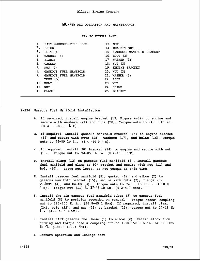
Allison Engine Company
501-KB5 DEC OPERATION AND MAINTENANCE
KEY TO FIGURE 4-32.
1. RAFT GASEOUS FUEL HOSE 13. NUTELBOW
:: BOLT (44. WASHER5. FLANGE6. GASKET7. NUT (4)8. GASEOUS9. GASEOUS
TUBE (6;10. BOLT11. NUT12. CLAMP
14. BRACKET 90°15. GASEOUS MANIFOLD BRACKET
4) 16. BOLT (3)17. WASHER (3)18. NUT (3)19. ENGINE BRACKET
FUEL MANIFOLD 20. NUT (3)FUEL MANIFOLD 21. WASHER (3)
22. BOLT23. NUT24. CLAMP25. BRACKET
2-236. Gaseous Fuel Manifold Installation.
A.
B.
c.
D.
E.
F.
G.
H.
4-148
If required, install engine bracket (19, Figure 4-32) to engine andsecure with washers (21) and nuts (20). Torque nuts to 74-85 lb in.. .(8.4 -10.0 N“m). -
If required, install(19) and secure withnuts to 74-89 lb in.
If required, install(13). Torque nut to
gaseous manifold bracket (15) to engine bracketnuts (18), washers (17), and bolts (16). Torque(8.4 -10.0 N“m).
90° bracket (14) to engine and secure with nut74-85 lb in. (8.4-10.0 N“m).
Install clamp (12) on gaseous fuel manifold (8). Install gaseousfuel manifold and clamp to 90” bracket and secure with nut (11) andbolt (10). Leave nut loose, do not torque at this time.
Install gaseous fuel manifold (8), gasket (6), and elbow (2) togaseous manifold bracket (15), secure with nuts (7), flange (5),~a;~ers (4), and bolts (3). Torque nuts to 74-89 lb in. (8.4-10.0. . Torque nut (11) to37-42 lb in. (4.2-4.7 Nom).
Install the six gaseous fuel manifold tubes (9) to gaseous fuelmanifold (8) to position recorded on removal. Torque hoses’ couplingnut to 325-400 lb in. (36.8-45.1 Nom). If required, install clamp(24), bolt (22), and nut (23) to bracket (25), torque nut to 37-42 lbin. (4.2-4.7 Nom).
Install RAFT gaseous fuel hose (1) to elbow (2). Retain elbow fromturning and torque hose’s coupling nut to 1200-1500 lb in. or 100-125lbft. (135.6-169.4 N”m).
Perform operation and leakage test.
JAN/91
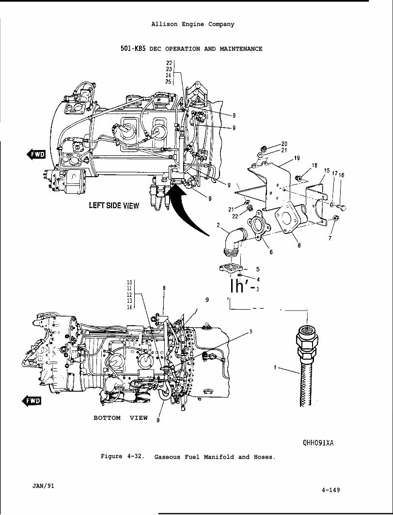
Allison Engine Company
501-KB5 DEC OPERATION AND MAINTENANCE
x24 L
d— 5~ +4
1011
h-l
8 l h ’ - 31213 9 ’14 / I__ - — . I
JAN/91
9
1
I
BOTTOM VIEW (
QHH091XA
Figure 4-32. Gaseous Fuel Manifold and Hoses.
4-149
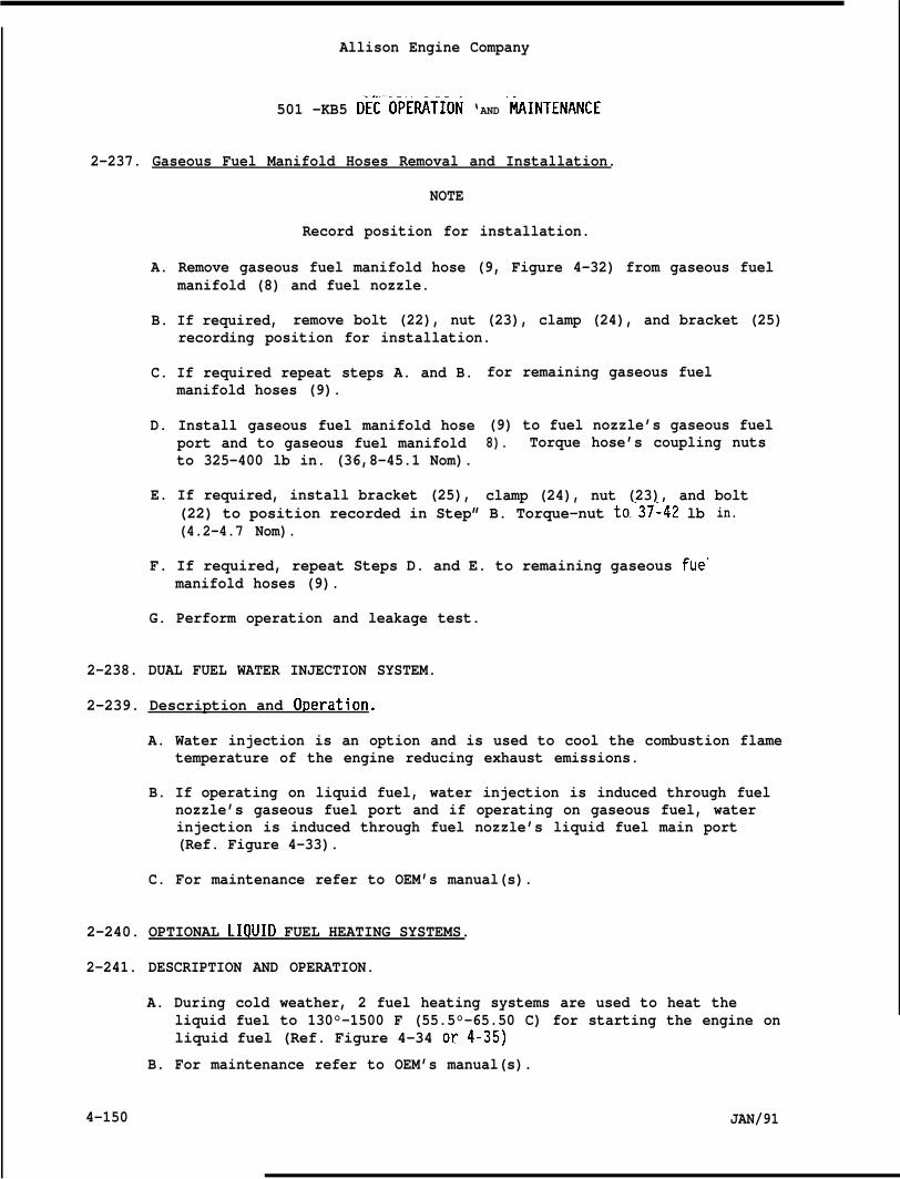
Allison Engine Company
. . ..— —501 -KB5 Dic oWifioN ‘AND “tiINTENANCE
2-237. Gaseous Fuel Manifold Hoses Removal and Installation.
NOTE
Record position for installation.
A. Remove gaseous fuel manifold hose (9, Figure 4-32) from gaseous fuelmanifold (8) and fuel nozzle.
B. If required, remove bolt (22), nut (23), clamp (24), and bracket (25)recording position for installation.
C. If required repeat steps A. and B.manifold hoses (9).
D. Install gaseous fuel manifold hoseport and to gaseous fuel manifoldto 325-400 lb in. (36,8-45.1 Nom).
E. If required, install bracket (25),
for remaining gaseous fuel
(9) to fuel nozzle’s gaseous fuel8). Torque hose’s coupling nuts
clamp (24), nut (23), and boltin.(22) to position recorded in Step” B. Torque-nut to37~42 lb
(4.2-4.7 Nom).
F. If required, repeat Steps D. and E. to remaining gaseous fue<manifold hoses (9).
G. Perform operation and leakage test.
2-238. DUAL FUEL WATER INJECTION SYSTEM.
2-239. Description and O~eration.
A. Water injection is an option and is used to cool the combustion flametemperature of the engine reducing exhaust emissions.
B. If operating on liquid fuel, water injection is induced through fuelnozzle’s gaseous fuel port and if operating on gaseous fuel, waterinjection is induced through fuel nozzle’s liquid fuel main port(Ref. Figure 4-33).
C. For maintenance refer to OEM’s manual(s).
2-240. OPTIONAL LIOUID FUEL HEATING SYSTEMS.
2-241. DESCRIPTION AND OPERATION.
A. During cold weather, 2 fuel heating systems are used to heat theliquid fuel to 130°-1500 F (55.5°-65.50 C) for starting the engine onliquid fuel (Ref. Figure 4-34 or4-35)
B. For maintenance refer to OEM’s manual(s).
4-150 JAN/91
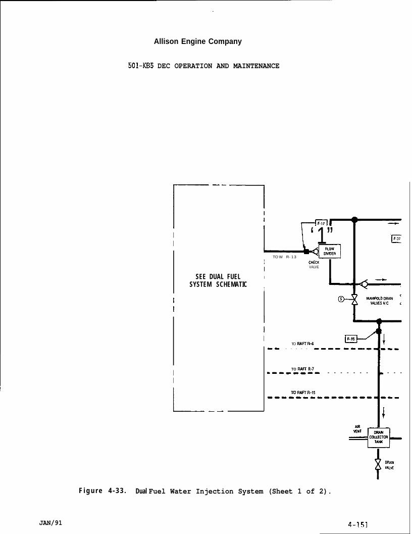
Allison Engine Company
JAN/91
501-KB5 DEC OPERATION AND MAINTENANCE
r--lII
II
SEE DUAL FUELSYSTEM SCHEMATIC
I1
E\ ‘1”I
T O W R - 1 3 J4zlCNECK
IVALVE
I
I
O-is MANIFOLODR41N rVPMISNC L
II
L.—
II -!F-15
TO llA~ % 1-9 - - - - - ---- 9-- ---.
TO RAW R-71--O------ - - - - - - - - - - -
*
II DRAINwvE
F i g u r e 4 - 3 3 . Dual Fuel Water Injection System (Sheet 1 of 2).
4-151
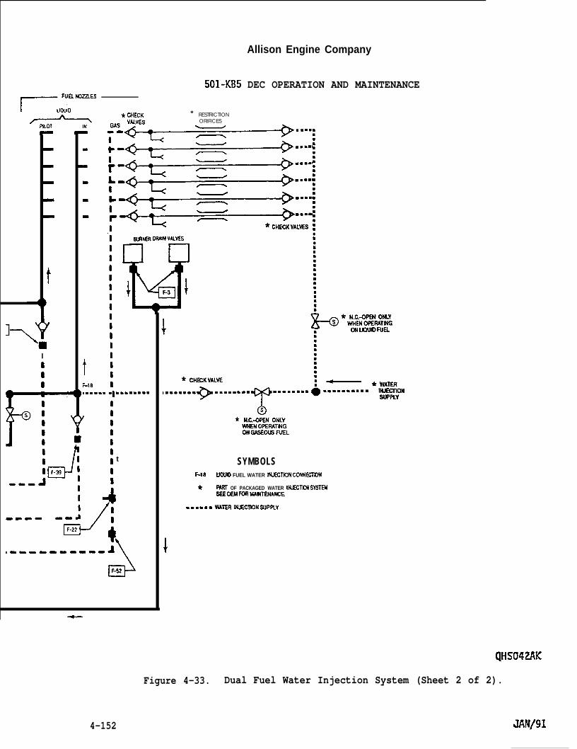
Allison Engine Company
■
■
8
m
II1I
--
t:-1.9
501-KB5 DEC OPERATION AND MAINTENANCE
RESTRICTIONORIFICES
* CHECK *
WRNER OWN VWES
,..... q .m.. m.m.
1$It t
I1
G’F-52
●
m●
9
SYMBOLSF-18 UOOID FUEL WATER NUECTION CONKCTSJN
* PMIT OF PACKAGED WATER IN.IECT!ON SYSTEMSSSOEM FOR MUNTENA*E
.mm,=m WATER ltMXTIONWPFtY
QHS042AK
Figure 4-33. Dual Fuel Water Injection System (Sheet 2 of 2).
4-152
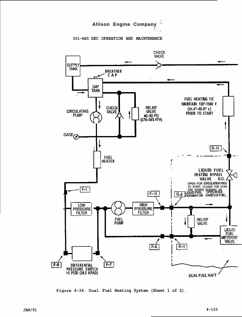
Allison Engine Company “:.!. . .
501-KB5 DEC OPERATION AND MAINTENANCE
:;::;
syw~Y~ ~
BREATHER.~ C A P
t
1
1 FUELHEATER
1
/’n.F-6 DIFFERENTIALPRESSURE SWITCH>5 PSID (34.5 KPAD)
Figure 4-34. Dual
JAN/91
El\
--l
FUEL HEATING T/C
+MAINTAIN 130°-1500 F
(54.4=65.6’3 c)PRIOR TO START 1
r. - — .-—-- —
1
I
LIQUID FUEL THEATING BYPASS
VALVE N.O. iI OPEN FOR CIROUIATIDN PRIOI TO START. CLOSED FOR STAR
In
AND DURING RUNNING ON
R+ ##iDN~~h ~~\!$&!kIEL/
\1
HIGH 1 / ~PRE;:IRE
-
1FUELPUMP
J
—
\mF-7
Fuel Heating System (Sheet 1 of 2).
4-153
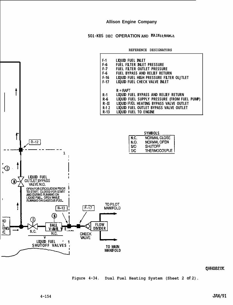
t
t
-4-
)-HI--- -— -- — --
1
I II
R,
LIQUID FUEL Is OU;~W;3’Y~ASS
. . I
t
t
—
Allison Engine Company
501-KB5 DEC OPERATION AND MAIN IkNANLk
REFERENCE DESIGNATORS
F-1F-6F-7F-6F-16F-17
R-1R-6R-I IR-1 2R-13
LIQUID FUEL INLETFUEL FILTER INLET PRESSUREFUEL FILTER OUTLET PRESSUREFUEL BYPASS AND RELIEF RETURNLIQUID FUEL HIGH PRESSURE FILTER OLJTLETLIQUID FUEL CHECK VALVE INLET
R = RAHLIQUID FUEL BYPASS AND RELIEF RETURNLIQUID FUEL SUPPLY PRESSURE (FROM FUEL PUMP)LIQUID FUEL HEATING BYPASS VALVE OUTLETLIQUID FUEL OUTLET BYPASS VALVE OUTLETLIQUID FUEL TO ENGINE
/mF?&I
s,
BALL FLOW
N.C. V A L V E _ DIVIDERN.C.
v‘ 1
fl-11-l;(
LIQUID FUELSHUTOFF VALVES I
~
TO MAINMANIFOLD
SYMBOLS
m
QHif082XK
Figure 4-34. Dual Fuel Heating System (Sheet 2 of 2).
4-154
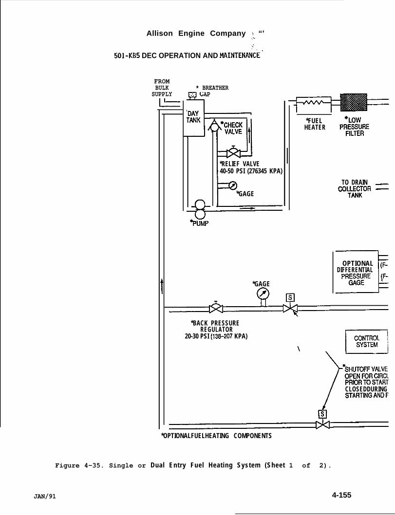
Figure 4-35. Single or
FROMBULK
SUPPLYk
* BREATHERCAP
4
. . .
-J /
Allison Engine Company ; “’.:
501-KB5 DEC OPERATION AND MAINTEtiCE-
1*RELIEF VALVE40-50 PSI (276345 KPA)
P*GAGE
*FUELHEATER
TO DRAINCOUEECJOR
OPTIONAL ~DIFFERENTIAL
LPRES::RE (F-
*GAGE
*BACK PRESSUREREGULATOR
20-30 PSI (13B-207 KPA)
\ F,~.
OPENFORCIRClPRIORTOSTARTCLOSEDDURINGSTARTINGANDF
*OPTIONALFUELHEATING COMPONENTS
Dual Entry Fuel Heating System (Sheet 1 of 2).
JAN/91 4-155
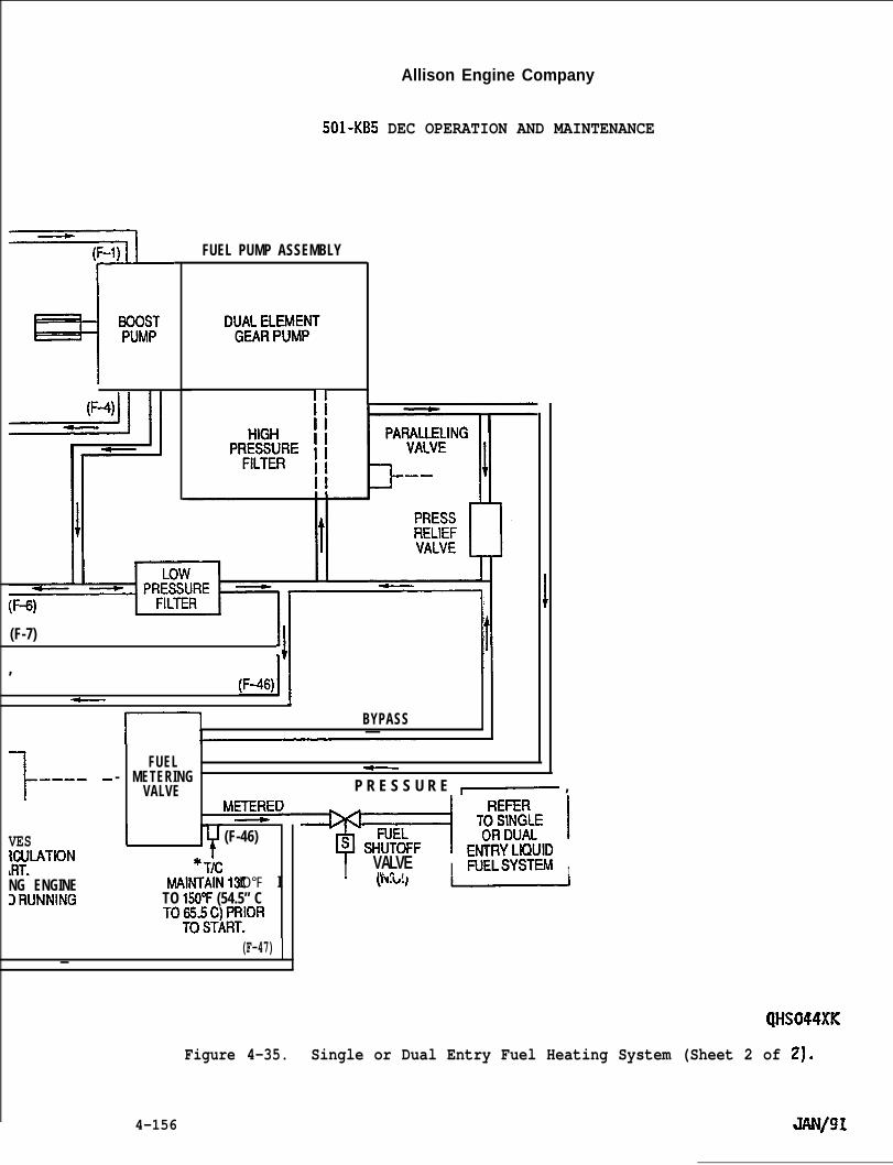
Allison Engine Company
501-KB5 DEC OPERATION AND MAINTENANCE
FUEL PUMP ASSEMBLY
DIJAJ:LflvlJvlpJT
II
(F-7)
,q 1!
(F-46)1~
BYPASS—
1-———— -VESKIJLATION~RT.NG ENGINEDRUNNING
FUEL- METERING
~
VALVE P R E S S U R E ,— ,METERE[
J-L(F-46)
+s
I. . . . . . . ..- -
I VALVE FUELSYSldMAINTAIN131.
,hl n , I
TO 150°F (54.5” CTO~6W~~P10R
.
IO°F I
(F-47) I—
(JHS044XK
Figure 4-35. Single or Dual Entry Fuel Heating System (Sheet 2 of 2).
4-156
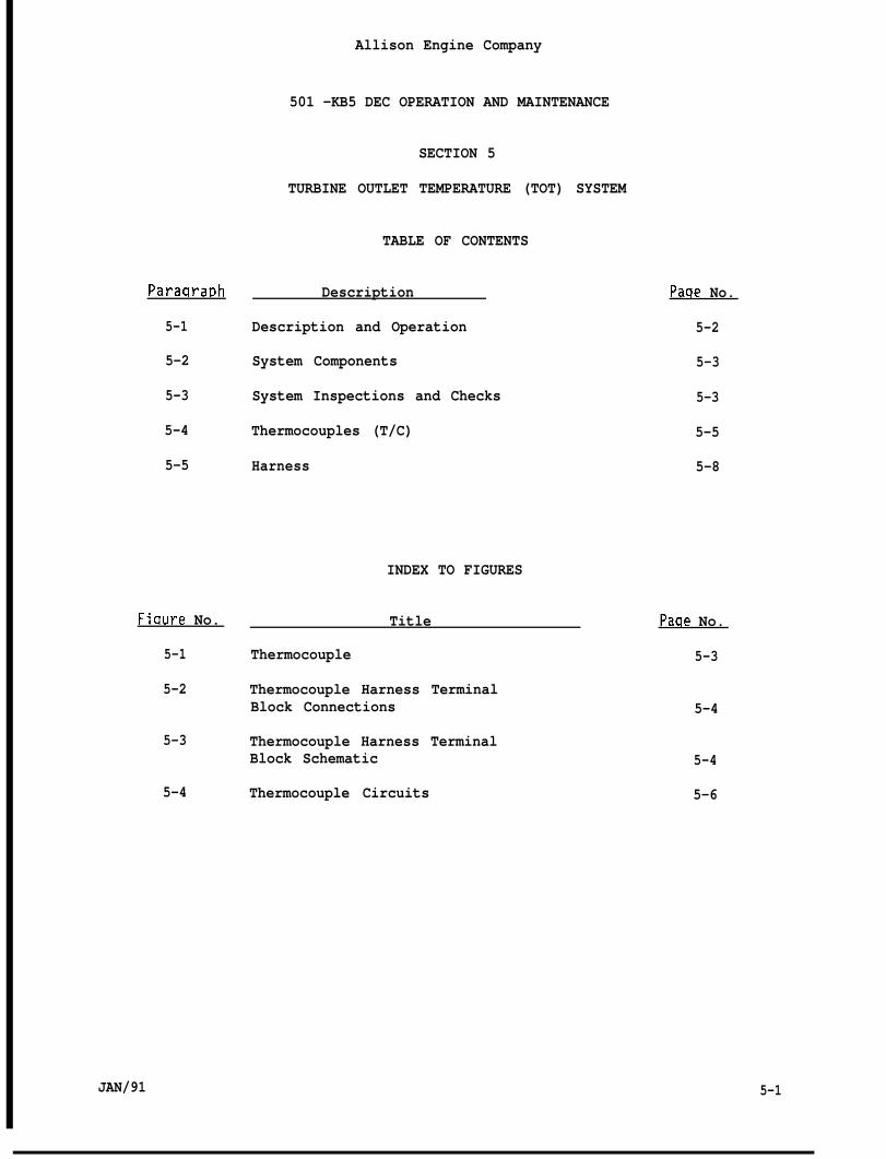
Allison Engine Company
501 -KB5 DEC OPERATION AND MAINTENANCE
SECTION 5
TURBINE OUTLET TEMPERATURE (TOT) SYSTEM
TABLE OF CONTENTS
ParaqraRh Description
5-1 Description and Operation
5-2 System Components
5-3 System Inspections and Checks
5-4 Thermocouples (T/C)
5-5 Harness
Paqe No.
5-2
5-3
5-3
5-5
5-8
INDEX TO FIGURES
Fiqure No. Title Paqe No.
5-1 Thermocouple 5-3
5-2 Thermocouple Harness TerminalBlock Connections 5-4
5-3 Thermocouple Harness TerminalBlock Schematic 5-4
5-4 Thermocouple Circuits 5-6
JAN/91 5-1
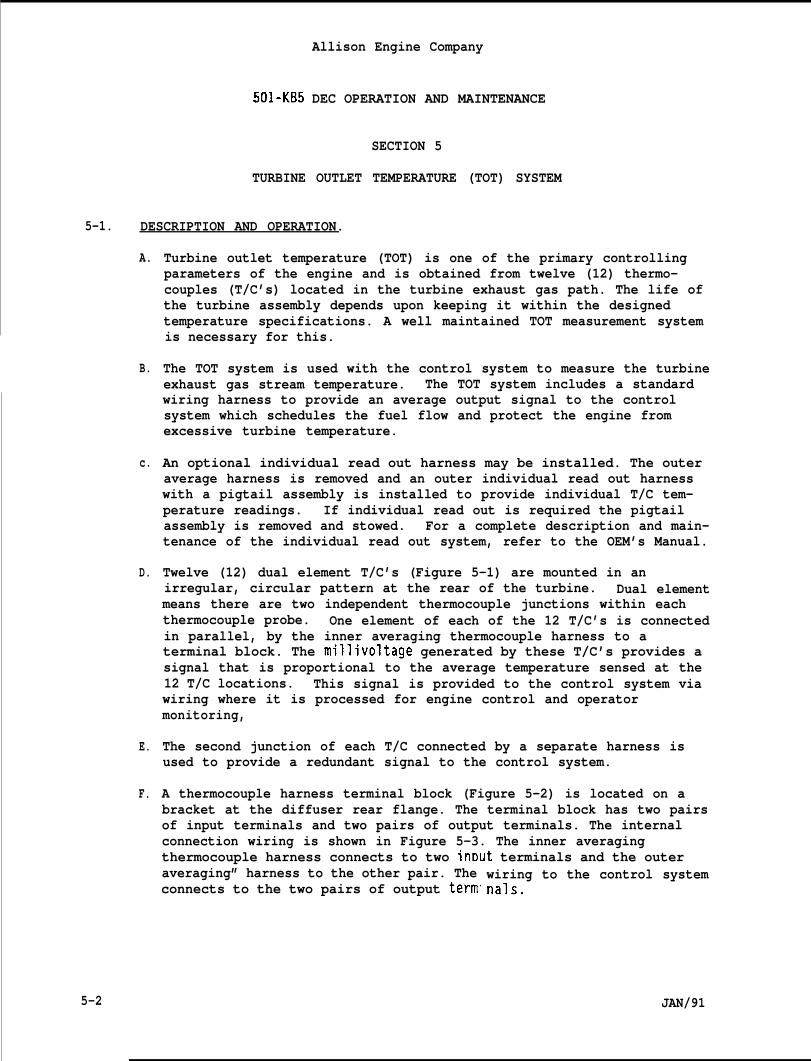
Allison Engine Company
501-KB5 DEC OPERATION AND MAINTENANCE
SECTION 5
TURBINE OUTLET TEMPERATURE (TOT) SYSTEM
5-1. DESCRIPTION AND OPERATION.
A.
B.
c.
D.
E.
F.
5-2
Turbine outlet temperature (TOT) is one of the primary controllingparameters of the engine and is obtained from twelve (12) thermo-couples (T/C’s) located in the turbine exhaust gas path. The life ofthe turbine assembly depends upon keeping it within the designedtemperature specifications. A well maintained TOT measurement systemis necessary for this.
The TOT system is used with the control system to measure the turbineexhaust gas stream temperature. The TOT system includes a standardwiring harness to provide an average output signal to the controlsystem which schedules the fuel flow and protect the engine fromexcessive turbine temperature.
An optional individual read out harness may be installed. The outeraverage harness is removed and an outer individual read out harnesswith a pigtail assembly is installed to provide individual T/C tem-perature readings. If individual read out is required the pigtailassembly is removed and stowed. For a complete description and main-tenance of the individual read out system, refer to the OEM’s Manual.
Twelve (12) dual element T/C’s (Figure 5-1) are mounted in anirregular, circular pattern at the rear of the turbine. Dual elementmeans there are two independent thermocouple junctions within eachthermocouple probe. One element of each of the 12 T/C’s is connectedin parallel, by the inner averaging thermocouple harness to aterminal block. The millivoltage generated by these T/C’s provides asignal that is proportional to the average temperature sensed at the12 T/C locations. This signal is provided to the control system viawiring where it is processed for engine control and operatormonitoring,
The second junction of each T/C connected by a separate harness isused to provide a redundant signal to the control system.
A thermocouple harness terminal block (Figure 5-2) is located on abracket at the diffuser rear flange. The terminal block has two pairsof input terminals and two pairs of output terminals. The internalconnection wiring is shown in Figure 5-3. The inner averagingthermocouple harness connects to two inr)ut terminals and the outeraveraging” harness to the other pair. Theconnects to the two pairs of output term
wiring to the control systemnals.
JAN/91
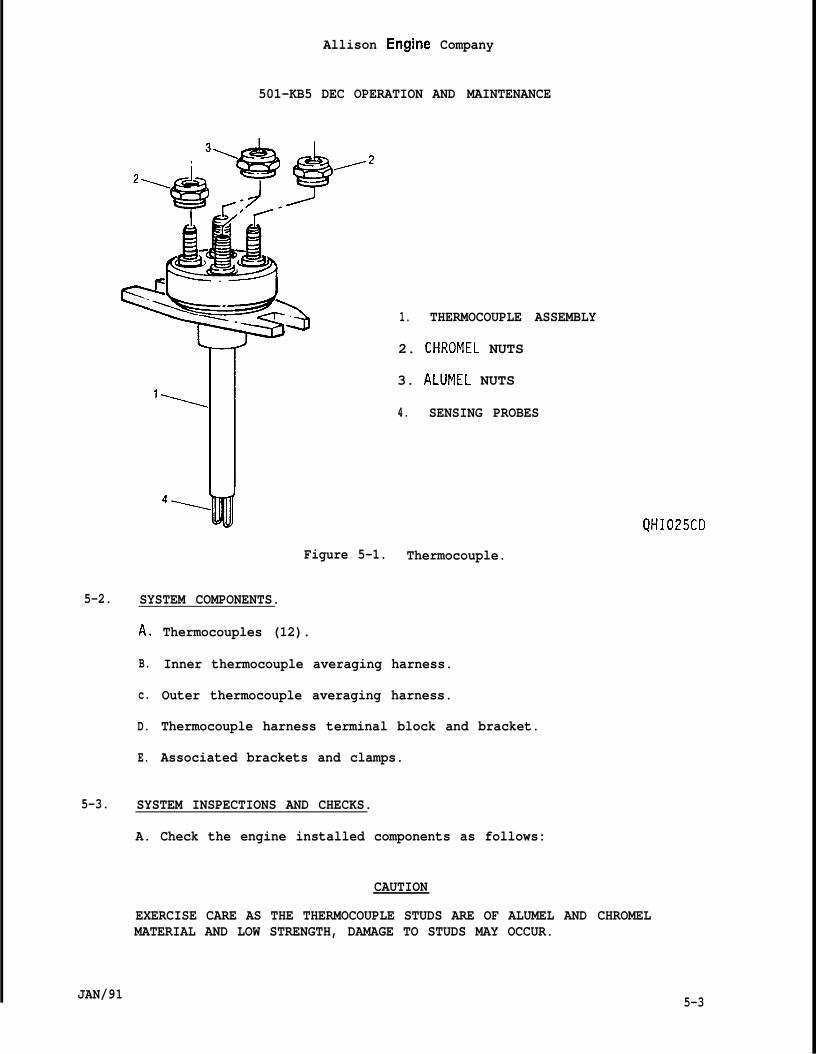
Allison Engine Company
501-KB5 DEC OPERATION AND MAINTENANCE
1. THERMOCOUPLE ASSEMBLY
2. CHROMEL NUTS
3. ALUMEL NUTS
4. SENSING PROBES
QHI025CD
Figure 5-1. Thermocouple.
5-2. SYSTEM COMPONENTS.
A.
B.
c.
D.
E.
Thermocouples (12).
Inner thermocouple averaging harness.
Outer thermocouple averaging harness.
Thermocouple harness terminal block and bracket.
Associated brackets and clamps.
5-3. SYSTEM INSPECTIONS AND CHECKS.
A. Check the engine installed components as follows:
CAUTION
EXERCISE CARE AS THE THERMOCOUPLE STUDS ARE OF ALUMEL AND CHROMELMATERIAL AND LOW STRENGTH, DAMAGE TO STUDS MAY OCCUR.
JAN/91 5-3
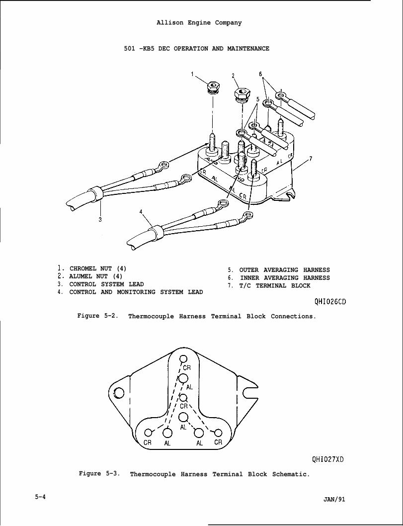
Allison Engine Company
501 -KB5 DEC OPERATION AND MAINTENANCE
1, 2 6.
;:3.4.
CHROMEL NUT (4) 5.ALUMEL NUT (4) 6.CONTROL SYSTEM LEAD 7.CONTROL AND MONITORING SYSTEM LEAD
OUTER AVERAGING HARNESSINNER AVERAGING HARNESST/C TERMINAL BLOCK
QHI026CD
Figure 5-2. Thermocouple Harness Terminal Block Connections.
QHI027XD
Figure 5-3. Thermocouple Harness Terminal Block Schematic.
5-4 JAN/91
Allison Engine Company
501-KB5 DEC OPERATION AND MAINTENANCE
1. Disconnect the control system leads (3 and 4, Figure 5-2) at thethermocouple harness terminal block. This isolates the check tothe engine system from the skid system (Ref. OEM’s Manual).
2. Use an ohmmeter and check the resistance from each chromel(smallest stud) to ground (shield).
3. If the resistance of each circuit to ground is at least 1000 ohms,the engine thermocouple system is satisfactory as far as groundleakage is concerned; however, some thermocouples could be open orhave missing or damaged probe tips.
4. If the resistance is less than 1000 ohms in either circuit:
a.
b.
c.
d.
B. Check
Remove all harness connections from the terminal block andcheck continuity of the terminal block.
If the resistance is less than 1000 ohms, replace the terminalblock.
Check each thermocouple resistance to ground. (Refer toParagraph 5-5, Step C.)
Check the harness resistance to ground. (Refer to Paragraph5-6, Step C.)
the resistance of the wiring from engine to control.
1. The specifications for these leads (cables) from the engine to thecontrol are two conductor (ISA type K positive and ISA type Knegative) with a minimum wire size of No. 17 AWG, insulated fromeach other, twisted, shielded, jacketed together and flexible.The cable must tolerate a 160”F (71”C) or greater heat inside theengine compartment.
2. The total (i.e. loop) circuit resistance of each lead -- short thealumel and chromel together at one end and measure resistancebetween them at the other end -- must not exceed 20 ohms. Thecircuit leakage resistance to ground minimum is 10,000 ohms foreach channel.
5-4. THERMOCOUPLES (T/C~.
A. Description.
1.
2.
JAN/91
The twelve (12) thermocouples (T/C’s) have bas tally alumel (AL)and chromel ‘(CR), ISA type K junctions. The T/C probes areexposed to the hot exhaust gasses.
The design of the T/C is such that it holds and protects thesensing probes while it controls and directs the hot exhaust
5-5
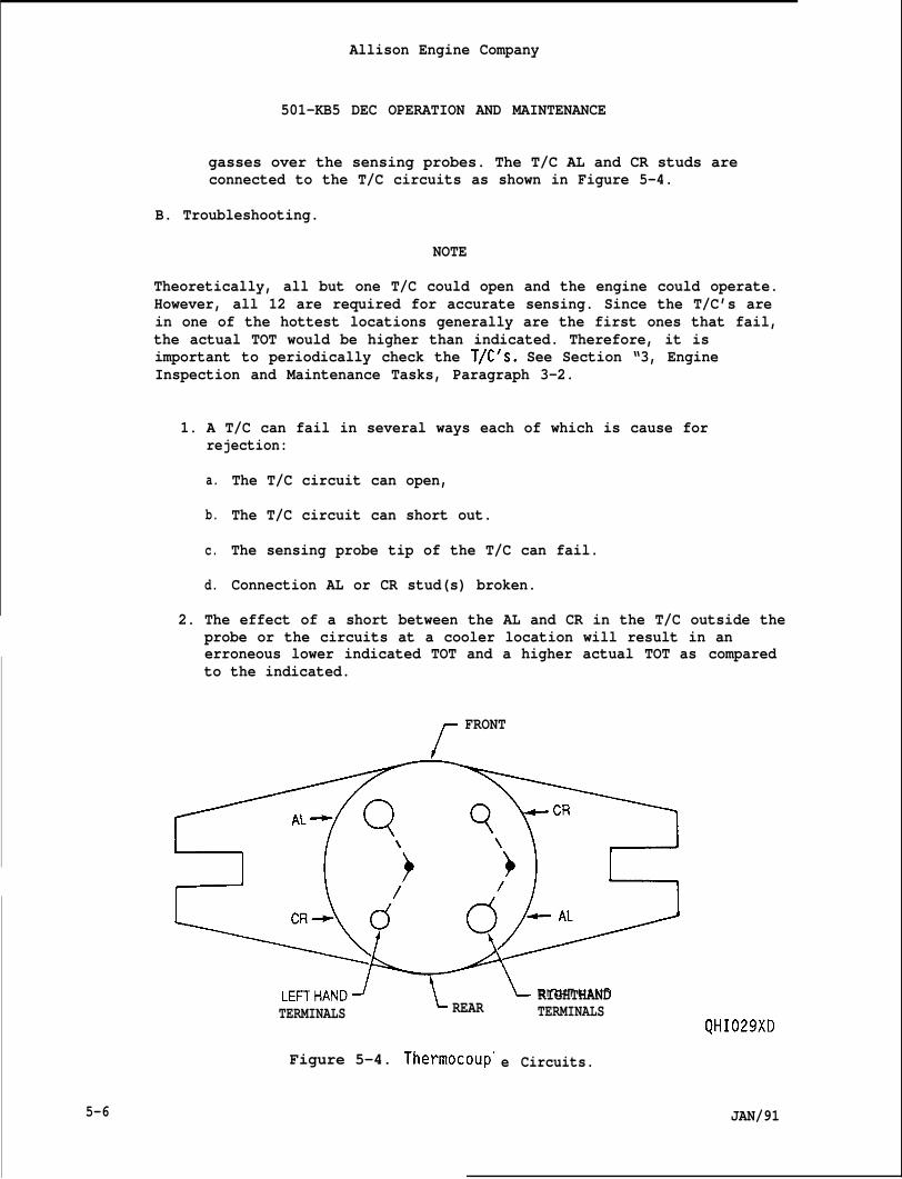
Allison Engine Company
501-KB5 DEC OPERATION AND MAINTENANCE
gasses over the sensing probes. The T/C AL and CR studs areconnected to the T/C circuits as shown in Figure 5-4.
B. Troubleshooting.
NOTE
Theoretically, all but one T/C could open and the engine could operate.However, all 12 are required for accurate sensing. Since the T/C’s arein one of the hottest locations generally are the first ones that fail,the actual TOT would be higher than indicated. Therefore, it isimportant to periodically check the T/C’s. See Section “3, EngineInspection and Maintenance Tasks, Paragraph 3-2.
1. A T/C can fail in several ways each of which is cause forrejection:
a.
b.
c.
d.
The T/C circuit can open,
The T/C circuit can short out.
The sensing probe tip of the T/C can fail.
Connection AL or CR stud(s) broken.
2. The effect of a short between the AL and CR in the T/C outside theprobe or the circuits at a cooler location will result in anerroneous lower indicated TOT and a higher actual TOT as comparedto the indicated.
f
FRONT
‘&(&y~RIGHTHANDTERMINALS
QHI029XD
LEFTHAND4TERMINALS L REAR
Figure 5-4. Thermocoup” e Circuits.
5-6 JAN/91
Allison Engine Company
501-KB5 DEC OPERATION AND MAINTENANCE
3. Tests indicate that up to 6°F (3.33”C) loss in indicated CALTITcan be expected for every T/C circuit that opens and a 13°F(7.2”C) loss in indicated CALTIT mayin the T/C sensing probe tip.
4. Periodically removing and carefully “vidually is the most direct approachconditions. Keeping good records andfrom them is important.
CAUTION
be expected for every failure
nspecting the T/C’s indi-to troubleshooting theseanalyzing engine performance
WITH ANY SUBSEQUENT SPEED OR POWER INCREASE WITH NO INCREASE ININDICATED CALTIT, CHECK FORAN OVERLY HOT TURBINE AND LOOK FOR TROUBLEIN THE TOT AND CONTROL SYSTEMS. THE CONTROL SYSTEM COMPUTES CALTIT.
C. Removal.
CAUTION
EXERCISE CARE AS THE THERMOCOUPLE STUDS ARE OF A LOW STRENGTH ALUMELAND CHROMEL MATERIAL. DAMAGE TO STUDS MAY OCCUR.
1. Disconnect the T/C harness from the individual T/C.
2. Remove the T/C mounting nuts, remove the T/C and the gasket.Discard gasket.
D. Inspection of Removed Thermocouples (T/C).
1. Perform the electrical check if not already accomplished. Rejectthe T/C if the resistance between individual T/C circuits or theresistance from either circuit to the case is less than 100,000ohms. Reject if the resistance of either circuit is 5 ohms orless.
2. Inspect for the following conditions each of which is cause forrejection:
a. Probe body is badly bent or shows evidence of a burnedcondition.
b. Visual evidence of missing (eroded) aluminum oxide insulatingmaterial from around the wires up in the wire shield.
c. Burned or missing T/C junction (should be detectable byelectrical check).
d. Broken AL or CR stud(s).
JAN/91 5-7
Allison Engine company
501 -KB5 DEC OPERATION AND MAINTENANCE
E. Installation.
1. Instal
2. Instal
3. Instalin. (4
gasket on each T/C.
T/C in support.
nuts on mounting support studs and torque nuts to 40-60 lb5-6.8 N-m).
4. Install harness terminals on respective CR and AL studs.
5. Install terminal nuts on respective CR and AL studs. Torque nutsto 18-22 lb in. (2.0-2.8 N-m).
5-5. HARNESS.
A. Description.
1. Terminal connectors for the T/C’s, 12 pair of chromel (CR) andalumel (AL) (CR and AL terminals are of different hole size withthe CR being the smaller).
2. Internal Type K wiring to connect the 12 inputs in parallel thusproviding an average output signal.
3. An output connection pair of CR and AL terminals.
4. The wires are sheathed in a wrapping shield with inconel wirebraid on the exterior.
B. Removal.
CAUTION
EXERCISE CARE AS THE T/C STUDS ARE OF A LOW STRENGTH ALUMEL AND CHROMELMATERIAL. DAMAGE TO STUDS MAY OCCUR.
1. Disconnect the harness from the T/C terminal block (located on theengine at the diffuser aft flange) and from individual T/C’s studsper Paragraph 5-4, Step C. (Ref. Figures 5-1 and 5-2).
2. Remove or loosen the clamps holding the harness.
C. Inspection and Checks.
1. Check for outer braid for evidence of wear. Replace if areas areworn through.
2. Check for deteriorated or missing insulation at the breakouts(near connections to T/C studs and to terminal block studs).
5-8 JAN/91
JAN/91
Allison Engine Company
501-KB5 DEC OPERATION AND MAINTENANCE
3. Perform a resistance check. With all leads disconnected from theT/C’s and the terminal block, the resistance of any alumel circuitmeasured from the T/C connection to the terminal block connectionshould be between 0.64 and 0.71 ohms. The resistance of any CRcircuit measured from the T/C connection to the terminal blockconnection should be between 1.60 and 1.77 ohms. The resistancevalues are for 70”F (17.7”C). If the resistance values are outsidethese limits, the harness must be replaced.
D. Installation.
1. Install clamps.
2. Connect harness to T/C terminal block and T/C’s studs perParagraph 5-4, Step E-5 (Ref. Figures 5-1 and 5-2).
5-9
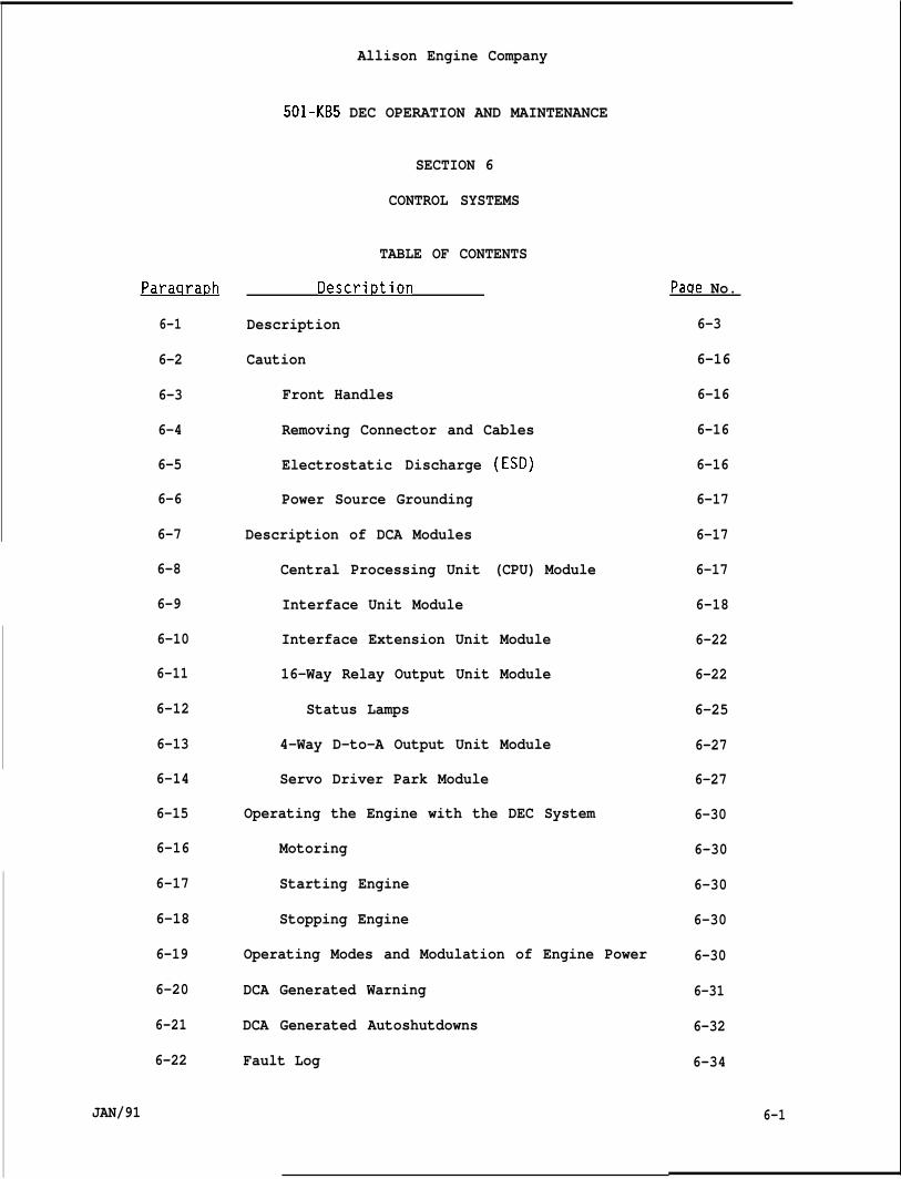
Paraqrar)h
6-1
6-2
6-3
6-4
6-5
6-6
6-7
6-8
6-9
6-10
6-11
6-12
6-13
6-14
6-15
6-16
6-17
6-18
6-19
6-20
6-21
6-22
JAN/91
Allison Engine Company
501-KB5 DEC OPERATION AND MAINTENANCE
SECTION 6
CONTROL SYSTEMS
TABLE OF CONTENTS
Descri~tion
Description
Caution
Front Handles
Removing Connector and Cables
Electrostatic Discharge
Power Source Grounding
Description of DCA Modules
Central Processing Unit
Interface Unit Module
(ESD)
(CPU) Module
Interface Extension Unit Module
16-Way Relay Output Unit Module
Status Lamps
4-Way D-to-A Output Unit Module
Servo Driver Park Module
Operating the Engine with the DEC System
Motoring
Starting Engine
Stopping Engine
Operating Modes and Modulation of Engine Power
DCA Generated Warning
DCA Generated Autoshutdowns
Fault Log
Paqe No.
6-3
6-16
6-16
6-16
6-16
6-17
6-17
6-17
6-18
6-22
6-22
6-25
6-27
6-27
6-30
6-30
6-30
6-30
6-30
6-31
6-32
6-34
6-1
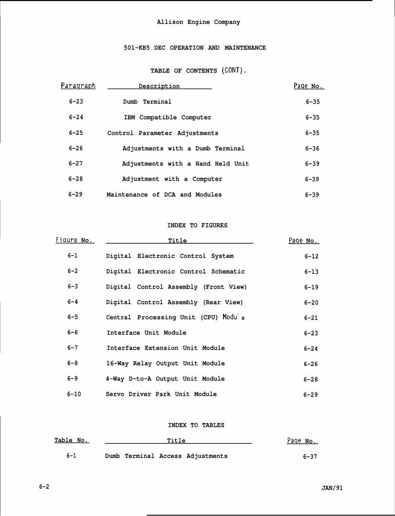
Paraqrat)h
6-23
6-24
6-25
6-26
6-27
6-28
6-29
Fiqure No.
6-1
6-2
6-3
6-4
6-5
6-6
6-7
6-8
6-9
6-10
Table No.
6-1
Allison Engine Company
501-KB5 DEC OPERATION AND MAINTENANCE
TABLE OF CONTENTS (CONT).
Description
Dumb Terminal
IBM Compatible Computer
Control Parameter Adjustments
Adjustments with a Dumb Terminal
Adjustments with a Hand Held Unit
Adjustment with a Computer
Maintenance of DCA and Modules
INDEX TO FIGURES
Title
Digital
Digital
Digital
Digital
Central
Electronic Control System
Electronic Control Schematic
Control Assembly (Front View)
Control Assembly (Rear View)
Processing Unit (CPU) Modu-
Interface Unit Module
Interface Extension Unit Module
16-Way Relay Output Unit Module
4-Way D-to-A Output Unit Module
Servo Driver Park Unit Module
INDEX TO TABLES
e
Title
Dumb Terminal Access Adjustments
Paqe No.
6-35
6-35
6-35
6-36
6-39
6-39
6-39
Paqe No.
6-12
6-13
6-19
6-20
6-21
6-23
6-24
6-26
6-28
6-29
Paqe No.
6-37
6-2 JAN/91
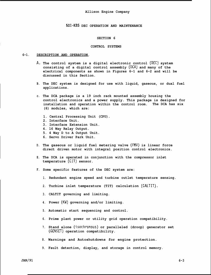
Allison Engine Company
501-KB5 DEC OPERATION AND MAINTENANCE
I
6-1.
SECTION 6
CONTROL SYSTEMS
DESCRIPTION AND OPERATION.
A.
B.
c.
D.
E.
F.
JAN/91
The control system is a digital electronic control (DEC) systemconsisting of a digital control assembly (DCA) and many of theelectrical components as shown in Figures 6-1 and 6-2 and will bediscussed in this Section.
The DEC system is designed for use with liquid, gaseous, or dual fuelapplications.
The DCA package is a 19 inch rack mounted assembly housing thecontrol electronics and a power supply. This package is designed forinstallation and operation within the control room. The DCA has six(6) modules, which are:
1. Central Processing Unit (CPU).2. Interface Unit.3. Interface Extension Unit.4. 16 Way Relay Output.5. 4 Way D to A Output Unit.6. Servo Driver Park Unit.
The gaseous or liquid fuel metering valve (FMV) is linear forcedirect driven motor with integral position control electronics.
The DCA is operated in conjunction with the compressor inlettemperature (CIT) sensor.
Some specific features of the DEC system are:
1.
2.
3.
4.
5.
6.
7.
8.
9.
Redundant engine speed and turbine outlet temperature sensing.
Turbine inlet temperature (TIT) calculation (CALTIT).
CALTIT governing and limiting.
Power (KW) governing and/or limiting.
Automatic start sequencing and control.
Prime plant power or utility grid operation compatibility.
Stand alone (isochronous) or paralleled (droop) generator set(GENSET) operation compatibility.
Warnings and Autoshutdowns for engine protection.
Fault detection, display, and storage in control memory.
6-3
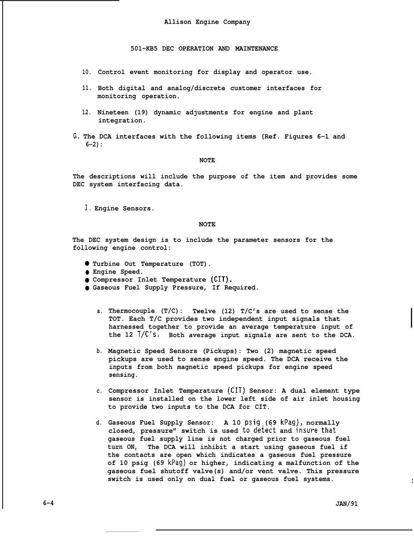
10.
11.
12.
Allison Engine Company
501-KB5 DEC OPERATION AND MAINTENANCE
Control event monitoring for display and operator use.
Both digital and analog/discrete customer interfaces formonitoring operation.
Nineteen (19) dynamic adjustments for engine and plantintegration.
G. The DCA interfaces with the following items (Ref. Figures 6-1 and6-2):
NOTE
The descriptions will include the purpose of the item and provides someDEC system interfacing data.
1, Engine Sensors.
NOTE
The DEC system design is to include the parameter sensors for thefollowing engine control:
●
●
●
●
Turbine Out Temperature (TOT).Engine Speed.Compressor Inlet Temperature (CIT).Gaseous Fuel Supply Pressure, If Required.
a.
b.
c.
d.
Thermocouple (T/C): Twelve (12) T/C’s are used to sense theTOT. Each T/C provides two independent input signals thatharnessed together to provide an average temperature input ofthe 12 T/C’s. Both average input signals are sent to the DCA.
Magnetic Speed Sensors (Pickups): Two (2) magnetic speedpickups are used to sense engine speed. The DCA receive theinputs from both magnetic speed pickups for engine speedsensing.
Compressor Inlet Temperature (CIT) Sensor: A dual element typesensor is installed on the lower left side of air inlet housingto provide two inputs to the DCA for CIT.
Gaseous Fuel Supply Sensor: A 10 psig (69 kPag), normallyclosed, pressure” switch is used to”de~ect and insure that-gaseous fuel supply line is not charged prior to gaseous fuelturn ON, The DCA will inhibit a start using gaseous fuel ifthe contacts are open which indicates a gaseous fuel pressureof 10 psig (69 kPag) or higher, indicating a malfunction of thegaseous fuel shutoff valve(s) and/or vent valve. This pressureswitch is used only on dual fuel or gaseous fuel systems. I
6-4 JAN/91
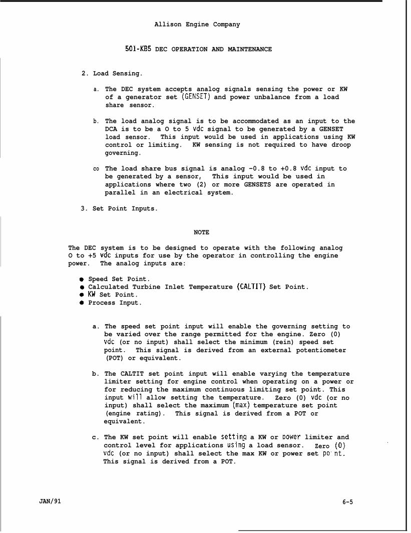
Allison Engine Company
501-KB5 DEC OPERATION AND MAINTENANCE
2. Load Sensing.
a.
b.
co
The DEC system accepts analog signals sensing the power or KWof a generator set (GENSET) and power unbalance from a loadshare sensor.
The load analog signal is to be accommodated as an input to theDCA is to be a O to 5 vdc signal to be generated by a GENSETload sensor. This input would be used in applications using KWcontrol or limiting. KW sensing is not required to have droopgoverning.
The load share bus signal is analog -0.8 to +0.8 vdc input tobe generated by a sensor, This input would be used inapplications where two (2) or more GENSETS are operated inparallel in an electrical system.
3. Set Point Inputs.
NOTE
The DEC system is to be designed to operate with the following analogO to +5 vdc inputs for use by the operator in controlling the enginepower. The analog inputs are:
Speed Set Point.Calculated Turbine Inlet Temperature (CALTIT) Set Point.KW Set Point.Process Input.
a. The speed set point input will enable the governing setting tobe varied over the range permitted for the engine. Zero (0)vdc (or no input) shall select the minimum (rein) speed setpoint. This signal is derived from an external potentiometer(POT) or equivalent.
b. The CALTIT set point input will enable varying the temperaturelimiter setting for engine control when operating on a power orfor reducing the maximum continuous limiting set point. Thisinput will allow setting the temperature. Zero (0) vdc (or noinput) shall select the maximum (max) temperature set point(engine rating). This signal is derived from a POT orequivalent.
c. The KW set point will enable settinq a KW or Dower limiter andcontrol level for applications usin~ a load sensor. Zerovdc (or no input) shall select the max KW or power set poThis signal is derived from a POT.
JAN/91 6-5
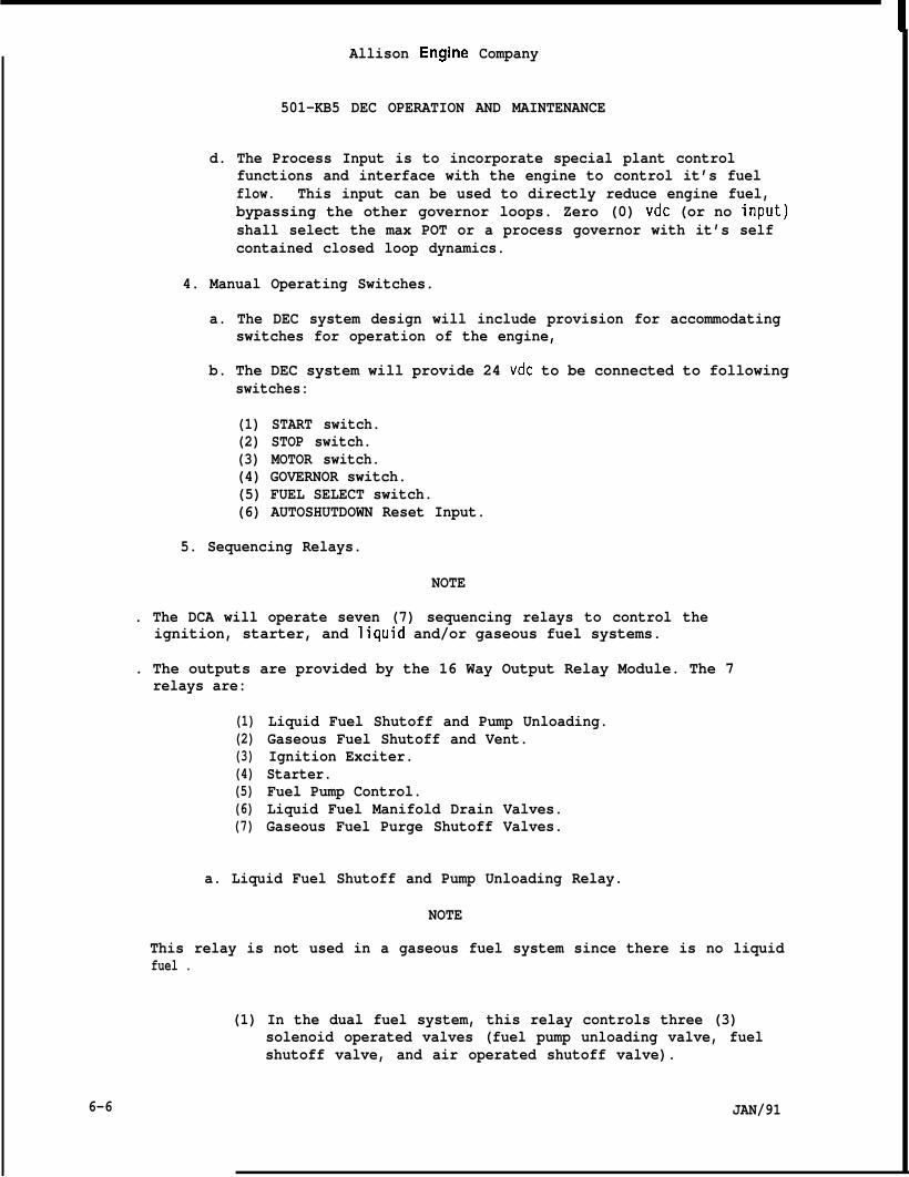
Allison Engine Company
501-KB5 DEC OPERATION AND MAINTENANCE
d. The Process Input is to incorporate special plant controlfunctions and interface with the engine to control it’s fuelflow. This input can be used to directly reduce engine fuel,bypassing the other governor loops. Zero (0) vdc (or no input)shall select the max POT or a process governor with it’s selfcontained closed loop dynamics.
4. Manual Operating Switches.
a. The DEC system design will include provision for accommodatingswitches for operation of the engine,
b. The DEC system will provide 24 vdc to be connected to followingswitches:
(1) START switch.(2) STOP switch.(3) MOTOR switch.(4) GOVERNOR switch.(5) FUEL SELECT switch.(6) AUTOSHUTDOWN Reset Input.
5. Sequencing Relays.
NOTE
. The DCA will operate seven (7) sequencing relays to control theignition, starter, and liquid and/or gaseous fuel systems.
. The outputs are provided by the 16 Way Output Relay Module. The 7relays are:
(1)(2)(3)(4)(5)(6)(7)
Liquid Fuel Shutoff and Pump Unloading.Gaseous Fuel Shutoff and Vent.Ignition Exciter.Starter.Fuel Pump Control.Liquid Fuel Manifold Drain Valves.Gaseous Fuel Purge Shutoff Valves.
a. Liquid Fuel Shutoff and Pump Unloading Relay.
NOTE
This relay is not used in a gaseous fuel system since there is no liquidfuel .
(1) In the dual fuel system, this relay controls three (3)solenoid operated valves (fuel pump unloading valve, fuelshutoff valve, and air operated shutoff valve).
6-6 JAN/91
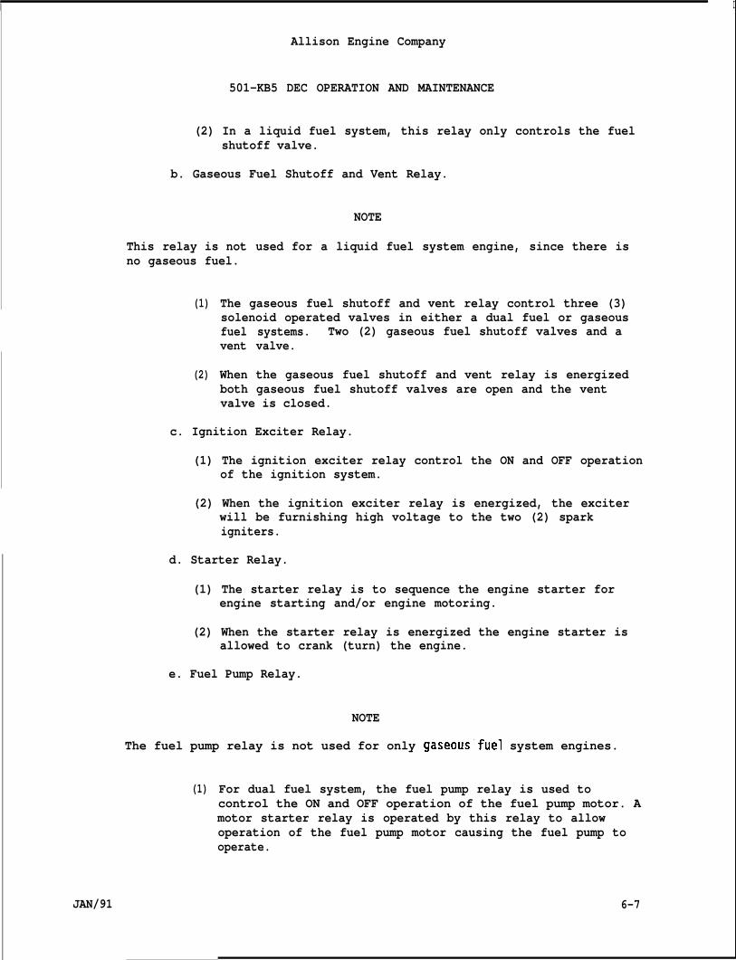
I
Allison Engine Company
501-KB5 DEC OPERATION AND MAINTENANCE
(2) In a liquid fuel system, this relay only controls the fuelshutoff valve.
b. Gaseous Fuel Shutoff and Vent Relay.
NOTE
This relay is not used for a liquid fuel system engine, since there isno gaseous fuel.
(1)
(2)
The gaseous fuel shutoff and vent relay control three (3)solenoid operated valves in either a dual fuel or gaseousfuel systems. Two (2) gaseous fuel shutoff valves and avent valve.
When the gaseous fuel shutoff and vent relay is energizedboth gaseous fuel shutoff valves are open and the ventvalve is closed.
c. Ignition Exciter Relay.
(1) The ignition exciter relay control the ON and OFF operationof the ignition system.
(2) When the ignition exciter relay is energized, the exciterwill be furnishing high voltage to the two (2) sparkigniters.
d. Starter Relay.
(1) The starter relay is to sequence the engine starter forengine starting and/or engine motoring.
(2) When the starter relay is energized the engine starter isallowed to crank (turn) the engine.
e. Fuel Pump Relay.
NOTE
The fuel pump relay is not used for only gaseous”fuel system engines.
(1)
JAN/91
For dual fuel system, the fuel pump relay is used tocontrol the ON and OFF operation of the fuel pump motor. Amotor starter relay is operated by this relay to allowoperation of the fuel pump motor causing the fuel pump tooperate.
6-7
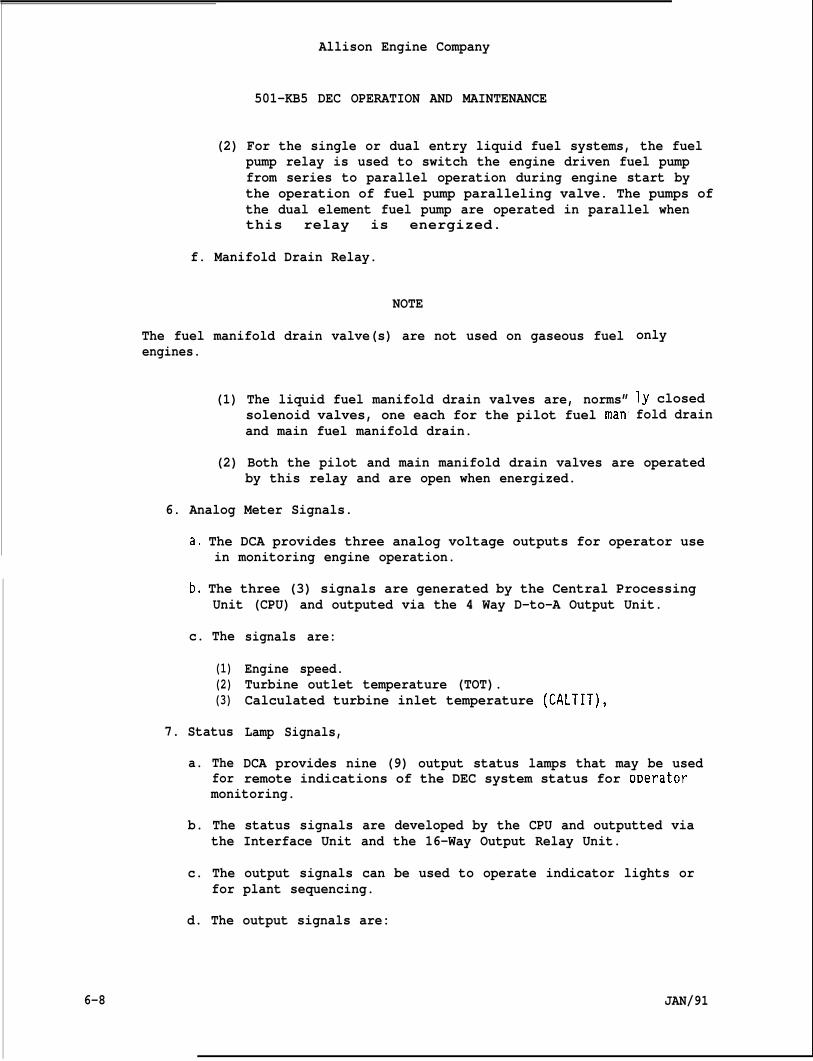
Allison Engine Company
501-KB5 DEC OPERATION AND MAINTENANCE
(2) For the single or dual entry liquid fuel systems, the fuelpump relay is used to switch the engine driven fuel pumpfrom series to parallel operation during engine start bythe operation of fuel pump paralleling valve. The pumps ofthe dual element fuel pump are operated in parallel whenthis relay is energized.
f. Manifold Drain Relay.
NOTE
The fuel manifold drain valve(s) are not used on gaseous fuelengines.
(1) The liquid fuel manifold drain valves are, norms”solenoid valves, one each for the pilot fuel manand main fuel manifold drain.
only
ly closedfold drain
(2) Both the pilot and main manifold drain valves are operatedby this relay and are open when energized.
6. Analog Meter Signals.
a, The DCA provides three analog voltage outputs for operator usein monitoring engine operation.
b, The three (3) signals are generated by the Central ProcessingUnit (CPU) and outputed via the 4 Way D-to-A Output Unit.
c. The
(1)(2)(3)
7. Status
a. Thefor
signals are:
Engine speed.Turbine outlet temperature (TOT).Calculated turbine inlet temperature (CALTIT),
Lamp Signals,
DCA provides nine (9) output status lamps that may be usedremote indications of the DEC system status for oDerator
monitoring.
b. The status signals are developed by the CPU and outputted viathe Interface Unit and the 16-Way Output Relay Unit.
c. The output signals can be used to operate indicator lights orfor plant sequencing.
d. The output signals are:
6-8 JAN/91
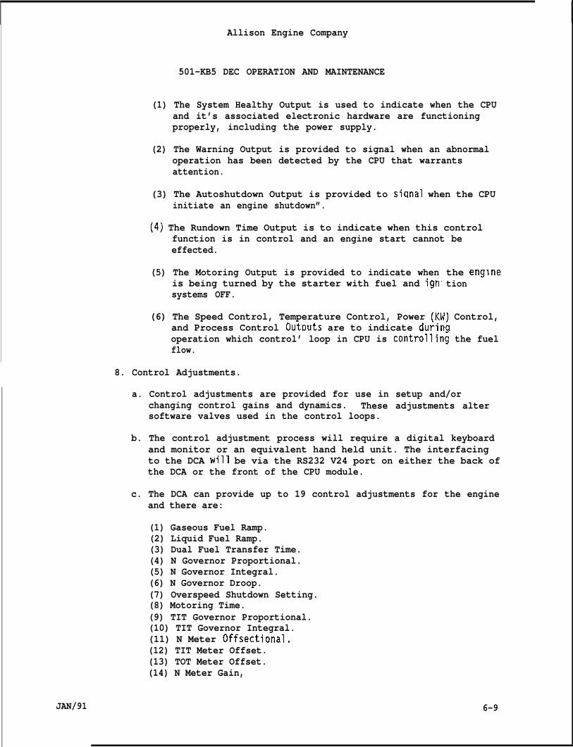
IAllison Engine Company
501-KB5 DEC OPERATION AND MAINTENANCE
(1) The System Healthy Output is used to indicate when the CPUand it’s associated electronic hardware are functioningproperly, including the power supply.
(2) The Warning Output is provided to signal when an abnormaloperation has been detected by the CPU that warrantsattention.
(3) The Autoshutdown Output is provided to siqnal when the CPUinitiate an engine shutdown”.
(4) The Rundown Time Output is to indicate when this controlfunction is in control and an engine start cannot beeffected.
(5) The Motoring Output is provided to indicate whenis being turned by the starter with fuel and ignsystems OFF.
the engnetion
(6) The Speed Control, Temperature Control, Power (KW) Control,and Process Control OutDuts are to indicate durinaoperation which control’ loop in CPU is controllin~ the fuelflow.
8. Control Adjustments.
a. Control adjustments are provided for use in setup and/orchanging control gains and dynamics. These adjustments altersoftware valves used in the control loops.
b. The control adjustment process will require a digital keyboardand monitor or an equivalent hand held unit. The interfacingto the DCA will be via the RS232 V24 port on either the back ofthe DCA or the front of the CPU module.
c. The DCA can provide up to 19 control adjustments for the engineand there are:
(1) Gaseous Fuel Ramp.(2) Liquid Fuel Ramp.(3) Dual Fuel Transfer Time.(4) N Governor Proportional.(5) N Governor Integral.(6) N Governor Droop.(7) Overspeed Shutdown Setting.(8) Motoring Time.(9) TIT Governor Proportional.(10) TIT Governor Integral.(11) N Meter Offsectional.(12) TIT Meter Offset.(13) TOT Meter Offset.(14) N Meter Gain,
JAN/91 6-9
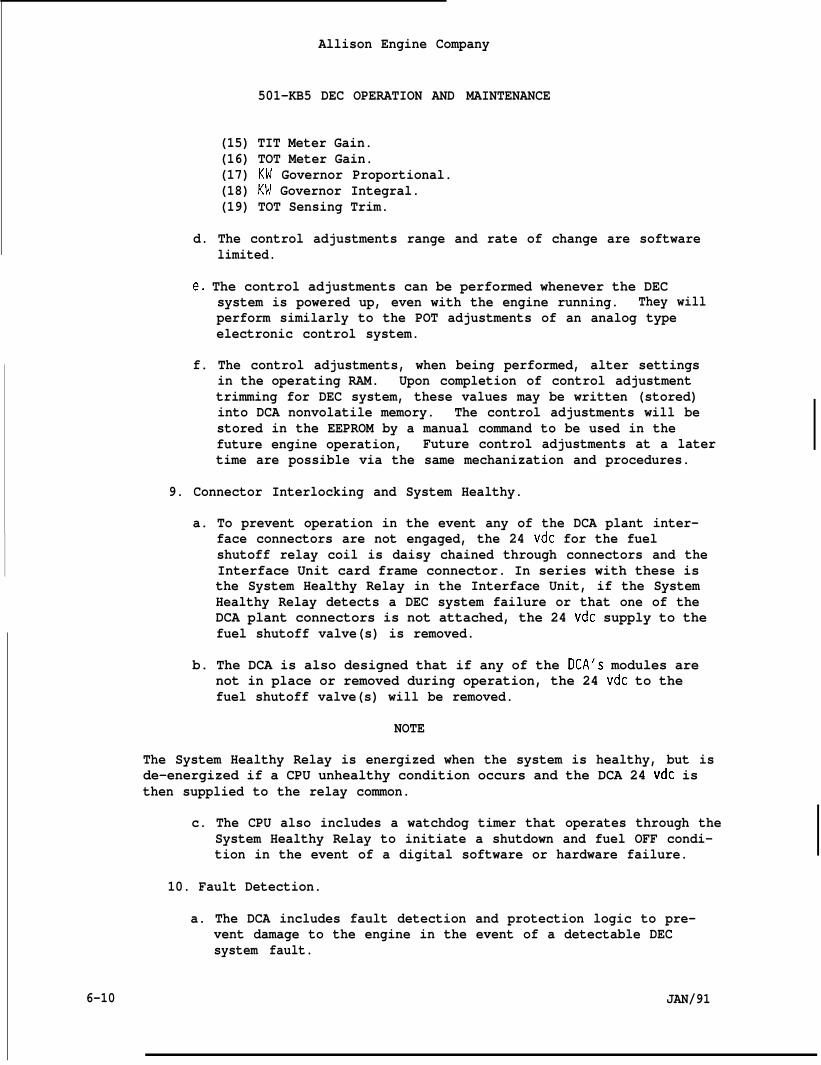
Allison Engine Company
501-KB5 DEC OPERATION AND MAINTENANCE
(15) TIT Meter Gain.(16) TOT Meter Gain.(17) KW Governor Proportional.(18) KW Governor Integral.(19) TOT Sensing Trim.
d. The control adjustments range and rate of change are softwarelimited.
e, The control adjustments can be performed whenever the DECsystem is powered up, even with the engine running. They willperform similarly to the POT adjustments of an analog typeelectronic control system.
f. The control adjustments, when being performed, alter settingsin the operating RAM. Upon completion of control adjustmenttrimming for DEC system, these values may be written (stored)into DCA nonvolatile memory. The control adjustments will bestored in the EEPROM by a manual command to be used in thefuture engine operation, Future control adjustments at a latertime are possible via the same mechanization and procedures.
9. Connector Interlocking and System Healthy.
a. To prevent operation in the event any of the DCA plant inter-face connectors are not engaged, the 24 vdc for the fuelshutoff relay coil is daisy chained through connectors and theInterface Unit card frame connector. In series with these isthe System Healthy Relay in the Interface Unit, if the SystemHealthy Relay detects a DEC system failure or that one of theDCA plant connectors is not attached, the 24 vdc supply to thefuel shutoff valve(s) is removed.
b. The DCA is also designed that if any of the DCA’S modules arenot in place or removed during operation, the 24 vdc to thefuel shutoff valve(s) will be removed.
NOTE
The System Healthy Relay is energized when the system is healthy, but isde-energized if a CPU unhealthy condition occurs and the DCA 24 vdc isthen supplied to the relay common.
c. The CPU also includes a watchdog timer that operates through theSystem Healthy Relay to initiate a shutdown and fuel OFF condi-tion in the event of a digital software or hardware failure.
10. Fault Detection.
a. The DCA includes fault detection and protection logic to pre-vent damage to the engine in the event of a detectable DECsystem fault.
6-10 JAN/91
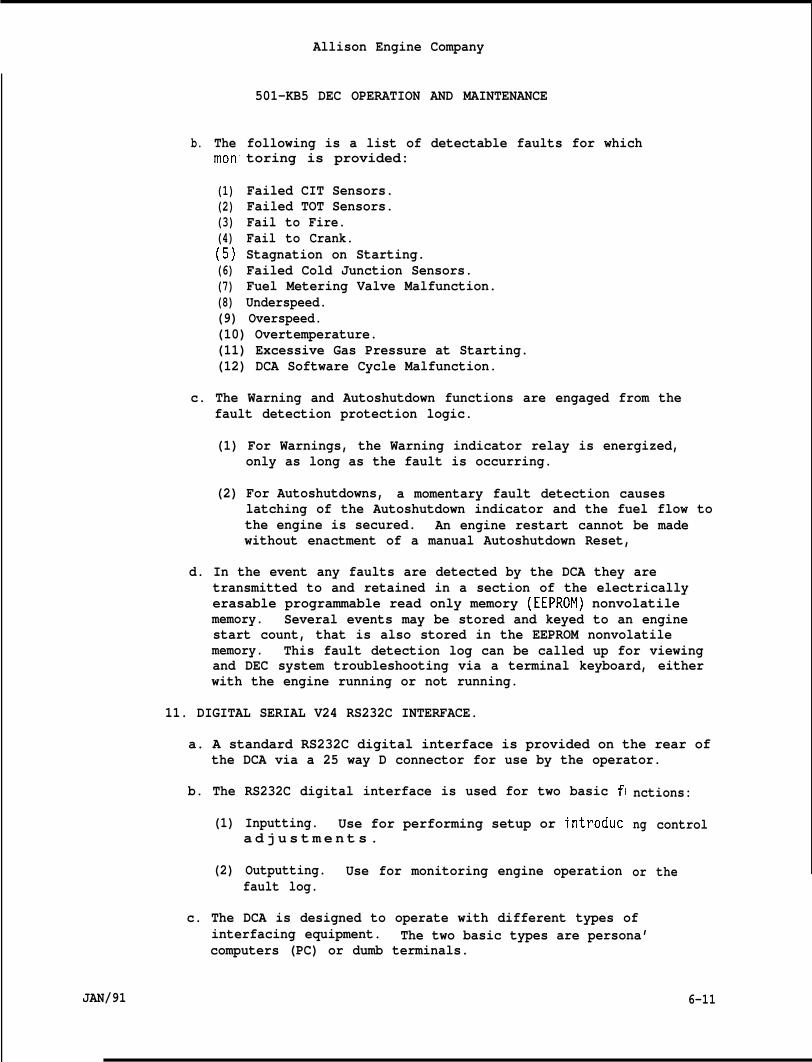
Allison Engine Company
501-KB5 DEC OPERATION AND MAINTENANCE
b. Themon
(1)(2)(3)(4)(5)(6)(7)(8)
following is a list of detectable faults for whichtoring is provided:
Failed CIT Sensors.Failed TOT Sensors.Fail to Fire.Fail to Crank.Stagnation on Starting.Failed Cold Junction Sensors.Fuel Metering Valve Malfunction.Underspeed.
(9) Overspeed.(10) Overtemperature.(11) Excessive Gas Pressure at Starting.(12) DCA Software Cycle Malfunction.
c. The Warning and Autoshutdown functions are engaged from thefault detection protection logic.
(1) For Warnings, the Warning indicator relay is energized,only as long as the fault is occurring.
(2) For Autoshutdowns, a momentary fault detection causeslatching of the Autoshutdown indicator and the fuel flow tothe engine is secured. An engine restart cannot be madewithout enactment of a manual Autoshutdown Reset,
d. In the event any faults are detected by the DCA they aretransmitted to and retained in a section of the electricallyerasable programmable read only memory (EEPROM) nonvolatilememory. Several events may be stored and keyed to an enginestart count, that is also stored in the EEPROM nonvolatilememory. This fault detection log can be called up for viewingand DEC system troubleshooting via a terminal keyboard, eitherwith the engine running or not running.
11. DIGITAL SERIAL V24 RS232C INTERFACE.
a. A standard RS232C digital interface is provided on the rear ofthe DCA via a 25 way D connector for use by the operator.
b. The RS232C digital interface is used for two basic f{
(1) Inputting. Use for performing setup or introduca d j u s t m e n t s .
(2) Outputting. Use for monitoring engine operationfault log.
nctions:
ng
or
c. The DCA is designed to operate with different types ofinterfacing equipment. The two basic types are persona’computers (PC) or dumb terminals.
JAN/91
control
the
6-11
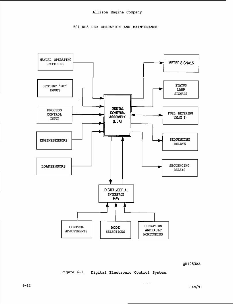
Allison Engine Company
501-KB5 DEC OPERATION AND MAINTENANCE
MANUAL OPERATINGSWITCHES
SETPOINT “POT” STATUSINPUTS LAMP
‘ z~“: -
SIGNALS
PROCESS DIGITALCONTROL CONTROL FUEL METERINGINPUT ASSEMBLY VALVE(S)
(DCA)
ENGINESENSORS SEQUENCINGRELAYS
LOADSENSORS D SEQUENCINGRELAYS
v IDIGITAlfSERIALINTERFACE
Fwv
I
CONTROL MODE OPERATIONADJUSTMENTS SELECTIONS ANDFAULT
MONITORING
QHI053AA
Figure 6-1. Digital Electronic Control System.
6-12 ----JAN/91
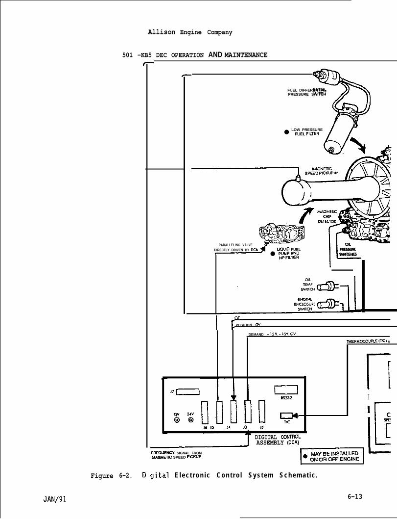
Figure
Allison Engine Company
501 -KB5 DEC OPERATION AND MAINTENANCE
6-2.
%
FUEL DIFFERENTIALPRESSURE SWITCH
LOW PRESSURE● F~ELFILTER n
—-----q
PARALLELING VALVEDIRECTLY DRIVEN BY DCA LIC2UID FUEL
IL
PRESSURE● P#;L&: WITCHES
11CIT
POSITION. Ov
DEMAND .15 V-15VOV
THERMIXOUPLE ~~) s
J7 ~1
u: If
J6 J5 Ji J3 JzDIGITAL CONTROt-ASSEMBLY (DGA) L
FWUSNCY SIGNAL FROMMAGNmC SPEED PBXUp
~–
gital
I v
E l e c t r o n i c C o n t r o l S y s t e m S c h e m a t i c .
nI
6-13
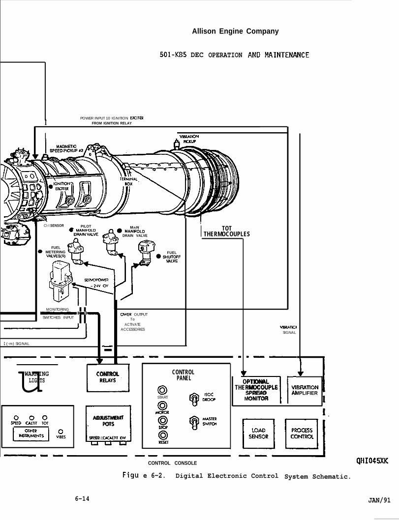
Allison Engine Company
501-KB5 DEC OPERATION
. POWER INPUT 10 IGNITION EKITERI FROM IGNITION RELAY
I VIMATIC+4
Cl-l SENSOR PILOT● MANIFOLO
MAIN● MANIFOLO
DRAIN VALVE , DRAIN VALVE
~Q
-cd _.
FUEL(
● C
) METERING, Cb
VMVES(S)FUEL
● SHv;;;~F
Q “l?
-...
:J~Ssracmxm
iv
I
I TOTTHERMOCOUPLES
/
MONITORING II~mwSWITCHES INPUT
CWER OUTPUTT o
ACTIVATEACCESSORIES vmRATlcl
SIGNAL
-——
: (-m) SIGNAL
—— .— -—— -
u—CONTROLRELAYS
CONTROLPANELuWARNINGLIGHTS lrOPTIONAL
THERMOCOUPLE VIBIIATIONSPREAD AMPLIFIERMONITOR
0START w-Isoc.
9 t.&iSTERSWTTCHL1ADJUSTMENT
POTS
S P E E D CAITIT W
$D $T ,:,
—.— — ——CONTROL CONSOLE QHI045XK
Figu e 6-2. Digital Electronic Control System Schematic.
6-14 JAN/91
Allison Engine Company
501-KB5 DEC OPERATION AND MAINTENANCE
d.
e.
f.
9.
h.
JAN/91
The dumb terminals may be either the monitor keyboard type or ahand held configuration.
The PC’s must be IBM software compatible that has beendeveloped for this engine.
With the dumb terminal setup, it is possible to perform the DECsystem control adjustments and read the DCA fault log. Thefault log data will be displayed in an alpha numeric format.The control adjustment procedure is affected by the fact thatprompting is not available in this mode, requiring closereference to the definitive documents when performing thisprocess.
With the PC setup, it is also possible to perform the controladjustment and read the fault log, it is also possible toperform other system monitoring functions while the engine isoperating. Some of these are:
(1) Display engine control parameters on the PC monitor.
(2) Display engine control modes on the PC monitor.
(3) Continuously monitoring engine control parameters, withstorage on magnetic media (floppy disk) for later analysis.
The performance of the DEC system control ad.iustments with PCequipment is enhanced by the-continuous display of the engineparameters and the control adjustments. It is also possible torecord these settings on disk or to input the setting from amaster disk.
12. Mode Selections.
a. Mode selections are provided for checkout or setup of the DECsystem. These are to alter flags in the software to selectspecific modes from the options provided for the engine.
b. Similar to the control adjustments (Step 8,), the modeselections will require interfacing the DCA via the RS232 portwith a PC or dumb terminals.
c. The DCA will provide for six (6) selections:
1) Liquid Fuel Only Mode.2) Gaseous Fuel Only Mode.3) Bench Test Mode.4) Static Checkout Mode.5) Failed Sensor Fault Mode.6) Speed Governor Setpoint Mode.
6-15
6-2.
6-3.
6-4.
6-5.
Allison Engine Company
501-KB5 DEC OPERATION AND MAINTENANCE
NOTE
The DCA may have been customized for your particular site. The OEMshould be consulted for the customized details and other features thatmay be unique to your site.
CAUTIONS.NOTE
The following cautions must be observed.
FRONT HANDLES. The front mounted handles on the card frame were notdesigned for carrying the DCA. They are intended for extending the DCAfrom a rack which uses slide rail mounting.
REMOVING CONNECTORS AND CABLES. It is important that the engine beoperated with each cable installed in its proper place. The cableconnectors and the corresponding jacks should be labelled. Connectorsand modules should not be”remov;d-or installed with power applmodules, as damage may occur to the electronics.
NOTE
ed to the
An exception is made for the RS232 V24 connector on the DCA CPU moduleand the J1 connector on the back of the DCA. If necessary, the V24connector may be removed or installed with power applied. However,maximum protection from damage to either the DCA or the terminalcomputer is assured by making the cabling changes with all power OFF.
ELECTROSTATIC DISCHARGE (ESD). All electronic components are sensitiveto static electricity and some are more sensitive then others. Damagemay appear immediately or later as degraded performance or failure. Youshould observe the following precautions to minimize or prevent damagefrom electrostatic discharge (ESD).
A.
B.
c.
D.
E.
Do not remove modules from the DCA unless absolutely necessary.
If module removal is required, do not touch any part of the modulecircuit board, theexcept the frame. Avoid touching the printed
connectors, and the components.
Place a conductive shorting strip on the modu”if module is to be stored or shipped.
Removed module should be placed in antistatic
e’s card edge connector
protective bag.
Avoid plastics, vinyls, and styrofoam when handling, shipping, orstoring the module. These materials are excellent generators ofstatic electricity.
6-16 JAN/91
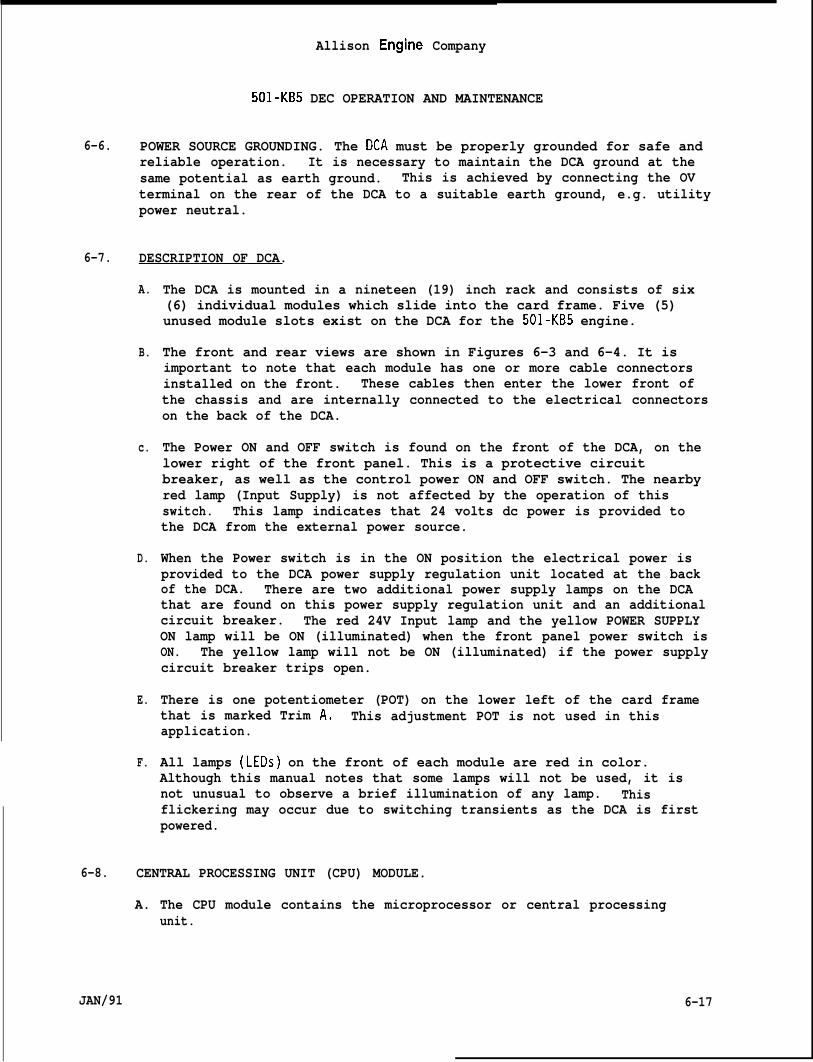
Allison Engine Company
501-KB5 DEC OPERATION AND MAINTENANCE
6-6. POWER SOURCE GROUNDING. The DCA must be properly grounded for safe andreliable operation. It is necessary to maintain the DCA ground at thesame potential as earth ground. This is achieved by connecting the OVterminal on the rear of the DCA to a suitable earth ground, e.g. utilitypower neutral.
6-7. DESCRIPTION OF DCA.
A.
B.
c.
D.
E.
F.
The DCA is mounted in a nineteen (19) inch rack and consists of six(6) individual modules which slide into the card frame. Five (5)unused module slots exist on the DCA for the 501-KB5 engine.
The front and rear views are shown in Figures 6-3 and 6-4. It isimportant to note that each module has one or more cable connectorsinstalled on the front. These cables then enter the lower front ofthe chassis and are internally connected to the electrical connectorson the back of the DCA.
The Power ON and OFF switch is found on the front of the DCA, on thelower right of the front panel. This is a protective circuitbreaker, as well as the control power ON and OFF switch. The nearbyred lamp (Input Supply) is not affected by the operation of thisswitch. This lamp indicates that 24 volts dc power is provided tothe DCA from the external power source.
When the Power switch is in the ON position the electrical power isprovided to the DCA power supply regulation unit located at the backof the DCA. There are two additional power supply lamps on the DCAthat are found on this power supply regulation unit and an additionalcircuit breaker. The red 24V Input lamp and the yellow POWER SUPPLYON lamp will be ON (illuminated) when the front panel power switch isON. The yellow lamp will not be ON (illuminated) if the power supplycircuit breaker trips open.
There is one potentiometer (POT) on the lower left of the card framethat is marked Trim A, This adjustment POT is not used in thisapplication.
All lamps (LEDs) on the front of each module are red in color.Although this manual notes that some lamps will not be used, it isnot unusual to observe a brief illumination of any lamp. Thisflickering may occur due to switching transients as the DCA is firstpowered.
6-8. CENTRAL PROCESSING UNIT (CPU) MODULE.
A. The CPU module contains the microprocessor or central processingunit.
JAN/91 6-17
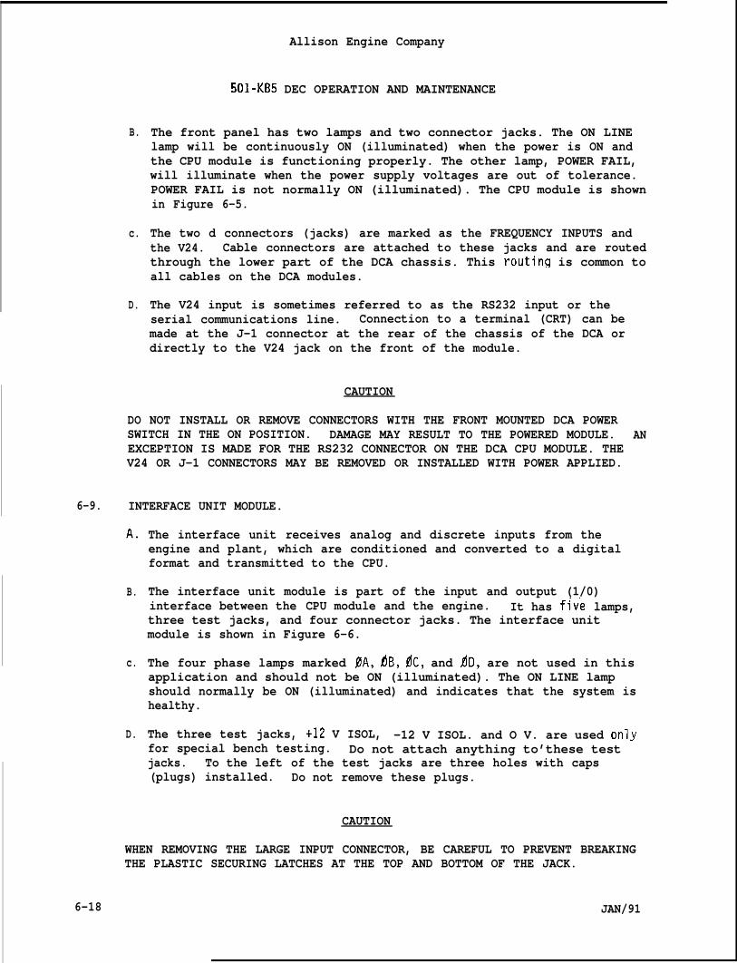
B.
c.
D.
DO
Allison Engine Company
501-KB5 DEC OPERATION AND MAINTENANCE
The front panel has two lamps and two connector jacks. The ON LINElamp will be continuously ON (illuminated) when the power is ON andthe CPU module is functioning properly. The other lamp, POWER FAIL,will illuminate when the power supply voltages are out of tolerance.POWER FAIL is not normally ON (illuminated). The CPU module is shownin Figure 6-5.
The two d connectors (jacks) are marked as the FREQUENCY INPUTS andthe V24. Cable connectors are attached to these jacks and are routedthrough the lower part of the DCA chassis. This routinq is common toall cables on the DCA modules.
The V24 input is sometimes referred to as the RS232 input or theserial communications line. Connection to a terminal (CRT) can bemade at the J-1 connector at the rear of the chassis of the DCA ordirectly to the V24 jack on the front of the module.
CAUTION
NOT INSTALL OR REMOVE CONNECTORS WITH THE FRONT MOUNTED DCA POWERSWITCH IN THE ON POSITION. DAMAGE MAY RESULT TO THE POWERED MODULE.EXCEPTION IS MADE FOR THE RS232 CONNECTOR ON THE DCA CPU MODULE. THEV24 OR J-1 CONNECTORS MAY BE REMOVED OR INSTALLED WITH POWER APPLIED.
6-9. INTERFACE UNIT MODULE.
AN
A,
B.
c.
D.
The interface unit receives analog and discrete inputs from theengine and plant, which are conditioned and converted to a digitalformat and transmitted to the CPU.
The interface unit module is part of the input and output (1/0)interface between the CPU module and the engine. It has f~v’e lamps,three test jacks, and four connector jacks. The interface unitmodule is shown in Figure 6-6.
The four phase lamps marked PA, dB, dC, and ~D, are not used in thisapplication and should not be ON (illuminated). The ON LINE lampshould normally be ON (illuminated) and indicates that the system ishealthy.
The three test jacks, +12 V ISOL, -12 V ISOL. and O V. are used onlvfor special bench testing. Do not attach anything to’these test “jacks. To the left of the test jacks are three holes with caps(plugs) installed. Do not remove these plugs.
CAUTION
WHEN REMOVING THE LARGE INPUT CONNECTOR, BE CAREFUL TO PREVENT BREAKINGTHE PLASTIC SECURING LATCHES AT THE TOP AND BOTTOM OF THE JACK.
6-18 JAN/91
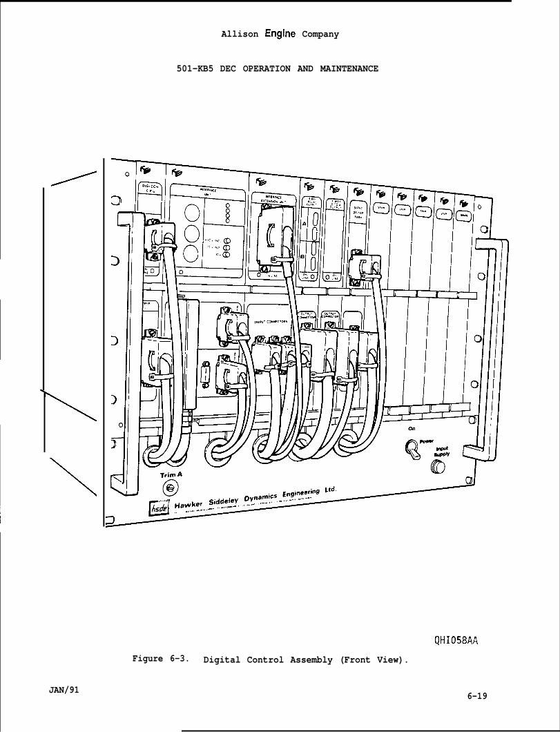
\
Allison Engine Company
501-KB5 DEC OPERATION AND MAINTENANCE
\
I
Figure 6-3. Digital Control Assembly (Front View).
JAN/91 6-19
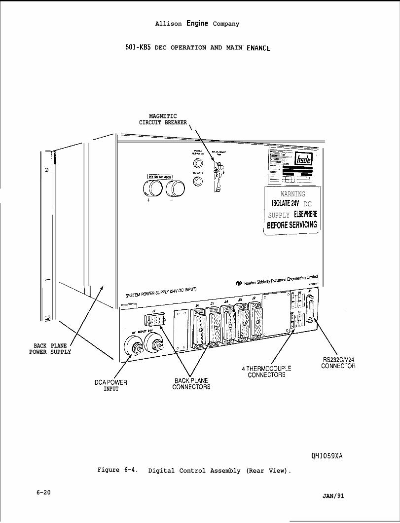
\
(\BACK PLANEPOWER SUPPLY
Allison Engine Company
501-KB5 DEC OPERATION AND MAIN-
MAGNETICCIRCUIT BREAKER
\
ENANCE
WARNINGISOLATE24V DC
I SUPPLY EMWHERE
c
DCAPOWERINPUT
Figure 6-4.
6-20
CONNECTOW
QHI059XA
Digital Control Assembly (Rear View).
JAN/91
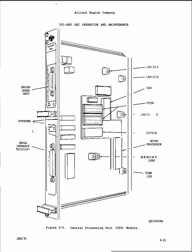
ENGINESPEEDINPUT
—
Allison Engine Company
UVPROMS -
\
SERIALINTERFACERS232C124V ~
501-KB5 DEC OPERATION AND MAINTENANCE
J I
1 I
1 I
GiD-D-01
.
,
.
/ ‘AM
— LINKCH C
— EEPROM
MICROPROCESSOR
— M E M O R YLINKS
~ TIMELINK
QHI060XA
6-21
Figure 6-5. Central Processing Unit (CPU) Module,
JAN/91
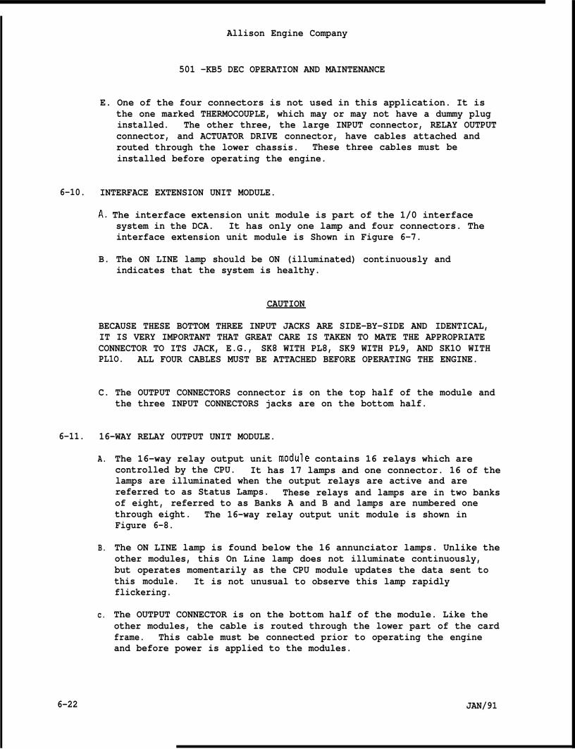
Allison Engine Company
501 -KB5 DEC OPERATION AND MAINTENANCE
E. One of the four connectors is not used in this application. It isthe one marked THERMOCOUPLE, which may or may not have a dummy pluginstalled. The other three, the large INPUT connector, RELAY OUTPUTconnector, and ACTUATOR DRIVE connector, have cables attached androuted through the lower chassis. These three cables must beinstalled before operating the engine.
6-10. INTERFACE EXTENSION UNIT MODULE.
A. The interface extension unit module is part of the 1/0 interfacesystem in the DCA. It has only one lamp and four connectors. Theinterface extension unit module is Shown in Figure 6-7.
B. The ON LINE lamp should be ON (illuminated) continuously andindicates that the system is healthy.
CAUTION
BECAUSE THESE BOTTOM THREE INPUT JACKS ARE SIDE-BY-SIDE AND IDENTICAL,IT IS VERY IMPORTANT THAT GREAT CARE IS TAKEN TO MATE THE APPROPRIATECONNECTOR TO ITS JACK, E.G., SK8 WITH PL8, SK9 WITH PL9, AND SK1O WITHPL1O. ALL FOUR CABLES MUST BE ATTACHED BEFORE OPERATING THE ENGINE.
C. The OUTPUT CONNECTORS connector is on the top half of the module andthe three INPUT CONNECTORS jacks are on the bottom half.
6-11. 16-WAY RELAY OUTPUT UNIT MODULE.
A.
B.
c.
6-22
The 16-way relay output unit module contains 16 relays which arecontrolled by the CPU. It has 17 lamps and one connector. 16 of thelamps are illuminated when the output relays are active and arereferred to as Status Lamps. These relays and lamps are in two banksof eight, referred to as Banks A and B and lamps are numbered onethrough eight. The 16-way relay output unit module is shown inFigure 6-8.
The ON LINE lamp is found below the 16 annunciator lamps. Unlike theother modules, this On Line lamp does not illuminate continuously,but operates momentarily as the CPU module updates the data sent tothis module. It is not unusual to observe this lamp rapidlyflickering.
The OUTPUT CONNECTOR is on the bottom half of the module. Like theother modules, the cable is routed through the lower part of the cardframe. This cable must be connected prior to operating the engineand before power is applied to the modules.
JAN/91
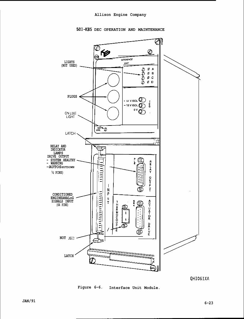
Allison Engine Company
LIGHTS(NOT USED)
PLUGS
501-KB5 DEC OPERATION AND MAINTENANCE
RELAY ANDINDICATORLAMPS
DRIVE OUTPUT- SYSTEM HEALTHY- WARNING-AUTOSHUTDOWN
{15 PINS)
CONDITIONEDENGINEANALoGSIGNALS INPUT
(64 PINS)
NOT usED
+ 12 VISOL CDT
-’2v’s”L~ E
‘“m T
12i--1=‘1-FiB1-
1-1-1-1-
,-
/ /=
[I
,-
1=
I Pm
I L~‘a
uT
/—
.
LATCH
6-23
Figure 6-6. Interface Unit Module.
JAN/91
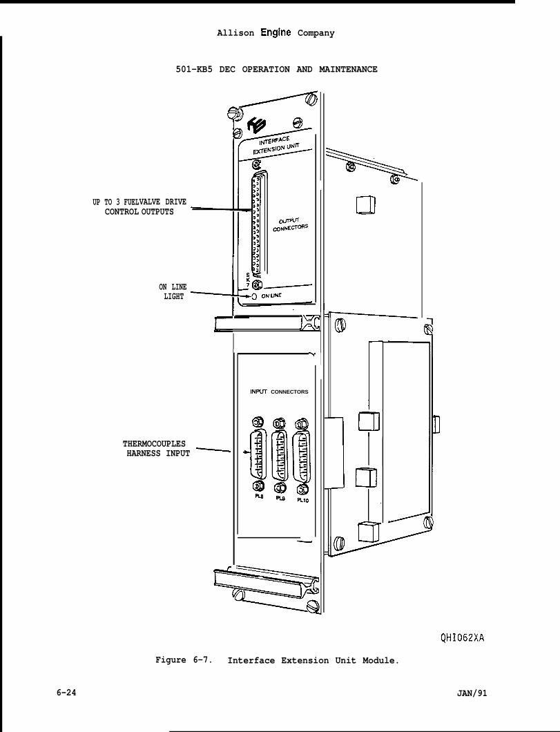
UP TO 3 FUELCONTROL
Allison Engine Company
501-KB5 DEC OPERATION AND MAINTENANCE
VALVE DRIVEOUTPUTS
ON LINELIGHT
IKc
Ih I
lNPLJl CONNECTORS
THERMOCOUPLESHARNESS INPUT ~
—
L!l
rm
QHI062XA
Figure 6-7. Interface Extension Unit Module.
6-24 JAN/91
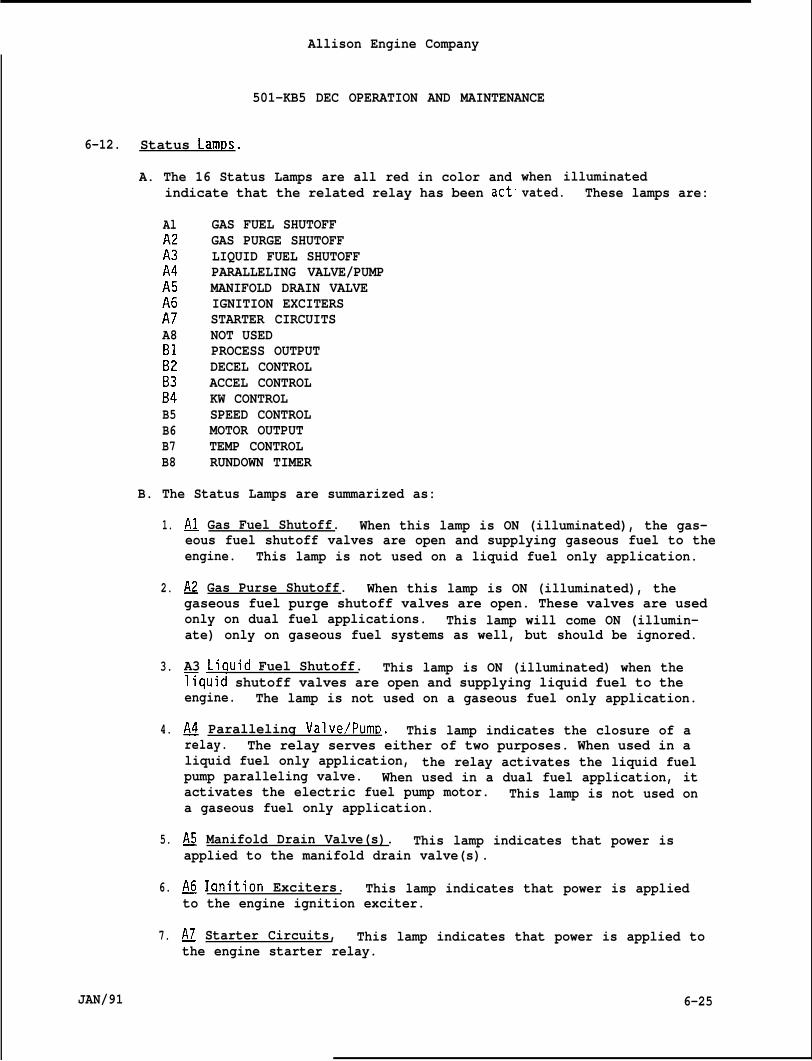
Allison Engine Company
501-KB5 DEC OPERATION AND MAINTENANCE
6-12. Status Lamps.
A. The 16 Status Lamps are all red in color andindicate that the related relay has been act”
Al GAS FUEL SHUTOFFGAS PURGE SHUTOFF
;: LIQUID FUEL SHUTOFFPARALLELING VALVE/PUMP
;: MANIFOLD DRAIN VALVEIGNITION EXCITERS
:! STARTER CIRCUITSA8 NOT USED
PROCESS OUTPUT;; DECEL CONTROL
ACCEL CONTROL:: KW CONTROLB5 SPEED CONTROLB6 MOTOR OUTPUTB7 TEMP CONTROLB8 RUNDOWN TIMER
B. The Status Lamps are summarized as:
when illuminatedvated. These lamps are:
1.
2.
3.
4.
5.
6.
7.
JAN/91
~ Gas Fuel Shutoff. When this lamp is ON (illuminated), the gas-eous fuel shutoff valves are open and supplying gaseous fuel to theengine. This lamp is not used on a liquid fuel only application.
~ Gas Purse Shutoff. When this lamp is ON (illuminated), thegaseous fuel purge shutoff valves are open. These valves are usedonly on dual fuel applications. This lamp will come ON (illumin-ate) only on gaseous fuel systems as well, but should be ignored.
A3 LiQuid Fuel Shutoff. This lamp is ON (illuminated) when thefiquid shutoff valves are open and supplying liquid fuel to theengine. The lamp is not used on a gaseous fuel only application.
~ Paralleling Valve/PumR. This lamp indicates the closure of arelay. The relay serves either of two purposes. When used in aliquid fuel only application, the relay activates the liquid fuelpump paralleling valve. When used in a dual fuel application, itactivates the electric fuel pump motor. This lamp is not used ona gaseous fuel only application.
~ Manifold Drain Valve(s). This lamp indicates that power isapplied to the manifold drain valve(s).
~ Iqnition Exciters. This lamp indicates that power is appliedto the engine ignition exciter.
~ Starter Circuits, This lamp indicates that power is applied tothe engine starter relay.
6-25
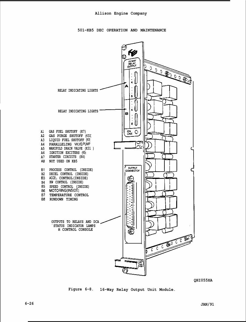
AlA2A3A4A5A6A7A6
B1B2B3B4B5B6B7B8
6-26
Allison Engine Company
501-KB5 DEC OPERATION AND MAINTENANCE
RELAY INDICATING LIGHTS
RELAY INDICATING LIGHTS
GAS FUEL SHUTOFF (K7)GAS PURGE SHUTOFF (K33)LIQUID FUEL SHUTOFF (K6)PARALLELING VALV13PUMPMANIFOLD DRAIN VALVE (K31 )IGNITION EXCITERS (K5)STARTER CIRCUITS (K4)NOT USED ON KB5
PROCESS CONTROL (INSIDE)DECEL CONTROL (INSIDE)ACCEL CONTROL(INSIDE)KW CONTROL (INSIDE)SPEED CONTROL (INSIDE)MOTORING(INSIDE)TEMPERATURE CONTROLRUNDOWN TIMING
- STATUS INDICATOR LAMPSIN CONTROL CONSOLE
Figure 6-8.
11111=J2?!?
OUTPUTS TO RELAYS AND DCA
r ouTPurCONNECTOf
PD
‘.$‘.’‘.’‘.’;>:.*,
‘>:’, ,.’,.:,
,‘ . ,‘,:>:
.’.,.>
a
\
‘mycl-!!
QHI055XA
16-Way Relay Output Unit Module.
JAN/91

Allison Engine Company
501-KB5 DEC OPERATION
8. ~. This lamp is not used.
AND MAINTENANCE
9. U Process OutDut. This lamp indicates the externaControl has control of the engine’s fuel flow.
10. ~ Decel Control. This lamp indicates that the engoperating on the decelerate fuel schedule.
1 Process
ne is
11. ~Accel Control. This lamp indicates that the engine isoperating on the accelerate fuel schedule. This lamp will beilluminated prior to starting also.
12. ~ KW Control. This lamp indicates that the engine is operatingon KW (load) governor control.
13. ~ S~eed Control. This lamp indicates that the engine isoperating on the speed governor.
Motor OutDut. This lamp is ON (illuminated) when the enginebeing MOTORED, but not started.
TemII Control. This lamp indicates that the engine is operatingthe temperature control governor.
Rundown Timer. This lamp indicates that the timer is active.engine start cannot be initiated until this lamp goes OFF.
6-13. 4-WAY D-TO-A OUTPUT UNIT MODULE.
A.
B.
c.
The 4-way D-to-A output unit module converts digital data from theCPU module into analog TOT, TIT, and engine speed output signals. Ithas one lamp and one connector. The 4-Way D-to-A output unit moduleis shown in Figure 6-9.
The ON LINE lamp is not continuously illuminated, but operatesmomentarily as the CPU module updates the data sent to the 4-wayD-to-A output unit module. It is not unusual for this lamp toflicker.
The OUTPUT CONNECTOR on the front must be connected, and is routed
stall~d before the engine is operated and powermodules.
throuqh the bottom of the chassis. The cable connector should be in-s applied to the
6-14. SERVO DRIVER PARK UNIT MODULE.
A. The servo driver park unit module has two connections to provideconnection of the two INPUT and OUTPUT electric connector.
B. The only electrical purpose is to continue the interlock chain.
JAN/91 6-27
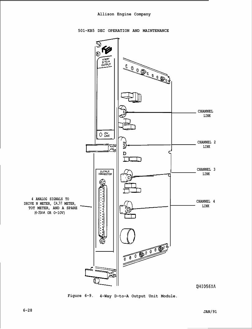
Allison Engine Company
501-KB5 DEC OPERATION AND MAINTENANCE
4 ANALOG SIGNALS TODRIVE N METER, CALTIT METER,
TOT METER, AND A SPARE ~(6-20mA OR O-1OV)
Our!=urXWNECTOR
F
DDm
CHANNELLINK
CHANNEL 2LINK
1 CHANNEL 3LINK
II.*
o000
do
I CHANNEL 4I LINK
6-28
Figure 6-9. 4-Way D-to-A Output Unit Module.
JAN/91
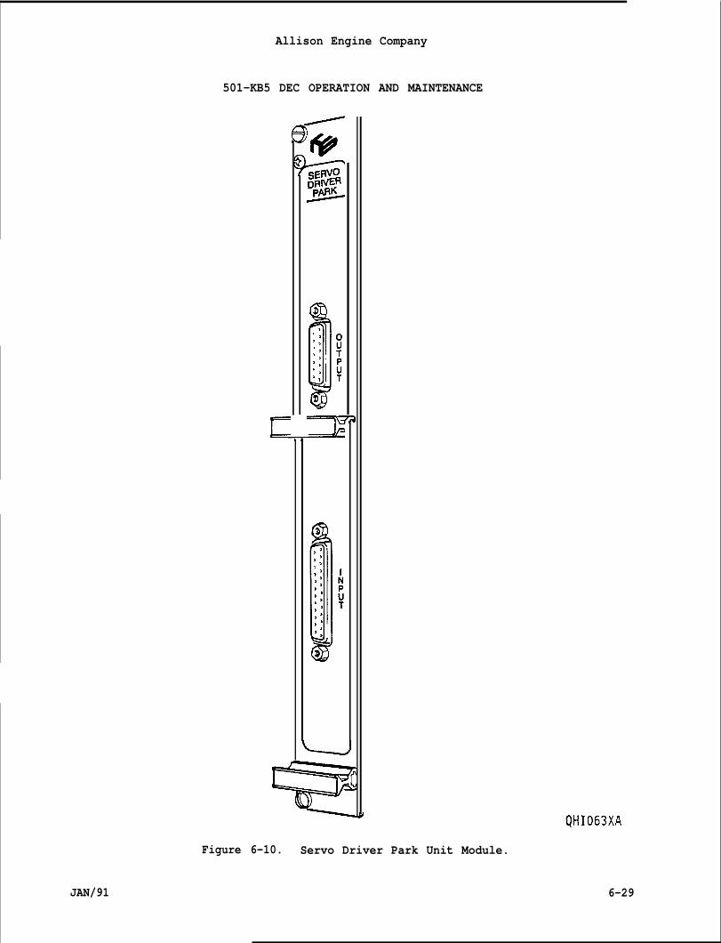
Allison Engine Company
501-KB5 DEC OPERATION AND MAINTENANCE
E
1-
Figure 6-10. Servo Driver Park Unit Module.
QHI063XA
JAN/91 6-29
Allison Engine Company
501-KB5 DEC OPERATION AND MAIN ENANCE
6-15. OPERATING THE ENGINE WITH THE DEC SYSTEM.
6-16. MOTORING.
A.
B.
c.
Motoring the engine may be desired for purging the air intake,engine,-and exhaust system of residual natural gas, for low speedmechanical tests, or for compressor cleaning. The Motoring Switchmust be held closed to facilitate motoring. When motoring, thestarter circuit is allowed to be energized, but the fuel and ignitionsystems are not energized. Motoring will continue until terminatedby the motoring timer or the Motoring Switch is released (opened).The motoring timer is adjustable. The Motoring Output status light(B6) on the 16-Way Relay Output Unit will be ON (illuminated).
The engine can be started from the Motoring mode if the engine speedis not above 2200 rpm. If above engine 2200 rpm, the start signal isignored.
Following any automatic shutoff by the motoring timer, the MotoringSwitch must be reset to OFF to permit additional motoring.
6-17. STARTING ENGINE.
A. The engine is started by momentarily closing the Start Switch. Astart is allowed if the Rundown Timer has expired, if the enginespeed is below 2200 rpm, and if no autoshutdown or malfunctionsignals are present.
B. The Reset Switch will reset any autoshutdown or malfunction signals.
6-18. STOPPING ENGINE.
A.
B.
The engine is stopped by momentarily closing the Stop Swcommand supersedes all other commands and initiates fuelThe Rundown Timer is then activated.
tch. Thisshutoff.
The, engine may also be stopped by an Autoshutdown, in which theoperator has no control. An Autoshutdown signal would be generated.Any Autoshutdown will require pressing Reset before a restart.
6-19. OPERATING MODES AND MODULATION OF ENGINE POWER. The DCA can allowengine operation in these modes: isochronous (ISOL) speed governing,droop speed governing, process control, temperature control, KW (power)control. Since each engine installation is different, not all of thesemodes will be used.
A. ISOCHRONOUS SPEED GOVERNING. Isochronous mode is used where constantspeed and variable load is encountered, as in a stand alone or standby generator set. The Governor Selection Switch must be in the
6-30 JAN/91
Allison Engine Company
501-KB5 DEC OPERATION AND MAINTENANCE
B.
c.
D.
E.
F.
Isochronous (ISOL) position (non-energized). If the generator is tonever be used in the Droop Mode, it is possible that the GovernorSelection Switch will not be installed (Refer to OEM Manual).
Droop Speed Governing. Droop mode is used when the generator setoutput is connected to an infinite (utility) bus. The GoverningSelection Switch must be in the Droop position (energized).
Process Control. Process Control mode allows the operator to controlspecial plant functions, interfacing with the engine for directcontrol of the fuel flow. The process signal may be derived from aconsole mounted potentiometer (POT) or a Process Governor. If theDCA is controlling the engine as a result of the Process Input, thenthe Process Status Lamp (Bl) on the 16-Way Relay Output will be ON(illuminated). The mode may not be used in all applications.
TEMPERATURE CONTROL.
1. This mode allows the DCA or limiting of the Calculated turbineinlet temperature (CALTIT). It may be used when operating agenerator on an infinite utility bus or simply to reduce themaximum continuous temperature limit.
2. The DCA set point is derived from a console mounted POT orequivalent. This mode may be used in all applications.
KW CONTROL. This mode allows the use of a kilowatt (KW) load sensorto limit or control the engine fuel flow. The desired load may berequested with a console mounted POT. This mode may not be used inall applications.
Dual Fuel Transfer. When a dual fuel system is used, the engine canbe started with either gaseous or liquid fuel. Transitions from onefuel source to the other is possible while the engine is running.Simply throw the fuel selector switch to the desired position (gas-eous or liquid) and the DCA will perform the transition automatically.
6-20. DCA GENERATED WARNINGS.
A. The DCA can generateexceeded or a system
warnings to indicate an operating limit is be.Droblem has occurred that warrant attention.
B.
c.
JAN/91
ng
These warnings hay be’ helpful in noting a problem which could becorrected before an autoshutdown occurs.
There is no status LED provided on the DCA that indicates a Warning.
When an abnormal operation is detected by the DCA the Warning relay(in the Interface Unit) will be energized. This is provided foroperator implementation for illuminating a remote lamp or operating awarning device. The Fault Log can be interrogated for determinationof the specific fault, even after the Warning indication is ended.
6-31
Allison Engine Company
501-KB5 DEC OPERATION AND MAINTENANCE
D. The Warnings are summarized as:
1.
2.
3.
4.
5.
6.
7.
CIT Sensor Failure -- If one of the two sensors fail or if a highdifferential exists between them, a Warning is generated. Sensorfailure may be an open or a short.
S~eed Sensor Failure -- If one of the two speed sensors is faileda Warning is generated. Sensor failure may be an open or a short.
TOT Thermocouples (T/C) Sensor Failure -- If one of the two T/Csensors is failed, a Warning is generated. Sensor fail may be anopen or a short.
Run Overtemperature -- If the CALTIT exceeds the Warning limit,but not the Autoshutdown limit during engine running.
Start Overtem~erature -- If the CALTIT exceeds the Warning limit,but not the Autoshutdown limit during engine running. Start andRun Overtemperature is recorded separately.
Overspeed -- If the engine speed exceeds the Warning limit, butnot the Autoshutdown limit.
EEPROM Write Fail -- An unsuccessful attempt at writing to theelectrically erasable programmable read only memory (EEPROM).
6-21. DCA GENERATED AUTOSHUTDOWNS.
A. The DCA can generate Autoshutdown to protect the engine from damagedue to system malfunction. In this event the fuel flow will beshutoff automatically and restart will not be possible until theexternal Reset Switch is actuated.
CAUTION
BEFORE THE ENGINE IS RESTARTED, FOLLOWING AN AUTOSHUTDOWN, THE ENGINEREMEDIED. OTHERWISESYSTEM PROBLEM (MALFUNCTION) MUST BE DETERMINED AND
FURTHER DAMAGE MAY BE DONE TO THE ENGINE.
B.
c,
There is no status LED provided on the DCA thatAutoshutdown.
ndicates an
When an abnormal operation (fault) is detected by the DCA theAutoshutdown relay (in the Interface Unit) will be ener~ized at thesame time as the fuel shutoff occurs. Th{s is provided-for operatorimplementation for illuminating a remote lamp, operating a warningdevice, or other related system functions. The Fault Log can beinterrogated for determination of the specific fault after after theAutoshutdown has occurred.
6-32 JAN/91
Allison Engine Company
501-KB5 DEC OPERATION AND MAINTENANCE
D. The autoshutdowns are summarized as:
1.
2,
3.
4.
5.
6.
7.
8.
9.
10.
11.
12.
JAN/91
CIT Sensors Failed -- When both sensors are failed. Modes offailure may be an open or a short.
S~eed Sensors Failed -- When both speed sensors are failed whileengine running an autoshutdown will be initiated as an UnderspeedShutdown. A start will be prevented by failure to detect the fuelon and ignition speed.
TOT Thermocou~le (T/C) Sensors Failed -- When both T/C sensors arefailed. Modes of failure may be an open or a short.
CJC Compensation Failed -- When the cold junction compensation(CJC) circuit for the TOT thermocouples has failed.
Start OvertemDerature -- When the CALTIT exceeds the StartAutoshutdown limit during engine starting.
Run Overtemr)erature -- When the CALTIT exceeds the RunAutoshutdown limit after engine starting.
oversDeed -- When the engine speed exceeds the Autoshutdown limit.
UndersDeed -- When the engine speed drops below the Autoshutdownlimit after completion of a start.
A/D Conversion and/or Communications Failure.
a. Fuel Meterinq Valve Malfunction -- When the gaseous and/orliquid fuel metering valve does not track the valve demand.
Normal StoD.
a. Hiqh Start Gas Pressure -- When the gaseous fuel pressure atfuel metering valve inlet exceeds the Autoshutdown limit atstart, before fuel on.
Ultra Violet Erasable Programmable Read Only Memory (UVEPROM)Failure.
a. Stagnation -- When the engine rotor acceleration rate dropsbelow the Autoshutdown limit before the start is completed.
EEPROM Corru~ted.
a. Fail-to-crank -- When the engine speed fails to reach ignitionspeed within the Autoshutdown time limit during starting.
6-33
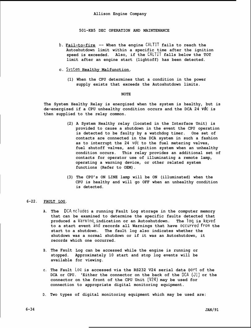
Allison Engine Company
501-KB5 DEC OPERATION AND MAINTENANCE
b. Fail-to-fire -- When the engine CALTIT fails to reach theAutoshutdown limit within a specific time after the ignitionspeed is exceeded. Also, if the CALTIT falls below the TOTlimit after an engine start (lightoff) has been detected.
c. Svstem Healthy Malfunction.
(1) When the CPU determines that a condition in the powersupply exists that exceeds the Autoshutdown limits.
NOTE
The System Healthy Relay is energized when the system is healthy, but isde-energized if a CPU unhealthy condition occurs and the DCA 24 vdc isthen supplied to the relay common.
(2) A System Healthy relay (located in the Interface Unit) isprovided to cause a shutdown in the event the CPU operationis detected to be faulty by a watchdog timer. One set ofcontacts are connected in the DCA system in such a fashionas to interrupt the 24 vdc to the fuel metering valves,fuel shutoff valves, and ignition system when an unhealthycondition occurs. This relay provides an additional set ofcontacts for operator use of illuminating a remote lamp,operating a warning device, or other related systemfunctions (Refer to OEM).
(3) The CPU’s ON LINE lamp will be ON (illuminated) when theCPU is healthy and will go OFF when an unhealthy conditionis detected.
6-22. FAULT LOG.
A.
B.
c.
D.
6-34
The DCAthat canproduced
ncludes a running Fault Log storage in the computer memorybe examined to determine the specific faults detected thata Warninq indication or an Autoshutdown. The loq is keyed
to a start event ~nd records all Warnings that have occur~ed fro~ thestart to a shutdown. The fault log also indicates whether theshutdown was a normal shutdown or if it was an Autoshutdown, itrecords which one occurred.
The Faultstopped.available
The Fault
Log can be accessed while the engine is running orApproximately 10 start and stop log events will befor viewing.
Loq is accessed via the RS232 V24 serial data Dort of theDCA or CPU. ‘Either the connector on the back of the DCA’(J1) or theconnector on the front of the CPU Unit (V24) may be used forconnection to appropriate digital monitoring equipment.
Two types of digital monitoring equipment which may be used are:
JAN/91
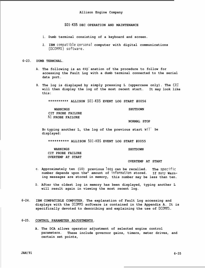
Allison Engine Company
501-KB5 DEC OPERATION AND MAINTENANCE
1.
2.
Dumb terminal consisting of a keyboard and screen.
IBM comt)atible Dersonal computer with digital communications(DCOMMS) softwa~e.
6-23. DUMB TERMINAL.
A.
B.
c.
D.
The following is an exp-accessing the Fault Logdata port.
The log is displayed by
anation of the procedure to follow forwith a dumb terminal connected to the serial
simply pressing L (uppercase only). The CRTwill then display the log of the most recent start. It may look likethis:
********** ALLISON 501-KB5 EVENT LOG START #0056
WARNINGS SHUTDOWNCIT PROBE FAILUREN1 PROBE FAILURE
NORMAL STOP
BY typing another L, the log of the previous start wil- bedisplayed:
********** ALLISON
WARNINGSCIT PROBE FAILUREOVERTEMP AT START
Approximately ten (10)
501-KB5 EVENT LOG START #0055
SHUTDOWN
OVERTEMP AT START
previous loqs can be recalled. The sDecificnumber depends upon the” amount of ~nformation stored. If ma;y Warn-ing messages are stored in memory, this number may be less than ten.
After the oldest log in memory has been displayed, typing another Lwill result again in viewing the most recent log.
6-24. IBM COMPATIBLE COMPUTER. The explanation of Fault Log accessing anddisplays with the DCOMMS software is contained in the Appendix A. It isspecifically devoted to describing and explaining the use of DCOMMS.
6-25. CONTROL PARAMETER ADJUSTMENTS.
A. The DCA allows operator adjustment of selected engine controlparameters. These include governor gains, timers, meter drives, andcertain set points,
JAN/91 6-35
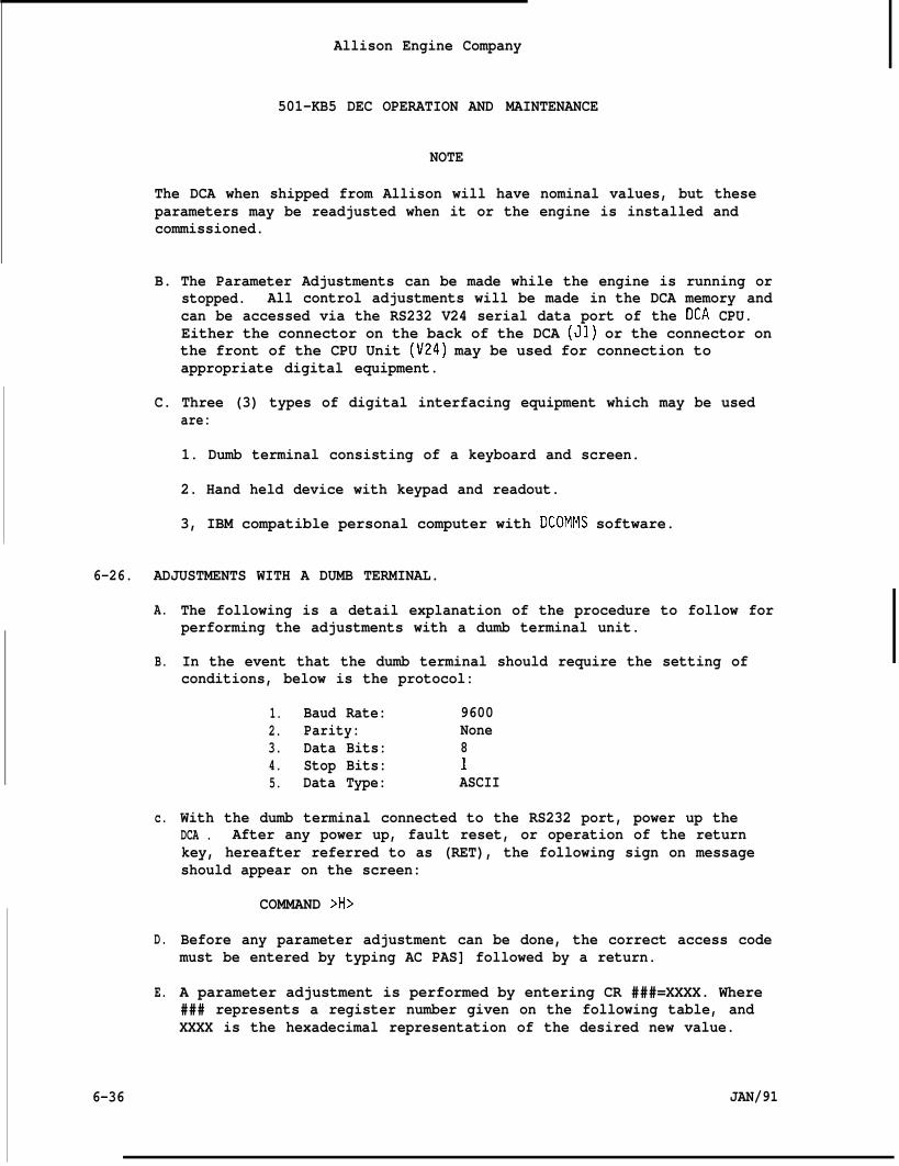
Allison Engine Company
501-KB5 DEC OPERATION AND MAINTENANCE
NOTE
The DCA when shipped from Allison will have nominal values, but theseparameters may be readjusted when it or the engine is installed andcommissioned.
B. The Parameter Adjustments can be made while the engine is running orstopped. All control adjustments will be made in the DCA memory andcan be accessed via the RS232 V24 serial data port of the DCA CPU.Either the connector on the back of the DCA (Jl) or the connector onthe front of the CPU Unit (V24) may be used for connection toappropriate digital equipment.
C. Three (3) types of digital interfacing equipment which may be usedare:
1. Dumb terminal consisting of a keyboard and screen.
2. Hand held device with keypad and readout.
3, IBM compatible personal computer with DCOMMS software.
6-26. ADJUSTMENTS WITH A DUMB TERMINAL.
A.
B.
c.
D.
E.
6-36
The following is a detail explanation of the procedure to follow forperforming the adjustments with a dumb terminal unit.
In the event that the dumb terminal should require the setting ofconditions, below is the protocol:
1. Baud Rate: 96002. Parity: None3. Data Bits: 84. Stop Bits: 15. Data Type: ASCII
With the dumb terminal connected to the RS232 port, power up theDCA . After any power up, fault reset, or operation of the returnkey, hereafter referred to as (RET), the following sign on messageshould appear on the screen:
COMMAND >H>
Before any parameter adjustment can be done, the correct access codemust be entered by typing AC PAS] followed by a return.
A parameter adjustment is performed by entering CR ###=XXXX. Where### represents a register number given on the following table, andXXXX is the hexadecimal representation of the desired new value.
JAN/91
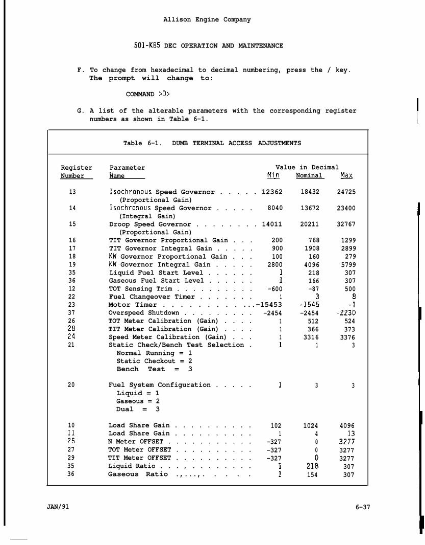
Allison Engine Company
501-KB5 DEC OPERATION AND MAINTENANCE
F. To change from hexadecimal to decimal numbering, press the / key.The prompt will change to:
COMMAND >D>
G. A list of the alterable parameters with the corresponding registernumbers as shown in Table 6-1.
Table 6-1. DUMB TERMINAL ACCESS ADJUSTMENTS
Overspeed Shutdown . . . . . . . . .TOT Meter Calibration (Gain) . . . .TIT Meter Calibration (Gain) . . . .Speed Meter Calibration (Gain) . . .Static Check/Bench Test Selection .
Normal Running = 1Static Checkout = 2Bench Test = 3
Fuel System Configuration . . . . .Liquid = 1Gaseous = 2Dual = 3
Load Share Gain . . . . . . . . . .Load Share Gain . . . . . . . . . .N Meter OFFSET . . . . . . . . . . .TOT Meter OFFSET . . . . . . . . . .TIT Meter OFFSET . . . . . . . . . .Liquid Ratio . . . , . . . . . . . .Gaseous Ratio .,...,. . . . .
-24541111
1
1021
-327-327-327
11
RegisterNumber
13
14
15
1617181935361222233726
::21
20
10
;:27293536
Parameter Value in Decimal. . . . .Name plilJ
Isochronous Speed Governor . . . . . 12362(Proportional Gain)
Isochronous Speed Governor . . . . . 8040(Integral Gain)
Droop Speed Governor . . . . . . . . 14011(Proportional Gain)
TIT Governor Proportional Gain . . . 200TIT Governor Integral Gain . . . . . 900KW Governor Proportional Gain . . . 100KW Governor Integral Gain . . . . . 2800Liquid Fuel Start Level . . . . . .Gaseous Fuel Start Level . . . . . . :TOT Sensing Trim . . . . . . . . . . -600Fuel Changeover Timer . . . . . . . 1Motor Timer . . . . . . . . . ...-15453
JAN/91 6-37
Nominal
18432
13672
20211
7681908160
4096218166-87
-154:-2454
512366
33161
3
1024400
21:154
~
24725
23400
32767
12992899279
5799307307500
8
-22;:524373
33763
3
4096
32i~32773277307307
6-38
Ho
I.
J.
K.
L.
M.
N.
o.
P.
Allison Engine Company
501-KB5 DEC OPERATION AND MAINTENANCE
The parameters can be changed. The list of the eligible parameterswith the corresponding register numbers as shown in Table 6-1.
NOTE
The DCA only responds to uppercase letters.
Parameter trimming is performed by entering DR ###represents a register number. You will see a cont.display of the current register value. Unlock thevalue by pressing the U key.
Where ###nuously updatingcurrent register
To change the current register value in the register, type M fordecrease or P for increase. For help in remembering this, think of Mfor minus and P for plus.
M or P will make a change each time the key is depressed. If the keyis held continuously, the current register value will ramp withtime. There are minimum and maximum values for each parameter whichcannot be exceeded.
Note that the current register values are displayed in hexadecimalnumbering system, i.e.. O-9 and A-F. If decimal numbering system isdesired, simply type / which is a backslash. Typing / again willtoggle back to hexadecimal. It is recommended that decimal numberingbe used.
When the current register value of the parameter is satisfactory, itmay be stored in permanent memory. Otherwise, the current registervalue will revert to the original current register value upon cyclingcontrol power ON/OFF or activating the fault reset.
Type S to permanently save the adjusted current register value. Typ-ing any other key will cause this current register value to be lostand the original current register value to be retained in memory.
Press enter to exit trim mode.
Here is a summary of the commands:
1.
2.
3.
4.
M= Decreases (minus) the current register value of a selectedparameter.
P Increases (plus) the current register value of a selectedpa;ameter.
s = Saves the current register value of a selected parameter.
/ = Toggles between decimal and hexadecimal numbering system.
JAN/91
6-27.
6-28.
6-29.
JAN/91
Allison Engine Company
501-KB5 DEC OPERATION AND MAINTENANCE
ADJUSTMENTS WITH A HAND HELD UNIT. A portable hand held unit can alsobe used to perform control adjustments. The procedure to be followed isidentical to that described above for a dumb terminal unit.
ADJUSTMENTS WITH A COMPUTER. Allison provides software, on a 5.25(5 1/4) inch (133.35 mm) flexible disk, that simplifies the DCA controladjustment procedure and is user friendly. This software, referred toas DCOMMS, is designed to be used in an IBM compatible personalcomputer. The explanation of the procedure to be used with the DCOMMSsoftware is contained in Appendix A specifically devoted to describingand explaining the use of DCOMMS.
MAINTENANCE OF DCA AND MODULES.
A.
B.
This manual was not intended to serve as an overhaul service manual,however some basic tips on troubleshooting are included. In general,if a module has no lamps (LEDs) which illuminate, it may indicate afailure. This is particularly true of the ON LINE lamps. The ONLINE lamps on all modules will illuminate continuously, with theexception of the blinking lamps on the 16 Way Relay Output and the4 Way D to A Output modules. The blinking ON LINE lamps may flash soquickly that they appear to flicker dimly.
If the Input Supply lamp on the front of the chassis does notilluminate, verify that 24 vdc is present on the 24 vdc Monitor jackson the rear of the card frame. If no voltage is present at thejacks, then the supply to the DCA should be checked. If voltage ispresent at the jacks, the DCA has a problem and service personnelshould be contacted.
CAUTION
WHEN REMOVING THE LARGE INPUT CONNECTOR ON THE INBE CAREFUL TO PREVENT THE BREAKING OF THE PLASTICTHE TOP AND BOITOMOF THE JACK.
c.
D.
ERFACE UNIT MODULE,SECURING LATCHES AT
If a module is suspected of failure. it mav be. replaced afterremoving power to the modules. Turn off the front power switch andthe remove the connector(s) on the front of the module. Loosen thelarger straight slot screws on the front and remove the modulecarefully. Remove the card edge shorting strips from the replacementand install the strips on the suspect module. Carefully install thereplacement module in the card frame. Place the suspect module inthe replacement’s packing, preferably an anti-static protective bag.Tighten the loosened screws, reconnect the module connector(s), andapply power to the modules.
If this does not remedy problem, it will be necessary to contactservice personnel.
6-39
Allison Engine Company
501-KB5 DEC OPERATION AND MAINTENANCE
ParaqraDh
7-1
7-2
7-3
7-4
7-5
7-6
7-7
7-8
7-9
7-1o
7-11
7-12
7-13
7-14
7-15
7-16
7-17
7-18
7-19
7-20
7-21
7-22
7-23
7-24
7-25
7-26
SECTION 7
ENGINE LUBRICATION SYSTEM
TABLE OF CONTENTS
Description
Description and Operation
Lubricating Oils
Oil Leaks and Troubleshooting
Oil System Cleaning
Servicing
Oil System Components
Main Pressure and Scavenge Oil Pump
(Main Oil Pump)
Description and Operation
Removal
Cleaning
Installation
Pressure Regulating Valve
Assembly Removal
Pressure Regulating Valve
Assembly Installation
Adjustment and Test
Magnetic Chip Detector
Description and Operation
Removal
Installation
Magnetic Drain Plug
Description and Operation
Removal
Installation
Oil Filter Assembly
Description and Operation
Removal
Oil Filter Element Replacement
Paqe No.
7-3
7-4
7-1o
7-15
7-16
7-18
7-18
7-18
7-18
7-21
7-21
7-21
7-21
7-22
7-22
7-22
7-23
7-23
7-23
7-23
7-23
7-24
7-24
7-24
7-24
7-25
JAN/91 7-1

Paraqra~h
7-27
7-28
7-29
7-30
7-31
7-32
7-33
7-34
7-35
7-36
Fiqure No.
Table No.
7-1
7-2
7-2
7-1
7-2
7-3
7-4
7-5
7-6
7-7
7-8
7-9
Allison Engine Company
501-KB5 DEC OPERATION AND MAINTENANCE
TABLE OF CONTENTS (CONT).
Description
Installation
External Scavenge O
(Scavenge Pump)
Description and
Removal
Installation
1 Pump Assembly
Operation
Turbine Rear Scavenge Oil Pump
Description and Operation
Removal
Inspection
I n s t a l l a t i o n
INDEX TO FIGURES
Engine Oil System Schematic
Engine Oil System Block Diagram
Hairlike Metal Particles
Main Oil Pump and Filter
Pressure Regulating Valve and Magnetic
Chip Detector
Oil Filter Assembly
External Scavenge Pump
Turbine Rear Scavenge Oil Pump
Inner Rear Exhaust Cone Puller, 6799754
INDEX TO TABLES
Lubrication Oils
Oil Leaks
Paqe No.
7-26
7-27
7-27
7-27
7-29
7-29
7-29
7-30
7-30
7-31
Paqe No.
7-5
7-7
7-17
7-19
7-20
7-26
7-28
7-32
7-33
Pacie No.
7-9
7-11
JAN/91
Allison Engine Company
. . . ..—501-KB5 DEC OPERATION AND
SECTION 7
ENGINE LUBRICATION
7-1. DESCRIPTION AND OPERATION.
MAINTENANCE
SYS
A. The engine incorporates a low-pressure,
EM
ndependent, dry sump oilsystem-(Ref. Figures 7-1 and 7:2) which includes:
1. Main pressure and scavenge oil pump assembly (Main Oil Pump)a pressure regulating valve.
2. An external scavenge pump.
3. An oil filter assembly with a filter bypass valve.
4. Check valve.
5. Scavenge pressure relief valve.
6. Magnetic chip detector (Indicating type).
7. Magnetic drain plug.
8. Turbine scavenge pump.
B.-The main oil pump is located on the center of the front face ofaccessory drive gearbox cover. Filtered oil is supplied to theoil pump inlet from the original equipment manufacturer (OEM) o
with
themain1
tank’ and filter equipment, ;S pumped through a metal element-type oilfilter assembly and check valve, through internal drilled and coredpassages, and external lines to those parts of the engine whichrequire lubrication. A pressure regulating valve located in the mainoil pump regulates the oil pressure to 50-60 psig (345-414 kPag). Acheck valve is provided in the system for installation when oilsupply tank is above the main oil pump, this will prevent oil fromleaking into the engine when the engine is not operating. Forinstallation, when oil supply tank is below the main oil pump,extreme care must be taken that the main oil pump does not loose it’sprime during downtime. Oil must not be supplied to the engine at apressure more than 5 psig (34.5 kPag) when the engine is notoperating. When engine is operating the engine oil pressure shouldbe 50-60 psig (345-414 kPag).
C. Scavenge oil is returned from the accessory gearbox sump to the oiltank by the main scavenge pump of the main oil pump. Scavenge oil isreturned to accessory drive gearbox sump from turbine rear sump bythe turbine scavenge pump. Scavenge oil is returned to the main sca-venge pump of the main oil pump from the compressor rear sump and theturbine front sump by the external scavenge pump. Scavenge oil iscarried by internal drilled passages and external lines to a common
JAN/91 7-3
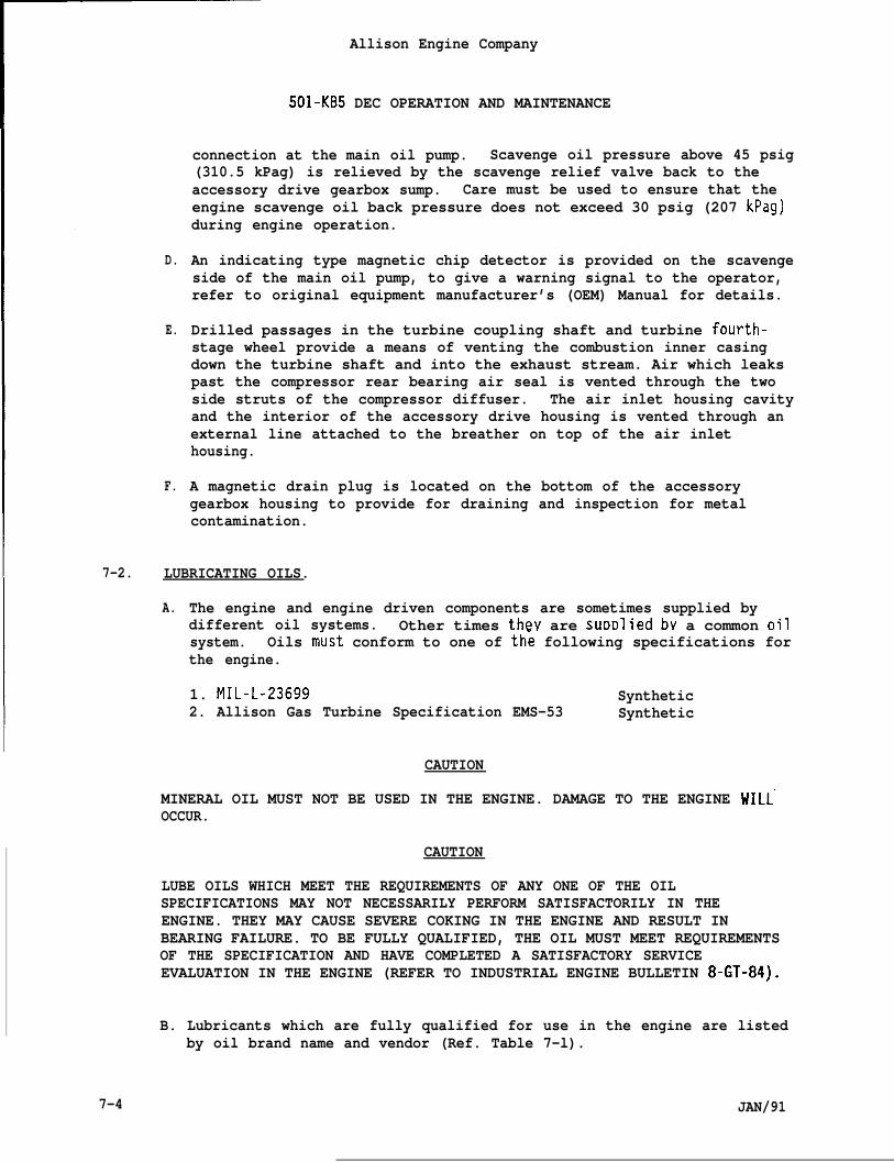
D.
E.
F.
Allison Engine Company
501-KB5 DEC OPERATION AND MAINTENANCE
connection at the main oil pump. Scavenge oil pressure above 45 psig(310.5 kPag) is relieved by the scavenge relief valve back to theaccessory drive gearbox sump. Care must be used to ensure that theengine scavenge oil back pressure does not exceed 30 psig (207 kPag)during engine operation.
An indicating type magnetic chip detector is provided on the scavengeside of the main oil pump, to give a warning signal to the operator,refer to original equipment manufacturer’s (OEM) Manual for details.
Drilled passages in the turbine coupling shaft and turbine fourth-stage wheel provide a means of venting the combustion inner casingdown the turbine shaft and into the exhaust stream. Air which leakspast the compressor rear bearing air seal is vented through the twoside struts of the compressor diffuser. The air inlet housing cavityand the interior of the accessory drive housing is vented through anexternal line attached to the breather on top of the air inlethousing.
A magnetic drain plug is located on the bottom of the accessorygearbox housing to provide for draining and inspection for metalcontamination.
7-2. LUBRICATING OILS.
A. The engine and engine driven components are sometimes supplied bydifferent oil systems. Other times they are suDDlied bv a common oilsystem. Oils m~st conform to one of th; following specifications forthe engine.
1. MIL-L-23699 Synthetic2. Allison Gas Turbine Specification EMS-53 Synthetic
CAUTION
MINERAL OIL MUST NOT BE USED IN THE ENGINE. DAMAGE TO THE ENGINE WILLOCCUR.
CAUTION
LUBE OILS WHICH MEET THE REQUIREMENTS OF ANY ONE OF THE OILSPECIFICATIONS MAY NOT NECESSARILY PERFORM SATISFACTORILY IN THEENGINE. THEY MAY CAUSE SEVERE COKING IN THE ENGINE AND RESULT INBEARING FAILURE. TO BE FULLY QUALIFIED, THE OIL MUST MEET REQUIREMENTSOF THE SPECIFICATION AND HAVE COMPLETED A SATISFACTORY SERVICEEVALUATION IN THE ENGINE (REFER TO INDUSTRIAL ENGINE BULLETIN 8-GT-84).
B. Lubricants which are fully qualified for use in the engine are listedby oil brand name and vendor (Ref. Table 7-l).
7-4 JAN/91
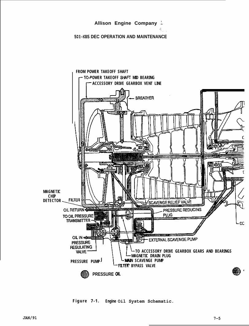
Allison Engine Company .;.!.
. .
501-KB5 DEC OPERATION AND MAINTENANCE
FROM POWER TAKEOFF SHAFTTO POWER TAKEOFF SHAH MID BEARING
k
ACCESSORY DRIVE GEARBOX VENT LINE
A
MAGNETICCHIP
DETECTOR
RE:~JING I
J ~v
L TO ACCESSORY DRIVE GEARBOX GEARS AND BEARINGSMAGNETIC DRAIN PLUG
PRESSURE PUMP MAIN SCAVENGE PUMPFILTER BYPASS VALVE
e
1PRESSURE OIL
F i g u r e 7 - 1 . Engine Oil System Schematic.
JAN/91 7-5
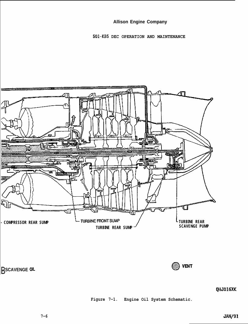
Allison Engine Company
501-KB5 DEC OPERATION AND MAINTENANCE
- COMPRESSOR REAR SUMP ~T”RBINE FRONTSIJMP1
L TURBINE REARTURBINE REAR SUMP SCAVENGE PUMP
B, SCAVENGE OIL
QHJO16XK
Figure 7-1. Engine Oil System Schematic.
JAN/917-6
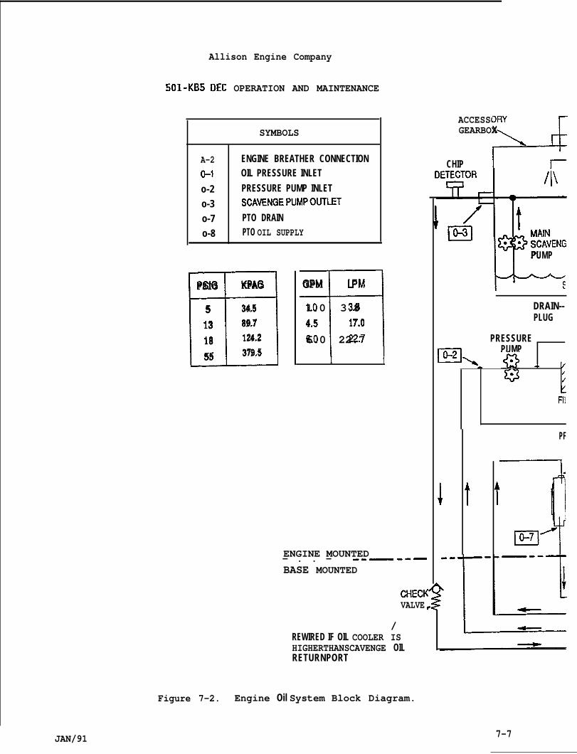
Allison Engine Company
501-KB5 DEC OPERATION AND MAINTENANCE
SYMBOLS
A-2 ENGINE BREATHER CONNECTION
0-1 OIL PRESSURE INLET
o-2 PRESSURE PUMP INLET
o-3 SCAVENGEPUMPOUTLET
o-7 PTO DRAIN
o-8 PTO OIL SUPPLY
D3PSIG KPAG
5 34.5
13 89.7
18 124.2
55 379.5 flGPM LPM
1.0 3.84.5 17.06.0 22.7
I 1
ENGINE MOUNTED— . . — --—--—BASE MOUNTED
CHECKVALVE
/REWIRED IF OIL COOLER ISHIGHERTHANSCAVENGE OILRETURNPORT
ACCESSORY
A
GEARBOX\
CHIP
L
‘1?”●
PUMP
DRAIN--PLUG
PRESSURE
3PUMP
‘>-Q A /’{/f
HI
PF
3.
PI
Figure 7-2. Engine Oil System Block Diagram.
JAN/91 7-7
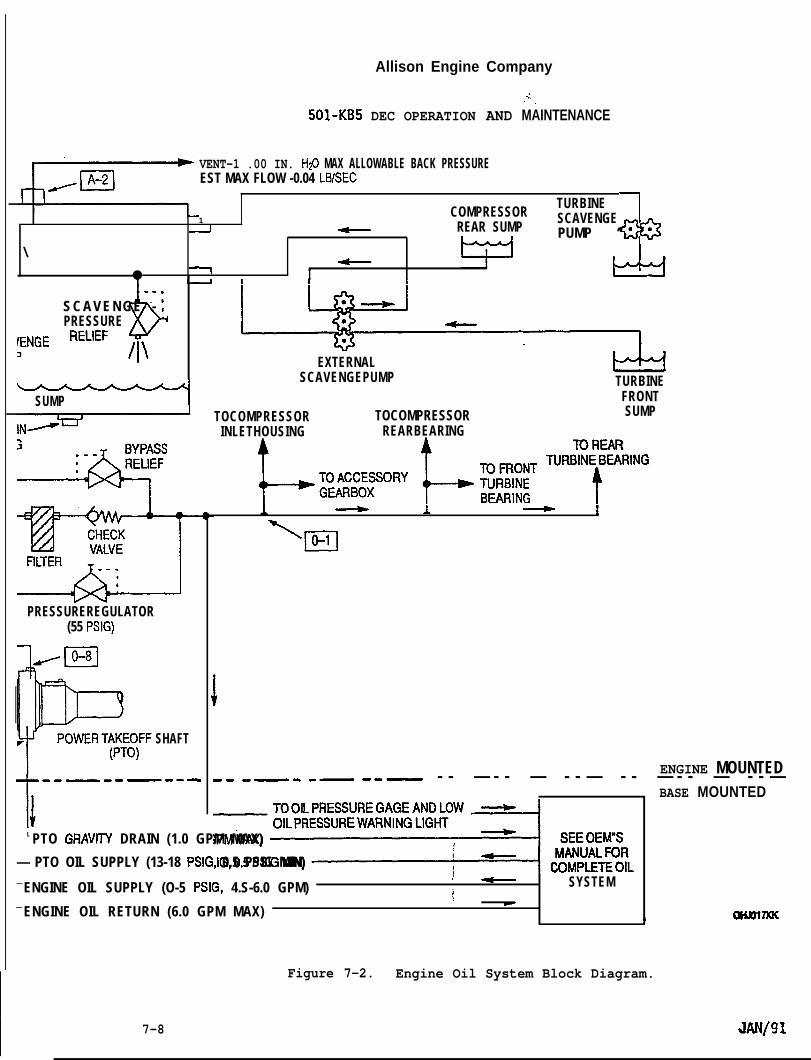
Allison Engine Company
501-KB5 DEC OPERATION AND
VENT-1 .00 IN. H@ MAX ALLOWABLE BACK PRESSUREEST MAX FLOW -0.04 LBISEC
..’.,.
MAINTENANCE
1COMPRESSOR
TURBINE
2 REAR SUMPSCAVENGE
A\
PUMP “ “
<● Y I &
bS C A V E N G E -- ;PRESSURE
:ENGE ‘EL’EF /l\
SUMP
PRESSUREREGULATOR(55 PSIG)
SHAFT
-i. .--—--- --
EXTERNALSCAVENGEPUMP TURBINE
FRONTTOCOMPRESSOR TOCOMPRESSOR SUMP
INLETHOUSING REARBEARING
L:~:::sORyL&l%rR’r’NG1 1 !
‘ o-1n
ENGINE MOUNTED.. -—- -— --— - - — - - — - - — - - — - - — - - —BASE MOUNTED
‘=&%lL
L PTO GRAVllY DRAIN (1.0 GPM MAX)
— PTO OIL SUPPLY (13-18 PSIG, 0.5 PSIG MIN)f
— ENGINE OIL SUPPLY (O-5 PSIG, 4.S-6.0 GPM) SYSTEMI
— ENGINE OIL RETURN (6.0 GPM MAX)+
.1 I
OKRnnac
Figure 7-2. Engine Oil System Block Diagram.
7-8 JAN/91

Allison Engine Company
501-KB5 DEC OPERATION AND MAINTENANCE
Table 7-1. Lubrication Oils.
Irouplumber Oil Brand Name Vendor Name
CAUTION
OILS WITH DIFFERENT GROUP NUMBERS SHOULD NOT BE MIXED. SYNTHETIC ANDMINERAL OIL SHOULD NEVER BE MIXED. DAMAGE TO THE ENGINE WILL OCCUR.
NOTE
Oils within any one group number may be mixed. Oil from different vendorswith same group numbers are rebrands of the same oil and can therefore bemixed. Oils from different group numbers should not be mixed.
9 Esso Turbo Oil 2380 Humble Oil & Refining Co.9 Exxon Turbo Oil 2380 Post Office Box 21809 Enco Turbo Oil 2380 Huston, Texas 77001
5 Mobil Jet Oil 11 Mobil Oil Corporation150 East 42nd StreetNew York, New York 10017
10 Stauffer Jet II (Castrol 205) Stauffer Chemical Company299 Park AvenueNew York, New York 10017
11 Aeroshell Turbine Oil 500 Shell International Petroleum Co50 West 50th StreetNew York, New York 10017
Castrol 5000 Burmah-Castrol Company;: Castrol 580 Castrol Research Laboratories
Whitchurch Hill, PangbourneReading, Berkshire RG8 7QR
Engl and
C. Oil samples should be taken as outlined in Section 1, Paragraph 1-30,Step C.
NOTE
Increased filtration to 100 percent of particles 1 micron or larger isrecommended as experience has shown that bearing lives are increased.
JAN/91 7-9
Allison Engine Company
501-KB5 DEC OPERATION AND MAINTENANCE
D. Oil supplied to the engine must be prefiltered through a full flowfilter capable of removing 100 percent of particles 3 micron orlarger.
E. The maximum oil temperature of inlet oil to the engine is 160°F(71”C). The minimum oil inlet temperature is -40°F (-40”C) for theengine.
F. The minimum oil supply to the engine main oil pump inlet is 4.5 gpm(17.1 Lpm) at a pressure of O-5 psig (O-34.5 kPag).
CAUTION
AIR IN THE OIL CAN RESULT IN INADEQUATE LUBRICATION AND SHORTENED ENGINELIFE DUE TO ABNORMAL BEARING WEAR.
G. Oil provided by the engine main oil pump satisfies engine bearing,gear, shaft, and other engine lubrication requirements. The lube oildelivered to the engine must be free of entrained air. Lube oillines should be bled prior to the initial engine start at the time ofinstallation.
CAUTION
PRELUBE OF THE ENGINE PRIOR TO START OR POSTLUBE AFTER COASTDOWN IS NOTREQUIRED AND MUST NOT BE ATTEMPTED. THE LUBE OIL SYSTEM IN THE ENGINEIS A DRY SUMP SYSTEM AND REQUIRES THAT THE ENGINE BE ROTATING TO PROVIDEPROPER SCAVENGING. ENGINE OIL INLET PRESSURE MUST BE LESS THAN 5 PSIG(34.5 KPAG) WHENEVER THE ENGINE IS NOT ROTATING.
7-3. OIL LEAKS AND TROUBLESHOOTING.
A.
B.
7-1o
As the engine ages, normal wear may cause the oil loss to increase;this can be corrected at overhaul. Engine oil consumption throughnormal loss, vaporizing, seeping, and expelling mostly out theexhaust can increase to 0.5 gallon (1.9 liters) per 24 hours ofoperation. The best way to measure this kind of oil loss is at theoil tank which supplies the oil system.
For leaks of the drip or seep type, some of which can exist when theengine is not operating, refer to Table 7-2, Engine Oil Leaks. Dripleaks can be measured by catching the oil in a container or bymeasuring the oil loss at the oil tank which supplies the oilsystem. To help locate oil leaks of the seeping type, the areashould be cleaned and powder (powdered Bon Ami or similar) placedaround the suspected oil leak area and the engine operated for fiveminutes. When the oil leak is found refer to Table 7-2.
JAN/91
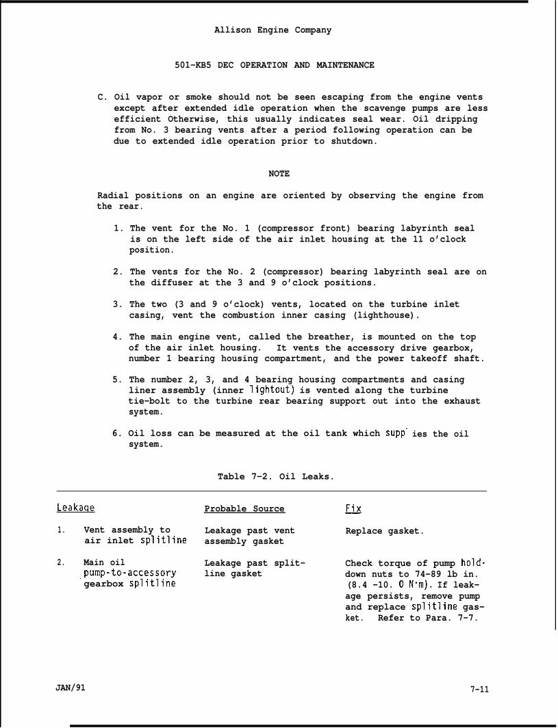
Allison Engine Company
501-KB5 DEC OPERATION AND MAINTENANCE
C. Oil vapor or smoke should not be seen escaping from the engine ventsexcept after extended idle operation when the scavenge pumps are lessefficient Otherwise, this usually indicates seal wear. Oil drippingfrom No. 3 bearing vents after a period following operation can bedue to extended idle operation prior to shutdown.
NOTE
Radial positions on an engine are oriented by observing the engine fromthe rear.
1. The vent for the No. 1 (compressor front) bearing labyrinth sealis on the left side of the air inlet housing at the 11 o’clockposition.
2. The vents for the No. 2 (compressor) bearing labyrinth seal are onthe diffuser at the 3 and 9 o’clock positions.
3. The two (3 and 9 o’clock) vents, located on the turbine inletcasing, vent the combustion inner casing (lighthouse).
4. The main engine vent, called the breather, is mounted on the topof the air inlet housing. It vents the accessory drive gearbox,number 1 bearing housing compartment, and the power takeoff shaft.
5. The number 2, 3, and 4 bearing housing compartments and casingliner assembly (inner lightout) is vented along the turbinetie-bolt to the turbine rear bearing support out into the exhaustsystem.
6. Oil loss can be measured at the oil tank which supp”system.
Table 7-2. Oil Leaks.
ies the oil
Leakaqe Probable Source ~
1. Vent assembly to Leakage past vent Replace gasket.air inlet splitline assembly gasket
2. Main oil Leakage past split- Check torque of pump hold-.pump-to-accessory line gasket down nuts to 74-89 lb in.gearbox splitline (8.4 -10. ON”m). If leak-
age persists, remove pumpand replace splitline gas-ket. Refer to Para. 7-7.
JAN/91 7-11
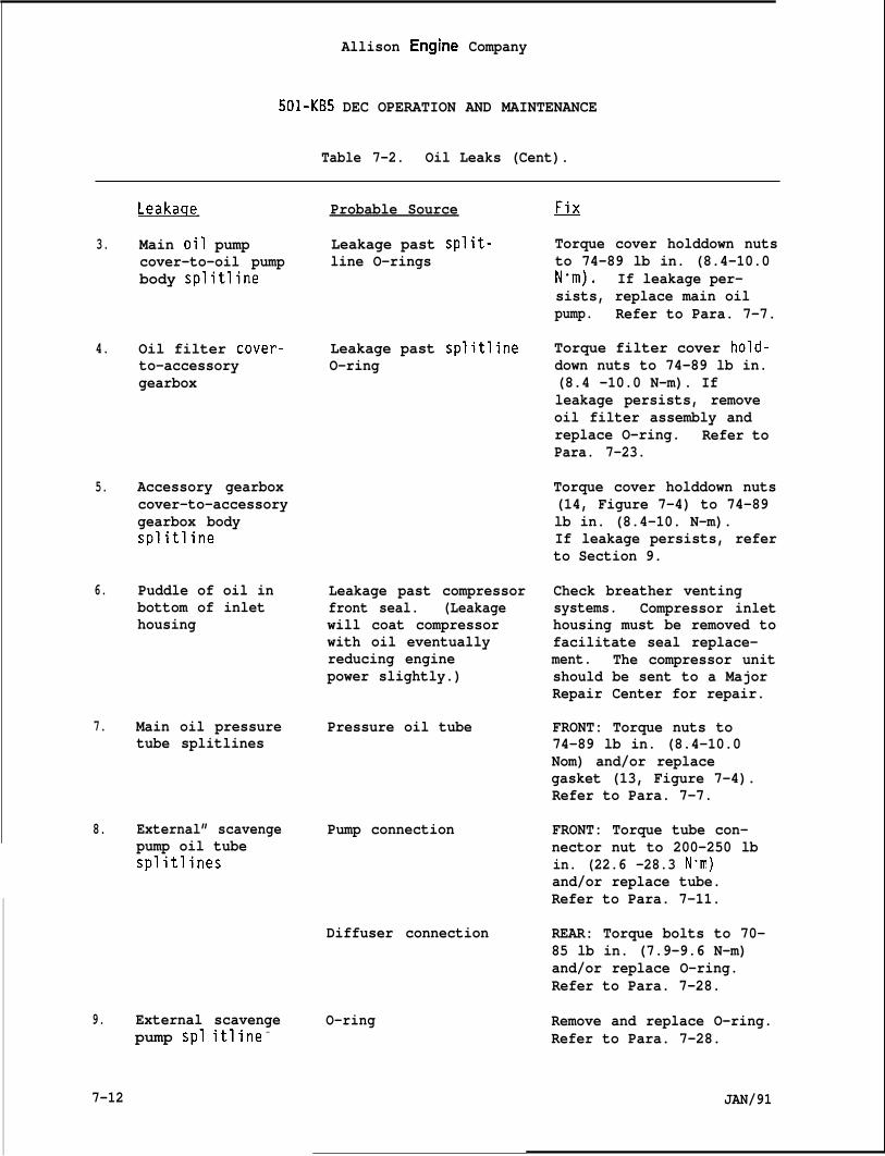
Allison Engine Company
501-KB5 DEC OPERATION AND MAINTENANCE
Table 7-2. Oil Leaks (Cent).
3.
4.
5.
6.
7.
8.
9.
Leakaqe
Main oil pumpcover-to-oil pumpbody splitline
Oil filter cover-to-accessorygearbox
Accessory gearboxcover-to-accessorygearbox bodysplitline
Puddle of oil inbottom of inlethousing
Main oil pressuretube splitlines
External” scavengepump oil tubesplitlines
External scavenge
Probable Source
Leakage past split-line O-rings
Leakage past splitlineO-ring
Leakage past compressorfront seal. (Leakagewill coat compressorwith oil eventuallyreducing enginepower slightly.)
Pressure oil tube
Pump connection
Diffuser connection
O-ringpump spl itline -
7-12
Torque cover holddown nutsto 74-89 lb in. (8.4-10.0N“m). If leakage per-sists, replace main oilpump. Refer to Para. 7-7.
Torque filter cover hold-down nuts to 74-89 lb in.(8.4 -10.0 N-m). Ifleakage persists, removeoil filter assembly andreplace O-ring. Refer toPara. 7-23.
Torque cover holddown nuts(14, Figure 7-4) to 74-89lb in. (8.4-10. N-m).If leakage persists, referto Section 9.
Check breather ventingsystems. Compressor inlethousing must be removed tofacilitate seal replace-ment. The compressor unitshould be sent to a MajorRepair Center for repair.
FRONT: Torque nuts to74-89 lb in. (8.4-10.0Nom) and/or replacegasket (13, Figure 7-4).Refer to Para. 7-7.
FRONT: Torque tube con-nector nut to 200-250 lbin. (22.6 -28.3 N“m)and/or replace tube.Refer to Para. 7-11.
REAR: Torque bolts to 70-85 lb in. (7.9-9.6 N-m)and/or replace O-ring.Refer to Para. 7-28.
Remove and replace O-ring.Refer to Para. 7-28.
JAN/91
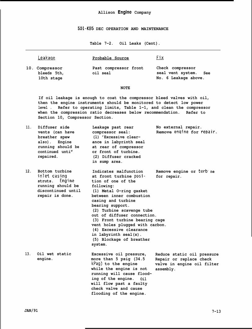
Allison Engine Company
501-KB5 DEC OPERATION AND MAINTENANCE
Table 7-2. Oil Leaks (Cent).
Leakaqe Probable Source ~
10. Compressor Past compressor front Check compressorbleeds 5th, oil seal seal vent system. See10th stage No. 6 Leakage above.
NOTE
If oil leakage is enough to coat the compressor bleed valves with oil,then the engine instruments should be monitored to detect low powerlevel . Refer to operating limits, Table 1-1, and clean the compressorwhen the compression ratio decreases below recommendation. Refer toSection 10, Compressor Section.
11. Diffuser sidevents (can havebreather spewalso). Enginerunning shouldcontinued unti”repaired.
be
12. Bottom turbineinlet casingstruts. En~inerunning should bediscontinued untilrepair is done.
13. Oil wet staticengine.
Leakage past rear No external repair.compressor seal: Remove enaine for rei)air.(l) ’Excessive clear-ance in labyrinth sealat rear of compressoror front of turbine.(2) Diffuser crackedin sump area.
Indicates malfunction Remove engine or turbat front turbine posi- for repair.tion of one of thefollowing:(1) Metal O-ring gasketbetween inner combustioncasing and turbinebearing support.(2) Turbine scavenge tubeout of diffuser connection.(3) Front turbine bearing cagevent holes plugged with carbon.(4) Excessive clearancein labyrinth seal(s).(5) Blockage of breathersystem.
ne
Excessive oil pressure, Reduce static oil pressuremore than 5 psig (34.5 Repair or replace checkkPag) to the engine valve in engine oil filterwhile the engine is not assembly.running will cause flood-ing of the engine. Oilwill flow past a faultycheck valve and causeflooding of the engine.
JAN/91 7-13
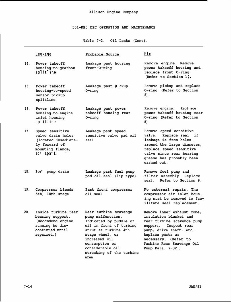
Allison Engine Company
501-KB5 DEC OPERATION AND MAINTENANCE
Table 7-2. Oil Leaks (Cent).
14.
15.
16.
17.
18.
19.
20.
Leakaqe
Power takeoffhousing-to-gearboxsplitline
Power takeoffhousing-to-speedsensor pickupsplitline
Power takeoffhousing-to-engineinlet housingsplitline
Speed sensitivevalve drain holes(located immediate-ly forward ofmounting flange,90°
Fue”
apakt. -
pump drain
Compressor bleeds5th, 10th stage
Inside turbine rearbearing support.(Recommend enginerunning be dis-continued untilrepaired.)
Probable Source
Leakage past housingfront-O-ring
Leakage past pO-ring
ckup
Leakage past powertakeoff housing rearO-ring
Leakage past speedsensitive valve pad oilseal
Leakage past fuel pumppad oil seal (lip type)
Past front compressoroil seal
Rear turbine scavengepump malfunction.Indicated by puddle ofoil in front of turbinestrut at turbine 4thstage wheel, orincreased oilconsumption orconsiderable oilstreaking of the turbinearea.
~
Remove engine. Removepower takeoff housing andreplace front O-ring(Refer
RemoveO-ring8).
Remove
to Section 8).
pickup and replace(Refer to Section
engine. Repl acepower takeoff housing rearO-ring (Refer to Section8).
Remove speed sensitivevalve. Replace seal, ifleakage is from holesaround the large diameter,replace speed sensitivevalve since rear bearinggrease has probably beenwashed out.
Remove fuel pump andfilter assembly. Replaceseal. Refer to Section 9.
No external repair. Thecompressor air inlet hous-ing must be removed to fac-ilitate seal replacement.
Remove inner exhaust cone,insulation blanket andrear turbine scavenge pumpsupport. Inspect rearpump, drive shaft, etc.Replace parts asnecessary. (Refer toTurbine Rear Scavenge OilPump Para. 7-32.)
7-14 JAN/91
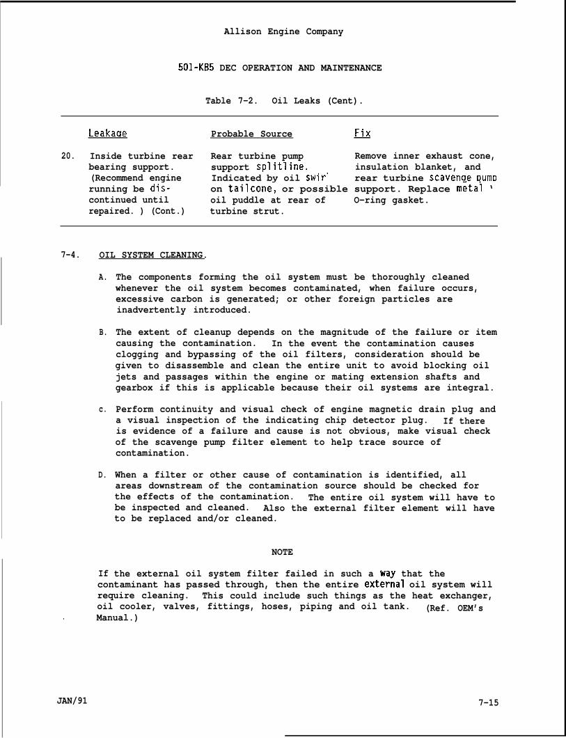
Allison Engine Company
501-KB5 DEC OPERATION AND MAINTENANCE
Table 7-2. Oil Leaks (Cent).
Leakaqe Probable Source
20. Inside turbine rear Rear turbine pumpbearing support. support splitline.(Recommend engine Indicated by oil swir”
Remove inner exhaust cone,insulation blanket, andrear turbine scavenae Dumo
running be di;- on tailcone~ or possible support. Replace m~tai ‘continued until oil puddle at rear of O-ring gasket.repaired. ) (Cont.) turbine strut.
7-4. OIL SYSTEM CLEANING.
A.
B.
c.
D.
If
The components forming the oil system must be thoroughly cleanedwhenever the oil system becomes contaminated, when failure occurs,excessive carbon is generated; or other foreign particles areinadvertently introduced.
The extent of cleanup depends on the magnitude of the failure or itemcausing the contamination. In the event the contamination causesclogging and bypassing of the oil filters, consideration should begiven to disassemble and clean the entire unit to avoid blocking oiljets and passages within the engine or mating extension shafts andgearbox if this is applicable because their oil systems are integral.
Perform continuity and visual check of engine magnetic drain plug anda visual inspection of the indicating chip detector plug. If thereis evidence of a failure and cause is not obvious, make visual checkof the scavenge pump filter element to help trace source ofcontamination.
When a filter or other cause of contamination is identified, allareas downstream of the contamination source should be checked forthe effects of the contamination. The entire oil system will have tobe inspected and cleaned. Also the external filter element will haveto be replaced and/or cleaned.
NOTE
the external oil system filter failed in such a way that thecontaminant has passed through, then the entire exter~al oil system willrequire cleaning. This could include such things as the heat exchanger,oil cooler, valves, fittings, hoses, piping and oil tank. (Ref. OEM’s
. Manual.)
JAN/91 7-15
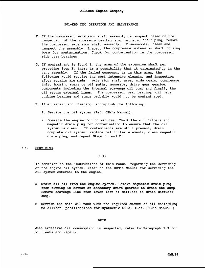
IAllison Engine Company
501-KB5 DEC OPERATION AND MAINTENANCE
F. If the compressor extension shaft assembly is suspectinspection of the accessory gearbox sump magnetic dra”the compressor extension shaftinspect the assembly. Inspectbore for contamination. Checkside gear bearings.
G. If contaminant is found in the
assembly. Disassemble,
based on then plug, removeclean and
the compressor extension shaft housingfor contamination in the compressor
area of the extension shaft perpreceding Step F, there is a possibility that it originated”up in thevent assembly. If the failed component is in this area, thefollowing would require the most intensive cleaning and inspectionafter repairs are made: extension shaft area, side gears, compressorinlet housing scavenge oil paths, accessory drive gear gearboxcomponents including the internal scavenge oil pump and finally theoil return external lines. The compressor rear bearing, oil jets,turbine bearing and sumps probably would not be contaminated.
H. After repair and cleaning, accomplish the following:
1. Service the oil system (Ref. OEM’s Manual).
2. Operate the engine for 30 minutes. Check the oil filters andmagnetic drain plug for contamination to ensure that the oilsystem is clean. If contaminants are still present, draincomplete oil system, replace oil filter elements, clean magneticdrain plug, and repeat Steps 1. and 2.
7-5. SERVICING.
NOTE
In addition to the instructions of this manual regarding the servicingof the engine oil system, refer to the OEM’s Manual for servicing theoil system external to the engine.
A. Drain all oil from the engine system. Remove magnetic drain plugfrom fitting in bottom of accessory drive gearbox to drain the sump.Remove scavenge line from lower left of diffuser to drain diffusersump.
B. Service the main oil tank with the required amount of oil conformingto Allison Specifications for Synthetic Oils. (Ref. OEM’s Manual.)
When excessive oiloil leaks and reps
NOTE
consumption is suspected, refer to Paragraph 7-3 forrs.
7-16 JAN/91
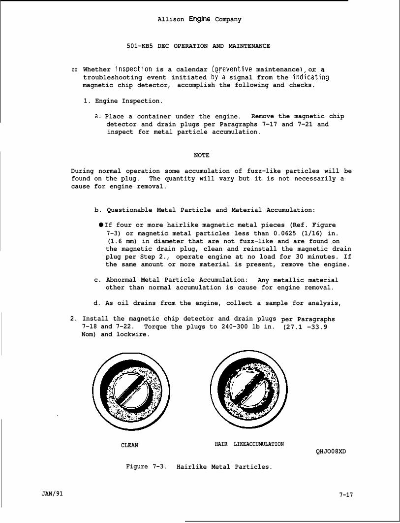
co
Allison Engine Company
501-KB5 DEC OPERATION AND MAINTENANCE
Whether insr)ection is a calendar (t)reventive maintenance) or atroubleshooting event initiated b~’a signal from the ind~catingmagnetic chip detector, accomplish the following and checks.
1. Engine Inspection.
a, Place a container under the engine. Remove the magnetic chipdetector and drain plugs per Paragraphs 7-17 and 7-21 andinspect for metal particle accumulation.
NOTE
During normal operation some accumulation of fuzz-like particles will befound on the plug. The quantity will vary but it is not necessarily acause for engine removal.
b. Questionable Metal Particle and Material Accumulation:
● If four or more hairlike magnetic metal pieces (Ref. Figure7-3) or magnetic metal particles less than 0.0625 (1/16) in.(1.6 mm) in diameter that are not fuzz-like and are found onthe magnetic drain plug, clean and reinstall the magnetic drainplug per Step 2., operate engine at no load for 30 minutes. Ifthe same amount or more material is present, remove the engine.
c. Abnormal Metal Particle Accumulation: Any metallic materialother than normal accumulation is cause for engine removal.
d. As oil drains from the engine, collect a sample for analysis,
2. Install the magnetic chip detector and drain plugs7-18 and 7-22. Torque the plugs to 240-300 lb in.Nom) and lockwire.
per Paragraphs(27.1 -33.9
CLEAN HAIR LIKEACCUMULATION
Figure 7-3. Hairlike Metal Particles.
QHJO08XD
JAN/91 7-17
7-6.
7-7.
7-8.
7-9.
7-18
Allison Engine Company
501-KB5 DEC OPERATION AND MAINTENANCE
OIL SYSTEM COMPONENTS.
NOTE
The components discussed in the following sections are the externallymounted items of the engine lube oil system.
MAIN PRESSURE AND SCAVENGE OIL PUMP (MAIN OIL PUMP).
Description and O~eration.
A. The main oil pump assembly incorporates two gear type oil pumps (apressure and a scavenge), a pressure regulating valve, and anindicating type magnetic chip detector. Oil is supplied to thepressure pump element from the OEM furnished oil supply. Scavengeoil, from the accessory drive gearbox, is returned to the oil tanktank by the scavenge pump elements of the main oil pump. Theassembly is mounted in the center of the front face of the accessorydrive gearbox.
B. The pressure regulating valve provides adjustment of engine oilpressure. It is located on the front of the main oil pump assembly.
C. The indicating-type magnetic chip detector is located in the scavengeoil outlet adapter. Ferrous metal particles present in the scavenge
- oil will adhere to the magnetic chip detector. If these metalparticles build up sufficiently to bridge the gap of the detector,the resultant circuit may be used for a warning signal or an engineshutdown (Ref. OEM’s Manual for details).
Removal.
A. Disconnect electrical connector from the magnetic chip detector.
WARN ING
TRICRESYLPHOSPHATE (TCP) AND SOME OF THE OTHER ORGANIC ADDITIVES IN THESYNTHETIC OILS ARE READILY ABSORBED BY THE SKIN AND ARE HIGHLY TOXIC.ANY PART OF THE BODY THAT COMES IN CONTACT WITH THESE OILS SHOULD BECLEANSED AS SOON AS POSSIBLE.
B. Remove the nuts (11, Figure 7-4) and washers (12) securing the oilinlet and oil lines (14 and 15) to the main oil pump (7) and removethe oil lines. Remove and discard gaskets (13). Cap all openings toprevent contamination.
JAN/91
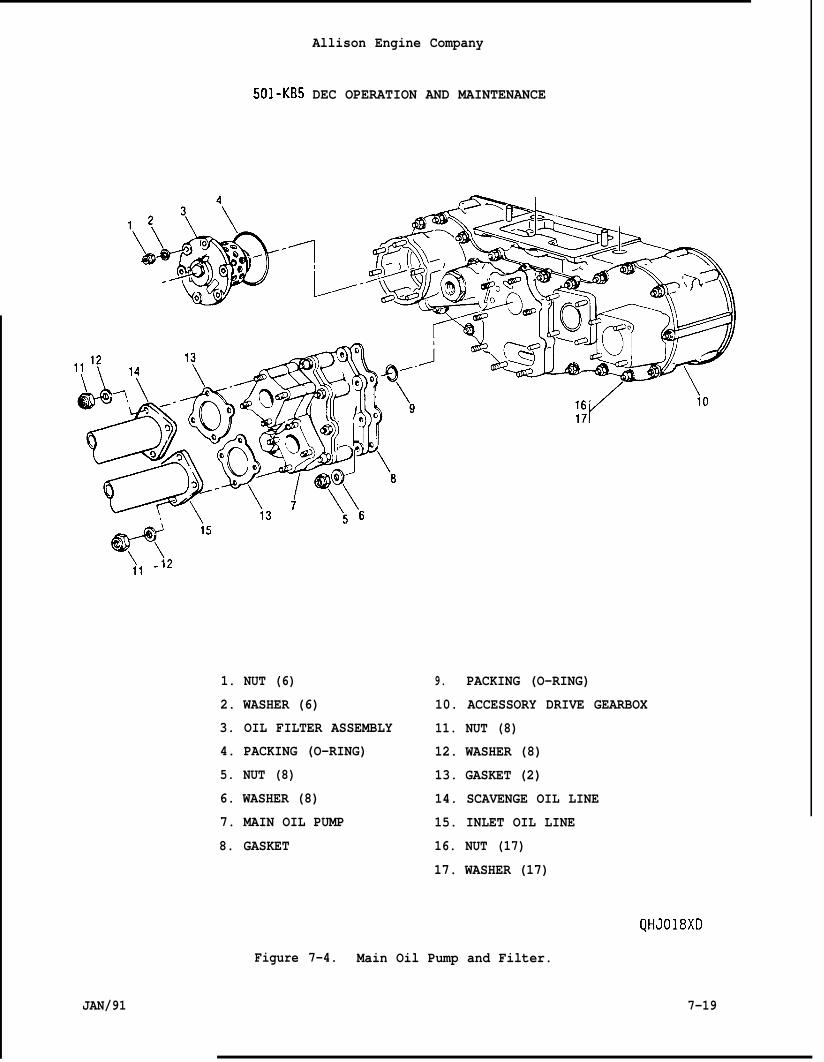
Allison Engine Company
501-KB5 DEC OPERATION AND MAINTENANCE
\11
-i2
1. NUT (6)
2. WASHER (6)
3. OIL FILTER ASSEMBLY
4. PACKING (O-RING)
5. NUT (8)
6. WASHER (8)
7. MAIN OIL PUMP
8. GASKET
9. PACKING (O-RING)
10. ACCESSORY DRIVE GEARBOX
11. NUT (8)
12. WASHER (8)
13. GASKET (2)
14. SCAVENGE OIL LINE
15. INLET OIL LINE
16. NUT (17)
17. WASHER (17)
QHJ018XD
Figure 7-4. Main Oil Pump and Filter.
JAN/91 7-19
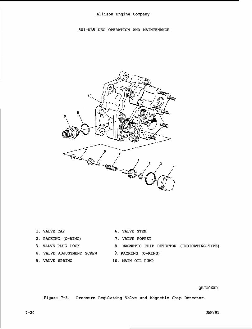
Allison Engine Company
501-KB5 DEC OPERATION AND MAINTENANCE
1. VALVE CAP 6. VALVE STEM
2. PACKING (O-RING) 7. VALVE POPPET
3. VALVE PLUG LOCK 8. MAGNETIC CHIP DETECTOR (INDICATING-TYPE)
4. VALVE ADJUSTMENT SCREW 90 PACKING (O-RING)
5. VALVE SPRING 10. MAIN OIL PUMP
QHJO06XD
Figure 7-5. Pressure Regulating Valve and Magnetic Chip Detector.
7-20 JAN/91
c.
D.
Allison Engine Company
501-KB5 DEC OPERATION AND MAINTENANCE
Remove the nuts (5), washers (6), and main oil pump (7) from theaccessory drive gearbox (10) cover.
Carefully remove the main oil pump (7), gasket (8), and O-ring (9).Discard the gasket and O-ring.” - - - ‘
-.,
7-1o. Cleaning.
A. Use mineral spirits, AMS 3160, or equivalent and allow to air dry.
B. Visually inspect for damage.
7-11. Installation.NOTE
Het O-ring and gasket with clean engine oil before installing.
A. Install O-ring (9, Figure 7-4) on the main oil pump (7) and gasket(8) on the accessory drive gearbox (10) cover mounting flange. .Then,install the main oil pump (7) and secure with nuts (5) and washers(6). Torque nuts to 74-89 lb in. (8.4 -10.0 N“m).
B. Install oil inlet and outlet gaskets (13). Install the outlet andinlet lines (14 and 15) to the main oil pump and secure with nuts(11) and washers (12). Torque nuts to 74-89 lb in. (8.4-10.0 Nom).
C. Install magnetic chip detector electrical connector and lockwire.
7-12. Pressure Requlatinq Valve Assembly Removal.
A. Remove the valve cap (1, Figure 7-5) and O-ring (2). Discard O-ring.
B. Remove the valve plug lock (3).
C. Remove valve adjustment screw (4), valve spring (5), valve stem (6),and valve poppet (7).
D. Clean and inspect pressure regulating valve assembly parts. Replacedefective parts as required.
7-13. Pressure Recmlatinq Valve Assembly Installation.
A. Lubricate all parts with clean engine lubricating oil.
B. Install valve poppet (7, Figure 7-5), valve stem (6), valve spring(5), and valve adjustment screw (4) in the main oil pump. Installthe valve screw until it is recessed approximately 0.0625 (1/16) in.(1.6 mm) within the main oil pump body (10).
JAN/91 7-21
Allison Engine Company
.— .._501-KB5 DEC OPERATION AND MAINTENANCE
C. Install valve plug lock (3). Make sure the valve plug lock engagesthe slots in both the valve adjustment screw (4) and the main oilpump body (10).
D. Install O-ring (2) and install180-220 lb in (20-25 Nom) and
7-14. Ad.iustment and Test.
valve cap (l). Torque valve cap toockwire.
A. Adjust the Pressure Regulating Valve.
1. Remove the valve cap (1, Figure 7-5) and O-ring (2). DiscardO-ring.
2. Remove the valve plug lock (3).
NOTE
One revolution of the valve adjustment screw clockwise will cause an oilpressure increase of approximately psi (21 kPa). One revolution ofthe valve adjustment screw counterclockwise will decrease the oilpressure approximately 3 psi (21 kPa).
3. Adjust the valve adjustment screw (4) as required.
4. Install valve plug lock (3), The plug lock must engage the slotsin both the valve adjustment screw and the main oil pump body.
5. Install O-ring (2) and valve cap (l). Torque valve cap to 180-220lb in. (20-25 Nom) and lockwire.
B. Test the Pressure Regulating Valve.
1.
2.
Start the engine and operate at 13,000 to 14,600 rpm.
The regulating valve should maintain 50-60 Dsi (345-414 kPa)engine-oil pr;ssure with 130-150°F (54-66eCj oil inlet ‘temperature. If it does not, shutdown engine, make an adjustmentand repeat the test.
7-15. MAGNETIC CHIP DETECTOR.
7-16. Description and ODeration.
A. The two magnets in the face of the magnetic chip detector aredesigned to attract metal particles. When the gap between the twomagnets is bridged a circuit is’ completed.
7-22 JAN/91
Allison Engine Company
501-KB5 DEC OPERATION AND MAINTENANCE
B. The magnetic chip detector includes a connector which the operatormay use for connecting an external circuit to a lamp or warningdevice to indicate when detector magnets have been bridged by debris.
7-17. Removal.
A.
B.
c.
D.
Remove electrical connector.
Remove magnetic chip detector (8, Figure 7-5) and O-ring (9) frommain oil pump (10). Discard O-ring.
Clean with a clean cloth.
Inspect (Ref. Paragraph 7-5, Step C.).
7-18. Installation.
A. Install O-ring (9, Figure 7-5) onto magnetic chip detector (8).
B. Install magnetic chip detector and O-ring into main oil pump. Torqueto 240-300 lb in. (27.1 to 33.9 N*m) and lockwire.
7-19. MAGNETIC DRAIN PLUG.
7-20. DescriI)tion and Operation.
A. The magnetic drain plug is located in the bottom of the accessorydrive gearbox housing (Ref. Section 9, Accessory Gearbox). It is inthe lowest location of the accessory drive gearbox sump.
B. The two magnets in the face of the chip detector are designed toattract metal particles. Each magnet is connected to 2 terminals onthe exterior of the magnetic drain plug. When the gap between thetwo magnets is bridged a circuit completed. An ohm meter can be usedto check if metal has bridged the gap.
7-21. Removal.
A. Remove magnetic drain plug and O-ring. Discard O-ring.
B. Clean with clean cloth.
C. Inspect (Ref. Paragraph 7-5, Step C.).
JAN/91 7-23
Allison Engine Company
501-KB5 DEC OPERATION AND MAINTENANCE
7-22. Installation.
A. Install O-ring onto magnetic drain plug.
B. Install magnetic drain plug and O-ring into accessory gearboxhousing. Torque to 240-300 lb in. (27-34 N-m) and lockwire.
7-23. OIL FILTER ASSEMBLY.
7-24. DescriL)tion and O~eration.
A. The engine oil filter assembly, located on the front face of theaccessory drive gearbox, incorporates a filter element and a checkvalve. The check valve is an elastomer seated poppet-type valve.
B. The check valve is part of the filter assembly and is removed whenthe oil filter is removed from the accessory drive gearbox.
C. Filtered oil passes through the check valve to the passages and tubeswhich distribute it to those parts of the engine which requirelubrication.
D. The check valve prevents oil from leaking into the engine when theengine is shut down,
NOTE
Access to the filter bypass valve is from the inside of the accessorydrive gearbox and is serviced at overhaul.
E. A filter bypass valve is located in the accessory drive gearbox frontcover which opens at 10 psi (69 kPa) differential pressure.
7-25. Removal.
A. Remove nuts (1, Figure 7-4) and washers (2).
NOTE
If oil filter assembly will not come out of accessoryjackscrews in the jackscrew holes (9, Figure 7-6).
B. Remove oil filter assembly (3, Figure 7-4) and O-rfront of the accessory drive housing (10).
drive gearbox, use
ng (4) from the
JAN/917-24
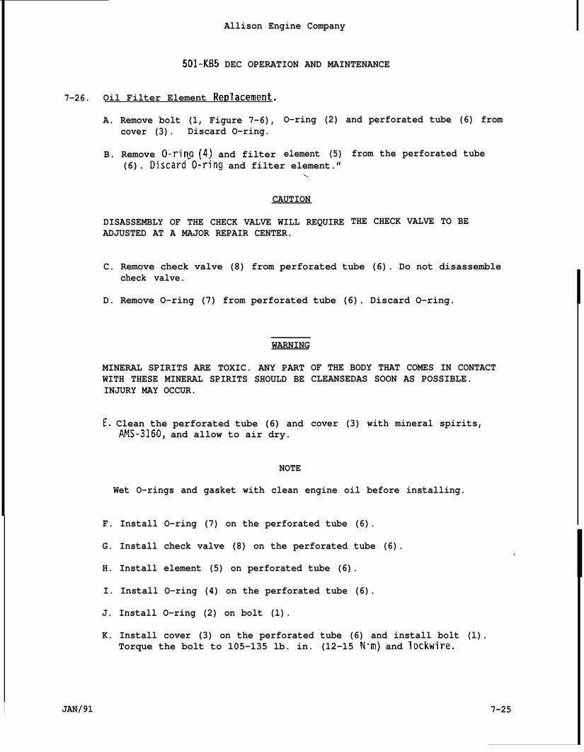
Allison Engine Company
501-KB5 DEC OPERATION AND MAINTENANCE
7-26. Oil Filter Element Rer)lacement.
A. Remove bolt (1, Figure 7-6),cover (3). Discard O-ring.
B. Remove O-rin~ (4) and filter
O-ring (2) and perforated tube (6) from
element (5)(6). Discard”O~r{ng and filter element.”
L
CAUTION
DISASSEMBLY OF THE CHECK VALVE WILL REQUIREADJUSTED AT A MAJOR REPAIR CENTER.
from the perforated tube
THE CHECK VALVE TO BE
MINERAL SPIRITS ARE TOXIC. ANY PARTWITH THESE MINERAL SPIRITS SHOULD BEINJURY MAY OCCUR.
E. Clean the perforated tube (6) andAMS-3160, and allow to air dry.
NOTE
Wet O-rings and gasket with clean engine oil before installing.
C. Remove check valve (8) from perforated tube (6). Do not disassemblecheck valve.
D. Remove O-ring (7) from perforated tube (6). Discard O-ring.
WARNING
OF THE BODY THAT COMES IN CONTACTCLEANSEDAS SOON AS POSSIBLE.
cover (3) with mineral spirits,
F. Install O-ring (7) on the perforated tube (6).
G. Install check valve (8) on the perforated tube (6).
H. Install element (5) on perforated tube (6).
I. Install O-ring (4) on the perforated tube (6).
J. Install O-ring (2) on bolt (l).
K. Install cover (3) on the perforated tube (6) and install bolt (l).Torque the bolt to 105-135 lb. in. (12-15 N“m) and lockwire.
!
7-25I JAN/91
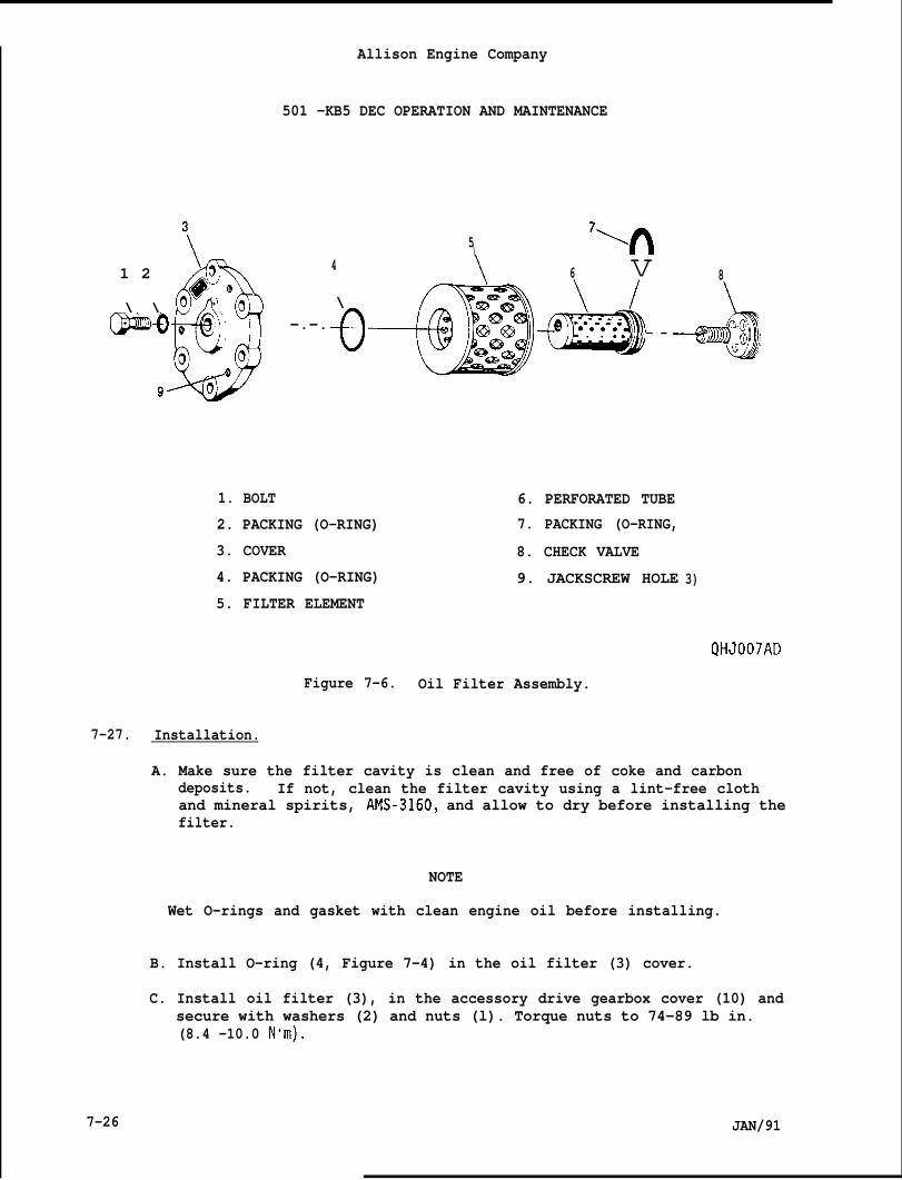
Allison Engine Company
501 -KB5 DEC OPERATION AND MAINTENANCE
5\7\n
1 2 4
\
6 v 8
\ \@ill@ –.–.
G. . ..— —
-b~;) ;’
1. BOLT 6. PERFORATED TUBE
2. PACKING (O-RING) 7. PACKING (O-RING,
3. COVER 8. CHECK VALVE
4. PACKING (O-RING) 9. JACKSCREW HOLE
5. FILTER ELEMENT3)
QHJO07AD
Figure 7-6. Oil Filter Assembly.
7-27. Installation.
A. Make sure the filter cavity is clean and free of coke and carbondeposits. If not, clean the filter cavity using a lint-free clothand mineral spirits, AMS-3160, and allow to dry before installing thefilter.
NOTE
Wet O-rings and gasket with clean engine oil before installing.
B. Install O-ring (4, Figure 7-4) in the oil filter (3) cover.
C. Install oil filter (3), in the accessory drive gearbox cover (10) andsecure with washers (2) and nuts (l). Torque nuts to 74-89 lb in.(8.4 -10.0 N“m),
7-26 JAN/91

Allison Engine Company
501-KB5 DEC OPERATION AND MAINTENANCE
7-28. EXTERNAL SCAVENGE OIL PUMP ASSEMBLY (SCAVENGE PUMP).
7-29. Description and Operation.
A.
B.
c.
D.
E.
The external scavenge oil pump (scavenge pump) is a double-elementpump incorporating three gears. It is mounted on the rear center padof the accessory drive gearbox housing.
The scavenge pump scavenges the oil from the front turbine bearingsump in the turbine inlet housing and the compressor rear bearingsump in the diffuser.
An oil line from the front turbine bearing sump extends forwardthrough the combustion inner liner casing to the diffuser and out thelower right strut.
An external line then carries the oil forward to the scavenge pump.
An oil line from the diffuser sump goes out the lower left strut andextends forward to the scavenge pump.
7-30. Removal.
WARNING
TRICRESYLPHOSPHATE (TCP) AND SOME OF THE OTHER ORGANIC ADDITIVES IN THESYNTHETIC OILS ARE READILY ABSORBED BY THE SKIN AND ARE HIGHLY TOXIC.ANY PART OF THE BODY THAT COMES IN CONTACT WITH THESE OILS SHOULD BECLEANSED AS SOON AS POSSIBLE.
A. Remove outlet tube (2, Figure 7-7).
B. Disconnect tubes (3 and 4) at the scavenge pump
C. Remove the nuts (10) securing scavenge pump (11,gearbox (1) and remove the scavenge pump.
D. Remove and discard O-rings (12 and 13).
NOTE
(11).
to accessory drive
If the scavenge pump is to be replaced, record position and remove thefollowing parts for installation on the replacement scavenge pump:
E. Remove nut (7) and elbow (6).
F. Remove unions (5 and 8).
G. Remove and discard O-rings (9).
JAN/91 7-27
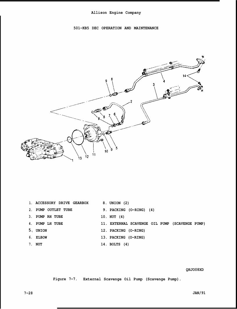
Allison Engine Company
501-KB5 DEC OPERATION AND MAINTENANCE
1.
2.
3.
4.
5,
6.
7.
7-28
ACCESSORY DRIVE GEARBOX
PUMP OUTLET TUBE
PUMP RH TUBE
PUMP LH TUBE
UNION
ELBOW
NUT
8. UNION (2)
9. PACKING (O-RING) (4)
10. NUT (4)
11. EXTERNAL SCAVENGE OIL PUMP (SCAVENGE PUMP)
12. PACKING (O-RING)
13. PACKING (O-RING)
14. BOLTS (4)
QHJO08XD
Figure 7-7. External Scavenge Oil Pump (Scavenge Pump).
JAN/91
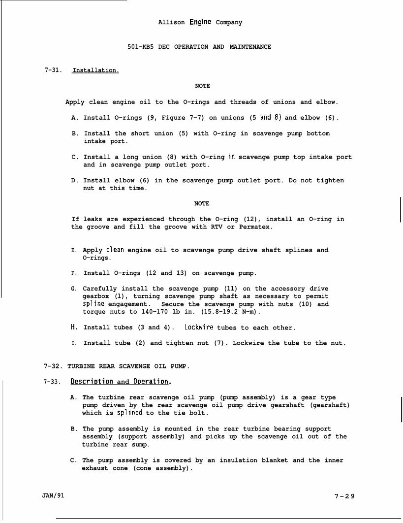
Allison Engine Company
501-KB5 DEC OPERATION AND MAINTENANCE
7-31. Installation.
NOTE
Apply clean engine oil to the O-rings and threads of unions and elbow.
A. Install O-rings (9, Figure 7-7) on unions (5 and8) and elbow (6).
B. Install the short union (5) with O-ring in scavenge pump bottomintake port.
C. Install a long union (8) with O-ring in scavenge pump top intake portand in scavenge pump outlet port.
D. Install elbow (6) in the scavenge pump outlet port. Do not tightennut at this time.
NOTE
If leaks are experienced through the O-ring (12), install an O-ring inthe groove and fill the groove with RTV or Permatex.
E.
F.
G.
H.
I.
Apply clean engine oil to scavenge pump drive shaft splines andO-rings.
Install O-rings (12 and 13) on scavenge pump.
Carefully install the scavenge pump (11) on the accessory drivegearbox (l), turning scavenge pump shaft as necessary to permitspline engagement. Secure the scavenge pump with nuts (10) andtorque nuts to 140-170 lb in. (15.8-19.2 N-m).
Install tubes (3 and 4). Lockwire tubes to each other.
Install tube (2) and tighten nut (7). Lockwire the tube to the nut.
7-32. TURBINE REAR SCAVENGE OIL PUMP.
7-33. Descri~tion and O~eration.
A. The turbine rear scavenge oil pump (pump assembly) is a gear typepump driven by the rear scavenge oil pump drive gearshaft (gearshaft)which is splined to the tie bolt.
B. The pump assembly is mounted in the rear turbine bearing supportassembly (support assembly) and picks up the scavenge oil out of theturbine rear sump.
C. The pump assembly is covered by an insulation blanket and the innerexhaust cone (cone assembly).
JAN/91 7-29
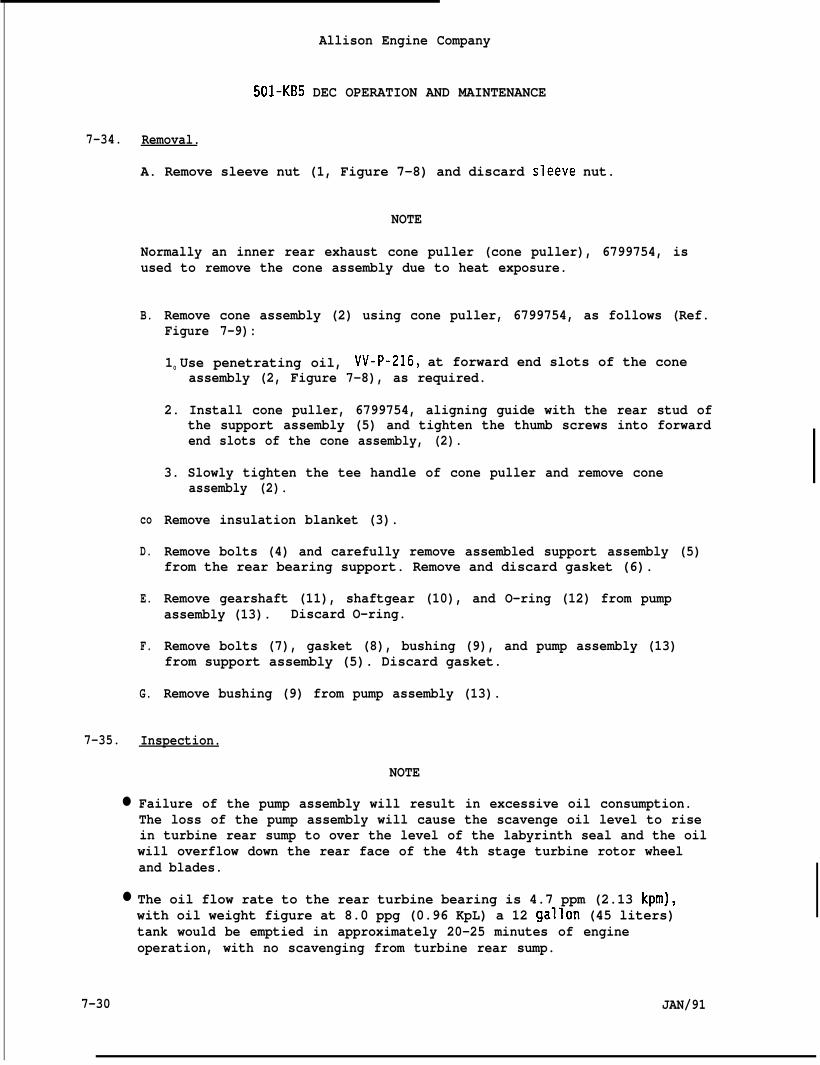
7-34.
7-35.
●
●
Allison Engine Company
501-KB5 DEC OPERATION AND MAINTENANCE
Removal.
A. Remove sleeve nut (1, Figure 7-8) and discard sleeve nut.
NOTE
Normally an inner rear exhaust cone puller (cone puller), 6799754, isused to remove the cone assembly due to heat exposure.
B.
co
D.
E.
F.
G.
Remove cone assembly (2) using cone puller, 6799754, as follows (Ref.Figure 7-9):
10 Use penetrating oil, VV-P-216, at forward end slots of the coneassembly (2, Figure 7-8), as required.
2. Install cone puller, 6799754, aligning guide with the rear stud ofthe support assembly (5) and tighten the thumb screws into forwardend slots of the cone assembly, (2).
3. Slowly tighten the tee handle of cone puller and remove coneassembly (2).
Remove insulation blanket (3).
Remove bolts (4) and carefully remove assembled support assembly (5)from the rear bearing support. Remove and discard gasket (6).
Remove gearshaft (11), shaftgear (10), and O-ring (12) from pumpassembly (13). Discard O-ring.
Remove bolts (7), gasket (8), bushing (9), and pump assembly (13)from support assembly (5). Discard gasket.
Remove bushing (9) from pump assembly (13).
Inspection.
NOTE
Failure of the pump assembly will result in excessive oil consumption.The loss of the pump assembly will cause the scavenge oil level to risein turbine rear sump to over the level of the labyrinth seal and the oilwill overflow down the rear face of the 4th stage turbine rotor wheeland blades.
The oil flow rate to the rear turbine bearing is 4.7 ppm (2.13 kpm),with oil weight figure at 8.0 ppg (0.96 KpL) a 12 gallon (45 liters)tank would be emptied in approximately 20-25 minutes of engineoperation, with no scavenging from turbine rear sump.
7-30 JAN/91
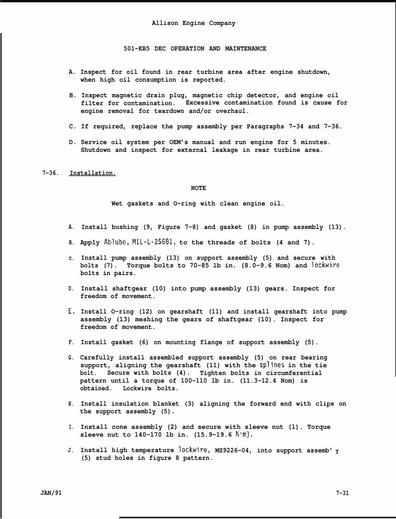
Allison Engine Company
501-KB5 DEC OPERATION AND MAINTENANCE
A. Inspect for oil found in rear turbine area after engine shutdown,when high oil consumption is reported.
B. Inspect magnetic drain plug, magnetic chip detector, and engine oilfilter for contamination. Excessive contamination found is cause forengine removal for teardown and/or overhaul.
C. If required, replace the pump assembly per Paragraphs 7-34 and 7-36.
D. Service oil system per OEM’s manual and run engine for 5 minutes.Shutdown and inspect for external leakage in rear turbine area.
7-36. Installation.
A.
B.
c.
D.
E,
F.
G.
H.
I.
J.
JAN/91
NOTE
Wet gaskets and O-ring with clean engine oil.
Install bushing (9, Figure 7-8) and gasket (8) in pump assembly (13).
Apply Ablube, MIL-L-25681, to the threads of bolts (4 and 7).
Install pump assembly (13) on support assembly (5) and secure withbolts (7). Torque bolts to 70-85 lb in. (8.0-9.6 Nom) and lockwirebolts in pairs.
Install shaftgear (10) into pump assembly (13) gears. Inspect forfreedom of movement.
Install O-ring (12) on gearshaft (11) and install gearshaft into pumpassembly (13) meshing the gears of shaftgear (10). Inspect forfreedom of movement.
Install gasket (6) on mounting flange of support assembly (5).
Carefully install assembled support assembly (5) on rear bearingsupport, aligning the gearshaft (11) with the splines in the tiebolt. Secure with bolts (4). Tighten bolts in circumferentialpattern until a torque of 100-110 lb in. (11.3-12.4 Nom) isobtained. Lockwire bolts.
Install insulation blanket (3) aligning the forward end with clips onthe support assembly (5).
Install cone assembly (2) and secure with sleeve nut (l). Torquesleeve nut to 140-170 lb in. (15.9-19.6 N-m).
Install high temperature lockwire, MS9226-04, into support assemb’(5) stud holes in figure 8 pattern.
Y
7-31
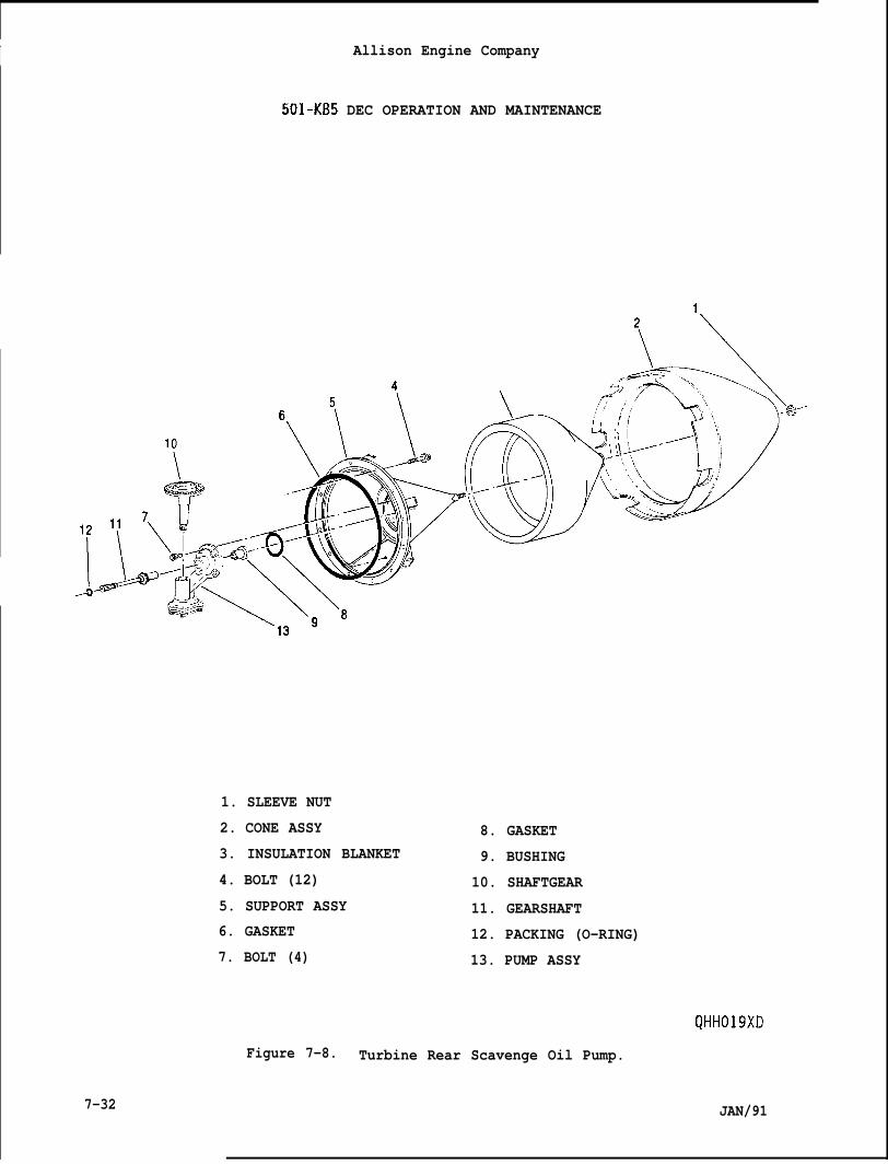
I Allison Engine Company
501-KB5 DEC OPERATION AND MAINTENANCE
1
7-32
4
1. SLEEVE NUT
2. CONE ASSY
3. INSULATION BLANKET
4. BOLT (12)
5. SUPPORT ASSY
6. GASKET
7. BOLT (4)
8. GASKET
9. BUSHING
10. SHAFTGEAR
11. GEARSHAFT
12. PACKING (O-RING)
13. PUMP ASSY
Figure 7-8. Turbine Rear Scavenge Oil Pump.
JAN/91
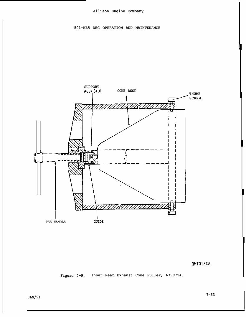
JAN/91
Allison Engine Company
501-KB5 DEC OPERATION AND MAINTENANCE
SUPPORTASSYISTUD CONE ASSY
I THUMB
I __––_J’L—– _____
SCREW
I \ laTEE HANDLE GUIDE
QHT015XA
Figure 7-9. Inner Rear Exhaust Cone Puller, 6799754.
7-33
Allison Engine Company
501-KB5 DEC OPERATION AND MAINTENANCE
paraqraph
8-1
8-2
8-3
8-4
8-5
8-6
8-7
8-8
8-9
8-10
8-11
8-12
8-13
8-14
8-15
8-16
8-17
8-18
8-19
8-20
8-21
8-22
8-23
8-24
8-25
8-26
SECTION 8
POWER TAKEOFF ASSEMBLY
TABLE OF CONTENTS
Descrir)tion
Description and Operation
Speed Sensor Pickup
Description and Operation
Removal
Inspection
Installation
Oil Nozzle
Description and Operation
Removal
Installation
Power Takeoff (PTO) Housing
Description and Operation
Removal
Installation
Power Takeoff (PTO) Shaft
Description and Operation
Removal
Installation
Adapter Housing
Description and Operation
Removal
Installation
Shaft and Tapered Couplings
Description and Operation
Removal
Installation
Paqe No,
8-3
8-3
8-3
8-5
8-6
8-6
8-9
8-9
8-9
8-9
8-10
8-10
8-10
8-13
8-16
8-16
8-17
8-17
8-17
8-17
8-19
8-19
8-19
8-19
8-20
8-22
JAN/91 8-1
Fiqure No.
8-1
8-2
8-3
8-4
8-5
8-6
8-7
8-8
8-9
8-10
8-11
8-12
8-13
8-14
Table No.
8-1
8-2
Allison Engine Company
501-KB5 DEC OPERATION AND MAINTENANCE
INDEX TO FIGURES
Title
Power Takeoff Assembly
Power Takeoff Assembly and Adapter
Coupling Details
System to Prevent Oil Mix Between
PTO and Driven Equipment
Speed Sensor Pickup
Use of Depth Gage, 6797571
PTO Housing and Adapter Housing
Midbearing Guide Tool, 6797753
Roller Retainer Tool, 6797881
Assembled PTO Shaft Assembly
Installation Measurement
Bearing Pulling Fixture, 6797754
Bearing Inner Race Pusher, 6797756
Use of Main Drive Coupling Tool, 6798754
Tapered Coupling and Input Shaft
Dimension B Measurement
INDEX TO TABLES
.$~eed Sensor pickut) Shim Requirements-,
Paqe No.
8-4
8-4
8-5
8-8
8-8
8-11
8-13
8-14
8-16
8-18
8-18
8-21
8-22
8-24
Paqe No.
8-7
JAN/91
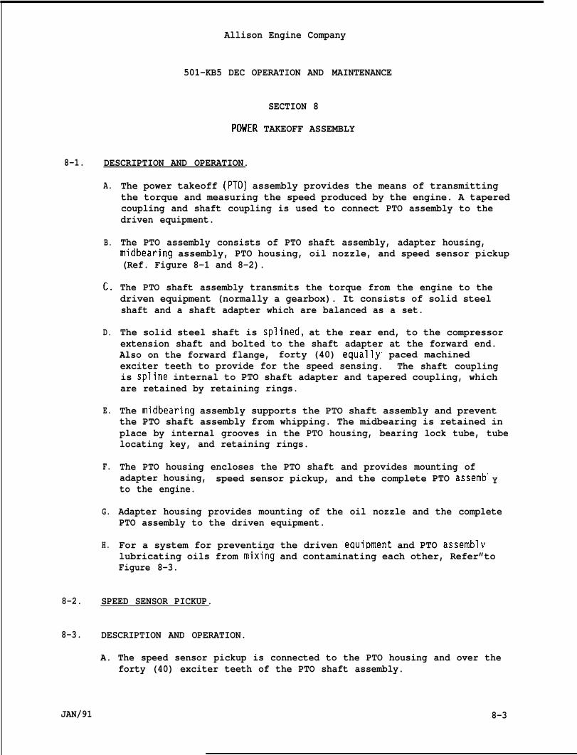
Allison Engine Company
501-KB5 DEC OPERATION AND MAINTENANCE
SECTION 8
POUER TAKEOFF ASSEMBLY
8-1. DESCRIPTION AND OPERATION.
A.
B.
c.
D.
E.
F.
G.
H.
The power takeoff (PTO) assembly provides the means of transmittingthe torque and measuring the speed produced by the engine. A taperedcoupling and shaft coupling is used to connect PTO assembly to thedriven equipment.
The PTO assembly consists of PTO shaft assembly, adapter housing,midbearing assembly, PTO housing, oil nozzle, and speed sensor pickup(Ref. Figure 8-1 and 8-2).
The PTO shaft assembly transmits the torque from the engine to thedriven equipment (normally a gearbox). It consists of solid steelshaft and a shaft adapter which are balanced as a set.
The solid steel shaft is splined, at the rear end, to the compressorextension shaft and bolted to the shaft adapter at the forward end.Also on the forward flange, forty (40) equallys paced machinedexciter teeth to provide for the speed sensing. The shaft couplingis spline internal to PTO shaft adapter and tapered coupling, whichare retained by retaining rings.
The midbearing assembly supports the PTO shaft assembly and preventthe PTO shaft assembly from whipping. The midbearing is retained inplace by internal grooves in the PTO housing, bearing lock tube, tubelocating key, and retaining rings.
The PTO housing encloses the PTO shaft and provides mounting ofadapter housing, speed sensor pickup, and the complete PTO assemb”to the engine.
Y
Adapter housing provides mounting of the oil nozzle and the completePTO assembly to the driven equipment.
For a system for preventing the driven eQuiDment and PTO assemblvlubricating oils from mixi~g and contaminating each other, Refer”toFigure 8-3.
8-2. SPEED SENSOR PICKUP.
8-3. DESCRIPTION AND OPERATION.
A. The speed sensor pickup is connected to the PTO housing and over theforty (40) exciter teeth of the PTO shaft assembly.
JAN/91 8-3
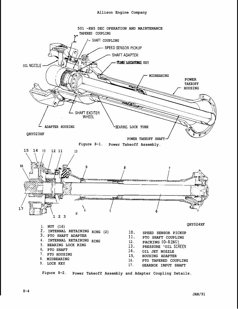
Allison Engine Company
501 -KB5 DEC OPERATION AND MAINTENANCE
r TAPERED COUPLING
/- SHAH COUPLING
%~6HnlR’p~ TUBE LOCATING KEY,OIL
MIDBEARINGPOWER
+11~ TAKEOFF
&~ HOUSING
L ADAPTER HOUSING ‘BEARING LOCK TUBE
QHY023XFPOWER TAKEOFF SHAFT1*
Figure 8-1. Power Takeoff Assembly.15 14 13 12 11 10
1
/\
. z -17 ,..w\ r
\4
1.
::4.5.6,7.8.9.
1 2 3
NUT (16)INTERNAL RETAININGPTO SHAFT ADAPTERINTERNAL RETAININGBEARING LOCK RINGPTO SHAFTPTO HOUSINGMIDBEARINGLOCK KEY
I5
QHY024XF
RING (2) SPEED SENSOR PICKUP:!: PTO SHAFT COUPLING
RING 12. PACKING (O-RING)PRESSURE ‘OIL SC~EEN
::: OIL JET NOZZLE150 HOUSING ADAPTER16. PTO TAPERED COUPLING17. GEARBOX INPUT SHAFT
8-4
Figure 8-2. Power Takeoff Assembly and Adapter Coupling Details.
JAN/91
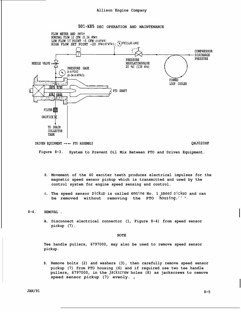
501-KB5
FLOW METER AND SWtTCH
Allison Engine Company
DEC OPERATION AND MAINTENANCE
NOMINAL FLOW 12 CFM (0.34 M3/MIN.)LOW FLOW SET POINT -5 CFM (014 M3/lWN.)HIGH FLOW SET POINT -20 CFM(057M3MIN) @pREss~REGAGE
NEEDLE VALVEPRESSURE GAGE
PTO SHAFT
1 ---t, COMPRESSOR, DISCHARGEPRESSURE PRESSUREREGULATINGVALVE20 PSIG (138 KPAG)
FINNEDLOOP COOLER
FILTER
T
ORIFICE (
TO DRAINCOLLECTORTANK
DRIVEN EQUIPMENT +- PTO ASSEMBLY QHJ020XF
Figure 8-3. System to Prevent Oil Mix Between PTO and Driven Equipment.
B.
c.
Movement of the 40 exciter teeth produces electrical impulses for themagnetic speed sensor pickup which is transmitted and used by thecontrol system for engine speed sensing and control.
The speed sensor picku~ is called enqine No. 1 sDeed DickuD and canbe removed without removing the PTO fiousing. r r ‘
8-4. REMOVAL .
A. Disconnect electrical connector (1, Figure 8-4) from speed sensorpickup (7).
NOTE
Tee handle pullers, 6797000, may also be used to remove speed sensorpickup.
B. Remove bolts (2) and washers (3), then carefully remove speed sensorpickup (7) from PTO housing (6) and if required use two tee handlepullers, 6797000, in the jackscrew holes (8) as jackscrews to removespeed sensor pickup (7) evenly. ,
JAN/91I
8-5
Allison Engine Company
501-KB5 DEC OPERATION AND MAINTENANCE
C. Remove shim(s) (4) and O-ring (5). Measure thickness of shim andrecord for installation. Discard O-ring.
D. Inspect pickup block assembly (9) for damage and stud for damage.
E. If required, remove pickup block assembly per Paragraph 8-13, Step G.
8-5. INSPECTION.
A. Clean the speed sensor pickup by wiping with a clean cloth dampenedwith mineral spirits, AMS3160, and allow to air dry”.
B. Inspect to ensure continuity between pins A and B. Noreplace speed sensor pickup.
C. Inspect for no continuity between pins and pickup houscontinuity exists, replace speed sensor pickup.
continuity,
ng. If
D. If the speed sensor has an open coil or a between winding shortsuspected, replace speed sensor pickup.
CAUTION
s
IF EXCITER TEETH TO SPEED SENSOR PICKUP RUB IS EVIDENT, THIS CONDITIONMUST BE CORRECTED BEFORE RUNNING THE ENGINE.
E. Inspect the speed sensor pickup for damage due to PTO shaft exciterteeth rub. If rub has occurred, correct the cause and replace thespeed sensor pickup.
F. Inspect the speed sensor for damage (crossed threads, loose pins,etc.). Replace speed sensor pickup if damage is found.
8-6. INSTALLATION.
A. If required, install pickup block assembly (9, Figure 8-4) perParagraph 8-14, Step D.
B. If required, clean pickup block assembly (9) and speed sensor pickup(7) mounting flanges.
NOTE
Make sure the pickup block assembly’s dowel pin is inserted into thedepth gage’s dowel pin hole or clearance measurement will be a highinaccurate reading.
8-6 JAN/91
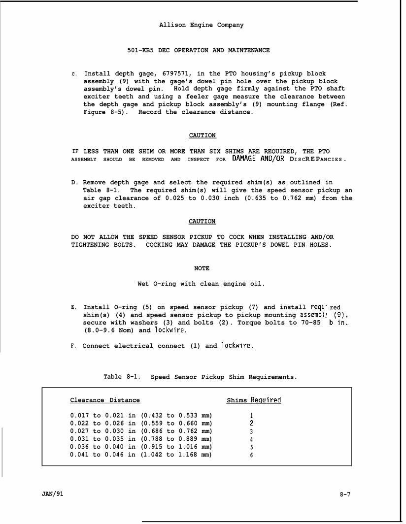
c.
IF
Allison Engine Company
501-KB5 DEC OPERATION AND MAINTENANCE
Install depth gage, 6797571, in the PTO housing’s pickup blockassembly (9) with the gage’s dowel pin hole over the pickup blockassembly’s dowel pin. Hold depth gage firmly against the PTO shaftexciter teeth and using a feeler gage measure the clearance betweenthe depth gage and pickup block assembly’s (9) mounting flange (Ref.Figure 8-5). Record the clearance distance.
CAUTION
LESS THAN ONE SHIM OR MORE THAN SIX SHIMS ARE REQUIRED, THE PTOASSEMBLY SHOULD BE REMOVED AND INSPECT FOR DAMAGE AND/OR DISCREPANCIES.
D. Remove depth gage and select the required shim(s) as outlined inTable 8-1. The required shim(s) will give the speed sensor pickup anair gap clearance of 0.025 to 0.030 inch (0.635 to 0.762 mm) from theexciter teeth.
CAUTION
DO NOT ALLOW THE SPEED SENSOR PICKUP TO COCK WHEN INSTALLING AND/ORTIGHTENING BOLTS. COCKING MAY DAMAGE THE PICKUP’S DOWEL PIN HOLES.
E.
F.
NOTE
Wet O-ring with clean engine oil.
Install O-ring (5) on speed sensor pickup (7) and install requ”shim(s) (4) and speed sensor pickup to pickup mounting assembl~secure with washers (3) and bolts (2). Torque bolts to 70-85(8.0-9.6 Nom) and Iockwire.
Connect electrical connect (1) and lockwire.
redb(;:,
.
Table 8-1. Speed Sensor Pickup Shim Requirements.
Clearance Distance Shims Reauired
0.017 to 0.021 in (0.432 to 0.533 mm)0.022 to 0.026 in (0.559 to 0.660 mm) ;0.027 to 0.030 in (0.686 to 0.762 mm) 30.031 to 0.035 in (0.788 to 0.889 mm) 40.036 to 0.040 in (0.915 to 1.016 mm) 50.041 to 0.046 in (1.042 to 1.168 mm) 6
JAN/91 8-7
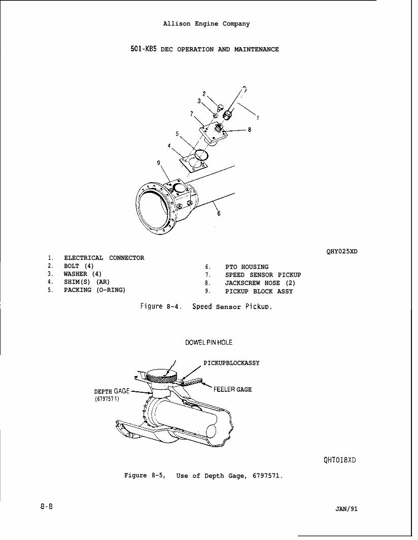
Allison Engine Company
501-KB5 DEC OPERATION AND MAINTENANCE
1. ELECTRICAL CONNECTOR2. BOLT (4) 6. PTO HOUSING3. WASHER (4) 7. SPEED SENSOR PICKUP4. SHIM(S) (AR) 8. JACKSCREW HOSE (2)5. PACKING (O-RING) 9. PICKUP BLOCK ASSY
I Figure 8-4. Speed Sensor pickuD.
QHY025XD
8-8
00WELPINHOLE
/ PICKUPBLOCKASSY
DEPTH GAGE(679757
QHT018XD
Figure 8-5, Use of Depth Gage, 6797571.
JAN/91
Allison Engine Company
501-KB5 DEC OPERATION AND MAINTENANCE
8-7. OIL NOZZLE.
8-8. DESCRIPTION AND OPERATION.
A.
B.
The oil nozzle provides lubrication for shaft adapter and tapercoupling area.
A wire mesh filter is contained in the oil nozzle for finalfiltration of the lubrication oil.
8-9. REMOVAL.
A.
B.
c.
D.
Remove pressure hose (1, Figure 8-6) from oil nozzle union (2). Ifrequired, remove union and O-ring (3). Discard O-ring.
Remove bolts (4), O-ring (5), and oil nozzle (6) from adapter housing(37). Remove and discard O-ring (5).
Remove wire mesh filter (7) from oil nozzle (6) using care not todamage wire mesh filter. Inspect for contamination.
If required, clean wire mesh filter (7) with a clean cloth damr)enedwith mineral oil, AMS3160, and allow-to dry. Inspect wire meshfilter for damage.
8-10. INSTALLATION.
NOTE
Het O-rings with clean engine oil.
A. Carefully install wire mesh filter (7, Figure 8-6) into oil nozzle(6) with taper end down.
B. Install O-ring (5) on oil nozzle (6) and install assembled oil nozzlein adapter housing (37), secure with bolts (4). Torque bolts to60-65 lb in. (6.8-7.3 Nom) and lockwire,
C. Install O-ring (3) on union (2) and install union with O-ring side inoil nozzle (6). Torque union to 55-80 lb in. (6.3-9.0 Nom).
D. Install pressure hose (1) to union (2). Retain union from turningand torque hose’s coupling nut to 80-120 lb in. (9.0-13.5 N-m).
JAN/91 8-9
Allison Engine Company
501 -KB5 DEC OPERATION AND MAINTENANCE
8-11. POWER TAKEOFF (PTO) HOUSING.
8-12. DESCRIPTION AND OPEilATION.
A.
B.
c.
The PTO housing encloses the PTO shaft with a roller type bearing(midbearing) within the PTO housing to prevent PTO shaft whip. ThePTO housing also provides mounting of the speed sensor pickup to thepickup block assembly.
The midbearing is held in position with a bearing locktube andinternal retaining rings.
The rear end of the PTO housing connects to engine and front end tothe adapter housing.
8-13. REMOVAL.
A. Remove speed sensor pickup per Paragraph 8-4.
B. Remove nuts (9, Figure 8-6) securing PTO housing (8) to the engine.
C. Remove engine per Section 1.
KEY TO FIGURE 8-6.
1. PRESSURE HOSE 20. BEARING ASSYUNION 21. INNER RACE
$ PACKING (O-RING) 22. OUTER RACE, ROLLERS, AND4. BOLT (2) SEPARATOR
PACKING (O-RING) 23. PACKING (O-RING)2: OIL NOZZLE 24. PTO SHAFT
WIRE MESH FILTER 25. RETAINING RING:: PTO HOUSING 26. SHAFT COUPLING9. NUT (16) 27. RETAINING RING10. PACKING (O-RING) 28. TAPER COUPLING11. NUT (16) 29. BACKUP RING12. PACKING (O-RING) 30. PACKING (O-RING)13. BOLT (5) 31. BACKUP RING14. NUT (5) 32. PACKING (O-RING)15. PICKUP BLOCK ASSY 33. DRAIN HOSE16. RETAINING RING 34. UNION AND PACKING (O-RING)17. LOCK KEY 35. BOLT18. BEARING LOCK TUBE 36. PACKING (O-RING)19. RETAINING RING 37. ADAPTER HOUSING
8-10 JAN/91
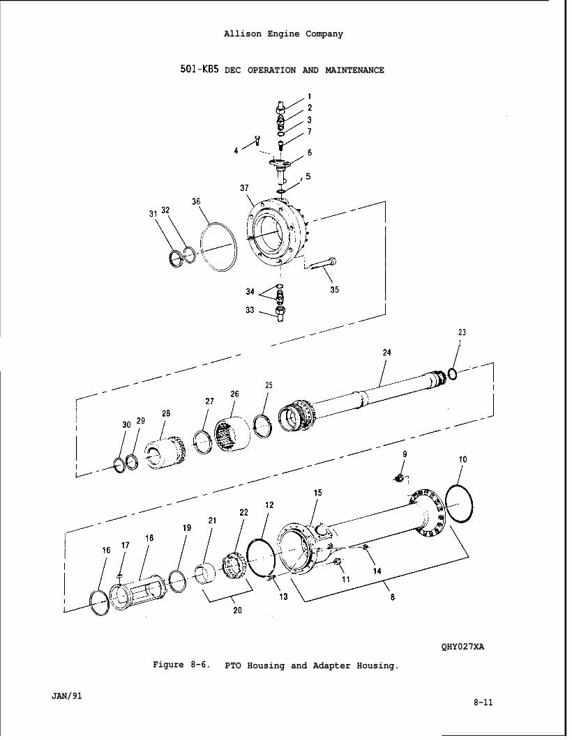
Allison Engine Company
501-KB5 DEC OPERATION AND MAINTENANCE
.
l’~ ,5,,
// 23// I
25
./
QHY027XA
Figure 8-6. PTO Housing and Adapter Housing.
JAN/918-11
●
●
Allison Engine Company
501-KB5 DEC OPERATION AND MAINTENANCE
NOTE
The midbearing’s inner race will remain with the PTO shaft when thePTO housing is removed. The midbearing guide, 6797753, is required toprotect the midbearing’s rollers during PTO housing removal and holdsthe midbearing’s rollers in place during PTO housing installation.
The roller retainer, 6797881, is used to hold the midbearing’srollers in place until the PTO housing is installed and/or themidbearing has to be replaced.
D. Make sure knurl knob scribe line is placed to LOAD, slide midbearingguide tool, 6797753, over the end of PTO shaft and hold in place byturning knurl knob scribe line to LOCK (Ref. Figure 8-7).
E, Remove nuts (11) and carefully remove PTO housing (8) keeping itcentered on the PTO shaft (24).
F, When PTO housing (8) is removed, install roller retainer tool,6797881, in the midbearing’s roller (Ref. Figure 8-8). Remove anddiscard O-rings (10 and 12).
G. If required, remove bolts (13), nuts (14), and pickup block assembly(15) from PTO housing (8).
H. If required, remove retaining ring (16), lock key (17), bearing locktube (18), and retaining ring (19).
CAUTION
DO NOT REMOVE OUTER RACE, ROLLERS, AND SEPARATOR UNLESS BEARINGASSEMBLY IS DAMAGED.
CAUTION
THE OUTER RACE, INNER RACE, ROLLERS, AND SEPARATOR IS A SERIALIZED SETAND CANNOT BE CHANGED INDIVIDUALLY. A COMPLETE BEARING ASSEMBLY MUSTCHANGE IF ANY DAMAGE HAS OCCURRED TO THE BEARING ASSEMBLY’S COMPONENTS.REFER TO PARAGRAPH 8-17.
1. If required, remove outer race, rollers, and separator (22) from PTOhousing (8).
8-12 JAN/91
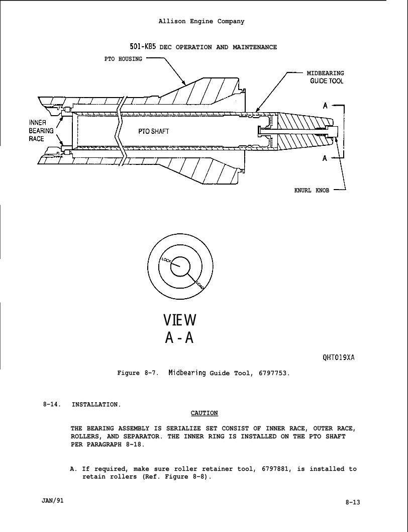
Allison Engine Company
501-KB5 DEC OPERATION AND MAINTENANCE
PTO HOUSING
7 ~ MIDBEARING
A
KNURL KNOBJ
@
%y
VIEWA - A
QHT019XA
Figure 8-7. Midbearing Guide Tool, 6797753.
8-14. INSTALLATION.CAUTION
THE BEARING ASSEMBLY IS SERIALIZE SET CONSIST OF INNER RACE, OUTER RACE,ROLLERS, AND SEPARATOR. THE INNER RING IS INSTALLED ON THE PTO SHAFTPER PARAGRAPH 8-18.
A. If required, make sure roller retainer tool, 6797881, is installed toretain rollers (Ref. Figure 8-8).
JAN/91 8-13
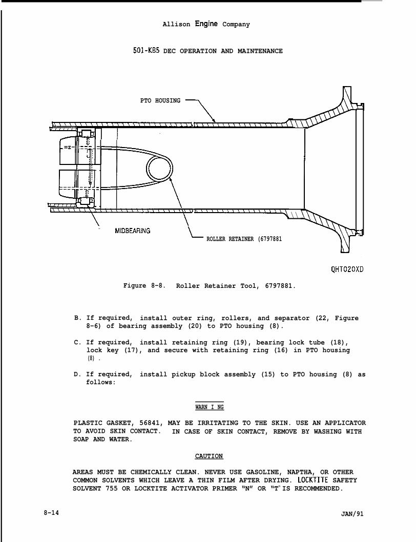
Allison Engine Company
501-KB5 DEC OPERATION AND MAINTENANCE
PTO HOUSING -
\\
=z- ,=--,
I
=
\\- NIDBEARING L ROLLER RETAINER (6797881
QHT020XD
Figure 8-8. Roller Retainer Tool, 6797881.
B. If required, install outer ring, rollers, and separator (22, Figure8-6) of bearing assembly (20) to PTO housing (8).
C. If required, install retaining ring (19), bearing lock tube (18),lock key (17), and secure with retaining ring (16) in PTO housing(8) .
D. If required, install pickup block assembly (15) to PTO housing (8) asfollows:
WARN I NG
PLASTIC GASKET, 56841, MAY BE IRRITATING TO THE SKIN. USE AN APPLICATORTO AVOID SKIN CONTACT. IN CASE OF SKIN CONTACT, REMOVE BY WASHING WITHSOAP AND WATER.
CAUTION
AREAS MUST BE CHEMICALLY CLEAN. NEVER USE GASOLINE, NAPTHA, OR OTHERCOMMON SOLVENTS WHICH LEAVE A THIN FILM AFTER DRYING. LOCKTITE SAFETYSOLVENT 755 OR LOCKTITE ACTIVATOR PRIMER “N” OR “Tn IS RECOMMENDED.
8-14 JAN/91
Allison Engine Company
501-KB5 DEC OPERATION AND MAINTENANCE
1. Clean pickup block assembly (15) and PTO housing (8) contactingareas with Locktite safety solvent, 755, or Locktite activatorprimer “N” or “T” per manufacturer instructions.
NOTE
Step 2. and 3. are done as one continue step.
2. Apply plastic gasket, 56841 (obtain from Pressure Cure Sealant -Locktite Corp., Newington, CN 06111) to pickup block assembly(15) and PTO housing (8) bolt holes and contacting surfaces, andthreads and bolt’s head underside of bolts (13).
3. Install pickup block assembly (15) to PTO housing (8) and securewith bolts (13) and nuts (14). Torque nuts to 180-200 lb in.(20.3 -22.5 Nom).
4. After assembling, excessive plastic gasket may be removed withchlorinated solvents or Locktite safety solvent, 755.
5. After curing of plastic gasket, retorque nuts (14) to valve usedin Step 3.
E. Make sure midbearing guide tool, 6797753, is installed on PTO shaft(24) (Ref. Figure 8-7).
CAUTION
THE MIDBEARING GUIDE TOOL, 6797753 WILL CONTACT THE ROLLER RETAINERTOOL, 6797881, WHEN THE PTO HOUSING IS APPROXIMATELY ONE-THIRDINSTALLED. A SLIGHT BUMPING MOTION WILL BE REQUIRED FOR THE MIDBEARINGGUIDE TOOL TO PUSH THE ROLLER RETAINER TOOL OUT OF THE BEARING. WHENTHE PTO HOUSING IS APPROXIMATELY TWO-THIRDS (2/3) INSTALLED, BEESPECIALLY CAREFUL TO KEEP THE PTO HOUSING CENTERED SO THAT THE BEARINGLOCK TUBE ID DOES NOT RUB AND/OR DAMAGE THE BEARING INNER RACE.
F.
G.
JAN/91
NOTE
Wet O-rings with clean engine oil.
Install O-ring (12, Figure 8-6) to PTO housing (8) and carefullyinstall PTO housing, keeping the PTO housing centered, overmidbearing guide tool and PTO shaft (24) and secure to adapterhousing (37) with pickup block assembly up and with nuts (11),Torque nuts to 160-190 lb in. (18.1-21.4 N-m).
Remove midbearing guide tool. Remove and install new O-ring (23) toPTO staff (24). Install O-ring (10) to PTO housing (8).
8-15
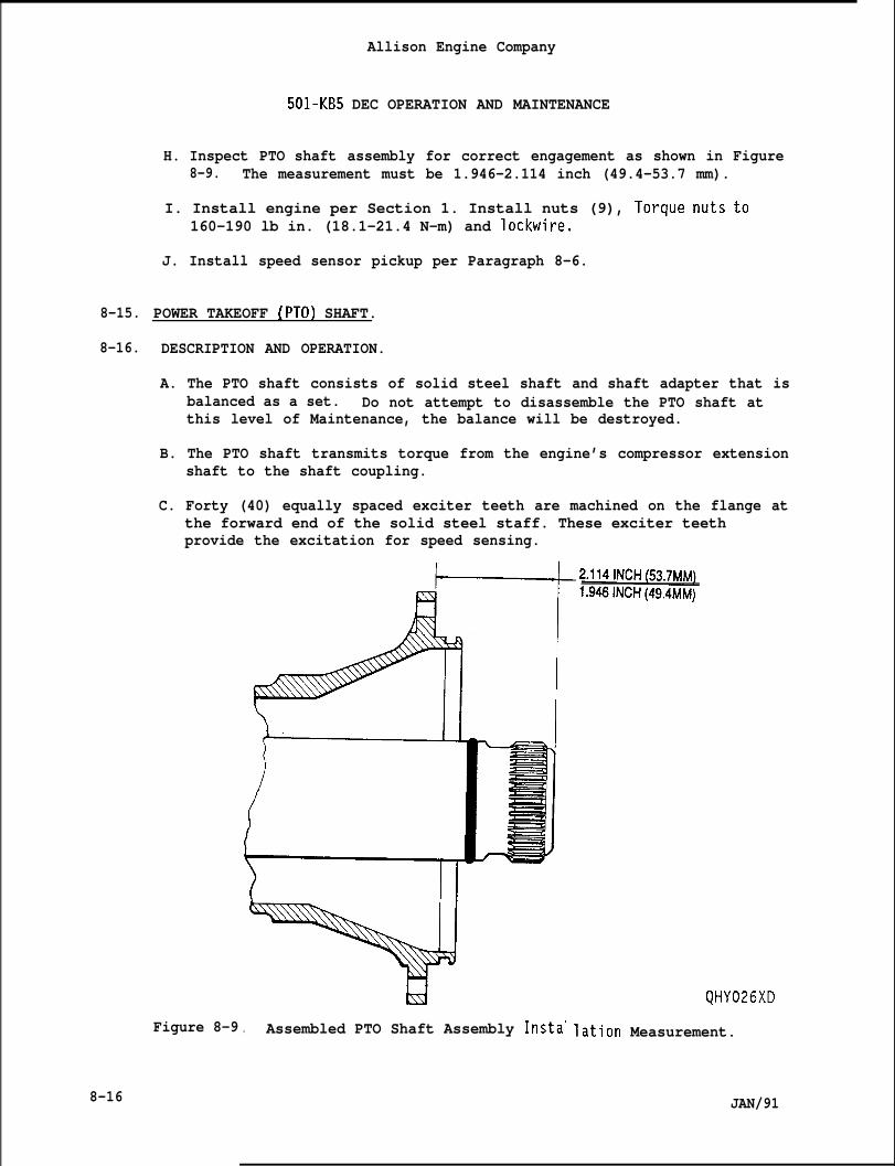
8-15.
8-16.
8-16
Allison Engine Company
501-KB5 DEC OPERATION AND MAINTENANCE
H. Inspect PTO shaft assembly for correct engagement as shown in Figure8-9. The measurement must be 1.946-2.114 inch (49.4-53.7 mm).
I. Install engine per Section 1. Install nuts (9), Torque nuts to160-190 lb in. (18.1-21.4 N-m) and lockwire.
J. Install speed sensor pickup per Paragraph 8-6.
POWER TAKEOFF [PTO) SHAFT.
DESCRIPTION AND OPERATION.
A. The PTO shaft consists of solid steel shaft and shaft adapter that isbalanced as a set. Do not attempt to disassemble the PTO shaft atthis level of Maintenance, the balance will be destroyed.
B. The PTO shaft transmits torque from the engine’s compressor extensionshaft to the shaft coupling.
C. Forty (40) equally spaced exciter teeth are machined on the flange atthe forward end of the solid steel staff. These exciter teethprovide the excitation for speed sensing.
la I
Figure 8-9
td. Assembled PTO Shaft Assembly Insta’
QHY026XD
lation Measurement.
JAN/91
Allison Engine Company
501-KB5 DEC OPERATION AND MAINTENANCE
8-17. REMOVAL .
A. Remove PTO housing (8, Figure 8-6) per Paragraph 8-13.
B. Remove aft retaining ring (25) and PTO shaft (24) from shaft coupling(26).
CAUTION
DO NOT REMOVE SHAFT ADAPTER FROM SOLID STEEL SHAFT. THE SHAFT ADAPTERAND SOLID STEEL ARE A BALANCED ASSEMBLY AND MUST REMAIN BOLTED TOGETHER.
C. If required, remove inner race (21) from PTO shaft (24) using bearingpulling fixture, 6797754, turn tee handle to push off inner race(Ref. Figure 8-10). Inspect PTO shaft for damage.
8-18. INSTALLATION.
CAUTION
THE PTO SHAFT IS A BALANCED ASSEMBLY,ADAPTER MUST REMAIN BOLTED TOGETHER.BE
A.
B.
c.
D.
THE SOLID STEEL SHAFT AND SHAFTIF SEPARATED, THE PTO SHAFT MUST
RETURNED TO A MAJOR REPAIR CENTER FOR BALANCING.
If required, press inner race (21, Figure 8-6) onto PTO shaft (24)using bearing inner race pusher, 6797756 (Ref. Figure 8-11) to seatinner race on PTO shaft.
Thread retaining ring (25, Figure 8-6) on the forward end of theshaft adapter of the PTO shaft (24).
Install forward external splines of the PTO shaft (24) to theinternal splines of the shaft coupling (26) and secure with retainingring (25).
Install PTO housing per Paragraph 8-14.
8-19. ADAPTER HOUSING.
8-20. DESCRIPTION AND OPERATION.
A. The adapter housing provides mounting of the PTO housing and enclosesthe shaft coupling and taper coupling.
B. The adapter housing provides mounting of the oil nozzle and drainhose.
JAN/91 8-17
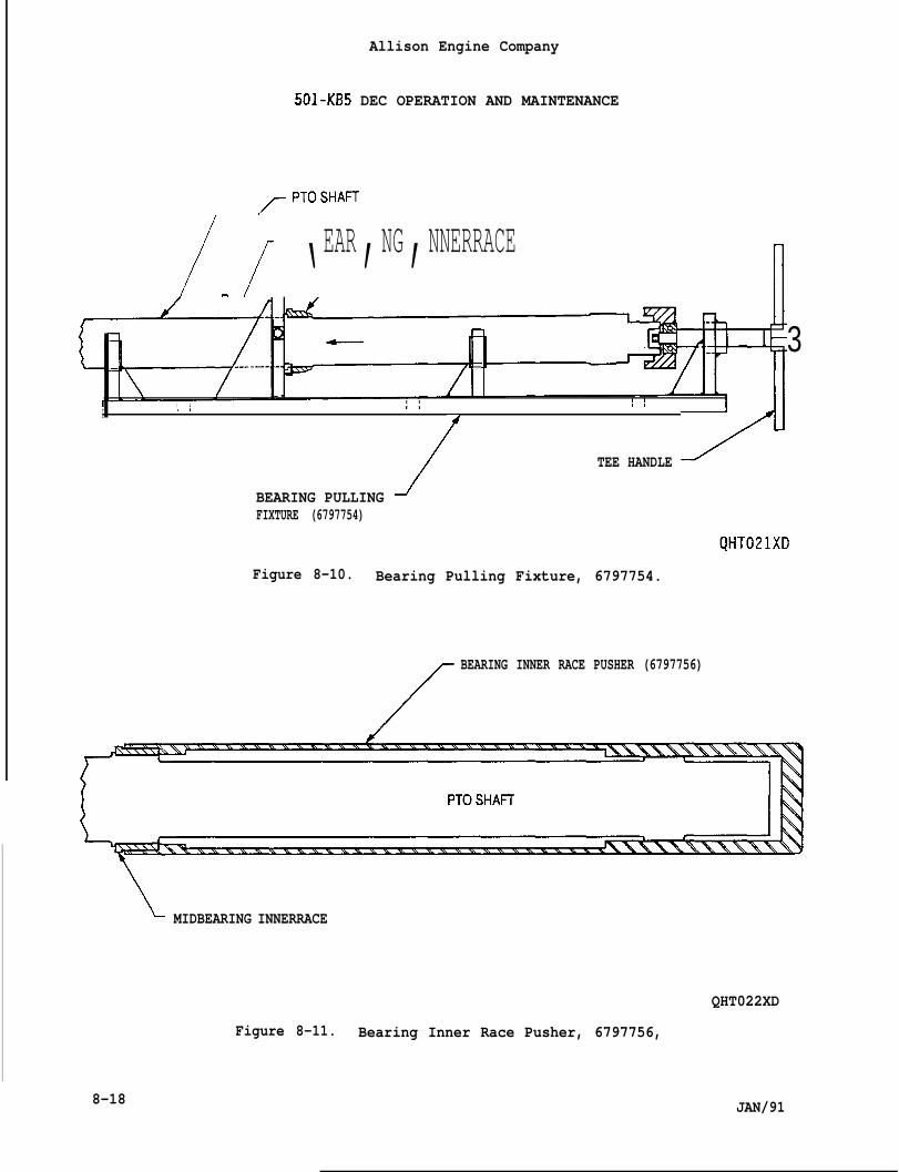
Allison Engine Company
501-KB5 DEC OPERATION AND MAINTENANCE
/-f ‘EAR’NG’NNERRACE
I ,, ,, I/
/TEE HANDLE/
3
BEARING PULLING JFIXTURE (6797754)
Figure 8-10. Bearing Pulling Fixture, 6797754.
/
BEARING INNER RACE PUSHER (6797756)
/
~ MIDBEARING INNERRACE
QHT022XD
Figure 8-11. Bearing Inner Race Pusher, 6797756,
8-18 JAN/91
I
Allison Engine Company
501-KB5 DEC OPERATION AND MAINTENANCE
8-21. REMOVAL .
A. Remove PTO shaft (24, Figure 8-6) per Paragraph 8-17.
B. Remove oil nozzle (6) per Paragraph 8-9.
C. Remove drain hose (33) from union (34).
D. Remove bolts (35) and adapter housing (37) from driven equipment.Remove and discard O-ring (36).
E. If required, remove union and O-ring (34). Discard O-ring.
8-22. INSTALLATION.
NOTE
Het O-rings with clean engine oil.
A. If required, install O-ring on union (34, Figure 8-6) and installunion and O-ring into housing adapter (37). Torque union to 50-70 lbft. (67.8-94.9 Nom).
B. Install O-ring (36) to adapter housing (37).
C. Install adapter housing (37) to driven equipment and secure withbolts (35). Torque bolts to 400-470 lb in. (45.2-53.1 Nom).Lockwire bolts.
D. Install drain hose (33) to union (34) and torque hose’s coupling nutas outlined in Section 15, General Maintenance.
E. Install oil nozzle per Paragraph 8-10.
F. Install PTO shaft (24) per Paragraph 8-18.
8-23. SHAFT AND TAPERED COUPLINGS.
8-24. DESCRIPTION AND OPERATION.
A. The shaft coupling is splined internal tocoupling and retained by an internal reta.
PTO shaft and to taperedning ring on each end.
B. The tapered coupling is pressure pumped on the driven shaft of thedriven equipment to provide connection of the PTO assembly to thedriven equipment.
C. The shaft and tapered couplings transmit the PTO shaft’s torque tothe driven equipment.
JAN/91 8-19
Allison Engine Company
501 -KB5 DEC OPERATION AND MAINTENANCE
8-25. REMOVAL .
A.
B.
c.
Remove adapter housing (37, Figure 8-6) per Paragraph 8-21.
Remove retaining ring (27) and shaft coupling (26) from taperedcoupling (28).
Remove tapered coupling (28) as follows:
1. Make sure O-ring (1, Figure 8-12) is serviceable and installed instud (2).
2. Install stud (2) in the threaded portion of input shaft (6, Figure.-.8-13).
NOTE
Make sure bearing races (5, Figure 8-12) and bearing (6) are properlyinstalled in the nut (7) and sleeve(3).
3. Install sleeve (3, Figure 8-12), bearing assembly (4), and nuton stud (2). Position nut until sleeve is approximately 0.125(1/8) inch (3.2 mm) from taper coupling (3, Figure 8-13).
4. Install elbow (8) in end of stud (2) while retaining stud frommoving, torque elbow per Section 15, General Maintenance.
7)
5. Connect tube (9) to elbow (8) and to pump and gage assembly (10).Torque tube’s coupling nuts per Section 15, General Maintenance.
NOTE
If required, service and bleed main drive coupling tool, 6798754, byloosening tube’s coupling nut at elbow and slowly activating the pumpand gage assembly until air free oil leaves connection. Torque tube’scoupling nut per Section 14, General Maintenance.
6. Build up pressure with pump and gage assembly (10) until taperedcoupling (3, Figure 8-13) moves in contact with the sleeve (3,Figure 8-12). Back off nut (7) while retaining stud (2) fromturning and continue building up pressure until tapered coupling(3, Figure 8-13) is free of driven equipment input shaft (6).
7. Remove tube (9, Figure 8-12) from elbow (8).
8. Remove remaining coupling tools and tapered coupling (3, Figure8-13) by removing (screw out) stud (2, Figure 8-12) and removingsleeve (3), bearing assembly (4), nut (7), and elbow (8).
8-20 JAN/91
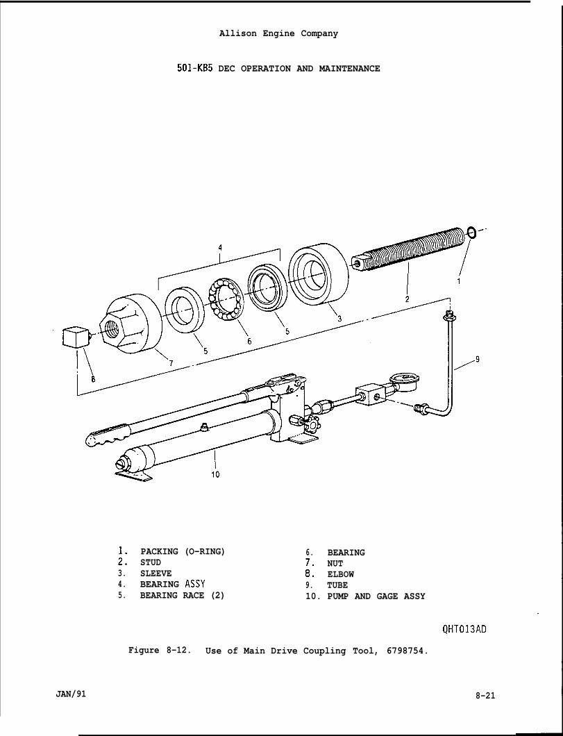
Allison Engine Company
501-KB5 DEC OPERATION AND MAINTENANCE
PACKING (O-RING);: STUD3. SLEEVE4. BEARING ASSY5. BEARING RACE (2)
6. BEARINGNUT
:: ELBOW9. TUBE10. PUMP AND GAGE ASSY
QHT013AD
Figure 8-12. Use of Main Drive Coupling Tool, 6798754.
JAN/91 8-21
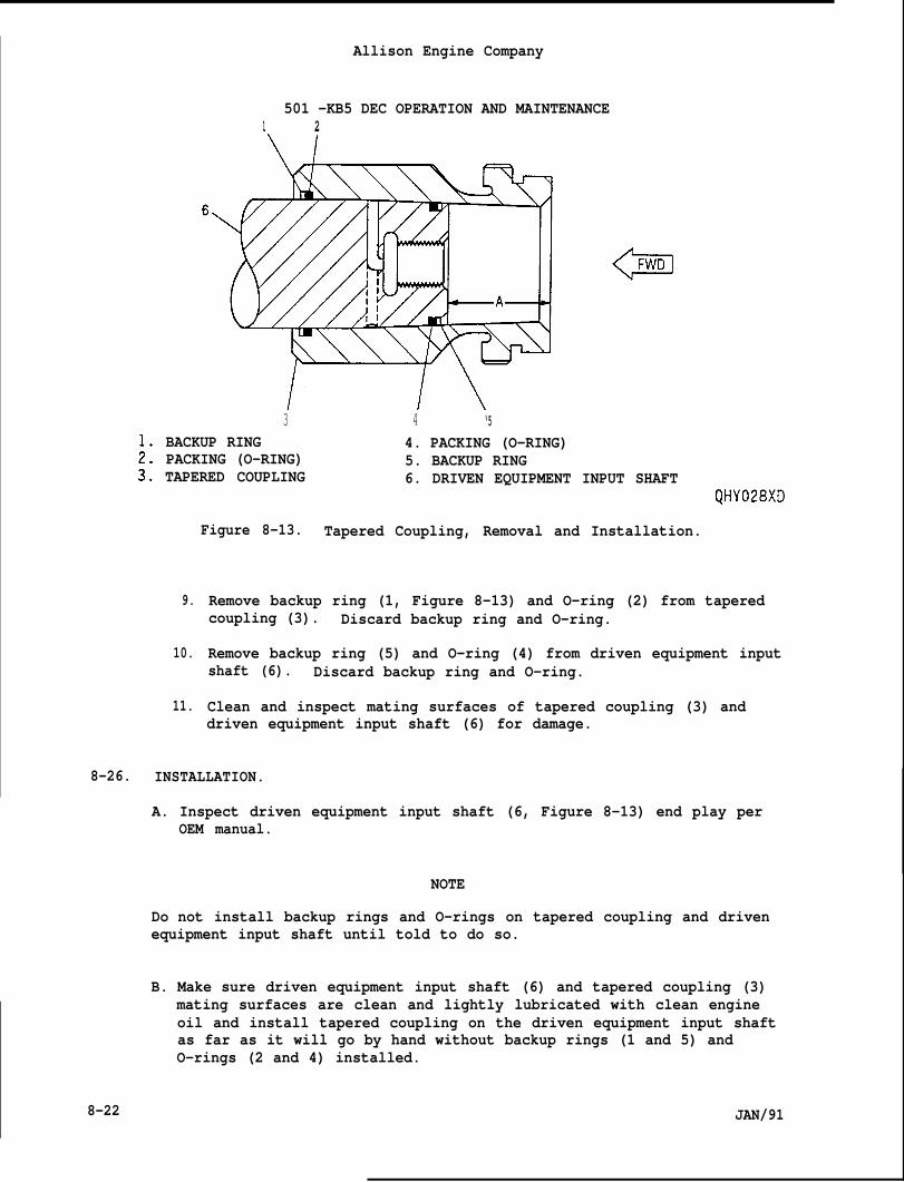
Allison Engine Company
501 -KB5 DEC OPERATION AND MAINTENANCE1 2
3BACKUP RINGPACKING (O-RING)TAPERED COUPLING
4 ‘54. PACKING (O-RING)5. BACKUP RING6. DRIVEN EQUIPMENT INPUT SHAFT
9.
10.
11.
QHY028XD
Figure 8-13. Tapered Coupling, Removal and Installation.
Remove backup ring (1, Figure 8-13) and O-ring (2) from taperedcoupling (3). Discard backup ring and O-ring.
Remove backup ring (5) and O-ring (4) from driven equipment inputshaft (6). Discard backup ring and O-ring.
Clean and inspect mating surfaces of tapered coupling (3) anddriven equipment input shaft (6) for damage.
8-26. INSTALLATION.
A. Inspect driven equipment input shaft (6, Figure 8-13) end play perOEM manual.
8-22
NOTE
Do not install backup rings and O-rings on tapered coupling and drivenequipment input shaft until told to do so.
B. Make sure driven equipment input shaft (6) and tapered coupling (3)mating surfaces are clean and lightly lubricated with clean engineoil and install tapered coupling on the driven equipment input shaftas far as it will go by hand without backup rings (1 and 5) andO-rings (2 and 4) installed.
JAN/91
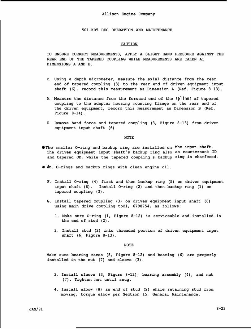
Allison Engine Company
501-KB5 DEC OPERATION AND MAINTENANCE
CAUTION
TO ENSURE CORRECT MEASUREMENTS, APPLY A SLIGHT HAND PRESSURE AGAINST THEREAR END OF THE TAPERED COUPLING WHILE MEASUREMENTS ARE TAKEN ATDIMENSIONS A AND B.
c.
D.
E.
Using a depth micrometer, measure the axial distance from the rearend of tapered coupling (3) to the rear end of driven equipment inputshaft (6), record this measurement as Dimension A (Ref. Figure 8-13).
Measure the distance from the forward end of the splines of taperedcoupling to the adapter housing mounting flange on the rear end ofthe driven equipment, record this measurement as Dimension B (Ref.Figure 8-14).
Remove hand force and tapered coupling (3, Figure 8-13) from drivenequipment input shaft (6).
NOTE
● The smaller O-ring and backup ring are installed onThe driven equipment input shaft’s backup ring alsoand tapered OD, while the tapered coupling’s backup
.Wet O-rings and backup rings with clean engine oil.
the input shaft.as countersunk IDring is chamfered.
F. Install O-ring (4) first and then backup ring (5) on driven equipmentinput shaft (6). Install O-ring (2) and then backup ring (1) ontapered coupling (3).
G. Install tapered coupling (3) on driven equipment input shaft (6)using main drive coupling tool, 6798754, as follows:
1. Make sure O-ring (1, Figure 8-12) is serviceable and installed inthe end of stud (2).
2. Install stud (2) into threaded portion of driven equipment inputshaft (6, Figure 8-13).
NOTE
Make sure bearing races (5, Figure 8-12) and bearing (6) are properlyinstalled in the nut (7) and sleeve (3).
3. Install sleeve (3, Figure 8-12), bearing assembly (4), and nut(7). Tighten nut until snug.
4. Install elbow (8) in end of stud (2) while retaining stud frommoving, torque elbow per Section 15, General Maintenance.
JAN/91 8-23
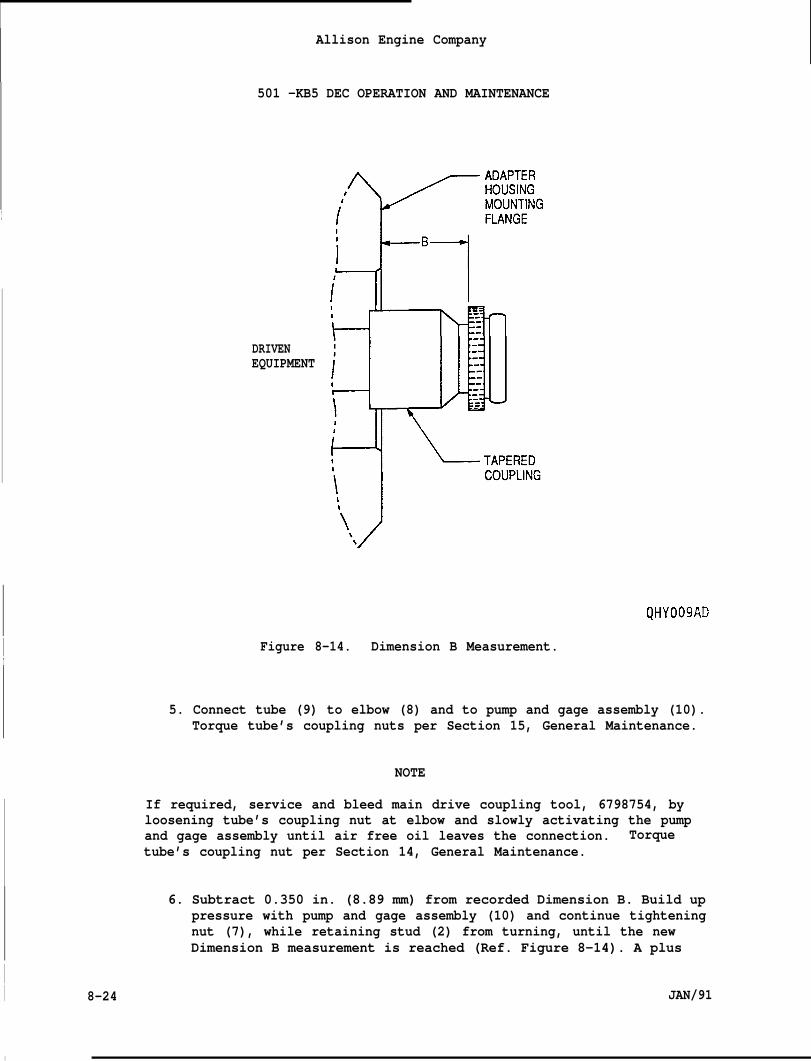
Allison Engine Company
501 -KB5 DEC OPERATION AND MAINTENANCE
I
DRIVENEQUIPMENT
QHYO09AD
I Figure 8-14. Dimension B Measurement.I
5. Connect tube (9) to elbow (8) and to pump and gage assembly (10).Torque tube’s coupling nuts per Section 15, General Maintenance.
NOTE
If required, service and bleed main drive coupling tool, 6798754, byloosening tube’s coupling nut at elbow and slowly activating the pumpand gage assembly until air free oil leaves the connection. Torquetube’s coupling nut per Section 14, General Maintenance.
6. Subtract 0.350 in. (8.89 mm) from recorded Dimension B. Build uppressure with pump and gage assembly (10) and continue tighteningnut (7), while retaining stud (2) from turning, until the newDimension B measurement is reached (Ref. Figure 8-14). A plus
II 8-24 JAN/91
I
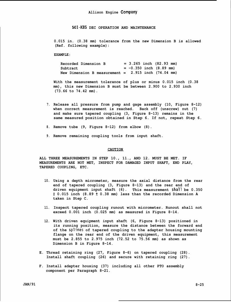
I
7.
8.
9.
Allison Engine Company
501-KB5 DEC OPERATION AND MAINTENANCE
0.015 in. (0.38 mm) tolerance from the new Dimension B is allowed(Ref. following example):
EXAMPLE:
Recorded Dimension B = 3.265 inch (82.93 mm)Subtract = -0.350 inch (8.89 mm)New Dimension B measurement = 2.915 inch (74.04 mm)
With the measurement tolerance of plus or minus 0.015 inch (0.38mm), this new Dimension B must be between 2.900 to 2.930 inch(73.66 to 74.42 mm).
Release all pressure from pump and gage assembly (10, Figure 8-12)when correct measurement is reached. Back off (unscrew) nut (7)and make sure tapered coupling (3, Figure 8-13) remains in thesame measured position obtained in Step 6. If not, repeat Step 6.
Remove tube (9, Figure 8-12) from elbow (8).
Remove remaining coupling tools from input shaft.
CAUTION
ALL THREE MEASUREMENTS IN STEP 10., 11., AND 12. MUST BE MET. IFMEASUREMENTS ARE NOT MET, INSPECT FOR DAMAGED INPUT SHAFT, END PLAY,TAPERED COUPLING, ETC.
10.
11.
12.
Using a depth micrometer, measure the axial distance from the rearend of tapered coupling (3, Figure 8-13) and the rear end ofdriven equipment input shaft (6). This measurement shall be 0.350t 0.015 inch (8.89 t 0.38 mm) less than the recorded Dimension Ataken in Step C.
Inspect tapered coupling runout with micrometer. Runout shall notexceed 0.001 inch (0.025 mm) as measured in Figure 8-14.
With driven equipment input shaft (6, Figure 8-13) positioned inits running position, measure the distance between the forward endof the splines of tapered coupling to the adapter housing mountingflange on the rear end of the driven equipment, this measurementmust be 2.855 to 2.975 inch (72.52 to 75.56 mm) as shown asDimension B in Figure 8-14.
E. Thread retaining ring (27, Figure 8-6) on tapered coupling (28).Install shaft coupling (26) and secure with retaining ring (27).
F. Install adapter housing (37) including all other PTO assemblycomponent per Paragraph 8-21.
JAN/91 8-25
Paraqraph
9-1
9-2
9-3
9-4
9-5
9-6
9-7
Fiqure No.
9-1
9-2
9-3
9-4
JAN/91
Allison Engine Company
501-KB5 DEC OPERATION AND MAINTENANCE
SECTION 9
ACCESSORY DRIVE GEARBOX
TABLE OF CONTENTS
Description
Description
Removal
Installation
Repairs
Liquid Fuel Pump Oil Seal Replacement
Magnetic Drain Plug and Chip Detector
Corrosion Treatment and Painting
INDEX TO FIGURES
Paqe No.
9-2
9-2
9-4
9-5
9-5
9-7
9-7
Accessory Drive Gearbox
Accessory Gearbox Drive Pads
Fuel Pump Drive Oil Seal Puller No. 6796461
Fuel Pump Drive Shaft Oil Seal Installation
Paqe No.
9-3
9-4
9-6
9-6
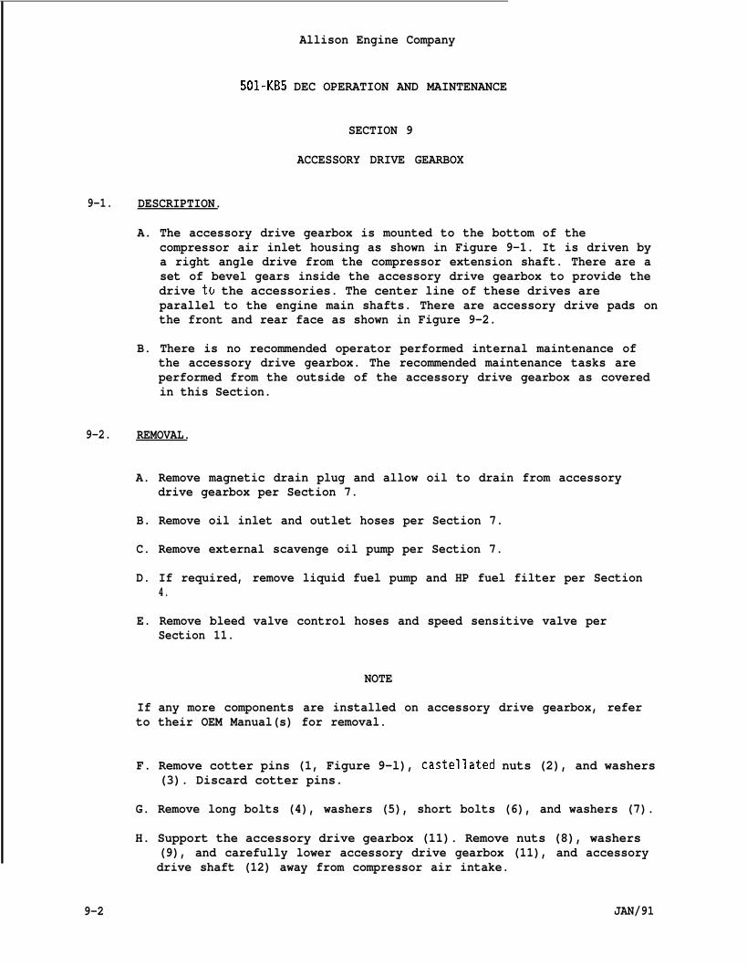
Allison Engine Company
501-KB5 DEC OPERATION AND MAINTENANCE
SECTION 9
ACCESSORY DRIVE GEARBOX
9-1. DESCRIPTION.
A. The accessory drive gearbox is mounted to the bottom of thecompressor air inlet housing as shown in Figure 9-1. It is driven bya right angle drive from the compressor extension shaft. There are aset of bevel gears inside the accessory drive gearbox to provide thedrive to the accessories. The center line of these drives areparallel to the engine main shafts. There are accessory drive pads onthe front and rear face as shown in Figure 9-2.
B. There is no recommended operator performed internal maintenance ofthe accessory drive gearbox. The recommended maintenance tasks areperformed from the outside of the accessory drive gearbox as coveredin this Section.
9-2. REMOVAL.
A. Remove magnetic drain plug and allow oil to drain from accessorydrive gearbox per Section 7.
B. Remove oil inlet and outlet hoses per Section 7.
C. Remove external scavenge oil pump per Section 7.
D. If required, remove liquid fuel pump and HP fuel filter per Section4.
E. Remove bleed valve control hoses and speed sensitive valve perSection 11.
NOTE
If any more components are installed on accessory drive gearbox, referto their OEM Manual(s) for removal.
F. Remove cotter pins (1, Figure 9-l), castellated nuts (2), and washers(3). Discard cotter pins.
G. Remove long bolts (4), washers (5), short bolts (6), and washers (7).
9-2
H. Support the accessory drive gearbox (11). Remove nuts (8), washers(9), and carefully lower accessory drive gearbox (11), and accessorydrive shaft (12) away from compressor air intake.
JAN/91
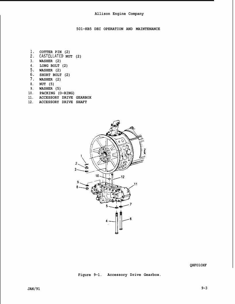
;:3.4.5.6.7,8.9.
10.11.12.
Allison Engine Company
501-KB5 DEC OPERATION AND MAINTENANCE
COTTER PIN (2)CASTELLATED NUT (2)WASHER (2)LONG BOLT (2)WASHER (2)SHORT BOLT (2)WASHER (2)NUT (5)WASHER (5)PACKING (O-RING)ACCESSORY DRIVE GEARBOXACCESSORY DRIVE SHAFT
QHFO1OXF
Figure 9-1. Accessory Drive Gearbox.
JAN/91 9-3
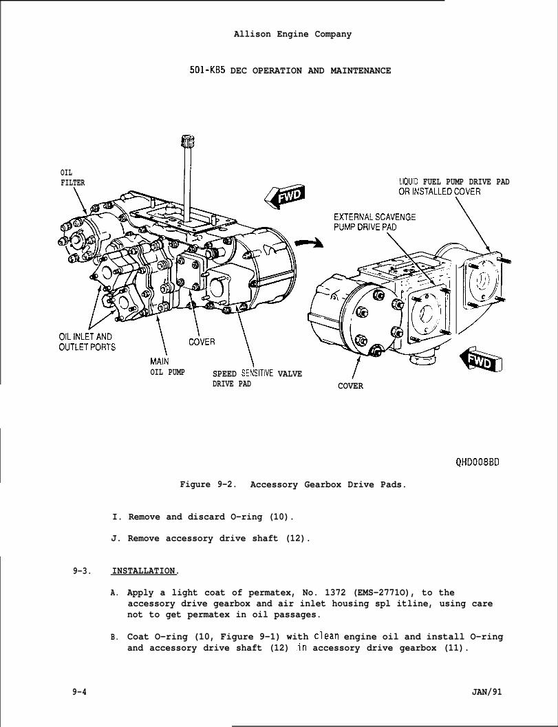
OILFILTER
Allison Engine Company
501-KB5 DEC OPERATION AND MAINTENANCE
LIQUID FUEL PUMP DRIVE PAD—
9-3.
9-4
OIL PUMP SPEED SEFklTIVE VALVE /DRIVE PAD COVER
A.
B.
/
*B
QHDO08BD
Figure 9-2. Accessory Gearbox Drive Pads.
I. Remove and discard O-ring (10).
J. Remove accessory drive shaft (12).
INSTALLATION.
Apply a light coat of permatex, No. 1372 (EMS-2771O), to theaccessory drive gearbox and air inlet housing spl itline, using carenot to get permatex in oil passages.
Coat O-ring (10, Figure 9-1) with clean engine oil and install O-ringand accessory drive shaft (12) .in accessory drive gearbox (11).
JAN/91
c.
D.
E.
F.
G.
H.
I.
J.
K.
L.
Allison Engine Company
501-KB5 DEC OPERATION AND MAINTENANCE
Install accessory drive gearbox (11) on bottom side of air inlethousing, align accessory drive shaft (12), if required, by slowlyturning accessory drive gearbox drive train. Secure with washers (9)and nuts (8). Support accessory drive gearbox and torque nuts to74-89 lb in. (8.4-10.0 N”m).
Install washers (5) and long bolts (4). Install washers (7) andshort bolts (6). Torque all bolts to 120-150 lb in. (13.6-16.9N-m). Lockwire bolts in pairs. Remove accessory drive gearboxsupport.
Install washers (3) and castellated nuts (2). Torquenuts to 70 lb in. (8.0 Nom), install cotter pins (l).pin holes do not align, torque castellated nuts untilalignment hole, but do not exceed 85 lb in. (9.6 N-m)
Install speed sensitive valve and bleed valve controlSection 11.
castellatedIf cotter
the nextof torque.
hoses per
If required, install liquid fuel and HP fuel filter per Section 4.
Install external scavenge oil pump per Section 7.
Install oil inlet and outlet hoses per Section 7.
If required, install any more components that were removed per theirOEM Manual.
Install magnetic drain and service engine per Section 7.
Perform an operation and leakage test.
9-4. REPAIR.
9-5. LIQUID FUEL PUMP DRIVE OIL SEAL REPLACEMENT.
A. Remove fuel pump and HP fuel filter per Section 4.
B. Insert threaded end of fuel pump drive oil seal puller (seal puller),6796461, in the seal center hole and tighten until threaded end isfirmly gripping seal (Ref. Figure 9-3).
C. Use the sliding hammer of seal puller and remove the seal.
D. Clean and inspect seal hole in accessory drive gearbox for damage.
E. Insert seal expander, 6796355, in fuel pump drive shaft (Ref. Figure9-4).
JAN/91 9-5
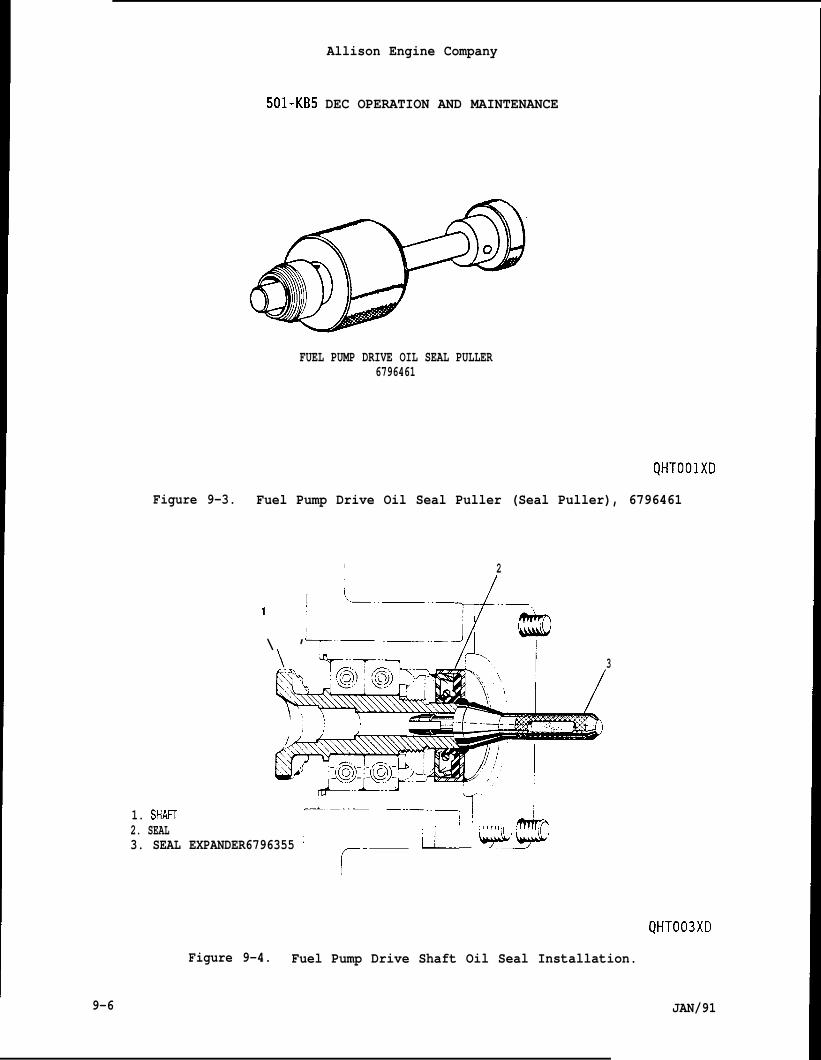
Allison Engine Company
501-KB5 DEC OPERATION AND MAINTENANCE
FUEL PUMP DRIVE OIL SEAL PULLER6796461
QHTOOIXD
Figure 9-3. Fuel Pump Drive Oil Seal Puller (Seal Puller), 6796461
I 2
I L..—..2..–1
\ ’+- “—’”–Y q3
1. SHA!7 ~..—.
2. SEAL–“”–””-- I
&,:
3. SEAL EXPANDER6796355 ; ji”~-
I
JAN/91
Figure 9-4. Fuel Pump Drive Shaft Oil Seal Installation.
9-6
F.
G.
H.
I.
501-KB5
Apply a light coatOD of the seal and
Ailison Engine Company
DEC OPERATION AND MAINTENANCE
of clean engine oil or a light grease to lip andto OD of seal expander, 6796355.
Install seal over the seal expander with the lip toward the accessorydrive gearbox,
Carefully drive and seat the seal into place, using a socket as adrift.
Install liquid fuel pump and HP fuel filter per Section 4.
9-6. MAGNETIC DRAIN PLUG AND CHIP DETECTOR.
A.
B.
c.
D.
E.
A magnetic drain plug (non-indicating) is located in the bottom ofthe accessory drive gearbox to collect magnetic particles from theoil system. This magnetic drain plug provides an oil system drainpoint.
The magnetic drain plug is inspected for accumulated material byremoving the magnetic drain plug. (Ref. Section 7, Engine LubricationSystem.)
A magnetic chip detector (indicating) is located in the main oil pumpscavenge outlet and monitors the oil flowing to the oil tank.
During engine operation metal particles may accumulate on themagnetic chip detector. When the contacts have a resistance of20,000 ohms or less, remove and inspect the magnetic chip detector.(Ref. to Section 7, Engine Lubrication System. )
The magnetic chip detector may be connected to an optional warninglight. The light will illuminate whenever metal particle accumula-tion is sufficient to establish electrical continuity in the alarmcircuit. When this occurs, proceed in accordance with Section 7,Engine Lubrication System,
9-7. CORROSION TREATMENT AND PAINTING.
NOTE
Exterior surface coatings of the accessory drive gearbox and cover thatare damaged and allow bare metal exposure shall be treated as follows:
A. Abrade the damaged area with emery cloth.
JAN/91 9-7
Allison Engine Company
501-KB5 DEC OPERATION AND MAINTENANCE
WARNING
THIS SOLUTION IS INJURIOUS TO THE SKIN AND CLOTHING: OPERATORS MUST BEADEQUATELY PROTECTED BY GOGGLES, RUBBER GLOVES, APRONS, ETC.
B. Swab area to be treated with clean water. While still wet, coat areawith the following aqueous solution using a nylon bristle brush:
Alodine No. 1200* 3 oz per galNitric Acid (HN03) 1/2 fluid oz per gal
* American Chemical Paint Co., Ambler, Pa.
C. Both part and solution must be maintained at room temperature. Allowsolution to remain on area from one to five minutes, but in no caseshould it be allowed to dry on the part.
D. Rinse or swab the coated area thoroughly with cleancompletely remove all remaining solution.
CAUTION
ALL BRUSHES AND SWABS MUST BE WATER RINSED TO MINIMIZE
E.
F.
G.
Blow surface dry with clean, dry air.
ADDIV Daint, consisting of a mixture, by volume, of
water to
FIRE HAZARD.
two partsA~ti~hane WC1OO (produ~t of Saren Chemical Co. ,Detroit, Michigan),and one part special lacquer reducer No. 9012 (product of Gliden CO.,Cleveland, Ohio).
Brush part with two coats; allow first coat to air dry for at least20 minutes. Localize heat cure after the second coat.
9-8 JAN/91
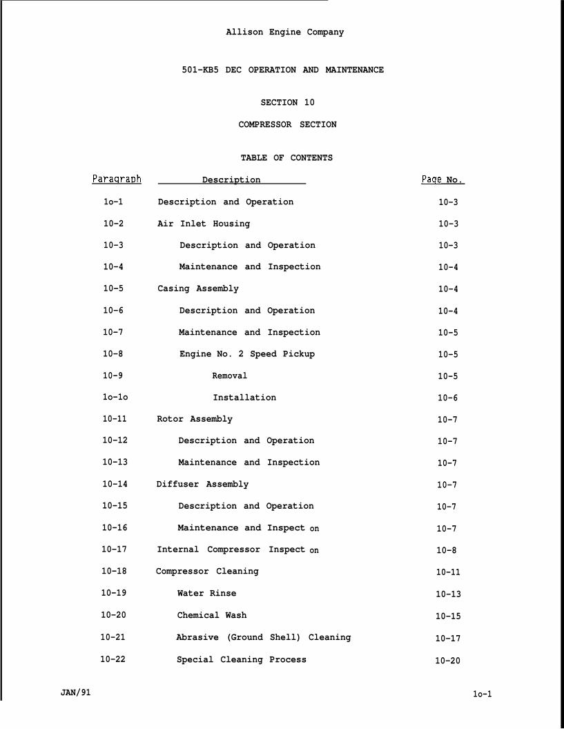
Paraqraph
1o-1
10-2
10-3
10-4
10-5
10-6
10-7
10-8
10-9
1o-1o
10-11
10-12
10-13
10-14
10-15
10-16
10-17
10-18
10-19
10-20
10-21
10-22
JAN/91
Allison Engine Company
501-KB5 DEC OPERATION AND MAINTENANCE
SECTION 10
COMPRESSOR SECTION
TABLE OF CONTENTS
Description
Description and Operation
Air Inlet Housing
Description and Operation
Maintenance and Inspection
Casing Assembly
Description and Operation
Maintenance and Inspection
Engine No. 2 Speed Pickup
Removal
Installation
Rotor Assembly
Description and Operation
Maintenance and Inspection
Diffuser Assembly
Description and Operation
Maintenance and Inspect
Internal Compressor Inspect
Compressor Cleaning
Water Rinse
Chemical Wash
on
on
Abrasive (Ground Shell) Cleaning
Special Cleaning Process
Paqe No.
10-3
10-3
10-3
10-4
10-4
10-4
10-5
10-5
10-5
10-6
10-7
10-7
10-7
10-7
10-7
10-7
10-8
10-11
10-13
10-15
10-17
10-20
1o-1
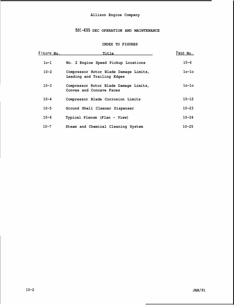
Allison Engine Company
501-KB5 DEC OPERATION AND MAINTENANCE
INDEX TO FIGURES
Fiqure No. Title
1o-1 No. 2 Engine Speed Pickup Locations
10-2 Compressor Rotor Blade Damage Limits,Leading and Trailing Edges
10-3 Compressor Rotor Blade Damage Limits,Convex and Concave Faces
10-4 Compressor Blade Corrosion Limits
10-5 Ground Shell Cleaner Dispenser
10-6 Typical Plenum (Plan - View)
10-7 Steam and Chemical Cleaning System
10-2
Paqe No.
10-6
1o-1o
1o-1o
10-12
10-23
10-24
10-25
JAN/91
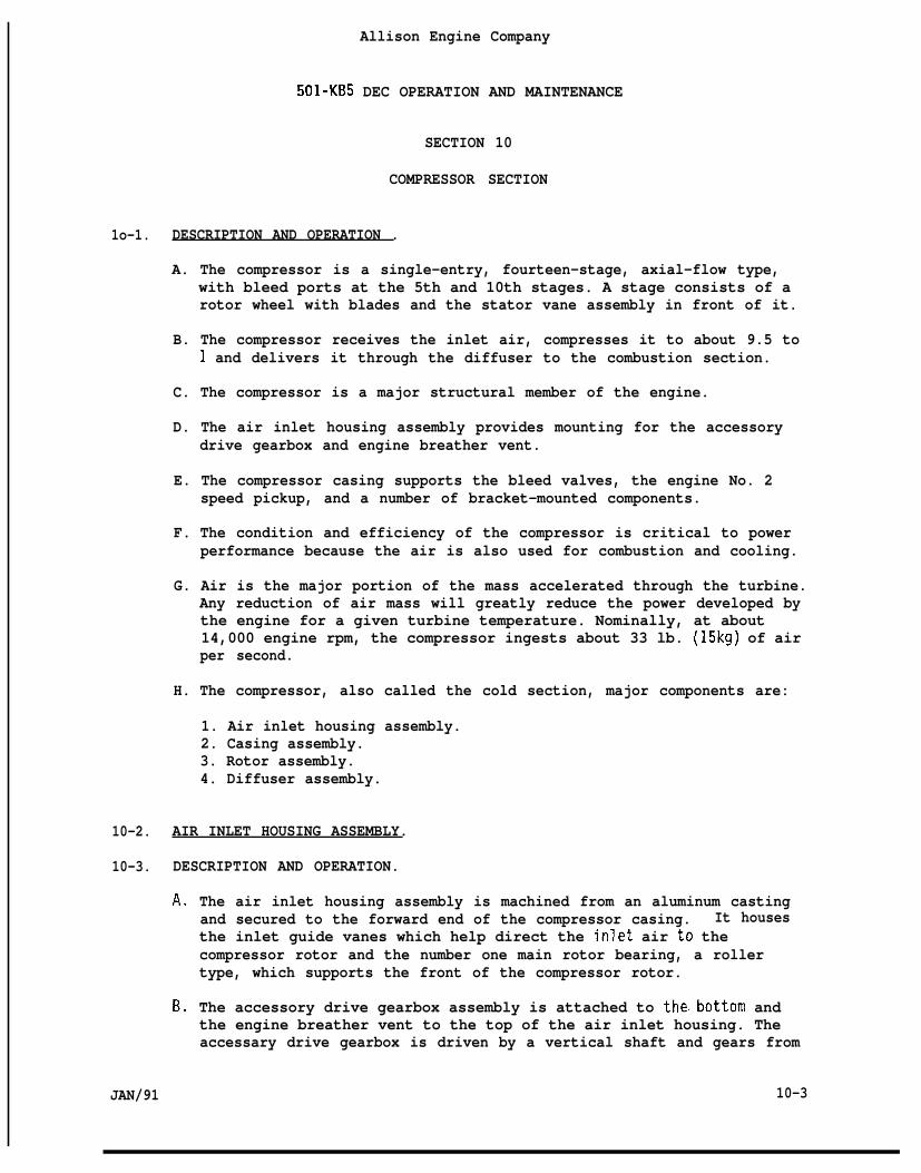
Allison Engine Company
501-KB5 DEC OPERATION AND MAINTENANCE
SECTION 10
COMPRESSOR SECTION
1o-1. DESCRIPTION AND OPERATION .
A. The compressor is a single-entry, fourteen-stage, axial-flow type,with bleed ports at the 5th and 10th stages. A stage consists of arotor wheel with blades and the stator vane assembly in front of it.
B. The compressor receives the inlet air, compresses it to about 9.5 to1 and delivers it through the diffuser to the combustion section.
C. The compressor is a major structural member of the engine.
D. The air inlet housing assembly provides mounting for the accessorydrive gearbox and engine breather vent.
E. The compressor casing supports the bleed valves, the engine No. 2speed pickup, and a number of bracket-mounted components.
F. The condition and efficiency of the compressor is critical to powerperformance because the air is also used for combustion and cooling.
G. Air is the major portion of the mass accelerated through the turbine.Any reduction of air mass will greatly reduce the power developed bythe engine for a given turbine temperature. Nominally, at about14,000 engine rpm, the compressor ingests about 33 lb. (15kg) of airper second.
H. The compressor, also called the cold section, major components are:
1. Air inlet housing assembly.2. Casing assembly.3. Rotor assembly.4. Diffuser assembly.
10-2. AIR INLET HOUSING ASSEMBLY.
10-3. DESCRIPTION AND OPERATION.
A.
B.
JAN/91
The air inlet housing assembly is machined from an aluminum castingand secured to the forward end of the compressor casing. It housesthe inlet guide vanes which help direct the inlet air to thecompressor rotor and the number one main rotor bearing, a rollertype, which supports the front of the compressor rotor.
The accessory drive gearbox assembly is attached to thebottom andthe engine breather vent to the top of the air inlet housing. Theaccessary drive gearbox is driven by a vertical shaft and gears from
10-3
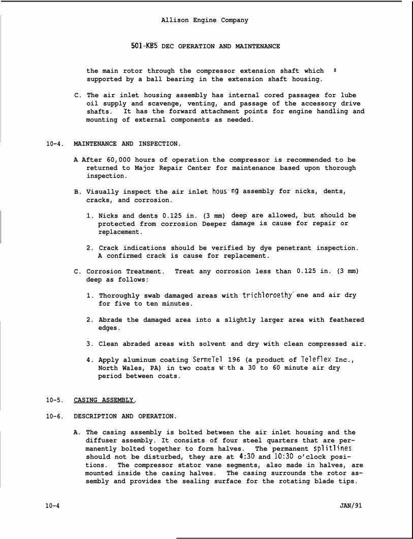
Allison Engine Company
501-KB5 DEC OPERATION AND MAINTENANCE
the main rotor through the compressor extension shaft whichsupported by a ball bearing in the extension shaft housing.
s
C. The air inlet housing assembly has internal cored passages for lubeoil supply and scavenge, venting, and passage of the accessory driveshafts. It has the forward attachment points for engine handling andmounting of external components as needed.
I 10-4. MAINTENANCE AND INSPECTION.
A After 60,000 hours of operation the compressor is recommended to bereturned to Major Repair Center for maintenance based upon thoroughinspection.
B. Visually inspect the air inlet hous”cracks, and corrosion.
1. Nicks and dents 0.125 in. (3 mm)protected from corrosion Deeperreplacement.
ng assembly for nicks, dents,
deep are allowed, but should bedamage is cause for repair or
2. Crack indications should be verified by dye penetrant inspection.A confirmed crack is cause for replacement.
C. Corrosion Treatment. Treat any corrosion less thandeep as follows:
1. Thoroughly swab damaged areas with trichloroethy”for five to ten minutes.
0.125 in. (3 mm)
ene and air dry
2. Abrade the damaged area into a slightly larger area with featherededges.
3. Clean abraded areas with solvent and dry with clean compressed air.
4. Apply aluminum coating SermeTelNorth Wales, PA) in two coats wperiod between coats.
10-5. CASING ASSEMBLY.
10-6. DESCRIPTION AND OPERATION.
196 (a product of Teleflex Inc.,th a 30 to 60 minute air dry
A. The casing assembly is bolted between the air inlet housing and thediffuser assembly. It consists of four steel quarters that are per-manently bolted together to form halves. The permanent splitlinesshould not be disturbed, they are at 4:30 and 10:30 o’clock posi-tions. The compressor stator vane segments, also made in halves, aremounted inside the casing halves. The casing surrounds the rotor as-sembly and provides the sealing surface for the rotating blade tips.
10-4 JAN/91
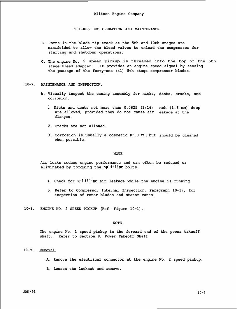
Allison Engine Company
501-KB5 DEC OPERATION AND MAINTENANCE
B. Ports in the blade tip track at the 5th and 10th stages aremanifolded to allow the bleed valves to unload the compressor forstarting and shutdown operations.
C. The engine No. 2 speed pickup is threaded into the top of the 5thstage bleed adapter. It provides an engine speed signal by sensingthe passage of the forty-one (41) 5th stage compressor blades.
10-7. MAINTENANCE AND INSPECTION.
A. Visually inspect the casing assembly for nicks,corrosion.
1. Nicks and dents not more than 0.0625 (1/16)are allowed, provided they do not cause airflanges.
2. Cracks are not allowed.
dents, cracks, and
nch (1.6 mm) deepeakage at the
3. Corrosion is usually a cosmetic ~roblem, but should be cleanedwhen possible.
NOTE
Air leaks reduce engine performance and can often be reduced oreliminated by torquing the splitline bolts.
4. Check for spl itline air leakage while the engine is running.
5. Refer to Compressor Internal Inspection, Paragraph 10-17, forinspection of rotor blades and stator vanes.
10-8. ENGINE NO. 2 SPEED PICKUP (Ref. Figure 10-1).
NOTE
The engine No. 1 speed pickup in the forward end of the power takeoffshaft. Refer to Section 8, Power Takeoff Shaft.
10-9. Removal.
A. Remove the electrical connector at the engine No. 2 speed pickup.
B. Loosen the locknut and remove.
JAN/91 10-5
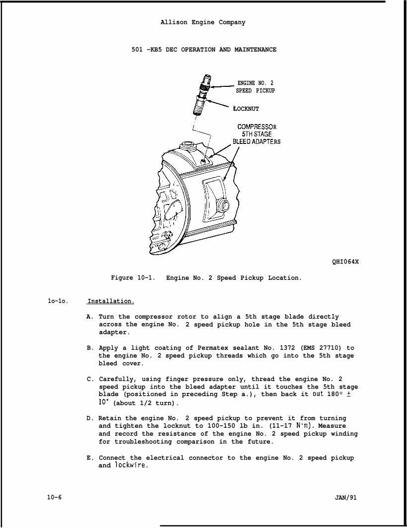
Allison Engine Company
501 -KB5 DEC OPERATION AND MAINTENANCE
F ENGINE NO. 2SPEED PICKUP
LOCKNUT
R
RS
QHI064X
Figure 10-1. Engine No. 2 Speed Pickup Location.
1o-1o. Installation.
A. Turn the compressor rotor to align a 5th stage blade directlyacross the engine No. 2 speed pickup hole in the 5th stage bleedadapter.
B. Apply a light coating of Permatex sealant No. 1372 (EMS 27710) tothe engine No. 2 speed pickup threads which go into the 5th stagebleed cover.
C. Carefully, using finger pressure only, thread the engine No. 2speed pickup into the bleed adapter until it touches the 5th stageblade (positioned in preceding Step a.), then back it Out 180° t10” (about 1/2 turn).
D. Retain the engine No. 2 speed pickup to prevent it from turningand tighten the locknut to 100-150 lb in. (11-17 Nom). Measureand record the resistance of the engine No. 2 speed pickup windingfor troubleshooting comparison in the future.
E. Connect the electrical connector to the engine No. 2 speed pickupand lockwire.
10-6 JAN/91
1
10-11.
10-12.
A.
B.
10-13.
Allison Engine Company
501-KB5 DEC OPERATION AND MAINTENANCE
ROTOR ASSEMBLY.
DESCRIPTION AND OPERATION.
The rotor assembly is made of fourteen bladed wheels stacked togetherand held by a single tie bolt through the center. The wheels areprogressively larger in diameter with progressively shorter bladesfrom front (lst stage) to rear (14th stage). A stub shaft on the 1ststage wheel supports the front of the rotor by a roller bearing inthe air inlet housing. A stub shaft on the 14th stage wheel supportsthe rear of the rotor by a ball (thrust) bearing in the diffuserassembly. The rotor assembly is driven by the engine turbine shaftthrough splines on the 14th stage wheel stub shaft.
The purpose of the rotor assembly is to use the energy provided by theengine turbine to compress the air. It also transmits power from theturbine to the compressor extension shaft in the air inlet housing todrive the accessory drive gearboxe and power takeoff assembly.
MAINTENANCE AND INSPECTION.
NOTE
Refer to Internal Compressor Inspection, Paragraph 10-17, forinspection of rotor blades and stator vanes.
10-14. DIFFUSER ASSEMBLY.
10-15. DESCRIPTION AND OPERATION.
A. The diffuser assembly is a welded steel fabrication that serves asthe primary mounting and support of the engine. It is securedbetween the rear of the compressor casing assembly and the front ofthe outer combustion case. The No. 3 main bearing (ball type), whichreacts all engine rotor thrust loads, is supported by the diffuserassembly. The diffuser assembly also provides mounting for the sixfuel nozzles.
B. The primary purpose of the diffuser assembly is to direct the airfrom the compressor rotor to the combustion section while reducingthe velocity of the air.
10-16. MAINTENANCE AND INSPECTION.
A. Check for splitline and 14th stage b“engine is running. Air leaks reducebe reduced or eliminated by torquingbleed port gaskets.
JAN/91
eed port air leakage while theengine performance and can oftenthe splitline bolts or replacing
10-7
B.
10-17.
A.
B.
Allison Engine Company
501-KB5 DEC OPERATION AND MAINTENANCE
Fuel nozzle gaskets and retaining bolt torque should also be checkedas a source of air leakage.
INTERNAL COMPRESSOR INSPECTION.
The condition of the compressor flow path is a major factor of enginehealth. Any condition that reduces compressor efficiency will causea reduction of engine performance. Conditions that reduce compressorefficiency include:
1. Contamination.2. Corrosion.3. Mechanical damage.4. Erosion.5. Leakage.6. Inlet flow restrictions (partial blockage).7. External inlet air ducting design and pressure drop.8. Exhaust system backpressure.
Inspections and maintenance should be performed as necessary todetect and correct or minimize these conditions.
WARNING
KEEP HANDS OUT OF THE ENGINE. DO NOT TURN THE ENGINE ROTOR BY THEBLADES. DISABLE STARTER CIRCUITS DURING INSPECTION. SEVERE INJURY MAYOCCUR.
C. Inspection access to an installed engine is limited. The primaryinspection access is the engine air inlet. A thorough inspection ofthe air inlet guide vane assembly and the 1st stage rotor blades canbe done. Portions of the 1st stage stator vanes, 2nd stage rotorblades and 2nd stage stator vanes can be seen.
D. Local inspection of 4th stage vane trailing edges, 5th stage vaneleading edges, and complete inspection of the 5th stage rotor bladesis accomplished by removing the bleed valve at one or more of the 5thstage bleed adapters. Similarly, the 9th, and 10th stages areinspected through one or more of the 10th stage bleed valve ports.Usually, inspection through these bleed valve ports is more revealingof contamination, FOD, erosion, and corrosion than an inletinspection, because the condition is more concentrated in thesesmaller areas.
NOTE
The engine rotor may be turned manually for inspection using an adapterto turn the accessary drive gearbox or the driven equipment
E. Inspect for contamination: dirt, scale, oil, and residues. To cleanthe compressor, refer to compressor cleaning, Paragraph 10-18.
10-8 JAN/91
Allison Engine Company
501-KB5 DEC OPERATION AND MAINTENANCE
WARNING
THE TEMPERATURE RISE THROUGH THE COMPRESSOR CAN BE(260”C). SEVERE BURNS CAN OCCUR.
F. Inspect for air leaks. While the engine is runribleed adapters and manifolds for air leakage. Rt
MORE THAN 500”F
ng, check splitlines,pair as necessary.
G. Evidence that indicates the engine has operated with air inletblockage or partial blockage for more than 5 minutes is cause forengine removal for major repair.
1. Blockage, or partial blockage, of the engine air inlet at the airinlet housing or the air inlet guide vanes causes a harmonicexcitation of some compressor blade stages which can quicklyreduce blade strength and life due to high cycle fatigue.
2. Blockage is considered to be material found to cover the area oftwo or more air inlet guide vanes or sufficient to cause anoticeable reduction of power.
H. InsDect for mechanical damage: evidence of foreign object damage(FOD), cracks,Remove the eng”seen.
nicks, dents; bent, or otherwise damaged parts.ne for repair if any of the following condt ions
NOTE
Damaaed vanes or blades exceeding inspection limits may be onlyreworked or replaced during engi~e major repair.
1.
2.
3.
4.
5.
6.
Any missing, cracked, or broken stator vane or rotor blade.
Any rotor blade with a nick, or dent in a blade, in the areathe base to 1/3 of the distance to the tip, if the damage isenough to feel.
Any rotor blade with damage in the outer 2/3 of blade lengththe damage exceeds the limits shown in Figure 10-2 and 10-3.Sharp nicks or dents are not allowed.
are
fromdeep
and
Any rotor blade bent enough to make contact with a stator vane.
Damage to ten or more stator vanes orstage.
Any rotor blade with corrosion exceed”Figure 10-4.
rotor blades in the 1st
ng the limits shown in
JAN/91 10-9
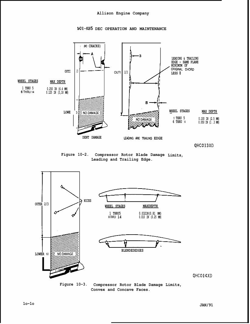
OUTI
WHEEL STAGES MAX DEPTH1 THRU 5 0.250 IN (6.4 MM)6THRU14 0.125 IN (3,18 MM)
LOWE
rOUTER 2/3
1LOWER 1/3
L
Allison Engine Company
bO1-KB5 DEC OPERATION AND MAINTENANCE
I (NO CRACKS)I
?wLA
/3 ———- OUTI
)-1 B/ I LEADING & TRAILING
EDGE - SAME PLANE
I--#MINIMUM OFoRiGtNAL CHORD
2/3 LESS B
I ;
DENT DAMAGE tiING At4D TRAtLING EDGE
Figure 10-2. Compressor Rotor Blade DamageLeading and Trailing Edge.
\
0+/ NICKS
\
WHEEL STAGES-1 THRU 56 THRU 14
Limits,
\ 1 /WHEEL STAGES MAXDEPTH
1 THRU5 0.0321N(0.81 MM)6THRU 14 0.010 IN (0.25 MM)
BLENDEDEDGES
MAX DEPTH
0.100 IN (2.5 MM)0.050 IN (1 .3 MM)
QHC013XD
QHC014XD
Figure 10-3. Compressor Rotor Blade Damage Limits,Convex and Concave Faces.
1o-1o JAN/91
10-18.
A.
B.
c.
D.
JAN/91
501-KB5
7. Any stator vane
8. Any stator vanecrack.
9. Any stator vane0.100 in. (2.54stages 6 to 14.
10. Any stator vane
Allison Engine Company
DEC OPERATION AND MAINTENANCE
that is loose at the braze joint on either end.
with a tear or sharp nick which might initiate a
with leading or trailing edge damage exceeding:mm) in stages 1 to 5; 0.060 in. (1.52 mm) in
with a nick or dent deeDer than 1/2 the airfoilthickness in either side of the vane.
11. Corrosion Pittinq of a stator vane that exceeds the condition 3example for comp~essor blades shown in Figure 10-4.
COMPRESSOR CLEANING.
A compressor cleaning program is necessary to maintain compressorefficiency for optimum power, fuel consumption, and service life.Contamination of the compressor reduces the mass of air supplied tothe combustion section. Reduced air mass results in either:
1. Higher turbine temperature for the same fuel flow, with lowerpower output.
2. Even higher turbine temperature with the increased fuelconsumption necessary to achieve the same power output.
Power losses that cannot be blamed to contamination of the compressormust be further investigated. Dirt or other contaminates in thecompressor are the most common cause of gradual loss of engine perfor-mance. As a general rule, for each percent of loss in compressorefficiency, approximately two percent of power is lost at the drivenequipment output shaft.
Engines operating in a salt laden environment requires extra atten-tion to avoid corrosion. Corrosion in the compressor reduces airmass flow and can weaken the components.
Compressor approved methods of cleaning compressor:
1.
2.
3.
Water rinse with fresh pottable water while motoring, for rinsingcorrosive contaminates from the gas path and/or rinse the engineafter chemical wash (Ref. Paragraph 10-19).
Chemical wash while motoring, for washing contaminates from thecompressor (Ref. Paragraph 10-20).
Abrasive (walnut shell) cleaning, for removing dry or baked oncontaminates when other methods are not effective (Ref. Paragraph10-21).
10-11
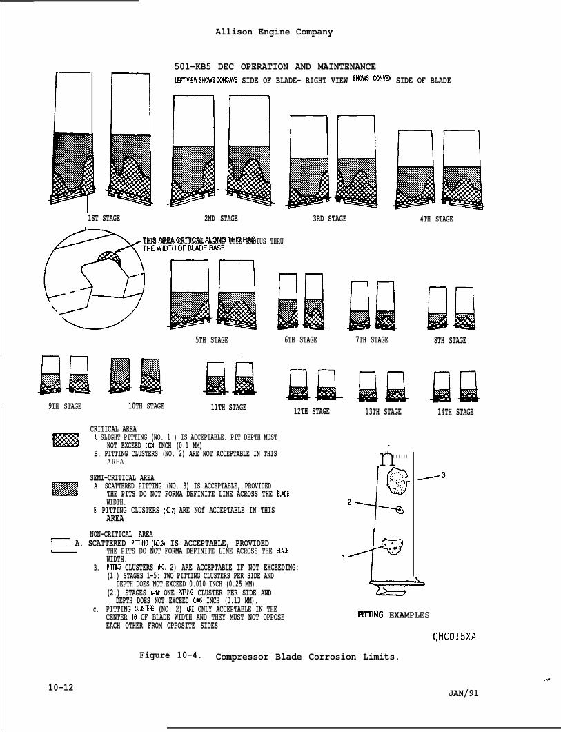
1ST STAGE
Allison Engine Company
501-KB5 DEC OPERATION AND MAINTENANCELE17VIEWSHOWSCQNCAVE SIDE OF BLADE– RIGHT VIEW SHOWS CONVEX SIDE OF BLADE
rlrlnll
2ND STAGE 3RD STAGE
/5%T”Ew’DP77-lTHIS AREA CRITICAL ALONG THIS RADIUS THRU
il BQ5TH STAGE
Iiiiiiiiiiiiil I)IIIB4 Jiiiiiia9TH STAGE 10TH STAGE 11TH STAGE
6TH STAGE 7TH STAGE
CRITICAL AREA
Ifz%llA. SLIGHT PITTING (NO. 1 ) IS ACCEPTABLE. PIT DEPTH MUST
NOT EXCEED 0.W4 INCH (0.1 MM)
12TH STAGE 13TH STAGE
4TH STAGE
B. PITTING CLUSTERS (NO. 2) ARE NOT ACCEPTABLE IN THISAREA
SEMI-CRITICAL AREAA. SCATTERED PITTING (NO. 3) IS ACCEPTABLE, PROVIDED
THE PITS DO NOT FORMA DEFINITE LINE ACROSS THE bLADEWIDTH.
B. PITTING CLUSTERS (NO.2) ARE NOf ACCEPTABLE IN THISAREA
I I
B.
c.
10-12
NON-CRITICAL AREAm A. SCATTERED PIITING [NO.3) IS ACCEPTABLE, PROVIDED
THE PITS DO NOT FORMA DEFINITE LINE ACROSS THE BIADEWIDTH.PrTTING CLUSTERS (NO. 2) ARE ACCEPTABLE IF NOT EXCEEDING:(1.) STAGES 1-5: TWO PITTING CLUSTERS PER SIDE AND
DEPTH DOES NOT EXCEED 0.010 INCH (0.25 MM).(2.) STAGES 6-14: ONE PITTING CLUSTER PER SIDE AND
DEPTH DOES NOT EXCEED 0.CQ5 INCH (0.13 MM).PITTING CLUSTERS (NO. 2) ARE ONLY ACCEPTABLE IN THECENTER 1/3 OF BLADE WIDTH AND THEY MUST NOT OPPOSEEACH OTHER FROM OPPOSITE SIDES
n. ..- . . . . . . .1(3,;.. . . . ,. . . . . . ..
s ‘,..;. .,., :,.,.:.
.- .:’..,.. .
+
. ., ● ✌
1
8TH STAGE
Jiuil14TH STAGE
PllllNG EXAMPLES
-&
QHC015XA
Figure 10-4. Compressor Blade Corrosion Limits.
.@
JAN/91
Allison Engine Company
501-KB5 DEC OPERATION AND MAINTENANCE
4. Special process motoring washes, for cleaning the compressor ifchemical and water is unavailable or not effective and abrasivecleaning is not desired (Ref. Paragraph 10-22).
5. Online compressor washing using approved cleaners (Ref. IndustrialService Letter - 3, Revision No. 3).
E. The best method and frequency of application depend upon the condi-tions under which the engine operates. As a general rule, the com-pressor should be at least water washed each day after operating inthe salt laden environment. The cleaning methods and frequencyshould be determined by frequent compressor inspections, operatingconditions, and performance evaluations. Some conditions may requiremore than one cleaning method to maintain compressor cleanliness.
10-19. WATER RINSE.
A. Water rinse is done by spraying fresh, pottable, filtered water intothe compressor air inlet while the engine is being motored by thestarter. The purpose is to remove water soluble contaminates fromthe gas path of the engine. It is also used to rinse out residuesafter chemical wash of the engine.
1. Frequency of Water Rinse.
a. An engine which has ingested salt water or mist directly intothe compressor air inlet shall receive a motoring water rinsewash after each day’s use.
b. An engine in a salt laden environment which has not beenoperated for a period of three days shall receive a water rinsewash prior to operation.
c. An engine which has received a water wash immediately prior tobecoming inactive may remain inactive for a period of fourteen(14) days. If inactivity is to continue, the water wash appli-cation must be reapplied at the end of the 14th day unless aninspection indicates that the need does not exist.
d. Engines which have visually observable compressor blade andvane contamination and/or which show a trend of deterioratingperformance should receive a water rinse wash and/or liquidcleaner chemical wash.
2. Materials for Water Rinse.
JAN/91
a. Water: Use pottable water if possible. Fresh, drinkable, filter-ed water is the lowest acceptable quality. The flow rate is 3.5gallons (13.25 liters) per minute for a total of 10 gallons (38liters). Flow can be continuous or divided into equal motoringtime intervals, as required, depending on starter limitations.
10-13
I
Allison Engine Company
501-KB5 DEC OPERATION AND MAINTENANCE
b. Wetting agent: A wetting agent is recommended and if used, thewetting agent should be a nonionic detergent that does notcontain sulphur or phosphorous. Approved wetting agents are:
NOTE
The wetting agent mixture is one ounce (30 mL) of 100% agent per 100liquid ounces (2 958 mL) of water to get a 1% solution. Mix two ounces(60 mL) of the l% solution per gallon (3.79 L) to the water rinse.
● Tergitol 15-S-9 (Union Carbide Corporation)● Aerosol Type OT (American Cyanamid Chemical Corporation)
c. Antifreeze: If the ambient temperature is 32*F (O*C) or less, mixmethanol (methylalcohol, Ch30H) or isopropanol (isopropylalcohol) at a minimum mixture ratio of one part to three partswater.
B. Equipment for Water Rinse.
1. The equipment used should be adaptable for both water rinse andchemical wash. The equipment must be capable of supplying rinsewater or the water and chemical mixture under pressure to a finespray nozzle at the compressor air inlet at a volume of 3.5 gpm(13.25 Lpm). The spray nozzle may be mounted or hand held andshould provide a fine spray that covers the engine inletuniformly. Some installations may have water rinse and wash spraysystems incorporated.
NOTE
Chemical wash agent manufacturers are a good source for wash systems orwash system designs (Ref. Paragraph 10-20, Step C-2).
C. Precautions.
1.
2.
3.
Make sure oil supply to engine is ON, while the fuel and ignitionis OFF while the engine in motoring.
Obey any starter restrictions recommended by the startermanufacturer or damage may occur to the starter.
If ambient temperature is 32°F (O”C) or less Drevent freezinq r)er. .preceding Step’A, 2-c.
.? .
D. Procedures for Water Rinse.
1. Service the wash equipment with water rinse prepared with wettingagent and antifreeze if necessary.
10-14 JAN/91
Allison Engine Company
10-20.
A.
B.
c.
Do
501-KB5 DEC OPERATION AND
2. Motor (crank) the engine with the(oil supply ON, fuel and ignition
NOTE
Bleed valves should be held closed
MAINTENANCE
starter in the motoring modesystems OFF).
during wash and rinse.
3. Begin injecting the water rinse when the engine (Nl) rpm reachesmotoring speed, N1 rpm should be no more than 1800 rpm.
4. Stop water rinse after 10 gallons (38 liters) of rinse has beeninjected, then stop motoring. If necessary, the rinse can be donein more than one motoring cycle, but be sure to stop water flowbefore stopping motoring.
5. Within 30 minutes the engine should be started and operated for atleast 5 minutes to dry the engine. Idle speed is satisfactory.
CHEMICAL WASH.
Chemical Wash the compressor internally with a chemical washand water mixture is the ~referred method of cleaning. Chem
agentcal Wash
is done by spraying a chemical and water mixture into the engineinlet while the engine is being motored by the starter. The purposeis to clean the gas path of the compressor to maintain optimumperformance and reduce corrosive damage. Chemical Wash is effective,convenient, and does not damage the engine.
Frequency of Chemical Wash. Engines which have visually observablecompressor blade and vane. contamination or which show a trend ofdeteriorating performance should be chemical washed
Materials for Chemical Wash.
1. Water used in the chemical wash mixture must meet the samerequirements as discussed for Materials for Water Rinse, Paragraph10-19, Step A-2.
2. Listed below are chemical wash agents that have been tested andapproved for compatibility with the materials within the engine.The cleaninq effectiveness of cleaners may differ with the type ofcontamination present. Comply with the chemical cleanermanufacturer’s instructions for mixture concentrations.
NOTE
not exceed the chemical manufacturer’s recommendations “for thechemical concentration.
JAN/91 10-15
Allison Engine Company
501-KB5 DEC OPERATION AND MAINTENANCE
Product Manufacturer
Ardrox 624 Uresco ArdroxB & B 3100 Brulin ChemicalCee Bee R674 McGean RohcoG. T. E. RochemPenair M5704 Penetone Corp.Penetone 19 Penetone Corp.*RMC Ivar RivenaesS E 310 Rochestor MidlandT C 200 AeromarineTurboclean Kent Chemical Ltd.Turco 5884 Purex Div. of Turco
*ZOK 27 Airworthy Ltd.512M Racascan
*May also be used as an online compressor cleaner.
D. Equipment for Chemical Wash.
NOTE
Refer to Equipment for Water Rinse, Paragraph 10-19, Step B.
E. Precautions.
1.
2.
3.
Do not inject chemical wash mixture into the compressor air inletif the CTIT is above 150°F (66”C). The flash (kindling) point ofsome cleaning chemicals is quite low. Make sure the enginetemperature is below this point before chemical wash is initiated.
A water rinse and a drying cycle are required after a chemicalwash per Paragraph 10-19, Step D.
If the ambient temperature is below the freezing point of thechemical solution,” refer to the chemical manufacturer’srecommendations to prevent freezing.
CAUTION
USE OF UNAPPROVED ENGINE CHEMICAL CLEANERS MAY DAMAGE ENGINE AND/OR IT’SCOMPONENTS.
4. Do not use unapproved engine chemical cleaners. The approvedchemical cleaners have been tested for compatibility with thematerials in the engine.
5. Make sure the oil supply to the engine isignition systems are OFF while the engine
6. Obey any starter restrictions recommendeddamage may occur to the starter (Refer to
10-16
ON and the fuel andis motoring.
by the manufacturer orOEM’s Manual).
JAN/91
Allison Engine Company
501-KB5 DEC OPERATION AND ~INILNANCt
7. If an in-line siphon type mixer is used, be sure it uses thecorrect ratio of chemical wash mixture. This type of mixer issensitive to viscosity and supply pressure.
8. Gelling or excessive foaming of a chemical cleaner in the engineusually indicates the engine was too hot.
F. Chemical Wash Procedure.
1. Service the chemical wash equipment with the cleaning chemical andwater, prepared with wetting agent and antifreeze if necessary.
2. Motor (crank) the engine with the starter in the motoring mode(oil supply ON, fuel and ignition systems OFF).
3. Close bleed valves.
4. Begin injecting the chemical wash mixture when the engine (Nl)rpm reaches maximum motoring speed, N1 rpm must be 1800 rpm orbelow.
5. Stop the flow of chemical wash mixture when the recommended amountof cleaner has been injected, then stop motoring. If necessary,the wash can be done in more than one motoring cycle, but be sureto stop the flow of chemical wash mixture before stoppingmotoring.
6. Allow the cleaner mixture to work as recommended by themanufacturer, usually 10 to 15 minutes.
7. Water rinse and run the engine per Paragraph 10-19, Step D., untilwater comes out clean.
8. If visual inspection reveals the compressor is still contaminated,repeat the chemical wash or try one of the special cleaningprocedures (Ref. Paragraph 10-22.) If compressor is stillcontaminated, clean with abrasive cleaning (Ref. Paragraph 10-21).
10-21. ABRASIVE (GROUND SHELL) CLEANING.
A. Abrasive cleaning (ground shell cleaning) is done while the engine isrunning. Abrasive cleaning works by allowing the engine to ingestspecially prepared ground walnut shells which scour the compressorgas path and are then burned in the combustion section. It isespecially effective for removing dry baked-on deposits. The processis mildly erosive to metal parts, and very erosive to the marinized(corrosion resistant) coating in the compressor. The use of abrasivecleaning should not be needed and can be avoided by maintaining aclean compressor by cleaning frequently by the water rinse method,chemical wash method or using special cleaning processes.
JAN/91 10-17
Allison Engine Company
501 -KB5 DEC OPERATION AND MAINTENANCE
CAUTION
ALTHOUGH ABRASIVE (GROUND SHELL) CLEANING IS THE MOST EFFECTIVE CLEANINGMETHOD, IT SHOULD BE MINIMIZED DUE TO THE EROSIVE EFFECT ON COMPRESSORBLADES AND AIR AND OIL SEALS. TRY ALL OTHER CLEANING METHODS, SUCH AS,WATER RINSE, CHEMICAL WASH, AND/OR SPECIAL CLEANING PROCESSES BEFOREUSING GROUND SHELL CLEANING. USE OF GROUND SHELL CLEANING IS RECOMMEND-ED ONLY WHEN ALL OTHER METHODS WILL NOT RECOVER ENGINE PERFORMANCE SUF-FICIENTLY AFTER SHAFT HORSEPOWER LOSS HAD REACHED 5 PERCENT OR MORE.
B. Frequency of Ground Shell Cleaning. Ground shell cleaning isdamaging to the marinized coating in the compressor and should beavoided. Contamination that resists all other cleaning methodsshould be removed by ground shell cleaning if engine performancereduction is severe. Frequent water rinse and chemical wash cleaningis even more important to engines which have been cleaned abrasively.
C. Materials for Ground Shell Cleaning.
CAUTION
TO AVOID CHANCE OF PUTTING CONTAMINATED WALNUT SHELLS INTO AN ENGINEWHICH WILL CAUSE SERIOUS DAMAGE, IT IS RECOMMENDED THAT USERS ORDER THEWALNUT SHELLS UNDER P/N 23002488. IT IS ALSO RECOMMENDED THAT ANYPARTIALLY USED PACKAGE NOT BE SAVEDAS AN OPENED PACKAGE IS CONSIDEREDTO BE CONTAMINATED.
1. One gallon (3.8 liters) packages of ground walnut shells which hasbeen properly sized, graded and cleaned may be ordered fromAllison parts outlets by part number 23002488. To assure theground walnut shell is the correct size, type, and is notcontaminated, it is recommended that users order ground walnutshells under these part numbers. Any partially used packageshould be discarded as the integrity of an opened package cannotbe relied upon.
CAUTION
ONLY GROUND APRICOT PITS CONFORMING TO MILITARY SPEC MIL-G-5634C, TYPE111, MAY BE USED AS APPROVED SUBSTITUTE FOR THE WALNUT SHELLS. GROUNDAPRICOT PITS ARE AVAILABLE FROM AGRASHELL INCORPORATED, 4560 EAST 26THSTREET, LOS ANGELES, CALIFORNIA 90040. TURBO SOFT BLAST, MEDIUM GRADE,HAS ALSO BEEN APPROVED AND IS AVAILABLE FROM TURCO PRODUCTS, 24600 SOUTHMAIN STREET, CARSON, CALIFORNIA 90745.
2. Ground apricot pits conforming to Military Spec MIL-G-5634C, typeIII, may be used.
10-18 JAN/91
Allison Engine Company
501-KB5 DEC OPERATION AND MAINTENANCE
CAUTION
SCREEN ALL BULK GROUND SHELL MATERIAL THROUGH A NO. 12 MESH SCREEN -APPROXIMATELY 0.066 INCH (1.68 MM) - AND ONTOA NO. 20 MESH SCREEN -APPROXIMATELY 0.033 INCH (0.84 mm). USE ONLY THE MATERIAL THAT PASSESTHE NO. 12 AND NOT THE NO.20 SCREENS. MAKE A CLOSE VISUAL INSPECTION OFTHE MATERIAL CONTAINED BETWEEN THE SCREENS AND REMOVE ANY HARD, FOREIGN,MAllER CAPABLE OF CAUSING ENGINE DAMAGE. FINALLY, CHECK THE SHELLS WITHAMAGNETTO REMOVE POSSIBLE METAL SLIVERS. COPPER, ALUMINUM OR PLASTICSCREENS ARE PREFERRED. PLACE IN A SEALED CONTAINER TO PREVENTCONTAMINATION.
D. Equipment for Ground Shell Cleaning.
1. A suitable dispenser capable of injecting two gallons (7.6 liters)of ground shells into the engine air inlet in five minutes isrequired.
NOTE
A ground shell dispenser, 6799610, may be obtained from Allison.
2. The equipment must be capable of a flow rate adjustment to thedesired rate. Adjust the ground shell flow rate for a unitdesigned like the one represented in Figure 10-5 as follows:
a. A flow rate of two gallons (7.6 liters) of ground shells infive minutes is desired. The rate should not exceed one halfgallon per minute.
b. The outlet of the ground shell dispenser in the inlet plenumshould be located in a position expected to allow good distribu-tion through the compressor inlet. The compressor inlet air-flow causes a lower pressure in the plenum which causes air tobe drawn through the ground shell dispenser (Ref. Figure 10-6).
c. The first time the ground shell dispenser is used, set theadjustable orifice at the base of the hopper conservativelysmall . Follow the cleaning procedure and while cleaning,adjust the orifice to achieve the desired flow rate. TheON-OFF valve should be completely open.
d. The flow rate should not require adjustment on subsequentcleaning.
E. Precautions for Ground Shell Cleaning.
1. Be sure ground shell meets the specifications as discussed inmaterial for ground shell cleaning, preceding Step C.
JAN/91 10-19

10-22.
10-20
Allison Engine Company
501-KB5“DEC OPERATION AND MAINTENANCE
2. Ground shell cleaning must be done only while the engine is run-ning with the acceleration bleed valves closed, above 13,000 N1rpm.
3. Make sure that ground shell dispenser is internally clean and dry,i.e., free of anything that could disturb shell flow.
F. Procedure for Ground Shell Cleaning.
1. Check the ground shell cleaning equipment for cleanliness.Install and service it with one to two gallons (3.8 to 7.6 liters)of approved clean ground shells.
2. If the engine uses air bleed from the engine diffuser ports,install blanking plates to prevent contamination of the enginesystem by the ground shells.
3. When ready to begin cleaning, increase the engine (Nl) speed tobetween 13,800 and 14,600 rpm.
4. Begin the flow of ground shell.
CAUTION
GROUND SHELL FLOW RATE MUST NOT EXCEED 1/2 GALLON (1.9 LITERS) PERMINUTE. EXCESSIVE USE OF GROUND SHELL CLEANING IS NOT RECOMMENDED. USEONLY THE AMOUNT NECESSARY TO RESTORE PERFORMANCE, BUT DO NOT EXCEED TWOGALLONS (7.6 LITERS). DAMAGE TO ENGINE MAY OCCUR.
5. Monitor the engine (Nl) rpm at all times and DO NOT use more thantwo gallons (7.6 liters) of ground shells.
6. Shut down the engine, remove the cleaning equipment and restorethe engine to normal operating configuration.
SPECIAL CLEANING PROCESSES.
NOTE
Special cleaning processes have been used successfully for unusualcontamination problems or in place of the more standard cleaningprocesses. Special cleaning processes include:
Kerosene and water, with or without chemical cleanersSteam and steam with chemical cleaner and water
JAN/91
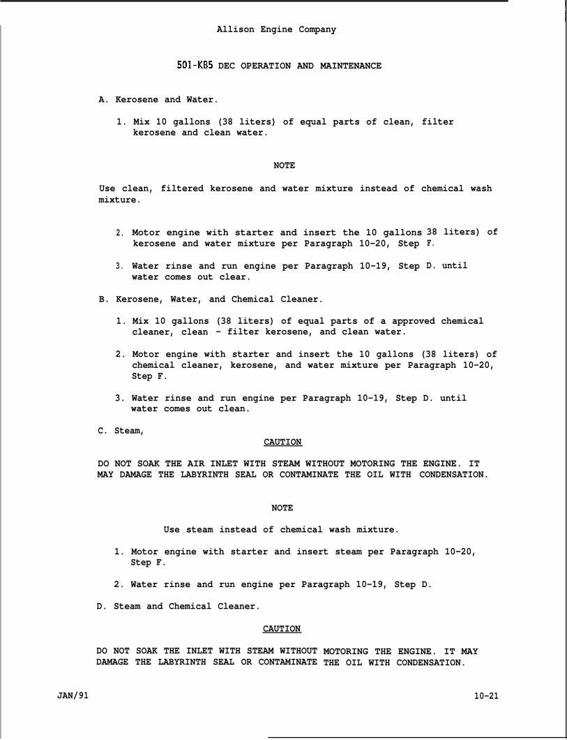
IAllison Engine Company
501-KB5 DEC OPERATION AND MAINTENANCE
A. Kerosene and Water.
1. Mix 10 gallons (38 liters) of equal parts of clean, filterkerosene and clean water.
NOTE
Use clean, filtered kerosene and water mixture instead of chemical washmixture.
2.
3.
Motor engine with starter and insert the 10 gallonskerosene and water mixture per Paragraph 10-20, Step
Water rinse and run engine per Paragraph 10-19, Step
38 liters) ofF.
D. untilwater comes out clear.
B. Kerosene, Water, and Chemical Cleaner.
1. Mix 10 gallons (38 liters) of equal parts of a approved chemicalcleaner, clean - filter kerosene, and clean water.
2. Motor engine with starter and insert the 10 gallons (38 liters) ofchemical cleaner, kerosene, and water mixture per Paragraph 10-20,Step F.
3. Water rinse and run engine per Paragraph 10-19, Step D. untilwater comes out clean.
C. Steam,CAUTION
DO NOT SOAK THE AIR INLET WITH STEAM WITHOUT MOTORING THE ENGINE. ITMAY DAMAGE THE LABYRINTH SEAL OR CONTAMINATE THE OIL WITH CONDENSATION.
NOTE
Use steam instead of chemical wash mixture.
1. Motor engine with starter and insert steam per Paragraph 10-20,Step F.
2. Water rinse and run engine per Paragraph 10-19, Step D.
D. Steam and Chemical Cleaner.
CAUTION
DO NOT SOAK THE INLET WITH STEAM WITHOUTDAMAGE THE LABYRINTH SEAL OR CONTAMINATE
JAN/91
MOTORING THE ENGINE. IT MAYTHE OIL WITH CONDENSATION.
10-21
Allison Engine Company
501 -KB5 DEC OPERATION AND MAINTENANCE
NOTE
Some of the chemical cleaners list incompatible for use with steam. Checkfor compatibility and recommendations.
Paragraph 10-20, Step C-2. arethe chemical cleaner manufacturer
1. A fixture for combinina steam and a chemical cleaner is shown in.Figure 10-7.
10-22
2. Motor engine with starter and insert the steam and chemical cleanerper Paragraph 10-20, Step F.
3. Water rinse and run engine per Paragraph 10-19, Step D.
JAN/91
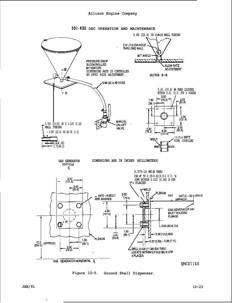
Allison Engine Company
501-KB5 DEC OPERATION AND MAINTENANCE0.88 (22.4) OD XO.06(1.5) WALL TUBING
DISPENSING RATE IS CONTROLLED ADJUSTMENTBY ORIFCE PLUG ADJUSTMENT. SECTliN B-B
1- B0.41 (10.4) DIA THRU LOCATEDWITHIN 0,01 (0.3) OTP 4 PLACES
\
0.750 (19.05) OD X 0.125 (3.18)WALL TUBING
~ 0.88 (22.4) OD XO.06 (1.5).
1.0 (25.4) NPT
k-1.13(22,6) PIPE COUPLING
1.75(44.5)
GAS GENERATOR DIMENSIONS ARE IN INCHES (MILLIMETERS)VERTICLE
$0.375-16 UNC-2B THRUCSK 9)0 TO 0.39-0.42(9.9-1 0.7) DIA
— (It!!)fi LOCATE WITHIN 0.015 (0.38) R OTPT4 PLACES
TT+ -.0W5-16BOLT ?,~.\~w~/pLENuM16.0( 45T.2)-~0(5566)
+6“’wwg‘ .l (APPROX)
I--i-+ -r--tl-l-ro’” -’o
1(! I---
A_ .—G-N GENERATOR-~iZWTAL ~
Figure 10-5. Ground Shell Dispenser.
QHCO1lXA
JAN/91 10-23
,

Allison Engine Company
/’-2
SE
AND MAINTENANLt
/
SAFETY SCREEN
/INLET BELL
Ik /
L\/ 4= ‘ -- A-M
Hp /
ENG’INE
~ LOCATEDONBAFFLE.ALLGROUND SHELL CLEANING PORT
QHC016XD
Figure 10-6. Typical Plenum (Plan View).
10-24 JAN/91
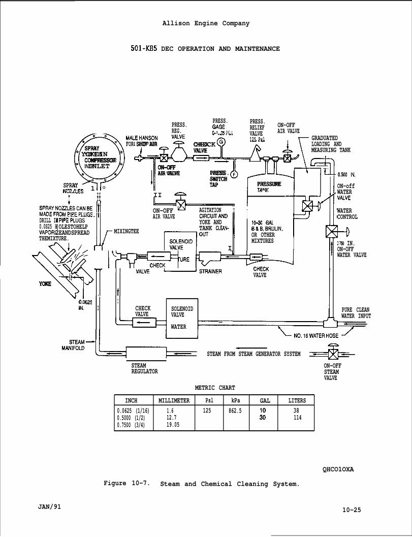
Allison Engine Company
501-KB5 DEC OPERATION AND MAINTENANCE
PRESS. PRESS.nAr2c PRESS.UAUL RELIEF ON-OFF
REG. 11-~ as DC I VALVE AIR VALVE
Q‘“-*~
125 PslI
GRADUATED0 0
SPRAY FOR SHOP AIR CHECK G LOADING AND0 YOKEIN 0 !_ VALVE MEASURING TANK
COMPRESSOR0 INLET 0
ON-OFF0 0
1
AIR VALVE PRESS. ~ %
1 °SWITCH
SPRAY TAP PRESSURE.(-- . . TAAM INULLLC3 II II + I,ru .,.
1t Ill ~1 lKzl-.fYPIPE PLUGS. I
k
AIR VALVE CIRCIJTANDVHPEPLUGS{OLESTOHELP YOKE AND
1
10-30 GAL
ZEANDSPREAD MIXINGTEE TANK CLEAN-
ra”” I
B&B,BRULIN,THEMIXTURE. OR OTHER
al./.MIXTURES I 7
I II II A I --h-l+ ‘~%#OhOES_C_~BE Ill ON-OFF u AGITATION II IDRILL IN ‘“--
0.0S25 HVAPORL r]
‘%% hi :.-4\ ~
\T>
., G.,- -,, ..,,.-,,
7VALVE
YOKEt
f).k25I
IIN, CHECK SOLENOID
VALVE VALVE
WATER —\
JAN/91
M“d4-&
0.5CQ IN.ON-offWATERVAIVE
WATERCONTROL
HD.750 IN.ON-OFFWATER VALVE
PURE CLEANWATER INPUT
-
-STEAM FROM STEAM GENERATOR SYSTEM 45=
STEAM ON-OFFREGULATOR STEAM
VALVEMETRIC CHART
*INCH MILLIMETER Psl kPa GAL LITERS
0.0625 (1/16) 1.6 125 862.5 380.5000 (1/2) 12.7 : 1140.7500 (3/4) 19.05
QHCO1OXA
Figure 10-7. Steam and Chemical Cleaning System.
10-25
Paracra~h
11-1
11-2
11-3
11-4
11-5
11-6
11-7
11-8
11-9
11-10
11-11
11-12
11-13
11-14
11-15
11-16
11-17
11-18
AllisonEngin eCompany
501-KB5 DEC OPERATION AND MAINTENANCE
SECTION 11
COMPRESSOR AIR BLEED 5YSTEM
TABLE OF CONTENTS
Description
Description and Operation
Troubleshooting
Speed Sensitive Valve
Bleed Valves
Air Filter
Description and Operation
Removal
Cleaning
Installation
Speed Sensitive Valve
Description and Operation
Removal
Installation
Compressor Air Bleed Valves
Description and Operation
Removal
Repair of Valve Assembly
Installation
Paqe No.
11-3
11-3
11-6
11-6
11-7
11-7
11-7
11-7
11-11
11-11
11-11
11-12
11-12
11-14
11-14
11-14
11-15
11-15
Fiaure No.
11-1
11-2
11-3
11-4
11-5
Allison Engine Company
501 -KB5 DEC OPERATION AND MAINTENANCE
INDEX TO FIGURES
Title Paqe No.
Compressor Air Bleed System Schematic 11-4
Troubleshooting Chart 11-5
Compressor Air Bleed Systems Components 11-9
Compressor Bleed and Speed Sensitive Valves 11-13
Screen and Shield Installation 11-17
11-2 JAN/91
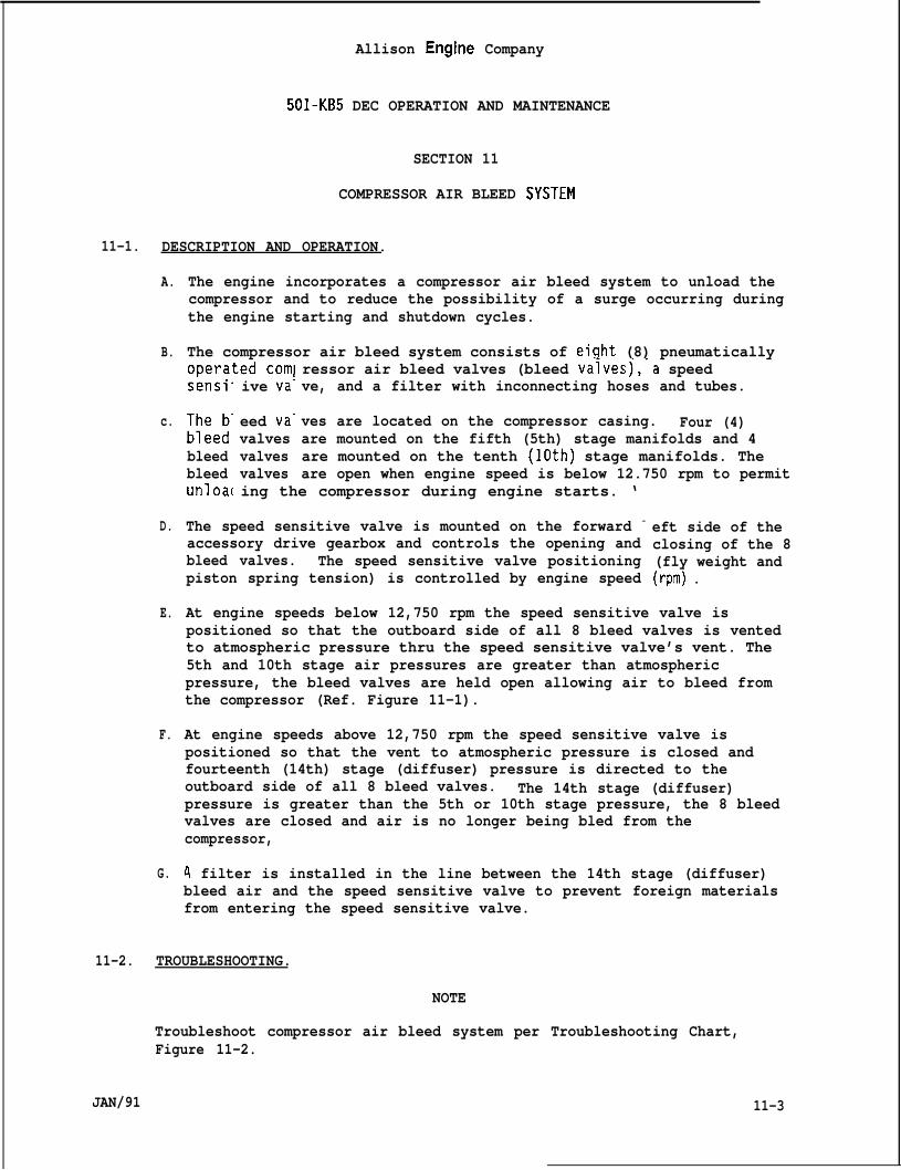
Allison Engine Company
501-KB5 DEC OPERATION AND MAINTENANCE
SECTION 11
COMPRESSOR AIR BLEED $YSTEM
11-1. DESCRIPTION AND OPERATION.
A.
B.
c.
D.
E.
F.
G.
The engine incorporates a compressor air bleed system to unload thecompressor and to reduce the possibility of a surge occurring duringthe engine starting and shutdown cycles.
The compressor air bleed system consists of eight (8) pneumaticallyoDerated comlsensi”
;;:e:”
bleedbleedunloa[
ive va!
eed va-valvesvalvesvalves
ressor air bleed valves (bleed vaivesj,-a speedve, and a filter with inconnecting hoses and tubes.
ves are located on the compressor casing. Four (4)are mounted on the fifth (5th) stage manifolds and 4are mounted on the tenth (lOth) stage manifolds. Theare open when engine speed is below 12.750 rpm to permit
ing the compressor during engine starts. ‘
The speed sensitive valve is mounted on the forward -
accessory drive gearbox and controls the opening andbleed valves. The speed sensitive valve positioningpiston spring tension) is controlled by engine speed
eft side of theclosing of the 8(fly weight and(rpm) .
At engine speeds below 12,750 rpm the speed sensitive valve ispositioned so that the outboard side of all 8 bleed valves is ventedto atmospheric pressure thru the speed sensitive valve’s vent. The5th and 10th stage air pressures are greater than atmosphericpressure, the bleed valves are held open allowing air to bleed fromthe compressor (Ref. Figure 11-1).
At engine speeds above 12,750 rpm the speed sensitive valve ispositioned so that the vent to atmospheric pressure is closed andfourteenth (14th) stage (diffuser) pressure is directed to theoutboard side of all 8 bleed valves. The 14th stage (diffuser)pressure is greater than the 5th or 10th stage pressure, the 8 bleedvalves are closed and air is no longer being bled from thecompressor,
A filter is installed in the line between the 14th stage (diffuser)bleed air and the speed sensitive valve to prevent foreign materialsfrom entering the speed sensitive valve.
11-2. TROUBLESHOOTING.
NOTE
Troubleshoot compressor air bleed system per Troubleshooting Chart,Figure 11-2.
JAN/91 11-3
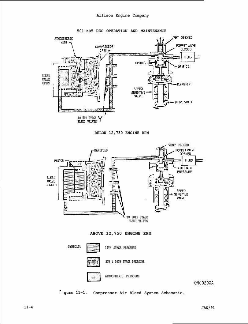
501-KB5
ATMOSPHERICVENT
1
BLEEDVALVEOPEN
Allison Engine Company
DEC OPERATION AND MAINTENANCEA. .VENT OPENED
TO 5TH STAGEBLEED VALVESY
BELOW 12,750 ENGINE RPM
~ VENT CLOSED
U. .~...:.:.. . . .
SYMBOLS:
L1
r MANIFOLD
. . . .. . . .:.:.,,...
. . . . . . . .
. . . . . . . . . . . . . . . . . . . . . . . . . . . . . . . . . . . . . . . . . . . . . . . . . . . . . . . . . .
F
11-4
gure 11-1
w TO 10TH STAGEBLEED VALVES
ABOVE 12,750 ENGINE RPM
m
. . . . . . . . . . .. . . . . . . . . . .. . . . . . . . . . . . . . . . . . . . . . . .. . . . . . . . . . . .. . . . . . . . . . . 14TH STAGE PRESSURE. . . . . . . . . . .. . . . . . . . . . . . . . . . . . . . . ~..
o
. : . . .. .. .. . .. .. . . ... .. . . . . . .. ... ... .. . . . . . . . . . 5TH & 10TH STAGE PRESSURE“.$ ::::::.”.:. . . . . . . . . . . . . .
c1 ATMOSPHERIC PRESSURE
QHC029XA
. Compressor Air Bleed System Schematic.
JAN/91
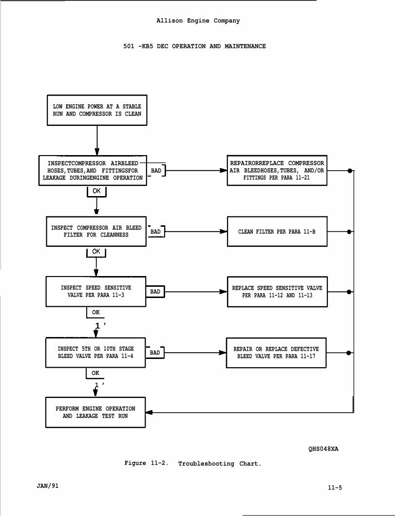
Allison Engine Company
501 -KB5 DEC OPERATION AND MAINTENANCE
LOW ENGINE POWER AT A STABLERUN AND COMPRESSOR IS CLEAN
w
INSPECTCOMPRESSOR AIRBLEED REPAIRORREPLACE COMPRESSORHOSES,TUBES,AND FITTINGSFOR BAD > AIR BLEEDHOSES,TUBES, AND/OR ●
LEAKAGE DURINGENGINE OPERATION FITTINGS PER PARA 11-21
INSPECT COMPRESSOR AIR BLEEDFILTER FOR CLEANNESS
*
BAD D CLEAN FILTER PER PARA 11-B ●
INSPECT SPEED SENSITIVE BAD * REPLACE SPEED SENSITIVE VALVEVALVE PER PARA 11-3 PER PARA 11-12 AND 11-13 ●
OK
1 ’
INSPECT 5TH OR 10TH STAGE BAD > REPAIR OR REPLACE DEFECTIVEBLEED VALVE PER PARA 11-4 BLEED VALVE PER PARA 11-17 ●
OK
1 ’
PERFORM ENGINE OPERATIONAND LEAKAGE TEST RUN *
JAN/91
QHS048XA
Figure 11-2. Troubleshooting Chart.
11-5
Allison Engine Company
501 -KB5 DEC OPERATION AND MAINTENANCE
11-3. SPEED SENSITIVE VALVE.
A.
B.
c.
D.
E.
Remove outlet hose (1, Figure 11-3) and install a 100 psi (690 kPa)air pressure gage in the speed sensitive valve (3) outlet port.
Remove inlet hose (2) and apply 50 psig (345 kPag) air pressure tothe inlet port of the speed sensitive valve. Replace speed sensitivevalve (3) if any indication of pressure is observed on the airpressure gage installed on the outlet port.
Apply a thin film of Ablube, MIL-L-25681, to the speed sensitivevalve inlet port threads. Install inlet hose (1) to speed sensitivevalve (3) and torque hose’s coupling nut to 200-250 lb in. (22.6-28.2N-m).
Operating the engine above 12,750 rpm, inspect for pressure at theoutlet port. If no pressure is present at the outlet port, replacethe speed sensitive valve (3).
If reauired, remove air qaqe, appl.v a thin coat of Ablube,MIL-L-’2568l~ to the outl~t-port” th~ead, and install outlet hose (1)to speed sensitive valve (3). Torque hoses’s coupling nut to 325-400lb in, (36.8-45.1 Nom).
11-4. BLEED VALVES.
A. Remove air hoses (4 and 5, Figure 11-3) from tee (6) on the upperright side of the compressor.
NOTE
Hose (4, Figure 11-3) controls the top (12 o’clock) and left (9o’clock) side 4 bleed valves. Hose (5) controls the right (3 o’clock)and bottom (6 o’clock) side 4 bleed valves.
B.
co
D.
11-6
Inspect bleed valve operation by applying mouth pressure (pressure toclose and vacuum to open) on hoses (4 and/or 5). Each bleed valve inthe set of 4 should open and close freely (observe movement throughscreens surrounding bleed valves).
Repair or replace any sluggish or inoperative bleed valve perParagraph 11-17.
If required, apply a thin film of Ablube, MIL-L-25681, to the threadsand install hoses (4 and 5) to tee (6). Torque hose’s coupling nutsto 200-250 lb in. (22.6-28.2 Nom).
JAN/91
Allison Engine Company
501 -KB5 DEC OPERATION AND MAINTENANCE
11-5. AIR FILTER.
11-6. DESCRIPTION AND OPERATION.+
A. The air filter is installed in the compressor air bleed systembetween the compressor diffuser (14th stage) and the speed sensitivevalve.
NOTE
The filter rating in a nominal of 10 micron and absolute of 25 micron.
B. The filter prevents foreign material from entering the speedsensitive valve, which may cause a malfunction of the speed sensitivevalve.
11-7. REMOVAL.
A. Remove inlet hose (2, Figure 11-3) and inlet tube (10) from filter(13).
B. Remove bolt (11) retaining filter clamp (12) to CIT sensor and removefilter (13) and clamp (13).
C. If required, remove clamp (12) from filter.
11-8. CLEANING.
Note
If required, disassemble filter for cleaning.
A. Remove housing (14, Figure 11-3) and seal (15) from filter element(16). Discard seal.
DO NOT USE A CLOTH TO DRYTHE SPEED SENSITIVE VALVE
CAUTION
FILTER ELEMENT. LINT NAY BE INTRODUCED INTOANDA MALFUNCTION MAY OCCUR.
Note
If an ultrasonic cleaner is not available, clean filter element andhousing Per Step C.
JAN/91 11-7
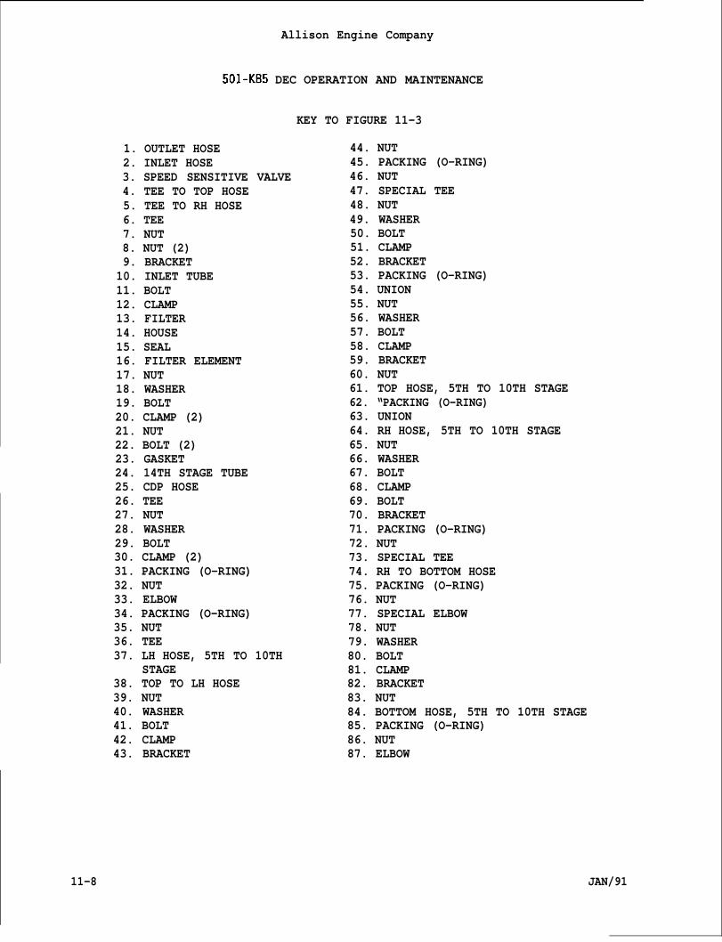
Allison Engine Company
501-KB5 DEC OPERATION AND MAINTENANCE
KEY TO FIGURE 11-3
1. OUTLET HOSE 44. NUT2. INLET HOSE 45. PACKING (O-RING)3. SPEED SENSITIVE VALVE 46. NUT4. TEE TO TOP HOSE5. TEE TO RH HOSE6. TEE7. NUT8. NUT (2)9. BRACKET10. INLET TUBE11. BOLT12. CLAMP13. FILTER14. HOUSE15. SEAL16. FILTER ELEMENT17. NUT18. WASHER19. BOLT20. CLAMP (2)21. NUT22. BOLT (2)23. GASKET24. 14TH STAGE TUBE25. CDP HOSE26. TEE27. NUT28. WASHER29. BOLT30. CLAMP (2)31. PACKING (O-RING)32. NUT33. ELBOW34. PACKING (O-RING)35. NUT36. TEE37. LH HOSE, 5TH TO 10TH
STAGE38. TOP TO LH HOSE39. NUT40. WASHER41. BOLT42. CLAMP43. BRACKET
47. SPECIAL TEE48. NUT49. WASHER50. BOLT51. CLAMP52. BRACKET53. PACKING (O-RING)54. UNION55. NUT56. WASHER57. BOLT58. CLAMP59. BRACKET60. NUT61. TOP HOSE, 5TH TO 10TH STAGE62. “PACKING (O-RING)63. UNION64. RH HOSE, 5TH TO 10TH STAGE65. NUT66. WASHER67. BOLT68. CLAMP69. BOLT70. BRACKET71. PACKING (O-RING)72. NUT73. SPECIAL TEE74. RH TO BOTTOM HOSE75. PACKING (O-RING)76. NUT77. SPECIAL ELBOW78. NUT79. WASHER80. BOLT81. CLAMP82. BRACKET83. NUT84. BOTTOM HOSE, 5TH TO 10TH STAGE85. PACKING (O-RING)86. NUT87. ELBOW
11-8 JAN/91
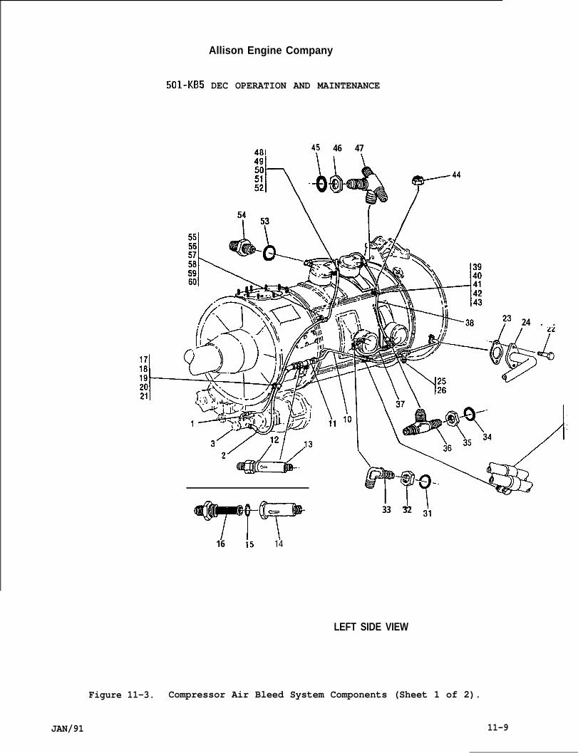
Allison Engine Company
501-KB5 DEC OPERATION AND MAINTENANCE
481 4: 46 47t
TrT16 15 14
24 . .
&+yp!iiii33 32 31
LEFT SIDE VIEW
Figure 11-3. Compressor Air Bleed System Components (Sheet 1 of 2).
JAN/91 11-9
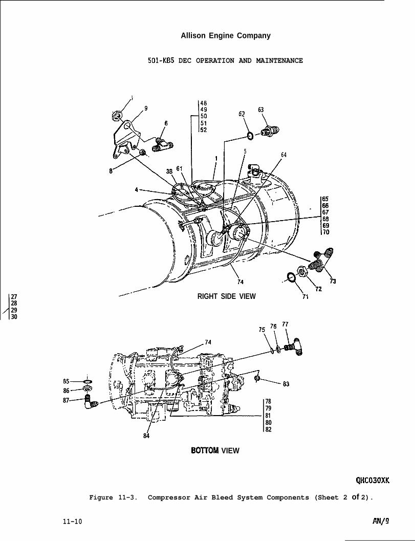
/
27282930
Allison Engine Company
501-KB5 DEC OPERATION AND MAINTENANCE
7
/’ 148
1
/
6263
J-b
5I 64
/-- RIGHT SIDE VIEW ’71
:1
85A86 -----@+87
84
7879818082
BOITOM VIEW
QHC030XK
Figure 11-3. Compressor Air Bleed System Components (Sheet 2 of 2).
11-10
Allison Engine Company
501-KB5 DEC OPERATION AND MAINTENANCE
B. Clean filter element (16) and housing (14) using an ultrasoniccleaner per cleaning equipment manufacturer instructions and allow toair dry. .
C. Optional Cleaning Procedure as follows:
1. Soak housing (14) and filter element (16) in mineral spirits,AMS3160, for at least 15 minutes.
2. Clean housing (14) and filter element (16) using a soft bristlebrush and rinse in mineral spirits, AMS3160.
3. Use filter air (reverse direction to normal flow) to dry, do notuse a cloth. If not completely dry allow to air dry.
D. Apply a thin film of Ablube, MIL-L-25681, to internal threads offilter element (16) and install seal (15) and housing (14). Torqueto 300-360 lb in. (33.9-40.6 Nom) and lockwire housing and filterelement.
11-9. INSTALLATION.
A.
B.
c.
D.
11-10.
11-11.
A.
B.
JAN/91
Apply a thin film of Ablube, MIL-L-25681, to filter (13, Figure 11-3)hose and tube threads.
If required, install clamp (12) on filter (13).
install filter (13) and clamp (12) to CIT sensor and secure with bolt(11). Torque bolt to 70-85 lb in. (8.0-9.6 N“m) and lockwire bolt.
Install inlet hose (2) and inlet tube (10) to filter (13). Torqueboth coupling nuts to 200-250 lb in. (22.6-28.2 Nom).
SPEED SENSITIVE VALVE.
DESCRIPTION AND OPERATION.
The speed sensitive valve is mounted on the forward left side of theaccessory drive gearbox. The speed sensitive valve controls theopening and/or closing of the 8 bleed valves.
At engine speed below 12,750 rpm the piston spring pressure overcomesflyweight force venting the area between the 8 bleed valve and thespeed sensitive valve, allowing the 5th and 10th stage pressure toforce open the bleed valve pistons and bleeds the 5th and 10th stagepressure to the atmospheric (Ref. Figure 11-1).
11-11

Allison Engine Company
501-KB5 DEC OPERATION AND MAINTENANCE
C. At engine speed above 12,750 rpm the flyweight force overcomes pistonspring pressure, which opens the poppet valve and closes the vent,allowing the 14th stage (diffuser) pressure to overcome the 5th and10th stage pressure closing the bleed valve pistons. Now, all of thecompressor air is used for engine operation.
11-12. REMOVAL.
A. If, Required, remove air inlet bell (Ref. to OEM Manual).
B. Remove outlet hose (1, Figure 11-3) and inlet hose (2) from speedsensitive valve.
C. Remove nuts (1, Figure 11-4), washers (2), gasket (3), and speedsensitive valve (4) from accessory drive gearbox. Discard gasket.
11-13. INSTALLATION.
A. Make sure mounting pads on accessory drive gearbox and speedsensitive valve (4, Figure 11-4) are clean and free of foreignmaterial.
B. Apply a thin film of Permatex, No. 1372, to both sides of the gasket(3) and install on the accessory drive gearbox mounting pad for thespeed sensitive valve.
CAUTION
IF A NEW SPEED SENSITIVE VALVE IS INSTALLED, MAKE SURE THAT THE VENTSHIPPING CAP IS REMOVED OR DAMAGE MAY OCCUR.
NOTE
It may be required to rotate the speed sensitive valve’s drive shaftslightly to align the splines of the accessory drive gearbox and speedsensitive valve.
c.
D.
E.
11-12
Install speed sensitive valve (4) on accessory drive gearbox andsecure with washers (2) and nuts (1). Torque nuts to 74-89 lb in.(8.4 -10.0 N.m).
Apply thin film of Ablube, MIL-L-25681, to inlet and outlet portthreads of the speed sensitive valve.
Install inlet hose (2, Figure 11-3) to speed sensitive valve inletport. Torque hose’s coupling to 200-250 lb in. (22.6-28,2 N.m).
JAN/91
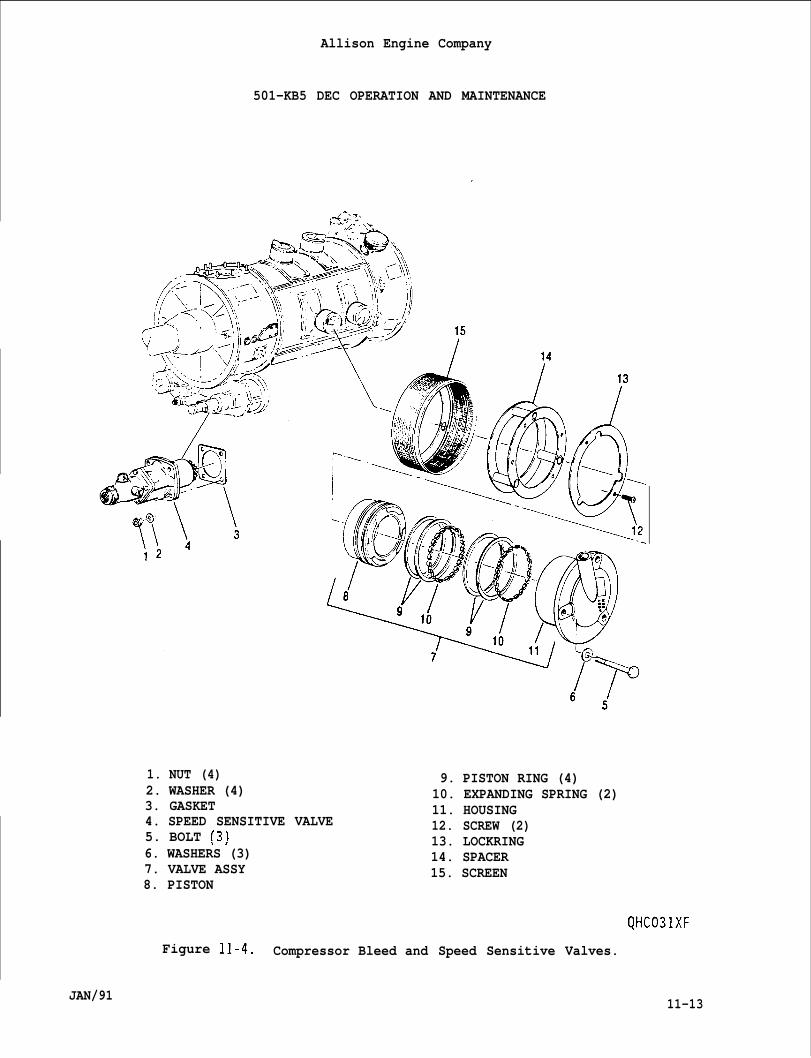
Allison Engine Company
501-KB5 DEC OPERATION AND MAINTENANCE
1. NUT (4)2. WASHER (4)3. GASKET4. SPEED SENSITIVE VALVE5. BOLT (3)\–,6. WASHERS (3)7. VALVE ASSY8. PISTON
9. PISTON RING (4)10. EXPANDING SPRING (2)11. HOUSING12. SCREW (2)13. LOCKRING14. SPACER15. SCREEN
QHC031XF
Figure 11-4. Compressor Bleed and Speed Sensitive Valves.
JAN/91 11-13
F.
11-14.
11-15.
A.
B.
c.
D.
E.
501-KB5
Allison Engine Company
DEC OPERATION AND MAINTENANCE
Install outlet hose (2) to speed sensitive valve outlet port. Torquehose’s coupling nut to 325-400 lb in. (36.8-45.1 Nom).
COMPRESSOR AIR BLEED VALVES.
DESCRIPTION AND OPERATION.
The eight (8) piston type compressor air bleed valves (bleed valves)are mounted on the 8 compressor manifolds, four (4) on the 5th stageand 4 on the 10th stage. The bleed valves are mounted at top (12o’clock), right (3 o’clock), bottom (6 o’clock), and left (9 o’clock)positions of the compressor section.
The opening and closing of the bleed valves are controlled by thespeed sensitive valve (Ref. Paragraph 11-11).
The 8 bleed valves and the speed sensitive valve are connected byhoses in parallel.
The bleed valves are opened to unload the compressor and to reducethe possibility of surge occurring during the engine start and stopcycles. The bleed valves are closed during normal engine operationabove 12,750 engine rpm.
Each bleed valve consists of the following:
1. Three (3) mounting bolts and washers.2. A valve assembly.3. Two (2) screws.4. A lockring.5. A spacer,
NOTE
The top (12 o’clock) 2 bleed valve screens do not have shields wherethe remaining 6 screens do have shields.
6. A screen,
11-16. REMOVAL.
NOTE
Due to different types of hose and fitting (elbow, tee, special tee,etc.) connections, refer to Figure 11-3 and locate the correct type ofhose and fitting connection.
A. Remove the required hose(s) (Ref. Figure 11-3).
11-14 JAN/91
Allison Engine Company
501-KB5 DEC OPERATION AND MAINTENANCE
NOTE
If the screen has a shield, record location for installation.
B. Remove bolts (5, Figure 11-4), washers (6), valve assembly (7),spacer (14) with Iockring (13), and screen (15) from compressor.
C. If required, remove screws (12) and lockring (13) from spacer (14).
D. If required, record and remove fitting (elbow, tee, special tee,etc.), nut, and O-ring from valve assembly (7). Discard O-ring (Ref.Figure 11-3).
11-17. REPAIR OF VALVE ASSEMBLY.
A. Remove assembled piston (8, Figure 11-4) from housing (11).
B. Remove piston rings (9) and expanding spring (10) from piston (8).
C. Inspect all valve assembly components for damage and wear. Replacedamage or worn components.
D. Install expanding springs (10) on piston (8). The cut ends of theexpanding spring must be adjacent to the bottom of each pistongroove.
NOTE
The piston rings are installed in each piston groove with overlaps 160°to 180° apart, also the piston ring overlaps are to be located 70” to100° from cut ends of the expanding springs.
E. Install two piston rings (9) in each piston (8) groove per the abovenote.
F. Lightly coat inside of the housing (11) with Ablube, MIL-L-25681.
G. Compress piston rings (9) with hand pressure ard carefully installassembled piston (8) into housing (11) until the piston is fullyseated (open position) within the housing.
11-18. INSTALLATION.
NOTE
Due to different types of hose and fitting connections, Ref. to Figure11-3 and locate correct type of hose and fitting connections.
JAN/91 11-15
●
●
11-19.
11-20.
11-21.
Allison Engine Company
501 -KB5 DEC OPERATION AND MAINTENANCE
A. If required, install correct O-ring, nut, and fitting into valveassembly (7, Figure 11-4) to record position as outlined in Genera”Maintenance, Section 14. .
B. If required, install lockring (13) on spacer (14) and secure withscrews (12). Torque screw to 12-14 lb in. (1.4-1.7 Nom).
NOTE
The 2 top (12 o’clock) position screens do not have shields, but theremaining 6 screens do have shields and must be installed to positionrecorded on removal. If shield position(s) were not recorded onremoval, refer to Figure 11-5 for correct shield position(s).
For correct valve assembly, Ref. to Figure 11-3.
c.
D.
A.
B.
c.
A.
B.
11-16
Install screen (15, Figure 11-4) to correct position, spacer (14)with Iockrinq (13), and valve assembly (7) to correct ~osition,secure with washers (6) and bolts( 5)-. ‘Torque bolts to 70-85 lb in.(8.0-9.6 Nom). Lockwire bolts.
Install required hose(s) per General Maintenance, Section 14 (Ref.Figure 11-3).
HOSES, TUBES, AND FITTINGS.
DESCRIPTION AND OPERATION.
The two tubes (10 and 24, Figure 11-3) are made of steel and direct14th stage (diffuser) compress air to air filter. A tee separatesthe two tubes and allows for compressor discharge pressure to betaken.
The hoses direct 14th stage (diffuser) compress air from the airfilter thru speed sensitive valve (if opened) to close the bleedvalve (Ref. Figure 11-1).
The fittings, gasket, and O-rings allow connection of the hoses andtubes.
MAINTENANCE.
Leakage may occur from a hose, tube, gasket, O-ring, and/or fitting(elbow, union, tee, etc.) and should be inspected for leakage whilethe engine is in the normal operation mode.
Remove and install hoses, tubes, fittings, O-rings, and gaskets usingFigure 11-3 and General Maintenance procedures, Section 14.
JAN/91
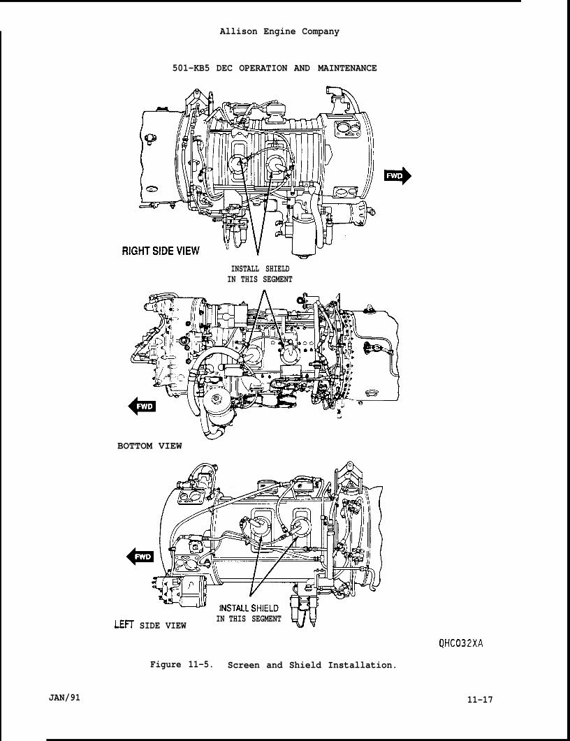
JAN/91
Allison Engine Company
501-KB5 DEC OPERATION AND MAINTENANCE
INSTALL SHIELDIN THIS SEGMENT
wBOTTOM VIEW
LEIT SIDE VIEWIN THIS SEGMENT Wv
QHC032XA
Figure 11-5. Screen and Shield Installation.
11-17
Paraqrauh
12-1
12-2
12-3
12-4
12-5
12-6
12-7
12-8
12-9
12-10
12-11
12-12
12-13
12-14
12-15
12-16
12-17
12-18
12-19
12-20
12-21
12-22
JAN/91
Allison Engine Company
501-KB5 DEC OPERATION AND MAINTENANCE
SECTION 12
COMBUSTION SECTION AND IGNITION SYSTEM
TABLE OF CONTENTS
Description
Combustion Section
Description and Operation
Combustion Outer Case
Description and Operation
Removal
Inspection
Installation
Combustion Liners
Removal
Inspection
Installation
Other Combustion Section Components
Crossover Clamps
Combustion Inner Case
Combustion Inner Case Liner
Engine Ignition System
Description and Operation
Exciter
Description and Operation
Removal
Inspection
Installation
Paqe No.
12-3
12-3
12-5
12-5
12-5
12-8
12-8
12-9
12-9
12-10
12-10
12-12
12-12
12-12
12-12
12-12
12-12
12-13
12-13
12-13
12-14
12-16
12-1
Allison Engine Company
501-KB5 DEC OPERATION AND MAINTENANCE
TABLE OF CONTENTS
ParaqraPh Description
12-23 Igniter, Liner Supports,
(CONT) .
12-24
12-25
12-26
12-27
12-28
12-29
12-30
12-31
Fiqure No.
12-1
12-2
12-3
12-4
12-5
and Liner Body” Supports
Description and Operation
Removal
Inspection
Installation
Lead Assemblies
Removal
Inspection
Installation
INDEX TO FIGURES
Cross Section of Combustion Section
Splitline Locations
Combustion Liner Crossover Clamping
Engine Ignition System
Lockwiring of Igniter, Igniter Lead,and Liner Support
Paqe No.
12-17
12-17
12-17
12-18
12-19
12-20
12-20
12-21
12-21
Paqe No.
12-4
12-7
12-11
12-15
12-21
12-2 JAN/91
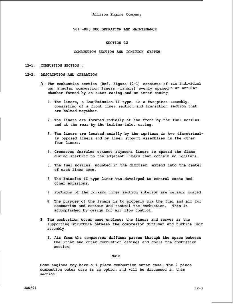
Allison Engine Company
501 -KB5 DEC OPERATION AND MAINTENANCE
SECTION 12
COMBUSTION SECTION AND IGNITION SYSTEM
12-1. COMBUSTION SECTION .
12-2. DESCRIPTION AND OPERATION.
A.
B.
The combustion section (Ref. Figure 12-1) consists ofcan annular combustion liners (liners) evenly spacedchamber formed by an outer casing and an inner casing
1.
2.
3.
4.
5.
6.
7.
8.
The liners, a Low-Emission II type, is a two-piececonsisting of a front liner section and transitionare bolted together.
six individualn an annular
assembly,section that
The liners are located radially at the front by the fuel nozzlesand at the rear by the turbine inlet casing.
The liners are located axially by the igniters in two diametrical-ly opposed liners and by liner support assemblies in the otherfour liners.
Crossover ferrules connect adjacent liners to spread the flameduring starting to the adjacent liners that contain no igniters.
The fuel nozzles, mounted in the diffuser, extend into the centerof each liner dome.
The Emission II type liner was developed to control smoke andother emissions.
Portions of the forward liner section interior are ceramic coated.
The purpose of the liners is to properly mix the fuel and air forcombustion and contain and control the combustion. This isaccomplished by design for air flow control.
The combustion outer case encloses the liners and serves as thesupporting structure between the compressor diffuser and turbine unitassembly.
1. Air from the compressor diffuser passes through the space betweenthe inner and outer combustion casings and cools the combustionsection.
NOTE
JAN/91
Some engines may have a 1 piece combustion outer case. The 2 piececombustion outer case is an option and will be discussed in thissection.
12-3
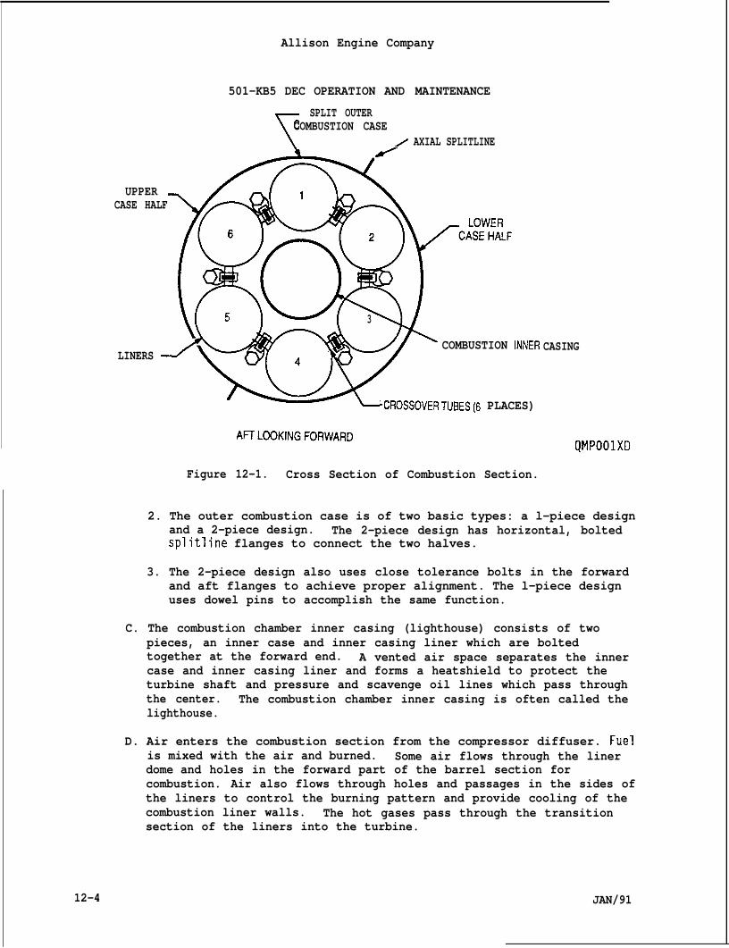
12-4
Allison Engine Company
501-KB5 DEC OPERATION AND MAINTENANCE
r
SPLIT OUTERCOMBUSTION CASE
z AXIAL SPLITLINE
(%0h
UPPERCASE HALF
3
COMBUSTION INNERLINERS ~
‘CROSSOVERTUBES(6 PLACES)
CASING
A17LOOKINGFORWARDQMPOOIXD
Figure 12-1. Cross Section of Combustion Section.
2. The outer combustion case is of two basic types: a l-piece designand a 2-piece design. The 2-piece design has horizontal, boltedsplitline flanges to connect the two halves.
3. The 2-piece design also uses close tolerance bolts in the forwardand aft flanges to achieve proper alignment. The l-piece designuses dowel pins to accomplish the same function.
C. The combustion chamber inner casing (lighthouse) consists of twopieces, an inner case and inner casing liner which are boltedtogether at the forward end. A vented air space separates the innercase and inner casing liner and forms a heatshield to protect theturbine shaft and pressure and scavenge oil lines which pass throughthe center. The combustion chamber inner casing is often called thelighthouse.
D. Air enters the combustion section from the compressor diffuser. Fuelis mixed with the air and burned. Some air flows through the linerdome and holes in the forward part of the barrel section forcombustion. Air also flows through holes and passages in the sides ofthe liners to control the burning pattern and provide cooling of thecombustion liner walls. The hot gases pass through the transitionsection of the liners into the turbine.
JAN/91
Allison Engine Company
501-KB5 DEC OPERATION AND MAINTENANCE
E. Components of the combustion section are:
1. Combustion Outer Case (2-piece or l-piece).2. Combustion Liners (6).3. Combustion Liner Supports.4. Combustion Liner Clamps and Spacers.5. Combustion Chamber Inner Casing (Lighthouse).
12-3. COMBUSTION OUTER CASE.
12-4. Descric)tion and Operation.
A. The combustion outer case is the structural support member thatsupports and aligns the diffuser to the turbine assembly.
B. It is a pressure vessel that forms the outer wall of an annulus inwhich the combustion liners are supported. The six combustion linersupports attach to and protrude into the outer combustion case tosupport the combustion liners axially. Igniters are assembled withthe liner supports in liner positions two and five.
NOTE
Some engines may have a 1 piece combustion outer case. The 2 piececombustion outer case is an option and will be discussed in thissection.
C. The 2-piece outer combustion casing has axial split line boltedflanges, whichthe combustioncombustion cas
allows for direct view inspection or replacement ofliners, when l-piece (half) of the 2-piece outerng is removed.
12-5. Removal.CAUTION
THE ENGINE MUST BE SUPPORTED AT THE DIFFUSER AND THE TURBINE UNITASSEMBLY WHILE ONE OF THE OUTER COMBUSTION CASE HALVES IS LOOSE ORREMOVED.
NOTE
To remove and install the one piece combustion outer case the turbineunit assembly must be removed, refer to Section 13.
A. Either half of the outer combustion case may be removed. The upperleft half (referred to as the upper) will expose combustion liners 1,5, and 6. The lower right half (referred to as the lower) willexpose combustion liners 2, 3, and 4. The position of the axial
JAN/91 12-5
Allison Engine Company
501-KB5 DEC OPERATION AND MAINTENANCE
spl itlines allows access to the crossover clamps associated with theexposed combustion liners.
NOTE
● Remove the liner supports and igniter per Paragraph 12-25.
● Record location of all bolts, components, brackets, thermocoupleharness, etc., for installation.
B. Remove components adjacent and attached to the outer combustion casehalf selected for removal, including the three liner supports (onewith an igniter), brackets, and thermocouple harness(s).
CAUTION
ONLY ONE OUTER COMBUSTION CASE HALF MAY BE REMOVED AT A TIME. THEREMAINING CASE HALF MUST REMAIN IN PLACE TO HOLD ALIGNMENT. IF BOTHHALVES NEED TO BE REMOVED AT SAME TIME, THE TURBINE UNIT ASSEMBLY MUST-- --..,----- ------ --.. . . . . . . .-L$t
●
●
c.
D.
DOTO
E.
F.
12-6
KtMUVHJ, KLl_tK I(J 3LL11UN 1.5.
NOTE
It is permissible to use a soft drift (brass or aluminum) to tap outthe close tolerance bolts.
Record the locations of the close tolerance bolts, brackets andextra length bolts at bracket locations for installation.
Remove the nuts and bolts from both horizontal splitline flanges andfrom the splitlines with the diffuser and with the turbine inlet caseas necessary to release the particular case half (Ref. Figure 12-2).
Loosen the nuts two full turns in the splitlines of the diffuser andthe turbine inlet case on the casing half not being removed.
CAUTION
NOT PRY OR INSERT TOOLS BETWEEN ANYTHE SEALING SURFACES MAY OCCUR.
OF THE SPLITLINE FLANGES. DAMAGE
Use jackscrews in the threaded holes in the lower case half splitlineflanges to separate the case halves. Varying the tension on thesupport at the diffuser may help free the case half. Do not pry oruse tooling between any splitlines (Ref. Figure 12-2).
Remove the case half and place it where it will not be damaged.
JAN/91
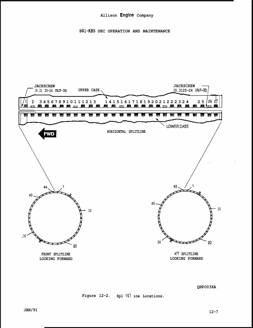
Allison Engine Company
501-KB5 DEC OPERATION AND MAINTENANCE
JACKSCREW JACKSCREW(0.31 25-24 UNJF-3B) UPPER CASE 0.3125-24 UNJF-3B)
\ ●
3 4 5 6 7 8 9 1 0 1 1 1 2 1 3 1 4 1 5 1 6 1 7 1 8 1 9 2 0 2 1 2 2 2 3 2 4 2 5mmm. .mmmm mm m. Un m.m, m.m.mun. mm.
\
HORIZONTAL SPLITLINE
/
40
10
,30
FRONT SPLITLINELOOKING FORWARD
48
4010
30
An SPLITLINELOOKING FORWARD
QHPO03XA
Figure 12-2. Spl itl ine Locations.
JAN/91 12-7
Allison Engine Company
501-KB5 DEC OPERATION AND MAINTENANCE
CAUTION
DO NOT DAMAGE FLANGE SEALING SURFACES.
G. Remove any sealing compound from the sealing face. Use a cloth orScotch Brite dampened with water. If necessary, use a copperwith care not to damage sealing surfaces.
12-6.Inspection (Both 2-~iece or l-piece conficwrations].
A.
B.
Inspect the outer combustion case for cracks, dents, bulges,splitline leakage. Cracks and sharp dents are not allowabledents or bulges to 0.250 in. (6.35 mm) depth or height are a“if the cause is known and corrected.
Discoloration of the outer combustion case is allowable, but
scraper
andSmooth
1 owabl e
shouldbe investigated as a possible indication of fuel nozzle-or combustionliner problems.
12-7. Installation.
A. Prior to placing the removed outer combustion case half in position,coat sealing surfaces of horizontal flanges with EMS-27700 sealant(Plastiseal F).
B.
co
D.
E.
Place the removed outer combustion case half in position. Looselyinstall the combustion liner support assemblies and igniter with newgaskets to ensure axial positioning of the combustion liners.
Use a soft drift to achieve hole alignment and loosely install theclose tolerance bolts (hex head) in the proper holes. Loosely installthe remaining bolts and nuts in the splitlines with the diffuser andwith the turbine inlet case.
In the horizontal splitline flanges, loosely install the closetolerance bolts (hex head) in holes 2, 8, 14, 20 and 26 numbered fromthe diffuser end. Loosely install the remaining bolts and nuts (Ref.Figure 12-2).
Torque the horizontal splitline flange bolts as follows:
1. On one horizontal splitline flange, torque to 140 lb in. (15.8N“m) above prevailing nut torque in the following sequence:
Bolt position numbers 14, 15, 13, 16, 12, 17, 11, 18, 10, 19, 9,20, 8, 21, 7, 22, 6, 23, 5, 24, 4, 25, 3, 26, 2, 27 and 1.
12-8
2. Repeat Step 1. for the opposite horizontal splitline.
JAN/91
30
4.
5.
Allison Engine Company
501-KB5 DEC OPERATION AND MAINTENANCE
On the first splitline, retorque to 265-275 lb in. (29.9-31.1N-m) above prevailing torque in the same sequence as Step 1.
Repeat Step 3. for the opposite splitline.
Remove excess sealant applied in Step A.
F. Torque the close tolerance bolts (hex head) and the remaining boltsand nuts in the splitlines with the diffuser and with the turbineinlet case to 100-110 lb in. (11.3-12.4 N“m) and then torque200-220 lb in. (22.6 to 24.8 N-m).
NOTE
Install combustion liner supports and igniter per Paragraph 12-27.
G. Install the components adjacent and attached to the outer combustioncase half, including the three combustion liner supports (one with anigniter), brackets, and thermocouple harness(s) that were removed forthe procedure.
12-8. COMBUSTION LINERS.
12-9. Removal.
NOTE
The combustion liners can be removed by two methods; (1) With the enginein a shop with the engine’s turbine unit assembly removed and (2) withthe engine installed by removing one of the outer combustion casehalves. The instructions contained here are for method (2) only. Theinstructions for method (1) are contained in Section 13, which ifpossible, is the recommended way.
A.
Ifof
B.
JAN/91
Remove the outer combustion case half (Ref. Paragraph 12-5).
NOTE
more than one combustion liner is to be removed, complete the removaleach one before proceeding to the next combustion liner.
Remove the nut and bolt from the crossover clamp on both sides of thecombustion liner (Ref. Figure 12-3).
12-9
Allison Engine Company
501-KB5 DEC OPERATION AND MAINTENANCE
CAUTION
DO NOT ALLOW CROSSOVER SPACERS OR ANY OTHER MATERIAL TO DROP INTO THEENGINE. ANY MATERIAL DROPPED INTO ENGINE MUST BE REMOVED.
c.
D.
E.
F.
Remove each clamp and the associated spacer(s) from between thecrossover tube ferrules. Note the position and thickness of thespacers. The fuel nozzle attaching bolts may be loosened to allowspacer removal.
Remove the three borescope port plugs associated with the liner fromthe turbine inlet case per Section 13.
Remove the fuel nozzle. Record the position (Ref. Section 4).
Lift the nozzle end of the combustion liner forward and out toremove. Record the position of the combustion liner fortroubleshooting and/or installation.
12-10. Inspection.
NOTE
Refer to Section 3, Engine Inspection and Maintenance Tasks, Paragraph3-6 for inspection and damage limits for combustion liners whether in-stalled or removed. The limits are the most severe conditions that areallowed to continue operation. If combustion liners are either removedor accessible with an outer combustion casing half removed, considera-tion should be given to replacing marginally serviceable liners, orindividual liner sections (front liner section and/or transitionsection).
12-11. Installation.
A. Place the combustion liner in position with the transition sectionopening over the first stage turbine vanes. Work the liner rearwarduntil it is in position. The axial position of the liner isdetermined by the liner support and the liner support ferrule.Measuring the distance may help position the liner for easierinstallation.
B. Install the fuel nozzle with gasket. Tighten bolts finger tight.
C. Use a small drift, punch or screwdriver to align the grommets, andinstall the three associated borescope port plugs with gaskets perSection 13.
12-10 JAN/91
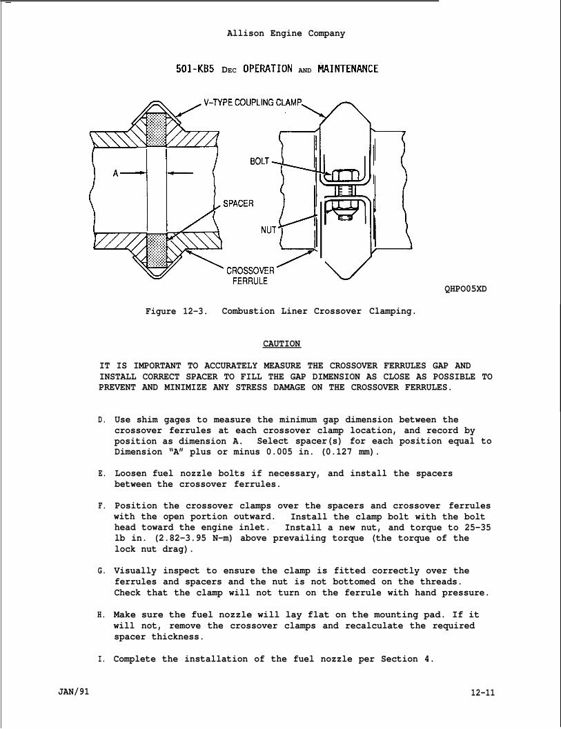
—
Allison Engine Company
501-KB5 DEC OpERATION AND IZUNTENANCE
‘vQHPO05XD
Figure 12-3. Combustion Liner Crossover Clamping.
CAUTION
IT IS IMPORTANT TO ACCURATELY MEASURE THE CROSSOVER FERRULES GAP ANDINSTALL CORRECT SPACER TO FILL THE GAP DIMENSION AS CLOSE AS POSSIBLE TOPREVENT AND MINIMIZE ANY STRESS DAMAGE ON THE CROSSOVER FERRULES.
D.
E.
F.
G.
H.
I.
JAN/91
Use shim gages to measure the minimum gap dimension between thecrossover ferrules at each crossover clamp location, and record byposition as dimension A. Select spacer(s) for each position equal toDimension “A” plus or minus 0.005 in. (0.127 mm).
Loosen fuel nozzle bolts if necessary, and install the spacersbetween the crossover ferrules.
Position the crossover clamps over the spacers and crossover ferruleswith the open portion outward. Install the clamp bolt with the bolthead toward the engine inlet. Install a new nut, and torque to 25-35lb in. (2.82-3.95 N-m) above prevailing torque (the torque of thelock nut drag).
Visually inspect to ensure the clamp is fitted correctly over theferrules and spacers and the nut is not bottomed on the threads.Check that the clamp will not turn on the ferrule with hand pressure.
Make sure the fuel nozzle will lay flat on the mounting pad. If itwill not, remove the crossover clamps and recalculate the requiredspacer thickness.
Complete the installation of the fuel nozzle per Section 4.
12-11
J.
12-12.
12-13.
A.
B.
12-14.
A.
B.
12-15.
A.
B.
12-16.
12-17.
A.
Allison Engine Company
501 -KB5 DEC OPERATION AND MAINTENANCE
When all combustion liners have been installed, inspect andany foreign material. Install the outer combustion case ha-
Paragraph 12-7).
OTHER COMBUSTION SECTION COMPONENTS.
Crossover Clamps.
The six crossover clamps with spacers connect the crossoverof adjacent combustion liners.
removef (Ref.
ferrules
The crossover clamps should be inspected whenever the engine isdisassembled enough to expose them.
Combustion Inner Case.
The combustion inner case is attached to the turbine inlet case andis a slip fit with expander ring seals into the inner bore of thecompressor diffuser. It forms the inner wall of an annulus in whichthe combustion liners are supported.
Inspect the inner combustion casing when other maintenance causes theengine to be dissembled sufficiently for inspection. Inspect forcracks and wear in the piston ring grooves and the mating surfaces ofthe diffuser sleeve. No cracks are allowed. Maximum piston ringgroove width is 0.269 in. (6.83 mm)
Combustion Inner Case Liner.
The combustion inner case liner fits inside the inner combustion caseto form a double wall assembly with an air space between to providethermal protection. The turbine shaft and oil tubes for the frontturbine bearing pass through the bore of the inner combustion caseand liner assembly, which is often called the lighthouse.
Inspect the combustion inner casing liner when other maintenancecauses the engine to be dissembled sufficiently for inspection.Inspect for cracks and damage in the seal grooves. No cracks areallowed.
ENGINE IGNITION SYSTEM.
DESCRIPTION AND OPERATION.
The engine is equipped with a capacitor discharge, high voltage, highenergy type ignition system. The ignition system includes an igni-tion exciter and two spark igniters. The spark igniters are mountedin number 2 and number 5 combustion liners. Two high tension,
12-12 JAN/91
Allison Engine Company
w1-KB5 DEC OPERATION AND MAINTENANCE
shielded lead assemblies connect the ignition exciter to the sparkigniters.
B. The 20 to 29 volts dc input power required by the ignition exciter issupplied through a relay which, in turn, is controlled by the controlsystem. During engine starting, the control circuits energize theignition system at approximately 2200 engine rpm and de-energize thesystem at approximately 8400 engine rpm.
NOTE
The ignition system is the same for gaseous or liquid fuels.
c.
12-18.
12-19.
A.
B.
After ignition takes place in number two and five combustion liners,the flame propagates via crossover tubes to the remaining fourliners. Once the fuel-air mixture is burning, combustion isselfsustaining as long as fuel is supplied.
EXCITER.
Description and O~eration.
The exciter is a high tension, triggered gap, capacitor dischargetype exciter. The exciter furnishes the high voltage required tofire two spark igniters, one in the number 2 and one in the number 5combustion liners. The exciter is a hermetically sealed unit.
The exciter will operate satisfactorily on dc voltaae ranaina between20 and 29 volts. Variations in input ~oltage affec~ the ~pa~k ratebut do not have a proportionate effect on the amount of energydissipated in the spark.
NOTE
For liquid fuel engines the exciter can be mounted on the top of thecompressor section just behind the air intake housing. For gaseous anddual fuel engines the exciter is mounted off the engine in an explosionproof enclosure. The maintenance for either mounted exciter is thesame, the off-engine mounted exciter will be covered in this Section.
12-20.
JAN/91
Removal.
WARNING
THE IGNITION SYSTEM MUST BE OFF FORAT LEAST 5 MINUTES BEFORE HANDLINGTHE EXCITER. THIS PERIOD OF TIME PERMITS BLEED RESISTORS WITHIN THEEXCITER TO DISSIPATE ENERGY STORED IN THE CONDENSERS. SEVERE INJURY ORDEATH MAY OCCUR, IFAN ENERGIZED EXCITER IS HANDLED.
12-13

Allison Engine Company
501-KB5 DEC OPERATION AND MAINTENANCE
NOTE
Hold terminal assembly to prevent lead assembly from turning.
A. Disconnect terminal assemblies (18, Figure 12-4) from exciter (l).
WARN ING
AS AN ADDED PRECAUTION TO GET RID OF ANY DANGEROUS ENERGY WHICH COULDPERSIST IF THE BLEED RESISTORS WERE OPEN, SHORT THE CENTER ELECTRODE OFTHE HIGH TENSION CONNECTOR TO THE CASE OF THE EXCITER.
B. Remove bolts (2), washers (3), nuts (4), and exciter (1) from LH andRH supports (5 and 6).
C. If required, remove nuts (7), LH support (5) and/or RH support (6).
12-21. Inspection.
WARN ING
THE EXCITER TEST MUST NOT BE PERFORMED IN AN AREA WHERE THERE IS THEPOSSIBILITY OF A FUEL LEAK OR ANY OTHER EXPLOSIVE MATERIAL WHICH COULDBE IGNITED. INJURY OR DAMAGE MAY OCCUR.
A. Connect two known good lead assemblies (8, Figure 12-4) and igniters(29) to exciter (l).
WARN ING
NEVER HANDLE ENERGIZED IGNITER. SERIOUSCONTACT WITH AN ENERGIZED IGNITER.
PERSONAL INJURY MAY OCCUR FROM
B. Clip a jumper from the igniter (29) case and to the ground of thepower supply.
CAUTION
CONNECT 24 VOLT POSITIVE LEAD TO THE EXCITER INPUT PIN AND NEGATIVELEAD TO EXCITER CASE. REVERSING POLARITY CAN CAUSE INTERNAL DAMAGE TOTHE EXCITER.
C. Apply 24 volts dc to input terminal of the exciter (l), using aminimum wire size of 16 gage, and observe firing, of the igniter.
12-14 JAN/91
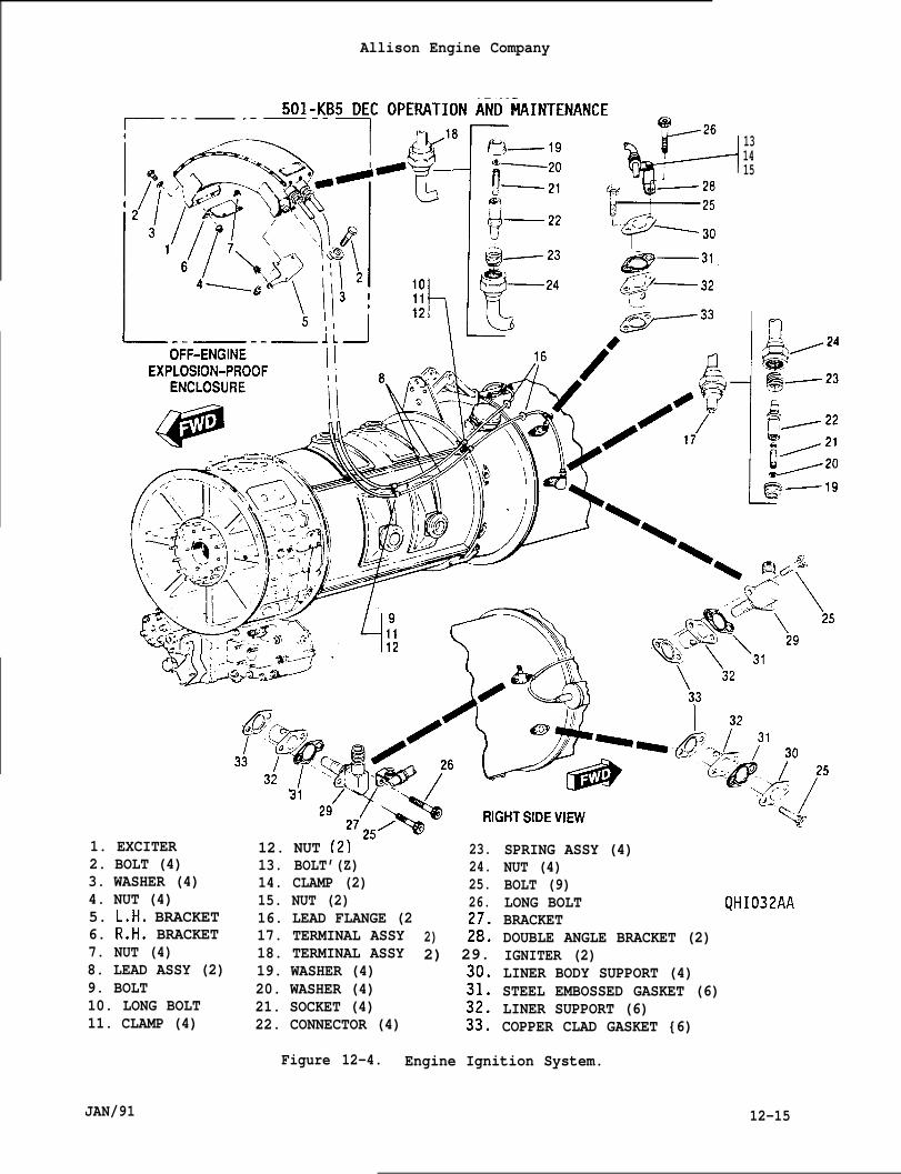
Allison Engine Company
1. EXCITER2. BOLT (4)3. WASHER (4)4. NUT (4)5. L.H. BRACKET6. R.H. BRACKET7. NUT (4)8. LEAD ASSY (2)9. BOLT10. LONG BOLT11. CLAMP (4)
13. BOLT’(Z)14. CLAMP (2)15. NUT (2)16. LEAD FLANGE (217. TERMINAL ASSY18. TERMINAL ASSY19. WASHER (4)20. WASHER (4)21. SOCKET (4)22. CONNECTOR (4)
131415
I f-l
12. NUT (2) 23.24.25.26.
2) :;:2) 29.
:;:
JAN/91
SPRING ASSY (4)NUT (4)BOLT (9)LONG BOLT QHI032AABRACKETDOUBLE ANGLE BRACKET (2)IGNITER (2)LINER BODY SUPPORT (4)STEEL EMBOSSED GASKET (6)LINER SUPPORT (6)COPPER CLAD GASKET {6)
Figure 12-4. Engine Ignition System.
12-15
Allison Engine Company
I 501 -KB5 DEC OPERATION AND MAINTENANCE
CAUTION
NEVER OPERATE AN EXCITER WITHOUT LEADS AND IGNITERS. SPARK INTENSITYIS SUCH THAT CONNECTORS WILL BE DAMAGED FROM ARCING.
I CAUTION
THE IGNITION SYSTEM HAS A MAXIMUM CONTINUOUS RATING OF THREE MINUTES.HOWEVER, TO PREVENT OVERHEATING OF THE EXCITER, THE OPERATING CYCLESHOULD NOT BE MORE SEVERE THAN TWO MINUTES ON, THREE MINUTES OFF, TWOMINUTES ON AND 23 MINUTES OFF. DAMAGE WILL OCCUR, WHEN THE EXCITEROVERHEATS.
D. Determine whether the observed spark is the initial (trigger) spark,or the actual ignition spark. The trigger spark is a continuous,flowing spark, while the ignition spark is instantaneous, verybrilliant, and accompanied by a sharp report. This latter sparkobserved at each igniter is repetitive with a rate of approximatelysix to eight sparks per second. If either igniter fails to fire,fires at a greatly reduced rate, fires intermittently, or fires onlythe trigger spark, replace the exciter.
E. If there is a question about the exciter after the above tests, checkthe unit at 20 volts dc input voltage measured at the input terminalsto the exciter. The minimum acceptable spark rate at 20 volts dcinput voltage is four sparks per second.
12-22. Installation.
A. If removed, install LH support (5, Figure 12-4) and/or RH support(6), secure with nuts (7). Torque nuts to 74-89 lb in. (8.4-10.0Nom).
B. Install exciter (1) to LH and RH supports (5 and 6), secure withbolts (2), washers (3), and nuts (4). Torque nuts to 74-89 lb in.(8.4 -10.0 N-m).
I NOTE
Hold terminal to prevent lead assembly from turning.
C. Install terminal assemblies (18) to exciter (l). Torque terminalnuts (24) to 100-120 lb in. (11.3-13.6 Nom) and lockwire nuts toeach other.
12-16 JAN/91
12-23.
12-24.
A.
B.
co
D.
12-25.
Allison Engine Company
501-KB5 DEC OPERATION AND MAINTENANCE
IGNITER, LINER SUPPORTS, AND LINER BODY SUPPORTS.
Description and Or)eration.
Two igniters are mounted on the outer combustion case, one igniterfor the number two combustion liner and one igniter for the numberfive combustion liner.
The liner supports are used to position the combustion liners andretain them axially.
Combustion liners (number 1, 3, 4, and 6) which do not have ignitershave a liner body support to position and support these combustionliners.
The igniter receives the electrical energy from the exciter duringstarting to ignite the fuel-air mixture in the combustion liners.
Removal.
WARN ING
NEVER HANDLE AN ENERGIZED IGNITER. MAKE SURE THATBEEN OFF FORAT LEAST FIVE MINUTES BEFORE REMOVING
IGNITION SYSTEM HASAN IGNITER. THIS
TIME WILL ALLOW THE EXCITER BLEED RESISTORS TO DISSIPATE ALL ENERGYSTORED IN THE CONDENSERS. SEVERE INJURY OR DEATH MAY OCCUR IF ANENERGIZED IGNITER IS HANDLED.
NOTE
Removal of the igniters and liner body supports are the sameprocedures, except for the lead assemblies. Delete following Step 1.,if only removing the liner body supports.
A.
B.
NOTE
Hold lead assembly to prevent from turning when removing nut.
Disconnect terminal assembly (17, Figure 12-4) from igniter (29).Hold lead assembly (8) to prevent any twisting damage when removingnut (24). Remove lead assembly from igniter by pulling straightoutward with no rotational movement.
Apply penetrating oil, VV-P-216, to bolts (25 and/or 26) and allowsufficient time for penetrating oil to penetrate the threads.
JAN/91 12-17
Allison Engine Company
501-KB5 DEC OPERATION AND MAINTENANCE
NOTE
Record location of long bolts for installation and liner supports.
C. Remove bolts (25 and/or 26), igniter (29) and/or liner body support(30), steel embossed gasket (31), liner support (32), and copper cladgasket (33) from
12-26. Insr)ection.
If liner support issupport may be usedinstallation.
oute~ combustion case. Discard -all ”gaskets”.”
NOTE
worn on one side and not worn through, the lineragain, but will have to be rotated 180 degrees on
A. Inspect liner support (32, Figure 12-4) for wear and/or burning.Wear over 0.03125 (1/32) inch (0.8 mm) deep on both sides or if linersupport is worn through is cause for replacement of the linersupport.
NOTE
During engine operation, the electrodes erode (or burn away) becomingrounded. This is a natural condition and does not affect igniterperformance unless the electrode becomes shorter than the ceramic, whenthis condition occurs, replace the igniter.
B. Inspect the igniter center electrode length. If electrode is shorterthan the ceramic, replace the igniter.
C. Inspect the igniter ceramic tips for cracks. If any cracks arevisible through the carbon coating, replace the igniter.
D. Clean igniter’s carbon deposits using a bristle brush or a clean drycloth.
E. Inspect igniter firing.
WARNING
NEVER HANDLE AN ENERGIZED IGNITER. SERIOUS PERSONAL INJURY MAY OCCURFROM CONTACT WITHAN ENERGIZED IGNITER.
12-18 JAN/91
Allison Engine Company
501-KB5 DEC OPERATION AND MAINTENANCE
WARNING
THE IGNITER TESTPOSSIBILITY OF A
SHOULD NOT BE PERFORMED IN AN AREA WHERE THERE IS THEFUEL LEAK OR ANY OTHER EXPLOSIVE NATERIAL WHICH COULD
BE IGNITED. INJURY OR DAMAGE MAY OCCUR.
1. Connect a known good exciter (1, Figure 12-4) and a lead assembly
12-27.
●
●
(8) to the igniter (29) being “tested. -
2. Clip a jumper from the igniter (29) case and to the ground ofpower supply.
CAUTION
CONNECT 24 VOLT POSITIVE LEAD TO THE EXCITER INPUT PIN AND NEGATIVELEAD TO EXCITER CASE. REVERSING POLARITY CAN CAUSE INTERNAL DAMAGETHE EXCITER.
NOTE
Difference “replacement
F.
G.
A.
n spark rate between theunless the spark rate is
two igniters is not cause forintermittent.
terminal of the exciter, usinq3. Apply 24 volts dc to the inputminimum wire size of 16 gage, and observe the firing. ‘If sp~rkrate is intermittent, replace the igniter.
the
TO
Shut off 24 volts dc power to exciter, short the igniters withinsulated tool.
Remove igniter from test equipments.
Installation.
Apply Ablube, MIL-L-25681, to the bolts’ (25 and/or 26, Fiwre 12-4)threads.
NOTE
The order of assemble must be the following order: copper cladgasket, liner support, steel embossed gasket, and then liner bodysupport or igniter.
Make sure that no moisture, lubricant, or foreign material is in theigniter’s lead terminal insulator or the electrical connector wall ofthe igniter.
. If line support wear is 0.03125 (1/32) inch (0.8 mm) and not wornthrough rotate 180 degree and install.
JAN/91 12-19
Allison Engine Company
501 -KB5 DEC OPERATION AND MAINTENANCE
B. Install copper clad gasket (33), liner support (32), steel embossedgasket (31), and liner body support (30) or igniter (29), secure withAblube threaded bolts (25 and/or 26). Torque bolts to 70-85 lb in.(8.0-9.6 Nom).
CAUTION
HOLD LEAD ASSEMBLY TO PREVENT TURNING WHEN TIGHTENING OR TOROUING NUTTO PREVENT DAMAGE TO THE LEAD ASSEMBLY.
c.
D.
E.
12-28.
12-29.
Connect a terminal assembly (17) to each igniter (29), while holdinglead assembly (8), torque nut (24) to 100-120 lb in. (11.3-13.6Nom).
Lockwire terminal assembly (17) and/or bolts (25 and/or 26) as shownin Figure 12-5.
Repeat Steps A. thru D. until all igniters (29) and liner bodysupport (30) are installed.
LEAD ASSEMBLIES.
Removal.
WARNING
SERIOUS PERSONAL INJURY MAY OCCUR IF IGNITION SYSTEM IS ENERGIZED.
A. Make sure 24 volts dc is removed from exciter (1, Figure 12-4).
UARN ING
THE IGNITION SYSTEM SHOULD BE OFFAT LEAST 5 MINUTES BEFORE HANDLINGTHE IGNITION SYSTEM COMPONENTS. SEVERE INJURY MAY OCCUR.
B. Disconnect terminal assemblies (18, Figure 12-4) from exciter (1)while holding lead assembly (8) to prevent twisting. Remove terminalfrom exciter by pulling straight outward with no rotational movement.
C. Disconnect terminal assemblies (17) from igniters (29) while holdinglead assembly (8) to prevent twisting. Remove terminal from igniterby pulling straight outward with no rotational movement.
NOTE
Record location of clamps and long bolts for installation.
12-20 JAN/91
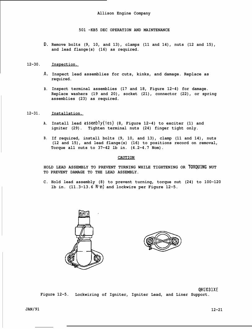
D.
12-30.
A.
B.
12-31.
A.
B.
Allison Engine Company
501 -KB5 DEC OPERATION AND MAINTENANCE
Remove bolts (9, 10, and 13), clamps (11 and 14), nuts (12 and 15),and lead flange(s) (16) as required.
Inspection.
Inspect lead assemblies for cuts, kinks, and damage. Replace asrequired.
Inspect terminal assemblies (17 and 18, Figure 12-4) for damage.Replace washers (19 and 20), socket (21), connector (22), or springassemblies (23) as required.
Installation.
Install lead assembly(ies) (8, Figure 12-4) to exciter (1) andigniter (29). Tighten terminal nuts (24) finger tight only.
If required, install bolts (9, 10, and 13), clamp (11 and 14), nuts(12 and 15), and lead flange(s) (16) to positions record on removal,Torque all nuts to 37-42 lb in. (4.2-4.7 Nom).
CAUTION
HOLD LEAD ASSEMBLY TO PREVENT TURNING WHILE TIGHTENING OR TORQUING NUTTO PREVENT DAMAGE TO THE LEAD ASSEMBLY.
C. Hold lead assembly (8) to prevent turning, torque nut (24) to 100-120lb in. (11.3-13.6 N-m) and lockwire per Figure 12-5.
QHI031XEFigure 12-5. Lockwiring of Igniter, Igniter Lead, and Liner Support.
JAN/91 12-21
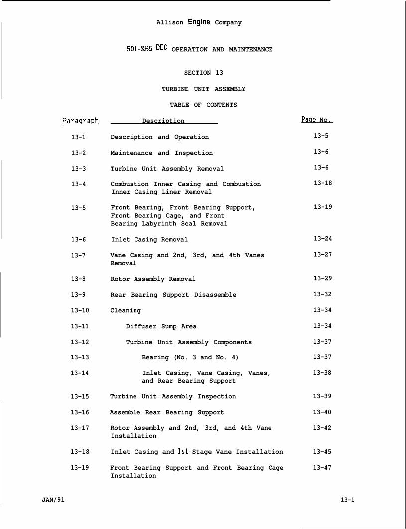
Paraara~h
13-1
13-2
13-3
13-4
13-5
13-6
13-7
13-8
13-9
13-10
13-11
13-12
13-13
13-14
13-15
13-16
13-17
13-18
13-19
JAN/91
Allison Engine Company
501-KB5 DEC OPERATION AND MAINTENANCE
SECTION 13
TURBINE UNIT ASSEMBLY
TABLE OF CONTENTS
Description
Description and Operation
Maintenance and Inspection
Turbine Unit Assembly Removal
Combustion Inner Casing and CombustionInner Casing Liner Removal
Front Bearing, Front Bearing Support,Front Bearing Cage, and FrontBearing Labyrinth Seal Removal
Inlet Casing Removal
Vane Casing and 2nd, 3rd, and 4th VanesRemoval
Rotor Assembly Removal
Rear Bearing Support Disassemble
Cleaning
Diffuser Sump Area
Turbine Unit Assembly Components
Bearing (No. 3 and No. 4)
Inlet Casing, Vane Casing, Vanes,and Rear Bearing Support
Turbine Unit Assembly Inspection
Assemble Rear Bearing Support
Rotor Assembly and 2nd, 3rd, and 4th VaneInstallation
Inlet Casing and 1st Stage Vane Installation
Front Bearing Support and Front Bearing CageInstallation
Paae No.
13-5
13-6
13-6
13-18
13-19
13-24
13-27
13-29
13-32
13-34
13-34
13-37
13-37
13-38
13-39
13-40
13-42
13-45
13-47
13-1
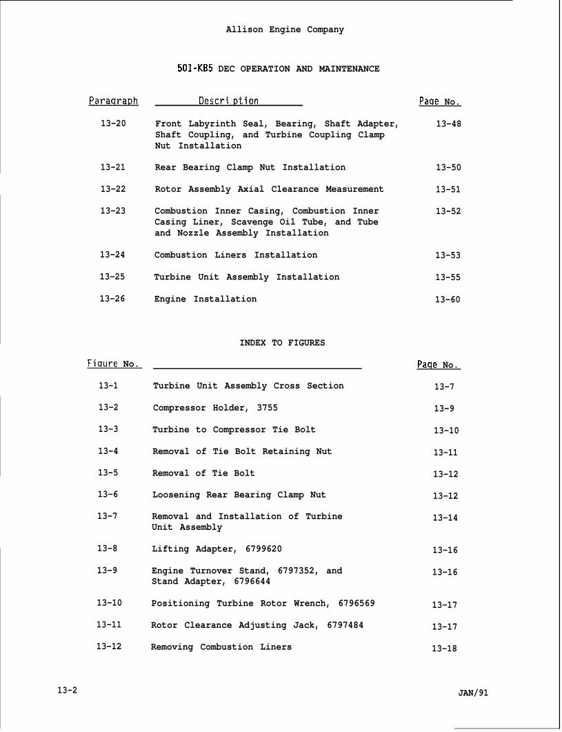
Allison Engine Company
501-KB5 DEC OPERATION AND MAINTENANCE
ParaqraDh
13-20
13-21
13-22
13-23
13-24
13-25
13-26
Fiqure No.
13-1
13-2
13-3
13-4
13-5
13-6
13-7
13-8
13-9
13-10
13-11
13-12
13-2
t)escri Dtion
Front Labyrinth Seal, Bearing, Shaft Adapter,Shaft Coupling, and Turbine Coupling ClampNut Installation
Rear Bearing Clamp Nut Installation
Rotor Assembly Axial Clearance Measurement
Combustion Inner Casing, Combustion InnerCasing Liner, Scavenge Oil Tube, and Tubeand Nozzle Assembly Installation
Combustion Liners Installation
Turbine Unit Assembly Installation
Engine Installation
INDEX TO FIGURES
Turbine Unit Assembly Cross Section
Compressor Holder, 3755
Turbine to Compressor Tie Bolt
Removal of Tie Bolt Retaining Nut
Removal of Tie Bolt
Loosening Rear Bearing Clamp Nut
Removal and Installation of TurbineUnit Assembly
Lifting Adapter, 6799620
Engine Turnover Stand, 6797352, andStand Adapter, 6796644
Positioning Turbine Rotor Wrench, 6796569
Rotor Clearance Adjusting Jack, 6797484
Removing Combustion Liners
Paqe No.
13-48
13-50
13-51
13-52
13-53
13-55
13-60
Paqe No.
13-7
13-9
13-10
13-11
13-12
13-12
13-14
13-16
13-16
13-17
13-17
13-18
JAN/91
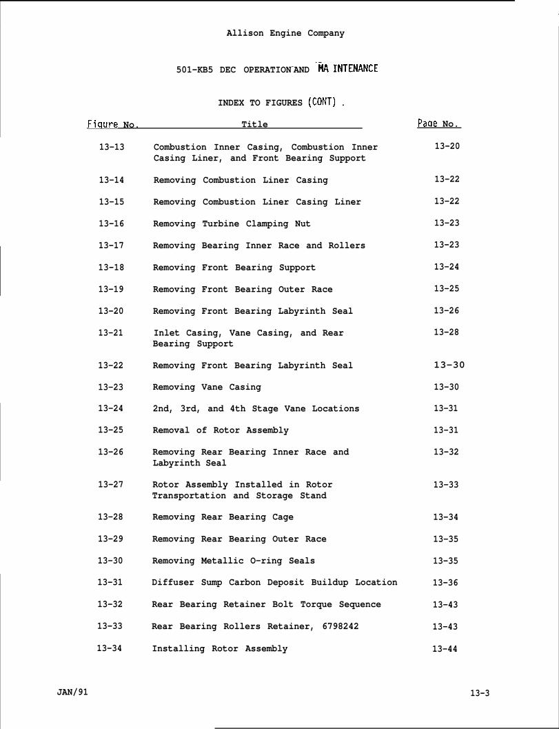
1Allison Engine Company
501-KB5 DEC OPERATION-AND -~ INTENANCE
INDEX TO FIGURES (CONT) .
Fiqure No. Title
13-13
13-14
13-15
13-16
13-17
13-18
13-19
13-20
13-21
13-22
13-23
13-24
13-25
13-26
13-27
13-28
13-29
13-30
13-31
13-32
13-33
13-34
JAN/91
Combustion Inner Casing, Combustion InnerCasing Liner, and Front Bearing Support
Removing Combustion Liner Casing
Removing Combustion Liner Casing Liner
Removing Turbine Clamping Nut
Removing Bearing Inner Race and Rollers
Removing Front Bearing Support
Removing Front Bearing Outer Race
Removing Front Bearing Labyrinth Seal
Inlet Casing, Vane Casing, and RearBearing Support
Removing Front Bearing Labyrinth Seal
Removing Vane Casing
2nd, 3rd, and 4th Stage Vane Locations
Removal of Rotor Assembly
Removing Rear Bearing Inner Race andLabyrinth Seal
Rotor Assembly Installed in RotorTransportation and Storage Stand
Removing Rear Bearing Cage
Removing Rear Bearing Outer Race
Removing Metallic O-ring Seals
Diffuser Sump Carbon Deposit Buildup Location
Rear Bearing Retainer Bolt Torque Sequence
Rear Bearing Rollers Retainer, 6798242
Installing Rotor Assembly
Paqe No.
13-20
13-22
13-22
13-23
13-23
13-24
13-25
13-26
13-28
13-30
13-30
13-31
13-31
13-32
13-33
13-34
13-35
13-35
13-36
13-43
13-43
13-44
13-3
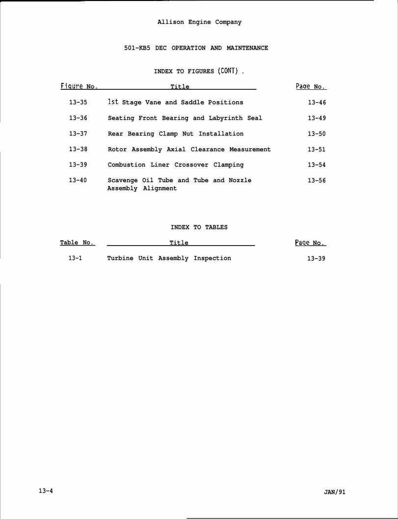
Allison Engine Company
501-KB5 DEC OPERATION AND MAINTENANCE
INDEX TO FIGURES (CONT) .
Fiqure No. Title
13-35 1st Stage Vane and Saddle Positions
13-36 Seating Front Bearing and Labyrinth Seal
13-37 Rear Bearing Clamp Nut Installation
13-38 Rotor Assembly Axial Clearance Measurement
13-39 Combustion Liner Crossover Clamping
13-40 Scavenge Oil Tube and Tube and NozzleAssembly Alignment
INDEX TO TABLES
Table No. Title
13-1 Turbine Unit Assembly Inspection
Pacie No.
13-46
13-49
13-50
13-51
13-54
13-56
Paqe No.
13-39
13-4 JAN/91
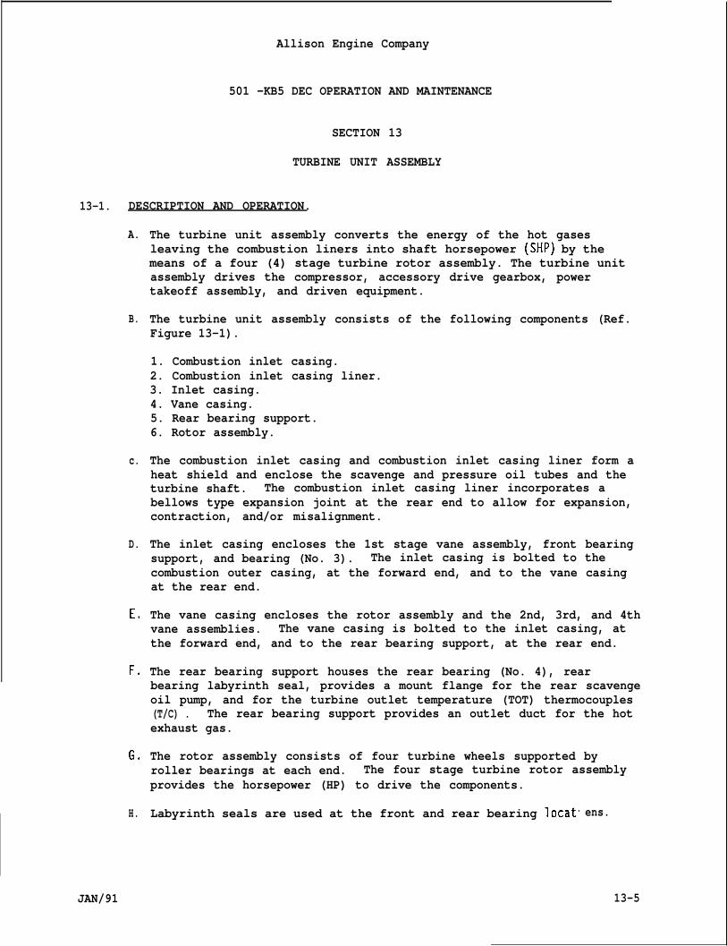
Allison Engine Company
501 -KB5 DEC OPERATION AND MAINTENANCE
SECTION 13
TURBINE UNIT ASSEMBLY
13-1. DESCRIPTION AND OPERATION.
A.
B.
c.
D.
E.
F.
Go
H.
The turbine unit assembly converts the energy of the hot gasesleaving the combustion liners into shaft horsepower (SHP) by themeans of a four (4) stage turbine rotor assembly. The turbine unitassembly drives the compressor, accessory drive gearbox, powertakeoff assembly, and driven equipment.
The turbine unit assembly consists of the following components (Ref.Figure 13-1).
1. Combustion inlet casing.2. Combustion inlet casing liner.3. Inlet casing.4. Vane casing.5. Rear bearing support.6. Rotor assembly.
The combustion inlet casing and combustion inlet casing liner form aheat shield and enclose the scavenge and pressure oil tubes and theturbine shaft. The combustion inlet casing liner incorporates abellows type expansion joint at the rear end to allow for expansion,contraction, and/or misalignment.
The inlet casing encloses the 1st stage vane assembly, front bearingsupport, and bearing (No. 3). The inlet casing is bolted to thecombustion outer casing, at the forward end, and to the vane casingat the rear end.
The vane casing encloses the rotor assembly and the 2nd, 3rd, and 4thvane assemblies. The vane casing is bolted to the inlet casing, atthe forward end, and to the rear bearing support, at the rear end.
The rear bearing support houses the rear bearing (No. 4), rearbearing labyrinth seal, provides a mount flange for the rear scavengeoil pump, and for the turbine outlet temperature (TOT) thermocouples(T/C) . The rear bearing support provides an outlet duct for the hotexhaust gas.
The rotor assembly consists of four turbine wheels supported byroller bearings at each end. The four stage turbine rotor assemblyprovides the horsepower (HP) to drive the components.
Labyrinth seals are used at the front and rear bearing locat ens.
13-5JAN/91
Allison Engine Company
501 -KB5 DEC OPERATION AND MAINTENANCE
13-2. MAINTENANCE AND INSPECTION .
A. Allison Gas Turbine recommends the turbine unit assembly be sent to aMajor Repair Center after 30,000 operation hours for inspection,repair, and overhaul.
B. Inspect for surface defects of the turbine rotor blades and turbinevane assemblies as outlined in Section 3, Engine Inspections andMaintenance Tasks.
C. Surface defects of the turbine rotor blades and vane assemblies areclassified as dents, nicks, cracks, erosion, and hot corrosion(sulfidation).
13-3. TURBINE UNIT ASSEMBLY REMOVAL.
NOTE
Removal of the turbine unit assembly can be done at the MaintenanceService Level 1 (Operational Level) provided fully trained qualifiedpersonnel and the special tools and equipment are available.
A.
B.
c.
D.
Reasons for local removal of the turbine unit assembly are:
1. To perform a hot section inspection (HSI).
2. To replace the turbine unit assembly and/or the rotor assembly.
3. To replace a damaged component of the turbine unit assembly.
Have available suitable lifts, stands, working areas, and all specialtools required to perform the task.
Remove engine as outlined in Section 1, Engine Description.
The following removal procedures are assumed that the engine isremoved and mounted in a transportation and storage stand, 6799609.
WARNING
THE IGNITION SYSTEM SHOULD BE OFF AT LEAST 5 MINUTES BEFORE HANDLING THEIGNITION SYSTEM COMPONENTS. SEVERE INJURY MAY OCCUR.
1.
2.
13-6
Initiate external stripping. Leave ignition leads attached to theigniters to protect the lead ends and record or identify allremoved items for installation.
Lubricate the liner support and igniter bolts with penetratingoil, VV-P-216, and remove liner supports and igniter as outlinedin Section 12, Combustion Section and Ignition System.
JAN/91
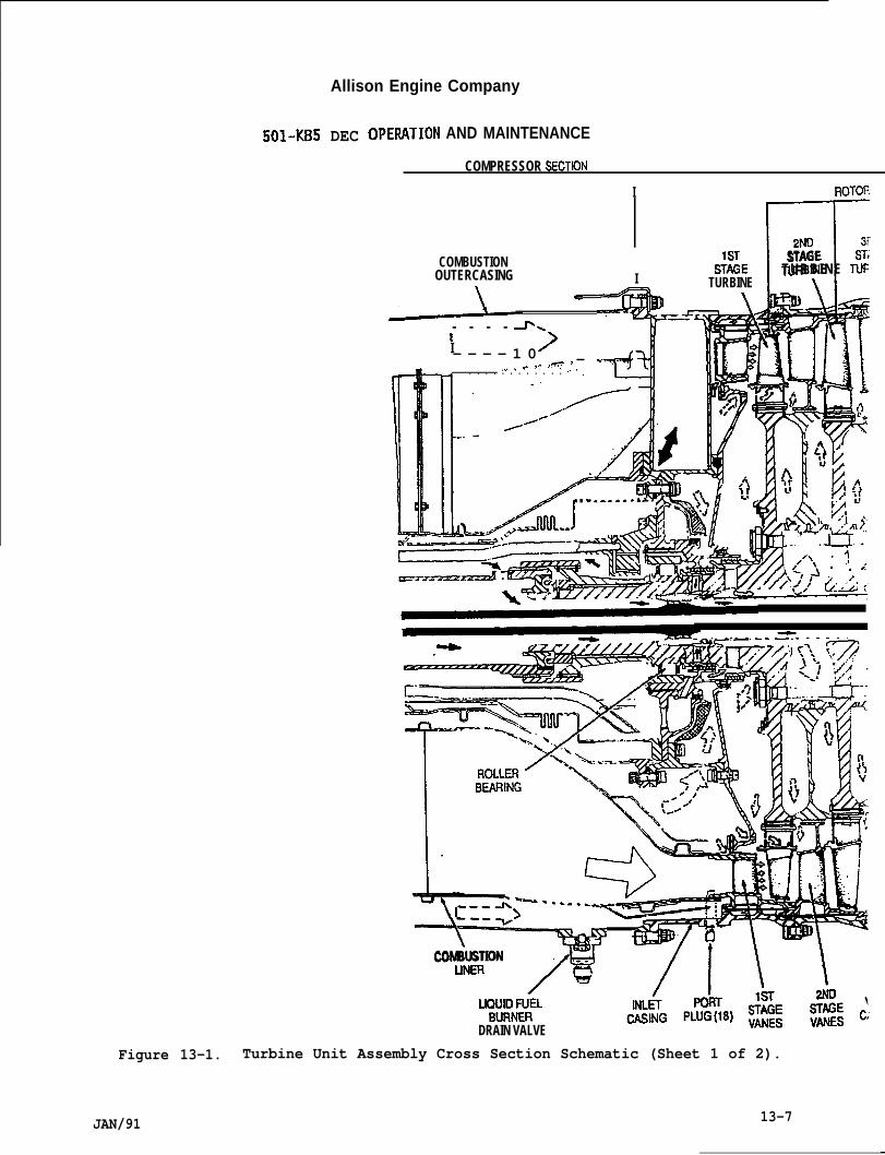
Allison Engine Company
Figure 13-1.
501-KB5 DEC OP‘ERATION AND MAINTENANCE
COMPRESSOR SECT~N
I ROTOFmFCOMBUSTION
I IISTAGE ST;
OUTERCASING S%E TURBINE TLKTURBINE
+
>. .Ai ‘- - - -
tI— - - - 1 0> — ,-,-,. % ~., *T ..- .“
~+ . . . . . . . . . . . . .. ,’. 3 )
-’TT---TyyA
COMBUSTION .#-- -/7\–\
LKXIOiiEL
DRAIN VALVE
Turbine Unit Assembly Cross Section Schematic (Sheet 1 of 2).
JAN/91 13-7
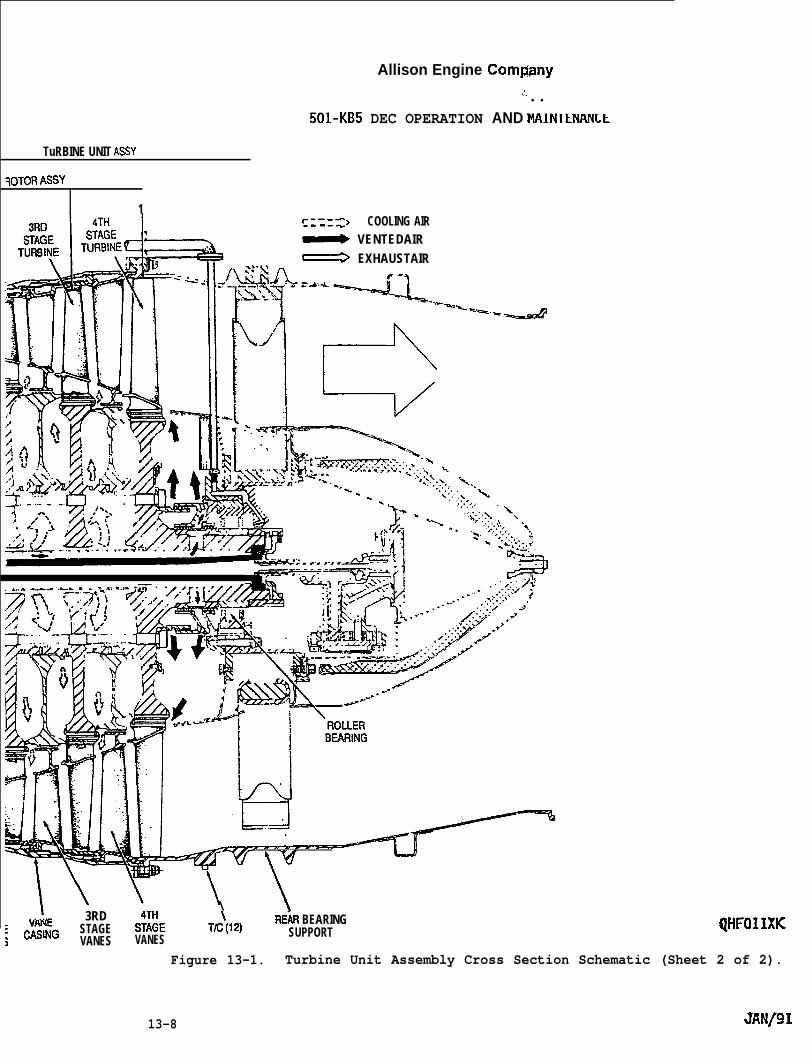
Allison Engine Com@my.!. . .
501-KB5 DEC OPERATION AND MAINltJWNLL
TuRBINE UNIT ASSY
<OTORASsy
1~-- .-r.>----+ COOLING AIR~ VENTEDAIR~ EXHAUSTAIR
‘“’’”<....<=‘“’d
e
%.., ”.\ \“..:.:.,, .
. . . . . . ..y,.:h ‘.. . ..-.. .*. “../..; .:.... ‘t~‘b ., -.:.,.
*& . . . . . .;~.s, .
.- --- :.. .
.vY1 3RD – -
\ \. . . ..-
S;;E TK\(12) REhR BEARING; c:’;G STAGE
VANES VANES SUPPORT
w
QHFOISXK
Figure 13-1. Turbine Unit Assembly Cross Section Schematic (Sheet 2 of 2).
13-8 JANf91

30
4.
5.
6.
7.
Allison Engine Company
501-KB5 DEC OPERATION AND MAINTENANCE
Remove leads from thermocouples (T\C) and junction block asoutlined in Section 5, Turb~ne O~t’le~ Temperature (TOT) System.
Remove nuts, bolts,Remove T/C harness.
Remove rear bearingpump’s oil lines asSystem.
and brackets which retain the T/C harness
scavenge oil pump and external scavenge ooutlined in Section 7, Engine Lubrication
1
Remove vibration pickup, other instrumentation devices, and leadswhich may interfere with removing turbine unit assembly or maybecome damaged during removal procedures.
Install compressor holder, 3755, on front of the compressor andretain with’ two nuts (Ref~ Figure 13-2).
NOTE
A 0.750 (3/4) inch ratchet or hinge handle may be used instead of aT-handle.
8. Remove lockring (1, Figure 13-3). Remove retaining nut (2) usingwrench support, 6796382, retaining nut wrench, 6796530, and a0.750 (3/4) inch T-handle (Ref. Figure 13-4).
COMPRESSOR‘HOLDER(3755)
QHT036XD
Figure 13-2. Compressor Holder, 3755.
JAN/91 13-9
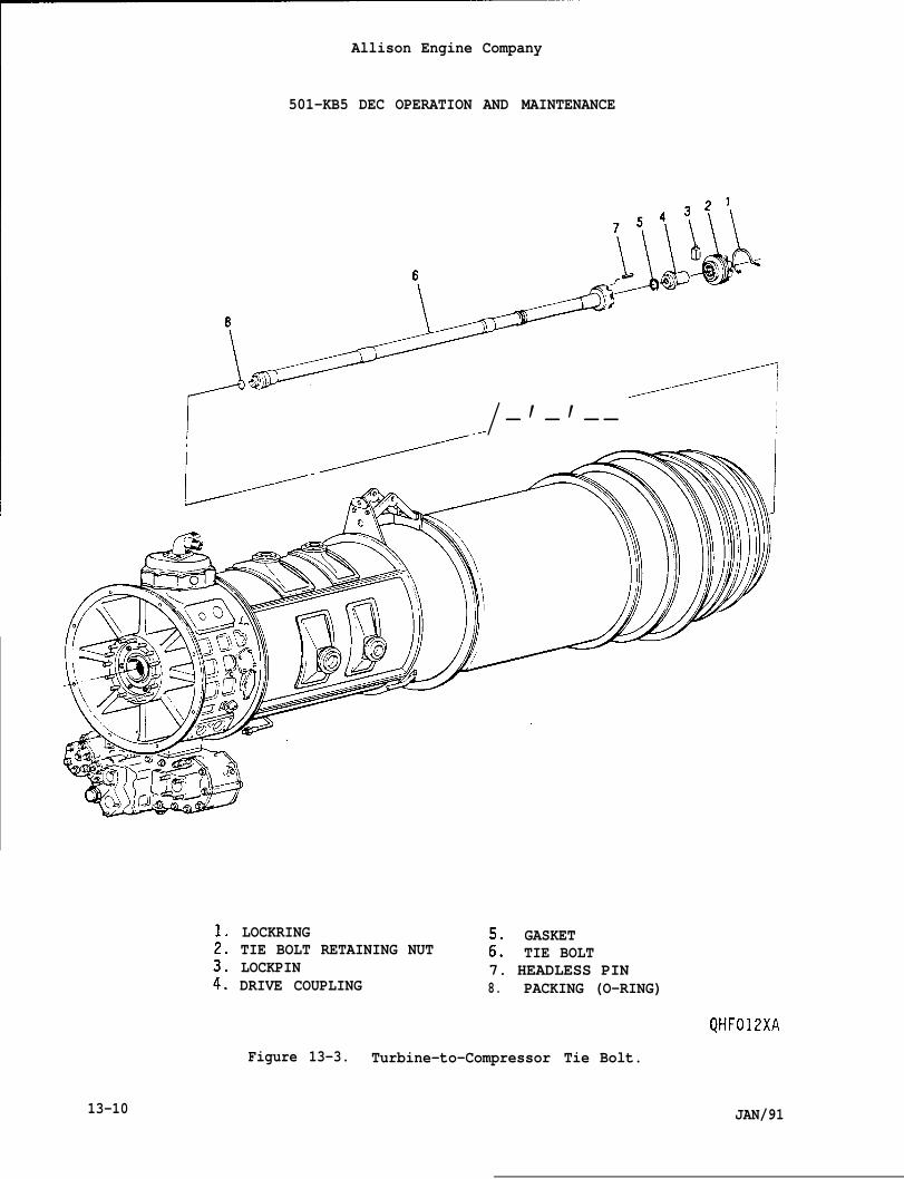
Allison Engine Company
501-KB5 DEC OPERATION AND MAINTENANCE
I /-’-’-- i
13-10
LOCKRING GASKETTIE BOLT RETAINING NUT ;: TIE BOLTLOCKPIN 7. HEADLESS PINDRIVE COUPLING 8. PACKING (O-RING)
QHF012XA
Figure 13-3. Turbine-to-Compressor Tie Bolt.
JAN/91
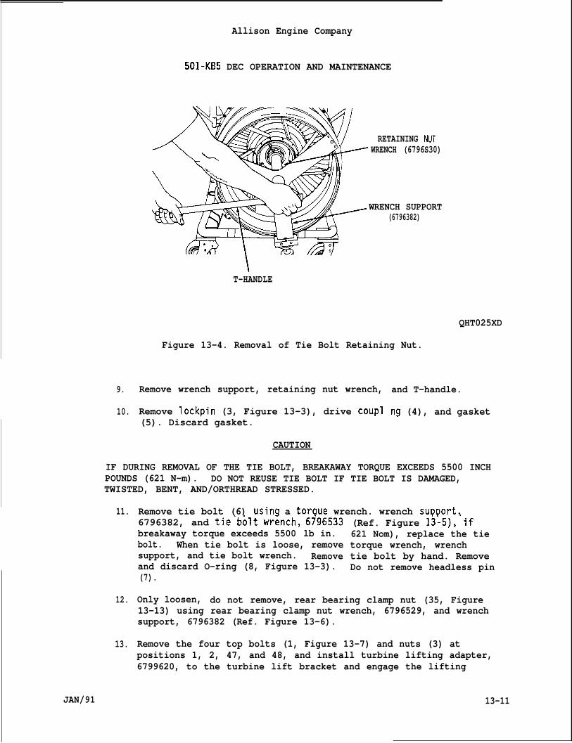
9.
10.
Allison Engine Company
501-KB5 DEC OPERATION AND MAINTENANCE
RETAINING NUTWRENCH (6796S30)
WRENCH SUPPORT(6796382)
T-HANDLE
QHT025XD
Figure 13-4. Removal of Tie Bolt Retaining Nut.
Remove wrench support, retaining nut wrench,
Remove lockpin (3, Figure 13-3), drive coupl
and T-handle.
ng (4), and gasket(5). Discard gasket.
CAUTION
IF DURING REMOVAL OF THE TIE BOLT, BREAKAWAY TORQUE EXCEEDS 5500 INCHPOUNDS (621 N-m). DO NOT REUSE TIE BOLT IF TIE BOLT IS DAMAGED,TWISTED, BENT, AND/ORTHREAD STRESSED.
11.
12.
13.
JAN/91
Remove tie bolt (6) usina a toraue wrench. wrench suDDort.6796382, and tie’bolt wr=nch, 6i96533breakaway torque exceeds 5500 lb in.bolt. When tie bolt is loose, removesupport, and tie bolt wrench. Removeand discard O-ring (8, Figure 13-3).(7).
(Ref. Figure 13:5),’if621 Nom), replace the tietorque wrench, wrenchtie bolt by hand. RemoveDo not remove headless pin
Only loosen, do not remove, rear bearing clamp nut (35, Figure13-13) using rear bearing clamp nut wrench, 6796529, and wrenchsupport, 6796382 (Ref. Figure 13-6).
Remove the four top bolts (1, Figure 13-7) and nuts (3) atpositions 1, 2, 47, and 48, and install turbine lifting adapter,6799620, to the turbine lift bracket and engage the lifting
13-11
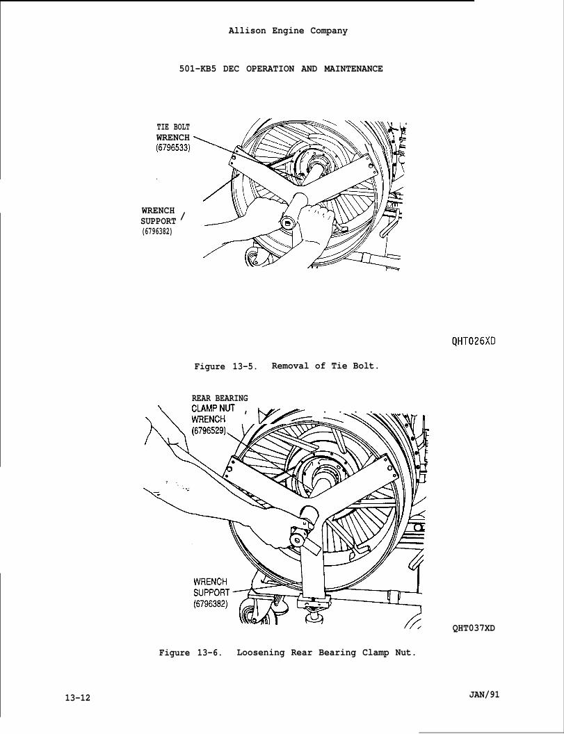
Allison Engine Company
501-KB5 DEC OPERATION AND MAINTENANCE
TIE BOLTWRENCH \\%&k
*?’.. \\\N\ \\ \\\\\\P
WRENCH /\\\\ \vlll/ 1
SUPPORT(6796382)
0
sL-
Figure 13-5. Removal of Tie Bolt.
REAR BEARING
\ \CL&f’#T , py-.i-.~ . . . .
%
7 -- .
\
- - -
-_
=*K!!r ET’
QHT037XD
Figure 13-6. Loosening Rear Bearing Clamp Nut.
13-12 JAN/91
●
●
Allison Engine Company
501-KB5 DEC OPERATION AND MAINTENANCE
adapter dowel pins into the removed bolt holes by screwing on thelifting adapter’s adjustment knob for a tight fit. Attach a hoistto the lifting adapter and remove the slack (weight) (Ref. Figure13-8) .
USE CARE WHEN REMOVINGAND A SLOW MOVEMENT TOOR DAMAGE MAY OCCUR.
CAUTION
TURBINE UNIT ASSEMBLY,REAR UNTIL IT IS CLEAR
NOTE
Record positions of slab head bolts, hex headinstallation.
KEEPING IT HORIZONTALLYOF OUTER COMBUSTION CASING
bolts, and brackets for
Hex head bolts are used for the two piece outer combustion casing.If a one piece outer combustion casing is installed, all are slab headbolts.
14. Remove slab head bolts (1, Figure 13-7), hex head bolts (2), nut(3), and brackets (4), and slowly pull the turbine unit assembly(22) to the rear to disengage it from the compressor, turbinecoupling shaft assembly (5), and to the outer combustion case (6).
15. Install the turbine unit assembly (22) horizontally in an engineturnover stand, 6797352, with the attaching stand adapter,6796644, clamping it to the forward rib of the turbine rearbearing support (Ref. Figure 13-9).
NOTE
Removal of the turbine coupling shaft assembly for inspection isallowed. Disassembly of the turbine coupling shaft assembly is notallowed at this Maintenance Level. The turbine coupling shaft assemblyrequires a high speed balance if it is disassembled.
16. If required, remove retaining ring (7, Figure 13-7) and turbinecoupling shaft assembly (5) from compressor diffuser forinspection.
17. Remove and
USE CAUTION WHENFORCE MAY DAMAGE
JAN/91
discard split seal rings (20) and O-rings (21).
CAUTION
PULLING TURBINE ROTOR ASSEMBLY TO THE REAR, EXCESSIVETHE TURBINE ROTOR ASSEMBLY AND/OR VANES.
13-13
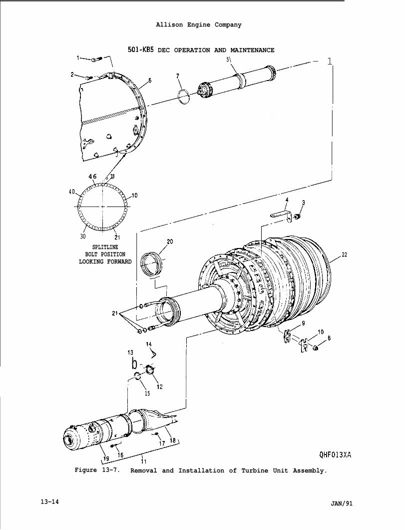
Allison Engine Company
501-KB5 DEC OPERATION AND MAINTENANCEl-fl~ 5\
/46 ,1
30 21
SPLITLINEBOLT POSITION
LOOKING FORWARD
./- 1
I
I
I4
22
b >./‘ec?’ ‘r\\215
QHF013XA
Figure 13-7. Removal and Installation of Turbine Unit Assembly.
13-14 JAN/91
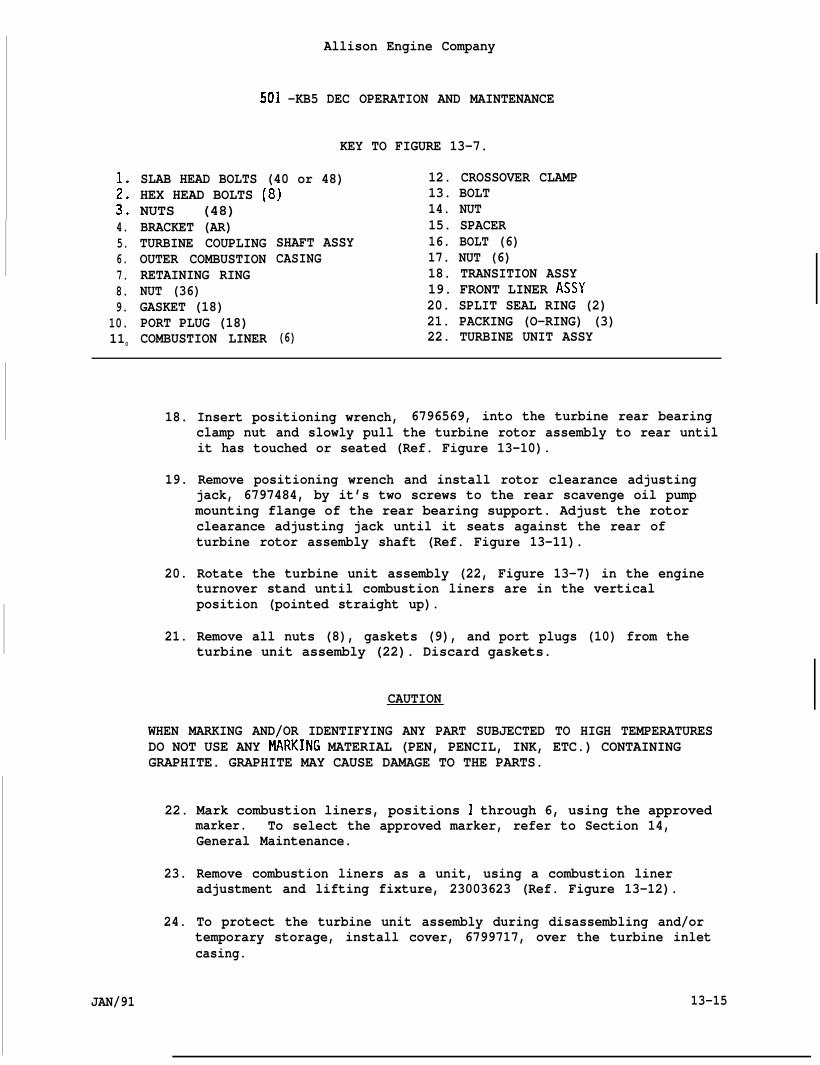
4.5.6.7.8.9.
10.110
Allison Engine Company
501 -KB5 DEC OPERATION AND MAINTENANCE
KEY TO FIGURE 13-7.
SLAB HEAD BOLTS (40 or 48) 12. CROSSOVER CLAMPHEX HEAD BOLTS (8) 13. BOLTNUTS (48) ‘BRACKET (AR)TURBINE COUPLINGOUTER COMBUSTIONRETAINING RINGNUT (36)GASKET (18)PORT PLUG (18)COMBUSTION LINER
.14. NUT15. SPACER
SHAFT ASSY 16. BOLT (6)CASING 17. NUT (6)
18. TRANSITION ASSY19. FRONT LINER ASSY20. SPLIT SEAL RING (2)21. PACKING (O-RING) (3)
(6) 22. TURBINE UNIT ASSY
18. Insert positioning wrench, 6796569, into the turbine rear bearingclamp nut and slowly pull the turbine rotor assembly to rear untilit has touched or seated (Ref. Figure 13-10).
19. Remove positioning wrench and install rotor clearance adjustingjack, 6797484, by it’s two screws to the rear scavenge oil pumpmounting flange of the rear bearing support. Adjust the rotorclearance adjusting jack until it seats against the rear ofturbine rotor assembly shaft (Ref. Figure 13-11).
20. Rotate the turbine unit assembly (22, Figure 13-7) in the engineturnover stand until combustion liners are in the verticalposition (pointed straight up).
21. Remove all nuts (8), gaskets (9), and port plugs (10) from theturbine unit assembly (22). Discard gaskets.
CAUTION
WHEN MARKING AND/OR IDENTIFYING ANY PART SUBJECTED TO HIGH TEMPERATURESDO NOT USE ANY tiRKING MATERIAL (PEN, PENCIL, INK, ETC.) CONTAININGGRAPHITE. GRAPHITE MAY CAUSE DAMAGE TO THE PARTS.
22. Mark combustion liners, positions 1 through 6, using the approvedmarker. To select the approved marker, refer to Section 14,General Maintenance.
23. Remove combustion liners as a unit, using a combustion lineradjustment and lifting fixture, 23003623 (Ref. Figure 13-12).
24. To protect the turbine unit assembly during disassembling and/ortemporary storage, install cover, 6799717, over the turbine inletcasing.
JAN/91 13-15
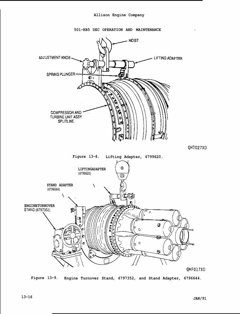
Allison Engine Company
501-KB5 DEC OPERATION AND MAINTENANCE
ADJ AP
Figure 13-8. Lifting Adapter, 6799620.
LIFTINGADAPTER
Q
Q(6799620)
\
@
STAND ADAPTER(6796644)
\
ENGINETURNOVERSTAND(679~52)
TER
.
QHT027XD
“( d“%QL
QHF017XD
Figure 13-9. Engine Turnover Stand, 6797352, and Stand Adapter, 6796644.
13-16 JAN/91
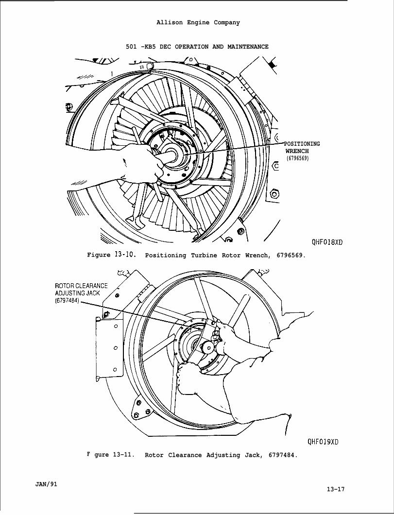
Allison Engine Company
501 -KB5 DEC OPERATION AND MAINTENANCE
POSITIONINGWRENCH(6796569)
Figure 13-10. Positioning Turbine Rotor Wrench, 6796569.
F
JAN/91
gure 13-11. Rotor Clearance Adjusting Jack, 6797484.
13-17
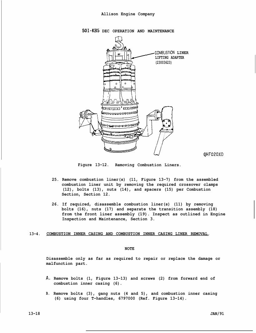
501-KB5
Allison Engine Company
DEC OPERATION AND MAINTENANCE
.COMBUSTION LINERLIFTING ADAPTER(23003623)
MH0 00 0
00
QHF020XD
Figure 13-12. Removing Combustion Liners.
25. Remove combustion liner(s) (11, Figure 13-7) from the assembledcombustion liner unit by removing the required crossover clamps(12), bolts (13), nuts (14), and spacers (15) per CombustionSection, Section 12.
26. If required, disassemble combustion liner(s) (11) by removingbolts (16), nuts (17) and separate the transition assembly (18)from the front liner assembly (19). Inspect as outlined in EngineInspection and Maintenance, Section 3.
13-4. COMBUSTION INNER CASING AND COMBUSTION INNER CASING LINER REMOVAL.
NOTE
Disassemble only as far as required to repair or replace the damage ormalfunction part.
A,
B.
13-18
Remove bolts (1, Figure 13-13) and screws (2) from forward end ofcombustion inner casing (6).
Remove bolts (3), gang nuts (4 and 5), and combustion inner casing(6) using four T-handles, 6797000 (Ref. Figure 13-14).
JAN/91
Allison Engine Company
501 -KB5 DEC OPERATION AND MAINTENANCE
C. Remove and discard O-ring (7, Figure 13-13) from the rear of thecombustion inner casing (6).
D. Remove and discard O-ring (9) from forward end of the combustioninner casing liner (11) (Ref. Figure 13-15).
E. Remove bolts (8, Figure 13-13) and combustion inner casing liner (11)from forward end of the turbine unit (34). Remove and discard seal(10) from the rear end of the combustion inner casing liner.
F. Remove bolts (12) and scavenge oil tube (13) from the forward end ofthe turbine unit (34).
G. Remove bolts (14) and the tube and nozzle assembly (15) from theforward end of the turbine unit (34).
H. If required for cleaning or maintenance, disassemble tube and nozzleassembly (15) as follows:
1. Bend locking tab down on the tab lockwasher (16), remove oilnozzle (17) and tab lockwasher from tube and nozzle assembly(15). Discard tab lockwasher.
2. Bend locking tab down on the tab lockwasher (18), remove taper oilnozzle (19) and tab lockwasher from tube and nozzle assembly(15). Discard tab lockwasher.
3. Clean, repair, or replace parts as required.
13-5. FRONT BEARING, FRONT BEARING SUPPORT, FRONT BEARING CAGE, AND FRONTBEARING LABYRINTH SEAL REMOVAL.
A. Remove lockring (20, Figure 13-13) from the turbine coupling clampnut (21) and inside of the turbine drive shaft.
B. Remove turbine coupling clamp nut (21) using a 0.750 (3/4) inchT-handle and clamp nut wrench, 6799621 (Ref. Figure 13-16).
C. Remove assembled shaft coupling (22, Figure 13-13) and shaft adapter(23) from turbine unit’s drive shaft. Separate shaft COUPI ing andshaft adapter by removing a retaining ring (24) and after separationremove remaining retaining ring (24).
D. Remove bearing’s (25) inner race and rollers using bearing removaltool, 6799902 (Ref. Figure 13-17).
E. Remove front bearing support (26, Figure 13-13) using threeT-handles, 6797000 (Ref. Figure 13-18).
JAN/91 13-19
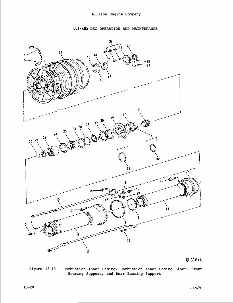
501-KB5 DEC OPERATION AND MAINTENANCE
/“”/’-’”
Allison Engine Company
JAN/91
I //--- 33 I
r+
\13
QHG16XA
Figure 13-13. Combustion Inner Casing, Combustion Inner Casing Liner, FrontBearing Support, and Rear Bearing Support.
13-20
;:3.4.5.6.7.8.9.
10.11.12.13.14.15.16.17.18.19.20.
i23.
BOLTSCREWB O LT
10)(4)241
Allison Engine Company
501-KB5 DEC OPERATION AND MAINTENANCE
KEY TO FIGURE 13-13
GANG NUT’GANG NUT (5)COMBUSTION INNER CASINGPACKING (O-RING)BOLT (24)PACKING (O-RING)SEALCOMBUSTION INNER CASINGBOLT (2)SCAVENGE OIL TUBEBOLT (2)TUBE AND NOZZLE ASSYTAB LOCKWASHEROIL NOZZLETAB LOCKWASHERTAPERED OIL NOZZLELOCKRING
24.25.26.27.28.29.30.31.32.33.
LINER 34.35.36.37.38.39,40,41,42.43,
TURBINE COUPLING CLAMP NUT 44.SHAFT COUPLING 45.SHAFT ADAPTER 46.
RETAINING RING (2)BEARING (NO. 3)FRONT BEARING SUPPORTFRONT BEARING CAGEINTERNAL RETAINING RINGOUTER RETAINING RINGFRONT BEARING VIBRATION DAMPERSPLIT SEAL RINGSPLIT SEAL RINGFRONT LABYRINTH SEALTURBINE UNITREAR BEARING CLAMP NUTSHORT BOLT (2)LONG BOLT (7)REAR BEARING RETAINEROIL NOZZLETAB LOCKWASHERRETAINERLOCKING KEYREAR BEARING (NO.4)METALLIC O-RING SEALMETALLIC O-RING SEALREAR BEARING CAGE
F.
G.
H.
JAN/91
If required, remove internal retaining ring (28, Figure 13-13) fromfront of bearing cage (27) and remove bearing (25) outer race usingfront bearing outer race puller, 6799642 (Ref. Figure 13-19) asfollows:
1. Loosen nut from pin lock enough to allow guide pins and jaws to bemoved fully inboard.
2. Loosen nut on tension bolt to ensure clearance.
3. Pass tension bolt into front bearing cage and engage jaws behindbearing outer race. Tighten pin lock to hold guide pins and jawsoutboard in the guide pin plate, locking jaws behind bearing outerrace.
4. Tighten nut on tension bolt and remove bearing’s (25, Figure13-13) outer race.
If required, remove external retaining ring (29, Figure 13-13) andseparate front bearing support (26) and front bearing cage (27).Remove front bearing vibration damper (30).
If required, remove and discard split seal rings (31 and 32) fromfront bearing cage (27).
13-21
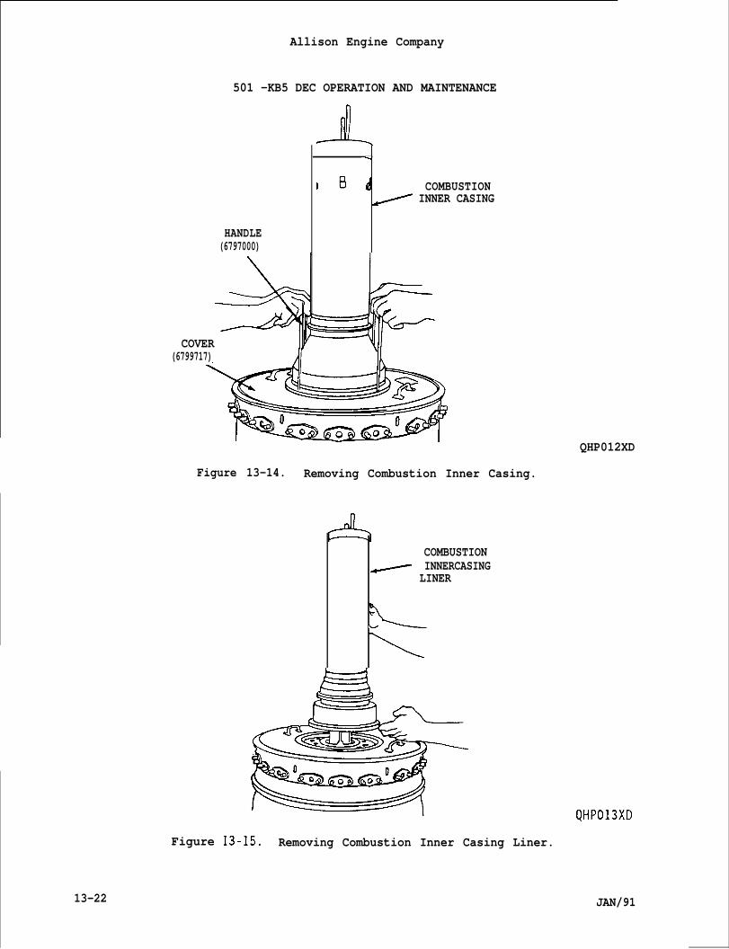
13-22
Allison Engine Company
501 -KB5 DEC OPERATION AND MAINTENANCE
HANDLE(6797000)
\
,B d COMBUSTION~ INNER CASING
COVER(6799717) Jf 1
QHP012XD
Figure 13-14. Removing Combustion Inner Casing.
COMBUSTIONINNERCASING
~ LINER
eu
Figure 13-15. Removing Combustion Inner Casing Liner.
QHP013XD
JAN/91
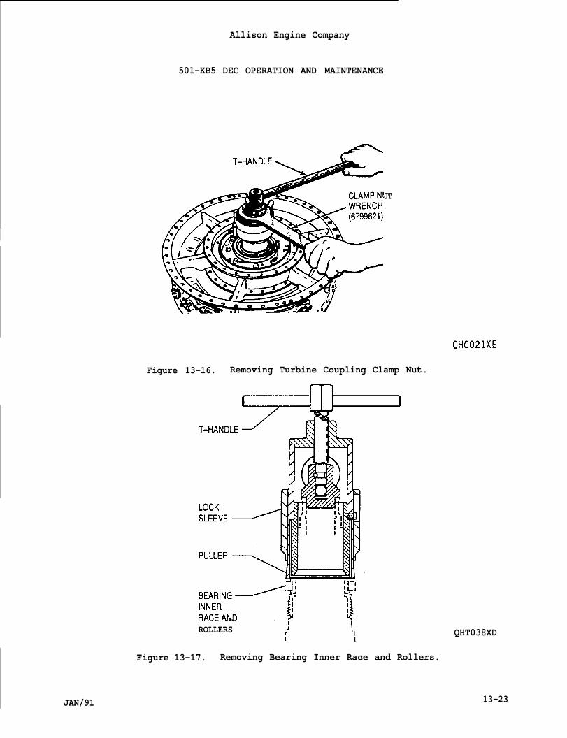
I
JAN/91
Allison Engine Company
501-KB5 DEC OPERATION AND MAINTENANCE
JT
QHG021XE
Figure 13-16. Removing Turbine Coupling Clamp Nut.
ROLLERSI; \
1f I
QHT038XD
Figure 13-17. Removing Bearing Inner Race and Rollers.
13-23
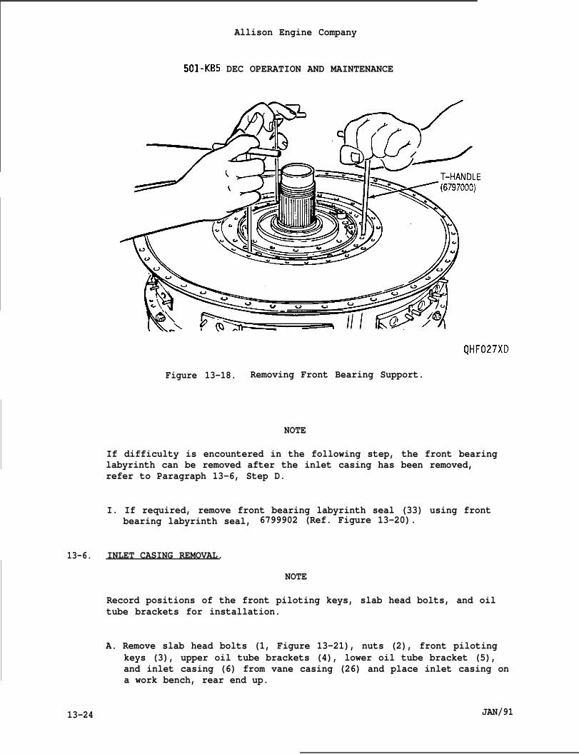
Allison Engine Company
501-KB5 DEC OPERATION AND MAINTENANCE
QHF027XD
Figure 13-18. Removing Front Bearing Support.
NOTE
If difficulty is encountered in the following step, the front bearinglabyrinth can be removed after the inlet casing has been removed,refer to Paragraph 13-6, Step D.
I. If required, remove front bearing labyrinth seal (33) using frontbearing labyrinth seal, 6799902 (Ref. Figure 13-20).
13-6. INLET CASING REMOVAL.
NOTE
Record positions of the front piloting keys, slab head bolts, and oiltube brackets for installation.
A. Remove slab head bolts (1, Figure 13-21), nuts (2), front pilotingkeys (3), upper oil tube brackets (4), lower oil tube bracket (5),and inlet casing (6) from vane casing (26) and place inlet casing ona work bench, rear end up.
13-24 JAN/91
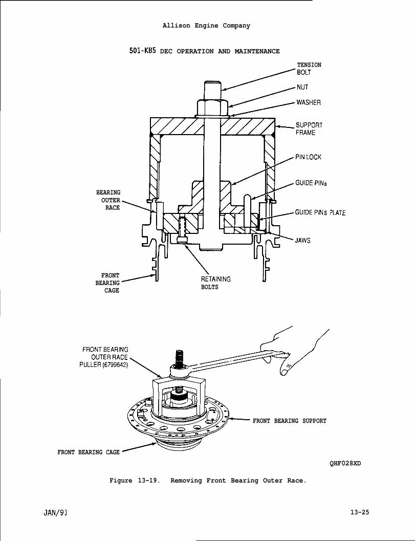
Allison Engine Company
501-KB5 DEC OPERATION AND MAINTENANCE
TENSION
sBEARINGOUTERRACE
S P1.
FRONTBEARING
CAGE BOLTS
.ATE
FRONT BEARING CAGE
FRONT BEARING SUPPORT
QHF028XD
Figure 13-19. Removing Front Bearing Outer Race.
13-25
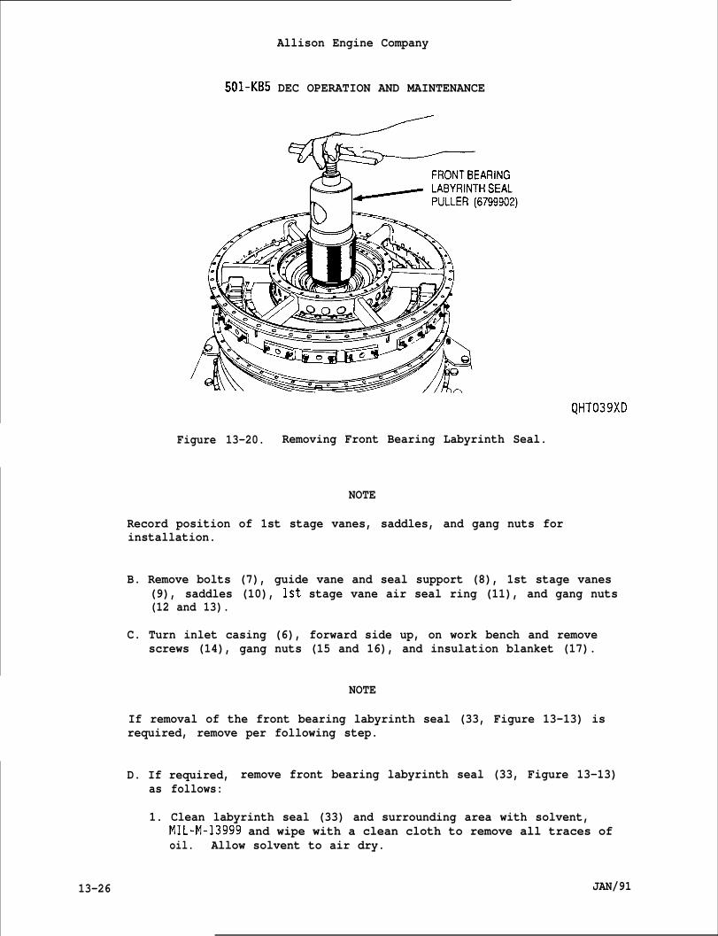
Allison Engine Company
501-KB5 DEC OPERATION AND MAINTENANCE
QHT039XD
Figure 13-20. Removing Front Bearing Labyrinth Seal.
NOTE
Record position of 1st stage vanes, saddles, and gang nuts forinstallation.
B. Remove bolts (7), guide vane and seal support (8), 1st stage vanes(9), saddles (10), 1st stage vane air seal ring (11), and gang nuts(12 and 13).
C. Turn inlet casing (6), forward side up, on work bench and removescrews (14), gang nuts (15 and 16), and insulation blanket (17).
NOTE
If removal of the front bearing labyrinth seal (33, Figure 13-13) isrequired, remove per following step.
D. If required, remove front bearing labyrinth seal (33, Figure 13-13)as follows:
1. Clean labyrinth seal (33) and surrounding area with solvent,MIL-M-13999 and wipe with a clean cloth to remove all traces ofoil. Allow solvent to air dry.
13-26 JAN/91
●
●
Allison Engine Company
501-KB5 DEC OPERATION AND MAINTENANCE
WARNING
MAKE SURE SOLVENT IS DRY BEFORE HEAT IS APPLIED. INJURY TO PERSONNELAND/OR DAMAGE MAY OCCUR.
CAUTION
DO NOT CONCENTRATE HEAT IN ONE AREA, HEAT MUST BE KEPT MOVING OR DAMAGEMAY OCCUR.
NOTE
Steps 2 and 3 should be done as quickly as possible, not allowinglabyrinth seal to cool.
2. Cover turbine rotor assembly with a suitable fire blanket. Heatforward bearing labyrinth seal (33), using propane or butanetorch, moving the torch around the labyrinth seal. Heating shouldrequire approximately three (3) minutes.
3. Install turbine front bearing labyrinth seal puller, 6799902,engaging clam shell flange in a slot in the labyrinth seal.Remove labyrinth seal (Ref. Figure 13-22).
4. Remove fire blanket.
NOTE
Use front labyrinth seal puller, 6799623, the same as front bearinglabyrinth seal puller, 6799902, refer to Figure 13-20.
If difficult is encountered in the followin~ step, use heat and therotor front labyrinth seal puller, 6799623, & per’the prior Step D.
E. If required, remove snapring (18, Figure 13-21) and then remove rotorfront labyrinth seal (19) using the rotor front labyrinth sealpuller, 6799623, from rotor assembly (32) shaft.
13-7. VANE CASING AND 2ND. 3RD, 4TH VANES REMOVAL.
A. Remove slab head bolts (20, Figure 13-21), nuts (21), lift bracket(22), and 2nd stage vane retainers (23).
B. Remove vane casing (26) from rear bearing support using fourT-handles, 6797000 (Ref. Figure 13-23).
JAN/91 13-27
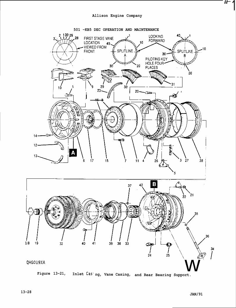
“--- 1Allison Engine Company
501 -KB5 DEC OPERATION AND MAINTENANCE
I
I!fi
231 ‘ / 20--T / 2
i ___ I II I-@
18 19 32
QHG019XA
Figure 13-21, Inlet Cas.w
ng, Vane Casing, and Rear Bearing Support.
13-28 JAN/91
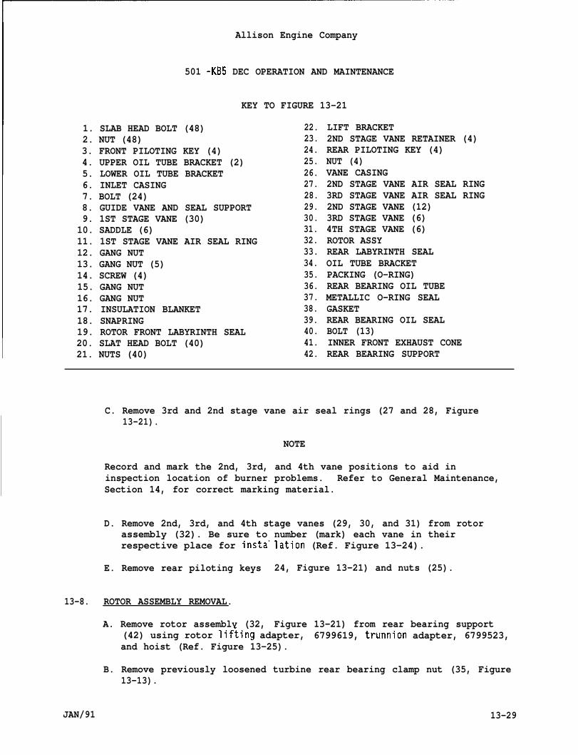
Allison Engine Company
501 -KB5 DEC OPERATION AND MAINTENANCE
KEY TO FIGURE 13-21
1. SLAB HEAD BOLT (48)2. NUT (48)3. FRONT PILOTING KEY (4)4. UPPER OIL TUBE BRACKET (2)5. LOWER OIL TUBE BRACKET6. INLET CASING7. BOLT (24)8. GUIDE VANE AND SEAL SUPPORT9. 1ST STAGE VANE (30)10. SADDLE (6)11. 1ST STAGE VANE AIR SEAL RING12. GANG NUT13. GANG NUT (5)14. SCREW (4)15. GANG NUT16. GANG NUT17. INSULATION BLANKET18. SNAPRING19. ROTOR FRONT LABYRINTH SEAL20. SLAT HEAD BOLT (40)21. NUTS (40)
22.23.24.25.26.27.28.29.30.31.32.33.34.35.36.37.38.39.40.41.42.
LIFT BRACKET2ND STAGE VANE RETAINER (4)REAR PILOTING KEY (4)NUT (4)VANE CASING2ND STAGE VANE AIR SEAL RING3RD STAGE VANE AIR SEAL RING2ND STAGE VANE (12)3RD STAGE VANE (6)4TH STAGE VANE (6)ROTOR ASSYREAR LABYRINTH SEALOIL TUBE BRACKETPACKING (O-RING)REAR BEARING OIL TUBEMETALLIC O-RING SEALGASKETREAR BEARING OIL SEALBOLT (13)INNER FRONT EXHAUST CONEREAR BEARING SUPPORT
C. Remove 3rd and 2nd stage vane air seal rings (27 and 28, Figure13-21).
NOTE
Record and mark the 2nd, 3rd, and 4th vane positions to aid ininspection location of burner problems. Refer to General Maintenance,Section 14, for correct marking material.
D. Remove 2nd, 3rd, and 4th stage vanes (29, 30, and 31) from rotorassembly (32). Be sure torespective place for insta”
E. Remove rear piloting keys
13-8. ROTOR ASSEMBLY REMOVAL.
A. Remove rotor assembly (32,
number (mark) each vane in theirlation (Ref. Figure 13-24).
24, Figure 13-21) and nuts (25).
Figure 13-21) from rear bearing support(42) using rotor lif~ing adapter, 6799619, trunnion adapter, 6799523,and hoist (Ref. Figure 13-25).
B. Remove previously loosened turbine rear bearing clamp nut (35, Figure13-13).
JAN/91 13-29
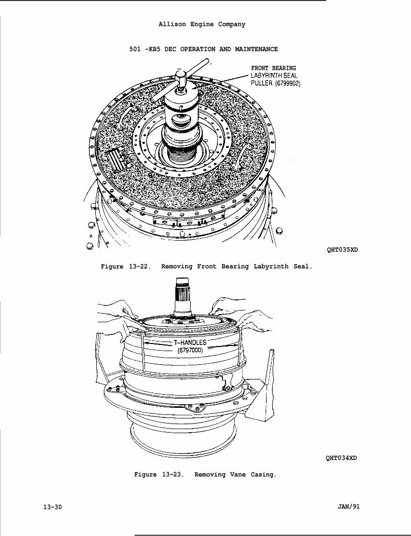
Allison Engine Company
501 -KB5 DEC OPERATION AND MAINTENANCE
— /7 FRONT BEARING
QHT035XD
Figure 13-22. Removing Front Bearing Labyrinth Seal.
/F--
Figure 13-23. Removing Vane
QHT034XD
Casing.
JAN/9113-30
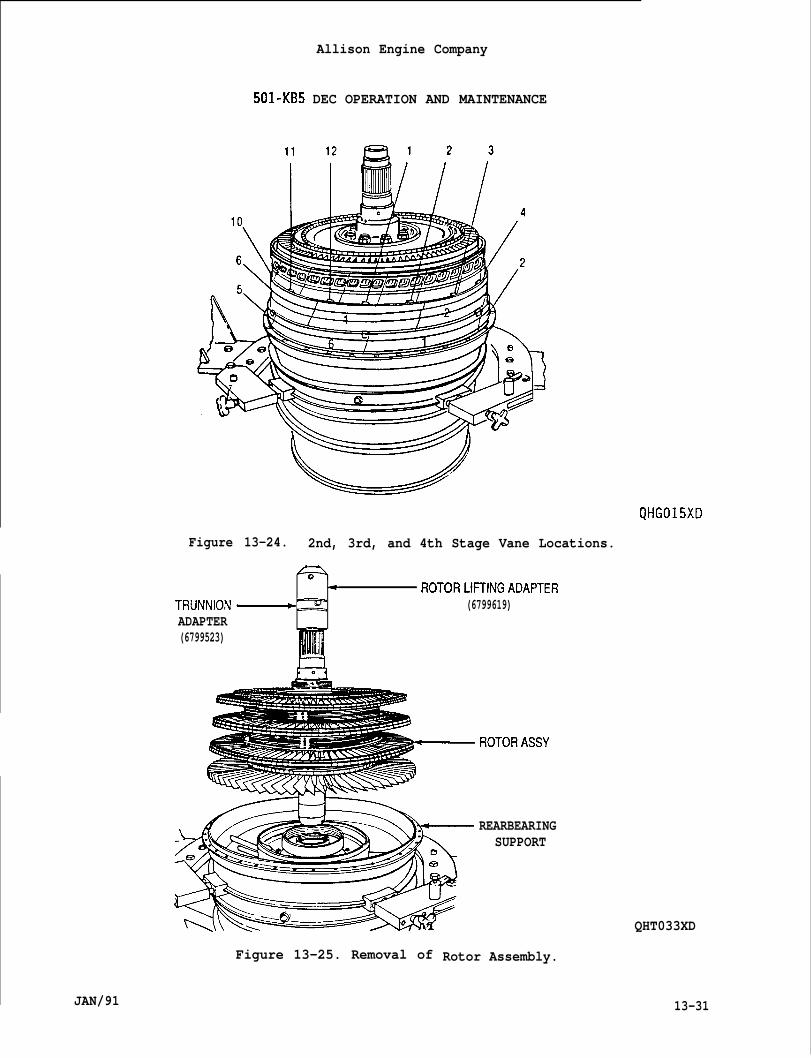
Allison Engine Company
501-KB5 DEC OPERATION AND MAINTENANCE
QHG015XD
Figure 13-24. 2nd, 3rd, and 4th Stage Vane Locations.
4P’+ ROTORLIFFINGADAPTERTRUNNION~z (6799619)ADAPTER(6799523)
pil!J‘;
ROTORASSY
Figure 13-25. Removal of
JAN/91
REARBEARINGSUPPORT
QHT033XD
Rotor Assembly.
13-31
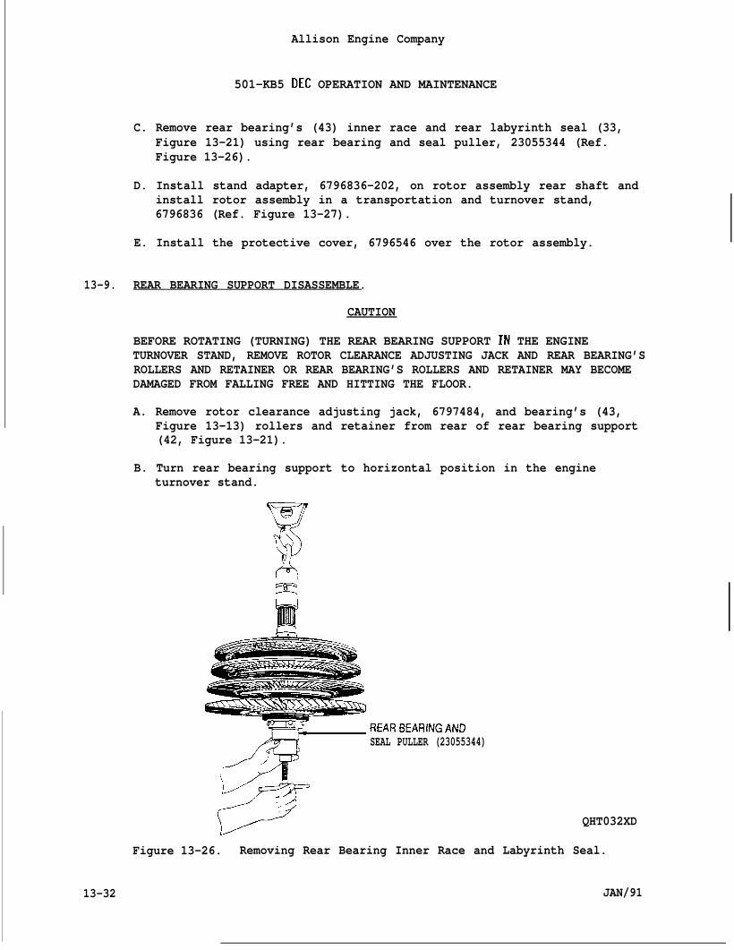
Allison Engine Company
501-KB5 DEC OPERATION AND MAINTENANCE
C. Remove rear bearing’s (43) inner race and rear labyrinth seal (33,Figure 13-21) using rear bearing and seal puller, 23055344 (Ref.Figure 13-26).
D. Install stand adapter, 6796836-202, on rotor assembly rear shaft andinstall rotor assembly in a transportation and turnover stand,6796836 (Ref. Figure 13-27).
E. Install the protective cover, 6796546 over the rotor assembly.
13-9. REAR BEARING SUPPORT DISASSEMBLE.
CAUTION
BEFORE ROTATING (TURNING) THE REAR BEARING SUPPORT IN THE ENGINETURNOVER STAND, REMOVE ROTOR CLEARANCE ADJUSTING JACK AND REAR BEARING’SROLLERS AND RETAINER OR REAR BEARING’S ROLLERS AND RETAINER MAY BECOMEDAMAGED FROM FALLING FREE AND HITTING THE FLOOR.
A. Remove rotor clearance adjusting jack, 6797484, and bearing’s (43,Figure 13-13) rollers and retainer from rear of rear bearing support(42, Figure 13-21).
B. Turn rear bearing support to horizontal position in the engineturnover stand.
1---
/ ‘9
REARBEARINGANDSEAL PULLER (23055344)
QHT032XD
Figure 13-26. Removing Rear Bearing Inner Race and Labyrinth Seal.
13-32 JAN/91
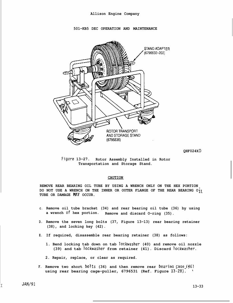
Allison Engine Company
501-KB5 DEC OPERATION AND MAINTENANCE
“ER
QHF024X
Figure 13-27. Rotor Assembly Installed in RotorTransportation and Storage Stand.
CAUTION
REMOVE REAR BEARING OIL TUBE BY USING A WRENCH ONLY ON THE HEX PORTIONDO NOT USE A WRENCH ON THE INNER OR OUTER FLANGE OF THE REAR BEARING OTUBE OR DAMAGE MAY OCCUR.
c.
D.
E.
F.
D
iL
Remove oil tube bracket (34) and rear bearing oil tube (36) by usinga wrench of hex portion. Remove and discard O-ring (35).
Remove the seven long bolts (37, Figure 13-13) rear bearing retainer(38), and locking key (42).
If required, disassemble rear bearing retainer (38) as follows:
1. Bend locking tab down on tab lockwasher (40) and remove oil nozzle(39) and tab Iockwasher from retainer (41). Discard lockwasher.
2. Repair, replace, or clear as required.
Remove two short bolts (36) and then remove rear bearina caae (46)
I JAN/91
using rear bearing cage-puller, 6796531 (Ref. Figure 13~28)~ ‘ ‘
13-33
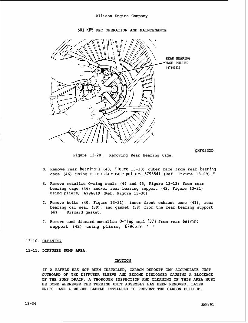
Allison Engine Company
501-KB5 DEC OPERATION AND MAINTENANCE
G.
H.
I.
J.
REAR BEARINGCAGE PULLER(6796531)
Figure 13-28. Removing Rear BearingQHF023XD
Cage.
Remove rear bearinq’s (43, Fiqure 13-13) outer race from rear bearinacage (46) using re~r outer ra;e puller,’6796541 (Ref. Figure 13-29).”
Remove metallic O-ring seals (44 and 45, Figure 13-13) from rearbearing cage (46) and/or rear bearing support (42, Figure 13-21)using pliers, 6796619 (Ref. Figure 13-30).
Remove bolts (40, Figure 13-21), inner front exhaust cone (41), rearbearing oil seal (39), and gasket (38) from the rear bearing support(42) . Discard gasket.
Remove and discard metallic O-rinq seal (37) from rear bearinqsupport (42) using pliers, 6796613. ‘ ‘
13-10. CLEANING.
13-11. DIFFUSER SUMP AREA.
CAUTION
IF A BAFFLE HAS NOT BEEN INSTALLED, CARBON DEPOSIT CAN ACCUMULATE JUSTOUTBOARD OF THE DIFFUSER SLEEVE AND BECOME DISLODGED CAUSING A BLOCKAGEOF THE SUMP DRAIN. A THOROUGH INSPECTION AND CLEANING OF THIS AREA MUSTBE DONE WHENEVER THE TURBINE UNIT ASSEMBLY HAS BEEN REMOVED. LATERUNITS HAVE A WELDED BAFFLE INSTALLED TO PREVENT THE CARBON BUILDUP.
13-34 JAN/91
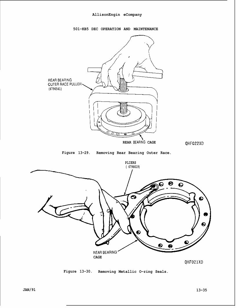
501-KB5 DEC OPERATION AND MAINTENANCE
AllisonEngin eCompany
?‘-)
\\
(
REARBEAI?INGC)UTERRACEPULLER(6796541)
Figure
REAR BEARltiG CAGE
13-29. Removing Rear Bearing Outer Race.
PLIERS( 6796619)
JAN/91
CAGEQHF021XD
Figure 13-30. Removing Metallic O-ring Seals.
13-35
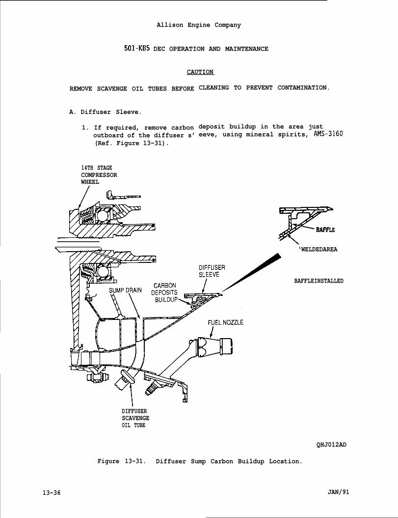
Allison Engine Company
501-KB5 DEC OPERATION AND MAINTENANCE
CAUTION
REMOVE SCAVENGE OIL TUBES BEFORE
A. Diffuser Sleeve.
1. If required, remove carbonoutboard of the diffuser s’(Ref. Figure 13-31).
14TH STAGECOMPRESSORWHEEL
CLEANING TO PREVENT CONTAMINATION.
deposit buildup in the area justeeve, using mineral spirits, AMS-3160
FBAFFLE
‘WELDEDAREA
BAFFLEINSTALLED
I NDIFFUSERSCAVENGEOIL TUBE
QHJ012AD
Figure 13-31. Diffuser Sump Carbon Buildup Location.
13-36 JAN/91
13-12.
13-13.
Allison Engine Company
501-KB5 DEC OPERATION AND MAINTENANCE
2. If required, inspect baffle and welded area for damage, noneallowed.
3. Clean area thoroughly, using mineral spirits, AMS-3160.
B. Diffuser, Diffuser Drain, and Drain Tubes.
NOTE
Do not reinstall oil tubes until complete cleaning is done.
1. Remove and clean bothspirits, AMS-3160.
2. Clean sump area, sumpspirits, AMS-3160.
diffuser scavenge oil tubes, using mineral
drain and sump drain tubes using mineral
TURBINE UNIT ASSEMBLY COMPONENTS.
Bearinas {No. 3 and No. 4).
ANY BEARING REMOVED BY PULLING OR PUSHING ON THE ROLLERS WILL RESULT INA LOAD TRANSFER THROUGH THE ROLLERS. IF THIS OCCURS THE BEARING MATCHEDSET(S) SHOULD BE REJECTED AND REPLACED.
JAN/91 13-37
BEARINGS INNER RACE, OUTER RACE, AND ROLLERS ARE A MATCHED SET. DAMAGETO ANY PART WILL REQUIRE COMPLETE BEARING REPLACEMENT. BEARING MUST BERETAINED AS A MATCHED SET.
A. Cleaning.
1. Immerse bearing in mineral spirminutes.
CAUTION
DO NOT SPIN BEARINGS HITHAIR BLAST.
ts, AMS-3160, or equivalent for 10
DAMAGE TO ROLLERS MAY OCCUR.
2. Dry bearing with filtered, compressed air, while holding rollersto prevent spinning.
B. Inspection.
CAUTION
Allison Engine Company
501-KB5 DEC OPERATION AND MAINTENANCE
1. Inspect bearing for roughness, pitting, denting, abrasion, nicks,wear, spalling, flaking, brinelling, cracks, skidding, etc.
2. Replace complete bearing matched set if any of the above damagesare found.
C. Preservation.
1. Bearing may be immersed and left in clean engine lube oil for upto 30 days storage.
NOTE
~ Storage may be made using plastic bags or other protective wrappings.
2. Immerse bearing in clean engine lube oil and wrap the bearing inglassine paper with the waxed side against the bearing. Secureglassine paper to ensure a dust-tight seal using tape. Thisstorage is also good for up to 30 days.
3. Storage more than 30 days:
a. Clean bearing prior to Step A.
b. Immerse bearing in clean corrosion preventive compoundpetrolatum, MIL-C-11796A, Class 3, heated at 165-175°F(74-79”C). Move bearing up and down to ensure the firstcongealed coating melts off and the bearings have an oilyappearance. Allow bearing to cool to less than lOO°F (38”C).
NOTE
Storage may be made using plastic bags or other protective wrappings.
c. Wrap bearing in glassine paper with the waxed side against thebearing. Secure glassine paper to ensure a dust-tight seal.
13-14. Inlet Casinq, Vane Casinq, Vanes, and Rear Bearincl Support.
13-38
CAUTION
DO NOT CLEAN FLAME PLATED PARTS (SUCH ASALKALINE RUST REMOVER SOLUTIONS. DAMAGE
THE BEARING CAGES) USINGTO FLAME PLATED AREA MAY OCCUR.
JAN/91
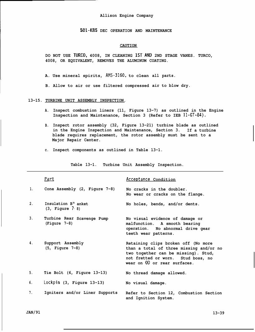
501-KB5
Allison Engine Company
DEC OPERATION AND MAINTENANCE
CAUTION
DO NOT USE TURCO, 4008, IN CLEANING lSTAND 2ND STAGE VANES. TURCO,4008, OR EQUIVALENT, REMOVES THE ALUMINUM COATING.
A. Use mineral spirits, AMS-3160, to clean
B. Allow to air or use filtered compressed
13-15. TURBINE UNIT ASSEMBLY INSPECTION.
all parts.
air to blow dry.
A.
B.
c.
Inspect combustion liners (11, Figure 13-7) as outlined in the EngineInspection and Maintenance, Section 3 (Refer to IEB 11-GT-84).
Inspect rotor assembly (32, Figure 13-21) turbine blade as outlinedin the Engine Inspection and Maintenance, Section 3. If a turbineblade requires replacement, the rotor assembly must be sent to aMajor Repair Center.
Inspect components as outlined in Table 13-1.
Table 13-1. Turbine Unit Assembly Inspection.
1.
2.
3.
4.
5.
6.
7.
~
Cone Assembly (2, Figure 7-8)
Insulation B“(3, Figure 7
Turbine Rear(Figure 7-8)
anket8)
Scavenge Pump
Support Assembly(5, Figure 7-8)
Tie Bolt (6, Figure 13-13)
Lockpin (3, Figure 13-13)
Igniters and/or Liner Supports
Accet)tance Condition
No cracks in the doubler.No wear or cracks on the flange.
No holes, bends, and/or dents.
No visual evidence of damage ormalfunction. A smooth bearingoperation. No abnormal drive gearteeth wear patterns.
Retaining clips broken off (No morethan a total of three missing and/or notwo together can be missing). Stud,not fretted or worn. Stud boss, nowear on OD or rear surfaces.
No thread damage allowed.
No visual damage.
Refer to Section 12, Combustion Section
JAN/91
and Ignition System.
13-39
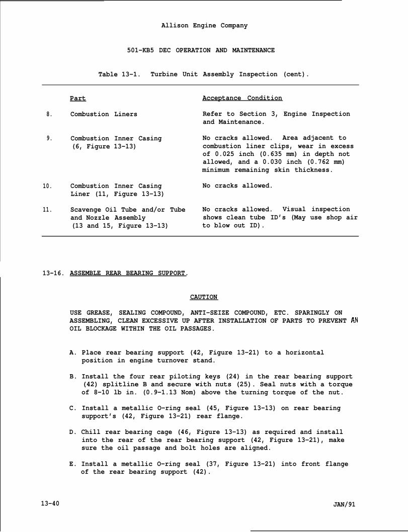
Allison Engine Company
501-KB5 DEC OPERATION AND MAINTENANCE
Table 13-1. Turbine Unit Assembly Inspection (cent).
Part
8. Combustion Liners
9. Combustion Inner Casing(6, Figure 13-13)
10. Combustion Inner CasingLiner (11, Figure 13-13)
11. Scavenge Oil Tube and/or Tubeand Nozzle Assembly(13 and 15, Figure 13-13)
Acceptance Condition
Refer to Section 3, Engine Inspectionand Maintenance.
No cracks allowed. Area adjacent tocombustion liner clips, wear in excessof 0.025 inch (0.635 mm) in depth notallowed, and a 0.030 inch (0.762 mm)minimum remaining skin thickness.
No cracks allowed.
No cracks allowed. Visual inspectionshows clean tube ID’s (May use shop airto blow out ID).
13-16.
13-40
ASSEMBLE REAR BEARING SUPPORT.
CAUTION
USE GREASE, SEALING COMPOUND, ANTI-SEIZE COMPOUND, ETC. SPARINGLY ONASSEMBLING, CLEAN EXCESSIVE UP AFTER INSTALLATION OF PARTS TO PREVENT ANOIL BLOCKAGE WITHIN THE OIL PASSAGES.
A. Place rear bearing support (42, Figure 13-21) to a horizontalposition in engine turnover stand.
B. Install the four rear piloting keys (24) in the rear bearing support(42) splitline B and secure with nuts (25). Seal nuts with a torqueof 8-10 lb in. (0.9-1.13 Nom) above the turning torque of the nut.
C. Install a metallic O-ring seal (45, Figure 13-13) on rear bearingsupport’s (42, Figure 13-21) rear flange.
D. Chill rear bearing cage (46, Figure 13-13) as required and installinto the rear of the rear bearing support (42, Figure 13-21), makesure the oil passage and bolt holes are aligned.
E. Install a metallic O-ring seal (37, Figure 13-21) into front flangeof the rear bearing support (42).
JAN/91
Allison Engine Company
501-KB5 DEC OPERATION AND MAINTENANCE
F. Install a gasket (38) on the rear face of the rear bearing oil seal(39) . Hold gasket in place with grease, VV-P-236. Lubricate ID ofrear bearing oil seal with anti-seize compound (Never-Seize), NS-165.
G. Install rear bearing oil seal (39) on the front face of the rearbearing support, make sure the oil passage and bolt holes arealigned.
H. Apply anti-seize (Never-Seize), NS-165, to the short bolts (36,Figure 13-13) and install the short bolts through the rear of therear bearing cage (46) to the rear bearing oil seal (39, Figure13-21), making sure the oil passage and bolt holes are aligned. Snugup the bolts just enough to hold parts in place.
NOTE
Steps I. and J. are done as one continuous Step.
I. Install O-ring (35) on rear bearing oil tube (36) and then apply asealing compound (Permatex, No. 1372 or 3M, EC-776) to the threads ofthe rear bearing oil tube. Install rear bearing oil tube in the rearbearing support (42).
J. Install oil tube bracket (34) and retain by two bolts and nuts.Torque rear bearing oil tube (36) to 250-300 lb in. (28.25-33.90N-m), aligning rear bearing oil tube and oil tube bracket. Removeoil tube bracket and lockwire rear bearing oil tube.
K. Install inner front exhaust cone (41) and secure to the front of therear bearing support (42) with bolts (40). Torque bolts to 35-40 lbin. (4.O-4.5N”m) and lockwire.
CAUTION
THE BEARING’S INNER RACE, OUTER RACE, AND ROLLER ARE ANATCHED SET WITHPART NUMBER AND SERIAL NUMBER LOCATED ON THE FRONT. DO NOT INTERMIXTHESE PARTS WITH A DIFFERENT BEARING. ALWAYS INSTALL BEARING WITH PARTNUMBER AND SERIAL NUMBER TOWARD FRONTON THE ENGINE. THE BEARING OUTERRACEASA LOCKING KEY SLOT ON THE REAR.
L. Chill rear bearing’s (43, Figure 13-13) outer race as required andinstall bearing’s outer race locking key slot in the rear bearingcage (46) to the rear and at the 10 o’clock position. Installlocking key (42).
M. If required, install tab lockwasher (40) and oil nozzle (39) intoretainer (41). Torque oil nozzle to 20-25 lb in. (2.2-2.9 N-m).Bend a locking tab up to engage and retain oil nozzle.
N. Inspect oil passage in rear bearing retainer (38) by using pressuretype oil can at the 0.125 in. (3.175 mm) oil passage, oil shall flow
JAN/91 13-41
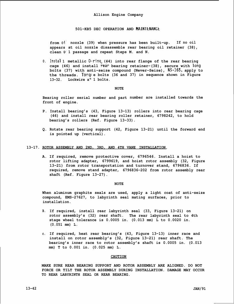
from oi”appearsclean o
Instal 10.
Allison Engine Company
501-KB5 DEC OPERATION AND MAINTENANLt
nozzle (39) when pressure has been built-up. If no oilat oil nozzle disassemble rear bearing oil retainer (38),1 passage and repeat Steps M. and N.
metallic O-rinq (44) into rear flange of the rear bearingcage (46) and install Fear bearing retainer-(38), secure with lo~gbolts (37) with anti-seize compound (Never-Seize), NS-165, apply tothe threads. Torql13-32. Lockwire a“
e bolts (36 and1 bolts.
NOTE
Bearing roller serial number and partfront of engine.
37) in sequence shown in Figure
number are installed towards the
P. Install bearing’s (43, Figure 13-13) rollers into rear bearing cage(46) and install rear bearing roller retainer, 6798242, to holdbearing’s rollers (Ref. Figure 13-33).
Q. Rotate rear bearing support (42, Figure 13-21) until the forward endis pointed up (vertical).
13-17. ROTOR ASSEMBLY AND 2ND, 3RD, AND 4TH VANE INSTALLATION.
A. If required, remove protective cover, 6796546. Install a hoist torotor lifting adapter, 6799619, and hoist rotor assembly (32, Figure13-21) from rotor transportation and turnover stand, 6796836. Ifrequired, remove stand adapter, 6796836-202 from rotor assembly rearshaft (Ref. Figure 13-27).
NOTE
When aluminum graphite seals are used, apply a light coat of anti-seizecompound, EMS-27627, to labyrinth seal mating surfaces, prior toinstallation.
B.
c.
If required, install rear labyrinth seal (33, Figure 13-21) onrotor assembly’s (32) rear shaft. The rear labyrinth seal to 4thstage wheel tolerance is 0.0005 in. (0.013 mm) L to 0.0020 in.(0.051 mm) L.
If required, heat rear bearing’s (43, Figure 13-13) inner race andinstall on rotor assembly’s (32, Figure 13-21) rear shaft. Thebearing’s inner race to rotor assembly’s shaft is 0.0005 in. (0.013mm) T to 0.001 in. (0.025 mm) L.
CAUTION
MAKE SURE REAR BEARING SUPPORT AND ROTOR ASSEMBLY ARE ALIGNED. DO NOTFORCE OR TILT THE ROTOR ASSEMBLY DURING INSTALLATION. DAMAGE MAY OCCURTO REAR LABYRINTH SEAL OR REAR BEARING.
13-42 JAN/91
—
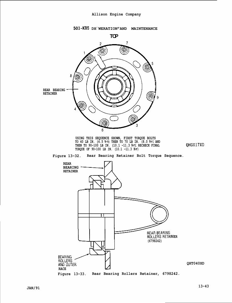
REAR BEARINGRETAINER
USING THIS SEQUENCE SHOWN, FIRST TORQUE BOLTSTO 40 LB IN. (4.5 N-m), THEN TO 70 LB IN. (8.0 N-m) ANDTHEN TO 90-100 LB IN. (10.1 -11.3 N.m). RECHECK FINALTORQUE OF 90-100 LB IN. (10.1 -11.3 Nom)
Figure 13-32. Rear Bearing Retainer Bolt Torque Sequence.
REAR
A
BEARING ~=RETAINER
II
Allison Engine Company
501-KB5 DH--WERATION”AND MAINTENANCE
TOP
QHG017XD
T(6798242)
W&J& /..tm n,l-rrnANU UUltll
RACE L4
ER
QHT040XD
Figure 13-33. Rear Bearing Rollers Retainer, 6798242.
JAN/91 13-43
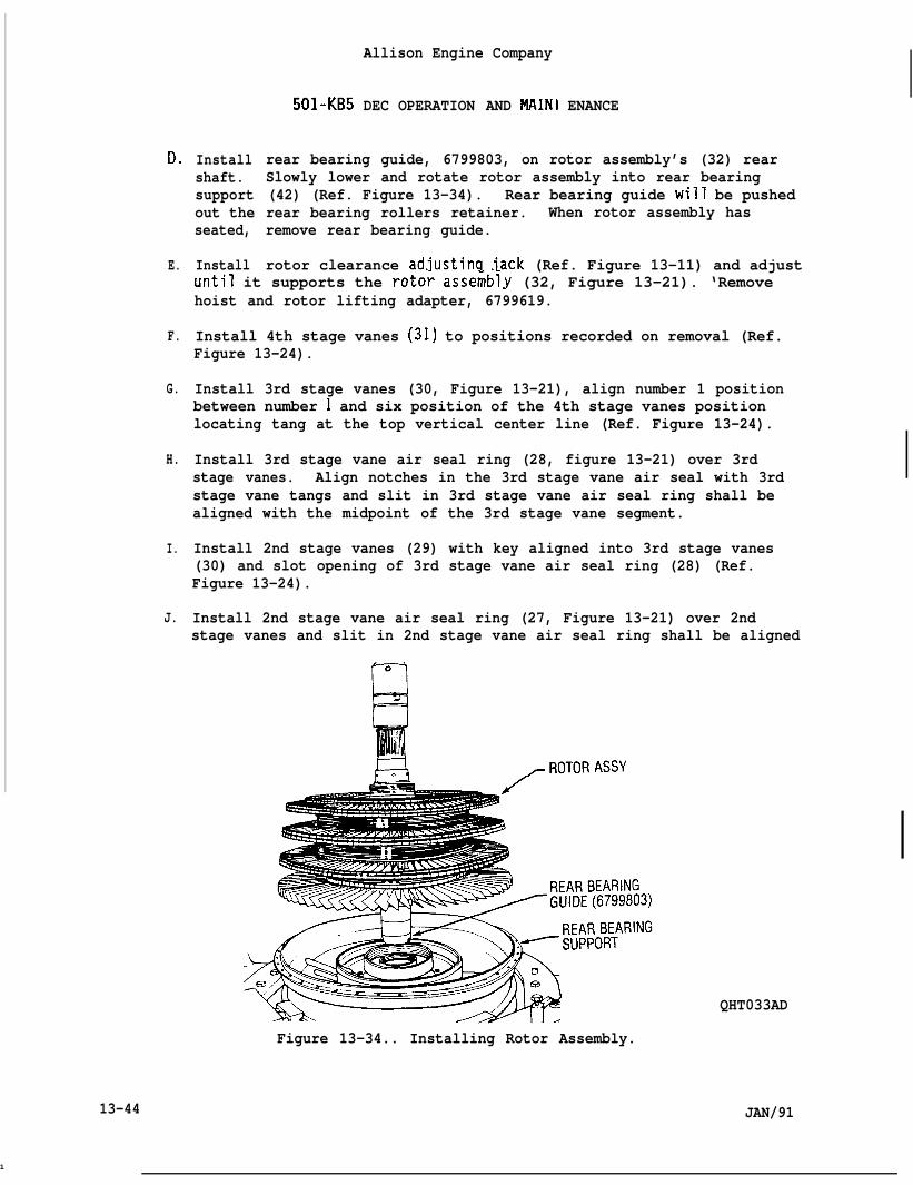
Do
E.
F.
G.
H.
I.
J.
Installshaft.supportout theseated,
Install
501-KB5
Allison Engine Company
DEC OPERATION AND MAIN1 ENANCE
rear bearing guide, 6799803, on rotor assembly’s (32) rearSlowly lower and rotate rotor assembly into rear bearing(42) (Ref. Figure 13-34). Rear bearing guide will be pushedrear bearing rollers retainer. When rotor assembly hasremove rear bearing guide.
rotor clearance ad.justincl jack (Ref. Figure 13-11) and adjustuntil it supports the roto; asse;bly (32, Figure 13-21). ‘Removehoist and rotor lifting adapter, 6799619.
Install 4th stage vanes (31) to positions recorded on removal (Ref.Figure 13-24).
Install 3rd stage vanes (30, Figure 13-21), align number 1 positionbetween number 1 and six position of the 4th stage vanes positionlocating tang at the top vertical center line (Ref. Figure 13-24).
Install 3rd stage vane air seal ring (28, figure 13-21) over 3rdstage vanes. Align notches in the 3rd stage vane air seal with 3rdstage vane tangs and slit in 3rd stage vane air seal ring shall bealigned with the midpoint of the 3rd stage vane segment.
Install 2nd stage vanes (29) with key aligned into 3rd stage vanes(30) and slot opening of 3rd stage vane air seal ring (28) (Ref.Figure 13-24).
Install 2nd stage vane air seal ring (27, Figure 13-21) over 2ndstage vanes and slit in 2nd stage vane air seal ring shall be aligned
~ROTORASSY
QHT033AD
Figure 13-34.. Installing Rotor Assembly.
13-44 JAN/91
1
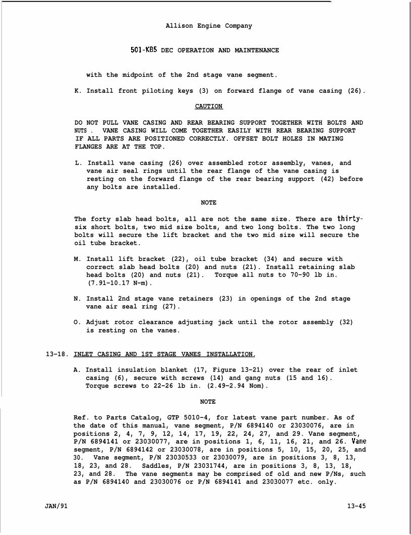
Allison Engine Company
501-KB5 DEC OPERATION AND MAINTENANCE
with the midpoint of the 2nd stage vane segment.
K. Install front piloting keys (3) on forward flange of vane casing (26).
CAUTION
DO NOT PULL VANE CASING AND REAR BEARING SUPPORT TOGETHER WITH BOLTS ANDNUTS . VANE CASING WILL COME TOGETHER EASILY WITH REAR BEARING SUPPORTIF ALL PARTS ARE POSITIONED CORRECTLY. OFFSET BOLT HOLES IN MATINGFLANGES ARE AT THE TOP.
L. Install vane casing (26) over assembled rotor assembly, vanes, andvane air seal rings until the rear flange of the vane casing isresting on the forward flange of the rear bearing support (42) beforeany bolts are installed.
NOTE
The forty slab head bolts, all are not the same size. There are thirty-six short bolts, two mid size bolts, and two long bolts. The two longbolts will secure the lift bracket and the two mid size will secure theoil tube bracket.
M. Install lift bracket (22), oil tube bracket (34) and secure withcorrect slab head bolts (20) and nuts (21). Install retaining slabhead bolts (20) and nuts (21). Torque all nuts to 70-90 lb in.(7.91-10.17 N-m).
N. Install 2nd stage vane retainers (23) in openings of the 2nd stagevane air seal ring (27).
O. Adjust rotor clearance adjusting jack until the rotor assembly (32)is resting on the vanes.
13-18. INLET CASING AND 1ST STAGE VANES INSTALLATION.
A. Install insulation blanket (17, Figure 13-21) over the rear of inletcasing (6), secure with screws (14) and gang nuts (15 and 16).Torque screws to 22-26 lb in. (2.49-2.94 Nom).
NOTE
Ref. to Parts Catalog, GTP 5010-4, for latest vane part number. As ofthe date of this manual, vane segment, P/N 6894140 or 23030076, are inpositions 2, 4, 7, 9, 12, 14, 17, 19, 22, 24, 27, and 29. Vane segment,P/N 6894141 or 23030077, are in positions 1, 6, 11, 16, 21, and 26. Vanesegment, P/N 6894142 or 23030078, are in positions 5, 10, 15, 20, 25, and30. Vane segment, P/N 23030533 or 23030079, are in positions 3, 8, 13,18, 23, and 28. Saddles, P/N 23031744, are in positions 3, 8, 13, 18,23, and 28. The vane segments may be comprised of old and new P/Ns, suchas P/N 6894140 and 23030076 or P/N 6894141 and 23030077 etc. only.
JAN/91 13-45
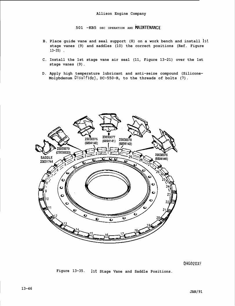
Allison Engine Company
501 -KB5 DEC OPERATION AND FIAINTENANCE
B. Place guide vane and seal support (8) on a work bench and install 1ststage vanes (9) and saddles (10) the correct positions (Ref. Figure13-35) .
C. Install the 1st stage vane air seal (11, Figure 13-21) over the 1ststage vanes (9).
D. Apply high temperature lubricant and anti-seize compound (Silicone-Molybdenum Disulfide), DC-550-R, to the threads of bolts (7).
QHG020XF
Figure 13-35. 1st Stage Vane and Saddle Positions.
13-46
I
JAN/91
Allison Engine Company
501-KB5 DEC OPERATION AND MAINTENANCE
NOTE
The gang nut which has a wider spacing of the two center nuts goes tothe top or over the dowel pin.
E. Install guide vane and seal support (8) on the rear face of the inletcasing (6), secure with gang nuts (12 and 13) and bolts (7). Torquebolts to 74-89 lb in. (8.4-10.0 N“m) and lockwire bolts.
NOTE
Make sure front piloting keys (3, Figure 13-21) are installed on therear of the front flange on the vane casing (26).
F. Install assembled inlet casing (6), with the O positioning mark onthe rear flanqe to top, to the vane casinq (26). Install Protective-..cover, 6799717, on iniet casing.
G. Apply high temperature lubricant and anti-seize compound(Silicone-Molybdenum Disul fide), DC-550-R, to the threadbolts (l).
NOTE
The eight longer slab head bolts retain the four front pile’the 3, 6, 9, and 12 o’clock or the Splitline A positions 1,25, 36, 37, and 48. The six midsize slab head bolts retainupper oil tube brackets and a lower oil tube bracket at thepositions 20, 21, 26, 27, 32, and33 (Ref. Figure 13-21).
H. Install the upper oil tube brackets (4) and the lower oi”bracket (5), secure Splitline A with the correct slab hei
of slab head
ing keys at12, 13, 24,the twoSplitline A
tubed bolts (1)
and nuts”(2). Torque” all nuts to 70-90 lb in. (7.91-10.17 N-m). ‘ ‘
13-19. FRONT BEARING SUPPORT AND FRONT BEARING CAGE INSTALLATION.
A. Install rotor front labyrinth seal (19, Fi~ure 13-21) on rotorassembly’s (32) front shaft and sec;re’front labyrinth seal to rotor assembly0.000-0.001 in. (0.000-0.025 mm) L.
NOTE
witfi locking’. The rotorfront shaft fit shall be
When aluminum graphite seals are used, apply a light coat of anti-seizecompound, EMS-27627, to labyrinth seal mating surface, prior toinstallation.
B. If required, apply clean engine oil to the mating surfaces of thesplit seal rings (31 and 32, Figure 13-13) and the front bearing cage(27). Install split seal rings on the front bearing cage.
JAN/91 13-47
Allison Engine Company
501 -KB5 DEC OPERATION AND MAINTENANCE
C. Install front bearing vibration damper (30) on the front of frontbearing cage (27) and install front bearing cage into front bearingsupport (26) aligning locating key and slot.
NOTE
Be sure the damper ring has been checked with the mating front bearingsupport and bearing cage for the 0.003 in. (0.08 mm) maximum clearance.
D. Secure the front bearing cage (27) to the front bearing support (26)with the outer retaining ring (29).
CAUTION
MAKE SURE THE NOTCHES IN THE INTERNAL RETAINING RING ARE ENGAGED WITHTHE PINS IN THE FRONT BEARING SUPPORT. WHEN PROPERLY ENGAGED, INTERNALRETAINING RING GAP WILL BE POSITIONED AT THE TOP TO ALLOW OIL NOZZLESPRAY TO FRONT BEARING.
E. Install front bearing’s (25) outer race in front bearing cage (27)and secure with internal retaining ring (28). The front bearing’souter race to front bearing cage tolerance is 0.0001 in. (0.0025 mm)T minimum and 0.0014 in. (0.036 mm) L maximum.
F. Install front bearing support (26) and front bearing cage (27) intofront of the turbine unit (34) inlet casing and retain by two bolts(8) .
13-20. FRONT LABYRINTH SEAL. BEARING, SHAFT ADAPTER, SHAFT COUPLING, ANDTURBINE COUPLING CLAMP NUT INSTALLATION.
A. Heat front labyrinth seal (33, Figure 13-13) to 250-300”F(122 °-1480C) and install on forward end of the turbine unit (34)rotor shaft, with the small ID forward. The front labyrinth seat tofront bearing cage tolerance is 0.002 in. (0.05 mm) L minimum and0.006 in. (0.15 mm) L maximum.
B. Install front bearing inner race and rollers guide, 6799634, on frontbearing support (26) (Ref. Figure 13-36).
NOTE
Make sure bearing inner race puller lip is forward on installation.
C. Heat bearing’s (25, Figure 13-13) inner race and rollers to 250-300”F(122” -148”C). Install bearing’s inner race and rollers on forwardend of turbine unit (34) rotor shaft, with the bearing’s inner race
13-48 JAN/91
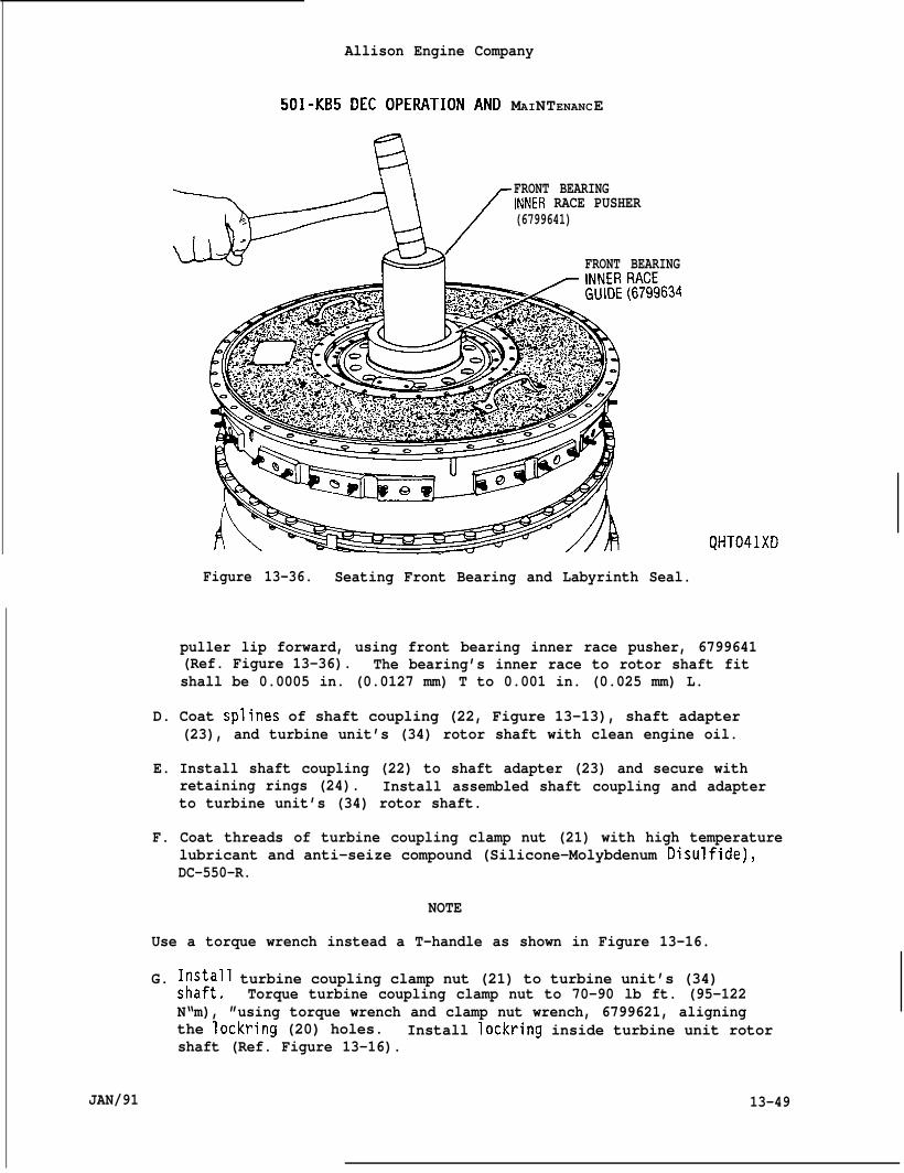
Allison Engine Company
501-KB5 DEc OpERATION AND MAINTENANCE
‘a*I FRONT BEARING
INNER RACE PUSHER/: (6799641).
FRONT BEARING
QHT041XD
Figure 13-36. Seating Front Bearing and Labyrinth Seal.
puller lip forward, using front bearing inner race pusher, 6799641(Ref. Figure 13-36). The bearing’s inner race to rotor shaft fitshall be 0.0005 in. (0.0127 mm) T to 0.001 in. (0.025 mm) L.
D. Coat splines of shaft coupling (22, Figure 13-13), shaft adapter(23), and turbine unit’s (34) rotor shaft with clean engine oil.
E. Install shaft coupling (22) to shaft adapter (23) and secure withretaining rings (24). Install assembled shaft coupling and adapterto turbine unit’s (34) rotor shaft.
F. Coat threads of turbine coupling clamp nut (21) with high temperaturelubricant and anti-seize compound (Silicone-Molybdenum Disulfide),DC-550-R.
NOTE
Use a torque wrench instead a T-handle as shown in Figure 13-16.
G. ~;:~;ll turbine coupling clamp nut (21) to turbine unit’s (34)Torque turbine coupling clamp nut to 70-90 lb ft. (95-122
N“m), ”using torque wrench and clamp nut wrench, 6799621, aligningthe lockring (20) holes. Install lockring inside turbine unit rotorshaft (Ref. Figure 13-16).
JAN/91 13-49
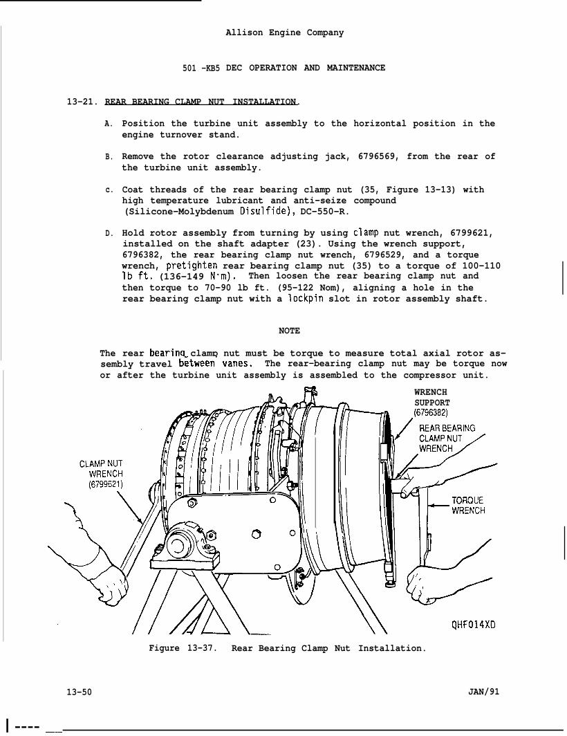
501 -KB5
Allison Engine Company
DEC OPERATION AND MAINTENANCE
13-21. REAR BEARING CLAMP NUT INSTALLATION.
A.
B.
c.
D.
The
Position the turbine unit assembly to the horizontal position in theengine turnover stand.
Remove the rotor clearance adjusting jack, 6796569, from the rear ofthe turbine unit assembly.
Coat threads of the rear bearing clamp nut (35, Figure 13-13) withhigh temperature lubricant and anti-seize compound(Silicone-Molybdenum Disulfide), DC-550-R.
Hold rotor assembly from turning by using clamp nut wrench, 6799621,installed on the shaft adapter (23). Using the wrench support,6796382, the rear bearing clamp nut wrench, 6796529, and a torquewrench, pretighten rear bearing clamp nut (35) to a torque of 100-110lbft. (136-149 N”m). Then loosen the rear bearing clamp nut andthen torque to 70-90 lb ft. (95-122 Nom), aligning a hole in therear bearing clamp nut with a lockpin slot in rotor assembly shaft.
NOTE
rear bearinq clamp nut must be torque to measure total axial rotor as-sembly travel b~tween- vanes. The rear-bearing clamp nut may be torque nowor after the turbine unit assembly is assembled to the compressor unit.
WRENCHm SUPPORT
Figure 13-37. Rear Bearing Clamp Nut Installation.
13-50 JAN/91I
I ---- –.-
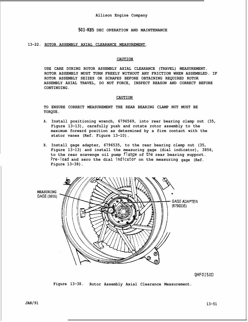
13-22.
Allison Engine Company
501-KB5 DEC OPERATION AND MAINTENANCE
ROTOR ASSEMBLY AXIAL CLEARANCE MEASUREMENT.
CAUTION
USE CARE DURING ROTOR ASSEMBLY AXIAL CLEARANCE (TRAVEL) MEASUREMENT.ROTOR ASSEMBLY MUST TURN FREELY WITHOUT ANY FRICTION WHEN ASSEMBLED. IFROTOR ASSEMBLY SEIZES OR SCRAPES BEFORE OBTAINING REQUIRED ROTORASSEMBLY AXIAL TRAVEL, DO NOT FORCE, INSPECT REASON AND CORRECT BEFORECONTINUING.
CAUTION
TO ENSURE CORRECT MEASUREMENT THE REAR BEARING CLAMP NUT MUST BETORQUE.
A.
B.
Install positioning wrench, 6796569, into rear bearing clamp nut (35,Figure 13-13), carefully push and rotate rotor assembly to themaximum forward position as determined by a firm contact with thestator vanes (Ref. Figure 13-10).
Install gage adapter, 6796535, to the rear bearing clamp nut (35,Figure 13-13) and install the measuring gage (dial indicator), 3856,to the rear scavenge oil pump flanqe of th; rear bearing support.Pre-load and zero the dial indicat~r on the measuringFigure 13-38).
gage (Ref.
MEASURINGGAGE(3856)
QHF015XD
Figure 13-38. Rotor Assembly Axial Clearance Measurement.
JAN/91 13-51
13-23.
13-52
c.
D.
Allison Engine Company
501-KB5 DEC OPERATION AND MAINTENANCE
If required, install positioning wrench, 6796569, and then move therotor assembly to the maximum rearward position measuring themovement from the maximum forward position. This movement must notbe less than 0.328 inch (8.33 mm). If total rotor assembly axialclearance (travel) is less than 0.328 inch (8.33 mm), inspect turbineunit assembly for misaligned or warped vanes and/or incorrectassembled parts, correct as required.
Do not remove positioning wrench, 6796569, gage adapter, 6796535, and. - . .measuring gage 3856, from rear of turbine unit assembly. Move rotorassembly to the maximum rear position.
COMBUSTION INNER CASING, COMBUSTION INNER CASING LINER. SCAVENGE OILTUBE, AND TUBE AND NOZZLE ASSEMBLY INSTALLATION.
CAUTION
DO NOT ALLOW ROTOR ASSEMBLY TO DROP WHILE POSITION IS BEING CHANGED.
A.
B.
c.
D.
E.
F.
G.
Slowly turn turbine unit assembly to vertical position (front end up)in engine turnover stand.
If required, assemble tube and nozzle assembly (15, Figure 13-13) asfollows:
1. Install a tab lockwasher (18) and taper oil nozzle (19), andtorque to 70-85 lb in. (8.0-9.6 N“m). Bend a tab to lock taperoil nozzle in place.
2. Install a tab lockwasher (16) and oil nozzle (17) and torque to70-85 lb in. (8.0-9.6 Nom). Bend a tab to lock oil nozzle inplace.
Install tube and nozzle assembly (15) and secure with bolts (14).Torque bolts to 70-85 lb in. (8.0-9.6 N“m) and lockwire bolts.
Install scavenge oil tube (13) and secure with bolts (12). Torquebolts to 70-85 lb in. (8.0-9.6 N“m) and lockwire bolts.
Remove the two bolts (8) installed temporarily in Paragraph 13-19,Step F.
Coat the threads of bolts (8) with high temperature lubricant andanti-seize compound (Silicone-Molybdenum Disulfide), DC-550-R.
Install metallic type seal (10) to the rear of combustion innercasing liner (11) and the metallic type O-ring (9) to the front ofthe combustion inner casing liner.
JAN/91
H.
I.
J.
Allison Engine Company
501-KB5 DEC OPERATION AND MAINTENANCE
Carefully install the combustion inner casing liner (11) over theinstalled scavenge oil tube (13) and tube and nozzle assembly (15),secure with coated bolts (8). Torque bolts in a circumferentialdirection to 70-85 lb in. (8.0-9.6 N-m) and lockwire bolts.
Coat the threads of bolts (2 and 3) and screws (1) with hightemperature lubricant and anti-seize compound (Silicone-MolybdenumDisulfide), DC-550-R.
Install metallic type O-ring (7) to rear flange of the combustioninner casing (6). ‘“
CAUTION
TORQUE THE RING OF BOLTS IN PROGRESSIVE STAGES OF TORQUE, 20, 40, AND 60LB IN. (2.26, 4.52, 6.78 N”M), TO PREVENT PIE CRUSTING OF THE METALLICTYPE O-RING.
K. Carefully install combustion inner casing (6) over combustion innercasing liner (11), scavenge oil tube (13), and tube and nozzleassembly (15), secure with coated bolts (3). Torque bolts in acircumferential direction in progressive stages until the finaltorque is 70-85 lb in. (8.0-9.6 N-m) and lockwire bolts.
L. Install bolts (1) at front to secure combustion inner casing (6) tocombustion inner casing liner (11). Torque bolts to 70-85 lb in.(8.0-9.6 N-m) and lockwire bolts.
M. Install screws (2) to secure to scavenge oil tube (13) and tube andnozzle assembly (15). Do not tighten screws (2). Screws will besecure on final assembly after being aligned with an alignmentfixture.
13-24. COMBUSTION LINERS INSTALLATION.
A. If required, assemble combustion liner (11, Figure 13-7) byconnecting front liner assembly (19) to the transition assembly (18)and securing with nuts (17) and bolts (16). Torque nuts to 74-89 lbin. (8.4 -10.0 Nom).
NOTE
At their record positions, all combustion liners should be installedonto the turbine unit assembly’s inlet casing and the combustion innercasing with the crossover ferrule’s clamps, spacers, bolts, and nutsinstalled.
B. Install each combustion liner (11) to forward end of combustion innercasing (6, Figure 13-13) and into the turbine unit assembly’s (22,Figure 13-7) to their position recorded and marked on disassembly.Install three gaskets (9) and port plugs (10) to retain each com-
JAN/91 13-53
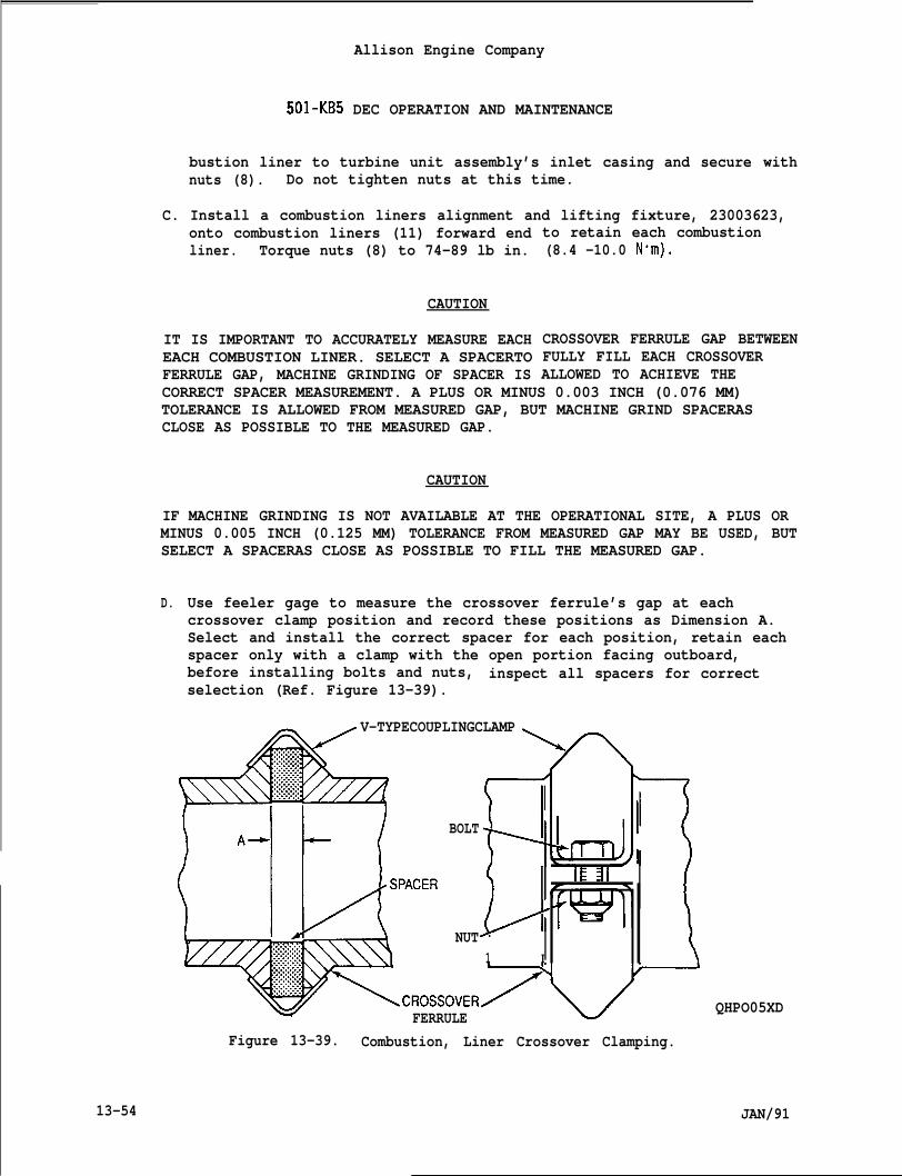
Allison Engine Company
501-KB5 DEC OPERATION AND MAINTENANCE
bustion liner to turbine unit assembly’s inlet casing and secure withnuts (8). Do not tighten nuts at this time.
C. Install a combustion liners alignment and lifting fixture, 23003623,onto combustion liners (11) forward endliner. Torque nuts (8) to 74-89 lb in.
CAUTION
IT IS IMPORTANT TO ACCURATELY MEASURE EACHEACH COMBUSTION LINER. SELECT A SPACERTOFERRULE GAP, MACHINE GRINDING OF SPACER IS
to retain each combustion(8.4 -10.0 N“m).
CROSSOVER FERRULE GAP BETWEENFULLY FILL EACH CROSSOVERALLOWED TO ACHIEVE THE
CORRECT SPACER MEASUREMENT. A PLUS OR MINUS 0.003 INCH (0.076 MM)TOLERANCE IS ALLOWED FROM MEASURED GAP, BUT MACHINE GRIND SPACERASCLOSE AS POSSIBLE TO THE MEASURED GAP.
CAUTION
IF MACHINE GRINDING IS NOT AVAILABLE AT THE OPERATIONAL SITE, A PLUS ORMINUS 0.005 INCH (0.125 MM) TOLERANCE FROM MEASURED GAP MAY BE USED, BUTSELECT A SPACERAS CLOSE AS POSSIBLE TO FILL THE MEASURED GAP.
D. Use feeler gage to measure the crossover ferrule’s gap at eachcrossover clamp position and record these positions as Dimension A.Select and install the correct spacer for each position, retain eachspacer only with a clamp with the open portion facing outboard,before installing bolts and nuts, inspect all spacers for correctselection (Ref. Figure 13-39).
V-TYPECOUPLINGCLAMP\
BOLT
IE al
t
I
NUTL
1
FERRULEFigure 13-39. Combustion, Liner Crossover Clamping.
QHPO05XD
13-54 JAN/91
Allison Engine Company
501 -KB5 DEC OPERATION AND MAINTENANCE
CAUTION
THE CURRENT CLAMPING BOLT, MS9557-18 OR MS9697-18, IS THE ACCEPTABLEBOLT FOR USE WITH SPACERS, 23008797 DASH 4 THRU DASH 15, DIMENSION “A”WAS 0.040 TO0.150 IN. (1.02 T03.81 MM). THE CLAMPING BOLT, MS9557-220RMS9697-22, IS THE ACCEPTABLE BOLT FOR USE WITH SPACERS, 23008797 DASH16 THRU DASH 23, DIMENSION “A” WAS 0.160 TO0.230 IN. (4.07 T04.31MM) . THE LONGER BOLT IS REQUIRED TO PREVENT THE CLAMP TANGS FROM BEINGBENT AND WEARING THROUGH THE BOLT SHANK.
NOTE
It is recommended that new nuts be installed to prevent loss of nutretention.
E.
F.
Install the correct bolts (13, Figure 13-7), with the boltheadstowards the engine inlet (forward), and new nuts (14). Torque thenuts to 25-35 lb in. (2.82-3.95 N-m) above the prevailing locknuttorque (the locknut drag torque).
Remove combustion liners alignment and lifting fixture, 23003623.
13-25. TURBINE UNIT ASSEMBLY INSTALLATION.
A. Inspect alignment of the scavenge oil tube (13, Figure 13-13) andtube and nozzle assembly (15) using alignment fixture, 6799708 (Ref.Figure 13-39).
B. Install split seal rings (20, Figure 13-7) on turbine unit assembly’s(22) combustion inner casing.
C. Install O-rings (21) on turbine unit assembly’s (22) oil tubes, oneon the tube and nozzle assembly and two on the scavenge oil tube.
D. If required, install turbine coupling shaft assembly (5) tocompressor diffuser and secure with retaining ring (7).
E. Install lifting adapter, 6799620, to top of turbine unit assembly(22) (Ref. Figure 13-8).
F. If required, install compressor holder, 3755, on front of compressor(Ref. Figure 13-2).
G. If required, rotate the turbine unit assembly (22, Figure 13-7) to ahorizontal position in the engine turnover stand, 6797352, and standadapter, 6796644, using the lifting adapter and hoist (Ref. Figure13-9).
JAN/91 13-55
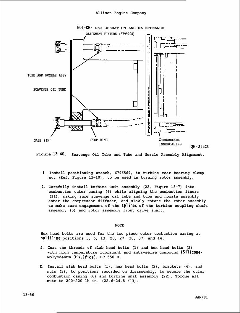
DTUBE AND NOZZLE ASSY
SCAVENGE OIL TUBE
Allison Engine Company
501-KB5 DEC OPERATION AND MAINTENANCEALIGNMENT FIXTURE (6799708)
--~--—..~--— -
-.— --/
1 -. —-- /
GAGE PIN’ STOP RING COmbUStiOnINNERCASING QHF016XD
Figure 13-40. Scavenge Oil Tube and Tube and Nozzle Assembly Alignment.
H,
1.
Install positioning wrench, 6796569, in turbine rear bearing clampnut (Ref. Figure 13-10), to be used in turning rotor assembly.
Carefully install turbine unit assembly (22, Figure 13-7) intocombustion outer casing (6) while aligning the combustion liners(11), making sure scavenge oil tube and tube and nozzle assemblyenter the compressor diffuser, and slowly rotate the rotor assemblyto make sure engagement of the splines of the turbine coupling shaftassembly (5) and rotor assembly front drive shaft.
NOTE
Hex head bolts are used for the two piece outer combustion casing atsplitline positions 3, 6, 13, 20, 27, 30, 37, and 44.
J.
K.
13-56
Coat the threads of slab head bolts (1) and hex head bolts (2)with high temperature lubricant and anti-seize compound (Silicone-Molybdenum Disulfide), DC-550-R.
Install slab head bolts (l), hex head bolts (2), brackets (4), andnuts (3), to positions recorded on disassembly, to secure the outercombustion casing (6) and turbine unit assembly (22). Torque allnuts to 200-220 lb in. (22.6-24.8 N“m).
JAN/91
I 1
Allison Engine Company
501-KB5 DEC OPERATION AND MAINTENANCE
NOTE
If the rear bearing clamp nut has not been torqued, do the followingstep.
L. Ifas
1.
2.
3.
4.
required, torque the rear bearing c“follows:
Remove positioning wrench, 6796569,(35) .
amping nut (35, Figure 13-13)
from rear bearing clamp nut
Using the wrench support, 6796382, rear bearing clamp nut wrench,6796529,and a torque wrench, torque the rear bearing clamp nut(35) to a torque of 100-110 lb ft. (136-149 N-m), then loosenrear bearing clamp nut and apply a torque of 70-90 lb ft. (95-122N“m), aligning a hole in the rear bearing clamp nut with alockpin slot in rotor assembly shaft (Ref. Figure 13-6).
Remove wrench support, 6796382, rear bearing clamp nut wrench,6796529, torque wrench and from the front compressor removecompressor holder, 3755.
Install Dositioninu wrench. 6796569. to the rear bearina clamD nut(35, Figure 13-13)”(Ref. Figure 13-10) and position the-rotor’assembly to full forward position.
CAUTION
USE CARE DURING ROTOR ASSEMBLY AXIAL CLEARANCE (TRAVEL) MEASUREMENT.ROTOR ASSEMBLY MUST TURN FREELY WITHOUT ANY FRICTION. IF ROTOR ASSEMBLYSEIZES OR SCRAPES BEFORE OBTAINING ROTOR ASSEMBLY AXIAL TRAVEL, DO NOTFORCE, INSPECT FOR REASON AND CORRECT BEFORE CONTINUING.
CAUTION
IF TOTAL AXIAL TRAVEL OF THE ROTOR ASSEMBLY IS LESS THAN 0.328 INCH(8.34 mm) , INSPECT TURBINE UNIT ASSEMBLY FOR MISALIGNED OR WARPED VANESAND/OR INCORRECT ASSEMBLED PARTS, CORRECT AS REQUIRED.
5. Install gage adapter, 6796535, to the rear clamp nut (35, Figure13-13) and install measuring gage (dial indicator), 3856, to therear scavenge oil pump flange of the rear bearing support.Positioning the measuring gage pickup so that it contacts gageadapter. Pre-load and zero the dial on the measuring gage dialindicator (Ref. Figure 13-38). Carefully pull and rotate rotorassembly to full rearward position. Total axial travel must be0.328 inch (0.834 mm) or more.
JAN/91 13-57
Allison Engine Company
501 -KB5 DEC OPERATION AND MAINTENANCE
6. Install compressor holder, 3755, to forward end of compressor unit(Ref. Figure 13-2).
M. Move the rotor assembly full maximum forward position of the totalaxial travel, using the positioning wrench, 6796569, and install gageadapter, 6796535, to the rear bearing clamp nut (35, Figure 13-13)and install the measuring gage (dial indicator), 3856, to the rearscavenge oil pump flange. Pre-load and zero the measuring gage dialindicator (Ref. Figure 13-38). Take a reference measurement from abar (straightedge) across the rear scavenge oil pump flange to rearface of rear bearing clamp nut. Record this measurement as DimensionA. Record position of bar before removing bar.
CAUTION
IF TOTAL AXIAL TRAVEL CANNOT BE MET, 0.328 INCH (8.34 mm) OR MORE,INSPECT TURBINE UNIT ASSEMBLY FOR REASON WHY. THE TOTAL AXIAL TRAVELMUST BE OBTAINED OR DAMAGE MAY OCCUR.
N. Move the rotor assembly to the full maximum rearward position andrecord this measurement as the total rotor assembly axial travel.This movement must be at least 0.328 inch (8.34 mm) or more. Recordthis measurement as total axial travel.
O. Remove positioning wrench, 6796569, with the rotor assembly in thefull rearward position.
P. Install O-ring (8, Figure 13-3) on forward end of tie bolt (6), coatthe tie bolt threads with lubricant, MIL-M-7866, and install tie boltinto turbine unit assembly and the compressor unit, making sure themeasuring gage reading is the same as taken in Step M. before the tiebolt touches the rear bearing retaining nut.
CAUTION
THE CORRECT MEASURING GAGE INITIAL READING FORATWO PIECE OUTERCOMBUSTION CASING IS 0.253 INCH (6.42 MM) FOR REAROF VANE CLEARANCE.
CAUTION
THE MEASURING GAGE FINAL READING ON A TWO PIECE OUTER COMBUSTION CASINGMUST NOT BE LESS THAN 0.247 INCH (6.28 MM). FINAL REAR VANE CLEARANCEMUST BE 0.247 TO0.253 INCH (6.28 T06.42 MM).
Q. Install wrench support, 6796382, and tie bolt wrench, 6796533, tight-en tie bolt (6, Figure 13-3) on one piece outer combustion casinguntil an initial reading of 0.214 in. (5.43 mm) is obtained on the
13-58 JAN/91
Allison Engine Company
501 -KB5 DEC OPERATION AND MAINTENANCE
JAN/91
measuring gage. Remove wrench support and tie bolt wrench inspectfor alignment of tie bolt Iockpin slot to lockpin slot in the rearbearing clamp nut and rotor assembly shaft. If lockpin slot is notaligned screw tie bolt in (tightening) to align lockpin slot. In-stall lockpin (3) and inspect reading on measuring gage, the readingmust not be less than 0.209 in. (5.31 mm) and the final rear vaneclearance must be 0.209 to 0.214 in. (5.31 to 5.43 mm). If not,repeat Step M., N.j O., P., and Q.
-
R. Remove measuring gage and gage adapter from rear bearand rear bearing support.
S. Install gasket (5, Figure 13-2) to the drive couplingassembled drive coupling into rear splines of the tie
ng clamp nut
(4) and installbolt (6). Make
sure lockpin (3) is installed and aligned in all lockpin slots.
T. Coat threads of the tie bolt retaining nut (2) with lubricant,MIL-L-25681, and install tie bolt retaining nut inside of rearbearing clamp nut, using wrench support, 6796382, retaining nutwrench, 6796530, and a torque wrench (Ref. Figure 13-4). Torque tiebolt retaining nut to 140-150 lb ft. (190-203 Nom), then loose tiebolt retaining nut and then torque 125 lb ft. (169 N“m). Inspectfor lockring (1, Figure 13-3) hole alignment between tie boltretaining nut and rear bearing clamp nut, if not aligned, tighten tiebolt retaining nut to next aligning hole. Remove wrench support,retaining nut wrench, and torque wrench.
U. Inspect final rotor assembly position (rear of vane clearance) asfollows:
CAUTION
MAKE SURE BOTH DIMENSION A AND B MEASUREMENT ARE TAKEN AT THIS SAMERECORDED POSITION, TO ENSURE CORRECT MEASUREMENT.
NOTE
The turbine rotor assembly movement at this time consists of thecompressor rear bearing internal clearance (axial) and axial movement ofthe compressor rear bearing outer race inmovement must not exceed 0.024 inch (0.61the compressor unit should be replaced.
1. Due to the bearing movement, obtain
the bearing cage. Thismm) . If movement is excessive
both the extreme forward andrearward positions measurement of the rotor assembly. Take thesemeasurements as outlined in Step M. by placing a bar (straight-edge) in the same recorded position when taking these two measure-ments from the bar to rear face of rear bearing clamp nut. Takethe average of the two measurements and record as Dimension B.
13-59
Allison Engine Company
501-KB5 DEC OPERATION AND MAINTENANCE
v.
w.
x.
Y.
z.
AA.
2.
3.
4.
5.
6.
Subtract Dimension B from the record Dimension A and thisdimension (rear of vane clearance) should be, for the one pieceouter combustion between 0.209 to 0.214 inch (5.31 to 5.43 mm) andfor the two piece outer combustion casing between 0.247 to 0.253inch (6.28 to 6.42 mm).
If rear of vane clearance is within its limits, remove tie boltretaining nut (2, Figure 13-2), lockpin (3), drive coupling (4)and gasket (5).
If clearance is more than allowed limit, turn tie bolt (6)clockwise (in), for every tie bolt slot change the dimension withdecrease by 0.006 inch (0.15 mm).
If clearance is less than allowed limit, turn tie bolt (6)counterclockwise (out), for every tie bolt slot change thedimension with increase by 0.006 inch (0.15 mm).
Repeat Step S., T., and U.
Install lockring (1, Figure 13-3) and remove compressor holder, 3755,from front of compressor.
Install rear bearing scavenge oil pump and external scavenge oilpump’s oil lines as outlined in Section 7, Engine Lubrication System.
Install nuts, bolts, brackets, and T/C harness.
Install T/C’s and T/C junction block as outlined in Section 5,Turbine Outlet Temperature (TOT) System.
Install liner supports and igniter as outlined in Section 12,Combustion Section and Ignition System.
Install all external lines, hoses, and ignition leads that wereremoved.
13-26. ENGINE INSTALLATION.
A. Install engine as outlined in Section 1, Engine Description.
B. Perform an operation and leakage test.
13-60 JAN/91
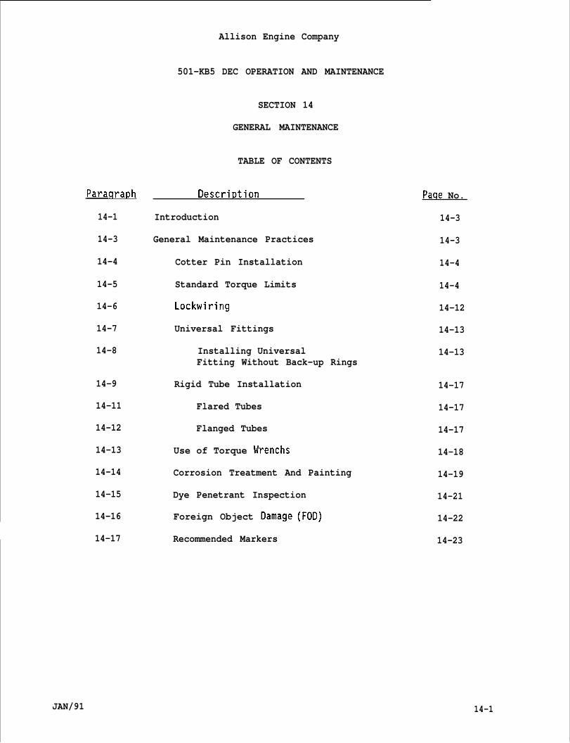
ParaqraDh
14-1
14-3
14-4
14-5
14-6
14-7
14-8
14-9
14-11
14-12
14-13
14-14
14-15
14-16
14-17
Allison Engine Company
501-KB5 DEC OPERATION AND MAINTENANCE
SECTION 14
GENERAL MAINTENANCE
TABLE OF CONTENTS
Descri~tion
Introduction
General Maintenance Practices
Cotter Pin Installation
Standard Torque Limits
Lockwiring
Universal Fittings
Installing UniversalFitting Without Back-up Rings
Rigid Tube Installation
Flared Tubes
Flanged Tubes
Use of Torque Wrenchs
Corrosion Treatment And Painting
Dye Penetrant Inspection
Foreign Object Oamage (FOD)
Recommended Markers
Paqe No.
14-3
14-3
14-4
14-4
14-12
14-13
14-13
14-17
14-17
14-17
14-18
14-19
14-21
14-22
14-23
JAN/91 14-1
Allison Engine Company
_____ ——— .—. _..501 -KB5 DEC OPERATION AND MAINTENANCE
INDEX TO FIGURES
Fiaure No. Title
14-1
14-2
14-3
14-4
14-5
Fiaure No.
14-1
14-2
14-3
14-4
14-5
14-6
14-7
14-8
14-9
14-10
14-2
Cotter Pin Installation
Step-by-Step Example of Lockwiring
Examples of Lockwiring
Universal Fittings
Torque Wrench and Extension
INDEX TO TABLES
Standard Torque Limits to Either the Nutor Bolt, When a Steel Tension Type Nutis Used in the Combination. Valuesalso Apply to Bolts Torqued intoSteel Tapped Hobs or Steel Inserts.
Standard Torque Limits to be Applied toEither Nut or Bolt When a Steel ShearType is Used in the Combination.
Standard Torque Limits for BoltsTorqued into Aluminum Tapped HolesWith or Without Inserts.
Standard Torque Limits for Screwsinto Aluminum Tapped Holes Withor Without Inserts.
Standard Torque Limits for Screws Torquedinto Tension or Shear Type Nuts With orWithout Self-locking Feature. Value alsoApplies to Screws Torqued into SteelTapped Holes With or Without Inserts.
Steel Coupling Nuts on Steel Fitting
Steel With Aluminum or Aluminum WithAluminum Coupling Nuts on Fitting
Aluminum or Steel Unions
Plugs and Bleeders
Recommended Markers
Paqe No.
14-5
14-14
14-15
14-16
14-19
Paqe No.
14-6
14-7
14-8
14-8
14-9
14-10
14-10
14-11
14-11
14-23
JAN/91
Allison Engine Company
501-KB5 DEC OPERATION AND MAINTENANCE
14-1.
14-2.
14-3.
I
SECTION 14
GENERAL MAINTENANCE
INTRODUCTION.
This Section presents general maintenance information and procedures.
GENERAL MAINTENANCE PRACTICES .
CAUTION
DO NOT REUSE LOCKWIRE, COTTER PINS, PACKINGS (O-RINGS), LIP SEALS,COMPOSITION GASKETS, AND SPLIT OR TAB LOCKWASHERS. REPLACE SELF-LOCKINGNUTS WHEN THE MINIMUM BREAKAWAY TORQUE IS BELOW THE REQUIREMENTS OFSPECIFICATION MIL-N-25027. MINIMUM TORQUE IS DEFINED AS THE TORQUEREQUIRED TO START TURNING AN UNLOADED NUTONA BOLT.
NOTE
During the various stages of dismantling, observe all parts, closely forsigns of scoring, burning or other defe~ts. Frequently the-conditi& ofparts is better revealed by examination before cleaning.
A.
B.
c.
DO
Note the location and approximate position of each fuel, oil, air,and drain line fitting before transferring it from a removedaccessory to the replacement unit. This practice will facilitateinstallation and enable the connecting of various lines in theircorrect relationship. When hoses are installed, watch for evidenceof a hose being twisted, and guard against the possibility of chafingagainst other hoses or equipment.
Most maintenance work can be done with standard hand tools that anengine mechanic normally has available to him. If special tools arerequired they are specified in the maintenance practices of the itembeing worked on.
Whenever a fluid carrying part is removed, make a leakage check afterinstallation by motoring or operating the engine.
CAUTION
NOT USE COMMON LEAD PENCILS FOR MARKINGTHAT CAN EAT INTO METAL PARTS. ‘-
.
BECAUSE THEY CONTAIN GRAPHITE
I JAN/91
D.
E.
F.
G.
Allison Engine Company
501-KB5 DEC OPERATION AND MAINTENANCE
If information must be marked on a part, use only approved markingpencils (Ref. Paragraph 14-17).
Before assembly, clean all parts in the correct cleaner. Dry andlubricate, if this is required, with oil and corrosion resistantmixture.
Extreme care should be taken to prevent dirt, dust, cotter pins,nuts, washers, and other small particles from falling into the engineassembly during the maintenance. These can work into the gears oroil lines, and cause considerable damage.
Completely finish each step in the process of assemble as the workprogresses. Do not leave a bolt loose or nut uncottered pin (safety)with the idea of coming back to it later, except as specificallyinstructed herein.
14-4. COTTER PIN INSTALLATION.
A. All cotter pins used must be new,
B. The plane of cotter pin eye must be parallel to the axis of bolt orstud ,
C. The cotter pin eye must be seated against bolt or stud and prongsmust be bent tight so that cotter pin will not move axially afterinstallation.
D. If there is interference between cotter pin eye and bottom of nutcastellation, the cotter pin must be deformed slightly by forcing itinto nut castellation.
E. Figure 14-l,example (A) shows the preferred method of installation.Installation per examples (B), (C), and (D) may be done when requiredby a particular application.
14-5. STANDARD TORQUE LIMITS.
A. Standard torque limits for bolts, nuts, and screws are contained inTables 14-1, 14-2, 14-3, 14-4, and 14-5.
B. Standard torque limits for hose and tube assemblies are contained inTables 14-6 and 14-7.
1. Coupling nuts and connecting items (union, elbow, nipples, etc.)should be lubricated with clean engine oil or equivalent unlessotherwise specified, prior to torque application.
14-4 JAN/91
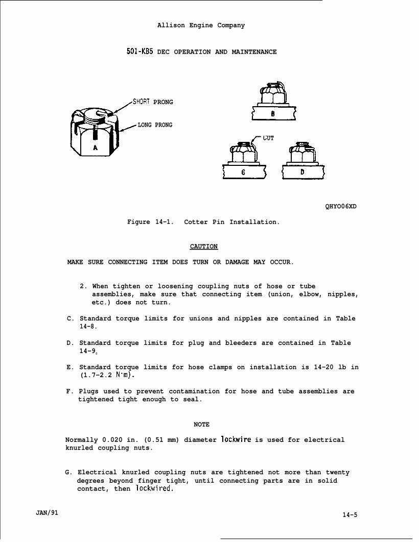
Allison Engine Company
501-KB5 DEC OPERATION AND MAINTENANCE
/SHORT PRONG
@
LONG PRONG
A ’
2!!3B
CUT
f!!!!c 2!33D
QHYO06XD
Figure 14-1. Cotter Pin Installation.
CAUTION
MAKE SURE CONNECTING ITEM DOES TURN OR DAMAGE MAY OCCUR.
2. When tighten or loosening coupling nuts of hose or tubeassemblies, make sure that connecting item (union, elbow, nipples,etc.) does not turn.
C. Standard torque limits for unions and nipples are contained in Table14-8.
D. Standard torque limits for plug and bleeders are contained in Table14-90
E. Standard torque limits for hose clamps on installation is 14-20 lb in(1.7-2.2 N“m).
F. Plugs used to prevent contamination for hose and tube assemblies aretightened tight enough to seal.
NOTE
Normally 0.020 in. (0.51 mm) diameter lockwire is used for electricalknurled coupling nuts.
G. Electrical knurled coupling nuts are tightened not more than twentydegrees beyond finger tight, until connecting parts are in solidcontact, then lockwired.
JAN/91 14-5
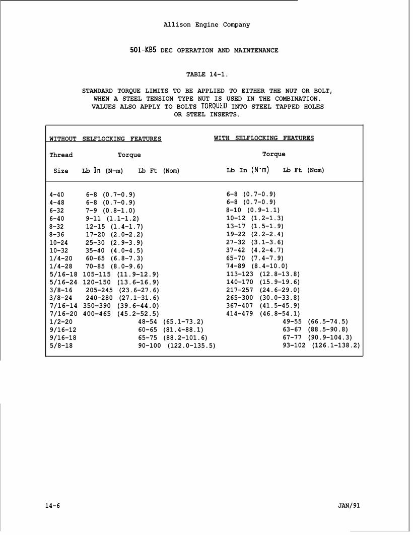
Allison Engine Company
501-KB5 DEC OPERATION AND MAINTENANCE
TABLE 14-1.
STANDARD TORQUE LIMITS TO BE APPLIED TO EITHER THE NUT OR BOLT,WHEN A STEEL TENSION TYPE NUT IS USED IN THE COMBINATION.VALUES ALSO APPLY TO BOLTS TORQUED INTO STEEL TAPPED HOLES
OR STEEL INSERTS.
WITHOUT SELFLOCKING FEATURES WITH SELFLOCKING FEATURES
Thread Torque Torque
Size Lb ln (N-m) Lb Ft (Nom) Lb In (N”m) Lb Ft (Nom)
4-40 6-8 (0.7-0.9) 6-8 (0.7-0.9)4-48 6-8 (0.7-0.9) 6-8 (0.7-0.9)6-32 7-9 (0.8-1.0) 8-10 (0.9-1.1)6-40 9-11 (1.1-1.2) 10-12 (1.2-1.3)8-32 12-15 (1.4-1.7) 13-17 (1.5-1.9)8-36 17-20 (2.0-2.2) 19-22 (2.2-2.4)10-24 25-30 (2.9-3.9) 27-32 (3.1-3.6)10-32 35-40 (4.0-4.5) 37-42 (4.2-4.7)1/4-20 60-65 (6.8-7.3) 65-70 (7.4-7.9)1/4-28 70-85 (8.0-9.6) 74-89 (8.4-10.0)5/16-18 105-115 (11.9-12.9) 113-123 (12.8-13.8)5/16-24 120-150 (13.6-16.9) 140-170 (15.9-19.6)3/8-16 205-245 (23.6-27.6) 217-257 (24.6-29.0)3/8-24 240-280 (27.1-31.6) 265-300 (30.0-33.8)7/16-14 350-390 (39.6-44.0) 367-407 (41.5-45.9)7/16-20 400-465 (45.2-52.5) 414-479 (46.8-54.1)1/2-20 48-54 (65.1-73.2) 49-55 (66.5-74.5)9/16-12 60-65 (81.4-88.1) 63-67 (88.5-90.8)9/16-18 65-75 (88.2-101.6) 67-77 (90.9-104.3)5/8-18 90-100 (122.0-135.5) 93-102 (126.1-138.2)
14-6 JAN/91
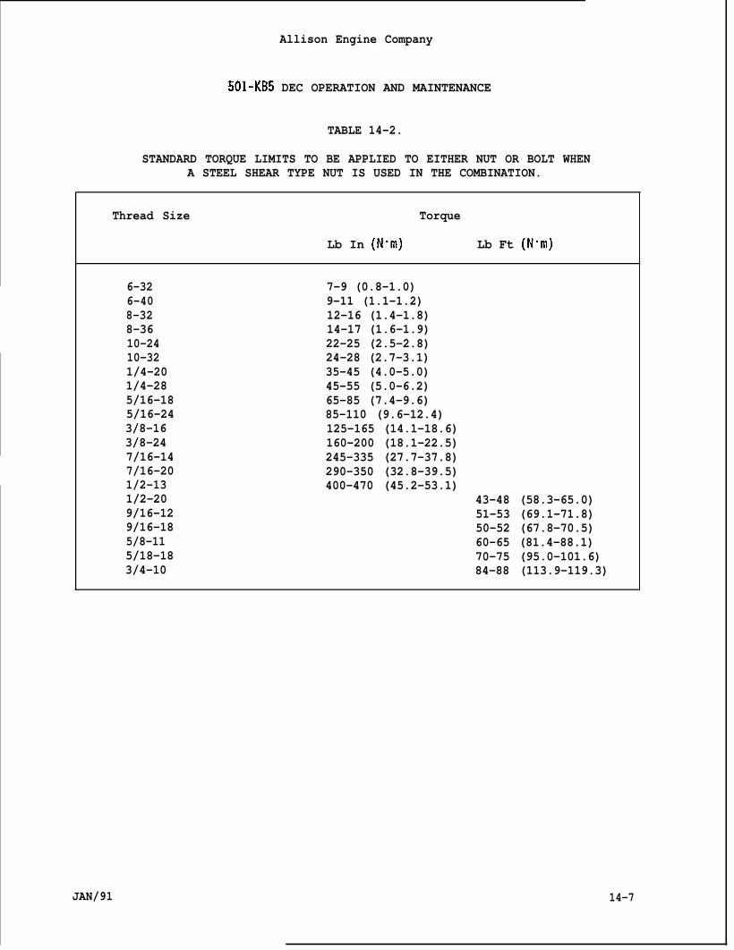
Allison Engine Company
501-KB5 DEC OPERATION AND MAINTENANCE
TABLE 14-2.
STANDARD TORQUE LIMITS TO BE APPLIED TO EITHER NUT OR BOLT WHENA STEEL SHEAR TYPE NUT IS USED IN THE COMBINATION.
Thread Size Torque
Lb In (N”m) Lb Ft (Nom)
6-32 7-9 (0.8-1.0)6-40 9-11 (1.1-1.2)8-32 12-16 (1.4-1.8)8-36 14-17 (1.6-1.9)10-24 22-25 (2.5-2.8)10-32 24-28 (2.7-3.1)1/4-20 35-45 (4.0-5.0)1/4-28 45-55 (5.0-6.2)5/16-18 65-85 (7.4-9.6)5/16-24 85-110 (9.6-12.4)3/8-16 125-165 (14.1-18.6)3/8-24 160-200 (18.1-22.5)7/16-14 245-335 (27.7-37.8)7/16-20 290-350 (32.8-39.5)1/2-13 400-470 (45.2-53.1)1/2-20 43-48 (58.3-65.0)9/16-12 51-53 (69.1-71.8)9/16-18 50-52 (67.8-70.5)5/8-11 60-65 (81.4-88.1)5/18-18 70-75 (95.0-101.6)3/4-10 84-88 (113.9-119.3)
JAN/91 14-7
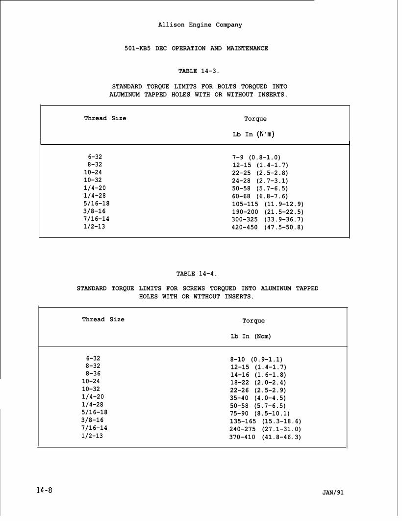
Allison Engine Company
501-KB5 DEC OPERATION AND MAINTENANCE
TABLE 14-3.
STANDARD TORQUE LIMITS FOR BOLTS TORQUED INTOALUMINUM TAPPED HOLES WITH OR WITHOUT INSERTS.
Thread Size Torque
Lb In (N”m)
6-328-3210-2410-321/4-201/4-285/16-183/8-167/16-141/2-13
7-9 (0.8-1.0)12-15 (1.4-1.7)22-25 (2.5-2.8)24-28 (2.7-3.1)50-58 (5.7-6.5)60-68 (6.8-7.6)105-115 (11.9-12.9)190-200 (21.5-22.5)300-325 (33.9-36.7)420-450 (47.5-50.8)
TABLE 14-4.
STANDARD TORQUE LIMITS FOR SCREWS TORQUED INTO ALUMINUM TAPPEDHOLES WITH OR WITHOUT INSERTS.
Thread Size Torque
Lb In (Nom)
6-32 8-10 (0.9-1.1)8-32 12-15 (1.4-1.7)8-36 14-16 (1.6-1.8)
10-24 18-22 (2.0-2.4)10-32 22-26 (2.5-2.9)1/4-20 35-40 (4.0-4.5)1/4-28 50-58 (5.7-6.5)5/16-18 75-90 (8.5-10.1)3/8-16 135-165 (15.3-18.6)7/16-14 240-275 (27.1-31.0)1/2-13 370-410 (41.8-46.3)
.14-8 JAN/91
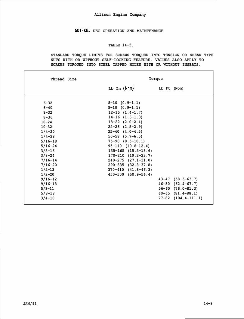
Allison Engine Company
501-KB5 DEC OPERATION AND MAINTENANCE
TABLE 14-5.
SCREWS TORQUED INTO STEEL TAPPED HOLES WITH OR WITHOUT INSERTS.
STANDARD TORQUE LIMITS FOR SCREWS TORQUED INTO TENSION OR SHEAR TYPENUTS WITH OR WITHOUT SELF-LOCKING FEATURE. VALUES ALSO APPLY TO
JAN/91 14-9
Thread Size Torque
Lb In (N”m) Lb Ft (Nom)
6-32 8-10 (0.9-1.1)6-40 8-10 (0.9-1.1)8-32 12-15 (1.4-1.7)8-36 14-16 (1.6-1.8)
10-24 18-22 (2.0-2.4)10-32 22-26 (2.5-2.9)1/4-20 35-40 (4.0-4.5)1/4-28 50-58 (5.7-6.5)5/16-18 75-90 (8.5-10.1)5/16-24 95-110 (10.8-12.4)3/8-16 135-165 (15.3-18.6)3/8-24 170-210 (19.2-23.7)7/16-14 240-275 (27.1-31.0)7/16-20 290-335 (32.8-37.8)1/2-13 370-410 (41.8-46.3)1/2-20 450-500 (50.9-56.4)9/16-12 43-47 (58.3-63.7)9/16-18 46-50 (62.4-67.7)5/8-11 56-60 (76.0-81.3)5/8-18 60-65 (81.4-88.1)3/4-10 77-82 (104.4-111.1)
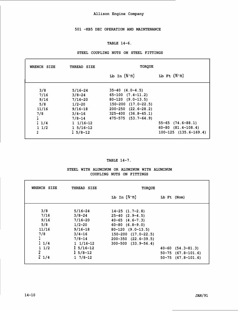
Allison Engine Company
501 -KB5 DEC OPERATION AND MAINTENANCE
TABLE 14-6.
STEEL COUPLING NUTS ON STEEL FITTINGS
WRENCH SIZE THREAD SIZE TORQUE
Lb In (N”m) Lb Ft (N”m)
3/87/169/165/8
11/167/811 1/41 1/22
5/16-243/8-247/16-201/2-209/16-183/4-167/8-141 1/16-121 5/16-121 5/8-12
35-40 (4.0-4.5)65-100 (7.4-11.2)80-120 (9.0-13.5)150-200 (17.0-22.5)200-250 (22.6-28.2)325-400 (36.8-45.1)475-575 (53.7-64.9)
55-65 (74.6-88.1)60-80 (81.4-108.4)100-125 (135.6-169.4)
TABLE 14-7.
STEEL WITH ALUMINUM OR ALUMINUM WITH ALUMINUMCOUPLING NUTS ON FITTINGS
WRENCH SIZE THREAD SIZE TORQUE
Lb In (Nom) Lb Ft (Nom)
3/87/169/165/8
11/167/811 1/41 1/2
: 1/4
5/16-243/8-247/16-201/2-209/16-183/4-167/8-141 1/16-121 5/16-121 5/8-121 7/8-12
14-25 (1.7-2.8)25-40 (2.9-4.5)40-65 (4.6-7.3)60-80 (6.8-9.0)80-120 (9.0-13.5)150-200 (17.0-22.5)200-350 (22.6-39.5)300-500 (33.9-56.4)
40-60 (54.3-81.3)50-75 (67.8-101.6)50-75 (67.8-101.6)
14-10 JAN/91
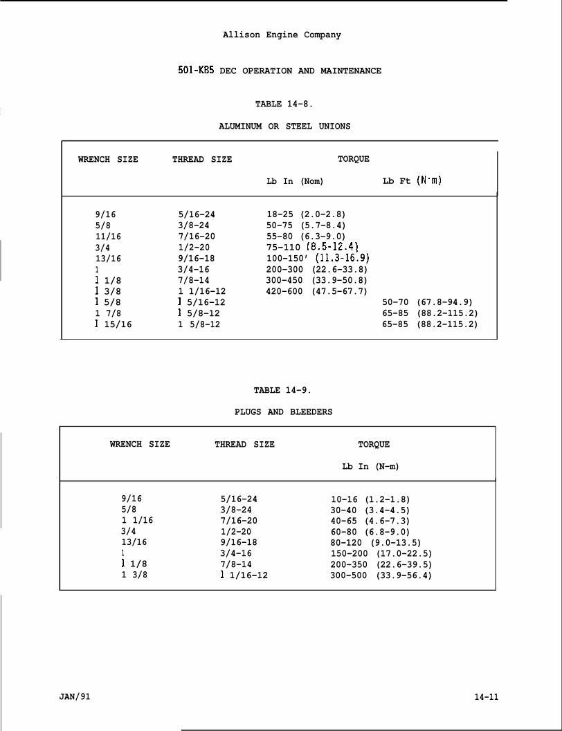
Allison Engine Company
501-KB5 DEC OPERATION AND MAINTENANCE
ITABLE 14-8.
ALUMINUM OR STEEL UNIONS
WRENCH SIZE THREAD SIZE TORQUE
Lb In (Nom) Lb Ft (Nom)
9/165/811/163/413/1611 1/81 3/81 5/81 7/81 15/16
5/16-243/8-247/16-201/2-209/16-183/4-167/8-141 1/16-121 5/16-121 5/8-121 5/8-12
18-25 (2.0-2.8)50-75 (5.7-8.4)55-80 (6.3-9.0)75-110 (8.5-12.4)100-150’ (11.3-16:9)200-300 (22.6-33.8)300-450 (33.9-50.8)420-600 (47.5-67.7)
50-70 (67.8-94.9)65-85 (88.2-115.2)65-85 (88.2-115.2)
TABLE 14-9.
PLUGS AND BLEEDERS
WRENCH SIZE THREAD SIZE TORQUE
Lb In (N-m)
9/165/81 1/163/413/1611 1/81 3/8
5/16-243/8-247/16-201/2-209/16-183/4-167/8-141 1/16-12
10-16 (1.2-1.8)30-40 (3.4-4.5)40-65 (4.6-7.3)60-80 (6.8-9.0)80-120 (9.0-13.5)150-200 (17.0-22.5)200-350 (22.6-39.5)300-500 (33.9-56.4)
JAN/91 14-11
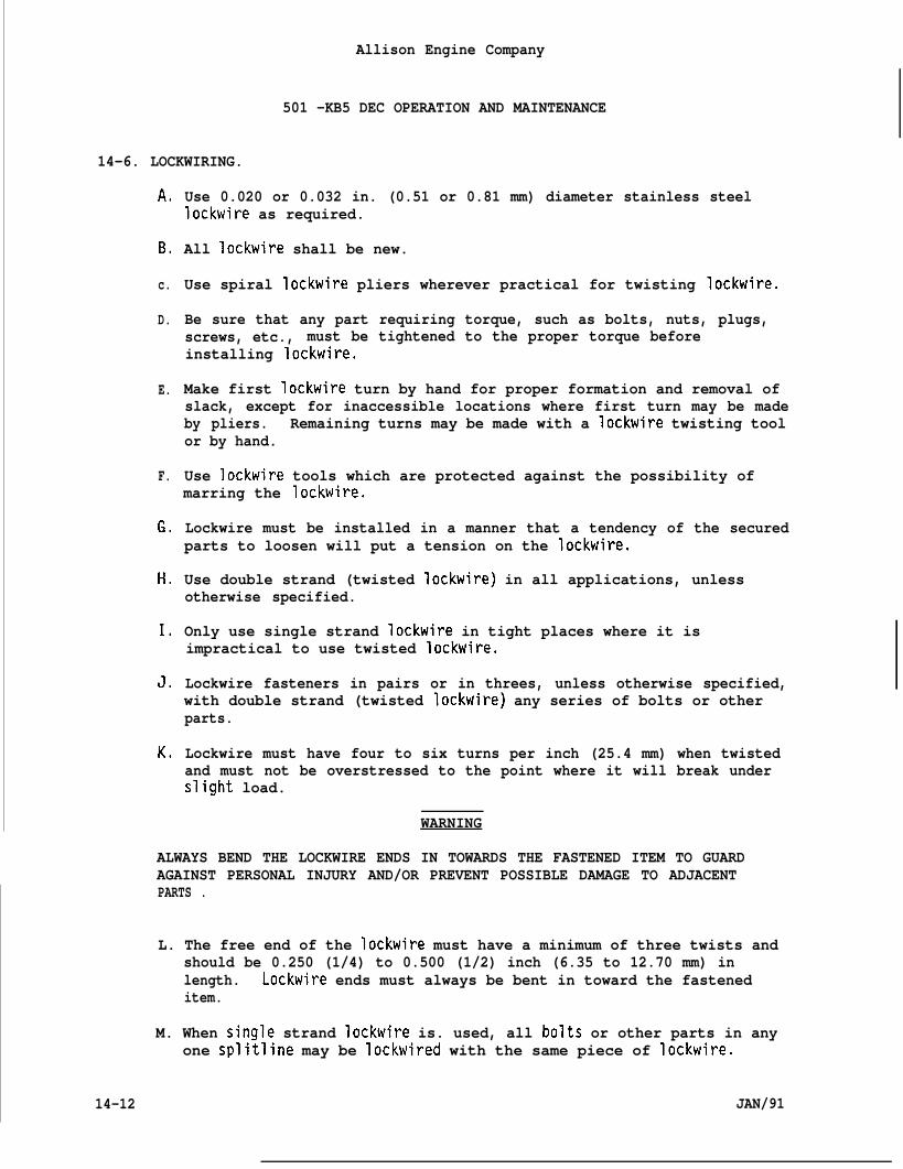
Allison Engine Company
501 -KB5 DEC OPERATION AND MAINTENANCE
14-6. LOCKWIRING.
A.
B.
c.
D.
E.
F.
G.
H,
1.
J,
K,
Use 0.020 or 0.032 in. (0.51 or 0.81 mm) diameter stainless steellockwire as required.
All lockwire shall be new.
Use spiral lockwire pliers wherever practical for twisting lockwire.
Be sure that any part requiring torque, such as bolts, nuts, plugs,screws, etc., must be tightened to the proper torque beforeinstalling lockwire.
Make first lockwire turn by hand for proper formation and removal ofslack, except for inaccessible locations where first turn may be madeby pliers. Remaining turns may be made with a Iockwire twisting toolor by hand.
Use lockwire tools which are protected against the possibility ofmarring the lockwire.
Lockwire must be installed in a manner that a tendency of the securedparts to loosen will put a tension on the lockwire.
Use double strand (twisted lockwire) in all applications, unlessotherwise specified.
Only use single strand lockwire in tight places where it isimpractical to use twisted lockwire.
Lockwire fasteners in pairs or in threes, unless otherwise specified,with double strand (twisted lockwire) any series of bolts or otherparts.
Lockwire must have four to six turns per inch (25.4 mm) when twistedand must not be overstressed to the point where it will break underslight load.
WARNING
ALWAYS BEND THE LOCKWIRE ENDS IN TOWARDS THE FASTENED ITEM TO GUARDAGAINST PERSONAL INJURY AND/OR PREVENT POSSIBLE DAMAGE TO ADJACENTPARTS .
L. The free end of the lockwire must have a minimum of three twists andshould be 0.250 (1/4) to 0.500 (1/2) inch (6.35 to 12.70 mm) inlength. Lockwire ends must always be bent in toward the fasteneditem.
M. When single strand lockwire is. used, all bolts or other parts in anyone splitline may be lockwired with the same piece of lockwire.
14-12 JAN/91
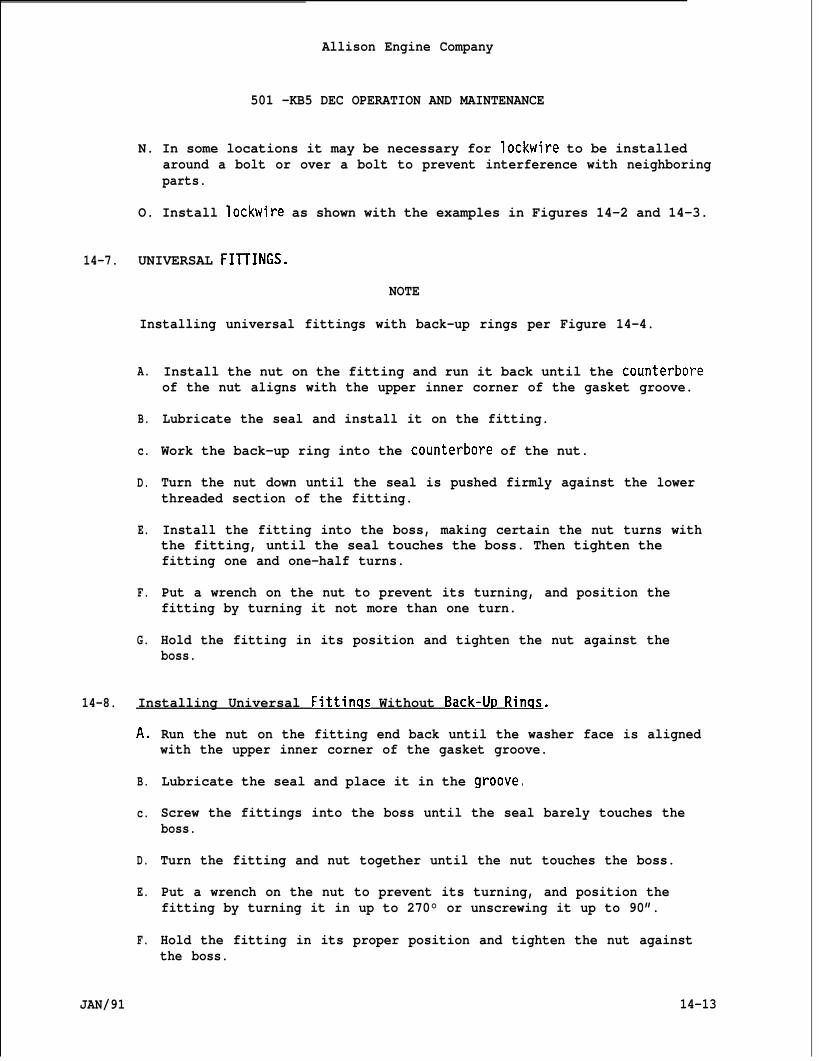
Allison Engine Company
501 -KB5 DEC OPERATION AND MAINTENANCE
N. In some locations it may be necessary for lockwire to be installedaround a bolt or over a bolt to prevent interference with neighboringparts.
O. Install Iockwire as shown with the examples in Figures 14-2 and 14-3.
14-7. UNIVERSAL FIllINGS.
NOTE
Installing universal fittings with back-up rings per Figure 14-4.
A.
B.
c.
D.
E.
F.
G.
Install the nut on the fitting and run it back until the counterboreof the nut aligns with the upper inner corner of the gasket groove.
Lubricate the seal and install it on the fitting.
Work the back-up ring into the counterbore of the nut.
Turn the nut down until the seal is pushed firmly against the lowerthreaded section of the fitting.
Install the fitting into the boss, making certain the nut turns withthe fitting, until the seal touches the boss. Then tighten thefitting one and one-half turns.
Put a wrench on the nut to prevent its turning, and position thefitting by turning it not more than one turn.
Hold the fitting in its position and tighten the nut against theboss.
14-8. Installing Universal Fittinas Without Back-U~ Rinqs.
A.
B.
c.
D.
E.
F.
JAN/91
Run the nut on the fitting end back until the washer face is alignedwith the upper inner corner of the gasket groove.
Lubricate the seal and place it in the groove
Screw the fittings into the boss until the seal barely touches theboss.
Turn the fitting and nut together until the nut touches the boss.
Put a wrench on the nut to prevent its turning, and position thefitting by turning it in up to 270° or unscrewing it up to 90”.
Hold the fitting in its proper position and tighten the nut againstthe boss.
14-13
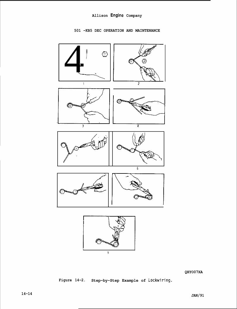
Allison Engine Company
501 -KB5 DEC OPERATION AND MAINTENANCE
4,,. (9f
1 L
6
1 I9
QHYO07XA
Figure 14-2. Step-by-Step Example of Lockwiring.
14-14 JAN/91
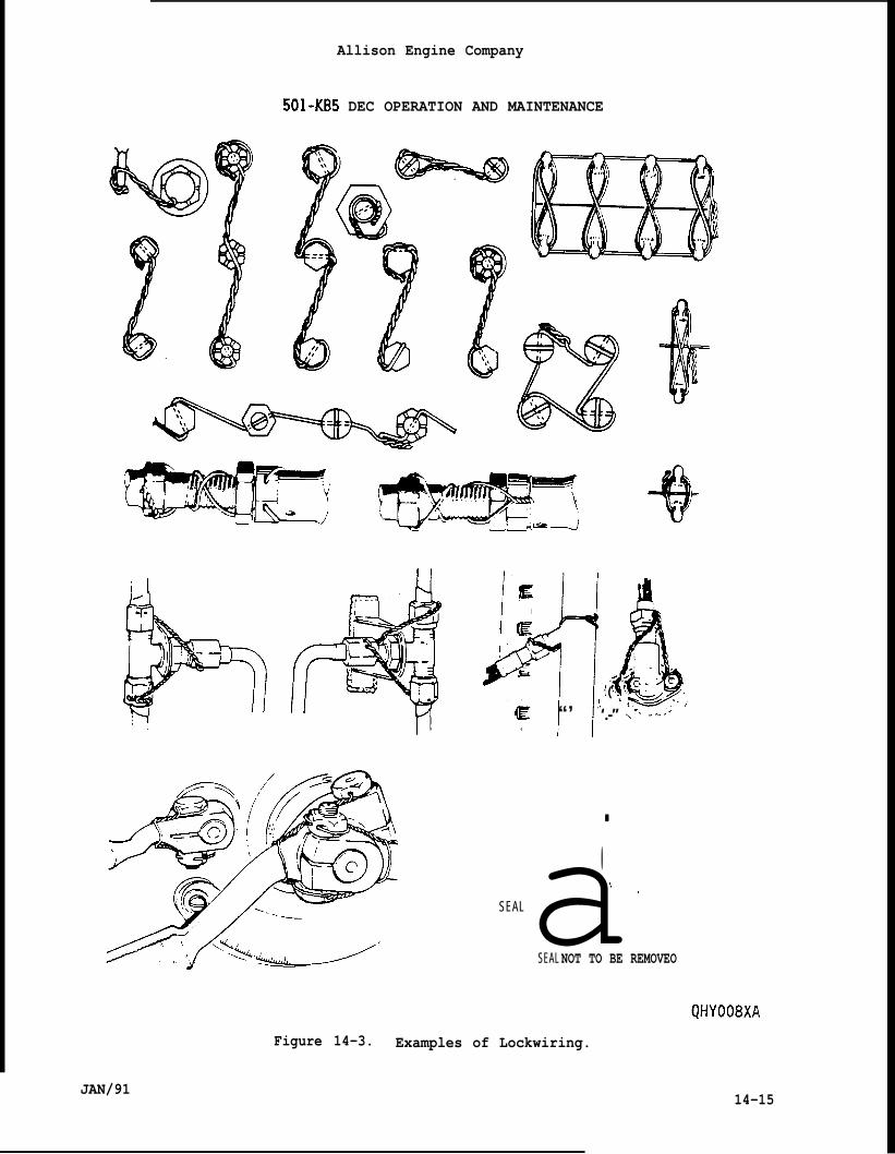
Allison Engine Company
501-KB5 DEC OPERATION AND MAINTENANCE
J~lt!t!lbIE
E,1’
h. - .
( “:.,c L_’ c
‘,- . /:
E “’ ‘.-” -“’
a.-:. :.SEAL
SEAL NOT TO BE REMOVEO
JAN/91
Figure 14-3. Examples of Lockwiring.
14-15
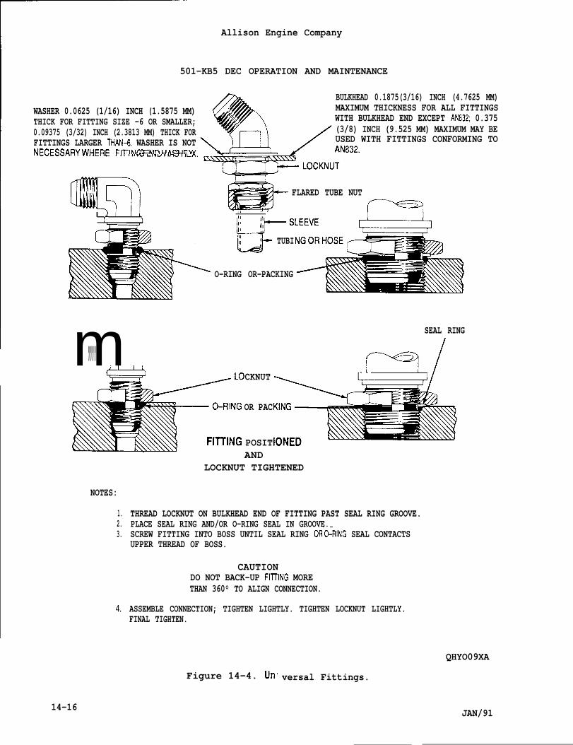
Allison Engine Company
501-KB5 DEC OPERATION AND MAINTENANCE
NECESSARYWHERE FITT,,.”k,.w,,mU,,_ ~
,,,’.,~.nll iii!!%,,.
BULKHEAD 0.1875(3/16) INCH (4.7625 MM)WASHER 0.0625 (1/16) INCH (1.5875 MM) MAXIMUM THICKNESS FOR ALL FITTINGSTHICK FOR FITTING SIZE -6 OR SMALLER; WITH BULKHEAD END EXCEPT AN832; 0.3750.09375 (3/32) INCH (2.3813 MM) THICK FOR (3/8) INCH (9.525 MM) MAXIMUM MAY BEFITTINGS LARGER THAN+ WASHER IS NOT USED WITH FITTINGS CONFORMING TO
rlNC I= NIIMAC UEY
L FLARED TUBE NUT
(-T) I 1 1 ,.
,+ , I I[ lL-!r--sLEEvE ~II ;
Lk
TUBI
O-RING OR-PACKING
m,,,, , SEAL RING
f=dCKNUT
OR PAC
POSITAND
LOCKNUT TIGHTENED
NOTES:
1.2.3.
4.
14-16
THREAD LOCKNUT ON BULKHEAD END OF FITTING PAST SEAL RING GROOVE.PLACE SEAL RING AND/OR O-RING SEAL IN GROOVE.SCREW FITTING INTO BOSS UNTIL SEAL RING Oi-&-RING SEAL CONTACTSUPPER THREAD OF BOSS.
CAUTIONDO NOT BACK-UP FllllNG MORETHAN 360° TO ALIGN CONNECTION.
FINAL TIGHTEN.
Figure 14-4. Un
ASSEMBLE CONNECTION; TIGHTEN LIGHTLY. TIGHTEN LOCKNUT LIGHTLY.
versal Fittings.
QHYO09XA
JAN/91
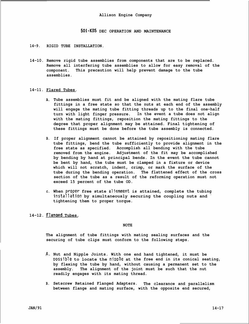
Allison Engine Company
501-KB5 DEC OPERATION AND MAINTENANCE
14-9. RIGID TUBE INSTALLATION.
14-10. Remove rigid tube assemblies from components that are to be replaced.Remove all interfering tube assemblies to allow for easy removal of thecomponent. This precaution will help prevent damage to the tubeassemblies.
14-11. Flared Tubes.
A.
B.
c.
Tube assemblies must fit and be aligned with the mating flare tubefittings in a free state so that the nuts at each end of the assemblywill engage the mating tube fitting threads up to the final one-halfturn with light finger pressure. In the event a tube does not alignwith the mating fittings, reposition the mating fittings to thedegree that proper alignment may be attained. Final tightening ofthese fittings must be done before the tube assembly is connected.
If proper alignment cannot be attained by repositioning mating flaretube fittings, bend the tube sufficiently to provide alignment in thefree state as specified. Accomplish all bending with the tuberemoved from the engine. Adjustment of the fit may be accomplishedby bending by hand at principal bends. In the event the tube cannotbe bent by hand, the tube must be clamped in a fixture or devicewhich will not scratch, indent, crimp, or mark the surface of thetube during the bending operation. The flattened effect of the crosssection of the tube as a result of the reforming operation must notexceed 15 percent of the tube OD.
When Drot)er free state alianment is attained, complete the tubinginstaila~ion by simultaneously securing the coupling nuts and -
tightening them to proper torque.
14-12. Flanqed Tubes.
NOTE
The alignment of tube fittings withsecuring of tube clips must conform
A.
B.
JAN/91
Nut and Nipple Joints. With oneDossible to locate the nipple at
mating sealing surfaces and theto the following steps.
end hand tightened, it must bethe free end in its conical seating,
by flexing the tube by hand, without causing a permanent set to theassembly. The alignment of the joint must be such that the nutreadily engages with its mating thread.
Setscrew Retained Flanged Adapters. The clearance and parallelismbetween flange and mating surface, with the opposite end secured,
14-17
Allison Engine Company
501-KB5 DEC OPERATION AND MAINTENANCE
c.
D.
must be such that the total flange area contact can be achieved byflexing the tube by hand without causing a permanent set to theassembly. Flange clearance holes must line up with mating holes thatbolts can be fitted without subjecting the tube to a torsional load.
Clipping Points. Locate clips to securing points such that thesetscrews can be fitted by flexing the tube by hand without causing apermanent set to the assembly. Tubes which fail to meet thisrequirement may be removed from the engine and reformed as follows:
1. Tubes must be clamped in a fixture which will not scratch, indent,crimp or mark the surface of the tube during the bendingoperation.
2. Retention of the tube during bending should be made in a mannerwhich does not permit bending or torsional loads across welded orbrazed areas.
3. Tubes which can be corrected for fit only by submitting weldedareas to bending or torsional loads must be inspected by X-ray orZyglo for any evidence of weld or braze fracture prior toinstallation on the engine.
4. Reformed tubes must meet the requirements of Steps A. or B.
When removal of the tube from the enqine would result in excessivelost time due to the need for teardo;n and rebuild, the tube may bereformed while attached to the engine if the following precautionsare followed:
1.
2.
3.
Bending and torsional loads must not be applied across welded orbrazed areas.
The tube attachment points are to be loosened after bending.(Attachment points which are inaccessible due to the state ofassembly are excluded.)
Reformed tubes must meet the requirements of Steps A. and B.
14-13. USE OF TORQUE WRENCHES.
A.
B.
When using a torque wrench with a pivoted handle, the handles must bebalanced so that pressure is applied only at the pivot.
In some ar)~lications, it is necessary to use a s~ecial extension oradapter wrench with a standard torqu~ wrench as shown in Figure14-5. When the axis of the adapter or extension is positioned 90°from the axis of the torque wrench (as shown in dotted lines, Figure14-5), no correction factor is required.
14-18 JAN/91
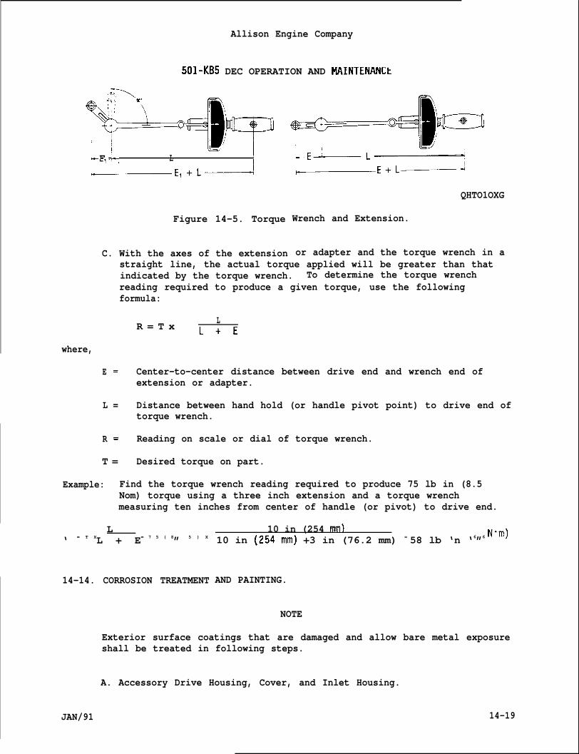
Allison Engine Company
501-KB5 DEC OPERATION AND MAINTENANLt
t-E1 ‘-, L I
+—---E1+L~
Figure 14-5. Torque
C. With the axes of the extension
QHTO1OXG
Wrench and Extension.
or adapter and the torque wrench in astraight line, the actual torque applied will be greater than thatindicated by the torque wrench. To determine the torque wrenchreading required to produce a given torque, use the followingformula:
R = T x LL+E
where,
E = Center-to-center distance between drive end and wrench end ofextension or adapter.
L = Distance between hand hold (or handle pivot point) to drive end oftorque wrench.
R = Reading on scale or dial of torque wrench.
T = Desired torque on part.
Example: Find the torque wrench reading required to produce 75 lb in (8.5Nom) torque using a three inch extension and a torque wrenchmeasuring ten inches from center of handle (or pivot) to drive end.
L‘ = T XL + E= 7 5 ( 8” 5 ) X
14-14. CORROSION TREATMENT
10 in (254 mm)10 in (254mm) +3 in (76.2 mm) = 58 lb ‘n ‘6”6 ‘“m)
AND PAINTING.
NOTE
Exterior surface coatings that are damaged and allow bare metal exposureshall be treated in following steps.
A. Accessory Drive Housing, Cover, and Inlet Housing.
JAN/91 14-19
1.
2.
Allison Engine Company
501-KB5 DEC OPERATION AND MAINTENANCE
Repair the damaged area, as required, with emery cloth.
Swab area to be treatedarea with the followingbrush.
ASOLUTION OF ALODINE, NITRICAND CLOTHING. OPERATORS MUSTGLOVES, APRONS, ETC.
with clean water. While still wet, coatliquid solution using a nylon bristle
WARN ING
ACID, AND WATER IS INJURIOUS TO THE SKINBE ADEQUATELY PROTECTED BY GOGGLES, RUBBER
NOTE
The liquid solution is made of3 oz (85 grams) of Alodine No. 1200(American Chemical Paint Co., Ambler, Pennsylvania) and 1/2 fluid oz(14.8 ml) of nitric acid (cone) (HN03) per gal(3.8 L) of water.
3. Both the part and liquid solution must be maintained at roomtemperature. Allow the liquid solution to remain on area for atleast one to not more than five minutes, but in no case should itdry on the part.
4. Rinse or swab the liquid solution coated area thoroughly withclean water to completely remove all remaining solution.
CAUTION
ALL BRUSHES AND SWABS MUST BE WATER RINSED TO MINIMIZE FIRE HAZARD.
5.
6.
7.
8.
Blow treated surface dry with clean, dry, filtered shop air.
Handle dried treated housing with clean rubber gloves.
Keep time interval between cleaning and painting to a minimum.
Mask housing for painting so all outside surfaces can be coatedexcept tapped holes, dowel pins, bolt clearance holes, andmachined surfaces.
NOTE
The mixed paint has a limited pot life of eight hours at roomtemperature. The pot life may be extended by keeping container tightlycovered and in a refrigerator.
14-20 JAN/91
14-15.
JAN/91
Allison Engine Company ,
501-KB5 DEC OPERATION AND MAINTENANCE
9. The paint, Actithane WC 100, FSN 8010-831-5934, is a two componentpackage which requires mixing. Blend three parts paint by volumewith one part activator by volume. Thoroughly blend the mixtureand allow it to age at least fifteen minutes before using.
10. Brush or spray the part with two thoroughly blended and mixedcoats of paint. Allow the first coat to air dry for twentyminutes. Localize heat cure after the second coat of paint perpaint manufacturer requirements.
B. Compressor Case and Diffuser.
1.
2.
3.
Thoroughly swab damaged areas to be treated with trichloroethyleneand air dry for five to ten minutes.
Repair the damaged area with emery cloth, into a slightly largerarea and feather the edges.
Clean the abraded areas with solvent and dry with clean, filteredcompressed air.
NOTE
Sermetel 196 is a product of Sermetel Inc., Sub of Teleflex Inc., 155 S.Limerick Rd., Limerick Pennsylvania 19468.
4. Apply aluminum coating, Sermetel 196, in two coats with a thirtyto sixty minute air dry period between coats.
DYE PENETRANT INSPECTION.
NOTE
Use either the Flaw Finder dye check kit, made by the Met-L-CheckCompany, 1639 Euclid St., Santa Monica, California 90404, or theFluorescent Dye Penetrant Kit, P/NA-43.
A.
B.
c.
D.
Thoroughly clean the area to be inspected with any approved solvent.Dry the area of the part to be inspected, with clean, filteredcompressed air.
Dry brush the cleaned area to remove oxide and carbon deposits.
Brush the dye penetrant on the area and allow the dye penetrant tostand for five to ten minutes.
Wipe off the penetrant with a clean cloth. Dry brush the area toremove all surface penetrant.
14-21
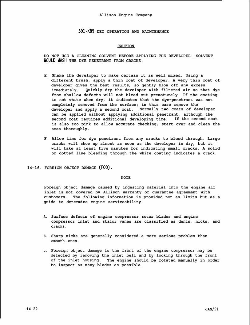
Allison Engine Company
501-KB5 DEC OPERATION AND MAINTENANCE
CAUTION
DO NOT USE A CLEANING SOLVENT BEFORE APPLYING THE DEVELOPER. SOLVENTUOULD WASH THE DYE PENETRANT FROM CRACKS.
E. Shake the developer to make certain it is well mixed. Using adifferent brush, apply a thin coat of developer. A very thin coat ofdeveloper gives the best results, so gently blow off any excessimmediately. Quickly dry the developer with filtered air so that dyefrom shallow defects will not bleed out prematurely. If the coatingis not white when dry, it indicates that the dye-penetrant was notcompletely removed from the surface; in this case remove thedeveloper and apply a second coat. Normally two coats of developercan be applied without applying additional penetrant, although thesecond coat requires additional developing time. If the second coatis also too pink to allow accurate checking, start over and clean thearea thoroughly.
F. Allow time for dye penetrant from any cracks to bleed through. Largecracks will show up almost as soon as the developer is dry, but itwill take at least five minutes for indicating small cracks. A solidor dotted line bleeding through the white coating indicates a crack.
14-16. FOREIGN OBJECT DAMAGE (FOD).
NOTE
Foreign object damage caused by ingesting material into the engine airinlet is not covered by Allison warranty or guarantee agreement withcustomers. The following information is provided not as limits but as aguide to determine engine serviceability.
A.
B.
c.
14-22
Surface defects of engine compressor rotor blades and enginecompressor inlet and stator vanes are classified as dents, nicks, andcracks.
Sharp nicks are generally considered a more serious problem thansmooth ones.
Foreign object damage to the front of the engine compressor may bedetected by removing the inlet bell and by looking through the frontof the inlet housing. The engine should be rotated manually in orderto inspect as many blades as possible.
JAN/91
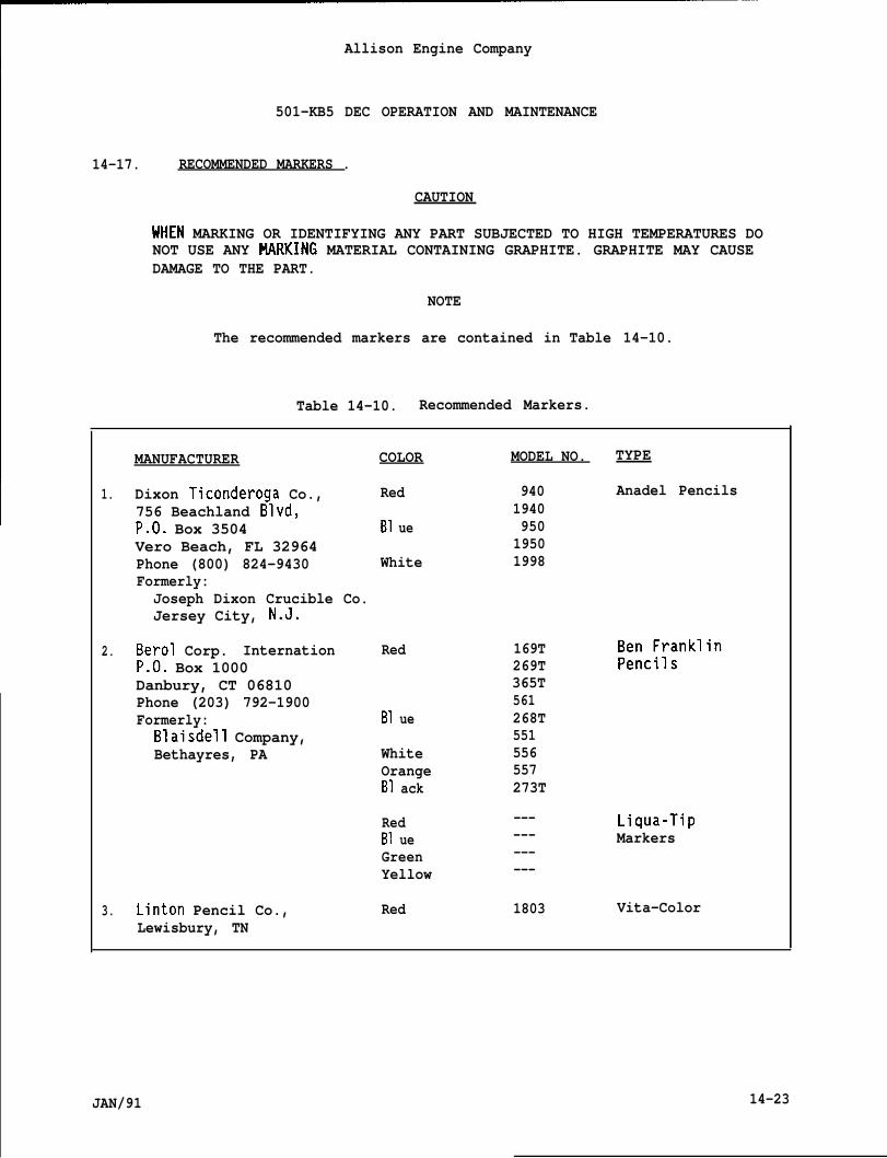
Allison Engine Company
501-KB5 DEC OPERATION AND MAINTENANCE
14-17. RECOMMENDED MARKERS .
CAUTION
UHEN MARKING OR IDENTIFYING ANY PART SUBJECTED TO HIGH TEMPERATURES DONOT USE ANY tlARKING MATERIAL CONTAINING GRAPHITE. GRAPHITE MAY CAUSEDAMAGE TO THE PART.
NOTE
The recommended markers are contained in Table 14-10.
Table 14-10. Recommended Markers.
MANUFACTURER COLOR MODEL NO. TYPE
1. Dixon Ticonderoga Co., Red 940 Anadel Pencils756 Beachland Blvd, 1940P.O. Box 3504 B1 ue 950Vero Beach, FL 32964 1950Phone (800) 824-9430 White 1998Formerly:Joseph Dixon Crucible Co.Jersey City, N.J.
2. Berol Corp. Internation Red 169TP.O. Box 1000 269TDanbury, CT 06810 365TPhone (203) 792-1900 561Formerly: B1 ue 268T
Blaisdell Company, 551Bethayres, PA White 556
Orange 557B1 ack 273T
Red --- Liqua-TipB1 ue --- MarkersGreen ---Yellow ---
3. Linton Pencil Co., Red 1803 Vita-ColorLewisbury, TN
JAN/91 14-23
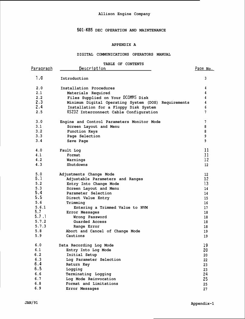
Allison Engine Company
501-KB5 DEC OPERATION AND MAINTENANCE
ParacvaDh
1.0
2.02.12.2
;::2.5
3.03.13.23.33.4
4.04.14.24.3
5.05.15.25.3
i::5.65.6.1
::; .15.7.25.7.35.85.9
6.06.16.26.3
:::6.66.76.86.9
JAN/91
APPENDIX A
DIGITAL COMMUNICATIONS OPERATORS MANUAL
TABLE OF CONTENTSl)escrir)tion
Introduction
Installation ProceduresMaterials RequiredFiles Supplied on Your DCOMMS DiskMinimum Digital Operating System (DOS) RequirementsInstallation for a Floppy Disk SystemRS232 Interconnect Cable Configuration
Engine and Control Parameters Monitor ModeScreen Layout and MenuFunction KeysPage SelectionSave Page
Fault LogFormatWarningsShutdowns
Adjustments Change ModeAdjustable Parameters and RangesEntry Into Change ModeScreen Layout and MenuParameter SelectionDirect Value EntryTrimming
Entering a Trimmed Value to NVMError Messages
Wrong PasswordGuarded AccessRange Error
Abort and Cancel of Change ModeCautions
Data Recording Log ModeEntry Into Log ModeInitial SetupLog Parameter SelectionReturn KeyLoggingTerminating LoggingLog Mode ReinvocationFormat and LimitationsError Messages
Paqe No.
3
444467
78899
11
;;12
12
::1414151617181818181919
;:20222323
;;2527
Appendix-1
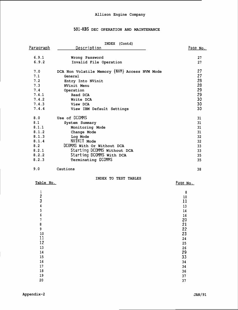
I
Paraqra~h
6.9.16.9.2
7.07.17.27.37.47.4.17.4.27.4.37.4.4
8.08.18.1.18.1.28.1.38.1.4
Allison Engine Company
501-KB5 DEC OPERATION AND MAINTENANCE
INDEX (Contd)Descrir)tion
Wrong PasswordInvalid File Operation
DCA Non Volatile Memory (NVM) Access NVM ModeGeneralEntry Into NVinitNVinit MenuOperation
Read DCAWrite DCAView DCAView IBM Default Settings
Use of DCOMMSSystem Summary
Monitoring ModeChange ModeLog ModeNVINIT Mode
I 8.2 DCOMMS With Or Without DCA8.2.1 Startina DCOMMS Without DCA8.2.2 Startin~ DCOMMS With DCA8.2.3 Terminating DCOMMS
9.0 Cautions
INDEX TO TEST TABLESTable No.
1
:45678910
;;1314151617181920
Appendix-2
Paae No.
2727
31313131323233333535
38
Paqe No.
81011131416
;;
;:242526
;:3434363737
JAN/91
Allison Engine Company
501-KB5 DEC OPERATION AND MAINTENANCE
APPENDIX A
DIGITAL COMMUNICATIONS OPERATORS MANUAL
1.0 INTRODUCTION .
A. This ar)~endix describes the Digital Communications (DCOMMS) packageas it is used with the Allison-501-KB5 engine using a Hawker SiddeleyDynamics Engineering, LTD (HSDE) Digital Control Assembly (DCA).DCOMMS utilizes the RS232C serial interface via an IBM compatiblepersonal computer (PC) setup.
B. The material herein is adapted from a HSDE document entitled, DIGICONIBM Communications Operator Manual.
C. The DCOMMS package provides the following key features:
1. On line monitoring of engine parameters (both interfaced directly
2
3
to the DCA and computed by the DCA), with engineering unit display.
On line adjustment of parameters in either engineering unit formator by up and down trimming. Adjustment is both password protectedand limited to within prescribed upper and lower boundaries, forsafety reasons.
On line data lominq of UP to 8 parameters at a time with aminimum time re;;lu~ion of approximately 1 second (period isoperator selectable) for up to 1000 records (number of scansrecorded). The logged data may be directed to either disk file,serial ports or printer.
4. Selected monitoring pages may be saved at any time to disk orexternal device (e.g. printer) for off line analysis.
5. Via Non Volatile Memory (NVM) initialization functions, manycontrol systems may be simply and efficiently set up.
6. All operator applied changes (setpoints etc.) are recorded inter-nally (within the IBM) and may, if required, be saved to disk ontermination of the communications session via automatic con-figuration file reconstruction, such that changes may be recorded.
7. A TEST mode allows verification of an operator configuration filebefore committing the system to the final control environment. Inthis mode, the IBM and DCOMMS package act in a stand alone mannerwithout the need for a DCA series controller.
8. All Tables in this Appendix were generated in TEST mode.Numerical values have no significant meaning. The Tables showexamples of procedural functionality and not engine configurationspecifics. They are test examples only.
JAN/91 Appendix-3

Allison Engine Company
501-KB5 DEC
2.0 INSTALLATION PROCEDURES.
2.1 MATERIALS REQUIRED.
OPERATION AND MAINTENANCE
A. To successfully use the DCOMMS package, you need:
1. The DCOMMS package: a single disk labeled, DCOMMS .
2. An IBM (or fully compatible) personal computer (PC) equipped witha minimum of:
;:c.d.e.
f.
2.2 FILES ON
256K of RAMMonochrome Display Adapter (MDA)one disk drive (either floppy or hard)one Serial (RS232) port configured to COM1IBM Personal Computer DOS version 2.0 or hfor IBM compatibles)A printer (highly recommended).
YOUR DCOMMS DISK.
gher (or equivalent
A. The following are the files provided on your master DCOMMS disk:
1.
2.
3.
4.
DCOMMS.EXEThe Digital Communications executable program.
DCOMMS.OV1The password file containing encrypted passwords used byDCOMMS.EXE for parameter adjustments, NVM changes and historicaldata logging modes. The passwords are not viewable and may not bealtered.
CONFIGURATIONThis is the master configuration file which acts as a data card,providing parameter definitions for the system. The name of thisfile will vary.
README.NOWThis is an on board abbreviation of this report for easy access.
2.3 MINIMUM DIGITAL OPERATING SYSTEM (DOS) REQUIREMENTS.
A. In order to successfully run the DCOMMS package, the following DOSprograms will be necessary. (Note that for some IBM compatiblecomputers, the program names may be slightly different, and that someprograms may indeed not be necessary).
1. COMMAND.COMThe DOS operating system itself.
Appendix-4 JAN/91
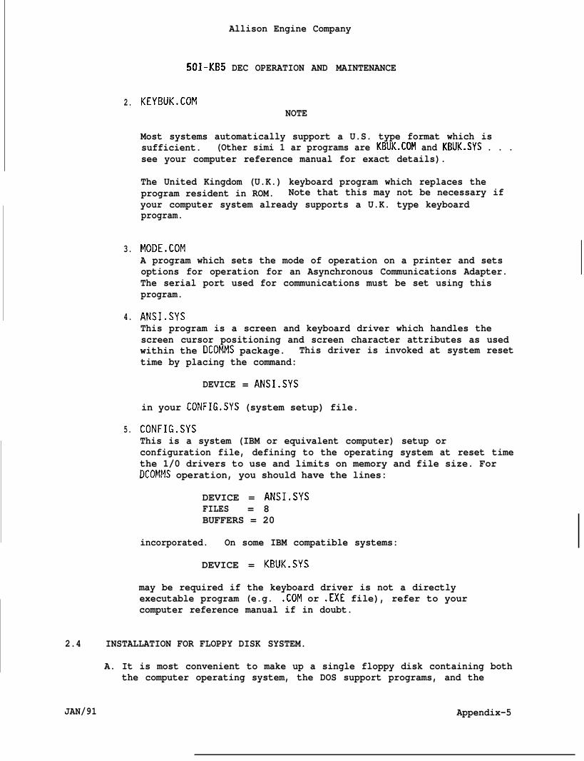
2.
3.
4.
5.
501-KB5
KEYBUK.COM
Allison Engine Company
DEC OPERATION AND MAINTENANCE
NOTE
Most systems automatically support a U.S. type format which issufficient. (Other simi 1 ar programs are KBUK.COM and KBUK.SYS . . .see your computer reference manual for exact details).
The United Kingdom (U.K.) keyboard program which replaces theprogram resident in ROM. Note that this may not be necessary ifyour computer system already supports a U.K. type keyboardprogram.
MODE.COMA program which sets the mode of operation on a printer and setsoptions for operation for an Asynchronous Communications Adapter.The serial port used for communications must be set using thisprogram.
ANSI.SYSThis program is a screen and keyboard driver which handles thescreen cursor positioning and screen character attributes as usedwithin the DCOMMS package. This driver is invoked at system resettime by placing the command:
DEVICE = ANSI.SYS
in your CONFIG.SYS (system setup) file.
CONFIG.SYSThis is a system (IBM or equivalent computer) setup orconfiguration file, defining to the operating system at reset timethe 1/0 drivers to use and limits on memory and file size. ForDCOMMS operation, you should have the lines:
DEVICE = ANSI.SYSFILES = 8BUFFERS = 20
incorporated. On some IBM compatible systems:
DEVICE = KBUK.SYS
may be required if the keyboard driver is not a directlyexecutable program (e.g. .COM or .EXE file), refer to yourcomputer reference manual if in doubt.
2.4 INSTALLATION FOR FLOPPY DISK SYSTEM.
A. It is most convenient to make up a single floppy disk containing boththe computer operating system, the DOS support programs, and the
JAN/91 Appendix-5
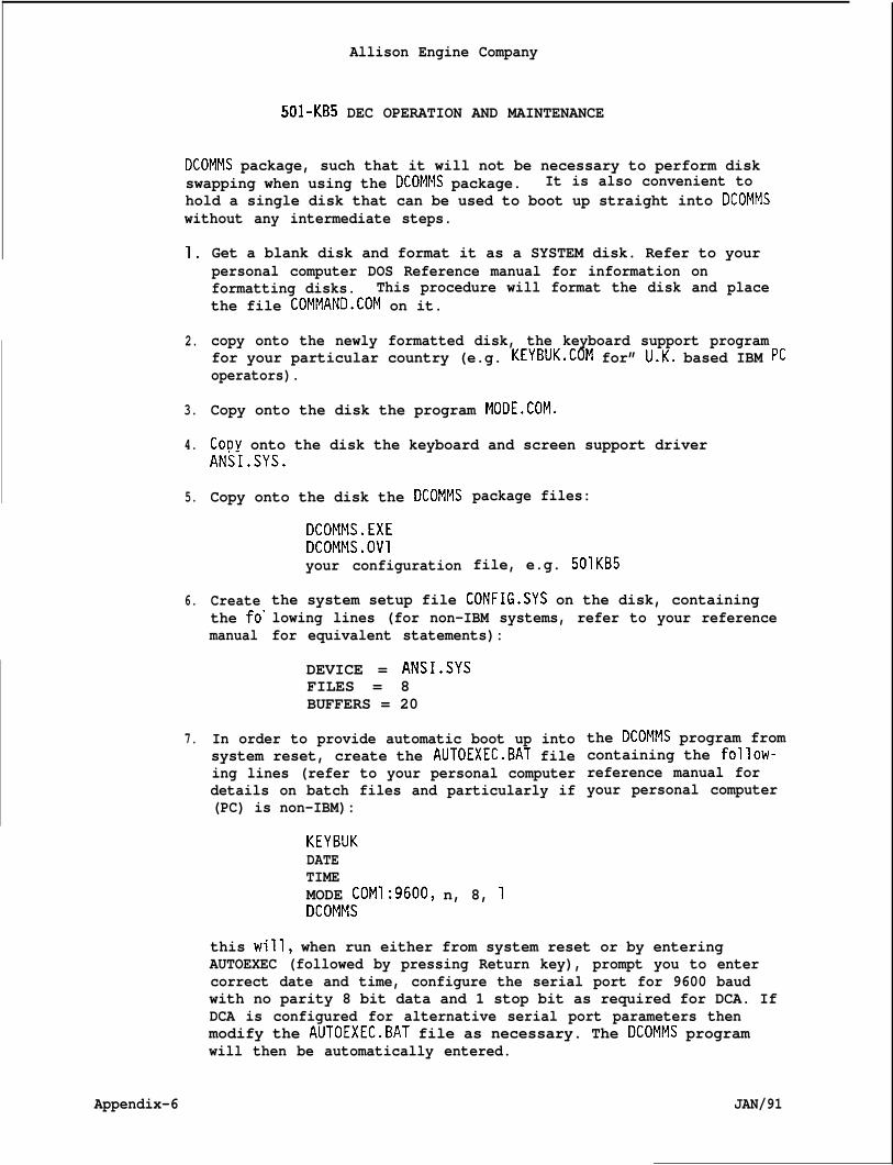
Allison Engine Company
501-KB5 DEC OPERATION AND MAINTENANCE
DCOMMS package, such that it will not be necessary to perform diskswapping when using the DCOMMS package. It is also convenient tohold a single disk that can be used to boot up straight into DCOMMSwithout any intermediate steps.
1.
2.
3.
4.
5.
6.
7.
Appendix-6
Get a blank disk and format it as a SYSTEM disk. Refer to yourpersonal computer DOS Reference manual for information onformatting disks. This procedure will format the disk and placethe file COMMAND.COM on it.
copy onto the newly formatted disk, the keyboard support programfor your particular country (e.g. KEYBUK.COM for” lJ.K. based IBM pcoperators).
Copy onto the disk the program MODE.COM.
CODY onto the disk the keyboard and screen support driverANS_i.SYS.
Copy onto the disk the DCOMMS
DCOMMS.EXEDCOMMS.OV1your configuration
package files:
file, e.g. 501KB5
Createthe fo”manual
the system setup file CONFIG.SYS on the disk, containinglowing lines (for non-IBM systems, refer to your referencefor equivalent statements):
DEVICE = ANSI.SYSFILES = 8BUFFERS = 20
In order to provide automatic boot up intosystem reset, create the AUTOEXEC.BAT fileing lines (refer to your personal computerdetails on batch files and particularly if(PC) is non-IBM):
KEYBUKDATETIMEMODE COM1:9600, n, 8, 1DCOMMS
the DCOMMS program fromcontaining the follow-reference manual foryour personal computer
this will, when run either from system reset or by enteringAUTOEXEC (followed by pressing Return key), prompt you to entercorrect date and time, configure the serial port for 9600 baudwith no parity 8 bit data and 1 stop bit as required for DCA. IfDCA is configured for alternative serial port parameters thenmodify the AUTOEXEC.BAT file as necessary. The DCOMMS programwill then be automatically entered.
JAN/91
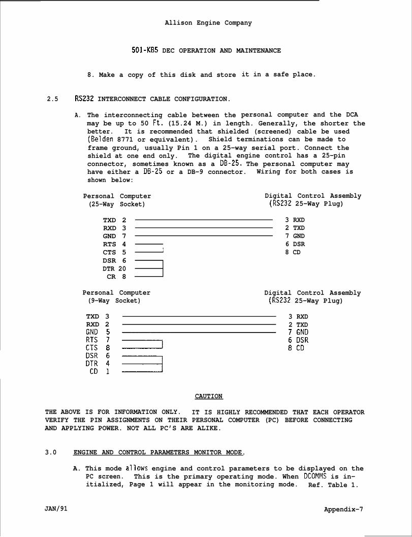
Allison Engine Company
501-KB5 DEC OPERATION AND MAINTENANCE
8. Make a copy of this disk and store
2.5 RS232 INTERCONNECT CABLE CONFIGURATION.
A. The interconnecting cable between the
it in a safe place.
personal computer and the DCAmay be up to 50 Ft; (15.24 M.) in length. Generally, the shorter thebetter. It is recommended that shielded (screened) cable be used(Belden 8771 or equivalent). Shield terminations can be made toframe ground, usually Pin 1 on a 25-way serial port. Connect theshield at one end only. The digital engine control has a 25-pinconnector, sometimes known as a DB-25. The personal computer mayhave either a DB-25 or a DB-9 connector. Wiring for both cases isshown below:
Personal Computer Digital Control Assembly(25-Way Socket) (RS232 25-Way Plug)
TXD 2RXD 3GND 7RTS 4CTS 5DSR 6DTR 20CR 8
3 RXD2 TXD7 GND
I6 DSR8 CD
Personal Computer Digital Control Assembly(9-Way Socket) (RS232 25-Way Plug)
TXD 3 3 RXDRXD 2 2 TXD
CAUTION
THE ABOVE IS FOR INFORMATION ONLY. IT IS HIGHLY RECOMMENDED THAT EACH OPERATORVERIFY THE PIN ASSIGNMENTS ON THEIR PERSONAL COMPUTER (PC) BEFORE CONNECTINGAND APPLYING POWER. NOT ALL PC’S ARE ALIKE.
3.0 ENGINE AND CONTROL PARAMETERS MONITOR MODE.
A. This mode allows engine and control parameters to be displayed on thePC screen. This is the primary operating mode. When DCOMMS is in-itialized, Page 1 will appear in the monitoring mode. Ref. Table 1.
JAN/91 Appendix-7
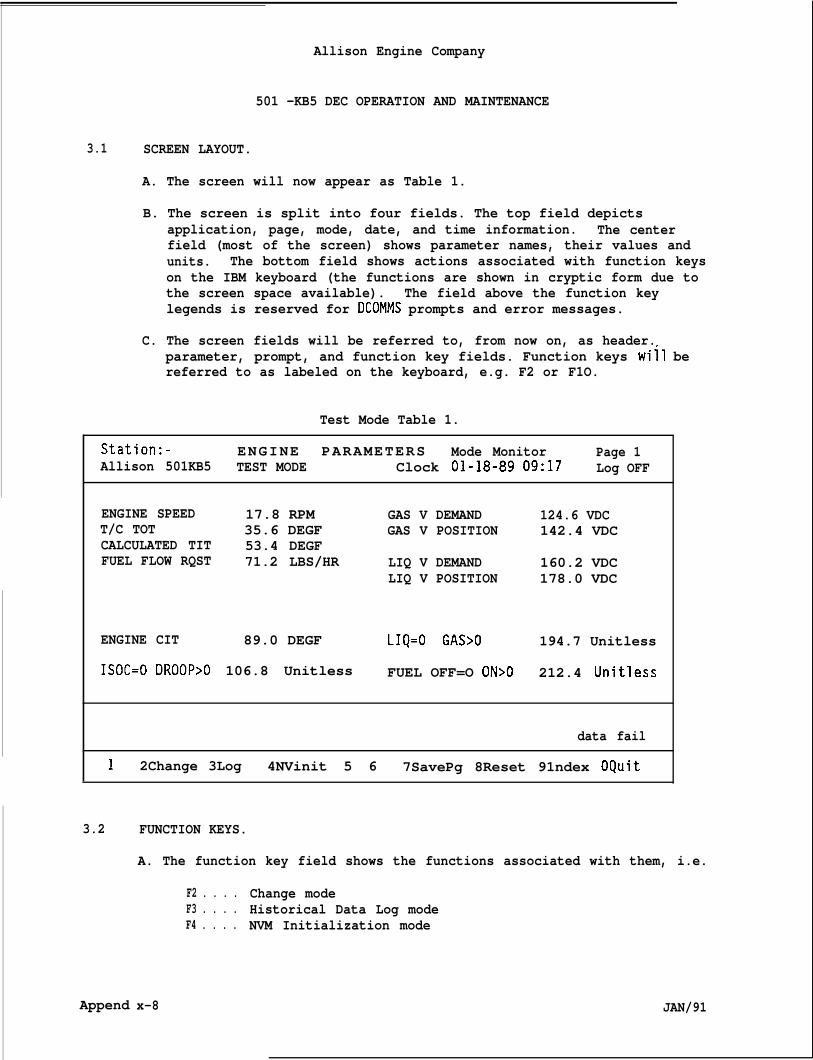
Allison Engine Company
501 -KB5 DEC OPERATION AND MAINTENANCE
3.1 SCREEN LAYOUT.
A. The screen will now appear as Table 1.
B. The screen is split into four fields. The top field depictsapplication, page, mode, date, and time information. The centerfield (most of the screen) shows parameter names, their values andunits. The bottom field shows actions associated with function keyson the IBM keyboard (the functions are shown in cryptic form due tothe screen space available). The field above the function keylegends is reserved for DCOMMS prompts and error messages.
C. The screen fields will be referred to, from now on, as header.parameter, prompt, and function key fields. Function keys will bereferred to as labeled on the keyboard, e.g. F2 or F1O.
Test Mode Table 1.
Station:- ENGINE PARAMETERS Mode Monitor Page 1Allison 501KB5 TEST MODE Clock O1-18-89 09:17 Log OFF
ENGINE SPEED 17.8 RPM GAS V DEMAND 124.6 VDCT/C TOT 35.6 DEGF GAS V POSITION 142.4 VDCCALCULATED TIT 53.4 DEGFFUEL FLOW RQST 71.2 LBS/HR LIQ V DEMAND 160.2 VDC
LIQ V POSITION 178.0 VDC
ENGINE CIT 89.0 DEGF LIQ=O GAS>O 194.7 Unitless
ISOC=O DROOP>O 106.8 Unitless FUEL OFF=O ON>O 212.4 Unitless
data fail
1 2Change 3Log 4NVinit 5 6 7SavePg 8Reset 91ndex OQuit
3.2
Append
FUNCTION KEYS.
A. The function key field shows the functions associated with them, i.e.
F2 . . . . Change modeF3 . . . . Historical Data Log modeF4 . . . . NVM Initialization mode
x-8 JAN/91
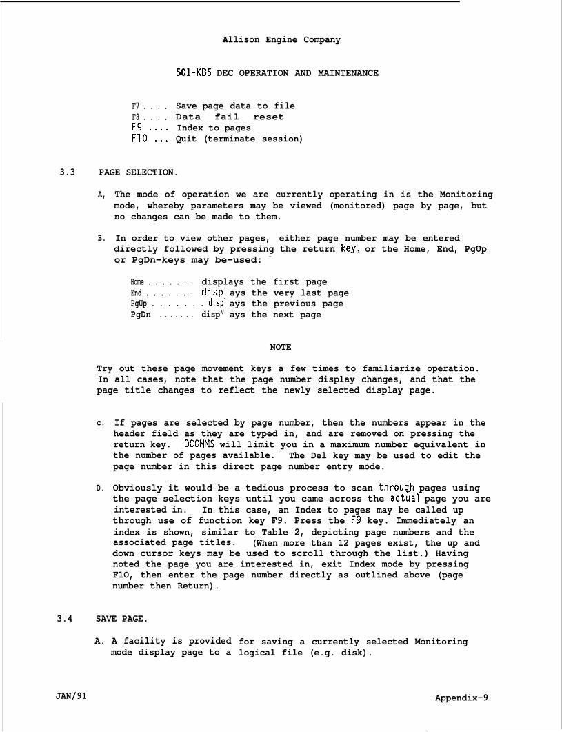
3.3
3.4
JAN/91
F7 . . . .F8 . . . .
;?0”:::
Allison Engine Company
501-KB5 DEC OPERATION AND MAINTENANCE
Save page data to fileData fail resetIndex to pagesQuit (terminate session)
PAGE SELECTION.
A,
B.
The mode of operation we are currently operating in is the Monitoringmode, whereby parameters may be viewed (monitored) page by page, butno changes can be made to them.
In order to view other pages, either page number may be entereddirectly followed by pressing the return key, or the Home, End, PgUpor PgDn-keys may be-used: -
- .
Home . . . . . . . displays the first pageEnd . . . . . . . disp”PgUp . . . . . . . disp”PgDn . . . . . . . disp”
ays the very last pageays the previous pageays the next page
NOTE
Try out these page movement keys a few times to familiarize operation.In all cases, note that the page number display changes, and that thepage title changes to reflect the newly selected display page.
c.
D.
If pages are selected by page number, then the numbers appear in theheader field as they are typed in, and are removed on pressing thereturn key. DCOMMS will limit you in a maximum number equivalent inthe number of pages available. The Del key may be used to edit thepage number in this direct page number entry mode.
Obviously it would be a tedious process to scan throuah pages usingthe page selection keys until you came across the act~al page you areinterested in. In this case, an Index to pages may be called upthrough use of function key F9. Press the F9 key. Immediately anindex is shown, similar to Table 2, depicting page numbers and theassociated page titles. (When more than 12 pages exist, the up anddown cursor keys may be used to scroll through the list.) Havingnoted the page you are interested in, exit Index mode by pressingF1O, then enter the page number directly as outlined above (pagenumber then Return).
SAVE PAGE.
A. A facility is providedmode display page to a
for saving a currently selected Monitoringlogical file (e.g. disk).
Appendix-9
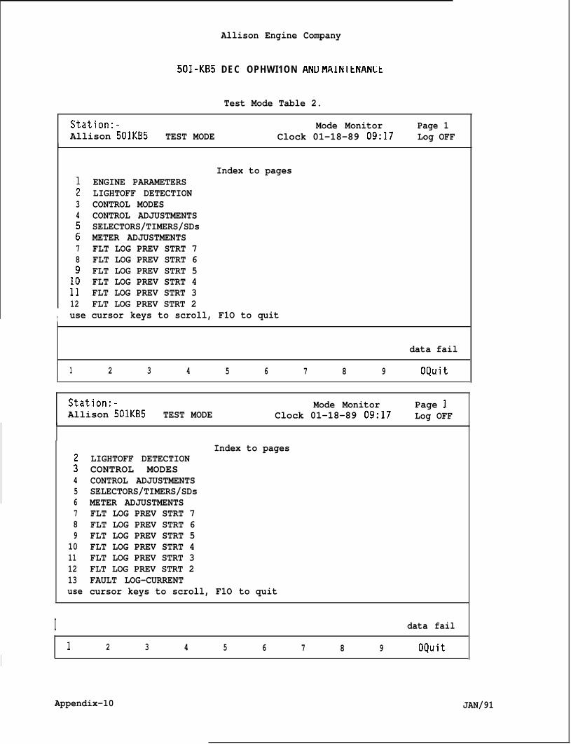
I
Allison Engine Company
501-KB5 DEC OPHWI1ON AND MAINltNANLt
Test Mode Table 2.
Station:- Mode Monitor Page 1Allison 501KB5 TEST MODE Clock 01-18-89 09:17 Log OFF
;34
278
1?1112
Index to pagesENGINE PARAMETERSLIGHTOFF DETECTIONCONTROL MODESCONTROL ADJUSTMENTSSELECTORS/TIMERS/SDsMETER ADJUSTMENTSFLT LOG PREV STRT 7FLT LOG PREV STRT 6FLT LOG PREV STRT 5FLT LOG PREV STRT 4FLT LOG PREV STRT 3FLT LOG PREV STRT 2
I use cursor keys to scroll, F1O to quit
data fail
1 2 3 4 5 6 7 8 9 OQuit
Station:- Mode Monitor Page 1Allison 501KB5 TEST MODE Clock 01-18-89 09:17 Log OFF
:456789
10111213use
Index to pagesLIGHTOFF DETECTIONCONTROL MODESCONTROL ADJUSTMENTSSELECTORS/TIMERS/SDsMETER ADJUSTMENTSFLT LOG PREV STRT 7FLT LOG PREV STRT 6FLT LOG PREV STRT 5FLT LOG PREV STRT 4FLT LOG PREV STRT 3FLT LOG PREV STRT 2FAULT LOG-CURRENTcursor keys to scroll, F1O to quit
I data fail
1 2 3 4 5 6 7 8 9 OQuit
Appendix-10 JAN/91
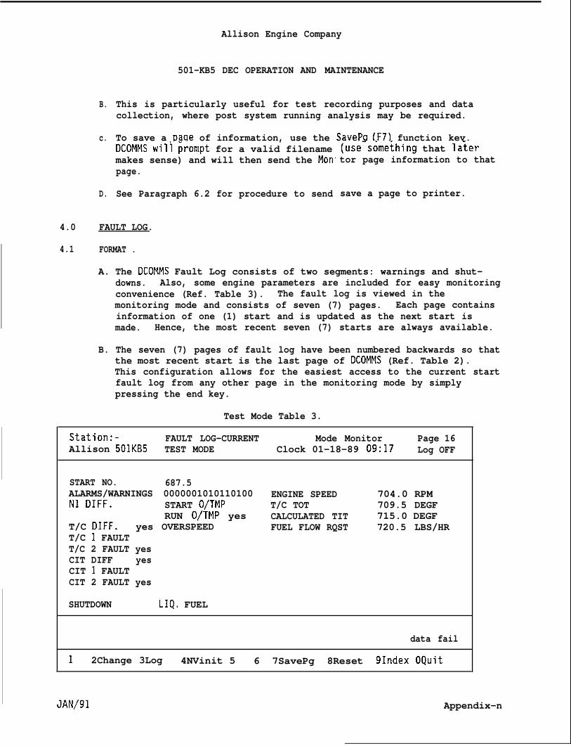
B.
c.
D.
Allison Engine Company
501-KB5 DEC OPERATION AND MAINTENANCE
This is particularly useful for test recording purposes and datacollection, where post system running analysis may be required.
To save a Daae of information, use the SavePQ (F7) function kev.DCOMMS wili ~rompt for a valid filenamemakes sense) and will then send the Mon.page.
See Paragraph 6.2 for procedure to send
(use-some~hing that la;ertor page information to that
save a page to printer.
4.0 FAULT LOG.
4.1 FORMAT .
A. The DCOMMS Fault Log consists of two segments: warnings and shut-downs. Also, some engine parameters are included for easy monitoringconvenience (Ref. Table 3). The fault log is viewed in themonitoring mode and consists of seven (7) pages. Each page containsinformation of one (1) start and is updated as the next start ismade. Hence, the most recent seven (7) starts are always available.
B. The seven (7) pages of fault log have been numbered backwards so thatthe most recent start is the last page of DCOMMS (Ref. Table 2).This configuration allows for the easiest access to the current startfault log from any other page in the monitoring mode by simplypressing the end key.
Test Mode Table 3.
Station:- FAULT LOG-CURRENT Mode Monitor Page 16Allison 501KB5 TEST MODE Clock 01-18-89 09:17 Log OFF
START NO. 687.5ALARMS/WARNINGS 0000001010110100 ENGINE SPEED 704.0 RPMN1 DIFF. START O/TMP T/C TOT 709.5 DEGF
RUN O/TMP yes CALCULATED TIT 715.0 DEGFT/C DIFF. yes OVERSPEED FUEL FLOW RQST 720.5 LBS/HRT/C 1 FAULTT/C 2 FAULT yesCIT DIFF yesCIT 1 FAULTCIT 2 FAULT yes
SHUTDOWN LIQ, FUEL
data fail
1 2Change 3Log 4NVinit 5 6 7SavePg 8Reset 91ndex OQuit
.JAN/91 Appendix-n
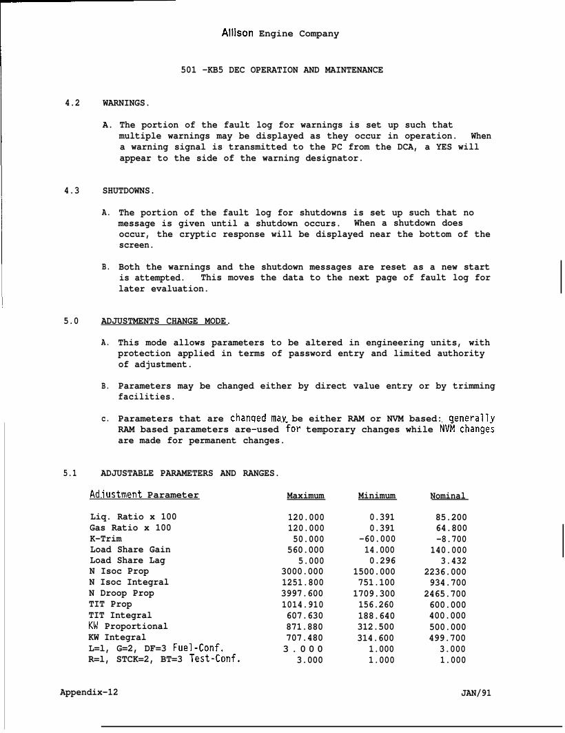
Aliison Engine Company
501 -KB5 DEC OPERATION AND MAINTENANCE
4.2 WARNINGS.
A. The portion of the fault log for warnings is set up such thatmultiple warnings may be displayed as they occur in operation. Whena warning signal is transmitted to the PC from the DCA, a YES willappear to the side of the warning designator.
4.3 SHUTDOWNS.
A.
B.
The portion of the fault log for shutdowns is set up such that nomessage is given until a shutdown occurs. When a shutdown doesoccur, the cryptic response will be displayed near the bottom of thescreen.
Both the warnings and the shutdown messages are reset as a new startis attempted. This moves the data to the next page of fault log forlater evaluation.
5.0 ADJUSTMENTS CHANGE MODE.
A.
B.
c.
This mode allows parameters to be altered in engineering units, withprotection applied in terms of password entry and limited authorityof adjustment.
Parameters may be changed either by direct value entry or by trimmingfacilities.
Parameters that are chanqed may be either RAM or NVM based: aenerallvRAM based parameters are-used ~or temporary changes while NVfi change:are made for permanent changes.
5.1 ADJUSTABLE PARAMETERS AND RANGES.
Ad.iustment Parameter
Liq. Ratio x 100Gas Ratio x 100K-TrimLoad Share GainLoad Share LagN Isoc PropN Isoc IntegralN Droop PropTIT PropTIT IntegralKW ProportionalKW IntegralL=l, G=2, DF=3 Fuel-Conf.R=l, STCK=2, BT=3 Test-Conf.
Appendix-12
Maximum
120.000120.00050.000
560.0005.000
3000.0001251.8003997.6001014.910607.630871.880707.4803 . 0 0 0
3.000
Minimum
0.3910.391
-60.00014.0000.296
1500.000751.1001709.300156.260188.640312.500314.600
1.0001.000
Nominal
85.20064.800-8.700
140.0003.432
2236.000934.700
2465.700600.000400.000500.000499.700
3.0001.000
JAN/91
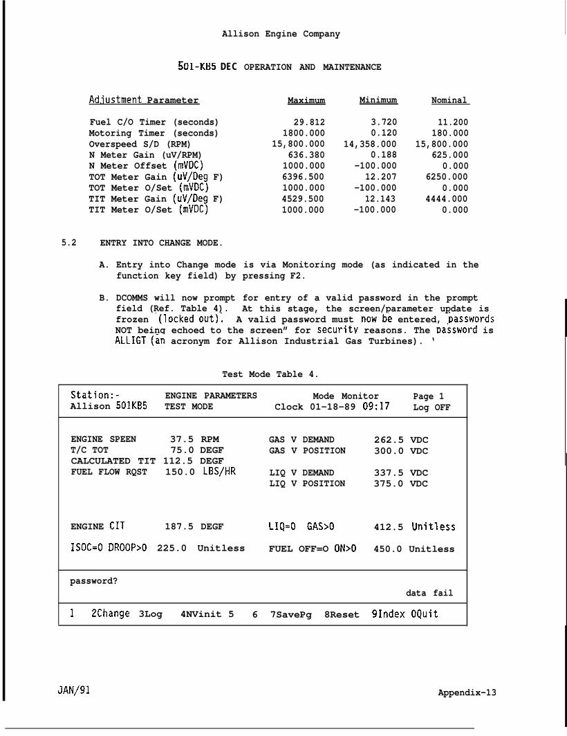
Allison Engine Company
!iO1-K135 DEC OPERATION AND MAINTENANCE
Ad.iustment Parameter
Fuel C/O Timer (seconds)Motoring Timer (seconds)Overspeed S/D (RPM)N Meter Gain (uV/RPM)N Meter Offset (mVDC)TOT Meter Gain (uV/Deg F)TOT Meter O/Set (mVDC)TIT Meter Gain (uV/Deg F)TIT Meter O/Set (mVDC)
5.2 ENTRY INTO CHANGE MODE.
A. Entry into Change modefunction key field) by
B. DCOMMS will now promptfield (Ref. Table 4).
Maximum
29.8121800.000
15,800.000636.3801000.0006396.5001000.0004529.5001000.000
Minimum
3.7200.120
14,358.0000.188
-100.00012.207
-100.00012.143
-100.000
Nominal
11.200180.000
15,800.000625.000
0.0006250.000
0.0004444.000
0.000
is via Monitoring mode (as indicated in thepressing F2.
for entry of a valid password in the promptAt this stage, the screen/parameter update is
frozen ”(locked out); A valid password must nowbe entered, basswordsNOT being echoed to the screen” for securit.v reasons. The Dassword isALLIGT (in acronym for Allison Industrial Gas Turbines). ‘
Test Mode Table 4.
Station:- ENGINE PARAMETERS Mode Monitor Page 1Allison 501KB5 TEST MODE Clock 01-18-89 09:17 Log OFF
ENGINE SPEEN 37.5 RPM GAS V DEMAND 262.5 VDCT/C TOT 75.0 DEGF GAS V POSITION 300.0 VDCCALCULATED TIT 112.5 DEGFFUEL FLOW RQST 150.0 LBS/HR LIQ V DEMAND 337.5 VDC
LIQ V POSITION 375.0 VDC
ENGINE CIT 187.5 DEGF LIQ=O GAS>O 412.5 Unitless
ISOC=O DROOP>O 225.0 Unitless FUEL OFF=O ON>O 450.0 Unitless
password?data fail
1 2Change 3Log 4NVinit 5 6 7SavePg 8Reset 91ndex OQuit
.dAN/91 Appendix-13
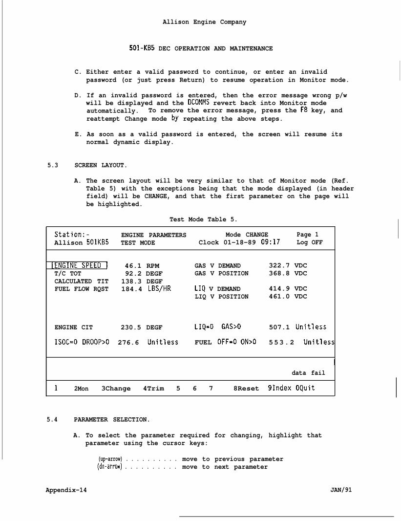
Allison Engine Company
501-KB5 DEC OPERATION AND MAINTENANCE
C. Either enter a valid password to continue, or enter an invalidpassword (or just press Return) to resume operation in Monitor mode.
D. If an invalid password is entered, then the error message wrong p/wwill be displayed and the DCOMMS revert back into Monitor modeautomatically. To remove the error message, press the F8 key, andreattempt Change mode by repeating the above steps.
E. As soon as a valid password is entered, the screen will resume itsnormal dynamic display.
5.3 SCREEN LAYOUT.
A. The screen layout will be very similar to that of Monitor mode (Ref.Table 5) with the exceptions being that the mode displayed (in headerfield) will be CHANGE, and that the first parameter on the page willbe highlighted.
Test Mode Table 5.
Station:- ENGINE PARAMETERS Mode CHANGE Page 1Allison 501KB5 TEST MODE Clock 01-18-89 09:17 Log OFF
~ENGINE SPEED I 46.1 RPM GAS V DEMAND 322.7 VDCT/C TOT 92.2 DEGF GAS V POSITION 368.8 VDCCALCULATED TIT 138.3 DEGFFUEL FLOW RQST 184.4 LBS/HR LIQ V DEMAND 414.9 VDC
LIQ V POSITION 461.0 VDC
ENGINE CIT 230.5 DEGF LIQ=O GAS>O 507.1 Unitless
ISOC=O DROOP>O 276.6 Unitless FUEL OFF=O ON>O 553.2 Unitless
~data fail
1 2Mon 3Change 4Trim 5 6 7 8Reset 91ndex OQuit
5.4 PARAMETER SELECTION.
A. To select the parameter required for changing, highlight thatparameter using the cursor keys:
(up-arrow) . . . . . . . . . . move to previous parameter(dn-arrow) . . . . . . . . . . move to next parameter
Appendix-14 JAN/91
B.
c.
D.
E.
Allison Engine Company
501-KB5 DEC OPERATION AND MAINTENANCE
(left-arrow) . . . . . . . . move to first parameter in page(right-arrow) . . . . . . . move to last parameter in page
If the required parameter is not displayed on the current page, thenselect the required page either by using the page select keys or bydirect page number entry.
The page index is available in this mode via the F9 key as describedin Par=graph 3.3.
Use the page selection keys and the cursor control keys tofamiliarize yourself with operation.
On determining the parameter YOU want tothen a change-may be applied either by dvia the following procedure.
5.5 DIRECT VALUE ENTRY.
A.
B.
c.
D.
E.
F.
change, and highlighting t,ng
With the required parameter highlighted,
irect-value entry oi trirnm
press the F3 key. Theparameter name and-value will now be transferred into the promptfield, and the associated NVM (default value) will also bedisplayed. In test mode, the statement:
NVM
will be derror has
value = ????
splayed, as DIGICON is not on-line, and a communicationbeen detected., ignore this.
The screen and parameter update will now be frozen,data entry for the parameter from the keyboard.
Enter a valid data value at the prompt, in engineerentering the units name, i.e., enter a valid decima”terminating with pressing Return.
awaiting a valid
ng units, withoutvalue
Should a valid data value be entered, DCOMMS will now prompt you forRAM, NVM, or both RAM and NVM update (Ref. Table 6). Press the keyassociated with your selection (R, N, or B). Selecting R will updateRAM based values only, N will update NVM base values only while Bwill update both RAM and NVM based values simultaneously.
If either R or B is selected from above, then the IBM internaldatabase will be updated together with the displayed screen value, ifN is selected then the associated IBM internal default database ismodified but not the screen displayed value (as the displayedparameters are RAM based).
DCOMMS will revert back to a dynamic display, and remain in Changemode allowing further changes to be made as required. Experiment afew times to familiarize yourself.
JAN/91 Appendix-15
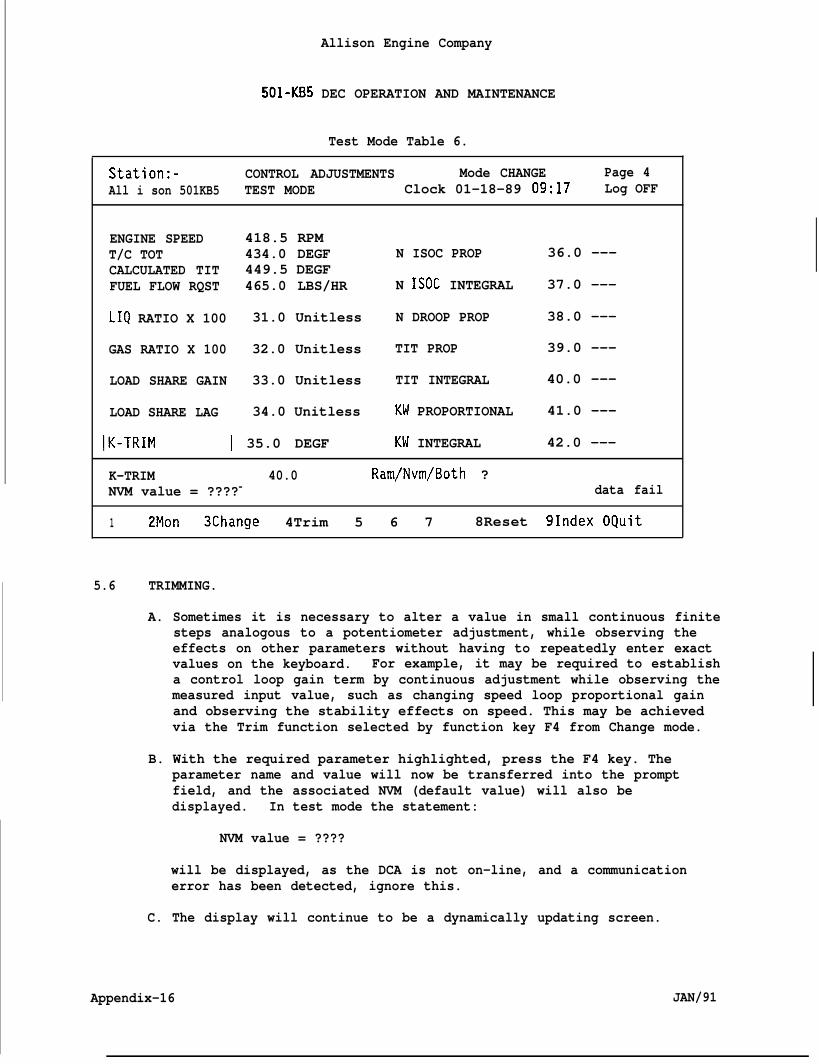
Allison Engine Company
501-KB5 DEC OPERATION AND MAINTENANCE
Test Mode Table 6.
Station:- CONTROL ADJUSTMENTS Mode CHANGE Page 4All i son 501KB5 TEST MODE Clock 01-18-89 09:17 Log OFF
ENGINE SPEED 418.5 RPMT/C TOT 434.0 DEGF N ISOC PROP 36.0 ---CALCULATED TIT 449.5 DEGFFUEL FLOW RQST 465.0 LBS/HR N ISOC INTEGRAL 37.0 ---
LIQ RATIO X 100 31.0 Unitless N DROOP PROP 38.0 ---
GAS RATIO X 100 32.0 Unitless TIT PROP 39.0 ---
LOAD SHARE GAIN 33.0 Unitless TIT INTEGRAL 40.0 ---
LOAD SHARE LAG 34.0 Unitless KW PROPORTIONAL 41.0 ---
IK-TRIM I 35.0 DEGF KW INTEGRAL 42.0 ---
K-TRIM 40.0 Ram/Nvm/Both ?NVM value = ????= data fail
1 2Mon 3Change 4Trim 5 6 7 8Reset 91ndex OQuit
5.6 TRIMMING.
A. Sometimes it is necessary to alter a value in small continuous finitesteps analogous to a potentiometer adjustment, while observing theeffects on other parameters without having to repeatedly enter exactvalues on the keyboard. For example, it may be required to establisha control loop gain term by continuous adjustment while observing themeasured input value, such as changing speed loop proportional gainand observing the stability effects on speed. This may be achievedvia the Trim function selected by function key F4 from Change mode.
B. With the required parameter highlighted, press the F4 key. Theparameter name and value will now be transferred into the promptfield, and the associated NVM (default value) will also bedisplayed. In test mode the statement:
NVM value = ????
will be displayed, as the DCA is not on-line, and a communicationerror has been detected, ignore this.
C. The display will continue to be a dynamically updating screen.
Appendix-16 JAN/91
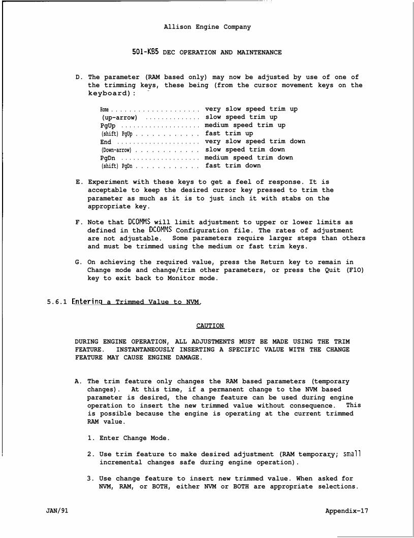
Allison Engine Company
501-KB5 DEC OPERATION AND MAINTENANCE
D. The parameter (RAM based only) may now be adjusted by use of one ofthe trimming keys, these being (from the cursor movement keys on thekeyboard): -
Home . . . . . . . . . . . . . . . . . . . .(up-arrow) . . . . . . . . . . . . . .PgUp . . . . . . . . . . . . . . . . . . . .(shift) PgUp . . . . . . . . . . . .End . . . . . . . . . . . . . . . . . . . . .(Down-arrow) . . . . . . . . . . . .PgDn . . . . . . . . . . . . . . . . . . . .(shift) PgDn . . . . . . . . . . . .
very slow speed trim upslow speed trim upmedium speed trim upfast trim upvery slow speed trim downslow speed trim downmedium speed trim downfast trim down
E. Experiment with these keys to get a feel of response. It isacceptable to keep the desired cursor key pressed to trim theparameter as much as it is to just inch it with stabs on theappropriate key.
F. Note that DCOMMS will limit adjustment to upper or lower limits asdefined in the DCOMMS Configuration file. The rates of adjustmentare not adjustable. Some parameters require larger steps than othersand must be trimmed using the medium or fast trim keys.
G. On achieving the required value, press the Return key to remain inChange mode and change/trim other parameters, or press the Quit (F1O)key to exit back to Monitor mode.
5.6.1 Enterinq a Trimmed Value to NVM.
CAUTION
DURING ENGINE OPERATION, ALL ADJUSTMENTS MUST BE MADE USING THE TRIMFEATURE. INSTANTANEOUSLY INSERTING A SPECIFIC VALUE WITH THE CHANGEFEATURE MAY CAUSE ENGINE DAMAGE.
A. The trim feature only changes the RAM based parameters (temporarychanges). At this time, if a permanent change to the NVM basedparameter is desired, the change feature can be used during engineoperation to insert the new trimmed value without consequence. Thisis possible because the engine is operating at the current trimmedRAM value.
1. Enter Change Mode.
2. Use trim feature to make desired adjustment (RAM temporary; smallincremental changes safe during engine operation).
3. Use change feature to insert new trimmed value. WhenNVM, RAM, or BOTH, either NVM or BOTH are appropriate
JAN/91
-
asked forselections.
Appendix-17
Allison Engine Company
501 -KB5 DEC OPERATION AND MAINTENANCE
4. Verify that the NVM value now matches the RAM value. Use thechange feature again and compare the value in the parameter field(RAM) with that in the prompt field (NVM). If they match, simplypush return; if they do not, try the procedure again.
5. Continue with other adjustments or exit Change Mode.
5.7 ERROR MESSAGES.
A. It may become apparent through experimentation that several differenttypes of error messages can be displayed, these being described asfollows.
5.7.1 Wronq Password.
A. This message is dkeyboard. At the
splayed if an incorrect password is entered at thesame time DCOMMS will revert back to Monitor mode.
B. To remove the error message, press the Reset (F8) key, and ifdesired, repeat the required operation.
5.7.2 Guarded Access.
A.
B.
This message will be displayed if unauthorized access (to change) isattempted on a parameter. This may occur if, for example, operatoraccess is attempted on a parameter that has been defined as amonitoring only within the DCOMMS configuration file, or if anattempt has been made (at any level) to change the value of aparameter defined as a status/flag parameter. Operator access isrestricted solely to parameters defined as adjustable setpoints.
To remove the error message, press the Reset (F8) key, and if desiredrepeat the required operation”.
5.7.3 Ranqe Error.
A. This message will be displayed if an attempt has been made to alter avalue out of prescribed limits (as defined in the DCOMMS configura-tion file).
B. The selected parameter value will not be altered.
C. To remove the error message, press the Reset (F8) key and if desired,repeat the required operation.
Appendix-18 JAN/91
Allison Engine Company
501-KB5 DEC OPERATION AND MAINTENANCE
5.8 ABORT AND CANCEL FUNCTIONS .
A. If at any time during the Change mode you wantMonitoring mode, then either press the Quit (F”mode (F2) key.
5.9 CAUTIONS.
to quit back toO) key or the Monitor
A. It is not wise to leave the system unattended while operating inChange mode as it would be possible for unauthorized changes to bemade. Until Monitor mode is reestablished, the system remains in anunlocked state, as password entry is required only to change mode,not for each and every discrete alteration.
6.0 DATA RECORDING LOG MODE.
A.
B.
c.
D.
E.
F.
JAN/91
This mode allows selected parameters to be logged at discrete timeintervals, with associated data being saved to an external medium(e.g., disk file or printer) for later analysis or for informationrecording reasons.
Up to 8 parameters may be selected for logging at any one time, theseparameters being independent of screen and parameter layout. Thelogging function is performed within DCOMMS during Monitor modeoperation, such that parameters may be displayed on one screen pagewhile parameters from that and/or other pages may be logged at thesame time.
Parameters are logged as records, where a record is one block ofparameter information as selected. Up to a limit of 1000 records maybe selected for logging, thus if 8 parameters and 1000 records areselected, then a total of 1000 lines of data associated with 8parameters will be logged.
The data logged is time tagged, per record, in units of hours,minutes and seconds.
The resolution of data logging largely depends on the speed/power ofthe IBM (or compatible) personal computer system used, as well as thenumber of parameters being displayed on a Monitoring mode displaypage (as the communication process to the DCA and subsequent dataconversion/display processes are increased, due to the fact that bothMonitoring and Logging functions are interleaved within DCOMMS).However, generally the minimum update time may be of the order of 1second for XT compatible com~uters and 0.5 seconds for ATcompatibles. ‘
The data logging function w“have been logged, or may bedemand.
11 terminate naturally after all recordsterminated prematurely by operator
Appendix-19
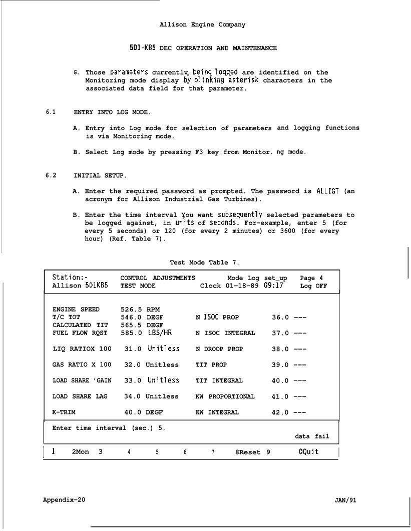
G.
Allison Engine Company
501-KB5 DEC OPERATION AND MAINTENANCE
Those ~arameters currently beinq loqqed are identified on theMonitoring mode display b~ blinking-~sterisk characters in theassociated data field for that parameter.
6.1 ENTRY INTO LOG MODE.
A. Entry into Log mode for selection of parametersis via Monitoring mode.
B. Select Log mode by pressing F3 key from Monitor.
6.2 INITIAL SETUP.
and logging functions
ng mode.
A. Enter the required password as prompted. The password is ALLIGT (anacronym for Allison Industrial Gas Turbines).
B. Enter the time interval You want subseauentl.y selected parameters tobe logged against, in units of seconds: For-example, enter 5 (forevery 5 seconds) or 120 (for every 2 minutes) or 3600 (for everyhour) (Ref. Table 7).
Test Mode Table 7.
Station:- CONTROL ADJUSTMENTS Mode Log set_up Page 4Allison 501KB5 TEST MODE Clock 01-18-89 09:17 Log OFF
ENGINE SPEED 526.5 RPMT/C TOT 546.0 DEGF N ISOC PROP 36.0 ---CALCULATED TIT 565.5 DEGFFUEL FLOW RQST 585.0 LBS/HR N ISOC INTEGRAL 37.0 ---
LIQ RATIOX 100 31.0 Unitless N DROOP PROP 38.0 ---
GAS RATIO X 100 32.0 Unitless TIT PROP 39.0 ---
LOAD SHARE ’GAIN 33.0 Unitless TIT INTEGRAL 40.0 ---
LOAD SHARE LAG 34.0 Unitless KW PROPORTIONAL 41.0 ---
K-TRIM 40.0 DEGF KW INTEGRAL 42.0 ---
Enter time interval (sec.) 5.data fail
I 1 2Mon 3 4 5 6 7 8Reset 9 OQuit I
Appendix-20 JAN/91
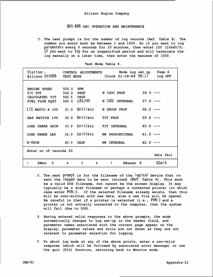
Allison Engine Company
501-KB5 DEC OPERATION AND MAINTENANCE
C. The next prompt is for the number of log records (Ref. Table 8). Thenumber you enter must be between 1 and 1000. So if you want to logt)arameters everv 5 seconds for 10 minutes, then enter 120 (10x60/5).~f”you want to log for an unspecified period and will terminate thelog manually at a later time, then enter the maximum of 1000.
Test Mode Table 8.
Station:- CONTROL ADJUSTMENTS Mode Log set_up Page 4Allison 501KB5 TEST MODE Clock 01-18-89 09:17 Log OFF
ENGINE SPEEDT/C TOTCALCULATED TITFUEL FLOW RQST
LIQ RATIO X 100
GAS RATIOX 100
LOAD SHARE GAIN
LOAD SHARE LAG
K-TRIM
526.5546.0565.5585.0
31.0
32.0
33.0
34.0
40.0
RPMDEGF N ISOC PROP 36.0 ---DEGFLBS/HR N ISOC INTEGRAL 37.0 ---
Unitless N DROOP PROP 38.0 ---
Unitless TIT PROP 39.0 ---
Unitless TIT INTEGRAL 40.0 ---
Unitless KW PROPORTIONAL 41.0 ---
DEGF KW INTEGRAL 42.0 ---
Enter no of records 20data fail
1 2Mon 3 4 5 6 7 8Reset 9 OQuit
D.
E.
F.
JAN/91
The next DromDt is for the filename of the lociical device that YOUwant the iogged data to be sent (stored) (Ref~ Table 9). This mustbe a valid DOS filename, but cannot be the screen display. It maytypically be a disk filename or perhaps a connected printer (in whichcase enter PRN:). If the selected filename already exists, then thiswill be over-written with new data, else a new file will be opened.Be careful in that if a printer is selected (i.e., PRN:) and aprinter is not actually connected to the computer, then the systemwill fail (due to DOS).
Having entered valid responses to the above prompts, the modeautomatically changes to Log set-up in the header field, andparameter names associated with the current page appear on thedisplay; parameter values and units are not shown as they are notrelevant to parameter selection for logging.
To abort log mode at any of the above points, enter a non-validresponse (which will be followed by associated error message) or usethe quit (F1O) function, returning back to Monitor mode.
Appendix-21
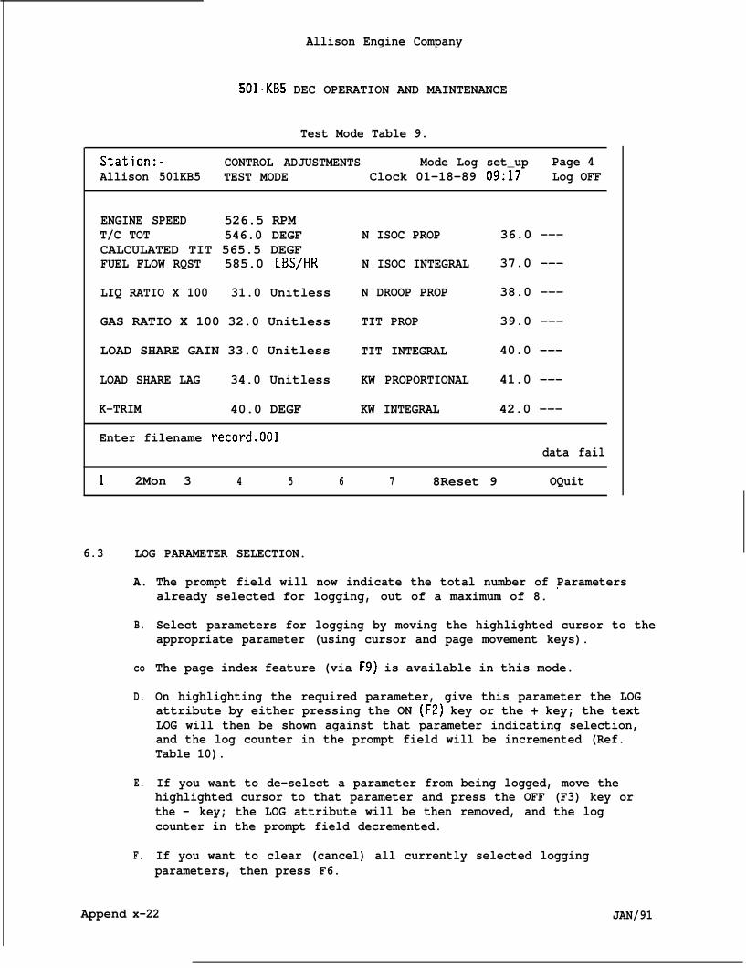
Allison Engine Company
501-KB5 DEC OPERATION AND MAINTENANCE
Test Mode Table 9.
Station:- CONTROL ADJUSTMENTS Mode Log set_up Page 4Allison 501KB5 TEST MODE Clock 01-18-89 09:17 Log OFF
ENGINE SPEED 526.5 RPMT/C TOT 546.0 DEGF N ISOC PROP 36.0 ---CALCULATED TIT 565.5 DEGFFUEL FLOW RQST 585.0 LBS/HR N ISOC INTEGRAL 37.0 ---
LIQ RATIO X 100 31.0 Unitless N DROOP PROP 38.0 ---
GAS RATIO X 100 32.0 Unitless TIT PROP 39.0 ---
LOAD SHARE GAIN 33.0 Unitless TIT INTEGRAL 40.0 ---
LOAD SHARE LAG 34.0 Unitless KW PROPORTIONAL 41.0 ---
K-TRIM 40.0 DEGF KW INTEGRAL 42.0 ---
Enter filename record.001data fail
1 2Mon 3 4 5 6 7 8Reset 9 OQuit
6.3
Append
LOG PARAMETER SELECTION.
A. The prompt field will now indicate the total number of Parameters
B.
co
D.
E.
F.
already selected for logging, out of a maximum of 8. 0
Select parameters for logging by moving the highlighted cursor to theappropriate parameter (using cursor and page movement keys).
The page index feature (via F9) is available in this mode.
On highlighting the required parameter, give this parameter the LOGattribute by either pressing the ON (F2) key or the + key; the textLOG will then be shown against that parameter indicating selection,and the log counter in the prompt field will be incremented (Ref.Table 10).
If you want to de-select a parameter from being logged, move thehighlighted cursor to that parameter and press the OFF (F3) key orthe - key; the LOG attribute will be then removed, and the logcounter in the prompt field decremented.
If you want to clear (cancel) all currently selected loggingparameters, then press F6.
x-22 JAN/91
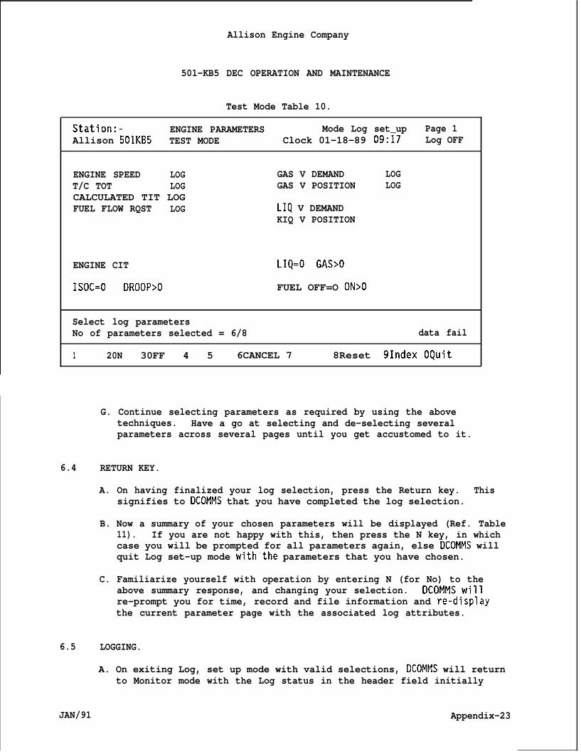
Allison Engine Company
501-KB5 DEC OPERATION AND MAINTENANCE
Test Mode Table 10.
Station:- ENGINE PARAMETERS Mode Log set_up Page 1Allison 501KB5 TEST MODE Clock 01-18-89 09:17 Log OFF
ENGINE SPEED LOG GAS V DEMAND LOGT/C TOT LOG GAS V POSITION LOGCALCULATED TIT LOGFUEL FLOW RQST LOG LIQ V DEMAND
KIQ V POSITION
ENGINE CIT LIQ=O GAS>O
ISOC=O DROOP>O FUEL OFF=O ON>O
Select log parametersNo of parameters selected = 6/8 data fail
1 20N 30FF 4 5 6CANCEL 7 8Reset 91ndex OQuit
G. Continue selecting parameters as required by using the abovetechniques. Have a go at selecting and de-selecting severalparameters across several pages until you get accustomed to it.
6.4 RETURN KEY.
A. On having finalized your log selection, press the Return key.signifies to DCOMMS that you have completed the log selection.
This
B. Now a summary of your chosen parameters will be displayed (Ref. Table11). If you are not happy with this, then press the N key, in whichcase you will be prompted for all parameters again, else DCOMMS willquit Log set-up mode with”the parameters that you have chosen.
C. Familiarize yourself with operation by entering N (for No) to theabove summary response, and changing your selection. DCOMMS willre-prompt you for time, record and file information and re-displaythe current parameter page with the associated log attributes.
6.5 LOGGING.
A. On exiting Log, set up mode with valid selections, DCOMMS will returnto Monitor mode with the Log status in the header field initially
JAN/91 Appendix-23
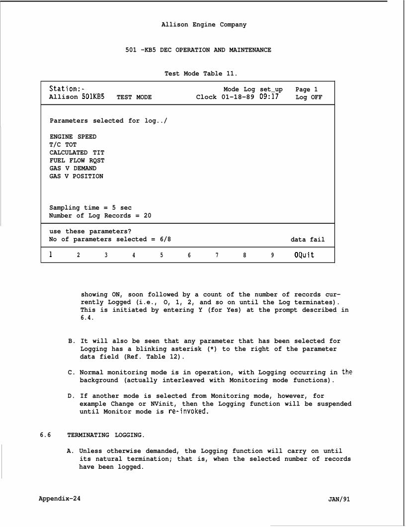
Allison Engine Company
501 -KB5 DEC OPERATION AND MAINTENANCE
Test Mode Table 11.
Station:- Mode Log set_up Page 1Allison 501KB5 TEST MODE Clock 01-18-89 09:17 Log OFF
Parameters selected for log../
ENGINE SPEEDT/C TOTCALCULATED TITFUEL FLOW RQSTGAS V DEMANDGAS V POSITION
Sampling time = 5 secNumber of Log Records = 20
use these parameters?No of parameters selected = 6/8 data fail
1 2 3 4 5 6 7 8 9 OQuit
showing ON, soon followed by a count of the number of records cur-rently Logged (i.e., O, 1, 2, and so on until the Log terminates).This is initiated by entering Y (for Yes) at the prompt described in6.4.
B. It will also be seen that any parameter that has been selected forLogging has a blinking asterisk (*) to the right of the parameterdata field (Ref. Table 12).
C. Normal monitoring mode is in operation, with Logging occurring in thebackground (actually interleaved with Monitoring mode functions).
D. If another mode is selected from Monitoring mode, however, forexample Change or NVinit, then the Logging function will be suspendeduntil Monitor mode is re-invoked.
6.6 TERMINATING LOGGING.
A. Unless otherwise demanded, the Logging function will carry on untilits natural termination; that is, when the selected number of recordshave been logged.
Appendix-24 JAN/91
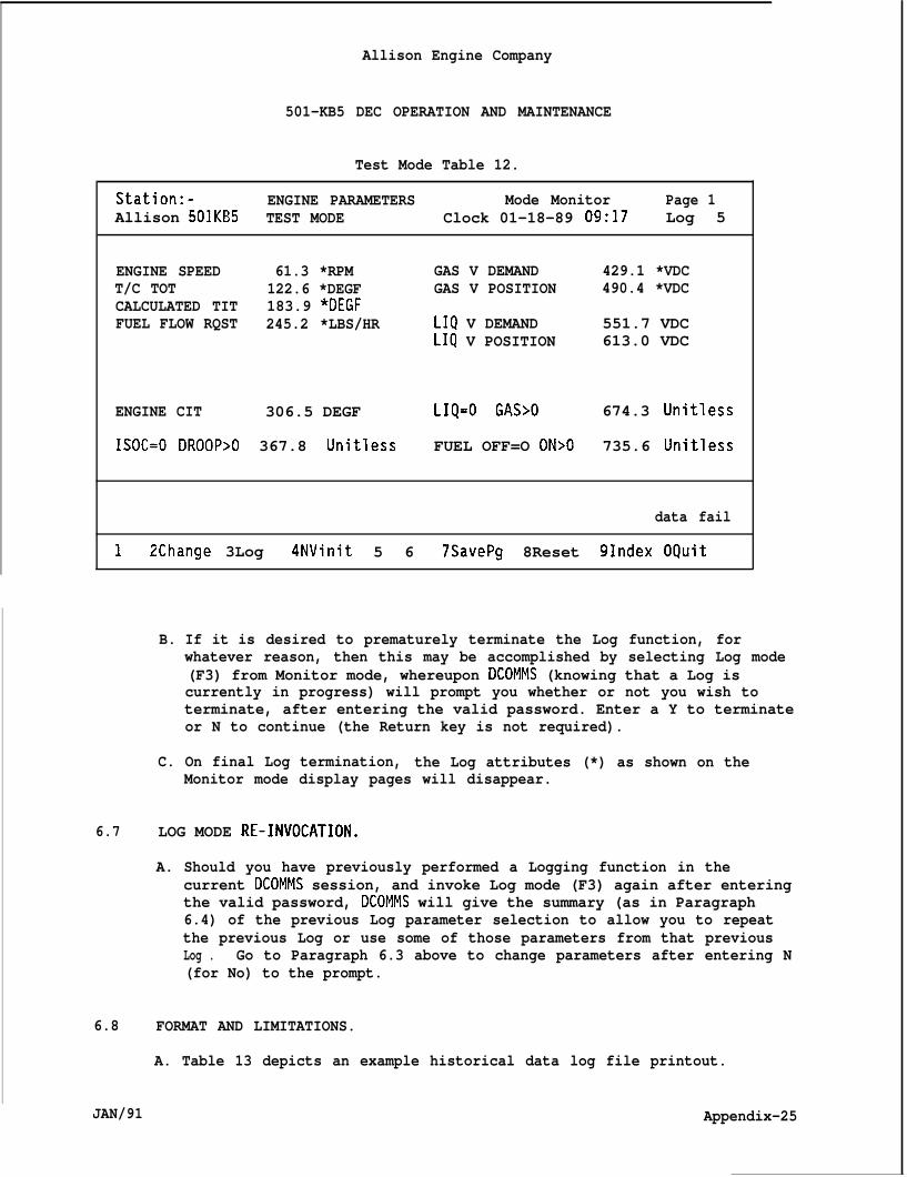
Allison Engine Company
501-KB5 DEC OPERATION AND MAINTENANCE
Test Mode Table 12.
Station:- ENGINE PARAMETERS Mode Monitor Page 1Allison 501KB5 TEST MODE Clock 01-18-89 09:17 Log 5
ENGINE SPEED 61.3 *RPM GAS V DEMAND 429.1 *VDCT/C TOT 122.6 *DEGF GAS V POSITION 490.4 *VDCCALCULATED TIT 183.9 *DEGFFUEL FLOW RQST 245.2 *LBS/HR LIQ V DEMAND 551.7 VDC
LIQ V POSITION 613.0 VDC
ENGINE CIT 306.5 DEGF LIQ=O GAS>O 674.3 Unitless
ISOC=O DROOP>O 367.8 Unitless FUEL OFF=O ON>O 735.6 Unitless
data fail
1 2Change 3Log 4NVinit 5 6 7SavePg 8Reset 91ndex OQuit
B. If it is desired to prematurely terminate the Log function, forwhatever reason, then this may be accomplished by selecting Log mode(F3) from Monitor mode, whereupon DCOMMS (knowing that a Log iscurrently in progress) will prompt you whether or not you wish toterminate, after entering the valid password. Enter a Y to terminateor N to continue (the Return key is not required).
C. On final Log termination, the Log attributes (*) as shown on theMonitor mode display pages will disappear.
6.7 LOG MODE RE-INVOCATION.
A. Should you have previously performed a Logging function in thecurrent DCOMMS session, and invoke Log mode (F3) again after enteringthe valid password, DCOMMS will give the summary (as in Paragraph6.4) of the previous Log parameter selection to allow you to repeatthe previous Log or use some of those parameters from that previousLog . Go to Paragraph 6.3 above to change parameters after entering N(for No) to the prompt.
6.8 FORMAT AND LIMITATIONS.
A. Table 13 depicts an example historical data log file printout.
JAN/91 Appendix-25
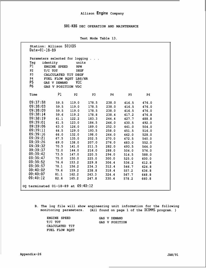
Allison Engine Company
501-KB5 DEC OPERATION AND MAINTENANCE
Test Mode Table 13.
Station: Allison 501KB5Date=O1-18-89
Parameters selected for logging . . .Tag identity unitsP1 ENGINE SPEED RPMP2 T/C TOT DEGFP3 CALCULATED TIT DEGFP4 FUEL FLOW RQST LBS/HR
GAS V DEMAND VDC;: GAS V POSITION VDC
Time PI P2 P3 P4 P5 P6
09:37:58 59.5 119.0 178.5 238.0 416.5 476.009:38:03 59.5 119.0 178.5 238.0 416.5 476.009:38:09 59.5 119.0 178.5 238.0 416.5 476.009:38:14 59.6 119.2 178.8 238.4 417.2 476.809:38:19 61.1 122.2 183.3 244.4 427.7 488.809:39:01 61.5 123.0 184.5 246.0 430.5 492.009:39:06 63.0 126.0 189.0 252.0 441.0 504.009:39:11 64.5 129.0 193.5 258.0 451.5 516.009:39:16 66.0 132.0 198.0 264.0 462.0 528.009:39:21 67.5 135.0 202.5 270.0 472.5 540.009:39:26 69.0 138.0 207.0 276.0 483.0 552.009:39:32 70.5 141.0 211.5 282.0 493.5 564.009:39:37 72.0 144.0 216.0 288.0 504.0 576.009:39:42 73.5 147.0 220.5 294.0 514.5 588.009:39:47 75.0 150.0 225.0 300.0 525.0 600.009:39:52 76.6 153.2 229.8 306.4 536.2 612.809:39:57 78.1 156.2 234.3 312.4 546.7 624.809:40:02 79.6 159.2 238.8 318.4 557.2 636.809:40:07 81.1 162.2 243.3 324.4 567.7 648.809:40:12 82.6 165.2 247.8 330.4 578.2 660.8
og terminated 01-18-89 at 09:40:12
B. The log file will show engineering unit information for the followingmonitoring parameters. (All found on page 1 of the DCOMMS program. )
ENGINE SPEED GAS V DEMANDT/C TOT GAS V POSITIONCALCULATED TITFUEL FLOW RQST
Appendix-26 JAN/91
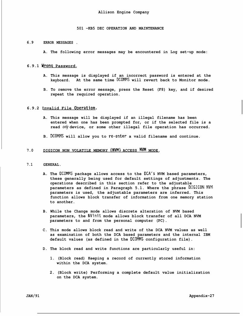
Allison Engine Company
501 -KB5 DEC OPERATION AND MAINTENANCE
6.9 ERROR MESSAGES .
A. The following error messages may be encountered in Log set-up mode:
6.9.1 Wronq Password.
A. This message is displayed if an incorrect password is entered at thekeyboard. At the same time DCOMMS will revert back to Monitor mode.
B. To remove the error message, press the Reset (F8) key, and if desiredrepeat the required operation.
6.9.2 Invalid File O~eration.
A. This message will be displayed if an illegal filename has beenentered when one has been prompted for, or if the selected file is aread only device, or some other illegal file operation has occurred.
B. DCOMMS will allow you to re-enter a valid filename and continue.
7.0 DIGICON NON VOLATILE MEMORY (NVM) ACCESS NVM MODE.
7.1 GENERAL.
A. The DCOMMS package allows access to the DCA’S NVM based parameters,these generally being used for default settings of adjustments. Theoperations described in this section refer to the adjustableparameters as defined in Paragraph 5.1. Where the phrase DIGICON NVMparameters is used, the adjustable parameters are inferred. Thisfunction allows block transfer of information from one memory stationto another.
B. While the Change mode allows discrete alteration of NVM basedparameters, the NVinit mode allows block transfer of all DCA NVMparameters to and from the personal computer (PC).
C. This mode allows block read and write of the DCA NVM values as wellas examination of both the DCA based parameters and the internal IBMdefault values (as defined in the DCOMMS configuration file).
D. The block read and write functions are particularly useful in:
1. (Block read) Keeping a record of currently stored informationwithin the DCA system.
2. (Block write) Performing a complete default value initializationon the DCA system.
JAN/91 Appendix-27
Allison Engine Company
501-KB5 DEC OPERATION AND MAINTENANCE
3. (Block read and write) In commissioning several DCA systems ofthe same application, the first system may be adjusted and trimmedextensively using the normal Change mode operations, then totransfer the same information to the other DCAS without repeatingthe lengthy discrete changes to each, download all data from thefirst to the IBM and subsequently disk file, then upload that datafrom IBM to the other DCAS using the block write function. Thissaves considerable time and minimizes risk of forgetting to setsome parameters up or entering incorrect date.
7.2 ENTRY INTO NVINIT MODE.
A.
B.
c.
Entry into NVM initialization (NVinit) mode is via Monitoring mode(as indicated in the function key field) by pressing F4.
DCOMMS will now prompt for entry of a valid password in the promptfield. At this stage, the screen and parameter update is frozen. Avalid password must now be entered. The password is ALLIGT; anacronym for Allison Industrial Gas Turbines.
Either enter a valid password to continue, else enter a non-validpassword to abort the-function to revert back to Monitor mode; if thelatter is performed, then reset the password error message using thereset (F8) key.
7.3 NVINIT MENU.
A. The screen layout will now appear as shown in Table 14.
B. The menu shown depicts the functions that are supported, i.e.:
1. F3
2. F4
3. F5
4. F6
~ Appendix-28
Read all DCA based NVM values into IBM internal defaultdatabase. This will overwrite the default settings that werepreviously present and loaded in via the DCOMMS configurationfile. This is the inverse function to F4 below.
Write all default settings as currently stored in the IBMinternal default database to DCA NVM. This will overwrite allDCA NVM parameters associated with those parameters declared inthe DCOMMS configuration file. This is the inverse function ofF3 above.
Examine (view) the current DCA NVM based parameter values.This reads the DCA NVM parameters into the IBM, page by page asrequired, and allows examination only of those parameters.
Examine (view) the IBM current default database settings, pageby page as required. These values will reflect the DCOMMSconfiguration file default settings plus any subsequent changes
JAN/91
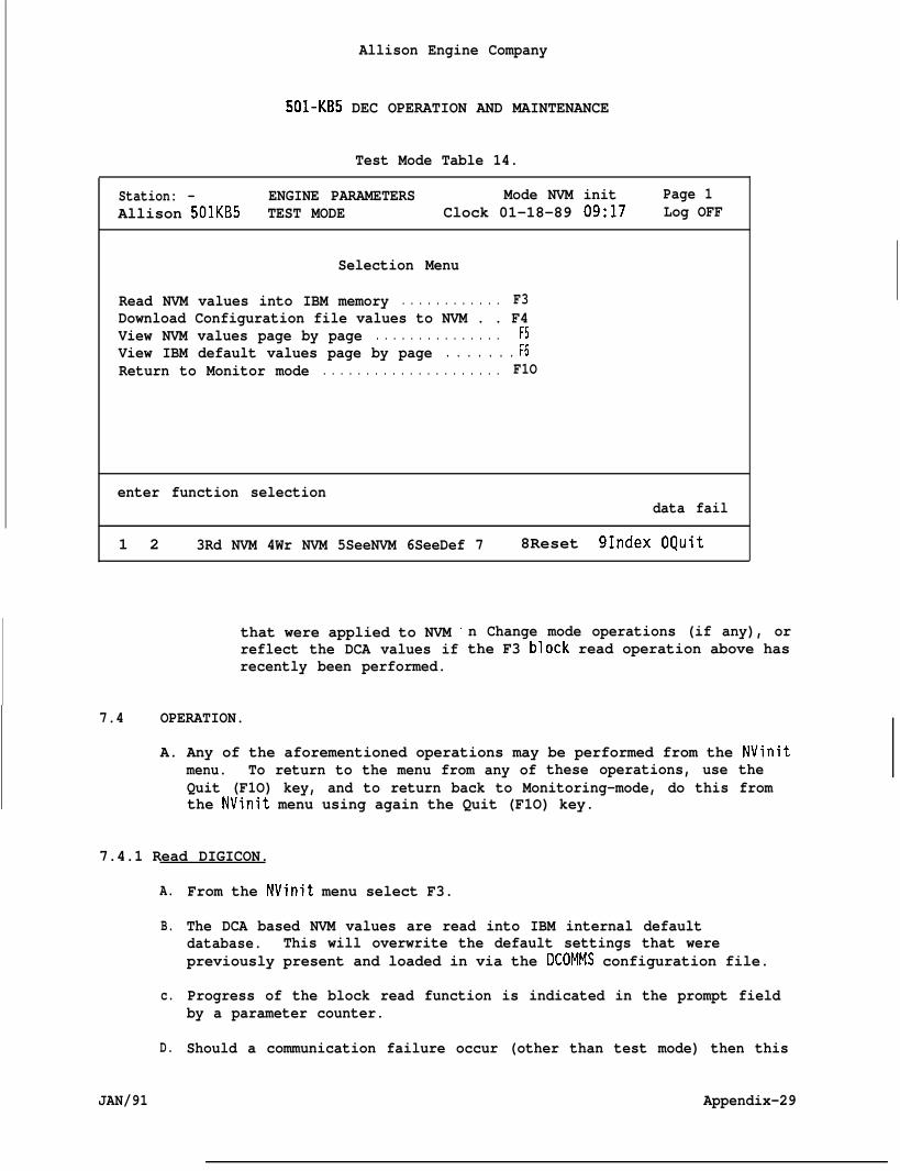
Allison Engine Company
501-KB5 DEC OPERATION AND MAINTENANCE
Test Mode Table 14.
Station: - ENGINE PARAMETERS Mode NVM init Page 1Allison 501KB5 TEST MODE Clock 01-18-89 09:17 Log OFF
Selection Menu
Read NVM values into IBM memory . . . . . . . . . . . . F3Download Configuration file values to NVM . . F4View NVM values page by page . . . . . . . . . . . . . . .View IBM default values page by page . . . . . . . ;:Return to Monitor mode . . . . . . . . . . . . . . . . . . . . . F1O
enter function selectiondata fail
1 2 3Rd NVM 4Wr NVM 5SeeNVM 6SeeDef 7 8Reset 91ndex OQuit
that were applied to NVM ~reflect the DCA values ifrecently been performed.
n Change mode operations (if any), orthe F3 b“ock read operation above has
7.4 OPERATION.
A. Any of the aforementioned operations may be performed from the NVinitthese operations, use themenu. To return to the menu from any of
Quit (F1O) key, and to return back to Monitoring-mode, do this fromthe NVinit menu using again the Quit (F1O) key.
7.4.1 Read DIGICON.
A.
B.
c.
D.
JAN/91
From the NVinit menu select F3.
The DCA based NVM values are read into IBM internal defaultdatabase. This will overwrite the default settings that werepreviously present and loaded in via the DCOMMS configuration file.
Progress of the block read function is indicated in the prompt fieldby a parameter counter.
Should a communication failure occur (other than test mode) then this
Appendix-29
Allison Engine Company
501 -KB5 DEC OPERATION AND MAINTENANCE
will be indicated, allowing the operator to retry the data transfer(and continue if successful), else ignore the communication failurefor this parameter (go on to next one, this is a bit dodgy - youshould either retry or abort and ascertain the cause of the problem)or else abort the block read function (return to NVinit menu).
7.4.2 Write DIGICON.
A.
B.
c.
D.
From the NVinit menu, select F4.
The DCA based NVM values are written to form IBM internal defaultdatabase. This will overwrite the default settings that werepreviously present in the DCA.
Progress of the block write function is indicated in the prompt fieldby a parameter counter.
Should a communication failure occur (other than test mode), thenthis will be indicated, allowing the operator to retry the datatransfer (and continue if successful), else ignore the communicationfailure for this parameter (go on to next one, this is a bit dodgy -you should either retry or abort and ascertain the cause of the prob-lem) or else abort the block read function (return to NVinit menu).
7.4.3 View DIGICON.
A.
B.
c.
D.
E.
F.
From the NVinit menu, select function F5.
The screen layout will follow that of the Monitor mode display, seeTable 1 (with mode set at NVMinit).
Parameters are read in from the DCA on a page by page basis asrequired (as each page is selected). The values displayed are theNVM values as opposed to the Monitor mode RAM based values.
The normal page selection facilities are available, as is the pageindex facility.
To return to the NVinit menu, use the Quit (F1O) key.
No modification to NVM values is permitted in this mode (this isperformed on a discrete basis using Change mode).
7.4.4 View IBM Default Settinas.
A.
B.
From the NVinit menu, select function F6.
The screen layout will follow. that of the Monitor mode display, seeTable 1 (with-mode set at NVinit).
Appendix-30 JAN/91
8.0
8.1
8.1.1
8.1.2
501 -KB5
Allison Engine Company
DEC OPERATION AND MAINTENANCE
C. Parameters displayed are the default settings as existing in the IBMinternal default database as opposed to the Monitor mode RAM basedvalues. These values will reflect the DCOMMS configuration filedefault settings plus any subsequent changes that were applied to NVMin Change mode operations (if any), or reflect the DCA values if theF3 block read operation (above) has recently been performed.
D. The normal page selection facilities are available, as is the pageindex facility.
E. To return to the NVinit menu, use the Quit (F1O) key.
F. No modification to default values is permitted in this mode (this isperformed on a discrete basis using Change mode, or off line using asuitable text editor).
USE OF DCOMMS.
BRIEF SYSTEM SUMMARY.
Monitoring Mode.
A.
B.
c.
D.
Monitoring mode is the primary operating mode, and it is from thismode that others (e.g. Historical data logging, Change) are entered.
DisDlay r)aqes may be selected either via the page selection keys(Horne,-End~ PgUp~ PgDn) or direct entry. -
I
An Index facility (F8) provides a list of display pages availablewithin the system.
A Save Paqe facility (F7) stores the currently selected Pa9e to aselected logical file:
Chanae Mode.
A.
B.
c.
D.
JAN/91
Change mode is entered via Monitoring mode, after entry of a validpassword. The password is ALLIGT (an acronym for Allison IndustrialGas Turbines).
Operator password access is to operator definable adjustableparameters, and subsequent parameter changes are limit protected.
The required parameter for adjustment is selected through use of pageselection and cursor movement keys.
Page Indexing (via F9) is available.
Appendix-31
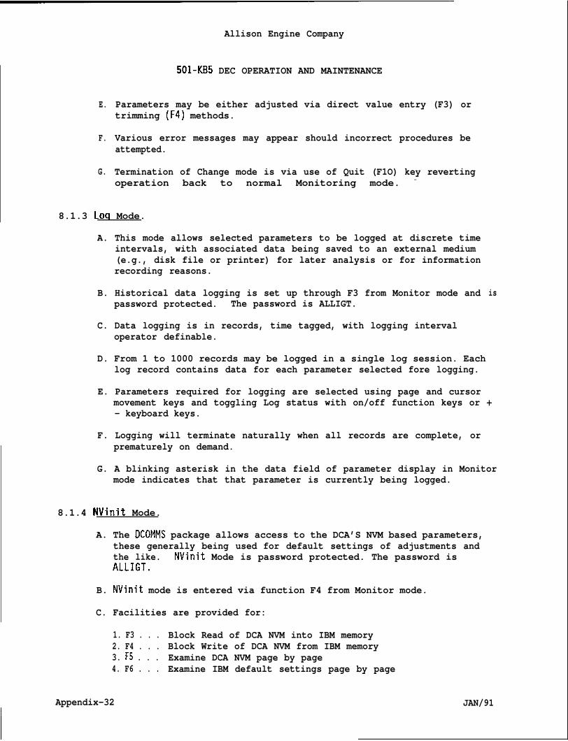
Allison Engine Company
501-KB5 DEC OPERATION AND MAINTENANCE
E.
F.
G.
Parameters may be either adjusted via direct value entry (F3) ortrimming (F4) methods.
Various error messages may appear should incorrect procedures beattempted.
Termination of Change mode is via use of Quit (F1O) key revertingoperation back to normal Monitoring mode. -
8.1.3 Loq Mode.
A. This mode allows selected parameters to be logged at discrete timeintervals, with associated data being saved to an external medium(e.g., disk file or printer) for later analysis or for informationrecording reasons.
B. Historical data logging is set up through F3 from Monitor mode andpassword protected. The password is ALLIGT.
C. Data logging is in records, time tagged, with logging intervaloperator definable.
is
D. From 1 to 1000 records may be logged in a single log session. Eachlog record contains data for each parameter selected fore logging.
E. Parameters required for logging are selected using page and cursormovement keys and toggling Log status with on/off function keys or +- keyboard keys.
F. Logging will terminate naturally when all records are complete, orprematurely on demand.
G. A blinking asterisk in the data field of parameter display in Monitormode indicates that that parameter is currently being logged.
8.1.4 NVinit Mode.
A. The DCOMMS package allows access to the DCA’S NVM based parameters,these generally being used for default settings of adjustments andthe like. NVinit Mode is password protected. The password isALLIGT.
B. NVinit mode is entered via function F4 from Monitor mode.
C. Facilities are provided for:
1. F3 . . . Block Read of DCA NVM into IBM memory2. F4 . . . Block Write of DCA NVM from IBM memory3. F5 . . . Examine DCA NVM page by page4. F6 . . . Examine IBM default settings page by page
Appendix-32 JAN/91
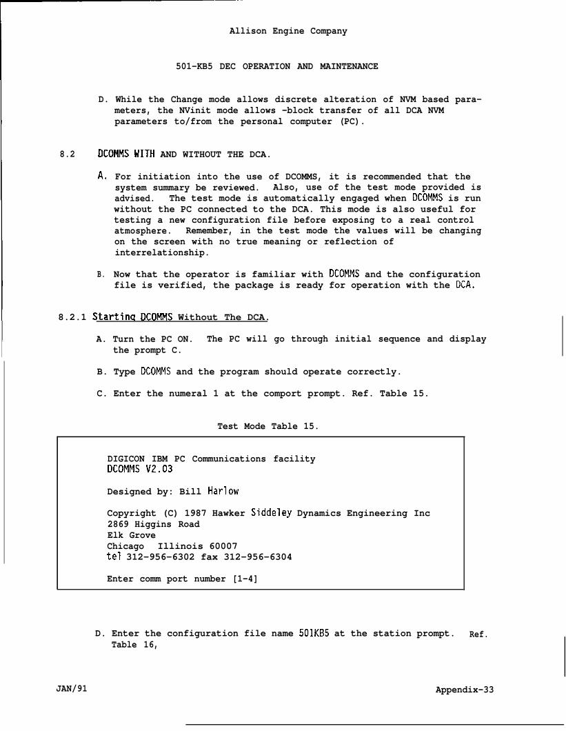
Allison Engine Company
501-KB5 DEC OPERATION AND MAINTENANCE
D. While the Change mode allows discrete alteration of NVM based para-meters, the NVinit mode allows -block transfer of all DCA NVMparameters to/from the personal computer (PC).
8.2 DCOMMS WITH AND WITHOUT THE DCA.
A,
B.
For initiation into the use of DCOMMS, it is recommended that thesystem summary be reviewed. Also, use of the test mode provided isadvised. The test mode is automatically engaged when DCOMMS is runwithout the PC connected to the DCA. This mode is also useful fortesting a new configuration file before exposing to a real controlatmosphere. Remember, in the test mode the values will be changingon the screen with no true meaning or reflection ofinterrelationship.
Now that the operator is familiar with DCOMMS and the configurationfile is verified, the package is ready for operation with the 13CA.
8.2.1 Startinq DCOMMS Without The DCA.
A. Turn the PC ON. The PC will go through initial sequence and displaythe prompt C.
B. Type DCOMMS and the program should operate correctly.
C. Enter the numeral 1 at the comport prompt. Ref. Table 15.
Test Mode Table 15.
DIGICON IBM PC Communications facilityDCOMMS V2.03
Designed by: Bill Harlow
Copyright (C) 1987 Hawker Siddeley Dynamics Engineering Inc2869 Higgins RoadElk GroveChicago Illinois 60007tel 312-956-6302 fax 312-956-6304
Enter comm port number [1-4]
D. Enter the configuration file name 501KB5 at the station prompt.Table 16,
Ref.
JAN/91 Appendix-33
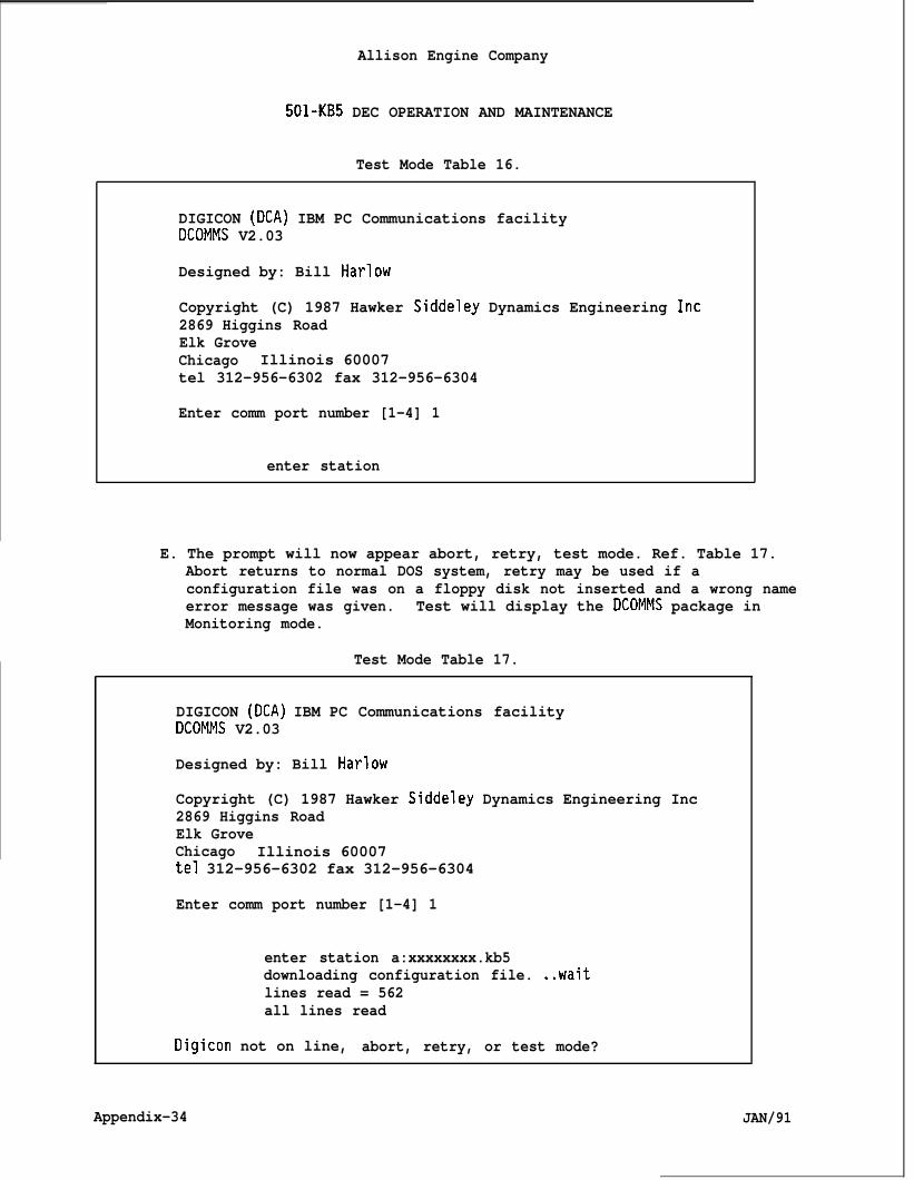
Allison Engine Company
501-KB5 DEC OPERATION AND MAINTENANCE
Test Mode Table 16.
DIGICON (DCA) IBM PC Communications facilityDCOMMS V2.03
Designed by: Bill Harlow
Copyright (C) 1987 Hawker Siddeley Dynamics Engineering Inc2869 Higgins RoadElk GroveChicago Illinois 60007tel 312-956-6302 fax 312-956-6304
Enter comm port number [1-4] 1
enter station
E. The prompt will now appear abort, retry, test mode. Ref. Table 17.Abort returns to normal DOS system, retry may be used if aconfiguration file was on a floppy disk not inserted and a wrong nameerror message was given. Test will display the DCOMMS package inMonitoring mode.
Test Mode Table 17.
DIGICON (DCA) IBM PC Communications facilityDCOMMS V2.03
Designed by: Bill Harlow
Copyright (C) 1987 Hawker Siddeley Dynamics Engineering Inc2869 Higgins RoadElk GroveChicago Illinois 60007tel 312-956-6302 fax 312-956-6304
Enter comm port number [1-4] 1
enter station a:xxxxxxxx.kb5downloading configuration file. ..waitlines read = 562all lines read
Digicon not on line, abort, retry, or test mode?
Appendix-34 JAN/91
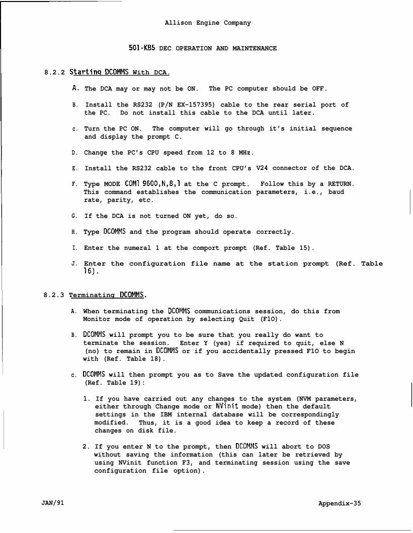
Allison Engine Company
501-KB5 DEC OPERATION AND MAINTENANCE
8.2.2 Startinq DCOMMS With DCA.
A.
B.
c.
D.
E.
F.
G.
H.
I.
J.
The DCA may or may not be ON. The PC computer should be OFF.
Install the RS232 (P/N EX-157395) cable to the rear serial port ofthe PC. Do not install this cable to the DCA until later.
Turn the PC ON. The computer will go through it’s initial sequenceand display the prompt C.
Change the PC’s CPU speed from 12 to 8 MHz.
Install the RS232 cable to the front CPU’s
Type MODE COM1 9600,N,8,1 at the C prompt.This command establishes the communicationrate, parity, etc.
If the DCA is not turned ON yet, do so.
Type DCOMMS and the program should operate
V24 connector of the DCA.
Follow this by a RETURN.parameters, i.e., baud
correctly.
Enter the numeral 1 at the comport prompt (Ref. Table 15).
Enter the configuration file name at the station prompt (Ref. Table.-.lb).
8.2.3 Terminating DCOMMS.
A.
B.
c.
JAN/91
When terminating the DCOMMS communications session, do this fromMonitor mode of operation by selecting Quit (F1O).
DCOMMS will prompt you to be sure that you really do want toterminate the session. Enter Y (yes) if required to quit, else N(no) to remain in DCOMMS or if you accidentally pressed F1O to beginwith (Ref. Table 18).
DCOMMS will then prompt you as to Save the updated configuration file(Ref. Table 19):
1. If you have carried out any changes to the system (NVM parameters,either through Change mode or NVinit mode) then the defaultsettings in the IBM internal database will be correspondinglymodified. Thus, it is a good idea to keep a record of thesechanges on disk file.
2. If you enter N to the prompt, then DCOMMS will abort to DOSwithout saving the information (this can later be retrieved byusing NVinit function F3, and terminating session using the saveconfiguration file option).
Appendix-35
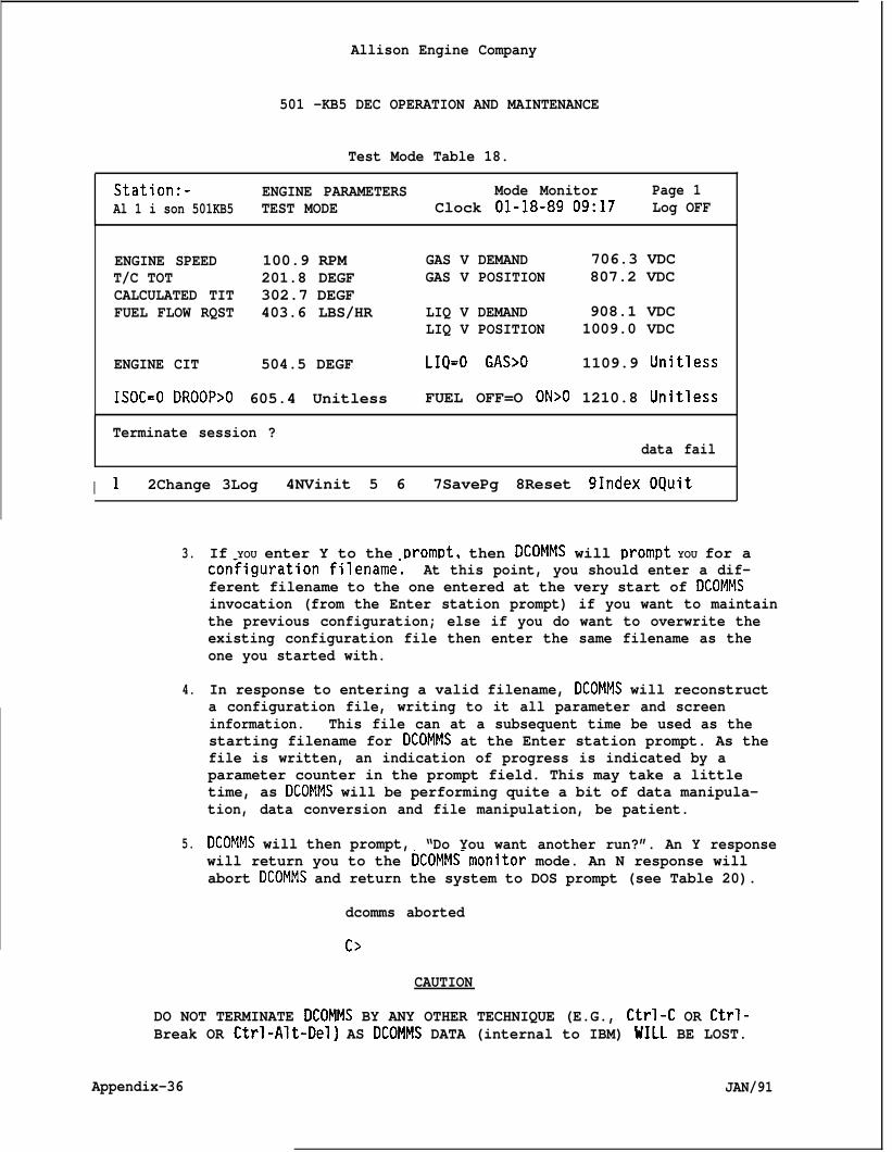
Allison Engine Company
501 -KB5 DEC OPERATION AND MAINTENANCE
Test Mode Table 18.
Station:- ENGINE PARAMETERS Mode Monitor Page 1Al 1 i son 501KB5 TEST MODE Clock O1-18-89 09:17 Log OFF
ENGINE SPEED 100.9 RPM GAS V DEMAND 706.3 VDCT/C TOT 201.8 DEGF GAS V POSITION 807.2 VDCCALCULATED TIT 302.7 DEGFFUEL FLOW RQST 403.6 LBS/HR LIQ V DEMAND 908.1 VDC
LIQ V POSITION 1009.0 VDC
ENGINE CIT 504.5 DEGF LIQ=O GAS>O 1109.9 Unitless
ISOC=O DROOP>O 605.4 Unitless FUEL OFF=O ON>O 1210.8 Unitless
Terminate session ?data fail
I 1 2Change 3Log 4NVinit 5 6 7SavePg 8Reset 91ndex OQuit
3.
4.
5.
If YOU enter Y to the ~rom~t, then DCOMMS will prompt YOU for acon~iguration filename; At this point, you should enter a dif-ferent filename to the one entered at the very start of DCOMMSinvocation (from the Enter station prompt) if you want to maintainthe previous configuration; else if you do want to overwrite theexisting configuration file then enter the same filename as theone you started with.
In response to entering a valid filename, DCOMMS will reconstructa configuration file, writing to it all parameter and screeninformation. This file can at a subsequent time be used as thestarting filename for DCOMMS at the Enter station prompt. As thefile is written, an indication of progress is indicated by aparameter counter in the prompt field. This may take a littletime, as DCOMMS will be performing quite a bit of data manipula-tion, data conversion and file manipulation, be patient.
DCOMMS will then prompt, “Do You want another run?”. An Y responsewill return you to the DCOMMS-monitor mode. An N response willabort DCOMMS and return the system to DOS prompt (see Table 20).
dcomms aborted
c>
CAUTION
DO NOT TERMINATE DCOMMS BY ANY OTHER TECHNIQUE (E.G., Ctrl-C OR Ctrl-Break OR Ctrl-Alt-Del) AS DCOMMS DATA (internal to IBM) WILL BE LOST.
Appendix-36 JAN/91
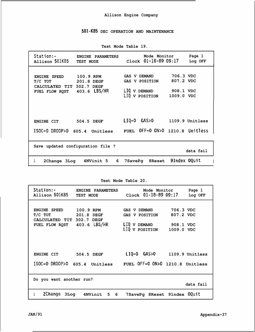
Allison Engine Company
501-KB5 DEC OPERATION AND MAINTENANCE
Test Mode Table 19.
Station:- ENGINE PARAMETERS Mode Monitor Page 1Allison 501KB5 TEST MODE Clock O1-18-89 09:17 Log OFF
ENGINE SPEED 100.9 RPMT/C TOT 201.8 DEGFCALCULATED TIT 302.7 DEGFFUEL FLOW RQST 403.6 LBS/HR
GAS V DEMAND 706.3 VDCGAS V POSITION 807.2 VDC
LIQ V DEMAND 908.1 VDCLIQ V POSITION 1009.0 VDC
ENGINE CIT 504.5 DEGF LIQ=O GAS>O 1109.9 Unitless
ISOC=O DROOP>O 605.4 Unitless FUEL OFF=O ON>O 1210.8 Unitless
Save updated configuration file ?data fail
1 2Change 3Log 4NVinit 5 6 7SavePg 8Reset 91ndex OQuit I
Test Mode Table 20.
Station:- ENGINE PARAMETERS Mode Monitor Page 1Allison 501KB5 TEST MODE Clock O1-18-89 09:17 Log OFF
ENGINE SPEED 100.9 RPM GAS V DEMAND 706.3 VDCT/C TOT 201.8 DEGF GAS V POSITION 807.2 VDCCALCULATED TIT 302.7 DEGFFUEL FLOW RQST 403.6 LBS/HR LIQ V DEMAND 908.1 VDC
LIQ V POSITION 1009.0 VDC
ENGINE CIT 504.5 DEGF LIQ=O GAS>O 1109.9 Unitless
ISOC=O DROOP>O 605.4 Unitless FUEL OFF=O ON>O 1210.8 Unitless
Do you want another run?data fail
1 2Change 3Log 4NVinit 5 6 7SavePg 8Reset 91ndex OQuit
JAN/91 Appendix-37
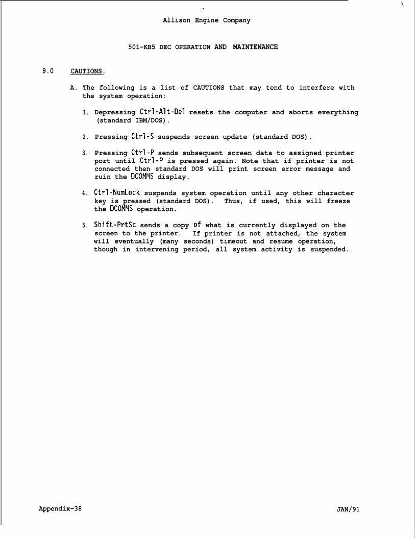
1,.-
Allison Engine Company
501-KB5 DEC OPERATION AND MAINTENANCE
9.0 CAUTIONS.
A. The following is a list of CAUTIONS that may tend to interfere withthe system operation:
1.
2.
3.
4.
5.
Depressing Ctrl-Alt-Del resets the computer and aborts everything(standard IBM/DOS).
Pressing Ctrl-S suspends screen update (standard DOS).
Pressing Ctrl-P sends subsequent screen data to assigned printerport until Ctrl-P is pressed again. Note that if printer is notconnected then standard DOS will print screen error message andruin the DCOMMS display.
Ctrl-NumLock suspends system operation until any other characterkey is pressed (standard DOS). Thus, if used, this will freezethe DCOMMS operation.
Shift-PrtSc sends a copy of what is currently displayed on thescreen to the printer. If printer is not attached, the systemwill eventually (many seconds) timeout and resume operation,though in intervening period, all system activity is suspended.
Appendix-38 JAN/91