Embed Size (px)
Citation preview


5 Step Commitment
1. Our Vision
(An aspiration to strive for) We are committed to being the most reliable and innovative supplier in the EMI/RFI shielding industry
and as our name implies,The Leader. In order to achieve this we will consistently strive to provide you with unparalleled service, innovation, and solutions.
2. Our Mission
(Our daily commitment to you) We are committed to consistently provide you with innovation and flexibility of design, engineering expertise,
and conscientious outstanding customer service that will provide you with the right product, delivered on time. We are dedicated to making you look good to your customers. We want your repeat business.
3. Our Products
(Precision engineered to work in your application) We are committed to product excellence, with our patented Circuit Board Shields (CBS), an extensive range
of copper beryllium (CuBe), a Conductive Elastomer product line, TechVENT Honeycomb Panels, TechMESH knitted mesh and microwave absorbers. Using this diverse product line Leader Tech is positioned to provide you with a ‘total shielding solution’ for all of your EMI/RFI shielding requirements.
4. Our Facilities
(Continually expanding to meet your needs) Leader Tech is committed to expansion wherever and whenever necessary. We are constantly expanding
our hardware and software capabilities while investing in new equipment to manufacture and deliver the most precise and cost efficient shielding in the industry. Through the continued support and backing of our parent company HEICO, the possibilities for new space and equipment are an ever present reality.
5. Our Services
(Consistent reliability each time you order) We are committed to excellent service. Our staff undergoes a rigorous daily product, sales, and service
education in order to serve you better. We want your calls answered by a person not a machine, someone trained to qualify your needs, and get answers to you when you need them. At Leader Tech we believe that the right people and the right equipment go hand in hand.
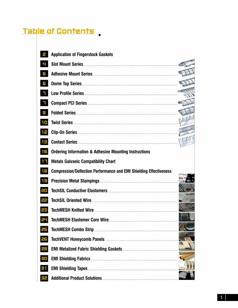
Table of Contents
Application of Fingerstock Gaskets
Slot Mount Series ...........................................................................................................................
Adhesive Mount Series ...............................................................................................................
Dome Top Series .............................................................................................................................
Low Profile Series ..........................................................................................................................
Compact PCI Series ......................................................................................................................
Folded Series .....................................................................................................................................
Twist Series ........................................................................................................................................
Clip-On Series ...................................................................................................................................
Contact Series ...................................................................................................................................
Ordering Information & Adhesive Mounting Instructions
Metals Galvanic Compatibility Chart
Compression/Deflection Performance and EMI Shielding Effectiveness
Precision Metal Stampings ......................................................................................................
TechSIL Conductive Elastomers ...........................................................................................
TechSIL Oriented Wire ................................................................................................................
TechMESH Knitted Wire .............................................................................................................
TechMESH Elastomer Core Wire ..........................................................................................
TechMESH Combo Strip .............................................................................................................
TechVENT Honeycomb Panels ...............................................................................................
EMI Metalized Fabric Shielding Gaskets ........................................................................
EMI Shielding Fabrics ..................................................................................................................
EMI Shielding Tapes .....................................................................................................................
Additional Product Solutions ...................................................................................................
1
2
4
6
6
7
7
8
10
12
13
16
17
18
19
20
22
23
24
25
26
28
30
31
32
C o p p e r B e r y l l i u m F i n g e r s t o c k
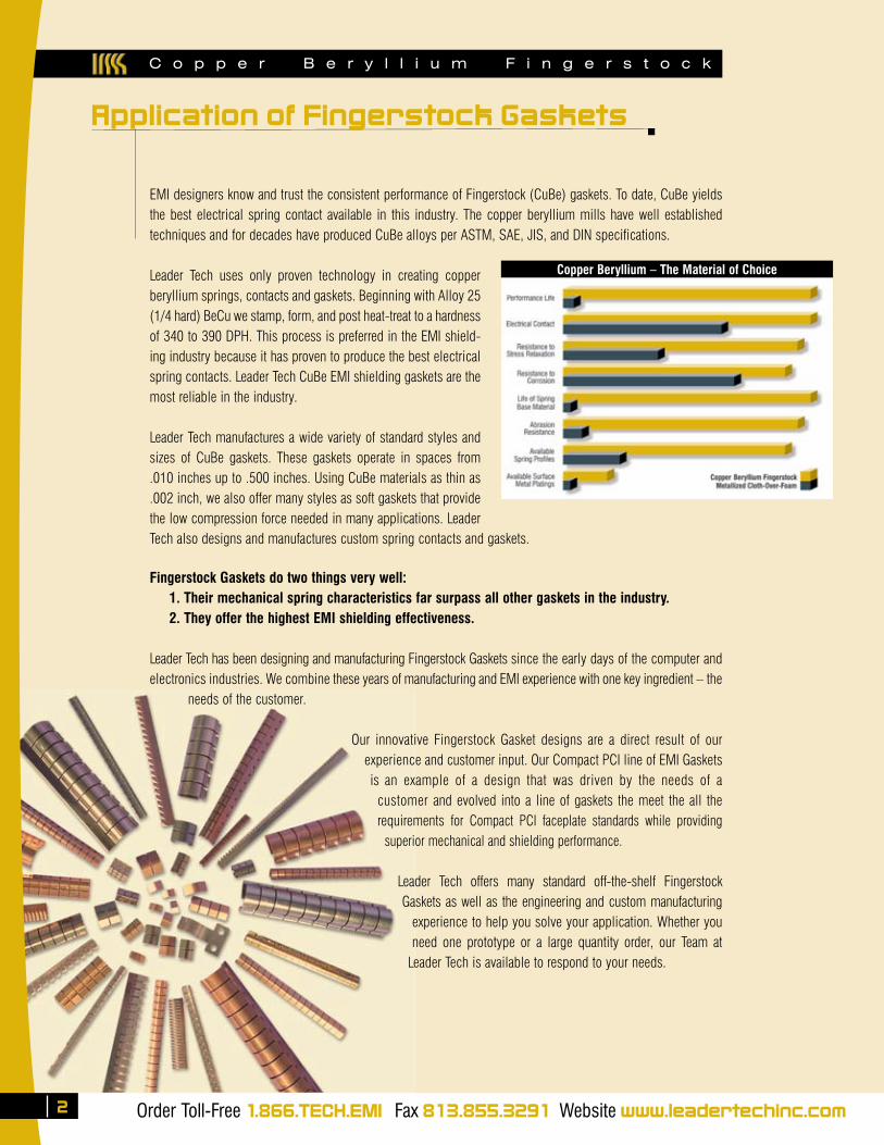
EMI designers know and trust the consistent performance of Fingerstock (CuBe) gaskets. To date, CuBe yields the best electrical spring contact available in this industry. The copper beryllium mills have well established techniques and for decades have produced CuBe alloys per ASTM, SAE, JIS, and DIN specifications.
Leader Tech uses only proven technology in creating copper beryllium springs, contacts and gaskets. Beginning with Alloy 25 (1/4 hard) BeCu we stamp, form, and post heat-treat to a hardness of 340 to 390 DPH. This process is preferred in the EMI shield-ing industry because it has proven to produce the best electrical spring contacts. Leader Tech CuBe EMI shielding gaskets are the most reliable in the industry.
Leader Tech manufactures a wide variety of standard styles and sizes of CuBe gaskets. These gaskets operate in spaces from .010 inches up to .500 inches. Using CuBe materials as thin as .002 inch, we also offer many styles as soft gaskets that provide the low compression force needed in many applications. Leader Tech also designs and manufactures custom spring contacts and gaskets.
Fingerstock Gaskets do two things very well: 1. Their mechanical spring characteristics far surpass all other gaskets in the industry. 2. They offer the highest EMI shielding effectiveness.
Leader Tech has been designing and manufacturing Fingerstock Gaskets since the early days of the computer and electronics industries. We combine these years of manufacturing and EMI experience with one key ingredient – the
needs of the customer.
Our innovative Fingerstock Gasket designs are a direct result of our experience and customer input. Our Compact PCI line of EMI Gaskets is an example of a design that was driven by the needs of a
customer and evolved into a line of gaskets the meet the all the requirements for Compact PCI faceplate standards while providing
superior mechanical and shielding performance.
Leader Tech offers many standard off-the-shelf Fingerstock Gaskets as well as the engineering and custom manufacturing
experience to help you solve your application. Whether you need one prototype or a large quantity order, our Team at
Leader Tech is available to respond to your needs.
Copper Beryllium – The Material of Choice
Order Toll-Free 1.866.TECH.EMI Fax 813.855.3291 Website www.leadertechinc.com
Application of Fingerstock Gaskets
2
The Leading Edge in EMI Shielding Technology ✔RoHSCOMPLIANT
3
Slot Mount Series see page 4 Folded Series see page 8
Twist Series see page 10 Compact PCI Series see page 7
Detail ADual Slot Installation
A
B
Detail BSingle Slot Installation
Detail A Detail B
A
B
Mounting Concepts
C o p p e r B e r y l l i u m F i n g e r s t o c k

C o p p e r B e r y l l i u m F i n g e r s t o c k
Order Toll-Free 1.866.TECH.EMI Fax 813.855.3291 Website www.leadertechinc.com
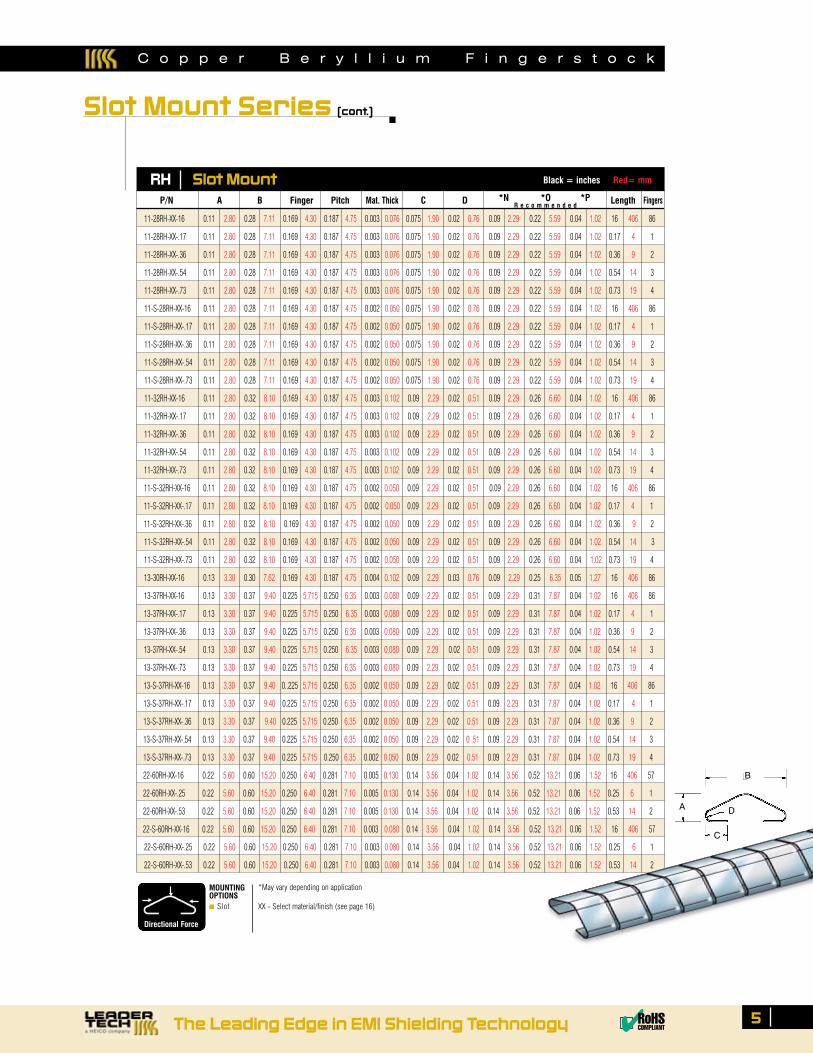
11-32AF-XX-16 0.11 2.80 0.32 8.10 0.169 4.30 0.187 4.75 0.004 0.102 0.085 2.159 0.020 0.508 0.09 2.286 0.26 6.604 0.04 1.016 16 406 85
11-S-32AF-XX-16 0.11 2.80 0.32 8.10 0.169 4.30 0.187 4.75 0.002 0.050 0.085 2.159 0.020 0.508 0.09 2.286 0.26 6.604 0.04 1.016 16 406 85
22-60AF-XX-16 0.22 5.59 0.60 15.24 0.250 6.35 0.282 7.16 0.005 0.127 0.140 3.556 0.035 0.889 0.14 3.556 0.52 13.208 0.07 1.778 16 406 57
22-S-60AF-XX-16 0.22 5.59 0.60 15.24 0.250 6.35 0.282 7.16 0.003 0.080 0.140 3.556 0.035 0.889 0.14 3.556 0.52 13.208 0.07 1.778 16 406 57
4
AF Alternate Finger Slot Mount Black = inches Red= mm
P/N A B Finger Pitch Mat. Thick C D *E *F *G Length Fingers
Slot Mount Series
Slot mount gaskets are a standard in the electronic enclosure industry. These gaskets are used in shorter lengths as ESD contacts and longer lengths as EMI gaskets, which clip into slots or slide onto mounted tracks.
MaterialThickness
Length of slot and distance between slotsis dependent on hole mounting pattern
E
F
G
Alternate Finger Mounting Hole Recommendations
Compression/Deflection
(Alternate Finger Slot Mount Series)
50
45
40
35
30
25
20
15
10
5
0
70
60
50
40
30
20
10
0 20 40 60 80
Load
(po
unds
per
line
ar f
oot)
Load (kilograms-force per linear m
eter)
Deflection (%)
11-32AF
R e c o m m e n d e d
Length of slot is dependenton the number of fingrs used
N
O
Material Thickness
RH Mounting Hole Pattern
P
MOUNTINGOPTIONS■ Slot
B
A
C
*May vary depending on application
XX - Select material/finish (see page 16)
Directional Force
D
The Leading Edge in EMI Shielding Technology ✔RoHSCOMPLIANT
5
DA
B
C
Directional Force
MOUNTINGOPTIONS■ Slot
P/N A B Finger Pitch Mat. Thick C D *N *O *P Length Fingers
11-28RH-XX-16 0.11 2.80 0.28 7.11 0.169 4.30 0.187 4.75 0.003 0.076 0.075 1.90 0.02 0.76 0.09 2.29 0.22 5.59 0.04 1.02 16 406 86
11-28RH-XX-.17 0.11 2.80 0.28 7.11 0.169 4.30 0.187 4.75 0.003 0.076 0.075 1.90 0.02 0.76 0.09 2.29 0.22 5.59 0.04 1.02 0.17 4 1
11-28RH-XX-.36 0.11 2.80 0.28 7.11 0.169 4.30 0.187 4.75 0.003 0.076 0.075 1.90 0.02 0.76 0.09 2.29 0.22 5.59 0.04 1.02 0.36 9 2
11-28RH-XX-.54 0.11 2.80 0.28 7.11 0.169 4.30 0.187 4.75 0.003 0.076 0.075 1.90 0.02 0.76 0.09 2.29 0.22 5.59 0.04 1.02 0.54 14 3
11-28RH-XX-.73 0.11 2.80 0.28 7.11 0.169 4.30 0.187 4.75 0.003 0.076 0.075 1.90 0.02 0.76 0.09 2.29 0.22 5.59 0.04 1.02 0.73 19 4
11-S-28RH-XX-16 0.11 2.80 0.28 7.11 0.169 4.30 0.187 4.75 0.002 0.050 0.075 1.90 0.02 0.76 0.09 2.29 0.22 5.59 0.04 1.02 16 406 86
11-S-28RH-XX-.17 0.11 2.80 0.28 7.11 0.169 4.30 0.187 4.75 0.002 0.050 0.075 1.90 0.02 0.76 0.09 2.29 0.22 5.59 0.04 1.02 0.17 4 1
11-S-28RH-XX-.36 0.11 2.80 0.28 7.11 0.169 4.30 0.187 4.75 0.002 0.050 0.075 1.90 0.02 0.76 0.09 2.29 0.22 5.59 0.04 1.02 0.36 9 2
11-S-28RH-XX-.54 0.11 2.80 0.28 7.11 0.169 4.30 0.187 4.75 0.002 0.050 0.075 1.90 0.02 0.76 0.09 2.29 0.22 5.59 0.04 1.02 0.54 14 3
11-S-28RH-XX-.73 0.11 2.80 0.28 7.11 0.169 4.30 0.187 4.75 0.002 0.050 0.075 1.90 0.02 0.76 0.09 2.29 0.22 5.59 0.04 1.02 0.73 19 4
11-32RH-XX-16 0.11 2.80 0.32 8.10 0.169 4.30 0.187 4.75 0.003 0.102 0.09 2.29 0.02 0.51 0.09 2.29 0.26 6.60 0.04 1.02 16 406 86
11-32RH-XX-.17 0.11 2.80 0.32 8.10 0.169 4.30 0.187 4.75 0.003 0.102 0.09 2.29 0.02 0.51 0.09 2.29 0.26 6.60 0.04 1.02 0.17 4 1
11-32RH-XX-.36 0.11 2.80 0.32 8.10 0.169 4.30 0.187 4.75 0.003 0.102 0.09 2.29 0.02 0.51 0.09 2.29 0.26 6.60 0.04 1.02 0.36 9 2
11-32RH-XX-.54 0.11 2.80 0.32 8.10 0.169 4.30 0.187 4.75 0.003 0.102 0.09 2.29 0.02 0.51 0.09 2.29 0.26 6.60 0.04 1.02 0.54 14 3
11-32RH-XX-.73 0.11 2.80 0.32 8.10 0.169 4.30 0.187 4.75 0.003 0.102 0.09 2.29 0.02 0.51 0.09 2.29 0.26 6.60 0.04 1.02 0.73 19 4
11-S-32RH-XX-16 0.11 2.80 0.32 8.10 0.169 4.30 0.187 4.75 0.002 0.050 0.09 2.29 0.02 0.51 0.09 2.29 0.26 6.60 0.04 1.02 16 406 86
11-S-32RH-XX-.17 0.11 2.80 0.32 8.10 0.169 4.30 0.187 4.75 0.002 0.050 0.09 2.29 0.02 0.51 0.09 2.29 0.26 6.60 0.04 1.02 0.17 4 1
11-S-32RH-XX-.36 0.11 2.80 0.32 8.10 0.169 4.30 0.187 4.75 0.002 0.050 0.09 2.29 0.02 0.51 0.09 2.29 0.26 6.60 0.04 1.02 0.36 9 2
11-S-32RH-XX-.54 0.11 2.80 0.32 8.10 0.169 4.30 0.187 4.75 0.002 0.050 0.09 2.29 0.02 0.51 0.09 2.29 0.26 6.60 0.04 1.02 0.54 14 3
11-S-32RH-XX-.73 0.11 2.80 0.32 8.10 0.169 4.30 0.187 4.75 0.002 0.050 0.09 2.29 0.02 0.51 0.09 2.29 0.26 6.60 0.04 1.02 0.73 19 4
13-30RH-XX-16 0.13 3.30 0.30 7.62 0.169 4.30 0.187 4.75 0.004 0.102 0.09 2.29 0.03 0.76 0.09 2.29 0.25 6.35 0.05 1.27 16 406 86
13-37RH-XX-16 0.13 3.30 0.37 9.40 0.225 5.715 0.250 6.35 0.003 0.080 0.09 2.29 0.02 0.51 0.09 2.29 0.31 7.87 0.04 1.02 16 406 86
13-37RH-XX-.17 0.13 3.30 0.37 9.40 0.225 5.715 0.250 6.35 0.003 0.080 0.09 2.29 0.02 0.51 0.09 2.29 0.31 7.87 0.04 1.02 0.17 4 1
13-37RH-XX-.36 0.13 3.30 0.37 9.40 0.225 5.715 0.250 6.35 0.003 0.080 0.09 2.29 0.02 0.51 0.09 2.29 0.31 7.87 0.04 1.02 0.36 9 2
13-37RH-XX-.54 0.13 3.30 0.37 9.40 0.225 5.715 0.250 6.35 0.003 0.080 0.09 2.29 0.02 0.51 0.09 2.29 0.31 7.87 0.04 1.02 0.54 14 3
13-37RH-XX-.73 0.13 3.30 0.37 9.40 0.225 5.715 0.250 6.35 0.003 0.080 0.09 2.29 0.02 0.51 0.09 2.29 0.31 7.87 0.04 1.02 0.73 19 4
13-S-37RH-XX-16 0.13 3.30 0.37 9.40 0..225 5.715 0.250 6.35 0.002 0.050 0.09 2.29 0.02 0.51 0.09 2.29 0.31 7.87 0.04 1.02 16 406 86
13-S-37RH-XX-.17 0.13 3.30 0.37 9.40 0.225 5.715 0.250 6.35 0.002 0.050 0.09 2.29 0.02 0.51 0.09 2.29 0.31 7.87 0.04 1.02 0.17 4 1
13-S-37RH-XX-.36 0.13 3.30 0.37 9.40 0.225 5.715 0.250 6.35 0.002 0.050 0.09 2.29 0.02 0.51 0.09 2.29 0.31 7.87 0.04 1.02 0.36 9 2
13-S-37RH-XX-.54 0.13 3.30 0.37 9.40 0.225 5.715 0.250 6.35 0.002 0.050 0.09 2.29 0.02 0 .51 0.09 2.29 0.31 7.87 0.04 1.02 0.54 14 3
13-S-37RH-XX-.73 0.13 3.30 0.37 9.40 0.225 5.715 0.250 6.35 0.002 0.050 0.09 2.29 0.02 0.51 0.09 2.29 0.31 7.87 0.04 1.02 0.73 19 4
22-60RH-XX-16 0.22 5.60 0.60 15.20 0.250 6.40 0.281 7.10 0.005 0.130 0.14 3.56 0.04 1.02 0.14 3.56 0.52 13.21 0.06 1.52 16 406 57
22-60RH-XX-.25 0.22 5.60 0.60 15.20 0.250 6.40 0.281 7.10 0.005 0.130 0.14 3.56 0.04 1.02 0.14 3.56 0.52 13.21 0.06 1.52 0.25 6 1
22-60RH-XX-.53 0.22 5.60 0.60 15.20 0.250 6.40 0.281 7.10 0.005 0.130 0.14 3.56 0.04 1.02 0.14 3.56 0.52 13.21 0.06 1.52 0.53 14 2
22-S-60RH-XX-16 0.22 5.60 0.60 15.20 0.250 6.40 0.281 7.10 0.003 0.080 0.14 3.56 0.04 1.02 0.14 3.56 0.52 13.21 0.06 1.52 16 406 57
22-S-60RH-XX-.25 0.22 5.60 0.60 15.20 0.250 6.40 0.281 7.10 0.003 0.080 0.14 3.56 0.04 1.02 0.14 3.56 0.52 13.21 0.06 1.52 0.25 6 1
22-S-60RH-XX-.53 0.22 5.60 0.60 15.20 0.250 6.40 0.281 7.10 0.003 0.080 0.14 3.56 0.04 1.02 0.14 3.56 0.52 13.21 0.06 1.52 0.53 14 2
RH Slot Mount Black = inches Red= mm
Slot Mount Series (cont.)
R e c o m m e n d e d
*May vary depending on application
XX - Select material/finish (see page 16)
C o p p e r B e r y l l i u m F i n g e r s t o c k

C o p p e r B e r y l l i u m F i n g e r s t o c k
Adhesive Mount Series
The Dome Top Gaskets are known for their large surface area for electrical contact and smooth wiping action. Also available in a solid top profile allowing for omni-directional wiping. Together with the Slot Mount Series, the Dome Top Gaskets are a mainstay in the enclosure/chassis industries. Commonly mounted with adhesive tape.
AH Adhesive Mount Black = inches Red= mm Comp = Compressed
DT Dome Top Black = inches Red= mm Comp = Compressed
A
B
C
The AH series gaskets are adhesive mounted general-purpose gaskets used in both compression and wiping applications. Sizes range from .11” (2.8mm) to .32” (8.1 mm) in height. Applications include electronic enclosures, shielded cabinets, and MRI chamber doors.
XX - Select material/finish (see page 16)Directional Force
MOUNTINGOPTIONS■ Tape
A
B
Directional Force
MOUNTINGOPTIONS■ Tape
The Dome Top gaskets have fully independent fingers that are adhesive mounted. Their smooth curve provides a large area for electrical contact and smooth wiping action.
XX - Select material/finish (see page 16)
11-32AH-XX-16 0.11 2.80 0.32 8.10 0.170 4.30 0.188 4.80 0.003 0.080 0.200 5 .100 0.390 9.910 0.04 1.016 16 406 86 0.145
11-S-32AH-XX-16 0.11 2.80 0.32 8.10 0.170 4.30 0.188 4.80 0.002 0.050 0.200 5.100 0.390 9.910 0.04 1.016 16 406 86 0.145
13-37AH-XX-16 0.13 3.30 0.37 9.40 0.225 5.70 0.250 6.40 0.003 0.080 0.210 5.300 0.510 12.950 0.05 1.143 16 406 64 0.145
13-S-37AH-XX-16 0.13 3.30 0.37 9.40 0.225 5.70 0.250 6.40 0.002 0.050 0.210 5.300 0.510 12.950 0.05 1.143 16 406 64 0.145
14-38AH-XX-16 0.14 3.56 0.38 9.65 0.343 8.71 0.375 9.53 0.004 0.102 0.200 5.080 0.525 13.34 0.05 1.270 16 406 43 0.145
22-60AH-XX-16 0.22 5.60 0.60 15.24 0.344 8.74 0.375 9.50 0.005 0.130 0.280 7.100 0.730 18.540 0.06 1.397 16 406 43 0.200
22-S-60AH-XX-16 0.22 5.60 0.60 15.24 0.344 8.74 0.375 9.50 0.003 0.080 0.280 7.100 0.730 18.540 0.06 1.397 16 406 43 0.200
32-78AH-XX-16 0.32 8.10 0.78 19.80 0.344 8.74 0.375 9.50 0.004 0.102 0.450 11.400 0.980 24.890 0.12 3.048 16 406 43 0.375
32-S-78AH-XX-16 0.32 8.10 0.78 19.80 0.344 8.74 0.375 9.50 0.003 0.080 0.450 11.400 0.980 24.890 0.12 3.048 16 406 43 0.375
P/N A B Finger Pitch Mat. Thick C Comp Width Comp Height Length Fingers Tape
8-45DT-XX-15 0.08 2.03 0.45 11.4 0.100 2.54 0.125 3.18 0.003 0.076 0.51 13.0 0.040 1.02 15 381 150 0.145
8-S-45DT-XX-15 0.08 2.03 0.45 11.4 0.100 2.54 0.125 3.18 0.002 0.050 0.51 13.0 0.040 1.02 15 381 150 0.145
11-35DT-XX-15 0.11 2.79 0.35 8.89 0.170 4.32 0.188 4.78 0.003 0.076 0.38 9.65 0.055 1.40 15 381 80 0.100
11-S-35DT-XX-15 0.11 2.79 0.35 8.89 0.170 4.32 0.188 4.78 0.002 0.050 0.38 9.65 0.055 1.40 15 381 80 0.100
14-45DT-XX-15 0.14 3.56 0.45 11.4 0.228 5.79 0.250 6.35 0.003 0.076 0.51 13.0 0.070 1.78 15 381 60 0.100
14-S-45DT-XX-15 0.14 3.56 0.45 11.4 0.228 5.79 0.250 6.35 0.002 0.050 0.51 13.0 0.070 1.78 15 381 60 0.100
22-62DT-XX-15 0.22 5.59 0.62 15.7 0.345 8.76 0.375 9.53 0.004 0.102 0.76 19.3 0.100 2.54 15 381 40 0.100
22-S-62DT-XX-15 0.22 5.59 0.62 15.7 0.345 8.76 0.375 9.53 0.003 0.076 0.76 19.3 0.100 2.54 15 381 40 0.100
P/N A B Finger Pitch Mat. Thick Comp Width Comp Height Length Fingers Tape
DTS Dome Top Solid Black = inches Red= mm Comp = Compressed
A
B
MOUNTINGOPTIONS■ Tape
The Dome Top “Solid” Series gaskets have a strip that connects each finger along the top. This allows for unique angular wiping action without snagging. Other features are the same as the Dome Top Series.
XX - Select material/finish (see page 16)Directional Force
11-35DTS-XX-15 0.11 2.79 0.35 8.89 0.170 4.32 0.188 4.78 0.003 0.076 0.38 9.65 0.055 1.40 15 381 80 0.100
11-S-35DTS-XX-15 0.11 2.79 0.35 8.89 0.170 4.32 0.188 4.78 0.002 0.050 0.38 9.65 0.055 1.40 15 381 80 0.100
14-45DTS-XX-15 0.14 3.56 0.45 11.4 0.250 6.35 0.250 6.35 0.003 0.076 0.51 13.0 0.070 1.78 15 381 60 0.100
14-S-45DTS-XX-15 0.14 3.56 0.45 11.4 0.250 6.35 0.250 6.35 0.002 0.050 0.51 13.0 0.070 1.78 15 381 60 0.100
22-62DTS-XX-15 0.22 5.59 0.62 15.7 0.375 9.53 0.375 9.53 0.004 0.102 0.76 19.3 0.100 2.54 15 381 40 0.100
22-S-62DTS-XX-15 0.22 5.59 0.62 15.7 0.375 9.53 0.375 9.53 0.003 0.076 0.76 19.3 0.100 2.54 15 381 40 0.100
P/N A B Finger Pitch Mat. Thick Comp Width Comp Height Length Fingers Tape
Dome Top Series
6 Order Toll-Free 1.866.TECH.EMI Fax 813.855.3291 Website www.leadertechinc.com
D A
B
C
Low Profile Series
LPAH Low Profile Adhesive Mount Black = inches Red= mm
LPC Low Profile Clip Black = inches Red= mm
PCI Contact Black = inches Red= mm
PCI SeriesHigh performance Compact PCI Gaskets designed for easy card insertion in rack mount applications. This gasket is available in two different sizes to accommodate different customer extrusions. They are available in both Copper Beryllium and Stainless Steel.
A
B
MOUNTINGOPTIONS■ Tape
The low profile series gaskets incorporate design features that allow for some of the lowest compression forces in the industry, while achieving high performance shielding effective-ness. These gaskets are ideally suited for small aperture applications.
XX - Select material/finish (see page 16)
A
B
Directional Force
MOUNTINGOPTIONS■ Clip■ Tape
Directional Force
MOUNTINGOPTIONS■ Extrusion
Directional Force
8-45LPAH-XX-16 0.08 2.0 0.45 11.4 0.10 2.5 0.125 3.18 0.004 .100 16 406 128 .200
8-S-45LPAH-XX-16 0.08 2.0 0.45 11.4 0.10 2.5 0.125 3.18 0.003 0.08 16 406 128 .200
12-60LPAH-XX-16 0.12 3.0 0.60 15.2 0.10 2.5 0.125 3.18 0.004 .100 16 406 128 .200
12-S-60LPAH-XX-16 0.12 3.0 0.60 15.2 0.10 2.5 0.125 3.18 0.003 0.08 16 406 128 .200
P/N A B Finger Pitch Mat. Thick Length Fingers Tape
8-45LPC-060-XX-16 0.06 1.52 0.45 11.4 0.10 2.5 0.125 3.18 .100 2.54 0.004 .100 16 406 128 0.060 .200
8-S-45LPC-060-XX-16 0.06 1.52 0.45 11.4 0.10 2.5 0.125 3.18 .100 2.54 0.003 0.08 16 406 128 0.060 .200
12-60LPC-060-XX-16 0.09 2.29 0.60 15.2 0.10 2.5 0.125 3.18 .140 3.56 0.004 .100 16 406 128 0.060 .200
12-S-60LPC-060-XX-16 0.09 2.29 0.60 15.2 0.10 2.5 0.125 3.18 .140 3.56 0.003 0.08 16 406 128 0.060 .200
P/N A B Finger Pitch C Mat. Thick Length Fingers Clip ID Tape
7-19PCI-XX-4.6 0.067 1.7 0.177 4.5 0.18 4.6 0.2 5.1 0.002 0.050 0.050 1.270 0.011 0.279 4.60 117 23
7-19PCI-XX-9.0 0.067 1.7 0.177 4.5 0.18 4.6 0.2 5.1 0.002 0.050 0.050 1.270 0.011 0.279 9.00 229 45
7-19PCI-XX-14.40 0.067 1.7 0.177 4.5 0.18 4.6 0.2 5.1 0.002 0.050 0.050 1.270 0.011 0.279 14.40 366 72
7-19PCI-SS-4.6 0.067 1.7 0.177 4.5 0.18 4.6 0.2 5.1 0.002 0.050 0.050 1.270 0.011 0.279 4.60 117 23
7-19PCI-SS-9.0 0.067 1.7 0.177 4.5 0.18 4.6 0.2 5.1 0.002 0.050 0.050 1.270 0.011 0.279 9.00 229 45
7-19PCI-SS-14.40 0.067 1.7 0.177 4.5 0.18 4.6 0.2 5.1 0.002 0.050 0.050 1.270 0.011 0.279 14.40 366 72
8-19PCI-XX-4.6 0.067 1.7 0.190 4.8 0.18 4.6 0.2 5.1 0.002 0.050 0.045 1.143 0.015 0.381 4.60 117 23
8-19PCI-XX-9.0 0.067 1.7 0.190 4.8 0.18 4.6 0.2 5.1 0.002 0.050 0.045 1.143 0.015 0.381 9.00 229 45
8-19PCI-XX-14.40 0.067 1.7 0.190 4.8 0.18 4.6 0.2 5.1 0.002 0.050 0.045 1.143 0.015 0.381 14.40 366 72
8-19PCI-SS-4.6 0.067 1.7 0.190 4.8 0.18 4.6 0.2 5.1 0.002 0.050 0.045 1.143 0.015 0.381 4.60 117 23
8-19PCI-SS-9.0 0.067 1.7 0.190 4.8 0.18 4.6 0.2 5.1 0.002 0.050 0.045 1.143 0.015 0.381 9.00 229 45
8-19PCI-SS-14.40 0.067 1.7 0.190 4.8 0.18 4.6 0.2 5.1 0.002 0.050 0.045 1.143 0.015 0.381 14.40 366 72
P/N A B Finger Pitch Mat. Thick C D Length Fingers
XX - Select material/finish (see page 16)
XX - Select material/finish (see page 16)
C o p p e r B e r y l l i u m F i n g e r s t o c k
The Leading Edge in EMI Shielding Technology ✔RoHSCOMPLIANT
C
5

C o p p e r B e r y l l i u m F i n g e r s t o c k
Folded Series
8
Leader Tech's Folded Gasket series are industry standard general-purpose gaskets that allow a large range of deflection and compression forces. These gaskets are available with or without tape for alternate attachment methods. Also available in a snag-free version where, under compression, the leading edge of the gasket slides into an extended and folded base which prevents possible damage to the gasket.
FS Folded Black = inches Red= mm
Order Toll-Free 1.866.TECH.EMI Fax 813.855.3291 Website www.leadertechinc.com
A
B
C
MOUNTINGOPTIONS■ Tape■ Solder■ Rivet
The Leader Tech FS gaskets are industry standard general-purpose gaskets that allow a large range of deflection and compression forces. These gaskets are available without tape for alternate attachment methods. Consult factory for information.
XX - Select material/finish (see page 16)Directional Force
11-28-FS-XX-16 0.11 2.79 0.28 7.11 0.170 4.32 0.188 4.78 0.003 0.076 0.24 5.842 0.37 9.4 0.065 1.65 16 406 85 0.145
11-S-28-FS-XX-16 0.11 2.79 0.28 7.11 0.170 4.32 0.188 4.78 0.002 0.050 0.24 5.842 0.37 9.4 0.065 1.65 16 406 85 0.145
14-37FS-XX-16 0.14 3.56 0.36 9.14 0.228 5.79 0.250 6.35 0.003 0.076 0.32 7.874 0.50 12.7 0.070 1.78 16 406 64 0.200
14-37FS-XX-300 0.14 3.56 0.36 9.14 0.230 5.84 0.250 6.35 0.003 0.076 0.32 7.874 0.50 12.7 0.070 1.78 300 7620 1200 0.200
14-S-37FS-XX-16 0.14 3.56 0.36 9.14 0.228 5.79 0.250 6.35 0.002 0.050 0.31 7.874 0.50 12.7 0.070 1.78 16 406 64 0.200
23-60FS-XX-24 0.23 5.84 0.60 15.24 0.343 8.71 0.375 9.53 0.004 0.102 0.50 12.700 0.77 19.6 0.040 1.02 24 610 64 0.250
23-S-60FS-XX-24 0.23 5.84 0.60 15.24 0.343 8.71 0.375 9.53 0.003 0.076 0.50 12.700 0.77 19.6 0.040 1.02 24 610 64 0.250
25-78FS-XX-24 0.25 6.35 0.78 19.81 0.335 8.51 0.375 9.53 0.005 0.127 0.53 13.462 0.94 23.9 0.080 2.03 24 610 64 0.375
25-78FS-XX-300 0.25 6.35 0.78 19.81 0.340 8.64 0.375 9.53 0.005 0.127 0.53 13.462 0.94 23.9 0.080 2.03 300 7620 800 0.375
25-S-78FS-XX-24 0.25 6.35 0.78 19.81 0.335 8.51 0.375 9.53 0.003 0.076 0.53 13.462 0.94 23.9 0.080 2.03 24 610 64 0.375
25-S-78FS-XX-300 0.25 6.35 0.78 19.81 0.335 8.51 0.375 9.53 0.003 0.076 0.53 13.462 0.94 23.9 0.080 2.03 300 7620 800 0.375
41-113FS-XX-12 0.41 10.41 1.13 28.78 0.460 11.68 0.500 12.57 0.007 0.178 0.80 20.320 1.94 49.3 0.100 2.54 12 305 24 0.375
P/N A B Finger Pitch Mat. Thick C Comp Length Comp Height Length Fingers Tape
FSC Folded Black = inches Red= mm
A
B
MOUNTINGOPTIONS■ Tape■ Solder■ Rivet
The FSC was created to provide snag free gaskets with FS gasket features. The base of the gasket is extended from the mounting area and then folded up, over, down, and then comes to rest over the leading edge of the formed spring. Under compression, the leading edge of the gasket slides under and is “captured.” This “no snag” feature is also used to prevent possible gasket damage.
XX - Select material/finish (see page 16)
Directional Force
11-37FSC-XX-16 0.11 2.79 0.375 9.5 0.170 4.3 0.188 4.8 0.003 0.076 16 406 85 0.250
11-S-37FSC-XX-16 0.11 2.79 0.375 9.5 0.170 4.3 0.188 4.8 0.002 0.050 16 406 85 0.250
14-51FSC-XX-16 0.14 3.56 0.510 13.0 0.228 5.8 0.250 6.4 0.003 0.076 16 406 64 0.250
14-S-51FSC-XX-16 0.14 3.56 0.510 13.0 0.228 5.8 0.250 6.4 0.002 0.050 16 406 64 0.375
23-76FSC-XX-24 0.23 5.84 0.760 19.3 0.343 8.7 0.375 9.5 0.004 0.102 24 610 64 0.375
23-S-76FSC-XX-24 0.23 5.84 0.760 19.3 0.343 8.7 0.375 9.5 0.003 0.076 24 610 64 0.375
P/N A B Finger Pitch Mat. Thick Length Fingers Tape
9
FSV Folded Black = inches Red= mm Comp = Compressed
FSDS Folded Black = inches Red= mm Comp = Compressed
Folded Series (cont.)
A
B
C
D
A
BC
MOUNTINGOPTIONS■ Tape■ Rivet■ Weld■ Solder
Directional Force
The FSV is an FS gasket that has the base bent at a right angle to the curve of the spring form, with all the other features of the FS gasket maintained. Tape optional - please consult factory.
XX - Select material/finish (see page 16)
11-28FSV23-XX-16 0.11 2.8 0.28 7.1 0.170 4.3 0.188 4.8 0.003 0.076 0.37 9.4 0.065 1.65 0.24 6.1 0.80 20.3 0.06 1.52 16 406 85
11-S-28FSV23-XX-16 0.11 2.8 0.28 7.1 0.170 4.3 0.188 4.8 0.002 0.051 0.37 9.4 0.065 1.65 0.24 6.1 0.80 20.3 0.06 1.52 16 406 85
14-37FSV30-XX-16 0.14 3.6 0.37 9.4 0.228 5.8 0.250 6.4 0.003 0.076 0.50 12.7 0.070 1.78 0.32 8.1 0.80 20.3 0.06 1.52 16 406 64
14-S-37FSV30-XX-16 0.14 3.6 0.37 9.4 0.228 5.8 0.250 6.4 0.002 0.051 0.50 12.7 0.070 1.78 0.32 8.1 0.80 20.3 0.06 1.52 16 406 64
23-60FSV50-XX-24 0.23 5.8 0.60 15.2 0.343 8.7 0.375 9.5 0.004 0.097 0.77 19.6 0.040 1.02 0.50 12.7 0.31 7.87 0.08 2.03 24 610 64
23-S-60FSV50-XX-24 0.23 5.8 0.60 15.2 0.343 8.7 0.375 9.5 0.002 0.051 0.77 19.6 0.040 1.02 0.50 12.7 0.31 7.87 0.08 2.03 24 610 64
25-78FSV50-XX-24 0.25 6.4 0.78 19.8 0.335 8.5 0.375 9.5 0.005 0.127 0.94 23.9 0.080 2.03 0.50 12.7 0.38 9.65 0.14 3.56 24 610 64
25-S-78FSV50-XX-24 0.25 6.4 0.78 19.8 0.335 8.5 0.375 9.5 0.003 0.076 0.94 23.9 0.080 2.03 0.50 12.7 0.38 9.65 0.14 3.56 24 610 64
41-113FSV-XX-12 0.41 10.41 1.13 28.70 0.460 11.68 0.500 12.7 .007 0.178 0.750 19.05 0.38 9.65 0.80 20.32 0.56 14.2 0.14 3.56 12 305 24
P/N A B Finger Pitch Mat. Thick Comp Width Comp Height C Hole Spacing Hole Diameter Length Fingers
25-109FSDS-XX-24 0.25 6.4 1.09 27.7 0.335 8.5 0.375 9.5 1.27 32.26 0.08 2.03 0.16 4.06 .140 4.06 0.005 0.127 24 610 64
25-109FSDS-XX-300 0.25 6.4 1.09 27.7 0.335 8.5 0.375 9.5 1.27 32.26 0.08 2.03 0.16 4.06 .140 4.06 0.005 0.127 300 7620 800
25-S-109FSDS-XX-24 0.25 6.4 1.09 27.7 0.335 8.5 0.375 9.5 1.27 32.26 0.08 2.03 0.16 4.06 .140 4.06 0.003 0.076 24 610 64
25-S-109FSDS-XX-300 0.25 6.4 1.09 27.7 0.335 8.5 0.375 9.5 1.27 32.26 0.08 2.03 0.16 4.06 .140 4.06 0.003 0.076 300 7620 800
41-163FSDS-XX-24 0.41 10.4 1.63 41.4 0.460 11.7 0.500 12.7 1.9 48.26 0.10 2.54 0.19 4.83 .140 3.56 0.007 0.178 24 610 64
41-163FSDS-XX-300 0.41 10.4 1.63 41.4 0.460 11.7 0.500 12.7 1.9 48.26 0.10 2.54 0.19 4.83 .140 3.56 0.007 0.178 300 7620 800
P/N A B Finger Pitch Comp Width Comp Height C D Mat. Thick Length Fingers
The Leading Edge in EMI Shielding Technology ✔RoHSCOMPLIANT
MOUNTINGOPTIONS■ Tape■ Rivet■ Weld■ Solder
Directional Force
The FSDS is an FS gasket with its base lying on the same plane as the curve in the spring form, with the mounting area shortened. This mounting is often modified for custom applications.
XX - Select material/finish (see page 16)
C o p p e r B e r y l l i u m F i n g e r s t o c k

AB
C
A
B
C
C o p p e r B e r y l l i u m F i n g e r s t o c k
Twist Series
10 Order Toll-Free 1.866.TECH.EMI Fax 813.855.3291 Website www.leadertechinc.com
The Twist series gaskets are designed for demanding compression applications. This series can compress to material thickness and provide excellent shielding performance. Profiles include standard flat, right angle, double twist and clip-on.
T Twist Black = inches Red= mm
3-20T-XX-24-NTP 0.03 0.76 0.20 5.08 0.11 2.79 0.08 2.03 0.095 2.41 0.003 0.076 24 610 253 n/a
3-20T-XX-24 0.03 0.76 0.20 5.08 0.11 2.79 0.08 2.03 0.095 2.41 0.003 0.076 24 610 253 0.100
3-20T-XX-300 0.03 0.76 0.20 5.08 0.14 3.56 0.08 2.03 0.095 2.41 0.003 0.076 300 7620 3158 0.100
3-23T-XX-24-NTP 0.03 0.76 0.23 5.84 0.14 3.56 0.08 2.03 0.095 2.41 0.003 0.076 24 610 253 n/a
3-23T-XX-24 0.03 0.76 0.23 5.84 0.14 3.56 0.08 2.03 0.095 2.41 0.003 0.076 24 610 253 0.100
3-23T-XX-300 0.03 0.76 0.23 5.84 0.14 3.56 0.08 2.03 0.095 2.41 0.003 0.076 300 7620 3158 0.100
3-S-23T-XX-24-NTP 0.03 0.76 0.23 5.84 0.14 3.56 0.08 2.03 0.095 2.41 0.002 0.051 24 610 253 n/a
3-S-23T-XX-24 0.03 0.76 0.23 5.84 0.14 3.56 0.08 2.03 0.095 2.41 0.002 0.051 24 610 253 0.100
3-S-23T-XX-300 0.03 0.76 0.23 5.84 0.14 3.56 0.08 2.03 0.095 2.41 0.002 0.051 300 7620 3158 0.100
6-30T-XX-24-NTP 0.07 1.78 0.30 7.62 0.15 3.81 0.15 3.81 0.165 4.19 0.003 0.076 24 610 146 n/a
6-30T-XX-24 0.07 1.78 0.30 7.62 0.15 3.81 0.15 3.81 0.165 4.19 0.003 0.076 24 610 146 0.100
6-30T-XX-300 0.07 1.78 0.30 7.62 0.15 3.81 0.15 3.81 0.165 4.19 0.003 0.076 300 7620 1818 0.100
6-S-30T-XX-24-NTP 0.07 1.78 0.30 7.62 0.15 3.81 0.15 3.81 0.165 4.19 0.002 0.051 24 610 146 n/a
6-S-30T-XX-24 0.07 1.78 0.30 7.62 0.15 3.81 0.15 3.81 0.165 4.19 0.002 0.051 24 610 146 0.145
6-S-30T-XX-300 0.07 1.78 0.30 7.62 0.15 3.81 0.15 3.81 0.165 4.19 0.002 0.051 300 7620 1818 0.145
6-34T-XX-24-NTP 0.07 1.78 0.34 8.64 0.18 4.57 0.15 3.81 0.165 4.19 0.003 0.076 24 610 146 n/a
6-34T-XX-24 0.07 1.78 0.34 8.64 0.18 4.57 0.15 3.81 0.165 4.19 0.003 0.076 24 610 146 0.145
6-34T-XX-300 0.07 1.78 0.34 8.64 0.18 4.57 0.15 3.81 0.165 4.19 0.003 0.076 300 7620 1818 0.145
6-S-34T-XX-24-NTP 0.07 1.78 0.34 8.64 0.18 4.57 0.15 3.81 0.165 4.19 0.002 0.051 24 610 146 n/a
6-S-34T-XX-24 0.07 1.78 0.34 8.64 0.18 4.57 0.15 3.81 0.165 4.19 0.002 0.051 24 610 146 0.145
6-S-34T-XX-300 0.07 1.78 0.34 8.64 0.18 4.57 0.15 3.81 0.165 4.19 0.002 0.051 300 7620 1818 0.145
P/N A B C Finger Pitch Mat. Thick Length Fingers Tape
MOUNTINGOPTIONS■ Tape■ SolderDirectional
Force
XX - Select material/finish (see page 16)NTP = No Tape
MOUNTINGOPTIONS■ TapeDirectional
Force
XX - Select material/finish (see page 16)NTP = No Tape
TV Twist Black = inches Red= mm
3-23TV-XX-24-NTP 0.03 0.76 0.08 2.03 0.16 4.06 0.08 2.03 0.095 2.41 0.003 0.076 24 610 253 n/a
3-23TV-XX-24 0.03 0.76 0.08 2.03 0.16 4.06 0.08 2.03 0.095 2.41 0.003 0.076 24 610 253 0.100
3-23TV30-XX-24 0.03 0.76 0.08 2.03 0.30 7.62 0.08 2.03 0.095 2.41 0.003 0.076 24 610 253 0.250
3-S-23TV-XX-24-NTP 0.03 0.76 0.08 2.03 0.16 4.06 0.08 2.03 0.095 2.41 0.002 0.051 24 610 253 n/a
3-S-23TV-XX-24 0.03 0.76 0.08 2.03 0.16 4.06 0.08 2.03 0.095 2.41 0.002 0.051 24 610 253 0.100
3-S-23T30-XX-300 0.03 0.76 0.08 2.03 0.30 7.62 0.08 2.03 0.095 2.41 0.002 0.051 300 7620 3158 0.250
6-34TV-XX-24-NTP 0.07 1.78 0.14 3.56 0.20 5.08 0.15 3.81 0.165 4.19 0.003 0.076 24 610 146 n/a
6-34TV-XX-24 0.07 1.78 0.14 3.56 0.20 5.08 0.15 3.81 0.165 4.19 0.003 0.076 24 610 146 0.145
6-34TV-XX-300 0.07 1.78 0.14 3.56 0.20 5.08 0.15 3.81 0.165 4.19 0.003 0.076 300 7620 1818 0.145
6-S-34TV-XX-24-NTP 0.07 1.78 0.14 3.56 0.20 5.08 0.15 3.81 0.165 4.19 0.002 0.051 24 610 146 n/a
6-S-34TV-XX-24 0.07 1.78 0.14 3.56 0.20 5.08 0.15 3.81 0.165 4.19 0.002 0.051 24 610 146 0.145
6-S-34TV-XX-300 0.07 1.78 0.14 3.56 0.20 5.08 0.15 3.81 0.165 4.19 0.002 0.051 300 7620 1818 0.145
P/N A B C Finger Pitch Mat. Thick Length Fingers Tape
The Leading Edge in EMI Shielding Technology ✔RoHSCOMPLIANT
11
Twist Series (cont.)
T2 Twist Black = inches Red= mm
UT Twist Black = inches Red= mm
A
B
6-50T2-XX-24-NTP 0.07 1.78 0.50 8.64 0.18 4.57 0.15 3.81 0.165 4.19 0.003 0.076 24 610 146 n/a
6-50T2-XX-24 0.07 1.78 0.50 8.64 0.18 4.57 0.15 3.81 0.165 4.19 0.003 0.076 24 610 146 0.145
6-50T2-XX-300 0.07 1.78 0.50 8.64 0.18 4.57 0.15 3.81 0.165 4.19 0.003 0.076 300 7620 1818 0.145
6-S-50T2-XX-24-NTP 0.07 1.78 0.50 8.64 0.18 4.57 0.15 3.81 0.165 4.19 0.002 0.051 24 610 146 n/a
6-S-50T2-XX-24 0.07 1.78 0.50 8.64 0.18 4.57 0.15 3.81 0.165 4.19 0.002 0.051 24 610 146 0.145
6-S-50T2-XX-300 0.07 1.78 0.50 8.64 0.18 4.57 0.15 3.81 0.165 4.19 0.002 0.051 300 7620 1818 0.145
P/N A B C Finger Pitch Mat. Thick Length Fingers Tape
3-23UT-040-XX-16 0.03 0.76 0.15 3.81 0.08 2.03 0.095 2.41 0.003 0.076 16 406 168 0.04 1.02 n/a n/a
3-23UT-070-XX-16 0.03 0.76 0.15 3.81 0.08 2.03 0.095 2.41 0.003 0.076 16 406 168 0.07 1.78 n/a n/a
3-23UT-070-DL-XX-16 0.03 0.76 0.15 3.81 0.08 2.03 0.095 2.41 0.003 0.076 16 406 168 0.07 1.78 D 1”
6-34UT-040-XX-16 0.07 1.78 0.22 5.59 0.15 3.81 0.165 4.19 0.003 0.076 16 406 97 0.04 1.02 n/a n/a
6-34UT-070-XX-16 0.07 1.78 0.22 5.59 0.15 3.81 0.165 4.19 0.003 0.076 16 406 97 0.07 1.78 n/a n/a
6-34UT-070-DL-XX-16 0.07 1.78 0.22 5.59 0.15 3.81 0.165 4.19 0.003 0.076 16 406 97 0.07 1.78 D 1”
P/N A B Finger Pitch Mat. Thick Length Fingers Clip ID Lance Lance Pitch
MOUNTINGOPTIONS■ Clip
Directional Force
A
B
C
MOUNTINGOPTIONS■ Tape
Directional Force
XX - Select material/finish (see page 16)NTP = No Tape
XX - Select material/finish (see page 16)
C o p p e r B e r y l l i u m F i n g e r s t o c k
UT3 Twist Black = inches Red= mm
6-34UT3-050-XX-16 0.07 1.78 0.38 9.65 0.22 5.59 0.15 3.81 0.165 4.19 0.003 0.076 16 406 97 0.05 1.27 n/a n/a
6-34UT3-050-DL-XX-16 0.07 1.78 0.38 9.65 0.22 5.59 0.15 3.81 0.165 4.19 0.003 0.076 16 406 97 0.05 1.27 D 1”
6-34UT3-070-XX-16 0.07 1.78 0.38 9.65 0.22 5.59 0.15 3.81 0.165 4.19 0.003 0.076 16 406 97 0.07 1.78 n/a n/a
6-34UT3-070-DL-XX-16 0.07 1.78 0.38 9.65 0.22 5.59 0.15 3.81 0.165 4.19 0.003 0.076 16 406 97 0.07 1.78 D 1”
P/N A B C Finger Pitch Mat. Thick Length Fingers Clip ID Lance Lance PitchA
BC
MOUNTINGOPTIONS■ Clip
Directional Force
XX - Select material/finish (see page 16)
C Mini-Clip Black = inches Red= mm Comp = Compressed
7-21C-045-DL-XX-16 0.07 1.8 0.25 6.4 0.03 0.762 0.17 4.3 0.200 5.08 0.003 0.08 0.485 12.32 1.000 25.40 16 406 80 .045 D
P/N A B C Finger Pitch Mat. Thick Lance Start Lance Pitch Length Fingers Clip ID Lance
C o p p e r B e r y l l i u m F i n g e r s t o c k
A
B
12 Order Toll-Free 1.866.TECH.EMI Fax 813.855.3291 Website www.leadertechinc.com
The Clip-On Gaskets are used in enclosures, shielded cabinets, and on circuit cards as ESD contacts and EMI gaskets. For edge mount applications, close attention must be given to clip size, lance requirements, deflection parameters and finger configuration. Leader Tech provides application assistance in the development of specifications.
C Clip-On Black = inches Red= mm Comp = Compressed
10-30C-045-XX-16 0.10 2.5 0.30 7.6 0.14 3.6 0.187 4.75 0.005 0.127 0.330 8.38 0.050 1.27 16 406 86 .045 n/a
10-30C-050-XX-16 0.10 2.5 0.30 7.6 0.14 3.6 0.187 4.75 0.005 0.127 0.330 8.38 0.050 1.27 16 406 86 .050 n/a
10-30C-065-XX-16 0.10 2.5 0.30 7.6 0.14 3.6 0.187 4.75 0.005 0.127 0.330 8.38 0.050 1.27 16 406 86 .065 n/a
10-30C-070-XX-16 0.10 2.5 0.30 7.6 0.14 3.6 0.187 4.75 0.005 0.127 0.330 8.38 0.050 1.27 16 406 86 .070 n/a
10-30C-045-DL-XX-16 0.10 2.5 0.30 7.6 0.14 3.6 0.187 4.75 0.005 0.127 0.330 8.38 0.050 1.27 0.481 12.2 1.000 25.4 16 406 86 .045 D
10-30C-050-DL-XX-16 0.10 2.5 0.30 7.6 0.14 3.6 0.187 4.75 0.005 0.127 0.330 8.38 0.050 1.27 0.481 12.2 1.000 25.4 16 406 86 .050 D
10-30C-065-DL-XX-16 0.10 2.5 0.30 7.6 0.14 3.6 0.187 4.75 0.005 0.127 0.330 8.38 0.050 1.27 0.481 12.2 1.000 25.4 16 406 86 .065 D
10-30C-070-DL-XX-16 0.10 2.5 0.30 7.6 0.14 3.6 0.187 4.75 0.005 0.127 0.330 8.38 0.050 1.27 0.481 12.2 1.000 25.4 16 406 86 .070 D
11-45C-045-XX-16 0.11 2.8 0.45 11.4 0.14 3.6 0.187 4.75 0.005 0.127 0.470 11.94 0.055 1.40 16 406 86 .045 n/a
11-45C-050-XX-16 0.11 2.8 0.45 11.4 0.14 3.6 0.187 4.75 0.005 0.127 0.470 11.94 0.055 1.40 16 406 86 .050 n/a
11-45C-065-XX-16 0.11 2.8 0.45 11.4 0.14 3.6 0.187 4.75 0.005 0.127 0.470 11.94 0.055 1.40 16 406 86 .065 n/a
11-45C-070-XX-16 0.11 2.8 0.45 11.4 0.14 3.6 0.187 4.75 0.005 0.127 0.470 11.94 0.055 1.40 16 406 86 .070 n/a
11-45C-045-DL-XX-16 0.11 2.8 0.45 11.4 0.14 3.6 0.187 4.75 0.005 0.127 0.470 11.94 0.055 1.40 0.481 12.2 1.000 25.4 16 406 86 .045 D
11-45C-050-DL-XX-16 0.11 2.8 0.45 11.4 0.14 3.6 0.187 4.75 0.005 0.127 0.470 11.94 0.055 1.40 0.481 12.2 1.000 25.4 16 406 86 .050 D
11-45C-065-DL-XX-16 0.11 2.8 0.45 11.4 0.14 3.6 0.187 4.75 0.005 0.127 0.470 11.94 0.055 1.40 0.481 12.2 1.000 25.4 16 406 86 .065 D
11-45C-070-DL-XX-16 0.11 2.8 0.45 11.4 0.14 3.6 0.187 4.75 0.005 0.127 0.470 11.94 0.055 1.40 0.481 12.2 1.000 25.4 16 406 86 .070 D
25-109C-070-XX-16 0.25 6.4 1.09 27.7 0.34 8.5 0.375 9.53 0.005 0.127 1.270 32.26 0.080 2.03 16 406 43 .070 n/a
25-109C-070-DL-XX-16 0.25 6.4 1.09 27.7 0.34 8.5 0.375 9.53 0.005 0.127 1.270 32.26 0.080 2.03 0.700 17.78 1.125 28.58 16 406 43 .070 D
25-109C-120-XX-16 0.25 6.4 1.09 27.7 0.34 8.5 0.375 9.53 0.005 0.127 1.27 32.26 0.080 2.03 16 406 43 0.12 n/a
25-109C-130-XX-16 0.25 6.4 1.09 27.7 0.34 8.5 0.375 9.53 0.005 0.127 1.27 32.26 0.080 2.03 16 406 43 0.13 n/a
P/N A B Finger Pitch Mat. Thick Comp Width Comp Height Lance Start Lance Pitch Length Fingers Clip ID Lance
A
B
MOUNTINGOPTIONS■ Clip
Directional Force
Consult factory for optional clip sizes and optional lance features.
XX - Select material/finish (see page 16)
MOUNTINGOPTIONS■ Clip
Directional Force
XX - Select material/finish (see page 16)
Clip-On Series
CLIP ID
C
.26.17
.03 IR
.08SPHERE R
.006
.11
R.020
R.050
.190.090
.090
.03
The Leading Edge in EMI Shielding Technology ✔RoHSCOMPLIANT
13
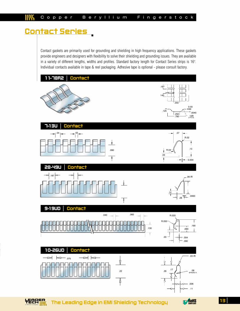
Contact gaskets are primarily used for grounding and shielding in high frequency applications. These gaskets provide engineers and designers with flexibility to solve their shielding and grounding issues. They are available in a variety of different lengths, widths and profiles. Standard factory length for Contact Series strips is 16". Individual contacts available in tape & reel packaging. Adhesive tape is optional - please consult factory.
11-78R2 Contact
9-19UD Contact
7-13U Contact.04 .02 .07
R.04
R.02
.13
.03
0.004
.187
140
.250
.250
.780
0.03
.12R(4 PLCS)
.0045.125
.075
.22
10-26UD Contact
.187
28-49U Contact
.06 IR
.0063
.12
.28
.040 .060
.130
C o p p e r B e r y l l i u m F i n g e r s t o c k
Contact Series
.004
.090
.05 SPHERE R
.004
.05SPHERE R
.04
.30 .34
.38
.08SPHERE R
.05
.006
.38 .31
C o p p e r B e r y l l i u m F i n g e r s t o c k
4-34D Contact
.075
4-38D Contact
.075 .05
.22
.08SPHERE R
.05
.006
.53 .47
4-53D Contact
.093 .062
.31
.09SPHERE R
.78 .66
.010
.045
9-78D Contact 9-78D-A Contact.09
SPHERE R
.78 .66
.010
.09
9˚
14 Order Toll-Free 1.866.TECH.EMI Fax 813.855.3291 Website www.leadertechinc.com
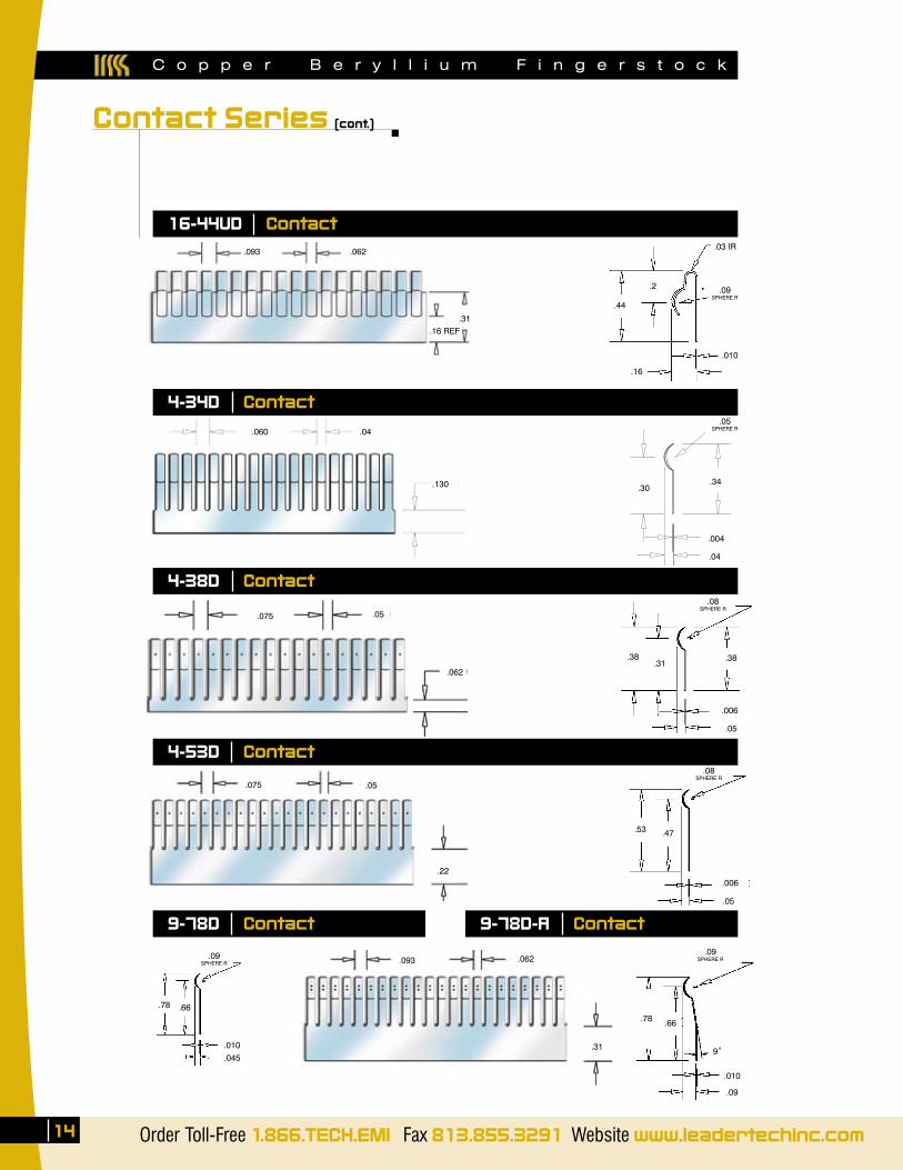
Contact Series (cont.)
.03 IR
.010
.16
.44
.2
.093 .062
.31.16 REF
16-44UD Contact
.130
.04.060
.062
.09SPHERE R
.05
The Leading Edge in EMI Shielding Technology ✔RoHSCOMPLIANT
15
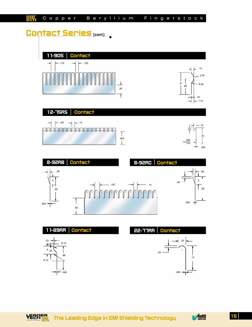
Contact Series (cont.)
.172 .125
.38
.9 .66
.12
.2 IR
R.02
.01
.110
11-90S Contact
12-75RS Contact
.645
.12
.12
.75
.005
.200TRANSFER
TAPE
.187 .14
.77
.05
.23
.005
8-92RB Contact
.09
.3
.92
.005
22-77RR Contact11-89RA Contact
.187 .14
.63
8-92RC Contact
C o p p e r B e r y l l i u m F i n g e r s t o c k
.005
.92
.3.06
.09
.005
R.12 .03
.22
R.12
.3
.89
C o p p e r B e r y l l i u m F i n g e r s t o c k
16 Order Toll-Free 1.866.TECH.EMI Fax 813.855.3291 Website www.leadertechinc.com
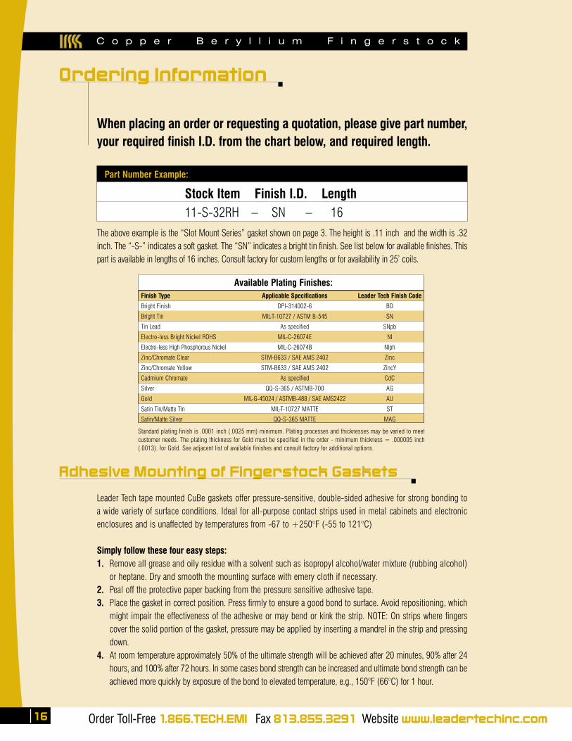
When placing an order or requesting a quotation, please give part number, your required finish I.D. from the chart below, and required length.
Leader Tech tape mounted CuBe gaskets offer pressure-sensitive, double-sided adhesive for strong bonding to a wide variety of surface conditions. Ideal for all-purpose contact strips used in metal cabinets and electronic enclosures and is unaffected by temperatures from -67 to +250°F (-55 to 121°C)
Simply follow these four easy steps:1. Remove all grease and oily residue with a solvent such as isopropyl alcohol/water mixture (rubbing alcohol)
or heptane. Dry and smooth the mounting surface with emery cloth if necessary.2. Peal off the protective paper backing from the pressure sensitive adhesive tape.3. Place the gasket in correct position. Press firmly to ensure a good bond to surface. Avoid repositioning, which
might impair the effectiveness of the adhesive or may bend or kink the strip. NOTE: On strips where fingers cover the solid portion of the gasket, pressure may be applied by inserting a mandrel in the strip and pressing down.
4. At room temperature approximately 50% of the ultimate strength will be achieved after 20 minutes, 90% after 24 hours, and 100% after 72 hours. In some cases bond strength can be increased and ultimate bond strength can be achieved more quickly by exposure of the bond to elevated temperature, e.g., 150°F (66°C) for 1 hour.
Adhesive Mounting of Fingerstock Gaskets
The above example is the “Slot Mount Series” gasket shown on page 3. The height is .11 inch and the width is .32 inch. The “-S-” indicates a soft gasket. The “SN” indicates a bright tin finish. See list below for available finishes. This part is available in lengths of 16 inches. Consult factory for custom lengths or for availability in 25’ coils.
Part Number Example:
Stock Item Finish I.D. Length11-S-32RH – SN – 16
Standard plating finish is .0001 inch (.0025 mm) minimum. Plating processes and thicknesses may be varied to meet customer needs. The plating thickness for Gold must be specified in the order - minimum thickness = .000005 inch (.0013). for Gold. See adjacent list of available finishes and consult factory for additional options.
Available Plating Finishes:
Finish Type Applicable Specifications Leader Tech Finish Code
Bright Finish DPI-314002-6 BD
Bright Tin MIL-T-10727 / ASTM B-545 SN
Tin Lead As specified SNpb
Electro-less Bright Nickel ROHS MIL-C-26074E NI
Electro-less High Phosphorous Nickel MIL-C-26074B NIph
Zinc/Chromate Clear STM-B633 / SAE AMS 2402 Zinc
Zinc/Chromate Yellow STM-B633 / SAE AMS 2402 ZincY
Cadmium Chromate As specified CdC
Silver QQ-S-365 / ASTMB-700 AG
Gold MIL-G-45024 / ASTMB-488 / SAE AMS2422 AU
Satin Tin/Matte Tin MIL-T-10727 MATTE ST
Satin/Matte Silver QQ-S-365 MATTE MAG
Ordering Information

The Leading Edge in EMI Shielding Technology ✔RoHSCOMPLIANT
17
Leader Tech Copper Beryllium gaskets are non-porous, non-hygroscopic, and have a smooth surface. Properly applied, wiping gaskets are inherently self-cleaning and resist oxidation given the absence of moisture. Compression-only gaskets usually have high-pressure contacts, which bind the two surfaces and resists oxidation. However, given enough time, temperature, and other environmental effects all of the metals we use will corrode.
In the presence of oxygen, metals oxidize. Other atmospheric effects and thermal cycling accelerates this pro-cess. When moisture is present, these oxidized salts form electrolytes between the two dissimilar metals and become a simple battery. As currents flow from the cathode to the anode, voltage potentials develop. The voltage amplitude is directly proportional to currents flowing across the junction of the two metals. These currents accelerate corrosion of the metals.
Using Mil-STD 1250, the galvanic potential should not exceed .25 volts. This specification is critical for salt spray or other harsh environments. In commercial applications, many engineers allow up to .5 volts in controlled environments. To reduce the effects of galvanic conditions, we suggest using the following chart to select the correct metals and plating surfaces.
Cathode
Zinc .075
Aluminum 1.05 .029
Cadmium 1.05 .029 0.01
Tin 1.36 .060 0.31 0.31
Iron, Steel 1.30 .029 0.32 0.32 0.01
Chromium 1.39 0.65 0.34 0.34 0.03 0.02
Brass 1.54 0.78 0.500 0.50 0.22 0.20 0.02
Copper, Bronze 1.58 0.82 0.55 0.55 0.24 0.23 0.11 0.02
Nickel, Monel 1.58 0.82 0.56 0.56 0.25 0.25 0.12 0.03 0.01
Stainless Steel 1.67 0.91 0.64 0.64 0.35 0.32 0.20 0.11 0.02 0.08
Silver 1.78 1.02 0.75 0.75 0.44 0.43 0.31 0.22 0.21 0.19 0.11
Anode
Mag
nesi
um
Zinc
Alum
inum
Cadm
ium
Tin
Iron
, Ste
el
Chro
miu
m
Bras
s
Copp
er, B
ronz
e
Nick
el, M
onel
Stai
nles
s St
eel
1. For units which will be subjected to salt spray or salt water, metal should be chosen where the potential difference is less than 0.25V.
2. Where it is possible the unit will be subjected to high humidity that is not salt laden, then the potential difference should not exceed 0.45V.
C o p p e r B e r y l l i u m F i n g e r s t o c k
Metals Galvanic Compatibility Chart
C o p p e r B e r y l l i u m F i n g e r s t o c k
18 Order Toll-Free 1.866.TECH.EMI Fax 813.855.3291 Website www.leadertechinc.com
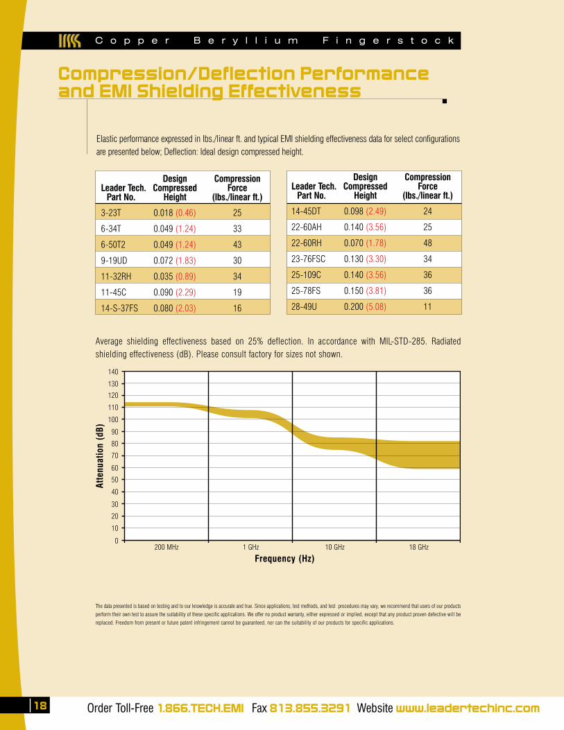
Elastic performance expressed in lbs./linear ft. and typical EMI shielding effectiveness data for select configurations are presented below; Deflection: Ideal design compressed height.
Design Compression Leader Tech. Compressed Force Part No. Height (lbs./linear ft.) 3-23T 0.018 (0.46) 25
6-34T 0.049 (1.24) 33
6-50T2 0.049 (1.24) 43
9-19UD 0.072 (1.83) 30
11-32RH 0.035 (0.89) 34
11-45C 0.090 (2.29) 19
14-S-37FS 0.080 (2.03) 16
Average shielding effectiveness based on 25% deflection. In accordance with MIL-STD-285. Radiated shielding effectiveness (dB). Please consult factory for sizes not shown.
The data presented is based on testing and to our knowledge is accurate and true. Since applications, test methods, and test procedures may vary, we recommend that users of our products
perform their own test to assure the suitability of these specific applications. We offer no product warranty, either expressed or implied, except that any product proven defective will be
replaced. Freedom from present or future patent infringement cannot be guaranteed, nor can the suitability of our products for specific applications.
Atte
nuat
ion
(dB)
140
130
120
110
100
90
80
70
60
50
40
30
20
10
0200 MHz 1 GHz 10 GHz 18 GHz
Frequency (Hz)
Design Compression Leader Tech. Compressed Force Part No. Height (lbs./linear ft.) 14-45DT 0.098 (2.49) 24
22-60AH 0.140 (3.56) 25
22-60RH 0.070 (1.78) 48
23-76FSC 0.130 (3.30) 34
25-109C 0.140 (3.56) 36
25-78FS 0.150 (3.81) 36
28-49U 0.200 (5.08) 11
Compression/Deflection Performanceand EMI Shielding Effectiveness
The Leading Edge in EMI Shielding Technology ✔RoHSCOMPLIANT
519
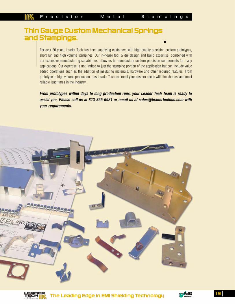
For over 20 years, Leader Tech has been supplying customers with high quality precision custom prototypes, short run and high volume stampings. Our in-house tool & die design and build expertise, combined with our extensive manufacturing capabilities, allow us to manufacture custom precision components for many applications. Our expertise is not limited to just the stamping portion of the application but can include value added operations such as the addition of insulating materials, hardware and other required features. From prototype to high volume production runs, Leader Tech can meet your custom needs with the shortest and most reliable lead times in the industry.
From prototypes within days to long production runs, your Leader Tech Team is ready to assist you. Please call us at 813-855-6921 or email us at [email protected] with your requirements.
P r e c i s i o n M e t a l S t a m p i n g s
Thin Gauge Custom Mechanical Springsand Stampings.
Profile Style Sheet Size Material Code If Conductive Adhesive
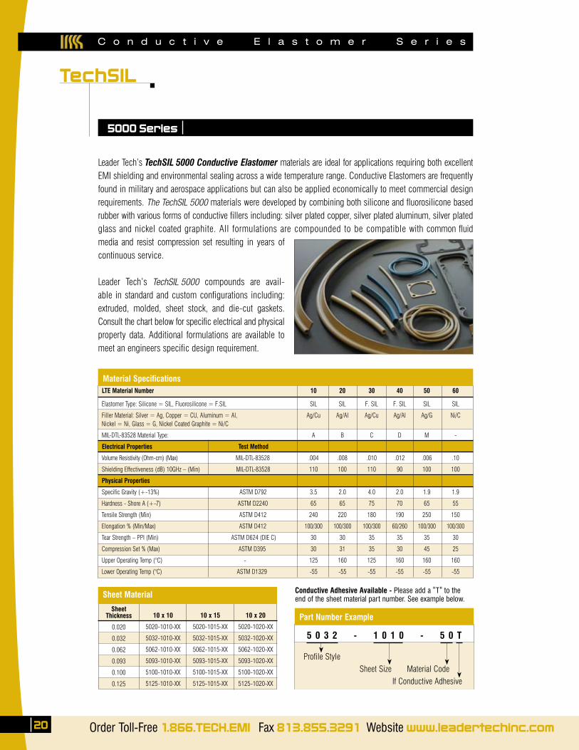
Leader Tech’s TechSIL 5000 Conductive Elastomer materials are ideal for applications requiring both excellent EMI shielding and environmental sealing across a wide temperature range. Conductive Elastomers are frequently found in military and aerospace applications but can also be applied economically to meet commercial design requirements. The TechSIL 5000 materials were developed by combining both silicone and fluorosilicone based rubber with various forms of conductive fillers including: silver plated copper, silver plated aluminum, silver plated glass and nickel coated graphite. All formulations are compounded to be compatible with common fluid media and resist compression set resulting in years of continuous service.
Leader Tech’s TechSIL 5000 compounds are avail-able in standard and custom configurations including: extruded, molded, sheet stock, and die-cut gaskets. Consult the chart below for specific electrical and physical property data. Additional formulations are available to meet an engineers specific design requirement.
TechSIL
20 Order Toll-Free 1.866.TECH.EMI Fax 813.855.3291 Website www.leadertechinc.com
5000 Series
LTE Material Number 10 20 30 40 50 60
Elastomer Type: Silicone = SIL, Fluorosilicone = F.SIL SIL SIL F. SIL F. SIL SIL SIL
Filler Material: Silver = Ag, Copper = CU, Aluminum = Al, Ag/Cu Ag/Al Ag/Cu Ag/Al Ag/G Ni/C Nickel = Ni, Glass = G, Nickel Coated Graphite = Ni/C
MIL-DTL-83528 Material Type: A B C D M -
Electrical Properties Test Method
Volume Resistivity (Ohm-cm) (Max) MIL-DTL-83528 .004 .008 .010 .012 .006 .10
Shielding Effectiveness (dB) 10GHz – (Min) MIL-DTL-83528 110 100 110 90 100 100
Physical Properties
Specific Gravity (+-13%) ASTM D792 3.5 2.0 4.0 2.0 1.9 1.9
Hardness - Shore A (+-7) ASTM D2240 65 65 75 70 65 55
Tensile Strength (Min) ASTM D412 240 220 180 190 250 150
Elongation % (Min/Max) ASTM D412 100/300 100/300 100/300 60/260 100/300 100/300
Tear Strength – PPI (Min) ASTM D624 (DIE C) 30 30 35 35 35 30
Compression Set % (Max) ASTM D395 30 31 35 30 45 25
Upper Operating Temp (°C) - 125 160 125 160 160 160
Lower Operating Temp (°C) ASTM D1329 -55 -55 -55 -55 -55 -55
SheetThickness
0.020
0.032
0.062
0.093
0.100
0.125
10 x 10
5020-1010-XX
5032-1010-XX
5062-1010-XX
5093-1010-XX
5100-1010-XX
5125-1010-XX
10 x 15
5020-1015-XX
5032-1015-XX
5062-1015-XX
5093-1015-XX
5100-1015-XX
5125-1015-XX
10 x 20
5020-1020-XX
5032-1020-XX
5062-1020-XX
5093-1020-XX
5100-1020-XX
5125-1020-XX
Material Specifications
Sheet Material
C o n d u c t i v e E l a s t o m e r S e r i e s
Conductive Adhesive Available - Please add a "T" to the end of the sheet material part number. See example below.
5 0 3 2 - 1 0 1 0 - 5 0 T
Part Number Example
Profile Style 9 if tape required Assigned by Leader Tech Material Code
The Leading Edge in EMI Shielding Technology ✔RoHSCOMPLIANT
TechSIL
21
5000 Series
Part Number
5200-0005-XX
5200-0010-XX
5200-0015-XX
5200-0020-XX
5200-0025-XX
5200-0030-XX
5200-0035-XX
5200-0040-XX
5200-0045-XX
5200-0050-XX
5200-0055-XX
5200-0060-XX
Width (A)
0.063
0.095
0.120
0.125
0.156
0.250
0.500
0.500
0.500
0.750
0.880
1.180
Height (B)
0.042
0.062
0.075
0.062
0.062
0.062
0.075
0.125
0.188
0.062
0.062
0.062
Part Number
5500-0005-XX
5500-0010-XX
5500-0015-XX
5500-0020-XX
5500-0025-XX
5500-0030-XX
5500-0035-XX
5500-0040-XX
5500-0045-XX
5500-0050-XX
5500-09055-XX
5500-0060-XX
(A)
0.031
0.047
0.039
0.047
0.031
0.075
0.061
0.059
0.078
0.89
0.094
0.125
(B)
0.062
0.094
0.078
0.094
0.062
0.150
0.124
0.118
0.156
0.178
0.188
0.250
Part Number
5400-0005-XX
5400-0010-XX
5400-0015-XX
5400-0020-XX
5400-0025-XX
5400-0030-XX
5400-0035-XX
5400-0040-XX
(OD)
0.090
0.103
0.125
0.125
0.156
0.250
0.312
0.375
(ID)
0.050
0.040
0.045
0.062
0.050
0.125
0.192
0.250
(C)
0.068
0.078
0.089
0.094
0.100
0.110
0.136
0.156
0.156
0.175
0.188
0.250
Part Number
5600-0005-XX
5600-0010-XX
5600-0015-XX
5600-0020-XX
5600-0025-XX
5600-0030-XX
(A)
0.156
0.187
0.250
0.312
0.312
0.487
(B)
0.078
0.093
0.125
0.156
0.200
0.324
(C)
0.078
0.093
0.125
0.156
0.112
0.244
(D)
0.045
0.050
0.065
0.062
0.062
0.062
Part Number
5700-0005-XX
5700-0010-XX
5700-0015-XX
5700-0020-XX
5700-0025-XX
5700-0030-XX
5700-0035-XX
5700-0040-XX
(A)
0.200
0.250
0.250
0.250
0.312
0.360
0.200
0.250
(B)
0.080
0.125
0.125
0.150
0.187
0.255
0.080
0.125
(C)
0.650
0.250
0.375
0.375
0.563
0.420
0.275
0.625
(D)
0.062
0.062
0.062
0.062
0.062
0.070
0.062
0.062
Part Number
5800-0005-XX
5800-0010-XX
5800-0015-XX
5800-0020-XX
5800-0025-XX
5800-0030-XX
(A)
0.100
0.126
0.126
0.156
0.175
0.327
(B)
0.100
0.110
0.225
0.156
0.156
0.235
(C)
0.034
0.026
0.020
0.047
0.047
0.062
(D)
0.033
0.050
0.075
0.047
0.075
0.115
Solid Rectangular Strip
Hollow D Strip
Solid D Strip
P Strip Tubing
U Channel Strip
Hollow Round Tubing
C o n d u c t i v e E l a s t o m e r S e r i e s
Part Number
5300-0005-XX
5300-0010-XX
5300-0012-XX
5300-0015-XX
5300-0020-XX
5300-0025-XX
5300-0030-XX
5300-0035-XX
5300-0040-XX
5300-0045-XX
5300-0050-XX
5300-0055-XX
Diameter (D)
0.040
0.062
0.070
0.080
0.093
0.103
0.119
0.125
0.139
0.188
0.216
0.250
Solid Round Strip
5 X X X - 9 X X X - X X
Part Number Example
O r i e n t e d W i r e S e r i e s
TechSIL
22 Order Toll-Free 1.866.TECH.EMI Fax 813.855.3291 Website www.leadertechinc.com
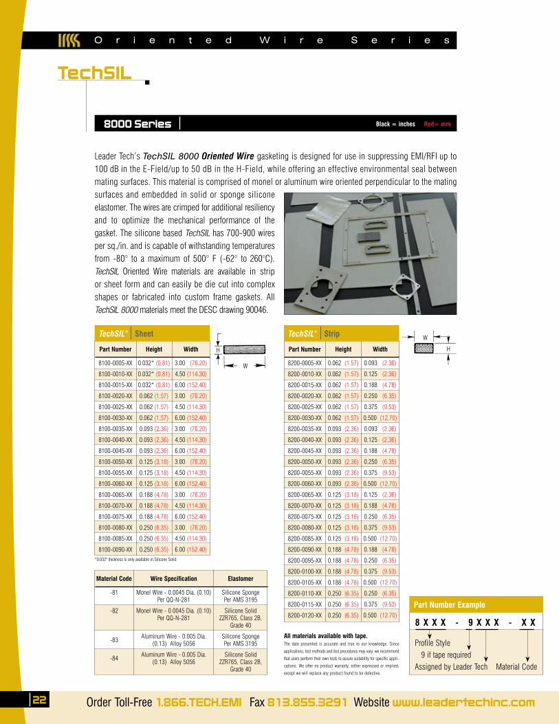
Leader Tech’s TechSIL 8000 Oriented Wire gasketing is designed for use in suppressing EMI/RFI up to 100 dB in the E-Field/up to 50 dB in the H-Field, while offering an effective environmental seal between mating surfaces. This material is comprised of monel or aluminum wire oriented perpendicular to the mating surfaces and embedded in solid or sponge silicone elastomer. The wires are crimped for additional resiliency and to optimize the mechanical performance of the gasket. The silicone based TechSIL has 700-900 wires per sq./in. and is capable of withstanding temperatures from -80° to a maximum of 500° F (-62° to 260°C). TechSIL Oriented Wire materials are available in strip or sheet form and can easily be die cut into complex shapes or fabricated into custom frame gaskets. All TechSIL 8000 materials meet the DESC drawing 90046.
8000 Series
*0.032" thickness is only available in Silicone Solid
H
W
All materials available with tape.The data presented is accurate and true to our knowledge. Since
applications, test methods and test procedures may vary, we recommend
that users perform their own tests to assure suitability for specific appli-
cations. We offer no product warranty, either expressed or implied,
except we will replace any product found to be defective.
Part Number
8100-0005-XX
8100-0010-XX
8100-0015-XX
8100-0020-XX
8100-0025-XX
8100-0030-XX
8100-0035-XX
8100-0040-XX
8100-0045-XX
8100-0050-XX
8100-0055-XX
8100-0060-XX
8100-0065-XX
8100-0070-XX
8100-0075-XX
8100-0080-XX
8100-0085-XX
8100-0090-XX
Height
0.032* (0.81)
0.032* (0.81)
0.032* (0.81)
0.062 (1.57)
0.062 (1.57)
0.062 (1.57)
0.093 (2.36)
0.093 (2.36)
0.093 (2.36)
0.125 (3.18)
0.125 (3.18)
0.125 (3.18)
0.188 (4.78)
0.188 (4.78)
0.188 (4.78)
0.250 (6.35)
0.250 (6.35)
0.250 (6.35)
Width
3.00 (76.20)
4.50 (114.30)
6.00 (152.40)
3.00 (76.20)
4.50 (114.30)
6.00 (152.40)
3.00 (76.20)
4.50 (114.30)
6.00 (152.40)
3.00 (76.20)
4.50 (114.30)
6.00 (152.40)
3.00 (76.20)
4.50 (114.30)
6.00 (152.40)
3.00 (76.20)
4.50 (114.30)
6.00 (152.40)
TechSIL® Sheet
Material Code
-81
-82
-83
-84
Wire Specification
Monel Wire - 0.0045 Dia. (0.10)Per QQ-N-281
Monel Wire - 0.0045 Dia. (0.10)Per QQ-N-281
Aluminum Wire - 0.005 Dia.(0.13) Alloy 5056
Aluminum Wire - 0.005 Dia.(0.13) Alloy 5056
Elastomer
Silicone SpongePer AMS 3195
Silicone SolidZZR765, Class 2B,
Grade 40
Silicone SpongePer AMS 3195
Silicone SolidZZR765, Class 2B,
Grade 40
Part Number
8200-0005-XX
8200-0010-XX
8200-0015-XX
8200-0020-XX
8200-0025-XX
8200-0030-XX
8200-0035-XX
8200-0040-XX
8200-0045-XX
8200-0050-XX
8200-0055-XX
8200-0060-XX
8200-0065-XX
8200-0070-XX
8200-0075-XX
8200-0080-XX
8200-0085-XX
8200-0090-XX
8200-0095-XX
8200-0100-XX
8200-0105-XX
8200-0110-XX
8200-0115-XX
8200-0120-XX
Height
0.062 (1.57)
0.062 (1.57)
0.062 (1.57)
0.062 (1.57)
0.062 (1.57)
0.062 (1.57)
0.093 (2.36)
0.093 (2.36)
0.093 (2.36)
0.093 (2.36)
0.093 (2.36)
0.093 (2.36)
0.125 (3.18)
0.125 (3.18)
0.125 (3.18)
0.125 (3.18)
0.125 (3.18)
0.188 (4.78)
0.188 (4.78)
0.188 (4.78)
0.188 (4.78)
0.250 (6.35)
0.250 (6.35)
0.250 (6.35)
Width
0.093 (2.36)
0.125 (2.36)
0.188 (4.78)
0.250 (6.35)
0.375 (9.53)
0.500 (12.70)
0.093 (2.36)
0.125 (2.36)
0.188 (4.78)
0.250 (6.35)
0.375 (9.53)
0.500 (12.70)
0.125 (2.36)
0.188 (4.78)
0.250 (6.35)
0.375 (9.53)
0.500 (12.70)
0.188 (4.78)
0.250 (6.35)
0.375 (9.53)
0.500 (12.70)
0.250 (6.35)
0.375 (9.53)
0.500 (12.70)
TechSIL® Strip
H
W
Profile Style 9 if tape requiredAssigned by Leader Tech Material Code
8 X X X - 9 X X X - X X
Part Number Example
Black = inches Red= mm
Profile Style 9 if tape requiredAssigned by Leader Tech Material Code
The Leading Edge in EMI Shielding Technology ✔RoHSCOMPLIANT
TechMESH
23
Knitted Wire
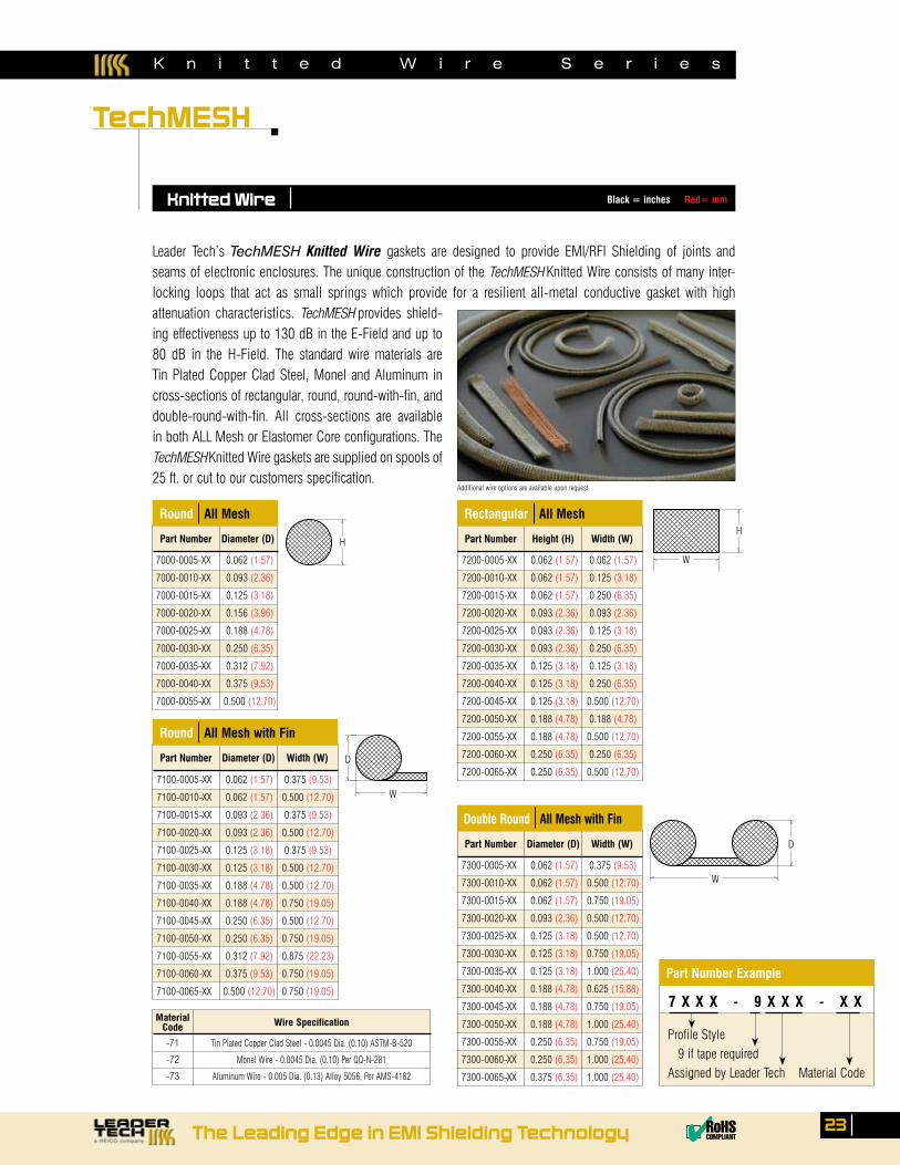
Leader Tech’s TechMESH Knitted Wire gaskets are designed to provide EMI/RFI Shielding of joints and seams of electronic enclosures. The unique construction of the TechMESH Knitted Wire consists of many inter-locking loops that act as small springs which provide for a resilient all-metal conductive gasket with high attenuation characteristics. TechMESH provides shield-ing effectiveness up to 130 dB in the E-Field and up to 80 dB in the H-Field. The standard wire materials are Tin Plated Copper Clad Steel, Monel and Aluminum in cross-sections of rectangular, round, round-with-fin, and double-round-with-fin. All cross-sections are available in both ALL Mesh or Elastomer Core configurations. The TechMESH Knitted Wire gaskets are supplied on spools of 25 ft. or cut to our customers specification.
Additional wire options are available upon request
Part Number Diameter (D)
Round All Mesh
Part Number Height (H) Width (W)
Rectangular All Mesh
Part Number Diameter (D) Width (W)
Double Round All Mesh with Fin
MaterialCode
-71
-72
-73
Wire Specification
Tin Plated Copper Clad Steel - 0.0045 Dia. (0.10) ASTM-B-520
Monel Wire - 0.0045 Dia. (0.10) Per QQ-N-281
Aluminum Wire - 0.005 Dia. (0.13) Alloy 5056, Per AMS-4182
Part Number Diameter (D) Width (W)
Round All Mesh with Fin
H
W
D
D
W
W
H
7000-0005-XX 0.062 (1.57)
7000-0010-XX 0.093 (2.36)
7000-0015-XX 0.125 (3.18)
7000-0020-XX 0.156 (3.96)
7000-0025-XX 0.188 (4.78)
7000-0030-XX 0.250 (6.35)
7000-0035-XX 0.312 (7.92)
7000-0040-XX 0.375 (9.53)
7000-0055-XX 0.500 (12.70)
7200-0005-XX 0.062 (1.57) 0.062 (1.57)
7200-0010-XX 0.062 (1.57) 0.125 (3.18)
7200-0015-XX 0.062 (1.57) 0.250 (6.35)
7200-0020-XX 0.093 (2.36) 0.093 (2.36)
7200-0025-XX 0.093 (2.36) 0.125 (3.18)
7200-0030-XX 0.093 (2.36) 0.250 (6.35)
7200-0035-XX 0.125 (3.18) 0.125 (3.18)
7200-0040-XX 0.125 (3.18) 0.250 (6.35)
7200-0045-XX 0.125 (3.18) 0.500 (12.70)
7200-0050-XX 0.188 (4.78) 0.188 (4.78)
7200-0055-XX 0.188 (4.78) 0.500 (12.70)
7200-0060-XX 0.250 (6.35) 0.250 (6.35)
7200-0065-XX 0.250 (6.35) 0.500 (12.70)
7300-0005-XX 0.062 (1.57) 0.375 (9.53)
7300-0010-XX 0.062 (1.57) 0.500 (12.70)
7300-0015-XX 0.062 (1.57) 0.750 (19.05)
7300-0020-XX 0.093 (2.36) 0.500 (12.70)
7300-0025-XX 0.125 (3.18) 0.500 (12.70)
7300-0030-XX 0.125 (3.18) 0.750 (19.05)
7300-0035-XX 0.125 (3.18) 1.000 (25.40)
7300-0040-XX 0.188 (4.78) 0.625 (15.88)
7300-0045-XX 0.188 (4.78) 0.750 (19.05)
7300-0050-XX 0.188 (4.78) 1.000 (25.40)
7300-0055-XX 0.250 (6.35) 0.750 (19.05)
7300-0060-XX 0.250 (6.35) 1.000 (25.40)
7300-0065-XX 0.375 (6.35) 1.000 (25.40)
7100-0005-XX 0.062 (1.57) 0.375 (9.53)
7100-0010-XX 0.062 (1.57) 0.500 (12.70)
7100-0015-XX 0.093 (2.36) 0.375 (9.53)
7100-0020-XX 0.093 (2.36) 0.500 (12.70)
7100-0025-XX 0.125 (3.18) 0.375 (9.53)
7100-0030-XX 0.125 (3.18) 0.500 (12.70)
7100-0035-XX 0.188 (4.78) 0.500 (12.70)
7100-0040-XX 0.188 (4.78) 0.750 (19.05)
7100-0045-XX 0.250 (6.35) 0.500 (12.70)
7100-0050-XX 0.250 (6.35) 0.750 (19.05)
7100-0055-XX 0.312 (7.92) 0.875 (22.23)
7100-0060-XX 0.375 (9.53) 0.750 (19.05)
7100-0065-XX 0.500 (12.70) 0.750 (19.05)
K n i t t e d W i r e S e r i e s
7 X X X - 9 X X X - X X
Part Number Example
Black = inches Red= mm
E l a s t o m e r C o r e W i r e S e r i e s
TechMESH
24 Order Toll-Free 1.866.TECH.EMI Fax 813.855.3291 Website www.leadertechinc.com
Elastomer Core
Part Number Height (H) Width (W)
Rectangular Elastomer Mesh
Part Number Diameter (D)
Solid Elastomer Mesh
Material Code
-74
-75
-76
-77
-78
-79
Wire Specification
Monel Wire - 0.0045 Dia. (0.10)Per QQ-N-281B
Monel Wire - 0.0045 Dia. (0.10)Per QQ-N-281B
Monel Wire - 0.0045 Dia. (0.10)Per QQ-N-281B
Tin Plated Copper Clad Steel0.0045 Dia. (0.10) ASTM-B-520
Tin Plated Copper Clad Steel0.0045 Dia. (0.10) ASTM-B-520
Tin Plated Copper Clad Steel0.0045 Dia. (0.10) ASTM-B-520
Elastomer
Neoprene Sponge Mil-R-6130B, Type II,
Grade A
Silicone SpongePer AMS 3195
Silicone SolidPer ZZR765, Class 2B,
Grade 40
Neoprene Sponge Mil-R-6130B, Type II,
Grade A
Silicone SpongePer AMS 3195
Silicone SolidPer ZZR765, Class 2B,
Grade 40
Part Number Diameter (D) Width (W)
P-Bulb Elastomer Mesh
Part Number Diameter (D)
Hollow Elastomer Mesh
D
D
D
W
H
W
7400-0005-XX 0.062 (1.57)
7400-0010-XX 0.125 (3.18)
7400-0015-XX 0.188 (4.78)
7400-0020-XX 0.250 (6.35)
7400-0025-XX 0.312 (7.92)
7400-0030-XX 0.375 (9.53)
7400-0035-XX 0.500 (12.70)
7500-0005-XX 0.125 (3.18) 0.125 (3.18)
7500-0010-XX 0.125 (3.18) 0.188 (4.78)
7500-0015-XX 0.125 (3.18) 0.250 (6.35)
7500-0020-XX 0.188 (4.78) 0.188 (4.78)
7500-0025-XX 0.250 (6.35) 0.250 (6.35)
7500-0030-XX 0.250 (6.35) 0.375 (9.53)
7500-0035-XX 0.250 (6.35) 0.500 (12.70)
7500-0040-XX 0.375 (9.53) 0.500 (12.70)
7500-0045-XX 0.500 (12.70) 0.500 (12.70)
7500-0050-XX 0.500 (12.70) 0.750 (19.05)
7600-0005-XX 0.188 (4.78)
7600-0010-XX 0.250 (6.35)
7600-0015-XX 0.375 (9.53)
7600-0020-XX 0.500 (12.70) 7700-0005-XX 0.125 (3.18) 0.500 (12.70)
7700-0010-XX 0.125 (3.18) 0.625 (15.88)
7700-0015-XX 0.125 (3.18) 0.750 (19.05)
7700-0020-XX 0.188 (4.78) 0.500 (12.70)
7700-0025-XX 0.188 (4.78) 0.625 (15.88)
7700-0030-XX 0.188 (4.78) 0.750 (19.05)
7700-0035-XX 0.250 (6.35) 0.500 (12.70)
7700-0040-XX 0.250 (6.35) 0.750 (19.05)
7700-0045-XX 0.250 (6.35) 1.000 (25.40)
7700-0050-XX 0.500 (12.70) 1.000 (25.40)
Mesh Style 9 if tape required Assigned by Leader Tech Material Code
Part Number Example
7 X X X - 9 X X X - X X
Black = inches Red= mm
The Leading Edge in EMI Shielding Technology ✔RoHSCOMPLIANT
TechMESH
25
Combo Strip
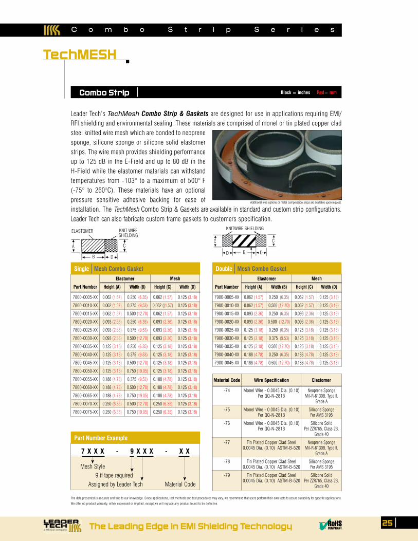
Leader Tech’s TechMesh Combo Strip & Gaskets are designed for use in applications requiring EMI/RFI shielding and environmental sealing. These materials are comprised of monel or tin plated copper clad steel knitted wire mesh which are bonded to neoprene sponge, silicone sponge or silicone solid elastomer strips. The wire mesh provides shielding performance up to 125 dB in the E-Field and up to 80 dB in the H-Field while the elastomer materials can withstand temperatures from -103° to a maximum of 500° F (-75° to 260°C). These materials have an optional pressure sensitive adhesive backing for ease of installation. The TechMesh Combo Strip & Gaskets are available in standard and custom strip configurations. Leader Tech can also fabricate custom frame gaskets to customers specification.
Part Number
7800-0005-XX
7800-0010-XX
7800-0015-XX
7800-0020-XX
7800-0025-XX
7800-0030-XX
7800-0035-XX
7800-0040-XX
7800-0045-XX
7800-0050-XX
7800-0055-XX
7800-0060-XX
7800-0065-XX
7800-0070-XX
7800-0075-XX
Height (A)
0.062 (1.57)
0.062 (1.57)
0.062 (1.57)
0.093 (2.36)
0.093 (2.36)
0.093 (2.36)
0.125 (3.18)
0.125 (3.18)
0.125 (3.18)
0.125 (3.18)
0.188 (4.78)
0.188 (4.78)
0.188 (4.78)
0.250 (6.35)
0.250 (6.35)
Width (B)
0.250 (6.35)
0.375 (9.53)
0.500 (12.70)
0.250 (6.35)
0.375 (9.53)
0.500 (12.70)
0.250 (6.35)
0.375 (9.53)
0.500 (12.70)
0.750 (19.05)
0.375 (9.53)
0.500 (12.70)
0.750 (19.05)
0.500 (12.70)
0.750 (19.05)
Height (C)
0.062 (1.57)
0.062 ((1.57)
0.062 (1.57)
0.093 (2.36)
0.093 (2.36)
0.093 (2.36)
0.125 (3.18)
0.125 (3.18)
0.125 (3.18)
0.125 (3.18)
0.188 (4.78)
0.188 (4.78)
0.188 (4.78)
0.250 (6.35)
0.250 (6.35)
Width (D)
0.125 (3.18)
0.125 (3.18)
0.125 (3.18)
0.125 (3.18)
0.125 (3.18)
0.125 (3.18)
0.125 (3.18)
0.125 (3.18)
0.125 (3.18)
0.125 (3.18)
0.125 (3.18)
0.125 (3.18)
0.125 (3.18)
0.125 (3.18)
0.125 (3.18)
Single Mesh Combo Gasket
The data presented is accurate and true to our knowledge. Since applications, test methods and test procedures may vary, we recommend that users perform their own tests to assure suitability for specific applications.
We offer no product warranty, either expressed or implied, except we will replace any product found to be defective.
Material Code
-74
-75
-76
-77
-78
-79
Wire Specification
Monel Wire - 0.0045 Dia. (0.10)Per QQ-N-281B
Monel Wire - 0.0045 Dia. (0.10)Per QQ-N-281B
Monel Wire - 0.0045 Dia. (0.10)Per QQ-N-281B
Tin Plated Copper Clad Steel0.0045 Dia. (0.10) ASTM-B-520
Tin Plated Copper Clad Steel0.0045 Dia. (0.10) ASTM-B-520
Tin Plated Copper Clad Steel0.0045 Dia. (0.10) ASTM-B-520
Elastomer
Neoprene Sponge Mil-R-6130B, Type II,
Grade A
Silicone SpongePer AMS 3195
Silicone SolidPer ZZR765, Class 2B,
Grade 40
Neoprene Sponge Mil-R-6130B, Type II,
Grade A
Silicone SpongePer AMS 3195
Silicone SolidPer ZZR765, Class 2B,
Grade 40
Additional wire options or metal compression stops are available upon request.
MeshElastomer
Part Number
7900-0005-XX
7900-0010-XX
7900-0015-XX
7900-0020-XX
7900-0025-XX
7900-0030-XX
7900-0035-XX
7900-0040-XX
7900-0045-XX
Height (A)
0.062 (1.57)
0.062 (1.57)
0.093 (2.36)
0.093 (2.36)
0.125 (3.18)
0.125 (3.18)
0.125 (3.18)
0.188 (4.78)
0.188 (4.78)
Width (B)
0.250 (6.35)
0.500 (12.70)
0.250 (6.35)
0.500 (12.70)
0.250 (6.35)
0.375 (9.53)
0.500 (12.70)
0.250 (6.35)
0.500 (12.70)
Height (C)
0.062 (1.57)
0.062 (1.57)
0.093 (2.36)
0.093 (2.36)
0.125 (3.18)
0.125 (3.18)
0.125 (3.18)
0.188 (4.78)
0.188 (4.78)
Width (D)
0.125 (3.18)
0.125 (3.18)
0.125 (3.18)
0.125 (3.18)
0.125 (3.18)
0.125 (3.18)
0.125 (3.18)
0.125 (3.18)
0.125 (3.18)
Double Mesh Combo Gasket
MeshElastomer
A
B
C
D
KNIT WIRESHIELDING
ELASTOMER
B
C
D
KNITWIRE SHIELDING
C
D
C o m b o S t r i p S e r i e s
Mesh Style 9 if tape required Assigned by Leader Tech Material Code
Part Number Example
7 X X X - 9 X X X - X X
Black = inches Red= mm
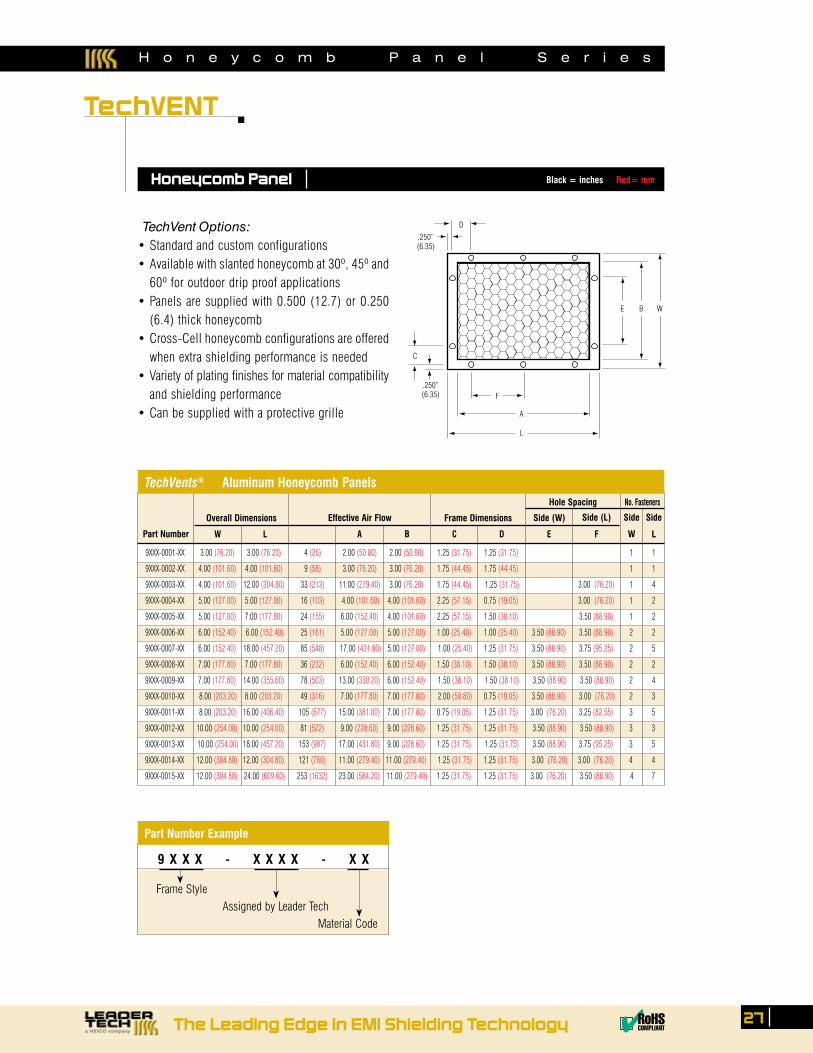
H o n e y c o m b P a n e l S e r i e s
TechVENT
26 Order Toll-Free 1.866.TECH.EMI Fax 813.855.3291 Website www.leadertechinc.com
Honeycomb Panel
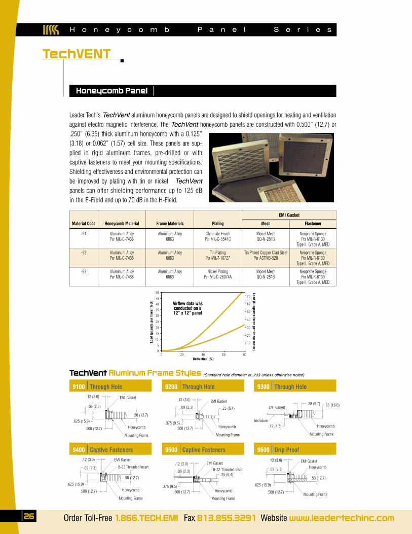
Leader Tech’s TechVent aluminum honeycomb panels are designed to shield openings for heating and ventilation against electro magnetic interference. The TechVent honeycomb panels are constructed with 0.500” (12.7) or .250” (6.35) thick aluminum honeycomb with a 0.125” (3.18) or 0.062” (1.57) cell size. These panels are sup-plied in rigid aluminum frames, pre-drilled or with captive fasteners to meet your mounting specifications. Shielding effectiveness and environmental protection can be improved by plating with tin or nickel. TechVent panels can offer shielding performance up to 125 dB in the E-Field and up to 70 dB in the H-Field.
TechVent Aluminum Frame Styles (Standard hole diameter is .203 unless otherwise noted)
Material Code
-91
-92
-93
Honeycomb Material
Aluminum AlloyPer MIL-C-7438
Aluminum AlloyPer MIL-C-7438
Aluminum AlloyPer MIL-C-7438
Plating
Chromate FinishPer MIL-C-5541C
Tin PlatingPer MIL-T-10727
Nickel PlatingPer MIL-C-26074A
Mesh
Monel MeshQQ-N-281B
Tin Plated Copper Clad SteelPer ASTMB-520
Monel MeshQQ-N-281B
Elastomer
Neoprene SpongePer MIL-R-6130
Type II, Grade A, MED
Neoprene SpongePer MIL-R-6130
Type II, Grade A, MED
Neoprene SpongePer MIL-R-6130
Type II, Grade A, MED
EMI Gasket
Frame Materials
Aluminum Alloy6063
Aluminum Alloy6063
Aluminum Alloy6063
9100 Through Hole
Airflow data wasconducted on a 12” x 12” panel
50
45
40
35
30
25
20
15
10
5
0
70
60
50
40
30
20
10
0 20 40 60 80
Load
(po
unds
per
line
ar f
oot)
Load (kilograms-force per linear m
eter)
Deflection (%)
9200 Through Hole 9300 Through Hole
9400 Captive Fasteners 9500 Captive Fasteners 9600 Drip Proof
.09 (2.3)
.12 (3.0)
.625 (15.9)
.500 (12.7)
EMI Gasket
.50 (12.7)
Honeycomb
Mounting Frame
EMI Gasket
.25 (6.4)
Honeycomb
Mounting Frame
.09 (2.3)
.375 (9.5).500 (12.7)
.12 (3.0).38 (9.7) .63 (16.0)
Honeycomb
Mounting Frame
.19 (4.8)Enclosure
EMI Gasket
Mounting Frame
Honeycomb
.50 (12.7)
EMI Gasket.12 (3.0)
.09 (2.3)
.625 (15.9)
.500 (12.7)
EMI Gasket
Honeycomb
Mounting Frame
.25 (6.4)8-32 Threaded Insert
.12 (3.0)
.09 (2.3)
.375 (9.5).500 (12.7)
.12 (3.0)
.09 (2.3)
.625 (15.9)
.500 (12.7)
Mounting Frame
Honeycomb
.50 (12.7)
8-32 Threaded Insert
EMI Gasket
H o n e y c o m b P a n e l S e r i e s
The Leading Edge in EMI Shielding Technology
TechVENT
27
Honeycomb Panel
TechVent Options:•Standardandcustomconfigurations•Available with slanted honeycomb at 30º, 45º and
60º for outdoor drip proof applications•Panelsaresuppliedwith0.500 (12.7)or0.250
(6.4) thick honeycomb•Cross-Cellhoneycombconfigurationsareoffered
when extra shielding performance is needed•Variety of plating finishes for material compatibility
and shielding performance•Canbesuppliedwithaprotectivegrille
Part Number W L A
Effective Air FlowOverall Dimensions
B C D E F
Side (W)Frame Dimensions
Hole Spacing
Side (L)
No. Fasteners
TechVents® Aluminum Honeycomb Panels
Side
W
Side
L
✔RoHSCOMPLIANT
9XXX-0001-XX 3.00 (76.20) 3.00 (76.20) 4 (26) 2.00 (50.80) 2.00 (50.80) 1.25 (31.75) 1.25 (31.75) 1 1
9XXX-0002-XX 4.00 (101.60) 4.00 (101.60) 9 (58) 3.00 (76.20) 3.00 (76.20) 1.75 (44.45) 1.75 (44.45) 1 1
9XXX-0003-XX 4.00 (101.60) 12.00 (304.80) 33 (213) 11.00 (279.40) 3.00 (76.20) 1.75 (44.45) 1.25 (31.75) 3.00 (76.20) 1 4
9XXX-0004-XX 5.00 (127.00) 5.00 (127.00) 16 (103) 4.00 (101.60) 4.00 (101.60) 2.25 (57.15) 0.75 (19.05) 3.00 (76.20) 1 2
9XXX-0005-XX 5.00 (127.00) 7.00 (177.80) 24 (155) 6.00 (152.40) 4.00 (101.60) 2.25 (57.15) 1.50 (38.10) 3.50 (88.90) 1 2
9XXX-0006-XX 6.00 (152.40) 6.00 (152.40) 25 (161) 5.00 (127.00) 5.00 (127.00) 1.00 (25.40) 1.00 (25.40) 3.50 (88.90) 3.50 (88.90) 2 2
9XXX-0007-XX 6.00 (152.40) 18.00 (457.20) 85 (548) 17.00 (431.80) 5.00 (127.00) 1.00 (25.40) 1.25 (31.75) 3.50 (88.90) 3.75 (95.25) 2 5
9XXX-0008-XX 7.00 (177.80) 7.00 (177.80) 36 (232) 6.00 (152.40) 6.00 (152.40) 1.50 (38.10) 1.50 (38.10) 3.50 (88.90) 3.50 (88.90) 2 2
9XXX-0009-XX 7.00 (177.80) 14.00 (355.60) 78 (503) 13.00 (330.20) 6.00 (152.40) 1.50 (38.10) 1.50 (38.10) 3.50 (88.90) 3.50 (88.90) 2 4
9XXX-0010-XX 8.00 (203.20) 8.00 (203.20) 49 (316) 7.00 (177.80) 7.00 (177.80) 2.00 (50.80) 0.75 (19.05) 3.50 (88.90) 3.00 (76.20) 2 3
9XXX-0011-XX 8.00 (203.20) 16.00 (406.40) 105 (677) 15.00 (381.00) 7.00 (177.80) 0.75 (19.05) 1.25 (31.75) 3.00 (76.20) 3.25 (82.55) 3 5
9XXX-0012-XX 10.00 (254.00) 10.00 (254.00) 81 (522) 9.00 (228.60) 9.00 (228.60) 1.25 (31.75) 1.25 (31.75) 3.50 (88.90) 3.50 (88.90) 3 3
9XXX-0013-XX 10.00 (254.00) 18.00 (457.20) 153 (987) 17.00 (431.80) 9.00 (228.60) 1.25 (31.75) 1.25 (31.75) 3.50 (88.90) 3.75 (95.25) 3 5
9XXX-0014-XX 12.00 (304.80) 12.00 (304.80) 121 (760) 11.00 (279.40) 11.00 (279.40) 1.25 (31.75) 1.25 (31.75) 3.00 (76.20) 3.00 (76.20) 4 4
9XXX-0015-XX 12.00 (304.80) 24.00 (609.60) 253 (1632) 23.00 (584.20) 11.00 (279.40) 1.25 (31.75) 1.25 (31.75) 3.00 (76.20) 3.50 (88.90) 4 7
WBE
D
C
F
A
L
.250”(6.35)
.250”(6.35)
Frame Style Assigned by Leader Tech Material Code
Part Number Example
9 X X X - X X X X - X X
Black = inches Red= mm

E M I M e t a l i z e d F a b r i c S h i e l d i n g G a s k e t s
All dimensions in inches millimeters ±1.6%, or ±0.005” 0.13 mm minimum
28 Order Toll-Free 1.866.TECH.EMI Fax 813.855.3291 Website www.leadertechinc.com
Shielding gaskets are, very simply, connectors of two opposing metallic planes which make them appear as one continuous surface, or RFI absorber, by connecting across the openings. Depending on the frequencies involved, the openings must be reduced as closely as possible to a continuous seal (see “Minimizing the Effects of Openings”).
Leader Tech’s unique fabric shielding gasket structure combines the best features of the two materials used namely, all-around silicone core performance, long life and cost-effectiveness; and the highly conductive outer metalized membrane – all versions universally applicable with common metal mating surfaces.
When access panels, doors, ventilation, displays, etc. are required in an otherwise solid enclosure, precautions must be taken to eliminate the transmission of radio frequencies through such openings or slots. The shielding effectiveness of an enclosure is a function of the wavelength of the frequencies involved versus the length of the longest dimension of openings. One common example is the seam opening occurring between the door and the sash of an electronic cabinet. If the mating seams of a shield form a slot, the slot is the analog of a dipole antenna. One-half wavelength apertures make excellent radiators, but shorter lengths radiate also. The longest dimension of an opening is the most critical (slot length, diagonal of a rectangle, diameter of a circle, etc.). Shielding gaskets are very low resistance connectors of mating surfaces which, when installed, make the surfaces appear as one continuous plane. The graph below displays the maximum shielding effectiveness possible from a given size opening in an enclosure.
It can be seen from the information above that the shielding effectiveness increases as the size of the opening is reduced. In order to achieve the same performance as a small opening, the slot must be coupled electri-cally across its opposing surfaces. This can be accomplished by using conductive fasteners or gaskets. Gaskets are usually the most common choice. They offer a continuous coupling along the full length of the slot while permitting the opposing surfaces to be separated easily for access to the components contained within. See examples in photos.
EMI Shielding Gaskets for Electronic Enclosures
Excellent Shielding Performance
150
100
50
0
10.0 meters (394")
1.0 meter (40")
0.10 meter (4")
0.01 meter (.4") Example: for 0.4 inch opening FREQUENCY S.E. (dB)
1 MHz 83.5 10 MHz 63.5 100 MHz 43.51000 MHz 23.5
Minimizing the Effects of openings
Extremely High Fatigue Resistance
Atte
nuat
ion
(dB)
140
12010080
20
1M 10M 100M 1G0
4060 MEASURED AT 25%
DEFLECTION THROUGHDYNAMIC RANGE
220
200
100
10 10 10 10 101
4 5 6 7 8
Frequency (Hz) Fatigue Cycles
Stre
ss A
mpl
itude
(KS
I)
Shielding Effectiveness Fatigue Life
Typical EMI shielding gasket electronicenclosure installation.
Shielding gaskets assure tight EMIelectrical contact sealing of electronicenclosures with high speed microprocessors.
Shie
ldin
g Ef
fect
iven
ess
(db)
Shielding Effectiveness vs. Frequency as aFunction of Slot Length
Leader Tech EMI fabric gaskets are a combination of a resilient inner core with optimum compression and aging properties, and a metalized conductive outer layer with excellent conductive properties. The unique combination minimizes the costly conductive materials required leaving the balance of the body structure to be made from pure silicone rubber; the result – very high structural properties and very high conductivity and shielding properties. Typical performance characteristics are shown following:
Performance
Top view of electronic enclosure door withtypical shielding gasket installation.
Applications
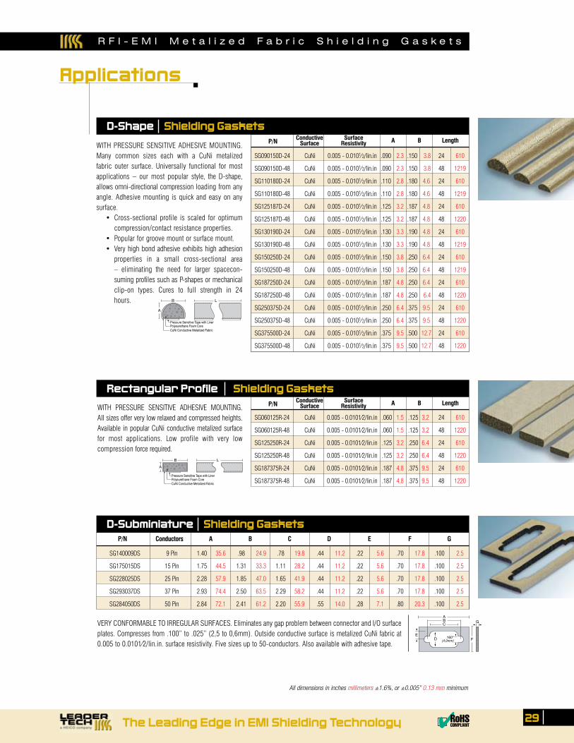
R F I - E M I M e t a l i z e d F a b r i c S h i e l d i n g G a s k e t s
The Leading Edge in EMI Shielding Technology 29✔RoHSCOMPLIANT
WITH PRESSURE SENSITIVE ADHESIVE MOUNTING. Many common sizes each with a CuNi metalized fabric outer surface. Universally functional for most applications – our most popular style, the D-shape, allows omni-directional compression loading from any angle. Adhesive mounting is quick and easy on any surface. •Cross-sectional profile is scaled for optimum
compression/contact resistance properties. •Popularforgroovemountorsurfacemount. •Very high bond adhesive exhibits high adhesion
properties in a small cross-sectional area – eliminating the need for larger spacecon-suming profiles such as P-shapes or mechanical clip-on types. Cures to full strength in 24 hours.
SG090150D-24 CuNi 0.005 - 0.0101⁄2/lin.in .090 2.3 .150 3.8 24 610
SG090150D-48 CuNi 0.005 - 0.0101⁄2/lin.in .090 2.3 .150 3.8 48 1219
SG110180D-24 CuNi 0.005 - 0.0101⁄2/lin.in .110 2.8 .180 4.6 24 610
SG110180D-48 CuNi 0.005 - 0.0101⁄2/lin.in .110 2.8 .180 4.6 48 1219
SG125187D-24 CuNi 0.005 - 0.0101⁄2/lin.in .125 3.2 .187 4.8 24 610
SG125187D-48 CuNi 0.005 - 0.0101⁄2/lin.in .125 3.2 .187 4.8 48 1220
SG130190D-24 CuNi 0.005 - 0.0101⁄2/lin.in .130 3.3 .190 4.8 24 610
SG130190D-48 CuNi 0.005 - 0.0101⁄2/lin.in .130 3.3 .190 4.8 48 1219
SG150250D-24 CuNi 0.005 - 0.0101⁄2/lin.in .150 3.8 .250 6.4 24 610
SG150250D-48 CuNi 0.005 - 0.0101⁄2/lin.in .150 3.8 .250 6.4 48 1219
SG187250D-24 CuNi 0.005 - 0.0101⁄2/lin.in .187 4.8 .250 6.4 24 610
SG187250D-48 CuNi 0.005 - 0.0101⁄2/lin.in .187 4.8 .250 6.4 48 1220
SG250375D-24 CuNi 0.005 - 0.0101⁄2/lin.in .250 6.4 .375 9.5 24 610
SG250375D-48 CuNi 0.005 - 0.0101⁄2/lin.in .250 6.4 .375 9.5 48 1220
SG375500D-24 CuNi 0.005 - 0.0101⁄2/lin.in .375 9.5 .500 12.7 24 610
SG375500D-48 CuNi 0.005 - 0.0101⁄2/lin.in .375 9.5 .500 12.7 48 1220
P/N Conductive Surface A B Length Surface Resistivity
D-Shape Shielding Gaskets
WITH PRESSURE SENSITIVE ADHESIVE MOUNTING. All sizes offer very low relaxed and compressed heights. Available in popular CuNi conductive metalized surface for most applications. Low profile with very low compression force required.
SG060125R-24 CuNi 0.005 - 0.0101⁄2/lin.in .060 1.5 .125 3.2 24 610
SG060125R-48 CuNi 0.005 - 0.0101⁄2/lin.in .060 1.5 .125 3.2 48 1220
SG125250R-24 CuNi 0.005 - 0.0101⁄2/lin.in .125 3.2 .250 6.4 24 610
SG125250R-48 CuNi 0.005 - 0.0101⁄2/lin.in .125 3.2 .250 6.4 48 1220
SG187375R-24 CuNi 0.005 - 0.0101⁄2/lin.in .187 4.8 .375 9.5 24 610
SG187375R-48 CuNi 0.005 - 0.0101⁄2/lin.in .187 4.8 .375 9.5 48 1220
P/N Conductive Surface A B Length Surface Resistivity
Rectangular Profile Shielding Gaskets
B LA
Pressure Sensitive Tape with LinerPolyeurethane Foam CoreCuNi Conductive Metalized Fabric
F
G
ED
CBA
.160"(4,0mm)
D-Subminiature Shielding Gaskets
VERY CONFORMABLE TO IRREGULAR SURFACES. Eliminates any gap problem between connector and I/O surface plates. Compresses from .100” to .025” (2,5 to 0,6mm). Outside conductive surface is metalized CuNi fabric at 0.005 to 0.0101⁄2/lin.in. surface resistivity. Five sizes up to 50-conductors. Also available with adhesive tape.
SG140009DS 9 Pin 1.40 35.6 .98 24.9 .78 19.8 .44 11.2 .22 5.6 .70 17.8 .100 2.5
SG175015DS 15 Pin 1.75 44.5 1.31 33.3 1.11 28.2 .44 11.2 .22 5.6 .70 17.8 .100 2.5
SG228025DS 25 Pin 2.28 57.9 1.85 47.0 1.65 41.9 .44 11.2 .22 5.6 .70 17.8 .100 2.5
SG293037DS 37 Pin 2.93 74.4 2.50 63.5 2.29 58.2 .44 11.2 .22 5.6 .70 17.8 .100 2.5
SG284050DS 50 Pin 2.84 72.1 2.41 61.2 2.20 55.9 .55 14.0 .28 7.1 .80 20.3 .100 2.5
P/N Conductors A B C D E F G
All dimensions in inches millimeters ±1.6%, or ±0.005” 0.13 mm minimum
Applications
B L
A
Pressure Sensitive Tape with LinerPolyeurethane Foam CoreCuNi Conductive Metalized Fabric

R F I - E M I S h i e l d i n g F a b r i c s
A high performance, cost-effective sheet shielding material. Very good electrical and thermal conductivity, high reflectivity and resistance to oxidation and corrosive environments. Composition is a four-layermatrix of static dissipative-EMC coating/polyester/Aluminum/polyethylene. •EMC,ESDcompatibility •Smallcomponenttolargearchitecturalshieldinguses •Availableinsinglesheetsorfullrolls;*Availablein600’(182M)rolls
30 Order Toll-Free 1.866.TECH.EMI Fax 813.855.3291 Website www.leadertechinc.com
Shielding effectiveness is determined by a combination of two events: reflection and absorption of RF signals. Absorption depends on the bulk, or thickness, of the shield material. However, reflection occurs at the shield surface and its effectiveness is independent of thickness. Reflection is the deter-mining factor for all high frequency signal attenuation. (Note: When these materials are used in another regime; i.e., conductive shielding gaskets, conductivity is the determinant.)
Maximum reflection occurs with the highest conductivity materials. The best overall metals are copper, nickel and combinations of both - based on high conductivity, compatibility with mating metals, manu-facturing versatility and cost. The large 41.0” material width (1040mm) minimizes seams; thin .003” - .004” cross sections (0,08 - 0,10mm) maximize conformability to irregular surfaces.
Applications •Bondingor laminating tocomplexgeometricshapes(includesoptionalhotmeltadhesive,or
conductive adhesive backing) •Largesurfacecoveragewithminimalseamsdueto41.0”materialwidth(1040,0mm) •ESD,RFI-EMI;shieldingattenuation>70.0dBupto10.0GHzforCuNitype. •Enclosurepanelsandframes,seams,joints,shieldcurtainsforbackpanelopenings •RFI-EMI conductive shielding gasket cover membranes (i.e., with foam or silicone core structures) •Architecturalshielding;shieldedroomfinishing-ceilings,walls,floors;specialpurposerooms
Options •Allmaterialsareavailableinnon-adhesive,hotmeltadhesiveorconductiveadhesivebacking •Standardsheetsare41”x36”(1040,0x914,0mm) • Longerlengthsmaybeorderedbyaddingasuffix“X”toanypart#withqualifier;i.e.,X=73”(1854,0mm) •Full rolls are 325’-0 long (100M), and can be ordered by specifying the suffix “X” with qualifier; i.e., X = 325’ roll (100M). Note:
conductive adhesive versions are 164’ (50M) long.
Components
Equipment, architectural
RFI-EMI Conductive Shielding Fabrics
SF005PCN SF005PCN-HM SF005PCN-CA Polyester Cloth w/CuNi 41 1041 36 914 0.003 0.09 .005 ohm/mm2 79 81 86 82
SF030PCU SF030PCU-HM SF030PCU-CA Polyester Cloth w/Cu 41 1041 36 914 0.003 0.08 .030 ohm/mm2 60 67 65 62
SF050PNI SF050PNI-HM SF050PNI-CA Polyester Cloth w/Ni 41 1041 36 914 0.004 0.10 .050 ohm/mm2 60 72 67 63
Part No. w/Hot Melt w/Conductive Description Width Length Thickness Surface Attenuation Adhesive Adhesive Resistivity 500KHz 100MHz 300MHz 1GHz
RFI-EMI Shielding Aluminum Sheets
SF100PAL Polyester w/AL 36 914.40 41 1041.40 0.002 0.07 48 65 65 60
Attenuation (dB) PART No. Description Width Length* Thickness 500KHz 100MHz 300MHz 1GHz
All dimensions in inches millimeters ±1.6%, or ±0.005” 0.13 mm minimum
Applications
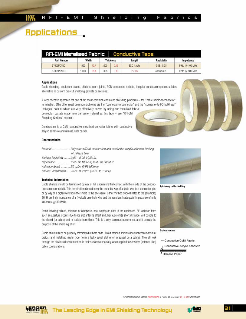
R F I - E M I S h i e l d i n g F a b r i c s
ApplicationsCable shielding, enclosure seams, shielded room joints, PCB component shields, irregular surface/component shields, alternative to custom die-cut shielding gaskets or sections.
A very effective approach for one of the most common enclosure shielding problems – the “cable shield-toconnector” termination. (The other most common problems are the “connector-to connector” and the “connector-to I/O bulkhead” leakages, both of which are very effectively solved by using our metalized fabric connector gaskets made from the same material as this tape – see “RFI-EMI Shielding Gaskets” section.)
Construction is a CuNi conductive metalized polyester fabric with conductive acrylic adhesive and release liner backer.
Characteristics
Material .......................Polyester w/CuNi metalization and conductive acrylic adhesive backing w/ release linerSurface Resistivity ........0.03 - 0.05 1⁄2/lin.in.Impedance ...................69dB @ 100MHz; 62dB @ 500MHzAdhesion (peel) ............50 oz/in. (54N/100mm)Service Temperature .....-40°F to 212°F (-40°C to 100°C)
Technical InformationCable shields should be terminated by way of full circumferential contact with the inside of the conduc-tive connector shield. This termination should never be done by way of a drain wire to a connector pin, or by way of a pigtail wire from the shield to the enclosure. Either method subordinates to the (example) 20nH per inch inductance of a (typical) one-inch wire and the resultant inadequate impedance of only 40 ohms @ 300MHz.
Avoid locating cables, shielded or otherwise, near seams or slots in the enclosure. RF radiation from such an aperture occurs due to its slot antenna effect and, because of its short distance, will couple to the shield (or cable) and re-radiate from there. This is a very common occurrence, and it defeats the purpose of the shielding effort.
Cable shields must be properly terminated at both ends. Avoid braided shields (leak between individual braids) and metalized mylar type (form a leaky spiral slot when wrapped on a cable). They all leak through the obvious discontinuation in their surfaces especially when applied to sensitive (antenna-like) cable configurations.
Release Paper
Conductive CuNi Fabric
Conductive Acrylic Adhesive
Spiral-wrap cable shielding
Enclosure seams
RFI-EMI Metalized Fabric Conductive Tape
ST005PCN50 .500 12.7 .005 0.13 85.0 ft. rolls 0.03 - 0.05 69db @ 100 MHz
ST005PCN100 1.000 25.4 .005 0.13 25.0m ohms/lin.in. 62db @ 500 MHz
Part Number Width Thickness Length Resistivity Impedance
The Leading Edge in EMI Shielding Technology 31✔RoHSCOMPLIANT
All dimensions in inches millimeters ±1.6%, or ±0.005” 0.13 mm minimum
Applications
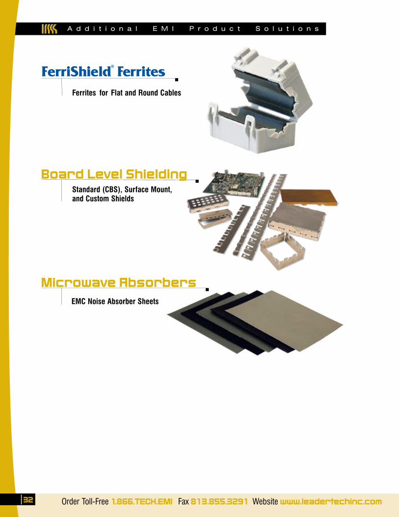
A d d i t i o n a l E M I P r o d u c t S o l u t i o n s
32 Order Toll-Free 1.866.TECH.EMI Fax 813.855.3291 Website www.leadertechinc.com
Ferrites for Flat and Round Cables
Microwave AbsorbersEMC Noise Absorber Sheets
Board Level ShieldingStandard (CBS), Surface Mount, and Custom Shields
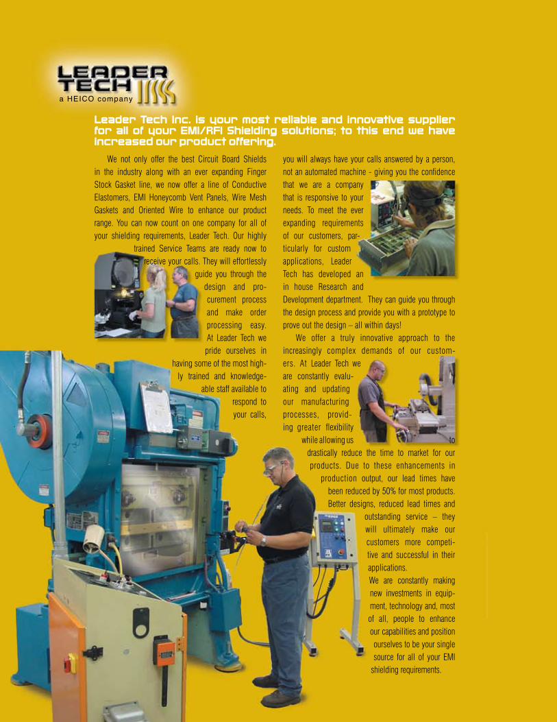
We not only offer the best Circuit Board Shields in the industry along with an ever expanding Finger Stock Gasket line, we now offer a line of Conductive Elastomers, EMI Honeycomb Vent Panels, Wire Mesh Gaskets and Oriented Wire to enhance our product range. You can now count on one company for all of your shielding requirements, Leader Tech. Our highly
trained Service Teams are ready now to receive your calls. They will effortlessly
guide you through the design and pro-curement process and make order processing easy. At Leader Tech we pride ourselves in
having some of the most high-ly trained and knowledge-
able staff available to respond to your calls,
you will always have your calls answered by a person, not an automated machine - giving you the confidence that we are a company that is responsive to your needs. To meet the ever expanding requirements of our customers, par-ticularly for custom applications, Leader Tech has developed an in house Research and Development department. They can guide you through the design process and provide you with a prototype to prove out the design – all within days! We offer a truly innovative approach to the increasingly complex demands of our custom-ers. At Leader Tech we are constantly evalu-ating and updating our manufacturing processes, provid-ing greater flexibility
while allowing us to drastically reduce the time to market for our products. Due to these enhancements in
production output, our lead times have been reduced by 50% for most products. Better designs, reduced lead times and
outstanding service – they will ultimately make our customers more competi-tive and successful in their applications.We are constantly making new investments in equip-ment, technology and, most of all, people to enhance our capabilities and position ourselves to be your single source for all of your EMI
shielding requirements.
Leader Tech Inc. is your most reliable and innovative supplier for all of your EMI/RFI Shielding solutions; to this end we have increased our product offering.
Order Toll-Free 1.866.TECH.EMI Fax 813.855.3291 Website www.leadertechinc.com
a HEICO Company
12420 Race Track RoadTampa, Florida 33626
1-866-TECH-EMI • 813.855.6921Fax: 813.855.3291
www.leadertechinc.com ✔RoHSCOMPLIANT
ISO 9000CERTIFIED
PRE05-01