Embed Size (px)
Citation preview
5 Hydroelectric Power
Archimedes was a mathematician and inventor from ancient Greece (born 280 BC). He invented a screw-shaped machine or hydraulic screw that raised water from a lower to a higher level.
mywbut.com
1
5.1 Introduction
Hydraulic Turbines are used for converting the potential energy of water into useful Mechanical power to drive machines as in Mills or pumps or electrical energy using electrical generators.
• Hydroelectric power stations can be classified according to power output into micro hydro, mini hydro, small hydro and large hydro systems. The definitions according to the International Energy Association are as folloMicro hydro - hydroelectric station with installed capacity lower than 100 kW
• Mini hydro - hydroelectric station in the range of 100kW to 1 MW• Small hydro - hydroelectric station in the range of 1 MW to 30 MW • Large hydro - hydroelectric station with installed capacity of over 30 MW
Hydropower is a clean and renewable source of energy that can contribute to fighting climate change. The following advantages make hydropower a much preferred option to any fossil fuel power scheme:
• No fuel needed - The chief advantage of hydro systems is elimination of the cost of fuel. Hydroelectric plants are immune to price increases for fossil fuels such as oil, natural gas or coal, and do not require imported fuel.
• Longevity - Hydroelectric plants tend to have longer lives than fuel-fired generation, with some plants now in service having been built 50 to 100 years ago.
• Pollution free - Hydroelectric plants generally have small to negligible emissions of carbon dioxide and methane due to reservoir emissions, and emit no sulphur dioxide, nitrogen oxides, dust, or other pollutants associated with combustion.
• Quick Response - Since the generating units can be started and stopped quickly, they can follow system loads efficiently, and may be able to reshape water flows to more closely match daily and seasonal system energy demands.
• Environmentally friendly - Reservoirs created by hydroelectric schemes often provide excellent leisure facilities for water sports, and become tourist attractions in themselves..
• Wildlife preserves can be created around reservoirs, which can provide stable habitats for endangered and threatened species(Eg. catch rates for game fish like walleye and small mouth bass are substantially higher on hydro power reservoirs than natural lakes.)
• Flood prevention – the surplus water can be stored behind the dam and hence reduce the risk of flood.
5.2 Types of hydraulic turbines
Depending on the method of interaction between the fluid and the machine, there are two main types of turbines, IMPULSE and REACTION.
mywbut.com
2

A Impulse Turbine
This type of turbine is usually selected for high head and low flow rate conditions. The water is usually directed on to the turbine blades via a nozzle and the jet will impinge and leaves the turbine at atmospheric condition.The high velocity jet leaves the nozzle at atmospheric pressure and impinges on to the wheel blades or buckets.The tangential force exerted on the buckets is produced by a change in momentum of the jet, both in magnitude and direction.The most important type of impulse turbine is the PELTON wheel.
Figure 5.1: Pelton Turbine (Wheel) Courtesy of: http://re.emsd.gov.hk/english/other/hydroelectric/hyd tech.html#
B Reaction Turbine
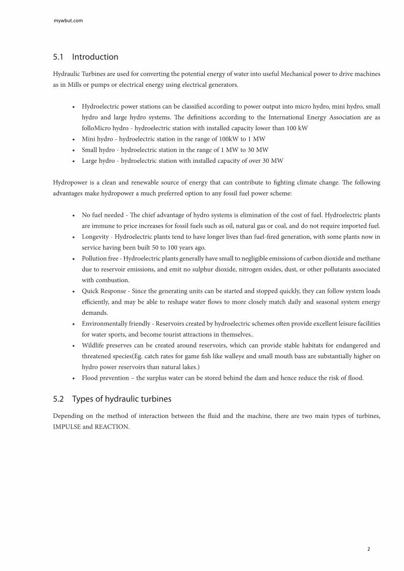
This type of turbine is usually selected for low head conditions, but relatively higher flow rate than in impulse turbines. In reaction turbines part of the pressure energy is transformed into kinetic energy in the stationary guide vanes and the remainder is transferred in the runner wheel. This type of turbine does not run at atmospheric; in fact the pressure changes continuously while flowing through the machine. The chief turbines of this type are the FRANCIS and KAPLAN turbines.
Figure 5.2: Francis Turbine Courtesy of: http://re.emsd.gov.hk/english/other/hydroelectric/hyd tech.html#
mywbut.com
3
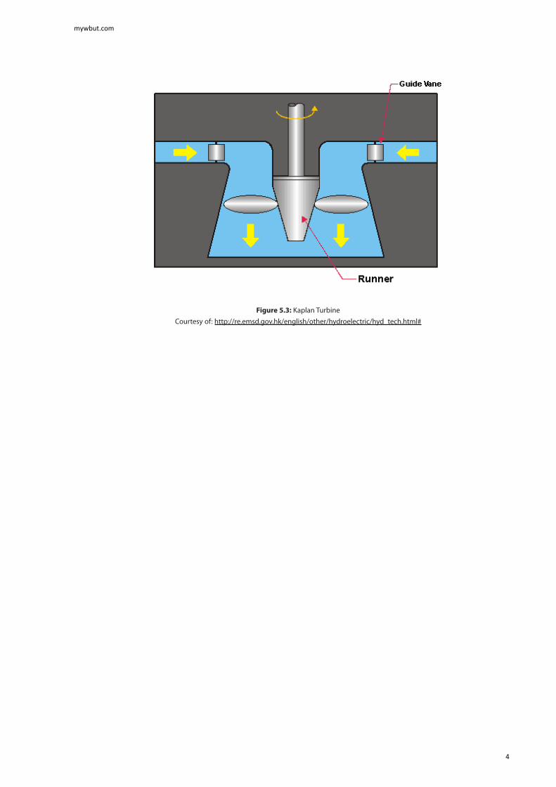
Figure 5.3: Kaplan Turbine Courtesy of: http://re.emsd.gov.hk/english/other/hydroelectric/hyd_tech.html#
mywbut.com
4

C Reversible Pump/Turbine
Modern pumped storage units require the use of a reversible pump / turbine that can be run in one direction as pump and in the other direction as turbine. These are coupled to reversible electric motor/generator. The motor drives the pump during the storage portion of the cycle, while the generator produces electricity during discharge from the upper reservoir.
Most reversible-pump turbines are of the Francis type. The complexity of the unit, however, increases significantly as compared to a turbine alone. In spite of the higher costs for both hydraulic and electrical controls and support equipment, the total installed cost will be less than for completely separate pump-motor and turbine-generator assemblies with dual water passages.
Figure 5.4: Reversible Francis Turbine/Pump system Courtesy of: http://oei.fme.vutbr.cz/jskorpik/en_lopatkovy-stroj.html
mywbut.com
5

5.3 Performance evaluation of Hydraulic Turbines
The power available from water can be expressed as
P = ρ Q g h x η (5.1)
Where
P = power available (W)ρ = density (kg/m3) (~ 1000 kg/m3 for water)Q= water flow (m3/s)g = acceleration of gravity (9.81 m/s2)h = falling height, head (m)
The hydraulic efficiency depends on many factors such as the type of turbine and the operational conditions. Typical values are between 50% and 75%.
The theoretical approach velocity of water is given by:
hgV ..2= (5.2)
However real hydropower stations have penstock of considerable length incorporating many pipe fittings, bends and valves, hence the effective head is reduced, and as such the real velocity of water approaching the turbine is less than that quoted in equation 5.2.
The volume flow rate of water is calculated by the continuity equation:
Q = V x A (5.3)
The different hydraulic turbines described in the previous section have different characteristics such as power rating, operating head and rotational speed, the term specific speed is introduced to group the three terms:
(5.4)
The concept of specific speed helps to classify the different turbines according to the range in which they operate, see Table 5.5.
mywbut.com
6
Figure 5.5 Typical Power – flow rate evaluation chart. Courtesy of: http://www.engineeringtoolbox.com/hydropower-d 1359.html
Type Of Turbine
Specific speed range
Francis 70 – 500
Propeller 600 – 900
Kaplan 350 – 1000
Cross-flow 20 – 90
Turgo 20 – 80
Pelton, 1-jet 10 – 35
Pelton, 2-jet 10 – 45
Table 5.1: Operating Range of Hydraulic Turbines
mywbut.com
7

5.4 Pumped storage hydroelectricity
Some areas of the world have used geographic features to store large quantities of water in elevated reservoirs, using excess electricity at times of low demand to pump water up to the reservoirs, then letting the water fall through turbine generators to retrieve the energy when demand peaks.
Pumped storage hydroelectricity was first used in Italy and Switzerland in the 1890’s. By 1933 reversible pump-turbines with motor-generators were available. Adjustable speed machines are now being used to improve efficiency.
Hydro-electric power plants are economically viable because of the difference between peak and off-peak electricity prices. Pumped-storage plants can respond to load changes within seconds.
Hydropower electricity is the product of transforming the potential energy stored in water in an elevated reservoir into the kinetic energy of the running water, then mechanical energy in a rotating turbine, and finally electrical energy in an alternator or generator. Hydropower is a mature renewable power generation technology that offers two very desirable characteristics in today’s electricity systems: built-in storage that increases the system’s flexibility and fast response time to meet rapid or unexpected fluctuations in supply or demand. Hydropower amounted to 65 % of the electricity generated from renewable energy sources in Europe in 2007 or 9 % of the total electricity production in the EU-27. Today’s installed capacity in the EU-27 for hydropower is about 102 GW, without hydro-pumped storage. Approximately 90 % of this potential is covered by large hydropower plants. Over 21 000 small hydropower plants account for above 12 GW of installed capacity in the EU-27.
Figure 5.6 Typical daily cycle for a pumped storage hydro-electric power plant.
mywbut.com
8

Case study – Dinorwig power station
Dinorwig is the largest scheme of its kind in Europe. The station’s six powerful generating units (6x288 =1728 MW) stand in Europe’s largest man-made cavern. Adjacent to this lies the main inlet valve chamber housing the plant that regulates the flow of water through the turbines.
Dinorwig’s reversible pump/turbines are capable of reaching maximum generation in less than 16 seconds. Using off-peak electricity the six units are reversed as pumps to transport water from the lower reservoir Llyn Peris, back to Marchlyn Mawr.
mywbut.com
9
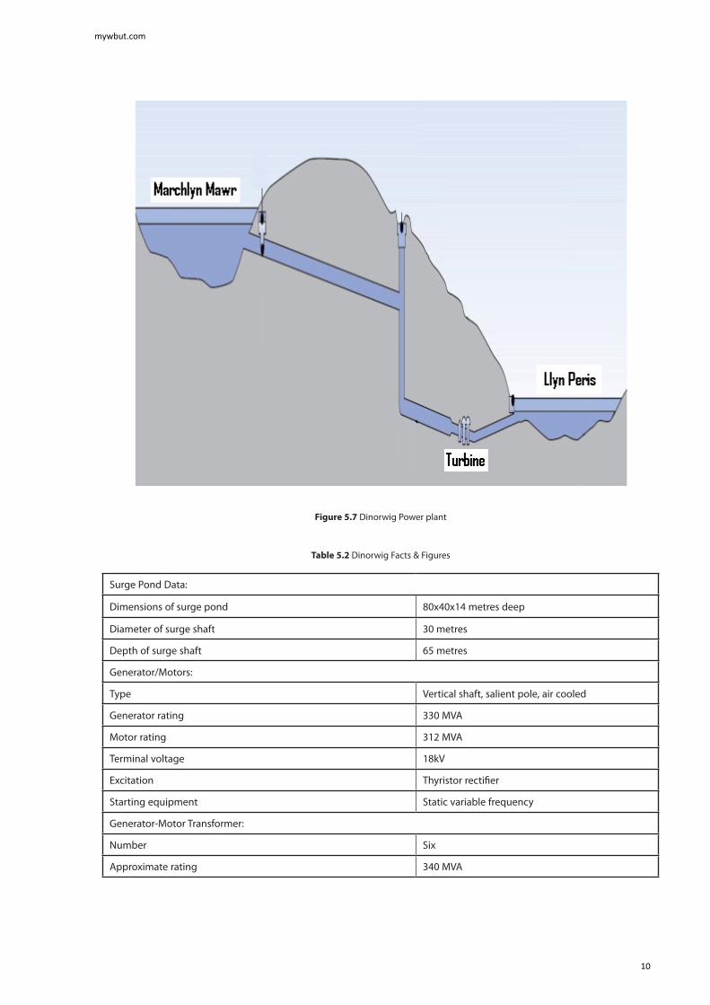
Figure 5.7 Dinorwig Power plant
Table 5.2 Dinorwig Facts & Figures
Surge Pond Data:
Dimensions of surge pond 80x40x14 metres deep
Diameter of surge shaft 30 metres
Depth of surge shaft 65 metres
Generator/Motors:
Type Vertical shaft, salient pole, air cooled
Generator rating 330 MVA
Motor rating 312 MVA
Terminal voltage 18kV
Excitation Thyristor rectifier
Starting equipment Static variable frequency
Generator-Motor Transformer:
Number Six
Approximate rating 340 MVA
mywbut.com
10

Voltage ratio 18 kV/420 kV
Underground Caverns:
Distance of power station inside mountain 750 metres
Depth of turbine hall below top level of Llyn Peris 71 metres
Machine Hall:
Length 180 metres
Width 23 metres
Height 51 metres max
Transformer Hall:
Length 160 metres
Width 23 metres
Height 17 metres
Diversion tunnel length 2,208 metres
Width 6.5 metres
Height 5.5 metres
Maximum flow 60 cubic m/s
Normal flow 1-8 cubic m/s
Fall 1:1500
Pump/Turbines:
Type Reversible Francis
Number 6
Plant orientation Vertical spindle
Average pump power input 275 MW
Pumping period (full volume) 7 hours
Synchronous speed 500 rpm
Average full unit over all heads (declared capacity) 288 MW Generation potential at full load
Output 5 hours
Station power requirements when generating 12 MW
Standby operational mode
Synchronised and spinning-in-air emergency load pick-up rate
from standby0 to 1,320 MW in 12 seconds
Transmission Switchgear:
Type SF6 metal clad
Breaking capacity 35,000 MVA
Current rating 4,000 A
Voltage 420 kV
mywbut.com
11

Excavations:
Main underground excavation 1 million cubic metres (approx. 3 million tonnes)
Total scheme excavations 12 million tonnes
5.5 Worked Examples
Worked Example 5.1
Dinorwig power station has a head of 500m between the upper and the lower reservoir.
a) determine the approach velocity of water as it enters the turbineb) if the volume flow rate is 60 m3/s what is the diameter of the penstockc) if the head loss due to friction represents 10% of the static head stated in (a), determine the actual velocity of
approach and the corrected diameter of the penstock required.
Solution
a) the approach velocity;
b) The flow rate of water Q = V x A ; Hence
mywbut.com
12
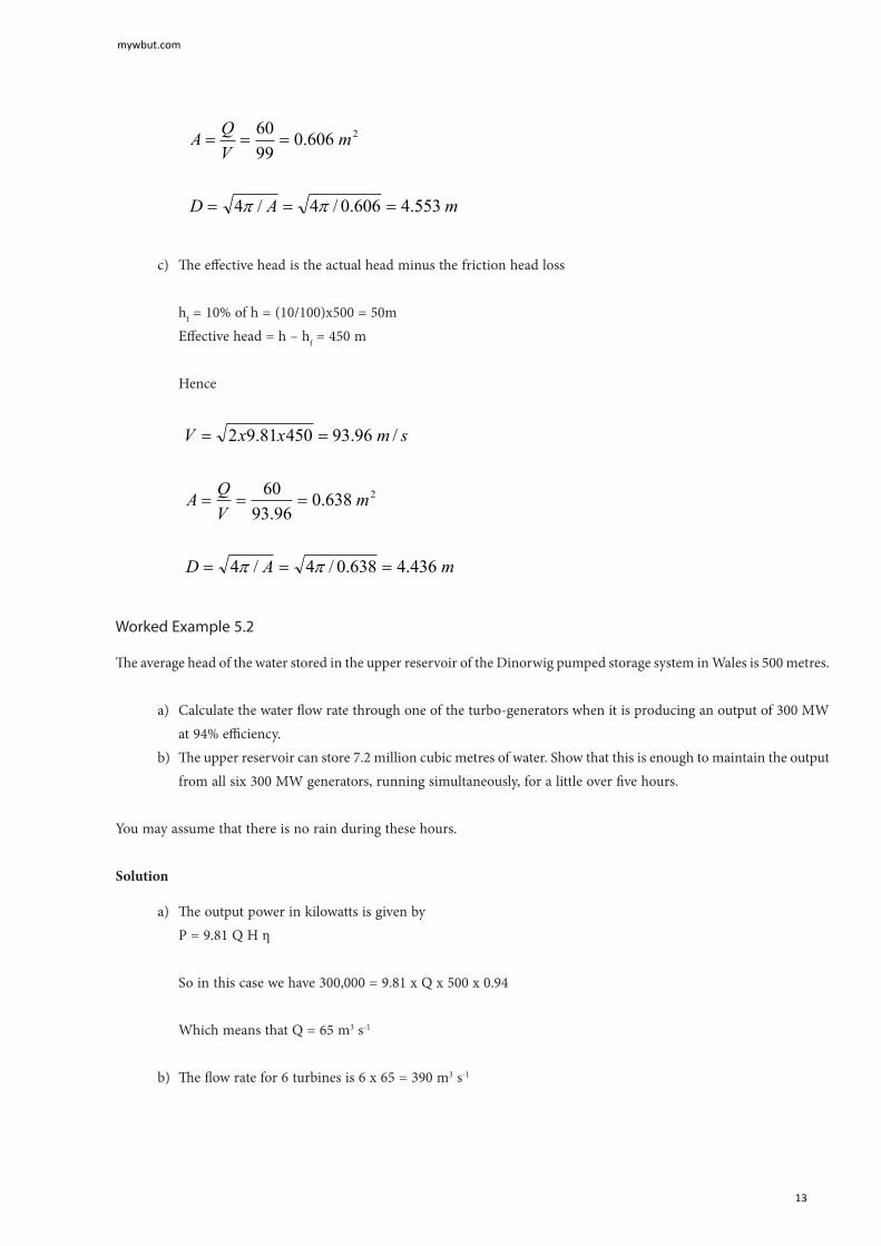
c) The effective head is the actual head minus the friction head loss
hf = 10% of h = (10/100)x500 = 50mEffective head = h – hf = 450 m
Hence
Worked Example 5.2
The average head of the water stored in the upper reservoir of the Dinorwig pumped storage system in Wales is 500 metres.
a) Calculate the water flow rate through one of the turbo-generators when it is producing an output of 300 MW at 94% efficiency.
b) The upper reservoir can store 7.2 million cubic metres of water. Show that this is enough to maintain the output from all six 300 MW generators, running simultaneously, for a little over five hours.
You may assume that there is no rain during these hours.
Solution
a) The output power in kilowatts is given byP = 9.81 Q H η
So in this case we have 300,000 = 9.81 x Q x 500 x 0.94
Which means that Q = 65 m3 s-1
b) The flow rate for 6 turbines is 6 x 65 = 390 m3 s-1
mywbut.com
13
And the available supply will maintain this for
7,200,000/390 = 18,442 seconds,
Which is 18442/3600 = 5.12 hours.
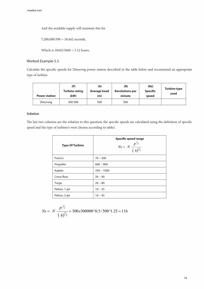
Worked Example 5.3
Calculate the specific speeds for Dinorwig power station described in the table below and recommend an appropriate type of turbine.
Power station
(P)
Turbine rating
(kW)
(h)
Average head
(m)
(N)
Revolutions per
minute
(Ns)
Specific
speed
Turbine type
used
Dinorwig 300 000 500 500
Solution
The last two columns are the solution to this question; the specific speeds are calculated using the definition of specific speed and the type of turbine/s were chosen according to table1.
Type Of Turbine
Specific speed range
Francis 70 – 500
Propeller 600 – 900
Kaplan 350 – 1000
Cross-flow 20 – 90
Turgo 20 – 80
Pelton, 1-jet 10 – 35
Pelton, 2-jet 10 – 45
mywbut.com
14

Checking the values in the table, this lies in the Francis turbine range
Power station
(P)
Turbine rating
(kW)
(h)
Average head
(m)
(N)
Revolutions per
minute
(Ns)
Specific
speed
Turbine type
used
Dinorwig 300 000 500 500 116 Francis
5.7 Tutorial Problems
5.1 A small-scale hydraulic power system has an elevation difference between the reservoir water surface and the pond water surface downstream of the turbine is 10 m. The flow rate through the turbine is 1 m3/s. The turbine/generator efficiency is 83%. Determine the power produced if:
a) Flow losses are neglected.b) Assume friction loss equivalent to 1 m head.
Ans:( 81 kW, 73 kW)
5.2 A hydro-electric power plant based on the Loch Sloy in Scotland has an effective head of 250 metres. If the flow rate of 16 m3/s can be maintained, determine the total power input to the turbine assuming a hydraulic efficiency of 98% ; and
a) the pressure difference across the turbine.Ans: (38 MW, 2.4 MPa)
5.3 A proposed hydropower plant to be built using a reservoir with a typical head of 18m and estimated power of 15 MW. You are given the task to select an appropriate type of turbine for this site if the generator requires the turbine to run at a fixed speed of 120 rpm.
Ans: (Ns=396, Francis or Kaplan)
mywbut.com
15


![Archimedes Powerpoint 8.12.2008.ppt [Kompatibilitätsmodus]haftendorn.uni-lueneburg.de/geschichte/griechen/Archimedes-berlips-nolte.pdf · Biographie IBiographie I • Archimedes](https://img.dokumen.tips/doc/110x75/5d66c48288c99356168b52cb/archimedes-powerpoint-8122008ppt-kompatibilitaetsmodus-biographie-ibiographie.jpg)