Embed Size (px)
Citation preview

..5:.. American ~ ~ Megatrends
AMIKey-3 38813 Keyboard Controller
User's Guide
MAN-AMIKey13 6119/97

© Copyright 1994- 1997 American Megatrends, Inc. Al! rights reserved. American Megatrends, Inc.
This publication contains proprietary information which is protected by copyright. No part of this publication may be reproduced, transcribed, stored in a retrieval system, translated into any language or computer language, or transmitted in any form whatsoever without the prior written consent of the publisher, American Megatrends, Inc.
Limited Warranty
Buyer agrees if this product proves to be defective, that American Megatrends, Inc. is only obligated to replace or refund the purchase price of this product at American Megatrend's discretion. American Megatrends shall not be liable in tort or contract for any loss or damage, direct, incidental or consequential. Please see the Warranty Registration Card shipped with this product for full warranty details.
Limitations of Liability
In no event shall American Megatrends be held liable for any loss, expenses, or damages of any kind whatsoever, whether direct, indirect, incidental, or consequential, arising from the design or use of this product or the support materials provided with the product.
Trademarks
American Megatrends acknowledges the following trademarks:
Mitsubishi is a registered trademark of Mitsubishi Corporation. MS-DOS and Microsoft are registered trademarks of Microsoft Corporation. Microsoft Windows, Windows NT, and Windows 95 are trademarks of Microsoft Corporation. Novell NetWare is a registered trademark of Novel! Corporation. Unix and SCO are registered trademarks of The Santa Cruz Operation, Inc. 3COM is a registered trademark of 3COM Corporation. IBM, AT, VGA, PS/2, MCA, OS/2, and EGA are registered trademarks oflnternational Business Machines Corporation. PC-DOS, XT and CGA are trademarks ofIntemational Business Machines Corporation. DEC is a registered trademark of Digital Equipment Corporation.
Revision History
6/25/96 12/20/96 117197 6/5/97 6/19/97
Initial release. Added chapter about smart battery support. Added additional commands. Added additional commands Added additional commands
ii AMIKey 38813 Keyboard Controller User's Guide

Table of Contents
1 AMIKey/38813 Keyboard Controller Features ......... 1
2 Keyboard Controller Memory Map ........................... 9 AMIKey-3 138813 Pinout forM38813 ................................................... 15 Key Scan Output Level Option .............................................................. 16 Auxiliary Device Control Options .......................................................... 16
3 Keyboard Controller Functions .............................. 17 Computer and Keyboard Controller Command Interface ....................... 20 Keyboard Controller Status Register ...................................................... 21 Keyboard Controller Command Byte ..................................................... 23
4 Keyboard Controller Commands ............................ 25 Standard Keyboard Controller Commands ............................................. 25 Special Keyboard Controller Commands ............................................... 26 Keyboard Commands ............................................................................. 30 Auxiliary Device Commands .................................................................. 31 Accessing M38813 RAM Locations ...................................................... 32
5 Scan Code Controller .............................................. 35 Default Matrixes ..................................................................................... 36 Scan Code Generation ............................................................................ 37 Special Handling Scan Codes and Fn_Shiftable Keys ........................... .41 Numeric Keypad .................................................................................... .44 Internal Numeric Keypad Control .......................................................... 46
6 Smart Battery Support ............................................ 49 Battery Interface Commands ................................................................. .49 DAh Send Data to an 5MBus Device ..................................................... 50 DBh Get Data from 5MBus Device ....................................................... 51 DDh Get Battery Status Word ................................................................ 51 Error Codes for Commands DAh, DBh, and DDh ................................. 52 Smart Battery Status Monitoring ............................................................ 52 Memory Map for Battery Management .................................................. 53
Index ............................................................................ 57
Preface iii

Preface
Purpose This manual provides sufficient technical information for the OEM to design system hardware based on the Mitsubishi® 38813 keyboard controller. This manual was written for the OEM to assist in the proper use and operation of the American Megatrends keyboard controller.
If You Need Help
Call American Megatrends technical support at 770-246-8645 if you have problems. The hours are 8:00 AM-7:00 PM EST.
Tech Support Information Gather the following information before calling technical support:
BBS
• the system configuration, including hard disk drive type, floppy drives, amount of memory, type of monitor and type of keyboard (and model number).
• the keyboard controller reference number, • the operating system/environment (DOS, Windows, OS/2,
Unix), • contents of AUTOEXEC.BAT and CONFIG.SYS, • all resident programs (loaded or not), • the system BIOS reference number, • the CPU type and clock frequency and the keyboard
controller clock frequency, and • a clear description of the problem.
You can access American Megatrends product information on the American Megatrends BBS.
Data Transmission The American Megatrends BBS automatically handles modems with data transmission rates from 1,200 to 28,800 bps.
Cont'd
iv AMIKey 38813 Keyboard Controller User's Guide

If You Need Help, Continued
Phone Numbers The BBS requires no parity, eight data bits, and one stop bit. The characteristics of the American Megatrends technical support, BSS, and other important phone numbers are:
Phone Number/Address Characteristics Tech SUPIJort Voice 770-246-8645 Tech Support Fax 770- 246-8772 Sales 800-828-9264 Internet Address [email protected] Web Site http://www.meKatrends.com 770-246-8780 28,800 baud rate. Supports v.34. 770-246-8781 28,800 baud rate. Supports v.34. 770-246-8782 Supports HST and v.42. 770-246-8783 Supports HST and v.42.
Preface v

vi AMIKey 38813 Keyboard Controller User's Guide

1 AMIKey/38813 Keyboard Controller Features
The AMIKey/38813 keyboard controller firmware features include:
• based on the Megakey keyboard controller code, • supports ISA, EISA, and MCA® architecture, • provides transparent software Gate A20 support, • supports an internal keyboard, • supports auxiliary devices, • supports an internal scan code controller, • supports internal pointing devices, • supports an internal numeric keypad, • supports direct LED control, and • supports the smart battery 5MBus interface.
External Keyboard and Auxiliary Devices The American Megatrends AMIKey/38813 keyboard controller firmware supports:
• standard IBM PCI A T® computers, • IBM PS/SS numeric keypads, and • PS12® auxiliary devices.
Cont'd
Chapter 1 Features 1

Features, Continued
Simultaneous Use of External and Internal Devices The firmware provides: simultaneous use of external and internal keyboards, and simultaneous use of external and internal auxiliary devices.
Hot Pluggability The firmware provides: hot pluggability of external keyboard and PS/2 devices and hot port swapping of external devices.
Power Management Support The firmware supports: WAIT Mode and STOP Mode.
Password and Hot Key Support The firmware supports: a BIOS password and general and function hot keys.
Downloadable Features The firmware supports: downloadable internal keyboard matrix, and downloadable function shifted key table.
Based on Megakey Code AMIKey has a modular set of features. This has come from the previous versions of American Megatrends keyboard controllers. This has been brought to give optimum performance and flexibility to include future enhancements in keyboard controller computer designs.
ISA, EISA, and MCA Support The AMIKey/ 38813 firmware supports a superset of IBM PS/2 keyboard and auxiliary device controller host interface. The system BIOS can configure the AMIKey as an AT 8042 with no PS/2 support. The default is PS/2 support. The IRQ12 line is not normally connected on the AT schematic but is connected on the MCA and EISA schematics. If the IRQ12 line is connected on the AT schematic, mouse support can be achieved through port swapping with only one external keyboard connector.
Cont'd
2 AMIKey 38813 Keyboard Controller User's Guide

Features, Continued
Transparent Software Gate A20 Support GateA20 commands access system memory above 1 MB. These commands are often used in Windows™ and Novell NetWare® networking applications. As machine speeds and software memory requirements have increased, the number of Gate A20 commands also increased. Most chipsets directly handle Gate A20 commands, speeding system performance.
Internal Keyboard Scan Code Controller This feature provides a fully functional and compatible internal parallel keyboard. The internal scan code controller responds to all keyboard commands and produces 101, 102, 105, and 106 key keyboard-compatible data.
Internal Auxiliary Device Support The AMIKey/ 38813 firmware supports an additional PS/2 port for an internal pointing device such as a Touch Pad, track ball, or glide point.
Internal Numeric Keypad Support The firmware supports a numeric keypad centered around the letter 'I'. The system BIOS can configure the keyboard controller to enable numeric keypad support. If the external numeric keypad or the keyboard is present, the computer can (optionally) choose the internal numeric pad that is supported.
Cont'd
Chapter 1 Features 3

Features, Continued
Direct LED Support The firmware uses the LED drive port to show the Scroll Lock, Caps Lock, and Num Lock status by driving the corresponding LEDs directly. When the corresponding bit is set, the LED glows unless it is Off. Up to four LEDs can be driven directly from the keyboard controller, freeing up an additional port pin. This pin can be used for the function bit status.
External Keyboards The firmware supports many types of external keyboards including all AT, PS/2, 84-key, lOI-key, 102-key, lOS-key, or I06-key keyboard.
External PS/2 Style Auxiliary Devices The firmware is made compatible to any PS/2 mouse or any auxiliary device that has a PS/2 serial interface.
External and Internal Keyboards Simultaneously The firmware allows you to use both the external and internal keyboards at the same time. So, the special features such as Fn hot keys that are available only in the internal keyboard can be used while using the external keyboard. This way it gives more user flexibility and convenience.
Simultaneous External and Internal Auxiliary Devices The firmware supports both external PS/2 mouse and internal auxiliary devices (any kind of pointing device with a PS/2 interface), making them usable at the same time. Users can choose from many types of pointing devices.
Cont'd
4 AMIKey 38813 Keyboard Controller User's Guide
Features, Continued
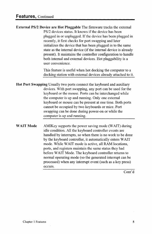
External PS/2 Device are Hot Pluggable The firmware tracks the external PS/2 devices status. It knows if the device has been plugged in or unplugged. If the device has been plugged in recently, it first checks for port swapping and later initializes the device that has been plugged in to the same state as the internal device (if the internal device is already present). It maintains the controller configuration to handle both internal and external devices. Hot pluggability is a user convenience.
This feature is useful when hot docking the computer to a docking station with external devices already attached to it.
Hot Port Swapping Usually two ports connect the keyboard and auxiliary devices. With port swapping, any port can be used for the keyboard or the mouse. Ports can be interchanged while the computer is up and running. Only one external keyboard or mouse can be present at one time. Both ports cannot be occupied by two keyboards or mice. Port swapping can be done during power-on or while the computer is up and running.
WAIT Mode AMIKey supports the power saving mode (W AIT) during idle condition. All the keyboard controller events are handled by interrupts, so when there is no work to be done by the keyboard controller, it automatically enters WAIT mode. While WAIT mode is active, all RAM locations, ports, and registers maintain the same status they had before WAIT Mode. The keyboard controller returns to normal operating mode (so the generated interrupt can be processed) when any interrupt event (such as a key press) occurs.
Cont'd
Chapter 1 Features 5

Features, Continued
STOP Mode This is a command initiated mode. Generally, when the computer is entering suspend mode, the command CBh makes the keyboard controller enter STOP mode. The keyboard controller leaves STOP mode when:
• a hardware reset occurs, • a host command or data is received, or • a key is pressed on the internal keyboard.
This keypress can also be used to wake the computer up by performing the assigned wake up task. The wake-up procedure is controlled by Anykey wakeup and Anykey resume flags.
If the Anykey wakeup and Anykey resume flags are set, the wakeup task is executed automatically when the keyboard controller leaves STOP mode. This task may cause an SMI or another event that, in tum, cause computer operation to resume. If the Anykey resume flag is zero, the computer can be resumed by an hot key event.
Password Support The keyboard controller provides the keyboard password feature. This password is available in addition to the password provided by the system BIOS. Depending on the implementation, the keyboard controller password can be the same as the system BIOS password.
Quick Lock Support The keyboard and mouse are locked until the user enters the correct password. The keyboard controller password is 6 bytes long with a null character at the end. The password must be loaded before this feature can be used. By default, either <Function key> <Backspace> or <Ctrl> <Alt> <Backspace> locks the keyboard and mouse under the Quick Lock enabled state. The keystroke combinations can be changed to any other keystroke combination, if desired.
The keyboard and mouse can be locked without leaving the user application. The faceplate LEDs are flashed when the keyboard controller enters the quick lock state. LED flashing is disabled automatically after a predefined time. LED flashing stops after the user enters the correct keystroke combination.
Cont'd
6 AMIKey 38813 Keyboard Controller User's Guide

Features, Continued
Hot Key Support AMIKey supports three types of hot keys:
• function hot keys • pulse hot keys, and • general hot keys.
Hot keys set, clear, toggle, or pulse the designated port pin. When the hot key is pressed, an external SMI or another interrupt occurs. A variable is set to indicate the hot key that was pressed. The system BIOS recognizes the interrupt and sends a CDh command to the keyboard controller to find the hot key that caused the SMI. The BIOS executes the task assigned to that hot key.
Function Hot Keys Function hot keys are invoked by pressing a <Function key> <Function key> keystroke combination. A function key is any key from FI to F12. When this key combination is pressed, the function task is set pending and is executed when the function key is released.
Pulse Hot Keys The pulse hot keys are invoked by pressing <Function key> <pulse hot keyX> keystroke combination on the internal keyboard. Any key on the internal keyboard can be configured as a pulse hot key. The keyboard controller sends low-going pulses at the typematic rate to the designated port pin when the specified keystroke combination is pressed. The pulses are used for controlling brightness, contrast and volume.
General Hot Keys General hot keys are invoked by pressing either <Ctrl> <Alt> <hot key> or <Function key> <hot key>. The hot key is any non-extended key. A non-extended key is a key that produces only one scan code per MakelBreak). The scan code value of the key used as a general hot key is stored in the RAM location by the system BIOS. The corresponding task is stored in the corresponding Key task RAM location. For <Ctrl> <Alt> <hot key> keystroke combinations, the corresponding task is set pending and is executed when all hot key keys are released. For all <Function key> <hot key> keystroke combinations, the task is executed when the Hot key is released.
Cont'd
Chapter 1 Features 7

Features, Continued
Smart Battery 5MBus Interface This feature provides an interface to smart batteries that are compatible with the IntellDuracell 5MBus interface specification. The system BIOS and any application can retrieve battery-related data using this interface.
Downloadable Internal Keyboard Matrix The firmware allows you to download the internal keyboard matrix through the BIOS at power on. Any value from OOh to FFh can be placed in the matrix, depending on the functionality requirement. A numeric keypad centered on the letter "I" is made available by pressing Fn key or with Num Lock on. Any 128 key matrix location can be modified at any time by writing to the corresponding RAM location using extended command BBh and an index value from 80h through FFh with bank 0 selected.
Downloadable Function Key Table The firmware can down load the function modifiable keys. Any value from OOh through BFh can be put in this table. The table stores the scan code value of a specific key when it is pressed alone (unshifted value) and if it is used in conjunction with the function key (fn_shifted value). These key values include standard keys, hot keys, and special handled keys for full functionality.
Speed Independent Operation The AMIKey keyboard controller works independently with either a 4 MHz or 8 MHz clock. AMIKey automatically adjusts all clock-related variables. The default clock speed is 4 MHz. The system BIOS can change the keyboard controller speed to 8 MHz by executing the DFh command.
8 AMIKey 38813 Keyboard Controller User's Guide

2 Keyboard Controller Memory Map
The AMIKey/388 I 3 keyboard controller allows the system BIOS or the OEM keyboard utility to read from or write to the 384 byte RAM using extended commands OB8h through OBBh. The 38813 memory map is shown below. The bit definitions describe all diagnostics and state saving/restoring information that is needed to understand the M38813 internal states.
Symbol RAM Description Location (Ran!!e)
SFR area OOOh- M38813 Special Function Registers 03Fh
BUFFER 40h General purpose temporary register Rl 41h General purpose register r 1
Stat8042 42h Controller status flags Bit Description 7 Parity error during receive. 6 General timeout error. Local bit definition/or bit 5-0 5 mouse IRQ pulse type. 4 Reserved. 3 A6 flag and password
active. 2 Reserved. 1 Break code flag. 0 PS/2 interface System bit definition for bit 5-0 5 1 Mouse data output buffer
full 4 1 Keyboard not inhibited. 3 1 Last data output in port 64. 2 1 System flag bit set. 1 1 Input buffer full. 0 1 Output buffer full.
R3-R7 43h-47h Temporary subroutine scratch registers (6 bytes)
STACK 48h-56h System Stack (16 bytes) STACK 57h Stack Pointer BLANK 58h Unused
SWAP XCHG 59h Scratch Register MS RESP COUNTER 5Ah Mouse response counter KB RESP COUNTER 5Bh Keyboard response counter
Chapter 2 Keyboard Controller Memory Map 9

Symbol RAM Description Location (Range)
PASSWORD PTR 5Ch Password Pointer PORT 60 CHAR 5Dh Old character buffer
WAKEUP TASK REG 5Eh Wakeup task storage register MEM INDEX 5Fh Internal memory index register
CCB 60h Keyboard Controller command byte. Bit Description 7 Reserved (must be 0). 6 I IBM Keyboard translate
mode. 5 I Disable mouse interface. 4 I Disable keyboard
interface. 3 I Keyboard inhibit override. 2 I Set system flag. 1 I Enable mouse interrupt. 0 I Enable keyboard interrupt.
USER RAM 6lh-7Fh IBM defined User RAM (20-3Fh) PASSWORD AREA 80h-86h Password storage area (6 bytesl
UNUSED 87h-8Bh Unused Memory Area Pk sel byte 8Ch Pulse key option byte
debounce time 8Dh MakelBreak deb ounce time pulse width 8Eh Pulse width for function hot keys
HK FLAG BYTE 8Fh Hot key Make/Break flags SCODE HKl 90h Hot keyl scan code storage SCODE HK2 9lh Hot key2 scan code storage SCODE HK3 92h Hot key3 scan code storage SCODE HK4 93h Hot key4 scan code storage SCODE HK5 94h Hot key5 scan code storage SCODE HK6 95h Hot key6 scan code storage TASK HKl 96h Hot key 1 task storage TASK HK2 97h Hot key2 task storage TASK HK3 98h Hot key3 task storage TASK HK4 99h Hot key4 task storage TASK HK5 9Ah Hot key5 task storage
BATTERY_CONFIG 9Bh- Storage for battery configuration AOh data.
Unused Alh- Unused Memory Area B2h
Kbc_State3 B3h Keyboard controller flag byte Bits 7-2 Reserved Bit 1 Enable IRQl2 tristate Bit 0 Ghost keycheck disable
Ccdata B4h Comparator control data
10 AMIKey 38813 Keyboard Controller User's Guide

Symbol RAM Description Location (Range)
Aux_Config B5h Bits 7-5 Reserved Bit 4 Aux. control bit 1 Bit 3 Aux. control bit 0 Bits 2-0 Reserved
Prescale B6h Timer pre scale value CF0813 B7h Keyboard controller configuration
register Bits 7-6 Reserved Bit 5 Int. aux. present Bits 4-3 Reserved Bit 2 Controller speed Bit 1 Reserved Bit 0 Scan method
MSTATE4 B8h Auxiliary status register Bit 7 Station req. hit Bit 6 Aux. tested Bits 5-4 Reserved Bit 3 Expect aux. data bit 0 Bit 2 Expect aux. data bit 1 Bit 1 Last aux. data bit 1 Bit 0 Last aux. data bit 0
KBMSidletimer B9h Idle timer PlDATA BAh Emulated Port 1 data
MSTATEI BBh Mouse status information Bit Description 7 ms_data_bit(Status/data) 6 ms_modebit (remote/stream) . 5 ms_flag bite enable/disable) 4 ms_scale bit(2: 1/1: I). 3 Wrap_mode bit. 2 Unused. 1 ms_f3 flag. 0 ms e8 flag.
Chapter 2 Keyboard Controller Memory Map 11

Symbol RAM Description Location (Range)
MSTATE2 BCh Mouse Status information Bit Description 7 Int. aux packet count (bit I) 6 Int. aux packet count (bit 0) S External mouse attached 4 Mouse resolution (bit 1)/ 3 Mouse resolution (bit 0). 2 Unused. 1 Unused. 0 Unused.
MSTATE3 BDh Keyboard/Mouse status information Bit Description 7 Delay _flag bit. 6 Set Anykey resume bit. S Set Anykey wakeup bit. 4 External keyboard connected. 3 Ext. aux packet count (bit 1). 2 Ext. aux packet count (bit 0). 1 Aux. last data pointer (bit 1). 0 Aux. last data pointer (bit 0).
FUNCTSK REG BEh FN hot key task storage r<:gister INT_FN_REQ_NUM BFh Data for get interrupt function
number TYPEMATICRATE COh Typematic rate.
Bit Description 7 Auto_repeat bit. 6 Typematic rate delay (bit 1). S Typematic rate delay (bit 0). 4 Typematic rate (bit 4). 3 Typematic rate (bit 3). 2 Typematic rate (bit 2). 1 Typematic rate (bit 1). 0 Typematic rate (bit 0).
LED_FLAG_BYTE Clh LED and Control flags. Bit Description 7 Alt key status bit. 6 Ctrl key status bit. S Left Shift status bit. 4 Right Shift status bit. 3 Function Key LED bit. 2 Caps Lock LED bit. I Num Lock LED bit. 0 Scroll Lock LED bit.
CH BUFF HEAD C2h Character buffer head pointer. CH BUFF TAIL C3h Character buffer tail pointer. SC BUFF PTR C4h Scanner buffer pointer
LAST SCAN INDEX CSh Last scanner character found
12 AMIKey 38813 Keyboard Controller User's Guide

Symbol RAM Description Location (Range)
DELAY _COUNT_BYTE C6h Delay Counter Bit Description 7 Unused. 6 Unused. 5 Unused. 4 Delay counter (bit 4). 3 Delay counter (bit 3). 2 Delay counter (bit 2). 1 Delay counter (bit 1). 0 Delay counter (bit 0).
KBMS_COMMAND_ST C7h Keyboard Command Status ATUS Bit Description
7 Keyboard and mouse port swapped.
6 Scanner disabled/enabled 5 Scan code Set (Bit 1). 4 Scan Code Set (Bit 0). 3 Tl_flag bit. 2 Keyboard command flag(bit 2). 1 Keyboard command flag(bit 1). 0 Keyboard command flag(bit 0).
CH_BUFFER CSh-D7h Character buffer Character buffer start address is CSh Character buffer end address is DOh
Unused DSh- Unused DAh
KBCFLAGS DBh Keyboard Command Status Bit Description 7 Memory Page Index (bit I). 6 Memory Page Index (bit 0). 5 Disable internal auxiliary
device. 4 Hot key make flag 3 Numeric pad lock bit 2 Function pad lock bit 1 Disable hot pluggability 0 Error flag
DCh Mouse Sampling Rate MSSMPL_RA TE OAh 10 Packets/sec
14h 20 Packets/sec 2Sh 40 Packets/sec 3Ch 60 Packets/sec 50h SO Packets/sec 64h 100 Packets/sec CSh 200 Packets/sec
Chapter 2 Keyboard Controller Memory Map 13

Symbol RAM Description Location (Range)
Kbs_statel DDh Keyboard controller flag register Bit 7 Counter Bit 4 Bit 6 Counter Bit 3 Bit 5 Counter Bit 2 Bit 4 Counter Bit 1 Bit 3 Counter Bit 0 Bit 2 LED flash bit Bit 1 LED tmpstp bit Bit 0 Reserved
Unused DEh- Unused memory DFh
SCBUFFER EOh- Scanner buffer E9h Scanner buffer start address=EOh
Scanner buffer end addres=D8h SCFLAG_BUFFER EAh- Scanner buffer flag byte storage
F3h The scanner buffer flag byte start address is EAh. The scanner buffer flag byte end address is F4h.
Unused F4h - Unused memory FFh
FN_SHFLT ABLE lOOh- RAM loaded function shift code 13FH table (64bytes)
SCAN_MATRIX l40h - User-defined scan code set_2 table lBFh (128 bytes).
BATLDATA lCOh- Smart battery handling data registers lFFh
Unused 200h-23Fh
14 AMIKey 38813 Keyboard Controller User's Guide

AM I Key-3 138813 Pinout for M38813
Data bus
The recommended pin configuration for implementing AMIKey-3/38813 using a Mitsubishi M38813 keyboard controller in a QFP- type package is:
,----'-1 DQ2 DQ3 1o.IG.-..... DQl DQ4 ~--4
'-_ ...... DQO DQ5 DATA BUS 10 Write -Wr DQ6 ~----1 10 Read -Rd DQ7 ~;""'-......I ROMKBCS -S P60lINT510BF2 ...... "---CMDIDATA FL AO P611CNTRO KBRST P5 3/-SRDY VCC 1-o'Jo--..;:) GA20 P5 2/SCLK P3 0 I-UI--..ICS HOTKEY5/GPI P5 l/TXD P3 1 ,"""",-~~ HOTKEY 4/GPI P5 OIRXD P3 2 ~"---K. EXKBDDATA P47IINT4 P3 3 """"'-~~ EXKBD CLK P4 61INT3 P3 4 ~"---....... IRQ 1 4 P4 5/IBF/OBFl P3 5 .... ---lU> IRQ 1 P4 4/0BFO ,."".. P3 6 f-oUo.I"---EXMS CLK P4 31INT2 ,. - ., P3 7 I-=U---K. EXMS DATA P4 2IINTI ........ PO 0 ~--GND CNVSS ~ PO 1 RESET RESET "'" PO 2 ~"---5MB CLK P4 llINTO ~ PO 3 1o=W---. 8MB DATA P4 0 CC) PO 4 10=--CLKi XIN ,."".. PO 5 ~--K. CLK 223 XOUT :&~ -. ., PO 6 ~---K G 4 VSS PO 7 t-:W---
SCROLL LOCK: 25 P2 7 PI 0 ~-~cs NUM LOCK 26 P2 6 PI 1 ~---ICCS CAPS LOC 27 P2 5 PI '2 """--K
24 P13~---ICCS LEDIJOP PI 4 HOTKEY3/GPIO P2 3 ~--K
PI S~--K HOTKEY2/GPI P2 2 Pl 6 ~--K HOTKEYlIGPIO 32 P2 1 PI 7 ..... __ HOTKEYO/GPIO,_L.A..II~ _______ ..J
Note Pins 8 and 9 can either be used as GA20/KBRST pins or as general purpose 110 or as general hot key task pins.
DQO - DQ7 are the data bus for host CPU interface.
Chapter 2 Keyboard Controller Memory Map 15

Key Scan Output Level Option
A keyboard matrix consists of 16 columns (scan lines) intersected by 8 rows (sense lines). To determine any key press on the rows involves scanning the scan lines one at a time and reading the sense lines. Different keyboard types require scan lines that are not being strobed to be either high impedance or to be driven high. The configuration bits involved in these options are:
Keyboard Type Ghost Key Function Scan Method Flag
Resistor network keyboard (default) I 0 Diode network keyboard I 1
Plain keyboard 0 1
Auxiliary Device Control Options
Bit
7-6 4 -3
2-0
The American Megatrends keyboard controller has several options that configure both internal and external auxiliary devices. These options are controlled by aux_config register variable. The default condition makes both internal and external auxiliary devices active simultaneously. This may cause some compatibility errors when both auxiliary devices are not PS/2-compatible. Only one device can be made active by downloading configuration bits. Auxiliary device control should only be configured by the system BIOS before the first PS/2 device command (the keyboard Reset command) is sent during POSTlResume. The Aux_config register contents at B5h are:
Description
Reserved Aux_cntrl_bitl and Aux3ntrl_bitO 00 Both devices are active simultaneously. 01 External Aux. Primary. The external auxiliary device is active ifit is
attached during POST/Resume. Both devices are active if the external auxiliary is hot plugged after POSTlResume.
10 Reserved 11 Either device support. Only the external auxiliary is active if it is present
during POST/Resume. Otherwise, only the internal auxiliary is active. Reserved
16 AMIKey 38813 Keyboard Controller User's Guide

3 Keyboard Controller Functions
The function of the keyboard controller in an ISA or EISA computer is shown below:
INT 09h
Keyboard
Sends a keyboard Make/Break scan code
Keyboard Controller
Sends a Make/Break system scan code
BIOS
Queries shift and toggle state flags Handles internal function requests. Converts system scan code to l6-bit character code. Sends character codc to INT 16h.
Receives and Translates Serial Data The keyboard controller receives serial data from the keyboard and/or mouse, checks the parity of the data and translates it to a system scan code, if necessary. The keyboard controller places the received and processed data in the data buffer and interrupt processor.
Executes System Commands The keyboard controller executes system commands through the controller command buffer (CCB) and places the result, if necessary, in the data buffer and then interrupts the CPU.
Cont'd
Chapter 3 Keyboard Controller Functions 17

Keyboard Controller Functions, Continued
Transmits Computer Data The keyboard controller transmits computer data, places it in the data buffer, and sends it to the
keyboard or mouse in a serial format with the parity bit inserted. It receives responses from the keyboard or mouse and reports to the computer Cpu.
Reports Errors The keyboard controller reports errors to the computer
through status registers at the time of data communication with the keyboard or mouse.
Receives Data from the Keyboard The keyboard sends data in an ii-bit
serial format to the keyboard controller:
Step By Action I keyboard The data begins with a start bit (low level) followed
by 8 data bits (least significant data bit first), an odd parity bit, and a stop bit (high level).
2 keyboard Data sent is synchronized with the keyboard clock. 3 keyboard On receiving a byte of data from the keyboard, the
controller keyboard controller places the data in its one-byte receive-data buffer and disables the keyboard interface until that data is picked up by the computer microprocessor. This avoids data overrun.
4 system Reads the data from the keyboard controller receive-CPU data buffer.
5 keyboard On parity error, the controller requests that the controller keyboard resend the data. If the error is repeated, the
controller sets the parity error bit in its status register. The keyboard controller sets the timeout bit in the status register if all eleven bits are not received within two milliseconds from the start of the transmission. If either error occurs, FFh is placed in the receive-data buffer.
Cont'd
18 AMIKey 38813 Keyboard Controller User's Guide

Keyboard Controller Functions, Continued
Possible Errors When Sending Data to the Keyboard Data is sent to the keyboard in the same serial format as data received from the keyboard. Some errors that may occur include:
If the time between request to send and start of transmission is greater than 15 milliseconds or the duration of transmission is greater than 2 milliseconds, the transmit timeout error bit is set in the status register.
The keyboard must acknowledge every transmission from the controller. If the acknowledgment has a parity error, the keyboard controller sets both the parity and transmit timeout error status bits.
If the acknowledgment does not arrive within 25 milliseconds, both the receive and transmit timeout error bits are set.
FEh is placed in the data buffer if any of these errors occur.
No retries are made for errors when transmitting to the keyboard.
Keyboard Inhibit The keyboard can sometimes be inhibited by shorting a jumper. See the motherboard manual for additional information. Although all transmissions from the computer to the keyboard are permitted when the keyboard is inhibited, the keyboard controller tests all data received from the keyboard. If it is a response to a command sent to the keyboard, it is placed in the data buffer.
It is ignored otherwise.
Chapter 3 Keyboard Controller Functions 19
Computer and Keyboard Controller Command Interface
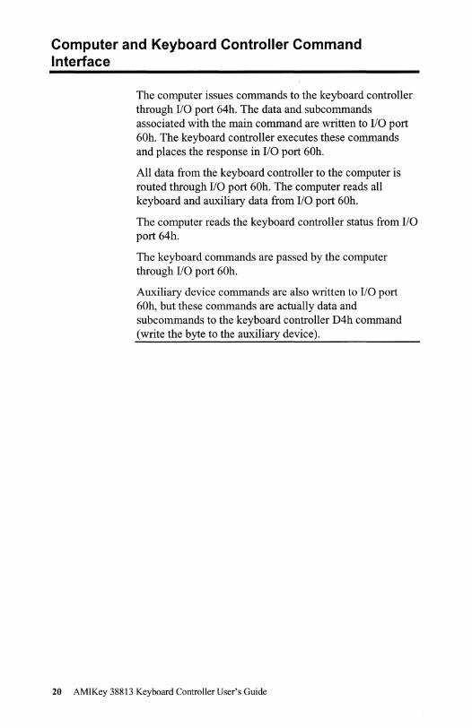
The computer issues commands to the keyboard controller through I/O port 64h. The data and subcommands associated with the main command are written to I/O port 60h. The keyboard controller executes these commands and places the response in I/O port 60h.
All data from the keyboard controller to the computer is routed through I/O port 60h. The computer reads all keyboard and auxiliary data from I/O port 60h.
The computer reads the keyboard controller status from I/O port 64h.
The keyboard commands are passed by the computer through I/O port 60h.
Auxiliary device commands are also written to I/O port 60h, but these commands are actually data and sub commands to the keyboard controller D4h command (write the byte to the auxiliary device).
20 AMIKey 38813 Keyboard Controller User's Guide

Keyboard Controller Status Register
The keyboard controller status register format is:
Bit Description
7 Parity Error 0 No parity error. I The last byte received from the keyboard had a parity error. The keyboard sends data with odd parity.
6 Timeout Error 0 No timeout error. I A data transmission from the keyboard to the keyboard controller was not properly completed within the pre-defined time limit.
5 Auxiliary Output Buffer Full 0 Keyboard data I Mouse data
4 Inhibit Switch This bit reflects the state of the keyboard inhibit switch. This bit is updated when the controller writes to the output buffer. 0 Keyboard inhibited I Keyboard not inhibited
3 Command/Data Used by the keyboard controller to determine if the input buffer contains a command or data. 0 The system writes to the input buffer through I/O port 60h. I The system writes to the input buffer through I/O port 64h.
2 System Flag The keyboard controller can set this bit to 0 or I depending on the command from the computer. It is set to 0 after power on reset.
I Input Buffer Full 0 The keyboard controller input buffer is empty. I The system has written to the input buffer. This bit is reset to o when the controller reads the input buffer.
0 Output Buffer Full 0 The keyboard controller output buffer has no data. I The keyboard controller has written to the output buffer. The
keyboard controller set this bit to 0 when the computer reads the output buffer (60h).
Cont'd
Chapter 3 Keyboard Controller Functions 21

Keyboard Controller Status Register, Continued
The keyboard controller status register, which is read from I/O port 64h, indicates if the keyboard controller is ready to accept another command or if response data is ready from the previous command.
The computer can only send data or commands to the M38813 keyboard controller if the IBF (Input Buffer Full) flag is cleared. The data from the M38813 is valid only if the OBF (Output Buffer Full) flag is Set.
If the computer sends a command to the keyboard controller that has a response, the computer waits for the OBF flag to be set before reading the data from 1/0 port 60h.
22 AMIKey 38813 Keyboard Controller User's Guide

Keyboard Controller Command Byte
Bit 7
6
5
4
3
2
I
0
The internal status is defined by the keyboard controller command byte (CCB). The CCB resides in RAM location 20h, defined in the IBM 8042 programming specification. This location is mapped to 60h in the M38813 keyboard controller.
The CCB can be read from or written to using special commands or using the IBM standard commands. In the IBM standard command set, use command 20h to read the CCB and command 60h to write CCB command 60h.
Description Reserved
IBM PC Compatibility Mode 0 Pass untranslated scan codes to the computer. 1 Tr.anslate scan codes to IBM PC standard before sending to
the computer (default setting). Disable Auxiliary Device 0 Auxiliary device enabled. 1 Auxiliary device disabled (in an AT, use 1 for XT keyboards ).( default) Disable keyboard 0 Keyboard enabled. 1 Keyboard disabled (interface inactive). (Default) Inhibit override (in AT). Reserved in PS/2. 1 = disable keyboard inhibit function System Flag 0= System executing POST as a result of cold boot (Default). 1 = ~tem executing POST as a result of warm boot Enable Auxiliary OBF interrupt 0 (Default) 1 System interrupt generated when a byte is placed in the
auxiliary output buffer Enable Keyboard OBF Interrupt 1 System interrupt generated when a byte is placed in the output
buffer
Chapter 3 Keyboard Controller Functions 23

24 AMIKey 38813 Keyboard Controller User's Guide

4 Keyboard Controller Commands Standard Keyboard Controller Commands
The standard keyboard controller commands implemented
by 38813 keyboard controller for AT and PS/2
environments are:
Command AT PS/2 Description
OOh-lFh X X Read the contents of the designated RAM locations (20h - 3Fh) and send it to the computer
20h-3Fh X X Read the contents of the designated RAM locations 120h-3Fh) and send it to the computer
40h-SFh X X Get a byte of data from the computer and write into one of the RAM locations (20h - 3Fh)
60h-7Fh X X Get a byte of data from the computer and write into one of the RAM locations (20h-3Fh)
A4h X X Test password installed Returns OF Ah if password is loaded Returns OFlh if password is not installed
ASh X X Load password Loads password until a '0' is received from the computer
A6h X X Enable password Enables the checking of keystrokes for a match with the password
A7h X Disable auxiliary device
ASh X Enable auxiliary device
A9h X Test auxiliary device clock and data (interface tes1:)
AAh X X M38813 keyboard controller self test Returns 055h if successful.
ABh X X Test keyboard clock and data lines (interface test)
ADh X X Disable keyboard AEh X X Enable keyboard
COh X X Read input port (emulate port I )
C2h X X Poll input port high and put it in the status register
C3h X X Poll input port low and put it in the status register
DOh X X Read Port 2 (send the Gate A20 status to the computer).
Chapter 4 Keyboard Controller Commands 25

Command AT PS/2 Description
Dlh X X Write Port 2 (Set or reset the Gate A20 line based on system bit I).
D2h X X Send data back to the system as if it came from the keyboard.
D3h X Send data back to the system as if it came from the auxiliary device.
D4h X Output next received byte of data from system to auxiliary device
EOh X X Read test inputs. FEh X X Pulse the RC (the reset line) low for 6 J.lS.
Special Keyboard Controller Commands
Command AT AOh x
Alh x B8h x B9h x BAh x
BBh x
The special commands supported by the AMIKey keyboard controller are used to: • access internal RAM for loading an internal keyboard
matrix, • edit function key table, • set hot key values, and • set other configuration data.
PS/2 Description x Send American Megatrends copyright message to the
computer. x Send controller BIOS version number to the computer. x Configure the memory access index MEM INDEX* x Get current contents ofMEM INDEX x Read the contents of the memory location pointed by
MEM INDEX x Write the memory location pointed by MEM INDEX
26 AMIKey 38813 Keyboard Controller User's Guide

Command AT PS/2 Description
BCh x x Read or write the following controller variables pointed BDh by MEM_INDEX:
STAT8042 0 Controller status register Password_ptr I Pointer to password storage
area Wakeup_Tsk_Reg 2 Wakeup task storage register CCB 3 Controller Command Byte Debounce_time 4 Make/Break debounce
time Pulse_Width 5 Pulse width selection for
hot keys PLsel_byte 6 Pulse hot key control byte Func_Tsk_Reg 7 Function hot key task storage
register TypematicRate 8 Keyboard typematic rate
storage Led]laR-Byte 9 LED/Ctrl/ Alt/Shift status
register Kbms_Command_St A Command status register Delay_CounCByte B Typematic delay counter
value KBC]lags C Keyboard status flags register SCODE_HKI 0 Hot key I scan code storage SCODE_HK2 E Hot key 2 scan code storage SCODE_HK3 F Hot key 3 scan code storage SCODE_HK4 10 Hot key 4 scan code storage SCODE_HK5 11 Hot key 5 scan code storage SCODE_HK6 12 Hot key 6 scan code storage TASK_HKI 13 Hot key I task storage TASK_HK2 14 Hot key 2 task storage TASK_HK3 15 Hot key 3 task storage TASK_HK4 16 Hot key 4 task storage TASK_HK5 17 Hot key 5 task storage BatCPolLdelay_Timel8 Battery Polling delay time
value Batt_Alarm_Reg I 19 Battery alarm mask register BatCAlarm_Reg2 IA Battery alarm removed mask
register BatCAlarm_TsLReg 1B Alarm task storage register Kbc_Statel IC Keyboard controller flag
register I Aux_Config 10 Auxiliary configuration
register Kbcstate3 IE Keyboard controller flag
register 3
Clh x x Write emulated port I
Chapter 4 Keyboard Controller Commands 27

Command AT PS/2 Description CSh x x Read, Set, Clear, or Toggle port bits
Bit 7 0 Level I Pulse
Bits 6-5 00 Read 01 Set 10 Clear 11 Toggle
Bits 4-0 00h-07h Ports 0.0 - 0.7 08h-OFh Ports 1.0 - 1.8 10h-17h Ports 2.0 - 2.7 18h-19h Port 4.0, 4.1 lAh-lDh Ports 5.0 - 5.3 lEh-1Fh Ports 6.0,6.1
C8h x x Tristate IRQl2 Line OOh Tristate IRQl2 Olh Default IRQ12
CBh x x Enable password and flash LEDs CCh x x Enter Power Down State (STOP mode) CDh x x Get interrupt function request
OOh No keyboard controller function Olh HKI 02h HK2 03h HK3 04h HK4 OSh HKS 06h HK6 Quick Lock 07h Unused 08h Wakeup Event Request 09h Unused OAh FKI OBh FK2 OCh FK3 ODhFK4 OEh FKS FKI through FKl2 OFh FK6 Internal keyboard only IOh FK7 llh FK8 12h FK9 13h FKIO 14h FKll ISh FKl2 16h Pulse P2.0 17h Pulse P2.l 18h Pulse P2.2 19h Pulse P2.3 IAh Pulse PS.O IBh Pulse PS.l ICh Pulse PS.2 lDh Pulse PS.3 I Eh Battery alarm event
28 AMIKey 38813 Keyboard Controller User's Guide

Command AT PS/2 Description CFh x x Control Any Key Resume
00 Disable Anykey wakeup. 01 Enable Anykey wakeup and hot key resume. 10 Enable Anykey wakeup and Anykey resume. 11 Unused
D8h x x Auto sense external keyboard and mouse DAh x x Send data to an 5MBus device DBh x x Get data from an 5MBus device DDh x x Get the battery status word DFh x x 04h Set clock speed to 4 MHz
08h Set clock speed to 8 MHz
Chapter 4 Keyboard Controller Commands 29
Keyboard Commands
Note:
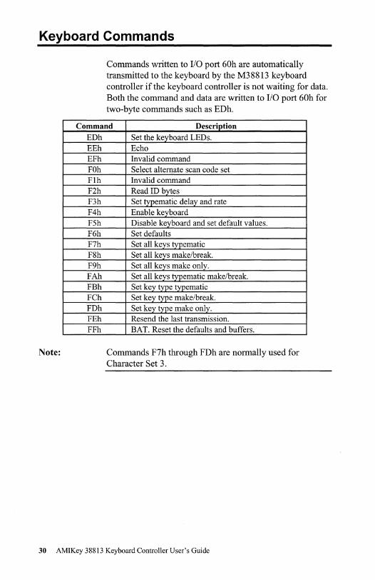
Commands written to 110 port 60h are automatically transmitted to the keyboard by the M38813 keyboard controller if the keyboard controller is not waiting for data. Both the command and data are written to 110 port 60h for two-byte commands such as EDh.
Command Description
EDh EEh EFh FOh Flh F2h F3h F4h F5h F6h F7h F8h F9h FAh FBh FCh FDh FEh FFh
Set the keyboard LEDs. Echo Invalid command Select alternate scan code set Invalid command Read ID bytes Set typematic delay and rate Enable keyboard Disable keyboard and set default values. Set defaults Set all keys typematic Set all keys makelbreak. Set all keys make only. Set all keys typematic makelbreak. Set key type typematic Set key type make/break. Set key type make only. Resend the last transmission. BAT. Reset the defaults and buffers.
Commands F7h through FDh are normally used for Character Set 3.
30 AMIKey 38813 Keyboard Controller User's Guide

Auxiliary Device Commands
Auxiliary Device Command Sequence The auxiliary device command sequence is:
Step Action I Write an M38813 OD4h command (Write Auxiliary Device) to
I/O port 64h. 2 Write command/data to I/O port 60h.
The above sequence is executed twice for 2-byte auxiliary device commands, such as the E8h Set Resolution command.
Auxiliary Device Commands
Command Description E6h Reset scaling E7h Set scaling E8h Set resolution E9h Status request EAh Set stream mode EBh Read data ECh Reset wrap mode EDh Invalid command EEh Set wrap mode EFh Invalid command FOh Set remote mode Flh Invalid command F2h Read device type F3h Set sampling rate F4h Enable auxiliary device F5h Disable auxiliary device F6h Set default values F7h Invalid command F8h Invalid command F9h Invalid command FAh Invalid command FBh Invalid command FCh Invalid command FDh Invalid command FEh Resend FFh Reset
Chapter 4 Keyboard Controller Commands 31

Accessing M38813 RAM Locations
Access
Location
The keyboard controller special commands B8h through BDh allow you to read and write to any RAM location from 40h to 23Fh (a total of 512 bytes). Commands BCh and BDh read and write the most commonly used status and configuration bytes, as required. These commands provide additional ways to access highly accessed RAM locations.
The 512 byte RAM area is divided into four 128 byte pages. Each page can be accessed by two variables:
• MEM_INDEX, and • KBC_FLAGS (Bits 7 and 6).
The location of the pages are
MEM INDEX value Page Accesses RAM 00 to 7Fh 1 40h to BFh 80h to FFh 2,3,or4 Depends on the setting of
KBC FLAGS Bits 7-6.
KBC_FLAGS KBC_FLAGS RAM locations Bit 7 Bit 6 accessed
0 0 140h to 1BFh 0 1 OCOh to 13Fh 1 0 OCOh to 13Fh 1 1 1COh to 23Fh
Downloadable Features RAM is made accessible to support downloadable features like the keyboard matrix and the function key table.
The most important downloadable feature is the keyboard matrix. The KBC_FLAGS bits 7-6 setting default is 00, so that it accesses the page corresponding to the matrix.
Cont'd
32 AMIKey 38813 Keyboard Controller User's Guide

Accessing RAM Locations, Continued
Changing the Function Key Table To change the function key table, set bits 7-6 ofKBC]LAGS to 10 or 01 (preferably 10). Memory index values from COh - FFh refer to 100h-13Fh for the function shift key table.
Smart Battery Memory locations above 1 COh are used for smart battery interface handling. This memory can be accessed by setting bits 7 and 6 ofKBC_Flags to 11 and setting Mem_index to 80h ... FFh.
You should set the page index bits to the default (00) once either the function key table has been modified or the smart battery related data has been accessed.
Chapter 4 Keyboard Controller Commands 33

34 AMIKey 38813 Keyboard Controller User's Guide

5 Scan Code Controller The keyboard controller monitors the status of all internal keyboard key switches. Based on the key pressed, it generates the scan codes according to the standard IBM scan code set specifications.
Internal and External Keyboard Support The M388l3 keyboard controller supports external and internal keyboards simultaneously. When no external keyboard is installed, the keyboard controller processes and replies to all keyboard commands.
38813 RAM
When both the internal and external keyboards are present, only internal keyboard responses are sent to the computer to avoid duplicate replies. The M388l3 scan code controller is fully compatible to the IBM 1011102 key keyboard specification with the exception is that it does not support scan code set 3 and related functions.
The keyboard controller RAM locations from 140h to IBFh(l28 bytes) store the internal keyboard matrix. The function key table is in RAM locations 100h to 13Fh.
The keyboard matrix values correspond to the default scan code set 2 values. This matrix can have values from OOh to FFh, depending on the keys required, such as:
• function modifiable, • extended keys (IBM-specific keys 75 to 89).
Keyboard controller special commands B8h through BBh load and edit these matrix values.
Chapter 5 Scan Code Controller 35

Default Matrices
Keyboard Matrix RAM locations Mem index OOh,OOh,76h,OOh,Och,34h,03h,33h I40h-147h SOh-S7h Obh,OOh,52h,OOh,OOh,OOh, 75h, Ilh I4Sh-14fh SSh-SFh OOh, I2h,Odh, 5Sh, 04h, 2ch,66h, 35h I50h-157h 90h-97h 5bh,S3h,54h,OOh,OOh,OOh,S9h,7ch I5Sh-15Fh 9Sh-9Fh I4h,OOh,Oeh,05h,06h,2eh,Olh,36h I60h-167h AOh-A7h 55h, Oah, 4eh, 7Ih 70h, 7dh, 6ch, OOh I6Sh-16Fh ASh-AFh OOh,OOh, I6h, Ieh,26h,25h,09h,3dh I70h-l77h BOh-B7h 3eh,46h,45h, 7Sh,07h, 7ah,69h,OOh I7Sh-17Fh BSh-BFh OOh,OOh, I5h, Idh, 24h,2dh, OOh, 3ch IS0h-IS7h COh-C7h 43h,44h,4dh,OOh,OOh,OOh,OOh,OOh ISSh-ISFh CSh-CFh 96h,OOh, Ich, IBh,23h,2Bh,5dh,3bh I90h-197h DOh-D7h 42h,4Bh,4Ch,OOh,OOh,OOh,OOh,OOh I9Sh-19Fh DSh-DFh OOh,59h,lah,22h,2Ih,2ah,5ah,3ah IAOh-IA7h EOh-E7h 4Ih,49h,OOh,77h,OOh,OOh,OOh,OOh IASh-IAFh ESh-EFh OOh,OOh,OOh,OOh,OOh,32h,29h,3Ih IBOh-IB7h FOh-F7h OOh,OOh,4ah, 72h, 74h,OOh,6bh, S7h IBSh-IBFh FSh-FFh
Default Function-Shifted Key Matrix
Fn-Shifted Keyboard Matrix RAM Mem -locations index
Un Fn Un Fn Fn Un Fn Un Values OSh 7Sh 06h 07h 91h SBh 90h SCh CO-C3h 100h-I07h CO-C7h 92h SFh 93h SEh Slh 86h S2h S7h C4-C7h 10Sh-IOFh CS-CFh SAh 9Ah SDh 7Eh SSh S4h 7Eh OSh CS-CBh 110h-117h DO-D7h 77h 07h 77h 9Sh S9h B2h OOh OOh CC-CFh l1Sh-11Fh DS-DFh 78h S4h 07h 8Sh SAh 7Eh OSh A6h DO-D3h 120h-127h EO-E7h 06h A7h 04h ASh OCh A9h 03h AAh D4-D7h 12Sh-12Fh ES-EFh OBh ABh S3h ACh OAh ADh Olh AEh DS-DBh 130h-137h FO-F7h 09h AFh 7Sh BOh 07h Blh IAh 61h DC-DFh 13Sh-13Fh FS-FFh
36 AMIKey 38813 Keyboard Controller User's Guide
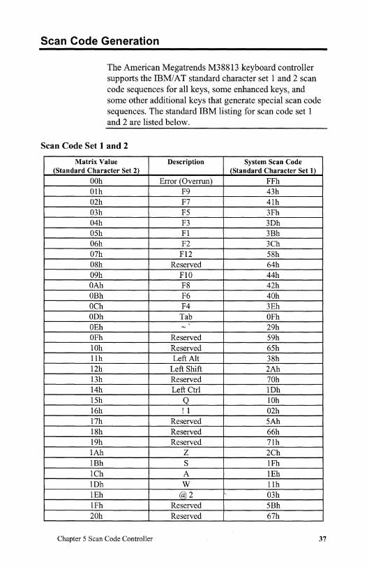
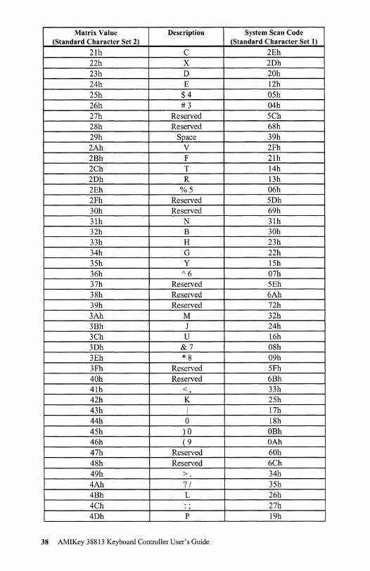
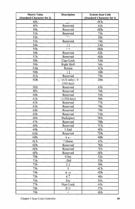
Scan Code Generation
The American Megatrends M388l3 keyboard controller supports the IBM! AT standard character set land 2 scan code sequences for all keys, some enhanced keys, and some other additional keys that generate special scan code sequences. The standard IBM listing for scan code set 1 and 2 are listed below.
Scan Code Set 1 and 2
Matrix Value Description System Scan Code (Standard Character Set 2) (Standard Character Set 1)
OOh Error (Overrun) FFh Olh F9 43h 02h F7 4lh 03h F5 3Fh 04h F3 3Dh 05h FI 3Bh 06h F2 3Ch 07h Fl2 58h 08h Reserved 64h 09h FlO 44h OAh F8 42h OBh F6 40h OCh F4 3Eh ODh Tab OFh OEh - 29h OFh Reserved 59h lOh Reserved 65h llh Left Alt 38h 12h Left Shift 2Ah l3h Reserved 70h 14h Left Ctrl lDh 15h Q lOh 16h ! 1 02h l7h Reserved 5Ah l8h Reserved 66h 19h Reserved 7lh lAh Z 2Ch lBh S lFh lCh A lEh lDh W llh lEh @2 03h lFh Reserved 5Bh 20h Reserved 67h
Chapter 5 Scan Code Controller 37
Matrix Value Description System Scan Code (Standard Character Set 2) (Standard Character Set 1)
21h C 2Eh 22h X 2Dh 23h D 20h 24h E 12h 25h $4 05h 26h #3 04h 27h Reserved 5Ch 28h Reserved 68h 29h Space 39h 2Ah V 2Fh 2Bh F 21h 2Ch T 14h 2Dh R 13h 2Eh %5 06h 2Fh Reserved 5Dh 30h Reserved 69h 31h N 31h 32h B 30h 33h H 23h 34h G 22h 35h Y 15h 36h 1\6 07h 37h Reserved 5Eh 38h Reserved 6Ah 39h Reserved 72h 3Ah M 32h 3Bh J 24h 3Ch U 16h 3Dh &7 08h 3Eh *8 09h 3Fh Reserved 5Fh 40h Reserved 6Bh 41h < , 33h 42h K 25h 43h I 17h 44h 0 18h 45h )0 OBh 46h (9 OAh 47h Reserved 60h 48h Reserved 6Ch 49h > 34h 4Ah ? / 35h 4Bh L 26h 4Ch .. 27h . , 4Dh P 19h
38 AMIKey 38813 Keyboard Controller User's Guide
Matrix Value Description System Scan Code (Standard Character Set 2) (Standard Character Set 1)
4Eh - OCh 4Fh Reserved 6lh 50h Reserved 6Dh 5lh Reserved 73h 52h " , 2Sh 53h Reserved 74h 54h { [ lAh 55h += ODh 56h Reserved 62h 57h Reserved 6Eh 5Sh Caps Lock 3Ah 59h Right Shift 36h 5Ah Return lCh 5Bh } ] lBh 5Ch Reserved 75h 5Dh I , \ (US only) - # 2Bh
(l02-key) 5Eh Reserved 63h 5Fh Reserved 76h 60h Reserved 55h 6lh \ I (102-key) 56h 62h Reserved 77h 63h Reserved 78h 64h Reserved 79h 65h Reserved 7Ah 66h Backspace OEh 67h Reserved 7Bh 6Sh Reserved 7Ch 69h 1 End 4Fh 6Ah Reserved 7Dh 6Bh 4~ 4Bh 6Ch 7 Home 47h 6Dh Reserved 7Eh 6Eh Reserved 7Fh 6Fh Reserved 6Fh 70h o Ins 52h 7lh , Del 53h 72h 2,), 50h 73h 5 4Ch 74h 6~ 4Dh 75h st 4Sh 76h Esc Olh 77h NumLock 45h 7Sh Fll 57h 79h + 4Eh
Chapter 5 Scan Code Controller 39

Matrix Value Description System Scan Code (Standard Character Set 2) (Standard Character Set 1)
7Ah 3 PgDn 51h 7Bh - 4Ah 7Ch * 37h 7Dh 9 PgUp 49h 7Eh Scroll Lock 46h 7Fh Sys Req (84-key) 54h
40 AMIKey 38813 Keyboard Controller User's Guide

'",
Special Handling Scan Codes and Fn_Shiftable Keys
The scan codes corresponding to the special handling routines for matrix values from 80h - BFh are listed below. The table on the previous pages (beginning on page 37) lists the scan codes that correspond to matrix values OOh -
7Fh.
Set or reset the internal flag within in handling routine and
finally the keyboard controller will send the special scan code according to the current shift status (Num Lock, Fn
shift, Shift, control and Alt).
Special Handled Key Codes
Matrix Description Explanation Matrix Description Explanation Value Value 080h Unused OAOh Unused 08lh Unused OAlh Unused 082h Unused OA2h Unused 083h F7 Scan code> OA3h L_Winkey Win95 key
80h 084h SysReq Scan code> OA4h R_Winkey Win95 key
80h 085h Unused OA5h Unused 086h Right Ctrl Flags and OA6h Func OAh do func task
EOseq 087h Right Alt Flags and OA7h Func OBh do func task
EOseq 088h PrtScm EO code seq OA8h Func OCh do func task 089h Pause EI code seq OA9h Func ODh do func task 08Ah Insert EO code seq OAAh Func OEh do func task 08Bh Home EO code seq OABh Func OFh do func task 08Ch PageUp EO code seq OACh Func IOh do func task 08Dh Delete EO code seq OADh Func lIh do func task 08Eh End EO code seq OAEh Func 12h do func task 08Fh Page Down EO code seq OAFh Func 13h do func task 090h UpArrow EO code seq OBOh Func l4h do func task 09lh Left Arrow EO code seq OBlh Func 15h do func task 092h Down EO code seq OB2h Break EO code seq
Arrow 093h Right EO code seq OB3h ~/@ Emulated key
Arrow 094h / EO code seq OB4h = / - Emulated key 095h keypad EO code seq OB5h + / : Emulated key
Enter
Chapter 5 Scan Code Controller 41

. .C
Matrix Description Explanation Matrix Description Explanation Value Value 096h Fn Flags OB6h R_Win_ Win95 key
MenuKey 097h Unused OB7h Func. 16h Pulse Low P2.0
098h Fn Lock Flags OB8h Func.17h Pulse Low P2.1
099h Unused OB9h Func. 18h Pulse Low P2.2
09Ah Num Lock Numlock OBAh Func. 19h Pulse Low P2.3 acts as pad
lock 09Bh Unused OBBh Func. IAh Pulse Low PS.O
09Ch Unused OBCh Func. IBh Pulse Low PS.I
09Dh Unused OBDh Func. ICh Pulse Low P 5.2
09Eh Unused OBEh Func.IDh Pulse Low P5.3
09Fh Unused OBFh Unused Unused
Fn Shifted Scan Codes If the matrix value is from COh to DFh, the current status of the function shift flag is checked and the scan code is chosen between the unshifted and Fn-shifted values as shown below. The selected scan code value goes through the same steps as the standard scan code values (0-BFh) and arrives at the final scan code sequence according to the specification. The scan code values from CO through DFh, which are not used by default, can be used for any key combination.
Fn_Shifted Scan Codes
Scan Code Value Matrix Description Value
Unshifted Fn shifted Un shifted Fn-shifted 005h 078h OCOh FI Fll 006h 007h OClh F2 Fl2 09lh 08Bh OC2h Left Arrow Home 090h 08Ch OC3h UpArrow PgUp 092h 08Fh OC4h Down Arrow PgDn 093h 08Eh OC5h Right Arrow End Ol4h 086h OC6h Left Ctrl Right Ctrl Ollh 087h OC7h Left Alt Right Alt 08Ah 09Ah OC8h Insert Num lock 08Dh 07Eh OC9h Delete Scroll lock 088h 084h OCAh PrtScm SysReq 07Eh 078h OCBh Scroll lock Fll 077h 007h OCCh Numlock Fl2 077h 098h OCDh Numlock Fn lock No 089h OB2h OCEh Pause Break
42 AMIKey 38813 Keyboard Controller User's Guide
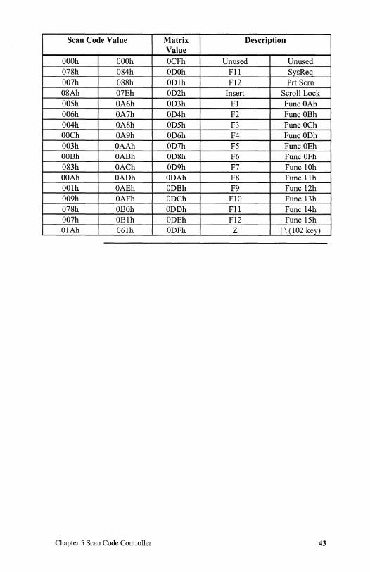
Scan Code Value Matrix Description Value
OOOh OOOh OCFh Unused Unused 078h 084h ODOh Fll SysReq 007h 088h ODlh F12 Prt Scm 08Ah 07Eh OD2h Insert Scroll Lock OOSh OA6h OD3h Fl Func OAh 006h OA7h OD4h F2 Func OBh 004h OA8h ODSh F3 Func OCh OOCh OA9h OD6h F4 Func ODh 003h OAAh OD7h FS Func OEh OOBh OABh OD8h F6 Func OFh 083h OACh OD9h F7 Func 10h OOAh OADh ODAh F8 Func llh OOlh OAEh ODBh F9 Func l2h 009h OAFh ODCh FlO Func 13h 078h OBOh ODDh Fll Func l4h 007h OBlh ODEh F12 Func ISh OlAh 061h ODFh Z 1\ (102 key)
Chapter 5 Scan Code Controller 43

Numeric Keypad
If the matrix value is from EOh to FFh, by default it is used for a numeric keypad defined by the keys around the letter 'I'.
If the matrix value is above EOh and below FFh, it is checked against Num Lock bit set or the Fn flag set and the scan code value is chosen between the unshifted and Fnshifted values as shown in the table below. The selected value will pass through the same steps as the standard scan code values (OOh through BFh) and arrive at the final scan code sequence. The key combination used for the matrix values from EOh to FFh is preprogrammed and cannot be modified by the user.
The various configurations that are valid for numeric keypad control are explained in "External Numeric Keypad Control".
Scan Code Value Matrix Description Value
Unshifted Fn shifted Un shifted Fn-shifted 03Bh 069h OEOh J 1 042h 072h OElh K 2 04Bh 07Ah OE2h L 3 03Ch 06Bh OE3h U 4 043h 073h OE4h I 5 044h 074h OESh 0 6 03Dh 06Ch OE6h 7 7 03Eh 075h OE7h 8 8 046h 07Dh OE8h 9 9 03Ah 070h OE9h M 0 049h 071h OEAh 04Ah 094h OEBh / / 04Ch 079h OECh , + 04Ch 07Ch OEDh * , 045h 07Ch OEEh 0 * 045h 079h OEFh 0 + 04Dh 07Bh OFOh P -05Ah 095h OFlh Enter keypad
Enter 04Ch 07Bh OF2h , -045h 07Bh OF3h 0 -04Dh 079h OF4h P + 04Dh 07Ch OF5h P * 04Eh 07Bh OF6h - -
44 AMIKey 38813 Keyboard Controller User's Guide

Scan Code Value Matrix Description Value
054h 095h OF7h { keypad Enter
052h 07Ch OF8h * * 045h 094h OF9h 0 1 04Ah 079h OFAh 1 + OB3h 095h OFBh -I@ Keypad
Enter OB4h 07Bh OFCh =1- -
OB5h 07Ch OFDh *1; * OOOh OOOh OFEh Unused Unused 55h 079h OFFh +1= +
Chapter 5 Scan Code Controller 45

Internal Numeric Keypad Control
The numeric keypad on the internal keyboard can be configured by the OEM. The default configuration is Numlock == Numeric Pad lock with a dedicated key assigned as the Num Lock key. To reconfigure the numeric keypad, modify the internal keyboard matrix with a different numeric keypad matrix value and a different num_pad_lock flag bit.
Keypad Options The three keypad options are:
• Numeric keypad lock == Num Lock, • Numeric keypad lock == Fn + Num Lock, and • Numeric keypad lock == OFF
Numeric keypad lock == Num Lock In this configuration, internal numeric keypad state is same as the system Num Lock state. When the Num Lock LED is On, all keys on the numeric keypad (the keys around the letter 'I') can be used as number keys. To achieve this:
If ... Then ... a dedicated define the Num Lock key matrix value as 9Ah (Num Lock acts as
key is pad lock). available on the internal Set the num_pad lock flag (Bit 3, of the KBC]LAGS register). keyboard,
a dedicated Define the function shifted key value C8h with a shifted value = to key is not 9Ah (Num Lock acts as pad lock). available on the internal Set the num_pad lock flag (Bit 3, of the KBC_FLAGS register). keyboard: The function shifted key value = C8h can have any desired
unshifted key value
Cont'd
46 AMIKey 38813 Keyboard Controller User's Guide

Internal Numeric Keypad Control, Continued
Numeric keypad lock = Fn + Num Lock A dedicated Num Lock key is used in this option. The numeric keypad keys can be used as number keys if the Num lock LED is On and the user presses the Fn + Num lock combination.
To achieve this mode of operation:
Step Action 1 Define Num lock as the function shifted key (CDh) with shifted
value = 98h (fn_pad lock). The unshifted value is 77h (the standard system Num Lock).
2 Clear the num_padlock flag, bit 3, ofKBC FLAGS register.
Numeric keypad lock = OFF In this configuration, the numeric keypad can be used as number keys only by pressing Fn + numeric pad key while the system Num Lock status is On.
Step 1 2
To get this mode of operation:
Action Define Num Lock as the standard system Num Lock (77111 Clear the num_padlock flag (Bit 3 of the KI3C FLAGS register).
While downloading the new matrix, care must be taken to have valid numeric keypad configuration.
Chapter 5 Scan Code Controller 47

48 AMIKey 38813 Keyboard Controller User's Guide

6 Smart Battery Support The functions supported by Smart Battery Support include:
• smart battery interface (SMBus) support, • battery status monitoring for alarm conditions and
reporting to the system in case of an alarm event, and • commands to the system BIOS to access battery
related data.
Battery Interface Commands
The Smart Battery Interface commands supported by Arnikey!38813 include:
• DAh - Send data to an 5MBus device, • DBh - Get data from an 5MBus device, and
• DDh - Get the battery status word
Chapter 6 Smart Battery Support 49

DAh Send Data to an 5MBus Device
5MBus Protocols The keyboard controller supports four 5MBus protocols. Each protocol is assigned a fixed code:
Code Protocol 85h WRITE_WORD
86h READ_WORD
87h WRITE_BLOCK
88h READ_BLOCK
Data Formats The data format for the protocols for DAh is:
Command/Data Destination Description Protocol: READ WORD
DAh 1/0 port 64h xxh I/O port 60h Protocol YYh I/O port 60h Slave Address ZZh 1/0 port 60h Device Command
Protocol: READ BLOCK DAh I/O port 64h xxh I/O port 60h Protocol
YYh I/O port 60h Slave Address ZZh I/O port 60h Device Command
Protocol: WRITE WORD DAh I/O port 64h xxh I/O port 60h Protocol YYh I/O j)ort 60h Slave Address ZZh I/O port 60h Device Command Data I/O port 60h Byte 0 Data I/O j)ort 60h Byte 1
Protocol: WRITE BLOCK DAh I/O port 64h xxh I/O port 60h Protocol YYh I/O port 60h Slave Address ZZh I/O port 60h Device Command Data I/O port 60h by teO (COUNT (n))
I/O port 60h Bytel ... ... .. . ... ... ...
Data I/O port 60h Byte (n)
50 AMIKey 38813 Keyboard Controller User's Guide
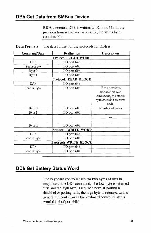
DBh Get Data from 5MBus Device
BIOS command DBh is written to I/O port 64h. If the previous transaction was successful, the status byte contains OOh.
Data Formats The data format for the protocols for DBh is:
CommandlData Destination Description Protocol: READ WORD
DBh I/O port 64h Status Byte I/O J:lort 60h
Byte 0 I/O port 60h Byte 1 I/O port 60h
Protocol: READ BLOCK DAh I/O port 64h
Status Byte I/O port 60h If the previous transaction was
erroneous, the status byte contains an error
code. Byte 0 1/0 jlort 60h Number of bytes Byte 1 1/0 port 60h
... ... ...
... ... . .. By ten I/O port 60h
Protocol: WRITE WORD DBh I/O port 64h
Status Byte I/O port 60h Protocol: WRITE BLOCK
DBh I/O port 64h Status Byte I/O jlort 60h
DOh Get Battery Status Word
The keyboard controller returns two bytes of data in response to the DDh command. The low byte is returned first and the high byte is returned next. If polling is disabled or polling fails, the high byte is returned with a general timeout error in the keyboard controller status word (bit 6 of port 64h).
Chapter 6 Smart Battery Support 51

Error Codes for Commands DAh, DBh, and DOh
The valid error codes for commands DAh and DBh are:
Error Code Description IOh Slave address not acknowledged llh device detected error/data byte not acknowledged ISh Timeout error 19h Unsupported protocol specified IAh 5MBus busy
Smart Battery Status Monitoring
AMIKey periodically polls for the smart battery status and verifies the status against the alarm conditions that are sent to the system BIOS (if alarm conditions are sent to the BIOS).
The keyboard controller sends the battery status command (l6h) to the smart battery once every Batt_Delay_time + 1 second, as long as Batt_Delay_time is a non-zero value. The battery responses are stored in keyboard controller RAM.
The high byte in the status word is checked to see if any alarm has been reported or if the previously reported alarm has been removed.
If either of these conditions exist and (depending on the alarm bits, and the mask status), the battery alarm task is executed.
52 AMIKey 38813 Keyboard Controller User's Guide
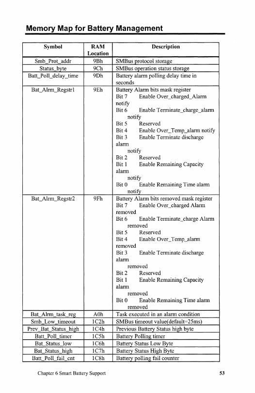
Memory Map for Battery Management
Symbol RAM Description Location
5mb Prot addr 9Bh 5MBus protocol storage Status byte 9Ch 5MBus operation status storage
Batt_Poll_delay _time 9Dh Battery alarm polling delay time in seconds
BaCAlrm_Regstr I 9Eh Battery Alarm bits mask register Bit 7 Enable Oveccharged_Alarm notify Bit 6 Enable Terminate3harge_alarm
notify Bit 5 Reserved Bit4 Enable OvecTemp_alarm notify Bit 3 Enable Terminate discharge alarm
notify Bit 2 Reserved Bit 1 Enable Remaining Capacity alarm
notify Bit 0 Enable Remaining Time alarm
notify BaCAlrm_Regstr2 9Fh Battery Alarm bits removed mask register
Bit 7 Enable Oveccharged Alarm removed Bit 6 Enable Terminate3harge Alarm
removed Bit 5 Reserved Bit 4 Enable OvecTemp_alarm removed Bit 3 Enable Terminate discharge alarm
removed Bit 2 Reserved Bit 1 Enable Remaining Capacity alarm
removed Bit 0 Enable Remaining Time alarm
removed Bat Alrm task reg AOh Task executed in an alarm condition 5mb Low timeout lC2h 5MBus timeout value( default=25ms)
Prev Bat Status high lC4h Previous Battery Status high byte Batt Poll timer lC5h Battery Polling timer Bat Status low IC6h Battery Status Low Byte Bat Status high lC7h Battery Status High Byte
Batt Poll fail cnt lC8h Battery polling fail counter
Chapter 6 Smart Battery Support 53

Symbol RAM Description Location
Batt Poll retry_ cnt lC9h Battery Polling retry counter (default 16) Poll finish flag IF5h Flag byte used for status report
5mbus_data_buffer lDOh- 5MBus buffer for data storage (35 bytes) lD2h
54 AMI Key 38813 Keyboard Controller User's Guide

Chapter 6 Smart Battery Support 55


Index
3 38813 Keyboard Controller Status
Register, 21 38813 RAM, 35
A Accessing M38813 RAM Locations,
32 American Megatrends BBS, iv Anykey wakeup, 6 Aux_config Register, 16 Auxiliary Device Commands, 31 Auxiliary Output Buffer Full, 21
B BAT. Reset the defaults and buffers,
30 Bat_Alrm_Regstrl,53 BaCAlrm_Regstr2, 53 Bat_Alrm_task_reg,53 BaCStatus_high, 53 Bat_Status_low, 53 BatCPolLdelay_time,53 BatCPolLfail_cnt, 53 Batt_PolLretry _cnt, 53 Batt_PolUimer, 53 Battery Management Memory
Map, 53 BBS, iv BIOS version number, 26
C CCB (3), 27 Character buffer, 13 Character buffer head pointer, 12 Character buffer tail pointer, 12 Command/Data, 21 Configure the memory access index,
26 Control Any Key Resume, 29 Controller command byte (CCB), 23 Controller status flags, 9 Copyright message, 26
Index
o DAh Send Data to an 5MBus
Device, 50 Data bits, 18 Data buffer, 18 Data for get interrupt function
number, 12 DBh Get Data from 5MBus Device,
51 DDh Get Battery Status Word, 51 Default Function-Shifted Key Matrix,
36 Delay Counter, 13 Disable Auxiliary Device, 23, 25, 31 Disable keyboard, 23, 25 Disable keyboard and set default
values, 30 Downloadable Features, 2
E Echo, 30 EISA support, 2 Emulated Port 1 data, 11 Enable auxiliary device, 25, 31 Enable Auxiliary OBF interrupt, 23 Enable keyboard, 25, 30 Enable Keyboard OBF Interrupt, 23 Enable password, 25 Error Codes for Commands DAh,
DBh, and DDh, 52 Error Reporting, 18 External and Internal Keyboards
Simultaneously, 4 External auxiliary devices, 2 External Keyboards, 1, 2, 4 External PS/2 Style Auxiliary
Devices, 4
F Fax, v Features, 1 FN hot key task storage register, 12 Fn Shifted Scan Codes, 42 Function key table, 2, 8, 33
57

Functions, 17 Functions hot keys, 7
G Gate A20 commands, 3 Gate A20 Support, 3 General hot keys, 7 General purpose register rl, 9 General purpose temporary register, 9 Get current contents of
MEM_INDEX, 26 Get interrupt function request, 28
H Help, iv Hot key Make/Break flags, 10 Hot key support, 2 Hot key 1 scan code storage, 10 Hot keys, 7 Hot pluggability, 2 Hot Pluggable PS/2 devices, 5 Hot Port Swapping, 5
I/O port 0060h., 20 I/O port 0064h, 20 IBM PC Compatibility Mode, 23 IBM PS/5S numeric keypads, 1 Inhibit override, 23 Inhibit Switch, 21 Input Buffer Full, 21 Interface test, 25 Internal and External Keyboard
Support, 35 Internal Auxiliary Device Support, 3 Internal auxiliary devices., 2 Internal keyboard matrix, 2, 8 Internal Keyboard Scan Code
Controller, 3 Internal keyboards, 2 Internal memory index register, 10 Internal Numeric Keypad Support, 3 Internet Address, v Invalid command, 31 IRQ12 line, 2 ISA support, 2
K KBC_FLAGS (Bits 7 and 6)., 32 Keyboard Command Status, 13
Keyboard commands, 25, 30 Keyboard Controller command byte,
10,23 Keyboard Controller Commands,
25 Keyboard Controller Functions, 17 Keyboard Inhibit, 19 Keyboard response counter, 10 Keyboard/Mouse status information,
12
L Last scanner character found, 12 LED and Control flags, 12 LED Support, 4 Load password, 25
M M38813 keyboard controller self test,
25 M38813 Special Function Registers,
9 Megakey,2 MEM_INDEX, 26, 32 Memory Map, 9 Mouse response counter, 9 Mouse Sampling Rate, 14 Mouse status information, 11
N Novell NetWare, 3 Numeric Keypad
Scan codes, 44
o Old character buffer, 10 Output Buffer Full, 21 Output next received byte of data
from system to auxiliary device, 26
p Parity
Keyboard data, 17 Parity bit, 18 Parity Error, 21 Password Pointer, 10 Password support, 2, 6 Pinout for M38813, 15 Poll input port high, 25
58 AMIKey 38813 Keyboard Controller User's Guide

Poll input port low, 25 Poll_fInish_flag, 53 Port swapping, 2 Power Management Support, 2 PoweCDown State (STOP mode, 28 Prev _Bat_Status_high, 53 PS/2 auxiliary devices, 1 PS/2 support, 2 Pulse Hot Keys, 7 Pulse only RC, 26
Q Quick Lock Support, 6
R RAM loaded function shift code
table, 14 Read data, 31 Read device type, 31 Read ID bytes, 30 Read input port, 25 Read Port 2, 26 Read test inputs, 26 Read the contents of the memory
location pointed by MEM_INDEX, 26
Read, Set, Clear, or Toggle port bits, 28
READ_BLOCK, 50 READ_WORD, 50 Resend,31 Resend the last transmission, 30 Reset, 31 Reset scaling, 31 Reset wrap mode, 31
s Scan code
Translation, 17 Scan Code Controller, 35 Scan Code Generation, 37 Scan Code Set 2 and 3,37 Scan code_3 set makelbreak variable,
14 Scan Codes
Special handling, 41 Scanner buffer, 13 Sc~nner buffer flag byte storage, 13 Scanner buffer pointer, 12 Scratch Register, 9
Index
Select alternate scan code set, 30 Send American Megatrends
copyright message, 26 Send controller BIOS version
number to the computer., 26
Send data back to the system, 26 Set all keys make only, 30 Set all keys makelbreak., 30 Set all keys typematic, 30 Set all keys typematic makelbreak, 30 Set default values, 31 Set defaults, 30 Set key type make only, 30 Set key type makelbreak., 30 Set key type typematic, 30 Set remote mode, 31 Set resolution, 31 Set sampling rate, 31 Set scaling, 31 Set stream mode, 31 Set the keyboard LEDs, 30 Set typematic delay and rate, 30 Set wrap mode, 3 1 Simultaneous External and Internal
Auxiliary Devices, 4 Smart Battery, 33 Smart Battery 5MBus Interface, 8 Smart Battery Status Monitoring,
52 Smart Battery Support, 49 5mb_Low_timeout,53 5mb_ProCaddr, 53 5MBus Protocols, 50 5MBus.,8 5mbus_data_buffer, 53 SMI,6 Special Handled Key Codes, 41 Special Handling Scan Codes and
Fn_Shiftable Keys, 41 Special Keyboard Controller
Commands, 26 Stack Pointer, 9 Standard Keyboard Controller
Commands, 25 Standard Scan Codes, 36 Start bit, 18 ST AT8042, 27 Status request, 31 Status_byte, 53
59

Stop bit, 18 STOP Mode, 6 System and Keyboard Controller
Command Interface, 20 System Flag, 21, 23 System Stack, 9
T Technical support, iv Temporary subroutine scratch
registers, 9 Test auxiliary device clock and data
(interface test XE "Interface test" ), 25
Test keyboard clock and data lines, 25
Test password installed, 25 Time-out bit, 18 Timeout Error, 21
Translation, 17 Typematic rate., 12
U User RAM, 10 User-defined scan code set_2 table,
14
W WAIT Mode, 5 Wakeup task storage register, 10 Web Site, v Windows, 3 Write Port 2, 26 Write the memory location pointed
by MEM_INDEX, 26 WRITE_BLOCK, 50 WRITE_WORD, 50
60 AMIKey 38813 Keyboard Controller User's Guide