Embed Size (px)
Citation preview

© 2006 American Standard inc. All Rights Reserved Pub. No. 22-1782-01
Product Data4TCC3018A through 4TCC3060ASingle Package Convertible Cooling13 SEER1½ - 5 TonR-410A
22-1782-01
Mar. 03, 2006

2
It's Hard to Stop a Trane.Single Package Cooling SystemTrane offers a complete family of cooling systems, designed to give you theunbeatable combination of energy efficiency and lower operating costs.
Introducing the new TRANE Single Package Cooling System.
Single Package Cooling Systems areeasy and versatile to install. Becausecooling and air handlingfunctions are allcontained in a single cabinet, a Tranepackage air conditioner is easy to installand service. It can be flush mountedbeside your home at ground level orplaced on the roof for horizontal ordownflow installation. When connected toan optional Trane thermostat control andair distribution ducts, you have a highlyefficient, total home comfort system.
Single Package Cooling Systemsprovide better performance. Oursingle package air conditioners offercooling efficiencies that are unmatchedin the industry and provide you with aproduct far superior in performance thanthe competition.
3
Contents
Optional Equipment Listing 4
General Data 5
Heater Data 8
SPEK Data 9
Performance Cooling Data 10
Typical Wiring 13
Optional Equipment 16
Dimensional Data 21
Mechanical Specifications 25

4
Optional Equipment ListingOPTIONAL EQUIPMENT FOR PACKAGED UNITS (check mark [✓✓✓✓✓ ] indicates accessories included)
Roof Curb Full Perimeter (4TCC3018-36A) 3 ................................................................... BAYCURB050A[ ]Roof Curb Full Perimeter (4TCC3042-60A) 3 ................................................................... BAYCURB051A[ ]Roof Curb Utility Extension Kit (BAYCURB050A) ................................................................. BAYUTIL101A[ ]Roof Curb Utility Extension Kit (BAYCURB051A) ................................................................. BAYUTIL102A[ ]0-25% Manual Fresh Air Damper (4TCC3018-36A) 1. ...................................................... BAYOSAH001A[ ]0-25% Manual Fresh Air Damper (4TCC3042-60A) 1. ...................................................... BAYOSAH002A[ ]Motorized Fresh Air Damper (4TCC3018-36A) 1. ............................................................ BAYDMPR101A[ ]Motorized Fresh Air Damper (4TCC3042-60A) 1. ............................................................. BAYDMPR102A[ ]16" Round Duct Adapter (2 per box) (4TCC3018-36A) 6 ................................................. BAYSQRD001A[ ]18" Round Duct Adapter (2 per box) (4TCC3018-60A) 6 ................................................. BAYSQRD002A[ ]0-100% Mod Economizer w/Baro. Relief (4TCC3018-36A) 124 .................................... BAYECON101B[ ]0-100% Mod. Economizer w/Baro. Relief (4TCC042-60A) 124. .................................... BAYECON102B[ ]0-100% Horizontal Economizer (4TCC3018-36A) 12 . .................................................... BAYECON200A[ ]0-100% Horizontal Economizer (4TCC3042-60A) 12 . .................................................... BAYECON201A[ ]Enthalpy Control for Economizer (solid state). .................................................................... BAYENTH001A[ ]Remote Potentiometer (All-BAYECON***A) ............................................................................ BAYSTAT023[ ]1"-2" Filter Frame (4TCC3018-36A) (20 x 20 filter not included) 1. .................................... BAYFLTR101A[ ]1"-2" Filter Frame (4TCC3042-60A) (20 x 20,20X18 filter not included) 1. ........................ BAYFLTR201A[ ]Evaporator Defrost Control (Low Ambient Cooling) Kit 5. ................................................. BAYLOAM011A[ ]Head Pressure Control (Low Ambient Cool) (208/240v) Kit 5. ......................................... BAYLOAM105A[ ]Quick Start Kit (4TCC3-A1) .................................................................................................. BAYKSKT301A[ ]Crankcase Heater Recip (4TCC3018A1)(230v) 5. ............................................................. BAYCCHT003A[ ]Crankcase Heater Scroll(4TCC3036,48,60A1/3)(230v) 5. ................................................. BAYCCHT202A[ ]Crankcase Heater (4TCC3036,48,60A4)(460v) 5. ............................................................. BAYCCHT203A[ ]Adapter Curb 4TCC3018-036A to BAYCURB030,38 ........................................................ BAYADAP050A[ ]Adapter Curb 4TCC3018-036A to BAYCURB033 ............................................................. BAYADAP051A[ ]Adapter Curb 4TCC3042-060A to BAYCURB030,38 ........................................................ BAYADAP052A[ ]Adapter Curb 4TCC3042-060A to BAYCURB033 ............................................................. BAYADAP053A[ ]Adapter Curb 4TCC3042-060A to BAYCURB034 ............................................................. BAYADAP054A[ ]12" Duct Shroud Covers Horizontal 4TCC3018-060A7. ................................................... BAYCOVR112A[ ]18" Duct Shroud Covers Horizontal 4TCC3018-060A 7. .................................................. BAYCOVR118A[ ]Extreme Condition Mounting Kit - All BAYCURB & BAYADAP ......................................... BAYEXMK001A[ ]Extreme Condition Mounting Kit - All BAYUTIL .................................................................. BAYEXMK002A[ ]Extreme Condition Mounting Kit - All Slab Mounts ............................................................. BAYEXMK003A[ ]Lifting Lug Kit .......................................................................................................................... BAYLlFT002B[ ]SUPPLEMENTARY HEATERS (1 PHASE)3.76/5.0 KW Heater (208/240V 1PH) (4TCC3018-060A1) ................................................. BAYHTRV105A[ ]7.50/10.0 KW Heater (208/240V 1PH) (4TCC3024-060A1) ............................................... BAYHTRV110A[ ]11.27/15.00 KW Heater (208/240V 1PH) (4TCC3030-060A1) ........................................... BAYHTRV115A[ ]15.0/20.0 KW Heater (208/240V 1PH) (4TCC3048-060A1) ............................................... BAYHTRV120A[ ]SUPPLEMENTARY HEATERS (3 PHASE)3.76/5.0 KW Heater (208/240V 3PH) (4TCC3018-060A3) ................................................. BAYHTRV305A[ ]7.50/10.0 KW Heater (208/240V 3PH) (4TCC3024-060A3) ............................................... BAYHTRV310A[ ]11.27/15.00 KW Heater (208/240V 3PH) (4TCC3030-060A3) ........................................... BAYHTRV315A[ ]15.00/20.0 KW Heater (208/240V 3PH) (4TCC3048-060A3) ............................................. BAYHTRV320A[ ]3.76/5.0 KW Heater (460V 3PH) (4TCC3018-060A4) ........................................................ BAYHTRV405A[ ]7.50/10.0 KW Heater (460V 3PH) (4TCC3024-060A4) ...................................................... BAYHTRV410A[ ]11.27/15.00 KW Heater (460V 3PH) (4TCC3030-060A4) .................................................. BAYHTRV415A[ ]15.00/20.0 KW Heater (460V 3PH) (4TCC3048-060A4) .................................................... BAYHTRV420A[ ]Single Power Entry Kit 8 . ...................................................................................................BAYSPEK060A[ ]Single Power Entry Kit 8 . ...................................................................................................BAYSPEK061A[ ]Single Power Entry Kit 8 . ...................................................................................................BAYSPEK062A[ ]Single Power Entry Kit 8 . ...................................................................................................BAYSPEK063A[ ]Single Power Entry Kit 8 . ...................................................................................................BAYSPEK064A[ ]Single Power Entry Kit 8 . ...................................................................................................BAYSPEK065A[ ]
NOTES: 1 Must use internal filter frame when economizer or fresh air kit is used.2 Dry bulb control standard with economizer.3 Ships knocked down.4 Downflow only.5 Low Ambient cooling requires crankcase heater (BAYCCHT----A).6 It is the responsibility of the installing dealer to properly size the ductwork for each specific application.7 BAYCOVR112,118A will not cover BAYSQRD002A applications.8 See table on page 8 for matching kit with units and heaters.

5
General Data
1Rated in accordance withA.R.I. Standard 210/240.Noise tested in accordancewith A.R.I. Standard 270.A.R.I. standard rating condi-tions are: 80 D.B. 67 W.B.entering air to indoor coil. 95D.B. entering air to outdoorcoil.
2 All models are UL Listed. Rat-ings shown are for elevationsup to 2000 ft. For higher el-evations reduce ratings at arate of 4% per 1000 ft. eleva-tion.
3 Convertible to LPG.
4 This value is approximate. Formore precise value, see UnitNameplate.
5 Based on U.S. GovernmentStandard Tests.
6 Filters must be installed inreturn air stream. Square foot-ages listed are based on 300f.p.m. face velocity. If perma-nent filters are used size permanufacturer's recommenda-tion with a clean resistance of0.05" W.C.
7 Unit is shipped on high input,unit is convertible to low inputwith a Low Fire accessory kit.
MODEL RATED Volts/Ph/Hz
RATINGS (COOLING) 1Indoor Airflow (CFM)Power Input (KW)EER/SEER (BTU/Watt-Hr)66666Sound Rating No. 22222
POWER CONN.—V/Ph/HzMin. Brch. Cir. Ampacity 33333Fuse Size—Max. /Recmd.(Amps)
COMPRESSORVolts/Ph/HzR.L. Amps—L.R. Amps
OUTDOOR COIL—TYPERows/F.P.I.Face Area (sq.ft.)Tube Size (in.)
INDOOR COIL—TYPERows/F.P.I.Face Area (sq.ft.)Tube Size (in.)Refrigerant ControlDrain Conn. Size (in.)
OUTDOOR FAN — TYPENo. Used/Dia. (in.)Type Drive/No. SpeedsMotor—HP / R.P.M.Volts/Ph/HzF.L. Amps—L.R. Amps
INDOOR FAN—TYPEDia x Width (in.)Drive / No. SpeedsMotor—HP / R.P.M.Volts/Ph/HzF.L. Amps—L.R. Amps
FILTER / FURNISHED?Type RecommendedMin. Face Area 77777(sq. ft.)
REFRIGERANTCharge (lbs.)
DIMENSIONSCrated (in.)
WEIGHTShipping (lbs.) / Net (lbs.)
4TCC3018A1000A208-230/1/60
180006751.6411/13
74208-230/1/60
10.115/15
200-230/1/606.41/38.6
SPINE FIN2/2410.063/8
PLATE FIN3/153.543/8
EXPANSION VALVE3/4 FEMALE NPT
PROPELLER1/23
DIRECT/11/12/810230/1/600.54/0.95
CENTRIFUGAL11 x 10
DIRECT/21/8/825
200-230/1/601/1.5NO
THROWAWAY2.0
(R-410A)5.94
H X W X D45.86X44.5X52.03
444/348
4TCC3024A1000A208-230/1/60
230007252.09
11/1376
208-230/1/6013.6
20/20
200-230/1/608.3/57.8
SPINE FIN2/24
10.063/8
PLATE FIN3/153.543/8
EXPANSION VALVE3/4 FEMALE NPT
PROPELLER1/23
DIRECT/11/12/810230/1/600.54/0.95
CENTRIFUGAL11 x 10
DIRECT/21/4/825
200-230/1/601.4/2.8
NOTHROWAWAY
2.67(R-410A)
5.8H X W X D
45.86X44.5X52.03
444/348
4TCC3030A1000A208-230/1/60
2800010002.6711/13
75208-230/1/60
21.735/35
208-230/1/6014.7/72.5
SPINE-FIN2/2410.063/8
PLATE FIN3/153.543/8
EXPANSION VALVE3/4 FEMALE NPT
PROPELLER1/23
DIRECT/11/5/830230/1/601.1/1.9
CENTRIFUGAL11 x 10
DIRECT/31/2/1080
200-230/1/602/4.4NO
THROWAWAY3.33
(R-410A)6.3
H X W X D45.86X44.5X52.03
445/349
4TCC3036A1000A208-230/1/60
3500012003.2911/13
76208-230/1/60
23.235/35
208-230/1/6015.4/83
SPINE FIN2/2410.06
3/8PLATE FIN
4/153.543/8
EXPANSION VALVE3/4 FEMALE NPT
PROPELLER1/23
DIRECT/10.2/830230/1/601.1/1.9
CENTRIFUGAL11 x 10
DIRECT/31/2/1075
200-230/1/602.9/5.8
NOTHROWAWAY
4.0(R-410A)
7.7H X W X D
5.86X44.5X52.03
460/364
4TCC3036A3000A208-230/3/60
3500012003.1811/13
76208-230/3/60
18.230/30
208-230/3/6011.5/77
SPINE FIN2/2410.06
3/8PLATE FIN
4/153.543/8
EXPANSION VALVE3/4 FEMALE NPT
PROPELLER1/23
DIRECT/11/5/830
230/1/601.1/1.9
CENTRIFUGAL10 x 10
DIRECT/31/2/1075
200-230/1/602.9/5.8
NOTHROWAWAY
4.0(R-410A)
7.7H X W X D
45.86X44.5X52.03
450/354

6
General Data
1Rated in accordance withA.R.I. Standard 210/240.Noise tested in accordancewith A.R.I. Standard 270.A.R.I. standard rating condi-tions are: 80 D.B. 67 W.B.entering air to indoor coil. 95D.B. entering air to outdoorcoil.
2 All models are UL Listed. Rat-ings shown are for elevationsup to 2000 ft. For higher el-evations reduce ratings at arate of 4% per 1000 ft. eleva-tion.
3 Convertible to LPG.
4 This value is approximate. Formore precise value, see UnitNameplate.
5 Based on U.S. GovernmentStandard Tests.
6 Filters must be installed inreturn air stream. Square foot-ages listed are based on 300f.p.m. face velocity. If perma-nent filters are used size permanufacturer's recommenda-tion with a clean resistance of0.05" W.C.
7 Unit is shipped on high input,unit is convertible to low inputwith a Low Fire accessory kit.
MODEL RATED Volts/Ph/Hz
RATINGS (COOLING) 1Indoor Airflow (CFM)Power Input (KW)EER/SEER (BTU/Watt-Hr)66666Sound Rating No. 22222
POWER CONN.—V/Ph/HzMin. Brch. Cir. Ampacity 33333Fuse Size—Max. /Recmd.(Amps)
COMPRESSORVolts/Ph/HzR.L. Amps—L.R. Amps
OUTDOOR COIL—TYPERows/F.P.I.Face Area (sq.ft.)Tube Size (in.)
INDOOR COIL—TYPERows/F.P.I.Face Area (sq.ft.)Tube Size (in.)Refrigerant ControlDrain Conn. Size (in.)
OUTDOOR FAN — TYPENo. Used/Dia. (in.)Type Drive/No. SpeedsMotor—HP / R.P.M.Volts/Ph/HzF.L. Amps—L.R. Amps
INDOOR FAN—TYPEDia x Width (in.)Drive / No. SpeedsMotor—HP / R.P.M.Volts/Ph/HzF.L. Amps—L.R. Amps
FILTER / FURNISHED?Type RecommendedMin. Face Area 77777(sq. ft.)
REFRIGERANTCharge (lbs.)
DIMENSIONSCrated (in.)
WEIGHTShipping (lbs.) / Net (lbs.)
4TCC3036A4000A460/3/60
3500012003.29
11/1376
460/3/608.7
15/15
460/3/605.13/35
SPINE FIN2/24
10.063/8
PLATE FIN4/153.543/8
EXPANSION VALVE3/4 FEMALE NPT
PROPELLER1/23
DIRECT/11/5/830230/1/600.6/1.3
CENTRIFUGAL10 x 10
DIRECT/21/2/ 1075460/1/601.7/3.12
NOTHROWAWAY
4.0(R-410A)
7.7H X W X D
45.86X44.5X52.03
450/354
4TCC3042A1000A208-230/1/60
4000014503.95
11/1378
208-230/1/6027.9
45/45
208-230/1/6019.2/104
SPINE FIN2/24
13.403/8
PLATE FIN3/15
53/8
EXPANSION VALVE3/4 FEMALE NPT
PROPELLER1/27.6
DIRECT/11/4/825230/1/601.4/3.5
CENTRIFUGAL10 x 10
DIRECT/31/2/ 1075
200-230/1/602.5/3.2
NOTHROWAWAY
4.67(R-410A)
8.1H X W X D
47.86X47.4X61.75
523/395
4TCC3048A1000A208-230/1/60
4650016004.23
11/1380
208-230/1/6031.1
50/50
208-230/1/6020.5/109
SPINE FIN2/2413.43/8
PLATE FIN3/15
53/8
EXPANSION VALVE3/4 FEMALE NPT
PROPELLER1/27.6
DIRECT/11/4/825230/1/601.4/3.5
CENTRIFUGAL10 x 10
DIRECT/33/4/ 1080
200-230/1/604/8.4NO
THROWAWAY5.33
(R-410A)8.2
H X W X D47.86X47.4X61.75
607/479
4TCC3048A3000A208-230/3/60
4650016004.23
11/1380
208-230/3/6023.6
35/35
208-230/3/6014.6/91
SPINE FIN2/2413.43/8
PLATE FIN3/15
53/8
EXPANSION VALVE3/4 FEMALE NPT
PROPELLER1/27.6
DIRECT/11/4/825230/1/601.4/3.5
CENTRIFUGAL10 x 10
DIRECT/33/4/1080
200-230/1/604/8.4NO
THROWAWAY5.33
(R-410A)8.2
H X W X D47.86X47.4X61.75
607/479
4TCC3048A4000A460/3/60
4650016004.23
11/1380
460/3/6011.7
15/15
460/3/607.05/46
SPINE FIN2/2413.43/8
PLATE FIN3/15
53/8
EXPANSION VALVE3/4 FEMALE NPT
PROPELLER1/27.6
DIRECT/11/4/825460/1/600.74/1.6
CENTRIFUGAL10 x 10
DIRECT/23/4/1080460/1/602.2/4.36
NOTHROWAWAY
5.33(R-410)
8.2H X W X D
47.86X47.4X61.75
607/479

7
General Data
1Rated in accordance withA.R.I. Standard 210/240.Noise tested in accordancewith A.R.I. Standard 270.A.R.I. standard rating condi-tions are: 80 D.B. 67 W.B.entering air to indoor coil. 95D.B. entering air to outdoorcoil.
2 All models are UL Listed. Rat-ings shown are for elevationsup to 2000 ft. For higher el-evations reduce ratings at arate of 4% per 1000 ft. eleva-tion.
3 Convertible to LPG.
4 This value is approximate. Formore precise value, see UnitNameplate.
5 Based on U.S. GovernmentStandard Tests.
6 Filters must be installed inreturn air stream. Square foot-ages listed are based on 300f.p.m. face velocity. If perma-nent filters are used size permanufacturer's recommenda-tion with a clean resistance of0.05" W.C.
7 Unit is shipped on high input,unit is convertible to low inputwith a Low Fire accessory kit.
MODEL RATED Volts/Ph/Hz
RATINGS (COOLING) 1Indoor Airflow (CFM)Power Input (KW)EER/SEER (BTU/Watt-Hr)66666Sound Rating No. 22222
POWER CONN.—V/Ph/HzMin. Brch. Cir. Ampacity 33333Fuse Size—Max. /Recmd.(Amps)
COMPRESSORVolts/Ph/HzR.L. Amps—L.R. Amps
OUTDOOR COIL—TYPERows/F.P.I.Face Area (sq.ft.)Tube Size (in.)
INDOOR COIL—TYPERows/F.P.I.Face Area (sq.ft.)Tube Size (in.)Refrigerant ControlDrain Conn. Size (in.)
OUTDOOR FAN — TYPENo. Used/Dia. (in.)Type Drive/No. SpeedsMotor—HP / R.P.M.Volts/Ph/HzF.L. Amps—L.R. Amps
INDOOR FAN—TYPEDia x Width (in.)Drive / No. SpeedsMotor—HP / R.P.M.Volts/Ph/HzF.L. Amps—L.R. Amps
FILTER / FURNISHED?Type RecommendedMin. Face Area 77777(sq. ft.)
REFRIGERANTCharge (lbs.)
DIMENSIONSCrated (in.)
WEIGHTShipping (lbs.) / Net (lbs.)
4TCC3060A1000A208-230/1/60
5800018005.27
11/1379
208-230/1/6043.5
60/60
208-230/1/6027.6/158
SPINE FIN2/24
13.843/8
PLATE FIN4/15
53/8
EXPANSION VALVE3/4 FEMALE NPT
PROPELLER1/27.6
DIRECT/11/4/825230/1/601.4/3.5
CENTRIFUGAL11 x 10
DIRECT/31/1075
208-230/1/607.6/7.6
NOTHROWAWAY
6.67(R-410A)
10H X W X D
49.86X47.4X61.75
610/482
4TCC3060A3000A208-230/3/60
5800018005.27
11/ 13.079
208-230/3/6031.7
50/50
208-230/3/6018.1/137
SPINE FIN2 / 2413.843/8
PLATE FIN4 / 15
53/8
EXPANSION VALVE3/4 FEMALE NPT
PROPELLER1 / 27.6
DIRECT / 11/4 / 825230/1/601.4 /3.5
CENTRIFUGAL11 X 10
DIRECT/31 / 1075
208-230/1/607.6/7.6
NOTHROWAWAY
6.67(R-410A)
10H X W X D
49.86 X 47.4 X 61.75
610 / 482
4TCC3060A4000A460/3/605800018005.27
11 / 13.079
460/3/6019.5
25/25
460/3/608.97/62
SPINE FIN2 / 2413.843/8
PLATE FIN4/ 15
53/8
EXPANSION VALVE3/4 FEMALE NPT
PROPELLER1 / 27.6
DIRECT / 11/4 / 825460/1/600.74 /1.6
CENTRIFUGAL11 X 10
DIRECT/31 / 1075
208-230/1/607.6/7.6
NOTHROWAWAY
6.67(R-410A)
10H X W X D
49.86 X 47.4 X 61.75
610 / 482

8
UNITMODEL
ELECTRICHEATERMODEL
RATEDVOLTAGE PHASE AMPS
HEATER CAPACITYNO. OFSTAGES
KW / STAGE
MCA (2)
MAX.FUSE
OR HQCRCKT BKRSIZE (4)
CANADAONLY MAX.CKT BKRSIZE (5)KW BTUH 1 2
^W/TC*3018A1 BAYHTRV105A 208/240 1 18/21 3.76/5.0 12800/17100 1 3.76/5.0 23/26 25/30 25/30
^W/TC*3024A1BAYHTRV105A 208/240 1 18/21 3.76/5.0 12800/17100 1 3.76/5.0 23/26 25/30 25/30
BAYHTRV110A 208/240 1 36/42 7.50/10.0 25600/34100 1 7.50/10.0 45/52 45/60 45/60
^W/TC*3030A1^W/TC*3036A1^W/TC*3042A1
BAYHTRV105A 208/240 1 18/21 3.76/5.0 12800/17100 1 3.76/5.0 23/26 25/30 25/30
BAYHTRV110A 208/240 1 36/42 7.50/10.0 25600/34100 1 7.50/10.0 45/52 45/60 45/60
BAYHTRV115A# 208/240 1 54/63 11.27/15.0 38500/51200 2 7.50/10.0 3.76/5.0 68/78 70/80 70/80
^W/TC*3048A1^W/TC*3060A1
BAYHTRV105A 208/240 1 18/21 3.76/5.0 12800/17100 1 3.76/5.0 23/26 25/30 25/30
BAYHTRV110A 208/240 1 36/42 7.50/10.0 25600/34100 1 7.50/10.0 45/52 45/60 45/60
BAYHTRV115A# 208/240 1 54/63 11.27/15.0 38500/51200 2 7.50/10.0 3.76/5.0 68/78 70/80 70/80
BAYHTRV120A# 208/240 1 72/83 15.00/20.0 51200/68300 2 7.50/10.0 7.50/10.0 90/104 90/110 90/110
^W/TC*3036A3
BAYHTRV305A 208/240 3 10/12 3.76/5.0 12800/17100 1 3.76/5.0 13/15 15/15 15/15
BAYHTRV310A 208/240 3 21/24 7.50/10.0 25600/34100 1 7.50/10.0 26/30 30/30 30/30
BAYHTRV315A 208/240 3 31/36 11.27/15.0 38500/51200 2 7.50/10.0 3.76/5.0 39/45 40/45 40/45
^W/TC*3048A3^W/TC*3060A3
BAYHTRV305A 208/240 3 10/12 3.76/5.0 12800/17100 1 3.76/5.0 13/15 15/15 15/15
BAYHTRV310A 208/240 3 21/24 7.50/10.0 25600/34100 1 7.50/10.0 26/30 30/30 30/30
BAYHTRV315A 208/240 3 31/36 11.27/15.0 38500/51200 2 7.50/10.0 3.76/5.0 39/45 40/45 40/45
BAYHTRV320A 208/240 3 42/48 15.00/20.0 51200/68300 2 7.50/10.0 7.50/10.0 52/60 60/60 60/60
^W/TC*3036A4
BAYHTRV405A 480 3 6 5 17100 1 5 8 15 15
BAYHTRV410A 480 3 12 10 34100 1 10 15 15 15
BAYHTRV415A 480 3 18 15 51200 2 10 5 23 25 25
^W/TC*3048A4^W/TC*3060A4
BAYHTRV405A 480 3 6 5 17100 1 5 8 15 15
BAYHTRV410A 480 3 12 10 34100 1 10 15 15 15
BAYHTRV415A 480 3 18 15 51200 2 10 5 23 25 25
BAYHTRV420A 480 3 24 20 68300 2 10 10 30 30 30
Heater Data
NOTES:
1. Any power supply and circuits must be wired and protected in accordance with local electrical codes. (2) The MCA values listed are for electric heater only. 3. Field wire must be rated at least 75°C (4) The HACR circuit breaker is for U.S.A. installations only. (5) For Canada installation reference only. * Heater uses fuses.
4TCC3018A to 4TCC3060A Heater Data

9
Single Power Entry Kit Data
SPEK 4TCC3018A to 4TCC3060A
NOITCETORPTNERRUCREVODNAYTICAPMAREWOPTIUCRICELGNISELGNISREWOPYRTNE
TIK
RETAEHLEDOM
TINULEDOM
NIMTKCPMA
XAM-REVO
TNERRUCECIVED
ELGNISREWOPYRTNE
TIK
RETAEHLEDOM
TINULEDOM
NIMTKCPMA
XAM-REVO
TNERRUCECIVED
060KEPSYAB
A501VRTHYAB
1A8103*CT4 72 03
#A360KEPSYAB
A511VRTHYAB
1A0303*CT4 18 09
1A4203*CT4 82 03 1A6303*CT4 28 09
1A0303*CT4 92 53 1A2403*CT4 18 09
1A6303*CT4 03 53 1A8403*CT4 38 09
1A2403*CT4 92 54 1A0603*CT4 88 09
1A8403*CT4 13 05A021VRTHYAB
1A8403*CT4 901 011
A011VRTHYAB
1A4203*CT4 45 06 1A0603*CT4 411 521
1A0303*CT4 55 06#A460KEPSYAB A023VRTHYAB
3A8403*CT4 56 07
1A6303*CT4 65 06 3A0603*CT4 07 07
1A2403*CT4 55 06
1A8403*CT4 75 06
A160KEPSYAB
A503VRTHYAB
3A6303*CT4 81 03
3A8403*CT4 42 53
3A0603*CT4 23 54
A013VRTHYAB
3A6303*CT4 33 53
3A8403*CT4 53 53
3A0603*CT4 04 54
A513VRTHYAB
3A6303*CT4 84 05
3A8403*CT4 05 05
3A0603*CT4 55 06
A504VRTHYAB
4A6303*CT4 01 51
4A8403*CT4 21 51
4A0603*CT4 02 52
A014VRTHYAB
4A6303*CT4 71 02
4A8403*CT4 81 02
4A0603*CT4 52 52
A514VRTHYAB
4A6303*CT4 52 52
4A8403*CT4 52 52
4A0603*CT4 23 53
A024VRTHYAB4A8403*CT4 33 53
4A0603*CT4 04 04
#A260KEPSYABA501VRTHYAB 1A0603*CT4 44 07
A011VRTHYAB 1A0603*CT4 26 07
.retaehro/dnatinurofderiuqerfideilppuserasesufrewoPtiucriCelgniS# 2&10P452239C12.gwDmorF
10
Performance Data Cooling
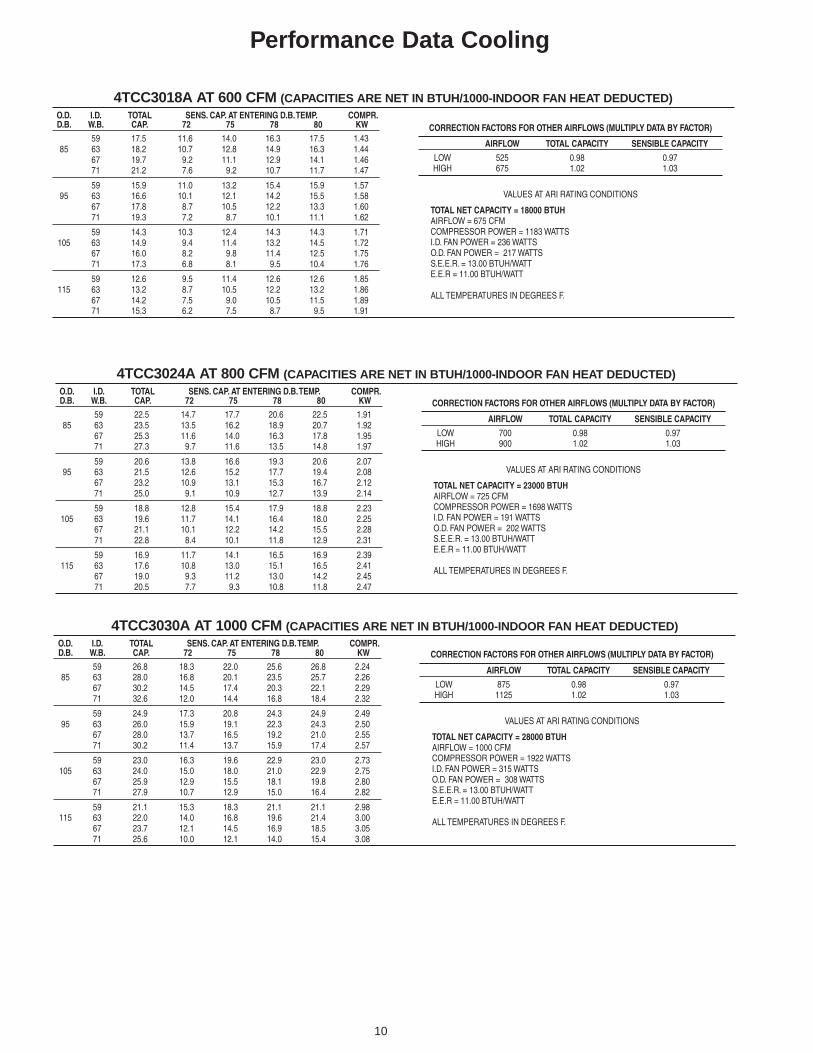
4TCC3018A AT 600 CFM (CAPACITIES ARE NET IN BTUH/1000-INDOOR FAN HEAT DEDUCTED)O.D. I.D. TOTAL SENS. CAP. AT ENTERING D.B. TEMP. COMPR.D.B. W.B. CAP. 72 75 78 80 KW
59 17.5 11.6 14.0 16.3 17.5 1.4385 63 18.2 10.7 12.8 14.9 16.3 1.44
67 19.7 9.2 11.1 12.9 14.1 1.4671 21.2 7.6 9.2 10.7 11.7 1.47
59 15.9 11.0 13.2 15.4 15.9 1.5795 63 16.6 10.1 12.1 14.2 15.5 1.58
67 17.8 8.7 10.5 12.2 13.3 1.6071 19.3 7.2 8.7 10.1 11.1 1.62
59 14.3 10.3 12.4 14.3 14.3 1.71105 63 14.9 9.4 11.4 13.2 14.5 1.72
67 16.0 8.2 9.8 11.4 12.5 1.7571 17.3 6.8 8.1 9.5 10.4 1.76
59 12.6 9.5 11.4 12.6 12.6 1.85115 63 13.2 8.7 10.5 12.2 13.2 1.86
67 14.2 7.5 9.0 10.5 11.5 1.8971 15.3 6.2 7.5 8.7 9.5 1.91
CORRECTION FACTORS FOR OTHER AIRFLOWS (MULTIPLY DATA BY FACTOR)
AIRFLOW TOTAL CAPACITY SENSIBLE CAPACITY
LOW 525 0.98 0.97HIGH 675 1.02 1.03
VALUES AT ARI RATING CONDITIONS
TOTAL NET CAPACITY = 18000 BTUHAIRFLOW = 675 CFMCOMPRESSOR POWER = 1183 WATTSI.D. FAN POWER = 236 WATTSO.D. FAN POWER = 217 WATTSS.E.E.R. = 13.00 BTUH/WATTE.E.R = 11.00 BTUH/WATT
ALL TEMPERATURES IN DEGREES F.
4TCC3024A AT 800 CFM (CAPACITIES ARE NET IN BTUH/1000-INDOOR FAN HEAT DEDUCTED)O.D. I.D. TOTAL SENS. CAP. AT ENTERING D.B. TEMP. COMPR.D.B. W.B. CAP. 72 75 78 80 KW
59 22.5 14.7 17.7 20.6 22.5 1.9185 63 23.5 13.5 16.2 18.9 20.7 1.92
67 25.3 11.6 14.0 16.3 17.8 1.9571 27.3 9.7 11.6 13.5 14.8 1.97
59 20.6 13.8 16.6 19.3 20.6 2.0795 63 21.5 12.6 15.2 17.7 19.4 2.08
67 23.2 10.9 13.1 15.3 16.7 2.1271 25.0 9.1 10.9 12.7 13.9 2.14
59 18.8 12.8 15.4 17.9 18.8 2.23105 63 19.6 11.7 14.1 16.4 18.0 2.25
67 21.1 10.1 12.2 14.2 15.5 2.2871 22.8 8.4 10.1 11.8 12.9 2.31
59 16.9 11.7 14.1 16.5 16.9 2.39115 63 17.6 10.8 13.0 15.1 16.5 2.41
67 19.0 9.3 11.2 13.0 14.2 2.4571 20.5 7.7 9.3 10.8 11.8 2.47
CORRECTION FACTORS FOR OTHER AIRFLOWS (MULTIPLY DATA BY FACTOR)
AIRFLOW TOTAL CAPACITY SENSIBLE CAPACITY
LOW 700 0.98 0.97HIGH 900 1.02 1.03
VALUES AT ARI RATING CONDITIONS
TOTAL NET CAPACITY = 23000 BTUHAIRFLOW = 725 CFMCOMPRESSOR POWER = 1698 WATTSI.D. FAN POWER = 191 WATTSO.D. FAN POWER = 202 WATTSS.E.E.R. = 13.00 BTUH/WATTE.E.R = 11.00 BTUH/WATT
ALL TEMPERATURES IN DEGREES F.
4TCC3030A AT 1000 CFM (CAPACITIES ARE NET IN BTUH/1000-INDOOR FAN HEAT DEDUCTED)O.D. I.D. TOTAL SENS. CAP. AT ENTERING D.B. TEMP. COMPR.D.B. W.B. CAP. 72 75 78 80 KW
59 26.8 18.3 22.0 25.6 26.8 2.2485 63 28.0 16.8 20.1 23.5 25.7 2.26
67 30.2 14.5 17.4 20.3 22.1 2.2971 32.6 12.0 14.4 16.8 18.4 2.32
59 24.9 17.3 20.8 24.3 24.9 2.4995 63 26.0 15.9 19.1 22.3 24.3 2.50
67 28.0 13.7 16.5 19.2 21.0 2.5571 30.2 11.4 13.7 15.9 17.4 2.57
59 23.0 16.3 19.6 22.9 23.0 2.73105 63 24.0 15.0 18.0 21.0 22.9 2.75
67 25.9 12.9 15.5 18.1 19.8 2.8071 27.9 10.7 12.9 15.0 16.4 2.82
59 21.1 15.3 18.3 21.1 21.1 2.98115 63 22.0 14.0 16.8 19.6 21.4 3.00
67 23.7 12.1 14.5 16.9 18.5 3.0571 25.6 10.0 12.1 14.0 15.4 3.08
CORRECTION FACTORS FOR OTHER AIRFLOWS (MULTIPLY DATA BY FACTOR)
AIRFLOW TOTAL CAPACITY SENSIBLE CAPACITY
LOW 875 0.98 0.97HIGH 1125 1.02 1.03
VALUES AT ARI RATING CONDITIONS
TOTAL NET CAPACITY = 28000 BTUHAIRFLOW = 1000 CFMCOMPRESSOR POWER = 1922 WATTSI.D. FAN POWER = 315 WATTSO.D. FAN POWER = 308 WATTSS.E.E.R. = 13.00 BTUH/WATTE.E.R = 11.00 BTUH/WATT
ALL TEMPERATURES IN DEGREES F.

11
Performance Data Cooling
4TCC3048A AT 1600 CFM (CAPACITIES ARE NET IN BTUH/1000-INDOOR FAN HEAT DEDUCTED)O.D. I.D. TOTAL SENS. CAP. AT ENTERING D.B. TEMP. COMPR.D.B. W.B. CAP. 72 75 78 80 KW
59 43.8 29.8 35.8 41.7 43.8 3.7485 63 45.6 27.3 32.9 38.3 41.9 3.76
67 49.2 23.6 28.3 33 36.1 3.8271 53.1 19.6 23.5 27.4 30.0 3.86
59 41.4 28.8 34.6 40.3 41.4 4.1395 63 43.2 26.4 31.7 37.0 40.4 4.16
67 46.5 22.8 27.4 31.9 34.9 4.2371 50.2 18.9 22.7 26.5 28.9 4.27
59 39.0 27.7 33.3 38.8 39.0 4.53105 63 40.7 25.4 30.5 35.6 38.9 4.55
67 43.8 21.9 26.3 30.7 33.6 4.6371 47.3 18.2 21.9 25.5 27.8 4.67
59 36.6 26.5 31.9 36.6 36.6 4.92115 63 38.2 24.3 29.2 34.1 37.3 4.95
67 41.2 21.0 25.2 29.4 32.1 5.0371 44.5 17.4 20.9 24.4 26.7 5.08
CORRECTION FACTORS FOR OTHER AIRFLOWS (MULTIPLY DATA BY FACTOR)
AIRFLOW TOTAL CAPACITY SENSIBLE CAPACITY
LOW 1400 0.98 0.97HIGH 1800 1.02 1.03
VALUES AT ARI RATING CONDITIONS
TOTAL NET CAPACITY = 46500 BTUHAIRFLOW = 1600 CFMCOMPRESSOR POWER = 3330 WATTSI.D. FAN POWER = 583 WATTSO.D. FAN POWER = 314 WATTSS.E.E.R. = 13.00 BTUH/WATTE.E.R = 11.00 BTUH/WATT
ALL TEMPERATURES IN DEGREES F.
4TCC3042A AT 1400 CFM (CAPACITIES ARE NET IN BTUH/1000-INDOOR FAN HEAT DEDUCTED)O.D. I.D. TOTAL SENS. CAP. AT ENTERING D.B. TEMP. COMPR.D.B. W.B. CAP. 72 75 78 80 KW
59 38.1 25.6 30.7 35.8 38.1 3.1785 63 39.8 23.5 28.2 32.9 35.9 3.19
67 42.9 20.2 24.3 28.4 31.0 3.2471 46.3 16.8 20.2 23.5 25.7 3.27
59 35.5 24.6 29.5 34.4 35.5 3.5395 63 37.0 22.5 27.1 31.6 34.5 3.55
67 39.9 19.4 23.4 27.2 29.8 3.6171 43.1 16.1 19.4 22.6 24.7 3.65
59 32.9 23.4 28.2 32.8 32.9 3.89105 63 34.3 21.5 25.8 30.1 32.9 3.92
67 36.9 18.6 22.3 26 28.4 3.9871 39.9 15.4 18.5 21.6 23.6 4.02
59 30.2 22.2 26.7 30.2 30.2 4.26115 63 31.5 20.4 24.5 28.5 31.2 4.28
67 33.9 17.6 21.1 24.6 26.9 4.3571 36.6 14.6 17.5 20.4 22.3 4.40
CORRECTION FACTORS FOR OTHER AIRFLOWS (MULTIPLY DATA BY FACTOR)
AIRFLOW TOTAL CAPACITY SENSIBLE CAPACITY
LOW 1225 0.98 0.97HIGH 1575 1.02 1.03
VALUES AT ARI RATING CONDITIONS
TOTAL NET CAPACITY = 40000 BTUHAIRFLOW = 1450 CFMCOMPRESSOR POWER = 3009 WATTSI.D. FAN POWER = 518 WATTSO.D. FAN POWER = 109 WATTSS.E.E.R. = 13.00 BTUH/WATTE.E.R = 11.00 BTUH/WATT
ALL TEMPERATURES IN DEGREES F.
4TCC3036A AT 1200 CFM (CAPACITIES ARE NET IN BTUH/1000-INDOOR FAN HEAT DEDUCTED)O.D. I.D. TOTAL SENS. CAP. AT ENTERING D.B. TEMP. COMPR.D.B. W.B. CAP. 72 75 78 80 KW
59 33.6 22.6 27.2 31.7 33.6 2.8085 63 35.0 20.8 25.0 29.1 31.8 2.82
67 37.8 17.9 21.5 25.1 27.5 2.8671 40.8 14.9 17.9 20.8 22.8 2.89
59 31.2 21.6 26.0 30.3 31.2 3.1195 63 32.5 19.9 23.9 27.8 30.4 3.13
67 35.0 17.1 20.6 24.0 26.3 3.1871 37.8 14.2 17.1 19.9 21.8 3.21
59 28.7 20.5 24.7 28.7 28.7 3.42105 63 29.9 18.9 22.7 26.4 28.9 3.44
67 32.2 16.3 19.6 22.8 24.9 3.5071 34.8 13.5 16.2 18.9 20.7 3.53
59 26.2 19.3 23.3 26.2 26.2 3.74115 63 27.3 17.8 21.3 24.9 27.2 3.76
67 29.5 15.3 18.4 21.5 23.5 3.8271 31.8 12.7 15.3 17.8 19.5 3.86
CORRECTION FACTORS FOR OTHER AIRFLOWS (MULTIPLY DATA BY FACTOR)
AIRFLOW TOTAL CAPACITY SENSIBLE CAPACITY
LOW 1050 0.98 0.97HIGH 1350 1.02 1.03
VALUES AT ARI RATING CONDITIONS
TOTAL NET CAPACITY = 35000 BTUHAIRFLOW = 1200 CFMCOMPRESSOR POWER = 2556 WATTSI.D. FAN POWER = 420 WATTSO.D. FAN POWER = 206 WATTSS.E.E.R. = 13.00 BTUH/WATTE.E.R = 11.00 BTUH/WATT
ALL TEMPERATURES IN DEGREES F.
12
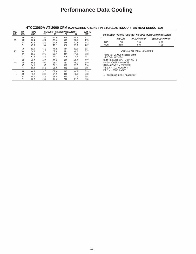
Performance Data Cooling
4TCC3060A AT 2000 CFM (CAPACITIES ARE NET IN BTUH/1000-INDOOR FAN HEAT DEDUCTED)O.D. I.D. TOTAL SENS. CAP. AT ENTERING D.B. TEMP. COMPR.D.B. W.B. CAP. 72 75 78 80 KW
59 56.0 35.7 42.9 50.0 54.6 4.7285 63 58.4 32.7 39.4 45.9 50.1 4.75
67 62.9 28.3 34.0 39.6 43.3 4.8271 67.9 23.4 28.2 32.8 35.9 4.87
59 52.1 34.3 41.2 48.1 52.1 5.2495 63 54.3 31.5 37.8 44.1 48.2 5.27
67 58.5 27.2 32.7 38.1 41.6 5.3671 63.2 22.5 27.1 31.6 34.5 5.41
59 48.2 32.8 39.4 45.9 48.2 5.77105 63 50.2 30.1 36.1 42.1 46.0 5.80
67 54.1 25.9 31.2 36.3 39.7 5.9071 58.4 21.5 25.9 30.2 33.0 5.95
59 44.3 31.0 37.3 43.5 44.3 6.29115 63 46.2 28.5 34.2 39.9 43.6 6.33
67 49.7 24.6 29.6 34.4 37.7 6.4471 53.7 20.4 24.5 28.6 31.2 6.50
CORRECTION FACTORS FOR OTHER AIRFLOWS (MULTIPLY DATA BY FACTOR)
AIRFLOW TOTAL CAPACITY SENSIBLE CAPACITY
LOW 1750 0.98 0.97HIGH 2250 1.02 1.03
VALUES AT ARI RATING CONDITIONS
TOTAL NET CAPACITY = 58000 BTUHAIRFLOW = 1800 CFMCOMPRESSOR POWER = 4391 WATTSI.D. FAN POWER = 595 WATTSO.D. FAN POWER = 287 WATTSS.E.E.R. = 13.00 BTUH/WATTE.E.R = 11.00 BTUH/WATT
ALL TEMPERATURES IN DEGREES F.

13
Typical Field Wiring
COMMONFAN
COMPRSSOR1ST STAGE ELECTRIC HEAT
2ND STAGE ELECTRIC HEATSWITCHOVER VALVE
DEFROST CONTROL 'T' SIGNAL
24 VOLTS
BGY
W1W2OTR
UNIT LOW VOLTAGE AREA
TYPICAL THERMOSTAT
UNIT HEATER AREA
ELECTRICHEATERCONTROLBOX
POLARIZEDPLUG
UNIT CONTROL BOX
3 PHPOWERUNIT
NOTE 1,8
3 PHPOWERHEATER
1 PHPOWER
1 PHPOWER
UNIT CONTROLBOX
UNIT HEATER AREA
FACTORY PROVIDEDFIELD CONNECTEDWIRES
(BL)
(YL)
(GR)
(PR)
(OR)
(OR)
B
G
Y
W1W2
O
T
R
(BR)
(RD)
(GR)
(BL)
(WH)(WH)
(YL)
(OR)
1 PHPOWER
3 PHPOWER
GROUNDWIRE
SINGLE POWR ENTRY
W1W2
(WH)(WH)
W1
W2
(WH)
(WH)
HEATER SECOND STAGE AMBIENTTEMPERATURE LOCKOUTNOTE 7,8
UNIT LOWVOLTAGEAREA
OUTDOORTHERMOSTATACCESSORYBAYSTAT033A
NOTE 10
HEATER AMBIENTTEMPERATURE LOCKOUTNOTE 7,8
UNIT LOWVOLTAGEAREA
OUTDOORTHERMOSTATACCESSORYBAYSTAT033A
NOTE 10
TYPICAL THERMOSTATTYPICAL THERMOSTAT
TYPICAL 2-STAGE THERMOSTAT
UNIT LOWVOLTAGE AREA
UNIT LOWVOLTAGE AREA
TO COMPR.CONTACTOR
ELECTRICHEATERCONTROLBOX
HEATERFUSES
UNITFUSES
SPEACCESSORYKIT
TO ECONOMIZERFACTORY PROVIDEDFIELD INSTALLED WIRES
NOTE 9
(NOT APPLICABLE TO THE WCM---F MODELS)
FIG. 3 OUTDOOR THERMOSTAT ACCESSORY CONNECTIONS
FIG. 1 SINGLE POWER ENTRY ACCESSORY CONNECTIONS FIG. 2 ECONOMIZER ACCESSORYCONNECTIONS
GROUNDWIRE
SEE SPEK INSTALLER'S GUIDEFOR ALL OTHER EXAMPLES
14
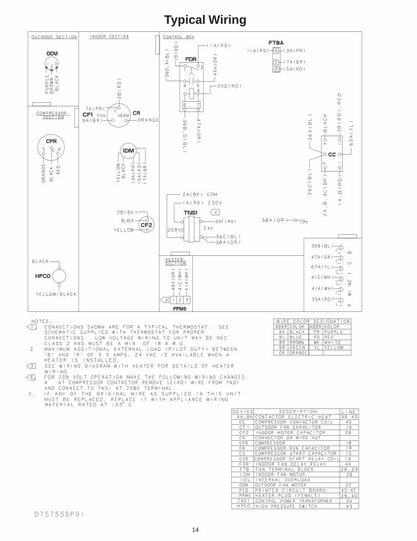
Typical Wiring

15
Typical Wiring
From Dwg. 21D757165 P02

16
Optional Equipment
BAYECON101,102A Down Discharge Economizer and Rain Hood(Mounts Over Horizontal Return Air Opening)
A
B
C
Economizer
Gaskets (2)
Rain HoodDuct
BAYCON200,201A Horizontal Economizer and Rain Hood
rezimonocE sledoMnoitacilppAtinU A B C
AA002NOCEYABA630-8103CW,CY4/2
A630-8103*CT4"00.22 "00.02 "78.61
AA102NOCEYABA060-2403CW,CY4/2
A060-2403*CT4"00.42 "56.22 "00.91
rezimonocE sledoMnoitacilppAtinU A
A101NOCEYAB A630-8103CW,CY4/2A630-8103*CT4
"521.02
A201NOCEYAB A060-2403CW,CY4/2A060-2403*CT4
"573.42
ReturnDuctRoofcurb
Reliefdamper
Misteliminator
Economizerrain hood
HVAC Unit
Outside airdampers
Returnairdampers
Required filterkit, orderseparately
A

17
Optional Equipment
hserFlaunaMledoMriA
noitacilppAtinUsledoM
A B C D
100HASOYABA630-8103CW,CY4/2
A630-8103*CT4"61/722 "61/1102 "8/321 "61/39
200HASOYABA060-2403CW,CY4/2
A060-2403*CT4"61/352 "61/1102 "8/321 "61/39
A
B
CD
FULLYOPEN
2/31/3
FULLYCLOSED
noitacilppAtinUsledoM
A B C D E
A101RPMDYABA630-8103CW,CY4/2
A630-8103CT4"61/3151 "61/3111 "4/101 "2/111 "4/121
A201RPMDYABA060-2403CW,CY4/2
A060-2403CT4"61/381 "8/151 "4/101 "2/111 "4/121
A
BC
DE
BAYDMPR101,102A, 25% Motorized Outside Air Damper(Mounts Over Horizontal Return AIr Opening)
BAYOSAH001,002A, 25% Outside Air Damper(Replaces Filter/Coil Access Panel)

18
Optional Equipment
BAYCURB050A FULL PERIMETER ROOF MOUNTING CURB FOR *****018-036A
BAYCURB050A
HOLE IN ROOF
CHANNELSIDE
WOOD NAILER
A
B
C
D
43.39”
22”
*42” WITH ECONOMIZERWITH 25% FRESH AIR ACCESSORY
SUPPLYAIR
RETURNAIR
CHANNEL END
SERVICE CLEARANCE DIMENSIONS
A B C D
42" 36" 12"* 42"
38.86”
15” 46.39”
14”
38.86”
19.50”
19.50”
1.50”
1.50”
1.50”
1.50”
1.50”
.812”
SUPPLY
RETURN

19
Optional Equipment
14”
BAYCURB051A Full Perimeter Roof Mounting Curb for *****042-060A
BAYCURB051A
HOLE IN ROOF
CHANNELSIDE
WOOD NAILER
A
B
C
D
53.11”
22”
SUPPLYAIR
RETURNAIR
CHANNEL END
SERVICE CLEARANCE DIMENSIONS
A B C D
42" 36" 12"* 42"*42” WITH ECONOMIZERWITH 25% FRESH AIR ACCESSORY
41.861”
20” 56.111”
38.86”
19.50”
19.50”
1.50”
1.50”
1.50”
1.50”
1.50”
.812”
SUPPLY
RETURN

20
Filter
BAYFLTR101, 201A, 1" - 2" Filter Rack(Mounts in Filter/Coil Section)
Optional Equipment

21
Dimensional Data and Weights
RETURN SUPPLY
Figure 1. TCC3018A through TCC3036A (1 of 2)

22
Dimensional Data and Weights
Figure 2. TCC3018A through TCC3036A (2 of 2)
RETURNSUPPLY
36 [79]
36 [78] 56 [124]
57 [125] 40 [88]
26 [56]41 [89]
25 [56] 158 [348]
158 [348]
158 [349]
161 [354]
508 [20.0]
903.29[35-9/16]
635 [25.0]
635 [25.0] 515.6 [20.3]
36 [79] 57 [125]
36 [79] 57 [125]
40 [88]
40 [88]
25 [56]25 [56]
36 [78]
38 [84] 61 [134]
56 [124] 41 [89]
27 [60]43 [94]
26 [56]
36 [80] 58 [127]
37 [81] 58 [128]
42 [92]
41 [91]
26 [58]26 [57]
158 [348]
162 [357]
162 [358]
169 [372]
508 [20.0]635 [25.0]
508 [20.0]635 [25.0]
508 [20.0]635 [25.0]
635 [25.0] 515.6 [20.3]
508 [20.0]635 [25.0]
508 [20.0]635 [25.0]

23
Figure 3. TCC3042A through TCC3060A (1 of 2)
Dimensional Data and Weights
RETURN SUPPLY

24
Figure 4. TCC3042A through TCC3060A (2 of 2)
RETURNSUPPLY
42 [92]
47 [105]
61 [134]
60 [132]
33 [73]
79 [175]
52 [115]
76 [168]
78 [172]
49 [109]
62 [137]
63 [138]
66 [146]
31 [69]46 [102]
80 [177]
69 [152]
35 [77]
36 [79]41 [90]
31 [68]
30 [67]46 [102]
36 [79]
36 [76]
673.1 [26.5]
46 [102]
44 [98]
41 [90]48 [105]
47 [104]
58 [127]
954.10 [37-9/16]
954.10 [37-9/16]
1055.70 [41-9/16] 1004.90 [39-9/16]
59 [130]
179 [395]
217 [479]
219 [482]182 [401]193 [425]
225 [495]
222 [490]
629.92 [24.8]
635 [25.0]
668.02 [26.3]
685.8 [27.0]
698.5 [27.5] 1004.90 [39-9/16]
193 [425]
668.02 [26.3]
698.5 [27.5]
698.5 [27.5]698.5 [27.5]
635 [25.0]
635 [25.0]
635 [25.0]635 [25.0]
629.92 [24.8]
629.92 [24.8]
Dimensional Data and Weights

25
Mechanical SpecificationsGeneralThe units shall be horizontal airflow asshipped and convertible to downflow. Allunits shall be factory assembled, piped,internally wired and fully charged with R-22.Units shall be UL listed and carry a ULlabel. All units shall be factory run tested tocheck cooling operation, fan and blowerrotation and control sequence. Units shallbe designed to operate at ambient tem-peratures between 115°F and 55°F in cool-ing as manufactured. Cooling performanceshall be rated in accordance with ARI stan-dards.
Unit CasingAll panels shall be heavy gauge steel,gasketed and insulated. Foil-faced fiberinsulation shall be in the heater section.Foil-faced fiber nsulation shall be in theevaporator section. Base pan shall beheavy gauge steel. WEATHERGUARD™exterior corrosion resistant screws shall beused for added resistance to rust and cor-rosion.
CompressorThe compressor shall be a hermeticallysealed, high efficiency Climatuff® com-pressor. Internal overcurrent and over tem-perature protection, internal pressure re-lief shall be standard. Other features in-clude, roto lock suction and discharge re-frigerant connections, centrifugal oil pumpand low vibration and noise.
Refrigeration SystemAll units shall have refrigerant control. Ser-vice pressure tap ports, and a refrigerantline filter shall be standard.
Evaporator Coil — Internally enhanced3/8-inch OD seamless copper tubingmechanically bonded to aluminum fins,factory pressure and leak tested at 250 to300 psig. All units have TXV to controlrefrigerant flow.
Condenser CoilThe Spine Fin™condenser coil shall becontinuously wrapped, corrosion resistantall aluminum with minimum brazed joints.This coil is 3/8 inch O.D. seamlessaluminum tubing glued to a continuousaluminum fin. Coils are lab tested towithstand 2,000 pounds of pressure persquare inch. The outdoor coil provides lowairflow resistance and efficient heattransfer. The coil is protected on all foursides by louvered panels.
Indoor Air FanDirect-drive, forward-curved, centrifugalwheel in a Composite Vortica® Blowerhousing. Motor shall have thermaloverload protection. Permanentlylubricated motor bearings. Motor/blowerassembly isolated from unit with rubbermounts.
Outdoor FanOne, direct-drive, statically and dynami-cally balanced propeller fan shall be usedin a drawthrough vertical discharge con-figuration. Permanently lubricated weatherproof motor shall have built-in thermal over-load protection.
System ControlsSystem controls include condenser fan,evaporator fan and compressor contactors.
Accessories Roof CurbThe roof curb shall be designed to matewith the unit and provide support and com-plete weathertight installation when prop-erly installed. Adhesive back polyurethanesealing strips shall be provided to ensurean airtight seal between supply and returnopenings of the curb and unit. The roofcurb design allows field fabricated ductworkto be connected directly to the curb. Curbships knocked down for field assembly,and includes factory-installed wood nailerstrips.
Electric HeatersEach heater assembly shall include powersupply fusing if over 48 amps, automaticresetting limit switches and heat limitersfor thermal protection. Heaters shall beprovided with polarized plugs for quickconnection to unit low voltage wiring. Elec-tric heat modules shall be UL listed.
Single Source Power EntryThis accessory when used with electricheat accessory shall allow single sourcepower connection to unit and heater com-bination. Single source power entry kitsshall have specific matching heater(s). Kitshall include high voltage terminal blocks,fuse blocks and fuses, cut-to-length inter-connecting wiring, and junction box (ifrequired) to provide power sources withfuse protection as required for both theunit and accessory heater. Kit compo-nents shall install within the heater cabi-net in the heater access section. Singlesource branch power circuit shall be pro-tected and wired in accordance with localcodes.
Fully Modulating EconomizerThis accessory shall be field installed andbe composed of the following items:0-100% fresh air damper, damper drivemotor, fixed dry bulb enthalpy control, andlow voltage pigtails for electrical connec-tions. Solid state enthalpy or differentialenthalpy control is optional. Economizeroperations shall be controlled by the pre-set position of the enthalpy control. Abarometic relief damper shall be standardwith the downflow economizer and pro-vide a pressure operated damper thatshall be gravity closing and prohibit en-trance of outside air on equipment “off”cycle.
Manual Outside Air Dampers Rain hood and screen shall be field in-stalled. Suitable for up to 25% outside air.
Start Kit - Extra compressor starting ca-pacity for single phase equipment.
Control Options Standard Indoor Ther-mostats - Two stage heating/cooling orone stage heating/cooling thermostatsshall be available in either manual orautomatic changeover.
Programmable Electronic Night Set-back Thermostat - Programmable elec-tronic thermostat shall provide heatingsetback and cooling setup with 7-day,programming capability. 1 H/1 C or 2H/2Cmodels available.
American Standard has a policy of continuous product and product data improvement and it reserves the right
to change design and specifications without notice.
Trane6200 Troup HighwayTyler, TX 75707-9010An American Standard Company


