Embed Size (px)
Citation preview

4BDI-TRBG MEDIUM REPAIR
TABLE OF CONTENTS
Page No
Engine..................................................................................14
Cylinder Head .................................................................22
Camshaft Followers ........................................................31
Oil Pump .........................................................................34
Oil Cooler ........................................................................38
Expansion Plugs .............................................................39
Flywheel and Ring-gear ..................................................41
Crankshaft Front Oil Seal................................................41
Crankshaft Rear Oil Seal ................................................42
Special Tools for Crankshaft Rear Oil Seal.....................45
Engine Specifications......................................................46
Engine Fault Finding .......................................................47
1
LIST OF FIGURES
Page No Page No Figure 50 Push Cone (Located on Crank Plate and
Against Seal) .............................................................. 44
Figure 5 Removal of the Pump-to-power Steering Hoses .... 16
Figure 6 Removal of the Front Exhaust Pipe ........................ 16
Figure 7 Removal of the Fuel Lines ...................................... 16
Figure 8 Removal of the Engine Stop Cable......................... 17
Figure 9 Removal of the Alternator and Starter Motor Cables ......................................................................... 17
Figure 10 Removal of the Slave Cylinder ............................. 18
Figure 11 Removal of the Engine ......................................... 18
Figure 12 Installation of the Slave Cylinder .......................... 20
Figure 13 Installation of the Alternator and Starter Motor Cables ......................................................................... 20
Figure 14 Installation of the Fuel Lines ................................. 21
Figure 15 Vacuum Line and Heater Hose Connections........ 21
Figure 18 Removal of the Heater Hoses and Vacuum Line.. 23
Figure 19 Removal of the Fuel Lines .................................... 24
Figure 20 Removal of the Rocker Shaft................................ 24
Figure 21 Removal of the Cylinder Head Bolts..................... 25
Figure 22 Checking for Cylinder Head Distortion.................. 26
Figure 23 Installation of the Exhaust Manifold Gasket.......... 26
Figure 24 Exhaust Manifold - Tightening Sequence............. 27
Figure 25 Installation of the Inlet Manifold Gasket................ 27
Figure 26 Cylinder Head Bolts - Tightening Sequence......... 28
Figure 27 Rocker Shaft Assembly - Tightening Sequence ... 28
Figure 28 Clamp Plate Location............................................ 29
Figure 29 Installation of the Fuel Filter.................................. 29
Figure 30 Installation of the Fuel Lines ................................. 29
Figure 31 Installation of the Heater Hoses and Vacuum Line ............................................................................. 30
Figure 32 Alternator Adjusting Bolts ..................................... 31
Figure 33 Removal of the Rocker Shaft................................ 32
Figure 34 Camshaft Follower Wear Patterns........................ 32
Figure 35 Camshaft Follower Outside Diameter Dimensions ................................................................. 33
Figure 36 Aligning the Gear Timing Marks ........................... 33
Figure 37 Oil Pump - Exploded View .................................... 35
Figure 38 Removal of the Drive Pinion, Collar and Coupling ...................................................................... 35
Figure 39 Removal of the Oil Relief Valve Ball ..................... 36
Figure 40 Checking the Gear to Body Clearance ................. 36
Figure 41 Checking the Gear to Cover Clearance................ 37
Figure 42 Oil Cooler - Tightening Sequence......................... 39
Figure 43 Engine Expansion Plug Location .......................... 40
Figure 44 Cylinder Head Expansion Plug Location .............. 40
Figure 45 Flywheel - Tightening Sequence .......................... 41
Figure 46 Removal of the Crankshaft Pulley ........................ 42
Figure 47 Installation of the Crankshaft Front Oil Seal ......... 42
Figure 48 Crank Plate (Secured to Crankshaft).................... 43
Figure 49 New Type of Seal (Placed on Crank Plate Ready for Installation) ................................................. 44
2

LIST OF TABLES
Page No
Table 5 Special Tools Required For Crankshaft Rear Oil Seal Installation ...........................................................45
Table 6 Engine Specifications...............................................46
Table 7 Engine Fault Finding ................................................47
3

l. Disconnect the hoses from the adaptors on the power steering pump (Figure 5) and plug them withsuitable plastic plugs to prevent fluid loss.
Figure 5 Removal of the Pump-to-power Steering Hoses
m. Remove the nuts securing the front exhaust pipe to the turbocharger exhaust adaptor flange, (Figure 6)discard the sealing ring if it is damaged.
Figure 6 Removal of the Front Exhaust Pipe
n. Remove the nuts, washers and bolts securing the front exhaust pipe to the muffler pipe and remove thefront exhaust pipe.
o. Disconnect the fuel supply and fuel return lines at the rubber hoses on the fuel injection pump(Figure 7). Plug all apertures with suitable plastic plugs.
Figure 7 Removal of the Fuel Lines
16

p. Disconnect the engine stop cable end from the injection pump stop lever (Figure 8).
Figure 8 Removal of the Engine Stop Cable
q. Disconnect the accelerator cable from the fuel injection pump control lever.
r. Remove the field excitation plug from the alternator (Figure 9) and remove the nut securing the cableto the B-terminal of the alternator. Remove the wire from the terminal and then reinstall the nut.
Figure 9 Removal of the Alternator and Starter Motor Cables
s. Remove the nut securing the main input cable to the starter motor (Figure 9), remove the cable andreinstall the nut. Loosen the screw securing the cable to the starter motor solenoid and remove thecable.
t. Remove the connector from the temperature sender on the thermostat housing.
u. Remove the connector from the oil pressure sender.
v. Remove the two connectors from the reverse light pressure switch located towards the rear of theengine block.
w. Remove the nut securing the glow plug electrical connection at number four cylinder. Disconnect thewire and then reinstall the nut.
17

x. Remove the bolts securing the clutch slave cylinder to the transmission bell housing and the nut andbolt securing the hydraulic pipe bracket to the firewall. Remove the slave cylinder complete with dustcover and backing plate (Figure 10).
Figure 10 Removal of the Slave Cylinder
y. Secure the central pivot-lifting bar with chains, (special tool EYA3745), to the overhead liftingequipment.
z. Install the front engine lifting bracket and tighten the bolts securely.
The overhead lifting equipment must have a minimum Safe Working Load (SWL) of 500 kg. Lifting equipment with a lower SWL may fail unexpectedly causing injury to personnel and damage to the equipment.
aa. Position the overhead lifting equipment over the engine (Figure 11) and secure the chains to the engine lifting brackets.
Figure 11 Removal of the Engine
bb. Remove the bolts, nuts and washers securing the engine front mountings to the mounting brackets.
18

cc. Raise the engine approximately 75 mm. To support the transmission, insert a suitable piece of wood between the transmission and the removable cross-member.
dd. Remove the bolts securing the transmission to the flywheel housing.
ee. Carefully pull the engine forward until it is disconnected from the transmission and raise the engine, tilting slightly, to allow the transmission input-shaft to clear the clutch pressure-plate. When the oil pan is high enough to clear the front cross-member, withdraw the engine from the vehicle.
17. Installation. Install the engine as follows:
a. Secure the central pivot lifting bar with chains, (special tool EYA3745), to the overhead liftingequipment.
The overhead lifting equipment must have a minimum Safe Working Load (SWL) of 500 kg. Lifting equipment with a lower SWL may fail unexpectedly causing injury to personnel and damage to the equipment.
b. Position the overhead lifting equipment over the engine and secure the chains to the engine liftingbrackets and raise the engine.
c. Carefully position the engine in the engine bay, tilting slightly to allow the transmission input shaft toengage in the clutch pressure plate. Slight rotation of the crankshaft may be necessary to align thesplines.
During installation of the engine or transmission, DO NOT use the bell housing bolts to pull the assemblies together if there is a gap evident as this will cause the input bearing retaining plates to bend and allow excess end float of the main shaft.
If the plates are bent, the transmission must be removed and returned for overhaul.
d. Align the transmission and flywheel housing bolt holes and secure the housings with the retainingbolts.
e. Raise the engine slightly and remove the piece of wood supporting the transmission.
f. Lower the engine onto the engine mountings.
g. Fit the bolts (and earth strap – left-hand mounting) to the chassis bracket and install the washers andnuts to secure the mountings to the engine.
h. Remove the overhead lifting equipment and lifting bar.
i. Apply a suitable sealer to both sides of the clutch slave cylinder backing plate and position the plate onthe cylinder.
j. Smear the inside of the dust cover with clean hydraulic fluid and install the dust cover on the cylinder.Install the slave cylinder into the transmission bell housing ensuring that the push rod is inserted intothe dust cover (Figure 12) and the bleed screw is uppermost.
19

Figure 12 Installation of the Slave Cylinder
k. Install the slave cylinder retaining bolts and washers and torque them to 27 N.m (20 lbf.ft). Install thenut and bolt securing the hydraulic pipe bracket to the firewall and tighten them securely.
l. Remove the nut from the glow plug electrical terminal at number four cylinder, connect the electricalwire, and securely install the retaining nut.
m. Connect the two electrical connectors to the reverse light pressure switch at the rear of the engineblock.
n. Connect the electrical terminal to the oil pressure sender.
o. Connect the electrical terminal to the temperature sender.
p. Connect the main input cable and the solenoid cable to the starter motor (Figure 13).
Figure 13 Installation of the Alternator and Starter Motor Cables
q. Connect the cable to the B-terminal of the alternator (Figure 13) and connect the field excitation plugto the socket at the rear of the alternator.
r. Connect the accelerator cable to the fuel injection pump control lever.
s. Connect the engine stop cable to the fuel injection pump stop lever.
t. Remove the plastic plugs and connect the fuel supply and fuel return lines at the rubber hoses on thefuel injection pump (Figure 14).
20

u. Install the sealing ring and secure the front exhaust pipe to the turbocharger exhaust adaptor ensuringthat the sealing ring is correctly seated in the flange. Install, but do not tighten the three nuts andwashers.
v. Align the front exhaust pipe with the muffler pipe and install the sealing ring, secure it with the threebolts, washers and nuts. Tighten the turbocharger adaptor exhaust flange nuts and the muffler flangebolts securely.
w. Connect the vacuum line to the brake servo and differential lock (Figure 15).
Figure 14 Installation of the Fuel Lines
Figure 15 Vacuum Line and Heater Hose Connections
x. Remove the plastic plugs and connect the heater hoses (Figure 15).
y. Carefully position the air cleaner in the mounting bracket and tighten the two wing-nuts on the clampbolts. Connect the air inlet and outlet hoses to the air cleaner and tighten the hose clamps. Connect theengine air intake hose at the manifold.
z. Install the radiator in accordance with Light Repair – Group 2.
aa. Position the grille panel and grille top panel between the mudguards and secure them with the six bolts and washers.
bb. Position the catch plate on the grille top panel (Figure 16), then position the bonnet lock and one cross-brace under the top panel and secure it with one retaining bolt and washers, but only finger tight. Install the second cross-brace and secure the cross-brace and bonnet lock with the retaining bolt and washers, finger tight. Position the bottom of each cross-brace in its respective bracket and secure them with the retaining bolt, washers and nut. Tighten the cross-brace retaining bolts and grille panel retaining bolts securely.
cc. Install the horn.
dd. Install the grille in accordance with Light Repair – Group 17.
ee. Install the bumper brush guard in accordance with Light Repair – Group 16.
ff. Install the bonnet (Body – Group 17).
21

gg. Install the battery and connect the battery cables.
hh. Start the engine and allow it to warm up to normal operating temperature. Check for leaks and rectify them as necessary. Ensure that the engine functions correctly and rectify any faults found.
Cylinder Head
18. Removal. Remove the cylinder head as follows:
a. Remove the bonnet (Body – Group 17).
b. Clean the engine with a recommended cleaning agent, paying particular attention to the area around thecylinder head and blow it dry with compressed air.
c. Remove the three nuts securing the front exhaust pipe to the turbocharger exhaust adaptor flange.Discard the sealing ring.
d. Ensure that the heater temperature control is set to maximum, loosen the bottom radiator hose clampand drain the coolant into a suitable clean receptacle.
e. Remove the top radiator hose, when all coolant has drained from the cooling system, fit the bottomradiator hose and secure it with the clamp.
f. Remove the hose clamps securing the air inlet and outlet hoses to the air cleaner housing anddisconnect the hoses. Remove the two wing-nuts from the clamp bolts (Figure 17) and carefully lift theair cleaner out of the mounting brackets.
22

h. Remove the turbocharger in accordance with Light Repair – Group 4.
i. Remove the heater hoses at the thermostat housing, water pump and at the heater inlet and outlet pipes(Figure 18). Plug the thermostat housing, water pump and inlet and outlet pipes with suitable plasticplugs.
Figure 18 Removal of the Heater Hoses and Vacuum Line
j. Disconnect the turbocharger coolant hose from the thermostat housing and remove the bolt securingthe coolant pipe bracket to the exhaust manifold. Remove the turbo-charger coolant pipe.
k. Loosen the alternator mounting bolts and the adjusting bolt and remove the bolt securing the alternatoradjustment bracket to the thermostat housing.
l. Remove the bolt securing the dipstick top supporting bracket.
m. Disconnect the differential lock vacuum line from the alternator to brake servo vacuum line(Figure 18). Remove the vacuum line from the brake servo, the rear engine lifting bracket and thevacuum pump on the alternator. Plug the apertures with suitable plastic plugs.
n. Remove the two bolts securing the heater hose and vacuum line mounting brackets to the engine.
o. Remove the coolant by-pass hose between the thermostat housing and the water pump.
p. Remove the breather hose connecting the valve cover to the air inlet tube.
q. Remove the electrical connection from the temperature sensor.
r. Remove the electrical strip link from the top of the glow plugs (Figure 19) and remove the electricalfeed wire from number four cylinder glow plug. Remove the glow plugs.
23
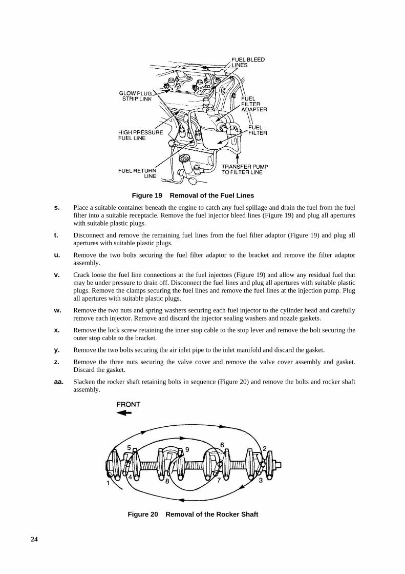
Figure 19 Removal of the Fuel Lines
s. Place a suitable container beneath the engine to catch any fuel spillage and drain the fuel from the fuelfilter into a suitable receptacle. Remove the fuel injector bleed lines (Figure 19) and plug all apertureswith suitable plastic plugs.
t. Disconnect and remove the remaining fuel lines from the fuel filter adaptor (Figure 19) and plug allapertures with suitable plastic plugs.
u. Remove the two bolts securing the fuel filter adaptor to the bracket and remove the filter adaptorassembly.
v. Crack loose the fuel line connections at the fuel injectors (Figure 19) and allow any residual fuel thatmay be under pressure to drain off. Disconnect the fuel lines and plug all apertures with suitable plasticplugs. Remove the clamps securing the fuel lines and remove the fuel lines at the injection pump. Plugall apertures with suitable plastic plugs.
w. Remove the two nuts and spring washers securing each fuel injector to the cylinder head and carefullyremove each injector. Remove and discard the injector sealing washers and nozzle gaskets.
x. Remove the lock screw retaining the inner stop cable to the stop lever and remove the bolt securing theouter stop cable to the bracket.
y. Remove the two bolts securing the air inlet pipe to the inlet manifold and discard the gasket.
z. Remove the three nuts securing the valve cover and remove the valve cover assembly and gasket.Discard the gasket.
aa. Slacken the rocker shaft retaining bolts in sequence (Figure 20) and remove the bolts and rocker shaft assembly.
Figure 20 Removal of the Rocker Shaft
24

bb. Remove the push rods and mark each rod to ensure correct location during installation.
The cylinder head is heavy, care must be taken on removal or personal injury may result.
cc. Loosen the cylinder head bolts in sequence (Figure 21). Remove the bolts and remove the cylinder head complete with inlet manifold, exhaust manifold and thermostat housing.
Figure 21 Removal of the Cylinder Head Bolts
dd. Remove the nuts and washers securing the inlet manifold to the cylinder head taking care not to lose the springs. Remove and discard the gasket.
ee. Remove the bolts, nuts and washers securing the heat shield and exhaust manifold to the cylinder head. Remove and discard the two gaskets.
ff. Remove the bolts securing the thermostat housing to the cylinder head. Remove and discard the gasket.
19. Cleaning and Inspection. Clean and inspect the cylinder head as follows:
a. Clean all trace of gasket material from the engine block, the cylinder head, the inlet and exhaustmanifolds and the thermostat housing.
b. Check the cylinder head for scratches, cracks, gouges and distortion. Using a straight edge and feelergauge, check that the cylinder head distortion is less than 0.20 mm (0.008 in) in several directions(Figure 22). Replace the cylinder head as necessary.
25

Figure 22 Checking for Cylinder Head Distortion
c. Check the fuel injector cavities for carbon build-up. If a light build-up is noticed, clean it with a wirebrush, however, if a heavy carbon build-up is evident, clean it with a suitable reamer.
d. Remove all trace of carbon build-up from the glow plug cavities and check all threads for cleanliness.
e. Using taps and dies, clean the threads in boltholes and on studs. Replace any damaged or bent studs.
f. Ensure that all oil and coolant galleries are free of restrictions.
g. Check that the push rods are not worn, damaged or bent. Replace them as necessary.
h. Check the rocker arms for contact surface wear and reface or replace as necessary. Check that all oilports and passages are free of restrictions.
i. Check the condition of all expansion plugs (Para 32) and replace them as necessary.
20. Installation. Install the cylinder head as follows:
a. Position the cylinder head so that the exhaust ports are uppermost.
b. Position two new exhaust manifold gaskets on the cylinder head so that the word TOP is toward themanifold (Figure 23).
Figure 23 Installation of the Exhaust Manifold Gasket
c. Place the exhaust manifold over the gaskets aligning the studs with the corresponding holes in themanifold. Secure the manifold in position with the four bolts and finger tighten the bolts. Check thateach gasket is correctly positioned and not distorted and install the four nuts and washers. Torque thenuts and bolts to 16 to 25 N.m (12 to 19 lbf.ft) using the tightening sequence in Figure 24. Position theheat shield on the exhaust manifold and secure it with the retaining nuts and washers.
26
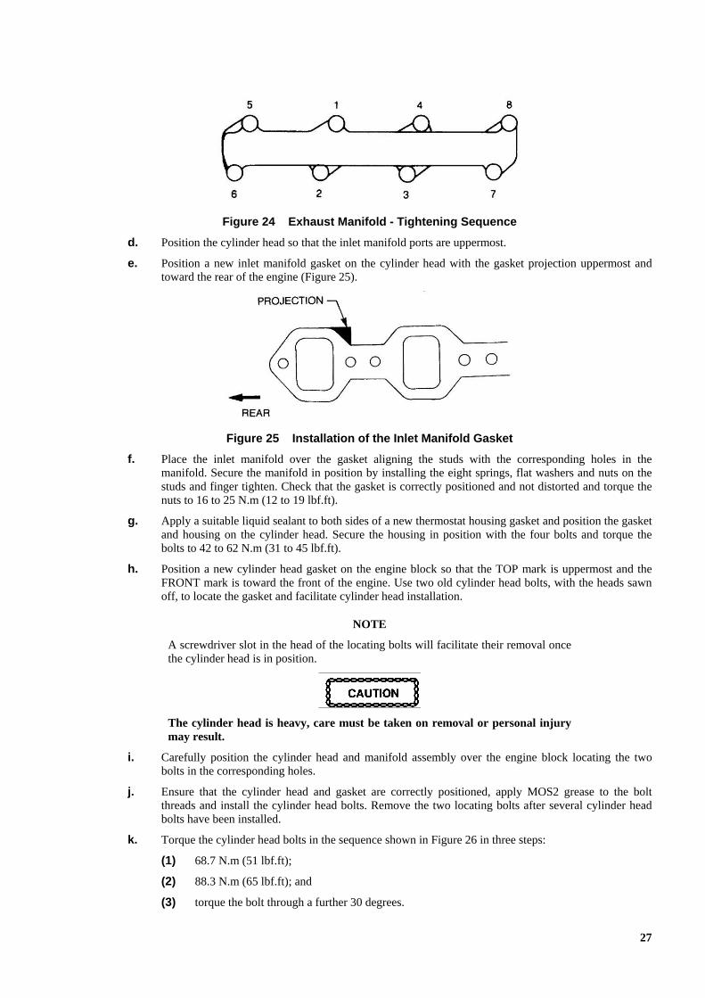
Figure 24 Exhaust Manifold - Tightening Sequence
d. Position the cylinder head so that the inlet manifold ports are uppermost.
e. Position a new inlet manifold gasket on the cylinder head with the gasket projection uppermost andtoward the rear of the engine (Figure 25).
Figure 25 Installation of the Inlet Manifold Gasket
f. Place the inlet manifold over the gasket aligning the studs with the corresponding holes in themanifold. Secure the manifold in position by installing the eight springs, flat washers and nuts on thestuds and finger tighten. Check that the gasket is correctly positioned and not distorted and torque thenuts to 16 to 25 N.m (12 to 19 lbf.ft).
g. Apply a suitable liquid sealant to both sides of a new thermostat housing gasket and position the gasketand housing on the cylinder head. Secure the housing in position with the four bolts and torque thebolts to 42 to 62 N.m (31 to 45 lbf.ft).
h. Position a new cylinder head gasket on the engine block so that the TOP mark is uppermost and theFRONT mark is toward the front of the engine. Use two old cylinder head bolts, with the heads sawnoff, to locate the gasket and facilitate cylinder head installation.
NOTE
A screwdriver slot in the head of the locating bolts will facilitate their removal once the cylinder head is in position.
The cylinder head is heavy, care must be taken on removal or personal injury may result.
i. Carefully position the cylinder head and manifold assembly over the engine block locating the twobolts in the corresponding holes.
j. Ensure that the cylinder head and gasket are correctly positioned, apply MOS2 grease to the boltthreads and install the cylinder head bolts. Remove the two locating bolts after several cylinder headbolts have been installed.
k. Torque the cylinder head bolts in the sequence shown in Figure 26 in three steps:
(1) 68.7 N.m (51 lbf.ft);
(2) 88.3 N.m (65 lbf.ft); and
(3) torque the bolt through a further 30 degrees.
27

Figure 26 Cylinder Head Bolts - Tightening Sequence
l. Lubricate the push rods with clean engine oil and install them in the cam followers as noted onremoval.
m. Position the rocker shaft assembly on the cylinder head and install the nuts, bolts and washers. Torquethem to 20 to 30 N.m (15 to 22 lbf.ft) in the sequence shown (Figure 27).
Figure 27 Rocker Shaft Assembly - Tightening Sequence
n. Adjust the valve clearance in accordance with Light Repair – Group 1.
o. Fit a new dust cap to each fuel injector and place a small amount of grease on each new nozzle gasket.Position a gasket over the nozzle on each injector.
NOTE
The grease will hold the nozzle gasket on the fuel injector during installation.
p. Install each injector in the cylinder head and secure them with the retaining nuts. Torque the nuts to 20to 30 N.m (15 to 22 lbf.ft).
q. Install the glow plugs and torque them to 22 to 27 N.m (16 to 20 lbf.ft). Position the electrical strip linkon the glow plugs and secure it with new nuts at cylinders 1, 2 and 3. Connect the electrical feed wireto cylinder number four glow plug and secure the feed wire and strip link to the glow plug with a newnut.
r. Lightly lubricate the rocker arm assembly with clean engine oil.
s. Fit a new gasket to the valve cover and position the valve cover on the engine. Secure the valve coverin position using a new washer and gasket on each retaining bolt. Torque the bolts to 16 to 26 N.m(12 to 19 lbf.ft).
t. Install the fuel lines between the injector pump and the fuel injectors and torque the bolts to28 to 31 N.m (21 to 23 lbf.ft). Install the fuel line clamp plates and tighten them securely (Figure 28).
28
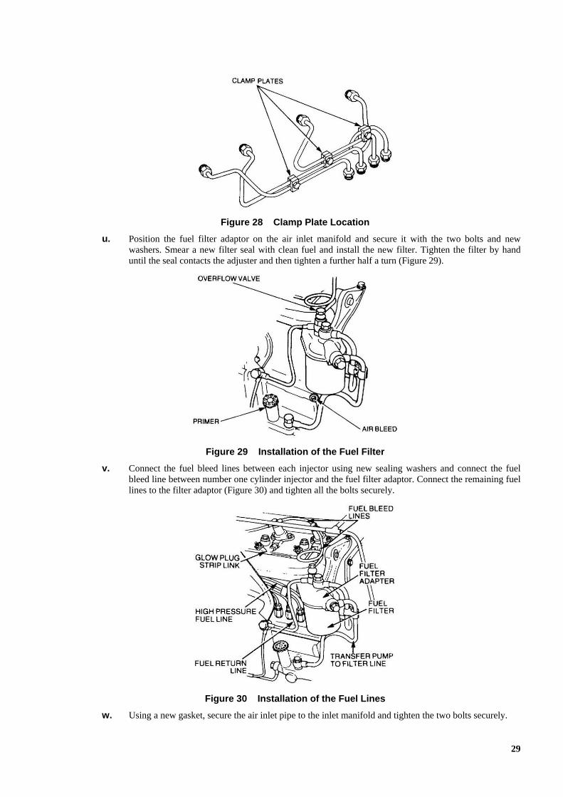
Figure 28 Clamp Plate Location
u. Position the fuel filter adaptor on the air inlet manifold and secure it with the two bolts and newwashers. Smear a new filter seal with clean fuel and install the new filter. Tighten the filter by handuntil the seal contacts the adjuster and then tighten a further half a turn (Figure 29).
Figure 29 Installation of the Fuel Filter
v. Connect the fuel bleed lines between each injector using new sealing washers and connect the fuelbleed line between number one cylinder injector and the fuel filter adaptor. Connect the remaining fuellines to the filter adaptor (Figure 30) and tighten all the bolts securely.
Figure 30 Installation of the Fuel Lines
w. Using a new gasket, secure the air inlet pipe to the inlet manifold and tighten the two bolts securely.
29

x. Position the engine stop inner cable to the stop lever and the outer cable to the bracket, tighten thelocking screw and the retaining bolt securely.
y. Connect the electrical connector to the temperature sensor.
z. Install the coolant by-pass between the thermostat housing and the water pump.
aa. Position the heater hose and vacuum line assembly on the engine. Insert the two retaining bolts through the mounting brackets and tighten the bolts securely. Connect the vacuum line to the brake servo and to the vacuum pump on the rear of the alternator and then install the rear engine lifting bracket. Tighten all bolts securely. Connect the heater hoses to the thermostat housing, the water pump and the heater inlet and outlet pipes (Figure 31) and tighten the hose clamps securely.
Figure 31 Installation of the Heater Hoses and Vacuum Line
bb. Connect the turbocharger coolant hose to the thermostat housing and install the bolt securing the coolant pipe to the exhaust manifold. Tighten the clamp and the bolt securely.
cc. Install the dipstick top-supporting bracket retaining bolt and tighten it securely.
dd. Secure the alternator adjustment bracket to the water pump with the retaining bolt. Adjust the alternator to give a 10 to 15 mm deflection of the fanbelt and tighten the alternator mounting and adjusting bolts securely.
ee. Position the air cleaner bracket at the rear of the engine and install the two retaining bolts, tighten the bolts securely.
ff. Carefully position the air cleaner in the mounting bracket and tighten the two wing-nuts on the clamp bolts. Connect the air inlet and outlet hoses and tighten the hose clamps securely.
gg. Connect the breather hose between the valve cover and the air inlet tube.
hh. Install the turbocharger in accordance with Light Repair – Group 4.
ii. Using a new sealing ring secure the front exhaust pipe to the turbocharger exhaust adaptor ensuringthat the sealing ring is correctly seated in the flange. Tighten the exhaust flange nuts and the mountingclamp nuts securely.
jj. Install the top radiator hose and tighten the clamps securely.
kk. Fill the cooling system in accordance with Light Repair – Group 2. ll.
Bleed the fuel system in accordance with Light Repair – Group 4. mm. Install
the bonnet (Body – Group 17).
nn. Start the engine and allow it to warm up to normal operating temperature. Check for oil, fuel or coolant leaks and rectify them as necessary. Ensure that the engine functions correctly and rectify any faults found.
oo. Bleed the power steering system in accordance with Light Repair – Group 14.
30

Camshaft Followers
21. Removal. Remove the camshaft followers as follows:
a. Clean the engine and engine bay with a recommended cleaning agent paying particular attention to thearea around the valve cover, timing cover and side covers. Blow it dry with compressed air.
b. Drain the engine oil into a suitable receptacle and reinstall the drain plug together with a new sealingring and tighten it securely.
c. Disconnect the battery.
d. Remove the bonnet (Body – Group 17).
e. Remove the bumper brush guard in accordance with Light Repair – Group 16.
f. Remove the grille in accordance with Light Repair – Group 17.
g. Remove the connector from the spade terminal on the horn.
h. Remove the two bolts and washers securing the top of the cross-braces to the grille top panel. Removethe bolts, washers and nuts securing the bottom of the cross-braces to the chassis and remove the cross-braces.
i. Remove the six bolts and washers securing the grille panel to the mudguards and lift the grille paneland the grille top panel from the vehicle.
j. Remove the radiator in accordance with Light Repair – Group 2.
k. Slacken the alternator mounting bolts (Figure 32), remove the adjusting bolt and remove the fanbelt.
l. Remove the screws securing the fan shroud to gain access to the fan retaining bolts.
m. Remove the bolts and washers retaining the cooling fan to the water pump drive flange and remove thefan, spacer and drive pulley.
n. Disconnect the hoses from the power steering pump and plug the hoses and power steering pumpadaptors.
o. Remove the nut and washer securing the crankshaft pulley to the crankshaft, install special tool8521-0063-0 and remove the pulley.
p. Remove the bolts securing the timing cover to the timing case and remove the cover. Remove anddiscard the oil seal.
q. Remove the three nuts securing the valve cover and remove the valve cover assembly and gasket.Discard the gasket.
Figure 32 Alternator Adjusting Bolts
31

r. Slacken the rocker shaft retaining bolts and nuts in sequence (Figure 33) and remove the bolts, nutsand rocker shaft assembly.
Figure 33 Removal of the Rocker Shaft
s. Remove the push rods and mark each rod to ensure correct location during installation.
t. Remove the nuts and bolts securing the oil pan to the engine block then remove the oil pan, thesupporting plates and the gaskets. Discard the gaskets.
u. Remove the oil pump cover from the left-hand side of the engine block and using an Allen key,remove the grub screw locating the oil pump drive pinion thrust bearing and remove the thrust bearingtogether with the drive pinion.
v. Remove the bolts securing the side covers to the engine block and remove the side covers. Discard thegaskets and the bolt sealing washers.
w. Lift the camshaft followers from the camshaft lobes and support the followers in the raised positionwith suitable clips or tape, ensuring that there is sufficient clearance to remove the camshaft.
x. Rotate the camshaft drive gear to align the holes in the gear with the thrust plate retaining bolts.Remove the retaining bolts and carefully withdraw the camshaft from the engine block, ensuring thatthe camshaft lobes do not scratch or damage the camshaft bearings.
y. Match mark or number the camshaft followers, (to ensure correct location at installation), then removethe device supporting the followers and remove the followers.
NOTE
The camshaft followers will drop from the engine when the support is removed.
22. Cleaning and Inspection. Clean and inspect the camshaft followers as follows:
a. Clean the camshaft followers with a suitable cleaning agent using steel wool or a wire brush to removeany carbon build-up.
b. Inspect the camshaft followers for cracks, pitting or irregular wear (Figure 34).
Figure 34 Camshaft Follower Wear Patterns
c. Clean all trace of gasket material from the engine block and timing cover.
32
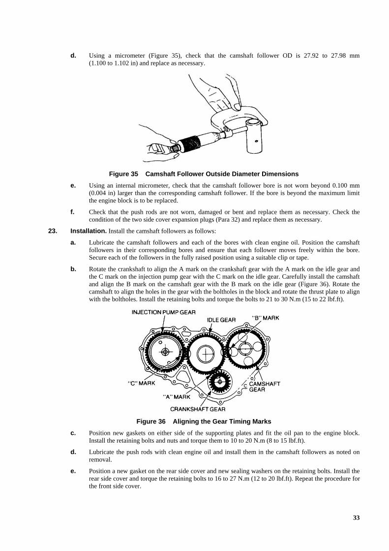
d. Using a micrometer (Figure 35), check that the camshaft follower OD is 27.92 to 27.98 mm(1.100 to 1.102 in) and replace as necessary.
Figure 35 Camshaft Follower Outside Diameter Dimensions
e. Using an internal micrometer, check that the camshaft follower bore is not worn beyond 0.100 mm(0.004 in) larger than the corresponding camshaft follower. If the bore is beyond the maximum limitthe engine block is to be replaced.
f. Check that the push rods are not worn, damaged or bent and replace them as necessary. Check thecondition of the two side cover expansion plugs (Para 32) and replace them as necessary.
23. Installation. Install the camshaft followers as follows:
a. Lubricate the camshaft followers and each of the bores with clean engine oil. Position the camshaftfollowers in their corresponding bores and ensure that each follower moves freely within the bore.Secure each of the followers in the fully raised position using a suitable clip or tape.
b. Rotate the crankshaft to align the A mark on the crankshaft gear with the A mark on the idle gear andthe C mark on the injection pump gear with the C mark on the idle gear. Carefully install the camshaftand align the B mark on the camshaft gear with the B mark on the idle gear (Figure 36). Rotate thecamshaft to align the holes in the gear with the boltholes in the block and rotate the thrust plate to alignwith the boltholes. Install the retaining bolts and torque the bolts to 21 to 30 N.m (15 to 22 lbf.ft).
Figure 36 Aligning the Gear Timing Marks
c. Position new gaskets on either side of the supporting plates and fit the oil pan to the engine block.Install the retaining bolts and nuts and torque them to 10 to 20 N.m (8 to 15 lbf.ft).
d. Lubricate the push rods with clean engine oil and install them in the camshaft followers as noted onremoval.
e. Position a new gasket on the rear side cover and new sealing washers on the retaining bolts. Install therear side cover and torque the retaining bolts to 16 to 27 N.m (12 to 20 lbf.ft). Repeat the procedure forthe front side cover.
33

f. Position the rocker shaft assembly on the cylinder head and install the retaining bolts, washers andnuts. Torque the bolts and nuts to 20 to 30 N.m (15 to 22 lbf.ft) in sequence (Figure 27).
g. Adjust the valve clearance in accordance with Light Repair – Group 1.
h. Fit a new gasket to the valve cover and position the valve cover on the engine. Secure the valve coverin position using a new washer and gasket on each retaining bolt. Torque the bolts to 16 to 26 N.m(12 to 19 lbf.ft).
i. Connect the breather hose between the valve cover and the air inlet tube.
j. Install a new seal into the timing cover ensuring that the open side of the seal is facing towards the rearof the cover. Smear the timing cover oil seal lip with rubber grease and position a new gasket on thetiming cover using the timing cover retaining bolts to hold the gasket in place. Install the timing coverensuring that the gasket is correctly aligned and the sealing lip on the seal is not distorted. Install theretaining bolts and torque them to 21 to 30 N.m (15 to 22 lbf.ft).
k. Install the two Woodruff keys onto the crankshaft and the dust thrower onto the back of the crankshaftpulley. Smear the seal rubbing surface on the crankshaft pulley with rubber grease. Position the pulleyover the end of the crankshaft, align the keyway with the keys and push the pulley onto the crankshaft.Install the retaining nut and washer and torque them to 382 to 480 N.m (282 to 354 lbf.ft).
l. Connect the hoses to the power steering pump adaptors.
m. Position the drive pulley, spacer and cooling fan on the water pump drive flange. Align the boltholesand install and securely tighten the four retaining bolts. Position the fanbelt over the pulleys and adjustthe tension of the fan belt by moving the alternator outward. Check for a belt deflection of 10 to 15mm between the water pump and alternator pulleys. When the correct tension is obtained, securelytighten the alternator adjusting bolt and the alternator mounting bolts.
n. Install the radiator in accordance with Light Repair – Group 2.
o. Install the grille and top panel and secure them to the mudguards using the six bolts and washers.
p. Install the cross-braces and secure them to the chassis and grille top panel with the bolts, washers andnuts.
q. Install the oil pump drive pinion and thrust bearings, insert and tighten the grub screw to locate thethrust bearing. Install the oil pump cover and a new gasket, tighten the bolts securely.
r. Connect the wiring harness to the horn and install the front grille. Fit the eight screws and tighten themsecurely.
s. Install the bumper brush guard in accordance with Light Repair – Group 16.
t. Install the bonnet (Body – Group 17).
u. Connect the battery.
v. Replenish the engine with approximately 8.5 litres of new engine oil. Start the engine and allow it towarm up to normal operating temperature. Check for oil leaks and rectify them as necessary. Ensurethat the engine functions correctly and rectify any faults found. Check the oil level and top up ifrequired.
Oil Pump
24. Removal. Remove the oil pump as follows:
a. Clean the oil pan and surrounding area with a recommended cleaning agent and blow them dry withcompressed air.
b. Position a suitable receptacle beneath the engine, remove the drain plug from the oil pan (sump) anddrain the engine oil. Install the drain plug and tighten it securely.
c. Remove the bolts and nuts securing the oil pan to the engine block and remove the oil pan.
d. Wipe the oil pump with a clean dry cloth and remove the two bolts and washers securing the oil pipe tothe engine block.
e. Remove the two bolts securing the oil pump to the engine block and remove the oil pump and strainerassembly.
34

25. Disassembly. Disassemble the oil pump as follows:
a. Remove the wire clip retaining the strainer gauze to the strainer body. Remove the four bolts securingthe strainer body and the oil pump cover to the oil pump body (Figure 37).
Figure 37 Oil Pump - Exploded View
b. Remove the short oil pipe and spacer from the oil pump cover.
c. Remove the collar and the drive gear from the drive coupling. Slide the coupling off the oil pump driveshaft (Figure 38).
Figure 38 Removal of the Drive Pinion, Collar and Coupling
d. Withdraw the drive shaft from the oil pump body and remove the driven gear from the locating pin inthe cover.
e. Remove the split pin, relief valve ball, seat and spring from the bore in the oil pump cover (Figure 39).Discard the split pin.
35
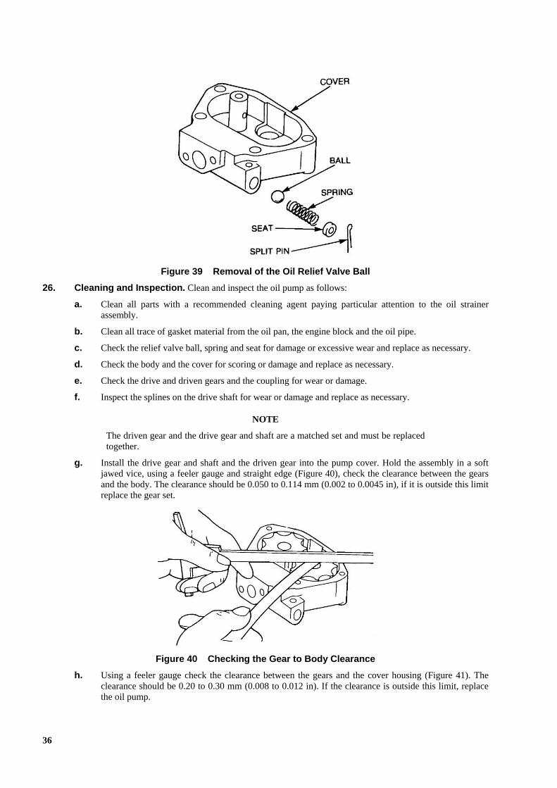
Figure 39 Removal of the Oil Relief Valve Ball
26. Cleaning and Inspection. Clean and inspect the oil pump as follows:
a. Clean all parts with a recommended cleaning agent paying particular attention to the oil strainerassembly.
b. Clean all trace of gasket material from the oil pan, the engine block and the oil pipe.
c. Check the relief valve ball, spring and seat for damage or excessive wear and replace as necessary.
d. Check the body and the cover for scoring or damage and replace as necessary.
e. Check the drive and driven gears and the coupling for wear or damage.
f. Inspect the splines on the drive shaft for wear or damage and replace as necessary.
NOTE
The driven gear and the drive gear and shaft are a matched set and must be replaced together.
g. Install the drive gear and shaft and the driven gear into the pump cover. Hold the assembly in a softjawed vice, using a feeler gauge and straight edge (Figure 40), check the clearance between the gearsand the body. The clearance should be 0.050 to 0.114 mm (0.002 to 0.0045 in), if it is outside this limitreplace the gear set.
Figure 40 Checking the Gear to Body Clearance
h. Using a feeler gauge check the clearance between the gears and the cover housing (Figure 41). Theclearance should be 0.20 to 0.30 mm (0.008 to 0.012 in). If the clearance is outside this limit, replacethe oil pump.
36

Figure 41 Checking the Gear to Cover Clearance
i. Remove the drive and the driven gears from the housing cover.
27. Reassembly. Reassemble the oil pump as follows:
a. Lubricate the driven and drive gears, the drive shaft and the oil pump cover with clean engine oil.
b. Install the driven gear and the drive gear and shaft in the pump cover.
c. Locate the spacer and the short oil pipe in the pump cover and install the four bolts securing thestrainer body and pump cover to the pump body.
d. Install the strainer gauze to the strainer body with the wire clip.
e. Lubricate the relief valve ball, spring and seat with clean engine oil and install them in the bore of theoil pump cover. Retain the items with a new split pin.
f. Slide the drive coupling over the drive shaft splines and install the drive pinion into the splines of thedrive coupling. Position the collar on top of the drive gear.
g. Invert the oil pump and pour clean engine oil through the strainer, turn the drive shaft a few times toprime the oil pump.
28. Installation. Install the oil pump as follows:
a. Position the oil pump on the engine block engaging the drive shaft with the driven gear. When the oilpump is correctly positioned, install the two retaining bolts and finger tighten only.
b. Position a new gasket between the oil pipe and the engine block and secure the oil pipe with the tworetaining bolts. Ensure that the gasket does not distort as the bolts are tightened.
c. Torque the oil pump to cylinder block retaining bolts to 42 to 60 N.m (31 to 45 lbf.ft).
d. Position a new gasket on the engine block and place the oil pan over the gasket. Place a new gasketand the supporting plates over the rim of the oil pan and install the retaining bolts and washers. Torquethe retaining bolts to 10 to 20 N.m (8 to 15 lbf.ft).
e. Fill the engine with clean engine oil checking the oil level with the dipstick.
f. Start the engine and allow it to warm up to normal operating temperature. Check for oil leaks andrectify as necessary.
37
Oil Cooler
29. Removal. Remove the oil cooler as follows:
a. Clean the engine with a recommended cleaning agent paying particular attention to the area around thefuel injection pump and the oil cooler. Blow the area dry with compressed air.
b. Place a suitable receptacle beneath the radiator, loosen the bottom radiator hose and drain the coolantinto the receptacle. Reinstall the hose and tighten the clamp securely.
c. Remove the oil filters using an oil filter removing tool.
d. Remove the fuel injection pump and fuel filter in accordance with Light Repair – Group 4.
e. Remove the bolts securing the oil pipe to the oil cooler and the oil filter adaptor. Discard the sealingrings.
NOTE
The oil cooler retaining bolts are different sizes. Accordingly, note the position of each bolt on removal to ensure correct positioning on installation.
f. Remove the bolts securing the oil cooler to the engine block and remove the oil cooler. Discard thegasket.
g. Remove the bolts securing the oil cooler element to the housing and remove the element from thehousing. Discard the two gaskets.
h. Remove the check valve retaining bolt, the spring and valve assembly. Discard the washer from theretaining bolt.
30. Cleaning and Inspection. Clean and inspect the oil cooler as follows:
a. Clean all components with a recommended cleaning agent and blow them dry with compressed air.
b. Remove all trace of gasket material from the oil cooler housing and the engine block.
c. Inspect the check valve spring for wear, damage or loss of tension and replace as necessary.
d. Remove any scale build-up with a wire brush. If scale cannot be removed soak the affectedcomponents in a recommended solvent and carefully blow them dry with compressed air. If scalecannot be removed with a wire brush after soaking, replace parts as necessary.
e. Check the housing and element for cracks or pitting and replace as necessary.
31. Installation. Install the oil cooler as follows:
a. Position two new gaskets on the element studs and install the element in the oil cooler housing. Torquethe retaining nuts to 20 to 30 N.m (15 to 22 lbf.ft).
b. Invert the oil cooler and insert the check valve and spring. Position a new washer on the retaining boltand tighten it securely.
38

c. Install a new gasket on the oil cooler housing and hold the gasket in position with retaining bolts ateach end. Position the oil cooler on the engine block and secure it with the retaining bolts in thepositions noted on removal. Torque the bolts to 20 to 30 N.m (15 to 22 lbf.ft) in sequence (Figure 42).
Figure 42 Oil Cooler - Tightening Sequence
d. Fit new sealing rings and install the oil pipe between the oil cooler and the oil filter adaptor. Tightenthe retaining bolts securely.
e. Install the fuel injector pump and fuel filter in accordance with Light Repair – Group 4.
f. Apply a film of clean engine oil to the oil filter seal and carefully install the oil filter avoidingcross-threading. Tighten the filter a further half a turn after the seal contacts the adaptor.
g. Fill the engine with approximately 8.5 litres of new engine oil. Check the level on the dipstick andtop up as necessary.
h. Fill the cooling system in accordance with Light Repair – Group 2.
Expansion Plugs
32. Removal. Remove the expansion plugs as follows:
NOTE
Figures 43 and 44 illustrate the location of expansion plugs on the engine assembly. Removal of some engine components will facilitate access to the expansion plug to be removed. Refer to the relevant Group in Light Repair or this repair manual for the appropriate component removal and installation procedures.
a. Drain the engine oil or cooling system as necessary.
39

Figure 43 Engine Expansion Plug Location
Figure 44 Cylinder Head Expansion Plug Location
b. Using a sharp instrument pierce a hole in the expansion plug and prise the plug out. Discard the plug.
NOTE
The small expansion plugs may be difficult to remove. If necessary, use a drill but do not exceed the outer diameter of the expansion plug.
33. Installation. Install the expansion plugs as follows:
a. Ensure that the plug cavity is clean and apply a suitable sealant to the expansion plug.
b. Place the plug in the cavity and tap it into position ensuring that the plug is even and flush with thesurround.
c. Install any engine components previously removed and replenish the engine oil and/or cooling systemas necessary.
40
Flywheel and Ring-gear
34. Removal. Remove the flywheel and ring-gear as follows:
a. Remove the transmission (Transmission – Group 6).
b. Remove the clutch assembly (Clutch – Group 5).
c. Lock the flywheel to prevent it from rotating and suitably support the flywheel. Remove the sixretaining bolts and remove the flywheel.
d. Partially cut through the ring-gear with a hacksaw and knock the ring-gear from the flywheel using ahammer and cold chisel.
35. Installation. Install the flywheel and ring-gear as follows:
a. Fit a new ring-gear by heating it uniformly and positioning the ring-gear on the flywheel. Ensure thatthe ring-gear is positioned evenly against the shoulder on the flywheel and allow it to cool.
b. Lubricate the retaining bolts with clean engine oil.
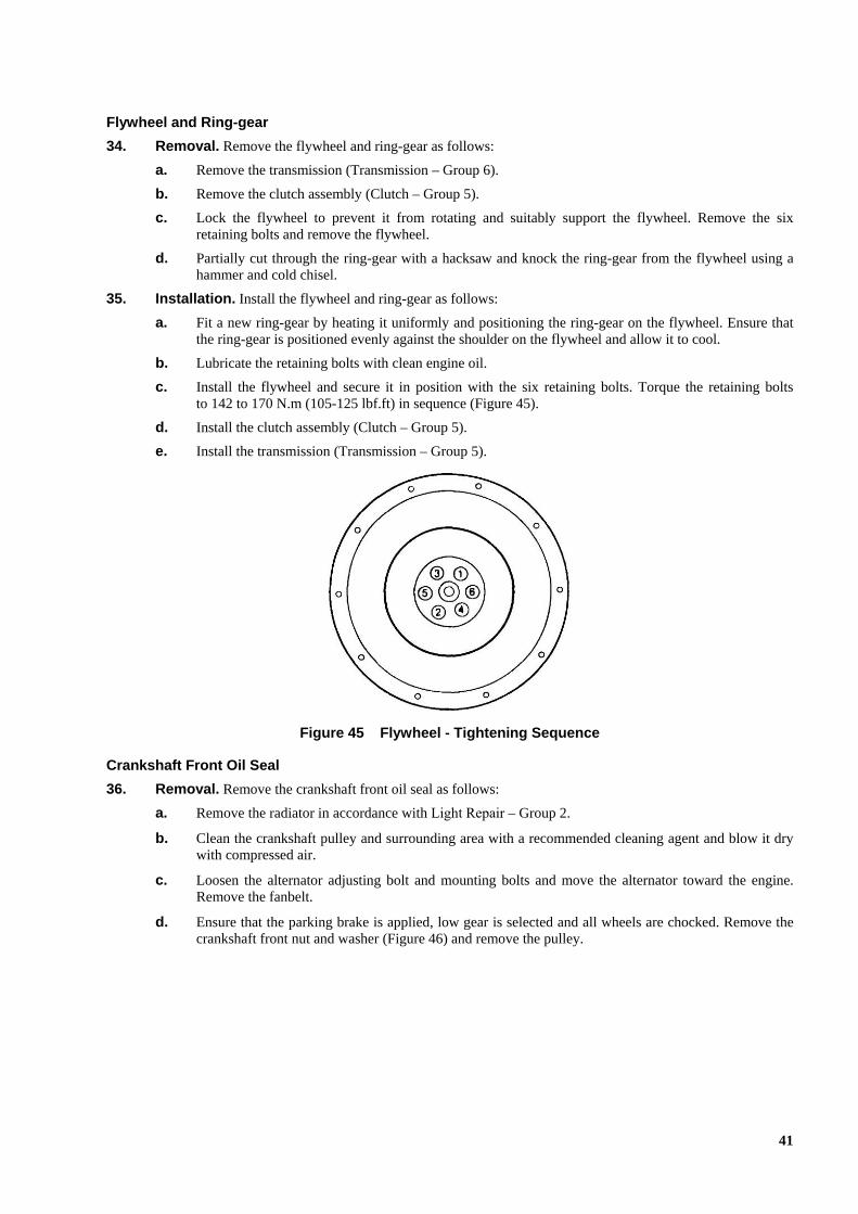
c. Install the flywheel and secure it in position with the six retaining bolts. Torque the retaining boltsto 142 to 170 N.m (105-125 lbf.ft) in sequence (Figure 45).
d. Install the clutch assembly (Clutch – Group 5).
e. Install the transmission (Transmission – Group 5).
Figure 45 Flywheel - Tightening Sequence
Crankshaft Front Oil Seal
36. Removal. Remove the crankshaft front oil seal as follows:
a. Remove the radiator in accordance with Light Repair – Group 2.
b. Clean the crankshaft pulley and surrounding area with a recommended cleaning agent and blow it drywith compressed air.
c. Loosen the alternator adjusting bolt and mounting bolts and move the alternator toward the engine.Remove the fanbelt.
d. Ensure that the parking brake is applied, low gear is selected and all wheels are chocked. Remove thecrankshaft front nut and washer (Figure 46) and remove the pulley.
41

Figure 46 Removal of the Crankshaft Pulley
e. Remove the oil seal using a lever or seal puller as required.
37. Installation. Install the crankshaft front oil seal as follows:
a. Lubricate the outer surface of a new seal with clean engine oil and position the seal on the timing casecover. Install the seal using special tool 18GA092 (Figure 47).
Figure 47 Installation of the Crankshaft Front Oil Seal
b. Ensure that the seal rubbing surface on the pulley is not grooved or worn and install the pulley, washerand nut. Torque the nut to 382 to 480 N.m (282 to 354 lbf.ft).
c. Install the fanbelt and adjust the alternator for a 10 to 15 mm deflection on the longest span of thefanbelt when depressed with the thumb.
d. Install the radiator in accordance with Light Repair – Group 2.
Crankshaft Rear Oil Seal
38. Removal. Remove the crankshaft rear oil seal as follows:
a. Remove the flywheel (Para 41).
b. Pry off or pull out the oil seal from the flywheel housing and discard it.
39. Cleaning and Inspection. Clean and inspect the crankshaft rear oil seal as follows:
a. Remove all trace of gasket material from the engine block and the flywheel housing.
b. Clean the flywheel housing with a recommended cleaning agent and blow it dry with compressed air.
c. Clean and inspect the crankshaft oil seal journal for any abrasion or scoring which may have beencaused by previous oil seals.
42

Emery dust or metal filings must not be allowed to enter the engine and must be completely removed before continuing.
d. Carefully remove any burrs or rough areas with emery paper or a fine file. Thoroughly clean away anyresulting filings or emery paper dust. If wear is greater than 0.1 mm deep or wide, fill the damagedarea with Loctite 3805 to prevent oil seeping under the seal.
e. Inspect the seal installation, crank plate and push cone and carefully remove any burrs or sharp edges,particularly those on the outer diameter of the crank plate.
Handle the crank plate and push cone carefully during use to avoid causing burrs or sharp edges that may damage the seal during installation and cause early failure.
40. Installation. Install the crankshaft rear oil seal as follows:
a. Fit the crank plate to the crankshaft with one hole positioned at the dowel pin and the other three holesaligned with the flywheel bolt holes (Figure 48). Secure the crank plate with the short screws, ensuringthe screws are evenly tightened.
Figure 48 Crank Plate (Secured to Crankshaft)
NOTE
Before installation, apply only clean engine oil to the outside surface of the new type of seal. Do not apply any type of sealant in an attempt to improve the sealing between the housing and the outer surface of the new seal.
b. Lubricate the outside surface of the new seal with clean engine oil. Position the seal over the crankguide so that the part number stamped on the flange of the green inner sleeve is visible. Push the seal,by hand, along the crank guide until it contacts the crankshaft (Figure 49).
43

Figure 49 New Type of Seal (Placed on Crank Plate Ready for Installation)
c. Position the push cone over the crank guide, locate it onto the seal and then engage the long screw intothe crank guide (Figure 50).
Figure 50 Push Cone (Located on Crank Plate and Against Seal)
To minimise creep back of the seal rubber and to ensure the seal remains in the correct position during service, the push cone must be left tight against the seal for at least two minutes.
d. Rotate the screw to push the seal into its housing until hard resistance is felt. Leave the push cone inplace for at least two minutes before loosening the screw.
NOTE
The presence of green bore sealant after the seal has been installed does not indicate there is a fault with the newly installed seal. However, if it does appear, it should be cleaned away using workshop wiping cloths.
44

e. Remove the push cone and crank guide and clean away any green bore sealant that may have beenforced from inside the seal.
f. Clean away any excess engine oil from the general area.
g. Install the flywheel (Para 41).
NOTE
Prior to installing the clutch assembly, check for wear or damage on the clutch plate and pressure plate, and check the release bearing for smoothness of operation.
h. Install the clutch assembly (Clutch – Group 5).
i. Install the transmission (Transmission – Group 6).
Special Tools for Crankshaft Rear Oil Seal
The special tools required for the installation of the crankshaft rear oil seal are listed in Table 5
Table 5 Special Tools Required For Crankshaft Rear Oil Seal Installation
Item NSN Mfr Part No Designation or Description Unit of Issue Qty
1 2815-66-149-1913 EYA3737 Tool kit, seal installation (includes items 2 to 6) ea NA
2 NA EYA3738 Crank plate, seal install tool ea 1
3 NA EYA3739 Push cone, seal install tool ea 1
4 NA NA Screw, socket head cap, 14 x 1.5, 35 mm long ea 3
5 NA NA Screw, socket head cap, 14 x 2, 50 mm long ea 1
6 NA EYA3740 Case, carry ea 1
45

Engine Specifications
41. The engine specifications are detailed in Table 6.
Table 6 Engine Specifications
Serial Item Specification
1 Clutch slave cylinder tightening torque 27 N.m (20 lbf.ft)
2 Tightening torque (pipe bracket) 40 N.m (30 lbf.ft)
3 Cylinder head distortion Less than 0.20 mm (0,008 in)
4 Cylinder head tightening torque - first step 68.7 N.m (51 lbf.ft)
5 Second step 88.3 N.m (65 lbf.ft)
6 Final step + 30 degrees
7 Exhaust manifold tightening torque 16 to 5 N.m (12 to 19 lbf.ft)
8 Air inlet manifold tightening torque 16 to 25 N.m (12 to 19 lbf.ft)
9 Thermostat housing tightening torque 42 to 62 N.m (31 to 45 lbf.ft)
10 Rocker shaft tightening torque 20 to 30 N.m (15 to 22 lbf.ft)
11 Fuel injectors tightening torque 20 to 30 N.m (15 to 22 lbf.ft)
12 Glow plugs tightening torque 22 to 27 N.m (16 to 20 lbf.ft)
13 Valve cover tightening torque 16 to 26 N.m (12 to 19 lbf.ft)
14 Fuel lines – high pressure tightening torque 28 to 31 N.m (21 to 23 lbf.ft)
15 Turbocharger to exhaust manifold tightening torque 30 to 34 N.m (22 to 25 lbf.ft)
16 Fanbelt deflection 10 to 15 mm
17 Cam followers - nominal O D 27.92 to 27.98 mm (1.100 to 1.102 in)
18 Cam follower-to-bore clearance - maximum 0.100 mm (0.004 in)
19 Engine side covers tightening torque 16 to 27 N.m (12 to 20 lbf.ft)
20 Engine breather tightening torque 16 to 25 N.m (12 to 19 lbf.ft)
21 Oil pump - gear to body clearance 0.050 to 0.114 mm (0.002 to 0.0045 in)
22 Gear to cover clearance 0.20 to 0.30 mm (0.008 to 0.012 in)
23 Drive shaft to pump housing clearance 0.032 to 0.070 mm (0.0013 to 0.0028 in)
24 Oil pump tightening torque 42 to 60 N.m (31 to 45 lbf.ft)
25 Engine oil pan (sump) tightening torque 10 to 20 N.m (8 to 15 lbf.ft)
26 Oil cooler tightening torque (element to cooler) 20 to 30 N.m (15 to 22 lbf.ft)
27 Oil cooler tightening torque 20 to 30 N.m (15 to 22 lbf.ft)
28 Flywheel tightening torque 142 to 170 N.m (105 to 125 lbf.ft)
29 Crankshaft front nut tightening torque 382 to 480 N.m (282 to 354 lbf.ft)
30 Crankshaft rear oil seal retainer tightening torque 20 to 30 N.m (15 to 22 lbf.ft)
46

Engine Fault Finding
42. The engine fault finding is detailed in Table 7.
Table 7 Engine Fault Finding
Serial Symptom Probable Cause Action
Defective fuel injectors Replace defective injectors
Incorrectly adjusted valves Adjust the valves to the correct clearances
1 Engine misfiring
Worn or broken piston rings Replace the engine
Air leaks in the fuel supply Trace the leak then rectify
Internal or external fuel leaks Rectify
Incorrectly adjusted throttle linkage Adjust the linkages to the correct specifications
Governor weights incorrectly adjusted Replace fuel injection pump
Water in fuel Drain sedimenters Drain and flush the fuel tanks Replace the fuel filter then fill the fuel tanks with clean fuel
Incorrect fuel pump calibration Replace pump
Cylinder head gasket blow-by or leakage Replace cylinder head gasket
2 Engine stalls at low speed
Blocked in-line filter Clean or replace filter
Governor weights assembled incorrectly Replace fuel injection pump 3 Erratic engine speed
Incorrectly calibrated fuel injection pump Replace fuel injection pump
Incorrectly calibrated fuel injection pump Replace fuel injection pump 4 Low power
Defective fuel injector(s) Replace defective injectors
Water in the fuel Drain sedimenters. Drain and flush the fuel tanks. Replace the fuel filter then fill the tank with clean fuel
Incorrectly calibrated fuel injection pump Replace fuel injection pump
Defective fuel injector(s) Replace defective injectors
5 Engine will not reach no-load governed speed
Blocked in-line filter Clean or replace filter
Defective fuel injector(s) Replace defective injectors
Incorrect fuel pump calibration Replace fuel injection pump
Clogged air cleaner elements Replace air cleaner elements
Oil level too high resulting in viscous drag on crankshaft
Adjust oil level
6 Excessive fuel consumption
Overloaded engine Ensure correct driving techniques
Blocked coolant passages Flush system
Incorrectly calibrated fuel injection Replace fuel injection pump
Exterior of the engine caked with dirt Clean engine and grime
Blocked radiator Clean
Broken or loose fanbelt Replace or adjust
Low coolant level Fill
Faulty thermostat Replace thermostat
7 Engine overheats
Faulty expansion tank cap Replace expansion tank cap
47