Embed Size (px)
Citation preview

Courtesy
EIO0000000067 10/2010
EIO
0000
0000
67.0
4
www.schneider-electric.com
SoMachineProgramming Guide
10/2010
of Steven Engineering, Inc.-230 Ryan Way, South San Francisco, CA 94080-6370-Main Office: (650) 588-9200-Outside Local Area: (800) 258-9200-www.stevenengineering.com
Courtesy of St
The information provided in this documentation contains general descriptions and/or technical characteristics of the performance of the products contained herein. This documentation is not intended as a substitute for and is not to be used for determining suitability or reliability of these products for specific user applications. It is the duty of any such user or integrator to perform the appropriate and complete risk analysis, evaluation and testing of the products with respect to the relevant specific application or use thereof. Neither Schneider Electric nor any of its affiliates or subsidiaries shall be responsible or liable for misuse of the information contained herein. If you have any suggestions for improvements or amendments or have found errors in this publication, please notify us.
No part of this document may be reproduced in any form or by any means, electronic or mechanical, including photocopying, without express written permission of Schneider Electric.
All pertinent state, regional, and local safety regulations must be observed when installing and using this product. For reasons of safety and to help ensure compliance with documented system data, only the manufacturer should perform repairs to components.
When devices are used for applications with technical safety requirements, the relevant instructions must be followed.
Failure to use Schneider Electric software or approved software with our hardware products may result in injury, harm, or improper operating results.
Failure to observe this information can result in injury or equipment damage.
© 2010 Schneider Electric. All rights reserved.
2 EIO0000000067 10/2010
even Engineering, Inc.-230 Ryan Way, South San Francisco, CA 94080-6370-Main Office: (650) 588-9200-Outside Local Area: (800) 258-9200-www.stevenengineering.com
Courtesy o
Table of Contents
Safety Information . . . . . . . . . . . . . . . . . . . . . . . . . . . . . . 7About the Book . . . . . . . . . . . . . . . . . . . . . . . . . . . . . . . . . 9
Part I Introduction . . . . . . . . . . . . . . . . . . . . . . . . . . . . . . . . 13Chapter 1 Introduction about Programming . . . . . . . . . . . . . . . . . . 15
Programming. . . . . . . . . . . . . . . . . . . . . . . . . . . . . . . . . . . . . . . . . . . . . . . 15Chapter 2 Managing Projects with SoMachine 2.0 . . . . . . . . . . . . . 17
Main Tasks . . . . . . . . . . . . . . . . . . . . . . . . . . . . . . . . . . . . . . . . . . . . . . . . 17
Part II Manage Your Project . . . . . . . . . . . . . . . . . . . . . . . . . 19Chapter 3 Home . . . . . . . . . . . . . . . . . . . . . . . . . . . . . . . . . . . . . . . . . 21
3.1 General Information. . . . . . . . . . . . . . . . . . . . . . . . . . . . . . . . . . . . . . . . . . 22General Description of the Main Selection Screen . . . . . . . . . . . . . . . . . . 23Accessing General Functions . . . . . . . . . . . . . . . . . . . . . . . . . . . . . . . . . . 25
3.2 Show Existing Machine . . . . . . . . . . . . . . . . . . . . . . . . . . . . . . . . . . . . . . . 27Show Existing Machine . . . . . . . . . . . . . . . . . . . . . . . . . . . . . . . . . . . . . . . 27
3.3 Create New Machine. . . . . . . . . . . . . . . . . . . . . . . . . . . . . . . . . . . . . . . . . 31Create New Machine Sub-Tasks. . . . . . . . . . . . . . . . . . . . . . . . . . . . . . . . 32Start with Empty Project . . . . . . . . . . . . . . . . . . . . . . . . . . . . . . . . . . . . . . 33Start with TVD Architecture . . . . . . . . . . . . . . . . . . . . . . . . . . . . . . . . . . . . 34Start with Application. . . . . . . . . . . . . . . . . . . . . . . . . . . . . . . . . . . . . . . . . 36Start with Existing Project . . . . . . . . . . . . . . . . . . . . . . . . . . . . . . . . . . . . . 38Start with Example . . . . . . . . . . . . . . . . . . . . . . . . . . . . . . . . . . . . . . . . . . 39
3.4 Machine Workflow. . . . . . . . . . . . . . . . . . . . . . . . . . . . . . . . . . . . . . . . . . . 41Machine Workflow Sub-Tasks. . . . . . . . . . . . . . . . . . . . . . . . . . . . . . . . . . 42Commission Machine - Start with Project . . . . . . . . . . . . . . . . . . . . . . . . . 43Commission Machine - Upload Project from Device . . . . . . . . . . . . . . . . . 45Update Firmware. . . . . . . . . . . . . . . . . . . . . . . . . . . . . . . . . . . . . . . . . . . . 48
3.5 Learning Center. . . . . . . . . . . . . . . . . . . . . . . . . . . . . . . . . . . . . . . . . . . . . 50Learning Center. . . . . . . . . . . . . . . . . . . . . . . . . . . . . . . . . . . . . . . . . . . . . 50
Chapter 4 Properties . . . . . . . . . . . . . . . . . . . . . . . . . . . . . . . . . . . . . 53General Overview of the Properties Tab. . . . . . . . . . . . . . . . . . . . . . . . . . 54Description of the General Task . . . . . . . . . . . . . . . . . . . . . . . . . . . . . . . . 56Description of the Description Task. . . . . . . . . . . . . . . . . . . . . . . . . . . . . . 57Description of the Custom Information Task . . . . . . . . . . . . . . . . . . . . . . . 59
EIO0000000067 10/2010 3
f Steven Engineering, Inc.-230 Ryan Way, South San Francisco, CA 94080-6370-Main Office: (650) 588-9200-Outside Local Area: (800) 258-9200-www.stevenengineering.com
Courtesy of St
Chapter 5 Configuration . . . . . . . . . . . . . . . . . . . . . . . . . . . . . . . . . . . 615.1 General Information . . . . . . . . . . . . . . . . . . . . . . . . . . . . . . . . . . . . . . . . . 62
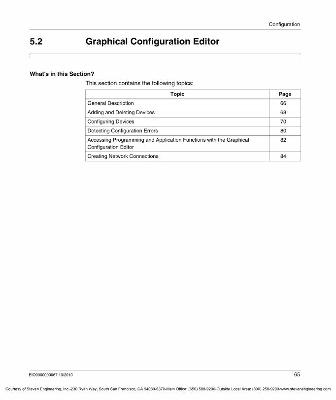
General Description of the Configuration Tab . . . . . . . . . . . . . . . . . . . . . 625.2 Graphical Configuration Editor. . . . . . . . . . . . . . . . . . . . . . . . . . . . . . . . . 65
General Description . . . . . . . . . . . . . . . . . . . . . . . . . . . . . . . . . . . . . . . . . 66Adding and Deleting Devices. . . . . . . . . . . . . . . . . . . . . . . . . . . . . . . . . . 68Configuring Devices. . . . . . . . . . . . . . . . . . . . . . . . . . . . . . . . . . . . . . . . . 70Detecting Configuration Errors. . . . . . . . . . . . . . . . . . . . . . . . . . . . . . . . . 80Accessing Programming and Application Functions with the Graphical Configuration Editor . . . . . . . . . . . . . . . . . . . . . . . . . . . . . . . . . . . . . . . . . 82Creating Network Connections . . . . . . . . . . . . . . . . . . . . . . . . . . . . . . . . 84
Chapter 6 Device Configuration with Device Type Manager (DTM) 876.1 General Information . . . . . . . . . . . . . . . . . . . . . . . . . . . . . . . . . . . . . . . . . 88
What is FDT?. . . . . . . . . . . . . . . . . . . . . . . . . . . . . . . . . . . . . . . . . . . . . . 89SoMachine as FDT Container . . . . . . . . . . . . . . . . . . . . . . . . . . . . . . . . . 90Typical Topologies. . . . . . . . . . . . . . . . . . . . . . . . . . . . . . . . . . . . . . . . . . 91Devices with Device Type Manager (DTM) . . . . . . . . . . . . . . . . . . . . . . . 93FDT Services . . . . . . . . . . . . . . . . . . . . . . . . . . . . . . . . . . . . . . . . . . . . . . 95
6.2 Main Use Cases for Configuration. . . . . . . . . . . . . . . . . . . . . . . . . . . . . . 96Device Type Manager (DTM) Installation . . . . . . . . . . . . . . . . . . . . . . . . 97Configuration Offline with the Dedicated DTM. . . . . . . . . . . . . . . . . . . . . 101Configuration Online with the Dedicated DTM. . . . . . . . . . . . . . . . . . . . . 105Configuration with Generic DTM . . . . . . . . . . . . . . . . . . . . . . . . . . . . . . . 113Hardwire Topology. . . . . . . . . . . . . . . . . . . . . . . . . . . . . . . . . . . . . . . . . . 117
6.3 FDT Options. . . . . . . . . . . . . . . . . . . . . . . . . . . . . . . . . . . . . . . . . . . . . . . 124FDT Options. . . . . . . . . . . . . . . . . . . . . . . . . . . . . . . . . . . . . . . . . . . . . . . 124
6.4 Device Configuration . . . . . . . . . . . . . . . . . . . . . . . . . . . . . . . . . . . . . . . . 126Device Configuration . . . . . . . . . . . . . . . . . . . . . . . . . . . . . . . . . . . . . . . . 126
Chapter 7 Program . . . . . . . . . . . . . . . . . . . . . . . . . . . . . . . . . . . . . . . 1297.1 General Information . . . . . . . . . . . . . . . . . . . . . . . . . . . . . . . . . . . . . . . . . 130
General Description of the Program Tab . . . . . . . . . . . . . . . . . . . . . . . . . 1307.2 Managing the Application Objects . . . . . . . . . . . . . . . . . . . . . . . . . . . . . . 133
Adding Tasks . . . . . . . . . . . . . . . . . . . . . . . . . . . . . . . . . . . . . . . . . . . . . . 134Adding and Declaring POUs . . . . . . . . . . . . . . . . . . . . . . . . . . . . . . . . . . 135Adding Libraries. . . . . . . . . . . . . . . . . . . . . . . . . . . . . . . . . . . . . . . . . . . . 137Adding and Declaring Remanent Variables. . . . . . . . . . . . . . . . . . . . . . . 140Adding a Symbol Configuration . . . . . . . . . . . . . . . . . . . . . . . . . . . . . . . . 143Adding Other Objects. . . . . . . . . . . . . . . . . . . . . . . . . . . . . . . . . . . . . . . . 144Introduction to Data Logging . . . . . . . . . . . . . . . . . . . . . . . . . . . . . . . . . . 145
7.3 Adding Devices . . . . . . . . . . . . . . . . . . . . . . . . . . . . . . . . . . . . . . . . . . . . 147Adding Controller . . . . . . . . . . . . . . . . . . . . . . . . . . . . . . . . . . . . . . . . . . . 148Adding Expansion Modules . . . . . . . . . . . . . . . . . . . . . . . . . . . . . . . . . . . 149Adding Communication Managers. . . . . . . . . . . . . . . . . . . . . . . . . . . . . . 152Adding Devices to a Communication Manager . . . . . . . . . . . . . . . . . . . . 154Adding Devices from Template . . . . . . . . . . . . . . . . . . . . . . . . . . . . . . . . 157
4 EIO0000000067 10/2010
even Engineering, Inc.-230 Ryan Way, South San Francisco, CA 94080-6370-Main Office: (650) 588-9200-Outside Local Area: (800) 258-9200-www.stevenengineering.com
Courtesy o
7.4 Managing the Libraries . . . . . . . . . . . . . . . . . . . . . . . . . . . . . . . . . . . . . . . 158Generalities About Libraries . . . . . . . . . . . . . . . . . . . . . . . . . . . . . . . . . . . 159Library Management in SoMachine. . . . . . . . . . . . . . . . . . . . . . . . . . . . . . 162Schneider Electric Libraries. . . . . . . . . . . . . . . . . . . . . . . . . . . . . . . . . . . . 165Other Libraries Used in SoMachine . . . . . . . . . . . . . . . . . . . . . . . . . . . . . 172Creating Your Own Libraries . . . . . . . . . . . . . . . . . . . . . . . . . . . . . . . . . . . 175
7.5 Managing the Communication Ports . . . . . . . . . . . . . . . . . . . . . . . . . . . . . 176Configuring the Ethernet Interface . . . . . . . . . . . . . . . . . . . . . . . . . . . . . . 177Configuring the CANopen Interface . . . . . . . . . . . . . . . . . . . . . . . . . . . . . 180Configuring the Serial Line Interfaces . . . . . . . . . . . . . . . . . . . . . . . . . . . . 186Configuring the AS-Interface. . . . . . . . . . . . . . . . . . . . . . . . . . . . . . . . . . . 190
7.6 SoMachine Commands. . . . . . . . . . . . . . . . . . . . . . . . . . . . . . . . . . . . . . . 195SoMachine Commands Providing Single Access to Your Machine . . . . . 196Description of the Build All Command. . . . . . . . . . . . . . . . . . . . . . . . . . . . 197Description of the Create Boot Application Command . . . . . . . . . . . . . . . 198Description of the USB Mass Storage Command . . . . . . . . . . . . . . . . . . . 199Description of the Import / Export Vijeo-Designer Project Commands . . . 201
7.7 SoMachine Controller-HMI Data Exchange . . . . . . . . . . . . . . . . . . . . . . . 202SoMachine Single Variable Definition . . . . . . . . . . . . . . . . . . . . . . . . . . . . 203Publishing Variables in the Controller Part . . . . . . . . . . . . . . . . . . . . . . . . 207Selecting Variables in the HMI Part. . . . . . . . . . . . . . . . . . . . . . . . . . . . . . 208Publishing Variables in the HMI Part. . . . . . . . . . . . . . . . . . . . . . . . . . . . . 209Parametrization of the Physical Media . . . . . . . . . . . . . . . . . . . . . . . . . . . 211
7.8 SoMachine Templates. . . . . . . . . . . . . . . . . . . . . . . . . . . . . . . . . . . . . . . . 212General Information about SoMachine Templates . . . . . . . . . . . . . . . . . . 213Supported Fieldbusses . . . . . . . . . . . . . . . . . . . . . . . . . . . . . . . . . . . . . . . 215Selecting SoMachine Templates for Your Project. . . . . . . . . . . . . . . . . . . 217Administration of SoMachine Templates. . . . . . . . . . . . . . . . . . . . . . . . . . 219
7.9 Managing Device Templates. . . . . . . . . . . . . . . . . . . . . . . . . . . . . . . . . . . 224Facts of Device Templates . . . . . . . . . . . . . . . . . . . . . . . . . . . . . . . . . . . . 225Adding Devices from Template . . . . . . . . . . . . . . . . . . . . . . . . . . . . . . . . . 226Creating a Device Template on the Basis of I/O Devices . . . . . . . . . . . . . 228Visualizations Suitable for Creating Device Templates. . . . . . . . . . . . . . . 229Steps to Create a Device Template . . . . . . . . . . . . . . . . . . . . . . . . . . . . . 230
7.10 Managing Function Templates . . . . . . . . . . . . . . . . . . . . . . . . . . . . . . . . . 234Facts of Function Templates. . . . . . . . . . . . . . . . . . . . . . . . . . . . . . . . . . . 235Adding Functions From Template . . . . . . . . . . . . . . . . . . . . . . . . . . . . . . . 236Application Functions as Basis for Function Templates . . . . . . . . . . . . . . 239Steps to Create a Function Template . . . . . . . . . . . . . . . . . . . . . . . . . . . . 241
7.11 Transferring and Running Applications . . . . . . . . . . . . . . . . . . . . . . . . . . . 243Transferring Applications. . . . . . . . . . . . . . . . . . . . . . . . . . . . . . . . . . . . . . 244Running Applications. . . . . . . . . . . . . . . . . . . . . . . . . . . . . . . . . . . . . . . . . 248
EIO0000000067 10/2010 5
f Steven Engineering, Inc.-230 Ryan Way, South San Francisco, CA 94080-6370-Main Office: (650) 588-9200-Outside Local Area: (800) 258-9200-www.stevenengineering.com
Courtesy of St
Chapter 8 Commissioning . . . . . . . . . . . . . . . . . . . . . . . . . . . . . . . . . 249General Description of the Commissioning Tab . . . . . . . . . . . . . . . . . . . 250Description of the Login/Logout Task . . . . . . . . . . . . . . . . . . . . . . . . . . . 253Description of the Multiple Download Task . . . . . . . . . . . . . . . . . . . . . . . 255Description of the Source Download Task. . . . . . . . . . . . . . . . . . . . . . . . 257
Chapter 9 Report . . . . . . . . . . . . . . . . . . . . . . . . . . . . . . . . . . . . . . . . . 259Report . . . . . . . . . . . . . . . . . . . . . . . . . . . . . . . . . . . . . . . . . . . . . . . . . . . 259
Part III Troubleshooting and FAQ . . . . . . . . . . . . . . . . . . . . 265Chapter 10 Generic - Troubleshooting and FAQ . . . . . . . . . . . . . . . . 267
10.1 Frequently Asked Questions . . . . . . . . . . . . . . . . . . . . . . . . . . . . . . . . . . 267Shortcuts and Menus. . . . . . . . . . . . . . . . . . . . . . . . . . . . . . . . . . . . . . . . 268Enabling and Configuring Analog Inputs on CANopen . . . . . . . . . . . . . . 270
Glossary . . . . . . . . . . . . . . . . . . . . . . . . . . . . . . . . . . . . . . . . . . . 273Index . . . . . . . . . . . . . . . . . . . . . . . . . . . . . . . . . . . . . . . . . . . 303
6 EIO0000000067 10/2010
even Engineering, Inc.-230 Ryan Way, South San Francisco, CA 94080-6370-Main Office: (650) 588-9200-Outside Local Area: (800) 258-9200-www.stevenengineering.com

§
Courtesy
Safety Information
o
Important Information
NOTICE
Read these instructions carefully, and look at the equipment to become familiar with the device before trying to install, operate, or maintain it. The following special messages may appear throughout this documentation or on the equipment to warn of potential hazards or to call attention to information that clarifies or simplifies a procedure.
EIO0000000067 10/2010 7
f Steven Engineering, Inc.-230 Ryan Way, South San Francisco, CA 94080-6370-Main Office: (650) 588-9200-Outside Local Area: (800) 258-9200-www.stevenengineering.com
Courtesy of St
PLEASE NOTE
Electrical equipment should be installed, operated, serviced, and maintained only by qualified personnel. No responsibility is assumed by Schneider Electric for any consequences arising out of the use of this material.
A qualified person is one who has skills and knowledge related to the construction and operation of electrical equipment and the installation, and has received safety training to recognize and avoid the hazards involved.
8 EIO0000000067 10/2010
even Engineering, Inc.-230 Ryan Way, South San Francisco, CA 94080-6370-Main Office: (650) 588-9200-Outside Local Area: (800) 258-9200-www.stevenengineering.com
Courtesy o
About the Book
At a Glance
Document Scope
This document describes the graphical user interface of the SoMachine software and the functions it provides. For further information, refer to the separate documents provided in the SoMachine online help.
Validity Note
This document has been updated with the release of SoMachine V2.0.
Related Documents
Title of Documentation Reference Number
Modicon M238 Logic Controller Programming Guide EIO0000000384 (ENG); EIO0000000385 (FRE); EIO0000000386 (GER); EIO0000000388 (SPA); EIO0000000387 (ITA); EIO0000000389 (CHS)
Magelis XBTGC HMI Controller Programming Guide EIO0000000632 (ENG); EIO0000000633 (FRE); EIO0000000634 (GER); EIO0000000635 (SPA); EIO0000000636 (ITA); EIO0000000637 (CHS)
Magelis XBTGT, XBTGK HMI Controller Programming Guide EIO0000000638 (ENG); EIO0000000639 (FRE); EIO0000000640 (GER); EIO0000000641 (SPA); EIO0000000642 (ITA); EIO0000000643 (CHS)
EIO0000000067 10/2010 9
f Steven Engineering, Inc.-230 Ryan Way, South San Francisco, CA 94080-6370-Main Office: (650) 588-9200-Outside Local Area: (800) 258-9200-www.stevenengineering.com
Courtesy of St
You can download these technical publications and other technical information from our website at www.schneider-electric.com.
ATV IMC Drive Controller Programming Guide EIO0000000390 (ENG); EIO0000000391 (FRE); EIO0000000392 (GER); EIO0000000393 (SPA); EIO0000000394 (ITA); EIO0000000395 (CHS)
Modicon M258 Logic Controller Programming Guide EIO0000000402 (ENG); EIO0000000403 (FRE); EIO0000000404 (GER); EIO0000000405 (SPA); EIO0000000406 (ITA); EIO0000000407 (CHS)
Modicon LMC058 Logic Controller Programming Guide EIO0000000408 (ENG); EIO0000000409 (FRE); EIO0000000410 (GER); EIO0000000411 (SPA); EIO0000000412 (ITA); EIO0000000413 (CHS)
10 EIO0000000067 10/2010
even Engineering, Inc.-230 Ryan Way, South San Francisco, CA 94080-6370-Main Office: (650) 588-9200-Outside Local Area: (800) 258-9200-www.stevenengineering.com
Courtesy o
Product Related Information
1 For additional information, refer to NEMA ICS 1.1 (latest edition), "Safety Guidelines for the Application, Installation, and Maintenance of Solid State Control" and to NEMA ICS 7.1 (latest edition), "Safety Standards for Construction and Guide for Selection, Installation and Operation of Adjustable-Speed Drive Systems" or their equivalent governing your particular location.
User Comments
We welcome your comments about this document. You can reach us by e-mail at [email protected].
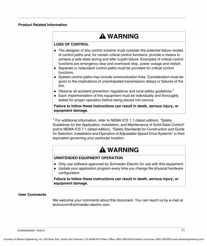
WARNINGLOSS OF CONTROL
The designer of any control scheme must consider the potential failure modes of control paths and, for certain critical control functions, provide a means to achieve a safe state during and after a path failure. Examples of critical control functions are emergency stop and overtravel stop, power outage and restart.Separate or redundant control paths must be provided for critical control functions.System control paths may include communication links. Consideration must be given to the implications of unanticipated transmission delays or failures of the link.
Observe all accident prevention regulations and local safety guidelines.1
Each implementation of this equipment must be individually and thoroughly tested for proper operation before being placed into service.
Failure to follow these instructions can result in death, serious injury, or equipment damage.
WARNINGUNINTENDED EQUIPMENT OPERATION
Only use software approved by Schneider Electric for use with this equipment.Update your application program every time you change the physical hardware configuration.
Failure to follow these instructions can result in death, serious injury, or equipment damage.
EIO0000000067 10/2010 11
f Steven Engineering, Inc.-230 Ryan Way, South San Francisco, CA 94080-6370-Main Office: (650) 588-9200-Outside Local Area: (800) 258-9200-www.stevenengineering.com

Courtesy of St
12 EIO0000000067 10/2010
even Engineering, Inc.-230 Ryan Way, South San Francisco, CA 94080-6370-Main Office: (650) 588-9200-Outside Local Area: (800) 258-9200-www.stevenengineering.com
EIO0000000067 10/2010
Courtesy of Steven Engineering, Inc.-230 Ryan Way, South San Francisco, CA 94080-6370-Main Office: (650) 588-9200-Outside Local Ar
I
Introduction
EIO0000000067 10/2010
Introduction
What's in this Part?
This part contains the following chapters:
Chapter Chapter Name Page
1 Introduction about Programming 15
2 Managing Projects with SoMachine 2.0 17
13
ea: (800) 258-9200-www.stevenengineering.com

Introduction
14 EIO0000000067 10/2010
Courtesy of Steven Engineering, Inc.-230 Ryan Way, South San Francisco, CA 94080-6370-Main Office: (650) 588-9200-Outside Local Area: (800) 258-9200-www.stevenengineering.com
EIO0000000067 10/2010
Courtesy of Steven Engineering, Inc.-230 Ryan Way, South San Francisco, CA 94080-6370-Main Office: (650) 588-9200-Outside Local Ar
1
Introduction about Programming
EIO0000000067 10/2010
Introduction about Programming
Programming
Overview
SoMachine allows you to configure, program and commission entire machines in a single software environment.
It consists of 2 parts dedicated to specific programming tasks:SoMachine part for controller programmingVijeo-Designer part for HMI programming
User Documentation
This programming manual describes the SoMachine user interface and functions. It is part of the SoMachine online help.
To start the SoMachine online help, click the ? button in the SoMachine screen or select the Help command from the General Functions Menu (see page 25).
To start the online help from the Program screen of SoMachine, use the Help menu or press the F1 key.
To start the Vijeo-Designer online help, select a suitable command from the Help menu or press the F1 key when you are in the Vijeo-Designer application.
For general information on SoMachine, like for example system requirements, installation and supported devices, refer to section Introduction of the SoMachine online help.
For detailed information on the controllers and integrated HMIs supported by SoMachine, refer to section Hardware User Guides of the SoMachine online help.
For detailed information on SoMachine libraries, refer to section Functions & Libraries User Manuals of the SoMachine online help.
15
ea: (800) 258-9200-www.stevenengineering.com

Introduction about Programming
16 EIO0000000067 10/2010
Courtesy of Steven Engineering, Inc.-230 Ryan Way, South San Francisco, CA 94080-6370-Main Office: (650) 588-9200-Outside Local Area: (800) 258-9200-www.stevenengineering.com
EIO0000000067 10/2010
Courtesy of Steven Engineering, Inc.-230 Ryan Way, South San Francisco, CA 94080-6370-Main Office: (650) 588-9200-Outside Local Ar
2
Managing Projects with SoMachine 2.0
EIO0000000067 10/2010
Managing Projects with SoMachine 2.0
Main Tasks
Overview
SoMachine 2.0 provides a completely new graphical user interface that is based on the 3 main tasks it has been designed for:
configuring projectsprogramming projectscommissioning machines
Configuring Projects
SoMachine 2.0 provides tools that are intended to assist you in creating new projects fast and easily.
It provides for project start-upa variety of tested validated documented architectures (a dedicated TVDA Finder tool assists you in selecting the architecture that most appropriately suits your individual project),a variety of application projects for conveying, hoisting, and packaging that provide basic configurations for these applications,some examples that provide basic projects for making yourself familiar with SoMachine.
Once the project is created, SoMachine provides extensive possibilities to add textual and graphical information to each project file. This additional information enables you to distinguish projects avoiding the need to open them when you have to select the suitable project out of those that are available on your computer.
For easy configuration of your project, SoMachine provides a graphical configuration editor that allows to add and configure devices in a comfortable way.
17
ea: (800) 258-9200-www.stevenengineering.com
Managing Projects with SoMachine 2.0
Courtesy of St
Programming Projects
For programming projects, the conventional CoDeSys graphical user interface is integrated in the SoMachine graphical user interface. It provides the general programming and controller configuration functions. For configuring HMI controllers, Vijeo-Designer is used.
Commissioning Machines
SoMachine provides components that are especially dedicated to machine commissioning. These components provide only those functions that are required for this task, like login into the devices, configuring last parameters and up- or downloading software and/or sourcecode.
18 EIO0000000067 10/2010
even Engineering, Inc.-230 Ryan Way, South San Francisco, CA 94080-6370-Main Office: (650) 588-9200-Outside Local Area: (800) 258-9200-www.stevenengineering.com
EIO0000000067 10/2010
Courtesy of Steven Engineering, Inc.-230 Ryan Way, South San Francisco, CA 94080-6370-Main Office: (650) 588-9200-Outside Local Ar
II
Manage Your Project
EIO0000000067 10/2010
Manage Your Project
What's in this Part?
This part contains the following chapters:
Chapter Chapter Name Page
3 Home 21
4 Properties 53
5 Configuration 61
6 Device Configuration with Device Type Manager (DTM) 87
7 Program 129
8 Commissioning 249
9 Report 259
19
ea: (800) 258-9200-www.stevenengineering.com

Manage Your Project
20 EIO0000000067 10/2010
Courtesy of Steven Engineering, Inc.-230 Ryan Way, South San Francisco, CA 94080-6370-Main Office: (650) 588-9200-Outside Local Area: (800) 258-9200-www.stevenengineering.com
EIO0000000067 10/2010
Courtesy of Steven Engineering, Inc.-230 Ryan Way, South San Francisco, CA 94080-6370-Main Office: (650) 588-9200-Outside Local Ar
3
Home
EIO0000000067 10/2010
Home
What's in this Chapter?
This chapter contains the following sections:
Section Topic Page
3.1 General Information 22
3.2 Show Existing Machine 27
3.3 Create New Machine 31
3.4 Machine Workflow 41
3.5 Learning Center 50
21
ea: (800) 258-9200-www.stevenengineering.com
Home
Courtesy of St
3.1 General Information
What's in this Section?
This section contains the following topics:
Topic Page
General Description of the Main Selection Screen 23
Accessing General Functions 25
22 EIO0000000067 10/2010
even Engineering, Inc.-230 Ryan Way, South San Francisco, CA 94080-6370-Main Office: (650) 588-9200-Outside Local Area: (800) 258-9200-www.stevenengineering.com
Home
Courtesy o
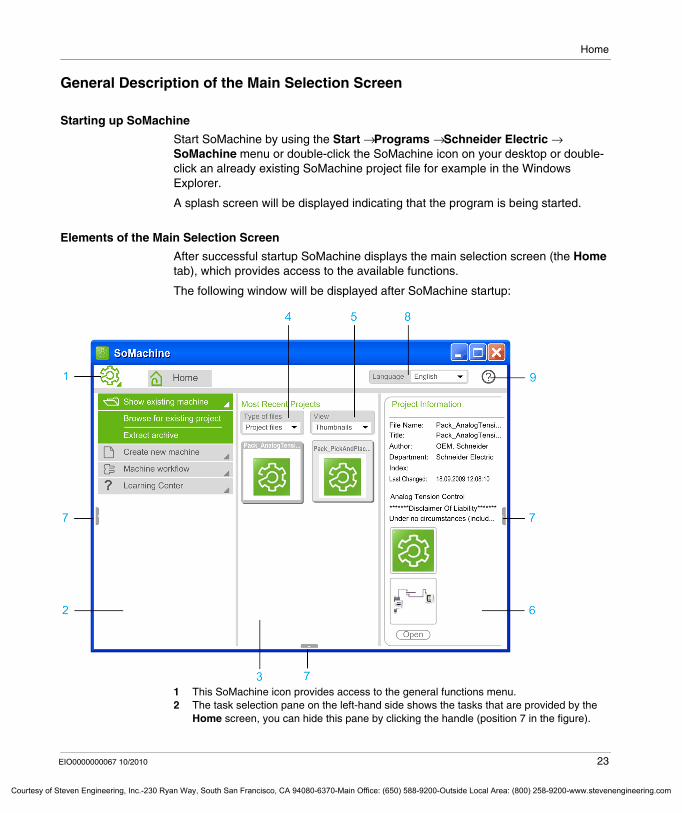
General Description of the Main Selection Screen
Starting up SoMachine
Start SoMachine by using the Start → Programs → Schneider Electric → SoMachine menu or double-click the SoMachine icon on your desktop or double-click an already existing SoMachine project file for example in the Windows Explorer.
A splash screen will be displayed indicating that the program is being started.
Elements of the Main Selection Screen
After successful startup SoMachine displays the main selection screen (the Home tab), which provides access to the available functions.
The following window will be displayed after SoMachine startup:
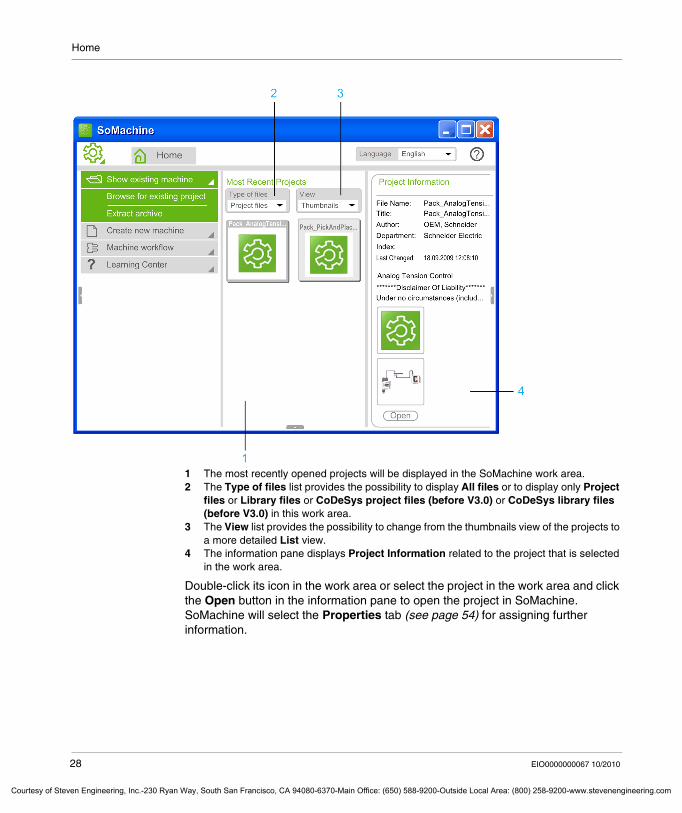
1 This SoMachine icon provides access to the general functions menu.2 The task selection pane on the left-hand side shows the tasks that are provided by the
Home screen, you can hide this pane by clicking the handle (position 7 in the figure).
EIO0000000067 10/2010 23
f Steven Engineering, Inc.-230 Ryan Way, South San Francisco, CA 94080-6370-Main Office: (650) 588-9200-Outside Local Area: (800) 258-9200-www.stevenengineering.com
Home
Courtesy of St
3 The work area in the middle is intended to always be visible. It provides access to the most recently opened projects.
4 The Type of files list provides the possibility to display All files or to display only Project files or Library files or CoDeSys project files (before V3.0) or CoDeSys library files (before V3.0) in this work area.
5 The View list provides the possibility to change from the thumbnails view of the projects to a more detailed List view.
6 The information pane on the right-hand side shows further information on the project that is currently selected in the work area, you can hide this pane by clicking the handle.
7 Handles to hide or display the task selection pane on the right-hand side, the information pane on the left-hand side and the message pane at the bottom of the window that is not visible by default in the startup screen.
8 The Language list allows you to change the language of the SoMachine user interface, after you have changed the language you must restart SoMachine for the changes to become valid
9 The ? icon provides quick access to the SoMachine online help.
Tasks of the Home Tab
The task selection pane on the left-hand side of the main selection screen groups the SoMachine functions in folders according to the tasks you can perform with them.
Closing SoMachine Projects
The Home tab also serves for closing your SoMachine project. Just click the Home tab when you are inside a project, and the project will be closed, returning you to the main selection screen as indicated in the above figure.
Tasks of the Home Screen
Sub-Tasks
Show existing machine
This folder provides sub-tasks for opening an already existing SoMachine project, and for opening a project archive file (refer to the Show Existing Machine (see page 27) chapter for details).
Create new machine
This folder provides sub-tasks for creating a new SoMachine project file or library file either from scratch or by using a template. Refer to the Create New Machine (see page 31) chapter for details.
Machine workflow This folder provides sub-tasks that are especially dedicated to commissioning a machine. Further commands that are beyond commissioning tasks are not available from this folder. Refer to the Machine Workflow (see page 41) chapter for details.
Learning Center This folder provides further information on SoMachine. Refer to the Learning Center (see page 50) chapter for details.
24 EIO0000000067 10/2010
even Engineering, Inc.-230 Ryan Way, South San Francisco, CA 94080-6370-Main Office: (650) 588-9200-Outside Local Area: (800) 258-9200-www.stevenengineering.com
Home
Courtesy o
Accessing General Functions
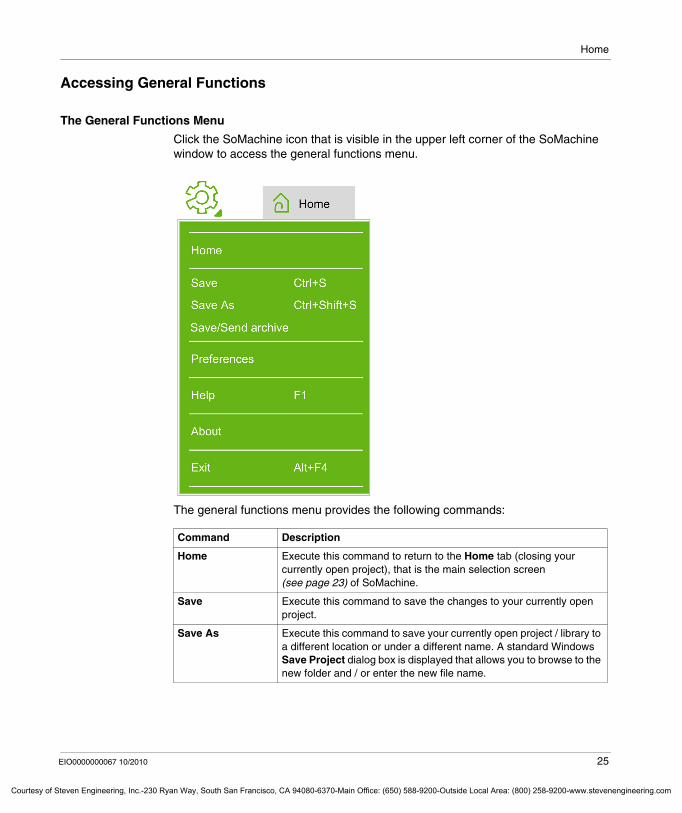
The General Functions Menu
Click the SoMachine icon that is visible in the upper left corner of the SoMachine window to access the general functions menu.
The general functions menu provides the following commands:
Command Description
Home Execute this command to return to the Home tab (closing your currently open project), that is the main selection screen (see page 23) of SoMachine.
Save Execute this command to save the changes to your currently open project.
Save As Execute this command to save your currently open project / library to a different location or under a different name. A standard Windows Save Project dialog box is displayed that allows you to browse to the new folder and / or enter the new file name.
EIO0000000067 10/2010 25
f Steven Engineering, Inc.-230 Ryan Way, South San Francisco, CA 94080-6370-Main Office: (650) 588-9200-Outside Local Area: (800) 258-9200-www.stevenengineering.com
Home
Courtesy of St
Save/Send archive Execute this command to create an archive file of the SoMachine project that is currently open and:
to save the archive file to a connected drive by using the Save button of the Project Archive dialog boxorto create a temporary archive file that is attached to an empty e-mail by using the Send button of the Project Archive dialog box. This e-mail is automatically created by SoMachine if the Messaging Application Programming Interface (MAPI) is correctly installed.
Preferences Execute this command to configure:the Preferred Path where to open and save SoMachine projects.the Online Polling Interval (ms) that is the time span that has to elapse between 2 attempts to poll the connected devices.the Routing Step Width that defines the grid size of the graphical configuration editor (see page 65). Select a value between 15 (wide grid) and 50 (small grid), bearing in mind that a smaller grid (a higher value) leads to longer times for refreshing the graphical representation of your configuration.the Timeout for routing that defines the time the graphical configuration editor (see page 65) is allowed to (re)route the graphical representation of your configuration in order to create right-angled connecting lines. If this timeout elapses before the routing process is finished, the remaining lines will be displayed without right-angles.the Stop Gateway on Exit check box defines the behavior of the gateway after closing the last instance of SoMachine:
check box checked (default)The gateway is automatically stopped when you exit the last SoMachine instance. If other instances of SoMachine are still running, using the gateway, it will not be stopped.check box uncheckedThe gateway will not be stopped automatically when you exit the last SoMachine instance.
general settings by clicking the Options button.
Help Execute this command to open the SoMachine online help.
About Execute this command to open the About dialog box that provides information about the currently installed SoMachine version as well as license and technical information.
Exit Execute this command to close SoMachine.
Command Description
26 EIO0000000067 10/2010
even Engineering, Inc.-230 Ryan Way, South San Francisco, CA 94080-6370-Main Office: (650) 588-9200-Outside Local Area: (800) 258-9200-www.stevenengineering.com
Home
Courtesy o
3.2 Show Existing Machine
Show Existing Machine
Sub-Tasks
With the Show existing machine task you can open an already existing project.
It includes the following sub-tasks:Browse for existing project to open an existing SoMachine projectExtract archive to open an existing SoMachine project archive file
Opening a Most Recent Project
The work area provides quick access to the SoMachine projects you had opened before. You can define the number of projects that will be displayed here in the Options dialog box that is accessible via the general functions menu (see page 25) Preferences → Options → Load and Save → Display [1-16] items in most recently used list.
EIO0000000067 10/2010 27
f Steven Engineering, Inc.-230 Ryan Way, South San Francisco, CA 94080-6370-Main Office: (650) 588-9200-Outside Local Area: (800) 258-9200-www.stevenengineering.com
Home
Courtesy of St
1 The most recently opened projects will be displayed in the SoMachine work area.2 The Type of files list provides the possibility to display All files or to display only Project
files or Library files or CoDeSys project files (before V3.0) or CoDeSys library files (before V3.0) in this work area.
3 The View list provides the possibility to change from the thumbnails view of the projects to a more detailed List view.
4 The information pane displays Project Information related to the project that is selected in the work area.
Double-click its icon in the work area or select the project in the work area and click the Open button in the information pane to open the project in SoMachine. SoMachine will select the Properties tab (see page 54) for assigning further information.
28 EIO0000000067 10/2010
even Engineering, Inc.-230 Ryan Way, South San Francisco, CA 94080-6370-Main Office: (650) 588-9200-Outside Local Area: (800) 258-9200-www.stevenengineering.com
Home
Courtesy o
Browsing for Existing Project
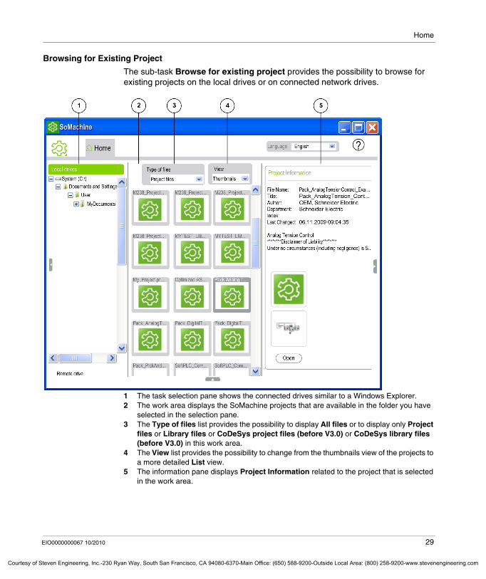
The sub-task Browse for existing project provides the possibility to browse for existing projects on the local drives or on connected network drives.
1 The task selection pane shows the connected drives similar to a Windows Explorer.2 The work area displays the SoMachine projects that are available in the folder you have
selected in the selection pane.3 The Type of files list provides the possibility to display All files or to display only Project
files or Library files or CoDeSys project files (before V3.0) or CoDeSys library files (before V3.0) in this work area.
4 The View list provides the possibility to change from the thumbnails view of the projects to a more detailed List view.
5 The information pane displays Project Information related to the project that is selected in the work area.
EIO0000000067 10/2010 29
f Steven Engineering, Inc.-230 Ryan Way, South San Francisco, CA 94080-6370-Main Office: (650) 588-9200-Outside Local Area: (800) 258-9200-www.stevenengineering.com
Home
Courtesy of St
In the task selection pane browse to the folder that contains the SoMachine project you want to open. Double-click its icon in the work area or select the project in the work area and click the Open button in the information pane to open the project in SoMachine. SoMachine will select the Properties tab (see page 54) for assigning further information.
To access network drives that are not mapped on your PC, proceed as follows:
Opening a Project Archive
The sub-task Extract Archive provides the possibility to open existing SoMachine project archive files.
To open an existing SoMachine project archive file proceed as follows:
Step Action
1 Click the Remote drive task in the task selection pane.
2 Enter the server name and the subfolder name(s) according to the following syntax in the text box: \\servername\foldername
3 Click the Open button.Result: The content of the server / subfolder will be displayed in the task selection pane similar to a Windows Explorer.
Step Action
1 Select the Extract Archive sub-task from the task selection pane.Result: The Extract Archive dialog box will be displayed.
2 Browse to the folder that contains the project archive file you want to open.
3 Select the project archive file and click the Open button.Result: The Project Archive dialog box opens.
4 In the Project Archive dialog box select the Referenced devices and Referenced libraries you want to extract from the archive file and click the Extract button.Result: SoMachine extracts the selected items from the archive file and automatically opens the project.
30 EIO0000000067 10/2010
even Engineering, Inc.-230 Ryan Way, South San Francisco, CA 94080-6370-Main Office: (650) 588-9200-Outside Local Area: (800) 258-9200-www.stevenengineering.com
Home
Courtesy o
3.3 Create New Machine
What's in this Section?
This section contains the following topics:
Topic Page
Create New Machine Sub-Tasks 32
Start with Empty Project 33
Start with TVD Architecture 34
Start with Application 36
Start with Existing Project 38
Start with Example 39
EIO0000000067 10/2010 31
f Steven Engineering, Inc.-230 Ryan Way, South San Francisco, CA 94080-6370-Main Office: (650) 588-9200-Outside Local Area: (800) 258-9200-www.stevenengineering.com
Home
Courtesy of St
Create New Machine Sub-Tasks
Sub-Tasks
With the Create new machine task you can create a new project either from scratch or by using a project template.
It includes the following sub-tasks:Start with empty projectStart with TVD architectureStart with applicationStart with existing projectStart with example
32 EIO0000000067 10/2010
even Engineering, Inc.-230 Ryan Way, South San Francisco, CA 94080-6370-Main Office: (650) 588-9200-Outside Local Area: (800) 258-9200-www.stevenengineering.com
Home
Courtesy o
Start with Empty Project
Function of the Sub-Task
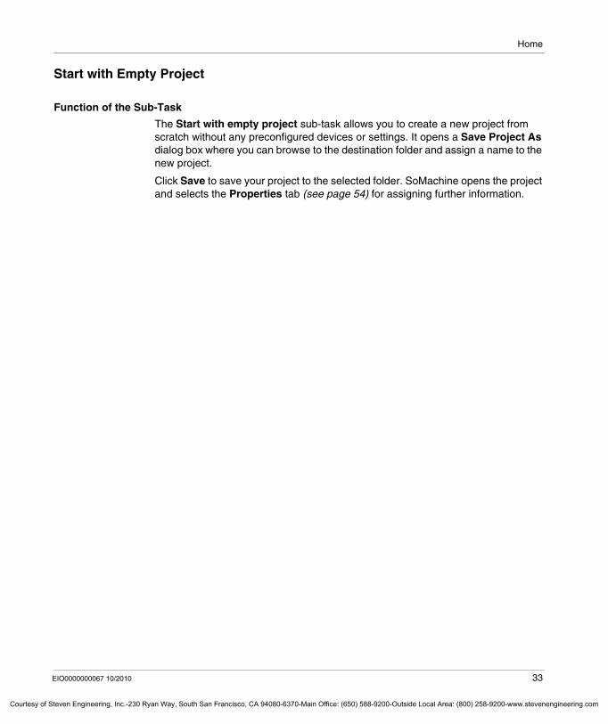
The Start with empty project sub-task allows you to create a new project from scratch without any preconfigured devices or settings. It opens a Save Project As dialog box where you can browse to the destination folder and assign a name to the new project.
Click Save to save your project to the selected folder. SoMachine opens the project and selects the Properties tab (see page 54) for assigning further information.
EIO0000000067 10/2010 33
f Steven Engineering, Inc.-230 Ryan Way, South San Francisco, CA 94080-6370-Main Office: (650) 588-9200-Outside Local Area: (800) 258-9200-www.stevenengineering.com
Home
Courtesy of St
Start with TVD Architecture
Function of the Sub-Task
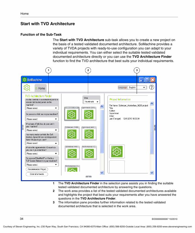
The Start with TVD Architecture sub-task allows you to create a new project on the basis of a tested validated documented architecture. SoMachine provides a variety of TVDA projects with ready-to-use configuration you can adapt to your individual requirements. You can either select the suitable tested validated documented architecture directly or you can use the TVD Architecture Finder function to find the TVD architecture that best suits your individual requirements.
1 The TVD Architecture Finder in the selection pane assists you in finding the suitable tested validated documented architecture by answering the questions.
2 The work area provides a list of the tested validated documented architectures available and highlights the project that best suits your requirements after you have answered the questions in the TVD Architecture Finder.
3 The information pane provides further information related to the tested validated documented architecture that is selected in the work area.
34 EIO0000000067 10/2010
even Engineering, Inc.-230 Ryan Way, South San Francisco, CA 94080-6370-Main Office: (650) 588-9200-Outside Local Area: (800) 258-9200-www.stevenengineering.com
Home
Courtesy o
Creating a New Project on the Basis of a TVD Architecture
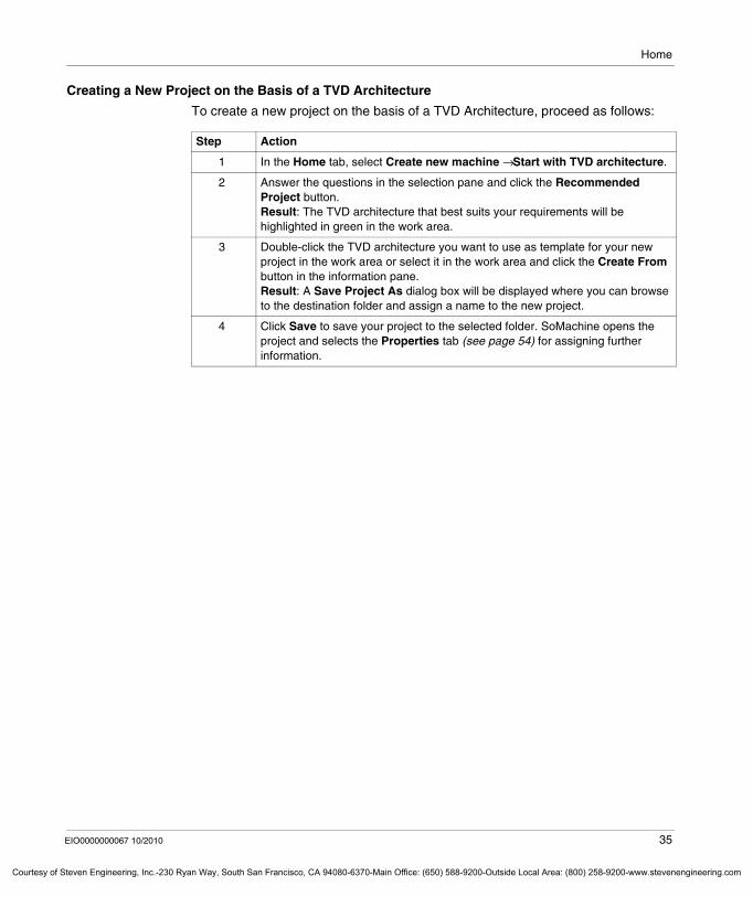
To create a new project on the basis of a TVD Architecture, proceed as follows:
Step Action
1 In the Home tab, select Create new machine → Start with TVD architecture.
2 Answer the questions in the selection pane and click the Recommended Project button.Result: The TVD architecture that best suits your requirements will be highlighted in green in the work area.
3 Double-click the TVD architecture you want to use as template for your new project in the work area or select it in the work area and click the Create From button in the information pane.Result: A Save Project As dialog box will be displayed where you can browse to the destination folder and assign a name to the new project.
4 Click Save to save your project to the selected folder. SoMachine opens the project and selects the Properties tab (see page 54) for assigning further information.
EIO0000000067 10/2010 35
f Steven Engineering, Inc.-230 Ryan Way, South San Francisco, CA 94080-6370-Main Office: (650) 588-9200-Outside Local Area: (800) 258-9200-www.stevenengineering.com
Home
Courtesy of St
Start with Application
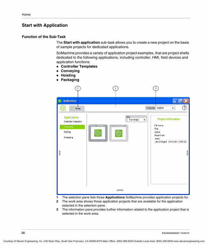
Function of the Sub-Task
The Start with application sub-task allows you to create a new project on the basis of sample projects for dedicated applications.
SoMachine provides a variety of application project examples, that are project shells dedicated to the following applications, including controller, HMI, field devices and application functions:
Controller TemplatesConveyingHoistingPackaging
1 The selection pane lists those Applications SoMachine provides application projects for. 2 The work area shows those application projects that are available for the application
selected in the selection pane.3 The information pane provides further information related to the application project that is
selected in the work area.
36 EIO0000000067 10/2010
even Engineering, Inc.-230 Ryan Way, South San Francisco, CA 94080-6370-Main Office: (650) 588-9200-Outside Local Area: (800) 258-9200-www.stevenengineering.com
Home
Courtesy o
Creating a new Project on the Basis of an Application Project
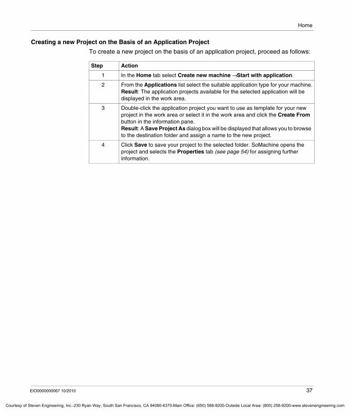
To create a new project on the basis of an application project, proceed as follows:
Step Action
1 In the Home tab select Create new machine → Start with application.
2 From the Applications list select the suitable application type for your machine.Result: The application projects available for the selected application will be displayed in the work area.
3 Double-click the application project you want to use as template for your new project in the work area or select it in the work area and click the Create From button in the information pane.Result: A Save Project As dialog box will be displayed that allows you to browse to the destination folder and assign a name to the new project.
4 Click Save to save your project to the selected folder. SoMachine opens the project and selects the Properties tab (see page 54) for assigning further information.
EIO0000000067 10/2010 37
f Steven Engineering, Inc.-230 Ryan Way, South San Francisco, CA 94080-6370-Main Office: (650) 588-9200-Outside Local Area: (800) 258-9200-www.stevenengineering.com

Home
Courtesy of St
Start with Existing Project
Function of the Sub-Task
The Start with existing project sub-task allows you to create a new project that is based on an already existing project. Browse for existing project and / or library files on the local drives or on connected network drives.
To prevent the existing project / library from being overwritten, a Save as dialog box is automatically displayed when you save the new project / library. Enter a new name to create a new project / library file.
This sub-task is identical to the sub-task Browse for existing project in the Show existing machine task. For further information refer to the description of this sub-task (see page 29).
38 EIO0000000067 10/2010
even Engineering, Inc.-230 Ryan Way, South San Francisco, CA 94080-6370-Main Office: (650) 588-9200-Outside Local Area: (800) 258-9200-www.stevenengineering.com
Home
Courtesy o
Start with Example
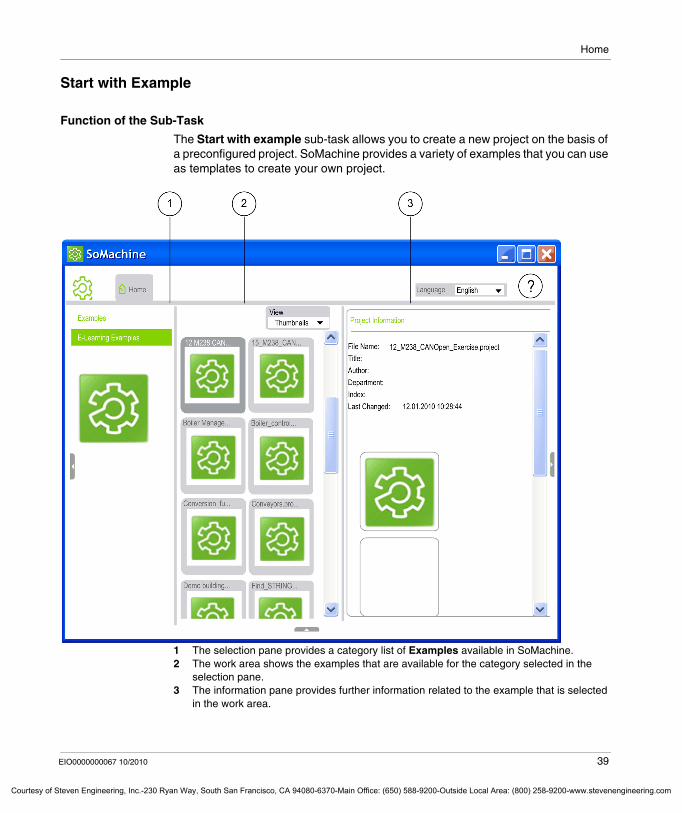
Function of the Sub-Task
The Start with example sub-task allows you to create a new project on the basis of a preconfigured project. SoMachine provides a variety of examples that you can use as templates to create your own project.
1 The selection pane provides a category list of Examples available in SoMachine.2 The work area shows the examples that are available for the category selected in the
selection pane.3 The information pane provides further information related to the example that is selected
in the work area.
EIO0000000067 10/2010 39
f Steven Engineering, Inc.-230 Ryan Way, South San Francisco, CA 94080-6370-Main Office: (650) 588-9200-Outside Local Area: (800) 258-9200-www.stevenengineering.com
Home
Courtesy of St
Creating a new Project on the Basis of an Example
To create a new project on the basis of an example, proceed as follows:
Step Action
1 In the Home tab select Create new machine → Start with example.
2 Select a category in the Examples list to display the examples available for this category in the work area.
3 To use an example as template for your new project, double-click its icon in the work area or select it in the work area and click the Create From button in the information pane.Result: A Save Project As dialog box will be displayed that allows you to browse to the destination folder and assign a name to the new project.
4 Click Save to save your project to the selected folder. SoMachine opens the project and selects the Properties tab (see page 54) for assigning further information.
40 EIO0000000067 10/2010
even Engineering, Inc.-230 Ryan Way, South San Francisco, CA 94080-6370-Main Office: (650) 588-9200-Outside Local Area: (800) 258-9200-www.stevenengineering.com
Home
Courtesy o
3.4 Machine Workflow
What's in this Section?
This section contains the following topics:
Topic Page
Machine Workflow Sub-Tasks 42
Commission Machine - Start with Project 43
Commission Machine - Upload Project from Device 45
Update Firmware 48
EIO0000000067 10/2010 41
f Steven Engineering, Inc.-230 Ryan Way, South San Francisco, CA 94080-6370-Main Office: (650) 588-9200-Outside Local Area: (800) 258-9200-www.stevenengineering.com
Home
Courtesy of St
Machine Workflow Sub-Tasks
Sub-Tasks of the Machine Workflow Task
The Machine Workflow task provides sub-tasks that are especially dedicated to commissioning a machine. Further tasks that are beyond commissioning tasks are not available from this folder. It is, for example, not possible to modify the SoMachine project.
The Machine Workflow task includes the following sub-tasks:Commission machine - start with projectCommission machine - upload project from deviceUpdate firmware
42 EIO0000000067 10/2010
even Engineering, Inc.-230 Ryan Way, South San Francisco, CA 94080-6370-Main Office: (650) 588-9200-Outside Local Area: (800) 258-9200-www.stevenengineering.com
Home
Courtesy o
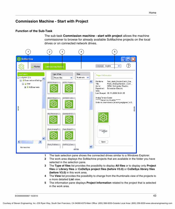
Commission Machine - Start with Project
Function of the Sub-Task
The sub-task Commission machine - start with project allows the machine commissioner to browse for already available SoMachine projects on the local drives or on connected network drives.
1 The task selection pane shows the connected drives similar to a Windows Explorer.2 The work area displays the SoMachine projects that are available in the folder you have
selected in the selection pane.3 The Type of files list provides the possibility to display All files or to display only Project
files or Library files or CoDeSys project files (before V3.0) or CoDeSys library files (before V3.0) in this work area.
4 The View list provides the possibility to change from the thumbnails view of the projects to a more detailed List view.
5 The information pane displays Project Information related to the project that is selected in the work area.
EIO0000000067 10/2010 43
f Steven Engineering, Inc.-230 Ryan Way, South San Francisco, CA 94080-6370-Main Office: (650) 588-9200-Outside Local Area: (800) 258-9200-www.stevenengineering.com
Home
Courtesy of St
Opening a Project for Machine Commissioning
To open a project for commissioning a machine proceed as follows:
Step Action
1 In the Home tab select Machine workflow → Commission machine - start with project.Result: The connected drives are shown in its task selection pane, similar to a Windows Explorer, allowing to browse for the project file.
2 Browse to the folder that contains the project file for the new machine.
3 Open the project by double-clicking its icon in the work area or by selecting it in the work area and clicking the Open button in the information pane.Result: SoMachine opens the project showing only the Commissioning Machine tab (see page 250) with commands restricted to perform commissioning tasks.
44 EIO0000000067 10/2010
even Engineering, Inc.-230 Ryan Way, South San Francisco, CA 94080-6370-Main Office: (650) 588-9200-Outside Local Area: (800) 258-9200-www.stevenengineering.com
Home
Courtesy o
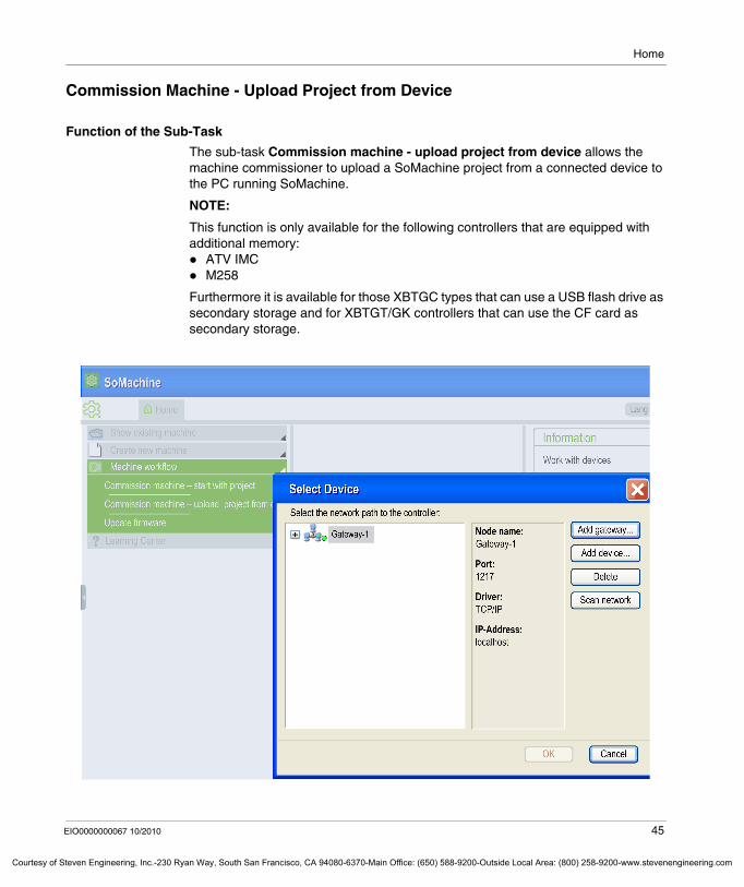
Commission Machine - Upload Project from Device
Function of the Sub-Task
The sub-task Commission machine - upload project from device allows the machine commissioner to upload a SoMachine project from a connected device to the PC running SoMachine.
NOTE:
This function is only available for the following controllers that are equipped with additional memory:
ATV IMCM258
Furthermore it is available for those XBTGC types that can use a USB flash drive as secondary storage and for XBTGT/GK controllers that can use the CF card as secondary storage.
EIO0000000067 10/2010 45
f Steven Engineering, Inc.-230 Ryan Way, South San Francisco, CA 94080-6370-Main Office: (650) 588-9200-Outside Local Area: (800) 258-9200-www.stevenengineering.com
Home
Courtesy of St
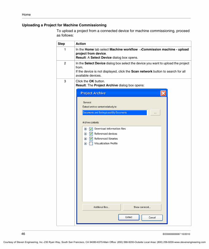
Uploading a Project for Machine Commissioning
To upload a project from a connected device for machine commissioning, proceed as follows:
Step Action
1 In the Home tab select Machine workflow → Commission machine - upload project from device.Result: A Select Device dialog box opens.
2 In the Select Device dialog box select the device you want to upload the project from.If the device is not displayed, click the Scan network button to search for all available devices.
3 Click the OK button.Result: The Project Archive dialog box opens:
46 EIO0000000067 10/2010
even Engineering, Inc.-230 Ryan Way, South San Francisco, CA 94080-6370-Main Office: (650) 588-9200-Outside Local Area: (800) 258-9200-www.stevenengineering.com
Home
Courtesy o
For more information on the sub-tasks available in the Commissioning tab refer to the Commissioning chapter (see page 249).
4 In the Project Archive dialog box click the ... button to browse to the folder on your SoMachine PC where the uploaded project will be saved.
5 In the Archive contents section select those contents of the project archive that will be uploaded to the selected folder. To achieve this, select the check boxes for each item you want to upload.
6 Click Extract to upload the selected contents of the project archive to the selected folder.
7 During the upload process you will be prompted to confirm any overwriting of files already available in the specified folder.
8 Confirm the message prompting you to open the uploaded project.Result: The Commissioning tab opens, displaying the project configuration in the work area.
Step Action
EIO0000000067 10/2010 47
f Steven Engineering, Inc.-230 Ryan Way, South San Francisco, CA 94080-6370-Main Office: (650) 588-9200-Outside Local Area: (800) 258-9200-www.stevenengineering.com
Home
Courtesy of St
Update Firmware
Function of the Sub-Task
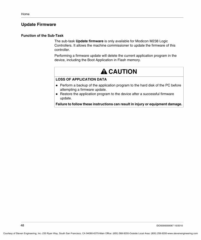
The sub-task Update firmware is only available for Modicon M238 Logic Controllers. It allows the machine commissioner to update the firmware of this controller.
Performing a firmware update will delete the current application program in the device, including the Boot Application in Flash memory.
CAUTIONLOSS OF APPLICATION DATA
Perform a backup of the application program to the hard disk of the PC before attempting a firmware update.Restore the application program to the device after a successful firmware update.
Failure to follow these instructions can result in injury or equipment damage.
48 EIO0000000067 10/2010
even Engineering, Inc.-230 Ryan Way, South San Francisco, CA 94080-6370-Main Office: (650) 588-9200-Outside Local Area: (800) 258-9200-www.stevenengineering.com
Home
Courtesy o
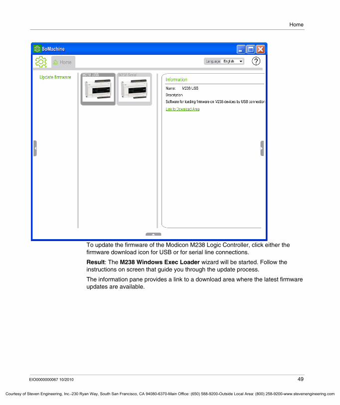
To update the firmware of the Modicon M238 Logic Controller, click either the firmware download icon for USB or for serial line connections.
Result: The M238 Windows Exec Loader wizard will be started. Follow the instructions on screen that guide you through the update process.
The information pane provides a link to a download area where the latest firmware updates are available.
EIO0000000067 10/2010 49
f Steven Engineering, Inc.-230 Ryan Way, South San Francisco, CA 94080-6370-Main Office: (650) 588-9200-Outside Local Area: (800) 258-9200-www.stevenengineering.com
Home
Courtesy of St
3.5 Learning Center
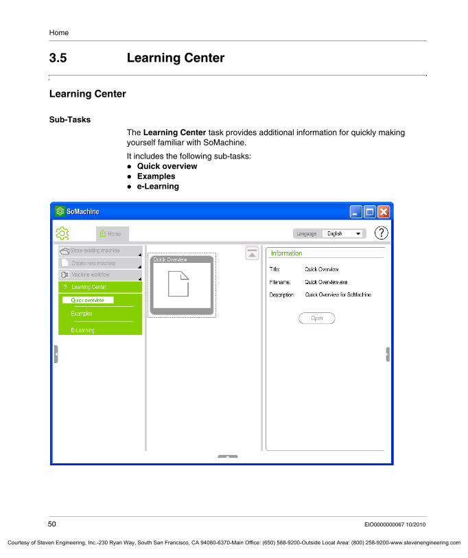
Learning Center
Sub-Tasks
The Learning Center task provides additional information for quickly making yourself familiar with SoMachine.
It includes the following sub-tasks:Quick overviewExamplese-Learning
50 EIO0000000067 10/2010
even Engineering, Inc.-230 Ryan Way, South San Francisco, CA 94080-6370-Main Office: (650) 588-9200-Outside Local Area: (800) 258-9200-www.stevenengineering.com
Home
Courtesy o
Quick Overview
The Quick overview sub-task provides a short film that introduces the SoMachine user interface as well as its main functions in about 2 minutes time. To run this film, no additional software is required on your PC.
Examples
The Examples sub-task provides sample projects together with PDF files documenting these SoMachine projects.
NOTE: Please note that the Adobe ReaderTM is required to open these documents. This reader is not part of the SoMachine installation but can be downloaded from http://www.adobe.com/go/EN_US-H-GET-READER.
e-Learning
The e-Learning sub-task provides an interactive training that shows you how to use SoMachine. To run this training, no additional software is required on your PC.
EIO0000000067 10/2010 51
f Steven Engineering, Inc.-230 Ryan Way, South San Francisco, CA 94080-6370-Main Office: (650) 588-9200-Outside Local Area: (800) 258-9200-www.stevenengineering.com

Home
Courtesy of St
52 EIO0000000067 10/2010
even Engineering, Inc.-230 Ryan Way, South San Francisco, CA 94080-6370-Main Office: (650) 588-9200-Outside Local Area: (800) 258-9200-www.stevenengineering.com
EIO0000000067 10/2010
Courtesy of Steven Engineering, Inc.-230 Ryan Way, South San Francisco, CA 94080-6370-Main Office: (650) 588-9200-Outside Local Ar
4
Properties
EIO0000000067 10/2010
Properties
What's in this Chapter?
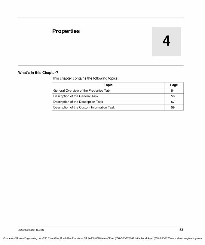
This chapter contains the following topics:
Topic Page
General Overview of the Properties Tab 54
Description of the General Task 56
Description of the Description Task 57
Description of the Custom Information Task 59
53
ea: (800) 258-9200-www.stevenengineering.com
Properties
Courtesy of St
General Overview of the Properties Tab
The Properties Tab
The Properties tab allows you to enter additional project information. The textual and graphical information entered here are optional. As this information is always displayed in the information pane for the project selected in the work area, it helps to identify the individual projects, avoiding the need to open them. This tab is only displayed after you have opened a project.
The Properties tab provides the following tasks:GeneralDescriptionCustom Information
54 EIO0000000067 10/2010
even Engineering, Inc.-230 Ryan Way, South San Francisco, CA 94080-6370-Main Office: (650) 588-9200-Outside Local Area: (800) 258-9200-www.stevenengineering.com
Properties
Courtesy o
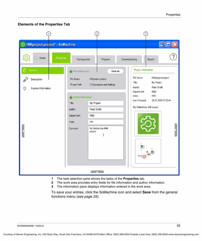
Elements of the Properties Tab
1 The task selection pane shows the tasks of the Properties tab.2 The work area provides entry fields for file information and author information.3 The information pane displays information entered in the work area.
To save your entries, click the SoMachine icon and select Save from the general functions menu (see page 25).
EIO0000000067 10/2010 55
f Steven Engineering, Inc.-230 Ryan Way, South San Francisco, CA 94080-6370-Main Office: (650) 588-9200-Outside Local Area: (800) 258-9200-www.stevenengineering.com
Properties
Courtesy of St
Description of the General Task
The General Task
The General task allows you to save the project file to a different location or under a different name and provides the option to add author information. The work area provides the following sections:
File InformationAuthor Information
File Information
The section File Information displays the name of your project file and the folder it is saved in. To save your project to a different location or under a different name, click the Save as button, navigate to the preferred folder and save your project file.
Author Information
The section Author Information provides entry fields for optional information you consider relevant. Your entries are displayed in the section Project Information on the right side.
Note:
The following characters are not allowed in the Title and Author text boxes:( (left parenthesis)) (right parenthesis), (comma)
To save the information entered in the Properties tab, click the SoMachine icon and select Save from the general functions menu (see page 25).
56 EIO0000000067 10/2010
even Engineering, Inc.-230 Ryan Way, South San Francisco, CA 94080-6370-Main Office: (650) 588-9200-Outside Local Area: (800) 258-9200-www.stevenengineering.com
Properties
Courtesy o
Description of the Description Task
The Description Task
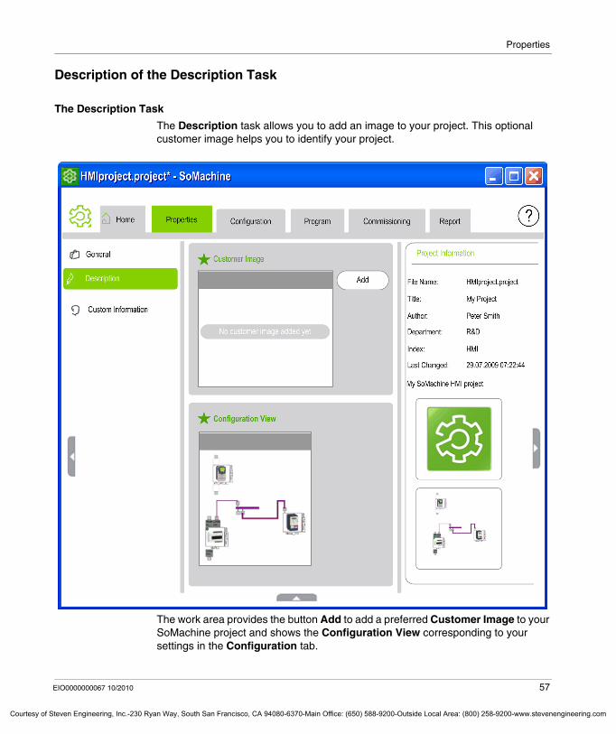
The Description task allows you to add an image to your project. This optional customer image helps you to identify your project.
The work area provides the button Add to add a preferred Customer Image to your SoMachine project and shows the Configuration View corresponding to your settings in the Configuration tab.
EIO0000000067 10/2010 57
f Steven Engineering, Inc.-230 Ryan Way, South San Francisco, CA 94080-6370-Main Office: (650) 588-9200-Outside Local Area: (800) 258-9200-www.stevenengineering.com
Properties
Courtesy of St
Customer Image
The section Customer Image allows you to add an image to your SoMachine project.
Adding a Customer Image
To add a new image to your project, proceed as follows:
Changing or Removing a Customer Image
To replace the customer image for the project with a new one, click the Change button and browse to the location of the new image.
Click the Remove button to remove your image.
Configuration View
The Configuration View section shows an overview of your project configuration corresponding to your settings in the Configuration tab (see page 62).
Step Action
1 Click the Add button.Result: The dialog box Add customer image to project opens.
2 Browse to your destination folder, select a preferred image, and click Open.Result: The customer image is displayed in the work area and in the information pane.
58 EIO0000000067 10/2010
even Engineering, Inc.-230 Ryan Way, South San Francisco, CA 94080-6370-Main Office: (650) 588-9200-Outside Local Area: (800) 258-9200-www.stevenengineering.com
Properties
Courtesy o
Description of the Custom Information Task
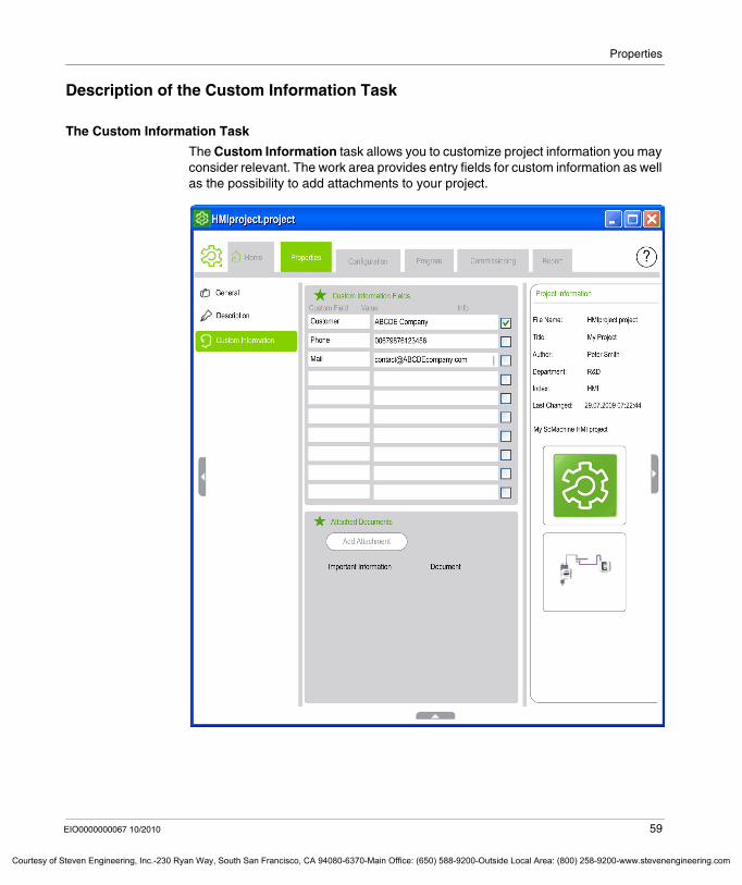
The Custom Information Task
The Custom Information task allows you to customize project information you may consider relevant. The work area provides entry fields for custom information as well as the possibility to add attachments to your project.
EIO0000000067 10/2010 59
f Steven Engineering, Inc.-230 Ryan Way, South San Francisco, CA 94080-6370-Main Office: (650) 588-9200-Outside Local Area: (800) 258-9200-www.stevenengineering.com
Properties
Courtesy of St
Custom Information Fields
The Custom Information Fields are text boxes for any optional information you might want to give to personalize your project. The fields and their values you define here can be displayed in the information pane on the right-hand side if you activate the respective Info check box.
In the Custom Field text boxes enter a name for a new field you want to create. Enter the content that should appear in this field in the Value text boxes.
For every line of information you want to be displayed as Project Information in the information pane on the right-hand side, select the check box in the Info column.
Attached Documents
Click the Add Attachment button to attach 1 or more documents to your project file.
A dialog box will be displayed, where you can browse to the destination folder.
After you have attached a file to your project, the section Add Attachment displays a check box for Important Information as well as the icons for:
View attachment, which opens the attached file.Save attachment as file, which opens a Save as dialog box.Remove attachment from project, which deletes the link between the project and the attached file.
Important Information
The section Attached Documents provides the check box Important Information for each of the attached documents. For each document you consider as important to read, select the check box. The task menu will then show a small SoMachine icon next to the task Custom Information to indicate that it includes important information.
60 EIO0000000067 10/2010
even Engineering, Inc.-230 Ryan Way, South San Francisco, CA 94080-6370-Main Office: (650) 588-9200-Outside Local Area: (800) 258-9200-www.stevenengineering.com
EIO0000000067 10/2010
Courtesy of Steven Engineering, Inc.-230 Ryan Way, South San Francisco, CA 94080-6370-Main Office: (650) 588-9200-Outside Local Ar
5
Configuration
EIO0000000067 10/2010
Configuration
What's in this Chapter?
This chapter contains the following sections:
Section Topic Page
5.1 General Information 62
5.2 Graphical Configuration Editor 65
61
ea: (800) 258-9200-www.stevenengineering.com
Configuration
Courtesy of St
5.1 General Information
General Description of the Configuration Tab
Overview
The Configuration tab is only displayed after you have opened a SoMachine project.
It consists of a graphical configuration editor that provides necessary functions to perform the entire hardware and network configuration of your machine. The configuration settings performed here will also be available in the CoDeSys and Vijeo-Designer Program tab.
62 EIO0000000067 10/2010
even Engineering, Inc.-230 Ryan Way, South San Francisco, CA 94080-6370-Main Office: (650) 588-9200-Outside Local Area: (800) 258-9200-www.stevenengineering.com
Configuration
Courtesy o
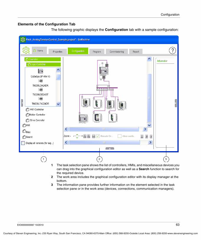
Elements of the Configuration Tab
The following graphic displays the Configuration tab with a sample configuration:
1 The task selection pane shows the list of controllers, HMIs, and miscellaneous devices you can drag into the graphical configuration editor as well as a Search function to search for the required device.
2 The work area includes the graphical configuration editor with its display manager at the bottom.
3 The information pane provides further information on the element selected in the task selection pane or in the work area (devices, connections, communication managers).
EIO0000000067 10/2010 63
f Steven Engineering, Inc.-230 Ryan Way, South San Francisco, CA 94080-6370-Main Office: (650) 588-9200-Outside Local Area: (800) 258-9200-www.stevenengineering.com
Configuration
Courtesy of St
Task Selection Pane
The task selection pane of the Configuration tab lists the devices you can add to the configuration in the graphical configuration editor grouped by type into Controller, HMI, and Misc (miscellaneous) devices. To add a device, select it in this list and drag it to the work area.
To ease finding the suitable device icon, SoMachine additionally provides a Search function.
To search for a device, enter its name in the text box surrounded by asterisks and click the Search button. SoMachine will return a list of devices meeting the search phrase you entered or will display a message indicating that no devices were found.
64 EIO0000000067 10/2010
even Engineering, Inc.-230 Ryan Way, South San Francisco, CA 94080-6370-Main Office: (650) 588-9200-Outside Local Area: (800) 258-9200-www.stevenengineering.com
Configuration
Courtesy o
5.2 Graphical Configuration Editor
What's in this Section?
This section contains the following topics:
Topic Page
General Description 66
Adding and Deleting Devices 68
Configuring Devices 70
Detecting Configuration Errors 80
Accessing Programming and Application Functions with the Graphical Configuration Editor
82
Creating Network Connections 84
EIO0000000067 10/2010 65
f Steven Engineering, Inc.-230 Ryan Way, South San Francisco, CA 94080-6370-Main Office: (650) 588-9200-Outside Local Area: (800) 258-9200-www.stevenengineering.com
Configuration
Courtesy of St
General Description
Overview
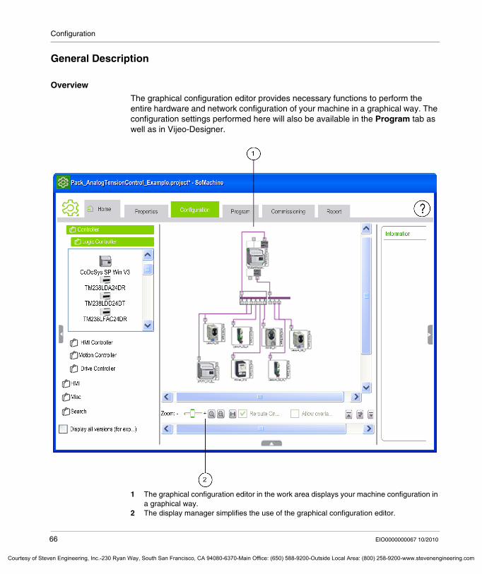
The graphical configuration editor provides necessary functions to perform the entire hardware and network configuration of your machine in a graphical way. The configuration settings performed here will also be available in the Program tab as well as in Vijeo-Designer.
1 The graphical configuration editor in the work area displays your machine configuration in a graphical way.
2 The display manager simplifies the use of the graphical configuration editor.
66 EIO0000000067 10/2010
even Engineering, Inc.-230 Ryan Way, South San Francisco, CA 94080-6370-Main Office: (650) 588-9200-Outside Local Area: (800) 258-9200-www.stevenengineering.com
Configuration
Courtesy o
When you start creating a new project from scratch, the graphical configuration editor will be empty. It will then prompt you to drag a device from the list on the left-hand side into this empty area.
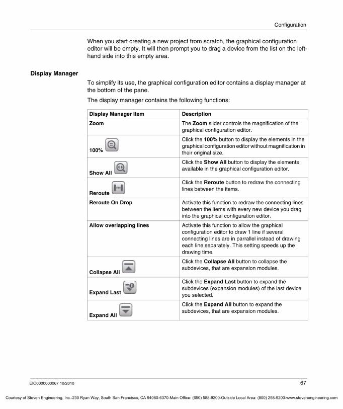
Display Manager
To simplify its use, the graphical configuration editor contains a display manager at the bottom of the pane.
The display manager contains the following functions:
Display Manager Item Description
Zoom The Zoom slider controls the magnification of the graphical configuration editor.
100%
Click the 100% button to display the elements in the graphical configuration editor without magnification in their original size.
Show All
Click the Show All button to display the elements available in the graphical configuration editor.
Reroute
Click the Reroute button to redraw the connecting lines between the items.
Reroute On Drop Activate this function to redraw the connecting lines between the items with every new device you drag into the graphical configuration editor.
Allow overlapping lines Activate this function to allow the graphical configuration editor to draw 1 line if several connecting lines are in parrallel instead of drawing each line separately. This setting speeds up the drawing time.
Collapse All
Click the Collapse All button to collapse the subdevices, that are expansion modules.
Expand Last
Click the Expand Last button to expand the subdevices (expansion modules) of the last device you selected.
Expand All
Click the Expand All button to expand the subdevices, that are expansion modules.
EIO0000000067 10/2010 67
f Steven Engineering, Inc.-230 Ryan Way, South San Francisco, CA 94080-6370-Main Office: (650) 588-9200-Outside Local Area: (800) 258-9200-www.stevenengineering.com
Configuration
Courtesy of St
Adding and Deleting Devices
Overview
The Configuration tab includes the graphical configuration editor that allows to perform machine configuration in a graphical way.
When adding or deleting devices in the controller configuration, SoMachine automatically adjusts the memory allocations for the devices. If you are adding or deleting devices to or from an existing program, you must take into account any adjustments made to I/O memory within your program.
NOTE: Schneider Electric highly recommends the use of symbolic addressing instead of immediate addressing. This may help to avoid extensive program modifications and to limit the possibility of incorrect programming instructions once a program configuration is modified by adding or deleting I/O or other devices.
Adding Devices
To add a device, proceed as follows:
NOTE: If you add an HMI device to your graphical configuration editor, Vijeo-Designer will automatically be started in the background.
WARNINGUNINTENDED EQUIPMENT OPERATION
Inspect and modify as necessary any immediate addresses used in the program after modifying the configuration.
Failure to follow these instructions can result in death, serious injury, or equipment damage.
Step Action
1 Select the device you want to add to your machine configuration from the catalog list on the left-hand side of the Configuration tab. Further information concerning the selected device will be displayed in the information pane on the right-hand side.
2 Drag the device icon to the graphical configuration editor in the middle of the Configuration tab.Result: The device is added to the machine configuration and can be moved freely with the left mouse button. You can now configure the device.
68 EIO0000000067 10/2010
even Engineering, Inc.-230 Ryan Way, South San Francisco, CA 94080-6370-Main Office: (650) 588-9200-Outside Local Area: (800) 258-9200-www.stevenengineering.com
Configuration
Courtesy o
Assigning a Name to the Device
To assign a name to your device in the graphical configuration editor, right-click the device and select Rename from the context menu, or select the device and click the default name below the device a second time to edit the text field.
Result: You can now edit the default name below the device icon (for example MyController), and enter a name of your choice.
Deleting Devices
To delete a device from the graphical configuration editor, right-click it and select Delete from the context menu, or select the device in the editor and press the delete key on your keyboard. If you confirm this action, the device as well as the network lines to which the device is connected will be deleted from the graphical configuration editor.
EIO0000000067 10/2010 69
f Steven Engineering, Inc.-230 Ryan Way, South San Francisco, CA 94080-6370-Main Office: (650) 588-9200-Outside Local Area: (800) 258-9200-www.stevenengineering.com
Configuration
Courtesy of St
Configuring Devices
Overview
The graphical configuration editor provides access to configuration dialog boxes of the devices.
Configuring Device Parameters
To configure the device you added to the graphical configuration editor, you can either double-click the device or right-click the device and select Edit parameters from the context menu. SoMachine will then open the Parameters configuration dialog box for your device. The tasks displayed on the left-hand side in the task selection pane vary depending on the selected device.
70 EIO0000000067 10/2010
even Engineering, Inc.-230 Ryan Way, South San Francisco, CA 94080-6370-Main Office: (650) 588-9200-Outside Local Area: (800) 258-9200-www.stevenengineering.com
Configuration
Courtesy o
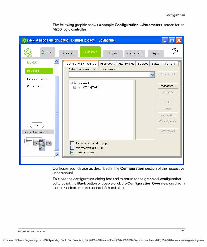
The following graphic shows a sample Configuration → Parameters screen for an M238 logic controller.
Configure your device as described in the Configuration section of the respective user manual.
To close the configuration dialog box and to return to the graphical configuration editor, click the Back button or double-click the Configuration Overview graphic in the task selection pane on the left-hand side.
EIO0000000067 10/2010 71
f Steven Engineering, Inc.-230 Ryan Way, South San Francisco, CA 94080-6370-Main Office: (650) 588-9200-Outside Local Area: (800) 258-9200-www.stevenengineering.com
Configuration
Courtesy of St
Configuring Embedded Functions
To configure embedded functions of your device, like mapping inputs and outputs as well as configuring high speed counters, pulse train output or pulse width modulation, select in the device configuration screen the entry Embedded Functions. Select the suitable sub entry from this list and configure the parameters as described in the Input / Output Configuration (HSC, PTO, PWM) sections of the respective hardware Programming Guide.
NOTE: Schneider Electric highly recommends the use of symbolic addressing instead of immediate addressing while programming. This may help to avoid extensive program modifications and to limit the possibility of incorrect programming instructions once a program’s configuration is being modified by adding or deleting I/O or other devices.
Configuring Communication Settings
To configure the communication ports of your device, select in the device configuration the entry Communication. Select the suitable sub entry (Serial Line, Ethernet, CANopen etc.) from this list and configure the Physical Settings as well as Protocol Settings of the port as described in the respective hardware user guide.
In the Protocol Settings screen SoMachine provides a Remove/Change Protocol button that opens the following dialog box to change or remove the configured protocol.
You can also open this dialog box by clicking the port of an already available device in the graphical configuration editor. But please note that this leads to a new configuration of the port and removes the already available configured communication settings.
WARNINGUNINTENDED EQUIPMENT OPERATION
Inspect and modify as necessary any immediate addresses used in the program after modifying the configuration.
Failure to follow these instructions can result in death, serious injury, or equipment damage.
72 EIO0000000067 10/2010
even Engineering, Inc.-230 Ryan Way, South San Francisco, CA 94080-6370-Main Office: (650) 588-9200-Outside Local Area: (800) 258-9200-www.stevenengineering.com
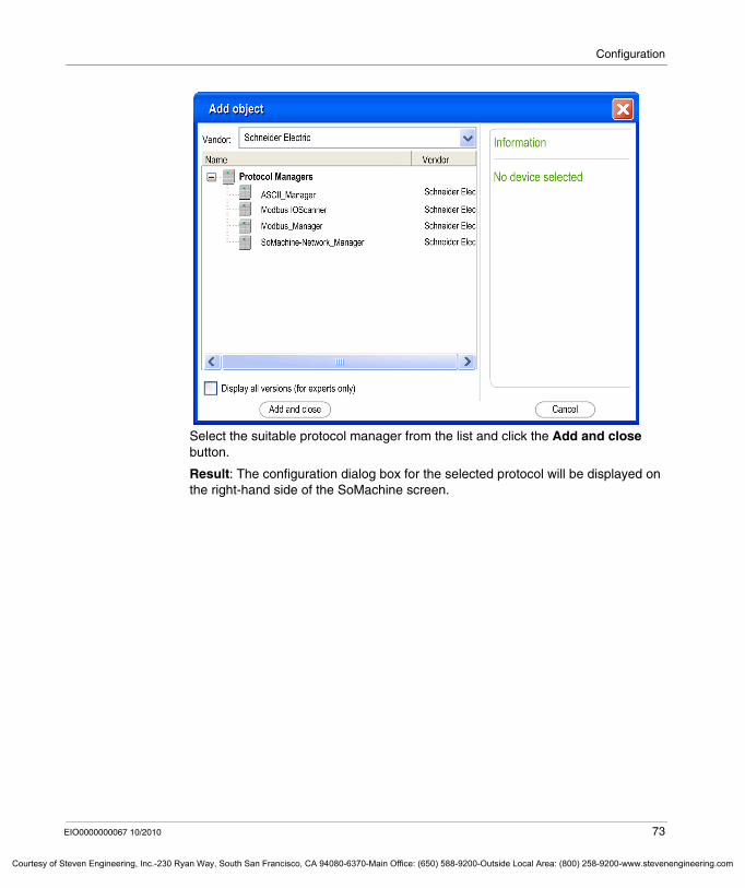
Configuration
Courtesy o
Select the suitable protocol manager from the list and click the Add and close button.
Result: The configuration dialog box for the selected protocol will be displayed on the right-hand side of the SoMachine screen.
EIO0000000067 10/2010 73
f Steven Engineering, Inc.-230 Ryan Way, South San Francisco, CA 94080-6370-Main Office: (650) 588-9200-Outside Local Area: (800) 258-9200-www.stevenengineering.com
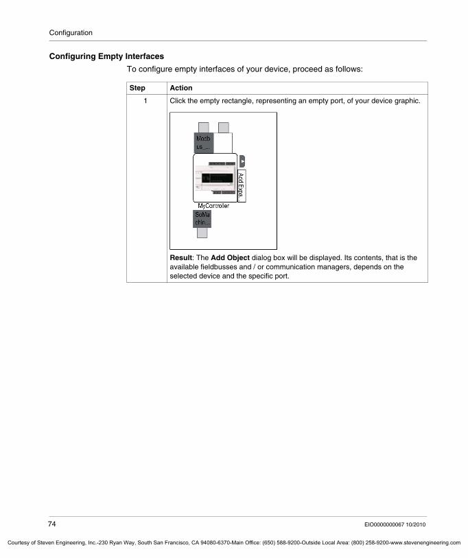
Configuration
Courtesy of St
Configuring Empty Interfaces
To configure empty interfaces of your device, proceed as follows:
Step Action
1 Click the empty rectangle, representing an empty port, of your device graphic.
Result: The Add Object dialog box will be displayed. Its contents, that is the available fieldbusses and / or communication managers, depends on the selected device and the specific port.
74 EIO0000000067 10/2010
even Engineering, Inc.-230 Ryan Way, South San Francisco, CA 94080-6370-Main Office: (650) 588-9200-Outside Local Area: (800) 258-9200-www.stevenengineering.com
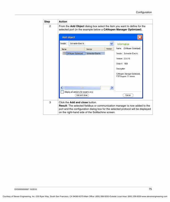
Configuration
Courtesy o
2 From the Add Object dialog box select the item you want to define for the selected port (in the example below a CANopen Manager Optimized).
3 Click the Add and close button.Result: The selected fieldbus or communication manager is now added to the port and the configuration dialog box for the selected protocol will be displayed on the right-hand side of the SoMachine screen.
Step Action
EIO0000000067 10/2010 75
f Steven Engineering, Inc.-230 Ryan Way, South San Francisco, CA 94080-6370-Main Office: (650) 588-9200-Outside Local Area: (800) 258-9200-www.stevenengineering.com
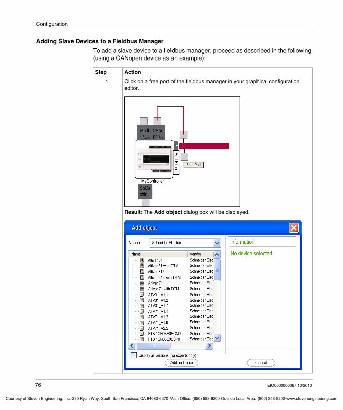
Configuration
Courtesy of St
Adding Slave Devices to a Fieldbus Manager
To add a slave device to a fieldbus manager, proceed as described in the following (using a CANopen device as an example):
Step Action
1 Click on a free port of the fieldbus manager in your graphical configuration editor.
Result: The Add object dialog box will be displayed.
76 EIO0000000067 10/2010
even Engineering, Inc.-230 Ryan Way, South San Francisco, CA 94080-6370-Main Office: (650) 588-9200-Outside Local Area: (800) 258-9200-www.stevenengineering.com
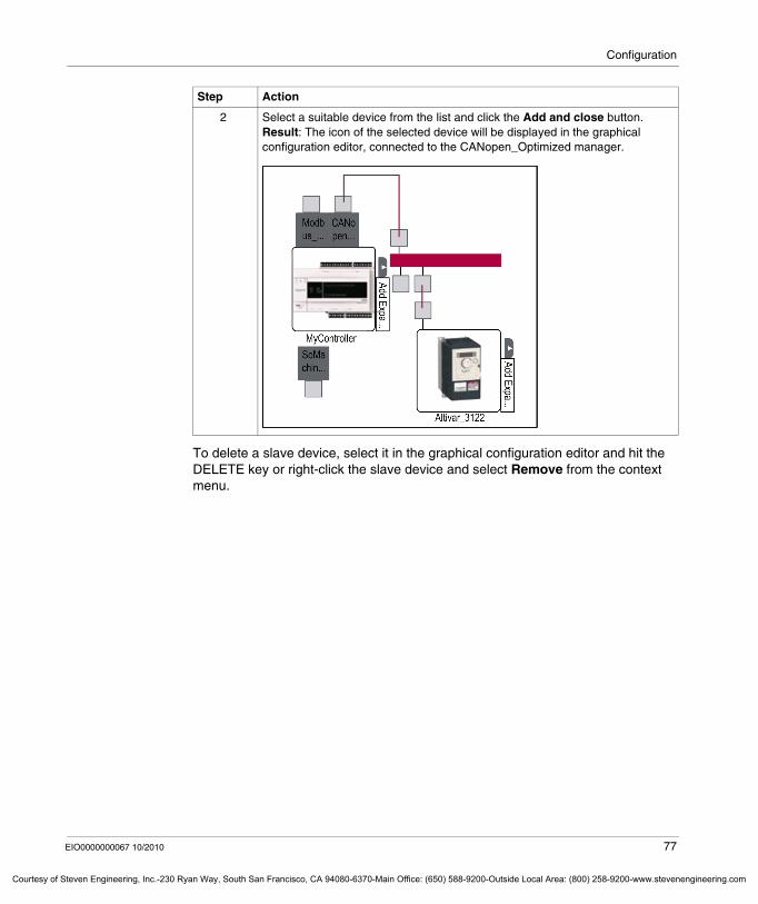
Configuration
Courtesy o
To delete a slave device, select it in the graphical configuration editor and hit the DELETE key or right-click the slave device and select Remove from the context menu.
2 Select a suitable device from the list and click the Add and close button.Result: The icon of the selected device will be displayed in the graphical configuration editor, connected to the CANopen_Optimized manager.
Step Action
EIO0000000067 10/2010 77
f Steven Engineering, Inc.-230 Ryan Way, South San Francisco, CA 94080-6370-Main Office: (650) 588-9200-Outside Local Area: (800) 258-9200-www.stevenengineering.com
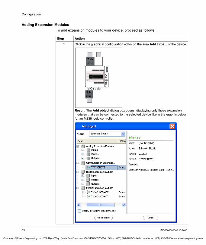
Configuration
Courtesy of St
Adding Expansion Modules
To add expansion modules to your device, proceed as follows:
Step Action
1 Click in the graphical configuration editor on the area Add Expa... of the device.
Result: The Add object dialog box opens, displaying only those expansion modules that can be connected to the selected device like in the graphic below for an M238 logic controller.
78 EIO0000000067 10/2010
even Engineering, Inc.-230 Ryan Way, South San Francisco, CA 94080-6370-Main Office: (650) 588-9200-Outside Local Area: (800) 258-9200-www.stevenengineering.com
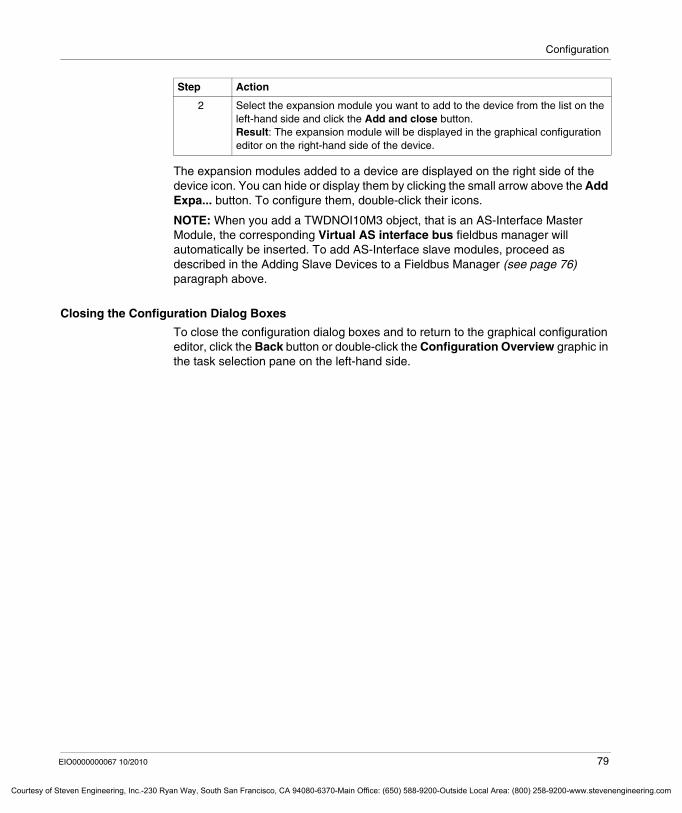
Configuration
Courtesy o
The expansion modules added to a device are displayed on the right side of the device icon. You can hide or display them by clicking the small arrow above the Add Expa... button. To configure them, double-click their icons.
NOTE: When you add a TWDNOI10M3 object, that is an AS-Interface Master Module, the corresponding Virtual AS interface bus fieldbus manager will automatically be inserted. To add AS-Interface slave modules, proceed as described in the Adding Slave Devices to a Fieldbus Manager (see page 76) paragraph above.
Closing the Configuration Dialog Boxes
To close the configuration dialog boxes and to return to the graphical configuration editor, click the Back button or double-click the Configuration Overview graphic in the task selection pane on the left-hand side.
2 Select the expansion module you want to add to the device from the list on the left-hand side and click the Add and close button.Result: The expansion module will be displayed in the graphical configuration editor on the right-hand side of the device.
Step Action
EIO0000000067 10/2010 79
f Steven Engineering, Inc.-230 Ryan Way, South San Francisco, CA 94080-6370-Main Office: (650) 588-9200-Outside Local Area: (800) 258-9200-www.stevenengineering.com
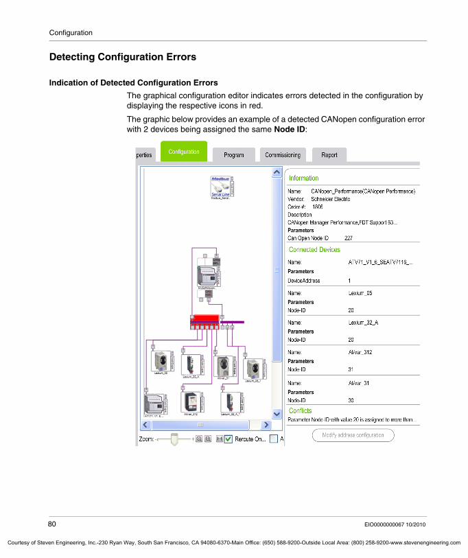
Configuration
Courtesy of St
Detecting Configuration Errors
Indication of Detected Configuration Errors
The graphical configuration editor indicates errors detected in the configuration by displaying the respective icons in red.
The graphic below provides an example of a detected CANopen configuration error with 2 devices being assigned the same Node ID:
80 EIO0000000067 10/2010
even Engineering, Inc.-230 Ryan Way, South San Francisco, CA 94080-6370-Main Office: (650) 588-9200-Outside Local Area: (800) 258-9200-www.stevenengineering.com
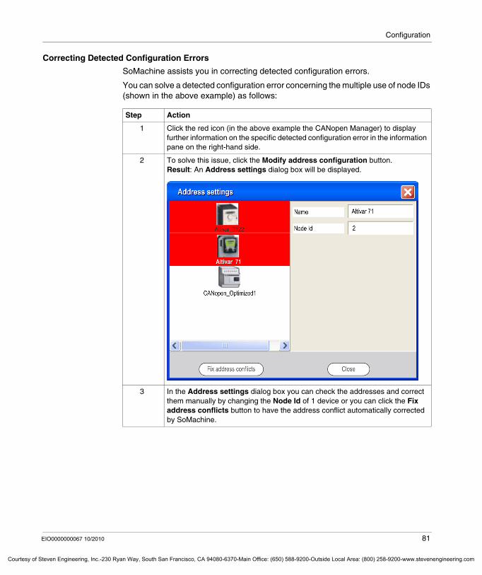
Configuration
Courtesy o
Correcting Detected Configuration Errors
SoMachine assists you in correcting detected configuration errors.
You can solve a detected configuration error concerning the multiple use of node IDs (shown in the above example) as follows:
Step Action
1 Click the red icon (in the above example the CANopen Manager) to display further information on the specific detected configuration error in the information pane on the right-hand side.
2 To solve this issue, click the Modify address configuration button.Result: An Address settings dialog box will be displayed.
3 In the Address settings dialog box you can check the addresses and correct them manually by changing the Node Id of 1 device or you can click the Fix address conflicts button to have the address conflict automatically corrected by SoMachine.
EIO0000000067 10/2010 81
f Steven Engineering, Inc.-230 Ryan Way, South San Francisco, CA 94080-6370-Main Office: (650) 588-9200-Outside Local Area: (800) 258-9200-www.stevenengineering.com
Configuration
Courtesy of St
Accessing Programming and Application Functions with the Graphical Configuration Editor
Overview
The graphical configuration editor provides direct access to the CoDeSys programming environment.
Programming Logic
To program logic for a device in the graphical configuration editor, right-click the device and select Program → Application from the context menu.
Result: The SoMachine Program tab opens, providing access to the CoDeSys programming interface.
Selecting the Active Application
In case there are several applications in your machine configuration, the graphical configuration editor provides the possibility to define which one should be the active application.
To define 1 application as active application, right-click a device in the graphical configuration editor and select from the list Set active application the application you want to be the active application.
Result: A green circle is displayed in the graphical configuration editor to indicate the active application.
Adding an Application
If your device does not yet have an application, you can create a new application as follows: Right-click the device in the graphical configuration editor and select the command Add application from the context menu. In the Add application dialog box enter a name for your new application and click Open.
82 EIO0000000067 10/2010
even Engineering, Inc.-230 Ryan Way, South San Francisco, CA 94080-6370-Main Office: (650) 588-9200-Outside Local Area: (800) 258-9200-www.stevenengineering.com
Configuration
Courtesy o
Updating Firmware
To update the firmware of your M238 controller, right-click the device in the graphical configuration editor and select the command Update firmware from the context menu. The M238 OS Loader Wizard will be started, guiding you through the update process.
Performing a firmware update will delete the current application program in the device, including the Boot Application in Flash memory.
Updating the Version of the Device
To update your device to the latest software version that is available, right-click the device in the graphical configuration editor and select the command Update Device Version from the context menu.
This command always initiates an upgrade to the latest version that is available. It is not possible to upgrade a device to an intermediate version.
Red circles in the upper right corner of the device icons indicate that the device is not running the latest software version that is available. After you have executed the Update Device Version command, the red circle will disappear.
CAUTIONLOSS OF APPLICATION DATA
Perform a backup of the application program to the hard disk of the PC before attempting a firmware update.Restore the application program to the device after a successful firmware update.
Failure to follow these instructions can result in injury or equipment damage.
EIO0000000067 10/2010 83
f Steven Engineering, Inc.-230 Ryan Way, South San Francisco, CA 94080-6370-Main Office: (650) 588-9200-Outside Local Area: (800) 258-9200-www.stevenengineering.com
Configuration
Courtesy of St
Creating Network Connections
Overview
The graphical configuration editor provides easy connection of communication ports by simply drawing lines between them.
It automatically checks the compatibility of the ports to be connected and issues error detection messages as tooltips if it detects any incompatibility.
Creating Network Connections
To create network connections with the graphical configuration editor, proceed as follows:
Step Action
1 Move the cursor on the communication port of the device you want to connect.Result: The cursor will change to a crosshair cursor. The type of the communication port will be indicated in a tooltip.
2 Click on the communication port you want to connect and keep the left mouse button pressed.Result: The cursor converts into a pencil and draws a line when being moved.
3 Drag the pencil cursor to the communication port of the device or module you want to connect your device to.Result: The pencil cursor draws a line between the 2 ports.
4 Release the left mouse button when the pencil cursor is over the communication port of the second device.Result: The pencil is converted into a normal cursor and the line between the devices will be displayed in the color that corresponds to the connection type (for color definitions see below).
84 EIO0000000067 10/2010
even Engineering, Inc.-230 Ryan Way, South San Francisco, CA 94080-6370-Main Office: (650) 588-9200-Outside Local Area: (800) 258-9200-www.stevenengineering.com
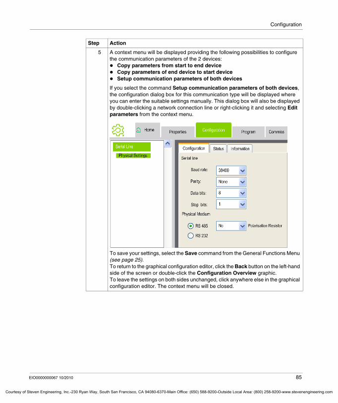
Configuration
Courtesy o
5 A context menu will be displayed providing the following possibilities to configure the communication parameters of the 2 devices:
Copy parameters from start to end deviceCopy parameters of end device to start deviceSetup communication parameters of both devices
If you select the command Setup communication parameters of both devices, the configuration dialog box for this communication type will be displayed where you can enter the suitable settings manually. This dialog box will also be displayed by double-clicking a network connection line or right-clicking it and selecting Edit parameters from the context menu.
To save your settings, select the Save command from the General Functions Menu (see page 25).To return to the graphical configuration editor, click the Back button on the left-hand side of the screen or double-click the Configuration Overview graphic.To leave the settings on both sides unchanged, click anywhere else in the graphical configuration editor. The context menu will be closed.
Step Action
EIO0000000067 10/2010 85
f Steven Engineering, Inc.-230 Ryan Way, South San Francisco, CA 94080-6370-Main Office: (650) 588-9200-Outside Local Area: (800) 258-9200-www.stevenengineering.com
Configuration
Courtesy of St
Color Definitions
The type of network connection is indicated by the color of the connection lines:
Deleting Network Connections
To delete a network connection from the graphical configuration editor, right-click it and select Delete from the context menu, or select the network connection line in the editor and press the DELETE key on your keyboard. If you confirm this action, the network connection will be deleted from the graphical configuration editor, but the configuration parameters of the connected devices will not be changed.
Consistency Checks
SoMachine automatically checks the consistency when creating new network connections. It issues error detection messages as tooltips if it detects any incompatibility.
You can disable this function for individual connections. To achieve this, right-click the network connection line and select the command Disable consistency checks from the context menu. The network connection line will be displayed with a red-striped background to indicate that the consistency check is disabled.
To re-enable the consistency check for a connection line, right-click it and select once again the command Disable consistency checks from the context menu.
Network Connection Line Color Network Connection Type
black Modbus
blue Ethernet
purple CANopen
gray connection to a generic port (no compatibility check performed by SoMachine)
86 EIO0000000067 10/2010
even Engineering, Inc.-230 Ryan Way, South San Francisco, CA 94080-6370-Main Office: (650) 588-9200-Outside Local Area: (800) 258-9200-www.stevenengineering.com
EIO0000000067 10/2010
Courtesy of Steven Engineering, Inc.-230 Ryan Way, South San Francisco, CA 94080-6370-Main Office: (650) 588-9200-Outside Local Ar
6
Device Configuration with Device Type Manager (DTM)
EIO0000000067 10/2010
Device Configuration with Device Type Manager (DTM)
What's in this Chapter?
This chapter contains the following sections:
Section Topic Page
6.1 General Information 88
6.2 Main Use Cases for Configuration 96
6.3 FDT Options 124
6.4 Device Configuration 126
87
ea: (800) 258-9200-www.stevenengineering.com
Device Configuration with Device Type Manager (DTM)
Courtesy of St
6.1 General Information
What's in this Section?
This section contains the following topics:
Topic Page
What is FDT? 89
SoMachine as FDT Container 90
Typical Topologies 91
Devices with Device Type Manager (DTM) 93
FDT Services 95
88 EIO0000000067 10/2010
even Engineering, Inc.-230 Ryan Way, South San Francisco, CA 94080-6370-Main Office: (650) 588-9200-Outside Local Area: (800) 258-9200-www.stevenengineering.com
Device Configuration with Device Type Manager (DTM)
Courtesy o
What is FDT?
Overview
FDT (Field Device Tool) technology standardizes the communication interface between field devices and engineering or asset management tools.
FDT Concept
Since 1998, FDT technology has offered both process and factory manufacturing industries a truly open solution for accessing device intelligence that is supplier, system, and protocol independent.
See the official WEB site: www.fdtgroup.org
You can find below some information coming from FDTGROUP:
FDT enables easy device access and configuration through any host system that provides the interface.
FDT is not a new fieldbus protocol. It can be used with any communication protocol. FDT is vendor independent and established as an open publicly available specification. Field information from processes is required during the entire life cycle of a plant or application.
FDT supports all phases of a plant life cycle: engineeringinstallationcommissioningproductionmaintenance
FDT specifies these standardized software interfaces. They were defined in a general way, so that it is possible to design engineering environments that could manage any device from any manufacturer using an arbitrary protocol as required by end users. The device vendor provides the interfaces for the DTM (Device Type Manager), including communication capabilities to the device itself but also to other DTMs. The Device Type Manager of a device from one vendor is thus able to interact with the Device Type Manager of a device from another vendor. This allows connecting products of different vendors, to have greater flexibility. It is possible to select the device best fitting the demands of the application, independent from vendor or communication protocol.
EIO0000000067 10/2010 89
f Steven Engineering, Inc.-230 Ryan Way, South San Francisco, CA 94080-6370-Main Office: (650) 588-9200-Outside Local Area: (800) 258-9200-www.stevenengineering.com
Device Configuration with Device Type Manager (DTM)
Courtesy of St
SoMachine as FDT Container
Overview
The FDT/DTM, an open-standard, integrates the configuration tools needed to build projects, with a mix of Schneider and Third Party intelligent devices, on heterogeneous networks.
SoMachine is an FDT Container for DTMs.
NOTE: Schneider Electric is not responsible for the correct functioning of non Schneider Electric DTMs under SoMachine.
FDT Concept with SoMachine
The FDT defines the interfaces between device-specific software components (DTMs) and SoMachine. The focus of the current version of FDT is on engineering, commissioning, diagnostics and documentation of fieldbus based control systems.
The device-specific software component is called a DTM (Device Type Manager), which is supplied with the device by the manufacturer. Because the FDT technology used in SoMachine is based on an open standard, SoMachine accepts compliant DTM products from any DTM/device vendor.
NOTE: The DTMs are installed/uninstalled on the PC that runs SoMachine and information about the DTMs is kept in the Windows Registry.
NOTE: The DTM vendor is responsible for the DTM Configuration Online Help which is not part of the SoMachine Online Help.
90 EIO0000000067 10/2010
even Engineering, Inc.-230 Ryan Way, South San Francisco, CA 94080-6370-Main Office: (650) 588-9200-Outside Local Area: (800) 258-9200-www.stevenengineering.com
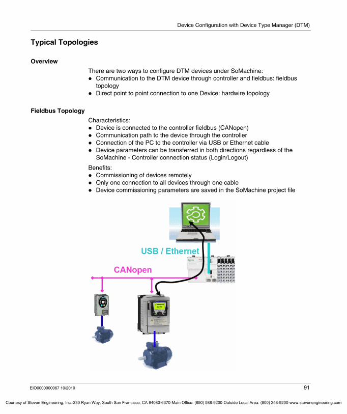
Device Configuration with Device Type Manager (DTM)
Courtesy o
Typical Topologies
Overview
There are two ways to configure DTM devices under SoMachine:Communication to the DTM device through controller and fieldbus: fieldbus topologyDirect point to point connection to one Device: hardwire topology
Fieldbus Topology
Characteristics:Device is connected to the controller fieldbus (CANopen)Communication path to the device through the controllerConnection of the PC to the controller via USB or Ethernet cableDevice parameters can be transferred in both directions regardless of the SoMachine - Controller connection status (Login/Logout)
Benefits:Commissioning of devices remotelyOnly one connection to all devices through one cableDevice commissioning parameters are saved in the SoMachine project file
EIO0000000067 10/2010 91
f Steven Engineering, Inc.-230 Ryan Way, South San Francisco, CA 94080-6370-Main Office: (650) 588-9200-Outside Local Area: (800) 258-9200-www.stevenengineering.com
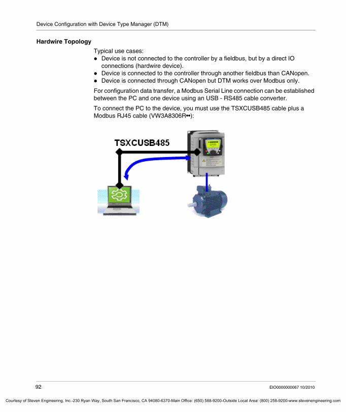
Device Configuration with Device Type Manager (DTM)
Courtesy of St
Hardwire Topology
Typical use cases:Device is not connected to the controller by a fieldbus, but by a direct IO connections (hardwire device). Device is connected to the controller through another fieldbus than CANopen.Device is connected through CANopen but DTM works over Modbus only.
For configuration data transfer, a Modbus Serial Line connection can be established between the PC and one device using an USB - RS485 cable converter.
To connect the PC to the device, you must use the TSXCUSB485 cable plus a Modbus RJ45 cable (VW3A8306R••):
92 EIO0000000067 10/2010
even Engineering, Inc.-230 Ryan Way, South San Francisco, CA 94080-6370-Main Office: (650) 588-9200-Outside Local Area: (800) 258-9200-www.stevenengineering.com
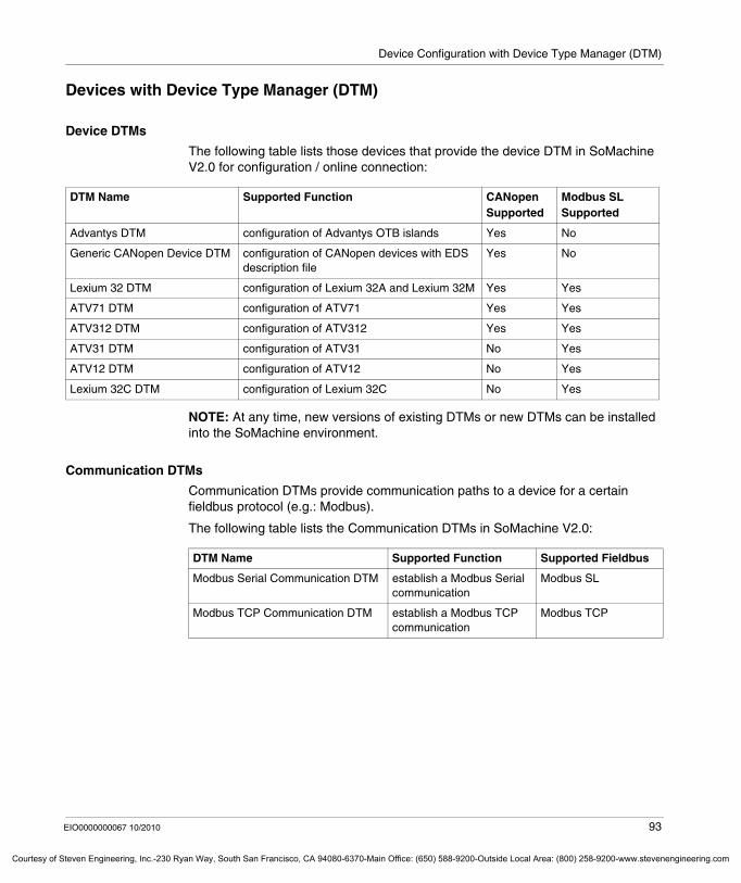
Device Configuration with Device Type Manager (DTM)
Courtesy o
Devices with Device Type Manager (DTM)
Device DTMs
The following table lists those devices that provide the device DTM in SoMachine V2.0 for configuration / online connection:
NOTE: At any time, new versions of existing DTMs or new DTMs can be installed into the SoMachine environment.
Communication DTMs
Communication DTMs provide communication paths to a device for a certain fieldbus protocol (e.g.: Modbus).
The following table lists the Communication DTMs in SoMachine V2.0:
DTM Name Supported Function CANopen Supported
Modbus SL Supported
Advantys DTM configuration of Advantys OTB islands Yes No
Generic CANopen Device DTM configuration of CANopen devices with EDS description file
Yes No
Lexium 32 DTM configuration of Lexium 32A and Lexium 32M Yes Yes
ATV71 DTM configuration of ATV71 Yes Yes
ATV312 DTM configuration of ATV312 Yes Yes
ATV31 DTM configuration of ATV31 No Yes
ATV12 DTM configuration of ATV12 No Yes
Lexium 32C DTM configuration of Lexium 32C No Yes
DTM Name Supported Function Supported Fieldbus
Modbus Serial Communication DTM establish a Modbus Serial communication
Modbus SL
Modbus TCP Communication DTM establish a Modbus TCP communication
Modbus TCP
EIO0000000067 10/2010 93
f Steven Engineering, Inc.-230 Ryan Way, South San Francisco, CA 94080-6370-Main Office: (650) 588-9200-Outside Local Area: (800) 258-9200-www.stevenengineering.com
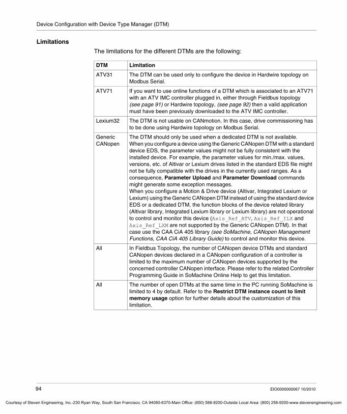
Device Configuration with Device Type Manager (DTM)
Courtesy of St
Limitations
The limitations for the different DTMs are the following:
DTM Limitation
ATV31 The DTM can be used only to configure the device in Hardwire topology on Modbus Serial.
ATV71 If you want to use online functions of a DTM which is associated to an ATV71 with an ATV IMC controller plugged in, either through Fieldbus topology (see page 91) or Hardwire topology, (see page 92) then a valid application must have been previously downloaded to the ATV IMC controller.
Lexium32 The DTM is not usable on CANmotion. In this case, drive commissioning has to be done using Hardwire topology on Modbus Serial.
Generic CANopen
The DTM should only be used when a dedicated DTM is not available.When you configure a device using the Generic CANopen DTM with a standard device EDS, the parameter values might not be fully consistent with the installed device. For example, the parameter values for min./max. values, versions, etc. of Altivar or Lexium drives listed in the standard EDS file might not be fully compatible with the drives in the currently used ranges. As a consequence, Parameter Upload and Parameter Download commands might generate some exception messages.When you configure a Motion & Drive device (Altivar, Integrated Lexium or Lexium) using the Generic CANopen DTM instead of using the standard device EDS or a dedicated DTM, the function blocks of the device related library (Altivar library, Integrated Lexium library or Lexium library) are not operational to control and monitor this device (Axis_Ref_ATV, Axis_Ref_ILX and Axis_Ref_LXM are not supported by the Generic CANopen DTM). In that case use the CAA CiA 405 library (see SoMachine, CANopen Management Functions, CAA CiA 405 Library Guide) to control and monitor this device.
All In Fieldbus Topology, the number of CANopen device DTMs and standard CANopen devices declared in a CANopen configuration of a controller is limited to the maximum number of CANopen devices supported by the concerned controller CANopen interface. Please refer to the related Controller Programming Guide in SoMachine Online Help to get this limitation.
All The number of open DTMs at the same time in the PC running SoMachine is limited to 4 by default. Refer to the Restrict DTM instance count to limit memory usage option for further details about the customization of this limitation.
94 EIO0000000067 10/2010
even Engineering, Inc.-230 Ryan Way, South San Francisco, CA 94080-6370-Main Office: (650) 588-9200-Outside Local Area: (800) 258-9200-www.stevenengineering.com
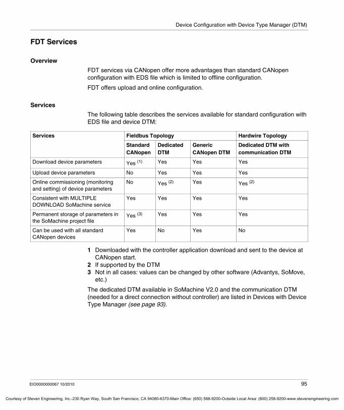
Device Configuration with Device Type Manager (DTM)
Courtesy o
FDT Services
Overview
FDT services via CANopen offer more advantages than standard CANopen configuration with EDS file which is limited to offline configuration.
FDT offers upload and online configuration.
Services
The following table describes the services available for standard configuration with EDS file and device DTM:
1 Downloaded with the controller application download and sent to the device at CANopen start.
2 If supported by the DTM3 Not in all cases: values can be changed by other software (Advantys, SoMove,
etc.)
The dedicated DTM available in SoMachine V2.0 and the communication DTM (needed for a direct connection without controller) are listed in Devices with Device Type Manager (see page 93).
Services Fieldbus Topology Hardwire Topology
Standard CANopen
Dedicated DTM
Generic CANopen DTM
Dedicated DTM with communication DTM
Download device parameters Yes (1) Yes Yes Yes
Upload device parameters No Yes Yes Yes
Online commissioning (monitoring and setting) of device parameters
No Yes (2) Yes Yes (2)
Consistent with MULTIPLE DOWNLOAD SoMachine service
Yes Yes Yes Yes
Permanent storage of parameters in the SoMachine project file
Yes (3) Yes Yes Yes
Can be used with all standard CANopen devices
Yes No Yes No
EIO0000000067 10/2010 95
f Steven Engineering, Inc.-230 Ryan Way, South San Francisco, CA 94080-6370-Main Office: (650) 588-9200-Outside Local Area: (800) 258-9200-www.stevenengineering.com
Device Configuration with Device Type Manager (DTM)
Courtesy of St
6.2 Main Use Cases for Configuration
What's in this Section?
This section contains the following topics:
Topic Page
Device Type Manager (DTM) Installation 97
Configuration Offline with the Dedicated DTM 101
Configuration Online with the Dedicated DTM 105
Configuration with Generic DTM 113
Hardwire Topology 117
96 EIO0000000067 10/2010
even Engineering, Inc.-230 Ryan Way, South San Francisco, CA 94080-6370-Main Office: (650) 588-9200-Outside Local Area: (800) 258-9200-www.stevenengineering.com
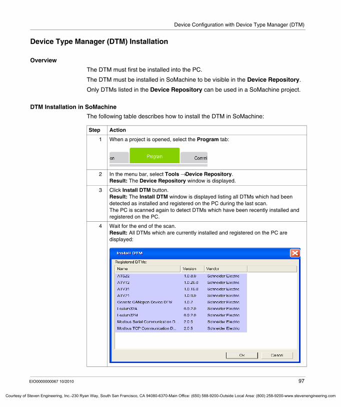
Device Configuration with Device Type Manager (DTM)
Courtesy o
Device Type Manager (DTM) Installation
Overview
The DTM must first be installed into the PC.
The DTM must be installed in SoMachine to be visible in the Device Repository.
Only DTMs listed in the Device Repository can be used in a SoMachine project.
DTM Installation in SoMachine
The following table describes how to install the DTM in SoMachine:
Step Action
1 When a project is opened, select the Program tab:
2 In the menu bar, select Tools → Device Repository.Result: The Device Repository window is displayed.
3 Click Install DTM button.Result: The Install DTM window is displayed listing all DTMs which had been detected as installed and registered on the PC during the last scan.The PC is scanned again to detect DTMs which have been recently installed and registered on the PC.
4 Wait for the end of the scan.Result: All DTMs which are currently installed and registered on the PC are displayed:
EIO0000000067 10/2010 97
f Steven Engineering, Inc.-230 Ryan Way, South San Francisco, CA 94080-6370-Main Office: (650) 588-9200-Outside Local Area: (800) 258-9200-www.stevenengineering.com
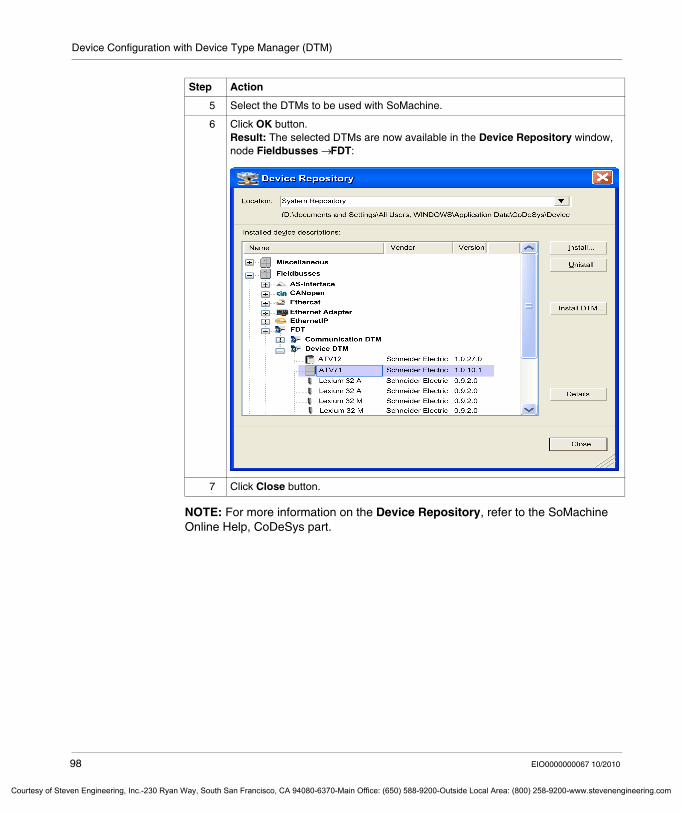
Device Configuration with Device Type Manager (DTM)
Courtesy of St
NOTE: For more information on the Device Repository, refer to the SoMachine Online Help, CoDeSys part.
5 Select the DTMs to be used with SoMachine.
6 Click OK button.Result: The selected DTMs are now available in the Device Repository window, node Fieldbusses → FDT:
7 Click Close button.
Step Action
98 EIO0000000067 10/2010
even Engineering, Inc.-230 Ryan Way, South San Francisco, CA 94080-6370-Main Office: (650) 588-9200-Outside Local Area: (800) 258-9200-www.stevenengineering.com
Device Configuration with Device Type Manager (DTM)
Courtesy o
Add a CANopen Device DTM to the Device Tree
Before you can add a CANopen device DTM to the Device tree, you have to make sure that a CANopen manager has been inserted in the Device tree. For more details, refer to the SoMachine Online Help.
The following table describes how to add a DTM device in the Device tree:
Step Action
1 Select the Program tab:
2 Right click on the CANopen manager, select Add Device.Result: The Add Device window is displayed.
EIO0000000067 10/2010 99
f Steven Engineering, Inc.-230 Ryan Way, South San Francisco, CA 94080-6370-Main Office: (650) 588-9200-Outside Local Area: (800) 258-9200-www.stevenengineering.com
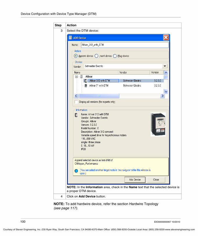
Device Configuration with Device Type Manager (DTM)
Courtesy of St
NOTE: To add hardwire device, refer the section Hardwire Topology (see page 117).
3 Select the DTM device:
NOTE: In the Information area, check in the Name text that the selected device is a proper DTM device.
4 Click on Add Device button.
Step Action
100 EIO0000000067 10/2010
even Engineering, Inc.-230 Ryan Way, South San Francisco, CA 94080-6370-Main Office: (650) 588-9200-Outside Local Area: (800) 258-9200-www.stevenengineering.com
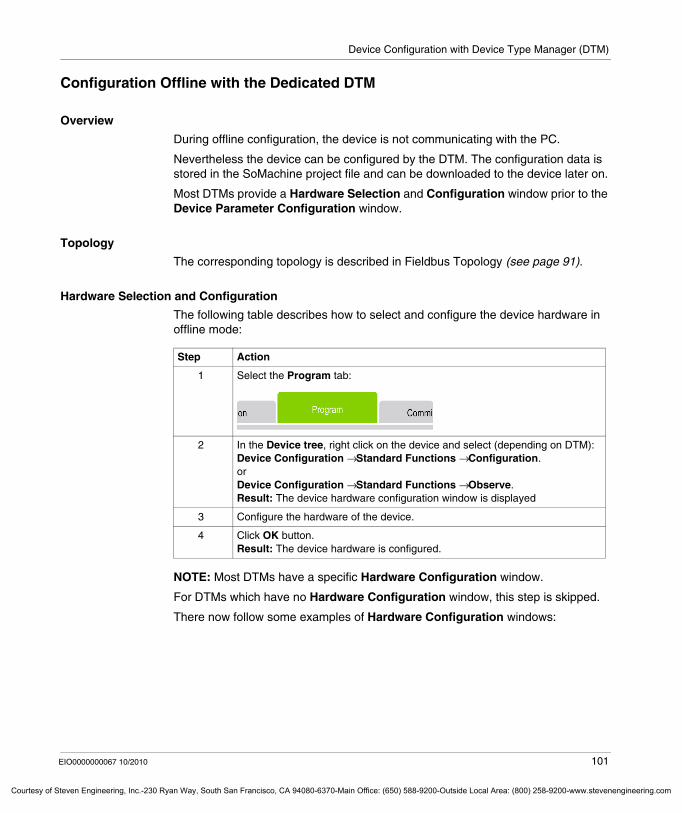
Device Configuration with Device Type Manager (DTM)
Courtesy o
Configuration Offline with the Dedicated DTM
Overview
During offline configuration, the device is not communicating with the PC.
Nevertheless the device can be configured by the DTM. The configuration data is stored in the SoMachine project file and can be downloaded to the device later on.
Most DTMs provide a Hardware Selection and Configuration window prior to the Device Parameter Configuration window.
Topology
The corresponding topology is described in Fieldbus Topology (see page 91).
Hardware Selection and Configuration
The following table describes how to select and configure the device hardware in offline mode:
NOTE: Most DTMs have a specific Hardware Configuration window.
For DTMs which have no Hardware Configuration window, this step is skipped.
There now follow some examples of Hardware Configuration windows:
Step Action
1 Select the Program tab:
2 In the Device tree, right click on the device and select (depending on DTM):Device Configuration → Standard Functions → Configuration.orDevice Configuration → Standard Functions → Observe.Result: The device hardware configuration window is displayed
3 Configure the hardware of the device.
4 Click OK button.Result: The device hardware is configured.
EIO0000000067 10/2010 101
f Steven Engineering, Inc.-230 Ryan Way, South San Francisco, CA 94080-6370-Main Office: (650) 588-9200-Outside Local Area: (800) 258-9200-www.stevenengineering.com
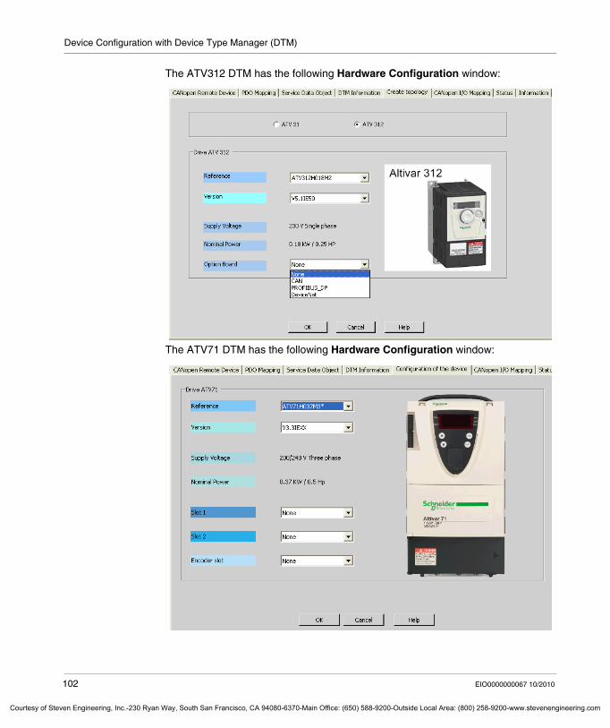
Device Configuration with Device Type Manager (DTM)
Courtesy of St
The ATV312 DTM has the following Hardware Configuration window:
The ATV71 DTM has the following Hardware Configuration window:
102 EIO0000000067 10/2010
even Engineering, Inc.-230 Ryan Way, South San Francisco, CA 94080-6370-Main Office: (650) 588-9200-Outside Local Area: (800) 258-9200-www.stevenengineering.com
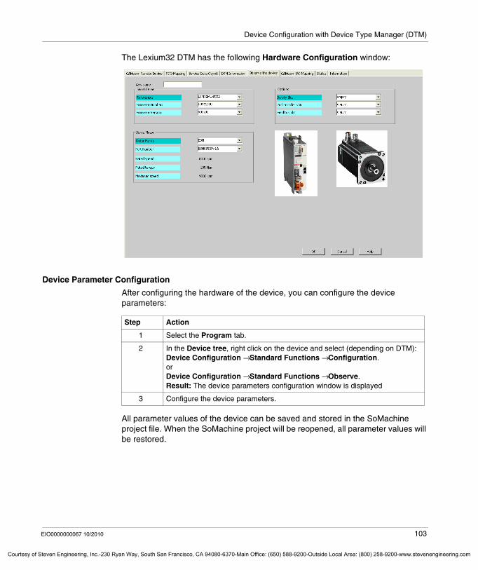
Device Configuration with Device Type Manager (DTM)
Courtesy o
The Lexium32 DTM has the following Hardware Configuration window:
Device Parameter Configuration
After configuring the hardware of the device, you can configure the device parameters:
All parameter values of the device can be saved and stored in the SoMachine project file. When the SoMachine project will be reopened, all parameter values will be restored.
Step Action
1 Select the Program tab.
2 In the Device tree, right click on the device and select (depending on DTM):Device Configuration → Standard Functions → Configuration.orDevice Configuration → Standard Functions → Observe.Result: The device parameters configuration window is displayed
3 Configure the device parameters.
EIO0000000067 10/2010 103
f Steven Engineering, Inc.-230 Ryan Way, South San Francisco, CA 94080-6370-Main Office: (650) 588-9200-Outside Local Area: (800) 258-9200-www.stevenengineering.com
Device Configuration with Device Type Manager (DTM)
Courtesy of St
For more information about DTM configuration, see the specific DTM documentation of the selected device:
NOTE: The configuration in SoMachine must be consistent with the physical device connected.
If some discrepancy in configuration exists (for example, the reference number of the connected device is not the same as the pre-defined device declared in the configuration), the services Parameter upload, Parameter download and Switch to Synchronize mode will be rejected by the device.
If this happens, you have to delete the device in SoMachine and add a new one that is fully consistent with the configuration of the physical remote device.
Step Action
1 Select the Program tab.
2 In the Device tree, right click on the device and select Device Configuration → Documentation.Result: The DTM documentation is displayed.
104 EIO0000000067 10/2010
even Engineering, Inc.-230 Ryan Way, South San Francisco, CA 94080-6370-Main Office: (650) 588-9200-Outside Local Area: (800) 258-9200-www.stevenengineering.com
Device Configuration with Device Type Manager (DTM)
Courtesy o
Configuration Online with the Dedicated DTM
Overview
When the device is physically connected to the controller, SoMachine allows to upload/download parameters from/to the device and to adjust these parameters.
Before downloading parameters to a device, be aware that a download of communication parameters with wrong values might cause unexpected operation in the device, especially if it is already in operating mode.
If you want to upload/download parameters to the device, you do not need to log into the controller but a user application with CANopen configuration must have been previously downloaded in the controller.
NOTE: It is a good diagnostic practice to log into the controller in order to check the status of the device in the Device tree (green icon: device connected and accessible).
WARNINGLOSS OF COMMUNICATION
Do not download parameters to a device when:the node address configured in the device is not consistent with the node address parameter configured in device DTM.the baud rate configured in the device is not consistent with the baud rate parameter configured in device DTM.
Failure to follow these instructions can result in death, serious injury, or equipment damage.
WARNINGUNINTENDED EQUIPMENT OPERATION
Thoroughly read and understand the device manual for the characteristics and properties of the device before attempting to modify them.
Failure to follow these instructions can result in death, serious injury, or equipment damage.
EIO0000000067 10/2010 105
f Steven Engineering, Inc.-230 Ryan Way, South San Francisco, CA 94080-6370-Main Office: (650) 588-9200-Outside Local Area: (800) 258-9200-www.stevenengineering.com
Device Configuration with Device Type Manager (DTM)
Courtesy of St
Limitation of the Operation in Online Mode
During normal operation of SoMachine, it is possible that a user application runs in the controller (RUNNING state) and modifies device parameters, while at the same time, the DTM also modifies online the devices parameters. In this case, 2 active communication channels in parallel have access to the device to modify the behavior.
The exchange of device parameters by the DTM (using Parameter Download, Parameter Upload commands or Synchronized mode) while the controller application is running in parallel could lead to unintended consequences.
Technical note:
CANopen device DTM exchanges data with the remote device using SDO services. In many Schneider CANopen devices, only one SDO channel is supported. This limitation leads to an increase of the SDO exchange time between the controller and the device (see the following note).
NOTE: A device DTM can be switched to Online when the controller is in RUNNING or in STOPPED state.
In the case that the controller can be in RUNNING state (e.g. to write calculated data to the device) and at the same time the DTM is in Online (e.g. to synchronize data), the bandwidth of the SDO channel is divided into 2 different sub-channels:
Sub-channel 1: SDO service sent by the controller program application in real time for specific adjustment.Sub-channel 2: SDO service sent by the DTM in Online mode.
Because there is no priority management between these 2 sub-channels, all SDO messages are interlaced.
If both sub-channels are communicating at the same time with the remote device, the CANopen bandwidth limitation can introduce some delays in the SDO sent by the program application.
WARNINGUNINTENDED EQUIPMENT OPERATION
Do not change device parameters by DTM in parallel to device parameter modifications made by the RUNNING application.
Failure to follow these instructions can result in death, serious injury, or equipment damage.
106 EIO0000000067 10/2010
even Engineering, Inc.-230 Ryan Way, South San Francisco, CA 94080-6370-Main Office: (650) 588-9200-Outside Local Area: (800) 258-9200-www.stevenengineering.com
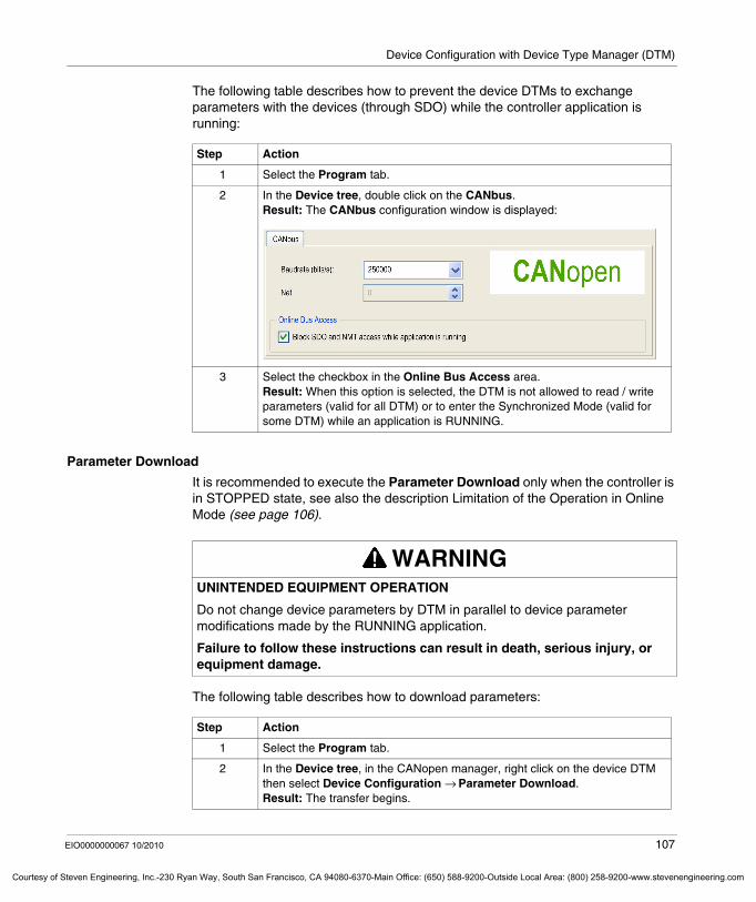
Device Configuration with Device Type Manager (DTM)
Courtesy o
The following table describes how to prevent the device DTMs to exchange parameters with the devices (through SDO) while the controller application is running:
Parameter Download
It is recommended to execute the Parameter Download only when the controller is in STOPPED state, see also the description Limitation of the Operation in Online Mode (see page 106).
The following table describes how to download parameters:
Step Action
1 Select the Program tab.
2 In the Device tree, double click on the CANbus.Result: The CANbus configuration window is displayed:
3 Select the checkbox in the Online Bus Access area.Result: When this option is selected, the DTM is not allowed to read / write parameters (valid for all DTM) or to enter the Synchronized Mode (valid for some DTM) while an application is RUNNING.
WARNINGUNINTENDED EQUIPMENT OPERATION
Do not change device parameters by DTM in parallel to device parameter modifications made by the RUNNING application.
Failure to follow these instructions can result in death, serious injury, or equipment damage.
Step Action
1 Select the Program tab.
2 In the Device tree, in the CANopen manager, right click on the device DTM then select Device Configuration → Parameter Download.Result: The transfer begins.
EIO0000000067 10/2010 107
f Steven Engineering, Inc.-230 Ryan Way, South San Francisco, CA 94080-6370-Main Office: (650) 588-9200-Outside Local Area: (800) 258-9200-www.stevenengineering.com
Device Configuration with Device Type Manager (DTM)
Courtesy of St
Parameters Download to all Attached DTMs
It is recommended to execute the Parameter Download to all Attached DTMs only when the controller is in STOPPED state, see also the description Limitation of the Operation in Online Mode (see page 106).
The aim of this function is to download all device DTM parameters to all the attached devices. By this, you have not to repeat parameter download command for all the devices. It provides consistency of the data in the SoMachine project and the data in the devices.
The following table describes how to download device parameter DTM to all attached devices:
3 At the end of the transfer, a message is displayed.
4 All parameters are downloaded to the device.
Step Action
WARNINGUNINTENDED EQUIPMENT OPERATION
Do not change device parameters by DTM in parallel to device parameter modifications made by the RUNNING application.
Failure to follow these instructions can result in death, serious injury, or equipment damage.
Step Action
1 Select the Program tab.
2 In the Device tree, in the CANopen manager, right click on the DTM then select Device Configuration → Parameter download to all attached DTMs.Result: The transfer begins.
3 At the end of the transfer, a message is displayed.
4 The parameters of all DTM are downloaded to all the attached devices.
108 EIO0000000067 10/2010
even Engineering, Inc.-230 Ryan Way, South San Francisco, CA 94080-6370-Main Office: (650) 588-9200-Outside Local Area: (800) 258-9200-www.stevenengineering.com
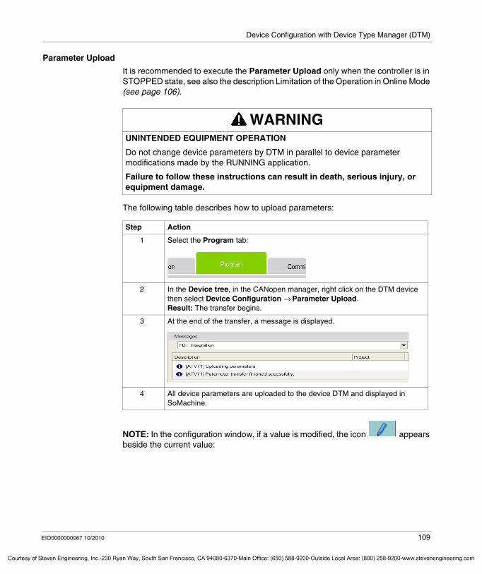
Device Configuration with Device Type Manager (DTM)
Courtesy o
Parameter Upload
It is recommended to execute the Parameter Upload only when the controller is in STOPPED state, see also the description Limitation of the Operation in Online Mode (see page 106).
The following table describes how to upload parameters:
NOTE: In the configuration window, if a value is modified, the icon appears beside the current value:
WARNINGUNINTENDED EQUIPMENT OPERATION
Do not change device parameters by DTM in parallel to device parameter modifications made by the RUNNING application.
Failure to follow these instructions can result in death, serious injury, or equipment damage.
Step Action
1 Select the Program tab:
2 In the Device tree, in the CANopen manager, right click on the DTM device then select Device Configuration → Parameter Upload.Result: The transfer begins.
3 At the end of the transfer, a message is displayed.
4 All device parameters are uploaded to the device DTM and displayed in SoMachine.
EIO0000000067 10/2010 109
f Steven Engineering, Inc.-230 Ryan Way, South San Francisco, CA 94080-6370-Main Office: (650) 588-9200-Outside Local Area: (800) 258-9200-www.stevenengineering.com
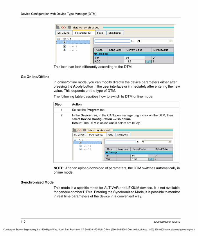
Device Configuration with Device Type Manager (DTM)
Courtesy of St
This icon can look differently according to the DTM.
Go Online/Offline
In online/offline mode, you can modify directly the device parameters either after pressing the Apply button in the user interface or immediately after entering the new value. This depends on the type of DTM.
The following table describes how to switch to DTM online mode:
NOTE: After an upload/download of parameters, the DTM switches automatically in online mode.
Synchronized Mode
This mode is a specific mode for ALTIVAR and LEXIUM devices. It is not available for generic or other DTMs. Entering the Synchronized Mode, it is possible to monitor in real time parameters of the device in a convenient way.
Step Action
1 Select the Program tab.
2 In the Device tree, in the CANopen manager, right click on the DTM, then select Device Configuration → Go online.Result: The DTM is online (main colors are blue):
110 EIO0000000067 10/2010
even Engineering, Inc.-230 Ryan Way, South San Francisco, CA 94080-6370-Main Office: (650) 588-9200-Outside Local Area: (800) 258-9200-www.stevenengineering.com
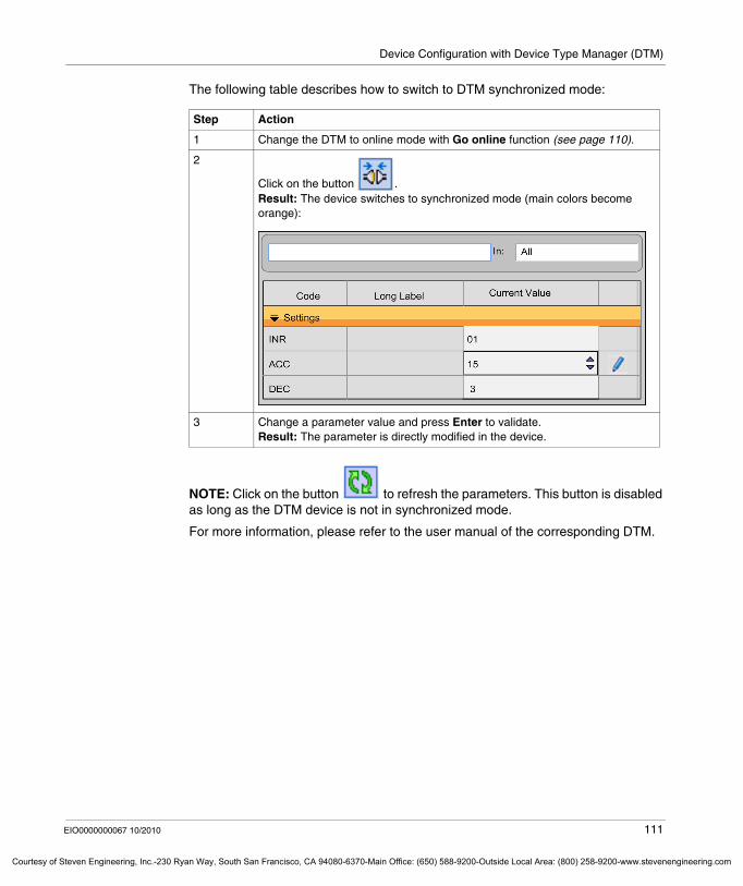
Device Configuration with Device Type Manager (DTM)
Courtesy o
The following table describes how to switch to DTM synchronized mode:
NOTE: Click on the button to refresh the parameters. This button is disabled as long as the DTM device is not in synchronized mode.
For more information, please refer to the user manual of the corresponding DTM.
Step Action
1 Change the DTM to online mode with Go online function (see page 110).
2
Click on the button .Result: The device switches to synchronized mode (main colors become orange):
3 Change a parameter value and press Enter to validate.Result: The parameter is directly modified in the device.
EIO0000000067 10/2010 111
f Steven Engineering, Inc.-230 Ryan Way, South San Francisco, CA 94080-6370-Main Office: (650) 588-9200-Outside Local Area: (800) 258-9200-www.stevenengineering.com
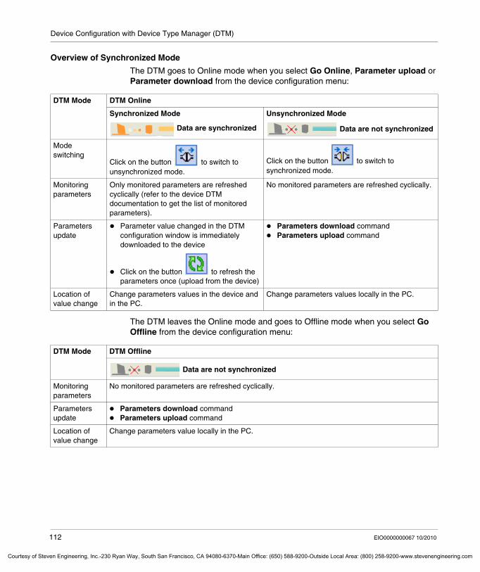
Device Configuration with Device Type Manager (DTM)
Courtesy of St
Overview of Synchronized Mode
The DTM goes to Online mode when you select Go Online, Parameter upload or Parameter download from the device configuration menu:
The DTM leaves the Online mode and goes to Offline mode when you select Go Offline from the device configuration menu:
DTM Mode DTM Online
Synchronized Mode
Data are synchronized
Unsynchronized Mode
Data are not synchronized
Mode switching
Click on the button to switch to unsynchronized mode.
Click on the button to switch to synchronized mode.
Monitoring parameters
Only monitored parameters are refreshed cyclically (refer to the device DTM documentation to get the list of monitored parameters).
No monitored parameters are refreshed cyclically.
Parameters update
Parameter value changed in the DTM configuration window is immediately downloaded to the device
Click on the button to refresh the parameters once (upload from the device)
Parameters download commandParameters upload command
Location of value change
Change parameters values in the device and in the PC.
Change parameters values locally in the PC.
DTM Mode DTM Offline
Data are not synchronized
Monitoring parameters
No monitored parameters are refreshed cyclically.
Parameters update
Parameters download commandParameters upload command
Location of value change
Change parameters value locally in the PC.
112 EIO0000000067 10/2010
even Engineering, Inc.-230 Ryan Way, South San Francisco, CA 94080-6370-Main Office: (650) 588-9200-Outside Local Area: (800) 258-9200-www.stevenengineering.com
Device Configuration with Device Type Manager (DTM)
Courtesy o
Configuration with Generic DTM
Overview
Usually, a DTM is dedicated to one specific device type or a device family.
In SoMachine the Generic CANopen Device DTM supports all the CANopen devices which do not have a dedicated DTM, but an EDS description file.
The Generic CANopen Device DTM functionalities and the GUI (Graphical User Interface) are implemented in a universal way. By this, the DTM can be used with any device which supports CANopen.
The Generic CANopen Device DTM converts device descriptions in EDS format into DDXML format (Schneider Electric internal device description). The DDXML is interpreted to visualize all parameters of the EDS in a GUI and to create means for user interaction to manage them accordingly.
Each EDS file with the description of one device, which is copied to a certain location on the PC (please refer to the user manual of the Generic CANopen Device DTM) is represented in the Device Repository as one Device DTM which can be inserted in the Device tree of SoMachine.
The Generic CANopen Device DTM provides the following features:Upload/DownloadDisplay Identification information of a deviceOffline parameterization of CANopen parametersOffline parameterization of device specific parametersOnline monitoring of parametersOnline setting of parametersCompare of offline configuration with the configuration on the deviceView the device description files (EDS and DDXML) of selected device
EIO0000000067 10/2010 113
f Steven Engineering, Inc.-230 Ryan Way, South San Francisco, CA 94080-6370-Main Office: (650) 588-9200-Outside Local Area: (800) 258-9200-www.stevenengineering.com
Device Configuration with Device Type Manager (DTM)
Courtesy of St
Create a New Generic CANopen Device DTM
The following table describes how to create and add a new device DTM from a standard CANopen EDS to the device repository:
NOTE: If the DDXML file is not created, then there is a problem with the EDS file. Check the detected error message to find out the problem with the EDS file. Refer to the chapter “Handling of invalid EDS files” in the user manual of the Generic CANopen device DTM.
If several EDS files are copied into the EDS directory, several new device DTMs will be created.
After the DDXML is created successfully, a device type is added in the device repository for the given EDS file. The device type created by the Generic CANopen Device DTM in the repository is represented with the Product Name taken from the EDS file. The corresponding DDXML file is also displayed in brackets in the repository next to the device type name.
NOTE: Every time a new EDS file is copied to the mentioned folder, an Install DTM action has to be repeated with selecting the Generic DTM in the list of available DTMs.
Step Action
1 Open the folder at the location Start Windows menu → Program → Schneider Electric → Generic CANopen Device DTM → EDS.
2 Copy in this folder the EDS file for which the device DTM has to be created.
3 Install the Generic CANopen Device DTM as explained in DTM Installation (see page 97).Result: The EDS file is converted into DDXML format and stored under ... → Schneider Electric → Generic CANopen Device DTM → DDXML with the same name.
114 EIO0000000067 10/2010
even Engineering, Inc.-230 Ryan Way, South San Francisco, CA 94080-6370-Main Office: (650) 588-9200-Outside Local Area: (800) 258-9200-www.stevenengineering.com
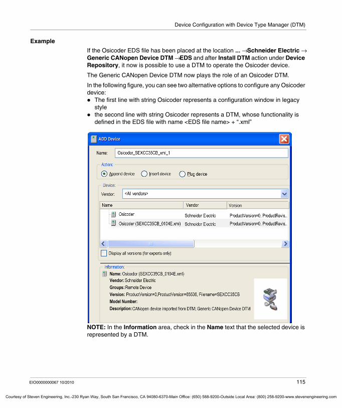
Device Configuration with Device Type Manager (DTM)
Courtesy o
Example
If the Osicoder EDS file has been placed at the location ... → Schneider Electric → Generic CANopen Device DTM → EDS and after Install DTM action under Device Repository, it now is possible to use a DTM to operate the Osicoder device.
The Generic CANopen Device DTM now plays the role of an Osicoder DTM.
In the following figure, you can see two alternative options to configure any Osicoder device:
The first line with string Osicoder represents a configuration window in legacy stylethe second line with string Osicoder represents a DTM, whose functionality is defined in the EDS file with name <EDS file name> + “.xml”
NOTE: In the Information area, check in the Name text that the selected device is represented by a DTM.
EIO0000000067 10/2010 115
f Steven Engineering, Inc.-230 Ryan Way, South San Francisco, CA 94080-6370-Main Office: (650) 588-9200-Outside Local Area: (800) 258-9200-www.stevenengineering.com
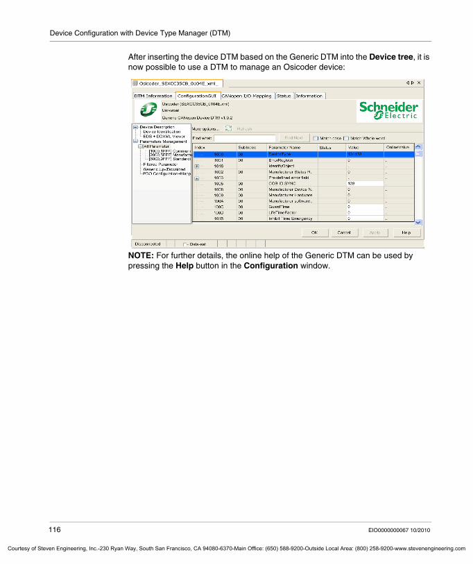
Device Configuration with Device Type Manager (DTM)
Courtesy of St
After inserting the device DTM based on the Generic DTM into the Device tree, it is now possible to use a DTM to manage an Osicoder device:
NOTE: For further details, the online help of the Generic DTM can be used by pressing the Help button in the Configuration window.
116 EIO0000000067 10/2010
even Engineering, Inc.-230 Ryan Way, South San Francisco, CA 94080-6370-Main Office: (650) 588-9200-Outside Local Area: (800) 258-9200-www.stevenengineering.com
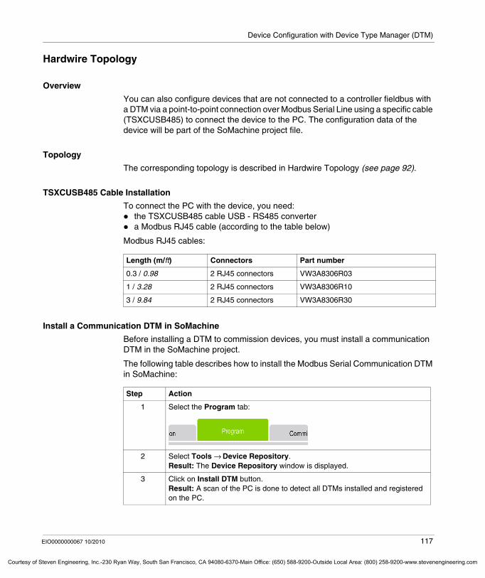
Device Configuration with Device Type Manager (DTM)
Courtesy o
Hardwire Topology
Overview
You can also configure devices that are not connected to a controller fieldbus with a DTM via a point-to-point connection over Modbus Serial Line using a specific cable (TSXCUSB485) to connect the device to the PC. The configuration data of the device will be part of the SoMachine project file.
Topology
The corresponding topology is described in Hardwire Topology (see page 92).
TSXCUSB485 Cable Installation
To connect the PC with the device, you need:the TSXCUSB485 cable USB - RS485 convertera Modbus RJ45 cable (according to the table below)
Modbus RJ45 cables:
Install a Communication DTM in SoMachine
Before installing a DTM to commission devices, you must install a communication DTM in the SoMachine project.
The following table describes how to install the Modbus Serial Communication DTM in SoMachine:
Length (m/ft) Connectors Part number
0.3 / 0.98 2 RJ45 connectors VW3A8306R03
1 / 3.28 2 RJ45 connectors VW3A8306R10
3 / 9.84 2 RJ45 connectors VW3A8306R30
Step Action
1 Select the Program tab:
2 Select Tools → Device Repository.Result: The Device Repository window is displayed.
3 Click on Install DTM button.Result: A scan of the PC is done to detect all DTMs installed and registered on the PC.
EIO0000000067 10/2010 117
f Steven Engineering, Inc.-230 Ryan Way, South San Francisco, CA 94080-6370-Main Office: (650) 588-9200-Outside Local Area: (800) 258-9200-www.stevenengineering.com
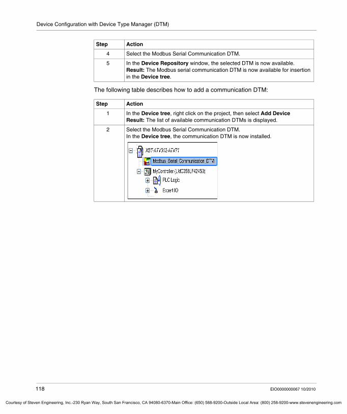
Device Configuration with Device Type Manager (DTM)
Courtesy of St
The following table describes how to add a communication DTM:
4 Select the Modbus Serial Communication DTM.
5 In the Device Repository window, the selected DTM is now available.Result: The Modbus serial communication DTM is now available for insertion in the Device tree.
Step Action
1 In the Device tree, right click on the project, then select Add DeviceResult: The list of available communication DTMs is displayed.
2 Select the Modbus Serial Communication DTM.In the Device tree, the communication DTM is now installed.
Step Action
118 EIO0000000067 10/2010
even Engineering, Inc.-230 Ryan Way, South San Francisco, CA 94080-6370-Main Office: (650) 588-9200-Outside Local Area: (800) 258-9200-www.stevenengineering.com
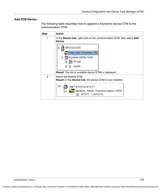
Device Configuration with Device Type Manager (DTM)
Courtesy o
Add DTM Device
The following table describes how to append a (hardwire) device DTM to the communication DTM:
Step Action
1 In the Device tree, right click on the communication DTM, then select Add Device.
Result: The list of available device DTMs is displayed.
2 Select the desired DTM.Result: In the Device tree, the device DTM is now installed:
EIO0000000067 10/2010 119
f Steven Engineering, Inc.-230 Ryan Way, South San Francisco, CA 94080-6370-Main Office: (650) 588-9200-Outside Local Area: (800) 258-9200-www.stevenengineering.com
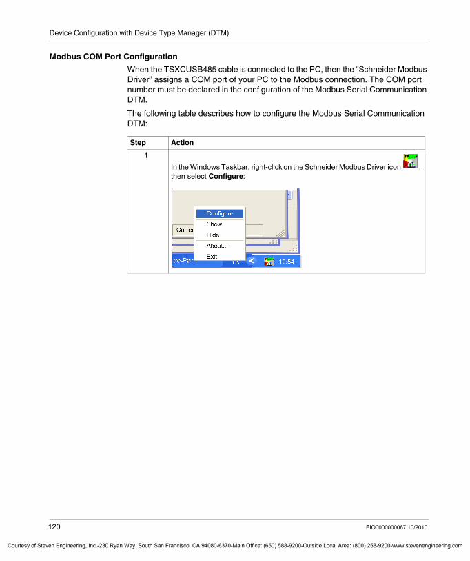
Device Configuration with Device Type Manager (DTM)
Courtesy of St
Modbus COM Port Configuration
When the TSXCUSB485 cable is connected to the PC, then the “Schneider Modbus Driver” assigns a COM port of your PC to the Modbus connection. The COM port number must be declared in the configuration of the Modbus Serial Communication DTM.
The following table describes how to configure the Modbus Serial Communication DTM:
Step Action
1
In the Windows Taskbar, right-click on the Schneider Modbus Driver icon , then select Configure:
120 EIO0000000067 10/2010
even Engineering, Inc.-230 Ryan Way, South San Francisco, CA 94080-6370-Main Office: (650) 588-9200-Outside Local Area: (800) 258-9200-www.stevenengineering.com
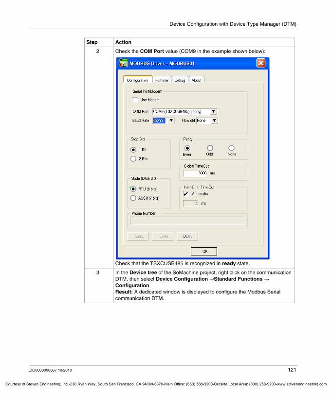
Device Configuration with Device Type Manager (DTM)
Courtesy o
2 Check the COM Port value (COM9 in the example shown below):
Check that the TSXCUSB485 is recognized in ready state.
3 In the Device tree of the SoMachine project, right click on the communication DTM, then select Device Configuration → Standard Functions → Configuration.Result: A dedicated window is displayed to configure the Modbus Serial communication DTM.
Step Action
EIO0000000067 10/2010 121
f Steven Engineering, Inc.-230 Ryan Way, South San Francisco, CA 94080-6370-Main Office: (650) 588-9200-Outside Local Area: (800) 258-9200-www.stevenengineering.com
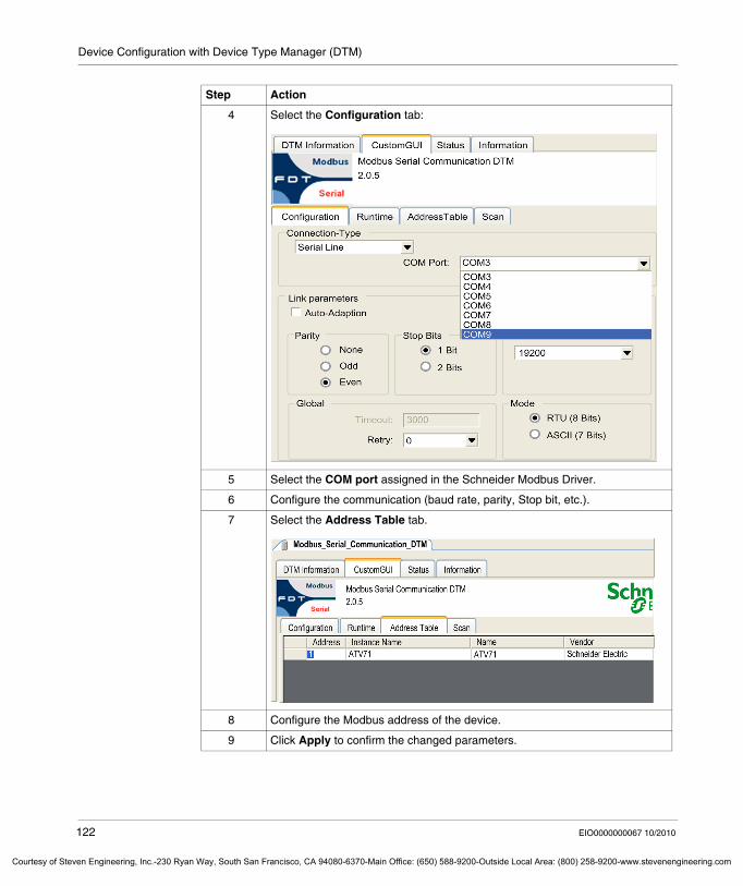
Device Configuration with Device Type Manager (DTM)
Courtesy of St
4 Select the Configuration tab:
5 Select the COM port assigned in the Schneider Modbus Driver.
6 Configure the communication (baud rate, parity, Stop bit, etc.).
7 Select the Address Table tab.
8 Configure the Modbus address of the device.
9 Click Apply to confirm the changed parameters.
Step Action
122 EIO0000000067 10/2010
even Engineering, Inc.-230 Ryan Way, South San Francisco, CA 94080-6370-Main Office: (650) 588-9200-Outside Local Area: (800) 258-9200-www.stevenengineering.com

Device Configuration with Device Type Manager (DTM)
Courtesy o
After configuration of the Modbus Serial Communication DTM, all online services of the attached device DTM are available to start the configuration/commissioning of the device. You can now right click on the device in the Device tree and change/upload/download device parameters.
WARNINGLOSS OF COMMUNICATION
Be sure that the device parameters you intend to download are consistent with those configured for your device, Modbus network, and application.
Failure to follow these instructions can result in death, serious injury, or equipment damage.
EIO0000000067 10/2010 123
f Steven Engineering, Inc.-230 Ryan Way, South San Francisco, CA 94080-6370-Main Office: (650) 588-9200-Outside Local Area: (800) 258-9200-www.stevenengineering.com
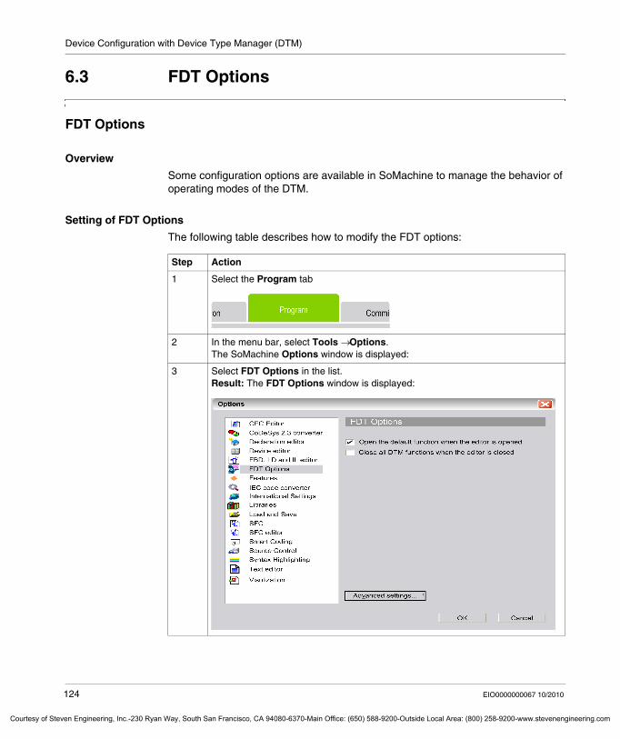
Device Configuration with Device Type Manager (DTM)
Courtesy of St
6.3 FDT Options
FDT Options
Overview
Some configuration options are available in SoMachine to manage the behavior of operating modes of the DTM.
Setting of FDT Options
The following table describes how to modify the FDT options:
Step Action
1 Select the Program tab
2 In the menu bar, select Tools → Options.The SoMachine Options window is displayed:
3 Select FDT Options in the list.Result: The FDT Options window is displayed:
124 EIO0000000067 10/2010
even Engineering, Inc.-230 Ryan Way, South San Francisco, CA 94080-6370-Main Office: (650) 588-9200-Outside Local Area: (800) 258-9200-www.stevenengineering.com
Device Configuration with Device Type Manager (DTM)
Courtesy o
The following table describes the FDT Options:
Advanced Settings
The following table describes the advanced settings of FDT Options:
Option Description
Open the default DTM function when the editor is opened
By double-clicking on the device in the Device treeIf checked: the DTM configuration tab is opened. If unchecked: only SoMachine standard tabs are opened.
Close all DTM functions when the editor is closed
If checked: Close DTM when the SoMachine device editor is closed.It is useful for special DTMs that have not OK or Cancel buttons.
Advanced settings Opens the second FDT Options window for advanced settings.
Option Description
User management according to FDT specification
MUST be kept unchecked. This function is not supported.
Check for change DTM parameters before application login
If selected, an automatic parameter download to those devices is performed before Login if parameters have been changed since the last download. This is useful to keep consistency, but it can result in longer execution time for Login (depends on DTM).
Set DTMs offline after application logout
If selected, all DTMs are switched to offline mode after logout from controller.
Restrict DTM instance count to limit memory usage
If selected (by default), limits the number of DTM instances open at a time on the PC to the Maximum number of DTM instances parameter value (default value is 4, range from 1...10).If not selected, the number of open DTM instances is not limited.NOTE: The option setting will only be active after closing the current project.
NOTE: This option is used to reduce the consumption of PC memory and to avoid the decrease of PC performance. Refer to the Check DTM instances command for further information on currently open DTM instances checking and disposal.
Create temporary device description files when updating the catalog
When the Install DTM... button in the Device Repository window is executed, a device description file is created for every device supported by a DTM.The file is available in a temporary folder and is deleted during SoMachine closing.These device description files are dedicated to developers who want to use the device description files as template for creating their own device description.
Verbose Mode Can be used by DTM developers for trouble shooting.
Show Popups for errors reported by a DTM
If selected, Pop-up messages are generated for detected error messages of DTMs. If not selected, these messages are only shown in the message window of SoMachine.Pop-ups always need to be confirmed by the user. This can slow down operation (eg: for communication errors, if a device is not responding, a number of pop-up messages can occur).
EIO0000000067 10/2010 125
f Steven Engineering, Inc.-230 Ryan Way, South San Francisco, CA 94080-6370-Main Office: (650) 588-9200-Outside Local Area: (800) 258-9200-www.stevenengineering.com
Device Configuration with Device Type Manager (DTM)
Courtesy of St
6.4 Device Configuration
Device Configuration
Overview
The CANopen manager is an obligatory node below the CAN bus node in a CAN bus configuration. Below the CANopen manager you can add one or more CAN bus devices to the device tree.
The CANopen manager and some CAN bus devices provide dialogs or functions for configuration and maintenance of the devices.
Those dialogs or functions are available in the Device Configuration submenu which is displayed by right-clicking the device node or the CANopen manager node.
The availability of dialogs or functions depends on the kind of device and the state of the device. If a dialog or function is currently not available, then the menu item appears dimmed.
NOTE: The CANopen manager supports only the menu items Import DTM and Parameter download to all attached DTMs.... Both menu items are not supported by any other CAN bus device
126 EIO0000000067 10/2010
even Engineering, Inc.-230 Ryan Way, South San Francisco, CA 94080-6370-Main Office: (650) 588-9200-Outside Local Area: (800) 258-9200-www.stevenengineering.com
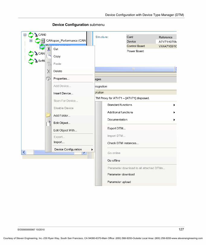
Device Configuration with Device Type Manager (DTM)
Courtesy o
Device Configuration submenu
EIO0000000067 10/2010 127
f Steven Engineering, Inc.-230 Ryan Way, South San Francisco, CA 94080-6370-Main Office: (650) 588-9200-Outside Local Area: (800) 258-9200-www.stevenengineering.com
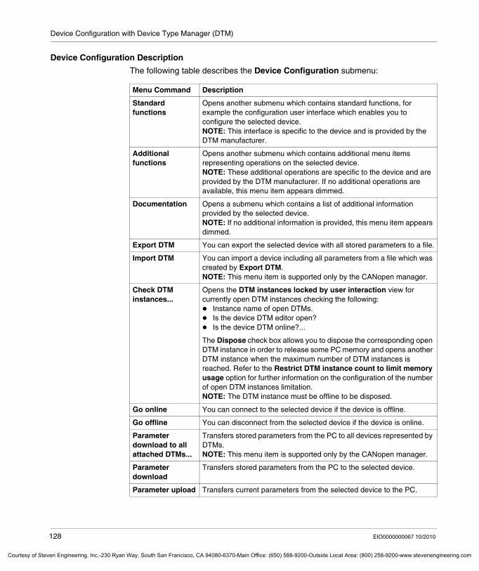
Device Configuration with Device Type Manager (DTM)
Courtesy of St
Device Configuration Description
The following table describes the Device Configuration submenu:
Menu Command Description
Standard functions
Opens another submenu which contains standard functions, for example the configuration user interface which enables you to configure the selected device. NOTE: This interface is specific to the device and is provided by the DTM manufacturer.
Additional functions
Opens another submenu which contains additional menu items representing operations on the selected device. NOTE: These additional operations are specific to the device and are provided by the DTM manufacturer. If no additional operations are available, this menu item appears dimmed.
Documentation Opens a submenu which contains a list of additional information provided by the selected device.NOTE: If no additional information is provided, this menu item appears dimmed.
Export DTM You can export the selected device with all stored parameters to a file.
Import DTM You can import a device including all parameters from a file which was created by Export DTM.NOTE: This menu item is supported only by the CANopen manager.
Check DTM instances...
Opens the DTM instances locked by user interaction view for currently open DTM instances checking the following:
Instance name of open DTMs.Is the device DTM editor open?Is the device DTM online?...
The Dispose check box allows you to dispose the corresponding open DTM instance in order to release some PC memory and opens another DTM instance when the maximum number of DTM instances is reached. Refer to the Restrict DTM instance count to limit memory usage option for further information on the configuration of the number of open DTM instances limitation.NOTE: The DTM instance must be offline to be disposed.
Go online You can connect to the selected device if the device is offline.
Go offline You can disconnect from the selected device if the device is online.
Parameter download to all attached DTMs...
Transfers stored parameters from the PC to all devices represented by DTMs.NOTE: This menu item is supported only by the CANopen manager.
Parameter download
Transfers stored parameters from the PC to the selected device.
Parameter upload Transfers current parameters from the selected device to the PC.
128 EIO0000000067 10/2010
even Engineering, Inc.-230 Ryan Way, South San Francisco, CA 94080-6370-Main Office: (650) 588-9200-Outside Local Area: (800) 258-9200-www.stevenengineering.com
EIO0000000067 10/2010
Courtesy of Steven Engineering, Inc.-230 Ryan Way, South San Francisco, CA 94080-6370-Main Office: (650) 588-9200-Outside Local Ar
7
Program
EIO0000000067 10/2010
Program
What's in this Chapter?
This chapter contains the following sections:
Section Topic Page
7.1 General Information 130
7.2 Managing the Application Objects 133
7.3 Adding Devices 147
7.4 Managing the Libraries 158
7.5 Managing the Communication Ports 176
7.6 SoMachine Commands 195
7.7 SoMachine Controller-HMI Data Exchange 202
7.8 SoMachine Templates 212
7.9 Managing Device Templates 224
7.10 Managing Function Templates 234
7.11 Transferring and Running Applications 243
129
ea: (800) 258-9200-www.stevenengineering.com
Program
Courtesy of St
7.1 General Information
General Description of the Program Tab
Overview
The Program tab is only displayed after you have opened a SoMachine project.
It provides access to the CoDeSys programming environment. Any configuration settings that were already performed in the Configuration tab are displayed in the Devices view and can be modified, deleted and / or added here. Any changes performed in this view will also be available in the Configuration tab.
130 EIO0000000067 10/2010
even Engineering, Inc.-230 Ryan Way, South San Francisco, CA 94080-6370-Main Office: (650) 588-9200-Outside Local Area: (800) 258-9200-www.stevenengineering.com
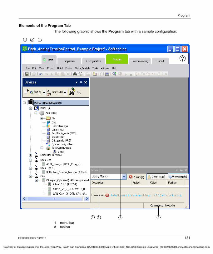
Program
Courtesy o
Elements of the Program Tab
The following graphic shows the Program tab with a sample configuration:
1 menu bar2 toolbar
EIO0000000067 10/2010 131
f Steven Engineering, Inc.-230 Ryan Way, South San Francisco, CA 94080-6370-Main Office: (650) 588-9200-Outside Local Area: (800) 258-9200-www.stevenengineering.com
Program
Courtesy of St
3 editor multi-tabbed view4 Messages pane5 information and status line6 status bar7 Devices pane
This user interface provides several dockable panes you can open via the View menu. You can arrange the different panes within the SoMachine window according to your individual preferences.
132 EIO0000000067 10/2010
even Engineering, Inc.-230 Ryan Way, South San Francisco, CA 94080-6370-Main Office: (650) 588-9200-Outside Local Area: (800) 258-9200-www.stevenengineering.com
Program
Courtesy o
7.2 Managing the Application Objects
What's in this Section?
This section contains the following topics:
Topic Page
Adding Tasks 134
Adding and Declaring POUs 135
Adding Libraries 137
Adding and Declaring Remanent Variables 140
Adding a Symbol Configuration 143
Adding Other Objects 144
Introduction to Data Logging 145
EIO0000000067 10/2010 133
f Steven Engineering, Inc.-230 Ryan Way, South San Francisco, CA 94080-6370-Main Office: (650) 588-9200-Outside Local Area: (800) 258-9200-www.stevenengineering.com
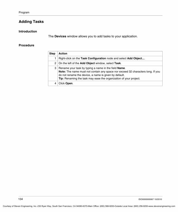
Program
Courtesy of St
Adding Tasks
Introduction
The Devices window allows you to add tasks to your application.
Procedure
Step Action
1 Right-click on the Task Configuration node and select Add Object....
2 On the left of the Add Object window, select Task.
3 Rename your task by typing a name in the field Name.Note: The name must not contain any space nor exceed 32 characters long. If you do not rename the device, a name is given by default.Tip: Renaming the task may ease the organization of your project.
4 Click Open.
134 EIO0000000067 10/2010
even Engineering, Inc.-230 Ryan Way, South San Francisco, CA 94080-6370-Main Office: (650) 588-9200-Outside Local Area: (800) 258-9200-www.stevenengineering.com
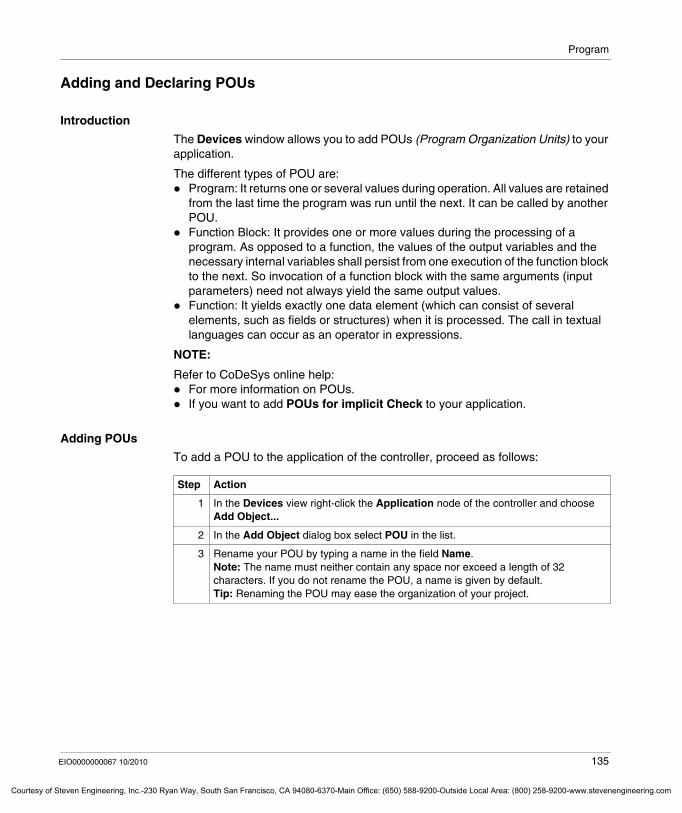
Program
Courtesy o
Adding and Declaring POUs
Introduction
The Devices window allows you to add POUs (Program Organization Units) to your application.
The different types of POU are:Program: It returns one or several values during operation. All values are retained from the last time the program was run until the next. It can be called by another POU.Function Block: It provides one or more values during the processing of a program. As opposed to a function, the values of the output variables and the necessary internal variables shall persist from one execution of the function block to the next. So invocation of a function block with the same arguments (input parameters) need not always yield the same output values.Function: It yields exactly one data element (which can consist of several elements, such as fields or structures) when it is processed. The call in textual languages can occur as an operator in expressions.
NOTE:
Refer to CoDeSys online help:For more information on POUs.If you want to add POUs for implicit Check to your application.
Adding POUs
To add a POU to the application of the controller, proceed as follows:
Step Action
1 In the Devices view right-click the Application node of the controller and choose Add Object...
2 In the Add Object dialog box select POU in the list.
3 Rename your POU by typing a name in the field Name.Note: The name must neither contain any space nor exceed a length of 32 characters. If you do not rename the POU, a name is given by default.Tip: Renaming the POU may ease the organization of your project.
EIO0000000067 10/2010 135
f Steven Engineering, Inc.-230 Ryan Way, South San Francisco, CA 94080-6370-Main Office: (650) 588-9200-Outside Local Area: (800) 258-9200-www.stevenengineering.com
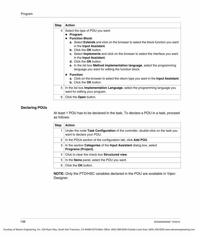
Program
Courtesy of St
Declaring POUs
At least 1 POU has to be declared in the task. To declare a POU in a task, proceed as follows:
NOTE: Only the PTO/HSC variables declared in the POU are available in Vijeo-Designer.
4 Select the type of POU you want:ProgramFunction Block:a. Select Extends and click on the browser to select the block function you want
in the Input Assistant.b. Click the OK button.c. Select Implements and click on the browser to select the interface you want
in the Input Assistant.d. Click the OK button.e. In the list box Method implementation language, select the programming
language you want for editing the function block.
Function:a. Click on the browser to select the return type you want in the Input Assistant.b. Click the OK button.
5 In the list box Implementation Language, select the programming language you want for editing your program.
6 Click the Open button.
Step Action
Step Action
1 Under the node Task Configuration of the controller, double-click on the task you want to declare your POU.
2 In the POUs section of the configuration tab, click Add POU.
3 In the section Categories of the Input Assistant dialog box, select Programs (Project).
4 Click to clear the check box Structured view.
5 In the Items panel, select the POU you want.
6 Click the OK button.
136 EIO0000000067 10/2010
even Engineering, Inc.-230 Ryan Way, South San Francisco, CA 94080-6370-Main Office: (650) 588-9200-Outside Local Area: (800) 258-9200-www.stevenengineering.com
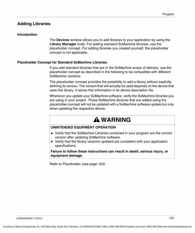
Program
Courtesy o
Adding Libraries
Introduction
The Devices window allows you to add libraries to your application by using the Library Manager node. For adding standard SoMachine libraries, use the placeholder concept. For adding libraries you created yourself, the placeholder concept is not applicable.
Placeholder Concept for Standard SoMachine Libraries
If you add standard libraries that are in the SoMachine scope of delivery, use the placeholder concept as described in the following to be compatible with different SoMachine versions.
The placeholder concept provides the possibility to add a library without explicitly defining its version. The version that will actually be used depends on the device that uses this library. It stores this information in its device description file.
Whenever you update your SoMachine software, verify the SoMachine libraries you are using in your project. Those SoMachine libraries that are added using the placeholder concept will not be updated with a SoMachine software update but only when updating the respective device.
Refer to Placeholder (see page 163).
WARNINGUNINTENDED EQUIPMENT OPERATION
Verify that the SoMachine Libraries contained in your program are the correct version after updating SoMachine software.Verify that the library versions updated are consistent with your application specifications.
Failure to follow these instructions can result in death, serious injury, or equipment damage.
EIO0000000067 10/2010 137
f Steven Engineering, Inc.-230 Ryan Way, South San Francisco, CA 94080-6370-Main Office: (650) 588-9200-Outside Local Area: (800) 258-9200-www.stevenengineering.com
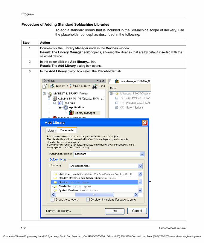
Program
Courtesy of St
Procedure of Adding Standard SoMachine Libraries
To add a standard library that is included in the SoMachine scope of delivery, use the placeholder concept as described in the following:
Step Action
1 Double-click the Library Manager node in the Devices window.Result: The Library Manager editor opens, showing the libraries that are by default inserted with the selected device.
2 In the editor click the Add library... link.Result: The Add Library dialog box opens.
3 In the Add Library dialog box select the Placeholder tab.
138 EIO0000000067 10/2010
even Engineering, Inc.-230 Ryan Way, South San Francisco, CA 94080-6370-Main Office: (650) 588-9200-Outside Local Area: (800) 258-9200-www.stevenengineering.com
Program
Courtesy o
NOTE: Please note that only those libraries defined in the Devices window require the placeholder concept. The placeholder concept is not applicable for libraries you define in the POU window.
4 In the Placeholder tab configure the following:Select the Placeholder name from the list. The placeholder names are identical to the library names, except of Schneider Electric libraries that are extended by the prefix SE_).Define the Default library by selecting the suitable library from the list. This setting only defines the library type that will be inserted. The library version that will actually be used is defined by the device.
5 Click OK.Result: The library will be added to the Library Manager, like for example SE_Standard = Standard, 33.3.1.10 (System).
Step Action
EIO0000000067 10/2010 139
f Steven Engineering, Inc.-230 Ryan Way, South San Francisco, CA 94080-6370-Main Office: (650) 588-9200-Outside Local Area: (800) 258-9200-www.stevenengineering.com
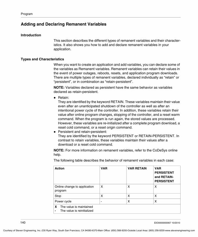
Program
Courtesy of St
Adding and Declaring Remanent Variables
Introduction
This section describes the different types of remanent variables and their character-istics. It also shows you how to add and declare remanent variables in your application.
Types and Characteristics
When you want to create an application and add variables, you can declare some of the variables as Remanent variables. Remanent variables can retain their values in the event of power outages, reboots, resets, and application program downloads. There are multiple types of remanent variables, declared individually as “retain” or “persistent”, or in combination as “retain-persistent”.
NOTE: Variables declared as persistent have the same behavior as variables declared as retain-persistent.
Retain:They are identified by the keyword RETAIN. These variables maintain their value even after an unanticipated shutdown of the controller as well as after an intentional power cycle of the controller. In addition, these variables retain their value after online program changes, stopping of the controller, and a reset warm command. When the program is run again, the stored values are processed. However, these variables are re-initialized after a complete program download, a reset cold command, or a reset origin command.Persistent and retain-persistent: They are identified by the keyword PERSISTENT or RETAIN-PERSISTENT. In contrast to retain variables, these variables maintain their values after a download or a reset cold command.
NOTE: For more information on remanent variables, refer to the CoDeSys online help.
The following table describes the behavior of remanent variables in each case:
Action VAR VAR RETAIN VAR PERSISTENT and RETAIN-PERSISTENT
Online change to application program
X X X
Stop X X X
Power cycle - X X
X The value is maintained- The value is reinitialized
140 EIO0000000067 10/2010
even Engineering, Inc.-230 Ryan Way, South San Francisco, CA 94080-6370-Main Office: (650) 588-9200-Outside Local Area: (800) 258-9200-www.stevenengineering.com
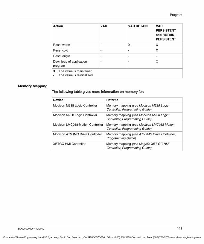
Program
Courtesy o
Memory Mapping
The following table gives more information on memory for:
Reset warm - X X
Reset cold - - X
Reset origin - - -
Download of application program
- - X
Action VAR VAR RETAIN VAR PERSISTENT and RETAIN-PERSISTENT
X The value is maintained- The value is reinitialized
Device Refer to
Modicon M238 Logic Controller Memory mapping (see Modicon M238 Logic Controller, Programming Guide)
Modicon M258 Logic Controller Memory mapping (see Modicon M258 Logic Controller, Programming Guide)
Modicon LMC058 Motion Controller Memory mapping (see Modicon LMC058 Motion Controller, Programming Guide)
Modicon ATV IMC Drive Controller Memory mapping (see ATV IMC Drive Controller, Programming Guide)
XBTGC HMI Controller Memory mapping (see Magelis XBT GC HMI Controller, Programming Guide)
EIO0000000067 10/2010 141
f Steven Engineering, Inc.-230 Ryan Way, South San Francisco, CA 94080-6370-Main Office: (650) 588-9200-Outside Local Area: (800) 258-9200-www.stevenengineering.com
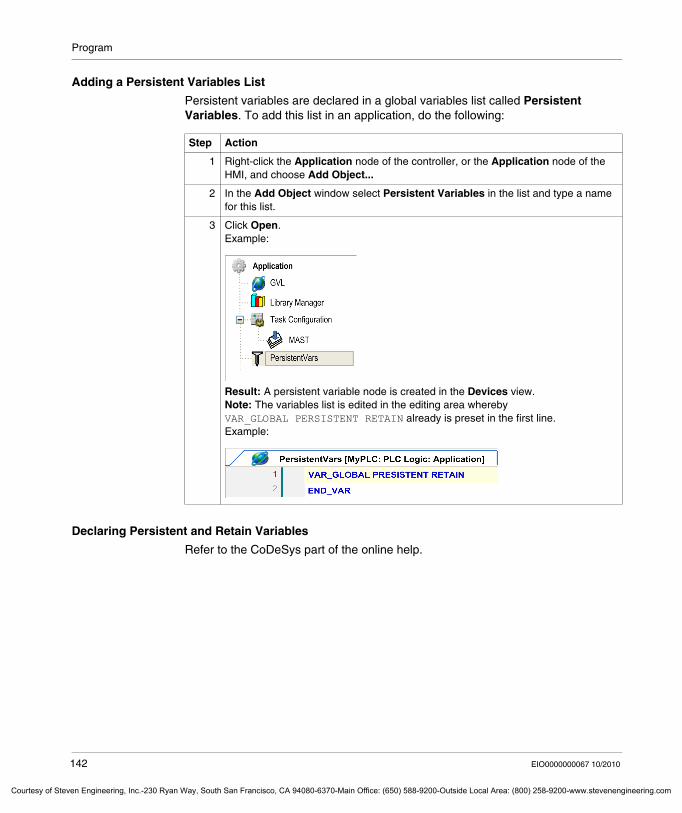
Program
Courtesy of St
Adding a Persistent Variables List
Persistent variables are declared in a global variables list called Persistent Variables. To add this list in an application, do the following:
Declaring Persistent and Retain Variables
Refer to the CoDeSys part of the online help.
Step Action
1 Right-click the Application node of the controller, or the Application node of the HMI, and choose Add Object...
2 In the Add Object window select Persistent Variables in the list and type a name for this list.
3 Click Open.Example:
Result: A persistent variable node is created in the Devices view.Note: The variables list is edited in the editing area whereby VAR_GLOBAL PERSISTENT RETAIN already is preset in the first line.Example:
142 EIO0000000067 10/2010
even Engineering, Inc.-230 Ryan Way, South San Francisco, CA 94080-6370-Main Office: (650) 588-9200-Outside Local Area: (800) 258-9200-www.stevenengineering.com
Program
Courtesy o
Adding a Symbol Configuration
Prerequisites
Variables that will be exchanged between the controller and (multiple) HMI devices using the transparent SoMachine protocol (see SoMachine, Introduction) must be published in the controller by means of the Symbol configuration. They will then be available as SoMachine variables in Vijeo-Designer.
Opening the Symbol Configuration
To open the Symbol configuration proceed as follows:
NOTE: Only 1 symbol configuration node can be created per device.
For details on the variables interchange between the controller and HMI part refer to the chapter SoMachine Controller-HMI Data Exchange (see page 202).
Step Action
1 Right-click the Application node of the controller and select the Add Object... command.Result: The Add Object dialog box will be displayed.
2 In the Add Object dialog box select the entry Symbol Configuration from the list on the left-hand side.
3 Click Open.Result: A Symbol configuration item is created under the Application node in the Devices window. The Symbol configuration editor will be displayed on the right-hand side.
EIO0000000067 10/2010 143
f Steven Engineering, Inc.-230 Ryan Way, South San Francisco, CA 94080-6370-Main Office: (650) 588-9200-Outside Local Area: (800) 258-9200-www.stevenengineering.com
Program
Courtesy of St
Adding Other Objects
Available Objects
The devices view also allows you to add the following objects to your application:CAM table is only available for SoftMotion devices for motion control in tabular or textual form.Data Server establishes a point-to-point connection between the local application and a remote data source (i.e. an OPC server).DataLogManager is used to create customer-specific log files on process or machine status information.DUT is used to create your own data type.Global Variable List is used to declare global variables which will be available in the whole application.Image Pool is the images repository for the project.Interface is used to organize methods which are used by function blocks. An interface is a POU describing a collection of method-prototypes. POUs for implicit checks provide check functionality for array and range boundaries, divisions by zero and pointers during runtimeRelocation Table is an editor that allows you to work with the relocation table of the system variables.Text List is used for multi-language support or dynamic text.Trace is used to configure and to display a sampling of the values of variables, i.e. the online progression of the values read from the controller over a certain time.Visualization allows you to create graphical representation of your system for monitoring.Visualization Manager is used to handle some common settings for all visualizations assigned to the current applicationVisualizationinstance allows you to create visualization instances.
For more information concerning these objects, refer to the CoDeSys part of the online help.
Adding Generic Objects
To add generic objects to the application of the controller, or to the application of the HMI, do the following.
Step Action
1 Click on the Application node of the controller, and choose Add Object...
2 In the Add Object window, select the object you want to add.
3 Click Open.
144 EIO0000000067 10/2010
even Engineering, Inc.-230 Ryan Way, South San Francisco, CA 94080-6370-Main Office: (650) 588-9200-Outside Local Area: (800) 258-9200-www.stevenengineering.com
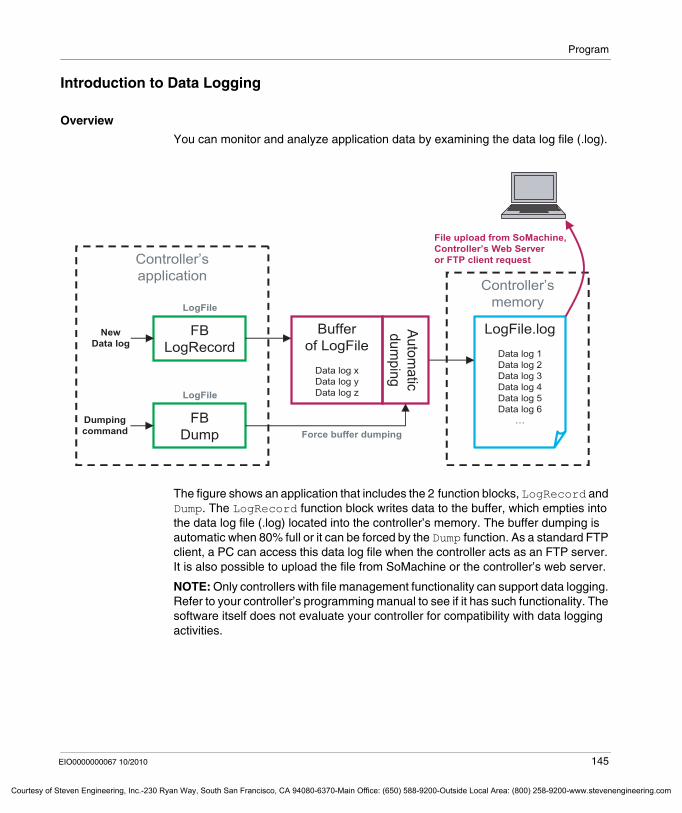
Program
Courtesy o
Introduction to Data Logging
Overview
You can monitor and analyze application data by examining the data log file (.log).
The figure shows an application that includes the 2 function blocks, LogRecord and Dump. The LogRecord function block writes data to the buffer, which empties into the data log file (.log) located into the controller’s memory. The buffer dumping is automatic when 80% full or it can be forced by the Dump function. As a standard FTP client, a PC can access this data log file when the controller acts as an FTP server. It is also possible to upload the file from SoMachine or the controller’s web server.
NOTE: Only controllers with file management functionality can support data logging. Refer to your controller’s programming manual to see if it has such functionality. The software itself does not evaluate your controller for compatibility with data logging activities.
FBLogRecord
FBDump
Bufferof LogFile
Data log xData log yData log z
NewData log
LogFile.log
Data log 1Data log 2Data log 3Data log 4Data log 5Data log 6
…
Automatic
dumping
Force buffer dumping
Controller’sapplication
Controller’smemory
File upload from SoMachine,Controller’s Web Serveror FTP client request
LogFile
LogFile
Dumpingcommand
EIO0000000067 10/2010 145
f Steven Engineering, Inc.-230 Ryan Way, South San Francisco, CA 94080-6370-Main Office: (650) 588-9200-Outside Local Area: (800) 258-9200-www.stevenengineering.com
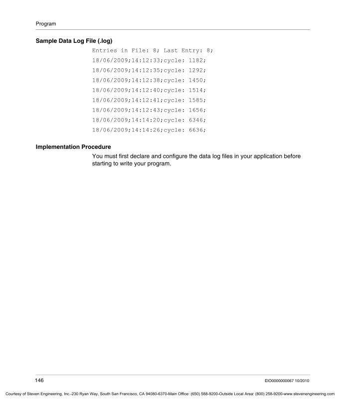
Program
Courtesy of St
Sample Data Log File (.log)
Entries in File: 8; Last Entry: 8;
18/06/2009;14:12:33;cycle: 1182;
18/06/2009;14:12:35;cycle: 1292;
18/06/2009;14:12:38;cycle: 1450;
18/06/2009;14:12:40;cycle: 1514;
18/06/2009;14:12:41;cycle: 1585;
18/06/2009;14:12:43;cycle: 1656;
18/06/2009;14:14:20;cycle: 6346;
18/06/2009;14:14:26;cycle: 6636;
Implementation Procedure
You must first declare and configure the data log files in your application before starting to write your program.
146 EIO0000000067 10/2010
even Engineering, Inc.-230 Ryan Way, South San Francisco, CA 94080-6370-Main Office: (650) 588-9200-Outside Local Area: (800) 258-9200-www.stevenengineering.com
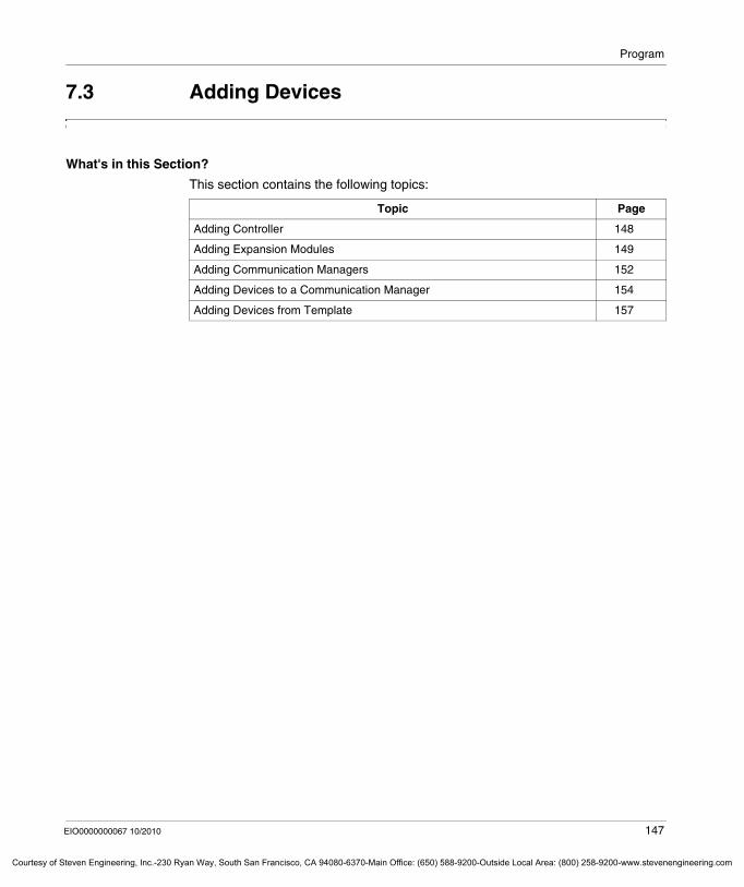
Program
Courtesy o
7.3 Adding Devices
What's in this Section?
This section contains the following topics:
Topic Page
Adding Controller 148
Adding Expansion Modules 149
Adding Communication Managers 152
Adding Devices to a Communication Manager 154
Adding Devices from Template 157
EIO0000000067 10/2010 147
f Steven Engineering, Inc.-230 Ryan Way, South San Francisco, CA 94080-6370-Main Office: (650) 588-9200-Outside Local Area: (800) 258-9200-www.stevenengineering.com
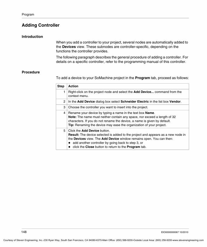
Program
Courtesy of St
Adding Controller
Introduction
When you add a controller to your project, several nodes are automatically added to the Devices view. These subnodes are controller-specific, depending on the functions the controller provides.
The following paragraph describes the general procedure of adding a controller. For details on a specific controller, refer to the programming manual of this controller.
Procedure
To add a device to your SoMachine project in the Program tab, proceed as follows:
Step Action
1 Right-click on the project node and select the Add Device... command from the context menu.
2 In the Add Device dialog box select Schneider Electric in the list box Vendor.
3 Choose the controller you want to insert into the project.
4 Rename your device by typing a name in the text box Name.Note: The name must neither contain any space, nor exceed a length of 32 characters. If you do not rename the device, a name is given by default.Tip: Renaming the device may ease the organization of your project.
5 Click the Add Device button.Result: The device selected is added to the project and appears as a new node in the Devices view. The Add Device window remains open. You can then:
add another controller by going back to step 3, orclick the Close button to return to the Program tab.
148 EIO0000000067 10/2010
even Engineering, Inc.-230 Ryan Way, South San Francisco, CA 94080-6370-Main Office: (650) 588-9200-Outside Local Area: (800) 258-9200-www.stevenengineering.com
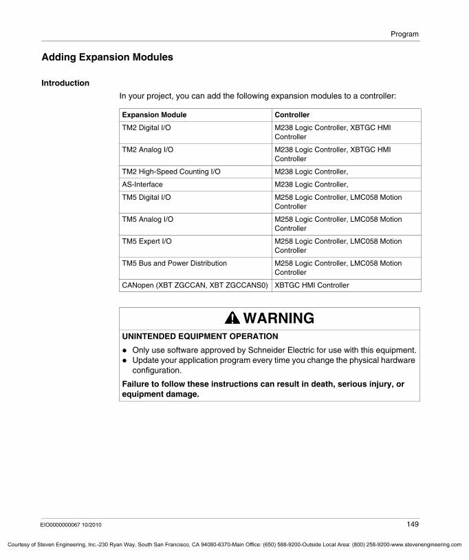
Program
Courtesy o
Adding Expansion Modules
Introduction
In your project, you can add the following expansion modules to a controller:
Expansion Module Controller
TM2 Digital I/O M238 Logic Controller, XBTGC HMI Controller
TM2 Analog I/O M238 Logic Controller, XBTGC HMI Controller
TM2 High-Speed Counting I/O M238 Logic Controller,
AS-Interface M238 Logic Controller,
TM5 Digital I/O M258 Logic Controller, LMC058 Motion Controller
TM5 Analog I/O M258 Logic Controller, LMC058 Motion Controller
TM5 Expert I/O M258 Logic Controller, LMC058 Motion Controller
TM5 Bus and Power Distribution M258 Logic Controller, LMC058 Motion Controller
CANopen (XBT ZGCCAN, XBT ZGCCANS0) XBTGC HMI Controller
WARNINGUNINTENDED EQUIPMENT OPERATION
Only use software approved by Schneider Electric for use with this equipment.Update your application program every time you change the physical hardware configuration.
Failure to follow these instructions can result in death, serious injury, or equipment damage.
EIO0000000067 10/2010 149
f Steven Engineering, Inc.-230 Ryan Way, South San Francisco, CA 94080-6370-Main Office: (650) 588-9200-Outside Local Area: (800) 258-9200-www.stevenengineering.com
Program
Courtesy of St
Procedure of Adding Expansion Modules
To add expansion modules to your device, proceed as follows:
Step Action
1 Click in the graphical configuration editor on the area Add Expa... of the device.
Result: The Add object dialog box opens, displaying only those expansion modules that can be connected to the selected device like in the graphic below for an M238 logic controller.
150 EIO0000000067 10/2010
even Engineering, Inc.-230 Ryan Way, South San Francisco, CA 94080-6370-Main Office: (650) 588-9200-Outside Local Area: (800) 258-9200-www.stevenengineering.com
Program
Courtesy o
The expansion modules added to a device are displayed on the right side of the device icon. You can hide or display them by clicking the small arrow above the Add Expa... button. To configure them, double-click their icons.
NOTE: When you add a TWDNOI10M3 object, that is an AS-Interface Master Module, the corresponding Virtual AS interface bus fieldbus manager will automatically be inserted. To add AS-Interface slave modules, proceed as described in the Adding Slave Devices to a Fieldbus Manager (see page 76) paragraph above.
For more information about adding expansion modules refer to the following Programming Guides of the controllers:
XBTGC HMI Controller - Programming GuideM238 Logic Controller - Programming GuideM258 Logic Controller - Programming Guide for TM5 and PCI Expansion ModulesLMC058 Logic Controller - Programming Guide for TM5 and PCI Expansion Modules
Expansion Module Configuration
For more information about modules configuration refer to the following Programming Guides of the expansion modules:
TM2 Expansion Modules Configuration - Programming GuideTM5 Expansion Modules Configuration - Programming GuideTM5 PCI Modules Configuration - Programming Guide
Monitoring the Expansion Bus Status
Use the following function regularly to monitor the expansion bus status:
2 Select the expansion module you want to add to the device from the list on the left-hand side and click the Add and close button.Result: The expansion module will be displayed in the graphical configuration editor on the right-hand side of the device.
Step Action
Type of Expansion Modules Function
TM5 GVL TM5_Module_R
EIO0000000067 10/2010 151
f Steven Engineering, Inc.-230 Ryan Way, South San Francisco, CA 94080-6370-Main Office: (650) 588-9200-Outside Local Area: (800) 258-9200-www.stevenengineering.com
Program
Courtesy of St
Adding Communication Managers
Overview
Communication managers are mandatory to activate and configure the controller’s hardware bus interface, for example CANbus or Serial line.
2 types of communication managers exist:Fieldbus Managers which allow to configure fieldbus devices (for example CANopen slaves or Modbus slaves)general communication managers
Communication managers available in SoMachine are listed below:
Interface Type
Name Description
Serial line ASCII Manager Used to transmit and / or receive data with a simple device.
Serial line SoMachine-Network Manager Must be used if you want to connect an XBTGT, XBTGK or XBTGH HMI through SoMachine protocol offering transparent exchange of data and multiple download capability (download of controller and HMI applications through 1 unique connection PC-controller or PC-HMI).
Serial line Modbus IOScanner Modbus RTU or ASCII protocol manager used to define implicit exchanges (I/O scanning) with Modbus slave devices.
Serial line Modbus Manager Used for Modbus RTU or ASCII protocol in master or slave mode.
CANbus CANopen Optimized CANopen manager for optimized controllers (M238, XBTGC, XBTGT, XBTGK, ATV IMC)
CANbus CANopen Performance CANopen manager for performance controllers (M258 and LMC058)
CANbus CANmotion CANmotion manager for LMC058 Motion Controller CAN1 port only.
Ethernet Modbus TCP Slave Device Modbus TCP manager for controllers with Ethernet port.
Ethernet EtherNet/IP EtherNet/IP manager for controllers with Ethernet port.
152 EIO0000000067 10/2010
even Engineering, Inc.-230 Ryan Way, South San Francisco, CA 94080-6370-Main Office: (650) 588-9200-Outside Local Area: (800) 258-9200-www.stevenengineering.com
Program
Courtesy o
Adding the Communication Manager
Proceed as follows to configure the communication manager:
NOTE: You can only add 1 manager per interface (Serial line or CANbus).
Step Action
1 In the Devices window right-click the bus interface (Serial Line or CANbus) and select Add Device... from the context menu.Result: The Add Device dialog box will be displayed.
2 In the Add Device dialog box select <All vendors> from the list box Vendor.Note: You can sort the devices by brand by clicking on the list box Vendor.
3 Select the Communication manager from the list below.
4 Rename your device by typing a name in the Name textbox.Note: The name must not contain any space. If you do not rename the device, a name is given by default.
5 Click the Add Device button.
6 Configure the Communication manager.
EIO0000000067 10/2010 153
f Steven Engineering, Inc.-230 Ryan Way, South San Francisco, CA 94080-6370-Main Office: (650) 588-9200-Outside Local Area: (800) 258-9200-www.stevenengineering.com
Program
Courtesy of St
Adding Devices to a Communication Manager
Overview
You can add Modbus and CANopen field devices to the communication manager by executing the Add Device command.
As a prerequisite the device must be available in the Device Repository (see the CoDeSys part of the online help for details on how to import device descriptions, for example importing CANopen EDS files into SoMachine).
Adding Devices
Access to Diagnostic Information
To get diagnostic information of devices on CANopen use the CiA 405 library (see SoMachine, CANopen Management Functions, CAA CiA 405 Library Guide).
Access to Configuration Diagnostic
To optimize the CAN master performance, CAN diagnostics are external from the CAN master in the controller. The CAN diagnostic structure is defined in the CanConfig Extern (version 3.3.1.40) library available in the Library Manager.
The structure g_aNetDiagnosis contains the most recent diagnostic information from the slaves. The structure is updated every time a slave is configured, for whatever reasons.
Step Action
1 Right-click the field device manager item (CANopen or Modbus manager) in the Devices window and select Add Device... from the context menu.Result: The Add Device dialog box will be displayed.
2 In the Add Device dialog box select <All vendors> from the list box Vendor.Note: You can sort the devices by brand by clicking on the list box Vendor.
3 Select the device of your choice from the list below.
4 Rename your device by typing a name in the Name textbox.Note: The name must not contain any space. If you do not rename the device, a name is given by default.Tip: Renaming the device may ease the organization of your project.
5 Click the Add Device button.Result: The field device is added to the field device manager.NOTE: The Add Device dialog box remains open.
You can now:add another device by going back to step 2click the Close button
154 EIO0000000067 10/2010
even Engineering, Inc.-230 Ryan Way, South San Francisco, CA 94080-6370-Main Office: (650) 588-9200-Outside Local Area: (800) 258-9200-www.stevenengineering.com
Program
Courtesy o
This structure can be used within the program to do the following:Monitoring the response of the slave(s) configured via SDO messages.Monitoring the master for any abort messages from the slaves before allowing a machine / application start-up.
This structure must be in place and active within the user application during testing, debugging and commissioning of the application. When the machine and its controlling application has been commissioned and is stable, then it would be possible to disable this code from execution.
However, if during the lifecycle of an application and the machine or process that controls, slaves are added or replaced in the operational system, then the diagnostic structure should continue to remain active in the application.
After adding the CanConfig Extern library to your application, use the Net Diagnostic definition within your application to test for SDO abort messages from the CAN slaves.
To help you better understand the use of the CAN diagnostic data structure, the following code example is provided:
IF g_aNetDiagnosis[CAN_Net_Number].ctSDOErrorCounter = 0 THEN (* No error is detected in the configuration*)
ELSE(* An error has been detected during configuration. Get
the latest error information.*)// node ID of the slave which sent the abort codeReadLastErrorNodeID :=
g_aNetDiagnosis[CAN_Net_Number].usiNodeID;// index used in the aborted SDOReadLastErrorIndex :=
g_aNetDiagnosis[CAN_Net_Number].wIndex;
WARNINGUNINTENDED EQUIPMENT OPERATION
Use the g_aNetDiagnosis data structure within the application to monitor CAN slave responses to configuration commands.Verify that the application does not start-up or put the machine or process in an operational state, in the event of receiving SDO abort message(s) from any of the CAN slaves.
Failure to follow these instructions can result in death, serious injury, or equipment damage.
EIO0000000067 10/2010 155
f Steven Engineering, Inc.-230 Ryan Way, South San Francisco, CA 94080-6370-Main Office: (650) 588-9200-Outside Local Area: (800) 258-9200-www.stevenengineering.com
Program
Courtesy of St
// subIndex used in the aborted SDOReadLastErrorSubIndex :=
g_aNetDiagnosis[CAN_Net_Number].bySubIndex;//SDO abort codeReadLastErrorSdoAbortCode := g_aNetDiagnosis
[CAN_Net_Number].udiAbortCode;(* Do not allow the start-up or other operation of the
machine or process *)END_IF
NOTE: In this example, the CAN_Net_Number would be 0 for the CAN0 port, and if the controller is so equipped, 1 for the CAN1port.
156 EIO0000000067 10/2010
even Engineering, Inc.-230 Ryan Way, South San Francisco, CA 94080-6370-Main Office: (650) 588-9200-Outside Local Area: (800) 258-9200-www.stevenengineering.com

Program
Courtesy o
Adding Devices from Template
Overview
It is also possible to add a new device using a device template. For a description of this procedure refer to the Managing Device Templates section (see page 226).
EIO0000000067 10/2010 157
f Steven Engineering, Inc.-230 Ryan Way, South San Francisco, CA 94080-6370-Main Office: (650) 588-9200-Outside Local Area: (800) 258-9200-www.stevenengineering.com
Program
Courtesy of St
7.4 Managing the Libraries
What's in this Section?
This section contains the following topics:
Topic Page
Generalities About Libraries 159
Library Management in SoMachine 162
Schneider Electric Libraries 165
Other Libraries Used in SoMachine 172
Creating Your Own Libraries 175
158 EIO0000000067 10/2010
even Engineering, Inc.-230 Ryan Way, South San Francisco, CA 94080-6370-Main Office: (650) 588-9200-Outside Local Area: (800) 258-9200-www.stevenengineering.com
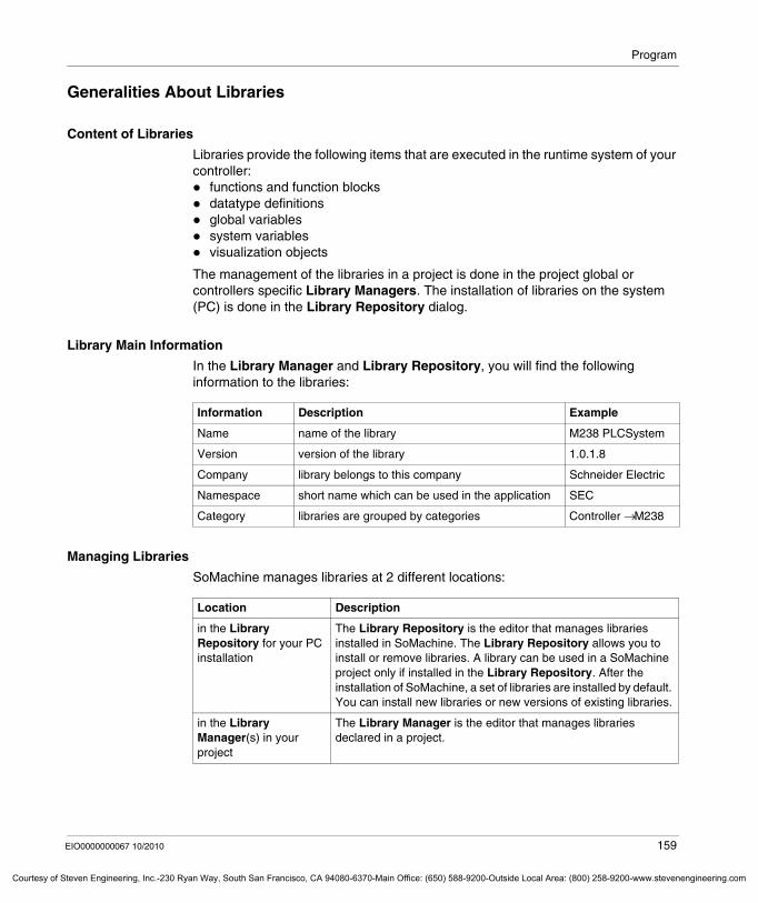
Program
Courtesy o
Generalities About Libraries
Content of Libraries
Libraries provide the following items that are executed in the runtime system of your controller:
functions and function blocksdatatype definitionsglobal variablessystem variablesvisualization objects
The management of the libraries in a project is done in the project global or controllers specific Library Managers. The installation of libraries on the system (PC) is done in the Library Repository dialog.
Library Main Information
In the Library Manager and Library Repository, you will find the following information to the libraries:
Managing Libraries
SoMachine manages libraries at 2 different locations:
Information Description Example
Name name of the library M238 PLCSystem
Version version of the library 1.0.1.8
Company library belongs to this company Schneider Electric
Namespace short name which can be used in the application SEC
Category libraries are grouped by categories Controller → M238
Location Description
in the Library Repository for your PC installation
The Library Repository is the editor that manages libraries installed in SoMachine. The Library Repository allows you to install or remove libraries. A library can be used in a SoMachine project only if installed in the Library Repository. After the installation of SoMachine, a set of libraries are installed by default. You can install new libraries or new versions of existing libraries.
in the Library Manager(s) in your project
The Library Manager is the editor that manages libraries declared in a project.
EIO0000000067 10/2010 159
f Steven Engineering, Inc.-230 Ryan Way, South San Francisco, CA 94080-6370-Main Office: (650) 588-9200-Outside Local Area: (800) 258-9200-www.stevenengineering.com
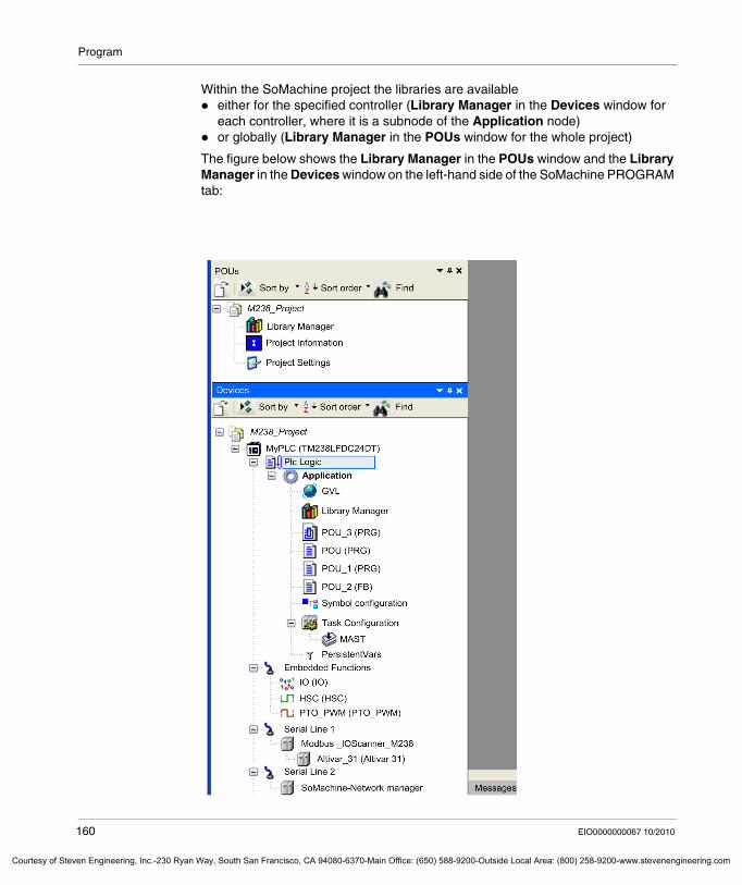
Program
Courtesy of St
Within the SoMachine project the libraries are available either for the specified controller (Library Manager in the Devices window for each controller, where it is a subnode of the Application node)or globally (Library Manager in the POUs window for the whole project)
The figure below shows the Library Manager in the POUs window and the Library Manager in the Devices window on the left-hand side of the SoMachine PROGRAM tab:
160 EIO0000000067 10/2010
even Engineering, Inc.-230 Ryan Way, South San Francisco, CA 94080-6370-Main Office: (650) 588-9200-Outside Local Area: (800) 258-9200-www.stevenengineering.com

Program
Courtesy o
For more information about library management, refer to CoDeSys online help: Basic Concepts of CoDeSys / Library Management.
For more information about Library Repository, refer to CoDeSys online help: Menu Commands / Installation / Library Repository.
For more information about Library Manager, refer to CoDeSys online help: Editors / Library Manager Editor.
In SoMachine, features embedded in libraries might be used for the automation as well as for the system (internal). In both cases, libraries are managed with the Library Manager of SoMachine.
EIO0000000067 10/2010 161
f Steven Engineering, Inc.-230 Ryan Way, South San Francisco, CA 94080-6370-Main Office: (650) 588-9200-Outside Local Area: (800) 258-9200-www.stevenengineering.com
Program
Courtesy of St
Library Management in SoMachine
Organization of the Libraries in the Repository
2 types of libraries exist:Automation libraries: their functions can be used by users in the automation
applications (program)System libraries: SoMachine internal libraries, not related to the automation
applications (program)
SoMachine default Company names:3S - Smart Software Solution GmbHCAA Technical WorkgroupSchneider ElectricSystem
The libraries are grouped in the following categories to provide a better overview:Application: libraries used in the automation applicationsCommunication: libraries used for specific communication featuresController: libraries dedicated to SoMachine controllersDevices: libraries dedicated to distributed devices management (TeSys, Altivar, Lexium)Intern: system libraries for SoMachine internal usage and controllers runtimesMiscellaneous: libraries not categorizedSolution: libraries dedicated to applications solutions (Packaging, Hoisting, Conveying)System: system libraries for SoMachine internal usage and controllers runtimesTarget: platform-specific librariesUtil: libraries providing additional utility functions
162 EIO0000000067 10/2010
even Engineering, Inc.-230 Ryan Way, South San Francisco, CA 94080-6370-Main Office: (650) 588-9200-Outside Local Area: (800) 258-9200-www.stevenengineering.com
Program
Courtesy o
Namespace
A library namespace is a symbol that allows the unique access to the attached library components (functions, function blocks, variables…). The use of namespaces is optional, but necessary if 2 components of 2 different libraries used in the same project have the same name. The full name <namespace>.<component> will then allow a unique access to the correct component.
A default namespace is defined for each library. Schneider Electric libraries default namespaces start with the prefix SE.
Default namespace of a library declared in a project can be customized in the library Properties editor called from the Library Manager (In the Library Manager of a project, right click on the library then select the Properties field).
Placeholder
Placeholder is a mechanism used to manage the compatibility between versions of devices and versions of libraries.
When SoMachine or existing devices are upgraded or when new devices are integrated, attached Device Description Files are installed. The Device Description File contains the placeholders that define versions of libraries compatible with the device version.
Case Description
1 There is a function block GEN in the library Util. The namespace of the library Util is Util. An instance of the function block GEN can be declared with or without the library namespace if the name GEN is unique within the project:MyGenerator: Util.GEN;or MyGenerator: GEN;
2 A function block GEN has been created within the project. The use of the library Util namespace will allow the system to access the function block GEN of the library Util. Without namespace, the project function block GEN will be accessed:MyGenerator_Util: Util.GEN;MyGenerator_Project: GEN;
3 Another library, also containing a function block called GEN, is declared in the project with namespace NewLib. The use of the namespace becomes mandatory to identify the correct function block GEN to be accessed:MyGenerator_Util: Util.GEN;MyGenerato_NewLib: NewLib.GEN;
EIO0000000067 10/2010 163
f Steven Engineering, Inc.-230 Ryan Way, South San Francisco, CA 94080-6370-Main Office: (650) 588-9200-Outside Local Area: (800) 258-9200-www.stevenengineering.com
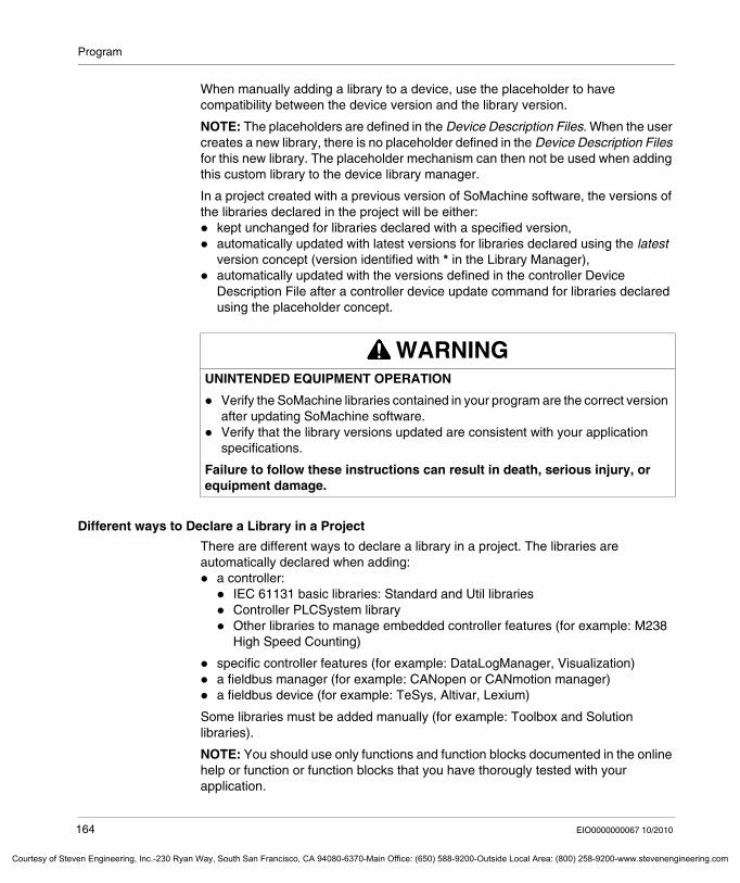
Program
Courtesy of St
When manually adding a library to a device, use the placeholder to have compatibility between the device version and the library version.
NOTE: The placeholders are defined in the Device Description Files. When the user creates a new library, there is no placeholder defined in the Device Description Files for this new library. The placeholder mechanism can then not be used when adding this custom library to the device library manager.
In a project created with a previous version of SoMachine software, the versions of the libraries declared in the project will be either:
kept unchanged for libraries declared with a specified version,automatically updated with latest versions for libraries declared using the latest version concept (version identified with * in the Library Manager),automatically updated with the versions defined in the controller Device Description File after a controller device update command for libraries declared using the placeholder concept.
Different ways to Declare a Library in a Project
There are different ways to declare a library in a project. The libraries are automatically declared when adding:
a controller:IEC 61131 basic libraries: Standard and Util librariesController PLCSystem libraryOther libraries to manage embedded controller features (for example: M238 High Speed Counting)
specific controller features (for example: DataLogManager, Visualization)a fieldbus manager (for example: CANopen or CANmotion manager)a fieldbus device (for example: TeSys, Altivar, Lexium)
Some libraries must be added manually (for example: Toolbox and Solution libraries).
NOTE: You should use only functions and function blocks documented in the online help or function or function blocks that you have thorougly tested with your application.
WARNINGUNINTENDED EQUIPMENT OPERATION
Verify the SoMachine libraries contained in your program are the correct version after updating SoMachine software.Verify that the library versions updated are consistent with your application specifications.
Failure to follow these instructions can result in death, serious injury, or equipment damage.
164 EIO0000000067 10/2010
even Engineering, Inc.-230 Ryan Way, South San Francisco, CA 94080-6370-Main Office: (650) 588-9200-Outside Local Area: (800) 258-9200-www.stevenengineering.com
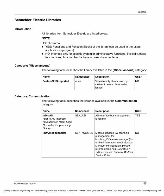
Program
Courtesy o
Schneider Electric Libraries
Introduction
All libraries from Schneider Electric are listed below.
NOTE:
USER column:YES: Functions and Function Blocks of the library can be used in the users applications (program).NO: Intended only for specific system or administrative functions. Typically, these functions and function blocks have no user documentation.
Category: (Miscellaneous)
The following table describes the library available in the (Miscellaneous) category:
Category: Communication
The following table describes the libraries available in the Communication category:
Name Namespace Description USER
FeatureNotSupported none Virtual empty library used by system to solve placeholder issues
NO
Name Namespace Description USER
IoDrvASIrefer to AS-Interface (see Modicon M238 Logic Controller, Programming Guide)
SEN_ASI AS-Interface bus management functions
YES
IoDrvModbusSerial SEN_MODBUS Modbus devices I/O scanning management for Modbus_IOScanner manager (for further information about Modbus Manager configuration, please refer to online help CoDeSys / Editors / Device Editors / Modbus Device Editor)
NO
EIO0000000067 10/2010 165
f Steven Engineering, Inc.-230 Ryan Way, South San Francisco, CA 94080-6370-Main Office: (650) 588-9200-Outside Local Area: (800) 258-9200-www.stevenengineering.com
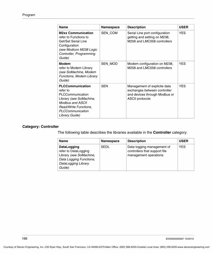
Program
Courtesy of St
Category: Controller
The following table describes the libraries available in the Controller category:
M2xx Communicationrefer to Functions to Get/Set Serial Line Configuration (see Modicon M238 Logic Controller, Programming Guide)
SEN_COM Serial Line port configuration getting and setting on M238, M258 and LMC058 controllers
YES
Modemrefer to Modem Library (see SoMachine, Modem Functions, Modem Library Guide)
SEN_MOD Modem configuration on M238, M258 and LMC058 controllers
YES
PLCCommunicationrefer to PLCCommunication Library (see SoMachine, Modbus and ASCII Read/Write Functions, PLCCommunication Library Guide)
SEN Management of explicite data exchanges between controller and devices through Modbus or ASCII protocols
YES
Name Namespace Description USER
Name Namespace Description USER
DataLoggingrefer to DataLogging Library (see SoMachine, Data Logging Functions, DataLogging Library Guide)
SEDL Data logging management of controllers that support file management operations
YES
166 EIO0000000067 10/2010
even Engineering, Inc.-230 Ryan Way, South San Francisco, CA 94080-6370-Main Office: (650) 588-9200-Outside Local Area: (800) 258-9200-www.stevenengineering.com
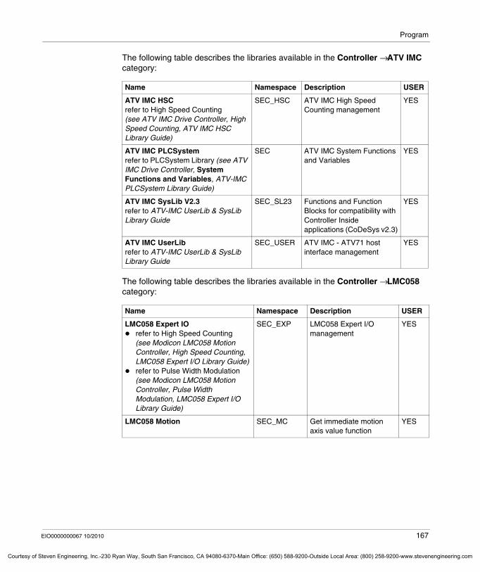
Program
Courtesy o
The following table describes the libraries available in the Controller → ATV IMC category:
The following table describes the libraries available in the Controller → LMC058 category:
Name Namespace Description USER
ATV IMC HSCrefer to High Speed Counting (see ATV IMC Drive Controller, High Speed Counting, ATV IMC HSC Library Guide)
SEC_HSC ATV IMC High Speed Counting management
YES
ATV IMC PLCSystemrefer to PLCSystem Library (see ATV IMC Drive Controller, System Functions and Variables, ATV-IMC PLCSystem Library Guide)
SEC ATV IMC System Functions and Variables
YES
ATV IMC SysLib V2.3refer to ATV-IMC UserLib & SysLib Library Guide
SEC_SL23 Functions and Function Blocks for compatibility with Controller Inside applications (CoDeSys v2.3)
YES
ATV IMC UserLibrefer to ATV-IMC UserLib & SysLib Library Guide
SEC_USER ATV IMC - ATV71 host interface management
YES
Name Namespace Description USER
LMC058 Expert IOrefer to High Speed Counting (see Modicon LMC058 Motion Controller, High Speed Counting, LMC058 Expert I/O Library Guide)refer to Pulse Width Modulation (see Modicon LMC058 Motion Controller, Pulse Width Modulation, LMC058 Expert I/O Library Guide)
SEC_EXP LMC058 Expert I/O management
YES
LMC058 Motion SEC_MC Get immediate motion axis value function
YES
EIO0000000067 10/2010 167
f Steven Engineering, Inc.-230 Ryan Way, South San Francisco, CA 94080-6370-Main Office: (650) 588-9200-Outside Local Area: (800) 258-9200-www.stevenengineering.com
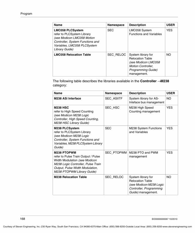
Program
Courtesy of St
The following table describes the libraries available in the Controller → M238 category:
LMC058 PLCSystemrefer to PLCSystem Library (see Modicon LMC058 Motion Controller, System Functions and Variables, LMC058 PLCSystem Library Guide)
SEC LMC058 System Functions and Variables
YES
LMC058 Relocation Table SEC_RELOC System library for Relocation Table (see Modicon LMC058 Motion Controller, Programming Guide) management.
NO
Name Namespace Description USER
M238 ASi Interface SEC_ASIITF System library for AS-Inteface bus management
NO
M238 HSCrefer to High Speed Counting (see Modicon M238 Logic Controller, High Speed Counting, M238 HSC Library Guide)
SEC_HSC M238 High Speed Counting management
YES
M238 PLCSystemrefer to PLCSystem Library (see Modicon M238 Logic Controller, System Functions and Variables, M238 PLCSystem Library Guide)
SEC M238 System Functions and Variables
YES
M238 PTOPWMrefer to Pulse Train Output / Pulse Width Modulation (see Modicon M238 Logic Controller, Pulse Train Output, Pulse Width Modulation, M238 PTOPWM Library Guide)
SEC_PTOPWM M238 PTO and PWM management
YES
M238 Relocation Table SEC_RELOC System library for Relocation Table (see Modicon M238 Logic Controller, Programming Guide) management.
NO
Name Namespace Description USER
168 EIO0000000067 10/2010
even Engineering, Inc.-230 Ryan Way, South San Francisco, CA 94080-6370-Main Office: (650) 588-9200-Outside Local Area: (800) 258-9200-www.stevenengineering.com
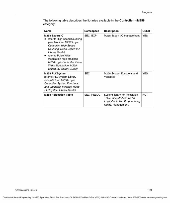
Program
Courtesy o
The following table describes the libraries available in the Controller → M258 category:
Name Namespace Description USER
M258 Expert IOrefer to High Speed Counting (see Modicon M258 Logic Controller, High Speed Counting, M258 Expert I/O Library Guide)refer to Pulse Width Modulation (see Modicon M258 Logic Controller, Pulse Width Modulation, M258 Expert I/O Library Guide)
SEC_EXP M258 Expert I/O management YES
M258 PLCSystemrefer to PLCSystem Library (see Modicon M258 Logic Controller, System Functions and Variables, Modicon M258 PLCSystem Library Guide)
SEC M258 System Functions and Variables
YES
M258 Relocation Table SEC_RELOC System library for Relocation Table (see Modicon M258 Logic Controller, Programming Guide) management.
NO
EIO0000000067 10/2010 169
f Steven Engineering, Inc.-230 Ryan Way, South San Francisco, CA 94080-6370-Main Office: (650) 588-9200-Outside Local Area: (800) 258-9200-www.stevenengineering.com
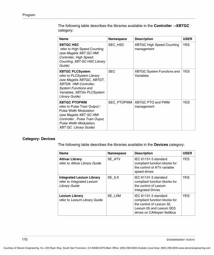
Program
Courtesy of St
The following table describes the libraries available in the Controller → XBTGC category:
Category: Devices
The following table describes the libraries available in the Devices category:
Name Namespace Description USER
XBTGC HSC refer to High Speed Counting (see Magelis XBT GC HMI Controller, High Speed Counting, XBT GC HSC Library Guide)
SEC_HSC XBTGC High Speed Counting management
YES
XBTGC PLCSystemrefer to PLCSystem Library (see Magelis XBTGC, XBTGT, XBTGK HMI Controller, System Functions and Variables, XBTGx PLCSystem Library Guide)
SEC XBTGC System Functions and Variables
YES
XBTGC PTOPWMrefer to Pulse Train Output / Pulse Width Modulation (see Magelis XBT GC HMI Controller , Pulse Train Ouput, Pulse Width Modulation, XBT GC Library Guide)
SEC_PTOPWM XBTGC PTO and PWM management
YES
Name Namespace Description USER
Altivar Libraryrefer to Altivar Library Guide
SE_ATV IEC 61131-3 standard compliant function blocks for the control of ATV variable speed drives
YES
Integrated Lexium Libraryrefer to Integrated Lexium Library Guide
SE_ILX IEC 61131-3 standard compliant function blocks for the control of Lexium Integrated Drives
YES
Lexium Libraryrefer to Lexium Library Guide
SE_LXM IEC 61131-3 standard compliant function blocks for the control of Lexium 32, Lexium 05 and Lexium SD3 drives on CANopen fieldbus
YES
170 EIO0000000067 10/2010
even Engineering, Inc.-230 Ryan Way, South San Francisco, CA 94080-6370-Main Office: (650) 588-9200-Outside Local Area: (800) 258-9200-www.stevenengineering.com
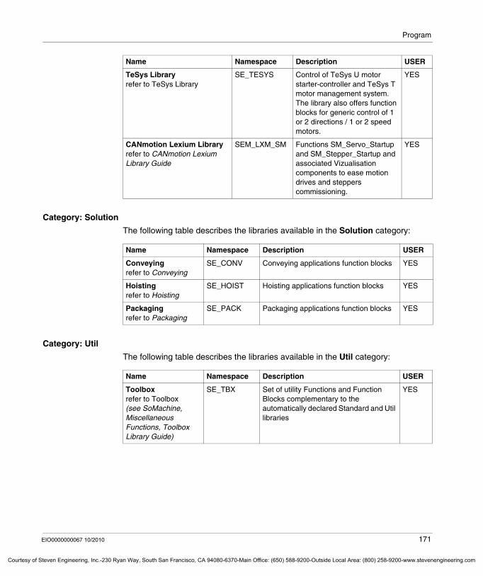
Program
Courtesy o
Category: Solution
The following table describes the libraries available in the Solution category:
Category: Util
The following table describes the libraries available in the Util category:
TeSys Libraryrefer to TeSys Library
SE_TESYS Control of TeSys U motor starter-controller and TeSys T motor management system.The library also offers function blocks for generic control of 1 or 2 directions / 1 or 2 speed motors.
YES
CANmotion Lexium Libraryrefer to CANmotion Lexium Library Guide
SEM_LXM_SM Functions SM_Servo_Startup and SM_Stepper_Startup and associated Vizualisation components to ease motion drives and steppers commissioning.
YES
Name Namespace Description USER
Name Namespace Description USER
Conveyingrefer to Conveying
SE_CONV Conveying applications function blocks YES
Hoistingrefer to Hoisting
SE_HOIST Hoisting applications function blocks YES
Packagingrefer to Packaging
SE_PACK Packaging applications function blocks YES
Name Namespace Description USER
Toolboxrefer to Toolbox (see SoMachine, Miscellaneous Functions, Toolbox Library Guide)
SE_TBX Set of utility Functions and Function Blocks complementary to the automatically declared Standard and Util libraries
YES
EIO0000000067 10/2010 171
f Steven Engineering, Inc.-230 Ryan Way, South San Francisco, CA 94080-6370-Main Office: (650) 588-9200-Outside Local Area: (800) 258-9200-www.stevenengineering.com
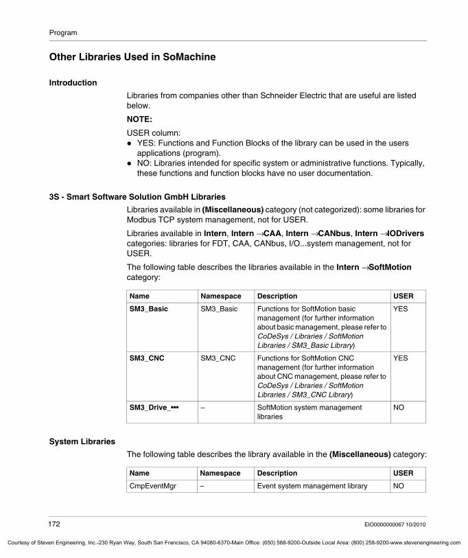
Program
Courtesy of St
Other Libraries Used in SoMachine
Introduction
Libraries from companies other than Schneider Electric that are useful are listed below.
NOTE:
USER column:YES: Functions and Function Blocks of the library can be used in the users applications (program).NO: Libraries intended for specific system or administrative functions. Typically, these functions and function blocks have no user documentation.
3S - Smart Software Solution GmbH Libraries
Libraries available in (Miscellaneous) category (not categorized): some libraries for Modbus TCP system management, not for USER.
Libraries available in Intern, Intern → CAA, Intern → CANbus, Intern → IODrivers categories: libraries for FDT, CAA, CANbus, I/O...system management, not for USER.
The following table describes the libraries available in the Intern → SoftMotion category:
System Libraries
The following table describes the library available in the (Miscellaneous) category:
Name Namespace Description USER
SM3_Basic SM3_Basic Functions for SoftMotion basic management (for further information about basic management, please refer to CoDeSys / Libraries / SoftMotion Libraries / SM3_Basic Library)
YES
SM3_CNC SM3_CNC Functions for SoftMotion CNC management (for further information about CNC management, please refer to CoDeSys / Libraries / SoftMotion Libraries / SM3_CNC Library)
YES
SM3_Drive_••• – SoftMotion system management libraries
NO
Name Namespace Description USER
CmpEventMgr – Event system management library NO
172 EIO0000000067 10/2010
even Engineering, Inc.-230 Ryan Way, South San Francisco, CA 94080-6370-Main Office: (650) 588-9200-Outside Local Area: (800) 258-9200-www.stevenengineering.com
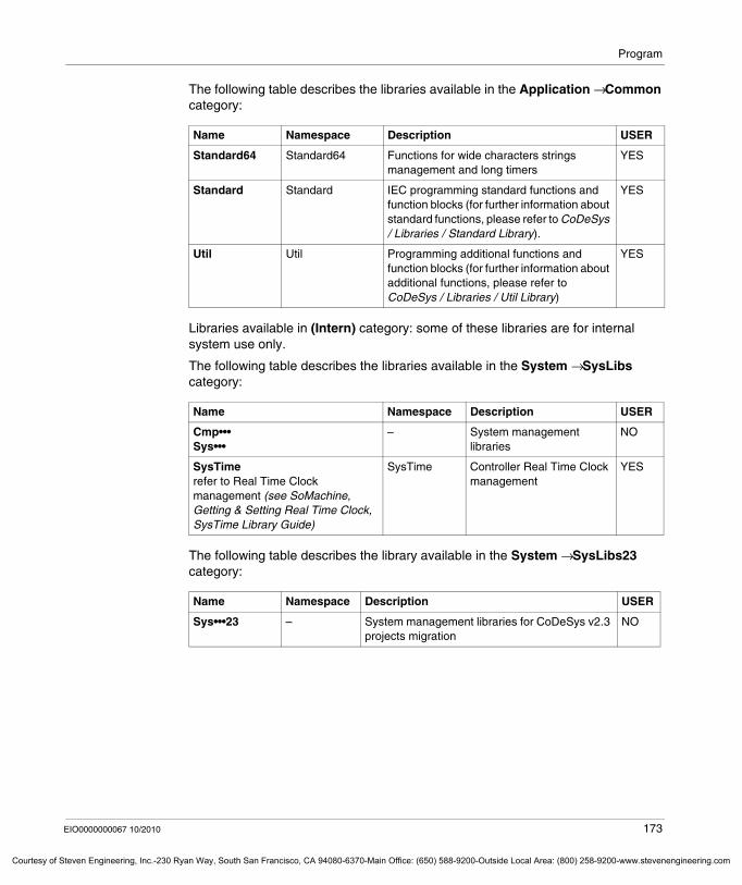
Program
Courtesy o
The following table describes the libraries available in the Application → Common category:
Libraries available in (Intern) category: some of these libraries are for internal system use only.
The following table describes the libraries available in the System → SysLibs category:
The following table describes the library available in the System → SysLibs23 category:
Name Namespace Description USER
Standard64 Standard64 Functions for wide characters strings management and long timers
YES
Standard Standard IEC programming standard functions and function blocks (for further information about standard functions, please refer to CoDeSys / Libraries / Standard Library).
YES
Util Util Programming additional functions and function blocks (for further information about additional functions, please refer to CoDeSys / Libraries / Util Library)
YES
Name Namespace Description USER
Cmp•••Sys•••
– System management libraries
NO
SysTimerefer to Real Time Clock management (see SoMachine, Getting & Setting Real Time Clock, SysTime Library Guide)
SysTime Controller Real Time Clock management
YES
Name Namespace Description USER
Sys•••23 – System management libraries for CoDeSys v2.3 projects migration
NO
EIO0000000067 10/2010 173
f Steven Engineering, Inc.-230 Ryan Way, South San Francisco, CA 94080-6370-Main Office: (650) 588-9200-Outside Local Area: (800) 258-9200-www.stevenengineering.com
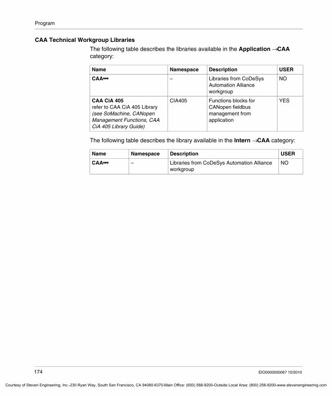
Program
Courtesy of St
CAA Technical Workgroup Libraries
The following table describes the libraries available in the Application → CAA category:
The following table describes the library available in the Intern → CAA category:
Name Namespace Description USER
CAA••• – Libraries from CoDeSys Automation Alliance workgroup
NO
CAA CiA 405refer to CAA CiA 405 Library (see SoMachine, CANopen Management Functions, CAA CiA 405 Library Guide)
CIA405 Functions blocks for CANopen fieldbus management from application
YES
Name Namespace Description USER
CAA••• – Libraries from CoDeSys Automation Alliance workgroup
NO
174 EIO0000000067 10/2010
even Engineering, Inc.-230 Ryan Way, South San Francisco, CA 94080-6370-Main Office: (650) 588-9200-Outside Local Area: (800) 258-9200-www.stevenengineering.com
Program
Courtesy o
Creating Your Own Libraries
Overview
SoMachine provides the possibility to save a SoMachine project file (<projectname>.project) as a library file (<projectname>.library) and vice-versa. The library file only includes the objects managed in the POUs window.
Procedure
To create your own library project via the Program tab, proceed as follows:
NOTE: For more detailed information refer to the CoDeSys part of the online help.
To check the syntax and find your potential errors, use the command Check all Pool objects in the menu build, before using Save the project as a compiled library or Save project and install library into library repository.
It is best to first code your logic in a regular project application and use the tools available to debug your logic, such as breakpoints and inspection of data values. Once a library is compiled, the logic can not be viewed or modified.
Step Action
1 The SoMachine Program tab provides 2 different ways to create a new library project:
Either by using the File → New menu and selecting the Empty Library project template from the Categories → Basic Controllers.Or by using the File → Save project as... menu and selecting from the Save as type list box the Library file type.
2 Fill in the mandatory fields in the File Project → Project information.
3 In your library project create your:functions and function blocksdatatype definitionsglobal variablesvisualization objectslibraries
NOTE: Only the objects managed in the POUs window will be considered for a library project.
NOTE: If you add standard SoMachine libraries to your own library, always use placeholders to reference them. For details on referencing libraries by placeholders refer to the Adding Libraries chapter (see page 137).
4 Execute the command File → Save project and install library into library repository.Result: Your library is now installed on your PC and can be added to any project on your PC using the Library manager.
EIO0000000067 10/2010 175
f Steven Engineering, Inc.-230 Ryan Way, South San Francisco, CA 94080-6370-Main Office: (650) 588-9200-Outside Local Area: (800) 258-9200-www.stevenengineering.com
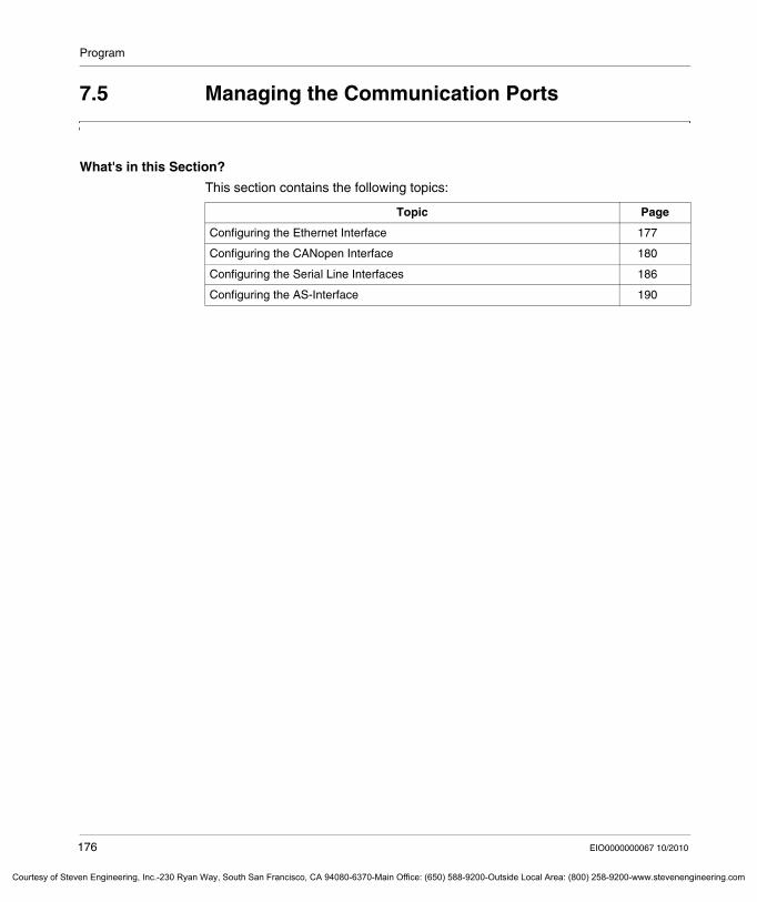
Program
Courtesy of St
7.5 Managing the Communication Ports
What's in this Section?
This section contains the following topics:
Topic Page
Configuring the Ethernet Interface 177
Configuring the CANopen Interface 180
Configuring the Serial Line Interfaces 186
Configuring the AS-Interface 190
176 EIO0000000067 10/2010
even Engineering, Inc.-230 Ryan Way, South San Francisco, CA 94080-6370-Main Office: (650) 588-9200-Outside Local Area: (800) 258-9200-www.stevenengineering.com
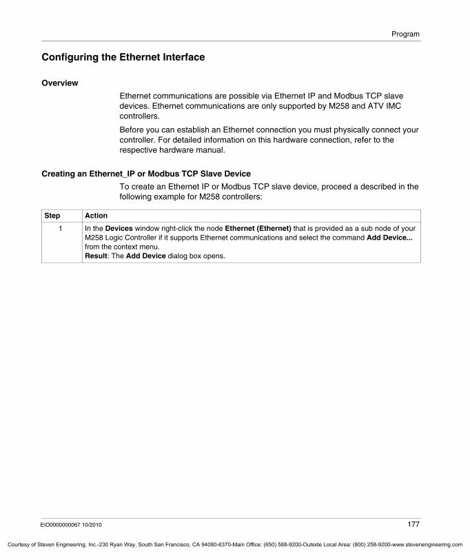
Program
Courtesy o
Configuring the Ethernet Interface
Overview
Ethernet communications are possible via Ethernet IP and Modbus TCP slave devices. Ethernet communications are only supported by M258 and ATV IMC controllers.
Before you can establish an Ethernet connection you must physically connect your controller. For detailed information on this hardware connection, refer to the respective hardware manual.
Creating an Ethernet_IP or Modbus TCP Slave Device
To create an Ethernet IP or Modbus TCP slave device, proceed a described in the following example for M258 controllers:
Step Action
1 In the Devices window right-click the node Ethernet (Ethernet) that is provided as a sub node of your M258 Logic Controller if it supports Ethernet communications and select the command Add Device... from the context menu.Result: The Add Device dialog box opens.
EIO0000000067 10/2010 177
f Steven Engineering, Inc.-230 Ryan Way, South San Francisco, CA 94080-6370-Main Office: (650) 588-9200-Outside Local Area: (800) 258-9200-www.stevenengineering.com
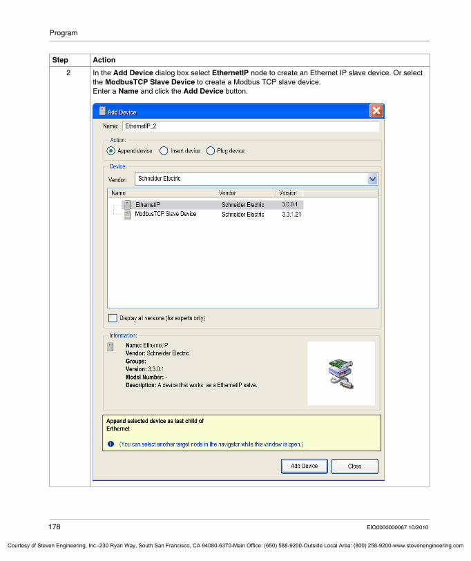
Program
Courtesy of St
2 In the Add Device dialog box select EthernetIP node to create an Ethernet IP slave device. Or select the ModbusTCP Slave Device to create a Modbus TCP slave device.Enter a Name and click the Add Device button.
Step Action
178 EIO0000000067 10/2010
even Engineering, Inc.-230 Ryan Way, South San Francisco, CA 94080-6370-Main Office: (650) 588-9200-Outside Local Area: (800) 258-9200-www.stevenengineering.com
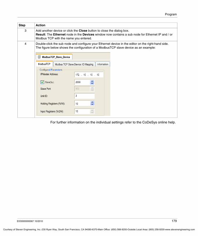
Program
Courtesy o
For further information on the individual settings refer to the CoDeSys online help.
3 Add another device or click the Close button to close the dialog box.Result: The Ethernet node in the Devices window now contains a sub node for Ethernet IP and / or Modbus TCP with the name you entered.
4 Double-click the sub node and configure your Ethernet device in the editor on the right-hand side. The figure below shows the configuration of a ModbusTCP slave device as an example:
Step Action
EIO0000000067 10/2010 179
f Steven Engineering, Inc.-230 Ryan Way, South San Francisco, CA 94080-6370-Main Office: (650) 588-9200-Outside Local Area: (800) 258-9200-www.stevenengineering.com
Program
Courtesy of St
Configuring the CANopen Interface
Overview
For CANopen communications you must first define the transmission rate and configure a CANopen master. The following paragraphs describe how to define the transmission rate in the CANopen configuration dialog box and to create and configure the CANopen Manager that serves as CANopen master using an M238 Logic Controller as an example.
Before you can establish a CANopen connection you must physically connect your CANopen devices to your controller. For detailed information on this hardware connection, refer to the hardware manual of your controller.
180 EIO0000000067 10/2010
even Engineering, Inc.-230 Ryan Way, South San Francisco, CA 94080-6370-Main Office: (650) 588-9200-Outside Local Area: (800) 258-9200-www.stevenengineering.com
Program
Courtesy o
Configuring the Transmission Rate
To configure the transmission rate for CANopen communications, proceed as follows:
Step Action
1 In the Devices window double-click the entry CAN that is provided as a subitem of your M238 Logic Controller if it is equipped with a CANopen interface.
Result: The tabbed configuration dialog box for CANopen communications will be displayed on the right-hand side.
2 In the CANbus tab configure the transmission rate:
From the Baudrate list select the transmission rate of your CANopen connection, by default 250,000 bit/s.To inhibit access to the NMT commands and Service data object (SDO) parameters, that are provided in the Status tab of each device when you are logged in, while the controller is in RUN mode, select the Online Bus Access check box.
EIO0000000067 10/2010 181
f Steven Engineering, Inc.-230 Ryan Way, South San Francisco, CA 94080-6370-Main Office: (650) 588-9200-Outside Local Area: (800) 258-9200-www.stevenengineering.com
Program
Courtesy of St
Creating and Configuring the CANopen Manager
To create and configure the CANopen Manager, that serves as CANopen master and that is required for CANopen communications, proceed as follows:
Step Action
1 In the Devices window right-click the node CAN that is provided as a sub node of your M238 Logic Controller and select the command Add Device... from the context menu:
Result: The Add Device dialog box opens.
182 EIO0000000067 10/2010
even Engineering, Inc.-230 Ryan Way, South San Francisco, CA 94080-6370-Main Office: (650) 588-9200-Outside Local Area: (800) 258-9200-www.stevenengineering.com
Program
Courtesy o
2 In the Add Device dialog box select the CANopen_Manager.Adapt the default Name, if required, and click the Add Device button:
Step Action
EIO0000000067 10/2010 183
f Steven Engineering, Inc.-230 Ryan Way, South San Francisco, CA 94080-6370-Main Office: (650) 588-9200-Outside Local Area: (800) 258-9200-www.stevenengineering.com
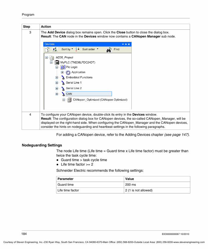
Program
Courtesy of St
For adding a CANopen device, refer to the Adding Devices chapter (see page 147).
Nodeguarding Settings
The node Life time (Life time = Guard time x Life time factor) must be greater than twice the task cycle time:
Guard time > task cycle timeLife time factor >= 2
Schneider Electric recommends the following settings:
3 The Add Device dialog box remains open. Click the Close button to close the dialog box.Result: The CAN node in the Devices window now contains a CANopen Manager sub node.
4 To configure your CANopen device, double-click its entry in the Devices window.Result: The configuration dialog box for CANopen devices, the so-called CANopen_Manager, will be displayed on the right-hand side. When configuring the CANopen_Manager and the CANopen devices, consider the hints on nodeguarding and heartbeat settings in the following paragraphs.
Step Action
Parameter Value
Guard time 200 ms
Life time factor 2 (1 is not allowed)
184 EIO0000000067 10/2010
even Engineering, Inc.-230 Ryan Way, South San Francisco, CA 94080-6370-Main Office: (650) 588-9200-Outside Local Area: (800) 258-9200-www.stevenengineering.com
Program
Courtesy o
Heartbeat Settings
The CANopen_Manager heartbeat producer time must be equal to or greater than the task cycle. To avoid jitter, choose a producer time that is a multiple of the task cycle:
CANopen_Manager Producer time >= Task cycle time
The Node heartbeat consumer time must be greater than twice the CANopen_Manager heartbeat producer time:
Node Consumer time >= 2.5 x CANopen_Manager Producer time
The Node heartbeat producer time must be equal to or greater than the task cycle:Node Producer time >= Task cycle time
Schneider Electric recommends the following settings:
NOTE: Nodeguarding can be activated (configuration in slaves) only if heartbeat producer AND consumer are de-activated.
Parameter Value
CANopen_Manager Producer time 200 ms
Node Consumer time 500 ms
Node Producer time 200 ms
EIO0000000067 10/2010 185
f Steven Engineering, Inc.-230 Ryan Way, South San Francisco, CA 94080-6370-Main Office: (650) 588-9200-Outside Local Area: (800) 258-9200-www.stevenengineering.com
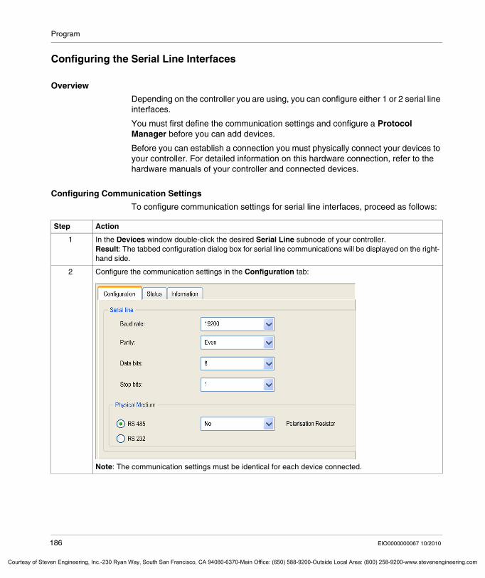
Program
Courtesy of St
Configuring the Serial Line Interfaces
Overview
Depending on the controller you are using, you can configure either 1 or 2 serial line interfaces.
You must first define the communication settings and configure a Protocol Manager before you can add devices.
Before you can establish a connection you must physically connect your devices to your controller. For detailed information on this hardware connection, refer to the hardware manuals of your controller and connected devices.
Configuring Communication Settings
To configure communication settings for serial line interfaces, proceed as follows:
Step Action
1 In the Devices window double-click the desired Serial Line subnode of your controller.Result: The tabbed configuration dialog box for serial line communications will be displayed on the right-hand side.
2 Configure the communication settings in the Configuration tab:
Note: The communication settings must be identical for each device connected.
186 EIO0000000067 10/2010
even Engineering, Inc.-230 Ryan Way, South San Francisco, CA 94080-6370-Main Office: (650) 588-9200-Outside Local Area: (800) 258-9200-www.stevenengineering.com
Program
Courtesy o
Protocol Managers
For each serial line interface, one of the following Protocol Managers is required:
There is one Protocol Manager preconfigured for each serial line interface, but it can be removed and configured according to your individual requirements.
Protocol Manager Description
ASCII Manager Used to transmit and / or receive data with a simple device.
Modbus Manager Used for Modbus RTU or ASCII protocol in master or slave mode.
Modbus IOScanner Modbus RTU or ASCII protocol manager used to define implicite exchanges (I/O scanning) with Modbus slave devices.
SoMachine Network Manager Must be used if you want to connect an XBTGT, XBTGK or XBTGH HMI through SoMachine protocol offering transparent exchange of data and multiple download capability (download of controller and HMI applications through 1 unique connection PC-controller or PC-HMI).
EIO0000000067 10/2010 187
f Steven Engineering, Inc.-230 Ryan Way, South San Francisco, CA 94080-6370-Main Office: (650) 588-9200-Outside Local Area: (800) 258-9200-www.stevenengineering.com
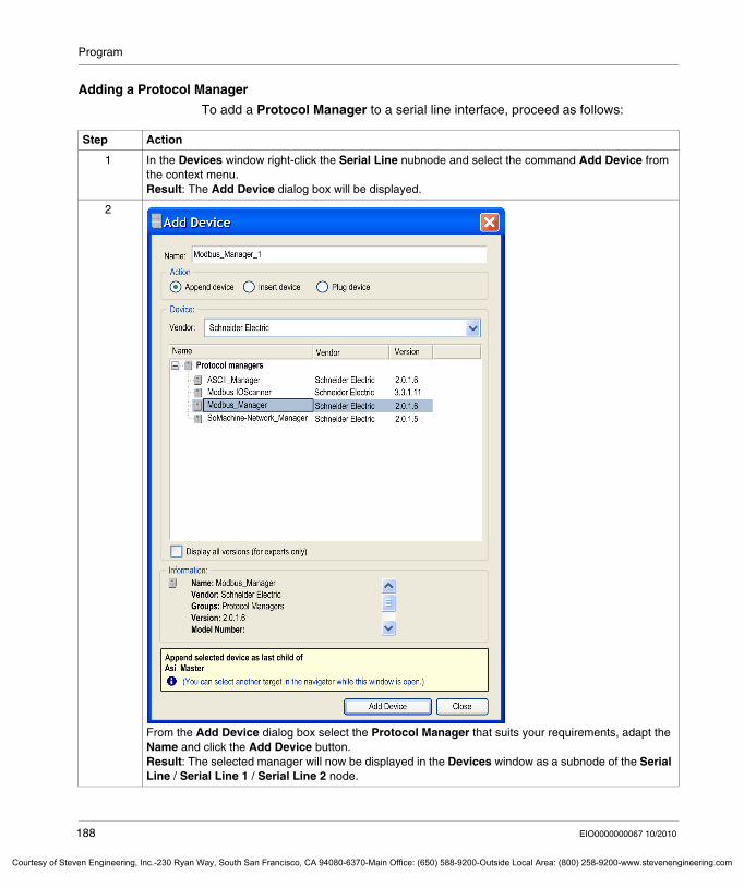
Program
Courtesy of St
Adding a Protocol Manager
To add a Protocol Manager to a serial line interface, proceed as follows:
Step Action
1 In the Devices window right-click the Serial Line nubnode and select the command Add Device from the context menu.Result: The Add Device dialog box will be displayed.
2
From the Add Device dialog box select the Protocol Manager that suits your requirements, adapt the Name and click the Add Device button.Result: The selected manager will now be displayed in the Devices window as a subnode of the Serial Line / Serial Line 1 / Serial Line 2 node.
188 EIO0000000067 10/2010
even Engineering, Inc.-230 Ryan Way, South San Francisco, CA 94080-6370-Main Office: (650) 588-9200-Outside Local Area: (800) 258-9200-www.stevenengineering.com
Program
Courtesy o
You can now add your devices as described in the Adding Devices to a Communication Manager chapter (see page 154).
3 To configure the Protocol Manager, double-click its entry in the Devices window.Result: The tabbed configuration dialog box for the selected Protocol Manager will be displayed on the right-hand side. For further information on configuring the individual Protocol Managers, refer to the Programming Guide of your controller or to the CoDeSys part of the online help.
Step Action
EIO0000000067 10/2010 189
f Steven Engineering, Inc.-230 Ryan Way, South San Francisco, CA 94080-6370-Main Office: (650) 588-9200-Outside Local Area: (800) 258-9200-www.stevenengineering.com
Program
Courtesy of St
Configuring the AS-Interface
Overview
AS-Interface communications are only supported by M238 controllers.
To establish AS-Interface communications, you first have to add an AS-Interface Master Module. Then you can add AS-Interface slave modules.
Adding and Configuring the AS-Interface Master Module
To add the AS-Interface Master Module TWDNOI10M3, proceed as follows:
Step Action
1 In the Devices window right-click the node of your M238 controller (for example TM238LFDC24DT) and select the command Add Device from the context menu.Result: The Add Device dialog box will be displayed.
190 EIO0000000067 10/2010
even Engineering, Inc.-230 Ryan Way, South San Francisco, CA 94080-6370-Main Office: (650) 588-9200-Outside Local Area: (800) 258-9200-www.stevenengineering.com
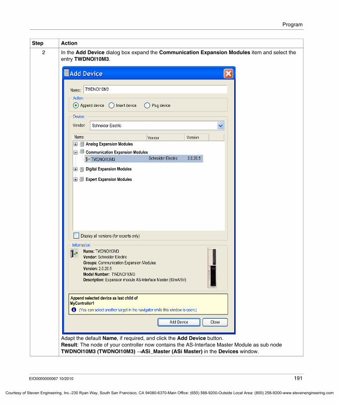
Program
Courtesy o
2 In the Add Device dialog box expand the Communication Expansion Modules item and select the entry TWDNOI10M3.
Adapt the default Name, if required, and click the Add Device button.Result: The node of your controller now contains the AS-Interface Master Module as sub node TWDNOI10M3 (TWDNOI10M3) → ASi_Master (ASi Master) in the Devices window.
Step Action
EIO0000000067 10/2010 191
f Steven Engineering, Inc.-230 Ryan Way, South San Francisco, CA 94080-6370-Main Office: (650) 588-9200-Outside Local Area: (800) 258-9200-www.stevenengineering.com
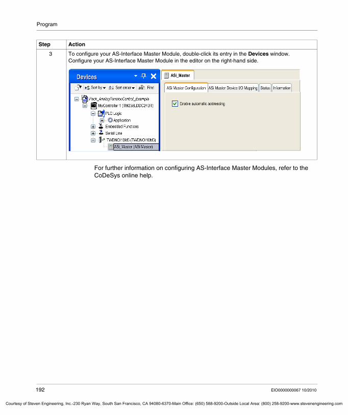
Program
Courtesy of St
For further information on configuring AS-Interface Master Modules, refer to the CoDeSys online help.
3 To configure your AS-Interface Master Module, double-click its entry in the Devices window.Configure your AS-Interface Master Module in the editor on the right-hand side.
Step Action
192 EIO0000000067 10/2010
even Engineering, Inc.-230 Ryan Way, South San Francisco, CA 94080-6370-Main Office: (650) 588-9200-Outside Local Area: (800) 258-9200-www.stevenengineering.com
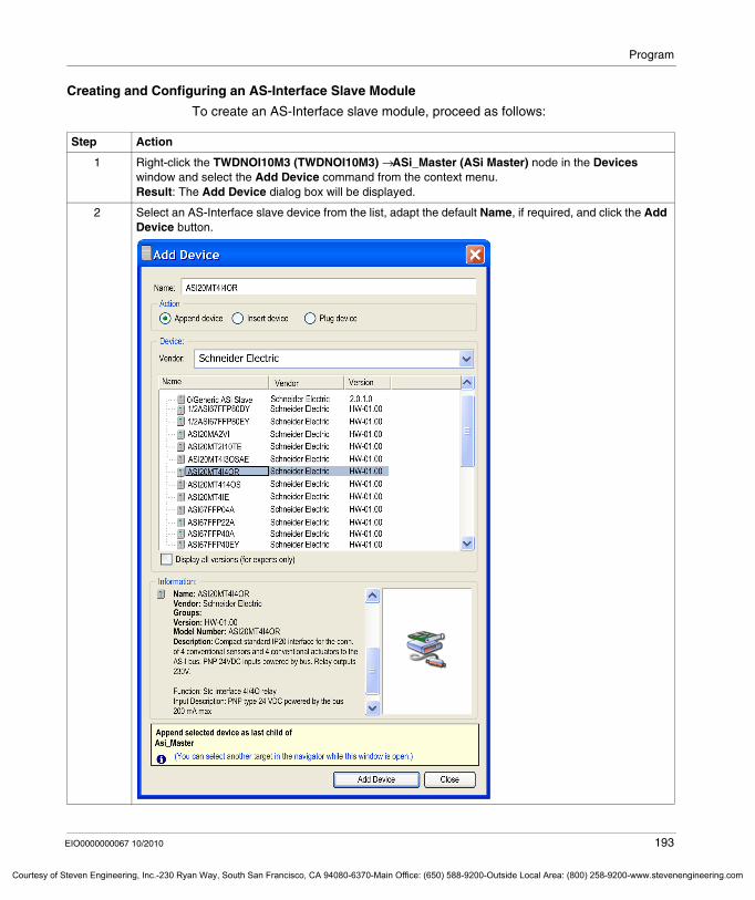
Program
Courtesy o
Creating and Configuring an AS-Interface Slave Module
To create an AS-Interface slave module, proceed as follows:
Step Action
1 Right-click the TWDNOI10M3 (TWDNOI10M3) → ASi_Master (ASi Master) node in the Devices window and select the Add Device command from the context menu.Result: The Add Device dialog box will be displayed.
2 Select an AS-Interface slave device from the list, adapt the default Name, if required, and click the Add Device button.
EIO0000000067 10/2010 193
f Steven Engineering, Inc.-230 Ryan Way, South San Francisco, CA 94080-6370-Main Office: (650) 588-9200-Outside Local Area: (800) 258-9200-www.stevenengineering.com
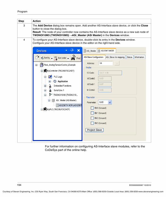
Program
Courtesy of St
For further information on configuring AS-Interface slave modules, refer to the CoDeSys part of the online help.
3 The Add Device dialog box remains open. Add another AS-Interface slave device, or click the Close button to close the dialog box.Result: The node of your controller now contains the AS-Interface slave device as a new sub node of TWDNOI10M3 (TWDNOI10M3) → ASi_Master (ASi Master) in the Devices window.
4 To configure your AS-Interface slave device, double-click its entry in the Devices window.Configure your AS-Interface slave device in the editor on the right-hand side.
Step Action
194 EIO0000000067 10/2010
even Engineering, Inc.-230 Ryan Way, South San Francisco, CA 94080-6370-Main Office: (650) 588-9200-Outside Local Area: (800) 258-9200-www.stevenengineering.com
Program
Courtesy o
7.6 SoMachine Commands
What's in this Section?
This section contains the following topics:
Topic Page
SoMachine Commands Providing Single Access to Your Machine 196
Description of the Build All Command 197
Description of the Create Boot Application Command 198
Description of the USB Mass Storage Command 199
Description of the Import / Export Vijeo-Designer Project Commands 201
EIO0000000067 10/2010 195
f Steven Engineering, Inc.-230 Ryan Way, South San Francisco, CA 94080-6370-Main Office: (650) 588-9200-Outside Local Area: (800) 258-9200-www.stevenengineering.com
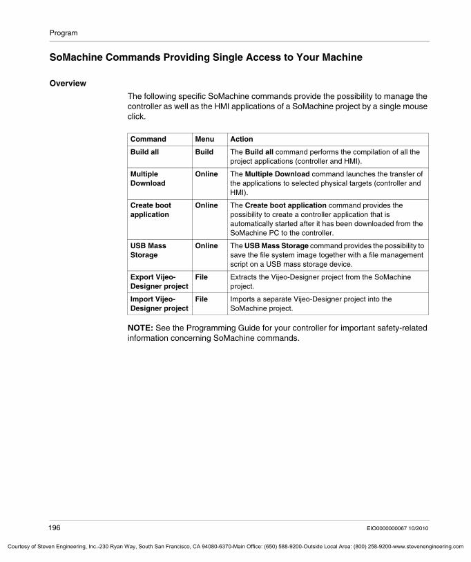
Program
Courtesy of St
SoMachine Commands Providing Single Access to Your Machine
Overview
The following specific SoMachine commands provide the possibility to manage the controller as well as the HMI applications of a SoMachine project by a single mouse click.
NOTE: See the Programming Guide for your controller for important safety-related information concerning SoMachine commands.
Command Menu Action
Build all Build The Build all command performs the compilation of all the project applications (controller and HMI).
Multiple Download
Online The Multiple Download command launches the transfer of the applications to selected physical targets (controller and HMI).
Create boot application
Online The Create boot application command provides the possibility to create a controller application that is automatically started after it has been downloaded from the SoMachine PC to the controller.
USB Mass Storage
Online The USB Mass Storage command provides the possibility to save the file system image together with a file management script on a USB mass storage device.
Export Vijeo-Designer project
File Extracts the Vijeo-Designer project from the SoMachine project.
Import Vijeo-Designer project
File Imports a separate Vijeo-Designer project into the SoMachine project.
196 EIO0000000067 10/2010
even Engineering, Inc.-230 Ryan Way, South San Francisco, CA 94080-6370-Main Office: (650) 588-9200-Outside Local Area: (800) 258-9200-www.stevenengineering.com
Program
Courtesy o
Description of the Build All Command
Overview
The Build all command performs 2 operations:It compiles those controller applications that are located under the item PLC Logic in the Devices tree.It builds all HMI target applications.
Procedure
Execute the Build all command as follows:
Step Action
1 From the Build menu select the command Build all.Result: The applications are compiled and the HMI target applications are built. This is indicated in the Messages window of SoMachine.
2 In the Messages window of SoMachine select Build from the list in the upper left side of the window to see the results of the individual compile processes.
3 To display a summary of the messages that occurred during the execution of the Build all command, select Vijeo-Designer from the list in the upper left side of the window.
4 To verify the messages you can start Vijeo-Designer directly by double-clicking the Vijeo-Designer message in the Messages window.
EIO0000000067 10/2010 197
f Steven Engineering, Inc.-230 Ryan Way, South San Francisco, CA 94080-6370-Main Office: (650) 588-9200-Outside Local Area: (800) 258-9200-www.stevenengineering.com
Program
Courtesy of St
Description of the Create Boot Application Command
Overview
The Create boot application command in the Online menu provides the possibility to create a controller application that is automatically started after it has been downloaded from the SoMachine PC to the controller.
NOTE: This function is restricted to controller applications. HMI applications do not support this feature.
Procedure
To create a boot application for your application, proceed as follows:
Step Action
1 In the Devices view select the Application node of the application you want to create a boot application for.
2 From the Online menu select the command Create boot application.Result: SoMachine will automatically build the application. If errors are detected during the build process, they will be issued in the Messages pane. If the build process is executed successfully, a Save as dialog box will be displayed.
3 In the Save as dialog box navigate to the folder where you want to save the boot application and click the Save button.Result: A message box will be displayed asking you whether you want to overwrite the reference context of the last download.
4 Click Yes and the following files will be saved to the specified folder:Myapplication.AppMyapplication.crc
198 EIO0000000067 10/2010
even Engineering, Inc.-230 Ryan Way, South San Francisco, CA 94080-6370-Main Office: (650) 588-9200-Outside Local Area: (800) 258-9200-www.stevenengineering.com
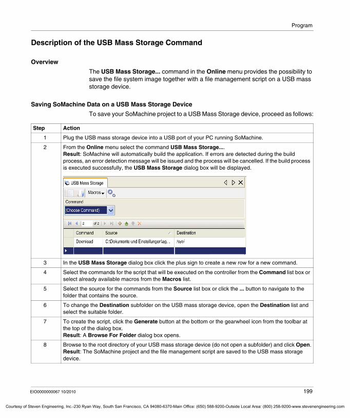
Program
Courtesy o
Description of the USB Mass Storage Command
Overview
The USB Mass Storage... command in the Online menu provides the possibility to save the file system image together with a file management script on a USB mass storage device.
Saving SoMachine Data on a USB Mass Storage Device
To save your SoMachine project to a USB Mass Storage device, proceed as follows:
Step Action
1 Plug the USB mass storage device into a USB port of your PC running SoMachine.
2 From the Online menu select the command USB Mass Storage....Result: SoMachine will automatically build the application. If errors are detected during the build process, an error detection message will be issued and the process will be cancelled. If the build process is executed successfully, the USB Mass Storage dialog box will be displayed.
3 In the USB Mass Storage dialog box click the plus sign to create a new row for a new command.
4 Select the commands for the script that will be executed on the controller from the Command list box or select already available macros from the Macros list.
5 Select the source for the commands from the Source list box or click the ... button to navigate to the folder that contains the source.
6 To change the Destination subfolder on the USB mass storage device, open the Destination list and select the suitable folder.
7 To create the script, click the Generate button at the bottom or the gearwheel icon from the toolbar at the top of the dialog box.Result: A Browse For Folder dialog box opens.
8 Browse to the root directory of your USB mass storage device (do not open a subfolder) and click Open.Result: The SoMachine project and the file management script are saved to the USB mass storage device.
EIO0000000067 10/2010 199
f Steven Engineering, Inc.-230 Ryan Way, South San Francisco, CA 94080-6370-Main Office: (650) 588-9200-Outside Local Area: (800) 258-9200-www.stevenengineering.com
Program
Courtesy of St
Installing the SoMachine Project on a Controller
To install the SoMachine project on a controller, merely plug the USB mass storage device into a USB port of the controller.
The script on the USB device will be executed automatically which is indicated by the LEDs of the controller as follows:
Log File
A log file is automatically saved in the folder of the script file.
It records every execution of the script file with header information (date, time, and machine information) and the result (successful, or not successful like: source file not available, incorrect destination, incorrect command, destination full).
Any new information is added to the file, information will not be overwritten.
Action Performed LED Indication Comment
USB mass storage device is plugged into the controller.
red LED is on The red LED is on until the communication to the USB mass storage has been established.
Script file is executed. green LED is blinking –
Script file execution has been completed successfully.
green LED is on You can remove the USB mass storage device.
The script file could not be executed successfully.
red LED is on See the log file on the USB mass storage device for reasons why the script file could not be executed successfully.
200 EIO0000000067 10/2010
even Engineering, Inc.-230 Ryan Way, South San Francisco, CA 94080-6370-Main Office: (650) 588-9200-Outside Local Area: (800) 258-9200-www.stevenengineering.com
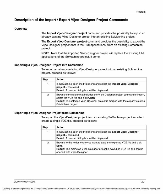
Program
Courtesy o
Description of the Import / Export Vijeo-Designer Project Commands
Overview
The Import Vijeo-Designer project command provides the possibility to import an already existing Vijeo-Designer project into an existing SoMachine project.
The Export Vijeo-Designer project command provides the possibility to export the Vijeo-Designer project (that is the HMI applications) from an existing SoMachine project.
NOTE: Note that the imported Vijeo-Designer project will replace the existing HMI applications of the SoMachine project, if some.
Importing a Vijeo-Designer Project into SoMachine
To import an already existing Vijeo-Designer project into an existing SoMachine project, proceed as follows:
Exporting a Vijeo-Designer Project from SoMachine
To export the Vijeo-Designer project from an existing SoMachine project in order to create a single VDZ file, proceed as follows:
Step Action
1 In SoMachine open the File menu and select the Import Vijeo-Designer project... command.Result: A browse dialog box will be displayed.
2 Browse to the folder that includes the Vijeo-Designer project you want to import, select the VDZ file and click Open.Result: The selected Vijeo-Designer project is merged with the already existing SoMachine project.
Step Action
1 In SoMachine open the File menu and select the Export Vijeo-Designer project... command.Result: A browse dialog box will be displayed.
2 Browse to the folder where you want to save the exported VDZ file and click Save.Result: The extracted Vijeo-Designer project is saved as VDZ file and can be opened with Vijeo-Designer.
EIO0000000067 10/2010 201
f Steven Engineering, Inc.-230 Ryan Way, South San Francisco, CA 94080-6370-Main Office: (650) 588-9200-Outside Local Area: (800) 258-9200-www.stevenengineering.com
Program
Courtesy of St
7.7 SoMachine Controller-HMI Data Exchange
What's in this Section?
This section contains the following topics:
Topic Page
SoMachine Single Variable Definition 203
Publishing Variables in the Controller Part 207
Selecting Variables in the HMI Part 208
Publishing Variables in the HMI Part 209
Parametrization of the Physical Media 211
202 EIO0000000067 10/2010
even Engineering, Inc.-230 Ryan Way, South San Francisco, CA 94080-6370-Main Office: (650) 588-9200-Outside Local Area: (800) 258-9200-www.stevenengineering.com
Program
Courtesy o
SoMachine Single Variable Definition
Overview
Sharing variables between a controller and the HMI is very simple in SoMachine. By publishing the variable(s) in SoMachine they will automatically be available for use in the Vijeo-Designer HMI application.
For variable exchange with the SoMachine protocol, perform the following steps:Create variables in the controller part.Publish the variables by defining them as Symbols in the controller part. They are now available in the HMI part as SoMachine variables.Configure the physical connection (automatically setup by SoMachine).
NOTE: This step is not necessary for XBTGC controllers because they may communicate with their own control variables or those on other controllers.
Disabling Automatic Symbol Export to Vijeo-Designer
By default, SoMachine automatically exports those variables defined as Symbols to the Vijeo-Designer HMI application.
Once symbols have been transfered to Vijeo-Designer, it is usually not necessary to make the transfer every time you call Vijeo-Designer. If you later add or modify symbols in your SoMachine application after having initially transfered the symbols, you can transfer symbols to Vijeo-Designer manually at will. To save time when you open Vijeo-Designer, you can disable the automatic transfer of symbols as follows:
Step Action
1 In the general functions menu (see page 25) select Preferences and click the Options button.Result: The Options dialog box will be displayed.
2 Select the entry Vijeo-Designer from the list on the left-hand side.
EIO0000000067 10/2010 203
f Steven Engineering, Inc.-230 Ryan Way, South San Francisco, CA 94080-6370-Main Office: (650) 588-9200-Outside Local Area: (800) 258-9200-www.stevenengineering.com
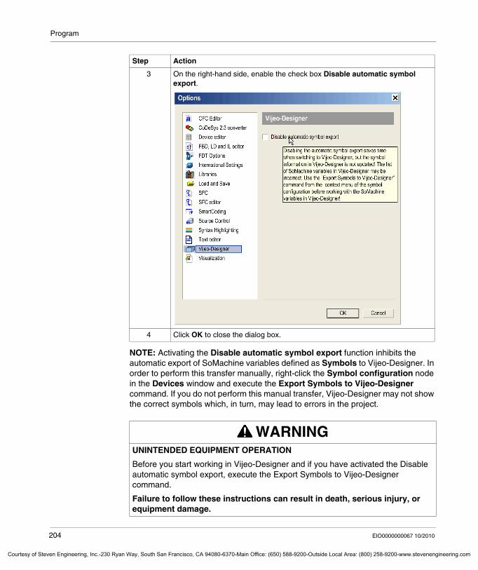
Program
Courtesy of St
NOTE: Activating the Disable automatic symbol export function inhibits the automatic export of SoMachine variables defined as Symbols to Vijeo-Designer. In order to perform this transfer manually, right-click the Symbol configuration node in the Devices window and execute the Export Symbols to Vijeo-Designer command. If you do not perform this manual transfer, Vijeo-Designer may not show the correct symbols which, in turn, may lead to errors in the project.
3 On the right-hand side, enable the check box Disable automatic symbol export.
4 Click OK to close the dialog box.
WARNINGUNINTENDED EQUIPMENT OPERATION
Before you start working in Vijeo-Designer and if you have activated the Disable automatic symbol export, execute the Export Symbols to Vijeo-Designer command.
Failure to follow these instructions can result in death, serious injury, or equipment damage.
Step Action
204 EIO0000000067 10/2010
even Engineering, Inc.-230 Ryan Way, South San Francisco, CA 94080-6370-Main Office: (650) 588-9200-Outside Local Area: (800) 258-9200-www.stevenengineering.com
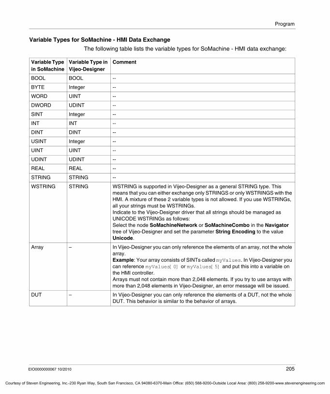
Program
Courtesy o
Variable Types for SoMachine - HMI Data Exchange
The following table lists the variable types for SoMachine - HMI data exchange:
Variable Type in SoMachine
Variable Type in Vijeo-Designer
Comment
BOOL BOOL --
BYTE Integer --
WORD UINT --
DWORD UDINT --
SINT Integer --
INT INT --
DINT DINT --
USINT Integer --
UINT UINT --
UDINT UDINT --
REAL REAL --
STRING STRING --
WSTRING STRING WSTRING is supported in Vijeo-Designer as a general STRING type. This means that you can either exchange only STRINGS or only WSTRINGS with the HMI. A mixture of these 2 variable types is not allowed. If you use WSTRINGs, all your strings must be WSTRINGs.Indicate to the Vijeo-Designer driver that all strings should be managed as UNICODE WSTRINGs as follows: Select the node SoMachineNetwork or SoMachineCombo in the Navigator tree of Vijeo-Designer and set the parameter String Encoding to the value Unicode.
Array – In Vijeo-Designer you can only reference the elements of an array, not the whole array.Example: Your array consists of SINTs called myValues. In Vijeo-Designer you can reference myValues[0] or myValues[5] and put this into a variable on the HMI controller.Arrays must not contain more than 2,048 elements. If you try to use arrays with more than 2,048 elements in Vijeo-Designer, an error message will be issued.
DUT – In Vijeo-Designer you can only reference the elements of a DUT, not the whole DUT. This behavior is similar to the behavior of arrays.
EIO0000000067 10/2010 205
f Steven Engineering, Inc.-230 Ryan Way, South San Francisco, CA 94080-6370-Main Office: (650) 588-9200-Outside Local Area: (800) 258-9200-www.stevenengineering.com
Program
Courtesy of St
Unsupported Variable Types
The following variable types are not supported for SoMachine - HMI data exchange:all 64-bit integer formatsLREALall time and date formatsnon-zero based arrays: You cannot import an array that is defined like myArray[1..100].
For further information on variable types for SoMachine - HMI data exchange see the Vijeo-Designer online help.
Identifier Length
In Vijeo-Designer the maximum length of the variable name is limited to 32 characters.
206 EIO0000000067 10/2010
even Engineering, Inc.-230 Ryan Way, South San Francisco, CA 94080-6370-Main Office: (650) 588-9200-Outside Local Area: (800) 258-9200-www.stevenengineering.com
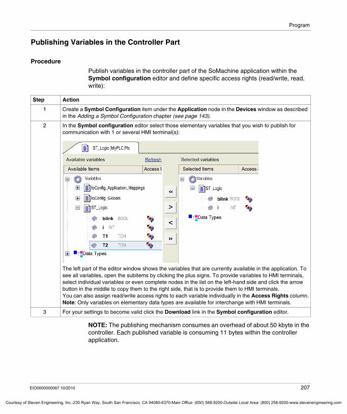
Program
Courtesy o
Publishing Variables in the Controller Part
Procedure
Publish variables in the controller part of the SoMachine application within the Symbol configuration editor and define specific access rights (read/write, read, write):
NOTE: The publishing mechanism consumes an overhead of about 50 kbyte in the controller. Each published variable is consuming 11 bytes within the controller application.
Step Action
1 Create a Symbol Configuration item under the Application node in the Devices window as described in the Adding a Symbol Configuration chapter (see page 143).
2 In the Symbol configuration editor select those elementary variables that you wish to publish for communication with 1 or several HMI terminal(s):
The left part of the editor window shows the variables that are currently available in the application. To see all variables, open the subitems by clicking the plus signs. To provide variables to HMI terminals, select individual variables or even complete nodes in the list on the left-hand side and click the arrow button in the middle to copy them to the right side, that is to provide them to HMI terminals.You can also assign read/write access rights to each variable individually in the Access Rights column.Note: Only variables on elementary data types are available for interchange with HMI terminals.
3 For your settings to become valid click the Download link in the Symbol configuration editor.
EIO0000000067 10/2010 207
f Steven Engineering, Inc.-230 Ryan Way, South San Francisco, CA 94080-6370-Main Office: (650) 588-9200-Outside Local Area: (800) 258-9200-www.stevenengineering.com
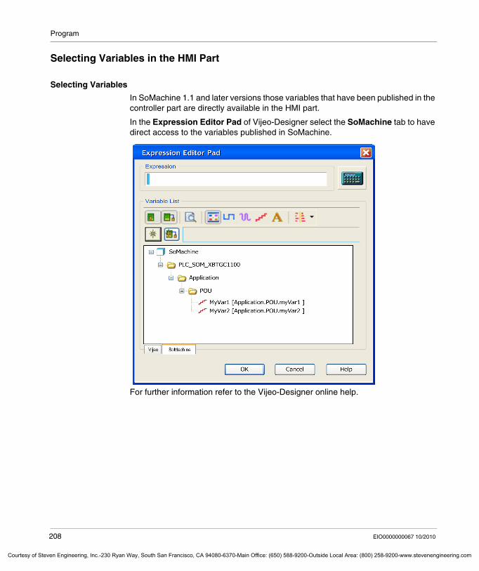
Program
Courtesy of St
Selecting Variables in the HMI Part
Selecting Variables
In SoMachine 1.1 and later versions those variables that have been published in the controller part are directly available in the HMI part.
In the Expression Editor Pad of Vijeo-Designer select the SoMachine tab to have direct access to the variables published in SoMachine.
For further information refer to the Vijeo-Designer online help.
208 EIO0000000067 10/2010
even Engineering, Inc.-230 Ryan Way, South San Francisco, CA 94080-6370-Main Office: (650) 588-9200-Outside Local Area: (800) 258-9200-www.stevenengineering.com
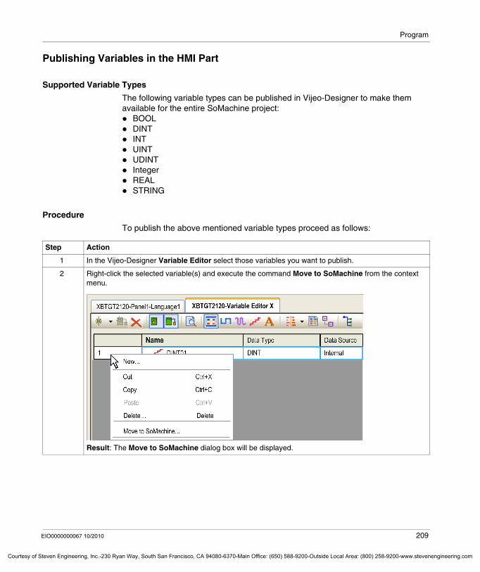
Program
Courtesy o
Publishing Variables in the HMI Part
Supported Variable Types
The following variable types can be published in Vijeo-Designer to make them available for the entire SoMachine project:
BOOLDINTINTUINTUDINTIntegerREALSTRING
Procedure
To publish the above mentioned variable types proceed as follows:
Step Action
1 In the Vijeo-Designer Variable Editor select those variables you want to publish.
2 Right-click the selected variable(s) and execute the command Move to SoMachine from the context menu.
Result: The Move to SoMachine dialog box will be displayed.
EIO0000000067 10/2010 209
f Steven Engineering, Inc.-230 Ryan Way, South San Francisco, CA 94080-6370-Main Office: (650) 588-9200-Outside Local Area: (800) 258-9200-www.stevenengineering.com
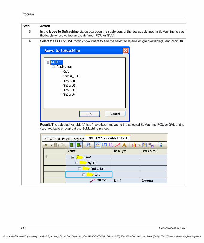
Program
Courtesy of St
3 In the Move to SoMachine dialog box open the subfolders of the devices defined in SoMachine to see the levels where variables are defined (POU or GVL).
4 Select the POU or GVL to which you want to add the selected Vijeo-Designer variable(s) and click OK.
Result: The selected variable(s) has / have been moved to the selected SoMachine POU or GVL and is / are available throughout the SoMachine project.
Step Action
210 EIO0000000067 10/2010
even Engineering, Inc.-230 Ryan Way, South San Francisco, CA 94080-6370-Main Office: (650) 588-9200-Outside Local Area: (800) 258-9200-www.stevenengineering.com
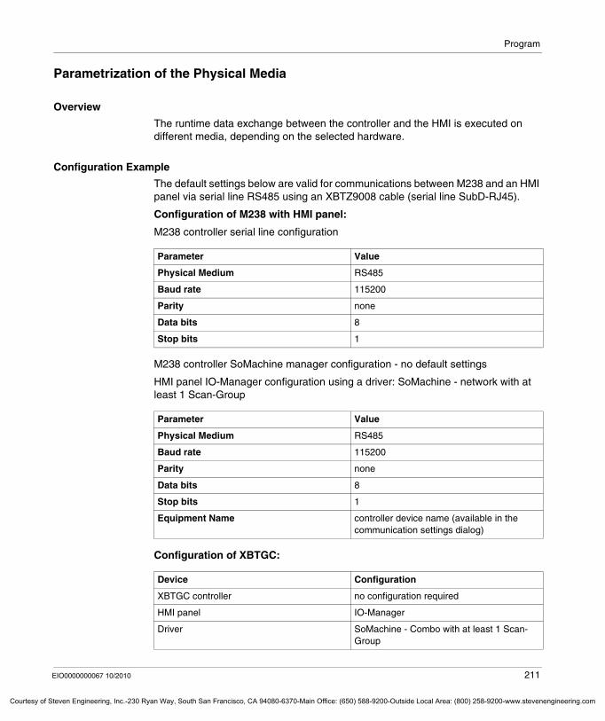
Program
Courtesy o
Parametrization of the Physical Media
Overview
The runtime data exchange between the controller and the HMI is executed on different media, depending on the selected hardware.
Configuration Example
The default settings below are valid for communications between M238 and an HMI panel via serial line RS485 using an XBTZ9008 cable (serial line SubD-RJ45).
Configuration of M238 with HMI panel:
M238 controller serial line configuration
M238 controller SoMachine manager configuration - no default settings
HMI panel IO-Manager configuration using a driver: SoMachine - network with at least 1 Scan-Group
Configuration of XBTGC:
Parameter Value
Physical Medium RS485
Baud rate 115200
Parity none
Data bits 8
Stop bits 1
Parameter Value
Physical Medium RS485
Baud rate 115200
Parity none
Data bits 8
Stop bits 1
Equipment Name controller device name (available in the communication settings dialog)
Device Configuration
XBTGC controller no configuration required
HMI panel IO-Manager
Driver SoMachine - Combo with at least 1 Scan-Group
EIO0000000067 10/2010 211
f Steven Engineering, Inc.-230 Ryan Way, South San Francisco, CA 94080-6370-Main Office: (650) 588-9200-Outside Local Area: (800) 258-9200-www.stevenengineering.com
Program
Courtesy of St
7.8 SoMachine Templates
What's in this Section?
This section contains the following topics:
Topic Page
General Information about SoMachine Templates 213
Supported Fieldbusses 215
Selecting SoMachine Templates for Your Project 217
Administration of SoMachine Templates 219
212 EIO0000000067 10/2010
even Engineering, Inc.-230 Ryan Way, South San Francisco, CA 94080-6370-Main Office: (650) 588-9200-Outside Local Area: (800) 258-9200-www.stevenengineering.com
Program
Courtesy o
General Information about SoMachine Templates
Overview
SoMachine provides templates in order to make dedicated control and visualization functionality, that has been developed in one SoMachine project, easily available to other SoMachine projects. They help to standardize the usage of I/O devices and applications throughout different SoMachine projects.
The following types of templates are available:device templates that are associated with a single I/O device function templates that are associated with a high-level application function
SoMachine provides various templates, but you can also create your own templates for any functionality you want to make available to other projects.
Using Already Installed SoMachine Templates
To use those templates that are provided by SoMachine, you merely have to make them available for your project as described in the chapter Selecting SoMachine Templates for Your Project (see page 217).
Creating Your Own Templates
The following steps are required for all SoMachine templates:
General Notes
When using SoMachine templates, note the following:Templates are not controller-specific and can therefore be made available for any controller. Make sure that the controller, to which you add the template, is capable of executing the functionality contained in the template.After the template has been installed, you can freely adapt the created objects to your individual requirements.The templates function does not support Vijeo-Designer applications. This means that HMI applications are not included in the SoMachine templates.
Step Action
1 Create your functionality within a SoMachine project and test it with the appropriate hardware or in the simulation.
2 Save the functionality in a template library.
3 Open another SoMachine project and instantiate the template from the template library in order to make the functionality available to this project.
EIO0000000067 10/2010 213
f Steven Engineering, Inc.-230 Ryan Way, South San Francisco, CA 94080-6370-Main Office: (650) 588-9200-Outside Local Area: (800) 258-9200-www.stevenengineering.com
Program
Courtesy of St
It is possible to install one template several times on the same controller device. In order to avoid naming conflicts when creating the same objects several times, they are renamed automatically during installation. For further information refer to the Naming of Objects section of the Adding Devices from Template chapter (see page 227).User-defined data types (DUT) or function blocks must be defined in a function block library if they should be used in templates.Templates do not support the use of direct representations of variables (for example %IX2.0) in templates. But you can, on the other hand, use direct representations with an incomplete address specification (for example %I*) in a template. For further information refer to the Variables configuration - VAR_CONFIG section of the CoDeSys online help.
214 EIO0000000067 10/2010
even Engineering, Inc.-230 Ryan Way, South San Francisco, CA 94080-6370-Main Office: (650) 588-9200-Outside Local Area: (800) 258-9200-www.stevenengineering.com
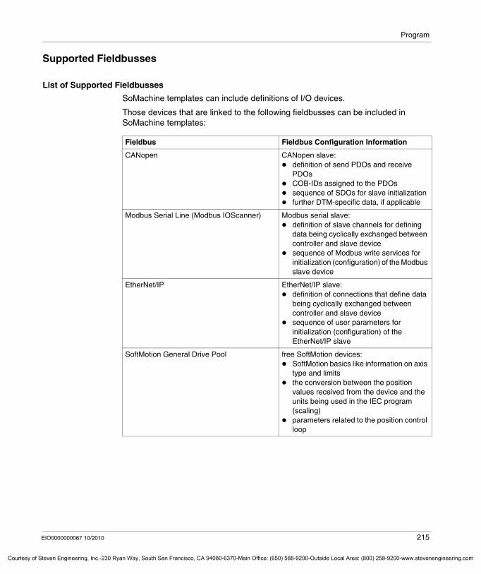
Program
Courtesy o
Supported Fieldbusses
List of Supported Fieldbusses
SoMachine templates can include definitions of I/O devices.
Those devices that are linked to the following fieldbusses can be included in SoMachine templates:
Fieldbus Fieldbus Configuration Information
CANopen CANopen slave:definition of send PDOs and receive PDOsCOB-IDs assigned to the PDOssequence of SDOs for slave initializationfurther DTM-specific data, if applicable
Modbus Serial Line (Modbus IOScanner) Modbus serial slave:definition of slave channels for defining data being cyclically exchanged between controller and slave devicesequence of Modbus write services for initialization (configuration) of the Modbus slave device
EtherNet/IP EtherNet/IP slave:definition of connections that define data being cyclically exchanged between controller and slave devicesequence of user parameters for initialization (configuration) of the EtherNet/IP slave
SoftMotion General Drive Pool free SoftMotion devices:SoftMotion basics like information on axis type and limitsthe conversion between the position values received from the device and the units being used in the IEC program (scaling)parameters related to the position control loop
EIO0000000067 10/2010 215
f Steven Engineering, Inc.-230 Ryan Way, South San Francisco, CA 94080-6370-Main Office: (650) 588-9200-Outside Local Area: (800) 258-9200-www.stevenengineering.com
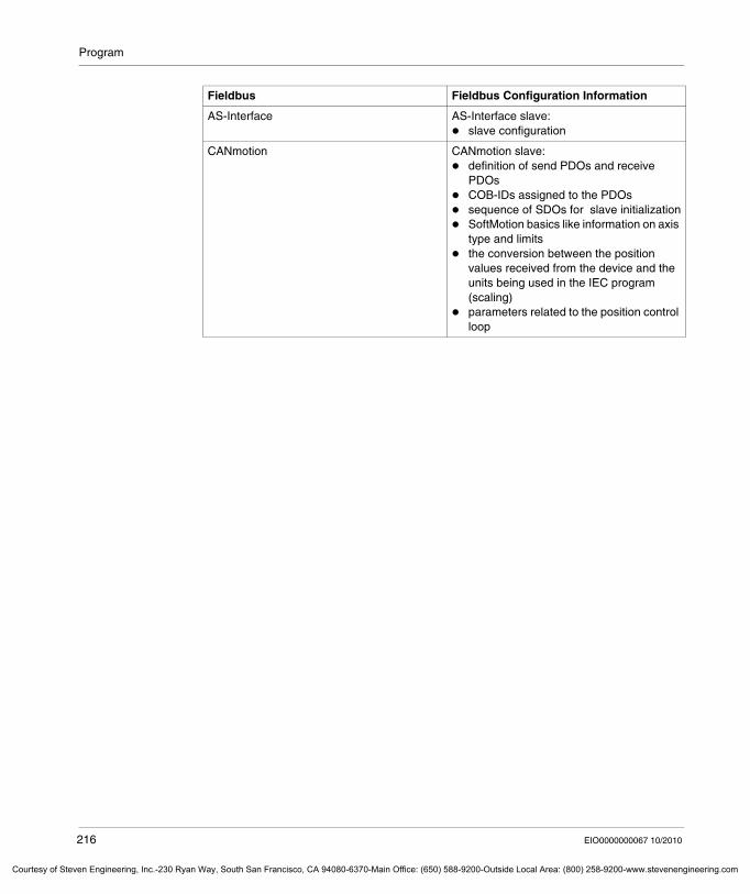
Program
Courtesy of St
AS-Interface AS-Interface slave:slave configuration
CANmotion CANmotion slave:definition of send PDOs and receive PDOsCOB-IDs assigned to the PDOssequence of SDOs for slave initializationSoftMotion basics like information on axis type and limitsthe conversion between the position values received from the device and the units being used in the IEC program (scaling)parameters related to the position control loop
Fieldbus Fieldbus Configuration Information
216 EIO0000000067 10/2010
even Engineering, Inc.-230 Ryan Way, South San Francisco, CA 94080-6370-Main Office: (650) 588-9200-Outside Local Area: (800) 258-9200-www.stevenengineering.com
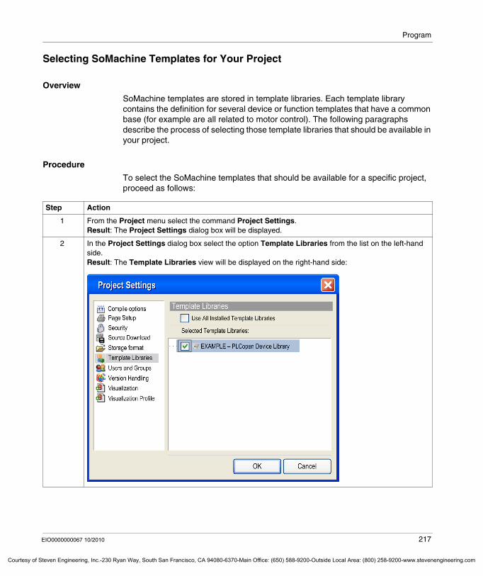
Program
Courtesy o
Selecting SoMachine Templates for Your Project
Overview
SoMachine templates are stored in template libraries. Each template library contains the definition for several device or function templates that have a common base (for example are all related to motor control). The following paragraphs describe the process of selecting those template libraries that should be available in your project.
Procedure
To select the SoMachine templates that should be available for a specific project, proceed as follows:
Step Action
1 From the Project menu select the command Project Settings.Result: The Project Settings dialog box will be displayed.
2 In the Project Settings dialog box select the option Template Libraries from the list on the left-hand side. Result: The Template Libraries view will be displayed on the right-hand side:
EIO0000000067 10/2010 217
f Steven Engineering, Inc.-230 Ryan Way, South San Francisco, CA 94080-6370-Main Office: (650) 588-9200-Outside Local Area: (800) 258-9200-www.stevenengineering.com
Program
Courtesy of St
3 The Template Libraries view provides the following options: You can either activate all available template libraries for your project by activating the checkbox Use All Installed Template Libraries. This is the default setting for any new projects.Or you can select specific template libraries, that is the device or function templates they include, from the Selected Template Libraries list.
NOTE: With the latter option it is neither possible to save new device or function templates into those template libraries that are not selected nor to use device templates or function templates from not selected template libraries for creating new field devices.
4 Click OK to activate the selected template libraries for your project.
Step Action
218 EIO0000000067 10/2010
even Engineering, Inc.-230 Ryan Way, South San Francisco, CA 94080-6370-Main Office: (650) 588-9200-Outside Local Area: (800) 258-9200-www.stevenengineering.com
Program
Courtesy o
Administration of SoMachine Templates
Overview
The following paragraphs provide an overview of how to create new or change existing device or function templates and to save them as file for transferring them to other PCs.
Template Libraries
Template libraries contain the definition of several device or function templates.
Write Protection
The following template libraries are write-protected, which means that they cannot be deleted or renamed:
the standard template libraries that are included in the SoMachine scope of deliverytemplate libraries that are installed in the Template Repository
NOTE: You cannot change write-protected libraries (uninstalling individual templates or changing names), but you can completely uninstall them.
EIO0000000067 10/2010 219
f Steven Engineering, Inc.-230 Ryan Way, South San Francisco, CA 94080-6370-Main Office: (650) 588-9200-Outside Local Area: (800) 258-9200-www.stevenengineering.com
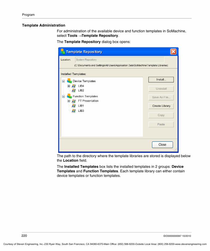
Program
Courtesy of St
Template Administration
For administration of the available device and function templates in SoMachine, select Tools → Template Repository.
The Template Repository dialog box opens:
The path to the directory where the template libraries are stored is displayed below the Location field.
The Installed Templates box lists the installed templates in 2 groups: Device Templates and Function Templates. Each template library can either contain device templates or function templates.
220 EIO0000000067 10/2010
even Engineering, Inc.-230 Ryan Way, South San Francisco, CA 94080-6370-Main Office: (650) 588-9200-Outside Local Area: (800) 258-9200-www.stevenengineering.com
Program
Courtesy o
Installing Additional Template Libraries
To add additional template libraries to this list, proceed as follows:
Removing Template Libraries (Device or Function Templates)
To remove a template library (device or a function template), proceed as follows:
Renaming Template Libraries (Device or Function Templates)
To rename a template library (device or function template), proceed as follows:
Step Action
1 Click the Install button in the Template Repository dialog box.Result: A File open dialog box opens.
2 Browse to the folder where the template library file you want to install is saved.
3 Select the library file you want to install and click OK.Result: The selected template library will be installed and will be indicated in the Template Repository dialog box, including the device or function templates it contains.
Step Action
1 In the Installed Templates list of the Template Repository dialog box, select the template library (device or function template) you want to remove.
2 To remove the selected template library (device or function template), click the Uninstall button.Result: The selected template library (device or function template) will be removed from the installation.
Step Action
1 In the Installed Templates list of the Template Repository dialog box, select the template library (device or function template) you want to rename.
2 Click on the name you want to change.Result: A text box opens.
3 Enter the new name in the text box and press Enter or leave the text box.Result: The template library (device or function template) is now assigned the new name.
EIO0000000067 10/2010 221
f Steven Engineering, Inc.-230 Ryan Way, South San Francisco, CA 94080-6370-Main Office: (650) 588-9200-Outside Local Area: (800) 258-9200-www.stevenengineering.com
Program
Courtesy of St
Creating a new Template Library
To create a new template library, proceed as follows:
Saving Template Libraries as File
The template libraries that contain device or function templates are SoMachine-specific XML files.
To provide them for use on other PCs, proceed as follows:
Copy and Paste Operations for Template Libraries
The Template Repository dialog box also supports the copy and paste operation for template libraries.
To copy a template library with the device or function template it contains, select the respective item in the Installed Templates list and click the Copy button.
Now click the Paste button to insert a copy of this template library with a default name in the Installed Templates list.
Step Action
1 To create a new template library for device templates, select the Device Templates node in the Installed Templates list and click the Create Library button of the Template Repository dialog box.Result: A new template library with a default name is added at the bottom of the Device Templates section of the Installed Templates list.To create a new template library for function templates, select the Function Templates node in the Installed Templates list and click the Create Library button of the Template Repository dialog box.Result: A new template library with a default name is added at the bottom of the Function Templates section of the Installed Templates list.
2 Rename the new template library as stated above and fill it with device or function templates by using for example the copy and paste operations described below.
Step Action
1 Select the template library you want to export in the Installed Templates list.
2 Click the Save As File... button.
3 In the Save File dialog box navigate to the folder where you want to save the template library file.
4 Transfer the template library file to the other PC and install it by using the Template Repository.
222 EIO0000000067 10/2010
even Engineering, Inc.-230 Ryan Way, South San Francisco, CA 94080-6370-Main Office: (650) 588-9200-Outside Local Area: (800) 258-9200-www.stevenengineering.com
Program
Courtesy o
This new template library will automatically be inserted below the correct node. This means that template libraries that include device templates will automatically be inserted below the Device Templates node while template libraries including function templates will automatically be inserted below the Function Templates node.
Replace the default name by a name of your choice.
Copy and Paste Operations for Templates
The Template Repository dialog box supports the copy and paste operation for device or function templates.
To copy a device or function template, select the respective item from below a template library’s node in the Installed Templates list and click the Copy button.
You can now paste a device template underneath a template library below the Device Templates node.
A library can only be pasted into a library of the same kind.
Replace the default name by a name of your choice.
EIO0000000067 10/2010 223
f Steven Engineering, Inc.-230 Ryan Way, South San Francisco, CA 94080-6370-Main Office: (650) 588-9200-Outside Local Area: (800) 258-9200-www.stevenengineering.com
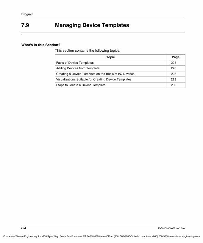
Program
Courtesy of St
7.9 Managing Device Templates
What's in this Section?
This section contains the following topics:
Topic Page
Facts of Device Templates 225
Adding Devices from Template 226
Creating a Device Template on the Basis of I/O Devices 228
Visualizations Suitable for Creating Device Templates 229
Steps to Create a Device Template 230
224 EIO0000000067 10/2010
even Engineering, Inc.-230 Ryan Way, South San Francisco, CA 94080-6370-Main Office: (650) 588-9200-Outside Local Area: (800) 258-9200-www.stevenengineering.com
Program
Courtesy o
Facts of Device Templates
Content of Device Templates
Device templates are related to a specific field device. They contain the following information:
fieldbus configurationdevice logic (controller programming) (optional)visualization elements (visualization programming) (optional)
Using Device Templates
Already available device templates are saved in template libraries. Each template library contains the definition for several device templates that have a common base (are related to motor control, for example).
You can easily select them and adapt them to the requirements of your individual SoMachine projects in order to create new preconfigured and ready to use field devices.
Creating New Device Templates
To make your already configured field devices reusable for any SoMachine project, you can save them as device templates. This also includes the controller programming and visualization linked to this field device.
EIO0000000067 10/2010 225
f Steven Engineering, Inc.-230 Ryan Way, South San Francisco, CA 94080-6370-Main Office: (650) 588-9200-Outside Local Area: (800) 258-9200-www.stevenengineering.com
Program
Courtesy of St
Adding Devices from Template
Overview
Device templates are always related to a specific fieldbus device. They contain the following information:
fieldbus device configurationdevice logic (controller programming) (optional)visualization elements (visualization programming) (optional)
The device templates you want to use must be available and enabled in the Template Repository of SoMachine. For details refer to the Administration of SoMachine Templates chapter (see page 219).
You can create your own device templates from your project. For details refer to the Steps to Create a Device Template chapter (see page 230).
Add Device from Template
Create a device using a device template as follows:
NOTE: The undo / redo function is not available for the process of creating I/O devices.
Step Action
1 In the Devices window right-click the I/O device manager and select Add Device from Template from the context menu.Result: The Add Device From Template dialog box will be displayed.
2 In the Add Device From Template dialog box select the Device Template to be used, and set the Device Name as well as the Device Address if the fieldbus requires numerical addresses.In case the device templates includes logic, select the program (POU) in which the logic will be inserted.
3 Click on the OK button.Result: The device will be created and parametrized according to the selected device template including the optional visualization screen(s) and logic.
226 EIO0000000067 10/2010
even Engineering, Inc.-230 Ryan Way, South San Francisco, CA 94080-6370-Main Office: (650) 588-9200-Outside Local Area: (800) 258-9200-www.stevenengineering.com
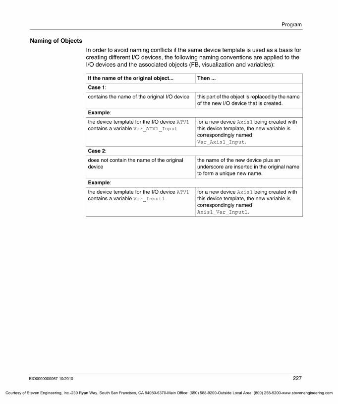
Program
Courtesy o
Naming of Objects
In order to avoid naming conflicts if the same device template is used as a basis for creating different I/O devices, the following naming conventions are applied to the I/O devices and the associated objects (FB, visualization and variables):
If the name of the original object... Then ...
Case 1:
contains the name of the original I/O device this part of the object is replaced by the name of the new I/O device that is created.
Example:
the device template for the I/O device ATV1 contains a variable Var_ATV1_Input
for a new device Axis1 being created with this device template, the new variable is correspondingly named Var_Axis1_Input.
Case 2:
does not contain the name of the original device
the name of the new device plus an underscore are inserted in the original name to form a unique new name.
Example:
the device template for the I/O device ATV1 contains a variable Var_Input1
for a new device Axis1 being created with this device template, the new variable is correspondingly named Axis1_Var_Input1.
EIO0000000067 10/2010 227
f Steven Engineering, Inc.-230 Ryan Way, South San Francisco, CA 94080-6370-Main Office: (650) 588-9200-Outside Local Area: (800) 258-9200-www.stevenengineering.com
Program
Courtesy of St
Creating a Device Template on the Basis of I/O Devices
Overview
The following paragraphs listthe criteria that must be fulfilled in order to save an I/O device, including logic and visualization, as device templatethe information that is saved in the device template
Prerequisites for Devices
The I/O devices including logic and visualization must meet the following criteria in order to be saved as device templates:
I/O devices including logic and visualization must be linked to the fieldbusses listed in the Supported Fieldbusses chapter (see page 215).The device type must be installed in the Device Repository.
Prerequisites for the Application
You can only create templates from correct applications, which means that no errors are detected during the build process.
Prerequisites for Including a Function Block into a Template
In order to insert a function block into a template, it is required that the program including this function block is in fact executed (added to a task or called by another program). Otherwise it will not be considered when executing the Build command.
Device Information Saved in Device Templates
The following information of I/O devices is saved in device templates:fieldbus configurationI/O mapping of the I/O devicefunction blocks that are suitable for the I/O devicevisualizations that are suitable for the I/O device
228 EIO0000000067 10/2010
even Engineering, Inc.-230 Ryan Way, South San Francisco, CA 94080-6370-Main Office: (650) 588-9200-Outside Local Area: (800) 258-9200-www.stevenengineering.com
Program
Courtesy o
Visualizations Suitable for Creating Device Templates
Overview
Each device template can be associated with 1 or more CoDeSys visualizations. The supported kinds of visualizations are described in the following.
Supported Visualizations
SoMachine supports the following kinds of visualizations:visualizations with frame (recommended)visualizations without frame
Visualizations with Frame
Visualizations with frame are based on a "visualization type". Visualization types are visualizations embedded into another visualization. They must be embedded in a library and you must define for each visualization type an interface that includes definitions of all variables related to the connection to the I/O device or function block.
SoMachine creates a visualization with an included frame object for the I/O device with the frame object referencing the visualization type.
When you create a new device based on this device template, SoMachine adapts the placeholders of the visualization type to the created I/O device.
NOTE: It is required that the visualizations with frame linked to the I/O device are defined in a library to help to ensure that SoMachine automatically detects them.
Visualizations without Frame
Visualizations without frame are based on a visualization object, created for the I/O device.
SoMachine references the data of the I/O device within the properties of the visual elements.
When you create a new device based on this device template, SoMachine directly replaces the variables in the properties of the visual elements.
EIO0000000067 10/2010 229
f Steven Engineering, Inc.-230 Ryan Way, South San Francisco, CA 94080-6370-Main Office: (650) 588-9200-Outside Local Area: (800) 258-9200-www.stevenengineering.com
Program
Courtesy of St
Steps to Create a Device Template
Overview
The following paragraphs list the steps that have to be performed in order to save I/O devices meeting the criteria stated in Creating a Device Template on the Basis of I/O Devices (see page 228).
Steps for Saving an I/O Device as Template
To save an already existing I/O device as device template, proceed as follows:
Step Action
1 Right-click the I/O device you want to save as device template in the Devices view of SoMachine.
2 Select the command Save As Template from the context menu.Result: SoMachine automatically builds the application. After the built process has been successfully completed, the Save as Template dialog box will be displayed.
3 Define the new device template in the Save as Template dialog box as stated below.
4 Click OK to close the Save as Template dialog box and to create your new device template.
230 EIO0000000067 10/2010
even Engineering, Inc.-230 Ryan Way, South San Francisco, CA 94080-6370-Main Office: (650) 588-9200-Outside Local Area: (800) 258-9200-www.stevenengineering.com
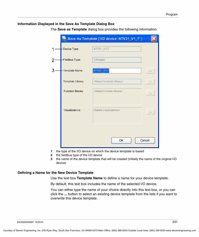
Program
Courtesy o
Information Displayed in the Save As Template Dialog Box
The Save as Template dialog box provides the following information:
1 the type of the I/O device on which the device template is based 2 the fieldbus type of the I/O device3 the name of the device template that will be created (initially the name of the original I/O
device)
Defining a Name for the New Device Template
Use the text box Template Name to define a name for your device template.
By default, this text box includes the name of the selected I/O device.
You can either type the name of your choice directly into this text box, or you can click the ... button to select an existing device template from the lists if you want to overwrite this device template.
EIO0000000067 10/2010 231
f Steven Engineering, Inc.-230 Ryan Way, South San Francisco, CA 94080-6370-Main Office: (650) 588-9200-Outside Local Area: (800) 258-9200-www.stevenengineering.com
Program
Courtesy of St
Selecting the Template Library
To select one of the previously installed or created template libraries in which the device template should be stored, proceed as follows:
Selecting the Function Blocks
To select the function block instances that are handling the I/O device, proceed as follows:
The function block is linked to the I/O device if a function block parameteris connected with a variable that is used in the I/O mapping of the I/O device.is connected with a predefined global variable (for example Axis_Ref) of the I/O device.
The following parameters will be saved in the template:constantsall variables that are linked to the I/O devicethose variables that are not linked to the I/O device but are defined in a POU
NOTE: Variables that are defined in the GVL are not saved in the template.
NOTE: Expressions are not saved in the template.
Step Action
1 In the Save as Template dialog box click the ... button right to the Template Library text box.Result: The Select Template Library dialog box will be displayed.
2 The Select Template Library dialog box displays all template libraries that have been installed for the current project or have been created. Write-protected template libraries are not displayed.To add the new device template to 1 of these template libraries, select the suitable entry and click OK.
Step Action
1 In the Save as Template dialog box click the ... button right to the Function Blocks text box.Result: The Select Function Block dialog box will be displayed.
2 The Select Function Block dialog box displays those function block instances of the I/O device that meet the following requirements for template creation:
The function block must be linked to the I/O device. The function block must be located in a program that is in fact executed (added to a task or called by another program).
NOTE: It is recommended that the function block is only called once. Otherwise problems may occur detecting the correct call to be included in the template. Furthermore the function block type must be defined in a library.
232 EIO0000000067 10/2010
even Engineering, Inc.-230 Ryan Way, South San Francisco, CA 94080-6370-Main Office: (650) 588-9200-Outside Local Area: (800) 258-9200-www.stevenengineering.com
Program
Courtesy o
Selecting the Visualizations
To select the visualizations that are handling the I/O device, proceed as follows:
A visualization is linked to a function block if a property of the visualization usesa variable that is connected to a parameter of the function block.the function block variable itself.
Step Action
1 In the Save as Template dialog box click the ... button right to the Visualizations text box.Result: The Select Visualizations dialog box will be displayed.
2 The Select Visualizations dialog box displays those visualizations that are linked with the I/O device or with one of the selected function blocks.The visualization is linked to the I/O device if 1 property of the visualization uses a variable that is used in the I/O mapping of the I/O device.
EIO0000000067 10/2010 233
f Steven Engineering, Inc.-230 Ryan Way, South San Francisco, CA 94080-6370-Main Office: (650) 588-9200-Outside Local Area: (800) 258-9200-www.stevenengineering.com
Program
Courtesy of St
7.10 Managing Function Templates
What's in this Section?
This section contains the following topics:
Topic Page
Facts of Function Templates 235
Adding Functions From Template 236
Application Functions as Basis for Function Templates 239
Steps to Create a Function Template 241
234 EIO0000000067 10/2010
even Engineering, Inc.-230 Ryan Way, South San Francisco, CA 94080-6370-Main Office: (650) 588-9200-Outside Local Area: (800) 258-9200-www.stevenengineering.com
Program
Courtesy o
Facts of Function Templates
Content of Function Templates
Function templates represent dedicated control and visualization functionality that are associated with an application function.
A function template may include the following elements: IEC program(s)I/O device(s) that is / are being used by the application functionCoDeSys visualization(s) that is / are being used to visualize the application functionglobal variable list(s) global variable(s) that may be shared with other application functionstracesCAM tables
NOTE: Please note that any HMI elements related to CoDeSys are not supported by this function.
Using Function Templates
Already available function templates are saved in template libraries. Each template library contains the definition for several function templates that have a common base (for example, all are related to packaging applications).
You can easily select them and adapt them to the requirements of your individual SoMachine projects in order to create new ready to use application functions.
Creating New Function Templates
To make your already created application function reusable for any SoMachine project, you can save it as function template.
When you save the function template you must decide in which template library it should be stored.
EIO0000000067 10/2010 235
f Steven Engineering, Inc.-230 Ryan Way, South San Francisco, CA 94080-6370-Main Office: (650) 588-9200-Outside Local Area: (800) 258-9200-www.stevenengineering.com
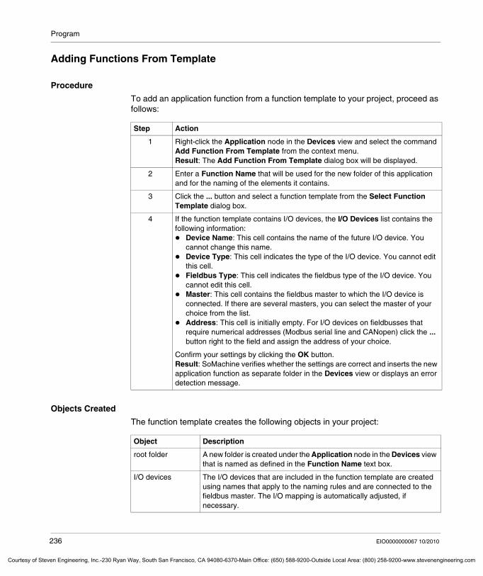
Program
Courtesy of St
Adding Functions From Template
Procedure
To add an application function from a function template to your project, proceed as follows:
Objects Created
The function template creates the following objects in your project:
Step Action
1 Right-click the Application node in the Devices view and select the command Add Function From Template from the context menu.Result: The Add Function From Template dialog box will be displayed.
2 Enter a Function Name that will be used for the new folder of this application and for the naming of the elements it contains.
3 Click the ... button and select a function template from the Select Function Template dialog box.
4 If the function template contains I/O devices, the I/O Devices list contains the following information:
Device Name: This cell contains the name of the future I/O device. You cannot change this name. Device Type: This cell indicates the type of the I/O device. You cannot edit this cell.Fieldbus Type: This cell indicates the fieldbus type of the I/O device. You cannot edit this cell.Master: This cell contains the fieldbus master to which the I/O device is connected. If there are several masters, you can select the master of your choice from the list.Address: This cell is initially empty. For I/O devices on fieldbusses that require numerical addresses (Modbus serial line and CANopen) click the ... button right to the field and assign the address of your choice.
Confirm your settings by clicking the OK button.Result: SoMachine verifies whether the settings are correct and inserts the new application function as separate folder in the Devices view or displays an error detection message.
Object Description
root folder A new folder is created under the Application node in the Devices view that is named as defined in the Function Name text box.
I/O devices The I/O devices that are included in the function template are created using names that apply to the naming rules and are connected to the fieldbus master. The I/O mapping is automatically adjusted, if necessary.
236 EIO0000000067 10/2010
even Engineering, Inc.-230 Ryan Way, South San Francisco, CA 94080-6370-Main Office: (650) 588-9200-Outside Local Area: (800) 258-9200-www.stevenengineering.com
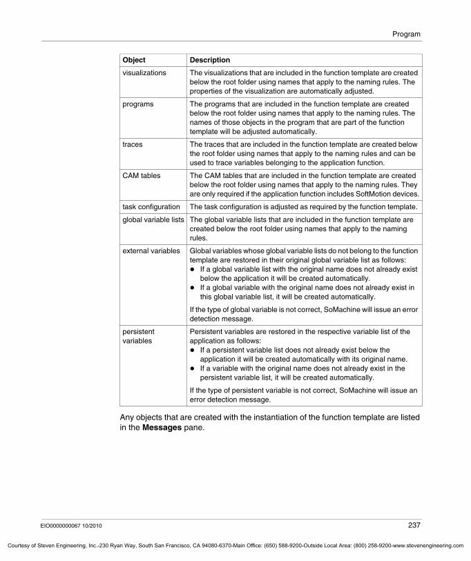
Program
Courtesy o
Any objects that are created with the instantiation of the function template are listed in the Messages pane.
visualizations The visualizations that are included in the function template are created below the root folder using names that apply to the naming rules. The properties of the visualization are automatically adjusted.
programs The programs that are included in the function template are created below the root folder using names that apply to the naming rules. The names of those objects in the program that are part of the function template will be adjusted automatically.
traces The traces that are included in the function template are created below the root folder using names that apply to the naming rules and can be used to trace variables belonging to the application function.
CAM tables The CAM tables that are included in the function template are created below the root folder using names that apply to the naming rules. They are only required if the application function includes SoftMotion devices.
task configuration The task configuration is adjusted as required by the function template.
global variable lists The global variable lists that are included in the function template are created below the root folder using names that apply to the naming rules.
external variables Global variables whose global variable lists do not belong to the function template are restored in their original global variable list as follows:
If a global variable list with the original name does not already exist below the application it will be created automatically.If a global variable with the original name does not already exist in this global variable list, it will be created automatically.
If the type of global variable is not correct, SoMachine will issue an error detection message.
persistent variables
Persistent variables are restored in the respective variable list of the application as follows:
If a persistent variable list does not already exist below the application it will be created automatically with its original name.If a variable with the original name does not already exist in the persistent variable list, it will be created automatically.
If the type of persistent variable is not correct, SoMachine will issue an error detection message.
Object Description
EIO0000000067 10/2010 237
f Steven Engineering, Inc.-230 Ryan Way, South San Francisco, CA 94080-6370-Main Office: (650) 588-9200-Outside Local Area: (800) 258-9200-www.stevenengineering.com
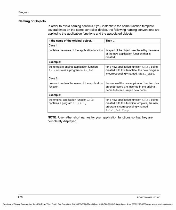
Program
Courtesy of St
Naming of Objects
In order to avoid naming conflicts if you instantiate the same function template several times on the same controller device, the following naming conventions are applied to the application functions and the associated objects:
NOTE: Use rather short names for your application functions so that they are completely displayed.
If the name of the original object... Then ...
Case 1:
contains the name of the application function this part of the object is replaced by the name of the new application function that is created.
Example:
the template original application function Axis contains a program Axis_Init
for a new application function Axis1 being created with this template, the new program is correspondingly named Axis1_Init.
Case 2:
does not contain the name of the application function
the name of the new application function plus an underscore are inserted in the original name to form a unique new name.
Example:
the original application function Axis contains a program InitProg
for a new application function Axis1 being created with this function template, the new program is correspondingly named Axis1_InitProg.
238 EIO0000000067 10/2010
even Engineering, Inc.-230 Ryan Way, South San Francisco, CA 94080-6370-Main Office: (650) 588-9200-Outside Local Area: (800) 258-9200-www.stevenengineering.com
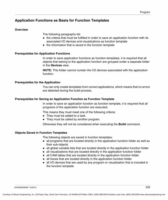
Program
Courtesy o
Application Functions as Basis for Function Templates
Overview
The following paragraphs listthe criteria that must be fulfilled in order to save an application function with its associated I/O devices and visualizations as function templatethe information that is saved in the function template
Prerequisites for Application Functions
In order to save application functions as function templates, it is required that all objects that belong to the application function are grouped under a separate folder in the Devices view.
NOTE: This folder cannot contain the I/O devices associated with the application function.
Prerequisites for the Application
You can only create templates from correct applications, which means that no errors are detected during the build process.
Prerequisites for Saving an Application Function as Function Template
In order to save an application function as function template, it is required that all programs of the application function are executed.
This means they must meet one of the following criteria:They must be added to a task.They must be called by another program.
Otherwise they will not be considered when executing the Build command.
Objects Saved in Function Templates
The following objects are saved in function templates:all programs that are located directly in the application function folder as well as their sub-objectsall global variable lists that are located directly in the application function folderall visualizations that are located directly in the application function folderall CAM tables that are located directly in the application function folderall traces that are located directly in the application function folderall I/O devices that are used by any program or visualization that is included in the function template
EIO0000000067 10/2010 239
f Steven Engineering, Inc.-230 Ryan Way, South San Francisco, CA 94080-6370-Main Office: (650) 588-9200-Outside Local Area: (800) 258-9200-www.stevenengineering.com

Program
Courtesy of St
all global variables whose variable lists are not part of the function template but which are used by any program or visualization that is part of the function templateall persistent variables that are used by any program or visualization that is part of the function template
NOTE: Any other object types are not saved in the function template (even if they are saved in the application function folder). Only use function blocks and data types that are stored in a library.
240 EIO0000000067 10/2010
even Engineering, Inc.-230 Ryan Way, South San Francisco, CA 94080-6370-Main Office: (650) 588-9200-Outside Local Area: (800) 258-9200-www.stevenengineering.com
Program
Courtesy o
Steps to Create a Function Template
Overview
The following paragraphs list the steps that have to be performed in order to save already available application functions that meet the criteria stated in Application Functions as Basis for Function Templates (see page 239) as function templates.
Procedure
To save an already available application function as function template, proceed as follows:
Assigning a Template Name
In the Template Name text box of the Save as Function Template dialog box you define the name under which the function template is stored in the template library. By default, this text box contains the name of the folder that contains your application function in the Devices view but you can adapt the name to your individual requirements.
Selecting a Template Library
So select one of the previously installed or created template libraries in which your new function template should be stored, proceed as follows:
Step Action
1 Right-click the folder that contains your application function in the Devices view.
2 Select the command Save As Function Template from the context menu.Result: The Save as Function Template dialog box will be displayed.
3 Assign a Template Name and a Template Library as stated below.
4 Click OK to close the Save as Function Template dialog box and to create your new function template.Result: SoMachine verifies that the function template can be created and displays a message that the function template has been created successfully or issues messages indicating the detected errors.
Step Action
1 In the Save as Function Template dialog box click on the ... button next to the Template Library text box.Result: The Select Template Library dialog box will be displayed.
2 The Select Template Library dialog box displays all template libraries that have been installed for the current project or have been created. Write-protected libraries are not displayed.To add your new function template to one of these template libraries, select the suitable entry and click OK.
EIO0000000067 10/2010 241
f Steven Engineering, Inc.-230 Ryan Way, South San Francisco, CA 94080-6370-Main Office: (650) 588-9200-Outside Local Area: (800) 258-9200-www.stevenengineering.com
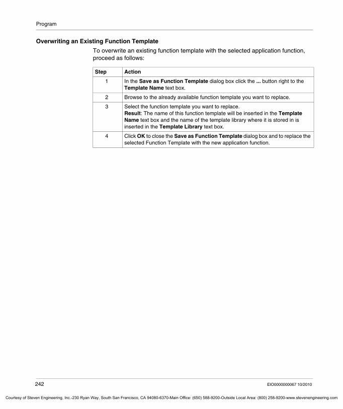
Program
Courtesy of St
Overwriting an Existing Function Template
To overwrite an existing function template with the selected application function, proceed as follows:
Step Action
1 In the Save as Function Template dialog box click the ... button right to the Template Name text box.
2 Browse to the already available function template you want to replace.
3 Select the function template you want to replace.Result: The name of this function template will be inserted in the Template Name text box and the name of the template library where it is stored in is inserted in the Template Library text box.
4 Click OK to close the Save as Function Template dialog box and to replace the selected Function Template with the new application function.
242 EIO0000000067 10/2010
even Engineering, Inc.-230 Ryan Way, South San Francisco, CA 94080-6370-Main Office: (650) 588-9200-Outside Local Area: (800) 258-9200-www.stevenengineering.com
Program
Courtesy o
7.11 Transferring and Running Applications
What's in this Section?
This section contains the following topics:
Topic Page
Transferring Applications 244
Running Applications 248
EIO0000000067 10/2010 243
f Steven Engineering, Inc.-230 Ryan Way, South San Francisco, CA 94080-6370-Main Office: (650) 588-9200-Outside Local Area: (800) 258-9200-www.stevenengineering.com
Program
Courtesy of St
Transferring Applications
Introduction
To run an application, you must first connect the PC to the controller, then transfer the application to the controller.
Transferring a project allows you to copy the current project from SoMachine to the controller memory.
NOTE: Due to memory size limitation, some controllers are not able to store the application source but only a built application that is executed. This means that you are not able to upload the application source from the controller to a PC.
Preconditions
Your application must fulfill the following conditions before transferring it to the controller:
the active path must be set for the controller,the application you want to transfer must be active,the application must be free from compilation errors.
Boot Application
The Boot Application is the application that will be launched on controller start. This application is stored in the controller memory. To configure the download of the boot application, right-click the Application node in the Devices view and select the Properties command. A
t the end of a successful transfer of a new application, a message is displayed asking you if you want to create the boot application.
WARNINGUNINTENDED EQUIPMENT OPERATION
Whenever you login to your controller, ensure the following:The software application being downloaded must be installed on the intended device. Confirm you have entered the correct device designation or device address.Guards must be in place so that unintended equipment operation will not cause injury to personnel or damage to equipment.You must have read and understood the user documentation of the software and devices involved and must know how to operate the equipment.
Failure to follow these instructions can result in death, serious injury, or equipment damage.
244 EIO0000000067 10/2010
even Engineering, Inc.-230 Ryan Way, South San Francisco, CA 94080-6370-Main Office: (650) 588-9200-Outside Local Area: (800) 258-9200-www.stevenengineering.com
Program
Courtesy o
You can manually create a boot application in the following ways: In offline mode: Click Online → Create boot application to save the boot application to a file.In online mode, with the application being in STOP mode: Click Online → Create boot application to download the boot application to the controller.
Operating Modes
The transfer method differs depending on the relationship between the loaded application and the application you want to transfer. The 3 cases are:
Case 1: The application in the controller is the same as the one you want to load. In this case, no transfer occurs, you just connect SoMachine to the controllerCase 2: You made modifications of the application that is loaded in the controller. In this case you can specify if you want to transfer all or parts of the modified application or keep the application in the controller as it is.Case 3: The controller application is different to the one you want to load. In this case, you must specify if you want to connect the loaded application or if you want to load the new one.
Transferring your Application to the Controller: Case 1
Step Action
1 To connect to the controller, select Online → Login to ’Application[YourApplicationName; Plc Logic]’.
2 You are connected to the controller.
EIO0000000067 10/2010 245
f Steven Engineering, Inc.-230 Ryan Way, South San Francisco, CA 94080-6370-Main Office: (650) 588-9200-Outside Local Area: (800) 258-9200-www.stevenengineering.com
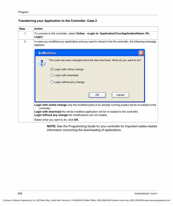
Program
Courtesy of St
Transferring your Application to the Controller: Case 2
NOTE: See the Programming Guide for your controller for important safety-related information concerning the downloading of applications.
Step Action
1 To connect to the controller, select Online → Login to ’Application[YourApplicationName; Plc Logic]’.
2 In case you modified your application and you want to reload it into the controller, the following message appears:
Login with online change only the modified parts of an already running project will be re-loaded to the controller.
Login with download the whole modified application will be re-loaded to the controller.Login without any change the modifications are not loaded.
Select what you want to do, click OK.
246 EIO0000000067 10/2010
even Engineering, Inc.-230 Ryan Way, South San Francisco, CA 94080-6370-Main Office: (650) 588-9200-Outside Local Area: (800) 258-9200-www.stevenengineering.com
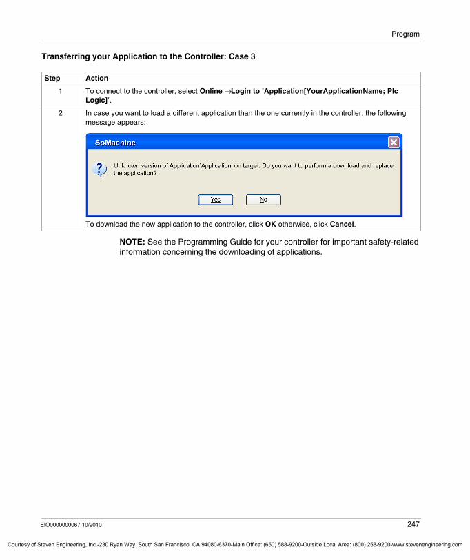
Program
Courtesy o
Transferring your Application to the Controller: Case 3
NOTE: See the Programming Guide for your controller for important safety-related information concerning the downloading of applications.
Step Action
1 To connect to the controller, select Online → Login to ’Application[YourApplicationName; Plc Logic]’.
2 In case you want to load a different application than the one currently in the controller, the following message appears:
To download the new application to the controller, click OK otherwise, click Cancel.
EIO0000000067 10/2010 247
f Steven Engineering, Inc.-230 Ryan Way, South San Francisco, CA 94080-6370-Main Office: (650) 588-9200-Outside Local Area: (800) 258-9200-www.stevenengineering.com
Program
Courtesy of St
Running Applications
Introduction
This part shows how to start/stop an application.
RUN/STOP with SoMachine
The controller can be started and stopped using SoMachine run on a PC connected to the controller.
Click Online → Start ‘Application [ApplicationName: Plc logic]’ or CTRL+F5 or the Start ’Application [ApplicationName: Plc logic]’ button in the menu bar to start the application.
Click Online → Stop ‘Application [ApplicationName: Plc logic]’ or CTRL+SHIFT+F5 or the Stop ’Application [ApplicationName: Plc logic]’ button in the menu bar to stop the application.
RUN/STOP Input for Controllers
Some controllers allow you to configure a Run/Stop input (for example %IX0.0...%IX1.5) to control application start/stop.
Refer to the manual of your controller to find out whether it supports this function.
Status Description
0 Stop the application. RUN command in SoMachine is not possible.
Rising Edge Start the application.
1 The application runs. RUN/STOP command in SoMachine is possible.
248 EIO0000000067 10/2010
even Engineering, Inc.-230 Ryan Way, South San Francisco, CA 94080-6370-Main Office: (650) 588-9200-Outside Local Area: (800) 258-9200-www.stevenengineering.com
EIO0000000067 10/2010
Courtesy of Steven Engineering, Inc.-230 Ryan Way, South San Francisco, CA 94080-6370-Main Office: (650) 588-9200-Outside Local Ar
8
Commissioning
EIO0000000067 10/2010
Commissioning
What's in this Chapter?
This chapter contains the following topics:
Topic Page
General Description of the Commissioning Tab 250
Description of the Login/Logout Task 253
Description of the Multiple Download Task 255
Description of the Source Download Task 257
249
ea: (800) 258-9200-www.stevenengineering.com
Commissioning
Courtesy of St
General Description of the Commissioning Tab
Overview
The Commissioning tab is only displayed after you have opened a SoMachine project.
It consists of a graphical configuration editor, like the Configuration tab (see page 62), but it only provides functions that are required for commissioning a machine:
entering last parametersviewing online statuslogging into the machinedownloading to and from the devices
250 EIO0000000067 10/2010
even Engineering, Inc.-230 Ryan Way, South San Francisco, CA 94080-6370-Main Office: (650) 588-9200-Outside Local Area: (800) 258-9200-www.stevenengineering.com
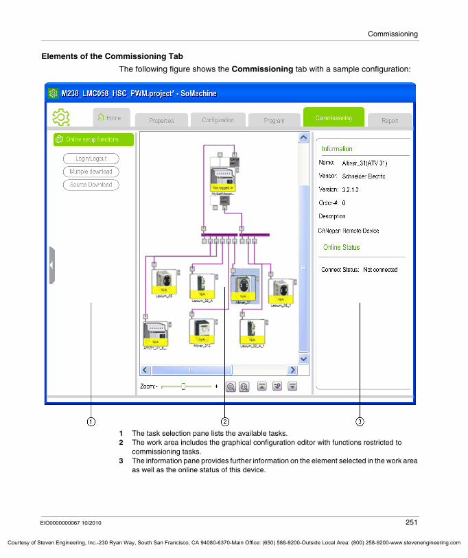
Commissioning
Courtesy o
Elements of the Commissioning Tab
The following figure shows the Commissioning tab with a sample configuration:
1 The task selection pane lists the available tasks.2 The work area includes the graphical configuration editor with functions restricted to
commissioning tasks.3 The information pane provides further information on the element selected in the work area
as well as the online status of this device.
EIO0000000067 10/2010 251
f Steven Engineering, Inc.-230 Ryan Way, South San Francisco, CA 94080-6370-Main Office: (650) 588-9200-Outside Local Area: (800) 258-9200-www.stevenengineering.com
Commissioning
Courtesy of St
Online Status Information
The online status is indicated in the graphical configuration editor for each device individually in different colors:
The online status information is displayed in the information pane for the device selected in the graphical configuration editor.
Editing Device and Communication Parameters
To edit device parameters for commissioning the machinedouble-click the device icon in the graphical configuration editor orright-click the device icon and select Edit parameters from the context menu.
Result: The Parameters configuration screen will be displayed for the selected device (see page 70).
To edit communication parameters for commissioning the machinedouble-click the network connection line in the graphical configuration editor orright-click the network connection line and select Edit parameters from the context menu.
Result: The network configuration screen will be displayed for the selected network connection (see page 84).
NOTE: See the Programming Guide for your controller for important safety-related information concerning the editing of device and communication parameters.
Online Status Color
Not logged in yellow
Running green
Stopped red
252 EIO0000000067 10/2010
even Engineering, Inc.-230 Ryan Way, South San Francisco, CA 94080-6370-Main Office: (650) 588-9200-Outside Local Area: (800) 258-9200-www.stevenengineering.com
Commissioning
Courtesy o
Description of the Login/Logout Task
Overview
The Login/Logout task allows you to establish a connection between your PC running SoMachine and a connected device for uploading / downloading software.
Before you can establish this connection you must physically connect your device to your PC. For detailed information on this hardware connection, refer to the hardware manual of your device.
The login procedure differs depending on whether your project consists of only 1 or of several applications.
Login Procedure with Project Consisting of 1 Controller with 1 Application
For login to a connected device, proceed as follows:
To log out, click the Login/Logout button in the task selection pane once again.
Result: After successful logout, the information line at the bottom of each device icon will get the status not logged in or N/A with color yellow.
WARNINGUNINTENDED EQUIPMENT OPERATION
Whenever you login to your controller, ensure the following:Confirm you have entered the correct device designation or device address.Guards must be in place so that unintended equipment operation will not cause injury to personnel or damage to equipment.You must have read and understood the user documentation of the software and devices involved and must know how to operate the equipment.
Failure to follow these instructions can result in death, serious injury, or equipment damage.
Step Action
1 In the Commissioning tab click the Login/Logout button from the task selection pane.Result: After successful login, the information line at the bottom of each device icon will indicate the status of the device using different colors (for example, Stop is indicated in red).
EIO0000000067 10/2010 253
f Steven Engineering, Inc.-230 Ryan Way, South San Francisco, CA 94080-6370-Main Office: (650) 588-9200-Outside Local Area: (800) 258-9200-www.stevenengineering.com
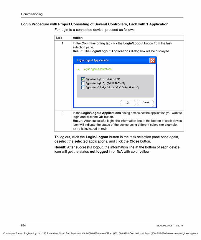
Commissioning
Courtesy of St
Login Procedure with Project Consisting of Several Controllers, Each with 1 Application
For login to a connected device, proceed as follows:
To log out, click the Login/Logout button in the task selection pane once again, deselect the selected applications, and click the Close button.
Result: After successful logout, the information line at the bottom of each device icon will get the status not logged in or N/A with color yellow.
Step Action
1 In the Commissioning tab click the Login/Logout button from the task selection pane.Result: The Login/Logout Applications dialog box will be displayed.
2 In the Login/Logout Applications dialog box select the application you want to login and click the OK button.Result: After successful login, the information line at the bottom of each device icon will indicate the status of the device using different colors (for example, Stop is indicated in red).
254 EIO0000000067 10/2010
even Engineering, Inc.-230 Ryan Way, South San Francisco, CA 94080-6370-Main Office: (650) 588-9200-Outside Local Area: (800) 258-9200-www.stevenengineering.com
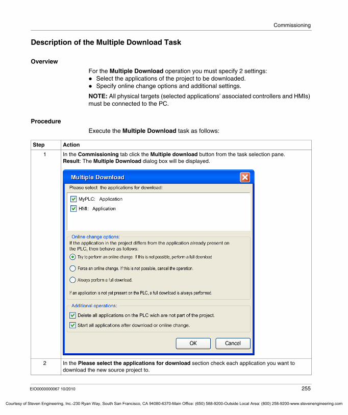
Commissioning
Courtesy o
Description of the Multiple Download Task
Overview
For the Multiple Download operation you must specify 2 settings:Select the applications of the project to be downloaded.Specify online change options and additional settings.
NOTE: All physical targets (selected applications’ associated controllers and HMIs) must be connected to the PC.
Procedure
Execute the Multiple Download task as follows:
Step Action
1 In the Commissioning tab click the Multiple download button from the task selection pane.Result: The Multiple Download dialog box will be displayed.
2 In the Please select the applications for download section check each application you want to download the new source project to.
EIO0000000067 10/2010 255
f Steven Engineering, Inc.-230 Ryan Way, South San Francisco, CA 94080-6370-Main Office: (650) 588-9200-Outside Local Area: (800) 258-9200-www.stevenengineering.com
Commissioning
Courtesy of St
NOTE: See the Programming Guide for your controller for important safety-related information concerning the Multiple Download feature.
3 Select the Online change options that suit your application. For further details refer to the CoDeSys part of the online help.
4 Select the Additional operations options that suit your application. For further details refer to the CoDeSys part of the online help.
5 Click the OK button to start the download process.Result: A Multiple Download - Result message box will be displayed indicating for each application if the download process has been successfully completed.
Step Action
256 EIO0000000067 10/2010
even Engineering, Inc.-230 Ryan Way, South San Francisco, CA 94080-6370-Main Office: (650) 588-9200-Outside Local Area: (800) 258-9200-www.stevenengineering.com
Commissioning
Courtesy o
Description of the Source Download Task
Overview
The Source Download task allows you to download an archived version of a SoMachine project from your PC to a connected controller.
NOTE: Please note that an additional memory card must be available on the controller to use this function. It is thus only available for ATV IMC and M258 controllers as well as for those XBTGC types that can use a USB flash drive as secondary storage. XBTGT/GK controllers can use the CF card as secondary storage for source download with SoMachine 2.0.
Procedure
To download a SoMachine project to your controller, proceed as follows:
Step Action
1 Login to the controller you want to download the SoMachine project to, as described in the Description of the Login / Logout Task chapter (see page 253).
2 Click the Source Download button from the task selection pane.Result: A project archive of the currently open project is automatically created and downloaded to the controller.
EIO0000000067 10/2010 257
f Steven Engineering, Inc.-230 Ryan Way, South San Francisco, CA 94080-6370-Main Office: (650) 588-9200-Outside Local Area: (800) 258-9200-www.stevenengineering.com

Commissioning
258 EIO0000000067 10/2010
Courtesy of Steven Engineering, Inc.-230 Ryan Way, South San Francisco, CA 94080-6370-Main Office: (650) 588-9200-Outside Local Area: (800) 258-9200-www.stevenengineering.com
EIO0000000067 10/2010
Courtesy of Steven Engineering, Inc.-230 Ryan Way, South San Francisco, CA 94080-6370-Main Office: (650) 588-9200-Outside Local Ar
9
Report
EIO0000000067 10/2010
Report
Report
The Report Tab
The Report tab is only available after you have opened a SoMachine project.
It provides tasks to create and customize a report of your project.
The Task Selection Pane on the left shows the report creation steps:Print PreviewPrint
Elements of the Report Tab
This tab also provides the Customization task to adapt your report to your individual preferences.
259
ea: (800) 258-9200-www.stevenengineering.com
Report
Courtesy of St
The figure below shows the elements of the Report tab:
1 tasks for the report creation2 tree structure of your project for selection3 task for report customization
Buttons of the Report Tab
The buttons in the work area allow you to view a tree structure of your project and to arrange the items within this structure. Each item of your project provides a check box. Select the check boxes of the items you want to be part of your report.
Buttons for Report Settings Meaning
Move Up Click Move Up to move an item of your project upwards in the tree structure of your project.
Move Down Click Move Down to move an item downwards in the tree structure of your project.
Select All
Click Select All to select the check boxes of all your project items
Select None
Click Select None to unmark the check boxes of all your project items
260 EIO0000000067 10/2010
even Engineering, Inc.-230 Ryan Way, South San Francisco, CA 94080-6370-Main Office: (650) 588-9200-Outside Local Area: (800) 258-9200-www.stevenengineering.com
Report
Courtesy o
Printing a Report
To print out your report, proceed as follows:
For page setup use the Windows print dialog box.
Expand All
Click Expand All to unfold the details of the tree structure of all your project items
Collapse All
Click Collapse All to close the view of the tree structure.
Buttons for Report Settings Meaning
Step Action
1 Click Print Preview to have a view of the items you have selected. Result: A Print Preview is generated. To page up or page down in your preview, click on the right side of the page number displayed in the task bar of the Print Preview box.
2 Click Print to start printing.Result: A Windows dialog box for Print opens.Select your settings and click OK to start printing.
EIO0000000067 10/2010 261
f Steven Engineering, Inc.-230 Ryan Way, South San Francisco, CA 94080-6370-Main Office: (650) 588-9200-Outside Local Area: (800) 258-9200-www.stevenengineering.com
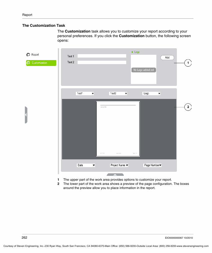
Report
Courtesy of St
The Customization Task
The Customization task allows you to customize your report according to your personal preferences. If you click the Customization button, the following screen opens:
1 The upper part of the work area provides options to customize your report.2 The lower part of the work area shows a preview of the page configuration. The boxes
around the preview allow you to place information in the report.
262 EIO0000000067 10/2010
even Engineering, Inc.-230 Ryan Way, South San Francisco, CA 94080-6370-Main Office: (650) 588-9200-Outside Local Area: (800) 258-9200-www.stevenengineering.com
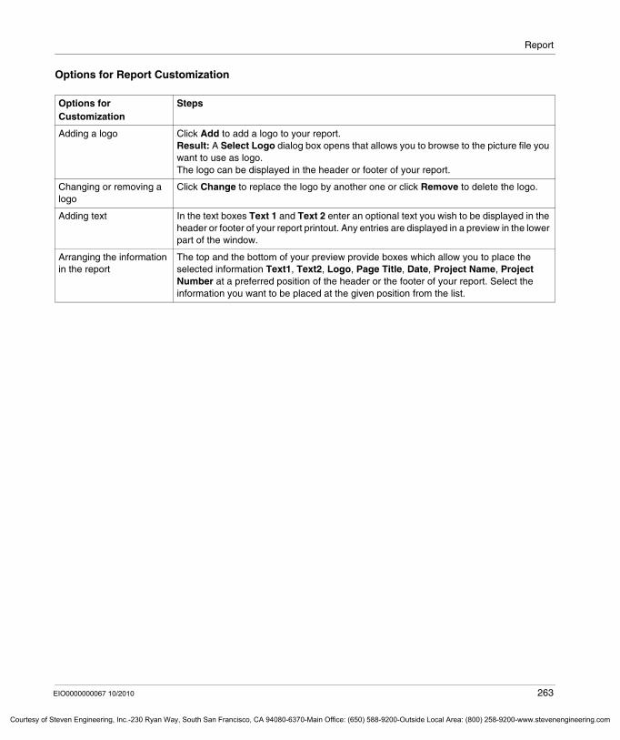
Report
Courtesy o
Options for Report Customization
Options for Customization
Steps
Adding a logo Click Add to add a logo to your report.Result: A Select Logo dialog box opens that allows you to browse to the picture file you want to use as logo.The logo can be displayed in the header or footer of your report.
Changing or removing a logo
Click Change to replace the logo by another one or click Remove to delete the logo.
Adding text In the text boxes Text 1 and Text 2 enter an optional text you wish to be displayed in the header or footer of your report printout. Any entries are displayed in a preview in the lower part of the window.
Arranging the information in the report
The top and the bottom of your preview provide boxes which allow you to place the selected information Text1, Text2, Logo, Page Title, Date, Project Name, Project Number at a preferred position of the header or the footer of your report. Select the information you want to be placed at the given position from the list.
EIO0000000067 10/2010 263
f Steven Engineering, Inc.-230 Ryan Way, South San Francisco, CA 94080-6370-Main Office: (650) 588-9200-Outside Local Area: (800) 258-9200-www.stevenengineering.com

Report
264 EIO0000000067 10/2010
Courtesy of Steven Engineering, Inc.-230 Ryan Way, South San Francisco, CA 94080-6370-Main Office: (650) 588-9200-Outside Local Area: (800) 258-9200-www.stevenengineering.com

EIO0000000067 10/2010
Courtesy of Steven Engineering, Inc.-230 Ryan Way, South San Francisco, CA 94080-6370-Main Office: (650) 588-9200-Outside Local Ar
III
Troubleshooting and FAQ
EIO0000000067 10/2010
Troubleshooting and FAQ
265
ea: (800) 258-9200-www.stevenengineering.com

Troubleshooting and FAQ
266 EIO0000000067 10/2010
Courtesy of Steven Engineering, Inc.-230 Ryan Way, South San Francisco, CA 94080-6370-Main Office: (650) 588-9200-Outside Local Area: (800) 258-9200-www.stevenengineering.com
EIO0000000067 10/2010
Courtesy of Steven Engineering, Inc.-230 Ryan Way, South San Francisco, CA 94080-6370-Main Office: (650) 588-9200-Outside Local Ar
10
Generic - Troubleshooting and FAQ
EIO0000000067 10/2010
Generic - Troubleshooting and FAQ
10.1 Frequently Asked Questions
What's in this Section?
This section contains the following topics:
Topic Page
Shortcuts and Menus 268
Enabling and Configuring Analog Inputs on CANopen 270
267
ea: (800) 258-9200-www.stevenengineering.com
Generic - Troubleshooting and FAQ
Courtesy of St
Shortcuts and Menus
Overview
The menus and shortcuts of the SoMachine software differ depending on the actual position, that is the window or editor that is currently open.
The menus and shortcuts of the SoMachine graphical user interface are optimized for SoMachine but you can adapt them to your individual preferences or you can load the CoDeSys standard shortcuts and menus.
Customizing Shortcuts and Menus
You can adapt the shortcuts and menus to your individual preferences by using the Tools → Customize menu.
Restoring the SoMachine Standard Shortcuts and Menus
To restore the SoMachine standard shortcuts and menus (after you have customized them), proceed as follows:
Setting the Shortcuts and Menus to CoDeSys Standard
To import the CoDeSys shortcuts and menus to your SoMachine graphical user interface, proceed as follows:
Step Action
1 Execute the Customize command from the Tools menu.Result: The Customize dialog box will be displayed.
2 In the Customize dialog box click the Load button.Result: The Load Menu dialog box will be displayed.
3 In the Load Menu dialog box navigate to the folder ...\Program Files\Schneider Electric\SoMachine\CoDeSys\Settings, select the file Standard.opt.menu and click Open.Result: The Customize dialog box now shows the standard SoMachine settings.
4 To load these standard settings to the SoMachine graphical user interface, click OK.
Step Action
1 Execute the Customize command from the Tools menu.Result: The Customize dialog box will be displayed.
2 In the Customize dialog box click the Load button.Result: The Load Menu dialog box will be displayed.
268 EIO0000000067 10/2010
even Engineering, Inc.-230 Ryan Way, South San Francisco, CA 94080-6370-Main Office: (650) 588-9200-Outside Local Area: (800) 258-9200-www.stevenengineering.com
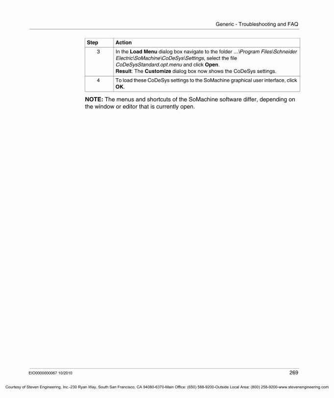
Generic - Troubleshooting and FAQ
Courtesy o
NOTE: The menus and shortcuts of the SoMachine software differ, depending on the window or editor that is currently open.
3 In the Load Menu dialog box navigate to the folder ...\Program Files\Schneider Electric\SoMachine\CoDeSys\Settings, select the file CoDeSysStandard.opt.menu and click Open.Result: The Customize dialog box now shows the CoDeSys settings.
4 To load these CoDeSys settings to the SoMachine graphical user interface, click OK.
Step Action
EIO0000000067 10/2010 269
f Steven Engineering, Inc.-230 Ryan Way, South San Francisco, CA 94080-6370-Main Office: (650) 588-9200-Outside Local Area: (800) 258-9200-www.stevenengineering.com
Generic - Troubleshooting and FAQ
Courtesy of St
Enabling and Configuring Analog Inputs on CANopen
Overview
This section provides instructions on enabling analog inputs according to the CANopen standard by setting the SDO (Service Data Object) 6423 to the value 1.
Procedure
Step Action
1 Double-click the entry of your analog CANopen device in the Devices window.
2 In the CANopen Remote Device tab, enable the option Enable Expert PDO Settings.Result: Additional tabs are displayed and the Service Data Object tab is populated with information.
270 EIO0000000067 10/2010
even Engineering, Inc.-230 Ryan Way, South San Francisco, CA 94080-6370-Main Office: (650) 588-9200-Outside Local Area: (800) 258-9200-www.stevenengineering.com
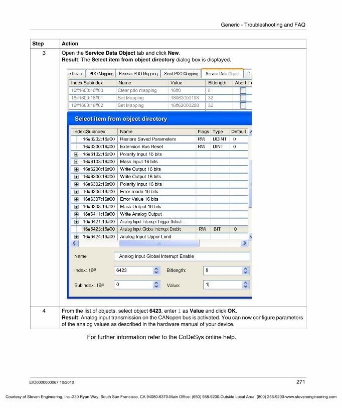
Generic - Troubleshooting and FAQ
Courtesy o
For further information refer to the CoDeSys online help.
3 Open the Service Data Object tab and click New.Result: The Select item from object directory dialog box is displayed.
4 From the list of objects, select object 6423, enter 1 as Value and click OK.Result: Analog input transmission on the CANopen bus is activated. You can now configure parameters of the analog values as described in the hardware manual of your device.
Step Action
EIO0000000067 10/2010 271
f Steven Engineering, Inc.-230 Ryan Way, South San Francisco, CA 94080-6370-Main Office: (650) 588-9200-Outside Local Area: (800) 258-9200-www.stevenengineering.com

Generic - Troubleshooting and FAQ
272 EIO0000000067 10/2010
Courtesy of Steven Engineering, Inc.-230 Ryan Way, South San Francisco, CA 94080-6370-Main Office: (650) 588-9200-Outside Local Area: (800) 258-9200-www.stevenengineering.com
Courtesy
Glossary
EIO0000000067 10/2010
o
Glossary
0-9
%IAccording to the IEC standard, %I represents an input bit (for example a language object of type digital IN).
%IWAccording to the IEC standard, %IW represents an input word register (for example a language object of type analog IN).
%MWAccording to the IEC standard, %MW represents a memory word register (for example a language object of type memory word).
%QAccording to the IEC standard, %Q represents an output bit (for example a language object of type digital OUT).
%QWAccording to the IEC standard, %QW represents an output word register (for example a language object of type analog OUT).
1-phase counterA 1-phase counter uses 1 hardware input as counter input. It usually counts up or counts down when there is pulse signal in the input.
EIO0000000067 10/2010 273
f Steven Engineering, Inc.-230 Ryan Way, South San Francisco, CA 94080-6370-Main Office: (650) 588-9200-Outside Local Area: (800) 258-9200-www.stevenengineering.com
Glossary
Courtesy of St
2-phase counterA 2-phase counter uses the phase difference between 2 input counter signals to count up or count down.
A
AFBapplication function block
analog inputAn analog input module contains circuits that convert an analog DC input signal to a digital value that can be manipulated by the processor. By implication, the analog input is usually direct. That means a data table value directly reflects the analog signal value.
analog outputAn analog output module contains circuits that transmit an analog DC signal proportional to a digital value input to the module from the processor. By implication, these analog outputs are usually direct. That means a data table value directly controls the analog signal value.
application sourceThe application source file can be uploaded to the PC to reopen a SoMachine project. This source file can support a full SoMachine project (for example, one that includes HMI application).
ARPThe address resolution protocol is the IP network layer protocol for Ethernet that maps an IP address to a MAC (hardware) address.
ARRAYAn ARRAY is a table containing elements of a single type. The syntax is as follows: ARRAY [<limits>] OF <Type>
Example 1: ARRAY [1..2] OF BOOL is a 1-dimensional table with 2 elements of type BOOL.
Example 2: ARRAY [1..10, 1..20] OF INT is a 2-dimensional table with 10x20 elements of type INT.
274 EIO0000000067 10/2010
even Engineering, Inc.-230 Ryan Way, South San Francisco, CA 94080-6370-Main Office: (650) 588-9200-Outside Local Area: (800) 258-9200-www.stevenengineering.com
Glossary
Courtesy o
ARWanti-reset windup
ASCIIThe american standard code for information interchange is a communication protocol for representing alphanumeric characters (letters, numbers, and certain graphic and control characters).
assigned variableA variable is "assigned" if its location in controller memory can be known. For example, the Water_pressure variable is said to be assigned through its association with memory location %MW102.Water_pressure.
ATCanalog tension control
ATVATV is the model prefix for Altivar drives. (For example, “ATV312” refers to the Altivar 312 variable speed drive.)
AWGThe american wire gauge standard specifies wire gauges in North America.
B
BCDThe binary coded decimal format represents decimal numbers between 0 and 9 with a set of 4 bits (a nybble/nibble, also titled as Halfbyte). In this format, the 4 bits used to encode decimal numbers have an unused range of combinations. For example, the number 2,450 is encoded as 0010 0100 0101 0000
BOOLA Boolean type is the basic data type in computing. A BOOL variable can have one of these values: 0 (FALSE), 1 (TRUE). A bit that is extracted from a word is of type BOOL, for example: %MW10.4 is a fifth bit a memory word number 10.
EIO0000000067 10/2010 275
f Steven Engineering, Inc.-230 Ryan Way, South San Francisco, CA 94080-6370-Main Office: (650) 588-9200-Outside Local Area: (800) 258-9200-www.stevenengineering.com
Glossary
Courtesy of St
Boot applicationFiles that contain machine dependent parameters:
machine namedevice name or IP addressModbus Serial Line addressRouting table
BOOTPThe bootstrap protocol is a UDP network protocol that can be used by a network client to automatically obtain an IP address (and possibly other data) from a server. The client identifies itself to the server using the client MAC address. The server—which maintains a pre-configured table of client device MAC addresses and associated IP addresses—sends the client its pre-configured IP address. BOOTP was originally used as a method that enabled diskless hosts to be remotely booted over a network. The BOOTP process assigns an infinite lease of an IP address. The BOOTP service utilizes UDP ports 67 and 68.
bpsbit per second as a definition of transmission rate, also given in conjunction with multiplicator kilo (kbps) and mega (mbps).
BSHBSH is a Lexium servo motor from Schneider Electric.
bus baseA bus base is a mounting device that is designed to seat an electronic module on a DIN rail and connect it to the TM5 bus for M258 and LMC058 controllers. Each base bus extends the TM5 data and to the power buses and the 24 Vdc I/O power segment. The electronic modules are added to the TM5 system through their insertion on the base bus. The base bus also supplies the articulation point for the terminal blocks.
BYTEWhen 8 bits are grouped together, they are called a BYTE. You can enter a BYTE either in binary mode or in base 8. The BYTE type is encoded in an 8-bit format that ranges from 16#00 to 16#FF (in hexadecimal format).
276 EIO0000000067 10/2010
even Engineering, Inc.-230 Ryan Way, South San Francisco, CA 94080-6370-Main Office: (650) 588-9200-Outside Local Area: (800) 258-9200-www.stevenengineering.com
Glossary
Courtesy o
C
CANThe controller area network protocol (ISO 11898) for serial bus networks is designed for the interconnection of smart devices (from multiple manufacturers) in smart systems for real-time industrial applications. CAN multi-master systems ensure high data integrity through the implementation of broadcast messaging and advanced diagnostic mechanisms. Originally developed for use in automobiles, CAN is now used in a variety of industrial automation control environments.
CANmotionCANmotion is a CANopen-based motion bus with an additional mechanism that provides synchronization between the motion controller and the drives.
CANopenCANopen is an open industry-standard communication protocol and device profile specification.
CFCThe continuous function chart (an extension of the IEC61131-3 standard) is a graphical programming language that works like a flowchart. By adding simple logic blocks (AND, OR, etc.), each function or function block in the program is represented in this graphical format. For each block, the inputs are on the left and the outputs on the right. Block outputs can be linked to inputs of other blocks in order to create complex expressions.
CiACAN in automation is a non-profit group of manufacturers and users dedicated to developing and supporting CAN-based higher layer protocols.
CIPWhen the common industrial protocol is implemented in a network application layer, it can communicate seamlessly with other CIP-based networks without regard to the protocol. For example, the implementation of CIP in the application layer of an Ethernet TCP/IP network creates an EtherNet/IP environment. Similarly, CIP in the application layer of a CAN network creates a DeviceNet environment. In that case, devices on the EtherNet/IP network can communicate with devices on the DeviceNet network through CIP bridges or routers.
EIO0000000067 10/2010 277
f Steven Engineering, Inc.-230 Ryan Way, South San Francisco, CA 94080-6370-Main Office: (650) 588-9200-Outside Local Area: (800) 258-9200-www.stevenengineering.com
Glossary
Courtesy of St
CMUThe current measurement unit is used to convert the relative current value (%) provided by TeSys into a real ISO value (A).
configurationThe configuration includes the arrangement and interconnection of hardware components within a system and the hardware and software selections that determine the operating characteristics of the system.
controllerA controller (or “programmable logic controller,” or “programmable controller”) is used to automate industrial processes.
controller status outputThe controller status output is a special function used in circuits that are external to the controller that control the power supply to the output devices or the controller power supply.
CPDMcontroller power distribution module
CRCA network message's cyclic redundancy check field contains a small number of bits that produce a checksum. The message is calculated by the transmitter according to the message’s content. Receiving nodes then recalculate the field. Any discrepancy in the two CRC fields indicates that the transmitted message and the received message are different.
CSAThe canadian standards association defines and maintains standards for industrial electronic equipment in hazardous environments.
CTSClear to send is a data transmission signal and acknowledges the RDS signal from the transmitting station.
278 EIO0000000067 10/2010
even Engineering, Inc.-230 Ryan Way, South San Francisco, CA 94080-6370-Main Office: (650) 588-9200-Outside Local Area: (800) 258-9200-www.stevenengineering.com
Glossary
Courtesy o
cyclic taskThe cyclic scan time has a fixed duration (interval) specified by the user. If the current scan time is shorter than the cyclic scan time, the controller waits until the cyclic scan time has elapsed before starting a new scan.
D
data logThe controller logs events relative to the user application in a data log.
DCEData communications equipment describes devices (often modems) that start, stop, and sustain network sessions.
DeratingDerating describes a reduction in an operating specification. For devices in general it is usually a specified reduction in nominal power to facilitate operation at increased ambient conditions like higher temperatures or higher altitudes.
DHCPThe dynamic host configuration protocol is an advanced extension of BOOTP. DHCP is a more advanced, but both DHCP and BOOTP are common. (DHCP can handle BOOTP client requests.)
digital I/OA digital input or output has an individual circuit connection at the electronic module that corresponds directly to a data table bit that holds the value of the signal at that I/O circuit. It gives the control logic digital access to I/O values.
DINDeutsches Institut für Normung is a German institution that sets engineering and dimensional standards.
DINTA double integer type is encoded in a 32-bit format.
EIO0000000067 10/2010 279
f Steven Engineering, Inc.-230 Ryan Way, South San Francisco, CA 94080-6370-Main Office: (650) 588-9200-Outside Local Area: (800) 258-9200-www.stevenengineering.com
Glossary
Courtesy of St
DNSThe domain name system is the naming system for computers and devices connected to a LAN or the Internet.
drop cableA drop cable is the unterminated derivation cord used to connect a TAP to a device.
DSRData set ready is a data transmission signal.
DTMWith device type managers representing the field device in SoMachine, direct communications are possible to every single field device via SoMachine, the controller and the field bus, thus avoiding the need for individual cable connections.
DWORDA double word type is encoded in a 32-bit format.
E
EDSElectronic data sheet contains for example the properties of a device e.g. parameters and settings of a drive.
EEPROMElectrically erasable programmable read-only memory is a type of non-volatile memory used to store data that must be saved when power is removed.
EIAThe electronic industries alliance is the trade organization for establishing electrical/electronic and data communication standards (including RS-232 and RS-485) in the United States.
EIA rackAn electronic industries alliance rack is a standardized (EIA 310-D, IEC 60297 and DIN 41494 SC48D) system for mounting various electronic modules in a stack or rack that is 19 inches (482.6 mm) wide.
280 EIO0000000067 10/2010
even Engineering, Inc.-230 Ryan Way, South San Francisco, CA 94080-6370-Main Office: (650) 588-9200-Outside Local Area: (800) 258-9200-www.stevenengineering.com
Glossary
Courtesy o
electronic moduleIn a programmable controller system, most electronic modules directly interface to the sensors, actuators, and external devices of the machine/process. This electronic module is the component that mounts in a bus base and provides electrical connections between the controller and the field devices. Electronic modules are offered in a variety of signal levels and capacities. (Some electronic modules are not I/O interfaces, including power distribution modules and transmitter/receiver modules.)
ENEN identifies one of many European standards maintained by CEN (European Committee for Standardization), CENELEC (European Committee for Electrotechnical Standardization), or ETSI (European Telecommunications Standards Institute).
encoderAn encoder is a device for length or angular measurement (linear or rotary encoders).
EquipmentAn Equipment is a part of the Machine.
ERCeccentric roller conveyor
ESDelectrostatic discharge
EthernetEthernet is a physical and data link layer technology for LANs, also known as IEE 802.3.
EtherNet/IPThe ethernet industrial protocol is an open communications protocol for manufacturing automation solutions in industrial systems. EtherNet/IP is in a family of networks that implements Common Industrial Protocol at its upper layers. The supporting organization (ODVA) specifies EtherNet/IP to accomplish global adaptability and media independence.
EIO0000000067 10/2010 281
f Steven Engineering, Inc.-230 Ryan Way, South San Francisco, CA 94080-6370-Main Office: (650) 588-9200-Outside Local Area: (800) 258-9200-www.stevenengineering.com
Glossary
Courtesy of St
expansion busThe expansion bus is an electronic communication bus between expansion modules and a CPU.
expansion I/O moduleAn expansion input or output module is either a digital or analog module that adds additional I/O to the base controller.
expert I/OExpert I/Os are dedicated modules or channels for advanced features. These features are generally embedded in the module in order to not use the resources of the PLC Controller and to allow a fast response time, depending of the feature. Regarding the function, it could be considered as a “stand alone” module, because the function is independent of the Controller processing cycle, it just exchanges some information with the Controller CPU.
F
FAST I/OFAST I/Os are specific I/Os with some electrical features (response time, for example) but the treatment of these channels is done by the Controller CPU.
FAST taskThe FAST task is a periodic, high-priority task of a short duration that is run on a processor through its programming software. The task fast speed keeps it from interfering with the execution of lower priority master (MAST) tasks. A FAST task is useful when fast periodic changes in discrete inputs need to be monitored.
FBA function block performs a specific automation function, such as speed control, interval control, or counting. A function block comprises configuration data and a set of operating parameters.
FBDA function block diagram is a graphically oriented programming language, compliant with IEC 61131-3. It works with a list of networks whereby each network contains a graphical structure of boxes and connection lines which represents either a logical or arithmetic expression, the call of a function block, a jump, or a return instruction.
282 EIO0000000067 10/2010
even Engineering, Inc.-230 Ryan Way, South San Francisco, CA 94080-6370-Main Office: (650) 588-9200-Outside Local Area: (800) 258-9200-www.stevenengineering.com
Glossary
Courtesy o
FDTField device tool for standardized communications between field devices and SoMachine.
FEFunctional ground is the point of a system or device that must be grounded to help prevent equipment damage.
FGfrequency generator
firmwareThe firmware represents the operating system on a controller.
Flash memoryFlash memory is nonvolatile memory that can be overwritten. It is stored on a special EEPROM that can be erased and reprogrammed.
FTPFile transfer protocol is a standard network protocol (built on a client-server architecture), to exchange and manipulate files over TCP/IP based networks.
functionA function:
is a POU that returns 1 immediate resultis directly called with its name (as opposed to through an instance)has no persistent state from one call to the nextcan be used as an operand in expressions
Examples: boolean (AND) operators, calculations, conversions (BYTE_TO_INT)
function block (FB)See FB.
function block diagram (FBD)See FBD.
FWDforward
EIO0000000067 10/2010 283
f Steven Engineering, Inc.-230 Ryan Way, South San Francisco, CA 94080-6370-Main Office: (650) 588-9200-Outside Local Area: (800) 258-9200-www.stevenengineering.com
Glossary
Courtesy of St
G
GVLThe global variable list manages global variables that are available in every application POU.
H
HE10Rectangular connector for electrical signals with frequencies below 3MHz, complying with IEC60807-2.
HMIA human-machine interface is an operator interface (usually graphical) for industrial equipment.
hot swappingHot swapping is the replacement of a component with a like component while the system remains operational. The replacement component begins to function automatically after it is installed.
HSChigh-speed counter
HVACHeating ventilation and air conditioning applications monitor and control indoor environments.
I
I/Oinput/output
284 EIO0000000067 10/2010
even Engineering, Inc.-230 Ryan Way, South San Francisco, CA 94080-6370-Main Office: (650) 588-9200-Outside Local Area: (800) 258-9200-www.stevenengineering.com
Glossary
Courtesy o
I/O scanAn input/output scan continuously polls I/O modules to collect data bits and status, error, and diagnostics information. This process monitors inputs and controls outputs.
I/O terminalAn input/output terminal on the front of an expansion I/O module connects input and output signals.
ICMPThe internet control message protocol reports errors and provides information related to datagram processing.
IECThe international electrotechnical commission is a non-profit and non-governmental international standards organization that prepares and publishes international standards for all electrical, electronic, and related technologies.
IEC 61131-3The IEC 61131-3 is an international electrotechnical commission standard for industrial automation equipment (like controllers). IEC 61131-3 deals with controller programming languages and defines 2 graphical and 2 textual programming language standards:
graphical: ladder diagram, function block diagramtextual: structured text, instruction list
IEEEThe institute of electrical and electronics engineers is a non-profit international standards and conformity assessment body for advances in all fields of electrotechnology.
IEEE 802.3IEEE 802.3 is a collection of IEEE standards defining the physical layer, and the media access control (MAC) sublayer of the data link layer, of wired Ethernet.
ILA program written in the instruction list language is composed of a series of instructions executed sequentially by the controller. Each instruction includes a line number, an instruction code, and an operand. (IL is IEC 61131-3 compliant.)
EIO0000000067 10/2010 285
f Steven Engineering, Inc.-230 Ryan Way, South San Francisco, CA 94080-6370-Main Office: (650) 588-9200-Outside Local Area: (800) 258-9200-www.stevenengineering.com
Glossary
Courtesy of St
immediate addressingThe direct method of addressing memory objects, including physical inputs and outputs, used in programming instructions as operands and parameters by using their direct address (for example, %Iwx or %QWx).
The use of immediate addressing in your program may avoid the need to create symbols for these objects, but there are also disadvantages. For example, if you change the program configuration by adding or deleting devices or I/O modules or slices, the immediate addresses used as programming instruction operands and/or parameters are not updated and must be corrected manually, which may cause extensive program modifications and lead to incorrect programming instructions. (See symbolic addressing.)
input filterAn input filter is a special function that rejects input noises. It is useful for eliminating input noises and chatter in limit switches. All inputs provide a level of input filtering using the hardware. Additional filtering with software is also configurable through the programing or the configuration software.
input terminalAn input terminal on the front of an expansion I/O module connects input signals from input devices (such as sensors, push buttons, and limit switches). For some modules, input terminals accept both sink and source DC input signals.
instruction list language (IL)Refer to IL.
INTA single integer is encoded in 16 bits.
IPThe internet protocol is part of the TCP/IP protocol family that tracks the Internet addresses of devices, routes outgoing messages, and recognizes incoming messages.
IP 20Ingress protection rating according to IEC 60529. IP20 modules are protected against ingress and contact of objects larger than 12.5 mm. The module is not protected against harmful ingress of water.
286 EIO0000000067 10/2010
even Engineering, Inc.-230 Ryan Way, South San Francisco, CA 94080-6370-Main Office: (650) 588-9200-Outside Local Area: (800) 258-9200-www.stevenengineering.com
Glossary
Courtesy o
IP 67Ingress protection rating according to IEC 60529. IP67 modules are completely protected against ingress of dust and contact. Ingress of water in harmful quantity is not possible when the enclosure is immersed in water up to 1m.
K
Kdderivative gain
Kiintegral gain
Kpproportional gain
L
Ladder Diagram languageSee LD.
LANA local area network local area network is a short-distance communications network that is implemented in a home, office, or institutional environment.
latching inputA latching input module interfaces with devices that transmit messages in short pulses. Incoming pulses are captured and recorded for later examination by the application.
LCDliquid crystal display
LDA program in the ladder diagram language includes a graphical representation of instructions of a controller program with symbols for contacts, coils, and blocks in a series of rungs executed sequentially by a controller. IEC 61131-3 compliant.
EIO0000000067 10/2010 287
f Steven Engineering, Inc.-230 Ryan Way, South San Francisco, CA 94080-6370-Main Office: (650) 588-9200-Outside Local Area: (800) 258-9200-www.stevenengineering.com
Glossary
Courtesy of St
LEDA light emitting diode is an indicator that lights up when electricity passes through it.
LINTLong integer is a 64-bit variable (4 times INT or two times DINT).
LMClexium motion control
located variableA located variable has an address. (See unlocated variable.)
LRClongitudinal redundancy checking
LREALLong real is a 64-bit variable.
LSBThe least significant bit (or least significant byte) is the part of a number, address, or field that is written as the right-most single value in conventional hexadecimal or binary notation.
LWORDA long word type is encoded in a 64-bit format.
M
MAC addressThe media access control address is a unique 48-bit number associated with a specific piece of hardware. The MAC address is programmed into each network card or device when it is manufactured.
MachineA Machine consists of several functions and/or equipments which build the machine.
288 EIO0000000067 10/2010
even Engineering, Inc.-230 Ryan Way, South San Francisco, CA 94080-6370-Main Office: (650) 588-9200-Outside Local Area: (800) 258-9200-www.stevenengineering.com
Glossary
Courtesy o
MagelisMagelis is the commercial name for Schneider Electric's range of HMI terminals.
MASTA master (MAST) task is a processor task that is run through its programming software. The MAST task has two sections:
IN: Inputs are copied to the IN section before execution of the MAST task.OUT: Outputs are copied to the OUT section after execution of the MAST task.
master/slaveThe single direction of control in a network that implements the master/slave model is always from a master device or process to one or more slave devices.
MIBThe management information base is an object database that is monitored by a network management system like SNMP. SNMP monitors devices that are defined by their MIBs. Schneider has obtained a private MIB, groupeschneider (3833).
minimum I/O update timeThe minimum I/O update time is the minimum time it takes for the bus cycle to shut down to force an I/O update at each cycle.
ModbusThe Modbus communication protocol allows communications between many devices connected to the same network.
Modbus SLModbus serial line
MSBThe most significant bit (or most significant byte) is the part of a number, address, or field that is written as the left-most single value in conventional hexadecimal or binary notation.
EIO0000000067 10/2010 289
f Steven Engineering, Inc.-230 Ryan Way, South San Francisco, CA 94080-6370-Main Office: (650) 588-9200-Outside Local Area: (800) 258-9200-www.stevenengineering.com
Glossary
Courtesy of St
N
NAKnegative acknowledge
NCA normally closed contact is a contact pair that is closed when the actuator is de-energized (no power is applied) and open when the actuator is energized (power is applied).
NECThe national electric code dictates the safe installation of electrical wiring and equipment.
NEMAThe national electrical manufacturers association publishes standards for the performance of various classes of electrical enclosures. The NEMA standards cover corrosion resistance, ability to protect from rain and submersion, etc. For IEC member countries, the IEC 60529 standard classifies the ingress protection rating for enclosures.
networkA network includes interconnected devices that share a common data path and protocol for communications.
NibbleA Nibble is a half-byte (representing 4 bits of a byte).
NMTNetwork management protocols provide services for network initialization, error control, and device status control.
290 EIO0000000067 10/2010
even Engineering, Inc.-230 Ryan Way, South San Francisco, CA 94080-6370-Main Office: (650) 588-9200-Outside Local Area: (800) 258-9200-www.stevenengineering.com
Glossary
Courtesy o
NMT state machineA network management state machine defines the communication behavior of any CANopen device. The CANopen NMT state machine consists of an initialization state, a pre-operational state, an Operational state, and a stopped state. After power-on or reset, the device enters the initialization state. After the device initialization is finished, the device automatically enters the pre-operational state and announces the state transition by sending the boot-up message. In this manner, the device indicates that it is ready to work. A device that stays in pre-operational state may start to transmit SYNC-, Time Stamp-, or Heartbeat message. In this state, the device can not communicate through a PDO; it must do so with an SDO. In the operational state, the device can use all supported communication objects.
NOA normally open contact is a contact pair that is open when the actuator is de-energized (no power is applied) and closed when the actuator is energized (power is applied).
nodeA node is an addressable device on a communication network.
O
ODVAThe open deviceNet vendors association supports the family of network technologies that are built on CIP (EtherNet/IP, DeviceNet, and CompoNet).
OSOperating system. Can be used for Firmware that can be uploaded/downloaded by the user.
OSIThe open system interconnection reference model is a 7-layer model that describes network protocol communications. Each abstract layer receives services from the layer below it and provides services to the layer above.
OTBOptimized terminal block, used in the context of Advantys I/O distributed module
EIO0000000067 10/2010 291
f Steven Engineering, Inc.-230 Ryan Way, South San Francisco, CA 94080-6370-Main Office: (650) 588-9200-Outside Local Area: (800) 258-9200-www.stevenengineering.com
Glossary
Courtesy of St
output terminalAn output terminal connects output signals to output devices (such as electrome-chanical relays and solenoid valves).
P
palletA pallet is a portable platform, which is used for storing or moving goods.
PCIA peripheral component interconnect is an industry-standard bus for attaching peripherals.
PDMA power distribution module distributes either AC or DC field power to a cluster of I/O modules.
PDOA process data object is transmitted as an unconfirmed broadcast message or sent from a producer device to a consumer device in a CAN-based network. The transmit PDO from the producer device has a specific identifier that corresponds to the receive PDO of the consumer devices.
PDUprotocol data unit
PEProtective ground is a return line across the bus for fault currents generated at a sensor or actuator device in the control system.
periodic executionThe master task is executed either cyclically or periodically. In periodic mode, you determine a specific time (period) in which the master task must be executed. If it is executed under this time, a waiting time is generated before the next cycle. If it is executed over this time, a control system indicates the overrun. If the overrun is too high, the controller is stopped.
292 EIO0000000067 10/2010
even Engineering, Inc.-230 Ryan Way, South San Francisco, CA 94080-6370-Main Office: (650) 588-9200-Outside Local Area: (800) 258-9200-www.stevenengineering.com
Glossary
Courtesy o
persistent dataValue of persistent data that will be used at next application change or cold start. Only get re-initialized at a reboot of the controller or reset origin. Especially they maintain their values after a download.
PIproportional integral
PIDproportional, integral and derivative control
PLCThe programmable logic controller is the “brain” of an industrial manufacturing process. It automates a process, used instead of relay control systems. PLCs are computers suited to survive the harsh conditions of the industrial environment.
PLCopenThe PLCopen standard brings efficiency, flexibility, and manufacturer independence to the automation and control industry through the standardization of tools, libraries, and modular approaches to software programming.
PLIpulse latch input
post-configurationPost-configuration files contain machine-independent parameters, including:
machine namedevice name or IP addressModbus serial line addressrouting table
POUA program organization unit includes a variable declaration in source code and the corresponding instruction set. POUs facilitate the modular reuse of software programs, functions, and function blocks. Once declared, POUs are available to one another. SoMachine programming requires the utilization of POUs.
EIO0000000067 10/2010 293
f Steven Engineering, Inc.-230 Ryan Way, South San Francisco, CA 94080-6370-Main Office: (650) 588-9200-Outside Local Area: (800) 258-9200-www.stevenengineering.com
Glossary
Courtesy of St
POU FBProgram organization unit function block types are user programs that can be defined by the user in the ST, IL, LD, or FBD languages. You can use POU FB types in an application to:
simplify the design and entry of the programmake the program easier to readsimplify debuggingreduce the amount of generated code
power supply terminalsThe power supply is connected to these terminals to provide power to the controller.
protocolA protocol is a convention or standard that controls or enables the connection, communication, and data transfer between two computing endpoints.
Pt100/Pt1000Platinum resistance thermometer are characterized by their nominal resistance R0 at a temperature of 0° C.
Pt100 (R0 = 100 Ohm)Pt1000 (R0 = 1 kOhm)
PTOPulse train outputs are used to control for instance stepper motors in open loop.
PWMPulse width modulation is used for regulation processes (e.g. actuators for temperature control) where a pulse signal is modulated in its length. For these kind of signals, transistor outputs are used.
R
RAMrandom access memory
REALReal is a numeric data type. The REAL type is encoded in a 32-bit format.
294 EIO0000000067 10/2010
even Engineering, Inc.-230 Ryan Way, South San Francisco, CA 94080-6370-Main Office: (650) 588-9200-Outside Local Area: (800) 258-9200-www.stevenengineering.com
Glossary
Courtesy o
real-time clock (RTC)See RTC
reflex outputIn a counting mode, the high speed counter current value is measured against its configured thresholds to determine the state of these dedicated outputs.
retained dataA retained data value is used in the next power-on or warm start. The value is retained even after an uncontrolled shutdown of the controller or a normal switch-off of the controller.
RFIDRadio-frequency identification is an automatic identification method that relies on the storage and remote retrieval of data using RFID tags or transponders.
RJ-45This registered jack is a modular connector that is commonly implemented in communication networks.
RPDOA receive PDO sends data to a device in a CAN-based network.
RPMrevolutions per minute
RPSrevolutions per second
RS-232RS-232 (also known as EIA RS-232C or V.24) is a standard type of serial communication bus, based on three wires.
RS-485RS-485 (also known as EIA RS-485) is a standard type of serial communication bus, based on two wires.
EIO0000000067 10/2010 295
f Steven Engineering, Inc.-230 Ryan Way, South San Francisco, CA 94080-6370-Main Office: (650) 588-9200-Outside Local Area: (800) 258-9200-www.stevenengineering.com
Glossary
Courtesy of St
RTCThe real-time clock option keeps the time for a limited amount of time even when the controller is not powered.
RTSRequest to send is a data transmission signal and will be acknowledged by the CTS signal from the destination node.
RTUA remote terminal unit is a device that interfaces with objects in the physical world to a distributed control system or SCADA system by transmitting telemetry data to the system and/or altering the state of connected objects based on control messages received from the system.
RxDreceiving data (data transmission signal)
S
SCADAA supervisory control and data acquisition system monitors, manages, and controls industrial applications or processes.
scanA controller scanning program performs 3 basic functions: [1] It reads inputs and places these values in memory; [2] it executes the application program 1 instruction at a time and stores results in memory; [3] It uses the results to update outputs.
SDOA service data object message is used by the field bus master to access (read/write) the object directories of network nodes in CAN-based networks. SDO types include service SDOs (SSDOs) and client SDOs (CSDOs).
SEL-VA system that follows IEC 61140 guidelines for safety extra low voltage is protected in such a way that voltage between any 2 accessible parts (or between 1 accessible part and the PE terminal for Class 1 equipment) does not exceed a specified value under normal conditions or under single-fault conditions.
296 EIO0000000067 10/2010
even Engineering, Inc.-230 Ryan Way, South San Francisco, CA 94080-6370-Main Office: (650) 588-9200-Outside Local Area: (800) 258-9200-www.stevenengineering.com
Glossary
Courtesy o
Sequential Function ChartSee SFC.
SFCA program written in the sequential function chart language can be used for processes that can be split into steps. SFC is composed of steps with associated actions, transitions with associated logic condition, and directed links between steps and transitions. (The SFC standard is defined in IEC 848. It is IEC 61131-3 compliant.)
sink inputA sink input is a wiring arrangement in which the device provides current to the input electronic module. A sink input is referenced to 0 Vdc.
SINTSigned integer is a 16-bit value.
SLserial line
SMSThe short message service is a standard communication service for telephones (or other devices) that send short text messages over the mobile communications system.
SNMPThe simple network management protocol can control a network remotely by polling the devices for their status, performing security tests, and viewing information relating to data transmission. It can also be used to manage software and databases remotely. The protocol also permits active management tasks, such as modifying and applying a new configuration
source outputA source output is a wiring arrangement in which the output electronic module provides current to the device. A source output is referenced to +24 Vdc.
SSISerial synchronous interface is a common interface for relative and absolute measurement systems like encoders.
EIO0000000067 10/2010 297
f Steven Engineering, Inc.-230 Ryan Way, South San Francisco, CA 94080-6370-Main Office: (650) 588-9200-Outside Local Area: (800) 258-9200-www.stevenengineering.com
Glossary
Courtesy of St
STSee structured text.
STNScan Twisted Nematic (also known as passive matrix)
STRINGA STRING variable is a series of ASCII characters.
Structured TextA program written in the structured text (ST) language includes complex statements and nested instructions (such as iteration loops, conditional executions, or functions). ST is compliant with IEC 61131-3.
symbolA symbol is a string of a maximum of 32 alphanumeric characters, of which the first character is alphabetic. It allows you to personalize a controller object to facilitate the maintainability of the application.
symbolic addressingThe indirect method of addressing memory objects, including physical inputs and outputs, used in programming instructions as operands and parameters by first defining symbols for them using these symbols in association with the programming instructions.
In contrast to immediate addressing, this is the recommended method because if the program configuration changes, symbols are automatically updated with their new immediate address associations, whereas any immediate addresses used as operands or parameters are not. (See immediate addressing.)
system timeAn internal clock provides a device with the system time.
system variableA system variable structure provides controller data and diagnostic information and allows sending commands to the controller.
298 EIO0000000067 10/2010
even Engineering, Inc.-230 Ryan Way, South San Francisco, CA 94080-6370-Main Office: (650) 588-9200-Outside Local Area: (800) 258-9200-www.stevenengineering.com
Glossary
Courtesy o
T
TAPA terminal access point is a junction box connected to the trunk cable that allows you to plug in drop cables.
taskA group of sections and subroutines, executed cyclically or periodically for the MAST task, or periodically for the FAST task.
A task possesses a level of priority and is linked to inputs and outputs of the controller. These I/O are refreshed in consequence.
A controller can have several tasks.
TCPA transmission control protocol is a connection-based transport layer protocol that provides a reliable simultaneous bi-directional transmission of data. TCP is part of the TCP/IP protocol suite.
terminal blockThe terminal block is the component that mounts in an electronic module and provides electrical connections between the controller and the field devices.
TFTthin film transmission (also known as active matrix)
threshold outputThreshold outputs are controlled directly by the HSC according to the settings established during configuration.
TPA touch probe is a position capture that is triggered by a fast input signal (quick sensor). On the rising edge of the touch probe input the position of an encoder is captured. Example: This is used for packaging machines to capture the position of a printmark on a film to cut always on the same position.
TPDOA transmit PDO reads data from a device in a CAN-based system.
EIO0000000067 10/2010 299
f Steven Engineering, Inc.-230 Ryan Way, South San Francisco, CA 94080-6370-Main Office: (650) 588-9200-Outside Local Area: (800) 258-9200-www.stevenengineering.com
Glossary
Courtesy of St
trunk cableA trunk cable is the main cable that is terminated at both physical ends with line termination resistors.
TVDAtested validated documented architectures
TxDTxD represents a transmit signal.
U
UDINTAn unsigned double integer is encoded in 32 bits.
UDPThe user datagram protocol is a connectionless mode protocol (defined by IETF RFC 768) in which messages are delivered in a datagram (data telegram) to a destination computer on an IP network. The UDP protocol is typically bundled with the Internet Protocol. UDP/IP messages do not expect a response, and are therefore ideal for applications in which dropped packets do not require retransmission (such as streaming video and networks that demand real-time performance).
UINTAn unsigned integer is encoded in 16 bits.
ULUnderwriters Laboratories, US organization for product testing and safety certification.
unlocated variableAn unlocated variable does not have an address. (See located variable.)
UTCcoordinated universal time
300 EIO0000000067 10/2010
even Engineering, Inc.-230 Ryan Way, South San Francisco, CA 94080-6370-Main Office: (650) 588-9200-Outside Local Area: (800) 258-9200-www.stevenengineering.com
Glossary
Courtesy o
V
VSDvariable speed drive
W
WORDThe WORD type is encoded in a 16-bit format.
EIO0000000067 10/2010 301
f Steven Engineering, Inc.-230 Ryan Way, South San Francisco, CA 94080-6370-Main Office: (650) 588-9200-Outside Local Area: (800) 258-9200-www.stevenengineering.com

Glossary
Courtesy of St
302 EIO0000000067 10/2010
even Engineering, Inc.-230 Ryan Way, South San Francisco, CA 94080-6370-Main Office: (650) 588-9200-Outside Local Area: (800) 258-9200-www.stevenengineering.com
Courtesy
Index
EIO0000000067 10/2010
CBA
o
Index
AAdd application, 82adding controllers, 148adding devices, 68analog inputs
CANopen, 270applications, 82AS-Interface, 78AS-Interface configurations, 190ASCII Managers, 186attachments, 59
BBoot Application, 244boot applications, 198Browse for existing project, 27Build All command, 197
CCANopen analog inputs, 270CANopen devices, 152CANopen interface, 180close project, 25closing projects, 23Collapse All, 66command
Build All, 197Export Vijeo-Designer project, 201Import Vijeo-Designer project, 201
EIO0000000067 10/2010
f Steven Engineering, Inc.-230 Ryan Way, South San Francisco, CA 94080-6370-Main Off
commandssingle access, 196
Commission machine - start with project, 43Commission machine - upload project from device, 45Commissioning, 250Communication DTM, 93, 95, 117, 120Communication manager configuration, 152communication managers, 74Configuration, 62configuration diagnostic, 154configuring devices, 70consistency, 84Create Boot Application, 198Create new machine, 32creating libraries, 175Custom Information, 59Customer Service Tool, 257
Ddeleting devices, 68device templates, 225, 226device type managers, 93devices
adding, 154display manager, 66displaying panes, 23DTM, 90, 93
303
ice: (650) 588-9200-Outside Local Area: (800) 258-9200-www.stevenengineering.com
Index
Courtesy of St
EEthernet configurations, 177example projects, 39Expand All, 66Expand Last, 66expansion modules, 78, 149, 150export
Vijeo-Designer projects, 201export command, 201
FFDT, 89, 90, 95, 124field devices configuration, 152fieldbus health information, 154fieldbus manager
adding slave devices, 76Fieldbus Topology, 91fieldbusses supported by templates, 215function templates, 235
Ggeneral functions, 25Generic DTM, 95, 113graphical configuration editor, 66graphical user interface
elements, 23GUI elements, 23
Hhandles, 23Hardwire Topology, 92health information
fieldbus, 154heartbeat settings, 180hiding panes, 23
IIEC Objects
fieldbus Diagnostic/O mapping, 154
304
even Engineering, Inc.-230 Ryan Way, South San Francisco, CA 94080-6370-Main Office
importVijeo-Designer projects, 201
import command, 201information pane, 23
Llanguage setting, 23Learning Center, 50libraries, 159, 162
adding libraries, 137library creation, 175Limitation, 94, 106login, 244Login/Logout, 253
Mmain selection screen, 23menus, 268message window, 23Modbus configurations, 186Modbus IOScanners, 186Modbus Managers, 186Modbus SL devices, 152Multiple Download task, 255
Nnetwork connections, 84Network Managers, 186nodeguarding settings, 180
Oonline help, 23
Pplaceholder concept, 137Preferences, 25Program, 130programming logic, 82projects
close, 23
EIO0000000067 10/2010
: (650) 588-9200-Outside Local Area: (800) 258-9200-www.stevenengineering.com
Index
Courtesy o
Properties tab, 54Protocol Managers, 186publishing variables, 207publishing variables (HMI), 209
RReport tab, 259Reroute, 66Reroute On Drop, 66run, 248
Ssave project, 25saving to USB mass storage device, 199selecting variables, 208Serial Line configurations, 186Set active application, 82shortcuts, 268Show All, 66Show existing machine, 27single access commands, 196slave devices, 76Source Download, 257Start with application, 36Start with empty project, 33Start with Example, 39Start with existing project, 38Start with TVD Architecture, 34startup window, 23stop, 248symbol configuration, 143Synchronized mode, 110
Ttask
Multiple Download, 255task selection pane, 23tasks
adding, 134template libraries, 225templates, 212Topology, 91, 91, 92, 101
EIO0000000067 10/2010
f Steven Engineering, Inc.-230 Ryan Way, South San Francisco, CA 94080-6370-Main Off
transfer, 244Boot Application, 244
TSXCUSB485 cable, 92, 117, 117, 120TVD architecture, 34
UUpdate Device Version, 82Update firmware, 48, 82USB Mass Storage, 199
Vvariable definition, 203variable types, 203variables
persistent, 140publishing, 207publishing (HMI), 209remanent, 140
visualization, 229
Wwork area, 23
305
ice: (650) 588-9200-Outside Local Area: (800) 258-9200-www.stevenengineering.com

Index
306 EIO0000000067 10/2010
Courtesy of Steven Engineering, Inc.-230 Ryan Way, South San Francisco, CA 94080-6370-Main Office: (650) 588-9200-Outside Local Area: (800) 258-9200-www.stevenengineering.com