Embed Size (px)
Citation preview

IOM029FVAE0510
Automation Solutions for oil & gas, defense and aviation applications
Installation and Operations M
anualD
ispatch and Fuels Accounting
4590 Tank Side MonitorField device for tank sensor operation and monitoring and for integration into inventory control systemsSoftware Version 02.04


Varec, Inc. iii
Copyright
All rights reserved. Printed in the United States of America.
Except as permitted under the United States Copyright Act of 1976, no part of this publication may be reproduced, stored in a retrieval system or transmitted in any form or by any means - electronic, mechanical, photocopying, recording, or otherwise - without the prior written permission of the Publisher:
Varec, Inc.5834 Peachtree Corners EastNorcross (Atlanta), Georgia 30092Phone: (770) 447-9202Fax: (770) 662-8939
Trademarks Acknowledged
Varec, Inc. recognizes all other trademarks. Trademarks of other products mentioned in this manual are held by the companies producing them.
FuelsManager®, TankView®, TacFuels®, Varec®, and FuelsManager IntoPlane® are registered trademarks of Varec, Inc.
Modbus® is a registered trademark of the Modbus Organization, Inc.
HART® is a registered trademark of the HART Communication Foundation, Austin, Texas, USA
Enraf® is a registered trademark of the Enraf B.V., Delft, The Netherlands
Product Approvals
This document and the information provided within are controlled by the approvals agency listed below. All changes to this document must be submitted to and approved by the agency before public release.
• FM Approvals (FM)• Canadian Standards Association (CS)

Disclaimer of Warranties
The contract between the Seller and the Buyer states the entire obligation of the Seller. The contents of this instruction manual shall not become part of or modify any prior or existing agreement, commitment, or relationship between the Seller and Buyer. There are no express or implied warranties set out in this instruction manual. The only warranties that apply are those in the existing contract between the Seller and Buyer.
The 4590 Tank Side Monitor (TSM) has not been tested by Varec under all possible operational conditions, and Varec may not have all the data relative to your application. The information in this instruction manual is not all inclusive and does not and cannot take into account all unique situations. Consequently, the user should review this product literature in view of his or her application. If you have any further questions, please contact Varec for assistance.
Limitations of Seller's Liability
In the event that a court holds that this instruction manual created some new warranties, Seller's liability shall be limited to repair or replacement under the standard warranty clause. In no case shall the Seller's liability exceed that stated as Limitations of Remedy in the contract between the Seller and Buyer.
Use of parts that are not manufactured or supplied by Varec voids any warranty and relieves Varec of any obligation to service the product under warranty. Varec recommends the use of only Varec manufactured or supplied parts to maintain or service Varec 4590 Tank Side Monitors.
Terms of Use
The information provided in this document is provided “as is” without warranty of any kind. Varec, Inc. disclaim all warranties, either express or implied, including the warranties of merchantability and fitness for a particular purpose. In no event shall Varec, Inc. or its suppliers be liable for any damages whatsoever including direct, indirect, incidental, consequential, loss of business profits or special damages, even if Varec, Inc. or its suppliers have been advised of the possibility of such damages.
This manual is solely intended to describe product installation and functions and should not be used for any other purpose. It is subject to change without prior notice. This manual was prepared with the highest degree of care. However, should you find any errors or have any questions, contact one of our service offices or your local sales agent.
iv Installation and Operations Manual

Safety Precaution Definitions
Caution! Damage to equipment may result if this precaution is disregarded.
Warning! Direct injury to personnel or damage to equipment which can cause injury to personnel may result if this precaution is not followed.
Safety Precautions
READ AND UNDERSTAND THIS INSTRUCTION MANUAL BEFORE INSTALLING, OPERATING OR PERFORMING MAINTENANCE ON THE VAREC 4590 TANK SIDE MONITOR. FOLLOW ALL PRECAUTIONS AND WARNINGS NOTED HEREIN WHEN INSTALLING, OPERATING OR PERFORMING MAINTENANCE ON THIS EQUIPMENT.
Varec, Inc. v

vi Installation and Operations Manual

Tank Side Monitor
Varec, Inc. vii
Contents
1 Introduction . . . . . . . . . . . . . . . . . . . . . . . . . . . . . . . . . . . . . . . . . . . . . . . . . . . . . 1
1.1 Function and System Design . . . . . . . . . . . . . . . . . . . . . . . . . . . . . . . . . . . . . . . 1
1.1.1 Application . . . . . . . . . . . . . . . . . . . . . . . . . . . . . . . . . . . . . . . . . . . . . . . . 1
1.1.2 Operating principle. . . . . . . . . . . . . . . . . . . . . . . . . . . . . . . . . . . . . . . . . . . 1
1.1.3 System integration (typical example) . . . . . . . . . . . . . . . . . . . . . . . . . . . . . . 2
1.2 Product Naming Conventions . . . . . . . . . . . . . . . . . . . . . . . . . . . . . . . . . . . . . . . 2
1.3 Notes on Software Version SW 02.xx. . . . . . . . . . . . . . . . . . . . . . . . . . . . . . . . . 3
1.3.1 Key operation . . . . . . . . . . . . . . . . . . . . . . . . . . . . . . . . . . . . . . . . . . . . . . 3
1.3.2 Automatic HART scan . . . . . . . . . . . . . . . . . . . . . . . . . . . . . . . . . . . . . . . . 3
1.3.3 Modbus termination . . . . . . . . . . . . . . . . . . . . . . . . . . . . . . . . . . . . . . . . . . 3
2 Safety Instructions . . . . . . . . . . . . . . . . . . . . . . . . . . . . . . . . . . . . . . . . . . . . . . 5
2.1 Designated Use . . . . . . . . . . . . . . . . . . . . . . . . . . . . . . . . . . . . . . . . . . . . . . . . . 5
2.2 Installation, Commissioning, and Operation . . . . . . . . . . . . . . . . . . . . . . . . . . . . 5
2.3 Operational Safety . . . . . . . . . . . . . . . . . . . . . . . . . . . . . . . . . . . . . . . . . . . . . . . 5
2.3.1 Hazardous areas . . . . . . . . . . . . . . . . . . . . . . . . . . . . . . . . . . . . . . . . . . . . 5
2.3.2 FCC approval . . . . . . . . . . . . . . . . . . . . . . . . . . . . . . . . . . . . . . . . . . . . . . 5
2.4 Return . . . . . . . . . . . . . . . . . . . . . . . . . . . . . . . . . . . . . . . . . . . . . . . . . . . . . . . . . 6
2.5 Notes on Safety Conventions and Symbols . . . . . . . . . . . . . . . . . . . . . . . . . . . . 7
3 Identification . . . . . . . . . . . . . . . . . . . . . . . . . . . . . . . . . . . . . . . . . . . . . . . . . . . . 9
3.1 Parts of the 4590 TSM . . . . . . . . . . . . . . . . . . . . . . . . . . . . . . . . . . . . . . . . . . . . 9
3.2 Nameplate. . . . . . . . . . . . . . . . . . . . . . . . . . . . . . . . . . . . . . . . . . . . . . . . . . . . . 10
3.3 Scope of Delivery . . . . . . . . . . . . . . . . . . . . . . . . . . . . . . . . . . . . . . . . . . . . . . . 10
3.4 Supplied Documentation. . . . . . . . . . . . . . . . . . . . . . . . . . . . . . . . . . . . . . . . . . 11
3.5 CE Mark, Declaration of Conformity . . . . . . . . . . . . . . . . . . . . . . . . . . . . . . . . . 11
4 Installation . . . . . . . . . . . . . . . . . . . . . . . . . . . . . . . . . . . . . . . . . . . . . . . . . . . . . 13
4.1 Design, Dimensions . . . . . . . . . . . . . . . . . . . . . . . . . . . . . . . . . . . . . . . . . . . . . 13
4.2 Installation Variants. . . . . . . . . . . . . . . . . . . . . . . . . . . . . . . . . . . . . . . . . . . . . . 14
4.2.1 Wall mounting . . . . . . . . . . . . . . . . . . . . . . . . . . . . . . . . . . . . . . . . . . . . . 14
4.2.2 Mounting on a vertical rail . . . . . . . . . . . . . . . . . . . . . . . . . . . . . . . . . . . . . 14
4.2.3 Mounting on a horizontal rail . . . . . . . . . . . . . . . . . . . . . . . . . . . . . . . . . . . 15
4.3 Rotating the Housing . . . . . . . . . . . . . . . . . . . . . . . . . . . . . . . . . . . . . . . . . . . . 16
4.4 Rotating the Display Module . . . . . . . . . . . . . . . . . . . . . . . . . . . . . . . . . . . . . . . 17
4.5 Grounding . . . . . . . . . . . . . . . . . . . . . . . . . . . . . . . . . . . . . . . . . . . . . . . . . . . . . 18
4.6 Post-installation Check . . . . . . . . . . . . . . . . . . . . . . . . . . . . . . . . . . . . . . . . . . . 18

Contents
viii Installation and Operations Manual
5 Wiring. . . . . . . . . . . . . . . . . . . . . . . . . . . . . . . . . . . . . . . . . . . . . . . . . . . . . . . . . . 19
5.1 Wiring the Non-I.S. (Ex d) Connections . . . . . . . . . . . . . . . . . . . . . . . . . . . . . . 19
5.1.1 The procedure. . . . . . . . . . . . . . . . . . . . . . . . . . . . . . . . . . . . . . . . . . . . . 19
5.1.2 Terminal assignment of the field protocol/host side . . . . . . . . . . . . . . . . . . . 20
5.1.3 Connecting field protocols. . . . . . . . . . . . . . . . . . . . . . . . . . . . . . . . . . . . . 21
5.1.4 Grounding of the fieldbus screen . . . . . . . . . . . . . . . . . . . . . . . . . . . . . . . . 22
5.1.5 Connecting the auxiliary energy . . . . . . . . . . . . . . . . . . . . . . . . . . . . . . . . 22
5.1.6 Connecting the non-I.S. 4...20 mA analog input . . . . . . . . . . . . . . . . . . . . . 22
5.1.7 Connecting the non-I.S. 4...20 mA analog output. . . . . . . . . . . . . . . . . . . . . 23
5.1.8 Connecting the secondary non-I.S. 4...20 mA analog output. . . . . . . . . . . . . 23
5.1.9 Connecting the discrete in and output . . . . . . . . . . . . . . . . . . . . . . . . . . . . 24
5.1.10 Connecting a 4-wire radar gauge to the non-I.S. / field protocol side . . . . . . 25
5.1.11 Connecting a 6005 STG to the Non-I.S. HART input . . . . . . . . . . . . . . . . . 26
5.2 Wiring the I.S. (Ex ia) Connection. . . . . . . . . . . . . . . . . . . . . . . . . . . . . . . . . . . 28
5.2.1 The procedure. . . . . . . . . . . . . . . . . . . . . . . . . . . . . . . . . . . . . . . . . . . . . 28
5.2.2 Terminal assignment . . . . . . . . . . . . . . . . . . . . . . . . . . . . . . . . . . . . . . . . 29
5.2.3 Connecting HART instruments . . . . . . . . . . . . . . . . . . . . . . . . . . . . . . . . . 31
5.2.4 Spot RTD . . . . . . . . . . . . . . . . . . . . . . . . . . . . . . . . . . . . . . . . . . . . . . . . 32
6 Operation . . . . . . . . . . . . . . . . . . . . . . . . . . . . . . . . . . . . . . . . . . . . . . . . . . . . . . 33
6.1 Display and Operating Elements . . . . . . . . . . . . . . . . . . . . . . . . . . . . . . . . . . . 33
6.1.1 Format of decimal numbers . . . . . . . . . . . . . . . . . . . . . . . . . . . . . . . . . . . 33
6.2 Key Assignment . . . . . . . . . . . . . . . . . . . . . . . . . . . . . . . . . . . . . . . . . . . . . . . . 35
6.2.1 General key combinations . . . . . . . . . . . . . . . . . . . . . . . . . . . . . . . . . . . . 35
6.2.2 Softkeys . . . . . . . . . . . . . . . . . . . . . . . . . . . . . . . . . . . . . . . . . . . . . . . . . 35
6.3 Measured Value Display . . . . . . . . . . . . . . . . . . . . . . . . . . . . . . . . . . . . . . . . . . 38
6.4 Operating Menu . . . . . . . . . . . . . . . . . . . . . . . . . . . . . . . . . . . . . . . . . . . . . . . . 41
6.4.1 Entering the menu . . . . . . . . . . . . . . . . . . . . . . . . . . . . . . . . . . . . . . . . . . 41
6.4.2 Navigating within the menu. . . . . . . . . . . . . . . . . . . . . . . . . . . . . . . . . . . . 42
6.4.3 Editing parameters. . . . . . . . . . . . . . . . . . . . . . . . . . . . . . . . . . . . . . . . . . 43
6.4.4 Quitting the menu . . . . . . . . . . . . . . . . . . . . . . . . . . . . . . . . . . . . . . . . . . 44
6.5 Locking/Unlocking Parameters . . . . . . . . . . . . . . . . . . . . . . . . . . . . . . . . . . . . . 44
6.5.1 Software locking . . . . . . . . . . . . . . . . . . . . . . . . . . . . . . . . . . . . . . . . . . . 44
6.5.2 Software unlocking . . . . . . . . . . . . . . . . . . . . . . . . . . . . . . . . . . . . . . . . . 44
6.5.3 W&M hardware locking switch. . . . . . . . . . . . . . . . . . . . . . . . . . . . . . . . . . 45
6.5.4 Sealing of the 4590 TSM . . . . . . . . . . . . . . . . . . . . . . . . . . . . . . . . . . . . . 46
7 Commissioning . . . . . . . . . . . . . . . . . . . . . . . . . . . . . . . . . . . . . . . . . . . . . . . . 47
7.1 Theoretical Background . . . . . . . . . . . . . . . . . . . . . . . . . . . . . . . . . . . . . . . . . . 47
7.1.1 Function blocks and data flow . . . . . . . . . . . . . . . . . . . . . . . . . . . . . . . . . . 47
7.1.2 Linking sensors to function blocks . . . . . . . . . . . . . . . . . . . . . . . . . . . . . . . 47
7.1.3 Linking digital inputs. . . . . . . . . . . . . . . . . . . . . . . . . . . . . . . . . . . . . . . . . 47
7.1.4 Example of block linking . . . . . . . . . . . . . . . . . . . . . . . . . . . . . . . . . . . . . . 48
7.1.5 Validating weight & measure approved measurements . . . . . . . . . . . . . . . . 49

Tank Side Monitor
Varec, Inc. ix
7.2 Configuring the HART Interface . . . . . . . . . . . . . . . . . . . . . . . . . . . . . . . . . . . . 50
7.2.1 Ex i interface only (default mode) . . . . . . . . . . . . . . . . . . . . . . . . . . . . . . . 50
7.2.2 Ex i interface with Ex d Slave interface. . . . . . . . . . . . . . . . . . . . . . . . . . . . 51
7.2.3 Ex i interface with Ex d interface in multidrop mode . . . . . . . . . . . . . . . . . . . 52
7.2.4 Ex i interface with Ex d Master interface . . . . . . . . . . . . . . . . . . . . . . . . . . . 53
7.3 Addressing of the HART Instruments . . . . . . . . . . . . . . . . . . . . . . . . . . . . . . . . 54
7.4 Steps of the Commissioning Procedure . . . . . . . . . . . . . . . . . . . . . . . . . . . . . . 55
7.5 Configuring the Modbus Integer Scaling. . . . . . . . . . . . . . . . . . . . . . . . . . . . . . 59
7.5.1 Integer scaling. . . . . . . . . . . . . . . . . . . . . . . . . . . . . . . . . . . . . . . . . . . . . 59
7.5.2 Examples of integer scaling for maximum accuracy. . . . . . . . . . . . . . . . . . . 60
7.5.3 Examples of integer scaling for human readable values . . . . . . . . . . . . . . . . 60
8 Maintenance and Repairs . . . . . . . . . . . . . . . . . . . . . . . . . . . . . . . . . . . . . . 63
8.1 Exterior Cleaning . . . . . . . . . . . . . . . . . . . . . . . . . . . . . . . . . . . . . . . . . . . . . . . 63
8.2 Replacing Seals . . . . . . . . . . . . . . . . . . . . . . . . . . . . . . . . . . . . . . . . . . . . . . . . 63
8.3 Repairs . . . . . . . . . . . . . . . . . . . . . . . . . . . . . . . . . . . . . . . . . . . . . . . . . . . . . . . 63
8.4 Repairs to Ex-Approved Devices . . . . . . . . . . . . . . . . . . . . . . . . . . . . . . . . . . . 63
8.5 Spare Parts . . . . . . . . . . . . . . . . . . . . . . . . . . . . . . . . . . . . . . . . . . . . . . . . . . . . 64
8.5.1 Overview . . . . . . . . . . . . . . . . . . . . . . . . . . . . . . . . . . . . . . . . . . . . . . . . 64
8.5.2 PC board 4590 TSM . . . . . . . . . . . . . . . . . . . . . . . . . . . . . . . . . . . . . . . . 65
8.6 Return . . . . . . . . . . . . . . . . . . . . . . . . . . . . . . . . . . . . . . . . . . . . . . . . . . . . . . . . 66
8.7 Disposal . . . . . . . . . . . . . . . . . . . . . . . . . . . . . . . . . . . . . . . . . . . . . . . . . . . . . . 66
8.8 Software History . . . . . . . . . . . . . . . . . . . . . . . . . . . . . . . . . . . . . . . . . . . . . . . . 67
9 Accessories. . . . . . . . . . . . . . . . . . . . . . . . . . . . . . . . . . . . . . . . . . . . . . . . . . . . 69
9.1 Discrete I/O Modules . . . . . . . . . . . . . . . . . . . . . . . . . . . . . . . . . . . . . . . . . . . . 69
9.1.1 Standard mechanical diagram for all I/O modules . . . . . . . . . . . . . . . . . . . . 69
9.1.2 Output modules . . . . . . . . . . . . . . . . . . . . . . . . . . . . . . . . . . . . . . . . . . . . 70
9.1.3 Input modules . . . . . . . . . . . . . . . . . . . . . . . . . . . . . . . . . . . . . . . . . . . . . 71
9.1.4 Relay output module . . . . . . . . . . . . . . . . . . . . . . . . . . . . . . . . . . . . . . . . 72
9.2 Rail Mounting Kit . . . . . . . . . . . . . . . . . . . . . . . . . . . . . . . . . . . . . . . . . . . . . . . . 73
10 Troubleshooting . . . . . . . . . . . . . . . . . . . . . . . . . . . . . . . . . . . . . . . . . . . . . . . 75
10.1 System Error Messages . . . . . . . . . . . . . . . . . . . . . . . . . . . . . . . . . . . . . . . . . 75
11 Technical Data . . . . . . . . . . . . . . . . . . . . . . . . . . . . . . . . . . . . . . . . . . . . . . . . . 81
11.1 Overview . . . . . . . . . . . . . . . . . . . . . . . . . . . . . . . . . . . . . . . . . . . . . . . . . . . . . 81
11.1.1 Inputs and outputs . . . . . . . . . . . . . . . . . . . . . . . . . . . . . . . . . . . . . . . . . 81
11.1.2 Technical data of the I.S. inputs and outputs. . . . . . . . . . . . . . . . . . . . . . . 84
11.1.3 Auxiliary energy . . . . . . . . . . . . . . . . . . . . . . . . . . . . . . . . . . . . . . . . . . . 85
11.1.4 Performance characteristics . . . . . . . . . . . . . . . . . . . . . . . . . . . . . . . . . . 86
11.1.5 Resolution. . . . . . . . . . . . . . . . . . . . . . . . . . . . . . . . . . . . . . . . . . . . . . . 86

Contents
x Installation and Operations Manual
11.1.6 Scan time . . . . . . . . . . . . . . . . . . . . . . . . . . . . . . . . . . . . . . . . . . . . . . . 86
11.1.7 Ambient conditions. . . . . . . . . . . . . . . . . . . . . . . . . . . . . . . . . . . . . . . . . 86
11.1.8 Mechanical construction . . . . . . . . . . . . . . . . . . . . . . . . . . . . . . . . . . . . . 87
12 Operating Menu . . . . . . . . . . . . . . . . . . . . . . . . . . . . . . . . . . . . . . . . . . . . . . . . 89
12.1 Overview . . . . . . . . . . . . . . . . . . . . . . . . . . . . . . . . . . . . . . . . . . . . . . . . . . . . . 89
13 Ordering Information . . . . . . . . . . . . . . . . . . . . . . . . . . . . . . . . . . . . . . . . . . . 91
13.1 Order Codes . . . . . . . . . . . . . . . . . . . . . . . . . . . . . . . . . . . . . . . . . . . . . . . . . . 91
A Appendix . . . . . . . . . . . . . . . . . . . . . . . . . . . . . . . . . . . . . . . . . . . . . . . . . . . . . . 93
A.1 Function and System Design . . . . . . . . . . . . . . . . . . . . . . . . . . . . . . . . . . . . . . 93
A.1.1 Application . . . . . . . . . . . . . . . . . . . . . . . . . . . . . . . . . . . . . . . . . . . . . . . 93
A.1.2 Operating principle . . . . . . . . . . . . . . . . . . . . . . . . . . . . . . . . . . . . . . . . . 93
A.1.3 System integration (typical example) . . . . . . . . . . . . . . . . . . . . . . . . . . . . . 94
A.2 Tank Calculations . . . . . . . . . . . . . . . . . . . . . . . . . . . . . . . . . . . . . . . . . . . . . . . 95
A.3 The Block Model of the 4590 TSM . . . . . . . . . . . . . . . . . . . . . . . . . . . . . . . . . . 97
A.3.1 Function blocks and data transfer . . . . . . . . . . . . . . . . . . . . . . . . . . . . . . . 97
A.3.2 The function blocks of the 4590 TSM. . . . . . . . . . . . . . . . . . . . . . . . . . . . . 98
A.3.3 Default block configuration . . . . . . . . . . . . . . . . . . . . . . . . . . . . . . . . . . . 105
Index . . . . . . . . . . . . . . . . . . . . . . . . . . . . . . . . . . . . . . . . . . . . . . . . . . . . . . . . . . . . . . 113

Tank Side Monitor
Varec, Inc. 1
1 Introduction
1.1 Function and System Design
1.1.1 Application
The 4590 Tank Side Monitor (TSM) is a field device for the integration of tank sensors into tank inventory systems. It is used in tank farms, terminals, and refineries.
Most commonly, it is used in connection with 7200 Series Radar Tank Gauges (for inventory control) and the high-accuracy 7500 Series Radar Tank Gauges (for custody transfer applications).
1.1.2 Operating principle
The 4590 TSM is typically installed at the bottom of the tank and allows access to all connected tank sensors.
Typical process values measured by the sensors are:
• level• temperature (point and/or average)• water level (measured by capacitive probe)• hydrostatic pressure (for hydrostatic tank gauging (HTG), or hybrid tank measurement
systems (HTMS))• secondary level value (for critical applications)
The 4590 TSM collects the measured values and performs several configurable tank calculations. All measured and calculated values are displayed at the on-site display.
Via a field communication protocol, the 4590 TSM can transfer the values to an inventory control system.

Introduction
2 Installation and Operations Manual
1.1.3 System integration (typical example)
Figure 1-1: 4590 System Integration Diagram — Typical Example
1.2 Product Naming Conventions
The names for Varec products that appear in the 4590 TSM graphical display may differ from those used by Varec. These alternate names are used in this manual when necessary.
The following table matches Varec product names to the names used for them in the 4590 TSM display. This list may not be complete.
7200 or 7500SeriesRadar TankGauge
4590Tank SideMonitor
4539 ATCoptionally withwater bottomprobe
HART (I.S.) multidrop2-wire or 4-wire
FuelsManagersoftware
Hostcommunication Power
HART (I.S.)
8130RemoteTerminal
Unit(RTU)
Fieldcommunication
Pressuretransmitter
Displayed Term Varec Product
Name Abbreviation
FMR 7200 Series Radar Tank Gauges None
7500 Series Radar Tank Gauges
FMR 23X 7200 Series Radar Tank Gauges None
FMR 53x 7500 Series Radar Tank Gauges None
Micropilot 7200 Series Radar Tank Gauges None
7500 Series Radar Tank Gauges
Micropilot M 7200 Series Radar Tank Gauges None
Micropilot S 7500 Series Radar Tank Gauges None
NMT 4532 Average Temperature Converter 453x ATC
4535 Average Temperature Converter
4538 Average Temperature/Water Bottom Converter
4539 Average Temperature/Water Bottom Sensor and Converter
Table 1-1: Varec Terms Compared to Terms Used in Interface

Tank Side Monitor
Varec, Inc. 3
1.3 Notes on Software Version SW 02.xx
1.3.1 Key operation
From Software Version SW 02.01 onwards, the operation of the optical keys of the 4590 Tank Side Monitor is based on the distinction between “pressing” and “holding” of the keys.
Pressing a key means to touch the optical key and to release it after a short time (<2 seconds). The key operation “press” is required for most menu operations.
Holding a key means to touch the optical key for more than 2 seconds. The key operation “hold” is required for scrolling in lists or changing of values.
The change of the display contrast is based on pressing the optical keys. When pressing the according key combination, the contrast change screen appears, where the contrast may be changed by continuously holding the respective keys.
1.3.2 Automatic HART scan
From Software Version 02.01 onwards, the HART scan is performed automatically by the 4590 Tank Side Monitor HART Master and needs not to be started from the operating menu.
1.3.3 Modbus termination
From Software Version 2.01 onwards, the Modbus termination is activated via the menu operation, not by a hardware jumper.
NMS5/7 6005 Servo Tank Gauge 6005 STG
NMT539 4539 Average Temperature/Water Bottom Sensor and Converter
4539 ATC
NRF 4590 Tank Side Monitor 4590 TSM
NRF590 4590 Tank Side Monitor 4590 TSM
Prothermo 4535 Average Temperature Converter 453x ATC
4538 Average Temperature/Water Bottom Converter
4539 Average Temperature/Water Bottom Sensor and Converter
Displayed Term Varec Product
Name Abbreviation
Table 1-1: Varec Terms Compared to Terms Used in Interface

Introduction
4 Installation and Operations Manual

Tank Side Monitor
Varec, Inc. 5
2 Safety Instructions
2.1 Designated Use
The 4590 TSM is a monitoring unit for use with the Varec 7200 Series Radar Tank Gauges, 7500 Series Radar Tank Gauges, and other HART compatible devices. Mounted at the tank side, the 4590 TSM provides indication of measured data, allows configuration, and supplies intrinsically safe (I.S.) power to the connected sensors on the tank. Various industry standard digital gauging communication protocols support integration into open architecture tank gauging and inventory systems.
2.2 Installation, Commissioning, and Operation
• Mounting, electrical installation, start-up, and maintenance of the instrument may only be carried out by trained personnel authorized by the operator of the facility.
• Personnel must absolutely and without fail read and understand this Operating Manual before carrying out its instructions.
• The instrument may only be operated by personnel who are authorized and trained by the operator of the facility. All instructions in this Manual are to be observed without fail.
• The installer has to make sure that the measuring system is correctly wired according to the wiring diagrams. The measuring system is to be grounded.
• Please observe all provisions valid for your country and pertaining to the opening and repairing of electrical devices.
2.3 Operational Safety
2.3.1 Hazardous areas
Measuring systems for use in hazardous environments are accompanied by separate “Ex documentation”, which is an integral part of this Operating Manual. Strict compliance with the installation instructions and ratings as stated in this supplementary documentation is mandatory.
• Ensure that all personnel are suitably qualified.• Observe the specifications in the certificate as well as national and local standards and
regulations.
2.3.2 FCC approval
This device complies with part 15 of the FCC Rules. Operation is subject to the following two conditions: (1) This device may not cause harmful interference, and (2) this device must accept any interference received, including interference that may cause undesired operation.
Caution! Changes or modifications not expressly approved by the part responsible for compliance could void the user’s authority to operate the equipment.

Safety Instructions
6 Installation and Operations Manual
2.4 Return
The following procedures must be carried out before a Tank Side Monitor is sent to Varec, Inc. for repair:
• Always enclose a duly completed “Declaration of Contamination” form. Only then can Varec, Inc. transport, examine, and repair a returned device.
• Enclose special handling instructions if necessary, for example a safety data sheet as per EN 91/155/EEC.
• Remove all residue which may be present. Pay special attention to the gasket grooves and crevices where fluid may be present. This is especially important if the fluid is dangerous to health, for example: corrosive, poisonous, carcinogenic, radioactive, and so on.
Note A copy of the “Declaration of Contamination” is included at the end of this operating manual.
Caution! No instrument should be sent back for repair without all dangerous material being completely removed first, for example: in scratches or diffused through plastic.
Caution! Incomplete cleaning of the instrument may result in waste disposal or cause harm to personnel (burns, and so on.). Any costs arising from this will be charged to the operator of the instrument.

Tank Side Monitor
Varec, Inc. 7
2.5 Notes on Safety Conventions and Symbols
In order to highlight safety-relevant or alternative operating procedures in the manual, the following conventions have been used, each indicated by a corresponding symbol in the margin.
Safety conventions
Warning! Warning!A warning highlights actions or procedures which, if not performed correctly, will lead to personal injury, a safety hazard, or destruction of the instrument.
Caution! Caution!Caution highlights actions or procedures which, if not performed correctly, may lead to personal injury or incorrect functioning of the instrument.
Note NoteA note highlights actions or procedures which, if not performed correctly, may indirectly affect operation or may lead to an instrument response which is not planned.
Explosion protection
Device certified for use in explosion hazardous areaIf the device has this symbol embossed on its name plate, it can be installed in an explosive hazardous area.
Explosive hazardous areaSymbol used in drawings to indicate explosion hazardous areas. Devices located in and wiring entering areas with the designation “explosion hazardous areas” must conform with the stated type of protection.
Safe area (non-explosive hazardous area)Symbol used in drawings to indicate, if necessary, non-explosion hazardous areas. Devices located in safe areas still require a certificate if their outputs run into explosion hazardous areas.
Electrical symbols
Direct voltageA terminal to which or from which a direct current or voltage may be applied or supplied.
Alternating voltageA terminal to which or from which an alternating (sine-wave) current or voltage may be applied or supplied.
Grounded terminalA grounded terminal, which as far as the operator is concerned, is already grounded by means of an earth grounding system.
Protective grounding (earth) terminalA terminal which must be connected to earth ground prior to making any other connection to the equipment.
Equipotential connection (earth bonding)A connection made to the plant grounding system which may be of type, for example: neutral star or equipotential line according to national or company practice.
Temperature resistance of the connection cablesStates that the connection cables must be resistant to a temperature of at least 85 °C.
Table 2-1: Safety Conventions and Symbols
EX
EX
t >85°C

Safety Instructions
8 Installation and Operations Manual

Tank Side Monitor
Varec, Inc. 9
3 Identification
3.1 Parts of the 4590 TSM
Figure 3-1: Parts of the 4590 TSM Diagram
Part Description
A Non-I.S. terminal compartment
B I.S. terminal compartment
C Graphical display
D Optical keys
Table 3-1: Parts and Descriptions of the 4590 TSM
A
B
C
D
E
F
G
H
I

Identification
10 Installation and Operations Manual
3.2 Nameplate
Figure 3-2: Nameplate Diagram
3.3 Scope of Delivery
• Instrument according to the version ordered• FieldCare Device Setup (1 DVD-ROM)• Accessories (as ordered)
E Cable entries for non-I.S. connection (with glands according to product structure)
F Cable entries for I.S. connection (with glands according to product structure)
G Nameplate
H Grounding terminals
I Mounting plate
Part Description
Table 3-1: Parts and Descriptions of the 4590 TSM
Part Description
1 Complete product designation
2 & 3 Power supply specifications
4 Year of construction
5 NMi certification number
6 & 7 PTB certification number
8 Serial number
9 Reference to installation drawing or safety instructions (for Ex-certified instrument versions only)
10 Type of protection (for Ex-certified instrument versions only)
11 Admissible ambient temperature
12 Certification symbols
Table 3-2: Nameplate Parts and Descriptions
1
23
8
11
12
6,7, 10
4
9
5

Tank Side Monitor
Varec, Inc. 11
3.4 Supplied Documentation
3.5 CE Mark, Declaration of Conformity
The instrument is designed to meet state-of-the-art safety requirements, has been tested, and left the factory in a condition in which it is safe to operate. The instrument complies with the applicable standards and regulations in accordance with EN 61010 “Protection Measures for Electrical Equipment for Measurement, Control, Regulation, and Laboratory Procedures”. The instrument described in this manual thus complies with the statutory requirements of the EG directives. Varec confirms the successful testing of the instrument by affixing to it the CE mark.
Document Designation Content/Remarks
IOM029(this manual)
Operating Instructions
Describes installation and commissioning of the 4590 TSM. Only those functions of the operating menu are included, which are used for a standard measuring task. Any additional functions are not included.
SRM006 Description of Instrument Functions
Contains a detailed description of all the functions of the 4590 TSM.
SRM007 Modbus Protocol Describes the operation of the Modbus protocol as implemented in the 4590 TSM. (For Modbus versions only.)
SRM009 Mark/Space Protocol
Describes the operation of the Mark/Space protocol as implemented in the 4590 TSM. (For Mark/Space versions only.)
SRM010 L&J Tankway Protocol
Describes the operation of the L&J Tankway protocol as implemented in the 4590 TSM. (For L&J Tankway versions only.)
SRM011 WM550 Protocol Describes the operation of the WM550 protocol as implemented in the 4590 TSM. (For WM550 versions only.)
SRM012 V1 Protocol Describes the operation of the V1 protocol as implemented in the 4590 TSM. (For V1 versions only.)
SRM013 GPE Protocol Describes the operation of the GPE protocol as implemented in the 4590 TSM. (For GPE versions only.)
SRM014 BPM Describes the operation of the BPM protocol as implemented in the 4590 TSM. (For BPM versions only.)
Table 3-3: Supplied Documents, Designation, and Content/Remarks

Identification
12 Installation and Operations Manual

Tank Side Monitor
Varec, Inc. 13
4 Installation
4.1 Design, Dimensions
Figure 4-1: Design, Dimensions Diagram
Non I.S. Terminalcompartment (EEx d)
Terminalcompartment forall I.S. wiring
EEx d Electronicscompartnent wuthLCD

Installation
14 Installation and Operations Manual
4.2 Installation Variants
4.2.1 Wall mounting
Figure 4-2: Wall Mounting Diagram
4.2.2 Mounting on a vertical rail
Figure 4-3: Mounting on Vertical Rail Diagram
3.94"(100 mm)
3.94
"(1
00 m
m)
Ø 8
.6 (
M8)
3.5" (90 mm)maximum
Rail mounting kit(Order No.: 52013134) Grounding
connections

Tank Side Monitor
Varec, Inc. 15
4.2.3 Mounting on a horizontal rail
Figure 4-4: Mounting on Horizontal Rail Diagram
Note The rail mounting kit is available as an accessory, see Chapter 9 "Accessories" on page 69.
Rail mounting kit(Order No.: 52013134)
maximumØ3.5" (90 mm)

Installation
16 Installation and Operations Manual
4.3 Rotating the Housing
For easy access to the display or the terminal compartment, the upper part of the housing can be rotated into an arbitrary position. In order to do this, perform the following steps:
1. Loosen the alignment pin using a 4 mm Allen key (approx. 5 turns).
2. Rotate the upper part of the housing to the desired posi-tion.
3. Tighten the pin securely.
Figure 4-5:Rotating the Housing Diagram
➊
➋
➌

Tank Side Monitor
Varec, Inc. 17
4.4 Rotating the Display Module
In order to facilitate operation and reading of the measuring value, the display module can be rotated in the following way:
Warning! Danger from electrical shock! Switch off power supply before opening the housing.
1. Using a 3 mm (7/64”) Allen wrench, loosen the safety pin for the display lid.
2. Unscrew the display lid.
Note If the display is difficult to unscrew, unplug one of the cables from the cable gland to allow air to enter the housing. Then, attempt once again to unscrew the display lid.
3. Push in the two flat areas on each side of the display module. Remove the module from the holder, rotate it into the desired position and put it back onto the holder. Snap-in positions are located at an angle of 45° from each other.Warning! The maximum angle of rotation is
180° in both directions (measured from the initial position).
4. Replace the display lid on the 4590 TSM housing.
Note Make sure to clean the threads of the lid to remove any dust or particles. Check that the O-ring is in place and reapply anti-seize grease.
5. Adjust the safety pin so that it is set over the display lid and tighten.
Figure 4-6:Rotating the Display Module Diagram
➀
➁
➂
➃
➄
4 x 45 °
4 x 45 °

Installation
18 Installation and Operations Manual
4.5 Grounding
The 4590 TSM must be grounded to the tank potential before communication and power connections are made. The connections (A ³ 4mm2) from each outer ground plug of the 4590 TSM to the tank ground must be made before any other wiring connections are made. All grounding must be compliant with local and company regulations and checked before the equipment is commissioned.
Figure 4-7: Grounding Diagram
It is recommended to connect the cable shields of the tank instrumentation centrally to the 4590 TSM. See Section 5.2.3.3, "Grounding of the cable screen (for 7500 Series Radar Tank Gauges)" on page 31 for more information.
4.6 Post-installation Check
After the 4590 TSM has been installed, perform the following checks:
• Is the measuring instrument damaged (visual check)?• Have the mounting bolts been tightened securely?• Are both grounding terminals connected to tank ground?
A > 4 mm2
Tank Ground

Tank Side Monitor
Varec, Inc. 19
5 Wiring
5.1 Wiring the Non-I.S. (Ex d) Connections
5.1.1 The procedure
Note Before starting the wiring proce-dure, make sure that the supply voltage is switched off.
1. Using a 3 mm (7/64”) Allen wrench, loosen the safety pin for the lid.
2. Unscrew the lid of the terminal com-partment.
3. Push the power and signal cables through the appropriate cable glands.
4. Wire up according to the terminal assignment diagram.
5. Screw the lid of the terminal compart-ment securely back onto the transmit-ter housing.
Note Make sure to clean the threads of the lid to remove any dust or parti-cles. Check that the O-ring is in placeand reapply anti-seize grease.
6. Adjust the safety pin so it is set overthe display lid and tighten.
Figure 5-1:Wiring the Non-I.S. (Ex d) Connections Diagram
➀
➅
➂
➃
➁
➄

Wiring
20 Installation and Operations Manual
5.1.2 Terminal assignment of the field protocol/host side
Figure 5-2: Terminal Assignment of the Field Protocol/Host Side Diagram
04 A1/+
05 A2/-
06 B1/+
07 B2/-
01 L/+
02 N/-
08 C1
09 C2
10 C3
11 C4
12 C5
13 C6
14 C7
15 C8
00 S
Power
Digital I/O A
Digital I/O B
Cable screen
Field protocolandAnalog I/O(for detailssee table)
St andard (not certified)ATEXFMCSA
Terminal 01L/+
02N/-
04A1/+
05A2/-
06B1/+
07B2/-
00x
Power supply Discrete I/O A +
Discrete I/O A-
Discrete I/O B+
Discrete I/O B-
Cable screen
Table 5-1: Power Supply Analog I/O
08 C1
09 C2
10 C3
11 C4
12 C5
13 C6
14 C7
15 C8
V1 4... 20 mA output #2
V1A V1B 0 V1 0 V 4... 20 mA output #1 + HART
Discrete output 1C
Discrete output 2C
EIA-485 Modbus
Not used2 485-B 485-A 0 V 0 V1 4... 20 mA output3 +HART
4... 20 mA input3
+24 V1
Whessoe WM550
4... 20 mA output1 #2
Loop 1- Loop 1+ 0 V1 0 V 4... 20 mA output #1 +HART
Loop 2- Loop 2+
BPM Not used2 T T 0 V 0 V1 4... 20 mA output+ HART
4... 20 mA input
+24 V1
Table 5-2: Field Protocol/Host Side 4...20 mA Output

Tank Side Monitor
Varec, Inc. 21
1) In case an “Ex d” rated 4-wire level gauge version is used, the power supply can be obtainedfrom these terminals (21V ±10%).
2) The internal voltage at this terminal is 0 V; however, shielding and signal common should beconnected to terminal 11 or 12.
3) Option S, see position 20 of the product structure.
5.1.3 Connecting field protocols
5.1.3.1 Sakura V1
The V1 protocol provides a 2-wire communication allowing up to 10 devices to operate on a loop. V1 connects to terminals 9-10.
Max. distance: 6000 m
5.1.3.2 EIA-485 Modbus
The 4590 TSM protocol uses a shielded 3-wire EIA-485 hardware interface to communicate with the Modbus Master. EIA-485 is a high speed, differential communications network that allows up to 32 devices to operate on one network.
• Using one shielded twisted pair of 18 AWG wire, connect the EIA-485 at terminal 9 and 10.• Termination of the EIA-485 bus at the 4590 TSM can be set in the operating menu (only
enable on end device in a loop)• Connect the 3rd wire from the control system signal common (0V) to terminal 11 or 12.
Max distance: 4000 ft. (1300 m)
5.1.3.3 Whessoematic WM550
The WM550 protocol provides a 2-wire, current loop communication and allows up to 16 devices per loop. For redundancy (safety function) two wire pairs are used. They always transmit the same values. The WM550-loops connect to terminals 9 - 10 and 14 - 15.
Max. distance: 7000 m
5.1.3.4 BPM
The BPM protocol provides a 2-wire communication allowing up to 10 devices to operate on a loop. BPM connects to terminals 9 - 10.
Max. distance: 10000 m
VarecMark/Space
V+ Space Mark 0 V (V-) 0 V1 4... 20 mA output + HART
4... 20 mA input
+24 V1
L&J Tankway Power Encoder Computer Ground 0 V1 4... 20 mA output+ HART
4... 20 mA input
+24 V1
GPE 4... 20 mA output #2
Loop 1- Loop 1+ 0 V1 0 V 4... 20 mA output #1 +HART
Do not connect
Do not connect
08 C1
09 C2
10 C3
11 C4
12 C5
13 C6
14 C7
15 C8
Table 5-2: Field Protocol/Host Side 4...20 mA Output

Wiring
22 Installation and Operations Manual
5.1.3.5 Varec Mark/Space
For a 4590 TSM using the Mark/Space field communications option, the following additional wiring connections must be made:
Run 2 twisted pairs (one power, one communication) of 18 AWG wire (Mark/Space wires) into the upper terminal compartment through one of the conduit entries along with the 48 Vdc power wiring.
• Connect the Mark line to terminal 10 and the Space line to terminal 9.• Connect to power supply at terminals 8 and 11.
5.1.3.6 L&J Tankway
Including power and ground, L&J is a 4-wire system, allowing 50+ devices to be connected on the communication bus. L&J connects to terminals 8 –11.
5.1.3.7 GPE
The GPE protocol provides 2-wire current loop communication. GPE connects toterminals 9 - 10.
5.1.4 Grounding of the fieldbus screen
The screen of the fieldbus cable should be connected to ground at the host only.
5.1.5 Connecting the auxiliary energy
The 4590 TSM can be AC or DC supplied, depending on the installed power supply board. The AC supply needs to be connected to the terminals marked L/+ (Line) and N/- (Neutral), corresponding with the phase/line and neutral wire. The AC ground lead needs to be connected to the chassis ground, which is located to the right of the terminal blocks. The DC supply can be connected to the same terminals, for which it is necessary to connect the positive (+) to the terminal marked (L/+), and the negative to the terminal marked (N/-).
5.1.6 Connecting the non-I.S. 4...20 mA analog input
Depending on the selected fieldbus communication board, a non-I.S. self-powered or loop powered analog transmitter can be connected. The analog signal for the loop powered transmitter can be connected to the terminals 14 (-) and 15 (+24 Vdc). The maximum supply current for the analog transmitter is limited to 24 mA. The analog signal for a self-powered transmitter should be connected to terminals 11 or 12 and 14.
Figure 5-3: Connecting the non-I.S. 4...20 mA Analog Input Diagram
14
Looppowered(passive)
+
15
-
11/12
+
14
-
Self powered (active)
e.g. 7200 or 7500SeriesRadar Tank Gauges
e.g. 7200 or 7500SeriesRadar Tank Gauges

Tank Side Monitor
Varec, Inc. 23
5.1.7 Connecting the non-I.S. 4...20 mA analog output
For all field communication boards except the Modbus Option without analog in/output, a non-I.S. 4...20mA output is available. Via Software settings, this analog output can be connected to any parameter in the 4590 TSM. The analog output is available between terminals 13 (+) and 12 (-). From SW 02.01.xx onwards, an additional HART signal is available at terminal 13.
5.1.8 Connecting the secondary non-I.S. 4...20 mA analog output
For the V1, WM550 and GPE field protocol, a secondary analog output is available at the terminals 8 (+) and 11 (0V). This output can also be used to power a 7500 Series Radar Tank Gauge, see Figure 5-4.
Figure 5-4: Connecting the Secondary non-I.S. 4...20 mA Analog Output Diagram
04 A1/+
05 A2/-
06 B1/+
07 B2/-
01 L/+
02 N/-
08 C109 C2
10 C311 C4
12 C513 C614 C7
15 C8
00 S
Powe r
Digital I/O A
Digital I/O B
Cable screen
Fiel d protocol(for detailssee table)
Analog I/O(for detailssee table)
WM550GPE
V17500 Series Radar TankGauges
7500 SeriesRadar TankGauges
_ + +_
04 A1/+
05 A2/-
06 B1/+
07 B2/-
01 L/+
02 N/-
08 C1
09 C2
10 C3
11 C412 C513 C614 C715 C8
00 S
Power
Digital I/O A
Digital I/O B
Cable screen
Fiel d protocol(for detailsse e table)
Analog I/O(for detailsse e table)
MODBUSENRAF
L&JM/S
_ + +_

Wiring
24 Installation and Operations Manual
5.1.9 Connecting the discrete in and output
The 4590 TSM can be equipped with up to 2 discrete I/O modules. These modules can be used for interfacing to non-I.S. discrete in- or outputs. Input and output voltage and current ranges depend on the type of selected module installed in the relevant I/O slot. Terminals 4 and 5 correspond to discrete I/O slot A, terminals 6 and 7 correspond to discrete I/O slot B. For details on available I/O modules, see Chapter 9 "Accessories" on page 69.
Figure 5-5: Connecting the Discrete In and Output Diagram
Note 250 VAC is the maximum load that can be connected.
+
–
+
–
L
N
L
N
4 5 A6 7 B
4 5 A6 7 B
4 5 A6 7 B
4 5 A6 7 B
DIGITALAC OUTPUT
DIGITALDC OUTPUT
DIGITAL
AC INPUT
DIGITALDC INPUT
LOAD
LOAD
AC SUPPLY
DC SUPPLY
AC SUPPLY
DC SUPPLY

Tank Side Monitor
Varec, Inc. 25
5.1.10 Connecting a 4-wire radar gauge to the non-I.S. / field protocol side
Figure 5-6: Connecting a 4-wire Radar Gauge to the Non-I.S./Field Protocol Side Diagram
Depending on the selected field communication board, a 4-wire non-I.S. radar can be connected to the HART input and power supply as follows:
• For all versions, use clamps l3 (+) and 12 (0V) to connect the HART communication line to the 4590 TSM.
• For the Modbus, BPM, L&J, and M/S field protocols, use the clamps 11 (0V) and 15 (24V) to power the radar gauge.
• For the V1, WM550, and GPE field protocols, use the terminals 8 (+) and 11 (0V) to power the radar gauge.
04 A1/+
05 A2/-
06 B1/+
07 B2/-
01 L/+
02 N/-
08 C109 C2
10 C311 C4
12 C513 C614 C7
15 C8
00 S
Powe r
Digital I/O A
Digital I/O B
Cable screen
Fiel d protocol(for detailssee table)
Analog I/O(for detailssee table)
WM550GPE
V17500 Series Radar TankGauges
7500 SeriesRadar TankGauges
_ + +_
04 A1/+
05 A2/-
06 B1/+
07 B2/-
01 L/+
02 N/-
08 C1
09 C2
10 C3
11 C412 C513 C614 C715 C8
00 S
Power
Digital I/O A
Digital I/O B
Cable screen
Fiel d protocol(for detailsse e table)
Analog I/O(for detailsse e table)
MODBUSENRAF
L&JM/S
_ + +_

Wiring
26 Installation and Operations Manual
5.1.11 Connecting a 6005 STG to the Non-I.S. HART input
It is possible to connect a 6005 STG to the 4590 TSM using the non-I.S. HART input available in the Exd terminal compartment.
Note
• This is only possible if the 6005 STG is equipped with a HART digital output (passive).• The relevant order code must be: 6005 STG - ***H********. (“H” meaning “HART
passive”)• The Software Version must be: 04.24 or later.• The Hardware Version must be: 4.00 or later• The 4590 TSM software version must be V02.04 or later
The communication is “read-only”. This type of connection does not provide any parametrization or commanding capability from the 4590 TSM to the 6005 STG.
Figure 5-7: Connecting a 6005 STG to the Non- I.S. HART Input Diagram
04 A1/+
05 A2/-
06 B1/+
07 B2/-
01 L/+
02 N/-
08 C1
09 C2
10 C311 C4
12 C513 C6
14 C7
15 C8
00 S
4NRF+
6RCA+
8AL1
10AL2
12AL3
NRF-5
RCB-7
AL19
AL211
AL313
123
ARSL
ARSN
ARSG
14AL4
16COM
18CTR2
20OT1+
22OT2+
AL415
CTR117
N.O.19
OT1-21
OT2-23
24P B+
A
25P B-
B
26
C
4590 TSM
6005 STG

Tank Side Monitor
Varec, Inc. 27
Note Optionally, an N453x ATC can be connected to the 6005 STG at terminal 24 (+) and terminal 25 (-) (for reading temperature and water bottom).
5.1.11.1 The read-only parameters of the 6005 STG
5.1.11.2 4590 TSM settings
4590 TSM settings to start communication with 6005 STG
1. Go to the “Analog I/O” (7xxx) menu.2. Go to “Analog Out” (73xx).3. Go to the “HART Master” (735x) submenu.4. Go to “Fixed current” (7351).5. Set the fixed current to 26 mA (default setting).
Terminal at 4590 TSM Terminal at 6005 STG
12 / C5 6 / RC / A+
16 / C6 7 / RC / B-
Table 5-3: Terminal at 4590 TSM v.s. Terminal at 6005 STG
6005 STG 4590 TSM
Parameter name Parameter number Parameter name Parameter number(n: HART bus address)
OperatingStatus 021 Op. Status 8n32
OperatingCommand 020 Op. Command 8n33
CustodyTransfer 271 Custody Mode 8n35
SoftwareVersion 029 Software Ver. 8n42
AccessCode 039 Access Code 8n31
DeviceStatus 036 Error Code 8n41
MatrixSelect 030 Matrix Select 8n45
New NMS Status 272 New NMS Status 8n36
WMTimeout N/A W&M Timeout 8n46
Balancing 022 Balancing 8n34
MeasuredLevel 000 Displacer Pos 8n21
WaterBottom 014 Water Level 8n24
UpperDensity 005 Upper Density 8n23
LiquidTemperature 010 Liquid Temp 8n22
GasTemperature 013 Vapor Temp 8n26
SWVersion 275 Software Id 8n43
HWVersion 276 Hardware Id 8n44
LevelData 008 Liquid Level 8n27
BottomLevel 004 Bottom Level 8n25
Table 5-4: Read-Only Parameters of the 6005 STG

Wiring
28 Installation and Operations Manual
5.2 Wiring the I.S. (Ex ia) Connection
5.2.1 The procedure
The diameter of the signal cable should allow tight closing of the cable glands.
Example:
• 4590 TSM: M25x1,5• 7500 Series Radar Tank Gauges: M20x1,5
• suitable cable diameter: 10 .. 13 mm1. Unscrew the lid of the terminal compartment.2. Push the signal cables through the appropriate
cable glands.3. Wire up according to the terminal assignment dia-
gram (see Section 5.2.2, "Terminal assignment" on page 29).
4. Screw the lid of the terminal compartment securely back onto the transmitter housing.
Note Make sure to clean the threads of the lid to remove any dust or particles. Check that the O-ring is in place and reapply anti-seize grease.
Figure 5-8:Wiring the I.S. (Ex ia) Connection Diagram
➀
➁
➂
➃

Tank Side Monitor
Varec, Inc. 29
5.2.2 Terminal assignment
Figure 5-9: Terminal Assignment Diagram
24V
mA
4590 TSM - I.S. terminal board
RTD
sensor
Internallyinterconnected
eldbus loop
For 7500 SeriesRadar Tank Gaugesonly!
as one HARTHART

Wiring
30 Installation and Operations Manual
1) These terminals should be left unconnected if RTD has not been selected in feature 40 of theproduct structure.
2) For a 3-wire RTD, terminals 18 and 19 should be connected together.3) These terminals share the same HART signal.4) These terminals share the same I.S. 0 V signal.
Terminal Designation Meaning
16 D+ + RTD drive1)
17 S+ + RTD sense1)
18 S- - RTD sense1,2)
19 D- - RTD drive1,2)
20 OPT1 Discrete Input 1
21 OPT2 Analog Input 1 (4... 20 mA)
22 OPT3 Discrete Input 2
23 OPT4 Option +24 V
24 H+ HART comm.3)
25 H- -HART comm.4)
26 H+ +HART comm.3)
27 H- -HART comm.4)
28 H+ +HART comm.3)
29 H- -HART comm.4)
30 P+ + I.S. power for 7500 Series Radar Tank Gauges (terminal 2 of 7500 Series Radar Tank Gauge)
31 P- - I.S. power for 7500 Series Radar Tank Gauges4 (terminal 1 of 7500 Series Radar Tank Gauge)
Table 5-5: Terminal Assignment

Tank Side Monitor
Varec, Inc. 31
5.2.3 Connecting HART instruments
5.2.3.1 Tank sensors
The 4590 TSM can interface to a maximum of six (6) I.S. HART sensors.
All HART sensors are connected to one (1) HART multi-drop communication loop.
In order to keep wiring simple, three (3) interconnected terminal pairs are available. The terminal pairs are marked respectively H+ and H-.
5.2.3.2 Power supply for 7500 Series Radar Tank Gauges
For supplying extra I.S. power to the 7500 Series Radar Tank Gauges, additional power terminals are available, marked as P+ and P-. Although it is possible to use only three (3) wires between the 7500 Series Radar Tank Gauges and the 4590 TSM, by combining the P- and H- wires, it is recommended to use a double pair of screened and twisted cable.
5.2.3.3 Grounding of the cable screen (for 7500 Series Radar Tank Gauges)
Note The cable screen for ALL HART devices connected to the 4590 TSM’s HART bus should be grounded at the 4590 TSM and not at the HART device.
The screen of the cable connecting the 7500 Series Radar Tank Gauges to the 4590 TSM should be grounded at the 4590 TSM, not at the 7500 Series Radar Tank Gauges.
Figure 5-10: Grounding of the Cable Screen (for 7500 Series Tank Gauges)
5.2.3.4 Connecting the 6005 STG
The 6005 STG (HART) is connected like a HART device. The power supply is separate.
1 2 3 4 51 32 4 5
RTD
i.s. module wiring
HARTsensor
+
-
-
+
16171819
D+S+S-D-
20212223
OPT1OPT2OPT3OPT4
24
252627
+
-+H
H
-
+
-+P
H
-
28293031
For MicropilotS-series only!
Internallyinterconnected as one HART fieldbus loop
21
43
1 2 3 4
Tank potential
4590 Tank Side Monitor
7500 Series Radar Tank Gauges

Wiring
32 Installation and Operations Manual
5.2.4 Spot RTD
A spot RTD can be connected to the 4590 TSM if the option is installed. For a 4-wire connection, the RTD must be connected to the 4 available terminals marked D+, S+, S-, and D-. For a 3-wire connection, the RTD should be connected to the same 4 terminals. The terminals D- and S- should be connected together directly at the 4590 TSM terminals.
Figure 5-11:Spot RTD Diagram
RTD4 wire
RTD3 wire

Tank Side Monitor
Varec, Inc. 33
6 Operation
6.1 Display and Operating Elements
The 4590 TSM is operated via the display module and the three (3) optical keys. The keys can be operated through the cover glass. Therefore, the 4590 TSM needs not to be opened for operation. The backlight of the display is activated during operation for user-defined time (always off, 10 sec., 30 sec., 1 min., always on).
Figure 6-1: Display Module and Optical Keys Diagram
6.1.1 Format of decimal numbers
The number of decimal places displayed can be selected from three (3) resolution presets (high, normal, low).
Value Resolution Preset
Low Normal High
level units
mm xxxxx xxxxx xxxxx.x
cm xxxx.x xxxx.x xxxx.x
m xx.xxx xx.xxx xx.xxxx
in xxxx.x xxxx.x xxxx.xx
ft xxx.xxx xxx.xxx xxx.xxxx
ft-in-8 xx’xx”x/8 xx’xx”x/8 xx’xx”x/8
ft-in-16 xx‘xx”xx/16 xx‘xx”xx/16 xx‘xx”xx/16
16ths xxxxx xxxxx xxxxx.x
Table 6-1: Decimal Numbers Format

Operation
34 Installation and Operations Manual
Low Normal High
temperature units
°C xxx xxx.x xxx.xx
°F xxx xxx.x xxx.xx
pressure units
Pa xxxxxxx xxxxxxx xxxxxxx
kPa xxxx.x xxxx.xx xxxx.xxx
MPa x.xxxx x.xxxxx x.xxxxxx
mbar xxxxx xxxxx xxxxx.x
bar xx.xxx xx.xxx xx.xxxx
psi xxx xxx.x xxx.xx
inH20 xxxxx xxxxx.x xxxxx.x
density units
kg/m3 xxxx.x xxxx.xx xxxx.xx
g/ml x.xxxx x.xxxx x.xxxxx
lb/ft3 xx.xx xx.xxx xx.xxxx
°API xxx.xx xxx.xx xxx.xxx
current units
mA xx.xxx xx.xxx xx.xxxx
Value Resolution Preset
Table 6-1: Decimal Numbers Format

Tank Side Monitor
Varec, Inc. 35
6.2 Key Assignment
6.2.1 General key combinations
6.2.2 Softkeys
Except for the aforementioned key combinations, the keys operate as softkeys, such as their meaning varies depending on the current position within the operating menu. The meaning is indicated by the softkey symbols in the bottom line of the display.
Key combination Meaning
EscapeEscape from the current editing operation. If the currently edited value has not been stored, then the parameter will retain its original value.
Display contrastOpens the menu for the setting of the display contrast.
In the operating menu: Quick ExitReturn to the measured value display
In the measured value display: Software-lockingSets “Access Code” = 0 (device locked)Sets “Service English” = off (display language as selected by the user)
Table 6-2: Combinations of General Key
Esc
E
E
E
E

Operation
36 Installation and Operations Manual
6.2.2.1 Example of softkeys
Figure 6-2: Example of Softkeys Diagram
to previousparameter
to nextparameter
edit currentparameter
movedownwards
moveupwards
mark currentselection
Softkey symbols
Meaning

Tank Side Monitor
Varec, Inc. 37
6.2.2.2 List of the softkey symbols
Softkey symbol Meaning
Move to the previous parameter in the list.
Move to the next parameter in the list.
Return to the group selection.
Enter the current parameter for editing.
Move the selection in a list up to the previous one.
Move the selection in a list down to the next one.
• Select the currently highlighted option.• “Yes” for yes/no questions.
• Deselect the current option.• “No” for yes/no questions.
Increment a numerical or alphanumerical value by one.
Decrement a numerical or alphanumerical value by one.
Display device status.
Table 6-3: Softkey Symbols

Operation
38 Installation and Operations Manual
6.3 Measured Value Display
The appearance and meaning of the measured value display depends on the configuration of the 4590 TSM. The following picture gives a typical example. The table summarizes all display symbols.
Figure 6-3: Display Symbols Summary Diagram
The primary measurement value is constantly displayed in user-configured units and format; the secondary value can display up to four alternately measurement values, in a scroll rate chosen by the user.
Symbol Meaning
Status of the 4590 TSM
W&M lockingis displayed, if the W&M parameters of the 4590 TSM have been locked by the hardware locking switch.
Communicationis displayed if the 4590 TSM is currently communicating on the Fieldbus.
Erroris displayed if the 4590 TSM detects an error.
Status of the displayed measuring values
W&M statusis displayed, if the suitability for custody transfer measurement of the measured value can currently not be ensured (for example: if the W&M locking of the respective sensor is not ensured).
Status of the discrete inputs and outputs
Table 6-4: Primary and Secondary Measurement Values
DI #1DI #2
DIO #ADIO #BDO #C
primary value(name, value with unit,symbols for the W&M stateand the alarm state)
secondary value(name, value with unit,symbol for the W&M stateand the alarm state)
status symbols
status of the discreteinputs and outputs

Tank Side Monitor
Varec, Inc. 39
Activeis displayed if the respective discrete input or output currently is in the “active” state.
Inactiveis displayed, if the respective discrete input or output currently is in the “inactive” state.
“Value unknown” or “Not fitted”is displayed• if “discrete” has been disabled in the operating
menu• before the first value has been read• if the optional module is not installed.
Access code
Useris displayed, if the “user” access code (“100”) has been entered.
Serviceis displayed, if the “service” access code has been entered.
Diagnosticis displayed, if the “diagnostic” access code has been entered.
Parameter type
Read-onlyindicates a measured or calculated value
Editableindicates a configuration parameter
W&M lockedindicates the current parameter is locked by the W&M switch.
Symbol Meaning
Table 6-4: Primary and Secondary Measurement Values

Operation
40 Installation and Operations Manual
Cyclic update(flashing left of the parameter name)indicates that the parameter is cyclically updated.
DDThese parameters are linked to an external Hart device. There is no internal copy of these parameters and their value is not automatically scanned by the system. When one of these parameters is selected on the display it is immediately read from the connected device and displayed, changes are written directly back to the device (which may reject these changes, depending on device configuration for example: access code or local W&M lock activated)
Symbol Meaning
Alarm state
Alarm inactiveis displayed, if the measured value displayed in the same section of the display is within the allowed range (i.e. between the L and H limits).The bar within this symbol represents the current value scaled between the L and H limit.If no alarm has been defined for the measured value, this symbol is not displayed.
Alarm active (flashing symbols)• A: measured value is below the LL limit• B: measured value is between the LL and L limits• C: measured value is between the H and HH
limits• D: measured value is above the HH limit
If no alarm has been defined for the measured value, these symbols are not displayed.
Table 6-5: Alarm State Symbol and Meaning
Symbol Meaning
Table 6-4: Primary and Secondary Measurement Values
A B C D

Tank Side Monitor
Varec, Inc. 41
6.4 Operating Menu
6.4.1 Entering the menu
The navigation in the operating menu always starts from the main screen (measured value display). From there, the following three menus can be entered by the keys:
Figure 6-4: Main Menu Diagram
• Shortcut menu
The shortcut menu allows the user to change the display language to “English”, if any other language has been chosen by the customer. By activating the option “Service English”, all parameters are displayed in the English language. Using the “Quick Exit” (see Section 6.2.1, "General key combinations" on page 35) twice, the system is reset to the language and the Software lock is activated.
• Main menu
The main menu contains all readable and editable parameters of the 4590 TSM. The parameters are distributed among statical and dynamical submenus. Dynamical submenus adapt themselves to the current installation environment of the 4590 TSM. The main menu should be used if one wants to read or edit parameters which are not accessible via the shortcut menu.
• Device status
The “Device Status” comprises the most important parameters describing the current state of the 4590 TSM (error indication, alarm states, and so on). Functions only, if a status is active (indicated by the error symbol on the display).
Esc...
... ...
...
...
... ...
...
EscEsc
Esc
Shortcut Menu Main Menu
Device Status
Service English Output
In preparation
Display
Operation
42 Installation and Operations Manual
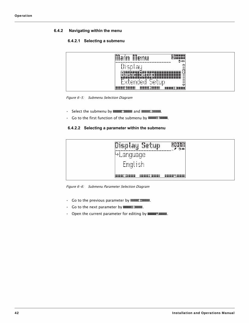
6.4.2 Navigating within the menu
6.4.2.1 Selecting a submenu
Figure 6-5: Submenu Selection Diagram
• Select the submenu by and .• Go to the first function of the submenu by .
6.4.2.2 Selecting a parameter within the submenu
Figure 6-6: Submenu Parameter Selection Diagram
• Go to the previous parameter by .• Go to the next parameter by .• Open the current parameter for editing by .

Tank Side Monitor
Varec, Inc. 43
6.4.3 Editing parameters
6.4.3.1 Parameters with selection list
Figure 6-7: Parameter Selection List Diagram
• Select the parameter value by and .• Mark the selected value by .• Confirm the marked value by .
6.4.3.2 Reference parameters
Figure 6-8: Reference Parameters Diagram
Reference parameters describe where a numerical or logical value (here: Primary Value) is obtained from. The selection consists of two steps:
1. Select the function group, from which the value is to be obtained (here: Tank Value).2. Select the value within this group (here: Corrected Level).
There is a separate selection list for each of these steps.

Operation
44 Installation and Operations Manual
6.4.3.3 Alphanumeric parameters
Figure 6-9: Alphanumeric Parameters Diagram
• Set the activated digit by and .• Go to the next digit by .• If appears at the active digit, the currently displayed value can be accepted by .• If ¬ appears at the active digit, return to the previous digit by .
6.4.4 Quitting the menu
Return to the measured value display by pressing all keys simultaneously.
6.5 Locking/Unlocking Parameters
6.5.1 Software locking
If the instrument is in the measured value display, it can be locked by pressing all keys simultaneously.
In doing so, “Access Code” is set to “0” (i.e. parameters can no longer be changed) and “Service English” is set to “off” (i.e. the display is returned in the language selected by the customer).
6.5.2 Software unlocking
If you try to edit a parameter, the device goes to the “Access Code” function. Enter “100”. Parameters can be changed again.

Tank Side Monitor
Varec, Inc. 45
6.5.3 W&M hardware locking switch
A hardware locking switch for W&M sealing is located behind the display module. All W&M parameters can be set to definite values and locked by this switch. In this state, the 4590 TSM can be used for W&M applications.
In order to operate the hardware locking switch, proceed as follows:
Figure 6-10: W&M Hardware Locking Switch Diagram
Warning! Danger of electrical shock! Before opening the housing, completely switch off the power supply.
1. Using a 3 mm (7/64”) Allen wrench, loosen the safety pin for the display lid.2. Unscrew the display lid.
Note If the display lid is difficult to unscrew, unplug one of the cables from the cable gland to allow air to enter the housing. Then, attempt once again to unscrew the display lid.
3. Turn the display module sideways.4. Place the locking shift into the desired position:

Operation
46 Installation and Operations Manual
• :W&M parameters are free.
• :W&M parameters are locked.5. Replace the display lid on the 4590 TSM housing.
Note Make sure to clean threads on lid to remove any dust or particles. Check that the O-ring is in place and reapply anti-seize-grease.
6. Adjust the safety pin so that it is set over the display lid and tighten. The safety pin can now be secured by a sealing thread and a sealing ring.
6.5.4 Sealing of the 4590 TSM
When the tests according to the applicable regulatory standards have been completed, it is required to secure the housing cover with a sealing wire and a sealing ring.
Figure 6-11: Sealing of the 4590 TSM Diagram

Tank Side Monitor
Varec, Inc. 47
7 Commissioning
7.1 Theoretical Background
7.1.1 Function blocks and data flow
The internal architecture of the 4590 TSM is organized as function blocks. During commissioning one can link the outputs and inputs of different function blocks in order to define a data flow through the 4590 TSM.
Generally one can distinguish three parts of the data flow:
1. Data entered into the 4590 TSM via the input blocks. There is a block for each connected HART device (for example: FMR, NMT, PMD). Depending on the instrument version, there are additional Analog (AI) and Digital (DI) Input blocks.
2. Data are processed in the TANK function block (tank calculations and corrections) and in the Alarm (AL) function blocks.
3. Data are output to• the display• the fieldbus via the fieldbus function blocks (for example: MODBUS, ENRAF,...)• the analog or digital outputs via the Analog (AO) and Digital (DO) output blocks.
7.1.2 Linking sensors to function blocks
To commission the 4590 TSM, it is necessary to connect all Tank HART sensor blocks to one of the internal function blocks, either the “tank functions” block or the “alarm function” block. The outputs of these function blocks can then be mapped to the display, the fieldbus function block and the AO or DO blocks.
By default, these mappings are set to the most common default values. Some of these default mappings are unbreakable system links, others can be modified by the user.
The linking is performed by reference parameters (marked by the ending “REF” in the parameter name). For each of these reference parameters the desired source can be selected from a list.
7.1.3 Linking digital inputs
An additional Digital Input can either be linked to the field protocol inputs or directly to a Digital output. This latter case is usually used for overspill protection.

Commissioning
48 Installation and Operations Manual
7.1.4 Example of block linking
Figure 7-1: Example of Block Linking Diagram
The level value as given by the FMR level radar via the HART protocol is read into the FMR function block. The FMR function block sends the value to the TANK function block, to be stored in the “Level Ref” data point. From here, it is displayed in the primary display as well as communicated to the Modbus protocol function block, which maps the value to the adequate Modbus register.
MODBUS
Temperature
Vapour Temp
Air Temp
Water Level
P1 (Bottom)
P2 (Middle)
P3 (Top)
Obs. Density
Lvl. Flow Rate
Vol. Flow Rate
GP 1 Value
GP 2 Value
GP 3 Value
GP 4 Value
Element 1..16
Value #1..8 Ref
4..20m A Ref
Discrete #1..8 Ref
Meas. Level
Level %
Level
Value #1..4
Discrete #1..4
TANK
Level %
Level
Temp Ref
Vapour Ref
Air Temp Ref
Water Level Ref
P1 (Bot) Ref
P2 (Mid) Ref
P3 (Top) Ref
GP 1 Ref
GP 2 Ref
GP 3 Ref
GP 4 Ref
Element 1..16 Ref
Level Ref
Meas. Level
Temperature
Vapour Temp
Air Temp
Water Level
P1 (Bottom)
P2 (Middle)
P3 (Top)
Obs. Density
Lvl. Flow Rate
Vol. Flow Rate
GP 1 Value
GP 2 Value
GP 3 Value
GP 4 Value
Element 1..16
Tank Ref. Height
DISPLAYPrimary Value
Sec. Value 1
Sec. Value 2
Sec. Value 3
Sec. Value 4
DO #AValueRef
DO #BValueRef
I.S. DI #1Input
Value
I.S. AIValue
Input Value
Input Value %
FMR 54xFMR 53xFMR 23x
Meas. Level
PV Value
Meas. Distance
HAR TBu s
NMT 539+W B
Liquid Temp
Level Source
Vapour Temp
Water Level
Element 1..16
AL-L
HH Alarm
HH+ H A larm
ValueRef
H A larm
Any Alarm
L A larm
LL Alarm
L+LL Alarm
I.S. DI #2Input
Value

Tank Side Monitor
Varec, Inc. 49
In parallel, the level value is sent to the NMT function block, from where it is sent to the NMT Prothermo/N453x in order to assign the product level for the product temperature respectively the product vapor temperature.
Additionally, a digital input value is directly transferred from the Digital Input block (I.S. DI#1) to a Digital Output block (DO#B) as well as an analog value from the Analog Input Block (I.S. AI) to the MODBUS Block.
Furthermore, the level is evaluated in the Alarm block (AL-L). If the HH limit is overshot, an alarm signal will be transmitted via the Digital Output Block (DO #A).
7.1.5 Validating weight & measure approved measurements
The weight & measure status is evaluated by the 4590 TSM on two stages:
• On a first stage, the measurement device value coming into the 4590 TSM is evaluated.• On a second stage, the TANK function block is evaluated.
7.1.5.1 Status of a measurement device
The weight & measure status of a measurement device is o.k. if:
• the custody transfer switch (or the related software setting) of the device is closed• no alarm status is received from the measurement device• for the 7500 Series Radar Tank Gauges level radar: the custody transfer status is “active
positive”• for a RTD transmitter: the sensor’s custody transfer switch is locked, the sensor position is
defined and situated between the defined min. and max. alarm values.
If any of these conditions are not met, then the instruments measured values will be shown with the “#” symbol in the HART device menu.
7.1.5.2 Status of the TANK function block
The weight & measure status of the TANK function block is o.k. if:
• the custody transfer switch of the 4590 TSM is closed• the referenced measured value has a validated weight & measure status• additionally for the level measurement: no tank calculations (CTSh, HyTD, HTMS, HTG) are
activated
If any of these conditions are not met, then the “#” symbol is displayed along with the displayed tank function group value in the display.
The tank values are transmitted via the field protocol to the control room along with the current weight & measure status.

Commissioning
50 Installation and Operations Manual
7.2 Configuring the HART Interface
The 4590 TSM comes with two HART interfaces; the Ex i interface and the Ex d interface.
• On the Ex i side, the 4590 TSM is always operating as HART Master polling the instruments connected. It can also temporarily operate as HART Slave in order to communicate with FieldCare.
• On the Ex d side, the HART interfaced is controlled by the “Analog IO/AO” function group. The following modes can be selected:
• Enabled In this mode no HART signal is used on the Ex d side. There is only a 4-20 mA signal present at the analog output.
• HART Slave In this mode data can be transmitted from the analog output to a primary or secondary HART Master (for example: FieldCare).
• HART MasterIn this mode the 4590 TSM can poll HART instruments which are connected to the Ex d HART bus.
The following sections describe these modes in more detail.
7.2.1 Ex i interface only (default mode)
This mode becomes effective if the Analog Output is set to “Enabled”.
Figure 7-2: Ex i Interface Only (Default Mode) Diagram
In this mode the HART Master scans the measuring devices on the Ex i bus to obtain the measured values.
The HART Slave is normally inactive, used to communicate with FieldCare when connected to the Ex i bus. The HART Slave address of the 4590 TSM is controlled by the parameter “NRF Output/HART Slave/Slave Setup/Comm. address”(9121). By default this address is set to “15”.
On the Ex d side, no HART signal is available. Only the 4-20 mA current signal can be used.1) The Ex d HART bus is not available on a Modbus 4590 TSM with order code *4*********(without 4...20 Input or Output).
4590 TSM
E x i bus 4..2 0 mA
MS
= HART Master= HAR lave
AO=Enabled
M S
#1 #2
#15
Ex i E x d
ST

Tank Side Monitor
Varec, Inc. 51
7.2.2 Ex i interface with Ex d Slave interface
This mode becomes effective if the Analog Output is set to “HART Slave”.
Figure 7-3: Ex i Interface with Ex d Slave Interface Diagram
In this mode the HART Master scans the measuring devices on the Ex I bus to obtain the measured values.
The HART Slave on the Ex I bus is normally inactive, used to communicate with FieldCare when connected to the Ex I bus. The HART Slave address of the Ex i interface of the 4590 TSM is controlled by the parameter “NRF Output/HART Slave/Slave Setup/Comm. address”(9121). By default this address is set to “15”.
The HART Slave on the Ex d bus provides data to an external Primary or Secondary master. The HART Slave address of the Ex d interface of the 4590 TSM is controlled by the parameter “Analog IO/AO/HART Slave/Comm. Address”(7341). By default this address is set to “0”, which means that the HART signal and a 4-20 mA signal are output.
The HART slave values are the same for both HART Slaves (except for the HART address). They can be configured through the “NRF Output/HART Slave/Slave Values” menu.
AO
AO#0#15
#1..15#15
#1 #2
4590 TSMEx i
HART + 4..20 mA
Ex d
M S*
M S*
S#
S#
S = HART SlaveM = HART Master
A0 = HART Slave
A0 = HART Slave
#1
Exi bus
Exi bus Exi bus
#2
4590 TSM

Commissioning
52 Installation and Operations Manual
7.2.3 Ex i interface with Ex d interface in multidrop mode
If addresses from “1” to “15” are selected on the Ex d bus, the HART signal is superimposed over a fixed current and the instruments can be used in multidrop mode:
Figure 7-4: Ex i Interface with Ex d Interface in Multidrop Mode Diagram
4590 TSMEx d busEx i
Ex i bus
#1 #2
A0 #1
#15 #1
#15 #2
#15 #3
A0 #2
A0 #3
#1 #2
#1 #2
Ex i bus
Ex i bus
4590 TSM
4590 TSM
A0 = HART Slave
A0 = HART Slave
A0 = HART Slave
M = HART MasterS = HART Slave
M S* S#
M S* S#
M S* S#

Tank Side Monitor
Varec, Inc. 53
7.2.4 Ex i interface with Ex d Master interface
This mode becomes effective if the Analog Output is set to “HART Master”.
Figure 7-5: Ex i Interface with Ex d Master Interface Diagram
In this mode the HART Master scans the measuring devices on both the Ex I & Ex d buses to obtain the measured values.
The HART Slave is normally inactive, used to communicate with FieldCare when connected to either the Ex I or Ex d bus.
There is only one HART Slave address, which is valid for both the Ex d and the Ex i interface. It is controlled by the parameter “NRF Output/HART Slave/Slave Setup/Comm. address”(9121). By default this address is set to “15”.
In this mode all HART devices no matter where they are connected must have unique HART polling addresses.
M S*
4590 TSMEx i Ex d
Ex i bus Ex d busA0
#15
#1 #2 #3
A0 = HART Master
M = HART MasterS = HART Slave

Commissioning
54 Installation and Operations Manual
7.3 Addressing of the HART Instruments
If possible, the addresses of the HART instruments should be set before connection to the 4590 TSM.
The default block configurations require usage of the following addresses:
1) The types of tank calculations are described in the “Appendix” on page 93.2) If the RTD interface of the 4590 TSM is used for spot temperature measurement, no HART
temperature sensor is required. In this case address “2” should remain unassigned.
Caution! Do not connect a device with address “0”! Such a device has an active 4... 20 mA output which may overload the HART bus, disrupting all HART communication.
Note The HART interface on the non-I.S. side of the 4590 TSM can be operated in different modes. If the “slave” mode has been selected, the HART loops on the I.S. and the non-I.S. sides will operate independently of each other. Therefore, it would be pos-sible to use devices with the same HART address on the I.S. and on the non-I.S. loop. In order to prevent confusion, we strongly recommend avoiding this kind of double usage of addresses.
Tank calculation1) Addresses of the individual HART devices
Level Temperature2) Pressure 1 (bottom)
Pressure 2 (middle)
Pressure 3 (top)
level only 1 - - - -
level + temp. 1 2 - - -
HTMS + P1 1 2 3 - -
HTMS + P1,3 1 2 3 - 5
HTG P1 - 2 3 - -
HTG P1,3 - 2 3 - 5
HTG P1,2 - 2 3 4 -
HTG P1,2,3 - 2 3 4 5
Table 7-1: Default Block Configurations Addresses

Tank Side Monitor
Varec, Inc. 55
7.4 Steps of the Commissioning Procedure
1. Automatic check of the HART addresses of the connected devices2)
After connection of the HART devices, the 4590 TSM will check if all HART addresses are unique and not equal to “0”. If this is not the case, then an alarm message will be displayed. In parallel, the actual HART addresses of the connected gauges can be checked in the “HART devices”(8- - -) function group.
2. Define the display values of the 4590 TSM
In the “Display”(2- - -) function group, the information to be displayed and their format (such as language, timing, scroll rate) is defined.
a. Primary ValueThe primary value will be continuously displayed in the upper part of the main display screen.
b. Secondary ValuesUp to four secondary values will be displayed, which will be displayed cyclically in the lower part of the main display screen.
3. Select the display units
The following unit presets are selectable in the “units preset”(2031) function:
Note Only Tank values will be displayed in 4590 TSM units, values directly from HART devices will be displayed in the HART devices units.
4. Configure the connected HART devicesAfter connecting all HART devices to the HART multidrop line of the 4590 TSM, these gauges can be configured via the 4590 TSM display. In the “HART devices”(8- - -) function group, all connected devices are displayed with their respective HART address in brackets (for example: FMR53x[01]).
a. Devices known to the 4590 TSMVarec devices “known” to the 4590 TSM will be represented by their product code, for example: “FMR53x” for 7500 Series Radar Tank Gauges, “NMS” for 6005 STG, “NMTxxx” for the N453x ATC, and so on. If more than one device of a specific type is connected, each individual device will be represented in the 4590 TSM by a separate function block.
2) In the Software Version SW 02.01, the HART buses on the I.S. and on the non-I.S. side arecontinuously monitored by the 4590 TSM. This means, that in contrast to SW 01.xx, an initialHART scanning of the bus does not need to be performed. As soon as a new HART device isfound, it is displayed with its HART communication address in the “HART Devices” (8- - -) group.
Selection Level Pressure Temperature Density Level Flow Volume Volume Flow
mm, bar, °C mm bar °C kg/m3) m/h m3) m3/h
m, bar, °C m bar °C kg/m3 m/h m3) m3/h
mm, PSI, °C mm PSI °C kg/m3 m/h m3 m3/h
ft, PSI, °F ft PSI °F °API ft/h us gal us gal/h
ft-in-16, PSI, °F ft-in-16 PSI °F °API ft/h us gal us gal/h
ft-in-8, PSI, °F ft-in-16 PSI °F °API ft/h us gal us gal/h
Table 7-2: Selectable Unit Presets

Commissioning
56 Installation and Operations Manual
b. Devices not known to the 4590 TSMDevices not known to the 4590 TSM will be presented as “generic HART device”. For these, the universal HART commands and variables (such as communication address, TAG, message, PV, SV, and so on) are supported.
5. Link the gauges to the tank functionsa. Level and temperature functions
In the “Basic Configuration”(32- -) function group, the connected HART devices are linked to the Tank functions simply by choosing the appropriate references.
For instance, a 7500 Series Radar Tank Gauges FMR53x level gauge will appear as a selectable choice in the “level reference”(3201) function, and by checking the box, the PV of this gauge will be taken by the 4590 TSM as the measured level.
In the same manner, a connected N453x ATC average temperature transmitter can be chosen as “temperature reference”(3202) by checking its product code in the selection list.
b. Other typical Tank Gauging functionsFor other typical Tank Gauging sensors, the appropriate links are found in either the “Extended Configuration”(33- -) or the “Pressure Setup”(34- -) function groups.
c. General Purpose FunctionsDevices which offer functionality not provided for in the standard function groups (for example pH meters) can be connected to the “General Purpose”(35- -) functions. Here, the user can define a function name for the indication on the 4590 TSM display. The units of the device will not be processed in the tank function group. Instead, the values are transmitted directly to the output field protocols.
6. Define the tank calculations and the tank correctionsIn case any typical tank calculations (as the hydrostatic level measurement or the hybrid tank measurement) or tank corrections (as the “hydrostatic tank shell compensation” or the “correction of the thermal expansion”) shall be performed, these functions can be easily set up in the “Calculations”(36- -) function group.
If any level corrections are defined in the calculation functions, then the corrected level is automatically sent to the HOST system via the field protocol.
Further Information can be found in the Description of Instrument Functions Manual.
7. Define alarm functionsa. Alarm type and limits
For all input variables, alarm limits can be defined. In the “Alarm”(5- - -) function group, the alarm type (level, temperature, various) and the alarm behavior can be selected.
b. Alarm behaviorTo have the alarm disappear when the value is back in normal state, the “enabled” selection has to be made. To wait for alarm acknowledgement, the “latching” selection is appropriate. In both cases, the alarm limits have to be defined in the following steps. Either one or all values may be defined.
c. Extended alarm setupIn the extended alarm setup, additional default values (such as damping factor, hysteresis, and so on) may be changed.
3) For a list of values which can be transmitted by the individual protocols, refer to Chapter 11"Technical Data" on page 81.

Tank Side Monitor
Varec, Inc. 57
8. Define discrete inputs and outputs
In the “Discrete I/O”(6- - -) function group, both, the I.S. in- and outputs as well as the explosion proof (non-I.S.) in- and outputs may be configured.
9. Configure the field protocolFor each protocol listed below these parameters should be configured. Additional parameters may in some cases require changes from the default values. A description of these parameters can be found in the Description of Instrument Function Manual (SRM006) and the protocol specific document.
Sakura V1 (SRM012)• “Type”(9211)
defines the primary V1 communication type to be compatible with your control room system.
• “Id”(9212)
must be set to a unique number on this V1 loop.
EIA-485 Modbus (SRM007)• “Id”(9211)
must be set to a unique number on this Modbus loop.• “Baud Rate”(9212) and “Type”(9213)
must be the same as the control room system setting.
• Floating Values• “FP Mode”(9214)
must match the control room system floating point type.• “V01 Map. Mode”(9223)
must be set to “Float Vals” if access to software V01 compatible register map is required.
• “Word Type”(9221)
must be configured to match the control room integer type.
• Integer Values• “Word Type”(9221)
must be configured to match the control room integer type.• “V01 Map. Mode”(9223)
must be set to “Integer Vals.” if access to software V01 compatible register map is required.
• “0% Value” and “100% Value” (in the “Integer Scaling” menu) must be configured to obtain correct integer values (see Section 7.5, "Configuring the Modbus Integer Scaling" on page 59).
Whessoematic WM550 (SRM011)• “Id”(9211)
must be set to a unique number on both of the WM550 loops.• “Baud Rate”(9212)
must match the control room equipment settings.• “Software Id”(9213)
may need to be changed for some control room systems to enable the required functionality.
• If the second loop has a different baud rate, the “Loop 2"(9231) parameter must be set to “Different” and the “Baud Rate (2)”(9232) can be configured.
BPM (SRM014)• “Id length”(9211) and “Baud Rate”(9213)
must be configured to match the control room settings.• “Id”(9212)
must be set to a unique number on the BPM loop.
Commissioning
58 Installation and Operations Manual
• “TOI”(9214), “Device No [dn]”(9215) and “Dev. Type [dt]”(9216)
must be configured to achieve the correct Enraf gauge emulation.
Mark/Space (SRM009)• “Id”(9211)
must be set to a unique number on both of the Mark/Space loops.• “Baud Rate”(9212), “Type”(9213), and “Data Mode”(9214)
must match the control room equipment settings.
GPE (SRM013)• “Id”(9211)
must be set to a unique number on both of the Mark/Space loops.• “Baud Rate”(9212), “Type”(9213), and “Loop Mode”(9214)
must match the control room equipment settings.

Tank Side Monitor
Varec, Inc. 59
7.5 Configuring the Modbus Integer Scaling
Note This chapter applies only to the Modbus version of the 4590 TSM.
In order for the 4590 TSM to send correct integer values to the control room, the scaling factors must be configured; these are used to convert the floating-point measured/calculated values into suitable integer values.
7.5.1 Integer scaling
Scaling of a value is handled by a pair of parameters (“0% Value” and “100% Value”). Each type of measured value (Level, Temperature, Density, Pressure, and so on.) has its own set of scaling parameters due to the different value ranges each data type uses.
In most cases 0% will have a value 0; here the integer value is simply calculated as follows:
Integer = “Maximum Integer Value” Value“100% Value”
In the cases where 0% is not 0, the integer value is calculated as follows:
Integer = “Maximum Integer Value” (Value - "0% Value"(“100% Value” - “0% Value)”
Where “Maximum Integer Value” is• for unsigned integers: 65535• for signed integers: 32767
Figure 7-6: Scaling of a Value Diagram
0% 100%
0
65535
100%
32767
-100%
-32767measured
value
integer
value
measured
value
integer
value
Unsigned Integer Signed Integer

Commissioning
60 Installation and Operations Manual
7.5.2 Examples of integer scaling for maximum accuracy
For maximum accuracy of the integer value, simply set the “100% Value” to the maximum possible value you require, this maximum value will then be transmitted to the control room as the integer value 65535 (for unsigned values) and 32767 (for signed values). The control room system must then scale the value back into the original value using the same scaling factors.
Example 1
• Level = 23665 mm• 0% Value = 0 mm• 100% Value = 35000 mm (Maximum level value)
--> Unsigned Integer value = (65535 / 35000) × level = 44351
Example 2
• Level = 7.886 ft.• 0% Value = 0 ft.• 100% Value = 32.000 ft. (Maximum level value)
--> Signed Integer value = (32767 / 32) × level = +8075
7.5.3 Examples of integer scaling for human readable values
To obtain an integer value which is immediately accessible to the operator it is advisable to scale the measured value by a power of 10 (such as 1, 10, 100, 1000,...).
For example the level “23.45 ft.” might be represented by the integer “23450” (factor 1000).
In order to obtain this type of values, the scaling factors must be calculated as follows:
• 0% value = 0• 100% value =
• for unsigned integers: 65535 divided by a suitable factor of 10.• for signed integers: 32767 divided by a suitable factor of 10.

Tank Side Monitor
Varec, Inc. 61
This yields the following common configuration values, which can be directly used for most applications:
1) The 0% and 100% values are always specified in the current 4590 TSM units.2) This value is a result of rounding of fractional values.
Example 1
• Level = 23655 mm• 0% value = 0 mm• 100% value = 65535 mm (according to the table above)
--> Unsigned integer value = 23655
Example 2
• Level = 7.886 ft.• 0% value = 0 ft.• 100% value = 32.767 ft. (according to the table above)
--> Signed integer value = +7886
Example 3
• Level = 14’ 8” 3/16 (= 14.682 ft.)• 0% value = 0’ 0” 0/16• 100% value = 65’ 6” 7/16 (according to the table above)
--> Unsigned integer value = 14682
Requirement 100% value forunsigned integers1)
100% value forsigned integers1)Measured value Integer value
12.345 12 65535.000 32767.000
123 6553.500 3276.700
12352) 655.350 327.670
12345 65.535 32.767
12’ 10” 3/8(12.615 ft.)
1261565’ 6” 3/8
(65.535 ft.)32’ 9” 2/8
23’ 10” 7/16(23.870 ft.)
2387065’ 6” 7/16(65.535 ft.)
32’ 9” 3/16(32.767 ft.)
Table 7-3: Common Configuration Values

Commissioning
62 Installation and Operations Manual

Tank Side Monitor
Varec, Inc. 63
8 Maintenance and Repairs
8.1 Exterior Cleaning
When cleaning the exterior, always use cleaning agents that do not attack the surface of the housing and the seals.
8.2 Replacing Seals
The seals of the sensors must be replaced periodically, particularly if molded seals (aseptic construction) are used. The period between changes depends on the frequency of cleaning and on the temperature of the measured substance and the cleaning temperature.
8.3 Repairs
The Varec repair concept assumes that the measuring devices have a modular design and that customers are able to undertake repairs themselves.
Spare parts are contained in suitable kits. They contain the related replacement instructions.
All the spare parts kits, which you can order from Varec for repairs are listed with their order numbers in Section 8.5, "Spare Parts" on page 64.
For more information on service and spare parts, contact the Service Department at Varec.
8.4 Repairs to Ex-Approved Devices
When carrying out repairs to Ex-approved devices, please note the following:
• Repairs to Ex-approved devices may only be carried out by trained personnel or by Varec Service.
• Comply with the prevailing standards, national Ex-area regulations, safety instructions, and certificates.
• Only use original spare parts from Varec, Inc.• When ordering a spare part, please note the device designation on the nameplate. Only
replace parts with identical parts.• Carry out repairs according to the instructions. On completion of repairs, carry out the
specified routine test on the device.• Only Varec Service may convert a certified device into a different certified variant.• Document all repair work and conversions.

Maintenance and Repairs
64 Installation and Operations Manual
8.5 Spare Parts
8.5.1 Overview
Figure 8-1: Spare Parts Diagram
Modification Nameplate:
52018674
5202363152023630
55 26418 55
Isolation plate
Isolation plate
I.S. main board
I.S.
Isolation plates
Cover for electronics screws,holding devices , and I/O module fixing bracket
Display cover
Power supply
Plugs
Power supplyPower supply
Four sealing plugsFour sealing plugsFour sealing plugsand two O-ring sealsTwo sealing plugsand two O-ring seals
Sealing kit, O-ring set
Two cable glands
G 1/2
M20X1.5
(See the service manual for details).
and O-ring seal
Display
Exd terminal board, cover,
Exi terminal boardcover, screws andwashers
screws and washers

Tank Side Monitor
Varec, Inc. 65
8.5.2 PC board 4590 TSM
Consists of an I.S. board and a communication board. These boards are adapted to each other and both always have to be changed.
10 CertificatesA For non-hazardous areasS FM XP-Class I, Division 1, Group A-DU CSA XP-Class I, Division 1, Group A-D6 ATEX II 2 (1) G EEx d (ia) IIC T4Y Special version, to be specified
20 Field communication protocolE ENRAF BPM, non-I.S. 4-20mA input, non-I.S. 4-20mA HART Master outputG GPE, non-I.S. 4-20mA HART Master output1 WM550, non-I.S. 4-20mA output, Whessoe protocol with dual communication3 Varec Mark/Space, non-I.S. 4-20mA input, non-I.S. 4-20mA HART Master output5 Modbus, non-I.S. 4-20mA input, non I.S. 4-20mA HART Master output, EIA 4857 L&J, non-I.S. 4-20mA input, non-I.S. 4-20mA HART Master output8 V1, non-I.S. 4-20mA output, non-I.S. 4-20mA HART Master output, relay output9 Special version, to be specified
30 Spot RTD option0 Without RTD temperature input1 With spot RTD temperature input, I.S.9 Special version, to be specified
40 Custody Transfer ApplicationsN Custody transfer approval not selectedY Special version, to be specified
ORF590x Complete product designation

Maintenance and Repairs
66 Installation and Operations Manual
8.6 Return
The following procedures must be carried out before a transmitter is sent to Varec for example, for repair or calibration:
• Remove all residue which may be present. Pay special attention to the gasket grooves and crevices where fluid may be present. This is especially important if the fluid is dangerous to health, for example: corrosive, poisonous, carcinogenic, radioactive, and so on.
• Always enclose a duly completed “Declaration of contamination” form (a copy of the “Declaration of contamination” is included at the end of this operating manual). Only then can Varec transport, examine and repair a returned device.
• Enclose special handling instructions if necessary, for example a safety data sheet as per EN 91/155/EEC.
Additionally specify:
• An exact description of the application.• The chemical and physical characteristics of the product.• A short description of the error that occurred (specify error code if possible).• Operating time of the device.
8.7 Disposal
In case of disposal, please separate the different components according to their material consistence.

Tank Side Monitor
Varec, Inc. 67
8.8 Software History
1) The software version of the instrument is displayed immediately after switch-on of the supplyvoltage.
Software version1) Changes to software Associated documentation
V 01.00V 01.01V 01.02
• BA 039G (Operating Instructions)• BA 042G (Description of Instrument
Functions
V 01.03 can be operated via ToF Tool V3.0/3.1 • BA 256F/00/ae/02.02 (Operating Instructions)
• BA 257F/00/ae/02.02 (Description of Instrument Functions)
V 01.04 can be operated via ToF Tool V3.0/3.1(additional Device Descriptions required)
• BA 256F/00/en/09.02 (Operating Instructions)
• BA 257F/00/en/09.02 (Description of Instrument Functions)
V 01.04.06 GPE and V1 protocol introduced; can be operated via ToF Tool V 3.0/3.1(additional Device Descriptions available)
• IOM029FVAE1103 (Operating Instructions)
• BA 257F/00/en/03.03 (Description of Instrument Functions)
V 02.01.xx Operating concept completely revised;Enraf protocol introduced;
• BA 256F/00/en/12.04 (Operating Instructions
V 02.02.xx Priorisation of level update rate • IOM029FVAE0306 (Operating Instructions)
• SRM006FVAE0306 (Description of Instrument Functions)
V 02.03.xx • user calibration of AO, AO#2, AI, IS AI and IS RTD
• Status system with error codes• value entering in ft-in-16 and ft-in-8
• BA256F/00/en/07.06 (Operating Instructions
• BA257F/00/en/07.06 (Description of Instrument Functions)
V02.04.xx • Integration of Proservo NMS5• Support of remote configuration via
MODBUS and V1• Enhancement of functionality of the
optical keys
• IOM029FVAE0510 (Operating Instructions)
• SRM006FVAE0510 (Description of Instrument Functions)

Maintenance and Repairs
68 Installation and Operations Manual

Tank Side Monitor
Varec, Inc. 69
9 Accessories
9.1 Discrete I/O Modules
9.1.1 Standard mechanical diagram for all I/O modules
Figure 9-1: Standard Mechanical Diagram for all I/O Modules
1.00(25.4)
.25(6.35)
.040 (1.0) DIA.
.30(7.6)
.200(5.1)
.700(17.8)
1.100(27.9)
1.30(43.1)
.100(2.5)
.40(10.2)
123+5
1.70(43.1)
4
1.70(43.1)
1.00(25.4)
(5 PLACES)
BOTTOM VI EW

Accessories
70 Installation and Operations Manual
9.1.2 Output modules
1) This order code is valid if the module is pre-installed in the 4590 TSM as module A or moduleB.
2) This order is valid if the module is ordered as an accessory.3) This upper limit of the load current is determined by the 4590 TSM.
AC voltage DC voltage
4590 TSM order code1) module A
4590 TSM - ****J******
4590 TSM - ****G******
4590 TSM - ****H******
4590 TSM - ****K******
4590 TSM order code1)
module B
4590 TSM - *****J*****
4590 TSM - *****G*****
4590 TSM - *****H*****
4590 TSM - *****K*****
Order Code2) 52012959 52012960 52012961 52012962
Color of housing black black red red
Load voltage 24 ... 140 V AC 24 ... 250 V AC 3 ... 60 V DC 4 ... 200 V DC
Load current 30 ... 500 mA eff. 20 ... 500 mA eff.1
Typ. power dissipation
1 W/A 1 ... 1.5 W/A
Transient protection Meets IEEE472 Meets IEEE472
Type of contact SPST normally open Zero crossing turn-on
SPST normally open
Optical isolation yes yes
Isolation voltage 4000 V eff. 4000 V eff.
Approvals UL, CSA, CE, TÜV UL, CSA, CE, TÜV
Table 9-1: Output Modules
1
2
3
4
+
-VAC/DC
Logic
Amplifier
1
2
3
4
+
-
VAC
Logic
ZeroVoltageCircuit
AC DC

Tank Side Monitor
Varec, Inc. 71
9.1.3 Input modules
1) This order code is valid if the module is pre-installed in the 4590 TSM as module A or moduleB.
2) This order is valid if the module is ordered as an accessory.3) This upper limit of the load current is determined by the 4590 TSM.
AC voltage DC voltage
4590 TSM order code1)
module A4590 TSM -****B******
4590 TSM -****D******
4590 TSM -****C******
4590 TSM -****E******
4590 TSM order code1)
module B4590 TSM -*****B*****
4590 TSM -*****D*****
4590 TSM -*****C*****
4590 TSM -*****E*****
Order code2) 52012955 52012956 52012957 52012958
Color of housing yellow yellow white white
Input voltage 90 ... 140 V AC 180 ... 264 V AC3) 3 ... 32 V DC 35 ... 60 V DC
Nominal input resistance 22 kW 60 kΩ 22 kΩ 60 kΩ
Max. pick-up voltage 90 V AC 180 V AC 3 V DC 35 V DC
Min. drop-out voltage 25 V AC 50 VAC 1 V DC 9 V DC
Input current @ max. voltage
8 mA rms 8 mA rms
Typ. power dissipation 1 ... 1.5 W/A 1 ... 1.5 W/A
Transient protection Meets IEEE472 Meets IEEE472
Optical isolation yes yes
Isolation voltage 4000 V rms 4000 V rms
Approvals UL, CSA, CE, TÜV UL, CSA, CE, TÜV
Table 9-2: Input Modules
AC DC
1
2
3
4
5
+
–VDC
Logic
OutSchmittTrigger
Ground
1
2
3
4
5
+
-
VAC/DC
Logic
OutSchmittTrigger
Ground

Accessories
72 Installation and Operations Manual
9.1.4 Relay output module
1) This order code is valid if the module is pre-installed in the 4590 TSM as module A or moduleB.
2) This order is valid if the module is ordered as an accessory.3) For inductive loads, use diode suppression or RC network to improve contact life.4) Including debounce
4590 TSM order code1)
module A4590 TSM - ****R******
4590 TSM order code1)
module B4590 TSM - *****R*****
Order code2) 52026945
Color of housing red
Load voltage 0 ... 100 VDC / 0 ... 120 VAC
Load current 0 ... 500 mA3)
Max. contact resistance 250 mW
Max. turn on/off time4) 1 ms
Min. life expectancy 500000 cycles
Type of contact SPST normally open; mechanical relay
Isolation voltage 1500 Veff
Approvals UL, CSA, CE, TÜV
Table 9-3: Relay Output Module
1
2
3
4
VAC/VDC
AMP
+VCC
INPUT
GROUND5

Tank Side Monitor
Varec, Inc. 73
9.2 Rail Mounting Kit
For rail mounting the 4590 TSM to vertical or horizontal pipe.
Order-Number: 52013134
Figure 9-2: Rail Mounting Kit Diagram

Accessories
74 Installation and Operations Manual
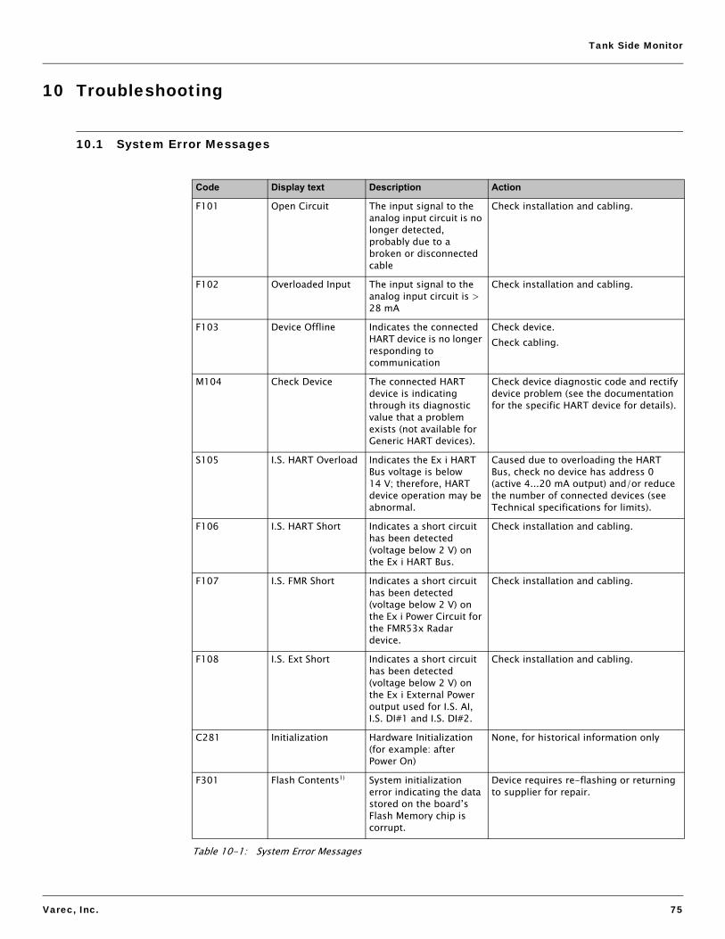
Tank Side Monitor
Varec, Inc. 75
10 Troubleshooting
10.1 System Error Messages
Code Display text Description Action
F101 Open Circuit The input signal to the analog input circuit is no longer detected, probably due to a broken or disconnected cable
Check installation and cabling.
F102 Overloaded Input The input signal to the analog input circuit is > 28 mA
Check installation and cabling.
F103 Device Offline Indicates the connected HART device is no longer responding to communication
Check device.Check cabling.
M104 Check Device The connected HART device is indicating through its diagnostic value that a problem exists (not available for Generic HART devices).
Check device diagnostic code and rectify device problem (see the documentation for the specific HART device for details).
S105 I.S. HART Overload Indicates the Ex i HART Bus voltage is below 14 V; therefore, HART device operation may be abnormal.
Caused due to overloading the HART Bus, check no device has address 0 (active 4...20 mA output) and/or reduce the number of connected devices (see Technical specifications for limits).
F106 I.S. HART Short Indicates a short circuit has been detected (voltage below 2 V) on the Ex i HART Bus.
Check installation and cabling.
F107 I.S. FMR Short Indicates a short circuit has been detected (voltage below 2 V) on the Ex i Power Circuit for the FMR53x Radar device.
Check installation and cabling.
F108 I.S. Ext Short Indicates a short circuit has been detected (voltage below 2 V) on the Ex i External Power output used for I.S. AI, I.S. DI#1 and I.S. DI#2.
Check installation and cabling.
C281 Initialization Hardware Initialization (for example: after Power On)
None, for historical information only
F301 Flash Contents1) System initialization error indicating the data stored on the board’s Flash Memory chip is corrupt.
Device requires re-flashing or returning to supplier for repair.
Table 10-1: System Error Messages

Troubleshooting
76 Installation and Operations Manual
F302 No Order Code System initialization error indicating the factory order code has not been found.
System must be returned to supplier.
F303 App Failure System initialization error indicating the Application Microcontroller is indicating a failure during initialization
If spare parts have been fitted, make sure both boards are from the same set (do not mix old/new boards)If device has been re-flashed, try again.Otherwise, the system must be returned to the supplier.
F304 Com Failure System initialization error indicating the Communication Microcontroller is indicating a failure during initialization.
If device has been re-flashed, try again.Otherwise, the system must be returned to the supplier.
F305 App Error System initialization error indicating the Application Microcontroller is not communicating with the Main Microcontroller in the system.
If spare parts have been fitted, make sure both boards are from the same set (do not mix old/new boards).If device has been re-flashed, try again.Otherwise, the system must be returned to the supplier.
F306 Comm Error System initialization error indicating the Communication Microcontroller is not communicating with the Main Microcontroller in the system.
If device has been re-flashed, try again.Otherwise, the system must be returned to the supplier.
F307 DD Failure System initialization error indicating that a problem occurred when loading one of the device DDs from the Flash Memory.
If device has been re-flashed, try again.Otherwise, the system must be returned to the supplier.
C312 Initialization Hardware initialization (that is, after Internal System Reset)
None, for historical information only.
C401 Factory RESET Indicates the system (or the group) has been reset back to factory settings by the user.
None, for historical information only.
C402 Initialization Configuration Initialization (that is, after Soft Reset from Menu)
None, for historical information only.
S432 Calibration The user and/or factory calibration of this function has failed, and the circuit is currently operating without any calibration.
Re-calibrate using User calibration or Return to supplier for repair.
Code Display text Description Action
Table 10-1: System Error Messages

Tank Side Monitor
Varec, Inc. 77
S434 Scaling The 0% and/or 100% scaling values for the function are invalid, as a result the function cannot operate properly.
Check configuration.
C482 Simulated Output The output function is currently operating in simulation mode; therefore, the output value no longer relates to the process values.
Exit simulation mode.
C483 Simulated Input The input function is currently operating in simulation mode; therefore, the input value no longer relates to the connected process value.
Exit simulation mode.
F501 Value Ref The value reference used as the input value for this function is no longer valid; therefore, the output value is no longer related to the process.
Check configuration.
F502 Device 0 found Indicates that this device has polling address 0. By definition of the HART standard that also means the device has an active 4...20 mA output signal, as this load can vary. Such a device can overload the HART bus and is therefore not allowed by the 4590 TSM system.
Change the device HART address or remove device from system.
F503 Level Ref The Level Reference value is no longer valid (that is, the value it was linked to is no longer available in the system).
Check configuration.
F504 Water Level Ref The Water Level Reference value is no longer valid (that is, the value it was linked to is no longer available in the system).
Check configuration.
F505 Temp. Ref The Temperature Reference value is no longer valid (that is, the value it was linked to is no longer available in the system).
Check configuration.
Code Display text Description Action
Table 10-1: System Error Messages

Troubleshooting
78 Installation and Operations Manual
F506 Vapor Temp. Ref The Vapor Temperature Reference value is no longer valid (that is, the value it was linked to is no longer available in the system).
Check configuration.
F507 Air Temp. Ref The Air Temperature Reference value is no longer valid (that is, the value it was linked to is no longer available in the system).
Check configuration.
F508 P1 Ref The P1 (Bottom) Pressure Reference value is no longer valid (that is, the value it was linked to is no longer available in the system).
Check configuration.
F509 P2 Ref The P2 (Middle) Pressure Reference value is no longer valid (that is, the value it was linked to is no longer available in the system).
Check configuration.
F510 P3 Ref The P3 (Top) Pressure Reference value is no longer valid (that is, the value it was linked to is no longer available in the system).
Check configuration.
C511 CS Restored The user performed a Customer Settings restore operation on the whole system or on this group.
None, for historical information only.
C512 Device Removed The indicated HART device was removed from the system by the user.
None, for historical information only.
C513 Restart The software restart operation was selected by the user.
None, for historical information only.
F514 CS Saved Indicates the user has saved the current configuration of the system as the “Customer Settings”.
None, for historical information only.
C515 User Access The user access code 100 was entered.
None, for historical information only.
C516 Service Access The service engineer access code was entered.
None, for historical information only.
C517 Diag. Access The Varec diagnostic code was entered.
None, for historical information only.
C518 Unknown Access An invalid access code was entered.
None, for historical information only.
Code Display text Description Action
Table 10-1: System Error Messages

Tank Side Monitor
Varec, Inc. 79
C519 Access Locked Indicates the access code was locked, either by changing it to 0 manually or by using the three-button method.
None, for historical information only.
C520 Access Timeout Indicates the access code was removed by the system as the menu had not been used for the timeout period.
None, for historical information only.
S901 Level Held The tank level value is being held at an old value and is no longer being updated (that is, during Dip Freeze).
This may be a normal operation (that is, during Dip Freeze); otherwise, check configuration.
S902 Temp. Held The tank temperature value is being held at an old value and is no longer being updated.
This may be a normal operation; otherwise, check configuration.
S903 Vap. Temp. Held The tank vapor temperature value is being held at an old value and is no longer being updated.
This may be a normal operation; otherwise, check configuration.
S904 Air Temp. Held The tank air temperature value is being held at an old value and is no longer being updated.
This may be a normal operation; otherwise, check configuration.
S905 Water Level Held The Tank water level value is being held at an old value and is no longer being updated.
This may be a normal operation; otherwise, check configuration.
S906 P1 Held The tank P1 (bottom) pressure value is being held at an old value and is no longer being updated.
This may be a normal operation; otherwise, check configuration.
S907 P2 Held The tank P2 (middle) pressure value is being held at an old value and is no longer being updated.
This may be a normal operation; otherwise, check configuration.
S908 P3 Held The tank P3 (top) pressure value is being held at an old value and is no longer being updated.
This may be a normal operation; otherwise, check configuration.
S909 Obs. Density Held The tank observed density value is being held at an old value and is no longer being updated (for example: during HTG mode when level is below pressure sensors).
This may be a normal operation; (that is, when in HTG mode and the level is below the pressure sensors); otherwise, check configuration.
Code Display text Description Action
Table 10-1: System Error Messages

Troubleshooting
80 Installation and Operations Manual
1) Not stored in the Status History.
S910 Flow Held The tank flow rate value is being held at an old value and is no longer being updated.
This may be a normal operation; otherwise, check configuration.
F911 Level Fault The tank level value has failed.
Check configuration, manual values, and references.
F912 Temp. Fault The tank temperature value has failed.
Check configuration, manual values, and references.
F913 Vap. Temp. Fault The tank vapor temperature value has failed.
Check configuration, manual values, and references.
F914 Air Temp. Fault The tank air temperature value has failed.
Check configuration, manual values, and references.
F915 Water Level Fault The tank water level value has failed.
Check configuration, manual values, and references.
F916 P1 Fault The tank P1 (bottom) pressure value has failed.
Check configuration, manual values, and references.
F917 P2 Fault The tank P2 (middle) pressure value has failed.
Check configuration, manual values, and references.
F918 P3 Fault The tank P3 (top) pressure value has failed.
Check configuration, manual values, and references.
F919 Obs. Density Fault The tank observed density value has failed.
Check configuration, manual values, and references.
F920 Flow Fault The tank flow rate value has failed.
Check configuration, manual values, and references.
Code Display text Description Action
Table 10-1: System Error Messages

Tank Side Monitor
Varec, Inc. 81
11 Technical Data
11.1 Overview
11.1.1 Inputs and outputs
Figure 11-1: Inputs and Outputs Diagram
4...20 mA
4...20 mA 4...20 mA
Po wer AC /DC
FMR NMT Pressuretransmitter
V1
Mar k/SpaceL&J
ModbusWM550
Enraf BPM
GP E
Analog In
Analog In(option)
HART (up to 24 mA)
Fieldb us
Discrete In 1 Discrete In 2
Discrete In/Out B(option)
Discrete In/Out A(option)
Spot RTD(option)
Analog Out 2(option)
Discrete Out C(option)
4...20 mA
Analog Out 1with HART
(option)
Non-I.SterminalsEx d.
I.S.terminalsEx ia
Values transmitted by the Field Protocols The following values can be transmitted by the communication protocols:
Tank Value Symbol V1 - old V1 - new Modbus WM550 BPM Mark/Space
L&J Tank-way Basic
L&J Tank-way Servo
GPE
Level L yes yes yes yes yes yes yes yes yes
Temperature (Product) TP yes yes yes yes yes yes yes yes yes
Observed Density Dobs - yes yes yes yes - - yes -
Water Level LW - yes yes yes yes - - yes -
Pressure 1 (Bottom) P1 - yes yes yes1) yes - - - -
Pressure 2 (Middle) P2 - yes yes yes1) - - - - -
Pressure 3 (Top) P3 - yes yes yes yes - - - -
Measured Level LM - - yes yes1) - - - - -
Table 11-1: Values transmitted by the Field Protocols

Technical Data
82 Installation and Operations Manual
1) Only accessible through WM550 extended tasks (51 & 52); not available on older control roomsystems.
2) The protocol allows 2 alarm and 4 general purpose flags that can be connected to any alarmor discrete input.
3) Level L & H alarm, 4 alarms and 2 general purpose flags that can be connected to any alarmor discrete input.
4) The protocol allows 2 digital alarm values that can be connected to any alarm or discreteinput.
5) The protocol allows 2 digital values that can be connected to any alarm or discrete input.
6) One additional value “4-20mA” that can be connected to any value; however range of valuesent is limited (see SRM012 for details).
7) One additional value “Temp2” that can be connected to any value; however, the range ofvalue sent is limited (see SRM010 for details).
Level Correction LC - - yes yes1) - - - - -
Percentage Level L% - - yes yes - - - - -
Vapor Temperature TV - yes yes yes1) yes - - - -
Air Temperature TA - - yes yes1) yes - - - -
Level Flow Rate(Rate of change of level)
- - yes yes1) - - - - -
Volumetric Flow Rate - - yes yes1) - - - - -
General Purpose Value 1 GP1 - yes yes yes1) - - - - -
General Purpose Value 2 GP2 - yes yes yes1) - - - - -
General Purpose Value 3 GP3 - - yes yes1) - - - - -
General Purpose Value 4 GP4 - - yes yes1) - - - - -
Multi-Element Temperatures T(1) to T(16) - yes yes T(1) to T(15)
- - - - -
Alarm/Discrete Values yes2) yes2) yes yes yes3) yes4) yes5) yes5) -
Discrete Output Control - - yes - - - - - 1
Additional - 4-20mA6)
yes Level% - - Temp7) - 4-20mA6)
Protocol Documentation SRM012 SRM012 SRM007 SRM011 SRM014 SRM009 SRM010 SRM010 SRM013
Values transmitted by the Field Protocols The following values can be transmitted by the communication protocols:
Tank Value Symbol V1 - old V1 - new Modbus WM550 BPM Mark/Space
L&J Tank-way Basic
L&J Tank-way Servo
GPE
Table 11-1: Values transmitted by the Field Protocols

Tank Side Monitor
Varec, Inc. 83
11.1.1.1 Non-I.S. inputs and outputs
1) See pos. 20 option 4 of the product structure; Modbus without input or output does notprovide an Ex d HART bus!
11.1.1.2 Technical data of the non-I.S. inputs and outputs
1) The second analog output (available for V1, WM550, and GPE) has no HART option.
2) Start-up current of the HART instruments has to be taken into account.
V1 Modbus WM550 BPM Mark/Space
L&J Tankway
GPE
Analog In AI - option1) - standard standard standard -
Analog Out 1 AO standard+HART
option1)
+HARTstandard+HART
standard+HART
standard+HART
standard+HART
standard+HART
Analog Out 2 AO#2 standard - standard - - - standard
Discrete In/Out A DI#ADO#A
option, s. pos. 50 of the product structure
Discrete In/Out B DI#BDO#B
option, s. pos. 60 of the product structure
Discrete Out C DO#C standard - - - - - -
Table 11-2: Non-I.S. Inputs and Outputs
Analog 4...20 mA Input (option S., Pos. 20 of the product structure)
Item Description
Internal load (to ground) 110 Ω
Measuring range 0 ... 26 mA
Accuracy ±15 µA (after linearization and calibration
Table 11-3: Analog 4...20 mA Input (option, s. pos. 20 of the product structure)
Analog 4...20 mA Output
Item Description
Output current 3 ... 24 mA
Output voltage U = 24 V - ILOAD 400 Ω
Output load max. 500 Ω
Accuracy ±15 µA (after linearization and calibration)
HART options1) • Slave, address # 0: 4... 20 mA active
• Slave, address #1 - #15: fixed current (user selectable)
• Master: max. current (≤ 24 mA) selectable by user; typically 6 HART instruments (each 4 mA) can be connected2)
Table 11-4: Analog 4...20 mA Outputs

Technical Data
84 Installation and Operations Manual
11.1.2 Technical data of the I.S. inputs and outputs
Discrete Inputs/Outputs A and B
The 4590 TSM can be equipped with 1 or 2 discrete I/O modules.
Available types See position 50 and 60 of Product Structure or see Chapter 9 "Accessories" on page 69.
Table 11-5: Discrete Inputs/Outputs A and B
Discrete Output C (for V1 protocol)
Item Description
Load voltage 3 ... 100 V
Load current max. 500 mA
Type of contact mechanical latching relay
Isolation voltage 1500 V
Approvals UL, CSA
Table 11-6: Discrete Output C (for V1 protocol)
I.S. Inputs and Outputs
V1 Modbus WM550 BPM Mark/Space
L&J Tankway
GPE
HART standard standard standard standard standard standard standard
I.S. RTD option, s. pos. 40 of the product structure
I.S. Discrete In 1 I.S. DI#1 standard standard standard standard standard standard standard
I.S. Discrete In 2 I.S. DI#2 standard standard standard standard standard standard standard
I.S. Analog In I.S. AI standard standard standard standard standard standard standard
Table 11-7: I.S. Inputs and Outputs
HART Input Loop
Item Description
Source voltage U = 25 V - ILoad x 333 Ω (typically)
Total Imax Start-up currents of all connected HART devices may not exceed a total of 27 mA
Connectable sensors Depending on current consumption (including start-up current)
Table 11-8: HART Input Loop
Spot RTD Input (Option S., pos. 40 of the product structure)
Item Description
Measuring range 10 ... 600 Ω
Excitation current typ. 400 µA, max. 2000 µA
Table 11-9: Spot RTD Input (option, s. pos. 40 of the product structure)

Tank Side Monitor
Varec, Inc. 85
1) Accuracy of the converter may be influenced by element accuracy.
11.1.3 Auxiliary energy
Type of Sensor Nominal value Tempmin Tempmax Accuracy1)
• Pt100 (385) IEC751
• Pt100 (389)• Pt100 (392)
IPTS-68
100 Ω @ 0 °C (≈ 32 °F) -200 °C (≈ -330 °F) +600 °C (≈ +1110 °F) ±0.1 °C (≈ ± 0.2 °F)
Cu90 (4274) 100 Ω @ 25 °C (≈ 77 °F)[90 Ω @ 0 °C (≈ 32 °F)
-100 °C (≈ -150 °F) +250 °C (≈ +480 °F) ±0.1 °C (≈ ± 0.2 °F)
Ni120 (672) 120 Ω @ 0 °C (≈ 32 °F) -60 °C (≈ -75 °F) +180 °C (≈ +350 °F) ±0.1 °C (≈ ± 0.2 °F)
Ni100 (618) DIN 43760
100 Ω @ 0 °C (≈ 32 °F) -60 °C (≈ -75 °F) +180 °C (≈ +350 °F) ±0.1 °C (≈ ± 0.2 °F)
Table 11-10: Spot RTD — Types of Sensors
I.S. Analog 4...20 mA input (Option S., pos. 70 of the product structure)
Item Description
Source voltage U = 25 V - ILoad x 333 Ω (typically)
Internal load (to ground) 100 Ω
Measuring range 0 ... 26 mA
Accuracy ±15 µA (after linearization and calibration)
Usage Source for Discrete Inputs / Source for 4 ... 20 mA loop device
Table 11-11: S Analog 4...20 mA input (option, s. pos. 70 of the product structure)
Discrete Inputs (option S., pos. 70 of the product structure)
Item Description
Active voltage (“closed circuit”) min. 9 V (default)
In-active voltage (“open circuit”) max. 7 V (default)
Active high current 4 mA
Switching hysteresis 2 V
Table 11-12: Discrete inputs (option, s. pos. 70 of the product structure)
AC supply 55 ... 264 VAC; insensitive to polarity / CSA approved: 55 ... 250 VAC
DC supply 18 ... 55 VAC/DC
Power consumption • 370 mA @ 24 VDC• 200 mA @ 48 VDC• 75 mA @ 125 VAC• 45 mA @ 220 VAC
Fuse Internal (on primary power)
Table 11-13: Auxiliary Energy

Technical Data
86 Installation and Operations Manual
11.1.4 Performance characteristics
11.1.5 Resolution
Resolution of all measured data depends on sensor and communication settings. The following settings are recommended for inventory and custody transfer applications:
For the purpose of consistency, all internal calculations are performed in SI units.
11.1.6 Scan time
11.1.7 Ambient conditions
Accuracy
HART sensors Accuracy of all data from connected HART sensors depends on the type and installation of instruments. The use of the digital HART protocol prevents accuracy data degradation, as would be the case with analogue (4...20 mA) sensors.
Spot RTD input, analog inputs, analog outputs
See Section 11.1.2, "Technical data of the I.S. inputs and outputs" on page 84, for more details.
Table 11-14: Accuracy
Data type Units Inventory control Custody transfer
Level
millimeters 1 mm 1 or 0.1 mm
meters 10 mm 1 or 0.1 mm
feet 0.01 ft. 0.01 ft.
inches 1" or 0.1" 0.01" or 0.001"
ft-in-16 1/16” 1/16”
Temperature°C 0.1 °C 0.1 °C
°F 0.1 °F 0.1 °F
Table 11-15: Resolution
HART sensors The data of connected HART sensors is constantly scanned and updated in the internal data base. The scanning sequence is based on the priorities of the measurements (level - prio 1, temperature - prio 2, pressure - prio 3,...). Typically, a value change on the HART multidrop loop is displayed after a 2 seconds delay (for priority 1 values).
Spot RTD Input RTD resistance is measured and recalculated at least every second.
Table 11-16: Scan Time
Ambient temperature -40 °C ... +60 °C (-40 °F ... +140 °F)
Storage temperature -55 °C ... 85 °C (-67 °F...185 °F)
Ingress protection IP65, NEMA 4X
Table 11-17: Ambient Conditions

Tank Side Monitor
Varec, Inc. 87
11.1.8 Mechanical construction
Electromagnetic compatibility (EMC) • Interference emission to EN 61326, Equipment class A• Interference immunity to EN 61326
Note Use shielded signal lines for installation.
Overvoltage protection Both interfaces of the 4590 TSM - the Ex ia and the Ex d side - are protected by internal 600 Vrms surge arresters that have been tested against 10 kA transient discharges.
Table 11-17: Ambient Conditions
Design, dimensions For more details, see Chapter 4 "Installation" on page 13.
Construction The 4590 TSM housing has three separate compartments, one containing all electronics and two for electrical connections. The enclosure is die-cast aluminum with an polyester coating and IP65 (NEMA 4) rating. The upper terminal compartment and electronics compartment are designated for non-I.S. connections and electronics and are rated EEx d. The lower terminal compartment is designated for I.S. wiring connections and wiring only.
Weight The weight is approximately 8 kg.
Cable entries The non-I.S. terminal compartment has 3 cable entries. The threading in this terminal compartment enclosure is M20x1.5.All intrinsically designated wiring has to be terminated in the I.S. terminal compartment. For the I.S. wiring, two M25x1.5 cable entries are available.The internal diameter of the cable entry is 16 mm.For accommodating various types of cable glands or cable conduit (rigid or flexible), the following sizes of cable gland adapters are optionally available:• M20x1.5• G½• ½” NPT• ¾” NPT (max. 2 cable entries)All adapters are rated EEx d and can be used for either cable connection. When installing, properly seal all ports to prevent moisture or other contamination from entering the wiring compartments.
Table 11-18: Mechanical Construction

Technical Data
88 Installation and Operations Manual

Tank Side Monitor
Varec, Inc. 89
12 Operating Menu
12.1 Overview
Figure 12-1: Operating Menu Diagram
2--- Display
51-- Level Alarm
3--- Configuration
52-- Temp Alarm
4--- System
53-- Alarm #1
5--- Alarm
54-- Alarm #2
1--- Tank Values
6--- Discrete IO 61-- IS DI #1
62-- IS DI #2
*63-- DI #A
*64-- DI #B
*65-- DO #A
*66-- DO #B
*67-- DO #C
7--- Analogue IO 71-- IS AI
*72-- AI
*73-- AO
*74-- AO #2
*75-- IS RTD
section “Tank Values”
section “Display”
section “Configuration”
section “System”
see order code 50
see order code 60
see order code 50
see order code 60
see order code 20
see order code 20
see order code 20
see order code 20
see order code 40
*8n-- HART Generic
*8n-- FMR23x/53x
*8n-- 1646/NMT53x
8--- HART devices
*8n-- NMT539(+WB)
9--- NRF Output
*8n-- NMT539 WB
*8n-- PMC
*91-- HART Output
*92-- V1 Output
*92-- Modbus Output
*92-- BPM Output
see order code 20
see order code 20
see order code 20
n:HARTaddr ess
oftherespective
device
Function Block MenuMain Menu Dynamic

Operating Menu
90 Installation and Operations Manual

Tank Side Monitor
Varec, Inc. 91
13 Ordering Information
13.1 Order Codes
10 CertificatesA For non-hazardous areas6 ATEX II 2 (1) EEx d (ia) IIC T6U CSA XP Cl. I, Div 1, Gr. A-DS FM XP Cl. I, Div 1, Gr. A-DY Special version, to be specified
20 Field communication protocolE ENRAF BPM, non-I.S. 4-20mA input, non-I.S. 4-20mA HART Master outputG GPE, non-I.S. 4-20mA HART Master output1 WM550, non-I.S. 4-20mA output, Whessoe protocol with dual communication3 Varec Mark/Space, non-I.S. 4-20mA input, non-I.S. 4-20mA HART Master output5 Modbus, non-I.S. 4-20mA input, non I.S. 4-20mA HART Master output, EIA 4857 L&J, non-I.S. 4-20mA input, non-I.S. 4-20mA HART Master output8 V1, non-I.S. 4-20mA output, non-I.S. 4-20mA HART Master output, relay output9 Special version, to be specified
30 Power supplyA Power supply 18...55 VAC/DCB Power supply 55...264V ACY Special version, to be specified
40 Spot RTD option0 Without RTD temperature input1 With spot RTD temperature input, I.S.9 Special version, to be specified
50 Discrete I/O Module AA Without discrete input/output module AB Discrete input module A, 90...140V ACC Discrete input module A, 3...32V DCD Discrete input module A, 180...280V ACE Discrete input module A, 35...60V AC/DCG Discrete output module A, 24...280V ACH Discrete output module A, 3...60V DCJ Discrete output module A, 24...140V ACK Discrete output module A, 4...200V DCR Relay output A, 0-100 VDC, 0-120VACY Special version, to be specified
60 Discrete I/O Module BA Without discrete input/output module BB Discrete input module B, 90...140V ACC Discrete input module B, 3...32V DCD Discrete input module B, 180...280V ACE Discrete input module B, 35...60V AC/DCG Discrete output module B, 24...280V ACH Discrete output module B, 3...60V DCJ Discrete output module B, 24...140V ACK Discrete output module B, 4...200V DCR Relay output B, 0-100 VDC, 0-120VACY Special version, to be specified
70 Additional I.S. module2 Integrated 4...20mA input, two discrete inputs9 Special version, to be specified
80 Glands/Entries - Non-I.S.F 2 x G 1/2” gland (in preparation)

Ordering Information
92 Installation and Operations Manual
B 2 x Ex d M20x1.5 entriesC 2 x Ex d G 1/2” entriesD 2 x Ex d 1/2” NPT entriesE 2 x Ex d 3/4” NPT entriesH 3 x Ex d M20x1.5 entriesK 3 x Ex d G 1/2” entriesL 3 x Ex d 1/2” NPT entriesG 3 x Ex d 3/4” NPT entries (in preparation)Y Special version, to be specified
90 Gland/Entry I.S. compartment2 M25x1.5 glands, 13...18mm, I.S.compartment3 G 1/2” entries, I.S. compartment4 1/2” NPT entries, I.S. compartment5 3/4” NPT entries, I.S. compartment9 Special version, to be specified
100 Custody transfer type approvalsN Custody transfer type approval not
selectedY Special version, to be specified
110 Additional optionsV Varec, Inc: add. options not selected9 Special version, to be specified
N4590 - Complete product designation
80 Glands/Entries - Non-I.S.

Tank Side Monitor
Varec, Inc. 93
A Appendix
A.1 Function and System Design
A.1.1 Application
The 4590 TSM is a field device for the integration of tank sensors into tank inventory systems. It is used in tank farms, terminals, and refineries.
Especially, it can be used in connection with 7200 Series Radar Tank Gauges level radars (for inventory control) and 7500 Series Radar Tank Gauges high accuracy level radars (for custody transfer applications).
A.1.2 Operating principle
The 4590 TSM is typically installed at the bottom of the tank and allows access to all connected tank sensors.
Typical process values measured by the sensors are:
• level• temperature (point and/or average)• water level (measured by capacitive probe)• hydrostatic pressure (for hydrostatic tank gauging, “HTG”, or hybrid tank measurements,
“HTMS”)• secondary level value (for critical applications)
The 4590 TSM collects the measured values and performs several configurable tank calculations. All measured and calculated values can be displayed at the on-site display.
Via a field communication protocol, the 4590 TSM can transfer the values to an inventory control system.

Appendix
94 Installation and Operations Manual
A.1.3 System integration (typical example)
Figure A-1: System Integration (typical example) Diagram
7200 or 7500SeriesRadar TankGauge
4590Tank SideMonitor
4539 ATCoptionally withwater bottomprobe
HART (I.S.) multidrop2-wire or 4-wire
FuelsManagersoftware
Hostcommunication Power
HART (I.S.)
8130RemoteTerminal
Unit(RTU)
Fieldcommunication
Pressuretransmitter

Tank Side Monitor
Varec, Inc. 95
A.2 Tank Calculations
Depending on the connected sensors, the 4590 TSM can perform different tank calculations in order to determine the tank content. The type of tank calculation is selected during the configuration with the setup wizard in the parameter “setup preset”. The possible settings are summarized in the following table:
Setup preset Installation example Sensors Measured/calculated values
Required parameters
Direct level measurement
Level only • Level sensor • Level • Tank Ref Height
Level + Temperature • Level sensor• Temperature
sensor (RTD orHART device;optionally with bottom water probe)
• Level• Temperature
Hybrid Tank Measuring System (HTMS)
HTMS + P1 • Level sensor• Pressure sensor
(P1, bottom)
• Level• Density of the
measured medium (calculated)
• Tank Ref Height• P1 Position• Min HTMS
(minimum level at which HTMS measurement is possible; should be slightly above the position of the P1 sensor)
• Local gravity• Vapor density• Air density• P3 Position (only for the “HTMS
+ P1,3” mode)HTMS + P1,3
Note This mode should be used in non-atmo-spheric tanks (for example: pres-surised tanks)
• Level sensor• Pressure sensor
(P1, bottom)• Pressure sensor
(P3, top)
7200 or7500 SeriesRadar TankGauge
4590Tank SideMonitor
Tank
Ref
Hei
ght
RadarTank
Gauge
7200 or7500 Series
4590Tank SideMonitor
453x ATC
P1P1 Position
4590Tank SideMonitor
7200 or7500 seriesRadar TankGauge
Tank
Ref
Hei
ght
RadarTank
Gauge
7200 or7500 series
P3
Pos
ition
P3
P1
4590Tank SideMonitor

Appendix
96 Installation and Operations Manual
Figure A-2: Tank calculations Diagram
Hydrostatic Tank Gauging (HTG)
HTG P1 • Pressure sensor(P1, bottom)
• Level (calculated)
• Tank Ref Height• Local gravity• Density of the measured
medium • Min HTG Level
(minimum level at which HTG measurement is possible; should be slightly above the position of the P1 sensor)
• P1 Position• P3 Position
(only for the “HTG P1,3” mode)
HTG P1,3
Note This mode should be used in non-atmospheric tanks (for example: pres-surized tanks)
• Pressure sensor (P1, bottom)
• Pressure sensor (P3, top)
HTG P1,2 • Pressure sensor (P1, bottom)
• Pressure sensor (P2, middle)
• Level (calculated)
• Density of the measured medium (calculated)
• Tank Ref Height• Local gravity• Min HTG Level
(minimum level at which HTG measurement is possible; should be slightly above the position of the P2 sensor)
• P1 Position• P1-P2-Distance• P3 Position (only for the “HTG
P1,2,3” mode)
HTG P1,2,3
Note This mode should be used in non-atmo-spheric tanks (for example: pressur-ized tanks).
Pressure sensor (P1, bottom)Pressure sensor (P2, middle)Pressure sensor (P3, top)
Setup preset Installation example Sensors Measured/calculated values
Required parameters
4590Tank SideMonitor
P1P1 Position
P1
4590Tank SideMonitor
P3
P1 Position
P3
Pos
ition
4590Tank SideMonitor
P2
P1
P1-P2 Distance
P1 Position
P1P1 Position
P2P1-P2 Distance
P3
P3
Pos
ition
4590Tank SideMonitor

Tank Side Monitor
Varec, Inc. 97
A.3 The Block Model of the 4590 TSM
A.3.1 Function blocks and data transfer
A.3.1.1 The concept
In order to facilitate the overview of numerous parameters, the 4590 TSM has been subdivided into function blocks. Each function block contains a group of parameters and has one or more inputs and outputs. The measuring data are processed within the function blocks. During commissioning one can link the outputs of individual function blocks to input of other function blocks. In this way one defines a specific path of the data through the 4590 TSM.
Blocks can be interconnected via so called reference parameters (marked by “REF” within the parameter name). There is a reference parameter for each configurable block input. The reference parameter is used to define the source of the input value.
Moreover, there are some fixed links between function blocks, these links do not have a reference parameter and can not be changed.
In a block diagram, the links between blocks are depicted in the following way:
Figure A-3: Connecting blocks, reference parameters Diagram
...REF
...REF
...REF
...REF
...REF
...REF
Linked Ports
Possible Link
Unbreakable Link
Allowed
Not Allowed

Appendix
98 Installation and Operations Manual
A.3.2 The function blocks of the 4590 TSM
A.3.2.1 Input and output blocks
Name Symbol Function
AIAnalog Input
I.S. AI Intrinsically Safe
Analog Input
receives a 4 ... 20 mA signal, from which it calculates an absolute measured value and a percentage
Note Each analog input of the 4590 TSM has its own AI block.
I.S. DI #1I.S. DI #2
Intrinsically Safe Discrete Input
DI #ADI #B
Discrete Input
receives a switching signal, from which it calculates a binary signal;can be operated in two modes:• normally open• normally closed
Note Each discrete input of the 4590 TSM has its own DI block.
AO/AO#2 Analog Output
receives an analog signal, from which it calculates an analog signal
Note Each analog output of the 4590 TSM has its own AO block.
IS AI
AI
Value
Value
Input Value
Input Value
Input Value %
Input Value %
IS DI #1
IS DI #2
DI #A
DI #B
Input
Value
Input
Value
Input
Value
Input
Value
AO
AO #2
Output Value
Output Value
Value Ref
Value Ref
Output Value %
Output Value %

Tank Side Monitor
Varec, Inc. 99
Table A-1: Input and Output Blocks Diagram
DO#A DO #B DO #C
Discrete Output
receives a binary signal, from which it calculates a switching signal;can be operated in two modes:• normally open• normally closed
Note Each discrete output of the 4590 TSM has its own DO block.
RTD
receives the resistance signal of a RTD and an analog level signal;calculates the temperature;the temperature output contains a status bit which indicates if the temperature sensor is currently above or below the level surface.
Note This block is only present in the following instrument version:
4590 TSM - ***1*******
Displayreceives one primary value and up to four secondary values and transfers them to the display module
Name Symbol Function
DO #A
DO #B
DO #C
Value
Ref
Value
Ref
Value
Ref
IS RTD
Input Value
Level Ref
Temperature
D
S
S
D
DISPLAY
Primary Value
Sec. Value 1
Sec. Value 2
Sec. Value 3
Sec. Value 4

Appendix
100 Installation and Operations Manual
A.3.2.2 HART blocks
Name Symbol Function
FMR Micropilot
receives the HART signal of the Micropilot;outputs the following values:• (corrected) level• measured level• measured distance
NMS5/7Proservo
receives the HART signal of the Proservo; outputs the following values:• Displacer Position• Liquid Level• Liquid Temperature• Vapor Temperature• Bottom Level• Upper Density
1646 NMT53x NMT539
Prothermo
receives the HART signal of the Prothermo and an analog level signal;outputs the following values:• the medium liquid temperature• the medium gas temperature• the individual temperatures of the
elements 1 ... 16
NMT539+WB Prothermo with
water bottom probe
receives the HART signal of the Prothermo and an analog level signal;outputs the following values:• the medium liquid temperature• the medium gas temperature• the water level• the individual temperatures of the
elements 1 ... 16
NMT539 WB water bottom probe
receives the HART signal of the water bottom probe; outputs an analog water level signal
FMR 54x
FMR 53x
FMR 23x
Meas. Level
PV Value
Meas. Distance
HART
Bus
NMS 5/7HARTBus
Liquid Temp
Displacer Pos
Upper Density
Vapour Temp
Liquid Level
Bottom Level
NMT 539
NMT 53x
1646
Liquid Temp
Level Source
Vapour Temp
Element 1..16
HART
Bus
NMT 539+WB
Liquid Temp
Level Source
Vapour Temp
Water Level
Element 1..16
HART
Bus
NMT 539 WB
Water Level
HART
Bus
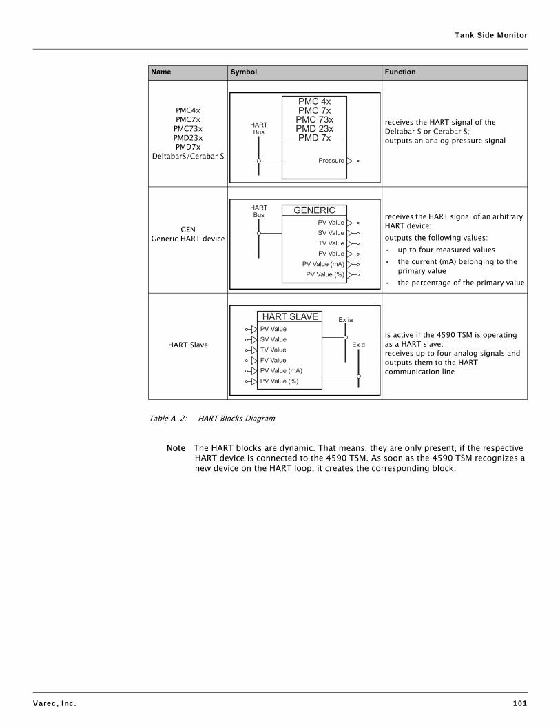
Tank Side Monitor
Varec, Inc. 101
Table A-2: HART Blocks Diagram
Note The HART blocks are dynamic. That means, they are only present, if the respective HART device is connected to the 4590 TSM. As soon as the 4590 TSM recognizes a new device on the HART loop, it creates the corresponding block.
PMC4x PMC7x PMC73x PMD23x PMD7x
DeltabarS/Cerabar S
receives the HART signal of the Deltabar S or Cerabar S; outputs an analog pressure signal
GEN Generic HART device
receives the HART signal of an arbitrary HART device:outputs the following values:• up to four measured values• the current (mA) belonging to the
primary value• the percentage of the primary value
HART Slaveis active if the 4590 TSM is operating as a HART slave; receives up to four analog signals and outputs them to the HART communication line
Name Symbol Function
PMD 7x
PMD 23x
PMC 73x
PMC 7x
PMC 4x
Pressure
HART
Bus
GENERIC
SV Value
PV Value
TV Value
FV Value
PV Value (mA)
PV Value (%)
HART
Bus
HART SLAVE
PV Value
SV Value
TV Value
FV Value
PV Value (mA)
PV Value (%)
Ex ia
Ex d

Appendix
102 Installation and Operations Manual
A.3.2.3 Internal function blocks
Name Symbol Function
AL-LLevel Alarm
AL-TTemperature Alarm
AL #1/AL #2Alarm
receives an analog signal; calculates 5 binary values according to the alarm points
Note The 4590 TSM contains 4 alarm blocks with the follow-ing designations:
• Level Alarm• Temperature Alarm• Alarm 1• Alarm 2
AL-L
AL-T
AL-#1
AL-#2
HH Alarm
HH Alarm
HH Alarm
HH Alarm
HH+H Alarm
HH+H Alarm
HH+H Alarm
HH+H Alarm
Value
Ref
Value
Ref
Value
Ref
Value
Ref
H Alarm
H Alarm
H Alarm
H Alarm
Any Alarm
Any Alarm
Any Alarm
Any Alarm
L Alarm
L Alarm
L Alarm
L Alarm
LL Alarm
LL Alarm
LL Alarm
LL Alarm
L+LL Alarm
L+LL Alarm
L+LL Alarm
L+LL Alarm

Tank Side Monitor
Varec, Inc. 103
Table A-3: Internal Function Blocks Diagram
TANKTank Functions
receives the measured values from the HART and the input blocks;performs the tank calculations and corrections;outputs the calculated tank values
Name Symbol Function
TANK
Level %
Level
Temp Ref
Vapour Ref
Air Temp Ref
Water Level Ref
P1 (Bot) Ref
P2 (Mid) Ref
P3 (Top) Ref
GP 1 Ref
GP 2 Ref
GP 3 Ref
GP 4 Ref
Element 1..16 Ref
Level Ref
Meas. Level
Temperature
Vapour Temp
Air Temp
Water Level
P1 (Bottom)
P2 (Middle)
P3 (Top)
Obs. Density
Lvl. Flow Rate
Vol. Flow Rate
GP 1 Value
GP 2 Value
GP 3 Value
GP 4 Value
Element 1..16
Tank Ref. Height

Appendix
104 Installation and Operations Manual
A.3.2.4 Field protocol blocks
Figure A-4: Field Protocol Blocks Diagram
Note Every 4590 TSM contains one of these blocks - corresponding to its field protocol. The field protocol block receives values from other blocks and outputs them to the fieldbus.
WM550
Temperature
Vapour Temp
Air Temp
Water Level
P1 (Bottom)
P2 (Middle)
P3 (Top)
Obs. Density
Lvl. Flow Rate
Vol. Flow Rate
GP 1 Value
GP 2 Value
GP 3 Value
GP 4 Value
Element 1..16
Tank Height
Alarm 1 Ref
Alarm 2 Ref
Alarm 3 Ref
Alarm 4 Ref
Alarm 5 Ref
Alarm 6 Ref
Alarm 7 Ref
Alarm 8 Ref
Meas. Level
Level %
LevelLoop 1
Loop 2
V1
Temperature
Vapour Temp
Water Level
P1 (Bottom)
P2 (Middle)
P3 (Top)
Obs. Density
GP 1 Value
GP 2 Value
Element 1..16
4..20mA Ref
Alarm Ref 1 (L)
Alarm Ref 2 (H)
SP 1 Ref
SP 2 Ref
SP 3 Ref
SP 4 Ref
Level
MODBUS
Temperature
Vapour Temp
Air Temp
Water Level
P1 (Bottom)
P2 (Middle)
P3 (Top)
Obs. Density
Lvl. Flow Rate
Vol. Flow Rate
GP 1 Value
GP 2 Value
GP 3 Value
GP 4 Value
Element 1..16
Value #1..8 Ref
4..20mA Ref
Discrete #1..8 Ref
Meas. Level
Level %
Level
Value #1..4
Discrete #1..4
BPM
Temperature
Vapour Temp
Air Temp
Water Level
P1 (Bottom)
P2 (Middle)
P3 (Top)
Obs. Density
Air Temp
HH Level Alarm
H Level Alarm
L Level Alarm
LL Level Alarm
Density Al Ref H
Density Al Ref L
Water Al Ref H
Water Al Ref L
DI Ref 1
DI Ref 2
Level
MARK SPACE
Temperature
Alarm Ref 1
Alarm Ref 2
Level
L&J
Temperature
Temp 2 Ref
Water Level
Obs. Density
DI Ref 1
DI Ref 2
Level
GPE
Temperature
4..20mA Ref
Contact Ref
Level

Tank Side Monitor
Varec, Inc. 105
A.3.3 Default block configuration
A.3.3.1 Default configuration for Sakura V1 (4590 TSM - *8*********)4)
Figure A-5: Default Configuration for Sakura V1 (4590 TSM - *8*********)4) Diagram
4) The alarm function blocks AL-1 and AL-2 are not shown in the diagram.
TANK
Level %
Level
Temp Ref
Vapour Ref
Air Temp Ref
Water Level Ref
P1 (Bot) Ref
P2 (Mid) Ref
P3 (Top) Ref
GP 1 Ref
GP 2 Ref
GP 3 Ref
GP 4 Ref
Element 1..16 Re f
Level Ref
Meas. Level
Temperature
Vapour Temp
Air Temp
Water Level
P1 (Bottom)
P2 (Middle)
P3 (Top)
Obs. Density
Lvl. Flow Rate
Vol. Flow Rate
GP 1 Value
GP 2 Value
GP 3 Value
GP 4 Value
Element 1..16
Tank Ref. Height
DISPLAYPrimary Value
Sec. Value 1
Sec. Value 2
Sec. Value 3
Sec. Value 4
DO #AValueRef
DO #BValueRef
I.S. DI #1Input
Value
I.S. AIValue
Input Value
Input Value %AL-L
HH Alarm
HH+ H A larm
ValueRef
H A larm
Any Alarm
L A larm
LL Alarm
L+LL Alarm
I.S. DI #2Input
Value
AO
Output Value
Value Ref
Output Value %
AL-T
HH Alarm
HH+ H A larm
ValueRef
H A larm
Any Alarm
L A larm
LL Alarm
L+LL Alarm
DI #AInput
Value
DI #BInput
Value
4590 TSM-****X******
4590 TSM-****X******
4590 TSM-*****X*****
4590 TSM-*****X*****
V1
Temperature
Vapour Temp
Water Level
P1 (Bottom)
P2 (Middle)
P3 (Top)
Obs. Density
GP 1 Value
GP 2 Value
Element 1..16
4..20mA Ref
Alarm Ref 1 (L)
Alarm Ref 2 (H )
SP 1 Ref
SP 2 Ref
SP 3 Ref
SP 4 Ref
Level
AO #2
Output Value
Value Ref
Output Value %

Appendix
106 Installation and Operations Manual
A.3.3.2 Default configuration for EIA-485 Modbus (4590 TSM - *4/5*********)5)
Figure A-6: Default Configuration for EIA-485 Modbus (4590 TSM - *4/5*********)5) Diagram
5) The alarm function blocks AL-1 and AL-2 are not shown in the diagram.
MODBUS
Temperature
Vapour Temp
Air Temp
Water Level
P1 (Bottom)
P2 (Middle)
P3 (Top)
Obs. Density
Lvl. Flow Rate
Vo l. Flow Rate
GP 1 Value
GP 2 Value
GP 3 Value
GP 4 Value
Element 1..16
Value #1..8 Ref
4..20mA Ref
Discrete #1..8 Ref
Meas. Level
Level %
Level
Value #1..4
Discrete #1..4
TANK
Level %
Level
Temp Ref
Vapour Ref
Air Temp Ref
Water Level Ref
P1 (Bot) Ref
P2 (Mid) Ref
P3 (Top) Ref
GP 1 Ref
GP 2 Ref
GP 3 Ref
GP 4 Ref
Element 1..16 Ref
Level Ref
Meas. Level
Temperature
Vapour Temp
Air Temp
Water Level
P1 (Bottom)
P2 (Middle)
P3 (Top)
Obs. Density
Lvl. Flow Rate
Vol. Flow Rate
GP 1 Value
GP 2 Value
GP 3 Value
GP 4 Value
Element 1..16
Tank Ref. Height
DISPLAYPrimary Value
Sec. Value 1
Sec. Value 2
Sec. Value 3
Sec. Value 4
DO #AValueRef
DO #BValueRef
I.S. DI #1Input
Value
I.S. AIValue
Input Value
Input Value %
AL-L
HH Alarm
HH+ H A larm
ValueRef
H A larm
Any Alarm
L A larm
LL Alarm
L+LL Alarm
I.S. DI #2Input
Value
AIValue
Input Value
Input Value %
AO
Output Value
Value Ref
Output Value %
AL-T
HH Alarm
HH+ H A larm
ValueRef
H A larm
Any Alarm
L A larm
LL Alarm
L+LL Alarm
DI #AInput
Value
DI #BInput
Value
4590 TSM-****X****** 4590 TSM-****X******
4590 TSM-*****X*****
4590 TSM-*5*********
4590 TSM-*****X*****
4590 TSM-*5*********

Tank Side Monitor
Varec, Inc. 107
A.3.3.3 Default configuration for Whessoematic WM550 (4590 TSM - *1*********)6)
Figure A-7: Default Configuration for Whessoematic WM550 (4590 TSM - *1*********)6) Diagram
6) The alarm function blocks AL-1 and AL-2 are not shown in the diagram.
TANK
Level %
Level
Temp Ref
Vapour Ref
Air Temp Ref
Water Level Ref
P1 (Bot) Ref
P2 (Mid) Ref
P3 (Top) Ref
GP 1 Ref
GP 2 Ref
GP 3 Ref
GP 4 Ref
Element 1..16 Ref
Level Ref
Meas. Level
Temperature
Vapour Temp
Air Temp
Water Level
P1 (Bottom)
P2 (Middle)
P3 (Top)
Obs. Density
Lvl. Flow Rate
Vol. Flow Rate
GP 1 Value
GP 2 Value
GP 3 Value
GP 4 Value
Element 1..16
Tank Ref. Height
DISPLAYPrimary Value
Sec. Value 1
Sec. Value 2
Sec. Value 3
Sec. Value 4
DO #AValueRef
DO #BValueRef
I.S. DI #1Input
Value
I.S. AIValue
Input Value
Input Value %
AL-L
HH Alarm
HH+ H A larm
ValueRef
H A larm
Any Alarm
L A larm
LL Alarm
L+LL Alarm
I.S. DI #2Input
Value
AO
Output Value
Value Ref
Output Value %
AL-T
HH Alarm
HH+ H A larm
ValueRef
H A larm
Any Alarm
L A larm
LL Alarm
L+LL Alarm
DI #AInput
Value
DI #BInput
Value
4590 TSM-****X****** 4590 TSM-****X******
4590 TSM-*****X***** 4590 TSM-*****X*****
WM550
Temperature
Vapour Temp
Air Temp
Water Level
P1 (Bottom)
P2 (Middle)
P3 (Top)
Obs. Density
Lvl. Flow Rate
Vo l. Flow Rate
GP 1 Value
GP 2 Value
GP 3 Value
GP 4 Value
Element 1..16
Tank Height
Alarm 1 Ref
Alarm 2 Ref
Alarm 3 Ref
Alarm 4 Ref
Alarm 5 Ref
Alarm 6 Ref
Alarm 7 Ref
Alarm 8 Ref
Meas. Level
Level %
LevelLoop 1
Loop 2
AO #2
Output Value
Value Ref
Output Value %

Appendix
108 Installation and Operations Manual
A.3.3.4 Default configuration for BPM (4590 TSM - *E*********)7)
Figure A-8: Default Configuration for BPM (4590 TSM - *E*********)7) Diagram
7) The alarm function blocks AL-1 and AL-2 are not shown in the diagram.
TANK
Level %
Level
Temp Ref
Vapour Ref
Air Temp Ref
Water Level Ref
P1 (Bot) Ref
P2 (Mid) Ref
P3 (Top) Ref
GP 1 Ref
GP 2 Ref
GP 3 Ref
GP 4 Ref
Element 1..16 Ref
Level Ref
Meas. Level
Temperature
Vapour Temp
Air Temp
Water Level
P1 (Bottom)
P2 (Middle)
P3 (Top)
Obs. Density
Lvl. Flow Rate
Vol. Flow Rate
GP 1 Value
GP 2 Value
GP 3 Value
GP 4 Value
Element 1..16
Tank Ref. Height
DISPLAYPrimary Value
Sec. Value 1
Sec. Value 2
Sec. Value 3
Sec. Value 4
DO #AValueRef
DO #BValueRef
I.S. DI#1Input
Value
I.S. AIValue
Input Value
Input Value %
AL-L
HH Alarm
HH+ H A larm
ValueRef
H A larm
Any Alarm
L A larm
LL Alarm
L+LL Alarm
I.S. DI#2Input
Value
AIValue
Input Value
Input Value %
AO
Output Value
Value Ref
Output Value %
AL-T
HH Alarm
HH+ H A larm
ValueRef
H A larm
Any Alarm
L A larm
LL Alarm
L+LL Alarm
DI #AInput
Value
DI #BInput
Value
4590 TSM-****X******
4590 TSM-****X******
4590 TSM-*****X*****
4590 TSM-*****X*****
BPM
Temperature
Vapour Temp
Air Temp
Water Level
P1 (Bottom)
P2 (Middle)
P3 (Top)
Obs. Density
Air Temp
HH Level Alarm
H Level Alarm
L Level Alarm
LL Level Alarm
Density Al Ref H
Density Al Ref L
Water Al Ref H
Water Al Ref L
DI Ref 1
DI Ref 2
Level

Tank Side Monitor
Varec, Inc. 109
A.3.3.5 Default configuration for Mark/Space (4590 TSM - *2/3*********)8)
Figure A-9: Default Configuration for Mark/Space (4590 TSM - *2/3*********)8) Diagram
8) The alarm function blocks AL-1 and AL-2 are not shown in the diagram.
TANK
Level %
Level
Temp Ref
Vapour Ref
Air Temp Ref
Water Level Ref
P1 (Bot) Ref
P2 (Mid) Ref
P3 (Top) Ref
GP 1 Ref
GP 2 Ref
GP 3 Ref
GP 4 Ref
Element 1..16 Ref
Level Ref
Meas. Level
Temperature
Vapour Temp
Air Temp
Water Level
P1 (Bottom)
P2 (Middle)
P3 (Top)
Obs. Density
Lvl. Flow Rate
Vol. Flow Rate
GP 1 Value
GP 2 Value
GP 3 Value
GP 4 Value
Element 1..16
Tank Ref. Height
DISPLAYPrimary Value
Sec. Value 1
Sec. Value 2
Sec. Value 3
Sec. Value 4
DO #AValueRef
DO #BValueRef
I.S. DI#1Input
Value
I.S. AIValue
Input Value
Input Value %
AL-L
HH Alarm
HH+ H A larm
ValueRef
H A larm
Any Alarm
L A larm
LL Alarm
L+LL Alarm
I.S. DI#2Input
Value
AIValue
Input Value
Input Value %
AO
Output Value
Value Ref
Output Value %
AL-T
HH Alarm
HH+ H A larm
ValueRef
H A larm
Any Alarm
L A larm
LL Alarm
L+LL Alarm
DI #AInput
Value
DI #BInput
Value
4590 TSM-****X****** 4590 TSM-****X******
4590 TSM-*****X***** 4590 TSM-*****X*****
MARK SPACE
Temperature
Alarm Ref 1
Alarm Ref 2
Level

Appendix
110 Installation and Operations Manual
A.3.3.6 Default configuration for L&J Tankway (4590 TSM - *7*********)9)
Figure A-10: Default Configuration for L&J Tankway (4590 TSM - *7*********)9) Diagram
9) The alarm function blocks AL-1 and AL-2 are not shown in the diagram.
TANK
Level %
Level
Temp Ref
Vapour Ref
Air Temp Ref
Water Level Ref
P1 (Bot) Ref
P2 (Mid) Ref
P3 (Top) Ref
GP 1 Ref
GP 2 Ref
GP 3 Ref
GP 4 Ref
Element 1..16 Ref
Level Ref
Meas. Level
Temperature
Vapour Temp
Air Temp
Water Level
P1 (Bottom)
P2 (Middle)
P3 (Top)
Obs. Density
Lvl. Flow Rate
Vol. Flow Rate
GP 1 Value
GP 2 Value
GP 3 Value
GP 4 Value
Element 1..16
Tank Ref. Height
DISPLAYPrimary Value
Sec. Value 1
Sec. Value 2
Sec. Value 3
Sec. Value 4
DO #AValueRef
DO #BValueRef
I.S. DI #1Input
Value
I.S. AIValue
Input Value
Input Value %
AL-L
HH Alarm
HH+ H A larm
ValueRef
H A larm
Any Alarm
L A larm
LL Alarm
L+LL Alarm
I.S. DI #2Input
Value
AIValue
Input Value
Input Value %
AO
Output Value
Value Ref
Output Value %
AL-T
HH Alarm
HH+ H A larm
ValueRef
H A larm
Any Alarm
L A larm
LL Alarm
L+LL Alarm
DI #AInput
Value
DI #BInput
Value
4590 TSM-****X****** 4590 TSM-****X******
4590 TSM-*****X***** 4590 TSM-*****X*****
L&J
Temperature
Temp 2 Ref
Water Level
Obs. Density
DI Ref 1
DI Ref 2
Level

Tank Side Monitor
Varec, Inc. 111
A.3.3.7 Default configuration for GPE (4590 TSM - *G*********)10)
Figure A-11: Default Configuration for GPE (4590 TSM - *G*********)10) Diagram
10) The alarm function blocks AL-1 and AL-2 are not shown in the diagram.
TANK
Level %
Level
Temp Ref
Vapour Ref
Air Temp Ref
Water Level Ref
P1 (Bot) Ref
P2 (Mid) Ref
P3 (Top) Ref
GP 1 Ref
GP 2 Ref
GP 3 Ref
GP 4 Ref
Element 1..16 Ref
Level Ref
Meas. Level
Temperature
Vapour Temp
Air Temp
Water Level
P1 (Bottom)
P2 (Middle)
P3 (Top)
Obs. Density
Lvl. Flow Rate
Vol. Flow Rate
GP 1 Value
GP 2 Value
GP 3 Value
GP 4 Value
Element 1..16
Tank Ref. Height
DISPLAYPrimary Value
Sec. Value 1
Sec. Value 2
Sec. Value 3
Sec. Value 4
DO #AValueRef
DO #BValueRef
I.S. DI #1Input
Value
I.S. AIValue
Input Value
Input Value %
AL-L
HH Alarm
HH+ H A larm
ValueRef
H A larm
Any Alarm
L A larm
LL Alarm
L+LL Alarm
I.S. DI #2Input
Value
AIValue
Input Value
Input Value %
AO
Output Value
Value Ref
Output Value %
AL-T
HH Alarm
HH+ H A larm
ValueRef
H A larm
Any Alarm
L A larm
LL Alarm
L+LL Alarm
DI #AInput
Value
DI #BInput
Value
4590 TSM-****X****** 4590 TSM-****X******
4590 TSM-*****X***** 4590 TSM-*****X*****
L&J
Temperature
Temp 2 Ref
Water Level
Obs. Density
DI Ref 1
DI Ref 2
Level

Appendix
112 Installation and Operations Manual

Varec, Inc. 113
Index
AAC supply . . . . . . . . . . . . . . . . . . . . . . . . . . . . . . 85Accessories . . . . . . . . . . . . . . . . . . . . . . . . . . . . 69Accuracy. . . . . . . . . . . . . . . . . . . . . . . . . . . . . . . 86Ambient conditions . . . . . . . . . . . . . . . . . . . . . . . 86Ambient temperature . . . . . . . . . . . . . . . . . . . . . 86Application . . . . . . . . . . . . . . . . . . . . . . . . . . . . . 93Automatic HART scan . . . . . . . . . . . . . . . . . . . . . 3Auxiliary energy . . . . . . . . . . . . . . . . . . . . . . . . . 85
CCable entries . . . . . . . . . . . . . . . . . . . . . . . . . . . 87cleaning . . . . . . . . . . . . . . . . . . . . . . . . . . . . . . . 63Connecting a 4-wire radar gauge to the non-I.S./ field protocol side . . . . . . . . . . . . . . . . . . . . . . . 25Connecting a 6005 STG to the Non-I.S. HARTinput . . . . . . . . . . . . . . . . . . . . . . . . . . . . . . . . . . 26Connecting field protocols . . . . . . . . . . . . . . . . . 21Connecting HART instruments . . . . . . . . . . . . . . 31Connecting the 6005 STG . . . . . . . . . . . . . . . . . 31Connecting the auxiliary energy . . . . . . . . . . . . . 22Connecting the discrete in and output . . . . . . . . 24Connecting the Non-I.S. 4...20 mA analog input 22Connecting the Non-I.S. 4...20 mA analog output 23Connecting the secondary Non-I.S. 4...20 mAanalog output . . . . . . . . . . . . . . . . . . . . . . . . . . . 23Construction . . . . . . . . . . . . . . . . . . . . . . . . . . . . 87
DDC supply . . . . . . . . . . . . . . . . . . . . . . . . . . . . . . 85Declaration of Contamination . . . . . . . . . . . . . . . . 6Declaration of contamination . . . . . . . . . . . . . . . 66Design, dimensions . . . . . . . . . . . . . . . . . . . . . . 87Device Status . . . . . . . . . . . . . . . . . . . . . . . . . . . 41
EEditing parameters . . . . . . . . . . . . . . . . . . . . . . . 43Electromagnetic compatibility (EMC) . . . . . . . . . 87Entering the menu . . . . . . . . . . . . . . . . . . . . . . . 41Example of block linking . . . . . . . . . . . . . . . . . . . 48
FFCC approval . . . . . . . . . . . . . . . . . . . . . . . . . . . . 5Function blocks and data flow . . . . . . . . . . . . . . 47Function blocks and data transfer . . . . . . . . . . . 97Fuse . . . . . . . . . . . . . . . . . . . . . . . . . . . . . . . . . . 85
GGeneral key combinations . . . . . . . . . . . . . . . . . 35Grounding of the fieldbus screen . . . . . . . . . . . . 22
HHazardous areas . . . . . . . . . . . . . . . . . . . . . . . . . 5
IIngress protection . . . . . . . . . . . . . . . . . . . . . . . . 86Inputs and Outputs . . . . . . . . . . . . . . . . . . . . . . . 81
KKey operation . . . . . . . . . . . . . . . . . . . . . . . . . . . . 3
LLinking Digital Inputs . . . . . . . . . . . . . . . . . . . . . . 47Linking sensors to function blocks . . . . . . . . . . . 47
MMain menu . . . . . . . . . . . . . . . . . . . . . . . . . . . . . 41Mechanical construction . . . . . . . . . . . . . . . . . . . 87Modbus termination. . . . . . . . . . . . . . . . . . . . . . . . 3Mounting on horizontal rail . . . . . . . . . . . . . . . . . 15Mounting on vertical rail . . . . . . . . . . . . . . . . . . . 14
NNavigation within the menu . . . . . . . . . . . . . . . . . 42
OOperating principle . . . . . . . . . . . . . . . . . . . . . . . 93Overvoltage protection . . . . . . . . . . . . . . . . . . . . 87
PPC board 4590 TSM . . . . . . . . . . . . . . . . . . . . . . 65Performance characteristics . . . . . . . . . . . . . . . . 86Power consumption. . . . . . . . . . . . . . . . . . . . . . . 85
QQuitting the menu . . . . . . . . . . . . . . . . . . . . . . . . 44
RRelay output module . . . . . . . . . . . . . . . . . . . . . . 72Repairs to Ex-approved devices . . . . . . . . . . . . . 63Resolution . . . . . . . . . . . . . . . . . . . . . . . . . . . . . . 86Return . . . . . . . . . . . . . . . . . . . . . . . . . . . . . . . . . 66
SScan time . . . . . . . . . . . . . . . . . . . . . . . . . . . . . . 86Sealing of the 4590 TSM. . . . . . . . . . . . . . . . . . . 46Shortcut menu. . . . . . . . . . . . . . . . . . . . . . . . . . . 41Softkeys . . . . . . . . . . . . . . . . . . . . . . . . . . . . . . . 35Software locking . . . . . . . . . . . . . . . . . . . . . . . . . 44Software unlocking . . . . . . . . . . . . . . . . . . . . . . . 44Standard mechanical diagram for all I/O modules 69Storage temperature . . . . . . . . . . . . . . . . . . . . . . 86System Integration . . . . . . . . . . . . . . . . . . . . . . . 94
TTerminal assignment . . . . . . . . . . . . . . . . . . . . . . 29Terminal assignment of the field protocol/hostside . . . . . . . . . . . . . . . . . . . . . . . . . . . . . . . . . . . 20

Varec, Inc. 114
The function blocks of the 4590 TSM. . . . . . . . . 98
VValidation of Weight & Measure approvedmeasurements . . . . . . . . . . . . . . . . . . . . . . . . . . 49
WW&M hardware locking switch . . . . . . . . . . . . . . 45Wall mounting. . . . . . . . . . . . . . . . . . . . . . . . . . . 14Weight . . . . . . . . . . . . . . . . . . . . . . . . . . . . . . . . 87

Return Goods Decontamination Form For internal use only: Confidential & Proprietary FRM128GVAE0906 Page 1 of 1
An SAIC Company
Because of legal regulations and for the safety of our employees and operating equipment, we require this document to be completed, with your signature, and faxed to us for review before your order can be handled. Please fax directly to 770-810-9456 attention Customer Service.
Customer Information
Company Name:
Contact Name:
Address:
Tel:
Fax:
Email:
Product Information
RMA No.:
No. of Pieces in RMA:
Part Number:
Serial Number:
Assigned Technician:
Medium and Warning
Please select one, include safety data sheet and if necessary, special handling instructions.
Medium Flammable Toxic Corrosive Harmful/irritant Other* Harmless
Process Medium:
Medium for cleaning:
Returned part cleaned with:
*Other: Explosive, oxidizing; dangerous for the environment; biological risk; radioactive. We hereby certify that this declaration is filled out truthfully and completely to the best of our knowledge. We further certify that the returned part(s) have been carefully cleaned. To the best of our knowledge they are free from and residues in dangerous quantities. Signature: ____________________________ Date: ______________________
Varec, Inc. • 5834 Peachtree Corners East • Norcross (Atlanta), Georgia 30092 Tel: (770) 447-9202 • Fax: (770) 662-8939
www.varec.com


Varec, Inc. • 5834 Peachtree Corners East, Norcross (Atlanta), GA 30092 USATel: +1 (770) 447-9202 • Fax: +1 (770) 662-8939
www.varec.com
© 2006 Varec, Inc. All Rights Reserved. This document is for information purposes only. Varec, Inc. makes no warranties, express or implied, in this summary. The names of actual companies and products mentioned herein may be the trademarks of their respective owners.
Document CodeIOM029FVAE0510


![SWISS-WAY CAVALIER ET -B7532- - Fieldstone Braunvieh · swiss-way cavalier et -b7532- ! !! ! ! ! negro!mm!4451+[sw]4451+!!!! ! ! normann!+9323+!!!! !!! ! !! ! ! juvelmm!4590+[sw]4590+!!!!](https://img.dokumen.tips/doc/110x75/5e894ead720a7a44a31ffd47/swiss-way-cavalier-et-b7532-fieldstone-braunvieh-swiss-way-cavalier-et-b7532-.jpg)