Embed Size (px)
Citation preview

Polytron FXOperating Manual

1
For Your Safety
Strictly follow the assembly and installation instructionsThe instrument must be calibrated at intervals recommended in the operatingmanual or more frequently according to specific use and applications.
Do not calibrate the instrument in the presence of an operating radiotransmitter.
Use in areas subject to explosion hazardsThe sensor must be screwed in at least 5 threads to maintain the explosionproof rating.If the extra port at the 3 or 9 o’clock position is not to be used for wiringpurposes, the supplied plug must be screwed in completely to maintain theexplosion proof rating.Equipment or components which have been tested and approved according tothe national or European regulations on electrical equipment in rooms subjectto explosion hazards, may be used only under the conditions specified in theapproval.Modifications of components or the use of faulty or incomplete parts are notpermitted. In the case of repairs to equipment or components of this type, thenational regulations must be observed.
MaintenanceDräger warrants this instrument to be free of defects in material andworkmanship for a period of one (1) year from date of purchase. Drägerwarrants the sensor for a period of one (1) year from the date of purchase.
Liability for proper function or damageThe liability for the proper function is irrevocably transferred to the owner oroperator to the extent that the transmitter is serviced or repaired by personnelnot employed or authorized by Draeger Service or if the transmitter is used in amanner not conforming to its intended use.
Dräger cannot be held responsible for damage caused by noncompliance withthe recommendations given above. The warranty and liability provisions of theterms of sale and delivery of Dräger are likewise not modified by therecommendations given above.
Draeger Safety, Inc.
For Your Safety
2
Contents
For Your Safety .......................................................................................................1
1 Introduction .........................................................................................................41.1 Intended Use ......................................................................................................... 41.2 Design .................................................................................................................... 4
1.2.1 Aluminum Version ................................................................................... 41.2.2 Stainless Steel Version .......................................................................... 5
2 Operation .............................................................................................................62.1 Installation .............................................................................................................. 62.2 Replacing the Sensor ......................................................................................... 72.3 Change Gas Category of Polytron FX IR ........................................................ 8
3 Menu .....................................................................................................................93.1 Menu Navigation .................................................................................................. 93.2 Changing Parameter Values/Status ................................................................ 93.3 Exiting the Menu ................................................................................................ 103.4 Menu Items ......................................................................................................... 10
3.4.1 Gas Conc .............................................................................................. 103.4.2 Password ............................................................................................... 10
3.4.2.1 Password Adj ....................................................................... 103.4.3 Zero Adj ................................................................................................. 103.4.4 Span Adj ................................................................................................ 113.4.5 FSD Adj .................................................................................................. 113.4.6 A1 Adj ..................................................................................................... 113.4.7 A2 Adj ..................................................................................................... 113.4.8 A1 Lat ..................................................................................................... 113.4.9 A2 Lat ..................................................................................................... 113.4.10 A1 Acn .................................................................................................... 113.4.11 A2 Acn .................................................................................................... 113.4.12 Cal Sig .................................................................................................... 113.4.13 LCD On/Off .......................................................................................... 11
3.5 Output and Display Variations ........................................................................ 12
4 Maintenance..................................................................................................... 134.1 Calibration .......................................................................................................... 13
4.1.1 Calibration Procedure ........................................................................ 134.1.1.1 Zero Calibration ................................................................... 134.1.1.2 Span Calibration .................................................................. 14
4.2 Error Messages ................................................................................................. 15
Contents

3
Contents
5 Sensor Principle .............................................................................................. 165.1 Operating Principle for DraegerSensor PR and LC ................................. 165.2 Contaminating Gases for DraegerSensor PR and LC ............................. 165.3 Operating Principle for DraegerSensor IR ................................................. 17
6 Technical Information ..................................................................................... 186.1 Approvals ............................................................................................................ 18
6.1.1 Aluminum Version ................................................................................ 186.1.2 Stainless Steel Version ....................................................................... 18
6.2 Signal Transmission to Central Control Unit .............................................. 186.3 Voltage of Power Supply ................................................................................. 186.4 Physical Specifications .................................................................................... 19
6.4.1 Aluminum Version ................................................................................ 196.4.2 Stainless Steel Version ....................................................................... 19
6.5 Environmental Parameters .............................................................................. 196.6 Ambient Influences ........................................................................................... 19
7 Order Information ........................................................................................... 207.1 Replacement Sensors ...................................................................................... 207.2 Accessories ........................................................................................................ 207.3 Spare Parts ......................................................................................................... 20
Addresses ............................................................................................................. 25

4
1 Introduction
1.1 Intended UseThe Polytron FX is an explosion-proof transmitter for the detection ofcombustible gases and vapors in ambient air. The transmitter is designed to beinstalled in permanent locations and is approved for use in hazardous,classified areas (See Section 6.1, Approvals).
1.2 DesignThe transmitter is powered by 16 to 30 VDC. Gas concentrations, errormessages, and software menu choices are displayed on a 3 digit LCD display.Access to the software is obtained by tapping a magnetic wand on the glassviewport at the appropriate arrow indicators. In this way, the instrument can beconfigured, calibrated and maintained non-intrusively, so declassification of thearea is not necessary for these procedures.
1.2.1 Aluminum VersionThe Polytron FX transmitter is housed in a powder-coated aluminum enclosurewith 3/4” NPT threaded ports located at the 3 and 9 o’clock positions. Thesensor is located at the 6 o’clock position.
IntroductionIntended UseDesign
Figure 1: Polytron FX and Polytron FX IR, aluminum version

5
1.2.2 Stainless Steel VersionThe Polytron FX transmitter is housed in an enclosure with 3/4” NPT threadedports located at the 12 and 6 o’clock positions.
Figure 1a: Polytron FX and Polytron FX IR, stainless steel version
IntroductionIntended Use
Design
6
2 Operation
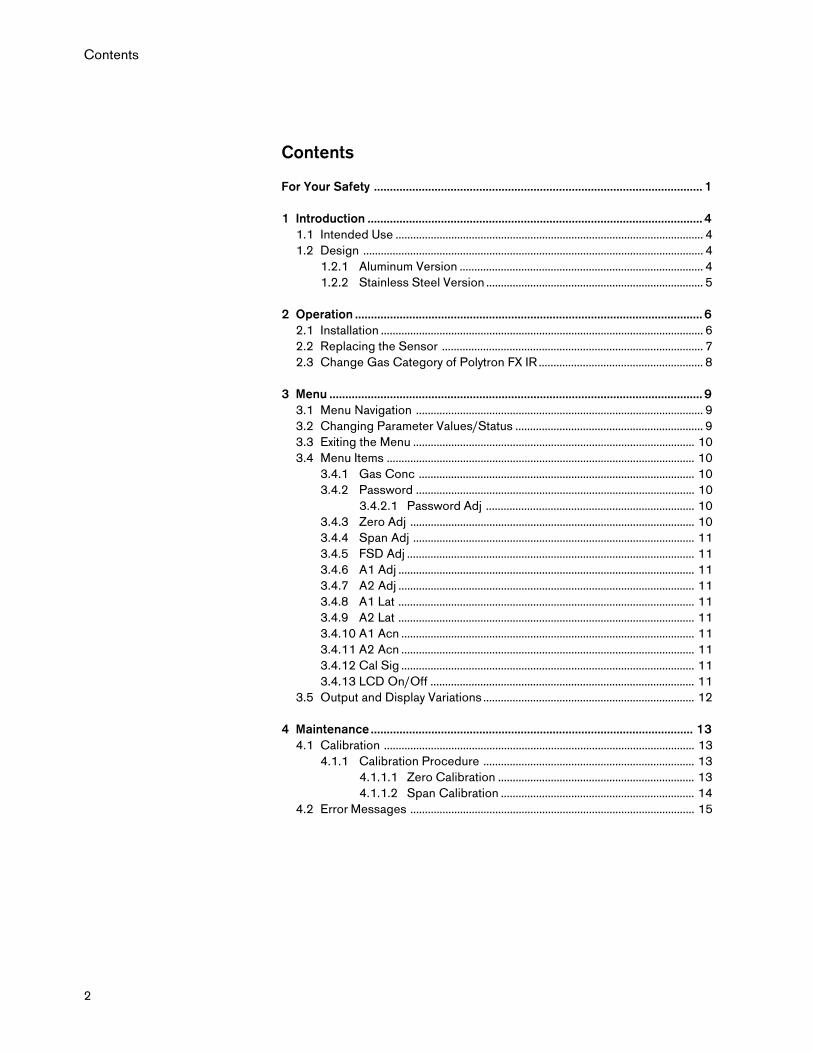
2.1 InstallationMount the instrument at the appropriate height for the gas to be detected,taking into account the density of the gas, air flow patterns in the room, andpersonnel considerations. Responsibility for correct placement of thePolytron FX rests with the end user; if in doubt about placement, consult withDraeger application engineers.
Polytron FX is a three-wire device powered by 16 to 30 V DC. Wiring terminalsare located on the back of the PCB; pull out the bezel, by grasping the notcheson either side of the display with your fingers and pulling up (Figure 2).
Connect the wires as shown in Figure 3.
OperationInstallation
Figure 3: Connections for 24 V DC power supply/controller
Figure 2: Pulling out the bezel
grasp notcheswith fingersand pull up
CAUTIONNever insertobjects into
finger notches.

7
Wiring to and from controllers/power supplies must be run through sealedconduit to maintain the explosion-proof status. If only one of the threaded inletports is used for external wiring, the other must be sealed with the blankingplug included with the unit (Figure 4).
2.2 Replacing the SensorTo replace the sensor, see Figure 5 for details:
• Declassify the area according to local procedures.
• Turn off power to the unit.
• Remove the housing cover.
• Remove the main PCB, which is attached to the bezel, by grasping thenotches on either side of the display with your fingers and pulling up(Figure 2).
• Unplug the sensor cable.
• Unscrew the Dräger Sensor.
Installing the Sensor
Figure 4: Wiring through sealed conduit
BlankingPlug
Conduit

8
Replacing the Sensor
• Insert the sensor wires through the threaded port in the housing.
• Screw the Dräger Sensor into the port. Five threads must be engagedto ensure explosion-proof status.
• Plug the wires into the socket on the main PCB.
• Re-install sensor electronics by pushing the bezel and main PCB back intoplace.
• Screw housing cover back onto the unit, being careful not to damage thethreads. The cover must be screwed on tightly to compress the o-ring tomaintain explosion-proof status.
• Apply power to the unit.
• Calibrate instrument per section 4.1, Calibration.
• Always test a newly-installed sensor with target gas to verify proper operation.
2.3 Change Gas Category of Polytron FX IRSee manual 9023843. This has to be done at the DraegerSensor IR.
Figure 5: Replacing the sensor
Housing Cover
Bezel
Main PCB
Plug wires into socketon Main PCB
Threaded Port
Sensor Wires
DraegerSensorPR or LC
Housing
DraegerSensor IR

9
Figure 6: Arrows indicate the location ofmagnetic contact switches on front display panel
Up
DownEnter
MenuMenu Navigation
Changing Parameter Values/StatusExiting the Menu
3 Menu
In the standard operating mode, the Gas Concentration of the target gas will bedisplayed. To access the software menu, tap the magnetic wand once againstthe glass viewport above the Down arrow. The display shows the first menuitem, Adj Zero. The displays flashes ‘-0-’, ‘Adj’, and then shows the target gasconcentration.
3.1 Menu NavigationTap the magnetic wand over the Up and Down arrows to scroll through themenu selections. If the magnetic wand is held over the switch for> 0.5 second, this will be considered multiple taps and the menu will scroll.When you reach the last item (LCD On/Off), the menu will bottom-out, and youwill have to use the Up arrow to scroll back up through the menu.The active menu item as well as its current value or status will flash on thedisplay as it scrolls.
NOTEThe instrument is designed for the magnetic wand to be used with the
housing cover in place. If the housing cover is not in place, then themagnetic wand may not work properly.
3.2 Changing Parameter Values/StatusTo enter a new value, or change a status, tap Enter with the magnetic wandwhen the desired menu item is displayed. The current value or status will flashto indicate a change to data entry mode. The Up and Down arrows allow you toadjust the value of a numerical parameter or to toggle between preset choices.Once the display shows the desired value or choice, tap Enter to validate thenew parameter. This will take you back to the menu, where you can scroll toanother menu item, if desired.

10
3.3 Exiting the MenuTo get back into the standard measurement mode, just scroll to the GasConcentration menu item at the top of the menu. The actual gas concentrationwill be displayed.
3.4 Menu Items
3.4.1 Gas ConcDisplays the current value of the concentration of the target gas in % LEL.This field is read-only, and cannot be modified by the operator.
3.4.2 PasswordThe use of a password is optional with the Polytron FX. A password consists ofa 3-digit number from 000 to 999; a value of 000 disables password protectionand allows anyone to access the software interface. The instrument is deliveredwith the password set to 000.
If a password has been set, it must be entered to gain access to the softwaremenu. Tap the magnetic wand over the Down arrow until the ‘PAS’ menu item isdisplayed. The 3-digit LCD will then show ‘000’, with the first zero on the leftblinking. Use the Up and Down arrows to increment or decrement this digit,then tap Enter. The second (middle) digit will blink, and the correct value shouldbe set using the Up and Down arrows as before. Repeat the process for thethird digit. Tap Enter when the full password is displayed. If the displayed valuematches the set password, you will gain access to the rest of the menu. If anincorrect password is entered, the instrument will return to the measurementmode.
3.4.2.1 Password AdjUse the Down arrow to scroll to the last menu item, Password Adjust. Thedisplay will show the message ‘PAS’, ‘ADJ’, ‘000’.
NOTEIf a password other than 000 has already been entered,
that number will appear in place of ‘000’.
Tapping the magnetic wand over Enter causes the 3-digit display to flash. Tapthe Up or Down arrows to scroll the value to the desired new password. Thedisplay will stop scrolling at a maximum value of 999 or a minimum of 000; itwill not roll over.
Tap Enter when the desired password is displayed to accept this as the newpassword. Once a password is set, you will have to enter it to gain access to themenu.
3.4.3 Zero AdjAllows you to adjust the zero reference point of the sensor when no target gasis present, such as during calibration. See Section 4.1.1, CalibrationProcedure, for details.
Exiting the MenuMenu Items

11
3.4.4 Span AdjAllows you to adjust the displayed gas concentration to match the knownconcentration of an applied calibration gas. For example, if a 50% LELcalibration gas is applied to the sensor, the Span Adj value should be adjustedto 50 once the sensor reading has stabilized. See Section 4.1.1, CalibrationProcedure, for details.
3.4.5 FSD AdjThe Full Scale Deflection is fixed at 100% LEL for the Polytron FX andPolytron FX IR or 10% LEL for the Polytron FX LC.
3.4.6 A1 AdjThis menu item is not active for the Polytron FX.
3.4.7 A2 AdjThis menu item is not active for the Polytron FX.
3.4.8 A1 LatThis menu item is not active for the Polytron FX.
3.4.9 A2 LatThis menu item is not active for the Polytron FX.
3.4.10 A1 AcnThis menu item is not active for the Polytron FX.
3.4.11 A2 AcnThis menu item is not active for the Polytron FX.
3.4.12 Cal SigCalibration signal is the signal that is transmitted by the 4 to 20mA outputanytime you access the software menu. It is user-selectable. The twopossibilities are:
a steady 3 mA signal
an oscillating 3 to 5mA signal with a frequency of 1 Hz
The default value is a steady 3 mA signal.
3.4.13 LCD On/OffThis feature allows you to turn the LCD output off if the desired, effectivelyturning the Polytron FX into a non-display instrument. The 4 to 20mA outputremains active independent of the LCD state. If the LCD is Off, pressing theDown arrow when in measurement mode still gives you access to the softwarefunctions.
Menu Items

12
3.5 Output and Display VariationsThe following table shows the status of the 4 to 20 mA output, and the LCDdisplay for various conditions.
Condition Analog Output LCD Display
Warming-up actual signal actual signal
After warm-up actual signal actual signal
After power outage actual signal actual signal
New sensor installed actual signal actual signal
Sensor removed signal “pls con snr”
Hardware fault signal “flt”
Microprocessor lock-up signal frozen display
In menu maintenance signal menu function
In cal modes maintenance signal cal function displays
The “actual signal” means the unmodified real-time signal in the circuit.
The maintenance signal is the 3 to 5mA oscillating signal, or the steady 3 mAsignal chosen in the “cal sig” menu function.
Output and Display Variations

13
4 Maintenance
4.1 Calibration
4.1.1 Calibration Procedure
Calibration of this unit must be performed at regular intervals as detailed in thesensor data sheet.
DraegerSensor IR:If the zero signal has drifted significantly, or a calibration fails: calibrate theDraegerSensor IR first (see manual P/N 9023843), then continue with thecalibration procedure for Polytron FX.
4.1.1.1 Zero Calibration• Attach the pressure regulator to the nitrogen (N2) or Zero Air calibration gas
cylinder.
DraegerSensor PR and LC:
• Fit the calibration adapter tightly to the end of the sensor.
Draeger Sensor IR:
MaintenanceCalibration
Figure 7: Calibration

14
• Connect the tubing to the barbed fitting of the sensor.
• IMPORTANT: Turn the gas on and allow to flow for at least one minute beforeproceeding.
• Scroll through software menu to Zero Adj and tap Enter. The current zerovalue will be displayed.
• Wait for the zero to stabilize.
• If the display is not already reading zero, trim the stabilized value to zero onthe display using the Up and Down arrows.
• Accept the value by tapping Enter with the magnetic wand.
• Turn off the gas flow and remove the calibration adapter from the sensor, ordisconnect tubing.
NOTEAmbient air can be used to zero the sensor instead of nitrogen orZero Air if the area is known to be free of the target gas or any gas
to which the sensor may be cross-sensitive (as listed on thesensor data sheet). In this case, no cylinder or calibration
adapter is needed for the zero calibration.
4.1.1.2 Span CalibrationWARNING
Never adjust the span before completing zero adjustment. Performingthese operations out of order will cause the calibration to be faulty.
• Attach the pressure regulator to the calibration gas cylinder.
DraegerSensor PR and LC:
• Fit the calibration adapter tightly to the end of the sensor.
Draeger Sensor IR:
• Connect the tubing to the barbed fitting of the sensor.
• IMPORTANT: Turn the gas flow on and allow to flow for at least one minutebefore proceeding.
• Scroll through software menu to Span Adj and tap Enter. The span value willbe displayed.
• Wait for the span value to stabilize.
• Using the Up and Down arrows, trim the stabilized value to the calibration gasconcentration that is being applied to the sensor. If the sensor has reachedthe end of its life, the span value will not be able to be reached. In this case,replace the sensor.
• Accept the value by tapping Enter with the magnetic wand.
• Turn off the gas flow and remove the calibration adapter from the sensor, ordisconnect tubing.
Calibration

15
Error Messages
4.2 Error Messages
Error Code Condition Solution
Pls Con Snr No sensor is connected, 1) Connect sensorsensor connection is bad, 2) Check to ensure sensoror sensor “bead” is open is seated in connector
3) Contact Draeger Safetytechnical service
Snr Err Sensor EEPROM data Contact Draeger Safetyis corrupted technical service
Flt Hardware fault Contact Draeger Safetytechnical service
AFE Err Wrong software version 1) Install most recent AFEinstalled in the Analog softwareFront End (AFE) 2) Contact Draeger Safety
technical service
AFE Out AFE microcontroller is out Contact Draeger Safetyof its socket, technical serviceor not installed

16
5 Sensor Principle
5.1 Operating Principle for DraegerSensor PRand LC
The DrägerSensor is a transducer for measuring the partial pressure ofcombustible gases and vapors contained in ambient air. It uses the heat-of-combustion principle.
The monitored air diffuses through the sintered metal disc into the sensor.There the mixture of combustible gases and vapors are catalytically combustedat a heated detector element (pellistor). The monitored air supplies the Oxygenrequired for the combustion. Due to the resulting heat-of-combustion, thedetector element gets hotter. This increase in heat causes a change ofresistance in the detector element, which is proportional to the concentrationof the mixture of combustible gases and vapors in the monitored air.
In addition to the catalytically active detector element, there is an inactivecompensator element. Both elements are parts of a Wheatstone bridge.Thus environmental effects like changes in temperature or humidity arealmost entirely compensated.
5.2 Contaminating Gases for DraegerSensor PRand LC
Vaporous silicon- and lead-compounds, sulfurous compounds such ashydrogen sulfide and sulfur dioxide, phosphorous compounds such asphosphine. Acidic vapors such as hydrogen fluoride, hydrogen chloride,hydrogen bromide and halogenated organic compounds such as refrigerantsand tri- or tetrachloroethene.
A calibration check might be necessary, if the sensor was exposed to a highconcentration of combustible gases or vapors for an extended period of timeor to contaminants as listed above.
Sensor PrincipleOperating Principle for DraegerSensor PR and LCContaminating Gases for DraegerSensor PR and LC
Principle of operation
1 Sintered metal2 Detector bead3 Sensor housing4 Compensator bead

17
5.3 Operating Principle for DraegerSensor IRThe DrägerSensor IR infrared gas sensor is a gas transmitter designed todetermine the concentration of gases and vapors in the ambient air. Theprinciple of measurement is based on the concentration-dependent absorptionof infrared radiation in measured gases.
The monitored ambient air diffuses through sintered material into theflameproof housing of a measuring cuvette. The broad-band light emitted by theradiator passes through the gas in the cuvette and is reflected by the cuvettewalls from where it is directed towards the inlet window of a dual elementdetector. One channel of the detector measures the gas-dependent lighttransmission of the cuvette (measuring channel), the other channel is used asreference. The ratio between measuring and reference signal is used todetermine the gas concentration in the cuvette. The cuvette is heated to avoidcondensation of the atmosphere’s moisture content.
Internal electronics and software are used to calculate the concentration. As anoutput signal, the gas sensor emulates the half bridge of a catalytic Ex sensor.
Die to its robust design and the measuring method the gas sensor has longmaintenance and calibration intervals (see manual 9023843, Maintenance).A gas sensitivity drift is practically excluded by the infrared-optical principle ofmeasurement and in addition, the zero point stability is enhanced by anautomatic tracking system.
Operating Principle for DraegerSensor IR

18
6 Technical Information
6.1 Approvals
6.1.1 Aluminum VersionUL DraegerSensor PR ...................... Class I, Div 1, Group B, C, D
DraegerSensor IR ........................ Class I, Div 1, Group B, C, DClass II, Div 1, Group E, F, G
CSA DraegerSensor PR ...................... Class I, Div 1, Group B, C, D
ATEX .................................................................................................................. EEx d IICDraegerSensor LC and PR II 2 D T135(Ta = -40 to +80°C)
T85 (Ta = -40 to +40°C)II 2 G T4 (Ta = -40 to +80°C)
T6 (Ta = -40 to +40°C)
DraegerSensor IR II 2 D T135(Ta = -40 to +65°C)T85 (Ta = -40 to +40°C)
II 2 G T4 (Ta = -40 to +65°C)T6 (Ta = -40 to +40°C)
CE marking ................. Electromagnetic Compatibility (Directive 89/336/EEC)
6.1.2 Stainless Steel VersionATEX .................................................................................................................. EEx d IIC
DraegerSensor LC and PR II 2 G 135°C -20°C Ta +60°C 85°C -20°C Ta +40°C
II 2 D T135 -20°C Ta +60°CT85 -20°C Ta +40°C
DraegerSensor IR II 2 G T6 -20°C to +60°CII 2 D T80 -20°C to +60°C
CE marking ................. Electromagnetic Compatibility (Directive 89/336/EEC)
6.2 Signal Transmission to Central Control UnitAnalog ........................................................ Transmission by 3-core shielded cable
– Measurement current ...........................................................................4 to 20 mA
– Transmitter fault ............................................................................................. <2 mA
– Maintenance Signal .................................................4 ± 1 mA, 1 Hz modulationor steady 3 mA signal (user selectable)
6.3 Voltage of Power SupplyOperating Voltage ............................................................................... 16 to 30 VDC
In-rush Current .......................................................................... 160 mA for 40 msec
Operating Current (maximum) .................................................... 90 mA @ 24 VDC
Connector accepts 16 to 22 gauge wire AWG (0.5 to 1.5 mm2)
Technical InformationSignal Transmission to Central Control UnitVoltage of Power Supply

19
6.4 Physical Specifications
6.4.1 Aluminum VersionEnclosure ......................................................................................... NEMA 4X (IP66)
Size ............... L x W x D approx., FX PR 6.5” x 4.5” x 4”; (165 x 115 x 100mm)FX LC 7.2” x 4.5” x 4”; (185 x 115 x 100mm)FX IR 11.5” x 4.5” x 4”; (295 x 115 x 100mm)
Weight approx. ..................................................... FX PR, FX LC 3.3 lbs. (1.5 kg)FX IR 4.2 lbs. (1.9 kg)
6.4.2 Stainless Steel VersionEnclosure ......................................................................................... NEMA 4X (IP66)
Size ........... L x W x D approx., FX PR 6.6” x 5.1” x 4.7”; (170 x 130 x 120mm)FX IR 11.6” x 5.1” x 4.7”; (295 x 130 x 120mm)
Weight approx. .................................................................... FX PR 7.1 lbs. (3.2 kg)FX IR 8.0 lbs. (3.6 kg)
6.5 Environmental ParametersTemperature ............................. FX PR, FX LC –40 to 175 °F, (–40 to 80 °C)
FX IR –40 to 150 °F, (–40 to 65 °C)
Pressure ............................................. 20.7 to 38.4 in. of Hg (700 to 1300 mbar)
Humidity .................................................................... 5 to 95% RH, non-condensing
Maximum Air Velocity ............................................................. 19.5 ft/s ( 6 m/s)
6.6 Ambient InfluencesSee sensor data sheets.
Physical SpecificationsEnvironmental Parameter
Ambient Influences

20
Order InformationReplacement SensorsAccessoriesSpare Parts
7 Order Information
Order # Description
4543445 Polytron FX, UL Version4543450 Polytron FX, CSA/ATEX Version4543457 Polytron FX LC, ATEX Version (0 - 10% LEL)4543464 Polytron FX IR, CSA/ATEX Version4543465 Polytron FX IR, UL Version
7.1 Replacement SensorsOrder # Description
6809755 DraegerSensor PR, Poison Resistant, UL Version(0 - 100% LEL)
6809790 DraegerSensor PR, Poison Resistant,CSA/ATEX Version (0 - 100% LEL)
6810675 DraegerSensor LC, ATEX Version(0 - 10% LEL)
6811111 DraegerSensor IR, UL, CSA/ATEX Version(0 - 100% LEL)
7.2 AccessoriesOrder # Description
4594620 Calibration KitContains pressure regulator, calibration adapter, 100%nitrogen (N2) zero gas, tubing, and carrying case
Please note: calibration span gas is not included in thecalibration kit. Consult with Dräger application engineers forrequired part number.
Calibration adapter for DraegerSensor IR included w/sensor.
4543449 Operating Manual, Polytron FX
9023843 Operating Manual, DraegerSensor IR
7.3 Spare PartsOrder # Description
4543428 Magnetic Wand4543452 PCB/Bezel Assembly, Polytron FX and Polytron FX IR4543462 PCB/Bezel Assembly, Polytron FX LC6810796 Filter/Splash Guard for DraegerSensor IR

21
Certifications

22
Certifications

23
Certifications