Embed Size (px)
Citation preview


3
SITRANS F M MAGFLO®®®®®
Contents 1. Introduction ...................................................................................................................... 3
2. Installation ....................................................................................................................... 42.1 Installation of transmitter MAG 5000/6000 19" ............................................................... 42.2 Installation of sensor ....................................................................................................... 42.3.1 Remote installation - At the sensor ................................................................................. 62.3.2 Remote installation - Transmitter in 19" insert ................................................................ 62.4 Ex survey according to Directive 94/9/EC (ATEX) .......................................................... 72.5 Overview and intrinsically safe data ............................................................................... 82.6 Device identification examples (MAG 1100 Ex labels shown) ....................................... 8
3. Electrical connection ....................................................................................................... 93.1.1 19” IP 20 version Ex e (ia) ............................................................................................... 93.1.2 19” IP 66 version Ex e (ia) ............................................................................................... 93.2 Transmitter MAG 5000/6000 19" ................................................................................... 10
4. Technical data ............................................................................................................... 114.1.1 Dimensions and weight MAG 1100 Ex ......................................................................... 114.1.2 Dimensions and weight MAG 1100 FOOD Ex .............................................................. 114.1.3 Sensor MAG 1100 Ex .................................................................................................... 124.1.4 Sensor MAG 1100 Ex Food .......................................................................................... 144.2.1 Dimensions and weight MAG 3100 Ex ......................................................................... 164.2.2 Sensor MAG 3100 Ex .................................................................................................... 174.3 Transmitter MAG 5000/6000 19" ................................................................................... 204.4 Safety barrier (ia) ........................................................................................................... 214.5 Output characteristics MAG 5000/6000 19" .................................................................. 22
5. Commissioning ............................................................................................................. 235.1 Keypad and display layout ............................................................................................ 235.2.1 Basic settings ................................................................................................................ 245.2.2 Outputs .......................................................................................................................... 255.2.3 External input ................................................................................................................ 255.2.4 Sensor characteristics ................................................................................................... 265.2.5 Language mode ............................................................................................................ 265.2.6 Service mode ................................................................................................................ 27
6. Service .......................................................................................................................... 286.1 Transmitter check list ..................................................................................................... 286.2 Trouble shooting MAG transmitter ................................................................................ 29
7. Ordering ........................................................................................................................ 29
8. Certificates .................................................................................................................... 308.1 EC-declaration of conformity ......................................................................................... 308.2 EC type examination certificate .................................................................................... 32

4
SITRANS F M MAGFLO®®®®®
1. Introduction For safety reasons it is important that the following points, especially the points marked witha warning sign, are read and understood before the system is being installed:
• Installation, connection, commissioning and service must be carried out by personnelwho are qualified and authorized to do so.
• It is very important that the same people have read and understood the instructions anddirections provided in this manual and that they follow the instructions and directionsbefore putting the equipment into use!
• People who are authorized and trained by the owner of the equipment may operate theequipment.
• The installation must ensure that the measuring system is correctly connected and isin accordance with the connection diagram. The transmitter has to be earthed by meansof 4 mm2 potential equalising conductor.
• In applications where the operating pressure or media can be hazardous in the eventof a pipe failure, we recommend that special precautions are taken during the installationof the sensor, such as sensor location, guarding or the use of a pressure relief valve.
• Siemens Flow Instruments can provide assistance with the selection of sensor parts incontact with the media. However, the full responsibility for the selection rests with thecustomer and Siemens Flow Instruments can take no responsibility for any failure dueto material incompatibility.
• Equipment used in hazardous areas must be Ex-approved and marked .
It is required that the "Special Conditions for Safe Use" provided in the manual and inthe Ex certificate must be followed!
• Installation of the equipment must comply with national regulations.Example EN 60079-14 for the European Community.
• Repair and service can be done by approved Siemens Flow Instruments personnelonly.
1. Introduction
5
SITRANS F M MAGFLO®®®®®
2. Installation
2. Installation
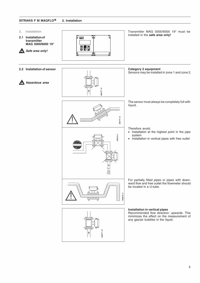
Category 2 equipmentSensors may be installed in zone 1 and zone 2.
2.2 Installation of sensor
Transmitter MAG 5000/6000 19" must beinstalled in the safe area only!
2.1 Installation oftransmitterMAG 5000/6000 19"
Safe area only!
Hazardous area
The sensor must always be completely full withliquid.
Therefore avoid:• Installation at the highest point in the pipe
system• Installation in vertical pipes with free outlet
For partially filled pipes or pipes with down-ward flow and free outlet the flowmeter shouldbe located in a U-tube.
Installation in vertical pipesRecommended flow direction: upwards. Thisminimizes the effect on the measurement ofany gas/air bubbles in the liquid.

6
SITRANS F M MAGFLO®®®®®
Installation in horizontal pipesThe sensor must be mounted as shown in theupper figure. Do not mount the sensor as shownin the lower figure. This will position the elec-trodes at the top where there is possibility for airbubbles and at the bottom where there is pos-sibility for mud, sludge, sand etc.If using empty pipe detection the sensor can betilted 45°, as shown in the upper figure.
Measuring abrasive liquids and liquids con-taining particlesRecommended installation is in a vertical/in-clined pipe to minimize the wear and depositsin the sensor.
Inlet and outlet conditionsTo achieve accurate flow measurement it isessential to have straight lengths of inlet andoutlet pipes and a certain distance betweenpumps and valves.It is also important to centre the flowmeter inrelation to pipe flanges and gaskets.
2.2 Installation of sensor(continued)
Installation in large pipesThe flowmeter can be installed between tworeducers (e.g. DIN 28545). Assuming that at 8°the following pressure drop curve applies. Thecurves are applicable to water.
Example:A flow velocity of 3 m/s (V) in a sensor with adiameter reduction from DN 100 to DN 80(d1/d2 = 0.8) gives a pressure drop of 2.9 mbar.
2. Installation
7
SITRANS F M MAGFLO®®®®® 2. Installation
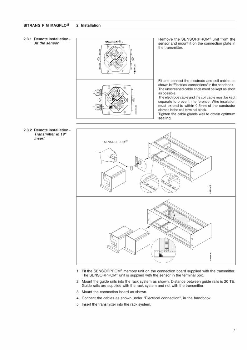
2.3.1 Remote installation -At the sensor
Fit and connect the electrode and coil cables asshown in “Electrical connections” in the handbook.The unscreened cable ends must be kept as shortas possible.The electrode cable and the coil cable must be keptseparate to prevent interference. Wire insulationmust extend to within 0,5mm of the conductorclamps in the coil terminal block.Tighten the cable glands well to obtain optimumsealing.
Remove the SENSORPROM® unit from thesensor and mount it on the connection plate inthe transmitter.
2.3.2 Remote installation -Transmitter in 19"insert
1. Fit the SENSORPROM® memory unit on the connection board supplied with the transmitter.The SENSORPROM® unit is supplied with the sensor in the terminal box.
2. Mount the guide rails into the rack system as shown. Distance between guide rails is 20 TE.Guide rails are supplied with the rack system and not with the transmitter.
3. Mount the connection board as shown.
4. Connect the cables as shown under "Electrical connection", in the handbook.
5. Insert the transmitter into the rack system.
8
SITRANS F M MAGFLO®®®®® 2. Installation
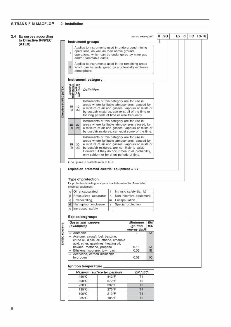
2.4 Ex survey accordingto Directive 94/9/EC(ATEX)
Applies to instruments used in underground miningoperations, as well as their above groundoperations, which can be endangered by mine gasand/or flammable dusts.
Instrument groups
Applies to instruments used in the remaining areaswhich can be endangered by a potentially explosiveatmosphere.
Instruments of this category are for use inareas where ignitable atmospheres, caused bya mixture of air and gasses, vapours or mists orby dust/air mixtures, can exist all of the time orfor long periods of time or else frequently.
Instruments of this category are for use inareas where ignitable atmospheres caused, bya mixture of air and gasses, vapours or mists orby dust/air mixtures, can exist some of the time.
Instruments of this category are for use inareas where ignitable atmospheres, caused bya mixture of air and gasses, vapours or mists orby dust/air mixtures, are not likely to exist.However, if they do occur then in all probability,only seldom or for short periods of time.
Instrument category
(The figures in brackets refer to IEC)
Explosion protected electrial equipment = Ex
as an example: II 2G Ex d IIC T3-T6
Type of protectionEx protection labelling in square brackets refers to "Associatedelectrical equipment"
o Oil encapsulated i Intrinsic safety (ia, ib)p Pressurized apparatus n Non-incentive equipmentq Powder filling m Encapsulationd Flameproof enclosure s Special protectione Increased safety
Explosion groups
Gases and vapours Minimum EN/(examples) ignition IEC
energy [mJ]• Ammonia - IIA• Acetone, aircraft fuel, benzine,
crude oil, diesel oil, ethane, ethanoicacid, ether, gasolines, heating oil,hexane, methane, propane 0.18 IIA
• Ethylene, isoprene, town gas 0.06 IIB• Acetylene, carbon disulphide,
hydrogen 0.02 IIC
Ignition temperature
Maximum surface temperature EN / IEC450°C 842°F T1300°C 572°F T2200°C 392°F T3135°C 275°F T4100°C 212°F T585°C 185°F T6
I
II
EN
/IEC
600
79-1
0D
irec
tive
94/
9/E
C (A
TE
X)
Definition
1G(0)
Labe
lling
wit
h g
ases
Labe
lling
with
dus
ts
1D(20)
2G(1)
2D(21)
3G(2)
3D(22)

9
SITRANS F M MAGFLO®®®®®
2.6 Device identificationexamples (MAG 1100Ex labels shown)
2. Installation
Can only be installed in safe area!
Specifications:Supply: 115-230 V or 24 V
2.5 Overview andintrinsically safe data
MAG 5000/600019" IP 20 & IP 65
All MAG 1100 Ex and MAG 3100 Ex sensorshave the following ratings and input parameters:
Category 2 equipmentSensors may be installed in zone 1 and zone 2.
MAG 1100 Ex &MAG 3100 Ex
MAG barriers ia electrodeUo 9.3 VIo 40 mAPo 0.4 WLo 23 mHCo 500 nF
Terminals 85-86 82-83MAG sensor coil electrodeUi 30/70 Vpk 30 VIi 130 mA 50 mAPi - 0.5 WLi - 2 μHCi - 50 nF
IS data transmitter
Ambient temperature: −20 to 50°CEnclosure: IP 20 or IP 65
Terminals 82-83
����������
����������
Sensors intrinsically safe data
10
SITRANS F M MAGFLO®®®®® 2. Installation
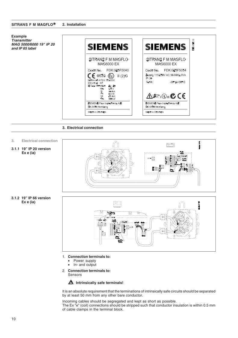
ExampleTransmitterMAG 5000/6000 19" IP 20and IP 65 label
It is an absolute requirement that the terminations of intrinsically safe circuits should be separatedby at least 50 mm from any other bare conductor.
Incoming cables should be segregated and kept as short as possible.The Ex "e" (coil) connections should be stripped such that conductor insulation is within 0.5 mmof cable clamps in the terminal block.
1. Connection terminals to:• Power supply• In- and output
2. Connection terminals to:Sensors
Intrinsically safe terminals!
3. Electrical connection
3. Electrical connection
3.1.1 19” IP 20 versionEx e (ia)
3.1.2 19” IP 66 versionEx e (ia)
11
SITRANS F M MAGFLO®®®®®
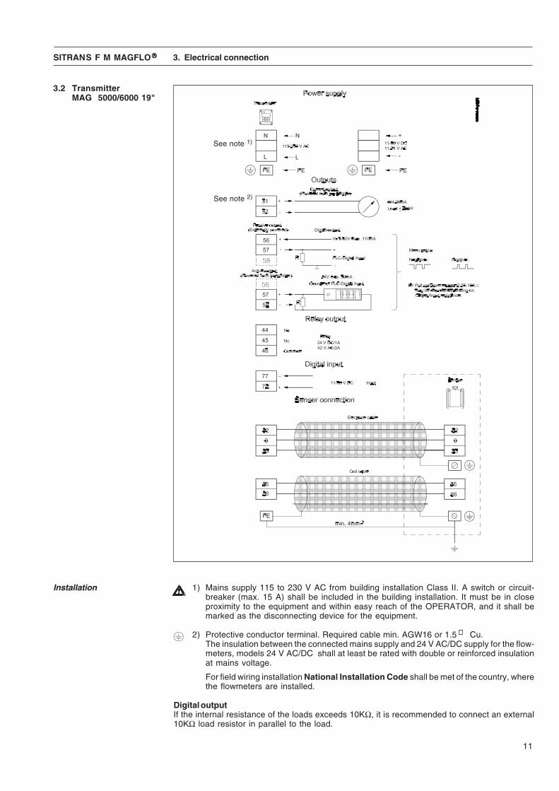
3.2 TransmitterMAG 5000/6000 19"
Installation 1) Mains supply 115 to 230 V AC from building installation Class II. A switch or circuit-breaker (max. 15 A) shall be included in the building installation. It must be in closeproximity to the equipment and within easy reach of the OPERATOR, and it shall bemarked as the disconnecting device for the equipment.
2) Protective conductor terminal. Required cable min. AGW16 or 1.5 Cu.The insulation between the connected mains supply and 24 V AC/DC supply for the flow-meters, models 24 V AC/DC shall at least be rated with double or reinforced insulationat mains voltage.
For field wiring installation National Installation Code shall be met of the country, wherethe flowmeters are installed.
Digital outputIf the internal resistance of the loads exceeds 10KΩ, it is recommended to connect an external10KΩ load resistor in parallel to the load.
3. Electrical connection
See note 1)
See note 2)
12
SITRANS F M MAGFLO®®®®®
4. Technical data
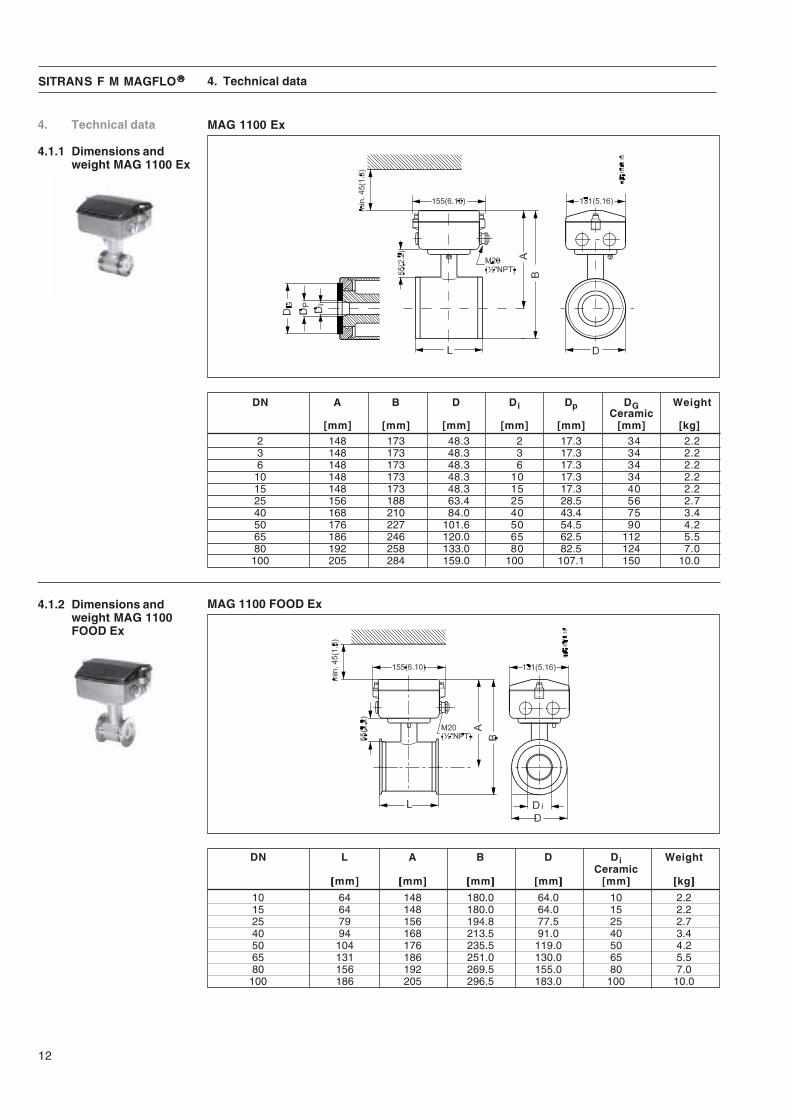
4.1.1 Dimensions andweight MAG 1100 Ex
DN A B D Di Dp DG WeightCeramic
[mm] [mm] [mm] [mm] [mm] [mm] [kg]2 148 173 48.3 2 17.3 34 2.23 148 173 48.3 3 17.3 34 2.26 148 173 48.3 6 17.3 34 2.2
10 148 173 48.3 10 17.3 34 2.215 148 173 48.3 15 17.3 40 2.225 156 188 63.4 25 28.5 56 2.740 168 210 84.0 40 43.4 75 3.450 176 227 101.6 50 54.5 90 4.265 186 246 120.0 65 62.5 112 5.580 192 258 133.0 80 82.5 124 7.0100 205 284 159.0 100 107.1 150 10.0
MAG 1100 Ex
4. Technical data
4.1.2 Dimensions andweight MAG 1100FOOD Ex
MAG 1100 FOOD Ex
DN L A B D Di WeightCeramic
[[[[[mm]]]]] [[[[[mm]]]]] [[[[[mm]]]]] [[[[[mm]]]]] [[[[[mm]]]]] [[[[[kg]]]]]10 64 148 180.0 64.0 10 2.215 64 148 180.0 64.0 15 2.225 79 156 194.8 77.5 25 2.740 94 168 213.5 91.0 40 3.450 104 176 235.5 119.0 50 4.265 131 186 251.0 130.0 65 5.580 156 192 269.5 155.0 80 7.0
100 186 205 296.5 183.0 100 10.0

13
SITRANS F M MAGFLO®®®®®
4.1.3 Sensor MAG 1100 Ex Version MAG 1100 Ex MAG 1100 HT Ex (High temperature)Measuring principle Electromagnetic induction Electromagnetic inductionExcitation frequency DN 2...65 (1/12“ … 2½”): 12.5 Hz DN 15...50 (1“ … 2”): 12.5 Hz
DN 80, 100 (3”, 4”): 6.25 Hz DN 80, 100 (3”, 4”): 6.25 HzProcess connectionNominal sizeMAG 1100 (Ceramic) DN 2…DN 100 (1/12"…4") DN 15…DN 100 (½”…4")Mating flanges EN 1092-1 (DIN 2501), ANSI B16.5 EN 1092-1 (DIN 2501), ANSI B16.5
class 150 and 300 or equivalent class 150 and 300 or equivalentOption:DN 2...10 (1/12”...3/8”):G½”/NPT ½” pipe connection adapters
Rated operatingconditionsAmbient conditionsAmbient temperature• Sensor -20…+60°C (-4…+140°F) -20…+60°C (-4…+140°F)1)
Temperature of medium• MAG 1100 (Ceramic) -20…+150°C (-4…+300°F) -20…+180°C (-4…+356°F)Temperature shock• MAG 1100 (Ceramic)Duration ≤ 1 min,followed by 10 min rest DN 2, 3 (1/12”, 1/8”) No limitations
DN 6, 10, 15, 25: Max. ΔT ≤ 80°C/min DN 15, 25: Max. ΔT ≤ 80°C/min(¼”, 3/8”, ½”, 1”: Max. ΔT ≤ 80 K/min) (½”, 1”: Max. ΔT ≤ 80 K/min)DN 40, 50, 65: Max. ΔT ≤ 70°C/min DN 40, 50: Max. ΔT ≤ 70°C/min(1½”, 2”, 2½”: Max. ΔT ≤ 70 K/min) (1½”, 2”: Max. ΔT ≤ 70 K/min)DN 80, 100: Max. ΔT ≤ 60°C/min DN 80, 100: Max. ΔT ≤ 60°C/min(3”, 4”: Max. ΔT ≤ 60 K/min) (3”, 4”: Max. ΔT ≤ 60 K/min)
Operating pressure• MAG 1100 (Ceramic) DN 2...65: 40 bar DN 15...50: 40 bar
(1/12”…2½”: 580 psi) (½”…2”: 580 psi)DN 80: 37.5 bar (3”: 540 psi) DN 80: 37.5 bar (3”: 540 psi)DN 100: 30 bar (4”: 435 psi) DN 100: 30 bar (4”: 435 psi)Vacuum: 1x10⁻⁶ bar (1.5x10⁻⁵ psi) Vacuum: 1x10⁻⁶ bar (1.5x10⁻⁵ psi)
Mechanical load 18 ... 1000 Hz random in x, y z, 18 ... 1000 Hz random in x, y z,directions for 2 hours according directions for 2 hours accordingto EN 60068-2-36 to EN 60068-2-36Sensor: 3.17 grms Sensor: 3.17 grms
Enclosure ratingStandard IP67 to EN 60529 (NEMA 4X/6), IP67 to EN 60529 (NEMA 4X/6),
1 mH2O for 30 min 1 mH2O for 30 minEMC 89/336EEC 89/336EECDesignWeight See dimensional drawings See dimensional drawingsMaterialEnclosure -MAG 1100 Stainless steel AISI 316L (1.4404) Stainless steel AISI 316L (1.4404)Terminal box
Stainless steel AISI 316 (1.4436) Stainless steel AISI 316 (1.4436)Fixing studs Stainless steel AISI 304 (1.4301), Stainless steel AISI 304 (1.4301),
Number and size to EN 1092-1:2001 Number and size to EN 1092-1:2001Gaskets EPDM (max. 150°C, PN 40 Graphite (max. 200°C, PN 40- Standard (max. 300°F, 600 psi) (max. 390°F, 600 psi)- Option Graphite (max. 200°C, PN 40
(max. 390°F, 600 psi)PTFE (max. 130°C, PN 25(max. 270°F, 300 psi)
Pipe connection adapters: - Stainless steel, AISI 316DN 2, 3, 6 and 10 - Hastelloy(1/12“, 1/8“, ¼”, 3/8”) - PVDF
4. Technical data
1) Up to medium temperature of 150ºC (300ºF). For medium temperature of 150 to 180ºC (300 to 356ºF) -20 to +50ºC (-4 to +122ºF)

14
SITRANS F M MAGFLO®®®®®
Version MAG 1100 Ex MAG 1100 HT Ex (High temperature)Liner• MAG 1100 (Ceramic) DN 2, 3 (1/12“, 1/8“): Zirconium DN 15...100 (½“... 4“): Aluminium
oxide (ZrO2) (ceramic) oxide Al2O3
DN 6 ... 100 (¼“ ... 4“): Aluminiumoxide Al2O3
Electrodes• MAG 1100 (Ceramic) DN 10 ...100 (3/8" ... 4") : Platinum Platinum with gold / Titanium
with gold / Titanium brazing alloy brazing alloyDN 2 ... 6 (1/12“ ... ¼”): Platinium
Cable entries Remote installation 2 x M20 Remote installation 2 x M20Certificates andapprovalsConforms to PED – 97/23EC PED – 97/23ECEx approvals• MAG 1100 (Ceramic)ATEX sensor ATEX 2G D sensor ATEX 2G D sensor
Ex d e ia IIB T3 - T6 Ex d e ia IIB T3 - T6
4.1.3 Sensor MAG 1100 Ex(continued)
4. Technical data
15
SITRANS F M MAGFLO®®®®®
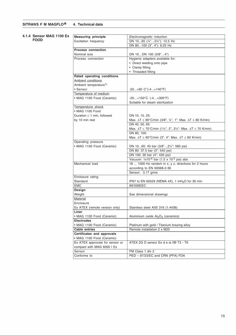
Measuring principle Electromagnetic inductionExcitation frequency DN 10...65 (¼“…2½”): 12.5 Hz
DN 80...100 (3”, 4”): 6.25 HzProcess connectionNominal size DN 10…DN 100 (3/8"…4")Process connection Hygienic adapters available for:
• Direct welding onto pipe• Clamp fitting• Threaded fitting
Rated operating conditionsAmbient conditionsAmbient temperature1)
• Sensor -20...+60 C°(-4...+140°F)Temperature of medium• MAG 1100 Food (Ceramic) -20…+150°C (-4…+300°F)
Suitable for steam sterilizationTemperature shock• MAG 1100 FoodDuration ≤ 1 min, followed DN 10, 15, 25:by 10 min rest Max. ΔT ≤ 80°C/min (3/8”, ½”, 1”: Max. ΔT ≤ 80 K/min)
DN 40, 50, 65:Max. ΔT ≤ 70°C/min (1½”, 2”, 2½”: Max. ΔT ≤ 70 K/min)DN 80, 100:Max. ΔT ≤ 60°C/min (3”, 4”: Max. ΔT ≤ 60 K/min)
Operating pressure• MAG 1100 Food (Ceramic) DN 10...65: 40 bar (3/8”…2½”: 580 psi)
DN 80: 37.5 bar (3”: 540 psi)DN 100: 30 bar (4”: 435 psi)Vacuum: 1x10⁻⁶ bar (1.5 x 10⁻⁵ psi) abs
Mechanical load 18 ... 1000 Hz random in x, y z, directions for 2 hoursaccording to EN 60068-2-36Sensor: 3.17 grms
Enclosure ratingStandard IP67 to EN 60529 (NEMA 4X), 1 mH2O for 30 minEMC 89/336EECDesignWeight See dimensional drawingsMaterialEnclosureEx ATEX (remote version only) Stainless steel AISI 316 (1.4436)Liner• MAG 1100 Food (Ceramic) Aluminium oxide Al2O3 (ceramics)Electrodes• MAG 1100 Food (Ceramic) Platinum with gold / Titanium brazing alloyCable entries Remote installation 2 x M20Certificates and approvals• MAG 1100 Food (Ceramic)Ex ATEX approvals for sensor or ATEX 2G D sensor Ex d e ia IIB T3 - T6compact with MAG 6000 I ExSensor FM Class 1 div 2Conforms to PED – 97/23/EC and CRN (PFA) FDA
4.1.4 Sensor MAG 1100 ExFOOD
4. Technical data
16
SITRANS F M MAGFLO®®®®®
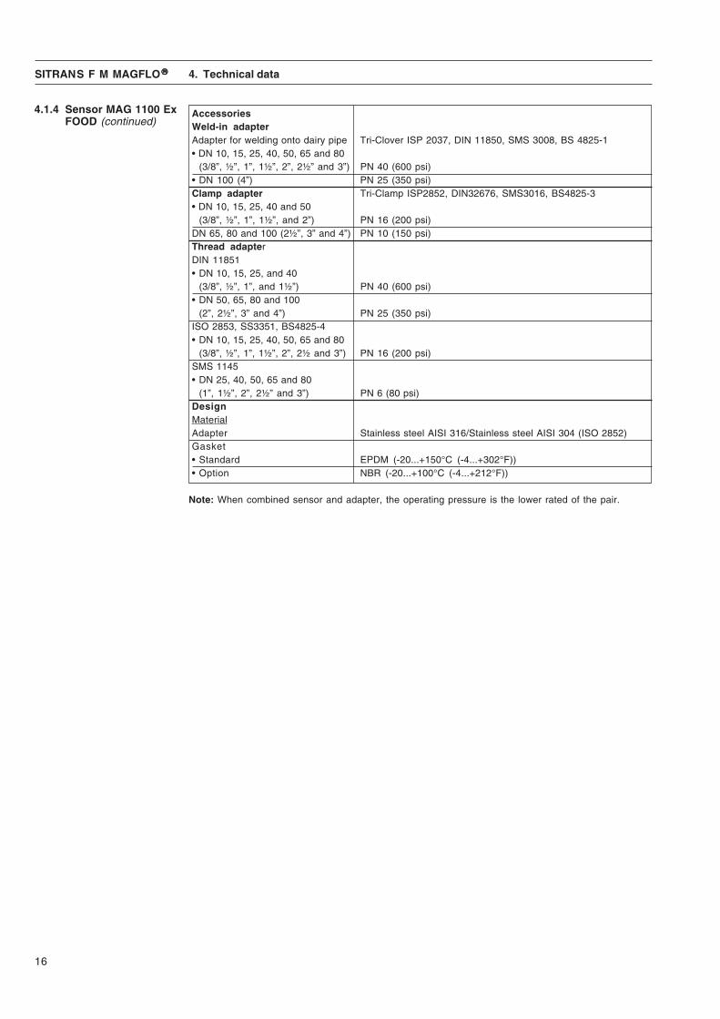
AccessoriesWeld-in adapterAdapter for welding onto dairy pipe Tri-Clover ISP 2037, DIN 11850, SMS 3008, BS 4825-1• DN 10, 15, 25, 40, 50, 65 and 80
(3/8”, ½”, 1”, 1½”, 2”, 2½” and 3”) PN 40 (600 psi)• DN 100 (4”) PN 25 (350 psi)Clamp adapter Tri-Clamp ISP2852, DIN32676, SMS3016, BS4825-3• DN 10, 15, 25, 40 and 50
(3/8”, ½”, 1”, 1½”, and 2”) PN 16 (200 psi)DN 65, 80 and 100 (2½”, 3” and 4”) PN 10 (150 psi)Thread adapterDIN 11851• DN 10, 15, 25, and 40
(3/8”, ½”, 1”, and 1½”) PN 40 (600 psi)• DN 50, 65, 80 and 100
(2”, 2½”, 3” and 4”) PN 25 (350 psi)ISO 2853, SS3351, BS4825-4• DN 10, 15, 25, 40, 50, 65 and 80
(3/8”, ½”, 1”, 1½”, 2”, 2½ and 3”) PN 16 (200 psi)SMS 1145• DN 25, 40, 50, 65 and 80
(1”, 1½”, 2”, 2½” and 3”) PN 6 (80 psi)DesignMaterialAdapter Stainless steel AISI 316/Stainless steel AISI 304 (ISO 2852)Gasket• Standard EPDM (-20...+150°C (-4...+302°F))• Option NBR (-20...+100°C (-4...+212°F))
Note: When combined sensor and adapter, the operating pressure is the lower rated of the pair.
4. Technical data
4.1.4 Sensor MAG 1100 ExFOOD (continued)

17
SITRANS F M MAGFLO®®®®®
4.2.1 Dimensions andweight MAG 3100 Ex
MAG 3100 Ex
4. Technical data
A B D1 L1) AS AWWA TC 2) TE
2)
2129 E C-207AS 4087 Class
PN 6, PN 16/ PN PN PN PN Class Class PN 16, D10 PN 16 25 40 63 100 150 300 21, 35
non PED[mm] [inch] [mm] [mm] [mm] [mm] [mm] [mm] [mm] [mm] [mm] [mm] [mm] [mm] [mm] [mm] [mm] [kg]
15 ½ 174 59 104 - - - 200 - - 200 200 200 - - 6 425 1 174 59 104 - - - 200 - 260 200 200 200 - 1.2 6 540 1½ 184 82 124 - - - 200 - 280 200 200 200 - 1.2 6 850 2 192 72 139 - - - 200 276 300 200 200 200 - 1.2 6 965 2½ 199 72 154 200 200/- - 200 320 350 200 272 200 - 1.2 6 1180 3 209 72 174 200 200/- - 272 323 340 272 272 2004) - 1.2 6 12
100 4 229 85 214 250 250/- - 250 380 400 250 310 250 - 1.2 6 16125 5 242 85 239 250 250/- - 250 420 450 250 335 250 - 1.2 6 19150 6 263 85 282 300 300/- - 300 415 450 300 300 300 - 1.2 6 27200 8 291 137 338 350 350/- 350 350 480 530 350 350 350 - 1.2 8 40250 10 319 157 393 450 450/- 450 450 550 620 450 450 450 - 1.2 8 60300 12 344 157 444 500 500/- 500 500 600 680 500 500 500 - 1.6 8 80350 14 349 270 451 550 550/- 550 550 - - 550 550 550 - 1.6 8 110400 16 374 270 502 600 600/- 600 600 - - 600 600 600 - 1.6 10 125450 18 405 310 563 600 600/- 600 600 - - 600 600 600 - 1.6 10 175500 20 430 350 614 600 600/- 625 680 - - 600 730 6005) - 1.6 10 200600 24 481 430 715 600 600/- 750 800 - - 600 860 6006) - 1.6 10 287700 28 531 500 816 700 875/700 - - - - - - 700 700 2.0 - 330750 30 558 556 869 - -/- - - - - - - 750 750 2.0 - 360800 32 593 560 927 800 1000/800 - - - - - - 800 800 2.0 - 450900 36 640 630 1032 900 1125/900 - - - - - - 900 900 2.0 - 5301000 40 691 670 1136 1000 1250/1000 - - - - - - 1000 1000 2.0 - 6601100 44 742 770 1238 - -/- - - - - - - 1100 1100 2.0 - 11401200 48 797 792 1348 1200 1500/1200 - - - - - - 1200 1200 2.0 - 11801400 56 912 1000 1675 1400 -/1400 - - - - - - - 1400 3.0 - 16001500 50 959 1020 1672 1500 -/1500 - - - - - - - 1500 3.0 - 24601600 64 1012 1130 1915 1600 -/1600 - - - - - - - 1600 3.0 - 21401800 72 1110 1250 1974 1800 -/1800 - - - - - - - 1800 3.0 - 29302000 78 1210 1375 2174 2000 -/2000 - - - - - - - 2000 3.0 - 3665
Weight3)
EN 1092-1-2001
Nominalsize
1) When earthing flanges are used, the thickness of the earthing flange must be added to the build-in length2) TC = Type C grounding ring3) Weights are approx. and for PN 164) PN 35 DN 80 = 272 mm5) PN 35 DN 500 = 680 mm6) PN 35 DN 600 = 750 mm
- Not availableD = Outside diameter of flange, see flange tables
ANSI 16.5

18
SITRANS F M MAGFLO®®®®® 4. Technical data
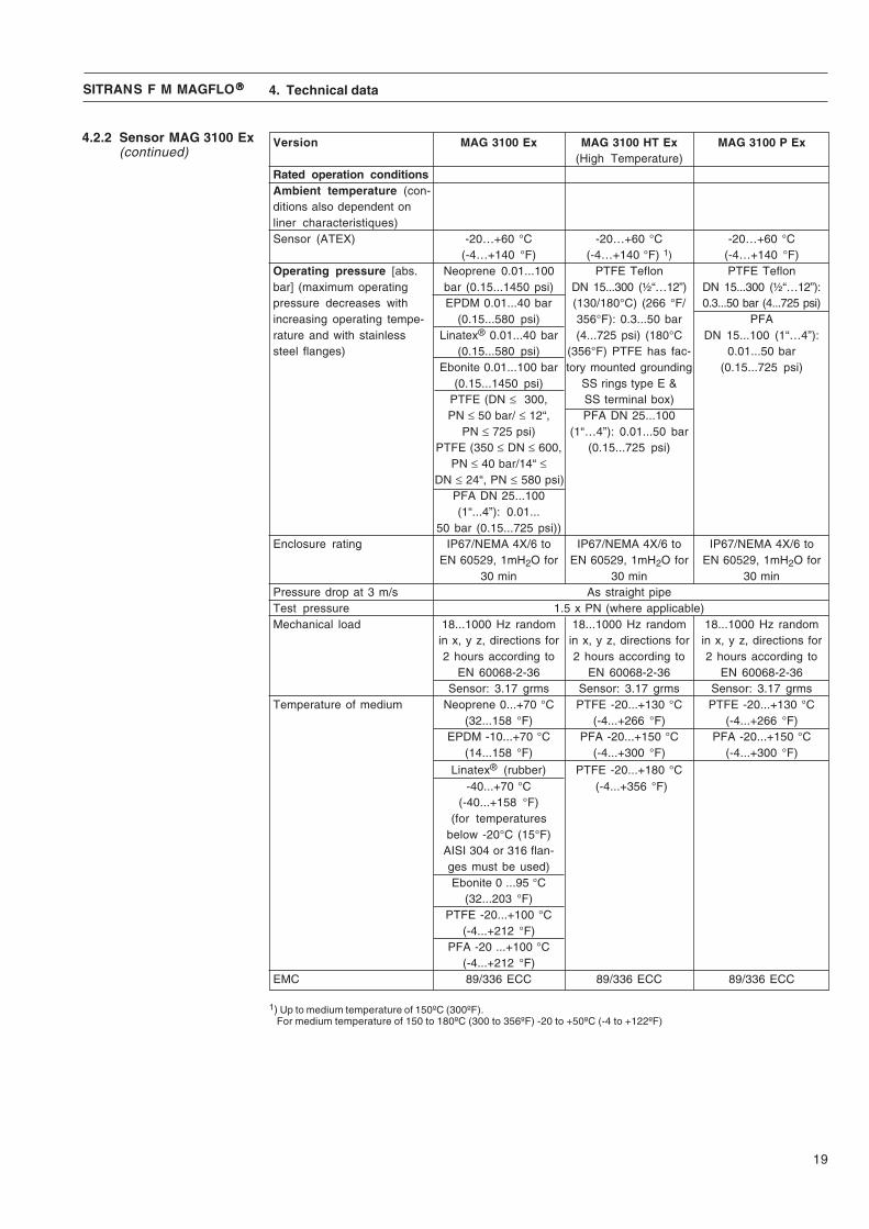
4.2.2 Sensor MAG 3100 Ex Version MAG 3100 Ex MAG 3100 HT Ex MAG 3100 P Ex(High Temperature)
Rated operation conditionsAmbient temperature (con-ditions also dependent onliner characteristiques)Sensor (ATEX) -20…+60 °C -20…+60 °C -20…+60 °C
(-4…+140 °F) (-4…+140 °F) 1) (-4…+140 °F)Operating pressure [abs. Neoprene 0.01...100 PTFE Teflon PTFE Teflonbar] (maximum operating bar (0.15...1450 psi) DN 15...300 (½“…12”) DN 15...300 (½“…12”):pressure decreases with EPDM 0.01...40 bar (130/180°C) (266 °F/ 0.3...50 bar (4...725 psi)increasing operating tempe- (0.15...580 psi) 356°F): 0.3...50 bar PFArature and with stainless Linatex® 0.01...40 bar (4...725 psi) (180°C DN 15...100 (1“…4”):steel flanges) (0.15...580 psi) (356°F) PTFE has fac- 0.01...50 bar
Ebonite 0.01...100 bar tory mounted grounding (0.15...725 psi)(0.15...1450 psi) SS rings type E &
PTFE (DN ≤ 300, SS terminal box)PN ≤ 50 bar/ ≤ 12“, PFA DN 25...100
PN ≤ 725 psi) (1“…4”): 0.01...50 barPTFE (350 ≤ DN ≤ 600, (0.15...725 psi)
PN ≤ 40 bar/14“ ≤DN ≤ 24“, PN ≤ 580 psi)
PFA DN 25...100(1“...4”): 0.01...
50 bar (0.15...725 psi))Enclosure rating IP67/NEMA 4X/6 to IP67/NEMA 4X/6 to IP67/NEMA 4X/6 to
EN 60529, 1mH2O for EN 60529, 1mH2O for EN 60529, 1mH2O for30 min 30 min 30 min
Pressure drop at 3 m/s As straight pipeTest pressure 1.5 x PN (where applicable)Mechanical load 18...1000 Hz random 18...1000 Hz random 18...1000 Hz random
in x, y z, directions for in x, y z, directions for in x, y z, directions for2 hours according to 2 hours according to 2 hours according to
EN 60068-2-36 EN 60068-2-36 EN 60068-2-36Sensor: 3.17 grms Sensor: 3.17 grms Sensor: 3.17 grms
Temperature of medium Neoprene 0...+70 °C PTFE -20...+130 °C PTFE -20...+130 °C(32...158 °F) (-4...+266 °F) (-4...+266 °F)
EPDM -10...+70 °C PFA -20...+150 °C PFA -20...+150 °C(14...158 °F) (-4...+300 °F) (-4...+300 °F)
Linatex® (rubber) PTFE -20...+180 °C-40...+70 °C (-4...+356 °F)
(-40...+158 °F)(for temperatures
below -20°C (15°F)AISI 304 or 316 flan-ges must be used)Ebonite 0 ...95 °C
(32...203 °F)PTFE -20...+100 °C
(-4...+212 °F)PFA -20 ...+100 °C
(-4...+212 °F)EMC 89/336 ECC 89/336 ECC 89/336 ECC
1) Up to medium temperature of 150ºC (300ºF). For medium temperature of 150 to 180ºC (300 to 356ºF) -20 to +50ºC (-4 to +122ºF)
19
SITRANS F M MAGFLO®®®®® 4. Technical data
4.2.2 Sensor MAG 3100 Ex(continued)
Version MAG 3100 Ex MAG 3100 HT Ex MAG 3100 P Ex(High Temperature)
Rated operation conditionsAmbient temperature (con-ditions also dependent onliner characteristiques)Sensor (ATEX) -20…+60 °C -20…+60 °C -20…+60 °C
(-4…+140 °F) (-4…+140 °F) 1) (-4…+140 °F)Operating pressure [abs. Neoprene 0.01...100 PTFE Teflon PTFE Teflonbar] (maximum operating bar (0.15...1450 psi) DN 15...300 (½“…12”) DN 15...300 (½“…12”):pressure decreases with EPDM 0.01...40 bar (130/180°C) (266 °F/ 0.3...50 bar (4...725 psi)increasing operating tempe- (0.15...580 psi) 356°F): 0.3...50 bar PFArature and with stainless Linatex® 0.01...40 bar (4...725 psi) (180°C DN 15...100 (1“…4”):steel flanges) (0.15...580 psi) (356°F) PTFE has fac- 0.01...50 bar
Ebonite 0.01...100 bar tory mounted grounding (0.15...725 psi)(0.15...1450 psi) SS rings type E &
PTFE (DN ≤ 300, SS terminal box)PN ≤ 50 bar/ ≤ 12“, PFA DN 25...100
PN ≤ 725 psi) (1“…4”): 0.01...50 barPTFE (350 ≤ DN ≤ 600, (0.15...725 psi)
PN ≤ 40 bar/14“ ≤DN ≤ 24“, PN ≤ 580 psi)
PFA DN 25...100(1“...4”): 0.01...
50 bar (0.15...725 psi))Enclosure rating IP67/NEMA 4X/6 to IP67/NEMA 4X/6 to IP67/NEMA 4X/6 to
EN 60529, 1mH2O for EN 60529, 1mH2O for EN 60529, 1mH2O for30 min 30 min 30 min
Pressure drop at 3 m/s As straight pipeTest pressure 1.5 x PN (where applicable)Mechanical load 18...1000 Hz random 18...1000 Hz random 18...1000 Hz random
in x, y z, directions for in x, y z, directions for in x, y z, directions for2 hours according to 2 hours according to 2 hours according to
EN 60068-2-36 EN 60068-2-36 EN 60068-2-36Sensor: 3.17 grms Sensor: 3.17 grms Sensor: 3.17 grms
Temperature of medium Neoprene 0...+70 °C PTFE -20...+130 °C PTFE -20...+130 °C(32...158 °F) (-4...+266 °F) (-4...+266 °F)
EPDM -10...+70 °C PFA -20...+150 °C PFA -20...+150 °C(14...158 °F) (-4...+300 °F) (-4...+300 °F)
Linatex® (rubber) PTFE -20...+180 °C-40...+70 °C (-4...+356 °F)
(-40...+158 °F)(for temperatures
below -20°C (15°F)AISI 304 or 316 flan-ges must be used)Ebonite 0 ...95 °C
(32...203 °F)PTFE -20...+100 °C
(-4...+212 °F)PFA -20 ...+100 °C
(-4...+212 °F)EMC 89/336 ECC 89/336 ECC 89/336 ECC
1) Up to medium temperature of 150ºC (300ºF). For medium temperature of 150 to 180ºC (300 to 356ºF) -20 to +50ºC (-4 to +122ºF)
20
SITRANS F M MAGFLO®®®®® 4. Technical data
4.2.2 Sensor MAG 3100 Ex(continued)
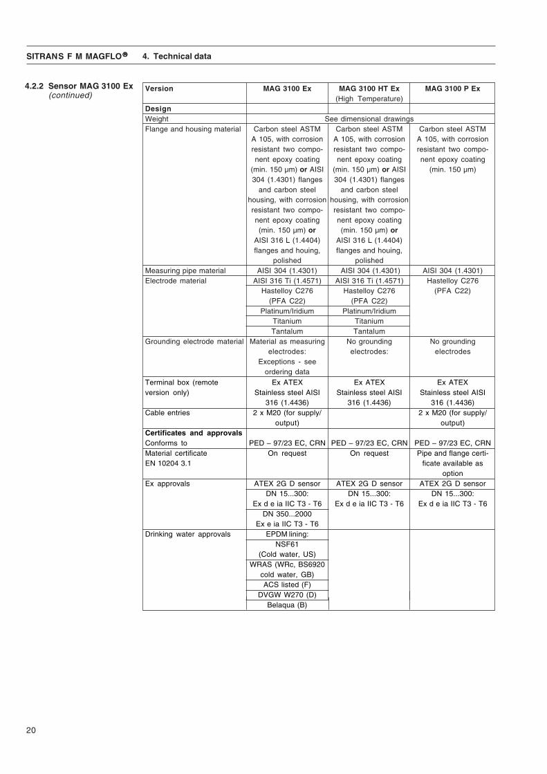
Version MAG 3100 Ex MAG 3100 HT Ex MAG 3100 P Ex(High Temperature)
DesignWeight See dimensional drawingsFlange and housing material Carbon steel ASTM Carbon steel ASTM Carbon steel ASTM
A 105, with corrosion A 105, with corrosion A 105, with corrosionresistant two compo- resistant two compo- resistant two compo-nent epoxy coating nent epoxy coating nent epoxy coating
(min. 150 μm) or AISI (min. 150 μm) or AISI (min. 150 μm)304 (1.4301) flanges 304 (1.4301) flanges
and carbon steel and carbon steelhousing, with corrosion housing, with corrosionresistant two compo- resistant two compo-nent epoxy coating nent epoxy coating(min. 150 μm) or (min. 150 μm) or
AISI 316 L (1.4404) AISI 316 L (1.4404)flanges and houing, flanges and houing,
polished polishedMeasuring pipe material AISI 304 (1.4301) AISI 304 (1.4301) AISI 304 (1.4301)Electrode material AISI 316 Ti (1.4571) AISI 316 Ti (1.4571) Hastelloy C276
Hastelloy C276 Hastelloy C276 (PFA C22)(PFA C22) (PFA C22)
Platinum/Iridium Platinum/IridiumTitanium TitaniumTantalum Tantalum
Grounding electrode material Material as measuring No grounding No groundingelectrodes: electrodes: electrodes
Exceptions - seeordering data
Terminal box (remote Ex ATEX Ex ATEX Ex ATEXversion only) Stainless steel AISI Stainless steel AISI Stainless steel AISI
316 (1.4436) 316 (1.4436) 316 (1.4436)Cable entries 2 x M20 (for supply/ 2 x M20 (for supply/
output) output)Certificates and approvalsConforms to PED – 97/23 EC, CRN PED – 97/23 EC, CRN PED – 97/23 EC, CRNMaterial certificate On request On request Pipe and flange certi-EN 10204 3.1 ficate available as
optionEx approvals ATEX 2G D sensor ATEX 2G D sensor ATEX 2G D sensor
DN 15...300: DN 15...300: DN 15...300:Ex d e ia IIC T3 - T6 Ex d e ia IIC T3 - T6 Ex d e ia IIC T3 - T6
DN 350...2000Ex e ia IIC T3 - T6
Drinking water approvals EPDM lining:NSF61
(Cold water, US)WRAS (WRc, BS6920
cold water, GB)ACS listed (F)
DVGW W270 (D)Belaqua (B)

21
SITRANS F M MAGFLO®®®®® 4. Technical data
Current outputCurrent 0-20 mA, 4-20 mA or 4-20 mA + alarmLoad < 800 ohmTime constant 0.1-30 s adjustable
Digital outputFrequency 0-10 kHz, 50% duty cycleTime constant 0.1-30 s adjustableActive 24 V DC, 30 mA, 1 KΩ ≤ Rload ≤ 10 KΩ, short-circuit-protectedPassive 3-30 V DC, max. 110 mA, 200 Ω ≤ Rload ≤ 10 KΩ
RelayTime constant Changeover relay, time constant same as current time constantLoad 42 V AC/2 A, 24 V DC/1A
Digital input 11-30 V DC, Ri = 4.4 KΩActivation time 50 msCurrent I11 V DC = 2.5 mA, I30 V DC = 7 mA
Functions Flow rate, 2 totalizers, low flow cut-off, empty pipe cut-off, flowdirection, error system, operating time, uni/bidirectional flow, limitswitches, pulse output, control for cleaning unit and batch
Galvanic isolation All inputs and outputs are galvanically isolatedCut-off
Low flow 0-9.9% of maximum flowTotalizer Two eight-digit counters for forward, net or reverse flowDisplay Background illumination with alphanumerical text, 3 × 20 characters
to indicate flow rate, totalized values, settings and faultsReverse flow indicated by negative sign
Time constant Time constant as current output time constantZero point adjustment AutomaticElectrode input impedance > 1 x 10¹⁴ ΩExcitation frequency Sensor size depending pulsating DC current (125 mA)Ambient temperature Display version during operation: −20 to +50°C
Blind version during operation: −20 to +60°CDuring storage: −40 to +70°C (RH max. 95%)
CommunicationStandard Prepared for client mounted add-on modulesOptional HART, Profibus PA as add-on module
19" insertEnclosure material Standard 19" insert of aluminium/steel (DIN 41494)
Width: 21 TEHeight: 3 HE
Enclosure rating IP 20 to EN 60529 and DIN 40050Mechanical load Version: 1 G, 1-800 Hz sinusoidal in all directions to EN 60068-2-36
EMC performance EN 61326Supply voltage 115-230 V AC +10% to −15%, 50-60 Hz
11-30 V DC or 11-24 V ACPower consumption 230 V AC: 17 VA
24 V DC: 9 W, IN = 380 mA, IST = 8A (30 ms)12 V DC: 11 W, IN = 920 mA, IST = 4A (250 ms)
4.3 TransmitterMAG 5000/6000 19"Accuracy 0.5/0.25%
1) Special cable required in separate mounted installation
22
SITRANS F M MAGFLO®®®®® 4. Technical data
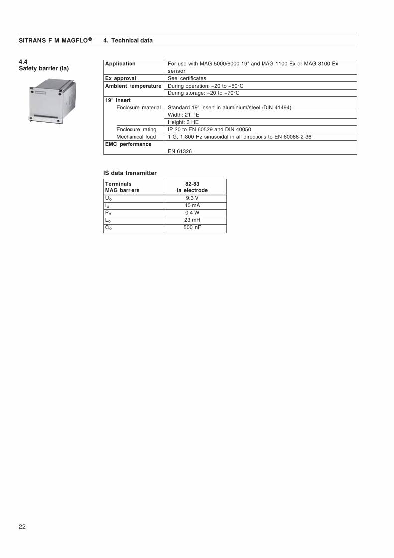
4.4Safety barrier (ia)
Application For use with MAG 5000/6000 19" and MAG 1100 Ex or MAG 3100 Exsensor
Ex approval See certificatesAmbient temperature During operation: −20 to +50°C
During storage: −20 to +70°C19" insert
Enclosure material Standard 19" insert in aluminium/steel (DIN 41494)Width: 21 TEHeight: 3 HE
Enclosure rating IP 20 to EN 60529 and DIN 40050Mechanical load 1 G, 1-800 Hz sinusoidal in all directions to EN 60068-2-36
EMC performanceEN 61326
Terminals 82-83MAG barriers ia electrodeUo 9.3 VIo 40 mAPo 0.4 WLo 23 mHCo 500 nF
IS data transmitter

23
SITRANS F M MAGFLO®®®®® 4. Technical data
4.5 Output characteris-tics MAG 5000/600019"
Output characteristics Bidirectional mode Unidirectional mode0-20 mA
4-20 mA
Frequency
Pulse output
RelayPower down Active
Error relay No error Error
Limit switch ordirection switch
Low flow Intermediate flow(Reverse flow)High flow High flow/(Forward flow) Low flow
Batch on digitaloutput
Batch on relay Hold Batch

24
SITRANS F M MAGFLO®®®®®
Communication mode Basic settings Operator active
Service mode Output Operator inactive
Operator menu External input
Product identity Sensor characteristics
Language mode Reset mode
5. Commissioning
5.1 Keypad and displaylayout
Keypad The keypad is used to set the flowmeter. The function of the keys is as follows:
TOP UP KEY This key (hold 2 sec.) is used to switch between operator menuand setup menu. In the transmitter setup menu, a short press willcause a return to the previous menu.
FORWARD KEY This key is used to step forward through the menus. It is the onlykey normally used by the operator.
BACKWARD KEY This key is used to step backward through the menus.
CHANGE KEY This key changes the settings or numerical values.
SELECT KEY This key selects the figures to be changed.
LOCK/UNLOCK KEY This key allows the operator to change settings and givesaccess to submenus.
Display The display is alphanumerical and indicates flow values, flowmeter settings and error messages.
The upper line is for primary flow readings and will always show either flow rate, totalizer 1 or totalizer2. The line is divided into 3 fields.
S: Sign fieldP: Primary field for numerical valueU: Unit field
The centre line is the title line (T) with individual information according to the selected operatoror setup menu.
The lowest line is the subtitle line (ST) which either will add information to the title line or keepindividual information independent of the title line.
F: The alarm field. Two flashing triangles will appear by a fault condition.
M: The mode field. The symbols indicate the following.
Ready for change Access to submenu
Value locked RESET MODE: Zero setting oftotalizers and initialization of setting
L: The lock field. Indicates the function of the lock key.
5. Commissioning
25
SITRANS F M MAGFLO®®®®®
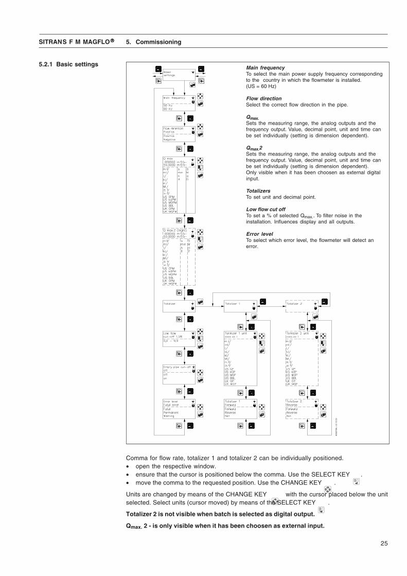
5.2.1 Basic settings
Comma for flow rate, totalizer 1 and totalizer 2 can be individually positioned.• open the respective window.• ensure that the cursor is positioned below the comma. Use the SELECT KEY .• move the comma to the requested position. Use the CHANGE KEY .
Units are changed by means of the CHANGE KEY with the cursor placed below the unitselected. Select units (cursor moved) by means of the SELECT KEY .
Totalizer 2 is not visible when batch is selected as digital output.
Qmax. 2 - is only visible when it has been choosen as external input.
Main frequencyTo select the main power supply frequency correspondingto the country in which the flowmeter is installed.(US = 60 Hz)
Flow directionSelect the correct flow direction in the pipe.
Qmax.Sets the measuring range, the analog outputs and thefrequency output. Value, decimal point, unit and time canbe set individually (setting is dimension dependent).
Qmax.2Sets the measuring range, the analog outputs and thefrequency output. Value, decimal point, unit and time canbe set individually (setting is dimension dependent).Only visible when it has been choosen as external digitalinput.
TotalizersTo set unit and decimal point.
Low flow cut offTo set a % of selected Qmax.. To filter noise in theinstallation. Influences display and all outputs.
Error levelTo select which error level, the flowmeter will detect anerror.
5. Commissioning

26
SITRANS F M MAGFLO®®®®®
Current outputOff
Current outputTime const.
Current outputCurrent outputUnidirectional
Alarm
UnidirectionalBidirectional
OnOff
5.2.2 Outputs
Digital outputFrequencyProportional to flowrate(Terminal 56, 57, 58)
The current output must be set off when not used.
Current outputProportional to flowrate(Terminal 31 and 32)
4 - 20 mA + alarm:Current output gives the following mA, depending on what is selected as error level in basic settings.Fatal: 1 mA, permanent: 2 mA, warning: 3 mA
Digital outputPulse/volume(Terminal 56, 57, 58)
5.2.3 External input
5. Commissioning
27
SITRANS F M MAGFLO®®®®®
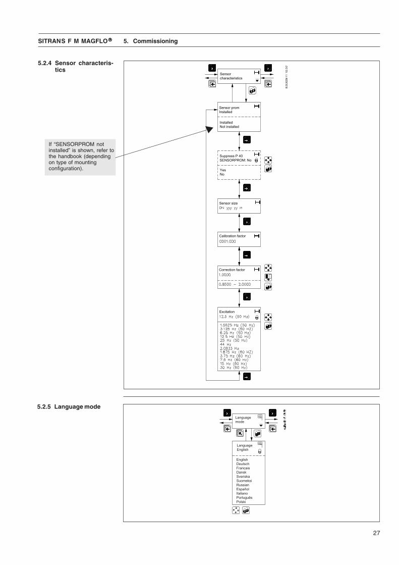
5.2.4 Sensor characteris-tics
If “SENSORPROM notinstalled” is shown, refer tothe handbook (dependingon type of mountingconfiguration).
5.2.5 Language mode
5. Commissioning
28
SITRANS F M MAGFLO®®®®®
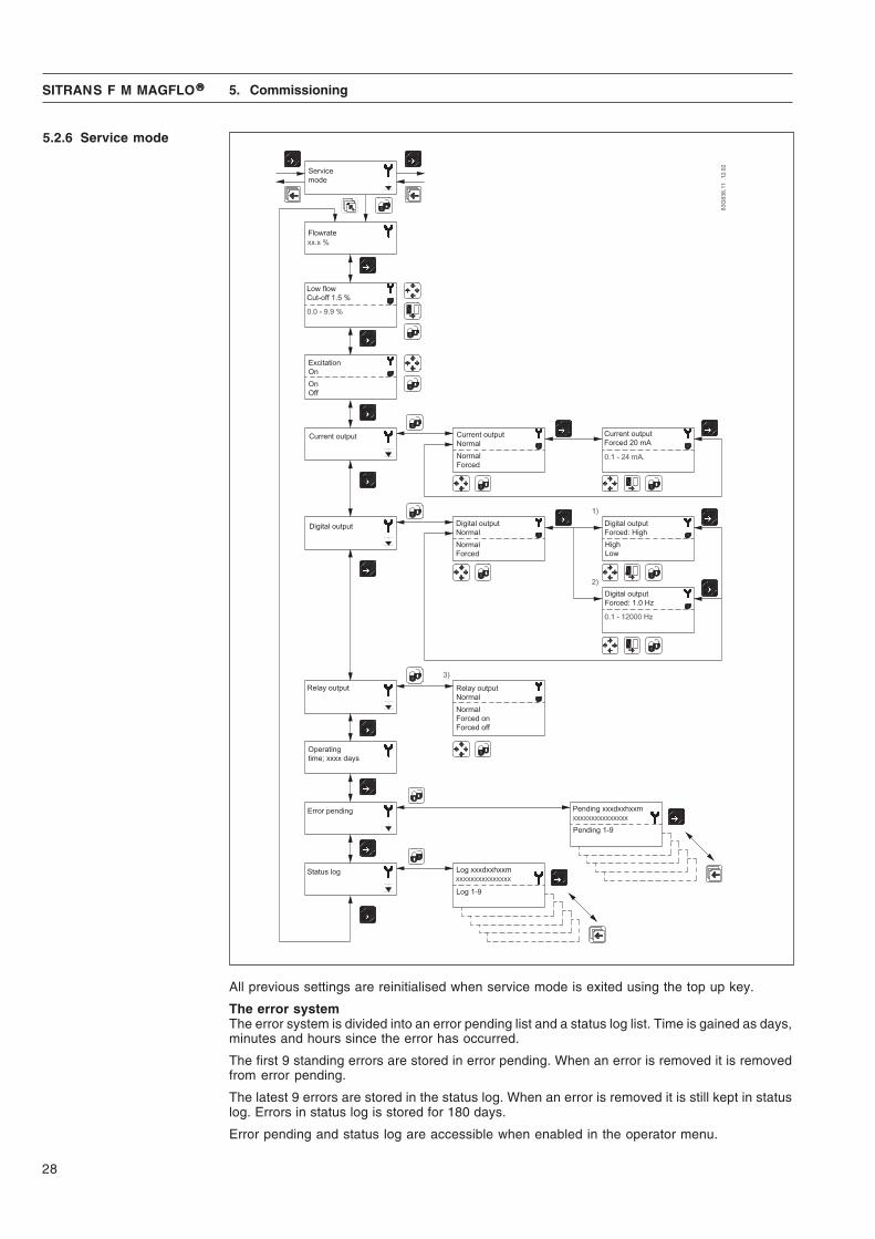
5.2.6 Service mode
All previous settings are reinitialised when service mode is exited using the top up key.
The error systemThe error system is divided into an error pending list and a status log list. Time is gained as days,minutes and hours since the error has occurred.
The first 9 standing errors are stored in error pending. When an error is removed it is removedfrom error pending.
The latest 9 errors are stored in the status log. When an error is removed it is still kept in statuslog. Errors in status log is stored for 180 days.
Error pending and status log are accessible when enabled in the operator menu.
5. Commissioning

29
SITRANS F M MAGFLO®®®®®
Power on transmitter,display light on
YES
NO
NO
Check cables/connectionsCheck connection boardCheck pins in transmittermultiplug - OK
Correct fault
YES
NO
Outputreadings OK
transmitterdefective
YES Display defectChange display
Output and displayreadings OK ?
NO
NO
Check cables/connectionsCheck connection boardCheck pins in transmittermultiplug - OK
Correct fault
Error triangles flashing
NO
YESCheck error table
Transmitter OK -Check settings/applicationCheck installation/sensor/earthing connection etc.
YES
YES
Often problems with unstable/wrong measurements occur due to insufficient/wrong earthing orpotential equalization. Please check this connection. If OK, the SITRANS F M MAGFLO transmit-ter can be checked as described in the handbook.
When checking SITRANS F M MAGFLO installations for malfunction the easiest method tocheck the transmitter is to replace it with another MAG 5000/6000 transmitter with a similar powersupply.A replacement can easily be done as all settings are stored in and downloaded from theSENSORPROM unit - no extra settings need to be made.
If no spare transmitter is available - then check transmitter according to check table.
6. Service
6. Service
6.1 Transmitter checklist
30
SITRANS F M MAGFLO®®®®®
7. Ordering
7. Ordering
Please use online PIA Selector to get latest updates.PIA selector link:
www.pia-selector.automation.siemens.com
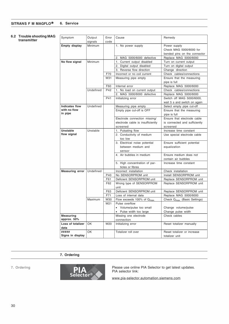
6.2 Trouble shooting MAGtransmitter
Symptom Output Error Cause Remedysignals code
Empty display Minimum 1. No power supply Power supplyCheck MAG 5000/6000 forbended pins on the connector
2. MAG 5000/6000 defective Replace MAG 5000/6000No flow signal Minimum 1. Current output disabled Turn on current output
2. Digital output disabled Turn on digital output3. Reverse flow direction Change direction
F70 Incorrect or no coil current Check cables/connectionsW31 Measuring pipe empty Ensure that the measuring
pipe is fullF60 Internal error Replace MAG 5000/6000
Undefined P42 1. No load on current output Check cables/connections2. MAG 5000/6000 defective Replace MAG 5000/6000
P41 Initializing error Switch off MAG 5000/6000,wait 5 s and switch on again
Indicates flow Undefined Measuring pipe empty Select empty pipe cut-offwith no flow Empty pipe cut-off is OFF Ensure that the measuringin pipe pipe is full
Electrode connection missing/ Ensure that electrode cableelectrode cable is insufficiently is connected and sufficientlyscreened screened
Unstable Unstable 1. Pulsating flow Increase time constantflow signal 2. Conductivity of medium Use special electrode cable
too low3. Electrical noise potential Ensure sufficient potential
between medium and equalizationsensor
4. Air bubbles in medium Ensure medium does notcontain air bubbles
5. High concentration of par- Increase time constantticles or fibres
Measuring error Undefined Incorrect installation Check installationP40 No SENSORPROM unit Install SENSORPROM unitF61 Deficient SENSORPROM unit Replace SENSORPROM unitF62 Wrong type of SENSORPROM Replace SENSORPROM unit
unitF63 Deficient SENSORPROM unit Replace SENSORPROM unitF71 Loss of internal data Replace MAG 5000/6000
Maximum W30 Flow exceeds 100% of Qmax. Check Qmax. (Basic Settings)W21 Pulse overflow
• Volume/pulse too small Change volume/pulse• Pulse width too large Change pulse width
Measuring Missing one electrode Check cablesapprox. 50% connectionLoss of totalizer OK W20 Initializing error Reset totalizer manuallydata##### OK Totalizer roll over Reset totalizer or increaseSigns in display totalizer unit
6. Service
31
SITRANS F M MAGFLO®®®®® 8. Certificates
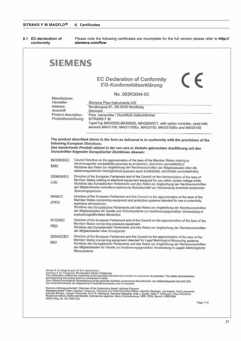
Please note the following certificates are incomplete for the full version please refer to http://siemens.com/flow
8.1 EC-declaration ofconformity
32
SITRANS F M MAGFLO®®®®® 8. Certificates

33
SITRANS F M MAGFLO®®®®® 8. Certificates

34
SITRANS F M MAGFLO®®®®®
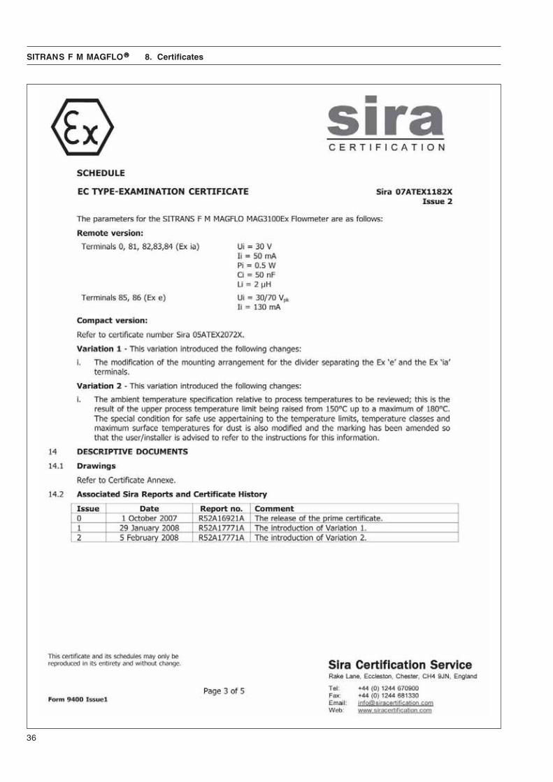
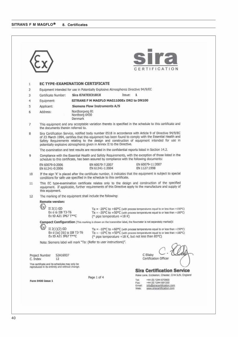
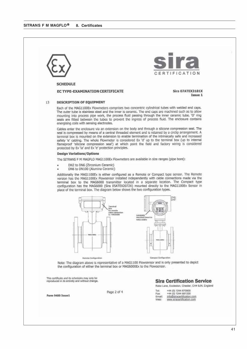
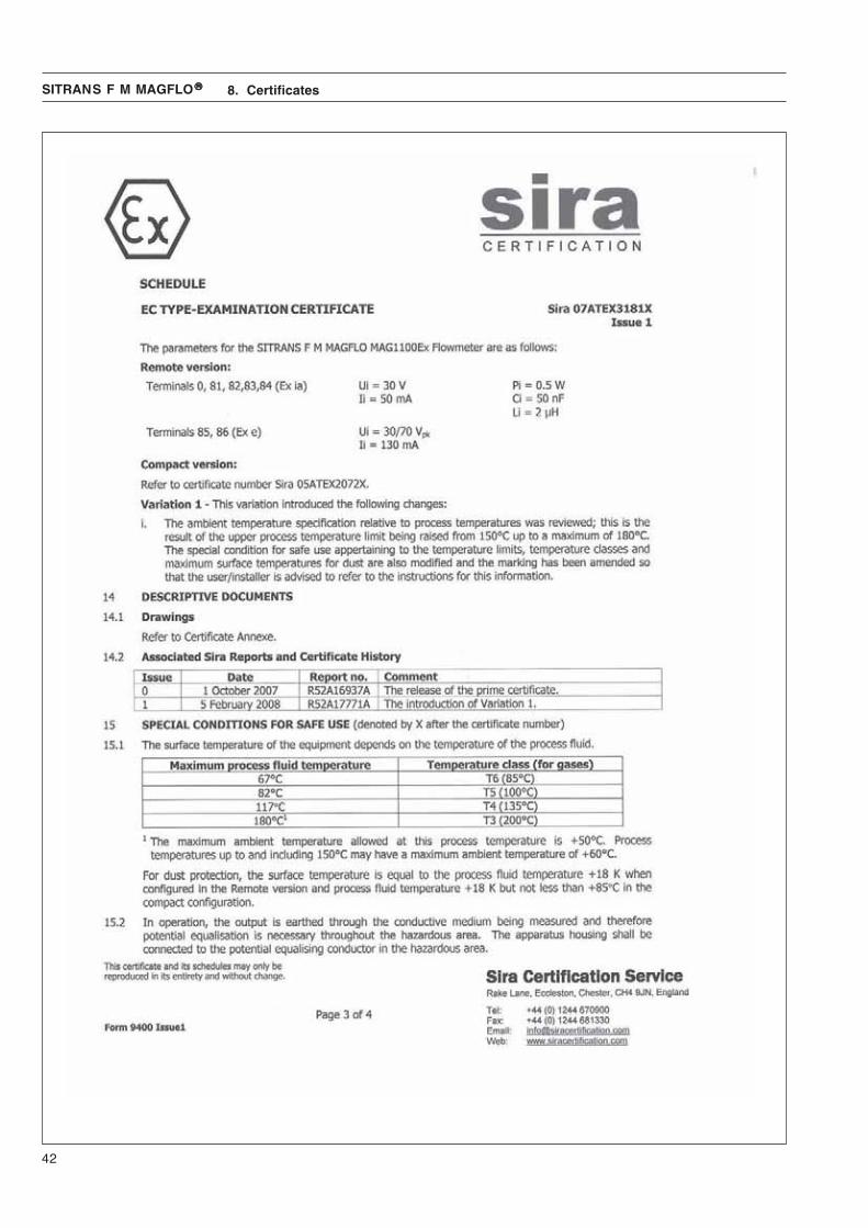
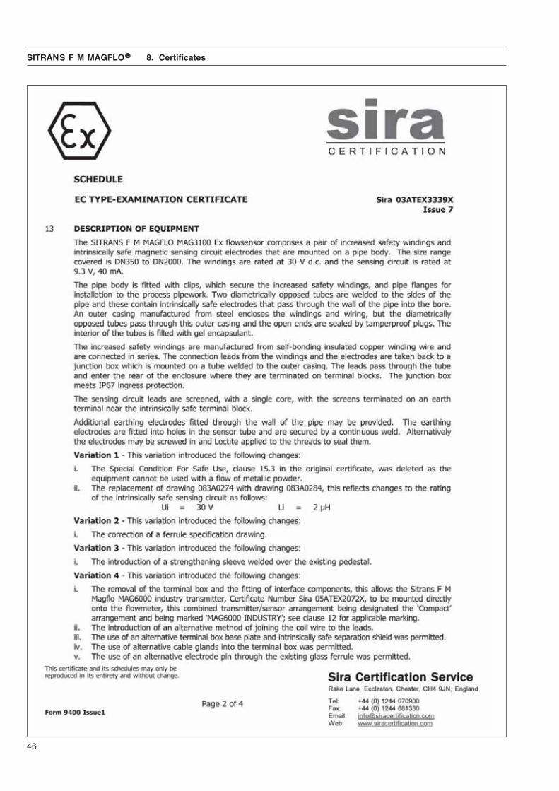
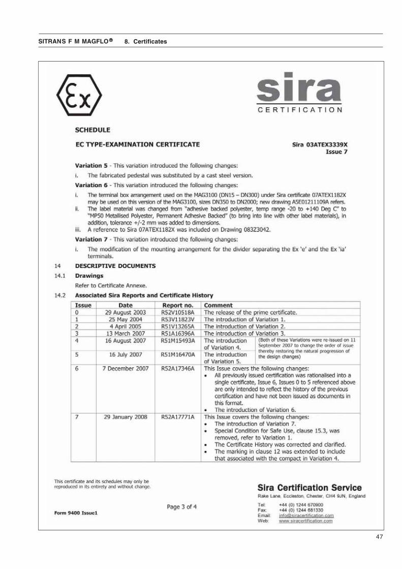
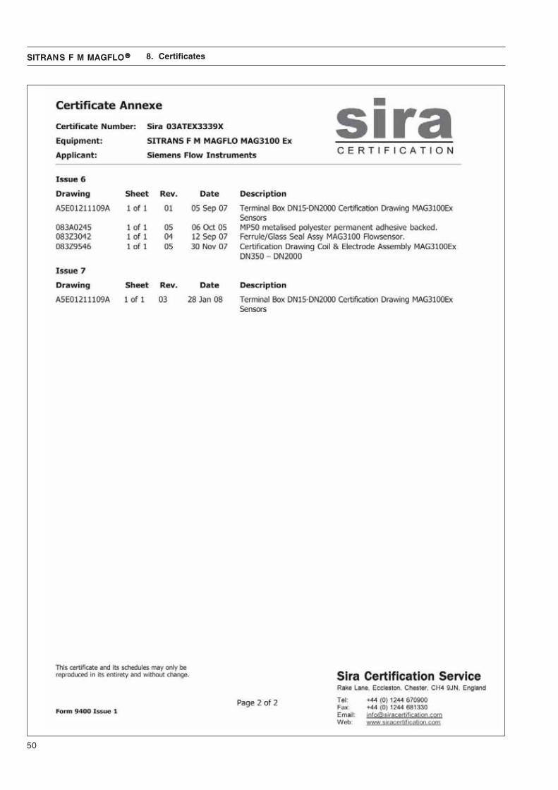
8.2 EC type examinationcertificate
Please note the following certificates are incomplete for the full version please refer to http://siemens.com/flow
8. Certificates

35
SITRANS F M MAGFLO®®®®® 8. Certificates
36
SITRANS F M MAGFLO®®®®® 8. Certificates

37
SITRANS F M MAGFLO®®®®® 8. Certificates

38
SITRANS F M MAGFLO®®®®® 8. Certificates

39
SITRANS F M MAGFLO®®®®®
40
SITRANS F M MAGFLO®®®®® 8. Certificates
41
SITRANS F M MAGFLO®®®®® 8. Certificates
42
SITRANS F M MAGFLO®®®®® 8. Certificates

43
SITRANS F M MAGFLO®®®®® 8. Certificates

44
SITRANS F M MAGFLO®®®®® 8. Certificates

45
SITRANS F M MAGFLO®®®®® 8. Certificates
46
SITRANS F M MAGFLO®®®®® 8. Certificates
47
SITRANS F M MAGFLO®®®®® 8. Certificates

48
SITRANS F M MAGFLO®®®®® 8. Certificates

49
SITRANS F M MAGFLO®®®®® 8. Certificates
50
SITRANS F M MAGFLO®®®®® 8. Certificates

51
SITRANS F M MAGFLO®®®®® 8. Certificates

52
SITRANS F M MAGFLO®®®®® 8. Certificates

53
SITRANS F M MAGFLO®®®®® 8. Certificates

Siemens A/S Flow InstrumentsNordborgvej 81DK-6430 Nordborg
Subject to change without prior noticeOrder No.: A5E02082880Lit. No.: SFIDK.PS.026.C4.02© Siemens AG 07.2010
For more information
www.siemens.com/flow
!A5E02082880!


![ADDIMAX CABLE GLANDS FOR INDUSTRIAL USE CABLE GLANDS Glands/Cable Glands.pdf · [ 2 ] CABLE GLANDS FOR INDUSTRIAL USE Single Compression A2 Type Weatherproof & Waterproof (IP66) Cable](https://img.dokumen.tips/doc/110x75/5abe4c4f7f8b9ac0598ceed5/addimax-cable-glands-for-industrial-use-cable-glandscable-glandspdf-2-cable.jpg)