Embed Size (px)
Citation preview

450H, 550H, 650HCrawler Dozer
*OMT182515*
OPERATOR'S MANUAL450H/550H/650H Crawler Dozers
OMT182515 ISSUE G3 (ENGLISH)
CALIFORNIAProposition 65 Warning
Diesel engine exhaust and some of its constituentsare known to the State of California to cause cancer,
birth defects, and other reproductive harm.
If this product contains a gasoline engine:
WARNING
The engine exhaust from this product containschemicals known to the State of California to causecancer, birth defects or other reproductive harm.
The State of California requires the above two warnings.
Additional Proposition 65 Warnings can be found in this manual.
Worldwide ConstructionAnd Forestry Division
LITHO IN U.S.A.

Introduction
OUO1043,0000469 -19-14JAN08-1/1
Foreword
READ THIS MANUAL carefully to learn how to operateand service your machine correctly. Failure to do socould result in personal injury or equipment damage.This manual and safety signs on your machine may alsobe available in other languages. (See your John Deeredealer to order.)
THIS MANUAL SHOULD BE CONSIDERED a permanentpart of your machine and should remain with the machinewhen you sell it.
MEASUREMENTS in this manual are given in bothmetric and customary U.S. unit equivalents. Use onlycorrect replacement parts and fasteners. Metric and inchfasteners may require a specific metric or inch wrench.
RIGHT-HAND AND LEFT-HAND sides are determined byfacing in the direction of forward travel.
WRITE PRODUCT IDENTIFICATION NUMBERS (P.I.N.)in the Machine Numbers section. Accurately record allthe numbers to help in tracing the machine should it be
stolen. Your dealer also needs these numbers when youorder parts. File the identification numbers in a secureplace off the machine.
WARRANTY is provided as part of John Deere's supportprogram for customers who operate and maintain theirequipment as described in this manual. The warranty isexplained on the warranty certificate which you shouldhave received from your dealer.
This warranty provides you the assurance that JohnDeere will back its products where defects appear withinthe warranty period. In some circumstances, John Deerealso provides field improvements, often without chargeto the customer, even if the product is out of warranty.Should the equipment be abused, or modified to changeits performance beyond the original factory specifications,the warranty will become void and field improvementsmay be denied. Setting fuel delivery above specificationsor otherwise overpowering machines will result in suchaction.
070813
PN=2

Introduction
Continued on next page DX,EMISSIONS,EPA -19-12DEC12-1/2
EPA Non-road Emissions Control Warranty Statement—Compression Ignition
DXLOGOV1 —UN—28APR09
U.S. AND CANADA EMISSION CONTROL WARRANTY STATEMENTYOUR WARRANTY RIGHTS AND OBLIGATIONS
To determine if the John Deere engine qualifies for the additional warranties set forth below, look for the "Emissions Control Information" labellocated on the engine. If the engine is operated in the United States or Canada and the Emissions Control information label states: "This enginecomplies with US EPA regulations for nonroad and stationary diesel engines”, or “This engine conforms to US EPA nonroad compression-ignitionregulations”, refer to the "U.S. and Canada Emission Control Warranty Statement." If the engine is operated in California, and the label states: "Thisengine complies with US EPA and CARB regulations for nonroad diesel engines”, or “This engine conforms to US EPA and California nonroadcompression-ignition emission regulations”, also refer to the "California Emission Control Warranty Statement.”
Warranties stated on this certificate refer only to emissions-related parts and components of your engine. The complete engine warranty, lessemissions-related parts and components, is provided separately. If you have any questions about your warranty rights and responsibilities,you should contact John Deere at 1-319-292-5400.
JOHN DEERE'S WARRANTY RESPONSIBILITY
John Deere warrants to the ultimate purchaser and each subsequent purchaser that this off-road diesel engine including all parts of itsemission-control system was designed, built and equipped so as to conform at the time of the sale with Section 213 of the Clean Air Act and is freefrom defects in materials and workmanship which would cause the engine to fail to conform with applicable US EPA regulations for a period of fiveyears from the date the engine is placed into service or 3,000 hours of operation, whichever first occurs.
Where a warrantable condition exists, John Deere will repair or replace, as it elects, any part or component with a defect in materials orworkmanship that would increase the engine’s emissions of any regulated pollutant within the stated warranty period at no cost to you, includingexpenses related to diagnosing and repairing or replacing emission-related parts. Warranty coverage is subject to the limitations and exclusionsset forth herein. Emission- related components include engine parts developed to control emissions related to the following:Air-Induction SystemFuel SystemIgnition SystemExhaust Gas Recirculation Systems
Aftertreatment DevicesCrankcase Ventilation ValvesSensorsEngine Electronic Control Units
EMISSION WARRANTY EXCLUSIONS
John Deere may deny warranty claims for malfunctions or failures caused by:
• Non-performance of maintenance requirements listed in the Operator’s Manual• The use of the engine/equipment in a manner for which it was not designed• Abuse, neglect, improper maintenance or unapproved modifications or alterations• Accidents for which it does not have responsibility or by acts of God
The off-road diesel engine is designed to operate on diesel fuel as specified in the Fuels, Lubricants and Coolants section in the Operators Manual.Use of any other fuel can harm the emissions control system of the engine/equipment and is not approved for use.
To the extent permitted by law John Deere is not liable for damage to other engine components caused by a failure of an emission-relatedpart, unless otherwise covered by standard warranty.
THIS WARRANTY IS EXPRESSLY IN LIEU OF ANY OTHER WARRANTIES, EXPRESS OR IMPLIED, INCLUDING ANY WARRANTYOF MERCHANTABILITY OR FITNESS FOR A PARTICULAR PURPOSE. REMEDIES UNDER THIS WARRANTY ARE LIMITED TO THEPROVISIONS OF MATERIAL AND SERVICES AS SPECIFIED HEREIN. WHERE PERMITTED BY LAW, NEITHER JOHN DEERE NOR ANYAUTHORIZED JOHN DEERE ENGINE DISTRIBUTOR, DEALER, OR REPAIR FACILITY OR ANY COMPANY AFFILIATED WITH JOHNDEERE WILL BE LIABLE FOR INCIDENTAL OR CONSEQUENTIAL DAMAGES.
Emission_CI_EPA (18Dec09)
070813
PN=3

Introduction
DX,EMISSIONS,EPA -19-12DEC12-2/2
TS1721
—UN—17DEC12
070813
PN=4
Introduction
Continued on next page DX,EMISSIONS,CARB -19-12DEC12-1/4
CARB Non-road Emissions Control Warranty Statement—Compression Ignition
DXLOGOV1 —UN—28APR09
CALIFORNIA EMISSIONS CONTROL WARRANTY STATEMENTYOUR WARRANTY RIGHTS AND OBLIGATIONS
To determine if the John Deere engine qualifies for the additional warranties set forth below, look for the “Emission Control Information” label locatedon the engine. If the engine is operated in the United States or Canada and the engine label states: “This engine complies with US EPA regulationsfor nonroad and stationary diesel engines”, or “This engine complies with US EPA regulations for stationary emergency diesel engines”, refer to the“U.S. and Canada Emission Control Warranty Statement.” If the engine is operated in California, and the engine label states: “This engine complieswith US EPA and CARB regulations for nonroad diesel engines” also refer to the “California Emissions Control Warranty Statement.”
Warranties stated on this certificate refer only to emissions-related parts and components of your engine. The complete engine warranty, lessemission-related parts and components, is provided separately. If you have any questions about your warranty rights and responsibilities,you should contact John Deere at 1-319-292-5400.
CALIFORNIA EMISSIONS CONTROL WARRANTY STATEMENT:
The California Air Resources Board (CARB) is pleased to explain the emission-control system warranty on 2013 through 2015 off-road dieselengines. In California, new off-road engines must be designed, built and equipped to meet the State’s stringent anti-smog standards. John Deeremust warrant the emission control system on your engine for the periods of time listed below provided there has been no abuse, neglect orimproper maintenance of your engine.
Your emission control system may include parts such as the fuel injection system and the air induction system. Also included may be hoses, belts,connectors and other emission-related assemblies.
John Deere warrants to the ultimate purchaser and each subsequent purchaser that this off-road diesel engine was designed, built, and equippedso as to conform at the time of sale with all applicable regulations adopted by CARB and is free from defects in materials and workmanship whichwould cause the failure of a warranted part to be identical in all material respects to the part as described in John Deere's application for certificationfor a period of five years from the date the engine is delivered to an ultimate purchaser or 3,000 hours of operation, whichever occurs first for allengines rated at 19 kW and greater. In the absence of a device to measure hours of use, the engine shall be warranted for a period of five years.
EMISSIONS WARRANTY EXCLUSIONS:
John Deere may deny warranty claims for failures caused by the use of an add-on or modified part which has not been exempted by the CARB. Amodified part is an aftermarket part intended to replace an original emission-related part which is not functionally identical in all respects and whichin any way affects emissions. An add-on part is any aftermarket part which is not a modified part or a replacement part.
In no event will John Deere, any authorized engine distributor, dealer, or repair facility, or any company affiliated with John Deere be liablefor incidental or consequential damage.
070813
PN=5

Introduction
Continued on next page DX,EMISSIONS,CARB -19-12DEC12-2/4
JOHN DEERE'S WARRANTY RESPONSIBILITY:
Where a warrantable condition exists, John Deere will repair or replace, as it elects, your off-road diesel engine at no cost to you, includingdiagnosis, parts or labor. Warranty coverage is subject to the limitations and exclusions set forth herein. The off-road diesel engine is warrantedfor a period of five years from the date the engine is delivered to an ultimate purchaser or 3,000 hours of operation, whichever occurs first.The following are emissions-related parts:
Air Induction System
• Intake manifold• Turbocharger• Charge air cooler
Fuel Metering system
• Fuel injection system
Exhaust Gas Recirculation
• EGR valve
Catalyst or Thermal Reactor Systems
• Catalytic converter• Exhaust manifold
Emission control labels
Particulate Controls
• Any device used to capture particulateemissions• Any device used in the regeneration of thecapturing system• Enclosures and manifolding• Smoke Puff Limiters
Positive Crankcase Ventilation (PCV) System
• PCV valve• Oil filler cap
Advanced Oxides of Nitrogen (NOx) Controls
• NOx absorbers and catalysts
SCR systems and urea containers/dispensingsystems
Miscellaneous Items used in Above Systems
• Electronic control units, sensors, actuators,wiring harnesses, hoses, connectors, clamps,fittings, gasket, mounting hardware
Any warranted emissions-related part scheduled for replacement as required maintenance is warranted by John Deere for the period of time priorto the first scheduled replacement point for the part. Any warranted emissions-related part not scheduled for replacement as required maintenanceor scheduled only for regular inspection is warranted by John Deere for the stated warranty period.
OWNER'S WARRANTY RESPONSIBILITIES:
As the off-road diesel engine owner you are responsible for the performance of the required maintenance listed in your Operator’s Manual. JohnDeere recommends that the owner retain all receipts covering maintenance on the off-road diesel engine, but John Deere cannot deny warrantysolely for the lack of receipts or for the owner’s failure to ensure the performance of all scheduled maintenance. However, as the off-road dieselengine owner, you should be aware that John Deere may deny you warranty coverage if your off-road diesel engine or a part has failed due toabuse, neglect, improper maintenance or unapproved modifications.
The off-road diesel engine is designed to operate on diesel fuel as specified in the Fuels, Lubricants and Coolants section in the Operators Manual.Use of any other fuel may result in the engine no longer operating in compliance with applicable emissions requirements.
The owner is responsible for initiating the warranty process, and should present the machine to the nearest authorized John Deere dealer as soonas a problem is suspected. The warranty repairs should be completed by the authorized John Deere dealer as quickly as possible.
Emissions regulations require the customer to bring the unit to an authorized servicing dealer when warranty service is required. As a result, JohnDeere is NOT liable for travel or mileage on emissions warranty service calls.
Emission_CI_CARB (19Sep12)
070813
PN=6

Introduction
Continued on next page DX,EMISSIONS,CARB -19-12DEC12-3/4
TS1722
—UN—17DEC12
070813
PN=7

Introduction
DX,EMISSIONS,CARB -19-12DEC12-4/4
TS1723
—UN—17DEC12
070813
PN=8

Introduction
TX,II,FAX -19-10JUL01-1/1
Technical Information Feedback FormWe need your help to continually improve our technicalpublications. Please copy this page and FAX or mail yourcomments, ideas and improvements.SEND TO: John Deere Dubuque Works
18600 South John Deere RoadAttn: Publications, Dept. 324Dubuque, IA 52004-0538USA
FAX NUMBER: 1-563-589-5800 (USA)
Publication Number:
Page Number:
Ideas, Comments:
Name:
Phone:
Email Address:
THANK YOU!
070813
PN=9

Introduction
070813
PN=10

Contents
Page
Safety—Safety FeaturesSafety Features .................................................1-1-1
Safety—General PrecautionsRecognize Safety Information ...........................1-2-1Follow Safety Instructions..................................1-2-1Operate Only If Qualified ...................................1-2-1Wear Protective Equipment...............................1-2-2Avoid Unauthorized Machine Modifications.......1-2-2Inspect Machine ................................................1-2-2Stay Clear of Moving Parts................................1-2-2Avoid High-Pressure Fluids ...............................1-2-3Beware of Exhaust Fumes ................................1-2-3Prevent Fires .....................................................1-2-4Prevent Battery Explosions ...............................1-2-4Handle Chemical Products Safely .....................1-2-4Dispose of Waste Properly ................................1-2-5Prepare for Emergencies...................................1-2-5Add Cab Guarding For Special Uses ................1-2-5
Safety—Operating PrecautionsStart Only From Operator's Seat .......................1-3-1Prevent Unintended Machine Movement ..........1-3-1Avoid Worksite Hazards ....................................1-3-1Keep Riders Off Machine ..................................1-3-2Avoid Backover Accidents .................................1-3-2Avoid Machine Tip Over ....................................1-3-3
Safety—Maintenance PrecautionsPark And Prepare For Service Safely................1-4-1Service Cooling System Safely .........................1-4-1Remove Paint Before Welding or Heating.........1-4-2Make Welding Repairs Safely ...........................1-4-2Drive Metal Pins Safely .....................................1-4-2
Safety—Safety SignsSafety Signs ......................................................1-5-1
Operation—Operator's StationInstrument Panel with Gauge
Package—If Equipped (Earlier Machines) ....2-1-1Instrument Panel Functions (Earlier
Machines)......................................................2-1-2Instrument Panel (Later Machines) ...................2-1-3Instrument Panel Functions (Later Machines)...2-1-4Transmission Controller Display Window ..........2-1-5
Page
Air Conditioning and Cab Heater—IfEquipped .......................................................2-1-8
Windshield Wiper and Washer Controls............2-1-8Windshield Washer Reservoir ...........................2-1-8Horn Switch .......................................................2-1-9Auxiliary Power Outlet—If Equipped .................2-1-9Side Windows—Secondary Exits ....................2-1-10Adjust Non-Suspension Seat...........................2-1-10Adjust Suspension Seat—If Equipped.............2-1-11Adjust Armrest .................................................2-1-11Seat Belt ..........................................................2-1-12
Operation—Operating The MachineInspect Machine Daily Before Starting ..............2-2-1Check Instruments Before Starting
(Earlier Machines) .........................................2-2-2Check Instruments Before Starting
(Later Machines) ...........................................2-2-3Starting the Engine (Earlier Machines)..............2-2-4Starting the Engine (Later Machines) ................2-2-6Starting Fluid (Cold Weather Start
Aid)—If Equipped ..........................................2-2-8Using Coolant Heater—If Equipped ..................2-2-9Operating Fuel-Fired Coolant
Heater—If Equipped....................................2-2-10Using Booster Batteries—12 Volt System .......2-2-17Engine Warm-Up .............................................2-2-17Cold Weather Warm-Up ..................................2-2-18Driving the Machine with Standard
FNR Lever (Earlier Machines).....................2-2-18Transmission Speed Reverse Ratio
Knob—If Equipped ......................................2-2-19FNR with Transmission Speed In
Grip—If Equipped........................................2-2-20Driving the Machine using FNR with
Transmission Speed In Grip—IfEquipped (Earlier Machines).......................2-2-21
Driving the Machine using FNR withTransmission Speed In Grip—IfEquipped (Later Machines) .........................2-2-22
Steering the Machine.......................................2-2-23Steering using FNR with Transmission
Speed In Grip Lever—If Equipped ..............2-2-24Using Engine Speed Control Lever .................2-2-25Travel Speed Using FNR Transmission
Speed In the Grip—If Equipped ..................2-2-25
Continued on next page
Original Instructions. All information, illustrations and specifications in thismanual are based on the latest information available at the time of publication.
The right is reserved to make changes at any time without notice.COPYRIGHT © 2013DEERE & COMPANY
Moline, IllinoisAll rights reserved.
A John Deere ILLUSTRUCTION ® ManualPrevious Editions
Copyright © 1998,1999,2000, 2001, 2002, 2003, 2004, 2005, 2009
i 070813
PN=1

Contents
Page
Foot Pedals .....................................................2-2-26Using Park Lock Lever ....................................2-2-26Stopping the Machine......................................2-2-26Parking the Machine........................................2-2-27Blade Pitch Operation......................................2-2-28Operating Blade...............................................2-2-29Tilting Blade.....................................................2-2-29Angling Blade ..................................................2-2-30Operating Winch—If Equipped........................2-2-31Fasten Cable toWinch Drum—4000S Series ..2-2-32Winch Free Spool Drag Adjustment ................2-2-35Avoid Track Damage .......................................2-2-35Loading Machine on a Trailer ..........................2-2-36Releasing the Park Brake to Tow the
Machine.......................................................2-2-37
Maintenance—MachineDiesel Fuel.........................................................3-1-1Low Sulfur Diesel Fuel Conditioner ...................3-1-1Testing Diesel Fuel ............................................3-1-1Handling and Storing Diesel Fuel ......................3-1-2Alternative and Synthetic Lubricants .................3-1-2Diesel Engine Break-In Oil ................................3-1-3Diesel Engine Oil ...............................................3-1-4Track Rollers, Front Idler and Carrier
Roller Oil .......................................................3-1-4Transmission and Hydraulic Oil .........................3-1-5Final Drive Oil ....................................................3-1-6Winch Oil ...........................................................3-1-7Grease...............................................................3-1-7Heavy Duty Diesel Engine Coolant ...................3-1-8
Maintenance—Periodic MaintenanceService Your Machine at Specified Intervals .....3-2-1Check the Hour Meter Regularly .......................3-2-1Prepare Machine for Maintenance ....................3-2-1Fuel Tank...........................................................3-2-2Maintenance and Repair Record
Keeping System............................................3-2-2Oilscan Plus ®, Coolscan Plus ®,
Dieselscan and 3-Way Coolant Test Kit ........3-2-3Service Intervals ................................................3-2-4
Maintenance—As RequiredInspect Serpentine Belt .....................................3-3-1Check Track Sag ...............................................3-3-2Adjust Track Sag ...............................................3-3-3Operating in Mud or Snow.................................3-3-5Check Blade Ball and Socket Joint....................3-3-5
Maintenance—Every 10 Hours or DailyCheck Coolant Level .........................................3-4-1Check Engine Oil Level .....................................3-4-2Drain Water Separator Sediment ......................3-4-2Check Hydraulic Oil Level .................................3-4-3Check Transmission Oil Level ...........................3-4-3
Page
Clean Dust Unloader Valve ...............................3-4-4Lubricate Dozer Linkage and Blade Socket ......3-4-4Check Winch Oil—If Equipped ..........................3-4-5
Maintenance—After 100 HoursChange Engine Break-In Oil and Filter..............3-5-1
Maintenance—Every 250 HoursDrain Final Fuel Filter Sediment ........................3-6-1Check Final Drives Oil Level .............................3-6-1Change Engine Oil and Filter (450H,
550H Earlier Machines and All 650HMachines)......................................................3-6-1
Maintenance—Every 500 HoursChange Engine Oil and Filter (450H,
550H Later Machines)...................................3-7-1Check Air Intake Hose.......................................3-7-1Replace Final Fuel Filter....................................3-7-2Replace Primary Fuel Filter ...............................3-7-3Check Coolant Conditioner in Radiator .............3-7-4Check Battery Electrolyte Level and Terminals ..3-7-5Replace Winch Oil Filter—If Equipped ..............3-7-7
Maintenance—Every 1000 HoursClean Engine Crankcase Ventilation Tube ........3-8-1Change Final Drives Oil.....................................3-8-1Replace Air Cleaner Elements ..........................3-8-2Replace Dust Unloader Valve............................3-8-3Drain and Refill Winch Oil and Replace
Filter—If Equipped ........................................3-8-4Clean or Replace Winch Hydraulic
Breather Filter—If Equipped..........................3-8-5
Maintenance—Every 2000 HoursAdjust Engine Valve Lash (Clearance) ..............3-9-1Change Hydraulic Oil and Filter.........................3-9-1Change Transmission Oil and Filter ..................3-9-2
Miscellaneous—MachineDrain the Cooling System..................................4-1-1Fill the Cooling System......................................4-1-2Clean the Engine Air Precleaner Screen...........4-1-2Replace Engine Vibration Damper ....................4-1-2Do Not Service or Adjust Injection
Nozzles or Injection Pump ............................4-1-3C-Frame Ball / Blade Socket Joint Adjustment ..4-1-3Cleaning Dusty Primary Element.......................4-1-4Precautions for Alternator and Regulator ..........4-1-4Handling, Checking and Servicing
Batteries Carefully.........................................4-1-5Replacing Batteries ...........................................4-1-6Removing Batteries ...........................................4-1-7Fuse Specifications for ROPS Units
(Earlier Machines) .........................................4-1-8
Continued on next page
ii 070813
PN=2

Contents
Page
Fuse Specifications for ROPS Units(Later Machines) .........................................4-1-10
Fuse Specifications for Cab Units—IfEquipped (Earlier Machines).......................4-1-12
Fuse Specifications for Cab Units—IfEquipped (Later Machines) .........................4-1-14
Drain Fuel Tank Sump.....................................4-1-15Cleaning Fresh Cab Air Filter—If Equipped ....4-1-16Cleaning Cab Air Recirculation
Filter—If Equipped ......................................4-1-16Check Air Conditioner Refrigerant
Level—If Equipped......................................4-1-17Track Sag General Information .......................4-1-18Adding Oil to the Roller....................................4-1-19Do Not Service Control Valves and Cylinders ..4-1-19Adjusting Engine Speed Control Lever
Tension (Earlier Machines)..........................4-1-19Checking Neutral Start System .......................4-1-20Keep ROPS Installed Properly ........................4-1-20Checking Track Shoe Cap Screw Torque........4-1-21Hardware Torque Specifications......................4-1-21Unified Inch Bolt and Screw Torque Values.....4-1-22Metric Bolt and Screw Torque Values..............4-1-23
Miscellaneous—Operational CheckoutOperational Checkout........................................4-2-1
Miscellaneous—TroubleshootingTroubleshooting Procedure ...............................4-3-1Engine ...............................................................4-3-2Electrical System...............................................4-3-5Hydraulic System...............................................4-3-7Hydrostatic Transmission ..................................4-3-8Gauges and Indicators ......................................4-3-9Transmission Controller Service Codes ..........4-3-10
Miscellaneous—StoragePrepare Machine for Storage ............................4-4-1Avoid Track Damage .........................................4-4-1
Miscellaneous—Machine NumbersGeneral..............................................................4-5-1Record Engine Serial Number...........................4-5-1Keep Machines Secure .....................................4-5-2Keep Proof of Ownership ..................................4-5-2
Miscellaneous—Specifications450H Crawler Dozer Dimensions ......................4-6-1450H Crawler Dozer Specifications...................4-6-2450H Crawler Dozer Weights ............................4-6-3450H-LT Crawler Dozer Dimensions .................4-6-4450H-LT Crawler Dozer Specifications..............4-6-5450H-LT Crawler Dozer Weights.......................4-6-6450H-LGP Crawler Dozer Dimensions..............4-6-7450H-LGP Crawler Dozer Specifications ..........4-6-8450H-LGP Crawler Dozer Weights....................4-6-9450H, 450H-LT and 450H-LGP Crawler
Dozer Drain and Refill Capacities .................4-6-9
Page
550H Crawler Dozer Dimensions ....................4-6-10550H Crawler Dozer Specifications.................4-6-11550H Crawler Dozer Weights ..........................4-6-12550H-LGP Crawler Dozer Dimensions............4-6-13550H-LGP Crawler Dozer Specifications ........4-6-14550H-LGP Crawler Dozer Weights..................4-6-15550H and 550H-LGP Crawler Dozer
Drain and Refill Capacities..........................4-6-15650H Crawler Dozer Dimensions ....................4-6-16650H Crawler Dozer Specifications.................4-6-17650H Crawler Dozer Weights ..........................4-6-18650H-LGP Crawler Dozer Dimensions............4-6-19650H-LGP Crawler Dozer Specifications ........4-6-20650H-LGP Crawler Dozer Weights..................4-6-21650H-XLT Crawler Dozer Dimensions.............4-6-22650H-XLT Crawler Dozer Specifications .........4-6-23650H-XLT Crawler Dozer Weights ..................4-6-24650H, 650H-LGP and 650H-XLT
Crawler Dozer Drain and Refill Capacities ..4-6-244000S Winch ...................................................4-6-24
iii 070813
PN=3

Contents
iv 070813
PN=4

Safety—Safety Features
HG31779,0000090 -19-03JUN02-1/1
Safety Features
T155521
1
23
4
5
6
7
8
9
1011
12
T155521—UN—19JU
N02
Please remember, the operator is the key topreventing accidents.
1. ROPS, FOPS, and OPS. Structures designed to helpprotect the operator are certified to ISO, SAE, andOSHA. Enclosures also deflect sun and rain.
2. Pressurized Cab. Positive pressure ventilationsystem circulates both outside and inside air throughfilters for a clean working environment. Built-indefroster vents directs air flow for effective windowdefogging/deicing.
3. Interior Rear View Mirror. Offers the operator a viewof activity behind him.
4. Park Lock Lever. When park lock lever is placedin “lock” position, the transmission shifts in neutral,the hydraulics are deactivated, and the park brake isengaged.
5. Handholds. Large conveniently placed handholdsmake it easy to enter or exit the operator's station.
6. Bypass Start Protection. Shielding over the startersolenoid helps prevent dangerous bypass starting.
7. Engine Fan Guard. A secondary fan guard insideengine compartment helps prevent contact withengine fan blades.
8. Steps. Wide skid-resistant steps help prevent slippingwhile getting in or out of the operator's station.
9. Neutral Start. Neutral start feature prevents theengine from being started unless transmission controlis in neutral.
10.Automatic Seatbelt Retractors.Seat belt retractorshelp keep belts clean and convenient to use.
11. Backup Alarm. Alerts bystanders when reverse traveldirection is selected by operator.
12.Operator Manual Holder. A sealed manual holderkeeps manual on machine clean and dry.
1-1-1 070813
PN=15

Safety—General Precautions
TX03679,00016CC -19-05FEB10-1/1
TX03679,00016F9 -19-12AUG03-1/1
TX03679,00016FA -19-03JAN07-1/1
Recognize Safety InformationThis is the safety alert symbol. When you see thissymbol on your machine or in this manual, be alertfor the potential of personal injury.
Follow the precautions and safe operating practiceshighlighted by this symbol.
A signal word — DANGER, WARNING, or CAUTION —is used with the safety alert symbol. DANGER identifiesthe most serious hazards.
On your machine, DANGER signs are red in color,WARNING signs are orange, and CAUTION signs areyellow. DANGER and WARNING signs are located nearspecific hazards. General precautions are on CAUTIONlabels.
T133555—UN—15APR13
T133588—19—28AUG00
Follow Safety InstructionsRead the safety messages in this manual and on themachine. Follow these warnings and instructions carefully.Review them frequently. Keep safety signs in goodcondition. Replace missing or damaged safety signs.Be sure new equipment componenets and repair partsinclude teh current safety signs. Replacement safetysigns are available from your John Deere dealer.
Be sure all operators of this machine understand everysafety message. Replace operator's manual and safetylabels immediately if missing or damaged.
T133556—UN—24AUG00
Operate Only If Qualified
Do not operate this machine unless the operator's manualhas been read carefully, and you have been qualified bysupervised training and instruction.
Operator should be familiar with the job site andsurroundings before operating. Try all controls and
machine functions with the machine in an open areabefore starting to work.
Know and observe all safety rules that may apply to everywork situation and work site.
1-2-1 070813
PN=16

Safety—General Precautions
TX03679,00016D0 -19-05MAY10-1/1
AM40430,0000084 -19-01OCT07-1/1
TX03679,0001734 -19-08JAN08-1/1
TX03679,00016D2 -19-08JAN08-1/1
Wear Protective EquipmentGuard against injury from flying pieces of metal or debris;wear goggles or safety glasses.
Wear close fitting clothing and safety equipmentappropriate to the job.
Prolonged exposure to loud noise can cause impairmentor loss of hearing. Wear suitable hearing protection suchas earmuffs or earplugs to protect against objectionableor uncomfortable loud noises.
TS206—UN—15APR13
Avoid Unauthorized Machine Modifications
John Deere recommends using only genuine John Deerereplacement parts to ensure machine performance.Never substitute genuine John Deere parts with alternateparts not intended for the application as these cancreate hazardous situations or hazardous performance.Non-John Deere Parts, or any damage or failures resultingfrom their use are not covered by any John Deere warranty.
Modifications of this machine, or addition of unapprovedproducts or attachments, may affect machine stabilityor reliability, and may create a hazard for the operator
or others near the machine. The installer of anymodification which may affect this machine is responsiblefor establishing that the modification does not adverselyaffect the machine or its performance. This applies to allaspects of the machine, including electronic controls.
Always contact an authorized dealer before makingmachine modifications that change the intended use,weight or balance of the machine, or that alter machinecontrols, performance or reliability.
Inspect MachineInspect machine carefully each day by walking around itbefore starting.
Keep all guards and shields in good condition and properlyinstalled. Fix damage and replace worn or broken partsimmediately. Pay special attention to hydraulic hoses andelectrical wiring.
T6607A
Q—UN—15APR13
Stay Clear of Moving PartsEntanglements in moving parts can cause serious injury.
Stop engine before examining, adjusting or maintainingany part of machine with moving parts.
Keep guards and shields in place. Replace any guardor shield that has been removed for access as soon asservice or repair is complete. T1
33592—UN—15APR13
1-2-2 070813
PN=17

Safety—General Precautions
TX03679,00016D3 -19-07SEP06-1/1
TX03679,00016D4 -19-23JUN08-1/1
Avoid High-Pressure FluidsThis machine uses a high-pressure hydraulic system.Escaping fluid under pressure can penetrate the skincausing serious injury.
Never search for leaks with your hands. Protect hands.Use a piece of cardboard to find location of escaping fluid.Stop engine and relieve pressure before disconnectinglines or working on hydraulic system.
If hydraulic fluid penetrates your skin, see a doctorimmediately. Injected fluid must be removedsurgically within hours or gangrene may result.Contact a knowledgeable medical source or the Deere &Company Medical Department in Moline, Illinois, U.S.A.
T133509—UN—15APR13
T133840—UN—20SEP00
Beware of Exhaust FumesPrevent asphyxiation. Engine exhaust fumes can causesickness or death.
If you must operate in an enclosed space, provideadequate ventilation. Use an exhaust pipe extension toremove the exhaust fumes or open doors and windows tobring outside air into the area.
T133546—UN—24AUG00
1-2-3 070813
PN=18

Safety—General Precautions
TX03679,00016F5 -19-26JUN09-1/1
TX03679,000174A -19-08JAN08-1/1
TX03679,00016D7 -19-03JAN07-1/1
Prevent FiresHandle Fuel Safely: Store flammable fluids away fromfire hazards. Never refuel machine while smoking or whennear sparks or flame.
Clean Machine Regularly: Keep trash, debris, greaseand oil from accumulating in engine compartment, aroundfuel lines, hydraulic lines, exhaust components andelectrical wiring. Never store oily rags or flammablematerials inside a machine compartment.
Maintain Hoses and Wiring: Replace hydraulic hosesimmediately if they begin to leak, and clean up any oilspills. Examine electrical wiring and connectors frequentlyfor damage.
Keep A Fire Extinguisher Available: Always keep amulti-purpose fire extinguisher on or near the machine.Know how to use extinguisher properly.
T133552—UN—15APR13
T133553 —UN—07SEP00
T133554 —UN—07SEP00
Prevent Battery ExplosionsBattery gas can explode. Keep sparks, lighted matches,and open flame away from the top of battery.
Never check battery charge by placing a metal objectacross the posts. Use a voltmeter or hydrometer.
Do not charge a frozen battery; it may explode. Warmbattery to 16°C (60°F).
TS204—UN—15APR13
Handle Chemical Products SafelyExposure to hazardous chemicals can cause seriousinjury. Under certain conditions, lubricants, coolants,paints and adhesives used with this machine may behazardous.
If uncertain about safe handling or use of these chemicalproducts, contact your authorized dealer for a MaterialSafety Data Sheet (MSDS) or go to internet websitehttp://www.jdmsds.com. The MSDS describes physicaland health hazards, safe use procedures, and emergencyresponse techniques for chemical substances. Follow
T133580—UN—25AUG00
MSDS recommendations to handle chemical productssafely.
1-2-4 070813
PN=19

Safety—General Precautions
TX03679,0001733 -19-08JAN08-1/1
TX03679,000174B -19-08JAN08-1/1
TX03768,0000B77 -19-14JAN08-1/1
Dispose of Waste ProperlyImproper disposal of waste can threaten the environment.Fuel, oils, coolants, filters and batteries used with thismachine may be harmful if not disposed of properly.
Never pour waste onto the ground, down a drain, or intoany water source.
Air conditioning refrigerants can damage the atmosphere.Government regulations may require using a certifiedservice center to recover and recycle used refrigerants.
If uncertain about the safe disposal of waste, contact yourlocal environmental or recycling center or your authorizeddealer for more information.
T133567—UN—25AUG00
Prepare for EmergenciesBe prepared if an emergency occurs or a fire starts.
Keep a first aid kit and fire extinguisher handy.
Keep emergency numbers for doctors, ambulance service,hospital, and fire department near your telephone.
TS291—UN—15APR13
Add Cab Guarding For Special UsesSpecial work situations or machine attachments mayexpose the operator to intruding or flying objects.Using this machine in a forestry application or woodsenvironment, or with attachments such as a winch,requires added guarding to protect the operator.
Forestry protection packages or special screens should beinstalled when working in areas where logs or branchesmay strike the operator. A rear screen should alwaysbe used with a winch to protect against a snappingcable. Contact your authorized dealer for information onprotective guarding before operating in any hazardousenvironment.
T139005—UN—05MAR01
1-2-5 070813
PN=20

Safety—Operating Precautions
TX03768,0000B71 -19-03NOV08-1/1
TX03768,0000B72 -19-01MAY01-1/1
AM40430,0000098 -19-15JUN10-1/1
Start Only From Operator's SeatAvoid unexpected machine movement. Before startingengine, sit in operator's seat. Ensure park lock lever isin “lock” position.
Never attempt to start engine from the ground or tracks.Do not attempt to start engine by shorting across thestarter solenoid terminals. T1
33715—UN—15APR13
Prevent Unintended Machine MovementAlways move the park lock lever to the “lock” positionbefore leaving the operator's seat for any reason.
Be careful not to accidentally actuate controls whenco-workers are present. Engage park lock and lowerwork equipment to the ground during work interruptions.Stop the engine before allowing anyone to approach themachine. Follow these same precautions before standingup, leaving the operator's seat, or exiting the machine.
(LOCKED) UP POSITION
(UNLOCKED) DOWN POSITION
T159027—19—30AUG02
Avoid Worksite HazardsAvoid contact with gas lines, buried cables and waterlines. Call utility line location services to identify allunderground utilities before starting work.
Prepare worksite properly. Avoid operating nearstructures or objects that could fall onto the machine. Clearaway debris that could move unexpectedly if run over.
Avoid boom or attachment contact with overheadobstacles or overhead electrical lines. Never movemachine closer than 3 m (10 ft) plus twice the line insulatorlength to overhead wires.
Keep bystanders clear at all times. Keep bystandersaway from raised booms, attachments and unsupportedloads. Avoid swinging or raising booms, attachments, orloads over or near personnel. Use barricades or a signalperson to keep vehicles and pedestrians away. Use asignal person if moving machine in congested areas orwhere visibility is restricted. Always keep signal person inview. Coordinate hand signals before starting machine.
Operate only on solid footing with strength sufficientto support machine. Be especially alert working nearembankments or excavations.
Avoid working under over-hanging embankments orstockpiles that could collapse under or on machine.
Reduce machine speed when operating with tool on ornear ground when obstacles may be hidden (e.g., during
T192984—UN—26AUG03
T141904—UN—15MAY
01
snow removal or clearing mud, dirt, etc.). At high speedshitting obstacles (rocks, uneven concrete or manholes)can cause a sudden stop. Always wear your seat belt.
1-3-1 070813
PN=21

Safety—Operating Precautions
TX03768,0000B73 -19-03NOV08-1/1
TX03768,0000B69 -19-14JUN11-1/1
Keep Riders Off MachineOnly allow operator on machine.
Riders are subject to injury. They may fall from machine,be caught between machine parts, or be struck by foreignobjects.
Riders may obstruct operator’s view or impair his abilityto operate machine safely.
T137580—UN—22FE
B01
Avoid Backover AccidentsBefore moving machine, be sure all persons are clearof the machine path. Turn around and look directly forbest visibility. Use mirror to assist in checking behind themachine. Keep windows and mirror clean and in goodrepair.
Be certain backup warning alarm is working properly.
Use a signal person when backing if view is obstructedor when in close quarters. Keep signal person in view atall times. Use prearranged hand signals to communicate.
T138441—UN—22FE
B01
1-3-2 070813
PN=22

Safety—Operating Precautions
TX03768,0000B6B -19-03NOV08-1/1
Avoid Machine Tip OverUse seat belt at all times.
Do not jump if the machine tips. You will be unlikely tojump clear and the machine may crush you.
Load and unload from trucks or trailers carefully. Besure truck is wide enough and secured on a firm levelsurface. Use loading ramps and attach them properly totruck bed. Avoid trucks with steel beds because tracksslip more easily on steel.
Be careful on slopes. Use extra care on soft, rockyor frozen ground because machine may slip sidewaysin these conditions. When traveling up or down steepslopes, keep the bucket or blade on uphill side and justabove ground level.
Ensure solid footing. Use extra care when operating onstockpile materials, or near banks or excavations that maycave-in and cause machine to tip or fall.
T133716—19—17APR13
T138416—UN—22FE
B01
T138415—UN—22FE
B01
1-3-3 070813
PN=23

Safety—Maintenance Precautions
TX03768,0000B6A -19-19OCT09-1/1
DX,RCAP -19-04JUN90-1/1
Park And Prepare For Service SafelyWarn others of service work. Always park and prepareyour machine for service or repair properly.
• Park machine on a level surface and lower blade/bucketand attachments to the ground.• Place park lock lever in “lock” position. Stop engine andremove key.• Attach a “Do Not Operate” tag in an obvious place inthe operator's station.
Securely support machine or attachment before workingunder it.
• Do not support machine with blade/bucket orattachments.• Do not support machine with cinder blocks or woodenpieces that may crumble or crush.• Do not support machine with a single jack or otherdevices that may slip out of place.
Understand service procedures before beginning repairs.Keep service area clean and dry. Use two peoplewhenever the engine must be running for service work.
T133332—19—17APR13
TS229—UN—23AUG88
Service Cooling System SafelyExplosive release of fluids from pressurized coolingsystem can cause serious burns.
Shut off engine. Only remove filler cap when cool enoughto touch with bare hands. Slowly loosen cap to first stopto relieve pressure before removing completely.
TS281—UN—15APR13
1-4-1 070813
PN=24

Safety—Maintenance Precautions
DX,PAINT -19-24JUL02-1/1
TX03679,00016D5 -19-11SEP09-1/1
OUO1065,0000090 -19-03NOV08-1/1
Remove Paint Before Welding or HeatingAvoid potentially toxic fumes and dust.
Hazardous fumes can be generated when paint is heatedby welding, soldering, or using a torch.
Remove paint before heating:
• Remove paint a minimum of 100 mm (4 in.) from areato be affected by heating. If paint cannot be removed,wear an approved respirator before heating or welding.• If you sand or grind paint, avoid breathing the dust.Wear an approved respirator.• If you use solvent or paint stripper, remove stripper withsoap and water before welding. Remove solvent orpaint stripper containers and other flammable materialfrom area. Allow fumes to disperse at least 15 minutesbefore welding or heating.
Do not use a chlorinated solvent in areas where weldingwill take place.
TS220—UN—15APR13
Do all work in an area that is well ventilated to carry toxicfumes and dust away.
Dispose of paint and solvent properly.
Make Welding Repairs SafelyIMPORTANT: Disable electrical power before
welding. Turn off main battery switchor disconnect positive battery cable.Separate harness connectors to engine andvehicle microprocessors.
Avoid welding or heating near pressurized fluid lines.Flammable spray may result and cause severe burns ifpressurized lines fail as a result of heating. Do not let heatgo beyond work area to nearby pressurized lines.
Remove paint properly. Do not inhale paint dust or fumes.Use a qualified welding technician for structural repairs.
T133547—UN—15APR13
Make sure there is good ventilation. Wear eye protectionand protective equipment when welding.
Drive Metal Pins SafelyAlways wear protective goggles or safety glasses andother protective equipment before striking hardenedparts. Hammering hardened metal parts such as pins andbucket teeth may dislodge chips at high velocity.
Use a soft hammer or a brass bar between hammer andobject to prevent chipping. T1
33738—UN—15APR13
1-4-2 070813
PN=25

Safety—Safety Signs
TX03768,0000B79 -19-14JAN08-1/1
Safety Signs
T193970—19—15AUG03
1-5-1 070813
PN=26

Operation—Operator's Station
CED,OUO1032,744 -19-06JAN00-1/1
Instrument Panel with Gauge Package—If Equipped (Earlier Machines)
T123269—UN—06AUG99
A—Winch Oil PressureIndicator—If Equipped (Red)
B—Check Service Code Indicator(Clear)
C—STOP Indicator (Red)D—Engine Coolant Temperature
Indicator (Red)E—Engine Oil Pressure Indicator
(Red)F—Transmission Oil
Temperature Indicator (Red)
G—Hydraulic Oil FilterRestriction Indicator (Yellow)
H—Fasten Seat Belt/Park LockOn Indicator (Clear)
I— Transmission Oil FilterIndicator (Yellow)
J—Voltage Indicator (Yellow)K—Engine Air Filter Restriction
Indicator (Yellow)
L—Fuel GaugeM—Engine Oil Pressure GaugeN—Engine Coolant Temperature
GaugeO—Transmission Oil Pressure
GaugeP—Front and Rear Work Lights
SwitchQ—Hour Meter (When equipped
with optional TransmissionSpeed Setting Gauge, thehourmeter is located on rightside of front cowl)
R—Under-Seat Heater ON/OFFSwitch
S—Transmission Speed SettingGauge Display (Optional)
IMPORTANT: When the STOP-engine indicatoris activated, stop engine immediately andinvestigate cause of problem. DO NOT startengine until problem has been corrected.
Each display indicator light is color-coded to indicate theseverity of the situation. Red is a high-level warning, yellowis a low-level warning and clear indicates a condition.
When a red indicator lights, an audible alarm will sound.Stop the engine immediately and investigate the causeof the problem.
2-1-1 070813
PN=27

Operation—Operator's Station
Continued on next page HG31779,00000AB -19-11JUL02-1/2
Instrument Panel Functions (Earlier Machines)
A—Winch Oil Pressure Indicator—If Equipped:Indicator will light and STOP indicator will light whenoil pressure is too low. Immediately stop engine andinvestigate the problem.
B—Check Service Code Indicator: If indicator stays lit,there is an electrical problem in the transmission controlsystem. It is not necessary to stop the machine.
The transmission controller will automatically put themachine in an operational mode that will not harm theengine.
The service code that is present is displayed in thetransmission controller display window. This service codenumber pinpoints the problem and is a very importantaid for your authorized dealer to quickly diagnose theproblem. Always relay this code number to your dealerwhen reporting your problem.
C—STOP Indicator:
IMPORTANT: If STOP indicator flashes and alarmsounds, in most cases stop engine immediatelyand investigate cause of problem. Do not startengine until problem has been corrected.
The STOP indicator flashes and alarm sounds when:
• Engine oil pressure is too low• Transmission oil temperature is excessively high• Engine coolant temperature is excessively highIf engine coolant temperature indicator lights indicatingthat the temperature is excessively high, DO NOT stopengine. Reduce load and run engine at fast idle forseveral minutes. Stop engine and service machine.
D—Engine Coolant Temperature Indicator: Indicatorwill light and stay lit when coolant temperature is too high.STOP indicator will light and audible alarm will sound.Immediately take load off he machine and run engine atfast idle for several minutes. If indicator continues to stayon after several minutes of idling, stop engine and takecorrective action.
E—Engine Oil Pressure Indicator:
NOTE: It is normal for light to come on at start-upand stay on for a few minutes.
Indicator will light and stay lit when engine coolanttemperature is too high. STOP indicator will light and staylit and the audible alarm will sound. Immediately park themachine in a safe environment, stop engine and takecorrective action.
F—Transmission Oil Temperature Indicator: Indicatorwill light and stay lit when transmission oil temperatureis too high. STOP indicator will light and the audiblealarm will sound. Immediately park the machine in a safeenvironment, stop engine and take corrective action.
G—Hydraulic Oil Filter Restriction Indicator: Indicatorwill light and stay lit when hydraulic oil temperature istoo high. STOP indicator will light and the audible alarmwill sound. Immediately park the machine in a safeenvironment, stop engine and take corrective action.
H—Fasten Seat Belt/Park Lock On Indicator: Indicatorwill light when key switch is “On” and park lock lever is inup (locked) position.
I—Transmission Oil Filter Indicator: Indicator will lightwhen transmission filter element is restricted. It is notnecessary to stop operation, but the cause should beinvestigated as soon as possible.
It is normal for this light to remain lit for several minutesafter start-up in cold weather. In extremely cold weather,it is a good practice to operate at reduced engine speedso the light stays off.
J—Voltage Indicator: Indicator will light whenbattery/alternator is below 12-volts. It is not necessary tostop operation, but the cause should be investigated assoon as possible.
K—Engine Air Filter Restriction Indicator: Indicatorwill light when engine air filter element is restricted. It isnot necessary to stop operation, but the cause should beinvestigated as soon as possible.
L—Fuel Gauge: Gauge will reflect fuel level in tank. Fuellevel gauge needle will enter red zone when fuel level intank is too low.
M—Engine Oil Pressure Gauge—If Equipped: Afterengine is started, gauge needle must point to green zoneimmediately and not drop into red zone after warm-up. Ifgauge needle drops into red zone, stop engine. See yourauthorized dealer.
N—Engine Coolant Temperature Gauge—If Equipped:When engine coolant temperature is too high the gaugeneedle will move to the red zone. Immediately take loadoff the machine and run engine at fast idle. If gaugeneedle stays in red zone after several minutes of idling,stop engine. See your authorized dealer.
O—Transmission Oil Pressure Gauge:
IMPORTANT: If needle remains in red zone afterwarm-up or moves to red zone while operating,power train damage may occur. See yourauthorized dealer to correct low pressure.
After the engine is started, the gauge needle must moveabove the “0” point within a few seconds. If not, stopengine and see your authorized dealer.
P—Front and Rear Work Lights Switch: Push upperhalf of switch to turn front and rear work lights on. Pushlower half to turn lights off.
2-1-2 070813
PN=28

Operation—Operator's Station
HG31779,00000AB -19-11JUL02-2/2
HG31779,0000091 -19-04JUN02-1/1
Q—Hour Meter: Use to determine when your machineneeds periodic maintenance.
R—Under-Seat Heater ON/OFF Switch: Push upperhalf of switch to turn heater on. Push lower half to turnheater off.
S—Transmission Speed Setting Gauge Display—IfEquipped: When the machine is started, the transmissiongauge speed setting default range of SP1.6 will be
displayed in the gauge window (1). The speed range isdisplayed as a two digit value. The values can range fromSP1.0 to SP3.0. When the transmission speed controlbutton (located on FNR lever) is pressed and held in the“Up” position, the range SP value can reach a maximumvalue of SP3.0. When the speed control button is held inthe “Down” position, the value will decrease to a minimumof SP1.0.
Instrument Panel (Later Machines)
T157845B
—UN—22JU
L02
1—Select Button2—Display Window3—Engine Coolant Temperature
Gauge4—Engine Oil Pressure Gauge5—Fuel Level Gauge6—Seat Belt/Park Brake Indicator
(Red)7—Engine Alternator Voltage
Indicator (Yellow)
8—Engine Air Filter RestrictionIndicator (Yellow)
9—Hydraulic Oil Filter Indicator(Yellow)
10— Hydraulic Oil Temperature(Yellow)
11— Transmission Oil FilterIndicator (Yellow)
12— Transmission OilTemperature Indicator(Yellow)
13— Check Service CodeIndicator (Yellow)
14— Stop Indicator (Red)15— Start Aid Button16— Front and Rear Work Lights
Switch
17— Transmission Oil PressureGauge
18— Under-Seat Heater ON/OFFSwitch
19— Key Switch
IMPORTANT: When the STOP-engine indicatoris activated, stop engine immediately andinvestigate cause of problem. DO NOT startengine until problem has been corrected.
Each display indicator light is color-coded to indicate theseverity of the situation. Red is a high-level warning, yellowis a low-level warning and clear indicates a condition.
When a red indicator lights, an audible alarm will sound.Stop the engine immediately and investigate the causeof the problem.
2-1-3 070813
PN=29

Operation—Operator's Station
Continued on next page HG31779,00000AC -19-11JUL02-1/2
Instrument Panel Functions (Later Machines)
1—Select Button: With key switch “On”, press and holdthe select button to cycle between displays on the displaywindow.
2—Display Window: The display window has sevendisplays. Press and hold the select button to cyclebetween displays on the display window when the monitorpanel is active:
• Transmission Speed Setting• Tachometer• Hour Meter• Voltmeter• Temperature Light for Transmission Oil Temperature orHydraulic Oil Temperature• Hydraulic Oil Temperature• Transmission Oil Temperature3—Engine Coolant Temperature Gauge: When enginecoolant temperature is too high the gauge needle willmove to the red zone. Immediately take load off themachine and run engine at fast idle. If gauge needle staysin red zone after several minutes of idling, stop engine.See your authorized dealer.
4—Engine Oil Pressure Gauge: After engine is started,gauge needle must point to green zone immediately andnot drop into red zone after warm-up. If gauge needledrops into red zone, stop engine. See your authorizeddealer.
5—Fuel Level Gauge: Gauge will reflect fuel level intank. Fuel level gauge needle will enter red zone whenfuel level in tank is too low.
6—Seat Belt/Park Brake Indicator: Indicator will lightwhen key switch is “On” and park lock lever is in up(locked) position.
7—Engine Alternator Voltage Indicator: Indicator willlight when battery/alternator is below 12-volts. It is notnecessary to stop operation, but the cause should beinvestigated as soon as possible.
8—Engine Air Filter Restriction Indicator: Indicatorwill light when engine air filter element is restricted. It isnot necessary to stop operation, but the cause should beinvestigated as soon as possible.
9—Hydraulic Oil Filter Indicator: Indicator will lightwhen hydraulic filter element is restricted. It is notnecessary to stop operation, but the cause should beinvestigated as soon as possible.
10—Hydraulic Oil Temperature Indicator: Indicatorwill light when hydraulic oil temperature reaches 107° C(225° F) and stay lit until temperature drops below 104° C(220° F). The display window will automatically default tocurrent temperature. It is not necessary to stop operation,but the temperature must be monitored.
The STOP indicator will light and audible alarm will soundwhen hydraulic oil temperature reaches 112° C (235° F)
until it drops below 110° C (230°F). Immediately parkthe machine in a safe environment, stop engine andinvestigate the problem.
11—Transmission Oil Filter Indicator: Indicator willlight when transmission filter element is restricted. It isnot necessary to stop operation, but the cause should beinvestigated as soon as possible.
It is normal for this light to remain lit for several minutesafter start-up in cold weather. In extremely cold weather,it is a good practice to operate at reduced engine speedso the light stays off.
12—Transmission Oil Temperature Indicator: Indicatorwill light when transmission oil temperature reaches93°C (200° F) and stay lit until temperature drops below90° C (195° F). The display window will automaticallydefault to current temperature. Reduce load and monitortemperature.
The STOP indicator will light and audible alarm will soundwhen transmission oil temperature reaches 95° C (205°F). Immediately take load off the machine and run engineat fast idle for several minutes. If indicator continues tostay on after several minutes of idling, stop engine andinvestigate the problem.
13—Check Service Code Indicator: If service codeindicator stays lit, there is an electrical problem in thetransmission control system. It is not necessary to stopthe machine.
The transmission controller will automatically put themachine in an operational mode that will not harm themachine.
The service code that is present is displayed in thetransmission controller display window. This service codenumber pinpoints the problem and is a very importantaid for your authorized dealer to quickly diagnose theproblem. Always relay this code number to your dealerwhen reporting your problem.
The service code indicator will go out when the machineis shut down.
14—Stop Indicator:
IMPORTANT: If STOP indicator flashes and alarmsounds, in most cases stop engine immediatelyand investigate cause of problem. Do not startengine until problem has been corrected.
The STOP indicator flashes and alarm sounds when:
• Engine oil pressure is too low• Transmission oil temperature is excessively high• Engine coolant temperature is excessively high• Hydraulic temperature is excessively high
2-1-4 070813
PN=30

Operation—Operator's Station
HG31779,00000AC -19-11JUL02-2/2
Continued on next page CED,OUO1032,1171 -19-24APR99-1/6
If engine coolant temperature indicator lights indicatingthat the temperature is excessively high, DO NOT stopengine. Reduce load and run engine at fast idle forseveral minutes. Stop engine and service machine.
15—Start Aid Button: Press and hold button whenengine is cold and cranking to inject starting fluid intoengine during cold weather start-up.
16—Front and Rear Work Lights Switch: Push upperhalf of switch to turn front and rear work lights on. Pushlower half to turn lights off.
17—Transmission Oil Pressure Gauge:
IMPORTANT: If needle remains in red zone afterwarm-up or moves to red zone while operating,
power train damage may occur. See yourauthorized dealer to correct low pressure.
After the engine is started, the gauge needle must moveabove the “0” point within a few seconds. If not, stopengine and see your authorized dealer.
18—Under-Seat Heater ON/OFF Switch: Push upperhalf of switch to turn heater on. Push lower half to turnheater off.
19—Key Switch:
Transmission Controller Display WindowWhen an active service code is received by thetransmission control unit, the code will appear in thedisplay window (A). See Transmission Controller ServiceCodes for explanation of service codes. (Section 4-3).
A—Transmission ControllerDisplay Window
T118638—UN—24NOV98
2-1-5 070813
PN=31

Operation—Operator's Station
CED,OUO1032,1171 -19-24APR99-2/6
Continued on next page CED,OUO1032,1171 -19-24APR99-3/6
Transmission Controller Display Window Structure
Status Light (Red): (C) Indicates an active service code.
Power Light (Green): (B) Indicates power is supplied totransmission controller. Key ON or engine running.
Status Window: (A) The following codes will be displayedin the window during operation:
• PARK• RUN• PBrk• NeutA—Transmission Controller
Display WindowB—Power Light (Green)
C—Status Light (Red)
T121140—UN—23APR99
PARK: Display indicates park lock lever is in up(LOCKED) position. Machine can be started.
• Key ON• FNR lever is NEUTRAL
PARK will be displayed until park lock lever is in down(UNLOCKED) position.
T121141—UN—23APR99
2-1-6 070813
PN=32

Operation—Operator's Station
CED,OUO1032,1171 -19-24APR99-4/6
CED,OUO1032,1171 -19-24APR99-5/6
CED,OUO1032,1171 -19-24APR99-6/6
RUN: Display indicates the controller is operating, withthe park lock lever in down (UNLOCKED) position .
• Engine running• Park lock lever lowered• FNR in NEUTRAL
To move machine, move FNR to forward or reverse. RUNwill be displayed while machine is being operated.
T121142—UN—23APR99
PBrk: Display indicates the following condition:
• Key ON• Park lock lever loweredThe machine will not start until park lock lever is raisedto up (LOCKED) position.
T121143—UN—23APR99
Neut: Display indicates the following condition:
• Park lock lever can be up or down• Key ON, engine not running• FNR not in neutral
Machine will not start until FNR is moved to neutral andpark lock lever is in up (LOCKED) position.
Neut display also indicates the following condition:
• Engine running• FNR lever moved to forward or reverse before movingpark lock lever to down (UNLOCKED) position.
To move machine, return FNR lever to neutral and movepark lock lever down.
T121144—UN—23APR99
2-1-7 070813
PN=33

Operation—Operator's Station
CED,OUO1032,762 -19-24APR99-1/1
CED,OUO1032,804 -19-16OCT98-1/1
CED,OUO1032,1132 -19-04NOV98-1/1
Air Conditioning and Cab Heater—IfEquippedIMPORTANT: Do not operate air conditioner when
air temperature is below –1°C (30°F).
Check refrigerant for proper chargebefore using air conditioner. See CheckAir Conditioner Refrigerant Level—IfEquipped. (Section 4-1.)
• Push upper half of switch (A) up to turn air conditioneron. Push lower half of switch to turn heat on.• Turn temperature control knob (C) clockwise to increasetemperature.• Turn blower control knob (B) clockwise to increaseblower speed.• If temperature in cab becomes too cold, the temperatureknob can be turned to add heat even though airconditioner is on.
T117838B
—UN—21OCT98
A—SwitchB—Blower Control Knob
C—Temperature Control KnobD—Louvers
• Move louvers (D) left or right to direct or restrict air flow.
Windshield Wiper and Washer ControlsPush switch (A) to operate front and rear (if equipped)windshield wiper. Push switch (B) to operate door wipers.Continue to push switch(es) to operate washer fluid.
T117838C
—UN—12NOV98
Windshield Washer ReservoirThe windshield washer reservoir (A) is located in the rightside service compartment.
A—Windshield WasherReservoir
T118217B
—UN—11NOV98
2-1-8 070813
PN=34

Operation—Operator's Station
02T,10,M165 -19-20DEC94-1/1
CED,OUO1032,1131 -19-03SEP02-1/1
Horn SwitchPush horn switch (A) to sound horn.
A—Horn
T117835B
—UN—20OCT98
Earlier Machines
T157863B
—UN—22JU
L02
Later Machines
Auxiliary Power Outlet—If EquippedA 12-volt auxiliary power outlet (A) (if equipped) is locatedabove the fuse access panel.
A—Auxiliary Power Outlet
T118216B
—UN—11NOV98
2-1-9 070813
PN=35

Operation—Operator's Station
CED,OUO1032,1404 -19-14JAN08-1/1
CED,OUO1032,1128 -19-14JAN08-1/1
Side Windows—Secondary ExitsThe side windows can be used as secondary exits.
To open windows, pull locking lever (B) down and squeezetwo forward tabs (A). Slide window forward to desiredposition.
Raise locking lever (B) to lock window in place.
To close, pull locking lever down, squeeze tabs and slidewindow rearward until window latch engages.
A—Tabs B—Lock Lever T118726B
—UN—15DEC98
T121302B
—UN—03MAY
99
Adjust Non-Suspension SeatUse flip-out lever to turn weight adjustment knob (C). Turnknob clockwise for firm ride and counterclockwise for softride.
Lift lever (B) to adjust cushion position.
Lift seat fore-aft lever (A) to move seat forward andrearward. Release handle at one of several positions.
A—Fore-Aft LeverB—Seat Cushion Adjustment
Lever
C—Weight Adjustment Knob
T118251—UN—16DEC98
2-1-10 070813
PN=36

Operation—Operator's Station
CED,OUO1032,1129 -19-14JAN08-1/1
CED,OUO1032,797 -19-30JAN08-1/1
Adjust Suspension Seat—If EquippedUse flip-out lever to turn weight adjustment knob (E). Turnknob clockwise for firm ride and counterclockwise for softride.
Lift lever (D) to adjust cushion position.
Lift seat fore-aft lever (A) to move seat forward andrearward. Release lever at one of several positions.
Remove your weight from seat. Lift up lever (C) and moveseat to one of three positions for height adjustment.
Move seat to mid-to-aft position. While sitting in seat, turnweight adjustment knob (E) to support weight. Checkweight indicator (B) for appropriate weight setting andcontinue to turn until yellow pointer inside tube is flushwith tube opening.
While sitting in seat, lift lever (H) and allow cushion toangle forward or lean backward into desired position andrelease handle.
While sitting in seat, rotate lumbar support knob (F) toincrease or decrease support to lower back.
T118252—UN—16DEC98
A—Fore-Aft LeverB—Weight IndicatorC—Seat Height Adjustment
LeverD—Seat Cushion Adjustment
Lever
E—Weight Adjustment KnobF—Lumbar Support KnobG—Head RestH—Back Cushion Angle
Adjustment Lever
Adjust ArmrestTo adjust armrest, loosen cap screws (A) and slidearmrest up or down.
A—Cap Screw (2 used)
T117826B
—UN—20OCT98
2-1-11 070813
PN=37

Operation—Operator's Station
TX,10,DH3548 -19-14JUN00-1/1
Seat Belt
T128685—UN—01MAR00
Seat belt and mounting hardware must be inspected forwear or damage before operating the machine. Replacethe belt or mounting hardware if worn or damaged.
Replace the complete seat belt assembly every threeyears regardless of appearance. A date label, todetermine the age of the belt, is attached to each belt.
2-1-12 070813
PN=38

Operation—Operating The Machine
TX14740,0001C9C -19-18JAN01-1/1
Inspect Machine Daily Before StartingSafety and Protective Devices Checks
Walk around machine to clear all persons from machinearea before starting machine.
Check condition of guards, shields, and covers
Overall Machine Checks
Check for worn or frayed electrical wires and loose orcorroded connections.
Check for bent, broken, loose, or missing boom, bucket,sheet metal, track parts.
Check for loose or missing hardware
Check for oil leaks, missing or loose hose clamps, kinkedhoses, and lines or hoses that rub against each other orother parts.
1—Check engine coolant levelin coolant recovery tank.
2—Check engine oil level.3—Drain sediment from water
separator.4—Check hydraulic system oil
level.
5—Check transmission oillevel.
6—Check air cleaner dustunloader valve.
7—Check track sag.8—Grease dozer linkage.
T121136—UN—20APR99
2-2-1 070813
PN=39

Operation—Operating The Machine
CED,OUO1032,1066 -19-28OCT98-1/1
Check Instruments Before Starting (EarlierMachines)
CAUTION: Use a seat belt when you operatemachine to minimize chance of injury froman accident such as an overturn.
1. Turn key switch to BULB CHECK position. All indicatorlights must come on.
2. If lights do not come on, check bulbs.
3. Turn key switch to ON.
4. The low voltage and engine oil pressure indicatorsmust light and gauge needles must move a little.
T118078—UN—01DEC98
T119011—19—16DEC98
2-2-2 070813
PN=40

Operation—Operating The Machine
CED,OUO1079,388 -19-16JUN00-1/1
Check Instruments Before Starting (Later Machines)
T142432—UN—31MAY
01
Turn key switch clockwise to ON. (Do not start engine.)The following must occur:
• The audible alarm must sound twice.• All LCD segments in the display window (2) must light.• All gauges (3-5) must be backlit, and all gauge needlesmust cycle from minimum (left) to maximum (right) inapproximately one second.• All indicators (6-14) must light for five seconds. With theengine not running, the alternator voltage indicator (7)must remain lit after other indicators go out.
See Instrument Panel Functions for descriptions ofindicators. (Section 2-1.)
If any indicator fails to light, check the bulb. If bulb is goodbut indicator still fails to light, see your authorized dealer.
2-2-3 070813
PN=41
Operation—Operating The Machine
TX,25,RR,A2 -19-27JAN00-1/4
Continued on next page TX,25,RR,A2 -19-27JAN00-2/4
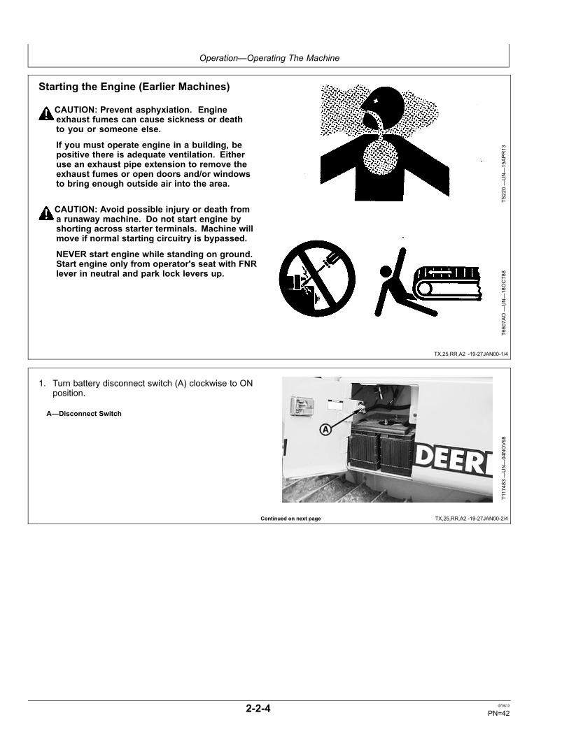
Starting the Engine (Earlier Machines)
CAUTION: Prevent asphyxiation. Engineexhaust fumes can cause sickness or deathto you or someone else.
If you must operate engine in a building, bepositive there is adequate ventilation. Eitheruse an exhaust pipe extension to remove theexhaust fumes or open doors and/or windowsto bring enough outside air into the area.
CAUTION: Avoid possible injury or death froma runaway machine. Do not start engine byshorting across starter terminals. Machine willmove if normal starting circuitry is bypassed.
NEVER start engine while standing on ground.Start engine only from operator's seat with FNRlever in neutral and park lock levers up.
TS220—UN—15APR13
T6607A
O—UN—18OCT88
1. Turn battery disconnect switch (A) clockwise to ONposition.
A—Disconnect Switch
T117483—UN—04NOV98
2-2-4 070813
PN=42

Operation—Operating The Machine
TX,25,RR,A2 -19-27JAN00-3/4
TX,25,RR,A2 -19-27JAN00-4/4
CAUTION: Use seat belt to avoid being injured orkilled in case of accident such as an overturn.
2. Sit in seat and fasten seat belt.
TS175—UN—23AUG88
NOTE: Controls and switches must be in the positionsdescribed, before starting engine.
3. FNR lever (C) to neutral position.
4. Park lock lever in up (locked) position (D).
IMPORTANT: To avoid engine damage, never startengine with engine speed control at high speed.
5. Engine speed control lever (A) to 1/3 speed.
6. Push horn switch (B) to sound horn.
IMPORTANT: Do not operate starter more than 20seconds at a time or starter may be damaged.If engine does not start, wait at least twominutes before trying again.
7. Turn key switch clockwise to turn engine until it starts.With engine running, adjust engine rpm to 1/2 speed.
A—Engine Speed ControlLever
B—Horn
C—FNR LeverD—Park Lock Lever
T118028—UN—12NOV98
T118007B
—UN—14JAN99
2-2-5 070813
PN=43

Operation—Operating The Machine
HG31779,00000BA -19-22JUL02-1/4
Continued on next page HG31779,00000BA -19-22JUL02-2/4
Starting the Engine (Later Machines)
CAUTION: Prevent asphyxiation. Engineexhaust fumes can cause sickness or deathto you or someone else.
If you must operate engine in a building, bepositive there is adequate ventilation. Eitheruse an exhaust pipe extension to remove theexhaust fumes or open doors and/or windowsto bring enough outside air into the area.
CAUTION: Avoid possible injury or death froma runaway machine. Do not start engine byshorting across starter terminals. Machine willmove if normal starting circuitry is bypassed.
NEVER start engine while standing on ground.Start engine only from operator's seat with FNRlever in N “Neutral” and park lock levers up.
TS220—UN—15APR13
T6607A
O—UN—18OCT88
1. Turn battery disconnect switch (A) clockwise to “On”position.
A—Disconnect Switch
T117483—UN—04NOV98
2-2-6 070813
PN=44

Operation—Operating The Machine
HG31779,00000BA -19-22JUL02-3/4
HG31779,00000BA -19-22JUL02-4/4
2. Sit in seat and fasten seat belt.
TS175—UN—23AUG88
NOTE: Controls and switches must be in the positionsdescribed, before starting engine.
3. Move FNR lever (C) to N.
4. Park lock lever in up (locked) position (D).
IMPORTANT: To avoid engine damage, never startengine with engine speed control at high speed.
5. Engine speed control lever (A) to 1/3 speed.
6. Push horn switch (B) to sound horn.
IMPORTANT: Do not operate starter more than 20seconds at a time or starter may be damaged. Ifengine does not start, wait at least two minutesbefore trying again. If engine does not start infour attempts, refer to Troubleshooting chapter.
7. Turn key switch clockwise to turn engine until it starts.With engine running, adjust engine rpm to 1/2 speed.See Engine Warm-Up in this section.
A—Engine Speed ControlLever
B—Horn
C—FNR LeverD—Park Lock Lever
T157847B
—UN—22JU
L02
T118007B
—UN—14JAN99
2-2-7 070813
PN=45

Operation—Operating The Machine
HG31779,00000BB -19-22JUL02-1/3
Continued on next page HG31779,00000BB -19-22JUL02-2/3
Starting Fluid (Cold Weather Start Aid)—IfEquippedA coolant heater without starting fluid is sufficient for coldstarting when temperature is down to —25°C (—13°F).The starting fluid option is required when ambienttemperature is below 0°C (32°F) and the machine is notequipped with a coolant heater.
Using Starting Fluid
CAUTION: Prevent possible injury from explodingcontainer. Starting fluid is highly flammable.Keep container away from heat, sparks, and openflame. Contents are pressurized. Do not punctureor incinerate container. Remove container frommachine if engine does not need starting fluid.
IMPORTANT: Prevent damage to engine. Use startingaid if necessary when temperatures are below0°C (32°F) and only when engine is COLD. Donot use ether aid and coolant heater together.
1. Turn key switch clockwise to “Start” position.
IMPORTANT: Excess starting fluid could damageengine; push starting aid button only whenengine is cold and cranking. Starting aidfluid is being injected into engine as longas you push and hold button.
2. After one or two revolutions of engine crankshaft, pushand hold starting aid button (A) for short intervals.Crank engine for 20 seconds maximum, then allow 2minutes between cranking periods.
A—Start Aid Button
TS281—UN—15APR13
T118117—UN—11DEC98
Earlier Machines
T157936B
—UN—22JU
L02
Later Machines
Replacing Start Aid Can
1. Turn container (B) counterclockwise to remove thestart aid can.
2. Remove safety cap and spray button from new can.
3. Turn can in start aid base (C) to install.
B—Container C—Base
T117489—UN—12NOV98
2-2-8 070813
PN=46

Operation—Operating The Machine
HG31779,00000BB -19-22JUL02-3/3
CED,OUO1032,1401 -19-24APR99-1/1
Operating Machine Without Start AidContainer Installed
If no starting fluid is needed, remove container and installdust cap (D).
D—Dust Cap
T8594A
F—UN—09NOV95
Using Coolant Heater—If Equipped
CAUTION: Prevent possible personal injury froman electrical shock. Use a heavy-duty, groundedcord to connect heater to electrical power.
Connect the coolant heater to 115-volt electrical power 10hours before you start the engine.
A coolant heater is recommended with the winch optionwhen ambient temperature is below —18°C (0°F).
A coolant heater without the ether aid is sufficient for coldstarting down to —25°C (—13°F).
2-2-9 070813
PN=47

Operation—Operating The Machine
Continued on next page CED,OUO1032,1406 -19-03SEP02-1/9
Operating Fuel-Fired Coolant Heater—IfEquipped
CAUTION: Prevent asphyxiation. Engineexhaust fumes can cause sickness or deathto you or someone else.
If you must operate engine in a building, bepositive there is adequate ventilation. Eitheruse an exhaust pipe extension to remove theexhaust fumes or open doors and/or windowsto bring enough outside air into the area.
CAUTION: Handle fuel carefully. Do not fill thefuel tank with heater turned on.
Do not operate heater in enclosed areas wherecombustible fumes may be present. Operateheater only in open areas to keep combustiblefumes away from machine.
Keep any flammable material a minimum distanceof 50 mm (2.0 in.) from exhaust tube.
The diesel fuel burning heater drawsfuel from machine fuel tank at a rate ofapproximately 0.1 gal/hr.
Ensure the fuel system is intact andthere are no leaks.
Use proper coolant. Failure to do so may causedamage of engine and/or personal injury.
IMPORTANT: The coolant heater requires that thecoolant in the system to be heated containthe proper mixture of water and coolant toprevent coolant from freezing or slushing. If thecoolant becomes slushy or frozen, the heaterscoolant pump cannot move the coolant causinga blockage of the circulating system.
Setting Time and Weekday:
T121396B
—UN—11MAY
99
A—TimeB—Program
C—Heating OnD—Backwards
E—ForwardsF—Display Window
1. Briefly press (A).
2. Time display 12:00 flashes.
3. Set the current time using (D) or (E).
4. When the time display stops flashing, the time hasbeen stored.
5. The weekday then begins to flash. Set the currentweekday using (D) or (E).
6. When the weekday display stops flashing, theweekday has been stored.
7. If the time is ON, the display continues to be displayed.If the time is OFF, the display disappears after 10seconds.
Adjusting Time and Weekday:
1. Press and hold down (A) until the time flashes.
2. Follow steps 3—7. If only the time is to be adjusted,the flashing weekday display can be skipped bypressing (A) twice.
2-2-10 070813
PN=48

Operation—Operating The Machine
CED,OUO1032,1406 -19-03SEP02-2/9
Continued on next page CED,OUO1032,1406 -19-03SEP02-3/9
3. When the weekday has been adjusted, pressing (A)causes the display to stop flashing and the weekdayto be stored.
Heating Without Programming (Time OFF)
T121396B
—UN—11MAY
99
1. Switch On Heating: Briefly press (C).
2. Display window (F) will display (H) and heating time(G). The default heating time is set to 120 minutes. Itcan be changed permanently or temporarily.
1. Temporarily Setting New Heating Time: Brieflypress (C).
2. To decrease heating time (one minute increments),press (D).
3. To increase heating time (120 minutes maximum),press (E).
1. Switch Off Heating: Briefly press (C).
2. The status display (H) disappears. Automatic after-runfor cool-down purposes will begin.
T121393—UN—11MAY
99
A—TimeB—ProgramC—Heating OnD—Backwards
E—ForwardsF—Display WindowG—Heating Time DisplayH—Heat Status Display
2-2-11 070813
PN=49
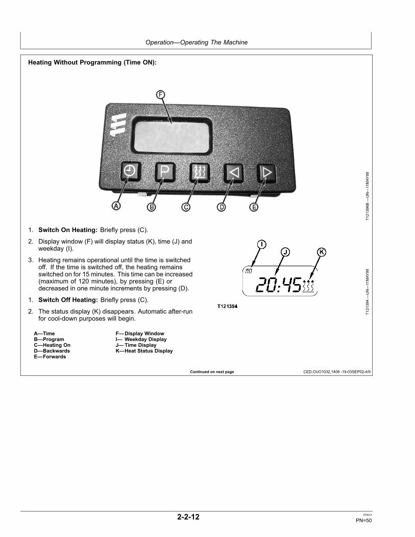
Operation—Operating The Machine
Continued on next page CED,OUO1032,1406 -19-03SEP02-4/9
Heating Without Programming (Time ON):
T121396B
—UN—11MAY
99
1. Switch On Heating: Briefly press (C).
2. Display window (F) will display status (K), time (J) andweekday (I).
3. Heating remains operational until the time is switchedoff. If the time is switched off, the heating remainsswitched on for 15 minutes. This time can be increased(maximum of 120 minutes), by pressing (E) ordecreased in one minute increments by pressing (D).
1. Switch Off Heating: Briefly press (C).
2. The status display (K) disappears. Automatic after-runfor cool-down purposes will begin.
A—TimeB—ProgramC—Heating OnD—BackwardsE—Forwards
F—Display WindowI— Weekday DisplayJ—Time DisplayK—Heat Status Display
T121394—UN—11MAY
99
2-2-12 070813
PN=50

Operation—Operating The Machine
Continued on next page CED,OUO1032,1406 -19-03SEP02-5/9
Programming Start of Heating
Selecting and Activating Memory: Three switch-ontimes within the following 24-hour period or one switch-on
time in seven days can be stored in memory. Only oneswitch-on time can be activated at a time.
T121396B
—UN—11MAY
99T121396B
—UN—11MAY
99
2-2-13 070813
PN=51

Operation—Operating The Machine
Continued on next page CED,OUO1032,1406 -19-03SEP02-6/9
T121395—UN—11MAY
99
1. To activate first memory: Press (B) once. Memorydisplay (L): 1 (default setting 12:00).
2. To activate second memory: Press (B) twice.Memory display (L): 2 (default setting 12:00).
3. To activate third memory: Press (B) once more.Memory display (L): 3 (default setting 12:00).
NOTE: Neutral status — no memory activated.
4. Press (B) repeatedly until the memory displaydisappears.
a. Program Switch On Heating Within 24 Hours:The correct program day is automatically displayed.No adjustment is necessary.
b. Set the program time:
1. Press (B) repeatedly until the desired memorydisplay (L) flashes 1, 2 or 3.
2. Briefly press and release (D) or (E). Theprogram time will flash.
3. Set the program time for heating using (D) or(E). Setting is only possible if the program timeis flashing.
4. To select another memory, press (B).
a. Program Switch On Heating After 24 Hours(Maximum Seven Days): Set the program time:
1. Press (B) repeatedly until the desired memorydisplay (L) flashes 1, 2 or 3.
2. Briefly press and release (D) or (E). Theprogram time will flash.
3. Set the program time for heating using (D) or(E). Setting is only possible if the program timeis flashing.
4. To select another memory, press (B).
T121395—UN—11MAY
99
A—TimeB—ProgramC—Heating OnD—Backwards
E—ForwardsF—Display WindowL—Memory Display
A—TimeB—ProgramC—Heating OnD—Backwards
E—ForwardsF—Display WindowL—Memory Display
b. Set the program day (the program day begins toflash approximately 5 seconds after the programtime has been set).
1. Set the program day for heating using (D) or (E).2. The program time and program day are stored
when the time display disappears or when thecurrent time appears. The memory display (L)indicates the activated memory. The flashingheating-on symbol (K) also indicates that amemory has been activated.
2-2-14 070813
PN=52

Operation—Operating The Machine
Continued on next page CED,OUO1032,1406 -19-03SEP02-7/9
Checking Activated Memory:
T121396B
—UN—11MAY
99
The program time of the displayed memory is displayed forapproximately five seconds. The display then disappearsor the current time is displayed (if the time is ON).
The program time display (J) and the program day (I) canthen be called up by pressing (B) once for five seconds.
Temperature Display
If an ambient temperature sensor is connected and thetime is activated, the temperature can be permanentlydisplayed by pressing (A) once. If the time is OFF, thetime temperature is displayed for 15 seconds by pressing(A) twice.
A—TimeB—ProgramC—Heating OnD—BackwardsE—Forwards
F—Display WindowI— Weekday DisplayJ—Time DisplayK—Heat Status Display
T121394—UN—11MAY
99
2-2-15 070813
PN=53

Operation—Operating The Machine
CED,OUO1032,1406 -19-03SEP02-8/9
CED,OUO1032,1406 -19-03SEP02-9/9
Service Codes
T121396B
—UN—11MAY
99
A—TimeB—Program
C—Heating OnD—Backwards
E—ForwardsF—Display Window
If a service code appears in display window (F): 1. Press (C) to turn heater off and on (twice maximum).
2. Check fuse (A).
3. Check exhaust tube (A) for blockage.4. See your authorized dealer.
A—Fuse
A—Exhaust Tube
T121419B
—UN—12MAY
99T121410B
—UN—11MAY
99
2-2-16 070813
PN=54

Operation—Operating The Machine
TX,25,BD2079 -19-14JAN08-1/1
02T,25,M24 -19-03AUG92-1/1
Using Booster Batteries—12 Volt System
T6508A
E1—UN—24OCT91
Single Battery Application
T6713A
I1—UN—24OCT91
Two Battery Application
A—Machine Battery(s) B—Booster Battery(s)
Before boost starting, machine must be properly shutdown and secured to prevent unexpected machinemovement when engine starts.
CAUTION: An explosive gas is produced whilebatteries are in use or being charged. Keep flamesor sparks away from the battery area. Make surethe batteries are charged in a well ventilated area.
Always remove grounded (—) battery clampfirst and replace it last.
IMPORTANT: The machine electrical system isa 12-volt negative (—) ground. Use only12-volt booster batteries.
1. Connect one end of the positive cable to the positiveterminal of the machine batteries and the other end tothe positive terminal of the booster batteries.
2. Connect one end of the negative cable to the negativeterminal of the booster batteries. Then connect otherend of the negative cable to the machine frame as faraway from the machine batteries as possible.
3. Start engine.
4. Immediately after starting engine, disconnect endof the negative cable from the machine frame anddisconnect the other end of the negative cable fromthe negative terminal of the booster batteries.
5. Disconnect positive cable from booster batteries andmachine batteries.
Engine Warm-Up1. After engine starts, run at 1/2 speed for 2 minutes. Do
not run at fast or slow idle.
2. Operate machine at less-than-normal loads andspeeds until engine is at normal operating temperature.
2-2-17 070813
PN=55

Operation—Operating The Machine
02T,25,J28 -19-15MAR93-1/1
TX,30,RR,A7 -19-07JAN00-1/1
Cold Weather Warm-UpNOTE: If hydraulic oil is cold, hydraulic functions
move slowly. Do not attempt machineoperations until hydraulic functions move atclose-to-normal cycle times.
In extremely cold conditions, an extended warming-upperiod will be necessary.
Avoid sudden operation of hydraulic functions until engineis thoroughly warmed up. Remove ice, snow, and mudfrom machine before operation.
1. Run engine at 1/2 speed for 5 minutes.
2. Cycle all hydraulic functions to distribute warmed oiluntil all functions operate freely.
Driving the Machine with Standard FNRLever (Earlier Machines)1. Start engine.
2. Move engine speed control lever (A) to desired enginerpm.
3. Move park lock lever (D) to down (unlocked) position.
NOTE: Transmission lever adjusts travel speed.
4. Move the transmission speed control lever (B) todesired setting. Number "3" is high transmissionspeed and number "1" is low transmission speed.
NOTE: Use decelerator pedal to adjust engine speed.
5. Depress decelerator pedal.
6. Move FNR lever (C) toward F to travel forward andtoward R to travel in reverse. Move FNR lever indesired turning direction to steer.
7. Slowly release decelerator to increase engine speedto the selected engine rpm.
A—Engine Speed ControlLever
B—Transmission SpeedControl Lever
C—FNR Control LeverD—Park Lock Lever
T117491—UN—12NOV98
T118007B
—UN—14JAN99
2-2-18 070813
PN=56
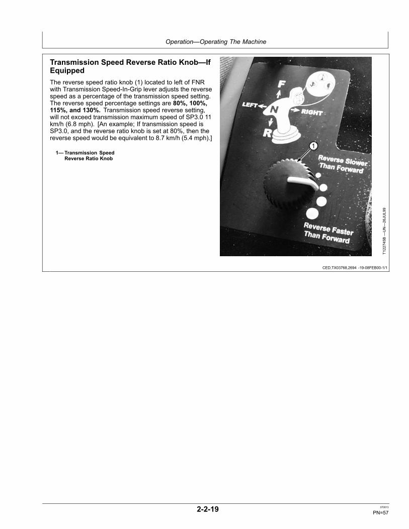
Operation—Operating The Machine
CED,TX03768,2694 -19-08FEB00-1/1
Transmission Speed Reverse Ratio Knob—IfEquippedThe reverse speed ratio knob (1) located to left of FNRwith Transmission Speed-In-Grip lever adjusts the reversespeed as a percentage of the transmission speed setting.The reverse speed percentage settings are 80%, 100%,115%, and 130%. Transmission speed reverse setting,will not exceed transmission maximum speed of SP3.0 11km/h (6.8 mph). [An example; If transmission speed isSP3.0, and the reverse ratio knob is set at 80%, then thereverse speed would be equivalent to 8.7 km/h (5.4 mph).]
1—Transmission SpeedReverse Ratio Knob
T122745B
—UN—26JU
L99
2-2-19 070813
PN=57

Operation—Operating The Machine
CED,TX03768,2680 -19-07DEC99-1/1
FNR with Transmission Speed In Grip—If Equipped
T122310B
—UN—16JU
L99
A—Transmission Speed In GripButton
B—Horn ButtonC—Transmission Reverse Ratio
Knob
Push the top of the FNR with transmission speed button(A) to increase transmission speed. Push the bottom ofthe switch to lower the machine transmission speed.
Push the horn button (B) to sound the machine horn whenneeded.
The transmission reverse ratio knob (C) allows theoperator to control the machine reverse speed different
from that of the machine forward speed. Turn the knobcounter-clockwise to decrease machine transmissionspeed.
The FNR with Transmission Speed-In-Grip lever controlsthe direction (forward and reverse), steering (left turn,right turn), pivot turn, and counter-rotation.
2-2-20 070813
PN=58

Operation—Operating The Machine
CED,TX03768,2704 -19-24FEB00-1/1
Driving the Machine using FNR withTransmission Speed In Grip—If Equipped(Earlier Machines)1. Fasten seat belt.
2. Park lock lever (5) must be in locked position (up).
3. Place FNR (2) with Transmission Speed-In-Grip to“Neutral” position.
4. Move engine speed control lever (4) to low idle position.
5. Start engine. Speed gauge (6) will display SP1.6.
6. Depress decelerator pedal.
7. Move park lock lever to down (unlocked) position.Speed gauge will display default transmission settingSP1.6.
NOTE: Transmission speed button and reversespeed ratio knob adjust travel speed and maybe adjusted at any time.
8. Place FNR with Transmission Speed-In-Grip lever indesired position.
9. Press transmission speed button (1) to desired setting(SP1.0—SP3.0) as seen in gauge. The transmissionspeed range is pre-set for a startup speed rangeof SP1.6. The transmission speed range can varydepending on operator's preference from SP1 to SP3(machine speed can vary from 0 to 5 mph).
10. Adjust the reverse transmission speed ratio knob (3).(Reverse speed ratio of 80%, 100%, 115%, or 130%of transmission speed.)
11. Slowly release decelerator pedal to move machine.
12. Move engine speed lever to a desired rpm setting.
13. Move FNR with Transmission Speed-In-Grip lever indesired turning direction to steer.
1—Transmission Speed Button2—FNR with Transmission
Speed-In-Grip Lever3—Reverse Speed Ratio Knob
4—Engine Speed Control5—Park Lock Lever6—Transmission Speed
Setting Gauge
T157847C
—UN—22JU
L02
T127190B
—UN—07JAN00
T127196B
—UN—07JAN00
2-2-21 070813
PN=59

Operation—Operating The Machine
TE14778,000000D -19-27AUG03-1/1
Driving the Machine using FNR withTransmission Speed In Grip—If Equipped(Later Machines)1. Fasten seat belt.
2. Park lock lever (5) must be in locked position (up).
3. Place FNR (2) with Transmission Speed-In-Grip to“Neutral” position.
4. Move engine speed control lever (4) to low idle position.
5. Start engine.
6. Depress decelerator pedal.
7. Move park lock lever to down (unlocked) position.Speed gauge will display default transmission settingSP1.6.
NOTE: Transmission speed button and reversespeed ratio knob adjust travel speed and maybe adjusted at any time.
8. Place FNR with Transmission Speed-In-Grip lever indesired position.
9. Press transmission speed button (1) to desired setting(SP1.0—SP3.0) as seen in display window. Thetransmission speed range is pre-set for a startupspeed range of SP1.6. The transmission speed rangecan vary depending on operator's preference from SP1to SP3 (machine speed can vary from 0 to 5 mph).
10. Adjust the reverse transmission speed ratio knob (3).(Reverse speed ratio of 80%, 100%, 115%, or 130%of transmission speed.)
11. Slowly release decelerator pedal to move machine.
12. Move engine speed lever to a desired rpm setting.
13. Move FNR with Transmission Speed-In-Grip lever indesired turning direction to steer.
1—Transmission Speed Button2—FNR with Transmission
Speed-In-Grip Lever3—Reverse Speed Ratio Knob
4—Engine Speed Control5—Park Lock Lever6—Display Window
T157847C
—UN—22JU
L02
T127190B
—UN—07JAN00
T157934B
—UN—22JU
L02
2-2-22 070813
PN=60

Operation—Operating The Machine
CED,OUO1032,1073 -19-03SEP02-1/1
Steering the Machine
CAUTION: If the machine does not steerproperly, do not operate. See your authorizeddealer for service.
Move lever forward to move machine forward.
Move lever rearward to move machine in reverse.
Movement of lever in range (A) (spring force) will slow onetrack to turn machine in desired direction.
Further movement to range (B) (no spring force) will stopone track to make a pivot turn in desired direction.
Continued movement in range (C) (increased spring force)will move one track forward and one track in reverse tocounter-rotate machine in desired direction.
A—Range (Spring Force)B—Range (No Spring Force)
C—Range (Increased SpringForce)
T118031—19—16DEC98
T118740—19—15DEC98
2-2-23 070813
PN=61

Operation—Operating The Machine
CED,TX03768,2695 -19-08FEB00-1/1
Steering using FNR with Transmission SpeedIn Grip Lever—If EquippedThe FNR (2) with Transmission Speed-In-Grip controls thedirection (forward and reverse), the steering (left turn, rightturn), pivot turn, and counter-rotation. Moving the FNRfully right or left will cause the machine to counter-rotate.
1—Transmission SpeedControl Button
2—FNR with TransmissionSpeed-In-Grip Control
3—Transmission SpeedReverse Ratio Knob
4—Engine Speed Control
T157847C
—UN—22JU
L02
T122746B
—UN—29JU
L99
2-2-24 070813
PN=62

Operation—Operating The Machine
CED,OUO1032,1072 -19-28OCT98-1/1
CED,TX03768,2703 -19-18FEB00-1/1
Using Engine Speed Control LeverTo increase engine speed, move engine speed controllever (A) rearward to position (B) (rabbit). To decreaseengine speed, move lever forward to position (C) (turtle).
A—Engine Speed ControlLever
B—Fast Idle Position
C—Slow Idle Position
T118029—UN—12NOV98
Travel Speed Using FNR Transmission SpeedIn the Grip—If EquippedHydrostatic dual path transmission provides variable travelspeed (SP1.0—SP3.0) ranging from 0—11 km/h (0—6.8mph) in forward or reverse. Reverse speed ratios of 80%,100%, 115%, and 130% until maximum mph is reached,from 0—11 km/h (0—5 mph) in reverse. Transmissionspeed default speed of SP1.6 will be displayed by movingpark lock lever or pushing FNR Speed in the grip button(1 and 3).
1—Transmission Speed Button(increase)
2—Horn Button
3—Transmission Speed Button(decrease)
T128172B
—UN—08FE
B00
2-2-25 070813
PN=63

Operation—Operating The Machine
CED,TX03768,2696 -19-18FEB00-1/1
CED,OUO1032,1070 -19-28OCT98-1/1
CED,TX03768,2699 -19-09FEB00-1/1
Foot Pedals
CAUTION: Prevent possible injury fromunexpected machine movement. Pushing onbrake pedal will stop machine abruptly.
NOTE: Release of brake pedal will allow machine to move.
Brake pedal (B) should not be used to stop machineduring normal operating conditions. Pushing on brakepedal will stop machine abruptly. Travel will resume aspedal is released.
Pushing on decelerator pedal (A) will slow engine rpmand reduce machine ground speed.
T118042C
—UN—02DEC98
A—Decelerator Pedal B—Brake Pedal
Using Park Lock Lever
CAUTION: Prevent possible injury fromunexpected machine movement. Alwaysmove park lock lever to up (locked) positionbefore starting or dismounting.
When park lock lever is in up (locked) position (B), FNRlever can move but will not operate the machine.
When park lock lever is in down (unlocked) position (A),FNR lever can move machine.
If park lock lever is pulled down while the FNR lever isin forward or reverse, the machine will not move. PutFNR lever in neutral, then raise and lower the park lever.Machine is now operable.
A—Park Lock Lever Unlocked B—Park Lock Lever Locked
T118001B
—UN—11NOV98
T118007C
—UN—14JAN99
Stopping the MachineNOTE: Park brake automatically engages when
engine is not running.
Stop machine by doing one of the following:
• Push decelerator pedal.• Push brake pedal.
• Move FNR lever to N.• Push park lock lever to up (locked) position.
CAUTION: Machine may overturn if blade isdropped when moving rapidly down a steep hill.
• As a last resort, drop blade to stop machine.
2-2-26 070813
PN=64

Operation—Operating The Machine
HG31779,00000BC -19-22JUL02-1/1
Parking the Machine1. Park machine on a level surface.
2. Lower equipment to the ground.
3. Move FNR control lever (1) to N.
NOTE: Park brake automatically engages whenengine is not running or park lock lever isin up (locked) position.
4. Move park lock lever (3) to up (locked) position.
IMPORTANT: To avoid damage to turbocharger(if equipped), run engine at 1/2 speed noload for two minutes.
5. Run engine at 1/2 speed no load for 2 minutes.
6. Move engine speed control lever (2) to slow idleposition.
7. Turn key switch to “Off” to stop engine.
8. Remove key from switch.
9. Release hydraulic pressure by moving control leveruntil equipment does not move.
10. Turn battery disconnect switch off.
1—FNR with TransmissionSpeed-In Grip Lever
2—Engine Speed ControlLever
3—Park Lock Lever
T157847F
—UN—29AUG02
T118007D
—UN—28AUG02
2-2-27 070813
PN=65

Operation—Operating The Machine
CED,OUO1032,1118 -19-24APR99-1/2
CED,OUO1032,1118 -19-24APR99-2/2
Blade Pitch OperationYou may want to change the pitch of the blade dependingon the type of work you are doing and the soil conditionsyou are dozing, or to change the feel of the dozer tooperator's preference.
Pitching the Blade Forward Advantages:
With the top of blade pitched forward (A), the blade willnot carry as much soil. The weight of the soil carried bythe blade adds to the weight of the dozer and moves thebalance of weight on the tracks forward. This can causethe front idlers of the crawler to sink in loose or soft soils.When the idlers sink, the blade cuts unevenly into thesoil. With the blade forward, the dozer balance does notchange as much with a full blade; therefore, the tendencyfor idlers to sink is reduced.
With the blade forward, there is less of a tendency for dirtto come over the back of the blade when dozing uphill. Itis also easier to drop dirt at the end of a push when dozinguphill or when dozing very sticky materials.
Pitching the Blade Back Advantages:
With the blade pitched back (B), the cutting edge liesmore horizontally resulting in a heavier cut into soils.Having the cutting edge more horizontal also provides asmoother cut in heavy soils. More soil is carried by the
T118184B
—UN—25NOV98
450H Shown
A—Forward Pitch B—Back Pitch
blade when it is pitched back. Carrying more soil on theblade adds to the weight of the dozer. This added weightcan increase push force in heavy soils. The soil carriedby the blade also moves the balance of weight forward onthe machine. In heavy soils, this can be an advantagebecause the increased weight can help keep the front ofthe machine down and keep the cutting edge penetratingduring heavy cutting.
Changing the Pitch:
To determine which link is assembled to the blade, look atthe right side of the pitch link (A). Cast into the link will beone of the following: FORWARD, MID or BACK.
The standard pitch link is a universal (MID) position link.
There are two optional pitch links available. TheFORWARD link performs better in sand, stone gradingand has best visibility to cutting edge. The BACK linkperforms better in cutting, backfilling, and moving largequantities of material.
See your authorized dealer to obtain either of the optionallinks.
T118191C
—UN—02DEC98
A—Pitch Link
2-2-28 070813
PN=66

Operation—Operating The Machine
CED,OUO1032,1119 -19-14JAN08-1/1
CED,OUO1032,1120 -19-14JAN08-1/1
Operating BladeIMPORTANT: To avoid overheating of hydraulic oil,
allow control lever to return to neutral whencylinders reach the end of their travel.
Move control lever rearward to raise blade. Move controllever forward to lower blade.
Move lever to full forward detent for float position. Thisposition allows the blade to follow the contour of theground. Manually release lever from this position.
T121338C
—UN—11MAY
99
Tilting BladeMove the blade control lever left to tilt the blade left.
Move the blade control lever right to tilt the blade right.
A—Tilt Blade Left B—Tilt Blade Right
T121338D
—UN—11MAY
99T6508A
W—UN—19MAY
89
2-2-29 070813
PN=67

Operation—Operating The Machine
CED,OUO1032,1121 -19-14JAN08-1/1
Angling BladeTwist lever to right to angle blade to right.
Twist lever to left to angle blade to left.
T121338E
—UN—11MAY
99T118641—UN—01DEC98
2-2-30 070813
PN=68

Operation—Operating The Machine
TX,36,FF2210 -19-03SEP02-1/1
Operating Winch—If Equipped
CAUTION: Always be sure rear screen betweenwinch and operating compartment is in placebefore operating winch.
Operate the winch only from operator's station.
A coolant heater is recommended with winch option ifambient temperature is below —18°C (0°F).
Before operating winch, place winch control in free spoolto circulate oil through winch until transmission oil reachesoperating temperature.
• Move lever to FREE SPOOL (A) position so cable canbe pulled out freely.• Move lever to the BRAKE OFF (B) position so cablecan be pulled out with tension.• Move lever to the BRAKE ON (C) position to hold cable.• Move lever to POWER IN (D) position to wind cableon drum• Move lever to POWER OUT (E) position (if equipped) tounwind cable from drum.
A—Free SpoolB—Brake OffC—Brake On
D—Power InE—Power Out
T7440B
G—UN—20DEC90
Standard Control Pattern
T7440B
H—UN—20DEC90
Power In, Power Out Control Pattern
2-2-31 070813
PN=69
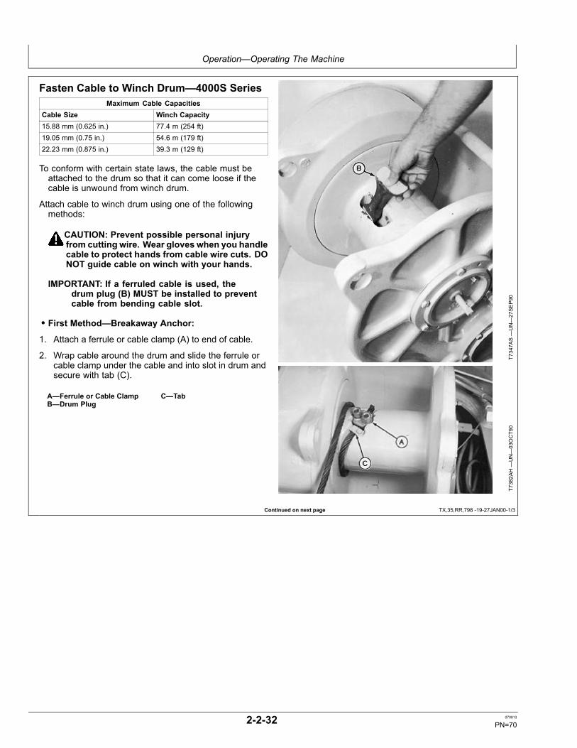
Operation—Operating The Machine
Continued on next page TX,35,RR,798 -19-27JAN00-1/3
Fasten Cable to Winch Drum—4000S SeriesMaximum Cable Capacities
Cable Size Winch Capacity15.88 mm (0.625 in.) 77.4 m (254 ft)19.05 mm (0.75 in.) 54.6 m (179 ft)22.23 mm (0.875 in.) 39.3 m (129 ft)
To conform with certain state laws, the cable must beattached to the drum so that it can come loose if thecable is unwound from winch drum.
Attach cable to winch drum using one of the followingmethods:
CAUTION: Prevent possible personal injuryfrom cutting wire. Wear gloves when you handlecable to protect hands from cable wire cuts. DONOT guide cable on winch with your hands.
IMPORTANT: If a ferruled cable is used, thedrum plug (B) MUST be installed to preventcable from bending cable slot.
• First Method—Breakaway Anchor:
1. Attach a ferrule or cable clamp (A) to end of cable.
2. Wrap cable around the drum and slide the ferrule orcable clamp under the cable and into slot in drum andsecure with tab (C).
A—Ferrule or Cable ClampB—Drum Plug
C—Tab
T7347A
S—UN—27SEP90
T7382A
H—UN—03OCT90
2-2-32 070813
PN=70
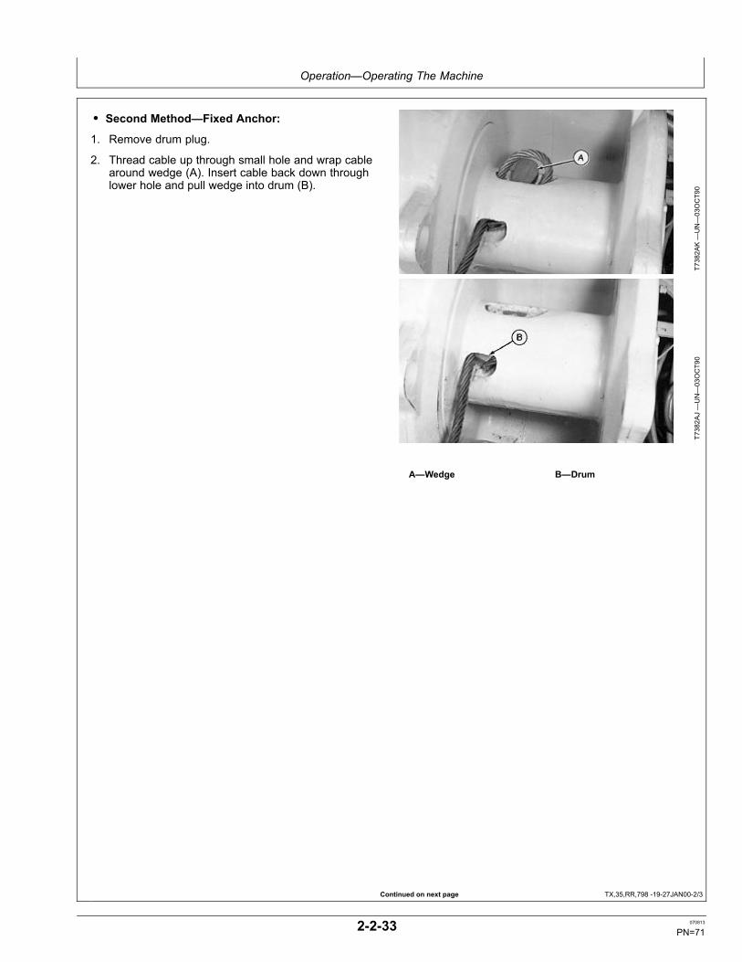
Operation—Operating The Machine
Continued on next page TX,35,RR,798 -19-27JAN00-2/3
• Second Method—Fixed Anchor:
1. Remove drum plug.
2. Thread cable up through small hole and wrap cablearound wedge (A). Insert cable back down throughlower hole and pull wedge into drum (B).
T7382A
K—UN—03OCT90
T7382A
J—UN—03OCT90
A—Wedge B—Drum
2-2-33 070813
PN=71

Operation—Operating The Machine
TX,35,RR,798 -19-27JAN00-3/3
• Third Method:
IMPORTANT: If you unwind cable below one turnon drum, cable will come off drum.
1. Remove drum plug (B).
CAUTION: Prevent possible injury from cablewire. Wear gloves when handling cable toprotect hands from cable wire cuts. DO NOTguide cable on winch with your hands.
2. Thread cable up through small hole and insert cableback down through lower hole. Pull loop into drum.
3. Adjust free spool drag to operator's preference. SeeWinch Free Spool Drag Adjustment in this section.
NOTE: Factory free spool drag setting was donewithout cable; adjust free spool drag to operator'spreference when cable is added.
B—Drum Plug
T7347A
S—UN—27SEP90
T7382A
I—UN—03OCT90
2-2-34 070813
PN=72

Operation—Operating The Machine
TX,35,RR4679 -19-10JAN12-1/1
JH91824,00002EA -19-22JUL10-1/1
Winch Free Spool Drag AdjustmentThe winch drum drag can be adjusted to operator'spreference.
1. Start engine.
2. Lower equipment to ground.
3. Engage park brake.
4. Place winch control handle in FREE SPOOL position.
5. Loosen nut (A).
6. Adjust slotted shaft to desired winch drum drag.
7. Tighten nut.
A—Nut
T118240B
—UN—12NOV98
Winch (right side)
Avoid Track DamageIMPORTANT: Avoid machine damage. If machine
is equipped with a sealed and lubricated
track, avoid water being forced between theplastic pins and rubber plugs while washingmachine with pressure washer.
2-2-35 070813
PN=73

Operation—Operating The Machine
02T,40,K36 -19-07JAN00-1/1
Loading Machine on a Trailer
1. Keep the trailer bed clean.
2. Put chock blocks (A) against truck wheels.
3. Use a ramp or loading dock. Ramps must be strongenough, have a low angle, and be of correct height.
4. Fasten seat belt before starting engine.
5. Load and unload the machine on a level surface.
CAUTION: Prevent possible injury fromunexpected machine movement. Wheneverpossible, back the machine onto the trailerto prevent possible tipping.
6. Drive the machine onto the ramps squarely.
7. The centerline of the machine should be over thecenterline of the trailer.
8. Lower all equipment onto blocks.
9. Move FNR lever to N.
10. Move park lock lever to lock position.
IMPORTANT: To avoid damage to turbocharger(if equipped), run engine at 1/2 speed noload for two minutes.
11. Run engine at 1/2 speed no load for 2 minutes.
12. Move engine speed control lever to slow idle position.
13. Turn key switch to “Off”. Stop engine.
14. Remove key from switch.
15. Release hydraulic pressure by moving control leveruntil equipment does not move.
T87155
—UN—09NOV88
A—Chock Blocks
16. Turn battery disconnect switch off.
17. Cover exhaust opening to prevent entry of wind andwater.
IMPORTANT: Fasten chains or cables to machineframe or track chain links. Do not place chains orcables over or against hydraulic lines or hoses.
18. Fasten each corner of the machine to the trailer with achain or cable.
• Front: Use towhook eye on bottom of the machineframe front end.• Side: Use inside edge of track shoe.• Rear: Use outer edge of track shoe or drawbar (ifequipped).
2-2-36 070813
PN=74

Operation—Operating The Machine
CED,OUTX466,1206 -19-24APR99-1/3
Continued on next page CED,OUTX466,1206 -19-24APR99-2/3
Releasing the Park Brake to Tow the MachineOrder CO2 Inflation Kit and attaching hardware throughyour authorized dealer.
CAUTION: Prevent possible injury fromunexpected machine movement. Do not try tostart engine when towing. Extensive machinedamage and/or personal injury may result.
IMPORTANT: DO NOT tow machine faster than2.4 km/h (1.5 mph) or extensive machinedamage may result.
1. Stop engine.
2. Move park lock lever down to unlocked position.
3. Remove rubber mat and floor plate from operator'sstation.
NOTE: Multi-function valves can be turned out using a1 1/4 in. socket and a flexible head ratchet.
4. TO TOW MACHINE FORWARD: Both front and rearpump top multi-function relief valves (1) MUST beturned out (counterclockwise) 1/2 to 1 turn and blademust be raised off the ground. (If engine will crank butwill not start, blade can be raised by cranking enginewhile holding blade raise function on control valve.)
TO TOW MACHINE IN REVERSE: Both front andrear pump bottom multi-function valves (2) MUST beturned out (counterclockwise) 1/2 to 1 turn.
5. Disconnect quick coupler (3).
1—Forward Multi-FunctionValve (top)
2—Reverse Multi-FunctionValve (bottom)
3—Quick Coupler
T118899B
—UN—16DEC98
T119030B
—UN—16DEC98
6. Assemble the CO2 Inflation Kit and attachinghardware.
7. Install CO2 assembly to hose coupler end.
1—AM102420 Male QuickCoupler
2—Parker Adapter 0502-6-4 (9/16 in. to 1/4 in. pipe)
3—R27908 Adapter (1/4 in. to1/8 in. pipe)
4—AT119575 Adapter5—AT221000 CO2 Inflation Kit
(Includes inflation canisterand cartridge)
T119431B
—UN—07JAN99
CO2 Inflation Kit and Attaching Hardware
2-2-37 070813
PN=75

Operation—Operating The Machine
CED,OUTX466,1206 -19-24APR99-3/3
IMPORTANT: Release brakes using CO2 with aMINIMUM pressure of 200 psi and a MAXIMUMpressure of 400 psi. DO NOT exceed the limitsof the charge pressure gauge on dash.
NOTE: The brakes initially start to release atapproximately 150 psi and are fully released atapproximately 190 psi. With the park lock leverdown, monitor the pressure on the transmissionoil pressure gauge on the instrument panel.
8. While sitting in the operator's seat, watch chargepressure gauge on dash when releasing brakesusing CO2 assembly. Pressurize brake circuit toapproximately 200 psi.
IMPORTANT: DO NOT tow machine faster than2.4 km/h (1.5 mph) or extensive machinedamage may result.
NOTE: Engine does not have to be running to towmachine.
9. Tow the machine.
10. After the machine is towed, step on the brakesto release pressure. Remove CO2 assembly andreconnect coupler. Tighten multi-function valve locknut to 79 N·m (58 lb-ft). See your authorized dealerfor repair.
SpecificationMulti-Function Valve LockNut—Torque................................................................... 79 N·m (58 lb-ft)
T119432B
—UN—07JAN99
T121134—UN—20APR99
2-2-38 070813
PN=76
Maintenance—Machine
DX,FUEL1 -19-11APR11-1/1
TX,45,JC2126 -19-15AUG97-1/1
DX,FUEL6 -19-14APR11-1/1
Diesel Fuel
Consult your local fuel distributor for properties of thediesel fuel available in your area.
In general, diesel fuels are blended to satisfy the lowtemperature requirements of the geographical area inwhich they are marketed.
Diesel fuels specified to EN 590 or ASTM D975 arerecommended. Renewable diesel fuel produced byhydrotreating animal fats and vegetable oils is basicallyidentical to petroleum diesel fuel. Renewable diesel thatmeets EN 590 or ASTM D975 is acceptable for use at allpercentage mixture levels.
Required Fuel Properties
In all cases, the fuel shall meet the following properties:
Cetane number of 43 minimum. Cetane number greaterthan 47 is preferred, especially for temperatures below–20°C (–4°F) or elevations above 1500 m (5000 ft.).
Cold Filter Plugging Point (CFPP) should be at least 5°C(9°F) below the expected lowest temperature or CloudPoint below the expected lowest ambient temperature.
Fuel lubricity should pass a maximum scar diameter of0.45 mm as measured by ASTM D6079 or ISO 12156-1.
Diesel fuel quality and sulfur content must comply withall existing emissions regulations for the area in whichthe engine operates. DO NOT use diesel fuel with sulfurcontent greater than 10 000 mg/kg (10 000 ppm).
Sulfur content for Interim Tier 4 and Stage III B engines
• Use ONLY ultra low sulfur diesel (ULSD) fuel with amaximum of 15 mg/kg (15 ppm) sulfur content.
Sulfur Content for Tier 3 and Stage III A Engines
• Use of diesel fuel with sulfur content less than 1000mg/kg (1000 ppm) is RECOMMENDED• Use of diesel fuel with sulfur content 1000–5000 mg/kg(1000–5000 ppm) REDUCES oil and filter changeintervals.
• BEFORE using diesel fuel with sulfur content greaterthan 5000 mg/kg (5000 ppm), contact your John Deeredealer
Sulfur Content for Tier 2 and Stage II Engines
• Use of diesel fuel with sulfur content less than 500mg/kg (500 ppm) is RECOMMENDED.• Use of diesel fuel with sulfur content 500–5000 mg/kg(500–5000 ppm) REDUCES the oil and filter changeinterval• BEFORE using diesel fuel with sulfur content greaterthan 5000 mg/kg (5000 ppm), contact your John Deeredealer
Sulfur Content for Other Engines
• Use of diesel fuel with sulfur content less than 5000mg/kg (5000 ppm) is recommended.• Use of diesel fuel with sulfur content greater than 5000mg/kg (5000 ppm) REDUCES the oil and filter changeintervals.
IMPORTANT: Do not mix used diesel engine oil or anyother type of lubricating oil with diesel fuel.
IMPORTANT: Improper fuel additive usage maycause damage on fuel injection equipmentof diesel engines.
Low Sulfur Diesel Fuel ConditionerWhen possible, use existing fuel formulations for enginesused off-highway. This fuel will not require any additivesto provide good performance and engine reliability.However, many local fuel distributors will not carry bothlow and regular sulfur diesel fuels.
If the local fuel distributor will supply only low sulfur fuel,order and use John Deere PREMIUM DIESEL FUEL
CONDITIONER. It provides lubricating properties alongwith other useful benefits, such as cetane improver,anti-oxidant, fuel stabilizer, corrosion inhibitor and others.John Deere PREMIUM DIESEL FUEL CONDITIONER isspecifically for use with low sulfur fuels. Nearly all otherdiesel fuel conditioners only improve cold weather flow andstabilize long-term fuel storage. They do not contain thelubrication additives needed by rotary fuel injection pumps.
Testing Diesel FuelA fuel analysis program can help to monitor the qualityof diesel fuel. The fuel analysis can provide criticaldata such as cetane number, fuel type, sulfur content,water content, appearance, suitability for cold weather
operations, bacteria, cloud point, acid number, particulatecontamination, and whether the fuel meets specification.
Contact your John Deere dealer for more information ondiesel fuel analysis.
3-1-1 070813
PN=77

Maintenance—Machine
DX,FUEL4 -19-14APR11-1/1
AM40430,00000AA -19-03NOV08-1/1
Handling and Storing Diesel Fuel
CAUTION: Reduce the risk of fire. Handle fuelcarefully. DO NOT fill the fuel tank when engineis running. DO NOT smoke while you fill thefuel tank or service the fuel system.
Fill the fuel tank at the end of each day's operation toprevent water condensation and freezing during coldweather.
Keep all storage tanks as full as practicable to minimizecondensation.
Ensure that all fuel tank caps and covers are installedproperly to prevent moisture from entering. Monitor watercontent of the fuel regularly.
When using biodiesel fuel, the fuel filter may require morefrequent replacement due to premature plugging.
Check engine oil level daily prior to starting engine. Arising oil level may indicate fuel dilution of the engine oil.
IMPORTANT: The fuel tank is vented through thefiller cap. If a new filler cap is required, alwaysreplace it with an original vented cap.
When fuel is stored for an extended period or if there is aslow turnover of fuel, add a fuel conditioner to stabilize thefuel and prevent water condensation. Contact your fuelsupplier for recommendations.
Alternative and Synthetic Lubricants
Conditions in certain geographical areas may requirelubricant recommendations different from those printedin this manual. Some John Deere brand coolants andlubricants may not be available in your location.
Synthetic lubricants may be used if they meet theperformance requirements as shown in this manual.
The temperature limits and service intervals shown in thismanual apply to both conventional and synthetic oils.
Re-refined base stock products may be used if thefinished lubricant meets the performance requirements.
Avoid mixing different brands or types of oils. Oilmanufacturers blend base stock and additives tocreate their oils and to meet certain specifications andperformance requirements. Mixing different oils caninterfere with proper functioning of these formulations anddegrade lubricant performance.
Consult your authorized John Deere dealer to obtainspecific information and recommendations.
3-1-2 070813
PN=78

Maintenance—Machine
DX,ENOIL4 -19-20APR11-1/1
Diesel Engine Break-In Oil
New engines are filled at the factory with either JohnDeere Break-In™ or John Deere Break-In Plus™Engine Oil. During the break-in period, add John DeereBreak-In™ or Break-In Plus ™ Engine Oil, respectively,as needed to maintain the specified oil level.
Operate the engine under various conditions, particularlyheavy loads with minimal idling, to help seat enginecomponents properly.
If John Deere Break-In Engine Oil is used during the initialoperation of a new or rebuilt engine, change the oil andfilter at a maximum of 250 hours.
If John Deere Break-In Plus Engine Oil is used, changethe oil and filter at a minimum of 100 hours and amaximum equal to the interval specified for John DeerePlus-50™ II or Plus-50 oil.
After engine overhaul, fill the engine with either JohnDeere Break-In™ or Break-In Plus™ Engine Oil.
If John Deere Break-In or Break-In Plus Engine Oil isnot available, use an SAE 10W-30 viscosity grade dieselengine oil meeting one of the following and change the oiland filter at a maximum of 100 hours of operation:
• API Service Classification CE• API Service Classification CD
• API Service Classification CC• ACEA Oil Sequence E2• ACEA Oil Sequence E1
IMPORTANT: Do not use Plus-50™ II, Plus-50 orengine oils meeting any of the following for theinitial break-in of a new or rebuilt engine:
API CJ-4 ACEA E9API CI-4 PLUS ACEA E7API CI-4 ACEA E6API CH-4 ACEA E5API CG-4 ACEA E4API CF-4 ACEA E3API CF-2API CF
These oils will not allow the engine tobreak in properly.
John Deere Break-In Plus™ Engine Oil can be used forall John Deere diesel engines at all emission certificationlevels.
After the break-in period, use John Deere Plus-50™II, John Deere Plus-50, or other diesel engine oil asrecommended in this manual.
Break-In is a trademark of Deere & Company.Break-In Plus is a trademark of Deere & CompanyPlus-50 is a trademark of Deere & Company.
3-1-3 070813
PN=79

Maintenance—Machine
DX,ENOIL -19-14APR11-1/1
TX,45,RR5122 -19-14JAN08-1/1
Diesel Engine Oil
Use oil viscosity based on the expected air temperaturerange during the period between oil changes.
John DeerePlus-50™ II oil is preferred.
John Deere Plus-50™ is also recommended.
Other oils may be used if they meet one or more of thefollowing:
• John Deere Torq-Gard™• API Service Category CJ-4• API Service Category CI-4 PLUS• API Service Category CI-4• API Service Category CH-4• API Service Category CG-4• API Service Category CF-4• ACEA Oil Sequence E9• ACEA Oil Sequence E7• ACEA Oil Sequence E6• ACEA Oil Sequence E5• ACEA Oil Sequence E4• ACEA Oil Sequence E3• ACEA Oil Sequence E2
If oils meeting API CG-4, API CF-4, or ACEA E2 are used,reduce the service interval by 50%.
Multi-viscosity diesel engine oils are preferred.
Diesel fuel quality and fuel sulfur content must complywith all existing emissions regulations for the area inwhich the engine operates.
SA
E 3
0 SA
E 4
0
SA
E 0
W-4
0
50 Co
40 Co
30 Co
20 Co
10 Co
0 C o
-10 Co
-20 Co
-30 Co
-40 Co
122 Fo
50 Fo
32 Fo
14 Fo
-4 Fo
-22 Fo
-40 Fo
104 Fo
68 Fo
86 Fo
SA
E 5
W-3
0
SA
E 1
0W-3
0
SA
E 1
0W-4
0
SA
E-1
5W-4
0
TS1687
—UN—18JU
L07
Oil Viscosities for Air Temperature Ranges
If diesel fuel with sulfur content greater than 5000 mg/kg(5000 ppm) is used, reduce the service interval by 50%.
DO NOT use diesel fuel with sulfur content greater than10 000 mg/kg (10 000 ppm).
Plus-50 is a trademark of Deere & CompanyTorq-Gard is a trademark of Deere & Company
Track Rollers, Front Idler and Carrier RollerOilUse oil viscosity based on the expected air temperaturerange during the period between oil changes.
The following oils are preferred:
• John Deere GEAR LUBRICANT (SAE 80W90)
• John Deere EXTREME-GARDThe following oils are recommended:
• API Service Classification GL-5 gear oil (SAE 80W90)• Arctic oils such as (MIL-L-10324A) may be used attemperatures below –30°C (–11°F).
3-1-4 070813
PN=80
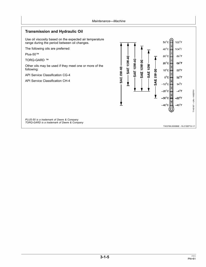
Maintenance—Machine
TX03768,0000B8E -19-21SEP10-1/1
Transmission and Hydraulic Oil
Use oil viscosity based on the expected air temperaturerange during the period between oil changes.
The following oils are preferred:
Plus-50™
TORQ-GARD ™
Other oils may be used if they meet one or more of thefollowing:
API Service Classification CG-4
API Service Classification CH-4
T145167—UN—14SEP01
PLUS-50 is a trademark of Deere & CompanyTORQ-GARD is a trademark of Deere & Company
3-1-5 070813
PN=81

Maintenance—Machine
BT40170,0000002 -19-13JAN04-1/1
Final Drive Oil
T8448AT—19—26JU
N95
Depending on the expected air temperature rangebetween oil changes, use oil viscosity shown on the chartabove.
John Deere HY-GARD ® is preferred.
Other oils may be used if they meet the following:
• John Deere API GL-5 Gear Oil (SAE 80W90)
Arctic oils (such as Military Specifications MIL-L-46167B)may be used at temperatures below — 30°C (—22°F).
HY-GARD is a registered trademark of Deere & Company.
3-1-6 070813
PN=82

Maintenance—Machine
BT40170,0000001 -19-13JAN04-1/1
DX,GREA1 -19-14APR11-1/1
Winch OilUse oil viscosity based on expected air temperature rangeduring period between oil changes.
The following oils are preferred:
• John Deere HY-GARD®• John Deere Low Viscosity HY-GARD®
Other oils may be used if they meet one of the following:
• John Deere Standard JDM J20C• John Deere Standard JDM J20D
Use the following oil when a biodegradable fluid isrequired:
• John Deere BIO-HY-GARD™Engine oils may be used if they meet both CaterpillarTO-2 test AND one or more of API ServiceClassifications CE, CD or CC.Other oils may be used if they meet John DeereStandard JDM J20C or J20D.Oils meeting Military Specification MIL-L-46167A maybe used as arctic oils.
TS1660
—UN—10OCT97
HY-GARD is a trademark of Deere & CompanyBIO-HY-GARD is a trademark of Deere & Company
GreaseUse grease based on NLGI consistency numbers and theexpected air temperature range during the service interval.
John Deere SD Polyurea Grease is preferred.
The following greases are also recommended:
• John Deere HD Lithium Complex Grease• John Deere HD Water Resistant Grease• John DeereGREASE-GARD™Other greases may be used if they meet the following:
• NLGI Performance Classification GC-LBIMPORTANT: Some types of grease thickeners are not
compatible with others. Consult your greasesupplier before mixing different types of grease.
TS1673
—UN—31OCT03
Greases for Air Temperature Ranges
GREASE-GARD is a trademark of Deere & Company
3-1-7 070813
PN=83

Maintenance—Machine
DX,COOL3 -19-14APR11-1/1
Heavy Duty Diesel Engine Coolant
The engine cooling system is filled to provide year-roundprotection against corrosion and cylinder liner pitting, andwinter freeze protection to -37°C (-34°F). If protection atlower temperatures is required, consult your John Deeredealer for recommendations.
The following engine coolants are preferred:
• John Deere COOL-GARD™ II Premix• John Deere COOL-GARD II PG Premix
Use John Deere COOL-GARD II PG Premix when anon-toxic coolant formulation is required.
Additional Recommended Coolants
The following engine coolant is also recommended:
• John Deere COOL-GARD II Concentrate in a 40–60%mixture of concentrate with quality water.
John Deere COOL-GARD II Premix, COOL-GARD II PGPremix, and COOL-GARD II Concentrate coolants do notrequire use of supplemental coolant additives.
Other Coolants
John Deere COOL-GARD II and COOL-GARD II PGcoolants might not be available in the geographical areawhere service is performed.
If these coolants are unavailable, use a coolantconcentrate or prediluted coolant intended for use withheavy duty diesel engines and with a minimum of thefollowing chemical and physical properties:
• Is formulated with a quality nitrite-free additive package.• Provides cylinder liner cavitation protection according toeither the John Deere Cavitation Test Method or a fleetstudy run at or above 60% load capacity• Protects the cooling system metals (cast iron, aluminumalloys, and copper alloys such as brass) from corrosion
The additive package must be part of one of the followingcoolant mixtures:
• ethylene glycol or propylene glycol base prediluted(40—60%) heavy duty coolant• ethylene glycol or propylene glycol base heavyduty coolant concentrate in a 40—60% mixture ofconcentrate with quality water
Water Quality
Water quality is important to the performance of thecooling system. Distilled, deionized, or demineralizedwater is recommended for mixing with ethylene glycol andpropylene glycol base engine coolant concentrate.
IMPORTANT: Do not use cooling system sealingadditives or antifreeze that containssealing additives.
Do not mix ethylene glycol and propyleneglycol base coolants.
Do not use coolants that contain nitrites.
COOL-GARD is a trademark of Deere & Company
3-1-8 070813
PN=84

Maintenance—Periodic Maintenance
03T,50,M75 -19-24APR99-1/1
HG31779,00000C6 -19-09AUG02-1/1
CED,OUO1032,1025 -19-21OCT98-1/1
Service Your Machine at Specified IntervalsLubricate and make service checks and adjustments atintervals shown on the periodic maintenance chart and onthe following pages.
T117480—UN—20OCT98
450H Shown
Check the Hour Meter RegularlyUse the hour meter (A) to determine when your machineneeds periodic maintenance.
Intervals on the periodic maintenance chart are foroperating in normal conditions. If you operate yourmachine in difficult conditions, you should service it atSHORTER INTERVALS.
A—Hour Meter
T127205B
—UN—07JAN00
Earlier Machines
SELECT
n/min
A
T157554—UN—19JU
L02
Later Machines
Prepare Machine for Maintenance1. Park machine on a level surface.
2. Turn key switch to “Off” to stop engine. (If maintenancemust be performed with engine running, do not leavemachine unattended.)
3. Attach a "Do Not Operate" tag on the park lock lever.
3-2-1 070813
PN=85

Maintenance—Periodic Maintenance
CED,OUO1032,772 -19-24APR99-1/1
TX,50,FF2898 -19-14JAN08-1/1
Fuel Tank
CAUTION: Handle fuel carefully. If the engine is hotor running, do not fill the fuel tank. Do not smokewhile you fill fuel tank or work on fuel system.
To avoid condensation, fill the fuel tank at the end of eachday's operation.
Specification450H FuelTank—Capacity.................................................................. 136 L (36 gal)550H and 650H FuelTank—Capacity.................................................................. 178 L (47 gal)
TS185—UN—23AUG88
Maintenance and Repair Record KeepingSystemThe checklist in this section summarizes scheduledmaintenance, and parts and oil required at eachmaintenance interval.
Use the checklist to:
• Remind you to perform machine maintenance atspecified intervals to minimize downtime.• Calculate cost of machine operation and ownershipallowing you to make better job estimates.• Place yourself in a stronger position at trade-in time.• Satisfy your SECURE contract requirements.
As maintenance is performed, check off each item on thelist and record date and hour meter reading.
Do not tear out or mark on checklist in this section; keep itto make extra copies.
T7511C
O—UN—27JU
N91
3-2-2 070813
PN=86

Maintenance—Periodic Maintenance
CED,OUO1040,114 -19-23NOV99-1/1
Oilscan Plus ®, Coolscan Plus ®, Dieselscan and 3-Way Coolant Test Kit
T111411—UN—16SEP97
Oilscan Plus®
T111410—UN—16SEP97
3-Way Coolant Test Kit
Oilscan Plus, Coolscan Plus, Dieselscan and 3-WayCoolant Test Kits are John Deere fluid sampling productsto help you monitor machine performance and systemcondition. The objective of a fluid sampling program isto insure machine availability when you need it and toreduce repair costs by identifying potential problemsbefore they become critical.
Oil and coolant samples should be taken from eachsystem on a periodic basis, usually prior to a filter and/or
fluid change interval. Certain systems require morefrequent sampling. Consult your John Deere dealer on amaintenance program for your specific application. Yourdealer has the sampling products and expertise to assistyou in lowering your overall operating costs through fluidsampling.
Oilscan Plus is a registered trademark of Deere & CompanyCoolscan Plus is a registered trademark of Deere & Company
3-2-3 070813
PN=87

Maintenance—Periodic Maintenance
Continued on next page MD04263,0000084 -19-05DEC08-1/2
Service IntervalsModel: □ 450H,550H,650H Customer:PIN/Serial Number: Delivery Date: Hour Meter Reading:
SERVICE INTERVALSService your machine at intervals shown on this chart. Also, perform service on items at multiples of the original requirement. For example, at 500hours also service those items (if applicable) listed under 250 hours, 100 hours, 50 hours and 10 hours or daily.
AS REQUIRED• Inspect belts • Check ball and socket joint• Check air cleaner restriction indicator and replace element if necessary • Clean undercarriage of debris around cylinders and tracks• Check and adjust track sag
EVERY 10 HOURS OR DAILY• Check coolant level at recovery tank • Check transmission oil level• Check engine oil level • Check and clean dust unloader valve• Drain sediment from water separator bowl on primary fuel filter • Grease dozer linkage and blade socket• Check hydraulic system oil level • Check winch oil (if equipped)
REQUIRED PARTSInsure machine performance and availability; use only genuine John Deere parts. Verify part numbers are current and that any associatedparts are also on-hand, i.e., filter O-rings.
Description Part Number ASI 250 Hours 500 Hours 1000Hours
1500Hours
2000Hours
Engine Oil Filter (Earlier Machines) RE59754 1 1 1 1 1 1Engine Oil Filter (Later Machines) RE504836 1 1 1 1 1NOTE: See Periodic Maintenance Chart on machine for correct service interval.Primary Fuel Filter (Earlier Machines) RE509208 1 1 1 1Primary Fuel Filter (Later Machines) RE517181 1 1 1 1Final Fuel Filter (Earlier Machines) RE60021 1 1 1 1Final Fuel Filter (Later Machines) RE509031 1 1 1 1Cold Weather Fuel Filter (Optional) RE51677 1 1 1 1Hydraulic System Oil Filter T175002 1Transmission Oil Filter: T175002 1Engine Rocker Arm Cover Gasket R123542 1Primary Air Cleaner Element—450H AT171853 1 1Primary Air Cleaner Element—550H & 650H AT175344 1 1Secondary Air Cleaner Element—550H & 650H AT175345 1 1Secondary Air Cleaner Element—450H AT171854 1 1Dust Unloader Valve R48568 1 1Winch Hydraulic Reservoir Breather Filter (ifequipped)
AT101565 1 1
Winch Oil Filter (if equipped) AT219961 1 1 1 1
Model: □ 450H,550H,650H Customer:PIN/Serial Number: Delivery Date: Hour Meter Reading:Description Part Number ASI 250 Hours 500 Hours 1000
Hours2000 Hours
PLUS-50® Engine Oil (Earlier Machines) TY6389 (quart) 14 L (3.75gal)
14 L (3.75gal)
14 L (3.75gal)
14 L (3.75gal)
14 L (3.75gal)
PLUS-50® Engine Oil (Later Machines) TY6389 (quart) 14 L (3.75gal)
14 L (3.75gal)
14 L (3.75gal)
14 L (3.75gal)
NOTE: See Periodic Maintenance Chart on machine for correct service interval.Transmission Oil TY6389 53 L (14 gal)
Hydraulic Oil TY6389 32 L (8.5gal)
Final Drives Oil TY6354 6.6 L (1.75gal)
6.6 L (1.75gal)
3-2-4 070813
PN=88

Maintenance—Periodic Maintenance
MD04263,0000084 -19-05DEC08-2/2
Winch Oil (If Equipped) TY6354 38 L (10gal)
38 L (10 gal)
OILSCAN ® KitsDiesel Engine Oil AT317904 1 1 1 1Transmission Oil AT303189 1 1 1 1Final Drive Oil AT303189 2 2 2 2Hydraulic Oil AT303189 1 1 1 1DIESELSCAN AT180344 1 1 1 1
Coolant Conditioner TY16004 As neededCoolscan Plus® Kit (Ten samples per kit) AT183016 1 1 1Dieselscan Kit (Six samples per kit) AT180344 1 1 1 1
Model: □ 450H,550H,650H Customer:PIN/Serial Number: Delivery Date: Hour Meter Reading:
OIL SAMPLINGMaintenance recommendations supplied by OILSCAN ® will be provided based upon the oil analysis and operating information you supply.Regular oil sampling will extend the operational life of your machine's systems.
After 100 Hours□ Change engine break-in oil and filter element
Comments:
Date: Hour Meter Reading: Maintenance Performed By:Every 250 Hours
□ Check final drives oil level □ Take transmission oil sample□ Change engine oil and filter element (Earlier Machines) □ Take hydraulic oil sample□ Take final drives oil sample □ Take engine oil sample□ Take diesel fuel sampleComments:Date: Hour Meter Reading: Maintenance Performed By:
Every 500 Hours□ Change engine oil and filter element (Later Machines) □ Check battery water level, clean and tighten terminals□ Check air intake hoses □ Check coolant conditioner in radiator□ Replace final fuel filter □ Change winch oil filter (if equipped)□ Replace primary fuel filter □ Take engine coolant sampleComments:Date: Hour Meter Reading: Maintenance Performed By:
Every 1000 Hours□ Clean engine crankcase vent tube □ Replace air cleaner elements and unloader valve□ Change final drive oil □ Change winch oil and filter (if equipped)Comments:Date: Hour Meter Reading: Maintenance Performed By:
Every 2000 Hours□ Check and adjust engine valve lash □ Change transmission system oil and filter□ Change hydraulic system oil and filterComments:Date: Hour Meter Reading: Maintenance Performed By:
PLUS-50 is a registered trademark of Deere & CompanyOILSCAN is a registered trademark of Deere & CompanyCoolscan Plus is a registered trademark of Deere & Company
3-2-5 070813
PN=89

Maintenance—As Required
CED,OUO1032,1134 -19-14JAN08-1/1
Inspect Serpentine Belt1. Check belt regularly for wear, especially for cracks at
the bottom of grooves and for frayed edges.
2. If necessary, replace belt.
3. Place pipe wrench on top side of adjuster assembly (A).Pull pipe wrench handle down and pull tension adjusterassembly away from belt, releasing belt tension.
4. Hold tension adjuster assembly away from belt whileremoving old belt and installing new belt.
5. Slowly release pipe wrench clockwise to place tensionadjuster assembly against new belt. Tension isautomatically adjusted.
A—Adjuster Assembly
T118237—UN—01DEC98
Without Air Conditioning
T118314—UN—01DEC98
With Air Conditioning
3-3-1 070813
PN=90

Maintenance—As Required
TX,55,RR2718 -19-23MAY12-1/1
Check Track SagMaintaining the proper amount of track sag is the singlemost important adjustment the operator can make. Tighttracks can reduced the amount of wear life by more than50% over tracks which are properly maintained at 51mm (2 in.) of sag. Tight tracks increase the loading onthe undercarriage components and accelerate the wearrate. Track sag should be adjusted as the soil conditionschange. See Track Sag General Information. (Section4-1.)
1. Position track so that a track pin is centered over thecarrier roller.
2. Measure sag of track between carrier roller and frontidler from the top of track grouser (A) to a straightedge (B). If adjustment is needed, see Adjust TrackSag in this section.
SpecificationTrack Sag—Distance........................................ 51 ± 6 mm (2 ± 0.250 in.)
A—Grouser B—Straight-Edge
T7800A
H—UN—31JU
L92
Proper Track Sag
T120959—UN—20APR99
Measure Track Sag
3-3-2 070813
PN=91

Maintenance—As Required
Continued on next page CED,OUO1032,1028 -19-12JAN12-1/2
Adjust Track Sag
CAUTION: Grease for track adjuster cylinder isunder high pressure. Never remove grease fittingto release the grease. If grease does not escapeimmediately from vent hole when fitting has beenloosened, slowly drive unit in forward and reverseuntil grease escapes. DO NOT disassemble partsunless you know the correct procedure and havecorrect tools. (See your authorized dealer.)
If an accident occurs, see a doctor immediately.Any fluid injected into the skin must be surgicallyremoved within a few hours or gangrenemay result. Doctors unfamiliar with thistype of injury may call the Deere & CompanyMedical Department in Moline, Illinois, or otherknowledgeable medical source.
Decrease Track Sag:
1. Remove access plug (A).
A—Access Plug
T118011B
—UN—11NOV98
Remove Plug
3-3-3 070813
PN=92

Maintenance—As Required
CED,OUO1032,1028 -19-12JAN12-2/2
NOTE: Grease gun with 52 200 kPa (552 bar) (8000psi) minimum capacity is required.
2. Apply grease to grease fitting (B) using a 55,200 kPa(550 bar) (8000 psi) capacity grease gun.
3. After adding grease, move machine forward andreverse to allow track adjuster cylinder to fully adjust.
4. Check track sag again. Repeat procedure if necessary.
5. Install plug.
Increase Track Sag:
1. Remove access plug.
2. Loosen fitting (C) (not grease fitting), one to two turnscounterclockwise to release grease through vent hole(D).
3. Tighten fitting.
4. Move machine forward and reverse to allow trackadjuster cylinder to fully adjust.
5. Check track sag again. Repeat procedure if necessary.
6. Install plug.
B—Grease FittingC—Fitting
D—Vent Hole
T118012B
—UN—01DEC98
Grease Fitting
T118013B
—UN—11NOV98
Vent Hole
3-3-4 070813
PN=93

Maintenance—As Required
HG31779,000008D -19-14JAN08-1/1
HG31779,00000C8 -19-14JAN08-1/1
Operating in Mud or SnowIMPORTANT: Prevent machine damage to cylinders
and tracks due to debris. If operating crawlerin deep mud or snow, clean the undercarriagearound the machine (A) daily. Remove debrisand mud from around the cylinders and tracksto prevent machine damage.
Use appropriate tools to remove mud and debris, beingextra aware of material that may freeze around cylinders.
A—Undercarriage
A
A
T151180—UN—08FE
B02
Check Blade Ball and Socket JointCheck ball and socket joint (1) for wear or excessive play.
If there is excessive play or wear, see C-Frame Ball /Blade Socket Joint Adjustment. (Section 4-1.)
T158710B
—UN—25AUG02
3-3-5 070813
PN=94
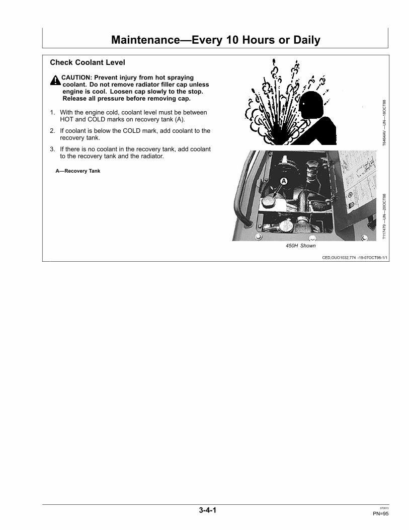
Maintenance—Every 10 Hours or Daily
CED,OUO1032,774 -19-07OCT98-1/1
Check Coolant Level
CAUTION: Prevent injury from hot sprayingcoolant. Do not remove radiator filler cap unlessengine is cool. Loosen cap slowly to the stop.Release all pressure before removing cap.
1. With the engine cold, coolant level must be betweenHOT and COLD marks on recovery tank (A).
2. If coolant is below the COLD mark, add coolant to therecovery tank.
3. If there is no coolant in the recovery tank, add coolantto the recovery tank and the radiator.
A—Recovery Tank
T6464AV—UN—18OCT88
T117479—UN—20OCT98
450H Shown
3-4-1 070813
PN=95
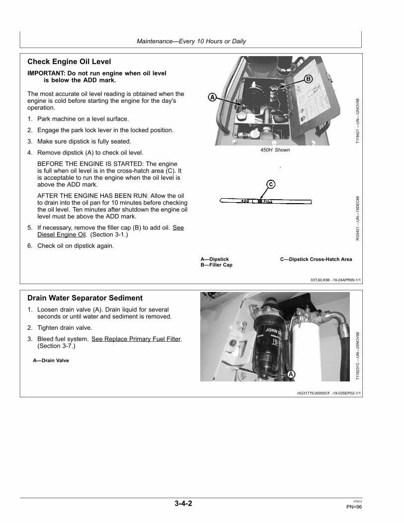
Maintenance—Every 10 Hours or Daily
03T,60,K96 -19-24APR99-1/1
HG31779,00000CF -19-03SEP02-1/1
Check Engine Oil LevelIMPORTANT: Do not run engine when oil level
is below the ADD mark.
The most accurate oil level reading is obtained when theengine is cold before starting the engine for the day'soperation.
1. Park machine on a level surface.
2. Engage the park lock lever in the locked position.
3. Make sure dipstick is fully seated.
4. Remove dipstick (A) to check oil level.
BEFORE THE ENGINE IS STARTED: The engineis full when oil level is in the cross-hatch area (C). Itis acceptable to run the engine when the oil level isabove the ADD mark.
AFTER THE ENGINE HAS BEEN RUN: Allow the oilto drain into the oil pan for 10 minutes before checkingthe oil level. Ten minutes after shutdown the engine oillevel must be above the ADD mark.
5. If necessary, remove the filler cap (B) to add oil. SeeDiesel Engine Oil. (Section 3-1.)
6. Check oil on dipstick again.
T118421—UN—12NOV98
450H Shown
RG5421
—UN—15DEC88
A—DipstickB—Filler Cap
C—Dipstick Cross-Hatch Area
Drain Water Separator Sediment1. Loosen drain valve (A). Drain liquid for several
seconds or until water and sediment is removed.
2. Tighten drain valve.
3. Bleed fuel system. See Replace Primary Fuel Filter.(Section 3-7.)
A—Drain ValveT118231C
—UN—25NOV98
3-4-2 070813
PN=96

Maintenance—Every 10 Hours or Daily
CED,OUO1032,1029 -19-21OCT98-1/1
03T,60,K97 -19-20DEC94-1/1
Check Hydraulic Oil LevelIMPORTANT: DO NOT operate engine without
oil in reservoir.
1. Park machine on level surface and lower allequipment to ground.
2. Turn key switch to “Off”.
3. The hydraulic oil reservoir, fill port and sight glassare located on the right side of machine. Oil must bebetween ADD and FULL marks in sight glass tube (A).
4. If necessary, remove cap and add oil to fill port (B).See Transmission and Hydraulic Oil. (Section 3-1.)
5. Check O-ring on cap before installing.
A—Sight Glass Tube B—Fill Port
T117862B
—UN—26OCT98
T117860B
—UN—26OCT98
Check Transmission Oil Level1. Park machine on level ground.
2. Turn key switch to “Off”.
3. The transmission oil reservoir, fill port and sight glassare located on the left side of the machine. Oil mustbe within the ADD mark and FULL mark on sight glasstube (A).
4. If necessary, add oil to fill port (B). See Transmissionand Hydraulic Oil. (Section 3-1.)
5. Check O-ring on cap before installing.
A—Sight Glass Tube B—Fill Port
T117861B
—UN—26OCT98
T117892B
—UN—26OCT98
3-4-3 070813
PN=97

Maintenance—Every 10 Hours or Daily
CED,OUO1032,1032 -19-14JAN08-1/1
CED,OUO1032,1123 -19-02NOV98-1/1
Clean Dust Unloader ValveIMPORTANT: A missing, damaged or hardened dust
unloader valve will make engine air screenineffective, causing very short element life. Valveshould suck closed above 1/3 engine speed.
It is not necessary to remove engine side shield to cleandust unloader valve. The valve can be accessed throughservice panel in hood.
Squeeze dust valve (A) to remove dust from air cleaner.
If operating in high dust conditions, clean dust valve everycouple of hours of operation to release dust.
A—Dust Valve
T117894B
—UN—03NOV98
Hood and Side Shield Removed for Clarity of Photo
Lubricate Dozer Linkage and Blade SocketT118192B
—UN—12NOV98
Eight Points
T118190B
—UN—12NOV98
Four Points
T118191B
—UN—12NOV98
Two Points
T158711B
—UN—28AUG02
Two Points
Using a grease gun, lubricate each grease fitting untilgrease escapes at joints. See Grease. (Section 3-1.)
3-4-4 070813
PN=98
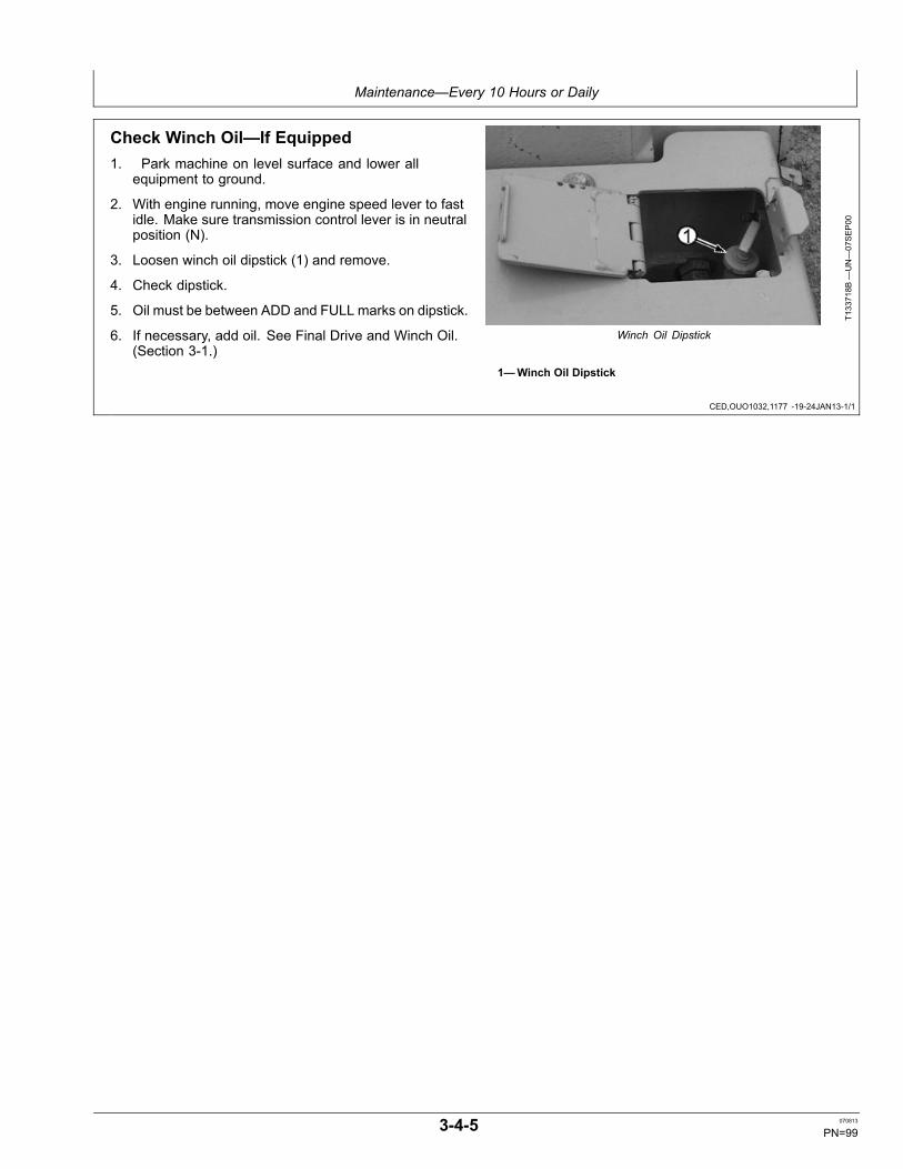
Maintenance—Every 10 Hours or Daily
CED,OUO1032,1177 -19-24JAN13-1/1
Check Winch Oil—If Equipped1. Park machine on level surface and lower all
equipment to ground.
2. With engine running, move engine speed lever to fastidle. Make sure transmission control lever is in neutralposition (N).
3. Loosen winch oil dipstick (1) and remove.
4. Check dipstick.
5. Oil must be between ADD and FULL marks on dipstick.
6. If necessary, add oil. See Final Drive and Winch Oil.(Section 3-1.)
T133718B
—UN—07SEP00
Winch Oil Dipstick
1—Winch Oil Dipstick
3-4-5 070813
PN=99

Maintenance—After 100 Hours
HG31779,000008C -19-28MAY02-1/1
Change Engine Break-In Oil and Filter1. Run engine to warm oil. Stop engine.
2. Remove cap screws and remove oil pan access cover(located below engine).
3. Remove drain plug or open drain valve, if equipped,and allow oil to drain into a container. Dispose ofwaste oil properly.
4. Install drain plug.
5. Remove oil filter (A).
6. Apply thin film of oil to gasket of new filter.
7. Install new filter. Turn filter clockwise by hand untilgasket touches mounting surface.
8. Tighten 1/2 turn more.
9. Fill engine with oil. See Diesel Engine Oil. (Section3-1.).
SpecificationEngine Oil (IncludingFilter)—Capacity................................................14 L (15 qt) Approximate
T117875B
—UN—03NOV98
A—Oil Filter
10. Run engine for 2 minutes and then stop engine. Checkfor leaks around filter and drain plug. Tighten enoughonly to stop leaks.
11. Check oil level.
3-5-1 070813
PN=100

Maintenance—Every 250 Hours
CED,OUO1032,1173 -19-03SEP02-1/1
CED,OUO1032,1034 -19-05FEB13-1/1
HG31779,00000F8 -19-11SEP02-1/1
Drain Final Fuel Filter Sediment1. Loosen drain valve (A). Drain liquid for several
seconds or until water and sediment is removed.
2. Tighten drain valve.
3. Bleed fuel system. See Replace Final Fuel Filter.(Section 3-7.)
A—Drain Valve
T117912B
—UN—02NOV98
Check Final Drives Oil Level1. Park machine on a level surface and turn engine off.
2. Remove oil level and filler plug (A). Oil MUST be within13 mm (0.5 in.) of bottom of filler hole.
IMPORTANT: Avoid overheating and damage tocomponents. Do not overfill final drives.
3. Add oil if needed. See Final Drive and Winch Oil.(Section 3-1.)
4. Install plug.
A—Filler Plug
T117889B
—UN—03NOV98
Right Side Shown
Change Engine Oil and Filter (450H, 550HEarlier Machines and All 650H Machines)1. Run engine to warm oil. Stop engine.
2. Remove cap screws and remove oil pan access cover(located below engine).
3. Remove drain plug or open drain valve, if equipped,and allow oil to drain into a container. Dispose ofwaste oil properly.
4. Install drain plug.
5. Remove oil filter (A).
6. Apply thin film of oil to gasket of new filter.
7. Install new filter. Turn filter clockwise by hand untilgasket touches mounting surface.
8. Tighten 1/2 turn more.
9. Fill engine with oil. See Diesel Engine Oil. (Section3-1.)
SpecificationEngine Oil (IncludingFilter)—Capacity................................................14 L (15 qt) Approximate
T117875B
—UN—03NOV98
A—Oil Filter
10. Run engine for 2 minutes and then stop engine. Checkfor leaks around filter and drain plug. Tighten enoughonly to stop leaks.
11. Check oil level.
3-6-1 070813
PN=101

Maintenance—Every 500 Hours
HG31779,00000F7 -19-11SEP02-1/1
03T,80,K91 -19-05FEB13-1/1
Change Engine Oil and Filter (450H, 550HLater Machines)1. Run engine to warm oil. Stop engine.
2. Remove cap screws and remove oil pan access cover(located below engine).
3. Remove drain plug or open drain valve, if equipped,and allow oil to drain into a container. Dispose ofwaste oil properly.
4. Install drain plug.
5. Remove oil filter (A).
6. Apply thin film of oil to gasket of new filter.
7. Install new filter. Turn filter clockwise by hand untilgasket touches mounting surface.
8. Tighten 1/2 turn more.
9. Fill engine with oil. See Diesel Engine Oil. (Section3-1.)
SpecificationEngine Oil (IncludingFilter)—Capacity................................................14 L (15 qt) Approximate
T117875B
—UN—03NOV98
A—Oil Filter
10. Run engine for 2 minutes and then stop engine. Checkfor leaks around filter and drain plug. Tighten enoughonly to stop leaks.
11. Check oil level.
Check Air Intake Hose1. Check hose (A) for cracks.
2. Check for loose hose clamps.
3. Replace damaged or missing parts.
A—Hose
T118663B
—UN—02DEC98
Turbocharged Engine Shown
3-7-1 070813
PN=102

Maintenance—Every 500 Hours
CED,OUO1032,1124 -19-28AUG02-1/1
Replace Final Fuel Filter1. Turn retaining ring (A) counterclockwise and remove
filter element (B). Allow sediment to drain into acontainer.
NOTE: Dispose of waste properly.
2. Remove fuel drain knob (C) from filter element andinstall on new filter.
3. Clean filter base (D).
NOTE: Do not attempt to turn filter element into base.
4. Install new fuel element by aligning vertical locators(F) into slots (E) on filter base. Push filter element upfirmly until filter snaps against base.
5. Turn retaining ring clockwise into filter base untilretaining ring clicks tightly into place.
6. Loosen bleed screw (G) by turning knobcounterclockwise.
7. Operate primer lever (H) until fuel flow from bleedscrew is free of air bubbles.
NOTE: If there is no fuel flow, push primer lever up andturn crankshaft using start motor to repositioncamshaft. Repeat step 6.
8. Tighten bleed screw.
9. Push primer lever up as far as possible.
A—Retaining RingB—FilterC—Drain KnobD—Filter Base
E—SlotsF—Vertical LocatorsG—Bleed ScrewH—Primer Lever
T117912C
—UN—11NOV98
T7896A
J—UN—25NOV92
T118083B
—UN—11NOV98
3-7-2 070813
PN=103

Maintenance—Every 500 Hours
CED,OUO1032,1135 -19-04NOV98-1/2
CED,OUO1032,1135 -19-04NOV98-2/2
Replace Primary Fuel Filter1. Thoroughly clean primary fuel filter and water
separator assembly and surrounding area.
2. Connect a drain line (A) to filter drain adapters anddrain all fuel from filters.
3. Firmly grasp the retaining ring and rotate itcounterclockwise 1/4 turn. Remove ring with filterelement (B).
4. Inspect filter mounting base for cleanliness. Clean asrequired.
5. Remove water separator bowl (C). Drain and cleanseparator bowl. Dry with compressed air.
6. Install water separator bowl onto new filter element.Tighten securely.
NOTE: The fuel filter must be indexed properly andthe key on canister must be oriented in slot ofmounting base for correct installation.
7. Thoroughly inspect filter base seal ring. Replace asneeded.
8. Install new filter element onto mounting base andposition element using a slight rocking motion. Besure element is properly indexed on mounting base.
T118016B
—UN—11NOV98
A—Drain LineB—Filter Element
C—Separator BowlD—Air Bleed Vent Screw
9. Install retaining ring onto mounting base and tightenabout 1/3 turn until ring “snaps” into the detent. DONOT overtighten the retaining ring.
10. Open air bleed vent screw (D) two full turns by hand.
11. Pump the hand primer (C) on fuel filter until anoticeable amount of fuel and air comes out of ventopening. Continue pumping and close vent screwwhen fuel starts to flow.
12. Pump the hand primer several times until resistance isfelt. Continue pumping and open air bleed vent screwagain.
13. Close air bleed vent screw and pump the hand primerseveral times until resistance is felt again.
C—Hand PrimerT118231B
—UN—11NOV98
3-7-3 070813
PN=104

Maintenance—Every 500 Hours
CED,OUO1040,115 -19-19MAY98-1/1
Check Coolant Conditioner in Radiator
CAUTION: Explosive release of fluids frompressurized cooling system can causeserious burns.
Remove filler cap only when engine is cold orwhen cool enough to touch with bare hands.Slowly loosen cap to first stop to relieve pressurebefore removing completely.
IMPORTANT: John Deere Liquid Coolant Conditionerdoes not protect against freezing. Coolantconditioner prevents rust, scale, andliner cavitation.
NOTE: Check coolant every 500 hours or 6 months,or when replacing 1/3 or more of coolant. Addcoolant conditioner as necessary.
1. Remove radiator cap (A) and test coolant solution.Use one of the following kits to check coolant.
• 3-Way Heavy Duty Coolant Test Kit (TY16175)Coolant test strips provide an effective method tocheck freeze point and additive levels of enginecoolant. See your authorized dealer for 3-Way HeavyDuty Coolant Test Kit and follow instructions on kit.• Coolscan Plus®For a more thorough evaluation of coolant, performCoolscan Plus analysis, where available. See yourauthorized dealer for information about CoolscanPlus.
2. Add TY16004 John Deere Coolant Conditioner orequivalent non-chromate conditioner/rust inhibitoras necessary. Follow instructions on container foramount.
SpecificationCooling System—Capac-ity............................................................................................14 L (15 qt)
3. Install cap.
A—Radiator Cap
TS281—UN—15APR13
T118437—UN—12NOV98
450H Shown
T111110—UN—13AUG97
3-Way Test Kit
T111109—UN—13AUG97
Coolscan Plus
Coolscan Plus is a registered trademark of Deere & Company
3-7-4 070813
PN=105

Maintenance—Every 500 Hours
Continued on next page TX,9015,RB21 -19-14JAN08-1/2
Check Battery Electrolyte Level andTerminals
CAUTION: Battery gas can explode. Keep sparksand flames away from batteries. Use a flashlightto check battery electrolyte level.
Never check battery charge by placinga metal object across the posts. Use avoltmeter or hydrometer.
Always remove grounded (–) battery clampfirst and replace it last.
Sulfuric acid in battery electrolyte ispoisonous. It is strong enough to burn skin,eat holes in clothing, and cause blindnessif splashed into eyes.
Avoid the hazard by:
• Filling batteries in a well-ventilated area.• Wearing eye protection and rubber gloves.• Avoiding breathing fumes when elec-trolyte is added.• Avoiding spilling or dripping electrolyte• Using proper jump start procedure.
If you spill acid on yourself:
1. Flush your skin with water.2. Apply baking soda or lime to help
neutralize the acid.3. Flush your eyes with water for 10—15 minutes.
Get medical attention immediately.
If acid is swallowed:
1. Drink large amounts of water or milk.2. Then drink milk of magnesia, beaten
eggs, or vegetable oil.
TS203—UN—23AUG88
3. Get medical attention immediately.
1. Remove hold-down clamps.
2. Remove battery covers.
3. Clean all excess dirt or debris from top of battery(s)before removing cell caps.
3-7-5 070813
PN=106

Maintenance—Every 500 Hours
TX,9015,RB21 -19-14JAN08-2/2
IMPORTANT: During freezing weather, batteries mustbe charged after water is added to preventbattery freezing. Charge battery using a batterycharger or by running the engine.
4. Fill each cell to within specified range with distilledwater. DO NOT overfill.
CAUTION: Battery gas can explode fromsparks of battery causing personal injury.Always remove grounded (—) battery clampfirst and replace it last.
5. Disconnect battery clamps, grounded clamp first.
6. Clean battery terminals (A) and clamps with a stiffbrush.
7. Apply lubricating grease around battery terminal baseonly.
8. Install and tighten clamps, grounded clamp last.
9. Install hold-down clamps.
A—Battery TerminalB—Fill Tube
C—Electrolyte Level Range
T6996D
B—UN—10FE
B89
Single Level Fill Tube Application
T6996D
A—UN—10FE
B89
Dual Level Fill Tube Application
3-7-6 070813
PN=107

Maintenance—Every 500 Hours
HG31779,00000CE -19-05FEB13-1/1
Replace Winch Oil Filter—If Equipped
T118733B
—UN—03DEC98
Winch Oil Filter Location
T118732C
—UN—16DEC98
Winch Shown Removed for Clarity of Photo
1. The winch oil filter is located on right side betweenwinch and crawler (A).
2. Remove three cap screws from oil filter access cover.
NOTE: The filter canister has a recessed 1/2 in. driveon bottom to assist removal of filter.
3. Remove oil filter access cover.
4. Remove filter (B) by turning counterclockwise.
5. Apply a thin film of oil to gasket of new filter.
6. Install new filter.
7. Install oil filter access cover with three cap screws.
8. Check winch oil. See Check Winch Oil—If Equipped.(Section 3-4.)
T133718E
—UN—30AUG02
Dipstick Fill Port
A—Oil Filter LocationB—Filter
C—Dipstick Fill Port
3-7-7 070813
PN=108

Maintenance—Every 1000 Hours
TX,85,FF1956 -19-28JAN08-1/1
TX,85,RR2733 -19-12JAN93-1/1
Clean Engine Crankcase Ventilation TubeRemove tube (1). Clean and install.
1—Tube
TX1034222A
—UN—08JAN08
Engine Crankcase Tube
Change Final Drives Oil1. Remove drain plug (B) on each side of machine.
2. Drain all oil. Allow oil to drain into a container. Disposeof waste oil properly.
SpecificationFinal Drives Oil (EachSide)—Capacity......................................................................8.5 L (9 qt)
3. Install drain plugs.
4. Remove fill plugs (A).
5. Fill housing with oil until oil flows from fill plug opening.See Final Drive and Winch Oil. (Section 3-1.)
6. Install fill plugs.
A—Fill Plug B—Drain Plug
T117898B
—UN—05NOV98
Right Side Shown
T117889B
—UN—03NOV98
Right Side Shown
3-8-1 070813
PN=109

Maintenance—Every 1000 Hours
Continued on next page CED,OUO1032,783 -19-22JAN03-1/2
Replace Air Cleaner Elements1. On earlier 450H machines: Remove cover by pulling
yellow lever (A) out approximately 13 mm (1/2 in.)and rotating cover counterclockwise approximately25 mm (1 in.).
2. On later 450H machines and all 550H and 650Hmachines: Unfasten latches (A). Remove cover.
A—Air Cleaner Cover ReleaseLever (Earlier 450H)
Latches (550H and 650H)
T118422—UN—12NOV98
Earlier 450H Shown
T120687B
—UN—23MAR99
550H and 650H Shown
3-8-2 070813
PN=110

Maintenance—Every 1000 Hours
CED,OUO1032,783 -19-22JAN03-2/2
CED,OUO1032,1158 -19-14JAN08-1/1
3. Remove primary element (B).
4. Remove secondary element (C).
5. Clean air cleaner housing.
IMPORTANT: Do not install secondaryelement backward.
6. Install new elements. Make sure elements are fullyseated into housing.
7. On 450H machines: Install cover with the dustunloader valve in the 5 o'clock position and yellowlever pulled out. While firmly pushing cover ontohousing, rotate cover clockwise approximately 25 mm(1 in.) until cover snaps into place. Push the yellowlever in to lock.
On 550H and 650H machines: Install cover with thedust unloader valve in the 5 o'clock position. Latchthree latches to secure cover.
B—Primary Element C—Secondary Element
T117903B
—UN—05NOV98
Hood and Side Shields Removed for Clarity of Photo
T117904B
—UN—05NOV98
Hood and Side Shields Removed for Clarity of Photo
Replace Dust Unloader ValveTo remove dust unloader valve, pry collar of unloadervalve (1) from tube of air cleaner housing.
Install new unloader valve by stretching collar over flangeon tube of air cleaner housing. Be sure there are no gapsbetween valve collar and tube.
Valve should remain closed above 1/3 engine speed.
1—Unloader Valve
TX1034224A
—UN—08JAN08
3-8-3 070813
PN=111

Maintenance—Every 1000 Hours
CED,OUO1032,1179 -19-05FEB13-1/1
Drain and Refill Winch Oil and ReplaceFilter—If Equipped
T118733B
—UN—03DEC98
Winch Oil Filter
T118732D
—UN—27APR99
Winch Shown Removed for Clarity of Photo
Winch oil filter (A) is located on right side between winchand crawler .
1. Remove three cap screws from oil filter access cover.
2. Remove oil filter access cover.
3. Remove filter (C) by turning counterclockwise.
4. Remove drain plug (B). Allow oil to drain into container.Dispose of waste properly.
5. Install drain plug.
6. Apply a thin film of oil to gasket of new filter.
7. Install new filter.
8. Fill winch oil reservoir through fill port located at top ofwinch (E) with 34 L (9 gal) of oil. See Final Drive andWinch Oil. (Section 3-1.)
9. Add remaining 4 L (1 gal) of oil through dipstick fillport (D).
10. Check winch oil. See Check Winch Oil—If Equipped.(Section 3-4.)
11. Install oil filter access cover with three cap screws.
A—Oil FilterB—Drain PlugC—Filter
D—Dipstick Fill PortE—Fill Port
T119546B
—UN—14JAN99
Winch Fill Port
T133718D
—UN—29AUG02
Dipstick Fill Port
3-8-4 070813
PN=112

Maintenance—Every 1000 Hours
CED,OUO1047,4 -19-10MAY99-1/1
Clean or Replace Winch Hydraulic BreatherFilter—If EquippedThe breather filter is located in the right servicecompartment.
1. Loosen clamp cap screw.
2. Remove hose (1) from breather filter (2).
3. Using compressed air, clean filter. If filter can not becleaned, replace filter.
4. Install hose end on filter making sure arrow points insame direction (toward reservoir).
5. Tighten clamp (3) with cap screw.
1—Hose2—Breather Filter
3—Clamp
T121231B
—UN—20APR99
550H Shown
3-8-5 070813
PN=113

Maintenance—Every 2000 Hours
CED,OUO1032,1136 -19-14JAN08-1/1
CED,OUO1032,1125 -19-02NOV98-1/3
Continued on next page CED,OUO1032,1125 -19-02NOV98-2/3
Adjust Engine Valve Lash (Clearance)See your authorized dealer.
Change Hydraulic Oil and FilterIMPORTANT: DO NOT operate engine without
oil in reservoir.
1. The hydraulic reservoir, filter and drain are located onright side of machine. Remove fill cap (A).
A—Fill Cap
T117860C
—UN—26OCT98
2. Remove hydraulic drain access panel (A).
3. Attach hose to drain valve (B), if equipped, or removedrain plug and route hose to container. Drain oil.Dispose of waste oil properly.
A—Access Panel B—Drain Valve
T118650B
—UN—02DEC98
450H Shown
T117896B
—UN—05NOV98
Optional Drain Valve Shown
3-9-1 070813
PN=114

Maintenance—Every 2000 Hours
CED,OUO1032,1125 -19-02NOV98-3/3
Continued on next page HG31779,00000D0 -19-06JUN05-1/3
4. Remove filter (A) by turning counterclockwise.
5. Apply thin film of oil to gasket of new filter.
6. Install new filter. Turn filter clockwise by hand untilgasket touches mounting surface.
7. Tighten additional 1/2 turn.
8. Fill reservoir with oil. See Transmission and HydraulicOil. (Section 3-1.)
SpecificationHydraulic OilReservoir—Capacity......................................32 L (8.5 gal) Approximate
9. Check O-ring on fill cap and install fill cap.
10. Start engine and run for 2 minutes. Stop engine andcheck for leaks around filter base. Tighten filter onlyenough to stop leaks.
11. Check oil level in sight tube (B). Oil level must bebetween the ADD and FULL marks on tube. Ifnecessary, add more oil.
T117893B
—UN—03NOV98
A—Filter B—Sight Tube
Change Transmission Oil and Filter1. Transmission hydrostatic reservoir, filter and drain are
located on left side of machine. Remove fill cap (B).
B—Fill Cap
T117892B
—UN—26OCT98
3-9-2 070813
PN=115

Maintenance—Every 2000 Hours
HG31779,00000D0 -19-06JUN05-2/3
HG31779,00000D0 -19-06JUN05-3/3
2. Remove transmission drain access panel (A).
3. Attach hose to drain valve (B), if equipped, or removedrain plug and route hose to container. Drain oil.Dispose of waste oil properly.
4. Put shallow pan on battery cover to prevent oil fromtransmission filter from dripping on battery(ies).
A—Access Panel B—Drain Valve
T118650B
—UN—02DEC98
450H Shown
T117897C
—UN—12NOV98
Optional Drain Valve Shown
5. Remove oil filter (A) by turning counterclockwise.
6. Apply a thin film of oil to gasket of new filter.
7. Install new filter. Turn filter clockwise by hand untilgasket touches mounting surface.
8. Tighten additional 1/2 turn.
9. Fill reservoir with oil. See Transmission and HydraulicOil. (Section 3-1.)
SpecificationTransmission OilReservoir—Capacity............................................................ 53 L (14 gal)
10. Check O-ring on fill cap and install fill cap.
11. Start engine and run for 2 minutes. Stop engine andcheck for leaks around filter base. Tighten filter onlyenough to stop leaks.
12. Check oil level in sight glass tube (B). Oil level shouldbe between the ADD and FULL marks. Add oil ifnecessary.
T117891B
—UN—03NOV98
A—Oil Filter B—Sight Glass
3-9-3 070813
PN=116

Miscellaneous—Machine
CED,OUO1032,781 -19-27JAN00-1/2
CED,OUO1032,781 -19-27JAN00-2/2
Drain the Cooling SystemEvery three years or 3000 hours, if John Deere Coolantis used, drain and flush cooling system using commercialproducts, replace thermostats, and fill with new coolant.
CAUTION: DO NOT remove the radiator fill capunless the engine is cool. Then loosen thecap slowly to the stop. Release all pressurebefore removing the cap.
1. Release pressure and then remove radiator cap (A).
A—Air Screen
T118437—UN—12NOV98
450H Shown
NOTE: Allow coolant to drain into a container. Disposeof waste coolant properly.
2. Open radiator drain valve (A).
3. Open drain valve (B) to drain engine block.
4. Flush system using commercial product.
5. Close all drain valves.
6. Add new coolant. See Diesel Engine Coolant.(Section 3-1.)
A—Radiator Drain Valve B—Engine Drain Valve
T117900B
—UN—05NOV98
T117901B
—UN—05NOV98
4-1-1 070813
PN=117

Miscellaneous—Machine
CED,OUO1032,782 -19-24APR99-1/1
CED,OUO1032,1027 -19-02JUN03-1/1
CED,TX03768,2668 -19-29OCT99-1/1
Fill the Cooling System
CAUTION: DO NOT remove radiator cap unlessengine is cool. Turn the cap slowly to the stop.Release all pressure before removing cap.
With engine COLD, coolant level must be between HOTand COLD marks on recovery tank (A).
If coolant is below COLD mark, add coolant to therecovery tank.
If there is no coolant in recovery tank, add coolant torecovery tank and radiator.
FREEZING TEMPERATURES: Fill with permanent-type,low silicate, ethylene glycol antifreeze (without stop-leakadditive) and clean, soft water. Add TY16004 John DeereCoolant Conditioner or equivalent.
IMPORTANT: Use only permanent-type, low silicate,ethylene glycol base antifreeze in coolantsolution. Other types of antifreeze maydamage cylinder seals.
NOTE: All machines are shipped from the factorywith a 50-50 mixtures (antifreeze and softwater) for protection to –34°C (–30°F).Adjust mixture accordingly to provide freezeprotection for your machine.
TS281—UN—15APR13
T117479—UN—20OCT98
450H Shown
A—Recovery Tank
Clean the Engine Air Precleaner ScreenTo clean the engine air screen (A), remove hose clampand bowl. Shake bowl to remove debris.
IMPORTANT: The engine air screen removes onlypart of the dirt as air goes into the engine. Youmust still clean the air cleaner regularly.
A—Air ScreenT117837B
—UN—21OCT98
Turbocharged Engine Shown
Replace Engine Vibration DamperThe damper assembly is not repairable and should bereplaced every 5 years or 4500 hours, whichever occurs
first, or whenever crankshaft is replaced. See yourauthorized dealer.
4-1-2 070813
PN=118

Miscellaneous—Machine
TX,90,FF3116 -19-03NOV08-1/1
OUT3019,000035F -19-22AUG02-1/1
Do Not Service or Adjust Injection Nozzlesor Injection PumpIf injection nozzles are not working correctly or are dirty,the engine will not run normally. See your authorizeddealer for service.
Changing the injection pump in any way not approved bythe manufacturer will end the warranty. See your copy ofthe John Deere warranty on this machine.
Do not service an injection pump that is not operatingcorrectly. See your authorized injection pump servicecenter.
C-Frame Ball / Blade Socket Joint Adjustment
T158731
4 2
6
1
53
7
T158731—UN—23AUG02
1—Cap Screw (6 used)2—Socket Retainers ( 2 used)
3—Shims (12 included)4—Socket5—Lubrication Fitting
6—Washer (6 used)7—Blade
1. Park machine on level surface. Lower blade to ground.
2. Remove cap screws (1) from socket retainers (2).Remove shims (3).
3. Install ball socket retainers without shims. Measuregap, remove ball socket retainers.
4. Install enough shims to fill gap, plus one extra shim.
5. Install ball socket retainers. Tighten cap screws tospecification.
SpecificationSocket Retainer CapScrews—Torque......................................................... 350 N·m (255 lb-ft)
4-1-3 070813
PN=119

Miscellaneous—Machine
TX03679,00017E3 -19-31MAY01-1/1
T82,EXMA,I -19-19SEP08-1/1
Cleaning Dusty Primary ElementIMPORTANT: A damaged or dirty element may
cause engine damage.
Install new element:
• If the element shows damage andneeds to be replaced.• If element is visibly dirty and will not clean.• After 1000 hours service or annually.
DO NOT clean a secondary element. Install anew element carefully centering it in the canister.
1. Tap element with the palm of your hand, NOT ON AHARD SURFACE.
CAUTION: Prevent possible injury from flyingchips. Reduce compressed air to less than 210kPa (2.1 bar) (30 psi) when using for cleaningpurposes. Clear area of bystanders, guardagainst flying chips, and wear personal protectionequipment including eye protection.
2. If this does not remove dust, use compressed airunder 210 kPa (2.1 bar) (30 psi).
NOTE: Air restriction indicator will not signal correctly ifan element has a break or is not correctly sealedin air cleaner housing. Throw away element thathas the slightest damage. If gasket is brokenor missing, install a new element.
T90684
—UN—10NOV88
T47764
—UN—09NOV88
3. Direct air up and down the pleats from inside tooutside. Be careful not to make a break in the element.
Precautions for Alternator and Regulator
When batteries are connected, follow these rules:
1. Disconnect negative (–) battery cable when you workon or near alternator or regulator.
2. DO NOT TRY TO POLARIZE ALTERNATOR ORREGULATOR.
3. Be sure alternator wires are correctly connectedBEFORE you connect batteries.
4. Do not ground alternator output terminal.
5. Do not disconnect or connect any alternator orregulator wires while batteries are connected or whilealternator is operating.
6. Connect batteries or a booster battery in the correctpolarity (positive [+] to positive [+] and negative [–]to negative [–]).
7. Do not disconnect the batteries when engine isrunning and alternator is charging.
8. Disconnect battery cables before connecting batterycharger to the batteries.
4-1-4 070813
PN=120

Miscellaneous—Machine
Continued on next page TX03679,0001788 -19-29APR11-1/2
Handling, Checking and Servicing BatteriesCarefully
CAUTION: Battery gas can explode. Keep sparksand flames away from batteries. Use a flashlightto check battery electrolyte level.
Never check battery charge by placinga metal object across the posts. Use avoltmeter or hydrometer.
Always remove grounded (-) battery clampfirst and replace it last.
Sulfuric acid in battery electrolyte ispoisonous. It is strong enough to burn skin,eat holes in clothing, and cause blindnessif splashed into eyes.
Avoid the hazard by:
1. Filling batteries in a well-ventilated area.2. Wearing eye protection and rubber gloves.3. Avoiding breathing fumes when
electrolyte is added.4. Avoiding spilling or dripping electrolyte.5. Use proper jump start procedure.
If you spill acid on yourself:
1. Flush your skin with water.2. Apply baking soda or lime to help
neutralize the acid.3. Flush your eyes with water for 15—30 minutes.
Get medical attention immediately.
If acid is swallowed:
1. Do not induce vomiting.2. Drink large amounts of water or milk, but
do not exceed 1.9 L (2 qt).3. Get medical attention immediately.
WARNING: Battery posts, terminals, and relatedaccessories contain lead and lead compounds, chemicalsknown to the State of California to cause cancer andreproductive harm. Wash hands after handling.
If electrolyte spills on the floor, use one of the followingmixtures to neutralize the acid: 0.5 kg (1 lb) baking sodain 4 L (1 gal) water, or 0.47 L (1 pt) household ammonia in4 L (1 gal) water.
TS204—UN—15APR13
TS203—UN—23AUG88
IMPORTANT: Do not overfill the battery cells.
Check the specific gravity of electrolyte in each battery cell.
4-1-5 070813
PN=121
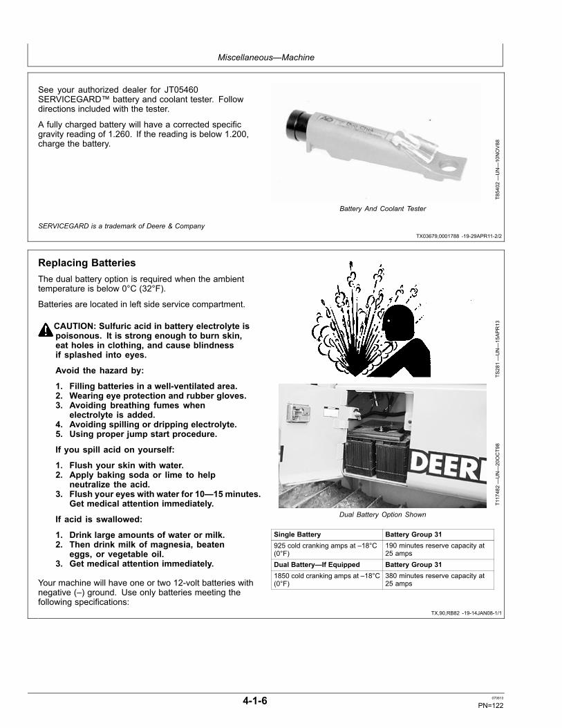
Miscellaneous—Machine
TX03679,0001788 -19-29APR11-2/2
TX,90,RB82 -19-14JAN08-1/1
See your authorized dealer for JT05460SERVICEGARD™ battery and coolant tester. Followdirections included with the tester.
A fully charged battery will have a corrected specificgravity reading of 1.260. If the reading is below 1.200,charge the battery.
T85402
—UN—10NOV88
Battery And Coolant Tester
SERVICEGARD is a trademark of Deere & Company
Replacing BatteriesThe dual battery option is required when the ambienttemperature is below 0°C (32°F).
Batteries are located in left side service compartment.
CAUTION: Sulfuric acid in battery electrolyte ispoisonous. It is strong enough to burn skin,eat holes in clothing, and cause blindnessif splashed into eyes.
Avoid the hazard by:
1. Filling batteries in a well-ventilated area.2. Wearing eye protection and rubber gloves.3. Avoiding breathing fumes when
electrolyte is added.4. Avoiding spilling or dripping electrolyte.5. Using proper jump start procedure.
If you spill acid on yourself:
1. Flush your skin with water.2. Apply baking soda or lime to help
neutralize the acid.3. Flush your eyes with water for 10—15 minutes.
Get medical attention immediately.
If acid is swallowed:
1. Drink large amounts of water or milk.2. Then drink milk of magnesia, beaten
eggs, or vegetable oil.3. Get medical attention immediately.
Your machine will have one or two 12-volt batteries withnegative (–) ground. Use only batteries meeting thefollowing specifications:
TS281—UN—15APR13
T117482—UN—20OCT98
Dual Battery Option Shown
Single Battery Battery Group 31925 cold cranking amps at –18°C(0°F)
190 minutes reserve capacity at25 amps
Dual Battery—If Equipped Battery Group 311850 cold cranking amps at –18°C(0°F)
380 minutes reserve capacity at25 amps
4-1-6 070813
PN=122

Miscellaneous—Machine
TX,90,RB83 -19-14JAN08-1/1
Removing Batteries
CAUTION: Never check battery charge byplacing a metal object across the posts. Usea voltmeter or hydrometer.
Always remove grounded (–) battery clampfirst and replace it last.
1. Turn battery disconnect switch to “Off”.
2. Remove battery cover.
3. Disconnect negative battery cable(s) first then positive(+) cable(s).
4. Remove nuts to remove hold down frame(s).
5. Lift out battery/batteries.
6. Check cables and clamps for damage and wear.
7. Make certain that the battery/batteries are fullycharged.
8. Set the battery/batteries in the compartment makingsure they are level.
9. Install hold down frames.
10. Connect cables; positive then negative.
11. Install battery cover.
12. Turn battery disconnect switch to ON.
TS204—UN—15APR13
T117482—UN—20OCT98
Dual Battery Option Shown
4-1-7 070813
PN=123

Miscellaneous—Machine
Continued on next page CED,OUO1032,1064 -19-24APR99-1/2
Fuse Specifications for ROPS Units (Earlier Machines)
T121137—UN—23APR99
4-1-8 070813
PN=124

Miscellaneous—Machine
CED,OUO1032,1064 -19-24APR99-2/2
F1— 10A Start FuseF2— 5A Fuel Shut-Off FuseF3— 15A Start Aid FuseF4— 10A Horn Fuse
F5— 10A Transmission ControllerFuse
F6— 10A Monitor/Gauge FuseF13— 15A Auxiliary Lights
F14— 15A Auxiliary LightsF15— 15A Heater FuseF16— 20A Light Circuit Breaker
F19— 10A Service Expert FuseK2—Accessory Relay #1
IMPORTANT: Install fuse with correct amperagerating to prevent electrical system damagefrom overload.
The fuse block is located on right side of machine throughfuse panel access cover.
4-1-9 070813
PN=125

Miscellaneous—Machine
Continued on next page HG31779,00000AE -19-16JUL02-1/2
Fuse Specifications for ROPS Units (Later Machines)
10A START
10A HORN
20A ROPS HEATER
20A CB LIGHTS
10A SPARE
7.5A MONITOR
10A TRANS CONTROLLER
10A FUEL SHUT OFF (650)
5A ENG. CONTROLLER (ECU) SWITCHED
10A SPARE/FUEL FILTER HEATER
15A START AID/ ALTERNATOR
ACC RELAY
#1
10A SERVICE EXPERT
ACC RELAY
#3
15A SPARE
HORN RELAY
TRANS CONTROLLER/
MONITOR RELAY
ECU UNSWITCHED POWER FUSE LOCATED
BY ALTERNATOR
F21
T145426
F1
F4
F15
F16
F14
F23
F5
F6
F2
F3
F20
F13
K3
K7
K8
F19
K2T145426—19—06FE
B02
4-1-10 070813
PN=126

Miscellaneous—Machine
HG31779,00000AE -19-16JUL02-2/2
F1 — 10A Start FuseF2— 15A Spare/Fuel Filter
Heater FuseF3— 15A Start Aid/Alternator
Excitation FuseF4 — 10A Horn FuseF5— 10A Transmission
Controller Fuse
F6— 7.5A Monitor/Gauge FuseF13— 15A Spare Fuse (Auxiliary
Light)F14— 10A Spare FuseF15 — 20A Rops (Under Seat)
Heater FuseF16— 20A Light Circuit Breaker
F19— 10A Service Expert FuseF20— 20A Engine Controller
Switched Power FuseF21— 15A Engine Controller
Unswitched Power Fuse (Located By Alternator)
F23— 10A Fuel Shut-Off Fuse(650H)
K2— Accessory Relay #1K3— Accessory Relay #3K7— Horn RelayK8— Transmission
Controller/Monitor Relay
IMPORTANT: Install fuse with correct amperagerating to prevent electrical system damagefrom overload.
The fuse block is located on right side of machine throughfuse panel access cover.
4-1-11 070813
PN=127

Miscellaneous—Machine
Continued on next page CED,OUO1032,1065 -19-24APR99-1/2
Fuse Specifications for Cab Units—If Equipped (Earlier Machines)
T121389—UN—11MAY
99
4-1-12 070813
PN=128

Miscellaneous—Machine
CED,OUO1032,1065 -19-24APR99-2/2
F1— 10A Start FuseF2— 5A Fuel Shut-Off FuseF3— 15A Start Aid FuseF4— 10A Horn FuseF5— 10A Transmission Controller
FuseF6— 10A Monitor/Gauge FuseF7— 15A Heater Blower Fuse
F8— 15A Condenser Fan FuseF9— 15A Condenser Fan FuseF10— 5A A/C Compressor Fuse
(S.N. —874114); 10A A/CCompressor Fuse (S.N.874115— )
F11— 15A Front/Rear Wiper Fuse
F12— 15A Left/Right Wiper FuseF13— 15A Auxiliary LightsF14— 15A Auxiliary LightsF15— 15A Heater FuseF16— 20A Light Circuit BreakerF17— 10A Dome Light, Radio
Fuse
F18— 10A Radio Fuse(Unswitched)
F19— 10A Service Expert FuseK2—Accessory Relay #1K4—Heater Blower RelayK5—A/C RelayK6—Accessory Relay #2
IMPORTANT: Install fuse with correct amperagerating to prevent electrical system damagefrom overload.
The fuse block is located on right side of machine throughfuse panel access cover.
4-1-13 070813
PN=129
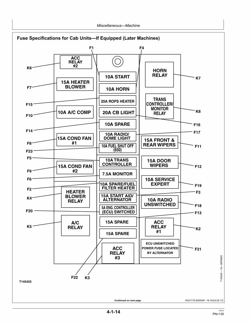
Miscellaneous—Machine
Continued on next page HG31779,00000AF -19-16JUL02-1/2
Fuse Specifications for Cab Units—If Equipped (Later Machines)
15A HEATER BLOWER
10A A/C COMP
HEATER BLOWER
RELAY
15A COND FAN #1
15A COND FAN #2
A/C RELAY
10A START
10A HORN
20A ROPS HEATER
20A CB LIGHT
10A SPARE
10A RADIO/ DOME LIGHT
10A FUEL SHUT OFF (650)
5A ENG. CONTROLLER (ECU) SWITCHED
7.5A MONITOR
10A SPARE/FUEL FILTER HEATER
15A START AID/ ALTERNATOR
ACC RELAY
#1
HORN RELAY
15A DOOR WIPERS
15A FRONT & REAR WIPERS
10A TRANS CONTROLLER
10A SERVICE EXPERT
10A RADIO UNSWITCHED
TRANS CONTROLLER/
MONITOR RELAY
ACC RELAY
#3
15A SPARE
15A SPARE
ACC RELAY
#2
ECU UNSWITCHED
POWER FUSE LOCATED
BY ALTERNATOR
K6
F1 F4
F15
F7
F10
F8
F9
K4
K5
F14
F23
F5
F6
K7
K8
F11
F12
F19
F18
K2
F3
F17
F16
F2
F20
F22 K3
F13
T145425
F21
T145425—19—06FE
B02
4-1-14 070813
PN=130

Miscellaneous—Machine
HG31779,00000AF -19-16JUL02-2/2
03T,55,K88 -19-24APR99-1/1
F1— 10A Start FuseF2— 10A Spare/Fuel Filter Heater
FuseF3— 15A Start Aid FuseF4— 10A Horn FuseF5— 10A Transmission Controller
FuseF6— 7.5A Monitor/Gauge FuseF7— 15A Heater Blower FuseF8— 15A Condenser Fan Fuse #1
F9— 15A Condenser Fan Fuse #2F10— 10A A/C Compressor FuseF11— 15A Front/Rear Wiper FuseF12— 15A Left/Right Door Wiper
FuseF13— 15A Spare Fuse (Auxiliary
Light)F14— 10A Start Aid FuseF15— 15A Rops (Under Seat)
Heater Fuse
F16— 20A Light Circuit BreakerF17— 10A Dome Light, Radio
FuseF18— 10A Radio Fuse
(Unswitched)F19— 10A Service Expert FuseF20— 5A Engine Controller Fuse
(Switched Power)F21— 15A Engine Controller
Fuse (Unswitched Power)(Located By Alternator)
F22— 15A Spare FuseF23— 10A Fuel Shut Off Fuse
(650H)K3—Accessory Relay #3K4—Heater Blower RelayK5—A/C RelayK7—Horn RelayK8—Transmission Con-
troller/Monitor Relay
IMPORTANT: Install fuse with correct amperagerating to prevent electrical system damagefrom overload.
The fuse block is located on right side of machine throughaccess cover.
Drain Fuel Tank Sump
CAUTION: Handle fuel carefully. Shut the engineOFF. Do not smoke while you work on fuel system.
1. Remove rear access panel (A).
2. Remove left fuel sump access panel (B). If equippedwith winch, remove both left and right fuel sumpaccess panels.
3. Attach hose to drain cock (C) and route through sumpopening. Open drain cock for several seconds to drainwater and sediment.
4. Close drain cock. Replace fuel sump panel(s) andtighten cap screws.
5. Install rear access panel, if removed. Tighten capscrews.
A—Rear Access PanelB—Left Fuel Sump Access
Panel
C—Drain Cock
T117851B
—UN—26OCT98
650H Shown
T117852B
—UN—26OCT98
Left Fuel Sump Access Panel
T117853B
—UN—26OCT98
4-1-15 070813
PN=131

Miscellaneous—Machine
CED,OUO1032,1138 -19-18FEB08-1/1
CED,OUO1032,1403 -19-24APR99-1/1
Cleaning Fresh Cab Air Filter—If Equipped1. Loosen wing nuts (A) to remove access cover.
2. Remove filter holder from compartment. Remove filterelement.
3. Tap filter on flat surface with dirty side down to loosenand remove large portions of dirt.
4. Install filter. Tighten wing nuts.
A—Wing Nuts (2 used)
T118218B
—UN—11NOV98
T120688B
—UN—23MAR99
Cleaning Cab Air Recirculation Filter—IfEquipped1. Pull latch holding filter in place.
2. Remove filter (A).
3. Use compressed air under 210 kPa (2.1 bar) (30 psi).Direct air opposite to normal air flow.
4. Wash filter in warm, soapy water, rinse and dry.
5. If filter will not come clean, replace as necessary.
6. Fasten latch.
A—FilterT120689B
—UN—23MAR99
4-1-16 070813
PN=132

Miscellaneous—Machine
CED,OUO1032,1175 -19-27APR99-1/1
Check Air Conditioner Refrigerant Level—IfEquippedIMPORTANT: Prevent possible compressor damage. If
receiver/dryer moisture eye color indicates "wet"(pink), dryer is saturated and should be changedwithin the next 100 machine hours to preventfurther buildup of moisture in refrigerant.
1. Remove left side access cover of air conditioningcompartment.
2. Using a mirror (A), check color of sight glass (B) to seeif receiver/dryer is wet (pink) or dry (blue).
3. If wet (pink), see your authorized dealer within the next100 machine hours to service receiver/dryer.
T121303B
—UN—03MAY
99
A—Mirror B—Sight Glass
4-1-17 070813
PN=133

Miscellaneous—Machine
TX,90,RR2516 -19-10JAN12-1/1
Track Sag General InformationProperly adjusted tracks prolong chain life. To get themaximum life out of track bushings, keep the track sagproperly adjusted. Improperly adjusted track wears at amore rapid rate.
A tight track causes higher loading which will increasewear on the pins, bushings, links, sprocket and front idler.The graph (A) shows how the loading on the track chainincreases significantly when tracks are too tight. Also,a tight track requires more horsepower, increasing fuelconsumption and decreasing productivity.
Periodically check track sag. In some applications, tracksmay require adjustment several times during a workingday. This is especially true when working in differentconditions on the same job site, as moisture content ofthe soil changes.
Tracks should always be adjusted in the actual operatingconditions. If material packs in the undercarriage, thetracks should be adjusted with the material packed in thecomponents.
When packing occurs, track sag is taken up and mustbe loosened to extend wear life. The track spring willrecoil and the machine will continue to operate with tighttrack. However, continued operation without looseningthe tracks will result in excessive pin and bushing wear,sprocket popping, tooth tip wear, and excessive loads onthe entire undercarriage and final drive system.
With sealed chain, internal pin and bushing wear createssag which reduces the effects of packing. However, if asealed chain is too tight, accelerated bushing wear occurs.
Lubricated chain is different due to the absence of internalpin and bushing wear. It is absolutely essential to keepsag adjusted to prevent accelerated bushing outsidediameter wear.
Maintaining track sag is very important regardless of thetype of track being used.
T7800A
J—UN—31JU
L92
Track Tension kg (lb) vs. Track Sag mm (in.)
T7800A
H—UN—31JU
L92
Proper Track Sag
4-1-18 070813
PN=134

Miscellaneous—Machine
CED,OUO1032,1041 -19-14JAN08-1/1
T82,BHMA,K -19-14JAN08-1/1
CED,OUO1032,787 -19-02JUN03-1/1
Adding Oil to the RollerNOTE: Rollers are serviced off of the machine.
1. Remove plug (B) from roller.
2. Rotate plug opening to 45° angle.
3. Fill roller with oil until the oil starts to drip out. SeeTrack Rollers, Front Idler and Carrier Roller Oil.(Section 3-1.)
4. Apply pipe sealant or TEFLON® tape to new plug.Install plug.
B—Plug
T113532—UN—17FE
B98
TEFLON is a registered trademark of Du Pont Co.
Do Not Service Control Valves and CylindersSpecial tools and information are needed to servicecontrol valves and cylinders.
If these parts need service, see your authorized dealer.
Adjusting Engine Speed Control LeverTension (Earlier Machines)1. Open the left rear service door.
2. Adjust lock nut (A) until a minimum of 31—40 N (7—9lb) force is required to initiate movement in the forwarddirection using a spring scale placed just below theknob of the lever.
A—Lock Nut
T117999B
—UN—24NOV98
T118767—UN—11DEC98
4-1-19 070813
PN=135

Miscellaneous—Machine
CED,OUO1032,788 -19-07OCT98-1/1
TX,90,RB48 -19-03DEC97-1/1
Checking Neutral Start System
CAUTION: Avoid possible injury or death. Besure all people are away from machine whenneutral start checks are performed.
1. Move FNR lever to N.
2. Move park lock lever to down (unlocked) position (A).
3. Turn key switch to “Start” position. Starter must notengage. If engine starts, see your authorized dealer.
4. Move park lock lever to up (locked) position (B).
5. Turn key switch to “Start” position. Starter shouldengage. If engine does not start, see your authorizeddealer.
6. Move FNR lever to F or R.
7. Turn key switch to “Start” position. Starter must notengage.
8. Move FNR lever to N.
9. Turn key switch to “Start” position. Starter shouldengage. If starter does not engage, see yourauthorized dealer.
A—Unlocked Position B—Locked Position
T118001B
—UN—11NOV98
T118007C
—UN—14JAN99
Keep ROPS Installed ProperlyMake certain all parts are reinstalled correctly if theroll-over protective structure (ROPS) is loosened orremoved for any reason. Tighten mounting bolts (A) toproper torque.
SpecificationROPS MountingBolts—Torque............................................................. 624 N·m (460 lb-ft)
The protection offered by the ROPS will be impaired if theROPS is subjected to structural damage, is involved inan overturn incident, or is in any way altered by welding,bending, drilling, or cutting. A damaged ROPS should bereplaced, not reused.
A—Bolts
T117812B
—UN—20OCT98
Front ROPS Mounting Bolt
T117813B
—UN—20OCT98
Rear ROPS Mounting Bolt
4-1-20 070813
PN=136

Miscellaneous—Machine
TX,90,FF1972 -19-24APR99-1/2
TX,90,FF1972 -19-24APR99-2/2
T82,SKMA,AT -19-01AUG94-1/1
Checking Track Shoe Cap Screw TorqueTrack shoe bolt torque should be periodically checked.If the cap screws do not meet the minimum torquespecifications, remove the shoes and clean the matingsurfaces of the shoes and links before tightening the bolts.
Specification450H and 550HTrack Shoe MinimumChecking—Torque...................................... 305 ± 14 N·m (225 ± 10 lb-ft)650H TrackShoe MinimumChecking—Torque...................................... 380 ± 14 N·m (280 ± 10 lb-ft)
If unit is operated with loose track shoes, the cap screwholes in the shoes and links will wallow out and it may bedifficult to keep the track shoes tight. Loose shoes canalso cause hardware failure and loss of track shoes.
Install all track shoe nuts with rounded edges against thelink and chamfered edges away from the link. Be sure nutis properly positioned in the link so there is full contactarea between the nut and the link.
A—Rounded edge B—Chamfered edge
T6009A
N—UN—09FE
B89
T6794A
M—UN—23FE
B89
IMPORTANT: Tighten cap screws to torquespecification using a criss-cross pattern.Then repeat torque pattern again.
Tighten cap screws using torque-turn torque method.Track Shoes—Specification
450H and 550H TrackShoe Cap Screw (9/16in.)—Torque....................................................... 88 N·m (65 lb-ft) Second
Pass—Additional 1/3 (120° ) turn650H Track Shoe CapScrew (5/8 in.)—Torque................................. 163 N·m (120 lb-ft) Second
Pass—Additional 1/3 (120° ) turn450H and 550H MasterSplit Link Cap Screw(9/16 in.)—Torque.............................................. 88 N·m (65 lb-ft) Second
Pass—Additional 1/3 (120°) turn650H Master SplitLink Cap Screw (5/8in.)—Torque................................................... 163 N·m (120 lb-ft) Second
Pass—Additional 1/2 (180°) turn
T6352A
H—UN—23FE
B89NOTE: Replacement hardware should be lubricated
and tightened to above specification.
Hardware Torque SpecificationsCheck cap screws and nuts to be sure they are tight.If hardware is loose, tighten to torque shown on thefollowing charts unless a special torque is specified.
4-1-21 070813
PN=137

Miscellaneous—Machine
DX,TORQ1 -19-12JAN11-1/1
Unified Inch Bolt and Screw Torque ValuesTS1671 —UN—01MAY03
SAE Grade 1 SAE Grade 2a SAE Grade 5, 5.1 or 5.2 SAE Grade 8 or 8.2Bolt or ScrewSize Lubricatedb Dryc Lubricatedb Dryc Lubricatedb Dryc Lubricatedb Dryc
N·m lb.-in. N·m lb.-in. N·m lb.-in. N·m lb.-in. N·m lb.-in. N·m lb.-in. N·m lb.-in. N·m lb.-in.1/4 3.7 33 4.7 42 6 53 7.5 66 9.5 84 12 106 13.5 120 17 150
N·m lb.-ft. N·m lb.-ft.5/16 7.7 68 9.8 86 12 106 15.5 137 19.5 172 25 221 28 20.5 35 26
N·m lb.-ft. N·m lb.-ft.3/8 13.5 120 17.5 155 22 194 27 240 35 26 44 32.5 49 36 63 46
N·m lb.-ft. N·m lb.-ft. N·m lb.-ft.7/16 22 194 28 20.5 35 26 44 32.5 56 41 70 52 80 59 100 74
N·m lb.-ft.1/2 34 25 42 31 53 39 67 49 85 63 110 80 120 88 155 1159/16 48 35.5 60 45 76 56 95 70 125 92 155 115 175 130 220 1655/8 67 49 85 63 105 77 135 100 170 125 215 160 240 175 305 2253/4 120 88 150 110 190 140 240 175 300 220 380 280 425 315 540 4007/8 190 140 240 175 190 140 240 175 490 360 615 455 690 510 870 6401 285 210 360 265 285 210 360 265 730 540 920 680 1030 760 1300 960
1-1/8 400 300 510 375 400 300 510 375 910 670 1150 850 1450 1075 1850 13501-1/4 570 420 725 535 570 420 725 535 1280 945 1630 1200 2050 1500 2600 19201-3/8 750 550 950 700 750 550 950 700 1700 1250 2140 1580 2700 2000 3400 25001-1/2 990 730 1250 930 990 730 1250 930 2250 1650 2850 2100 3600 2650 4550 3350
Torque values listed are for general use only, based on the strength of the boltor screw. DO NOT use these values if a different torque value or tighteningprocedure is given for a specific application. For plastic insert or crimped steeltype lock nuts, for stainless steel fasteners, or for nuts on U-bolts, see thetightening instructions for the specific application. Shear bolts are designed to failunder predetermined loads. Always replace shear bolts with identical grade.
Replace fasteners with the same or higher grade. If highergrade fasteners are used, tighten these to the strength of theoriginal. Make sure fastener threads are clean and that youproperly start thread engagement. When possible, lubricateplain or zinc plated fasteners other than lock nuts, wheel boltsor wheel nuts, unless different instructions are given for thespecific application.
aGrade 2 applies for hex cap screws (not hex bolts) up to 6 in. (152 mm) long. Grade 1 applies for hex cap screws over 6in. (152 mm) long, and for all other types of bolts and screws of any length.b“Lubricated” means coated with a lubricant such as engine oil, fasteners with phosphate and oil coatings, or 7/8 in.and larger fasteners with JDM F13C, F13F or F13J zinc flake coating.c“Dry” means plain or zinc plated without any lubrication, or 1/4 to 3/4 in. fasteners with JDM F13B, F13E or F13H zinc flake coating.
4-1-22 070813
PN=138

Miscellaneous—Machine
DX,TORQ2 -19-12JAN11-1/1
Metric Bolt and Screw Torque ValuesTS1670 —UN—01MAY03
4.84.8 8.8 9.8 10.9 12.9 12.9
12.912.910.99.88.84.8
Class 4.8 Class 8.8 or 9.8 Class 10.9 Class 12.9Bolt or ScrewSize Lubricateda Dryb Lubricateda Dryb Lubricateda Dryb Lubricateda Dryb
N·m lb.-in. N·m lb.-in. N·m lb.-in. N·m lb.-in. N·m lb.-in. N·m lb.-in. N·m lb.-in. N·m lb.-in.M6 4.7 42 6 53 8.9 79 11.3 100 13 115 16.5 146 15.5 137 19.5 172
N·m lb.-ft. N·m lb.-ft. N·m lb.-ft. N·m lb.-ft.M8 11.5 102 14.5 128 22 194 27.5 243 32 23.5 40 29.5 37 27.5 47 35
N·m lb.-ft. N·m lb.-ft. N·m lb.-ft.M10 23 204 29 21 43 32 55 40 63 46 80 59 75 55 95 70
N·m lb.-ft.M12 40 29.5 50 37 75 55 95 70 110 80 140 105 130 95 165 120M14 63 46 80 59 120 88 150 110 175 130 220 165 205 150 260 190M16 100 74 125 92 190 140 240 175 275 200 350 255 320 235 400 300M18 135 100 170 125 265 195 330 245 375 275 475 350 440 325 560 410M20 190 140 245 180 375 275 475 350 530 390 675 500 625 460 790 580M22 265 195 330 245 510 375 650 480 725 535 920 680 850 625 1080 800M24 330 245 425 315 650 480 820 600 920 680 1150 850 1080 800 1350 1000M27 490 360 625 460 950 700 1200 885 1350 1000 1700 1250 1580 1160 2000 1475M30 660 490 850 625 1290 950 1630 1200 1850 1350 2300 1700 2140 1580 2700 2000M33 900 665 1150 850 1750 1300 2200 1625 2500 1850 3150 2325 2900 2150 3700 2730M36 1150 850 1450 1075 2250 1650 2850 2100 3200 2350 4050 3000 3750 2770 4750 3500
Torque values listed are for general use only, based on the strength ofthe bolt or screw. DO NOT use these values if a different torque value ortightening procedure is given for a specific application. For stainless steelfasteners or for nuts on U-bolts, see the tightening instructions for thespecific application. Tighten plastic insert or crimped steel type lock nutsby turning the nut to the dry torque shown in the chart, unless differentinstructions are given for the specific application.
Shear bolts are designed to fail under predetermined loads. Alwaysreplace shear bolts with identical property class. Replace fasteners withthe same or higher property class. If higher property class fasteners areused, tighten these to the strength of the original. Make sure fastenerthreads are clean and that you properly start thread engagement. Whenpossible, lubricate plain or zinc plated fasteners other than lock nuts,wheel bolts or wheel nuts, unless different instructions are given for thespecific application.
a“Lubricated” means coated with a lubricant such as engine oil, fasteners with phosphate and oil coatings, or M20and larger fasteners with JDM F13C, F13F or F13J zinc flake coating.b“Dry” means plain or zinc plated without any lubrication, or M6 to M18 fasteners with JDM F13B, F13E or F13H zinc flake coating.
4-1-23 070813
PN=139

Miscellaneous—Operational Checkout
HG31779,00000D1 -19-03SEP02-1/57
HG31779,00000D1 -19-03SEP02-2/57
Continued on next page HG31779,00000D1 -19-03SEP02-3/57
Operational Checkout
Use this procedure to check all systems and functionson the machine. It is designed so you can make a quickcheck of the operation of the machine while doing awalk-around inspection and performing specific checksfrom the operator's seat.
Should you experience a problem with your machine, youwill find helpful diagnostic information in this checkout thatwill pinpoint the cause. This information may allow youto perfume a simple adjustment which will reduce thedowntime of your machine. Use the table of contents tohelp find adjustment procedures.
The information you provide after completing theoperational checkout will allow you or your authorizeddealer to pinpoint the specific test or repair work neededto restore the machine to design specifications.
A location will be required which is level and has adequatespace to complete the checks. No tools or equipment areneeded to perform the checkout.
Complete the necessary visual checks (oil levels, oilcondition, external leaks, loose hardware, linkage, wiring,etc.) prior to doing the checkout. The machine must be atoperating temperature for many of the checks.
Start at the top of the left column and read completelydown the column before performing check, follow thissequence from left to right. In the far right column, if noproblem is found (OK), you will be instructed to go tonext check. If a problem is indicated (NOT OK), you willbe referred to either a section in this manual, or to yourauthorized dealer.
Cooling System Checks
Radiator Cap, CoolantLevel, Coolant ConditionChecks
CAUTION: Explosive release of fluids from pressurized coolingsystem can cause serious burns. DO NOT remove radiator capunless engine is cool. Then turn cap slowly to the stop. Releaseall pressure before you remove cap.
Open radiator cap.LISTEN: If radiator is warmer than air temperature, a "whoosh" must be heard whenradiator cap is opened to first stop position.
OK: Check complete.
FEEL: The radiator cap must have a stop position and must be pushed down to turn toremove.
NOTOK: If vacuum releasevalve is plugged or springcorroded, replace radiatorcap.
Inspect coolant level, coolant condition. NOTOK: If coolant is oily orfoamy, see your authorizeddealer.
LOOK: The radiator cap must have a good seal and gasket. The seal must movefreely and the spring must not be corroded.
NOTOK: If rust in coolant,drain, flush and replacecoolant, see Drain theCooling System. (Section4-1.)
LOOK: The coolant must not be oily, foamy, or rusty. NOTOK: If radiator islow and coolant tank hascoolant in it, check for airleak on recovery hose. Seeyour authorized dealer.
4-2-1 070813
PN=140

Miscellaneous—Operational Checkout
HG31779,00000D1 -19-03SEP02-4/57
HG31779,00000D1 -19-03SEP02-5/57
Continued on next page HG31779,00000D1 -19-03SEP02-6/57
Radiator Outside Air FlowCheck (Blower Fan) CAUTION: Prevent possible injury from unexpected machine
movement. Keep park lock lever in up (locked) position duringthis check to prevent movement of unit.
Start engine. Run at fast idle.FEEL: Air flow must be brisk and even through radiator.NOTE: It is normal to have less air flow at center of fan.Stop engine.Inspect fins for mud and debris.LOOK: Sides of radiator must be free of mud, leaves, grass, and other debris. OK: Check complete.Inspect radiator for bent or damaged fins. NOTOK: Clean outside of
radiator.LOOK: Fins must be straight and not broken or cracked. NOTOK: Straighten fins.
Replace radiator if severelydamaged. See yourauthorized dealer.
Hose, Clamps, and WaterPump Checks
Inspect all radiator and heater hoses for cracks or leaks.
Inspect all hose clamps.Inspect water pump for leaks. OK: Check complete.LOOK: Radiator and heater hoses must NOT be brittle, show signs of leaks, or rubon adjacent parts.
NOTOK: Replacedamaged hoses. See yourauthorized dealer.
LOOK: All hose clamps must be tight and perpendicular to the hose. Crooked clampscan cause damage and leaks.
NOTOK: Straighten andtighten clamps. See yourauthorized dealer.
LOOK: Water pump must NOT show signs of leaks. NOTOK: Replace waterpump. See your authorizeddealer.
Fan Checks
T6558AN —UN—23AUG93
Remove engine side shield.Inspect fan blades for damage.LOOK: Fan blades must not have any nicks or bends.Check fan for correct installation. OK: Check complete.LOOK: Cupped portion of fan blades must be forward from radiator. NOTOK: If blades are
bent, replace fan. If fanblades are nicked, repair.See your authorized dealer.
NOTE: If fan is installed backwards, about 50% of its capacity is lost. NOTOK: Remove andreinstall fan. See yourauthorized dealer.
4-2-2 070813
PN=141

Miscellaneous—Operational Checkout
HG31779,00000D1 -19-03SEP02-7/57
HG31779,00000D1 -19-03SEP02-8/57
Continued on next page HG31779,00000D1 -19-03SEP02-9/57
Fan Shroud and FanGuard Checks
T6488GC —UN—23AUG93
Check fan to fan shroud clearance.Inspect fan guard. OK: Check complete.LOOK: Fan must be centered in fan shroud. NOTOK: Adjust fan shroud
to center fan. See yourauthorized dealer.
LOOK: Guard must NOT be bent or damaged, all mounting brackets must be intactand all hardware must be tight.
NOTOK: Repair or replaceguard. Tighten hardware.See your authorized dealer.
Fan Belt Checks
T118314 —UN—01DEC98
A—Tension Adapter
Inspect condition of belt. Tension adapter (A) will automatically adjust to belt wear.LOOK: There must NOT be any oil or grease on fan belt or pulley.LOOK: Inside surface of belt must NOT have any cracks.Check fan belt for tightness.LOOK: Serpentine belt tension stop on swing arm must NOT contact fixed stops ontensioner (A).
OK: Check complete.
LISTEN: Fan belt must not squeal when engine is stopped. NOTOK: Replace fan belt.See Inspect SerpentineBelt. (Section 3-3.)
Fuel System Checks
4-2-3 070813
PN=142

Miscellaneous—Operational Checkout
HG31779,00000D1 -19-03SEP02-10/57
Continued on next page HG31779,00000D1 -19-03SEP02-11/57
Start Aid Checks
T118188B —UN—02NOV98
T118723B —UN—01DEC98
A—Canister
Open right rear service door.Check position of canister (A) in holder.Inspect plastic line from top of starting aid to air intake manifold.Press and hold starting aid button down to operate starting aid. OK: Check complete.LOOK: There must NOT be any kinks or breaks in line and ends must be installedsecurely.
NOTOK: Can must clickonto solenoid.
Check for dot on ether starting aid nozzle in air intake manifold. NOTOK: Replace plasticline. See your authorizeddealer.
LOOK: Dot must be at the 12 o'clock position on the fitting of air intake manifold. NOTOK: Adjust fitting sodot is in correct position.
Water Separator TrapCheck
T119033B —UN—15DEC98Open rear right side service access door.Loosen drain knob and drain fuel for several seconds or until water and sedimentare removed.
OK: Check complete.
LOOK: Fuel must flow from drain tube. NOTOK: No flow, removeand clean valve. See yourauthorized dealer.
Tighten drain knob. NOTOK: Replace valve.See your authorized dealer.
4-2-4 070813
PN=143

Miscellaneous—Operational Checkout
HG31779,00000D1 -19-03SEP02-12/57
Continued on next page HG31779,00000D1 -19-03SEP02-13/57
Fuel Cap
T118247C —UN—24NOV98Remove fuel cap.NOTE: Air "hiss" from tank is normal when cap is removed.Inspect fuel cap seal. OK: Check complete.LOOK: Seal on fuel cap must NOT be damaged and vents must be open. NOTOK: Replace fuel cap.
Fuel Tank Check
T118247C —UN—24NOV98NOTE: Do this check before you refuel.Remove fuel cap.Use a flashlight and inspect bottom of fuel tank by shining light through the fuel.LOOK: There must NOT be any pieces of debris such as leaves in bottom of fueltank that would restrict fuel flow.
OK: Check complete.
LOOK: Fuel sender ball must be floating on fuel. NOTOK: Remove largepieces of debris throughfiller neck.
4-2-5 070813
PN=144

Miscellaneous—Operational Checkout
HG31779,00000D1 -19-03SEP02-14/57
HG31779,00000D1 -19-03SEP02-15/57
Continued on next page HG31779,00000D1 -19-03SEP02-16/57
Final Fuel Filter Checks
T119041B —UN—15DEC98
T119032B —UN—15DEC98Remove right side engine side shield."Crack" open bleed screw on fuel filter and operate hand primer on fuel transfer pump.LOOK: Fuel must come out of bleed screw when hand primer is operated.Tighten bleed screw of fuel filter and again operate hand primer on fuel pump.FEEL: Resistance must be felt when fuel is being pumped and no resistance will befelt after system is pumped up.
OK: Check complete.
T119034B —UN—15DEC98Turn fuel filter knob to drain sediment.
NOTOK: Be certain fuelfilter is clean. If not, replacefilter and recheck fuelpump. See Replace FinalFuel Filter. (Section 3-7)
Transmission Checks
Park Lock/Neutral StartSwitch and ReverseWarning Alarm Check
NOTE: If park lock lever is down and brake pedal is depressed, engine will start.
Park lock lever down.Turn key switch to “Start” position.LOOK: Brake pedal will move UP and must travel to fullup positionLOOK: Engine must not crank.Park lock lever up and FNR lever in forward.Turn key switch to start position.LOOK: Engine must not crank.Move FNR lever to reverse and key switch to start.LOOK: Engine must not crank and reverse warning alarm must sound. OK: Check complete.Depress brake pedal. NOTOK: See your
authorized dealer.LISTEN: Reverse warning alarm must NOT sound. NOTOK: Reverse warning
alarm continues to sound.See your authorized dealer.
4-2-6 070813
PN=145

Miscellaneous—Operational Checkout
HG31779,00000D1 -19-03SEP02-17/57
HG31779,00000D1 -19-03SEP02-18/57
HG31779,00000D1 -19-03SEP02-19/57
Continued on next page HG31779,00000D1 -19-03SEP02-20/57
Transmission FilterRestriction Indicator,Transmission OilTemperature and ParkBrake Indicator Check
Key switch "On" to bulb check position.
LOOK: Transmission oil filter restriction light, hydraulic oil filter restriction light,transmission oil temperature light, fasten seat belt indicator, and park brake indicator on.Start engine and set at slow idle.LOOK: Transmission oil filter and temperature indicators OFF, park brake indicator on.Lower park brake lever. OK: Check complete.LOOK: Park brake indicator goes OFF. NOTOK: Check bulb
in monitor. See yourauthorized dealer.
Transmission Gauge andCharge Pressure Check
Start engine and position engine speed control lever at slow idle.
LOOK: Needle must be in the green.Slowly increase engine speed to fast idle.LOOK: Needle must gradually rise as speed increases. At fast idle needle must still bein the green with very minimal fluctuation.
OK: Check complete.
NOTE: Transmission oil filter restriction indicator might stay on until oilreaches operating temperature.
NOTOK: See yourauthorized dealer.
Park Brake Valve LeakageCheck
Operate machine for several minutes to heat hydrostatic oil to normal operatingtemperature.Position engine speed control at slow idle with park lock lever UP.LOOK: Observe transmission pressure gauge while moving park lock lever to DOWNposition. Brake pedal will move to full UP position as park brake lever is lowered.LOOK: Pressure should drop as park lock lever is moved DOWN, then return tooriginal value.Depress brake pedal. OK: Check complete.LOOK: Pressure should drop as brake pedal is released, then return to original value. NOTOK: Isolate park
brakes, brake valve tolocate leakage. See yourauthorized dealer.
LOOK: Observe tracks for any creep or movement. NOTOK: Tracks move inneutral, see your authorizeddealer.
Park Brake OperationalCheck CAUTION: Pushing on brake pedal will stop machine abruptly.
Operate machine slowly in forward. Fully depress park brake pedal and then release. OK: Check complete.LOOK: Machine MUST STOP when the pedal is depressed and MUST MOVE whenpedal is released.
NOTOK: See yourauthorized dealer.
4-2-7 070813
PN=146

Miscellaneous—Operational Checkout
HG31779,00000D1 -19-03SEP02-21/57
HG31779,00000D1 -19-03SEP02-22/57
HG31779,00000D1 -19-03SEP02-23/57
Continued on next page HG31779,00000D1 -19-03SEP02-24/57
Steering Checks Transmission speed control at minimum speed position or speed in grip (if equipped)at 1.0.Run engine at approximately 1200 rpm. FNR to forward. Move steer lever or speed ingrip to right hand detent position.LOOK: The right hand track should stop and transmission pressure should remainin the green.Move steer lever to maximum right hand position.LOOK: The right hand track must counter-rotate and transmission pressure shouldremain in the green.
OK: Check complete.
Repeat check for left hand track. NOTOK: If track willnot stop or will notcounter-rotate. See yourauthorized dealer.
NOTE: Steering rate and modulation can be set to operator prefer-ence (Low, Med or High).
StrR (Steer Rate) Setting the machine responsiveness to a change insteering lever movement for right and left steer.
StrM (Steer Modulation) Setting the right and left modulation changes theamount of steering that occurs for a given amount of steering lever movement.
NOTOK: If chargepressure is not in green.See your authorized dealer.
Decelerator Pedal Check Start engine.Park lock lever down.Depress decelerator pedal.Move engine speed control lever to fast idle.Transmission speed control at maximum speed or speed in grip (if equipped) to 3.0.FNR in forward.Release decelerator pedal.LOOK: Machine must accelerate smoothly to maximum speed. OK: Check complete.NOTE: Decelerator response time can be set to operator preference. NOTOK: If engine speed
increases and deceleratorpedal moves up, see yourauthorized dealer.
FNR Check Engine speed at 1500 rpm. Transmission speed control at position 1 1/2 or speed ingrip (if equipped) to 2.0. Make several shifts from neutral to forward, neutral to reverseand then forward to reverse.
SpecificationEngine—Speed.................................................................................................1500 rpmLOOK: Observe how both tracks start to increase in speed. Both tracks must start atthe same time and machine should move forward or reverse in a straight line.
OK: Check complete.
NOTE: FNR shift rate can be set to operator preference. Low has a slowerreaction time and high has a quicker reaction time.
NOTOK: See yourauthorized dealer.
Multi-Function ReliefValve Check (ClosedLoop System Relief Valve)
Engine at fast idle.
Transmission speed at 2 1/2 position or speed in grip (if equipped) to 2.5.Machine at operating temperature.Place machine under heavy load with blade.LOOK: Machine must push straight and tracks maintain same speed. OK: Check complete.LISTEN: Engine must not cycle as heavy load is pushed. NOTOK: See your
authorized dealer.
4-2-8 070813
PN=147

Miscellaneous—Operational Checkout
HG31779,00000D1 -19-03SEP02-25/57
HG31779,00000D1 -19-03SEP02-26/57
HG31779,00000D1 -19-03SEP02-27/57
Continued on next page HG31779,00000D1 -19-03SEP02-28/57
Battery Disconnect Switch, Key Switch, Display Monitor, Battery, And Hour Meter Checks
Battery DisconnectSwitch Check
T118722B —UN—01DEC98NOTE: Disconnect switch is located on left side of machine through
the battery access door.Turn battery disconnect switch OFF.Turn key switch "On". OK: Check battery
disconnect switch. Seeyour authorized dealer.
LOOK: Do indicator lights illuminate? NOTOK: Continue check.Turn battery disconnect switch ON.Turn key switch "On", but do not start engine. OK: Go to next check.LOOK: Do indicator lights illuminate? NOTOK: Check battery
disconnect switch. Seeyour authorized dealer.
Hour Meter Circuit Check
T118152B —UN—30OCT98Earlier Machine Shown
Start engine.LOOK: Hour meter must be rotating after 1/10 hour.Stop engine, turn key switch “On”. OK: Go to next check.LOOK: Hour meter must not rotate. NOTOK: See your
authorized dealer.
Work Light Check Key switch "On". OK: Go to next check.Push work light switch on. NOTOK: Replace bulbs.LOOK: Both front work lights and rear light must come on. NOTOK: Check wiring.
See your authorized dealer.
4-2-9 070813
PN=148

Miscellaneous—Operational Checkout
HG31779,00000D1 -19-03SEP02-29/57
Continued on next page HG31779,00000D1 -19-03SEP02-30/57
Front/Rear Wiper andWasher Motor Check—IfEquipped
T119018B —UN—14DEC98
A—Front/Rear Wiper Rocker Switch
Key switch “On”.Push rocker switch (A) to first detent, middle position.LOOK: Both front/rear wiper motors should operate.Push rocker switch all the way in and hold. OK: Go to next check.LOOK: Both front/rear wiper motors and washer motor should operate. NOTOK: Check fuse. See
your authorized dealer.
Left/Right Wiper andWasher Motor Check—IfEquipped
T119018B —UN—14DEC98
B—Left/Right Wiper Rocker Switch
Key switch “On”.Push rocker switch (B) to first detent, middle position.LOOK: Both left/right wiper motors should operate.Push rocker switch all the way in and hold. OK: Go to next check.LOOK: Both left/right wiper motors and washer motor should operate . NOTOK: Check fuse. See
your authorized dealer.
4-2-10 070813
PN=149
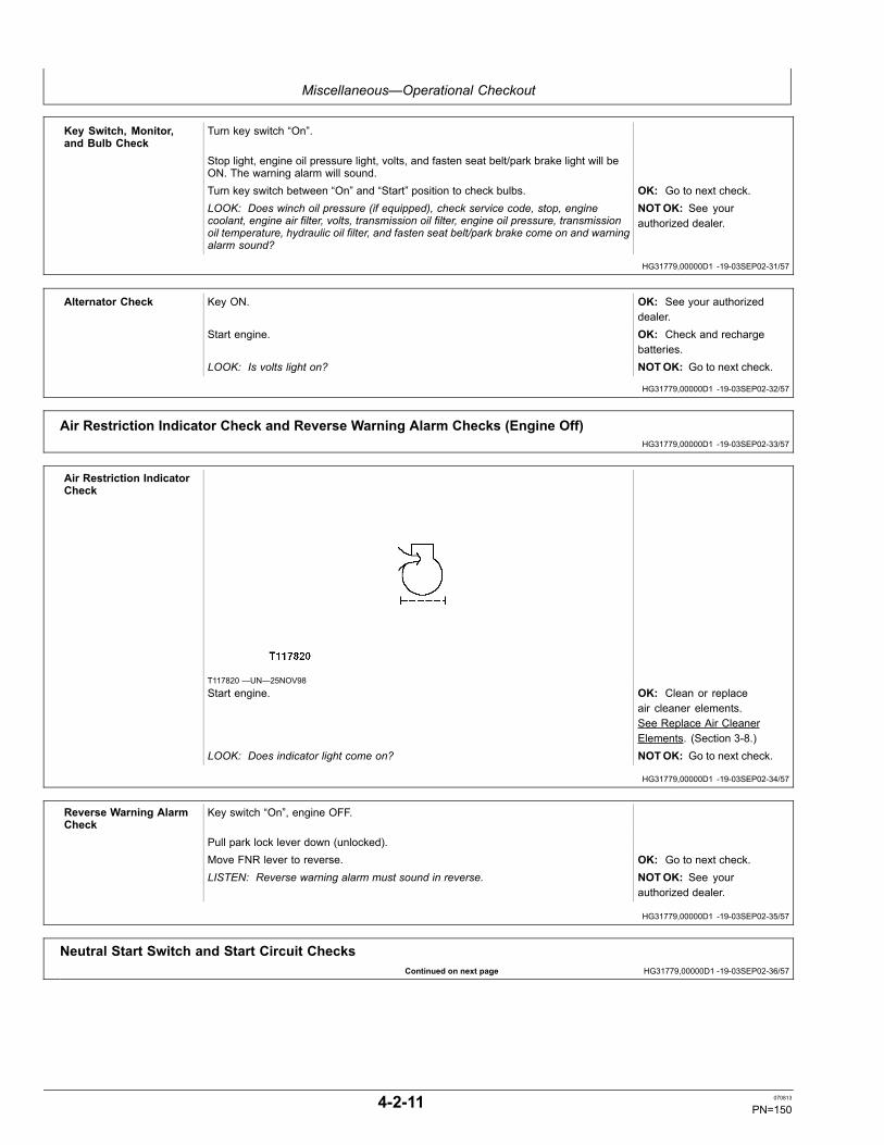
Miscellaneous—Operational Checkout
HG31779,00000D1 -19-03SEP02-31/57
HG31779,00000D1 -19-03SEP02-32/57
HG31779,00000D1 -19-03SEP02-33/57
HG31779,00000D1 -19-03SEP02-34/57
HG31779,00000D1 -19-03SEP02-35/57
Continued on next page HG31779,00000D1 -19-03SEP02-36/57
Key Switch, Monitor,and Bulb Check
Turn key switch “On”.
Stop light, engine oil pressure light, volts, and fasten seat belt/park brake light will beON. The warning alarm will sound.Turn key switch between “On” and “Start” position to check bulbs. OK: Go to next check.LOOK: Does winch oil pressure (if equipped), check service code, stop, enginecoolant, engine air filter, volts, transmission oil filter, engine oil pressure, transmissionoil temperature, hydraulic oil filter, and fasten seat belt/park brake come on and warningalarm sound?
NOTOK: See yourauthorized dealer.
Alternator Check Key ON. OK: See your authorizeddealer.
Start engine. OK: Check and rechargebatteries.
LOOK: Is volts light on? NOTOK: Go to next check.
Air Restriction Indicator Check and Reverse Warning Alarm Checks (Engine Off)
Air Restriction IndicatorCheck
T117820 —UN—25NOV98Start engine. OK: Clean or replace
air cleaner elements.See Replace Air CleanerElements. (Section 3-8.)
LOOK: Does indicator light come on? NOTOK: Go to next check.
Reverse Warning AlarmCheck
Key switch “On”, engine OFF.
Pull park lock lever down (unlocked).Move FNR lever to reverse. OK: Go to next check.LISTEN: Reverse warning alarm must sound in reverse. NOTOK: See your
authorized dealer.
Neutral Start Switch and Start Circuit Checks
4-2-11 070813
PN=150
Miscellaneous—Operational Checkout
HG31779,00000D1 -19-03SEP02-37/57
HG31779,00000D1 -19-03SEP02-38/57
Continued on next page HG31779,00000D1 -19-03SEP02-39/57
Neutral Start SwitchCheck
Park lock lever down.
Move FNR to NEUTRAL.Apply brakes.Turn key to START position. OK: If machine starts, go
to next check.LISTEN: Does machine start? NOTOK: If machine
does not start, see yourauthorized dealer.
Park lock lever UP.Move FNR to neutral.Turn key to start position. OK: If machine starts, go
to next check.LISTEN: Does machine start? NOTOK: If machine
does not start, see yourauthorized dealer.
Pull park lock lever UP.Move FNR to forward or reverse.Turn key to start position. OK: If starting motor does
not operate, go to nextcheck.
LISTEN: Starting motor MUST NOT operate. NOTOK: If startingmotor operates, see yourauthorized dealer.
Pull park lock lever DOWN.Move FNR to forward or reverse.Turn key to start position. OK: If machine does not
start, go to next check.LISTEN: Does machine start? NOTOK: If machine starts,
see your authorized dealer.
Start Circuit Check Park lock lever UP and FNR in NEUTRAL. OK: Go next check.Turn key to “Start” position. NOTOK: Starting motor
did not turn. See yourauthorized dealer.
LISTEN: Starting motor must operate. NOTOK: Oil Pressureindicator stays on formore than 3 seconds afterstart-up. Stop engine andcheck oil level. See CheckEngine Oil Level. (Section3-4.)
LISTEN: Engine must start. NOTOK: Starting motorturns, but engine does notstart. See your authorizeddealer.
LOOK/LISTEN: During engine cranking, on monitor indicator all monitor functionsmust be ON and alarm must BEEP. On gauge package, low voltage and engine oilpressure indicators must be ON, fuel gauge needles moves to full and other gaugeneedles move slightly.
NOTOK: See yourauthorized dealer.
Hydraulic System Checks
4-2-12 070813
PN=151

Miscellaneous—Operational Checkout
HG31779,00000D1 -19-03SEP02-40/57
HG31779,00000D1 -19-03SEP02-41/57
HG31779,00000D1 -19-03SEP02-42/57
Continued on next page HG31779,00000D1 -19-03SEP02-43/57
Visual Check Park machine on level surface.Lower all equipment to ground.LOOK: Hydraulic oil must be visible in sight glass located inside right rear access door. OK: Go to next check.LOOK: Hydraulic lines and fitting must not seep or leak oil. NOTOK: Add oil. See
Change Hydraulic Oil andFilter. (Section 3-9.)
LOOK: Cylinder seals must not seep or leak oil. NOTOK: Repair leaks.See your authorized dealer.
Drift Check Operate engine at slow idle.Place dozer blade 50 mm (2 in.) from ground. OK: Go to next check.LOOK: Blade must NOT touch ground within two minutes. NOTOK: Determine if
drift is excessive foryour operation, see yourauthorized dealer.
Control Valve LiftCheck Test
T6583AE —UN—23AUG93
Raise dozer approximately 305 mm (1.0 ft) above ground.Stop engine.Pull blade lever control lever.LOOK: Blade must not lower.Start engine and raise front of machine, tilt full right. Stop engine.Push blade level control lever to power down position and tilt right.LOOK: Machine must not lower.Start engine and tilt blade full left. Stop engine.Push blade level control lever to tilt left. OK: Go to next check.LOOK: Machine must not lower. NOTOK: Inspect lift
check in valve. See yourauthorized dealer.
Blade Float Check Raise front of crawler off of ground with blade.Push blade level control lever into float detent.LOOK: Front of crawler must lower to ground. OK: Go to next check.FEEL: Blade level control lever must stay in float detent position. NOTOK: Inspect and
repair valve detents. Seeyour authorized dealer.
4-2-13 070813
PN=152

Miscellaneous—Operational Checkout
HG31779,00000D1 -19-03SEP02-44/57
HG31779,00000D1 -19-03SEP02-45/57
HG31779,00000D1 -19-03SEP02-46/57
Continued on next page HG31779,00000D1 -19-03SEP02-47/57
Hydraulic PumpPerformance Check
T6583AE —UN—23AUG93
Hydraulic oil must be at operating temperature 66°C (150°F).Operate engine at slow idle.Place blade on ground. OK: Go to next check.Record time required to raise blade. NOTOK: Check oil level
and condition. SeeCheck Hydraulic Oil Level.(Section 3-4.)
LOOK: Maximum cycle time 7.5 seconds. NOTOK: See yourauthorized dealer.
Undercarriage Checks
Track Sag Roller and IdlerLeakage Checks
T119010 —UN—14DEC98Measure track sag at longest span of unsupported track.LOOK: Track sag must be 51 ± 6 mm (2 ± 1/4 in.). OK: Go to next check.Inspect rollers and front idler. NOTOK: Adjust track sag.
See Adjust Track Sag.(Section 3-3.)
LOOK: No oil seepage must be noted from roller or idlers. NOTOK: Repair or replaceroller or idler. See yourauthorized dealer.
Grouser Wear, BentTrack Shoe, and LooseHardware Checks
Inspect for worn grousers, bent track shoes and loose shoe hardware.
LOOK: Grouser bars must NOT be worn excessively and track shoes must NOT bebent and hardware must be tight.
OK: Go to next check.
NOTE: Excessive grouser wear weakens track shoes and may re-sult in track shoes bending.
NOTOK: If shoe hardwareis loose, remove shoe andclean joint before tightening.See Checking Track ShoeCap Screw Torque. (Section4-1.)
4-2-14 070813
PN=153
Miscellaneous—Operational Checkout
HG31779,00000D1 -19-03SEP02-48/57
HG31779,00000D1 -19-03SEP02-49/57
HG31779,00000D1 -19-03SEP02-50/57
HG31779,00000D1 -19-03SEP02-51/57
Continued on next page HG31779,00000D1 -19-03SEP02-52/57
Track Roller Check Have another person operate machine in forward direction. OK: Go to next check.LOOK: All rollers must turn but must NOT "wobble". NOTOK: Repair. See your
authorized dealer.
Accessory Checks
Seat Control Checks Does seat raise and lower easily?Does seat angle change easily?Does lever unlock easily and then lock to hold seat and consoles in position?Does lever move easily to unlock seat support?Does seat move forward and rearward easily?Does lever lock seat support in position when released?Does seat back tilt forward and rearward easily?Does lever unlock and lock easily to hold seat back in position? OK: Go to next check.See Adjusting the Seat. (Section 2-1.) NOTOK: Inspect linkage
and repair. Go to yourauthorized dealer.
Visual Inspection of AllLines and Hoses
Engine OFF.
Inspect all lines and hoses.Are lines and hoses straight, NOT kinked or worn from rubbing on other machine partsor "weather checked"?Are hose and line connections clean, NOT showing signs of leakage, such as oil ordust accumulation at fittings?
OK: Check complete.
All hose and line clamps must be in place and tight. Clamps must have rubber insertsor cushions in place to prevent clamps from crushing or wearing into hoses or lines?
NOTOK: Reposition hosesor lines and tighten orreplace clamps. Tightenfittings or replace O-rings infittings. Replace hoses orlines as required. See yourauthorized dealer.
Air ConditionerCompressor Check—IfEquipped
Inspect compressor and belt.
LOOK: Is drive belt tight?LOOK: Is belt in good condition, NOT frayed, worn or glazed?LOOK: Are compressor mounting brackets in good condition, and bracket cap screwstight?LOOK: Is belt pulley in good condition, NOT worn or groved?LOOK: Are electrical connections to compressor clutch clean and tight? Is wiring tocompressor in good condition?Turn fan ON to check for interference to shroud due to damaged fan blades.Check wiring harness system for damage or cuts.LISTEN: Is there any noise of fan blades to shroud? OK: Check complete.LOOK: Are air conditioner hoses protected by cordura sleeves in engine compartmentnext to fan shroud and alternator area?
NOTOK: Repair or replacecomponents as required.See your authorized dealer.
4-2-15 070813
PN=154
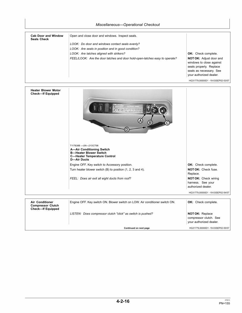
Miscellaneous—Operational Checkout
HG31779,00000D1 -19-03SEP02-53/57
HG31779,00000D1 -19-03SEP02-54/57
Continued on next page HG31779,00000D1 -19-03SEP02-55/57
Cab Door and WindowSeals Check
Open and close door and windows. Inspect seals.
LOOK: Do door and windows contact seals evenly?LOOK: Are seals in position and in good condition?LOOK: Are latches aligned with strikers? OK: Check complete.FEEL/LOOK: Are the door latches and door hold-open-latches easy to operate? NOTOK: Adjust door and
windows to close againstseals properly. Replaceseals as necessary. Seeyour authorized dealer.
Heater Blower MotorCheck—If Equipped
T117838B —UN—21OCT98
A—Air Conditioning SwitchB—Heater Blower SwitchC—Heater Temperature ControlD—Air Ducts
Engine OFF. Key switch to Accessory position. OK: Check complete.Turn heater blower switch (B) to position (1, 2, 3 and 4). NOTOK: Check fuse.
Replace.FEEL: Does air exit all eight ducts from roof? NOTOK: Check wiring
harness. See yourauthorized dealer.
Air ConditionerCompressor ClutchCheck—If Equipped
Engine OFF. Key switch ON. Blower switch on LOW. Air conditioner switch ON. OK: Check complete.
LISTEN: Does compressor clutch "click" as switch is pushed? NOTOK: Replacecompressor clutch. Seeyour authorized dealer.
4-2-16 070813
PN=155

Miscellaneous—Operational Checkout
HG31779,00000D1 -19-03SEP02-56/57
HG31779,00000D1 -19-03SEP02-57/57
Air Conditioner Check—IfEquipped
T117838B —UN—21OCT98
A—Air Conditioning SwitchB—Heater Blower SwitchC—Heater Temperature ControlD—Air Ducts
Start engine and run at fast idle.Turn air conditioner switch (A) to ON position. On position is up (Snow Flake). Positiondown (Cactus) is not used.Turn heater blower switch (B) to position “4”.Wait for any warm air in duct system to dissipate. OK: Check complete.FEEL: Is air from ducts cool? NOTOK: See your
authorized dealer.
Service Decal Check
T118210B —UN—03NOV98Check service decal on inside of engine hood door. OK: Operational Checkout
completed.LOOK: Service decal must be legible. NOTOK: Replace decal.
4-2-17 070813
PN=156

Miscellaneous—Troubleshooting
HG31779,0000020 -19-06MAY10-1/1
Troubleshooting ProcedureNOTE: Troubleshooting charts are arranged from the
simplest to verify, to least likely, more difficultto verify. When diagnosing a problem, useall possible means to isolate the problem to asingle component or system. Use the followingsteps to diagnose problems:
Step 1. Operational Checkout Procedure
Step 2. Troubleshooting Charts
Step 3. Adjustments
Step 4. See your authorized John Deere dealer.
4-3-1 070813
PN=157

Miscellaneous—Troubleshooting
Continued on next page HG31779,00000D2 -19-03SEP02-1/3
EngineSymptom Problem Solution
Engine Will Not Start or Starts Hard FNR lever not in neutral Move FNR lever to neutral.
Battery disconnect switch off Turn switch on.
Fuel shut off Open fuel shut-off valve.
Fuel tank empty Check fuel quantity.
Fuel tank vent plugged Remove cap and listen to sound of airentering tank. Replace cap.
No electrical power to injection pumpsolenoid
Turn key switch to ON position. Musthear click at injection pump. See yourauthorized dealer.
Water in fuel or water frozen in fuel line Drain water from fuel filter(s). Changefilter(s). Inspect fuel filter(s) for water.
Debris in fuel or wrong grade of fuel Check fuel/water separator for debris.Check fuel grade.
Air leak on suction side of fuel system Check for bubbles in fuel filter andtighten connections. Inspect fuel linesfor damage. See your authorizeddealer.
Fuel transfer pump diaphragm leaking Check engine oil for fuel dilution.
Slow cranking speed Check battery and connections.
Restricted air filter Check air filter restriction indicatorlight and air filters.
Fuel tank shut-off not fully open Open fuel tank shut-off.
Valve clearance Check and adjust valves.
Engine Surges or Stalls Frequently Air in fuel Inspect filter for evidence of air in fuel.Tighten connections and bleed fuelsystem.
Fuel partially shut off Open fuel shut-off valve.
Fuel tank vent plugged Remove cap and listen to sound of airentering tank. Replace cap.
Debris in fuel or wrong grade of fuel Check fuel/water separator for debris.Check fuel grade.
Water in fuel Drain water from fuel filter(s). Changefilter(s).
4-3-2 070813
PN=158

Miscellaneous—Troubleshooting
Continued on next page HG31779,00000D2 -19-03SEP02-2/3
Symptom Problem Solution
Fuel filter plugged Replace filter(s).
Engine Misses Air in fuel Check for evidence of air in filter.Tighten connections and bleed fuelsystem.
Fuel partially shut off Open fuel shut-off valve.
Debris in fuel or wrong fuel grade Check fuel filter(s) for debris. Clean.Check grade of fuel.
Engine Does Not Develop FullPower
Fuel partially shut off Open fuel shut-off valve.
Fuel filter clogged Replace fuel filter(s).
Wrong grade of fuel Drain and add correct fuel.
Air system restricted Check air filter restriction indicator andair filters.
Incorrect high idle speed (too low)(Earlier Machines)
Linkage out of adjustment. Adjust.See your authorized dealer.
Engine Emits Excessive Black orGray Exhaust Smoke
Restricted air filter Check air filter restriction indicator andair filters. Replace.
Incorrect grade of fuel Use correct grade of fuel.
Engine Emits Excessive Blue orWhite Smoke
Cranking speed too slow Check batteries and connections.
Incorrect grade of fuel Use correct grade of fuel.
Engine running too cold Check thermostat operation. See yourauthorized dealer.
Slow Acceleration Improper fuel Use correct grade of fuel.
Abnormal Engine Noise Low or incorrect engine oil Add correct oil to proper level.
Loose or worn hydraulic pump Inspect. See your authorized dealer.
Engine oil diluted Inspect engine oil. Determine cause.
Low Oil Pressure (Oil PressureLight On, Red STOP IndicatorFlashing)
Low oil level Add oil to proper level. Inspect engineoil.
Wrong viscosity oil/oil diluted withdiesel fuel
Change oil.
Engine Overheats (Engine CoolantIndicator and Red STOP IndicatorFlashing)
Low coolant level Fill cooling system and check for leaks.
Low engine oil level Add oil.
4-3-3 070813
PN=159

Miscellaneous—Troubleshooting
HG31779,00000D2 -19-03SEP02-3/3
Symptom Problem Solution
Loose or broken fan belt Tighten or replace belt.
Fan on backwards Check for correct fan installation.
Radiator dirty or plugged Check air flow. Clean radiator.
Radiator shroud missing or damaged Inspect. Repair or replace.
Engine overloaded Reduce load.
Wrong fuel Use correct grade of fuel.
Radiator cap Replace cap.
Thermostat missing, cooling systemcoated with lime deposits
Flush cooling system. See yourauthorized dealer.
Excessive Fuel Consumption Air system restricted Check filter restriction indicator andair filters. Replace.
Leakage in fuel system Inspect. Repair.
Incorrect grade of fuel Drain and fill with correct fuel.
Operator holding hydraulics in reliefmode
Return control levers to neutralposition.
4-3-4 070813
PN=160

Miscellaneous—Troubleshooting
Continued on next page HG31779,00000D3 -19-15JAN08-1/2
Electrical SystemSymptom Problem Solution
Starter Will Not Crank Engine Battery disconnect switch turned off Turn switch on.
Starter Listen for click from starter solenoid. Ifclick is heard, the starter control circuitis functioning. If click is not heard, seeyour authorized dealer.
Starter relay With vehicle in neutral, open rightengine service door and listen forclick from starter relay when the keyswitch is in START position. If click isheard, the key switch, circuit breaker,start fuse connectors, and neutralstart switch are functioning and thestarter relay, relay ground, or starter isdefective. See your authorized dealer.
Starter Solenoid Chatters Poor or corroded connections atbattery, battery ground strap, or starter
Inspect, clean, and tighten ifnecessary.
Engine Cranks Slowly Loose or corroded battery cables Inspect and clean or tighten.
Loose battery ground cable Open battery cover and inspect andtighten battery ground cable.
Excessive engine load Change engine oil to proper grade fortemperature.
Starter Continues to Run Starter solenoid stuck Shut engine off. See your authorizeddealer.
Starter relay stuck on Shut engine off. See your authorizeddealer.
Battery Uses Too Much Water Cracked battery case Replace battery.
High ambient temperature Fill with distilled water.
Cracked Battery Case No battery hold down clamp Replace battery and install hold downclamp.
Loose battery hold down clamp Replace battery and install hold downclamp.
Battery hold down clamp too tight Replace battery and install batteryhold down clamp correctly.
Frozen battery Keep battery fully charged in coldweather.
Low Battery Output Low water level Add distilled water.
4-3-5 070813
PN=161

Miscellaneous—Troubleshooting
HG31779,00000D3 -19-15JAN08-2/2
Symptom Problem Solution
Dirty or wet battery top causingdischarge
Clean and wipe battery top dry.
Corroded or loose battery cables Clean and tighten battery cables.
Broken battery post Wiggle battery post by hand. If postwiggles or turns, replace battery.
Charge Indicator and Low OilPressure Indicator Stays On withKey Off
Broken ground wire to alternator Inspect and repair.
Worn alternator Repair or replace alternator.
Voltage Indicator Light (RemainsOn with Engine Running)
Loose or glazed belt. Engine rpm low Check belt. Replace if glazed. Raiseengine rpm above 1200 rpm. If lightremains on, see your authorizeddealer.
Diode or phase winding Increase engine rpm to fast idle. Iflight goes out or gets dim, it indicatesa defective diode or phase winding.See your authorized dealer.
Loose or corroded electricalconnections on battery, ground strap,starter, or alternator
Inspect, clean, or tighten electricalconnections.
Alternator Light Out, but LowCharging System Voltage
Indicator light bulb Inspect and replace.
Loose wiring connector Inspect and repair.
Noisy Alternator Worn or defective bearings inalternator
Remove belt and feel for roughbearing while turning alternator pulley.
Drive belt Inspect and replace if necessary.
Pulley not aligned Inspect.
4-3-6 070813
PN=162

Miscellaneous—Troubleshooting
HG31779,00000D4 -19-14JAN08-1/1
Hydraulic SystemSymptom Problem Solution
Blade Lifts and/or Blade Tilts TooSlowly
Cold oil Allow oil to warm up.
Oil viscosity too high (too thick) Use correct oil.
Control valve linkage Inspect linkage. Repair or adjust. Seeyour authorized dealer.
Worn hydraulic pump Check blade raise cycle time.
Blade Fails to Lift and Blade Failsto Tilt
Low hydraulic oil level Check. Add hydraulic oil.
Blade Hard to Control Front idler vertical movementexcessive
Adjust front idler to side frameclearance.
Pump Excessively Noisy Cold oil Allow unit to warm up.
Low oil level Check, add oil.
Oil viscosity too high (oil too thick) Change oil to correct viscosity oil.
Hydraulic Oil Overheats Operator holds control valve open toolong, causing system relief valve toopen
Instruct operator on correct operationof dozer.
Oil viscosity too high (oil too thick) Change oil to correct viscosity.
Hydraulic Oil Foams Water in oil Inspect oil. Change.
Using wrong oil Inspect. Change oil.
4-3-7 070813
PN=163
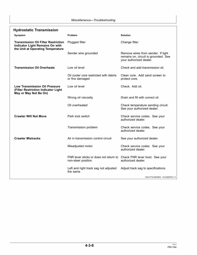
Miscellaneous—Troubleshooting
HG31779,00000D5 -19-03SEP02-1/1
Hydrostatic TransmissionSymptom Problem Solution
Transmission Oil Filter RestrictionIndicator Light Remains On withthe Unit at Operating Temperature
Plugged filter Change filter.
Sender wire grounded Remove wires from sender. If lightremains on, circuit is grounded. Seeyour authorized dealer.
Transmission Oil Overheats Low oil level Check and add transmission oil.
Oil cooler core restricted with debrisor fins damaged
Clean core. Add sand screen toprotect core.
Low Transmission Oil Pressure(Filter Restriction Indicator LightMay or May Not Be On)
Low oil level Check. Add oil.
Wrong oil viscosity Drain and fill with correct oil.
Oil overheated Check temperature sending circuit.See your authorized dealer.
Crawler Will Not Move Park lock switch Check service codes. See yourauthorized dealer.
Transmission problem Check service codes. See yourauthorized dealer.
Crawler Mistracks Air in transmission control circuit See your authorized dealer.
Misadjusted motor Check service codes. See yourauthorized dealer.
FNR lever sticks or does not return tonon-steer position
Check FNR lever boot. See yourauthorized dealer.
Left and right track sag not adjustedthe same
Adjust track sag to specifications.
4-3-8 070813
PN=164

Miscellaneous—Troubleshooting
HG31779,00000D6 -19-03SEP02-1/1
Gauges and IndicatorsSymptom Problem Solution
Engine Coolant TemperatureIndicator Light Does Not IndicateOverheating or Bulb Does Not Lightin BULB CHECK Position
Indicator light open circuit Turn key to BULB CHECK. If no light,see your authorized dealer.
Transmission TemperatureIndicator Light Bulb Does NotIndicate Overheating or Bulb DoesNot Light in BULB CHECK Position
Indicator light open circuit Turn key to BULB CHECK. If no light,see your authorized dealer.
Engine Oil Pressure Indicator WillNot Light
Indicator light open circuit Turn key to BULB CHECK. If no light,see your authorized dealer.
Alternator Indicator Will Not Light Indicator light open circuit Turn key to BULB CHECK. If no light,see your authorized dealer.
Horn Does Not Sound Horn ground Ground horn to tractor frame. Seeyour authorized dealer.
Horn Replace horn. See your authorizeddealer.
Horn button Replace horn button. See yourauthorized dealer.
Windshield Wiper Does Not Operate Wiper fuse Check and replace.
Heater Fan Does Not Operate Heater fuse Check and replace.
No Work Lights Bulb burned out Replace bulb.
Poor ground light switch Inspect and tighten. See yourauthorized dealer.
Rear Light Does Not Operate Loose connector in wiring harness ofROPS
Inspect and reconnect. See yourauthorized dealer.
Dim Lights Low battery charge Check battery connections.
Low alternator output Check belt tension.
Poor ground at lights Clean and tighten.
NOTE: If any other problems are encountered whichrequire special tools or machine knowledge tocorrect, see your authorized dealer.
4-3-9 070813
PN=165

Miscellaneous—Troubleshooting
Continued on next page CED,OUO1032,1156 -19-12JAN00-1/2
Transmission Controller Service CodesIf the Check Service Code indicator lights and stays lit,there is an electrical problem in the transmission controlsystem. The transmission controller will automatically putthe machine in an operational mode that will not harmthe machine. The service code will be displayed on thetransmission controller display window located to the leftof the operator's seat. The service code number pinpointsthe problem and is a very important aid for your dealerto quickly diagnose the problem. Always relay this codenumber to your dealer when reporting a problem.
T117818—UN—25NOV98
TRANSMISSION SERVICE CODES1. The Check Service Code indicator on instrument panel will light.2. Service code is displayed in the transmission controller display window on left side of cab along the seat.3. See your authorized dealer.
SERVICE CODE DEFINITIONF311 No forward or reverseF314 No forward or reverseF321 No forward or reverseF324 No forward or reverseF330 No forward or reverseF331 No forward or reverseF334 No forward or reverseF335 No forward or reverseF340 No forward or reverseF341 No steeringF344 No steeringF345 No steeringF3A0 No forwardF3A5 No forward or reverseF3C0 No forwardF3C5 No forward or reverseF3D0 No reverseF3D5 No forward or reverseF3E0 No reverseF3E5 No forward or reverseF3H1 No forward or reverseF3H4 No forward or reverse
The following service codes will display in transmissioncontroller display window. These codes will be stored inmemory, but the Check Service Code indicator will notlight. With these codes, the automatic default operationalmode will allow machine operation with some noticeable
reduction in performance and features. The machinewill not be harmed with continued operation, but shouldbe repaired as soon as practical to ensure maximummachine performance.
TRANSMISSION SERVICE CODES1. Service codes are displayed in transmission controller display window on left side of cab next to seat.2. See your authorized dealer for service.
Service Code DefinitionF350 Engine stalls easier under load (Earlier Machines)F351 Engine stalls easier under load (Earlier Machines)F354 Engine stalls easier under load (Earlier Machines)F355 Engine stalls easier under load (Earlier Machines)
4-3-10 070813
PN=166

Miscellaneous—Troubleshooting
CED,OUO1032,1156 -19-12JAN00-2/2
TRANSMISSION SERVICE CODESF360 Will not reach max speedF361 Will not reach max speedF364 Will not reach max speedF365 Will not reach max speedF370 MistrackingF372 MistrackingF373 MistrackingF375 MistrackingF380 MistrackingF382 MistrackingF383 MistrackingF385 MistrackingF390 Engine stalls easier under load (Earlier Machines)F392 Mistracking (Earlier Machines)F393 Mistracking (Earlier Machines)F393 Engine stalls easier under load (Later Machines)F395 Mistracking (Earlier Machines)F395 Engine stalls easier under speed (Later Machines)F3P0 If brake pedal is depressed, return FNR to neutral to operateF3P5 If brake pedal is depressed, return FNR to neutral to operateF3M1 MistrackingF3M4 MistrackingF3N1 MistrackingF3N4 MistrackingF3J0 Will not reach max speedF3J1 Will not reach max speedF3J4 Will not reach max speedF3J5 Will not reach max speedF3K Will not reach max speedF3L Will not reach max speedF3R0 Reverse speedF3R1 Reverse speedF3R4 Reverse speedF3R5 Reverse speedF3T0 Speed switch in FNRF3T1 Speed switch in FNRF3T4 Speed switch in FNRF3T5 Speed switch in FNR
4-3-11 070813
PN=167
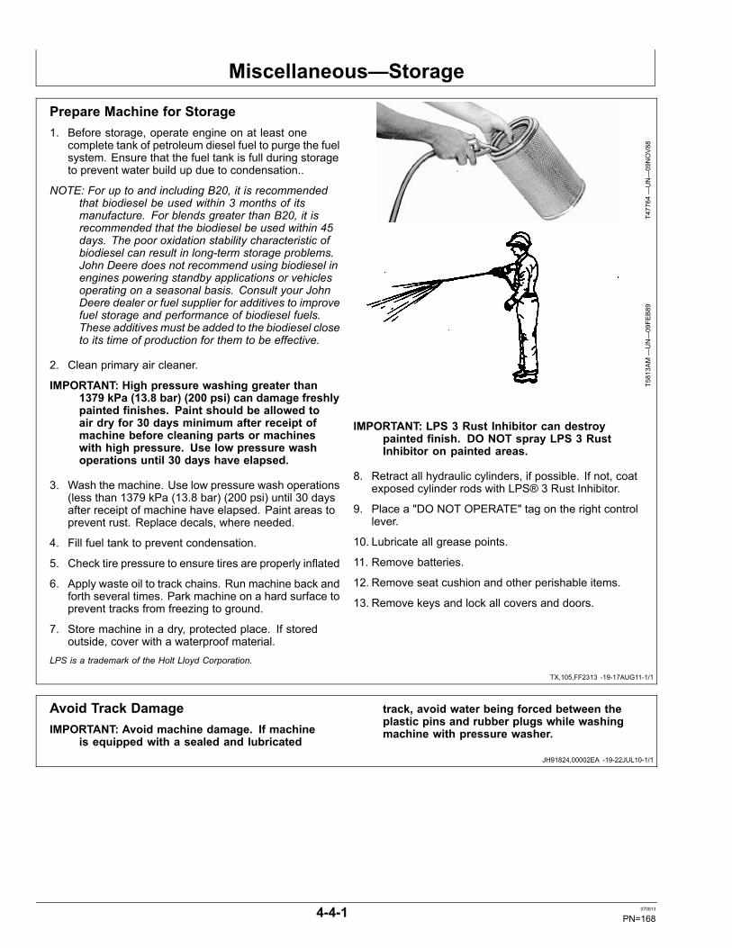
Miscellaneous—Storage
TX,105,FF2313 -19-17AUG11-1/1
JH91824,00002EA -19-22JUL10-1/1
Prepare Machine for Storage1. Before storage, operate engine on at least one
complete tank of petroleum diesel fuel to purge the fuelsystem. Ensure that the fuel tank is full during storageto prevent water build up due to condensation..
NOTE: For up to and including B20, it is recommendedthat biodiesel be used within 3 months of itsmanufacture. For blends greater than B20, it isrecommended that the biodiesel be used within 45days. The poor oxidation stability characteristic ofbiodiesel can result in long-term storage problems.John Deere does not recommend using biodiesel inengines powering standby applications or vehiclesoperating on a seasonal basis. Consult your JohnDeere dealer or fuel supplier for additives to improvefuel storage and performance of biodiesel fuels.These additives must be added to the biodiesel closeto its time of production for them to be effective.
2. Clean primary air cleaner.
IMPORTANT: High pressure washing greater than1379 kPa (13.8 bar) (200 psi) can damage freshlypainted finishes. Paint should be allowed toair dry for 30 days minimum after receipt ofmachine before cleaning parts or machineswith high pressure. Use low pressure washoperations until 30 days have elapsed.
3. Wash the machine. Use low pressure wash operations(less than 1379 kPa (13.8 bar) (200 psi) until 30 daysafter receipt of machine have elapsed. Paint areas toprevent rust. Replace decals, where needed.
4. Fill fuel tank to prevent condensation.
5. Check tire pressure to ensure tires are properly inflated
6. Apply waste oil to track chains. Run machine back andforth several times. Park machine on a hard surface toprevent tracks from freezing to ground.
7. Store machine in a dry, protected place. If storedoutside, cover with a waterproof material.
T47764
—UN—09NOV88
T5813A
M—UN—09FE
B89
IMPORTANT: LPS 3 Rust Inhibitor can destroypainted finish. DO NOT spray LPS 3 RustInhibitor on painted areas.
8. Retract all hydraulic cylinders, if possible. If not, coatexposed cylinder rods with LPS® 3 Rust Inhibitor.
9. Place a "DO NOT OPERATE" tag on the right controllever.
10. Lubricate all grease points.
11. Remove batteries.
12. Remove seat cushion and other perishable items.
13. Remove keys and lock all covers and doors.
LPS is a trademark of the Holt Lloyd Corporation.
Avoid Track DamageIMPORTANT: Avoid machine damage. If machine
is equipped with a sealed and lubricated
track, avoid water being forced between theplastic pins and rubber plugs while washingmachine with pressure washer.
4-4-1 070813
PN=168
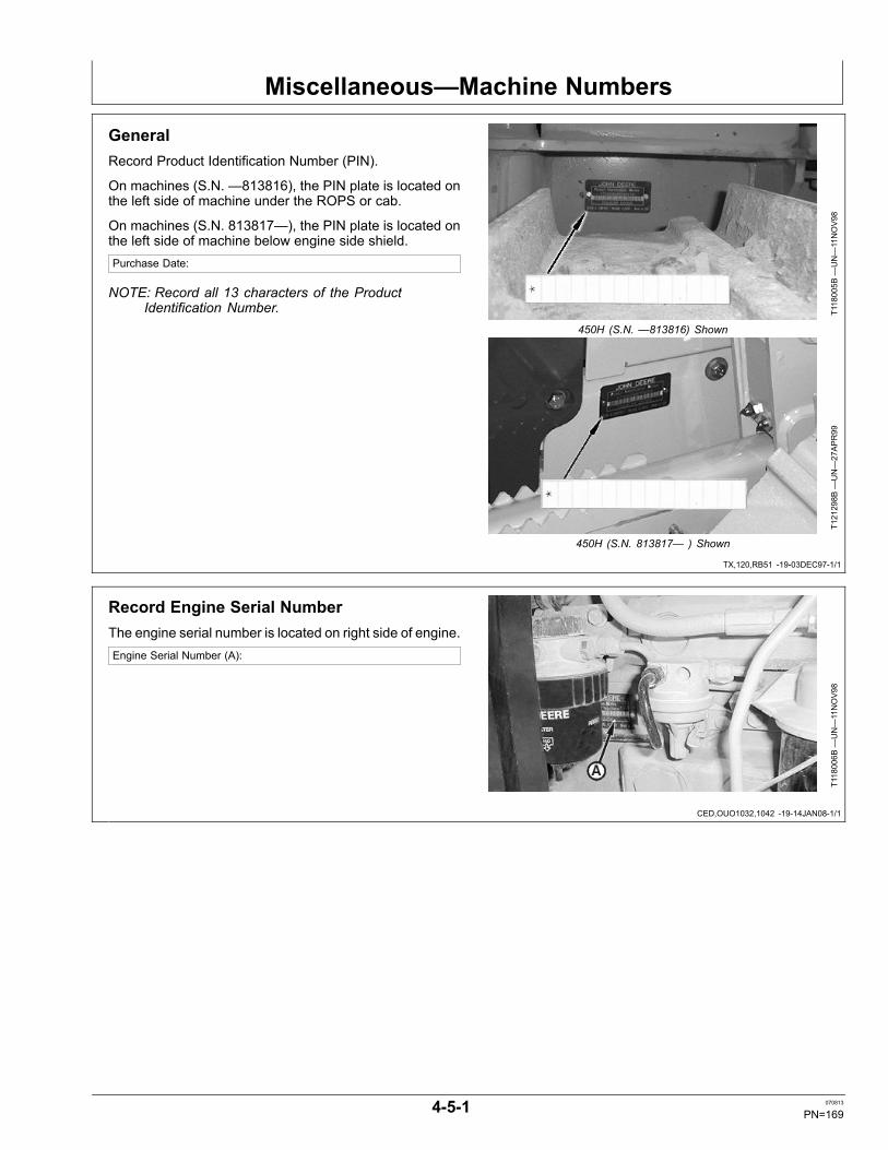
Miscellaneous—Machine Numbers
TX,120,RB51 -19-03DEC97-1/1
CED,OUO1032,1042 -19-14JAN08-1/1
GeneralRecord Product Identification Number (PIN).
On machines (S.N. —813816), the PIN plate is located onthe left side of machine under the ROPS or cab.
On machines (S.N. 813817—), the PIN plate is located onthe left side of machine below engine side shield.Purchase Date:
NOTE: Record all 13 characters of the ProductIdentification Number. T1
18005B
—UN—11NOV98
450H (S.N. —813816) Shown
T121298B
—UN—27APR99
450H (S.N. 813817— ) Shown
Record Engine Serial NumberThe engine serial number is located on right side of engine.Engine Serial Number (A):
T118006B
—UN—11NOV98
4-5-1 070813
PN=169

Miscellaneous—Machine Numbers
DX,SECURE2 -19-18NOV03-1/1
DX,SECURE1 -19-18NOV03-1/1
Keep Machines Secure1. Install vandal-proof devices.2. When machine is in storage:
- Lower equipment to the ground- Set wheels to widest position to make loading moredifficult
- Remove any keys and batteries3. When parking indoors, put large equipment in front of
exits and lock your storage buildings.4. When parking outdoors, store in a well-lighted and
fenced area.5. Make note of suspicious activity and report any thefts
immediately to law enforcement agencies.6. Notify your John Deere dealer of any losses.
TS230—UN—24MAY
89
Keep Proof of Ownership1. Maintain in a secure location an up-to-date inventory
of all product and component serial numbers.2. Regularly verify that identification plates have not
been removed. Report any evidence of tampering tolaw enforcement agencies and order duplicate plates.
3. Other steps you can take:- Mark your machine with your own numbering system- Take color photographs from several angles of eachmachine
TS1680
—UN—09DEC03
4-5-2 070813
PN=170

Miscellaneous—Specifications
Continued on next page CED,OUO1032,1142 -19-23MAR99-1/2
450H Crawler Dozer Dimensions
T118300—UN—11NOV98
NOTE: Specifications and design subject to changewithout notice. Whenever applicable, specificationsare in accordance with ICED and SAE standards.Except where otherwise noted, these specifications
are based on a unit with roll-over protectivestructure, full fuel tank, 80 kg (175 lb) operator,and standard equipment.
Item Measurement Specification
A—Overall Height—ROPS or Cab Height 2590 mm (8 ft 6 in.)
B—Blade Height 826 mm (2 ft 8.6 in.)
C—Blade Lift Height 773 mm (2 ft 6 in.)
D—Digging Depth 528 mm (1 ft 9 in.)E—Blade Tilt
90 inch (Narrow) Blade (Right Side) Distance 313 mm (1 ft)
97 inch (Standard) Blade (RightSide)
Distance 337 mm (1 ft 1.3 in.)
F—Blade Tilt
90 inch (Narrow) Blade (Left Side) Distance 313 mm (1 ft)
97 inch (Standard) Blade (LeftSide)
Distance 337 mm (1 ft 1.3 in.)
G—Overall (Without Winch) Length 3937 mm (12 ft 11 in.)
G—Overall (With Winch) Length 4496 mm (14 ft 9 in.)
H—Blade Width (90 inch Blade) Width 2286 mm (7 ft 6 in.)
H—Blade Width (97 inch Blade) Width 2464 mm (8 ft 1 in.)
4-6-1 070813
PN=171

Miscellaneous—Specifications
CED,OUO1032,1142 -19-23MAR99-2/2
CED,OUO1032,1143 -19-23MAR99-1/1
Item Measurement Specification
I—Blade Angle (90 inch Blade) Width 2064 mm (6 ft 9 in.)
I—Blade Angle (97 inch Blade) Width 2267 mm (7 ft 5.3 in.)
90 inch (Narrow) Blade Capacity 1.4 m3 (1.9 yd3)
97 inch (Standard) Blade Capacity 1.5 m3 (2.0 yd3)
450H Crawler Dozer SpecificationsItem Measurement Specification
John Deere PowerTech® 4045D4-Cylinder Diesel Engine
Engine Type Naturally Aspirated
Fuel Consumption, Typical Consumption 4.9—8.7 L/h (1.5—2.3 gph)
Rated Power at 2200 rpm Power 52 kW (70 hp) SAE net horsepower
Piston Displacement 4.52 L (276 cu in.)
Maximum Net Torque at 1200 rpm Torque Rise 305 N·m (225 lb-ft)
Batteries Voltage 12-volt
Alternator—ROPS Amperage 65 amp
Alternator—Cab with AirConditioning
Amperage 95 amp
Transmission Speed 0—8 km/h (0—5 mph)
Hydraulic System Pressure 20 685 kPa (3000 psi)Flow Rate 56.8 L/min (15 gpm) @ 2200 rpm
Undercarriage
Track Shoes (Each Side) Quantity 37
Ground Contact Area (with 16 in.Shoes)
Area 15 897 cm2 (2464 sq in.)
Track Pitch 160 mm (6.29 in.)Gauge 1450 mm (57 in.)
Minimum Ground (with Single BarGrouser)
Clearance 345 mm (13.6 in.)
Minimum Ground (with SwampShoes)
Clearance 366 mm (14.4 in.)
Ground Pressure Pressure 42 kPa (0.42 bar) (6.1 psi)PowerTech is a registered trademark of Deere & Company
4-6-2 070813
PN=172

Miscellaneous—Specifications
CED,OUO1032,1145 -19-23MAR99-1/1
450H Crawler Dozer WeightsItem Measurement Specification
SAE Operating Weight Weight 6804 kg (15,000 lb)Optional Equipment
Rock Guards (4) Weight 117 kg (257 lb)
Deluxe Seat (add) Weight 9 kg (20 lb)
Cab with Heater (add) Weight 268 kg (590 lb)
Cab with Air Conditioning (add) Weight 306 kg (675 lb)
ROPS Heater Weight 12 kg (26 lb)
High Intensity Lights Weight 4 kg (9 lb)
Front Tow Hook Weight 15 kg (33 lb)
Rigid Draw Bar Weight 23 kg (50 lb)
Extended Draw Bar Weight 33 kg (72 lb)
4000S Winch Weight 653 kg (1437 lb)
Winch Fairlead, Four Roller Weight 85 kg (187 lb)
Radial Ripper Weight 335 kg (738 lb)
Parallelogram Ripper Weight 592 kg (1306 lb)
4-6-3 070813
PN=173

Miscellaneous—Specifications
Continued on next page CED,OUO1032,1353 -19-23MAR99-1/2
450H-LT Crawler Dozer Dimensions
T118300—UN—11NOV98
NOTE: Specifications and design subject to changewithout notice. Whenever applicable, specificationsare in accordance with ICED and SAE standards.Except where otherwise noted, these specifications
are based on a unit with roll-over protectivestructure, full fuel tank, 80 kg (175 lb) operator,and standard equipment.
Item Measurement Specification
A—Overall Height—ROPS or Cab Height 2590 mm (8 ft 6 in.)
B—Blade Height 826 mm (2 ft 8.6 in.)
C—Blade Lift Height 773 mm (2 ft 6 in.)
D—Digging Depth 528 mm (1 ft 9 in.)E—Blade Tilt
90 inch (Narrow) Blade (Right Side) Distance 313 mm (1 ft)
97 inch (Standard) Blade (RightSide)
Distance 337 mm (1 ft 1.3 in.)
115 inch Blade (Right Side) Distance 400 mm (1 ft 3.8 in.)F—Blade Tilt
90 inch (Narrow) Blade (Left Side) Distance 313 mm (1 ft)
97 inch (Standard) Blade (LeftSide)
Distance 337 mm (1 ft 1.3 in.)
115 inch Blade (Left Side) Distance 400 mm (1 ft 3.8 in.)
G—Overall (Without Winch) Length 4013 mm (13 ft 2 in.)
G—Overall (With Winch) Length 4496 mm (14 ft 9 in.)
4-6-4 070813
PN=174

Miscellaneous—Specifications
CED,OUO1032,1353 -19-23MAR99-2/2
CED,OUO1032,1354 -19-23MAR99-1/1
Item Measurement Specification
H—Blade Width (90 inch Blade) Width 2286 mm (7 ft 6 in.)
H—Blade Width (97 inch Blade) Width 2464 mm (8 ft 1 in.)
H—Blade Width (115 inch Blade) Width 2921 mm (9 ft 7 in.)
I—Blade Angle (90 inch Blade) Width 2106 mm (6 ft 10.9 in.)
I—Blade Angle (97 inch Blade) Width 2267 mm (7 ft 5.3 in.)
I—Blade Angle (115 inch Blade) Width 2680 mm (8 ft 9.5 in.)
90 inch (Narrow) Blade Capacity 1.4 m3 (1.9 yd3)
97 inch (Standard) Blade Capacity 1.5 m3 (2.0 yd3)
115 inch Blade Capacity 1.75 m3 (2.3 yd3)
450H-LT Crawler Dozer SpecificationsItem Measurement Specification
John Deere PowerTech® 4045D4-Cylinder Diesel Engine
Engine Type Naturally Aspirated
Fuel Consumption, Typical Consumption 4.9—8.7 L/h (1.5—2.3 gph)
Rated Power at 2200 rpm Power 52 kW (70 hp) SAE net horsepower
Piston Displacement 4.52 L (276 cu in.)
Maximum Net Torque at 1300 rpm Torque Rise 313 N·m (230 lb-ft)
Batteries Voltage 12-volt
Alternator—ROPS Amperage 65 amp
Alternator—Cab with AirConditioning
Amperage 95 amp
Transmission Speed 0—8 km/h (0—5 mph)
Hydraulic System Pressure 20 685 kPa (3000 psi)Flow Rate 56.8 L/min (15 gpm) @ 2200 rpm
Undercarriage
Track Shoes (Each Side) Quantity 40
Ground Contact Area (with 16 in.Shoes)
Area 17 755 cm2 (2752 sq in.)
Track Pitch 160 mm (6.29 in.)Gauge 1450 mm (57 in.)
Minimum Ground (with Single BarGrouser)
Clearance 345 mm (13.6 in.)
Minimum Ground (with SwampShoes)
Clearance 366 mm (14.4 in.)
Ground Pressure Pressure 38.6 kPa (0.39 bar) (5.6 psi)PowerTech is a registered trademark of Deere & Company
4-6-5 070813
PN=175

Miscellaneous—Specifications
CED,OUO1032,1357 -19-23MAR99-1/1
450H-LT Crawler Dozer WeightsItem Measurement Specification
SAE Operating Weight Weight 6804 kg (15,000 lb)Optional Equipment
Rock Guards (4) Weight 131 kg (288 lb)
Deluxe Seat (add) Weight 9 kg (20 lb)
Cab with Heater (add) Weight 268 kg (590 lb)
Cab with Air Conditioning (add) Weight 306 kg (675 lb)
ROPS Heater Weight 12 kg (26 lb)
High Intensity Lights Weight 4 kg (9 lb)
Front Tow Hook Weight 15 kg (33 lb)
Rigid Draw Bar Weight 23 kg (50 lb)
Extended Draw Bar Weight 33 kg (72 lb)
4000S Winch Weight 653 kg (1437 lb)
Winch Fairlead, Four Roller Weight 85 kg (187 lb)
Radial Ripper Weight 335 kg (738 lb)
Parallelogram Ripper Weight 592 kg (1306 lb)
4-6-6 070813
PN=176

Miscellaneous—Specifications
Continued on next page CED,OUO1032,1163 -19-12NOV98-1/2
450H-LGP Crawler Dozer Dimensions
T118300—UN—11NOV98
NOTE: Specifications and design subject to changewithout notice. Whenever applicable, specificationsare in accordance with ICED and SAE standards.Except where otherwise noted, these specifications
are based on a unit with roll-over protectivestructure, full fuel tank, 80 kg (175 lb) operator,and standard equipment.
Item Measurement Specification
A—Overall Height—ROPS or Cab Height 2590 mm (8 ft 6 in.)
B—115 inch Blade Height 826 mm (2 ft 8.6 in.)
B—124 inch Blade Height 767 mm (2 ft 6.2 in.)
C—Blade Lift Height 773 mm (2 ft 6 in.)
D—Digging Depth 528 mm (1 ft 9 in.)E—Blade Tilt
115 inch Blade (Right Side) Distance 400 mm (1 ft 3 in.)
124 inch Blade (Right Side) Distance 432 mm (1 ft 5 in.)F—Blade Tilt
115 inch Blade (Left Side) Distance 400 mm (1 ft 3 in.)
124 inch Blade (Left Side) Distance 432 mm (1 ft 5 in.)
G—Overall (Without Winch) Length 4013 mm (13 ft 2 in.)
G—Overall (With Winch) Length 4496 mm (14 ft 9 in.)
H—Blade Width (115 inch Blade) Width 2921 mm (9 ft 7 in.)
H—Blade Width (124 inch Blade) Width 3150 mm (10 ft 4 in.)
4-6-7 070813
PN=177

Miscellaneous—Specifications
CED,OUO1032,1163 -19-12NOV98-2/2
CED,OUO1032,1355 -19-23MAR99-1/1
Item Measurement Specification
I—Blade Angle (115 inch Blade) Width 2639 mm (8 ft 8 in.)
I—Blade Angle (124 inch Blade) Width 2845 mm (9 ft 3 in.)
115 inch Blade Capacity 1.75 m3 (2.9 yd3)
124 inch Blade Capacity 1.64 m3 (2.15 yd3)
450H-LGP Crawler Dozer SpecificationsItem Measurement Specification
John Deere PowerTech® 4045T4-Cylinder Diesel Engine
Engine Type Turbocharged
Fuel Consumption, Typical Consumption 4.9—8.7 L/h (1.5—2.3 gph)
Rated Power at 2200 rpm Power 55 kW (74 hp) SAE net horsepower
Piston Displacement 4.52 L (276 cu in.)
Maximum Net Torque at 1300 rpm Torque Rise 340 N·m (250 lb-ft)
Batteries Voltage 12-volt
Alternator—ROPS Amperage 65 amp
Alternator—Cab with AirConditioning
Amperage 95 amp
Transmission Speed 0—8 km/h (0—5 mph)
Hydraulic System Pressure 20 685 kPa (3000 psi)Flow Rate 56.8 L/min (15 gpm) @ 2200 rpm
Undercarriage
Track Shoes (Each Side) Quantity 40
Ground Contact Area (with 24 in.Shoes)
Area 26 632 cm2 (4128 sq in.)
Track Pitch 160 mm (6.29 in.)Gauge 1650 mm (65 in.)
Minimum Ground (with Single BarGrouser)
Clearance 345 mm (13.6 in.)
Minimum Ground (with SwampShoes)
Clearance 366 mm (14.4 in.)
Ground Pressure Pressure 27.6 kPa (0.28 bar) (4.0 psi)PowerTech is a registered trademark of Deere & Company
4-6-8 070813
PN=178

Miscellaneous—Specifications
CED,OUO1032,1356 -19-23MAR99-1/1
CED,TX03768,2504 -19-06JUN05-1/1
450H-LGP Crawler Dozer WeightsItem Measurement Specification
SAE Operating Weight Weight 7484 kg (16,500 lb)Optional Equipment
Rock Guards (4) Weight 131 kg (288 lb)
Swamp Shoe Weight 11 kg (25 lb)
Deluxe Seat (add) Weight 9 kg (20 lb)
Cab with Heater (add) Weight 268 kg (590 lb)
Cab with Air Conditioning (add) Weight 306 kg (675 lb)
ROPS Heater Weight 12 kg (26 lb)
High Intensity Lights Weight 4 kg (9 lb)
Front Tow Hook Weight 15 kg (33 lb)
Rigid Draw Bar Weight 23 kg (50 lb)
Extended Draw Bar Weight 33 kg (72 lb)
4000S Winch Weight 653 kg (1437 lb)
Winch Fairlead, Four Roller Weight 85 kg (187 lb)
Radial Ripper Weight 335 kg (738 lb)
Parallelogram Ripper Weight 592 kg (1306 lb)
450H, 450H-LT and 450H-LGP Crawler DozerDrain and Refill CapacitiesItem Measurement Specification
Drain and Refill Capacities
Cooling System Capacity 14 L (15 qt)
Fuel Tank Capacity 136 L (36 gal)
Engine Oil (Including Filter) Capacity 14 L (15 qt)
Final Drive (Each Side) Capacity 8.5 L (9 qt)
Hydraulic Reservoir (IncludingFilter)
Capacity 32 L (8.5 gal)
Transmission Reservoir (IncludingFilter)
Capacity 53 L (14 gal)
Winch-If Equipped Capacity 37 L (10 gal)
4-6-9 070813
PN=179

Miscellaneous—Specifications
Continued on next page CED,OUO1032,1376 -19-07APR99-1/2
550H Crawler Dozer Dimensions
T118300—UN—11NOV98
NOTE: Specifications and design subject to changewithout notice. Whenever applicable, specificationsare in accordance with ICED and SAE standards.Except where otherwise noted, these specifications
are based on a unit with roll-over protectivestructure, full fuel tank, 80 kg (175 lb) operator,and standard equipment.
Item Measurement Specification
A—Overall Height—ROPS or Cab Height 2743 mm (9 ft)
B—Blade Height 826 mm (2 ft 8.6 in.)
C—Blade Lift Height 797 mm (2 ft 7.4 in.)
D—Digging Depth 523 mm (1 ft 8.6 in.)E—Blade Tilt
105 inch (Standard) Blade (RightSide)
Distance 364 mm (1 ft 2.3 in.)
97 inch (Narrow) Blade (Right Side) Distance 337 mm (1 ft 1.3 in.)F—Blade Tilt
105 inch (Standard) Blade (LeftSide)
Distance 313 mm (1 ft)
97 inch (Narrow) Blade (Left Side) Distance 337 mm (1 ft 1.3 in.)
G—Overall (Without Winch) Length 4040 mm (13 ft 3 in.)
G—Overall (With Winch) Length 4549 mm (14 ft 11 in.)
H—Blade Width (105 inchStandard Blade)
Width 2667 mm (8 ft 9 in.)
4-6-10 070813
PN=180

Miscellaneous—Specifications
CED,OUO1032,1376 -19-07APR99-2/2
CED,OUO1032,1378 -19-07APR99-1/1
Item Measurement Specification
H—Blade Width (97 inchNarrow Blade)
Width 2464 mm (8 ft 1 in.)
I—Blade Angle (105 inchStandard Blade)
Width 2507 mm (8 ft 2.7 in.)
I—Blade Angle (97 inch NarrowBlade)
Width 2318 mm (7 ft 7.2 in.)
105 inch (Standard) Blade Capacity 1.61 m3 (2.11 yd3)
97 inch (Narrow) Blade Capacity 1.5 m3 (2.0 yd3)
550H Crawler Dozer SpecificationsItem Measurement Specification
John Deere PowerTech® 4045T4-Cylinder Diesel Engine
Engine Type Turbocharged
Fuel Consumption, Typical Consumption 6.4—9.8 L/h (1.7—2.6 gph)
Rated Power at 2200 rpm Power 60 kW (80 hp) SAE net horsepower
Piston Displacement 4.52 L (276 cu in.)
Maximum Net Torque at 1200 rpm Torque Rise 344 N·m (255 lb-ft)
Batteries Voltage 12-volt
Alternator—ROPS Amperage 65 amp
Alternator—Cab with AirConditioning
Amperage 95 amp
Transmission Speed 0—8 km/h (0—5 mph)
Hydraulic System Pressure 20 685 kPa (3000 psi)Flow Rate 56.8 L/min (15 gpm) @ 2200 rpm
Undercarriage
Track Shoes (Each Side) Quantity 40
Ground Contact Area (with 18 in.Shoes)
Area 19 974 cm2 (3096 sq in.)
Track Pitch 160 mm (6.29 in.)Gauge 1550 mm (61 in.)
Minimum Ground (with Single BarGrouser)
Clearance 345 mm (13.6 in.)
Minimum Ground (with SwampShoes)
Clearance 366 mm (14.4 in.)
Ground Pressure Pressure 37.2 kPa (0.37 bar) (5.4 psi)
Standard Grouser Width 457 mm (18 in.)PowerTech is a registered trademark of Deere & Company
4-6-11 070813
PN=181

Miscellaneous—Specifications
CED,OUO1032,1380 -19-25MAR99-1/1
550H Crawler Dozer WeightsItem Measurement Specification
SAE Operating Weight Weight 7620 kg (16,800 lb)Optional Equipment
Rock Guards (4) Weight 131 kg (288 lb)
Deluxe Seat (add) Weight 9 kg (20 lb)
Cab with Heater (add) Weight 268 kg (590 lb)
Cab with Air Conditioning (add) Weight 306 kg (675 lb)
ROPS Heater Weight 12 kg (26 lb)
High Intensity Lights Weight 4 kg (9 lb)
Retrieval Hitch Weight 23 kg (50 lb)
Extended Draw Bar Weight 33 kg (72 lb)
4000S Winch Weight 653 kg (1437 lb)
Winch Fairlead, Four Roller Weight 85 kg (187 lb)
Radial Ripper Weight 335 kg (738 lb)
Parallelogram Ripper Weight 592 kg (1306 lb)
4-6-12 070813
PN=182

Miscellaneous—Specifications
Continued on next page CED,OUO1032,1377 -19-25MAR99-1/2
550H-LGP Crawler Dozer Dimensions
T118300—UN—11NOV98
NOTE: Specifications and design subject to changewithout notice. Whenever applicable, specificationsare in accordance with ICED and SAE standards.Except where otherwise noted, these specifications
are based on a unit with roll-over protectivestructure, full fuel tank, 80 kg (175 lb) operator,and standard equipment.
Item Measurement Specification
A—Overall Height—ROPS or Cab Height 2743 mm (9 ft)
B—115 inch Blade Height 826 mm (2 ft 8.6 in.)
B—128 inch Blade Height 767 mm (2 ft 6.2 in.)
C—Blade Lift Height 797 mm (2 ft 7.4 in.)
D—Digging Depth 523 mm (1 ft 8.6 in.)E—Blade Tilt
115 inch Blade (Right Side) Distance 399 mm (1 ft 3 in.)
128 inch Blade (Right Side) Distance 444 mm (1 ft 5.5 in.)F—Blade Tilt
115 inch Blade (Left Side) Distance 399 mm (1 ft 3 in.)
128 inch Blade (Left Side) Distance 444 mm (1 ft 5.5 in.)
G—Overall (Without Winch) Length 4040 mm (13 ft 3 in.)
G—Overall (With Winch) Length 4549 mm (14 ft 11 in.)
H—Blade Width (115 inch Blade) Width 2921 mm (9 ft 7 in.)
H—Blade Width (128 inch Blade) Width 3251 mm (10 ft 8 in.)
4-6-13 070813
PN=183

Miscellaneous—Specifications
CED,OUO1032,1377 -19-25MAR99-2/2
CED,OUO1032,1379 -19-25MAR99-1/1
Item Measurement Specification
I—Blade Angle (115 inch Blade) Width 2742 mm (8 ft 11.9 in.)
I—Blade Angle (128 inch Blade) Width 3070 mm (10 ft 0.9 in.)
115 inch Blade Capacity 1.75 m3 (2.9 yd3)
128 inch Blade Capacity 1.69 m3 (2.21 yd3)
550H-LGP Crawler Dozer SpecificationsItem Measurement Specification
John Deere PowerTech® 4045T4-Cylinder Diesel Engine
Engine Type Turbocharged
Fuel Consumption, Typical Consumption 6.4—9.8 L/h (1.7—2.6 gph)
Rated Power at 2200 rpm Power 63 kW (84 hp) SAE net horsepower
Piston Displacement 4.52 L (276 cu in.)
Maximum Net Torque at 1200 rpm Torque Rise 372 N·m (276 lb-ft)
Batteries Voltage 12-volt
Alternator—ROPS Amperage 65 amp
Alternator—Cab with AirConditioning
Amperage 95 amp
Transmission Speed 0—8 km/h (0—5 mph)
Hydraulic System Pressure 20 685 kPa (3000 psi)Flow Rate 56.8 L/min (15 gpm) @ 2200 rpm
Undercarriage
Track Shoes (Each Side) Quantity 40
Ground Contact Area (with 24 in.Shoes)
Area 26 632 cm2 (4128 sq in.)
Track Pitch 160 mm (6.29 in.)Gauge 1753 mm (69 in.)
Minimum Ground (with Single BarGrouser)
Clearance 345 mm (13.6 in.)
Minimum Ground (with SwampShoes)
Clearance 366 mm (14.4 in.)
Ground Pressure Pressure 29 kPa (0.29 bar) (4.2 psi)PowerTech is a registered trademark of Deere & Company
4-6-14 070813
PN=184

Miscellaneous—Specifications
CED,OUO1032,1381 -19-25MAR99-1/1
CED,OUO1032,1382 -19-06JUN05-1/1
550H-LGP Crawler Dozer WeightsItem Measurement Specification
SAE Operating Weight Weight 7938 kg (17,500 lb)Optional Equipment
Rock Guards (4) Weight 131 kg (288 lb)
Swamp Shoe Weight 73 kg (160 lb)
Deluxe Seat (add) Weight 9 kg (20 lb)
Cab with Heater (add) Weight 268 kg (590 lb)
Cab with Air Conditioning (add) Weight 306 kg (675 lb)
ROPS Heater Weight 12 kg (26 lb)
High Intensity Lights Weight 4 kg (9 lb)
Front Tow Hook Weight 15 kg (33 lb)
Retrieval Hitch Weight 23 kg (50 lb)
Extended Draw Bar Weight 33 kg (72 lb)
4000S Winch Weight 653 kg (1437 lb)
Winch Fairlead, Four Roller Weight 85 kg (187 lb)
Radial Ripper Weight 335 kg (738 lb)
Parallelogram Ripper Weight 592 kg (1306 lb)
550H and 550H-LGP Crawler Dozer Drain andRefill CapacitiesItem Measurement Specification
Drain and Refill Capacities
Cooling System Capacity 14 L (15 qt)
Fuel Tank Capacity 178 L (47 gal)
Engine Oil (Including Filter) Capacity 14L (15 qt)
Final Drive (Each Side) Capacity 8.5 L (9 qt)
Hydraulic Reservoir (IncludingFilter)
Capacity 32 L (8.5 gal)
Transmission Reservoir (IncludingFilter)
Capacity 53 L (14 gal)
Winch-If Equipped Capacity 37 L (10 gal)
4-6-15 070813
PN=185

Miscellaneous—Specifications
Continued on next page CED,OUO1032,1376 -19-18JUN02-1/2
650H Crawler Dozer Dimensions
T118300—UN—11NOV98
NOTE: Specifications and design subject to changewithout notice. Whenever applicable, specificationsare in accordance with ICED and SAE standards.Except where otherwise noted, these specifications
are based on a unit with roll-over protectivestructure, full fuel tank, 80 kg (175 lb) operator,and standard equipment.
Item Measurement Specification
A—Overall Height—ROPS or Cab Height 2768 mm (9 ft 1 in.)
B—105 inch (Standard) Blade Height 933 mm (3 ft 0.7 in.)
B—97 inch (Narrow) Blade Height 826 mm (2 ft 8.6 in.)
C—Blade Lift Height 819 mm (2 ft 8.2 in.)
D—Digging Depth 500 mm (1 ft 7.7 in.)E—Blade Tilt
105 inch (Standard) Blade (RightSide)
Distance 364 mm (1 ft 2.3 in.)
97 inch (Narrow) Blade (Right Side) Distance 337 mm (1 ft 1.3 in.)F—Blade Tilt
105 inch (Standard) Blade (LeftSide)
Distance 364 mm (1 ft 2.3 in.)
97 inch (Narrow) Blade (Left Side) Distance 337 mm (1 ft 1.3 in.)
G—Overall (Without Winch) Length 4070 mm (13 ft 4 in.)
G—Overall (With Winch) Length 4547 mm (14 ft 11 in.)
H—Blade Width (105 inchStandard Blade)
Width 2667 mm (8 ft 9 in.)
4-6-16 070813
PN=186

Miscellaneous—Specifications
CED,OUO1032,1376 -19-18JUN02-2/2
CED,OUO1032,1385 -19-18JUN02-1/1
Item Measurement Specification
H—Blade Width (97 inchNarrow Blade)
Width 2464 mm (8 ft 1 in.)
I—Blade Angle (105 inchStandard Blade)
Width 2507 mm (8 ft 2.7 in.)
I—Blade Angle (97 inch NarrowBlade)
Width 2318 mm (7 ft 7.2 in.)
105 inch (Standard) Blade Capacity 1.99 m3 (2.6 yd3)
97 inch (Narrow) Blade Capacity 1.5 m3 (2.0 yd3)
650H Crawler Dozer SpecificationsItem Measurement Specification
John Deere PowerTech® 4045T4-Cylinder Diesel Engine
Engine Type Turbocharged
Fuel Consumption, Typical Consumption 7.2—11.2 L/h (1.9—3.0 gph)
Rated Power at 2200 rpm Power 67 kW (90 hp) SAE net horsepower
Piston Displacement 4.52 L (276 cu in.)
Maximum Net Torque at 1200 rpm Torque Rise 405 N·m (316 lb-ft)
Batteries Voltage 12-volt
Alternator—ROPS Amperage 65 amp
Alternator—Cab with AirConditioning
Amperage 95 amp
Transmission Speed 0—8 km/h (0—5 mph)
Hydraulic System Pressure 20 685 kPa (3000 psi)Flow Rate 56.8 L/min (15 gpm) @ 2200 rpm
Undercarriage
Track Shoes (Each Side) Quantity 38
Ground Contact Area (with 18 in.Shoes)
Area 19 974 cm2 (3096 sq in.)
Track Pitch 171 mm (6.73 in.)Gauge 1550 mm (61 in.)
Minimum Ground (with Single BarGrouser)
Clearance 363 mm (14.3 in.)
Minimum Ground (with SwampShoes)
Clearance 384 mm (15.1 in.)
Ground Pressure Pressure 40.6 kPa (0.41 bar) (5.9 psi)
Standard Grouser Width 457 mm (18 in.)PowerTech is a registered trademark of Deere & Company
4-6-17 070813
PN=187

Miscellaneous—Specifications
CED,OUO1032,1387 -19-18JUN02-1/1
650H Crawler Dozer WeightsItem Measurement Specification
SAE Operating Weight Weight 8391 kg (18,500 lb)Optional Equipment
Rock Guards (4) Weight 118 kg (260 lb)
Deluxe Seat (add) Weight 9 kg (20 lb)
Cab with Heater (add) Weight 268 kg (590 lb)
Cab with Air Conditioning (add) Weight 306 kg (675 lb)
ROPS Heater Weight 12 kg (26 lb)
High Intensity Lights Weight 4 kg (9 lb)
Retrieval Hitch Weight 23 kg (50 lb)
Extended Draw Bar Weight 33 kg (72 lb)
4000S Winch Weight 653 kg (1437 lb)
Winch Fairlead, Four Roller Weight 85 kg (187 lb)
Radial Ripper Weight 335 kg (738 lb)
Parallelogram Ripper Weight 592 kg (1306 lb)
4-6-18 070813
PN=188

Miscellaneous—Specifications
Continued on next page CED,OUO1032,1384 -19-25MAR99-1/2
650H-LGP Crawler Dozer Dimensions
T118300—UN—11NOV98
NOTE: Specifications and design subject to changewithout notice. Whenever applicable, specificationsare in accordance with ICED and SAE standards.Except where otherwise noted, these specifications
are based on a unit with roll-over protectivestructure, full fuel tank, 80 kg (175 lb) operator,and standard equipment.
Item Measurement Specification
A—Overall Height—ROPS or Cab Height 2768 mm (9 ft 1 in.
B—Blade Height 826 mm (2 ft 8.6 in.)
C—Blade Lift Height 819 mm (2 ft 8.2 in.)
D—Digging Depth 500 mm (1 ft 7.7 in.)E—Blade Tilt
115 inch Blade (Right Side) Distance 399 mm (1 ft 3 in.)
128 inch Blade (Right Side) Distance 444 mm (1 ft 5.5 in.)F—Blade Tilt
115 inch Blade (Left Side) Distance 399 mm (1 ft 3 in.)
128 inch Blade (Left Side) Distance 444 mm (1 ft 5.5 in.)
G—Overall (Without Winch) Length 4070 mm (13 ft 4 in.)
G—Overall (With Winch) Length 4547 mm (14 ft 11 in.)
H—Blade Width (115 inch Blade) Width 2921 mm (9 ft 7 in.)
H—Blade Width (128 inch Blade) Width 3251 mm (10 ft 8 in.)
I—Blade Angle (115 inch Blade) Width 2742 mm (8 ft 11.9 in.)
4-6-19 070813
PN=189
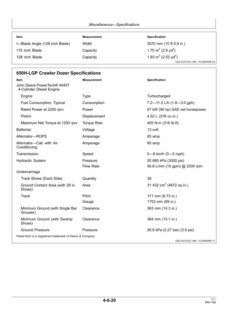
Miscellaneous—Specifications
CED,OUO1032,1384 -19-25MAR99-2/2
CED,OUO1032,1386 -19-25MAR99-1/1
Item Measurement Specification
I—Blade Angle (128 inch Blade) Width 3070 mm (10 ft 0.9 in.)
115 inch Blade Capacity 1.75 m3 (2.9 yd3)
128 inch Blade Capacity 1.93 m3 (2.52 yd3)
650H-LGP Crawler Dozer SpecificationsItem Measurement Specification
John Deere PowerTech® 4045T4-Cylinder Diesel Engine
Engine Type Turbocharged
Fuel Consumption, Typical Consumption 7.2—11.2 L/h (1.9—3.0 gph)
Rated Power at 2200 rpm Power 67 kW (90 hp) SAE net horsepower
Piston Displacement 4.52 L (276 cu in.)
Maximum Net Torque at 1200 rpm Torque Rise 405 N·m (316 lb-ft)
Batteries Voltage 12-volt
Alternator—ROPS Amperage 65 amp
Alternator—Cab with AirConditioning
Amperage 95 amp
Transmission Speed 0—8 km/h (0—5 mph)
Hydraulic System Pressure 20 685 kPa (3000 psi)Flow Rate 56.8 L/min (15 gpm) @ 2200 rpm
Undercarriage
Track Shoes (Each Side) Quantity 38
Ground Contact Area (with 28 in.Shoes)
Area 31 432 cm2 (4872 sq in.)
Track Pitch 171 mm (6.73 in.)Gauge 1753 mm (69 in.)
Minimum Ground (with Single BarGrouser)
Clearance 363 mm (14.3 in.)
Minimum Ground (with SwampShoes)
Clearance 384 mm (15.1 in.)
Ground Pressure Pressure 26.9 kPa (0.27 bar) (3.9 psi)PowerTech is a registered trademark of Deere & Company
4-6-20 070813
PN=190

Miscellaneous—Specifications
CED,OUO1032,1381 -19-25MAR99-1/1
650H-LGP Crawler Dozer WeightsItem Measurement Specification
SAE Operating Weight Weight 8664 kg (19,100 lb)Optional Equipment
Rock Guards (4) Weight 131 kg (288 lb)
Swamp Shoe Weight 72 kg (158 lb)
Deluxe Seat (add) Weight 9 kg (20 lb)
Cab with Heater (add) Weight 268 kg (590 lb)
Cab with Air Conditioning (add) Weight 306 kg (675 lb)
ROPS Heater Weight 12 kg (26 lb)
High Intensity Lights Weight 4 kg (9 lb)
Front Tow Hook Weight 15 kg (33 lb)
Retrieval Hitch Weight 23 kg (50 lb)
Extended Draw Bar Weight 33 kg (72 lb)
4000S Winch Weight 653 kg (1437 lb)
Winch Fairlead, Four Roller Weight 85 kg (187 lb)
Radial Ripper Weight 335 kg (738 lb)
Parallelogram Ripper Weight 592 kg (1306 lb)
4-6-21 070813
PN=191

Miscellaneous—Specifications
Continued on next page HG31779,0000094 -19-18JUN02-1/2
650H-XLT Crawler Dozer Dimensions
T118300—UN—11NOV98
NOTE: Specifications and design subject to changewithout notice. Whenever applicable, specificationsare in accordance with ICED and SAE standards.Except where otherwise noted, these specifications
are based on a unit with roll-over protectivestructure, full fuel tank, 80 kg (175 lb) operator,and standard equipment.
Item Measurement Specification
A—Overall Height—ROPS or Cab Height 2768 mm (9 ft 1 in.)
B—105 inch (Standard) Blade Height 933 mm (3 ft 0.7 in.)
B—97 inch (Narrow) Blade Height 826 mm (2 ft 8.6 in.)
C—Blade Lift Height 819 mm (2 ft 8.2 in.)
D—Digging Depth 500 mm (1 ft 7.7 in.)E—Blade Tilt
105 inch (Standard) Blade (RightSide)
Distance 364 mm (1 ft 2.3 in.)
97 inch (Narrow) Blade (Right Side) Distance 337 mm (1 ft 1.3 in.)F—Blade Tilt
105 inch (Standard) Blade (LeftSide)
Distance 364 mm (1 ft 2.3 in.)
97 inch (Narrow) Blade (Left Side) Distance 337 mm (1 ft 1.3 in.)
G—Overall (Without Winch) Length 4260 mm (13 ft 11 in.)
G—Overall (With Winch) Length 4737 mm (15 ft 7 in.)
H—Blade Width (105 inchStandard Blade)
Width 2667 mm (8 ft 9 in.)
4-6-22 070813
PN=192

Miscellaneous—Specifications
HG31779,0000094 -19-18JUN02-2/2
HG31779,0000095 -19-18JUN02-1/1
Item Measurement Specification
H—Blade Width (97 inchNarrow Blade)
Width 2464 mm (8 ft 1 in.)
I—Blade Angle (105 inchStandard Blade)
Width 2507 mm (8 ft 2.7 in.)
I—Blade Angle (97 inch NarrowBlade)
Width 2318 mm (7 ft 7.2 in.)
105 inch (Standard) Blade Capacity 1.99 m3 (2.6 yd3)
97 inch (Narrow) Blade Capacity 1.5 m3 (2.0 yd3)
650H-XLT Crawler Dozer SpecificationsItem Measurement Specification
John Deere PowerTech® 4045T4-Cylinder Diesel Engine
Engine Type Turbocharged
Fuel Consumption, Typical Consumption 7.2—11.2 L/h (1.9—3.0 gph)
Rated Power at 2200 rpm Power 67 kW (90 hp) SAE net horsepower
Piston Displacement 4.52 L (276 cu in.)
Maximum Net Torque at 1200 rpm Torque Rise 405 N·m (316 lb-ft)
Batteries Voltage 12-volt
Alternator—ROPS Amperage 65 amp
Alternator—Cab with AirConditioning
Amperage 95 amp
Transmission Speed 0—8 km/h (0—5 mph)
Hydraulic System Pressure 20 685 kPa (3000 psi)Flow Rate 56.8 L/min (15 gpm) @ 2200 rpm
Undercarriage
Track Shoes (Each Side) Quantity 40
Ground Contact Area (with 18 in.Shoes)
Area 21 368 cm2 (3312 sq in.)
Track Pitch 171 mm (6.73 in.)Gauge 1550 mm (61 in.)
Minimum Ground (with Single BarGrouser)
Clearance 363 mm (14.3 in.)
Minimum Ground (with SwampShoes)
Clearance 384 mm (15.1 in.)
Ground Pressure Pressure 38.5 kPa (0.38 bar) (5.6 psi)
Standard Grouser Width 457 mm (18 in.)PowerTech is a registered trademark of Deere & Company
4-6-23 070813
PN=193

Miscellaneous—Specifications
HG31779,0000096 -19-18JUN02-1/1
CED,OUO1032,1389 -19-06JUN05-1/1
TX,115,RR2763 -19-14JAN08-1/1
650H-XLT Crawler Dozer WeightsItem Measurement Specification
SAE Operating Weight Weight 8437 kg (18,600 lb)Optional Equipment
Rock Guards (4) Weight 134 kg (295 lb)
Deluxe Seat (add) Weight 9 kg (20 lb)
Cab with Heater (add) Weight 268 kg (590 lb)
Cab with Air Conditioning (add) Weight 306 kg (675 lb)
ROPS Heater Weight 12 kg (26 lb)
High Intensity Lights Weight 4 kg (9 lb)
Retrieval Hitch Weight 23 kg (50 lb)
Extended Draw Bar Weight 33 kg (72 lb)
4000S Winch Weight 653 kg (1437 lb)
Winch Fairlead, Four Roller Weight 85 kg (187 lb)
Radial Ripper Weight 335 kg (738 lb)
Parallelogram Ripper Weight 592 kg (1306 lb)
650H, 650H-LGP and 650H-XLT CrawlerDozer Drain and Refill CapacitiesItem Measurement Specification
Drain and Refill Capacities
Cooling System Capacity 14 L (15 qt)
Fuel Tank Capacity 178 L (47 gal)
Engine Oil (Including Filter) Capacity 14 L (15 qt)
Final Drive (Each Side) Capacity 8.5 L (9 qt)
Hydraulic Reservoir (IncludingFilter)
Capacity 32 L (8.5 gal)
Transmission Reservoir (IncludingFilter)
Capacity 53 L (14 gal)
Winch-If Equipped Capacity 37 L (10 gal)
4000S WinchMaximum Cable Capacities
Cable Size Winch Capacity15.88 mm (0.625 in.) 77.4 m (254 ft)19.05 mm (0.75 in.) 54.6 m (179 ft)22.23 mm (0.875 in.) 39.3 m (129 ft)
4-6-24 070813
PN=194

Index
Page
A
AdjustmentTrack sag ............................................................... 3-3-3Winch free spool drag.......................................... 2-2-35
Adjustment, armrest ................................................ 2-1-11Adjustment, engine speed....................................... 4-1-19Air cleanerChanging elements ................................................ 3-8-2
Air conditionerRefrigerant level, check ....................................... 4-1-17
Air conditioning.......................................................... 2-1-8Air intake hose........................................................... 3-7-1AlternatorPrecaution.............................................................. 4-1-4
AntifreezeChanging................................................................ 4-1-1Level ...................................................................... 3-4-1
Armrest .................................................................... 2-1-11Auxiliary power outlet ................................................ 2-1-9
B
BatteryElectrolyte level...................................................... 3-7-5Explosions, prevent................................................ 1-2-4Handling, checking, servicing ................................ 4-1-5Jump starting ....................................................... 2-2-17Remove.................................................................. 4-1-7Replace.................................................................. 4-1-6
Belt, serpentineInspect ................................................................... 3-3-1
BladeAngling................................................................. 2-2-30Operation ............................................................. 2-2-29Pitch operation..................................................... 2-2-28Tilt ........................................................................ 2-2-29
Bolt and screw torque valuesMetric ................................................................... 4-1-23Unified inch .......................................................... 4-1-22
Brake, parkReleasing............................................................. 2-2-37
Break-in engine oil..................................................... 3-1-3Break-In oil changeEngine.................................................................... 3-5-1
Breather filterWinch..................................................................... 3-8-5
C
Cab filter, air recirculation ........................................ 4-1-16Cab filter, fresh air ................................................... 4-1-16Cable specifications, winch ..................................... 4-6-24Cable, winch............................................................ 2-2-32Capacities450H, 450H-LT, 450H-LGP crawler dozerdrain and refill....................................................... 4-6-9
Page
550H, 550H-LGP crawler dozer drain and refill ... 4-6-15650H, 650H-LGP crawler dozer drain and refill ... 4-6-24
Chemical productsHandling................................................................. 1-2-4
Codes, service......................................................... 4-3-10Cold weatherMachine warming................................................. 2-2-18Starting................................................................... 2-2-8
ConsoleOptional gauges..................................................... 2-1-1
Control valve............................................................ 4-1-19CoolantChanging................................................................ 4-1-1Conditioner............................................................. 3-7-4Diesel engine ......................................................... 3-1-8Heater .................................................................... 2-2-9Level ...................................................................... 3-4-1
Cooling system checks.............................................. 4-2-1Cooling system fill...................................................... 4-1-2Coolscan Plus............................................................ 3-2-3Cylinder service ....................................................... 4-1-19
D
Daily machine check.................................................. 2-2-1Damper. replace........................................................ 4-1-2DeceleratorPedal.................................................................... 2-2-26
Diagnose malfunctionsTroubleshooting procedure .................................... 4-3-1
Diesel engine oil ........................................................ 3-1-4Diesel fuel.................................................................. 3-1-1Diesel fuel conditionerLow sulfur............................................................... 3-1-1
Diesel fuel, testingTesting Diesel Fuel................................................. 3-1-1
Diesel heater ........................................................... 2-2-10Dimensions450H crawler dozer................................................ 4-6-1450H-LGP crawler dozer ....................................... 4-6-7450H-LT crawler dozer........................................... 4-6-4550H crawler dozer.............................................. 4-6-10550H-LGP crawler dozer ..................................... 4-6-13650H crawler dozer..................................4-6-16, 4-6-22650H-LGP crawler dozer ..................................... 4-6-19
Display windowTransmission control unit ....................................... 2-1-5
Dozer linkage, lubricate ............................................. 3-4-4Driving the machine........................ 2-2-18, 2-2-21, 2-2-22Dust unloader valveClean...................................................................... 3-4-4Replace.................................................................. 3-8-3
Continued on next page
Index-1 070813
PN=1

Index
Page
E
ElectricalTroubleshooting ..................................................... 4-3-5
ElementPrimaryCleaning and inspecting ..................................... 4-1-4
EmergenciesPrepare for ............................................................. 1-2-5
EngineBoost starting....................................................... 2-2-17Break-In oil change................................................ 3-5-1Coolant heater ....................................................... 2-2-9Coolant level .......................................................... 3-4-1Crankcase vent tube.............................................. 3-8-1Fuel-fired coolant heater ...................................... 2-2-10Oil change....................................................3-6-1, 3-7-1Oil level .................................................................. 3-4-2Serial number record ............................................. 4-5-1Speed control lever .............................................. 2-2-25Starting.........................................................2-2-4, 2-2-6Troubleshooting ..................................................... 4-3-2Valve clearance, check and adjust......................... 3-9-1Warm-up .............................................................. 2-2-17
Engine air screen....................................................... 4-1-2Engine damper, replace............................................. 4-1-2Engine oilBreak-In ................................................................. 3-1-3Diesel ..................................................................... 3-1-4
Engine speed control leverAdjust tension ...................................................... 4-1-19
Engine, air filter replace............................................. 3-8-2Equipment, protectiveWear ...................................................................... 1-2-2
F
FilterAir recirculation .................................................... 4-1-16Air, cab................................................................. 4-1-16Engine..........................................................3-5-1, 3-7-1Final fuel, drain sediment....................................... 3-6-1Fuel ........................................................................ 3-7-2Fuel/water separator .............................................. 3-4-2
Filter, engine air, replace ........................................... 3-8-2Filter, hydraulic oil, change........................................ 3-9-1Filter, transmission oil, replace .................................. 3-9-2Filter, winch breather, replace.................................... 3-8-5Filter, winch oilReplace........................................................3-7-7, 3-8-4
Final driveOil change.............................................................. 3-8-1Oil level .................................................................. 3-6-1
Final drivesOilSpecifications ..................................................... 3-1-6
Fires, prevent............................................................. 1-2-4
Page
Fluids, high pressureAvoid ...................................................................... 1-2-3
FNRForward SpeedSwitch...................................................2-2-21, 2-2-22
Lever ........................................................2-2-21, 2-2-22Steer leverSpeed-In-Grip................................................... 2-2-24
FNR with speed in grip ................................2-2-20, 2-2-25Front idlerOil specification...................................................... 3-1-4
FuelDiesel ..................................................................... 3-1-1Filter change .......................................................... 3-7-2Filter replace .......................................................... 3-7-3Handling and storing.............................................. 3-1-2
Fuel filter, finalDrain sediment....................................................... 3-6-1
Fuel fired heater ...................................................... 2-2-10Fuel system checks................................................... 4-2-3Fuel tankCapacity ................................................................. 3-2-2Drain .................................................................... 4-1-15
Fuel/water separatorFilter drain sediment .............................................. 3-4-2
Fumes, exhaustBeware................................................................... 1-2-3
Fuse specificationsCab units..................................................4-1-12, 4-1-14ROPS units ................................................4-1-8, 4-1-10
G
GaugesTroubleshooting ..................................................... 4-3-9
Grease....................................................................... 3-1-7Alternative and synthetic lubricants ....................... 3-1-2
Grease dozer linkage ................................................ 3-4-4
H
HardwareTorque specifications ........................................... 4-1-21
Hardware torque valuesMetric ................................................................... 4-1-23Unified inch .......................................................... 4-1-22
HazardsAvoiding ................................................................. 1-3-1
Heater........................................................................ 2-1-8Heater, coolant ........................................................ 2-2-10Horn switch................................................................ 2-1-9HoseAir intake................................................................ 3-7-1
Hour meter................................................................. 3-2-1HydraulicOil and filter change............................................... 3-9-1Oil level .................................................................. 3-4-3
Continued on next page
Index-2 070813
PN=2

Index
Page
Troubleshooting ..................................................... 4-3-7Hydraulic breather filter, winchReplace.................................................................. 3-8-5
I
IdlerFront, oil specification ............................................ 3-1-4
IndicatorTroubleshooting ..................................................... 4-3-9
InjectionNozzle .................................................................... 4-1-3Pump...................................................................... 4-1-3
InstrumentCheck before starting............................................. 2-2-3Panel...................................................................... 2-2-2Panel, optional gauges .......................................... 2-1-1
L
LeverEngine speed control ........................................... 2-2-25FNR..........................................................2-2-21, 2-2-22Speed-In-Grip................................................... 2-2-24
Park brake............................................................ 2-2-26Steering................................................................ 2-2-23
LoadingMachine on a trailer ............................................. 2-2-36
Low sulfur diesel fuel conditioner .............................. 3-1-1LubricantsAlternative and synthetic lubricants ....................... 3-1-2SpecificationsOil, final drives.................................................... 3-1-6
LubricateFittings, dozer linkage............................................ 3-4-4
M
MachineCold weather warming ......................................... 2-2-18Maintenance preparation ....................................... 3-2-1
Machine towing........................................................ 2-2-37Machine, inspect........................................................ 1-2-2MaintenanceRecord keeping...................................................... 3-2-2
Maintenance repair record......................................... 3-2-4Metric bolt and screw torque values ........................ 4-1-23MonitorDisplay window ...................................................... 2-1-4Select button.......................................................... 2-1-4
N
Neutral start systemCheck................................................................... 4-1-20
Non-suspension seat............................................... 2-1-10
Page
O
OilAdding to roller..................................................... 4-1-19Alternative and synthetic lubricants ....................... 3-1-2Final drive oilSpecifications ..................................................... 3-1-6
Specification carrier roller ...................................... 3-1-4Specification front idler........................................... 3-1-4Specification track frame pivot ............................... 3-1-4Specification track roller......................................... 3-1-4Specification transmission ..................................... 3-1-5
Oil and filter changeHydraulic ................................................................ 3-9-1Transmission.......................................................... 3-9-2
Oil changeEngine..........................................................3-6-1, 3-7-1Final drive .............................................................. 3-8-1
Oil levelEngine.................................................................... 3-4-2Final drive .............................................................. 3-6-1Hydraulic ................................................................ 3-4-3Transmission.......................................................... 3-4-3
Oil, winchCheck..................................................................... 3-4-5Drain and refill........................................................ 3-8-4
Oilscan Plus............................................................... 3-2-3Operation qualification............................................... 1-2-1Operational checkAccessory ............................................................ 4-2-15Hydraulic system.................................................. 4-2-12Undercarriage ...................................................... 4-2-14
Operational checkout................................................. 4-2-1Indicators, shift linkage, alarm ............................. 4-2-11Neutral start switch and circuit ............................. 4-2-11
OutletAuxiliary power....................................................... 2-1-9
P
Park brakeOperation ............................................................. 2-2-26
Park brake, releasing............................................... 2-2-37Parking machine...................................................... 2-2-27Parts, movingStay clear ............................................................... 1-2-2
PedalBrake.................................................................... 2-2-26Decelerator .......................................................... 2-2-26
PowerTech engineAdjust valve clearance........................................... 3-9-1
Pre-start inspection.................................................... 2-2-1PrecleanerClean...................................................................... 4-1-2
Continued on next page
Index-3 070813
PN=3

Index
Page
R
RadiatorAdd rust inhibitor .................................................... 3-7-4Coolant level .......................................................... 3-4-1
RecognizeSafety, information ................................................. 1-2-1
Record, repair............................................................ 3-2-4Recovery tank coolant level....................................... 3-4-1Regulator precaution ................................................. 4-1-4ReservoirHydraulic oil ........................................................... 3-9-1Transmission oil ..................................................... 3-9-2Windshield washer................................................. 2-1-8
Reverse SpeedSwitch ......................................................2-2-21, 2-2-22
RollerAdding oil ............................................................. 4-1-19
ROPSTorque value ........................................................ 4-1-20
S
SafetyAdd cab guarding for special uses......................... 1-2-5Avoid backover accidents ...................................... 1-3-2Avoid machine tip over........................................... 1-3-3Drive metal pins safely........................................... 1-4-2Instructions, follow ................................................. 1-2-1Keep riders off machine ......................................... 1-3-2Make welding repairs safely................................... 1-4-2Park and prepare for service safely ....................... 1-4-1Prevent unintended machine movement ............... 1-3-1Signs655C/755C crawler loaders................................ 1-5-1
Start only from operator's seat............................... 1-3-1Safety, informationRecognize.............................................................. 1-2-1
Sag, track check........................................................ 3-3-2Sag, track information.............................................. 4-1-18SeatNon-suspension adjustment ................................ 2-1-10Seat belt inspection and replacment.................... 2-1-12Suspension .......................................................... 2-1-11
Secondary and primary elementCleaning................................................................. 4-1-4
Select button.............................................................. 2-1-4Serpentine belt .......................................................... 3-3-1Service codesTransmission........................................................ 4-3-10
Service intervals ........................................................ 3-2-1Side windows........................................................... 2-1-10SpecificationTransmission oil ..................................................... 3-1-5
Specifications ............................................................ 4-6-1450H crawler dozer................................................ 4-6-2450H-LGP crawler dozer ....................................... 4-6-8
Page
450H-LT crawler dozer........................................... 4-6-5550H crawler dozer.............................................. 4-6-11550H-LGP crawler dozer ..................................... 4-6-14650H crawler dozer..................................4-6-17, 4-6-23650H-LGP crawler dozer ..................................... 4-6-20Carrier roller oil ...................................................... 3-1-4Front idler oil .......................................................... 3-1-4Hardware torque .................................................. 4-1-21OilFinal drives ......................................................... 3-1-6
Track roller oil ........................................................ 3-1-4Specifications, fuseCab units..................................................4-1-12, 4-1-14ROPS units ................................................4-1-8, 4-1-10
Speed in grip controls.............................................. 2-2-20Speed-In-GripFNR lever............................................................. 2-2-24
Start systemChecking.............................................................. 4-1-20
StartingEngine..........................................................2-2-4, 2-2-6
Starting fluid, cold weather start ................................ 2-2-8SteeringMachine ............................................................... 2-2-23
StoppingMachine ............................................................... 2-2-26
StorageMachine ................................................................. 4-4-1
Storing fuel ................................................................ 3-1-2Suspension seat adjustment ................................... 2-1-11SwitchHorn ....................................................................... 2-1-9Transmission reverse speed................................ 2-2-19
T
Torque chartsMetric ................................................................... 4-1-23Unified inch .......................................................... 4-1-22
Torque specificationsHardware ............................................................. 4-1-21
Towing the machine................................................. 2-2-37TrackAvoid damage ............................................2-2-35, 4-4-1Roller oil specification ............................................ 3-1-4Sag, check ............................................................. 3-3-2
Track sagAdjust ..................................................................... 3-3-3General information ............................................. 4-1-18
Track shoe torque.................................................... 4-1-21Trailer loading.......................................................... 2-2-36TransmissionOil and filter change............................................... 3-9-2Oil level .................................................................. 3-4-3Oil specification...................................................... 3-1-5Speed switchReverse............................................................ 2-2-19
Troubleshooting ..................................................... 4-3-8
Continued on next page
Index-4 070813
PN=4

Index
Page
Transmission control unitDisplay window ...................................................... 2-1-5
Travel speed controls .............................................. 2-2-25Travel speed with speed in grip............................... 2-2-25TroubleshootingElectrical ................................................................ 4-3-5Engine.................................................................... 4-3-2Gauges and indicators ........................................... 4-3-9Hydraulic ................................................................ 4-3-7Transmission.......................................................... 4-3-8
Troubleshooting procedure........................................ 4-3-1
U
Unified inch bolt and screw torque values ............... 4-1-22Unloader valve, clean................................................ 3-4-4Unloader vavle, replace............................................. 3-8-3
V
Valve lash adjustment................................................ 3-9-1Valve, control ........................................................... 4-1-19Valve, dust unloaderClean...................................................................... 3-4-4Replace.................................................................. 3-8-3
Vibration damper, replace.......................................... 4-1-2
W
Warming engine ...................................................... 2-2-17Warming machineCold weather........................................................ 2-2-18
WarrantyNon-road emissions control warrantystatement--compression ignitionCARB ...................................................................... -5
Page
EPA ......................................................................... -3Washer, windshieldReservoir................................................................ 2-1-8
WasteDispose of properly ................................................ 1-2-5
Water separator......................................................... 3-4-2Replace.................................................................. 3-7-3
Weights450H crawler dozer................................................ 4-6-3450H-LGP crawler dozer ....................................... 4-6-9450H-LT crawler dozer........................................... 4-6-6550H crawler dozer.............................................. 4-6-12550H-LGP crawler dozer ..................................... 4-6-15650H crawler dozer..................................4-6-18, 4-6-24650H-LGP crawler dozer ..................................... 4-6-21
WinchCable.................................................................... 2-2-32Drag adjustment................................................... 2-2-35Drain and refill oil and replace filter........................ 3-8-4Operation ............................................................. 2-2-31
Winch breather filterReplace.................................................................. 3-8-5
Winch cable specifications ...................................... 4-6-24Winch filterReplace.................................................................. 3-7-7
Winch oilCheck..................................................................... 3-4-5
Window exits ........................................................... 2-1-10Windows, side ......................................................... 2-1-10Wiper and washer...................................................... 2-1-8Worksite hazardsAvoid ...................................................................... 1-3-1
Index-5 070813
PN=5

Index
Index-6 070813
PN=6


![THE LEXUS RX 450h UPDATE - …d3rvezpmgp265q.cloudfront.net/lexusone/lexgben/RX-450h-(9Mar10... · THE LEXUS RX 450h UPDATE . Ê8j X gi\d`ld YiXe[ XcnXpj jki`m`e^ kf Y\ X_\X[ f] `kj](https://img.dokumen.tips/doc/110x75/5b23fd7d7f8b9a95398b528c/the-lexus-rx-450h-update-9mar10-the-lexus-rx-450h-update-e8j-x-gidld.jpg)