Embed Size (px)
DESCRIPTION
Lucent Manual
Citation preview

5ESS® SwitchInput Messages
5E15 and Later Software ReleasesVolume 3BKUP - END
235-600-700Issue 23.00August 2010

Copyright © 2010 Alcatel-Lucent. All Rights Reserved.
Alcatel, Lucent, Alcatel-Lucent and the Alcatel-Lucent logo are trademarks of Alcatel-Lucent. All other trademarks are the property of theirrespective owners.
The information presented is subject to change without notice. Alcatel-Lucent assumes no responsibility for inaccuracies contained herein.
For permission to reproduce or distribute, please contact the Product Development Manager:
1-888-582-3688 (from inside the continental United States).
1-317-377-8618 (from outside the continental United States).
Notice
Every effort was made to ensure that the information in this information product was complete and accurate at the time of publication.However, information is subject to change.
This information product describes certain hardware, software, features, and capabilities of Alcatel-Lucent products. This information productis for information purposes; therefore, caution is advised that this information product may differ from any configuration currently installed.
This 5ESS® switch document may contain references to the 5ESS® switch, the 5ESS®-2000 switch, and the 5ESS® AnyMedia® Switch. Theofficial name of the product has been changed back to the 5ESS® switch. The documentation will not be totally reissued to change thesereferences. Instead, the changes will be made over time, as technical changes to the document are required. In the interim, assume that anyreference to the 5ESS®-2000 switch or the 5ESS® AnyMedia® Switch is also applicable to the 5ESS® switch. It should be noted that thisname change may not have been carried forward into software-influenced items such as input and output messages, master control centerscreens, and recent change/verify screens.
Conformance Statements
Interference Information: Part 15 of FCC Rules - Refer to the 5ESS® Switch Product Specification information product.
Trademarks
5ESS is a registered trademark of Alcatel-Lucent in the United States and other countries.Air Extension is a servicemark of Alcatel-Lucent.AnyMedia is a registered trademark of Alcatel-Lucent in the United States and other countries.AUTOPLEX is a registered trademark of Alcatel-Lucent in the United States and other countries.ESS is a trademark of Alcatel-Lucent in the United States and other countries.OneLink Manager is a trademark of Alcatel-Lucent in the United States and other countries.SLC is a registered trademark of Alcatel-Lucent in the United States and other countries.True Choice is a registered trademark in the United States and other countries, licensed exclusively through AT&TUNIX is a registered trademark in the United States and other countries, licensed exclusively through X-Open Company Ltd.
Limited Warranty
Warranty information applicable to the 5ESS® switch may be obtained from the Alcatel-Lucent Account Management organization.Customer-modified hardware and/or software is not covered by this warranty.
Ordering Information
This information product is distributed by Alcatel-Lucent in Indianapolis, Indiana.
The order number for this information product is 235-600-700. To order, call:
1-888-582-3688 or fax to 1-800-566-9568 (from inside the continental United States)
1-317-377-8618 or fax to 1-317-377-8616 (from outside the continental United States).

Support Information
Information Product Support: To report errors or ask nontechnical questions about this or other information products produced byAlcatel-Lucent, contact Alcatel-Lucent by using one of the following methods:
Use the comment form at http://www.lucent-info.com/comments/
Send e-mail to [email protected]
Please include with your comments the title, ordering number, issue number, and issue date of the information product, your complete mailingaddress, and your telephone number.
Technical Support Telephone Numbers: For technical assistance, call Technical Support Services (TSS) at:
1-866-582-3688 (from inside the continental United States)
1-630-218-7688 (from outside the continental United States).
Technical Support Services is staffed 24 hours a day, 7 days a week.
The Online Customer Support (OLCS) web site, http://support.alcatel-lucent.com, provides access to technical support, related documentation,related training, and feedback tools. The site also provides account registration for authorized users.
Acknowledgment
Developed by Alcatel-Lucent.


ID . . . . . . . . . . . . . . . . . . . . . . . . . . BKUP:ODDRELEASE . . . . . . . . . . . . . . . . . . 5E15 and laterCOMMAND GROUP . . . . . . ODDAPPLICATION . . . . . . . . . . . . 5
1. PURPOSE
Requests a backup of the office-dependent data (ODD) to disk.
Format 1 requests a backup of the administrative module (AM) ODD, the communications moduleprocessor (CMP) ODD, non-redundant ODD (NRODD), redundant ODD (RODD), or the entire system.Format 2 requests to schedule the ODD backup to run periodically at specific intervals.
Note: During heavy recent change activity, an ODD backup has a slight chance of aborting becauseof a lack of resources for the backup to execute. Requesting ODD backup during heavy recent changeactivity is not recommended because this will affect the ODD backup and recent change performanceand response time. If a backup aborts, re-request the ODD backup during a period of light recentchange activity.
Failure of ODD backup will cause a minor alarm.
Format 3 requests the ODD backup in preparation for ODD evolution. This message should be enteredimmediately prior to the final ODD dump and should be used only once during a retrofit or a largeterminal growth. This message removes recent change evolution files if they exist, and startsdouble-logging of recent changes (RCs) and customer originated recent changes (CORCs). Consult theRetrofit Procedures manual or the Large Terminal Growth Procedures manual before using thismessage.
2. FORMAT[1] BKUP:ODD[,FULL][,AM][,CMP=0][,NRODD=a[&&b]][,RODD[=a]][,COUNT];[2] BKUP:ODD[,FULL][,AM][,CMP=0][,NRODD=a[&&b]][,RODD[=a]],EVERY=c,AT=d;[3] BKUP:ODD[,FULL],ODDEVOL,TOGENERIC=e;
3. EXPLANATION OF MESSAGE
Note: Refer to the Acronym section of the Input Messages manual for the full expansion ofacronyms shown in the format.
COUNT = Report the number of kilobytes of ODD backed up.
FULL = Back up the entire ODD unconditionally. If FULL is not specified, only those ODDblocks that have been altered since the last ODD backup will be backed up (a differentialbackup). The AM ODD backup is always a full backup (that is, a differential backup ofthe AM ODD is not available).
Note: The default is the entire system (the AM, the CMP, NRODDs of all SMs andRODD) if none is specified.
a = SM number or the lower limit of a range of SM numbers.
b = Upper limit of a range of SM numbers.
c = Interval in days (0-90) between successive ODD backup runs.
d = Time of day in hours and minutes when ODD is to be backed up.
e = Number of the software release to which the ODD is being evolved (for example, 6 for5E6(1) software release).
235-600-700July 2005
5ESS® Switch Input MessagesBKUP:ODD
Issue 19.00 BKUP:ODD-1

4. SYSTEM RESPONSE
NG = No good. May also include:
- INVALID SM RANGE = The input request is not valid.- INVALID CMP RANGE = The input request is not valid.
PF = Printout follows. Request accepted and the BKUP:ODD output message follows.
RL = Retry later. The request cannot be executed now due to unavailable system resources.
5. REFERENCES
Input Message(s):ABT:ODDBKUPCLR:ODDBKUPOP:BKUPSTATSTP:ODDEVOL
Output Message(s):BKUP:ODD
Other Manual(s):
Where (x) is the release-specific version of the specified manual.
235-105-210 Routine Operations and Maintenance235-105-24x Software Release Retrofit Procedures235-105-44x Large Terminal Growth Procedures
5ESS® Switch Input MessagesBKUP:ODD
235-600-700July 2005
BKUP:ODD-2 Issue 19.00

ID . . . . . . . . . . . . . . . . . . . . . . . . . . BKUP:TRFMRELEASE . . . . . . . . . . . . . . . . . . 5E16(1) and laterCOMMAND GROUP . . . . . . TRFMAPPLICATION . . . . . . . . . . . . 5
1. PURPOSE
Requests a backup of the traffic measurements settings to disk.
2. FORMATBKUP:TRFM[,UCL];
3. EXPLANATION OF MESSAGE
UCL = If this parameter is given then backup is performed unconditionally. All data in therelation will be removed!
4. SYSTEM RESPONSE
NG = No good. May also include:
- Found stored data, remove it or use parameter UCL to override. =Previously stored data wasn’t restored and relation is not empty. Backup willnot be performed. To avoid this error use UCL parameter or remove datausing the RST:TRFM input message with the NOCHG option.
OK = Okay. May also include:
- Process completed successfully = Backup completed successfully.
5. REFERENCES
Other Manual(s):
235-040-100 Switch Operations, Administration and Maintenance Planning Guide
235-070-100 Administration and Engineering Guidelines
235-600-700July 2005
5ESS® Switch Input MessagesBKUP TRFM
Issue 19.00 BKUP:TRFM-1


ID . . . . . . . . . . . . . . . . . . . . . . . . . . CFR:DUPLEXDISKSRELEASE . . . . . . . . . . . . . . . . . . 5E15 and laterCOMMAND GROUP . . . . . . N/AAPPLICATION . . . . . . . . . . . . 5,3B
1. PURPOSE
Configure MHD0 and MHD1 to be the duplex boot disks.
This is only supported on a 3B21D Hardware Platform that is configured to support the recovery fromthe alternate boot disk feature.
For this to complete successfully, the 3B21D must be booted with an alternate boot disk selected asone of the duplex boot disks and the UCB states of the system and alternate boot disks must meet thefollowing criteria:
— If MHD0 is one of the current duplexed boot disks, its state must be ACT. MHD1 and the alternateboot disk must not be in the ACT, STBY, or INIT states.
— If MHD1 is one of the current duplexed boot disks, its state must be ACT. MHD0 and the alternateboot disk must not be in the ACT, STBY, or INIT states.
2. FORMATCFR:DUPLEXDISKS;
3. EXPLANATION OF MESSAGE
No variables.
4. SYSTEM RESPONSE
PF Printout follows. Followed by the CFR:DUPLEXDISKS output message.
5. REFERENCES
Output Message(s):CFR:DUPLEXDISKS
235-600-700July 2005
5ESS® Switch Input MessagesCFR:DUPLEXDISKS
Issue 19.00 CFR:DUPLEXDISKS-1


ID . . . . . . . . . . . . . . . . . . . . . . . . . . CFR:PMEMRELEASE . . . . . . . . . . . . . . . . . . 5E15 and laterCOMMAND GROUP . . . . . . SMAPPLICATION . . . . . . . . . . . . 5
1. PURPOSE
This message configures the switching modules (SMs) physical memory after memory board growth toincorporate the memory added into the spare memory hole. The spare memory hole is located afterstandalone billing memory and before any peripheral images that may be loaded. After growing inphysical memory, this input message is used to move the peripheral images into the new memoryboard and to merge the extra amount of memory into the spare memory hole. The SM will not be ableto use the extra memory grown in until this input message is executed.
2. FORMATCFR:PMEM,SM=a[,REQST={GROW}];
3. EXPLANATION OF MESSAGE
a = SM number.
4. SYSTEM RESPONSE
PF = Printout follows. Request accepted and the CFR:PMEM output message follows.
RL = Retry later. Memory growth terminal process could not be created.
5. REFERENCES
Input Message(s):DUMP:SMMAP
Output Message(s):CFR:PMEMDUMP:SMMAP
235-600-700July 2005
5ESS® Switch Input MessagesCFR:PMEM
Issue 19.00 CFR:PMEM-1


ID . . . . . . . . . . . . . . . . . . . . . . . . . . CFR:RINGRELEASE . . . . . . . . . . . . . . . . . . 5E15 and laterCOMMAND GROUP . . . . . . CCSAPPLICATION . . . . . . . . . . . . 5
1. PURPOSE
Requests that the common network interface (CNI) ring be configured to include or exclude ringnode(s) from the active ring segment, or if the ring is down, to initialize it.
Note: Ring reconfigurations abort diagnostics of ring nodes.
Ring configurations established by this request have no special permanence -- they are notremembered as having been requested manually and they do not change the ring interface hardwaremaintenance states of the nodes. For example, a ring segment isolated by this request and notcontaining a ring fault may be included back into the active ring segment by any subsequent ringconfiguration change, such as by a fault recovery, diagnostic, restore or subsequent CFR:RINGrequest. An exception is that nodes in the GROW major state will always be kept isolated to preventinstallation from causing ring recoveries.
The ring can not be reconfigured using the INCLUDE or EXCLUDE options if either the current BISOand/or EISO ring node is not active. A ring with an inactive BISO and/or EISO node is in a transientstate. Restoration of this node(s) will be given top priority. The MOVFLT option may be used subjectto limitations described above.
2. FORMATCFR:RING[{[,RPCNa=b[,RPCNc=d]]|[,LNa=b[,LNc=d]]}|[,{RPCNa=b[,RPCNc=d]|LNa=b[,LNc=d]}:EXCLUDE]|[,{RPCNa=b[,RPCNc=d]|LNa=b[,LNcd]}:INCLUDE]|[,{RPCNa=b|LNa=b}:MOVFLT]];
3. EXPLANATION OF MESSAGE
Note: Refer to the Acronym section of the Input Messages manual for the full expansion ofacronyms shown in the format.
EXCLUDE = Isolate specified node(s) from the active ring segment. This may cause inclusion orisolation of other nodes to form a workable ring.
Active ring nodes can not be isolated.
A section of the ring can not be isolated such that the remaining active ring segment istoo short. That is, the active ring segment must contain a minimum combination of ringnodes and interframe buffers to allow simultaneous propagation of long messages plus thetoken message. Note that when the system attempts to choose active BISO and EISO ringnodes to isolate a given requested range of node(s), this threshold could be crossed.
As with INCLUDE requests, if an isolated segment currently exists, the node or nodesrequested must either include the BISO and/or EISO node(s) or, must already be excludedfrom the active ring segment.
INCLUDE = Make ring nodes part of the active ring segment (default).
If node(s) are specified then only those nodes will be added to the active ring segment inresponse to this request.
If no nodes are specified then the new configuration will include as many nodes aspossible. If the ring is down, it will be initialized.
235-600-700July 2005
5ESS® Switch Input MessagesCFR:RING
Issue 19.00 CFR:RING-1

If an isolated ring segment currently exists, the requested node or nodes must include thenearest isolated neighbor node or segment of the beginning of isolation (BISO) and/orend of isolation (EISO) nodes so as not to fragment the existing isolated segment.
LN = Link node.
MOVFLT = Move an indication of a faulty ring interface from the currently isolated ring node tothe adjacent ring node, ’a’, and reconfigure the ring so that ’a’ becomes the isolatednode.
Automatic ring error analysis cannot always determine which of two adjacent nodes is atfault. When manual maintenance indicates that the wrong ring node has been isolated,this request is used to correct the ring configuration. Such correction may not be possibleusing other methods because it may be essential to have an isolated node adjacent to thefault and the ring may be too small to allow both nodes to be isolated, even temporarily.
This form of the request is accepted only when a single node is currently isolated and thespecified node, ’a’, is adjacent (that is, ’a’ is the BISO or EISO ring node) and is notundergoing restoration.
Note: The ring can not be reconfigured if either the current BISO or EISO ring node isnot active. A ring with an inactive BISO or EISO node is in a transient state, itsrestoration is given top priority. The MOVFLT option may be used subject to limitationsdescribed above.
When the ring is down, the CFR:RING request (without options) will attempt to initializethe ring. This requires at least one RPCN node in the standby (STBY) state. (A successfulRST:RPCN input request will leave the RPCN node in the STBY state when the ring isdown). The ring initialization will not, in itself, restore any interprocess message switch(IMS) user node (IUN)s to service.
Ring initializations are much slower than ring reconfigurations. Allow several minutes perone hundred nodes equipped in the office.
Note: If the ring initialization is successful, any subsequent problems that cause it to godown will probably abort IMS unless manual ring mode is in effect. Refer to theREPT:MANUAL-RING output message for details.
The ring is reconfigured or initialized as per the INCLUDE or EXCLUDE keywordexplanation above.
a = A ring node (RN) group number or lower limit of a range of RN group numbers (in thedirection of flow of ring 0).
b = The RN member number or lower limit of a range of RN member numbers.
c = Upper limit of a range of RN’s group numbers.
d = Upper limit of a range of RN’s member numbers.
4. SYSTEM RESPONSE
PF = Printout follows. The CFR:RING output message follows.
5. REFERENCES
Input Message(s):RST:RPCN
Output Message(s):CFR:RING
5ESS® Switch Input MessagesCFR:RING
235-600-700July 2005
CFR:RING-2 Issue 19.00

REPT:MANUAL-RING
Other Manual(s):
235-190-120 Common Channel Signaling Service Features
MCC Display Page(s):118 (CNI RING STATUS PAGE)1520 (RING NODE STATUS PAGE)
235-600-700July 2005
5ESS® Switch Input MessagesCFR:RING
Issue 19.00 CFR:RING-3


ID . . . . . . . . . . . . . . . . . . . . . . . . . . CFR:RTBMRELEASE . . . . . . . . . . . . . . . . . . 5E15 and laterCOMMAND GROUP . . . . . . SMAPPLICATION . . . . . . . . . . . . 5
1. PURPOSE
Requests that the size of the Real Time Billing Memory (RTBM) on switching modules (SM’s) beconfigured. Physical memory is allocated to the SM real time billing buffer for growth. The amountspecified in the kbytes parameter will become the newly configured real time memory size and mustbe a multiple of 4. This message is used to configure the RTBM for all module types.
2. FORMATCFR:RTBM,SM=a,KBYTES=b;
3. EXPLANATION OF MESSAGE
a = SM number.
b = Number of kilobytes.
4. SYSTEM RESPONSE
NG = No good. May also include:
- MINIMUM SIZE MUST BE MAINTAINED = Real time memory must be greater than orequal to a minimum size.
- REQUEST EXCEEDS AVAILABLE MEMORY = The amount of real time memoryspecified exceeds the sum of the current size of real time memory plus theamount of available spare memory.
- REQUESTED SIZE NOT A MULTIPLE OF 4 = The size of real time billing memoryspecified by kbytes must be even. All sections of SM memory must bemultiples of 4K.
PF = Printout follows. Request accepted. The CFR RTBM output message follows.
RL = Retry later. May also include:
- REAL TIME MEMORY NOT EMPTY = Real time memory is in use.
5. REFERENCES
Input Message(s):DUMP:SMMAPVFY:RTBM
Output Message(s):CFR:RTBMDUMP:SMMAPVFY:RTBM
Other Manual(s):
235-190-115 Local and Toll System Features235-190-130 Local Area Services Features235-900-113 Product Specification
235-600-700July 2005
5ESS® Switch Input MessagesCFR:RTBM
Issue 19.00 CFR:RTBM-1


ID . . . . . . . . . . . . . . . . . . . . . . . . . . CFR:SAMEMRELEASE . . . . . . . . . . . . . . . . . . 5E15 and laterCOMMAND GROUP . . . . . . SMAPPLICATION . . . . . . . . . . . . 5
1. PURPOSE
The CFR:SAMEM command is used to configure the size of the Stand Alone Billing Memory (SABM)on switching modules (SMs). Physical memory is allocated to the SM SABM buffer for growth. Theamount specified in the KBYTES parameter will become the new standalone memory size. The size ofthe SABM must be a multiple of four. This message is used to configure the SABM for all moduletypes.
2. FORMATCFR:SAMEM,SM=a,KBYTES=b;
3. EXPLANATION OF MESSAGE
a = SM number.
b = Number of kilobytes.
4. SYSTEM RESPONSE
PF = Printout follows. Request accepted. The CFR SAMEM output message will follow. Ifthere are problems in the request they will be reported in the CFR SAMEM outputmessage. Successful SABM updates will also be reported in the CFR SAMEM report. Seethe CFR SAMEM output message manual page for more information.
RL = Retry later. SM is isolated.
5. REFERENCES
Input Message(s):DUMP:SMMAPVFY:SAMEM
Output Message(s):CFR:SAMEMDUMP:SMMAPVFY:SAMEM
Other Manual(s):
235-190-115 Local and Toll System Features235-190-130 Local Area Signaling Services235-900-113 Product Specification
235-600-700July 2005
5ESS® Switch Input MessagesCFR:SAMEM
Issue 19.00 CFR:SAMEM-1


ID . . . . . . . . . . . . . . . . . . . . . . . . . . CFR:SPRMEM-ARELEASE . . . . . . . . . . . . . . . . . . 5E16(2) - 5E17(1)COMMAND GROUP . . . . . . SMAPPLICATION . . . . . . . . . . . . 5
1. PURPOSE
Requests that a section or sections of switching module (SM) memory be allocated/deallocated fromthe spare memory hole for the peripheral image or images that resides in the peripheral unit specifiedon the input message line. The SM memory layout need no longer contain images for peripherals thatare not equipped. This input message must be executed with a request type of GROW during thegrowth procedures for the first peripheral unit of each type grown on an SM. It should also beexecuted with a request type of DEGROW after the last peripheral unit of each type is degrown on anSM to reclaim memory and consolidate spare memory.
2. FORMATCFR:SPRMEM,ODRID=a,SM=b[,REQST={c}][,UCL];
3. EXPLANATION OF MESSAGE
UCL = Unconditionally process the image(s) for the specified unit, ignoring checks forhardware equipage.
a = SM peripheral hardware unit. Valid value(s):
CFCBUF = The configuration control buffer area and hashsums are allocated.DNUS = The set of two digital network unit - synchronous optical network
(SONET) (DNU-S) resident software images and hashsums are allocated.This includes the DNUSCC and DNUSTMX images and hashsums.
DSP13K = The 13K DSP software image and hashsum are allocated, for use with thePHV3 speech handlers.
DSPACELP = The ACELP DSP software image and hashsum are allocated, for use withthe PHV3 speech handlers.
DSPEVRC = The EVRC DSP software image and hashsum are allocated, for use withthe PHV3 speech handlers.
DSPVSELP = The VSELP DSP software image and hashsum are allocated, for use withthe PHV3 speech handlers.
GDSF = The global digital services function (GDSF) resident operational softwareimage and hashsum are allocated. The DSC3 diagnostic software image andhashsum are allocated in conjunction with this request if not alreadyallocated.
GDSF2 = The global digital services function 2 (GDSF2) resident operationalsoftware image and hashsum are allocated. The DSC4 diagnostic softwareimage and hashsum are allocated in conjunction with this request if notalready allocated.
IDCU = The set of three integrated digital carrier unit (IDCU) resident softwareimages and hashsums are allocated. This includes the IDCUCCP, IDCULSI,and IDCUDLP images and hashsums.
ISLU = The integrated services line unit (ISLU) resident software image andhashsum are allocated.
ISLU2 = The integrated services line unit model 2 (ISLU2) resident software imageand hashsum are allocated.
ISTF = The integrated services test function (ISTF) resident operational softwareimage and hashsum are allocated. The hardware digital service unit (HDSU)diagnostic software image and hashsum are allocated in conjunction with thisrequest if not already allocated.
235-600-700July 2005
5ESS® Switch Input MessagesCFR:SPRMEM
Issue 19.00 CFR:SPRMEM-A-1

LDSF = The local digital service function (LDSF) resident operational softwareimage and hashsum are allocated. The DSC3 diagnostic software image andhashsum are allocated in conjunction with this request if not alreadyallocated.
LDSF2 = The local digital service function 2 (LDSF2) resident operational softwareimage and hashsum are allocated. The DSC4 diagnostic software image andhashsum are allocated in conjunction with this request if not alreadyallocated.
LDSU = The local digital service unit (LDSU) resident operational software imageand hashsum are allocated. The HDSU diagnostic software image andhashsum are allocated in conjunction with this request if not alreadyallocated.
OIU24 = The 24-channel optical interface unit (OIU) resident software image andhashsum are allocated.
OIUATM = The asynchronous transfer mode (ATM) OIU resident software image andhashsum are allocated.
OIUIP = The internet protocol (IP) OIU resident software image and hashsum areallocated.
PH2 = The set of four protocol handler model 2 (PH2) resident software imagesand hashsums are allocated. This includes the PH2A, PH2G, DDMA, andODMA images and hashsums.
PH22I = The protocol handler model 22 (PH22) ISDN-wireless resident softwareimage (PH22I) and hashsums are allocated. If not already allocated, thePH22 IOP (IP22) image and hashsums will also be allocated.
PH22S = The set of two PH22 common channel signaling (CCS) resident softwareimages and hashsums are allocated. This includes the PH22S and IP22Simages and hashsums.
PH31S = The protocol handler model 31 (PH31) high speed common channelsignaling resident software image (PH31S) and hashsums are allocated.
PH33Q = The protocol handler model 33 (PH33) generalized QLPS protocol handlerresident software image (PH33Q) and hashsums are allocated.
PH3C = The set of two PH3 ISDN resident software images and hashsums areallocated. This includes the PH3C and OIOP images and hashsums.
PH3S = The set of two protocol handler model 3 (PH3) CCS resident softwareimages and hashsums are allocated. This includes the PH3S and IP3S imagesand hashsums.
PH4ACC = The set of two protocol handler model 4 (PH4) resident access softwareimages and hashsums are allocated. This includes the PH4ACCAP and thePH4ISDNIP images and hashsums.
PH4GWY = The set of two PH4 resident gateway software images and hashsums areallocated. This includes the PH4GWYAP and the PH4ISDNIP images andhashsums.
PH4IFR = The PH4 resident ISDN frame relay software IOP image (PH4IFRIP) andhashsum regions are allocated. If not already loaded, the PH4WLAP and thePH4ISDNIP (needed for diagnostics) images and hashsums will be allocatedas well.
PH4PP = The PH4 resident package pipe software IOP image (PH4PPIP) andhashsum regions are allocated. If not already loaded, the PH4WLAP and thePH4ISDNIP (needed for diagnostics) images and hashsums will be allocatedas well. These images are used for CDMA and TDMA packet pipeapplications.
PHA1 = The protocol handler for ATM (PHA1) resident software image (PHA1A)and hashsum are allocated.
PHA2A = The protocol handler for ATM (PHA2) version 2 resident software imageand hashsum are allocated.
PHE1 = The set of two protocol handler (PHE1) with SCSI/ethernet residentsoftware images and hashsums are allocated.
5ESS® Switch Input MessagesCFR:SPRMEM
235-600-700July 2005
CFR:SPRMEM-A-2 Issue 19.00

PHE2E = The protocol handler with SCSI/ethernet version 2 (PHE2) residentsoftware images and hashsums are allocated.
PHE2S = PHE2 SIP-T (PHE2S) resident software images and hashsums areallocated.
PHV1 = The speech handler (PHV1) resident software image (PHV1C) andhashsum are allocated.
PHV3C = The set of two speech handler (PHV3) resident software images andhashsums are allocated. This includes the PHV3C and DSP8K images andhashsums.
PHV4C = The set of two speech handler (PHV4) resident software images andhashsums are allocated. This includes the PHV4C and V4DSP8K images andhashsums.
PHV5C = The set of two speech handler (PHV5) resident software images andhashsums are allocated. This includes the PHV5C and V5DSPCDMA imagesand hashsums.
PI = The packet interface (PI) resident software image and hashsum areallocated.
PI2 = The packet interface model 2 (PI2) resident software image and hashsumare allocated.
RAF = The recorded announcement function (RAF) resident operational softwareimage and hashsum are allocated. The HDSU diagnostic software image andhashsum are allocated in conjunction with this request if not alreadyallocated.
SAS = The operational and diagnostic service announcement system (SAS)resident software images and hashsums are allocated. This includes the SASand HSAS images and hashsums.
V4DSPEVRC1 = The set of three EVRC DSP software images and hashsums are allocated,for use with the PHV4 speech handlers. This includes theV4DSPEVRC(FDTMF +TTY/TDD), V4DSPEVRC2(EC+TTY/TDD) andV4DSPEVRC3(EC+FDTMF) images and hashsums.
V4DSP13K = The 13K DSP software image and hashsum are allocated, for use with thePHV4 speech handlers.
V4DSPACELP = The ACELP DSP software image and hashsum are allocated, for use withthe PHV4 speech handlers.
V4DSPISLP = The ISLP DSP software image and hashsum are allocated, for use with thePHV4 speech handlers.
V4DSPVSELP = The VSELP DSP software image and hashsum are allocated, for use withthe PHV4 speech handlers.
V5DSPCDMA = The consolidated CDMA QCELP (which include QCELP 13K and allEVRC algorithm variations) image and hashsums are allocated, for use withthe PHV5 speech handlers.
V5DSPISLP = The ISLP DSP software image and hashsum are allocated, for use with thePHV5 speech handlers.
V5DSPSME13 = The consolidated SMV, EVRC and 13K DSP software image andhashsum are allocated, for use with the PHV5 speech handlers.
b = SM number.
c = Request type. Valid value(s):
DEGROWGROW = Default.
4. SYSTEM RESPONSE
PF = Printout follows. Request accepted. Followed by the CFR:SPRMEM output message.
RL = Retry later. Memory growth terminal process could not be created.
235-600-700July 2005
5ESS® Switch Input MessagesCFR:SPRMEM
Issue 19.00 CFR:SPRMEM-A-3
5. REFERENCES
Input Message(s):DUMP:SMMAP
Output Message(s):CFR:SPRMEMDUMP:SMMAP
5ESS® Switch Input MessagesCFR:SPRMEM
235-600-700July 2005
CFR:SPRMEM-A-4 Issue 19.00

ID . . . . . . . . . . . . . . . . . . . . . . . . . . CFR:SPRMEM-BRELEASE . . . . . . . . . . . . . . . . . . 5E16(1) onlyCOMMAND GROUP . . . . . . SMAPPLICATION . . . . . . . . . . . . 5
1. PURPOSE
Requests that a section or sections of switching module (SM) memory be allocated/deallocated fromthe spare memory hole for the peripheral image or images that resides in the peripheral unit specifiedon the input message line. The SM memory layout need no longer contain images for peripherals thatare not equipped. This input message must be executed with a request type of GROW during thegrowth procedures for the first peripheral unit of each type grown on an SM. It should also beexecuted with a request type of DEGROW after the last peripheral unit of each type is degrown on anSM to reclaim memory and consolidate spare memory.
2. FORMATCFR:SPRMEM,ODRID=a,SM=b[,REQST={c}][,UCL];
3. EXPLANATION OF MESSAGE
UCL = Unconditionally process the image(s) for the specified unit, ignoring checks forhardware equipage.
a = SM peripheral hardware unit. Valid value(s):
CFCBUF = The configuration control buffer area and hashsums are allocated.DNUS = The set of two digital network unit - synchronous optical network
(SONET) (DNU-S) resident software images and hashsums are allocated.This includes the DNUSCC and DNUSTMX images and hashsums.
DSP13K = The 13K DSP software image and hashsum are allocated, for use with thePHV3 speech handlers.
DSPACELP = The ACELP DSP software image and hashsum are allocated, for use withthe PHV3 speech handlers.
DSPEVRC = The EVRC DSP software image and hashsum are allocated, for use withthe PHV3 speech handlers.
DSPVSELP = The VSELP DSP software image and hashsum are allocated, for use withthe PHV3 speech handlers.
GDSF = The global digital services function (GDSF) resident operational softwareimage and hashsum are allocated. The DSC3 diagnostic software image andhashsum are allocated in conjunction with this request if not alreadyallocated.
IDCU = The set of three integrated digital carrier unit (IDCU) resident softwareimages and hashsums are allocated. This includes the IDCUCCP, IDCULSI,and IDCUDLP images and hashsums.
ISLU = The integrated services line unit (ISLU) resident software image andhashsum are allocated.
ISLU2 = The integrated services line unit model 2 (ISLU2) resident software imageand hashsum are allocated.
ISTF = The integrated services test function (ISTF) resident operational softwareimage and hashsum are allocated. The hardware digital service unit (HDSU)diagnostic software image and hashsum are allocated in conjunction with thisrequest if not already allocated.
LDSF = The local digital service function (LDSF) resident operational softwareimage and hashsum are allocated. The DSC3 diagnostic software image andhashsum are allocated in conjunction with this request if not alreadyallocated.
235-600-700July 2005
5ESS® Switch Input MessagesCFR:SPRMEM
Issue 19.00 CFR:SPRMEM-B-1

LDSF2 = The local digital service function 2 (LDSF2) resident operational softwareimage and hashsum are allocated. The DSC4 diagnostic software image andhashsum are allocated in conjunction with this request if not alreadyallocated.
LDSU = The local digital service unit (LDSU) resident operational software imageand hashsum are allocated. The HDSU diagnostic software image andhashsum are allocated in conjunction with this request if not alreadyallocated.
OIU24 = The 24-channel optical interface unit (OIU) resident software image andhashsum are allocated.
PH2 = The set of four protocol handler model 2 (PH2) resident software imagesand hashsums are allocated. This includes the PH2A, PH2G, DDMA, andODMA images and hashsums.
PH22I = The protocol handler model 22 (PH22) ISDN-wireless resident softwareimage (PH22I) and hashsums are allocated. If not already allocated, thePH22 IOP (IP22) image and hashsums will also be allocated.
PH22S = The set of two PH22 common channel signaling (CCS) resident softwareimages and hashsums are allocated. This includes the PH22S and IP22Simages and hashsums.
PH31S = The protocol handler 31 for high speed signaling links image andhashsums are allocated.
PH3C = The set of two PH3 ISDN resident software images and hashsums areallocated. This includes the PH3C and OIOP images and hashsums.
PH3S = The set of two protocol handler model 3 (PH3) CCS resident softwareimages and hashsums are allocated. This includes the PH3S and IP3S imagesand hashsums.
PH4ACC = The set of two protocol handler model 4 (PH4) resident access softwareimages and hashsums are allocated. This includes the PH4ACCAP and thePH4ISDNIP images and hashsums.
PH4GWY = The set of PH4 resident gateway software images and hashsums areallocated. This includes the PH4GWYAP and the PH4ISDNIP images andhashsums.
PH4IFR = The PH4 resident ISDN frame relay software IOP image (PH4IFRIP) andhashsum regions are allocated. If not already loaded, the PH4WLAP and thePH4ISDNIP (needed for diagnostics) images and hashsums will be allocatedas well.
PH4PP = The PH4 resident package pipe software IOP image (PH4PPIP) andhashsum regions are allocated. If not already loaded, the PH4WLAP and thePH4ISDNIP (needed for diagnostics) images and hashsums will be allocatedas well. These images are used for CDMA and TDMA packet pipeapplications.
PHA1 = The protocol handler for ATM (PHA1) resident software image (PHA1A)and hashsum are allocated.
PHA2A = The protocol handler for ATM (PHA2) version 2 resident software imageand hashsum are allocated.
PHE1 = The set of two protocol handler with SCSI/Ethernet version 1 (PHE1)resident software images and hashsums are allocated.
PHE2E = The protocol handler with SCSI/Ethernet version 2 (PHE2) residentsoftware images and hashsums are allocated.
PHV1 = The speech handler (PHV1) resident software image (PHV1C) andhashsum are allocated.
PHV3C = The set of two speech handler (PHV3) resident software images andhashsums are allocated. This includes the PHV3C and DSP8K images andhashsums.
PHV4C = The set of two speech handler (PHV4) resident software images andhashsums are allocated. This includes the PHV4C and V4DSP8K images andhashsums.
5ESS® Switch Input MessagesCFR:SPRMEM
235-600-700July 2005
CFR:SPRMEM-B-2 Issue 19.00

PHV5C = The set of two speech handler (PHV5) resident software images andhashsums are allocated. This includes the PHV5C and V5DSPCDMA imagesand hashsums.
PI = The packet interface (PI) resident software image and hashsum areallocated.
PI2 = The packet interface model 2 (PI2) resident software image and hashsumare allocated.
RAF = The recorded announcement function (RAF) resident operational softwareimage and hashsum are allocated. The HDSU diagnostic software image andhashsum are allocated in conjunction with this request if not alreadyallocated.
SAS = The operational and diagnostic service announcement system (SAS)resident software images and hashsums are allocated. This includes the SASand HSAS images and hashsums.
V4DSPEVRC1 = The set of three EVRC DSP software images and hashsums are allocated,for use with the PHV4 speech handlers. This includes theV4DSPEVRC(FDTMF +TTY/TDD), V4DSPEVRC2(EC+TTY/TDD) andV4DSPEVRC3(EC+FDTMF) images and hashsums.
V4DSP13K = The 13K DSP software image and hashsum are allocated, for use with thePHV4 speech handlers.
V4DSPACELP = The ACELP DSP software image and hashsum are allocated, for use withthe PHV4 speech handlers.
V4DSPISLP = The ISLP DSP software image and hashsum are allocated, for use with thePHV4 speech handlers.
V4DSPVSELP = The VSELP DSP software image and hashsum are allocated, for use withthe PHV4 speech handlers.
V5DSPCDMA = The consolidated CDMA QCELP (which include QCELP 13K and allEVRC algorithm variations) image and hashsums are allocated, for use withthe PHV5 speech handlers.
V5DSPISLP = The ISLP DSP software image and hashsum are allocated, for use with thePHV5 speech handlers.
b = SM number.
c = Request type. Valid value(s):
DEGROWGROW = Default.
4. SYSTEM RESPONSE
PF = Printout follows. Request accepted. Followed by the CFR:SPRMEM output message.
RL = Retry later. Memory growth terminal process could not be created.
5. REFERENCES
Input Message(s):DUMP:SMMAP
Output Message(s):CFR:SPRMEMDUMP:SMMAP
235-600-700July 2005
5ESS® Switch Input MessagesCFR:SPRMEM
Issue 19.00 CFR:SPRMEM-B-3

ID . . . . . . . . . . . . . . . . . . . . . . . . . . CFR:SPRMEM-CRELEASE . . . . . . . . . . . . . . . . . . 5E16(2) - 5E17(1)COMMAND GROUP . . . . . . SMAPPLICATION . . . . . . . . . . . . 5
1. PURPOSE
Requests that a section or sections of switching module (SM) memory be allocated/deallocated fromthe spare memory hole for the peripheral image or images that resides in the peripheral unit specifiedon the input message line. The SM memory layout need no longer contain images for peripherals thatare not equipped. This input message must be executed with a request type of GROW during thegrowth procedures for the first peripheral unit of each type grown on an SM. It should also beexecuted with a request type of DEGROW after the last peripheral unit of each type is degrown on anSM to reclaim memory and consolidate spare memory.
2. FORMATCFR:SPRMEM,ODRID=a,SM=b[,REQST={c}][,UCL];
3. EXPLANATION OF MESSAGE
UCL = Unconditionally process the image(s) for the specified unit, ignoring checks forhardware equipage.
a = SM peripheral hardware unit. Valid value(s):
CFCBUF = The configuration control buffer area and hashsums are allocated.DNUS = The set of two digital network unit - synchronous optical network
(SONET) (DNU-S) resident software images and hashsums are allocated.This includes the DNUSCC and DNUSTMX images and hashsums.
DSP13K = The 13K DSP software image and hashsum are allocated, for use with thePHV3 speech handlers.
DSPACELP = The ACELP DSP software image and hashsum are allocated, for use withthe PHV3 speech handlers.
DSPEVRC = The EVRC DSP software image and hashsum are allocated, for use withthe PHV3 speech handlers.
DSPVSELP = The VSELP DSP software image and hashsum are allocated, for use withthe PHV3 speech handlers.
GDSF = The global digital services function (GDSF) resident operational softwareimage and hashsum are allocated. The DSC3 diagnostic software image andhashsum are allocated in conjunction with this request if not alreadyallocated.
GDSF2 = The global digital services function 2 (GDSF2) resident operationalsoftware image and hashsum are allocated. The DSC4 diagnostic softwareimage and hashsum are allocated in conjunction with this request if notalready allocated.
IDCU = The set of three integrated digital carrier unit (IDCU) resident softwareimages and hashsums are allocated. This includes the IDCUCCP, IDCULSI,and IDCUDLP images and hashsums.
ISLU = The integrated services line unit (ISLU) resident software image andhashsum are allocated.
ISLU2 = The integrated services line unit model 2 (ISLU2) resident software imageand hashsum are allocated.
ISTF = The integrated services test function (ISTF) resident operational softwareimage and hashsum are allocated. The hardware digital service unit (HDSU)diagnostic software image and hashsum are allocated in conjunction with thisrequest if not already allocated.
235-600-700July 2005
5ESS® Switch Input MessagesCFR:SPRMEM
Issue 19.00 CFR:SPRMEM-C-1

LDSF = The local digital service function (LDSF) resident operational softwareimage and hashsum are allocated. The DSC3 diagnostic software image andhashsum are allocated in conjunction with this request if not alreadyallocated.
LDSF2 = The local digital service function 2 (LDSF2) resident operational softwareimage and hashsum are allocated. The DSC4 diagnostic software image andhashsum are allocated in conjunction with this request if not alreadyallocated.
LDSU = The local digital service unit (LDSU) resident operational software imageand hashsum are allocated. The HDSU diagnostic software image andhashsum are allocated in conjunction with this request if not alreadyallocated.
OIU24 = The 24-channel optical interface unit (OIU) resident software image andhashsum are allocated.
OIUATM = The asynchronous transfer mode (ATM) OIU resident software image andhashsum are allocated.
OIUIP = The internet protocol (IP) OIU resident software image and hashsum areallocated.
PH2 = The set of four protocol handler model 2 (PH2) resident software imagesand hashsums are allocated. This includes the PH2A, PH2G, DDMA, andODMA images and hashsums.
PH22I = The protocol handler model 22 (PH22) ISDN-wireless resident softwareimage (PH22I) and hashsums are allocated. If not already allocated, thePH22 IOP (IP22) image and hashsums will also be allocated.
PH22S = The set of two PH22 common channel signaling (CCS) resident softwareimages and hashsums are allocated. This includes the PH22S and IP22Simages and hashsums.
PH31S = The protocol handler model 31 (PH31) high speed common channelsignaling resident software image (PH31S) and hashsums are allocated.
PH3C = The set of two PH3 ISDN resident software images and hashsums areallocated. This includes the PH3C and OIOP images and hashsums.
PH3S = The set of two protocol handler model 3 (PH3) CCS resident softwareimages and hashsums are allocated. This includes the PH3S and IP3S imagesand hashsums.
PH4ACC = The set of two protocol handler model 4 (PH4) resident access softwareimages and hashsums are allocated. This includes the PH4ACCAP and thePH4ISDNIP images and hashsums.
PH4GWY = The set of two PH4 resident gateway software images and hashsums areallocated. This includes the PH4GWYAP and the PH4ISDNIP images andhashsums.
PH4IFR = The PH4 resident ISDN frame relay software IOP image (PH4IFRIP) andhashsum regions are allocated. If not already loaded, the PH4WLAP and thePH4ISDNIP (needed for diagnostics) images and hashsums will be allocatedas well.
PH4PP = The PH4 resident package pipe software IOP image (PH4PPIP) andhashsum regions are allocated. If not already loaded, the PH4WLAP and thePH4ISDNIP (needed for diagnostics) images and hashsums will be allocatedas well. These images are used for CDMA and TDMA packet pipeapplications.
PHA1 = The protocol handler for ATM (PHA1) resident software image (PHA1A)and hashsum are allocated.
PHA2A = The protocol handler for ATM (PHA2) version 2 resident software imageand hashsum are allocated.
PHE1 = The set of two protocol handler (PHE1) with SCSI/ethernet residentsoftware images and hashsums are allocated.
PHE2E = The protocol handler (PHE2) with SCSI/ethernet version 2 residentsoftware images and hashsums are allocated.
5ESS® Switch Input MessagesCFR:SPRMEM
235-600-700July 2005
CFR:SPRMEM-C-2 Issue 19.00

PHV1 = The speech handler (PHV1) resident software image (PHV1C) andhashsum are allocated.
PHV3C = The set of two speech handler (PHV3) resident software images andhashsums are allocated. This includes the PHV3C and DSP8K images andhashsums.
PHV4C = The set of two speech handler (PHV4) resident software images andhashsums are allocated. This includes the PHV4C and V4DSP8K images andhashsums.
PHV5C = The set of two speech handler (PHV5) resident software images andhashsums are allocated. This includes the PHV5C and V5DSPCDMA imagesand hashsums.
PI = The packet interface (PI) resident software image and hashsum areallocated.
PI2 = The packet interface model 2 (PI2) resident software image and hashsumare allocated.
RAF = The recorded announcement function (RAF) resident operational softwareimage and hashsum are allocated. The HDSU diagnostic software image andhashsum are allocated in conjunction with this request if not alreadyallocated.
SAS = The operational and diagnostic service announcement system (SAS)resident software images and hashsums are allocated. This includes the SASand HSAS images and hashsums.
V4DSPEVRC1 = The set of three EVRC DSP software images and hashsums are allocated,for use with the PHV4 speech handlers. This includes theV4DSPEVRC(FDTMF +TTY/TDD), V4DSPEVRC2(EC+TTY/TDD) andV4DSPEVRC3(EC+FDTMF) images and hashsums.
V4DSP13K = The 13K DSP software image and hashsum are allocated, for use with thePHV4 speech handlers.
V4DSPACELP = The ACELP DSP software image and hashsum are allocated, for use withthe PHV4 speech handlers.
V4DSPISLP = The ISLP DSP software image and hashsum are allocated, for use with thePHV4 speech handlers.
V4DSPVSELP = The VSELP DSP software image and hashsum are allocated, for use withthe PHV4 speech handlers.
V5DSPCDMA = The consolidated CDMA QCELP (which include QCELP 13K and allEVRC algorithm variations) image and hashsums are allocated, for use withthe PHV5 speech handlers.
V5DSPISLP = The ISLP DSP software image and hashsum are allocated, for use with thePHV5 speech handlers.
V5DSPSME13 = The consolidated SMV, EVRC and 13K DSP software image andhashsum are allocated, for use with the PHV5 speech handlers.
b = SM number.
c = Request type. Valid value(s):
DEGROWGROW = Default.
4. SYSTEM RESPONSE
PF = Printout follows. Request accepted. Followed by the CFR:SPRMEM output message.
RL = Retry later. Memory growth terminal process could not be created.
5. REFERENCES
Input Message(s):DUMP:SMMAP
235-600-700July 2005
5ESS® Switch Input MessagesCFR:SPRMEM
Issue 19.00 CFR:SPRMEM-C-3

Output Message(s):CFR:SPRMEMDUMP:SMMAP
5ESS® Switch Input MessagesCFR:SPRMEM
235-600-700July 2005
CFR:SPRMEM-C-4 Issue 19.00

ID . . . . . . . . . . . . . . . . . . . . . . . . . . CFR:SPRMEM-DRELEASE . . . . . . . . . . . . . . . . . . 5E18(1) onlyCOMMAND GROUP . . . . . . SMAPPLICATION . . . . . . . . . . . . 5
1. PURPOSE
Requests that a section or sections of switching module (SM) memory be allocated/deallocated fromthe spare memory hole for the peripheral image or images that resides in the peripheral unit specifiedon the input message line. The SM memory layout need no longer contain images for peripherals thatare not equipped. This input message must be executed with a request type of GROW during thegrowth procedures for the first peripheral unit of each type grown on an SM. It should also beexecuted with a request type of DEGROW after the last peripheral unit of each type is degrown on anSM to reclaim memory and consolidate spare memory.
2. FORMATCFR:SPRMEM,ODRID=a,SM=b[,REQST={c}][,UCL];
3. EXPLANATION OF MESSAGE
UCL = Unconditionally process the image(s) for the specified unit, ignoring checks forhardware equipage.
a = SM peripheral hardware unit. Valid value(s):
CFCBUF = The configuration control buffer area and hashsums are allocated.CSCPSAS = The operational and diagnostic common service circuit platform (CSCP)
service announcement system (SAS) resident software images and hashsumsare allocated. This includes the CSCPSAS and CSCPDG images andhashsums.
DNUS = The set of two digital network unit - synchronous optical network(SONET) (DNU-S) resident software images and hashsums are allocated.This includes the DNUSCC and DNUSTMX images and hashsums.
DSP13K = The 13K DSP software image and hashsum are allocated, for use with thePHV3 speech handlers.
DSPACELP = The ACELP DSP software image and hashsum are allocated, for use withthe PHV3 speech handlers.
DSPEVRC = The EVRC DSP software image and hashsum are allocated, for use withthe PHV3 speech handlers.
DSPVSELP = The VSELP DSP software image and hashsum are allocated, for use withthe PHV3 speech handlers.
GDSF = The global digital services function (GDSF) resident operational softwareimage and hashsum are allocated. The DSC3 diagnostic software image andhashsum are allocated in conjunction with this request if not alreadyallocated.
GDSF2 = The global digital services function 2 (GDSF2) resident operationalsoftware image and hashsum are allocated. The DSC4 diagnostic softwareimage and hashsum are allocated in conjunction with this request if notalready allocated.
IDCU = The set of three integrated digital carrier unit (IDCU) resident softwareimages and hashsums are allocated. This includes the IDCUCCP, IDCULSI,and IDCUDLP images and hashsums.
ISLU = The integrated services line unit (ISLU) resident software image andhashsum are allocated.
ISLU2 = The integrated services line unit model 2 (ISLU2) resident software imageand hashsum are allocated.
235-600-700July 2005
5ESS® Switch Input MessagesCFR:SPRMEM
Issue 19.00 CFR:SPRMEM-D-1

ISTF = The integrated services test function (ISTF) resident operational softwareimage and hashsum are allocated. The hardware digital service unit (HDSU)diagnostic software image and hashsum are allocated in conjunction with thisrequest if not already allocated.
LDSF = The local digital service function (LDSF) resident operational softwareimage and hashsum are allocated. The DSC3 diagnostic software image andhashsum are allocated in conjunction with this request if not alreadyallocated.
LDSF2 = The local digital service function 2 (LDSF2) resident operational softwareimage and hashsum are allocated. The DSC4 diagnostic software image andhashsum are allocated in conjunction with this request if not alreadyallocated.
LDSU = The local digital service unit (LDSU) resident operational software imageand hashsum are allocated. The HDSU diagnostic software image andhashsum are allocated in conjunction with this request if not alreadyallocated.
OIU24 = The 24-channel optical interface unit (OIU) resident software image andhashsum are allocated.
OIUATM = The asynchronous transfer mode (ATM) OIU resident software image andhashsum are allocated.
OIUIP = The internet protocol (IP) OIU resident software image and hashsum areallocated.
PH2 = The set of four protocol handler model 2 (PH2) resident software imagesand hashsums are allocated. This includes the PH2A, PH2G, DDMA, andODMA images and hashsums.
PH22I = The protocol handler model 22 (PH22) ISDN-wireless resident softwareimage (PH22I) and hashsums are allocated. If not already allocated, thePH22 IOP (IP22) image and hashsums will also be allocated.
PH22S = The set of two PH22 common channel signaling (CCS) resident softwareimages and hashsums are allocated. This includes the PH22S and IP22Simages and hashsums.
PH31S = The protocol handler model 31 (PH31) high speed common channelsignaling resident software image (PH31S) and hashsums are allocated.
PH3C = The set of two PH3 ISDN resident software images and hashsums areallocated. This includes the PH3C and OIOP images and hashsums.
PH3S = The set of two protocol handler model 3 (PH3) CCS resident softwareimages and hashsums are allocated. This includes the PH3S and IP3S imagesand hashsums.
PH4ACC = The set of two protocol handler model 4 (PH4) resident access softwareimages and hashsums are allocated. This includes the PH4ACCAP and thePH4ISDNIP images and hashsums.
PH4GWY = The set of two PH4 resident gateway software images and hashsums areallocated. This includes the PH4GWYAP and the PH4ISDNIP images andhashsums.
PH4IFR = The PH4 resident ISDN frame relay software IOP image (PH4IFRIP) andhashsum regions are allocated. If not already loaded, the PH4WLAP and thePH4ISDNIP (needed for diagnostics) images and hashsums will be allocatedas well.
PH4PP = The PH4 resident package pipe software IOP image (PH4PPIP) andhashsum regions are allocated. If not already loaded, the PH4WLAP and thePH4ISDNIP (needed for diagnostics) images and hashsums will be allocatedas well. These images are used for CDMA and TDMA packet pipeapplications.
PHA1 = The protocol handler for ATM (PHA1) resident software image (PHA1A)and hashsum are allocated.
PHA2A = The protocol handler for ATM (PHA2) version 2 resident software imageand hashsum are allocated.
5ESS® Switch Input MessagesCFR:SPRMEM
235-600-700July 2005
CFR:SPRMEM-D-2 Issue 19.00

PHE1 = The set of two protocol handler (PHE1) with SCSI/ethernet residentsoftware images and hashsums are allocated.
PHE2E = The protocol handler (PHE2) with SCSI/ethernet version 2 residentsoftware images and hashsums are allocated.
PHV1 = The speech handler (PHV1) resident software image (PHV1C) andhashsum are allocated.
PHV3C = The set of two speech handler (PHV3) resident software images andhashsums are allocated. This includes the PHV3C and DSP8K images andhashsums.
PHV4C = The set of two speech handler (PHV4) resident software images andhashsums are allocated. This includes the PHV4C and V4DSP8K images andhashsums.
PHV5C = The set of two speech handler (PHV5) resident software images andhashsums are allocated. This includes the PHV5C and V5DSPCDMA imagesand hashsums.
PHV6C = The set of two speech handler (PHV6) resident software images andhashsums are allocated. This includes the PHV6C and V6DSPCDMA imagesand hashsums.
PI = The packet interface (PI) resident software image and hashsum areallocated.
PI2 = The packet interface model 2 (PI2) resident software image and hashsumare allocated.
PSU2E = The set of CF3/PF3 resident firmware and hardware images and theircorresponding hashsums that are pumped from the AM disk. This set iscomposed of 2 PF3 and 2 CF3 images as shown:
Image Name: Description:CF3FW CF3 Firmware image
CF3HW CF3 Hardware image
PF3FW PF3 Firmware image
PF3HW PF3 Hardware image
RAF = The recorded announcement function (RAF) resident operational softwareimage and hashsum are allocated. The HDSU diagnostic software image andhashsum are allocated in conjunction with this request if not alreadyallocated.
SAS = The operational and diagnostic service announcement system (SAS)resident software images and hashsums are allocated. This includes the SASand HSAS images and hashsums.
V4DSPEVRC1 = The set of three EVRC DSP software images and hashsums are allocated,for use with the PHV4 speech handlers. This includes theV4DSPEVRC(FDTMF +TTY/TDD), V4DSPEVRC2(EC+TTY/TDD) andV4DSPEVRC3(EC+FDTMF) images and hashsums.
V4DSP13K = The 13K DSP software image and hashsum are allocated, for use with thePHV4 speech handlers.
V4DSPACELP = The ACELP DSP software image and hashsum are allocated, for use withthe PHV4 speech handlers.
V4DSPISLP = The ISLP DSP software image and hashsum are allocated, for use with thePHV4 speech handlers.
V4DSPVSELP = The VSELP DSP software image and hashsum are allocated, for use withthe PHV4 speech handlers.
V5DSPCDMA = The consolidated CDMA QCELP (which include QCELP 13K and allEVRC algorithm variations) image and hashsums are allocated, for use withthe PHV5 speech handlers.
V5DSPISLP = The ISLP DSP software image and hashsum are allocated, for use with thePHV5 speech handlers.
235-600-700July 2005
5ESS® Switch Input MessagesCFR:SPRMEM
Issue 19.00 CFR:SPRMEM-D-3

V6DSPCDMA = The consolidated CDMA QCELP (which include QCELP 13K and allEVRC algorithm variations) image and hashsums are allocated, for use withthe PHV6 speech handlers.
b = SM number.
c = Request type. Valid value(s):
DEGROWGROW = Default.
4. SYSTEM RESPONSE
PF = Printout follows. Request accepted. Followed by the CFR:SPRMEM output message.
RL = Retry later. Memory growth terminal process could not be created.
5. REFERENCES
Input Message(s):DUMP:SMMAP
Output Message(s):CFR:SPRMEMDUMP:SMMAP
5ESS® Switch Input MessagesCFR:SPRMEM
235-600-700July 2005
CFR:SPRMEM-D-4 Issue 19.00

ID . . . . . . . . . . . . . . . . . . . . . . . . . . CFR:SPRMEM-ERELEASE . . . . . . . . . . . . . . . . . . 5E19(1) onlyCOMMAND GROUP . . . . . . SMAPPLICATION . . . . . . . . . . . . 5
1. PURPOSE
Requests that a section or sections of switching module (SM) memory be allocated/deallocated fromthe spare memory hole for the peripheral image or images that resides in the peripheral unit specifiedon the input message line. The SM memory layout need no longer contain images for peripherals thatare not equipped. This input message must be executed with a request type of GROW during thegrowth procedures for the first peripheral unit of each type grown on an SM. It should also beexecuted with a request type of DEGROW after the last peripheral unit of each type is degrown on anSM to reclaim memory and consolidate spare memory.
2. FORMATCFR:SPRMEM,ODRID=a,SM=b[,REQST={c}][,UCL];
3. EXPLANATION OF MESSAGE
UCL = Unconditionally process the image(s) for the specified unit, ignoring checks forhardware equipage.
a = SM peripheral hardware unit. Valid value(s):
CFCBUF = The configuration control buffer area and hashsums are allocated.CSCPSAS = The operational and diagnostic common service circuit platform (CSCP)
service announcement system (SAS) resident software images and hashsumsare allocated. This includes the CSCPSAS and CSCPDG images andhashsums.
DNUS = The set of two digital network unit - synchronous optical network(SONET) (DNU-S) resident software images and hashsums are allocated.This includes the DNUSCC and DNUSTMX images and hashsums.
DSP13K = The 13K DSP software image and hashsum are allocated, for use with thePHV3 speech handlers.
DSPACELP = The ACELP DSP software image and hashsum are allocated, for use withthe PHV3 speech handlers.
DSPEVRC = The EVRC DSP software image and hashsum are allocated, for use withthe PHV3 speech handlers.
DSPVSELP = The VSELP DSP software image and hashsum are allocated, for use withthe PHV3 speech handlers.
GDSF = The global digital services function (GDSF) resident operational softwareimage and hashsum are allocated. The DSC3 diagnostic software image andhashsum are allocated in conjunction with this request if not alreadyallocated.
GDSF2 = The global digital services function 2 (GDSF2) resident operationalsoftware image and hashsum are allocated. The DSC4 diagnostic softwareimage and hashsum are allocated in conjunction with this request if notalready allocated.
IDCU = The set of three integrated digital carrier unit (IDCU) resident softwareimages and hashsums are allocated. This includes the IDCUCCP, IDCULSI,and IDCUDLP images and hashsums.
ISLU = The integrated services line unit (ISLU) resident software image andhashsum are allocated.
ISLU2 = The integrated services line unit model 2 (ISLU2) resident software imageand hashsum are allocated.
235-600-700July 2005
5ESS® Switch Input MessagesCFR:SPRMEM
Issue 19.00 CFR:SPRMEM-E-1

ISTF = The integrated services test function (ISTF) resident operational softwareimage and hashsum are allocated. The hardware digital service unit (HDSU)diagnostic software image and hashsum are allocated in conjunction with thisrequest if not already allocated.
LDSF = The local digital service function (LDSF) resident operational softwareimage and hashsum are allocated. The DSC3 diagnostic software image andhashsum are allocated in conjunction with this request if not alreadyallocated.
LDSF2 = The local digital service function 2 (LDSF2) resident operational softwareimage and hashsum are allocated. The DSC4 diagnostic software image andhashsum are allocated in conjunction with this request if not alreadyallocated.
LDSU = The local digital service unit (LDSU) resident operational software imageand hashsum are allocated. The HDSU diagnostic software image andhashsum are allocated in conjunction with this request if not alreadyallocated.
OIU24 = The 24-channel optical interface unit (OIU) resident software image andhashsum are allocated.
OIUATM = The asynchronous transfer mode (ATM) OIU resident software image andhashsum are allocated.
OIUIP = The internet protocol (IP) OIU resident software image and hashsum areallocated.
PH2 = The set of four protocol handler model 2 (PH2) resident software imagesand hashsums are allocated. This includes the PH2A, PH2G, DDMA, andODMA images and hashsums.
PH22I = The protocol handler model 22 (PH22) ISDN-wireless resident softwareimage (PH22I) and hashsums are allocated. If not already allocated, thePH22 IOP (IP22) image and hashsums will also be allocated.
PH22S = The set of two PH22 common channel signaling (CCS) resident softwareimages and hashsums are allocated. This includes the PH22S and IP22Simages and hashsums.
PH31S = The protocol handler model 31 (PH31) high speed common channelsignaling resident software image (PH31S) and hashsums are allocated.
PH3C = The set of two PH3 ISDN resident software images and hashsums areallocated. This includes the PH3C and OIOP images and hashsums.
PH3S = The set of two protocol handler model 3 (PH3) CCS resident softwareimages and hashsums are allocated. This includes the PH3S and IP3S imagesand hashsums.
PH4ACC = The set of two protocol handler model 4 (PH4) resident access softwareimages and hashsums are allocated. This includes the PH4ACCAP and thePH4ISDNIP images and hashsums.
PH4GWY = The set of two PH4 resident gateway software images and hashsums areallocated. This includes the PH4GWYAP and the PH4ISDNIP images andhashsums.
PH4IFR = The PH4 resident ISDN frame relay software IOP image (PH4IFRIP) andhashsum regions are allocated. If not already loaded, the PH4WLAP and thePH4ISDNIP (needed for diagnostics) images and hashsums will be allocatedas well.
PH4PP = The PH4 resident package pipe software IOP image (PH4PPIP) andhashsum regions are allocated. If not already loaded, the PH4WLAP and thePH4ISDNIP (needed for diagnostics) images and hashsums will be allocatedas well. These images are used for CDMA and TDMA packet pipeapplications.
PHA1 = The protocol handler for ATM (PHA1) resident software image (PHA1A)and hashsum are allocated.
PHA2A = The protocol handler for ATM (PHA2) version 2 resident software imageand hashsum are allocated.
5ESS® Switch Input MessagesCFR:SPRMEM
235-600-700July 2005
CFR:SPRMEM-E-2 Issue 19.00

PHE1 = The set of two protocol handler (PHE1) with SCSI/ethernet residentsoftware images and hashsums are allocated.
PHE2E = The protocol handler with SCSI/ethernet version 2 (PHE2) residentsoftware images and hashsums are allocated.
PHE3B = The protocol handler with ethernet version 3 (PHE3) resident softwareimage and hashsums are allocated.
PHV1 = The speech handler (PHV1) resident software image (PHV1C) andhashsum are allocated.
PHV3C = The set of two speech handler (PHV3) resident software images andhashsums are allocated. This includes the PHV3C and DSP8K images andhashsums.
PHV4C = The set of two speech handler (PHV4) resident software images andhashsums are allocated. This includes the PHV4C and V4DSP8K images andhashsums.
PHV5C = The set of two speech handler (PHV5) resident software images andhashsums are allocated. This includes the PHV5C and V5DSPCDMA imagesand hashsums.
PHV6C = The set of two speech handler (PHV6) resident software images andhashsums are allocated. This includes the PHV6C and V6DSPCDMA imagesand hashsums.
PI = The packet interface (PI) resident software image and hashsum areallocated.
PI2 = The packet interface model 2 (PI2) resident software image and hashsumare allocated.
PSU2E = The set of CF3/PF3 resident firmware and hardware images and theircorresponding hashsums that are pumped from the AM disk. This set iscomposed of 2 PF3 and 2 CF3 images as shown:
RAF = The recorded announcement function (RAF) resident operational softwareimage and hashsum are allocated. The HDSU diagnostic software image andhashsum are allocated in conjunction with this request if not alreadyallocated.
SAS = The operational and diagnostic service announcement system (SAS)resident software images and hashsums are allocated. This includes the SASand HSAS images and hashsums.
V4DSPEVRC1 = The set of three EVRC DSP software images and hashsums are allocated,for use with the PHV4 speech handlers. This includes theV4DSPEVRC(FDTMF +TTY/TDD), V4DSPEVRC2(EC+TTY/TDD) andV4DSPEVRC3(EC+FDTMF) images and hashsums.
V4DSP13K = The 13K DSP software image and hashsum are allocated, for use with thePHV4 speech handlers.
V4DSPACELP = The ACELP DSP software image and hashsum are allocated, for use withthe PHV4 speech handlers.
V4DSPISLP = The ISLP DSP software image and hashsum are allocated, for use with thePHV4 speech handlers.
V4DSPVSELP = The VSELP DSP software image and hashsum are allocated, for use withthe PHV4 speech handlers.
V5DSPCDMA = The consolidated CDMA QCELP (which include QCELP 13K and allEVRC algorithm variations) image and hashsums are allocated, for use withthe PHV5 speech handlers.
V5DSPISLP = The ISLP DSP software image and hashsum are allocated, for use with thePHV5 speech handlers.
V6DSPCDMA = The consolidated CDMA QCELP (which include QCELP 13K and allEVRC algorithm variations) image and hashsums are allocated, for use withthe PHV6 speech handlers.
b = SM number.
c = Request type. Valid value(s):
DEGROW
235-600-700July 2005
5ESS® Switch Input MessagesCFR:SPRMEM
Issue 19.00 CFR:SPRMEM-E-3

GROW = Default.
4. SYSTEM RESPONSE
PF = Printout follows. Request accepted. Followed by the CFR:SPRMEM output message.
RL = Retry later. Memory growth terminal process could not be created.
5. REFERENCES
Input Message(s):DUMP:SMMAP
Output Message(s):CFR:SPRMEMDUMP:SMMAP
5ESS® Switch Input MessagesCFR:SPRMEM
235-600-700July 2005
CFR:SPRMEM-E-4 Issue 19.00

ID . . . . . . . . . . . . . . . . . . . . . . . . . . CFR:SPRMEM-FRELEASE . . . . . . . . . . . . . . . . . . 5E20(1) onlyCOMMAND GROUP . . . . . . SMAPPLICATION . . . . . . . . . . . . 5
1. PURPOSE
Requests that a section or sections of switching module (SM) memory be allocated/deallocated fromthe spare memory hole for the peripheral image or images that resides in the peripheral unit specifiedon the input message line. The SM memory layout need no longer contain images for peripherals thatare not equipped. This input message must be executed with a request type of GROW during thegrowth procedures for the first peripheral unit of each type grown on an SM. It should also beexecuted with a request type of DEGROW after the last peripheral unit of each type is degrown on anSM to reclaim memory and consolidate spare memory.
2. FORMATCFR:SPRMEM,ODRID=a,SM=b[,REQST={c}][,UCL];
3. EXPLANATION OF MESSAGE
UCL = Unconditionally process the image(s) for the specified unit, ignoring checks forhardware equipage.
a = SM peripheral hardware unit. Valid value(s):
CFCBUF = The configuration control buffer area and hashsums are allocated.CSCPSAS = The operational and diagnostic common service circuit platform (CSCP)
service announcement system (SAS) resident software images and hashsumsare allocated. This includes the CSCPSAS and CSCPDG images andhashsums.
DNUS = The set of two digital network unit - synchronous optical network(SONET) (DNU-S) resident software images and hashsums are allocated.This includes the DNUSCC and DNUSTMX images and hashsums.
DSP13K = The 13K DSP software image and hashsum are allocated, for use with thePHV3 speech handlers.
DSPACELP = The ACELP DSP software image and hashsum are allocated, for use withthe PHV3 speech handlers.
DSPEVRC = The EVRC DSP software image and hashsum are allocated, for use withthe PHV3 speech handlers.
DSPVSELP = The VSELP DSP software image and hashsum are allocated, for use withthe PHV3 speech handlers.
GDSF = The global digital services function (GDSF) resident operational softwareimage and hashsum are allocated. The DSC3 diagnostic software image andhashsum are allocated in conjunction with this request if not alreadyallocated.
GDSF2 = The global digital services function 2 (GDSF2) resident operationalsoftware image and hashsum are allocated. The DSC4 diagnostic softwareimage and hashsum are allocated in conjunction with this request if notalready allocated.
IDCU = The set of three integrated digital carrier unit (IDCU) resident softwareimages and hashsums are allocated. This includes the IDCUCCP, IDCULSI,and IDCUDLP images and hashsums.
IPS = The set of CF4/PF4/PF3I resident firmware and hardware images and theircorresponding hashsums that are pumped from the AM disk. This set iscomposed of 2 CF4, 1 PF4 and 2 PF3I images as shown:
ISLU = The integrated services line unit (ISLU) resident software image andhashsum are allocated.
235-600-700January 2007
5ESS® Switch Input MessagesCFR:SPRMEM
Issue 19.02 CFR:SPRMEM-F-1

ISLU2 = The integrated services line unit model 2 (ISLU2) resident software imageand hashsum are allocated.
ISTF = The integrated services test function (ISTF) resident operational softwareimage and hashsum are allocated. The hardware digital service unit (HDSU)diagnostic software image and hashsum are allocated in conjunction with thisrequest if not already allocated.
LDSF = The local digital service function (LDSF) resident operational softwareimage and hashsum are allocated. The DSC3 diagnostic software image andhashsum are allocated in conjunction with this request if not alreadyallocated.
LDSF2 = The local digital service function 2 (LDSF2) resident operational softwareimage and hashsum are allocated. The DSC4 diagnostic software image andhashsum are allocated in conjunction with this request if not alreadyallocated.
LDSU = The local digital service unit (LDSU) resident operational software imageand hashsum are allocated. The HDSU diagnostic software image andhashsum are allocated in conjunction with this request if not alreadyallocated.
OIU24 = The 24-channel optical interface unit (OIU) resident software image andhashsum are allocated.
OIUATM = The asynchronous transfer mode (ATM) OIU resident software image andhashsum are allocated.
OIUIP = The internet protocol (IP) OIU resident software image and hashsum areallocated.
PH2 = The set of four protocol handler model 2 (PH2) resident software imagesand hashsums are allocated. This includes the PH2A, PH2G, DDMA, andODMA images and hashsums.
PH22I = The protocol handler model 22 (PH22) ISDN-wireless resident softwareimage (PH22I) and hashsums are allocated. If not already allocated, thePH22 IOP (IP22) image and hashsums will also be allocated.
PH22S = The set of two PH22 common channel signaling (CCS) resident softwareimages and hashsums are allocated. This includes the PH22S and IP22Simages and hashsums.
PH31S = The protocol handler model 31 (PH31) high speed common channelsignaling resident software image (PH31S) and hashsums are allocated.
PH33Q = The protocol handler model 33 (PH33) generalized QLPS protocol handlerresident software image (PH33Q) and hashsums are allocated.
PH3C = The set of two PH3 ISDN resident software images and hashsums areallocated. This includes the PH3C and OIOP images and hashsums.
PH3S = The set of two protocol handler model 3 (PH3) CCS resident softwareimages and hashsums are allocated. This includes the PH3S and IP3S imagesand hashsums.
PH4ACC = The set of two protocol handler model 4 (PH4) resident access softwareimages and hashsums are allocated. This includes the PH4ACCAP and thePH4ISDNIP images and hashsums.
PH4GWY = The set of two PH4 resident gateway software images and hashsums areallocated. This includes the PH4GWYAP and the PH4ISDNIP images andhashsums.
PH4IFR = The PH4 resident ISDN frame relay software IOP image (PH4IFRIP) andhashsum regions are allocated. If not already loaded, the PH4WLAP and thePH4ISDNIP (needed for diagnostics) images and hashsums will be allocatedas well.
PH4PP = The PH4 resident package pipe software IOP image (PH4PPIP) andhashsum regions are allocated. If not already loaded, the PH4WLAP and thePH4ISDNIP (needed for diagnostics) images and hashsums will be allocatedas well. These images are used for CDMA and TDMA packet pipeapplications.
5ESS® Switch Input MessagesCFR:SPRMEM
235-600-700January 2007
CFR:SPRMEM-F-2 Issue 19.02

PHA1 = The protocol handler for ATM (PHA1) resident software image (PHA1A)and hashsum are allocated.
PHA2A = The protocol handler for ATM (PHA2) version 2 resident software imageand hashsum are allocated.
PHE1 = The set of two protocol handler with SCSI/ethernet (PHE1) residentsoftware images and hashsums are allocated.
PHE2E = The protocol handler with SCSI/ethernet version 2 (PHE2) residentsoftware images and hashsums are allocated.
PHE2S = PHE2 session initiation protocol for telephony (SIP-T) (PHE2S) residentsoftware images and hashsums are allocated.
PHE3B = The protocol handler with ethernet version 3 (PHE3) resident softwareimage and hashsums are allocated. This image provides bearer interface tothe cell site backhaul IP network.
PHE3N = The PHE3 resident software image and hashsums are allocated. This imageprovides bearer interface to the IP Core network.
PHE4I = The protocol handler with ethernet version 4 (PHE4) resident softwareimage and hashsums are allocated. This image supports inter PSU trafficover an IP network.
PHV1 = The speech handler (PHV1) resident software image (PHV1C) andhashsum are allocated.
PHV3C = The set of two speech handler (PHV3) resident software images andhashsums are allocated. This includes the PHV3C and DSP8K images andhashsums.
PHV4C = The set of two speech handler (PHV4) resident software images andhashsums are allocated. This includes the PHV4C and V4DSP8K images andhashsums.
PHV5C = The set of two speech handler (PHV5) resident software images andhashsums are allocated. This includes the PHV5C and V5DSPCDMA imagesand hashsums.
PHV6C = The set of two speech handler (PHV6) resident software images andhashsums are allocated. This includes the PHV6C and V6DSPCDMA imagesand hashsums.
PI = The packet interface (PI) resident software image and hashsum areallocated.
PI2 = The packet interface model 2 (PI2) resident software image and hashsumare allocated.
PSU2E = The set of CF3/PF3 resident firmware and hardware images and theircorresponding hashsums that are pumped from the AM disk. This set iscomposed of 2 PF3 and 2 CF3 images as shown: lw(1i) | lw(2i). ImageName: Description: = CF3FW T{ CF3 Firmware image T} _ CF3HW T{CF3 Hardware image T} _ PF3FW T{ PF3 Firmware image T} _ PF3HW T{PF3 Hardware image T}
RAF = The recorded announcement function (RAF) resident operational softwareimage and hashsum are allocated. The HDSU diagnostic software image andhashsum are allocated in conjunction with this request if not alreadyallocated.
SAS = The operational and diagnostic service announcement system (SAS)resident software images and hashsums are allocated. This includes the SASand HSAS images and hashsums.
V4DSPEVRC1 = The set of three EVRC DSP software images and hashsums are allocated,for use with the PHV4 speech handlers. This includes theV4DSPEVRC(FDTMF +TTY/TDD), V4DSPEVRC2(EC+TTY/TDD) andV4DSPEVRC3(EC+FDTMF) images and hashsums.
V4DSP13K = The 13K DSP software image and hashsum are allocated, for use with thePHV4 speech handlers.
V4DSPACELP = The ACELP DSP software image and hashsum are allocated, for use withthe PHV4 speech handlers.
235-600-700January 2007
5ESS® Switch Input MessagesCFR:SPRMEM
Issue 19.02 CFR:SPRMEM-F-3

V4DSPISLP = The ISLP DSP software image and hashsum are allocated, for use with thePHV4 speech handlers.
V4DSPVSELP = The VSELP DSP software image and hashsum are allocated, for use withthe PHV4 speech handlers.
V5DEVRCB = The consolidated EVRC and EVRC-B DSP software image and hashsumare allocated, for use with the PHV5 speech handlers.
V5DSPCDMA = The consolidated CDMA QCELP (which include QCELP 13K and allEVRC algorithm variations) image and hashsums are allocated, for use withthe PHV5 speech handlers.
V5DSPISLP = The ISLP DSP software image and hashsum are allocated, for use with thePHV5 speech handlers.
V6DCKTVOC = The CKTVOC DSP image and hashsums which are allocated for use withthe PHV6 circuit vocoders.
V6DEVRCB = The consolidated EVRC and EVRC-B DSP software image and hashsumare allocated, for use with the PHV6 speech handlers.
V6DPKTVOC = The PKTVOC DSP image and hashsums which are allocated for use withthe PHV6 packet vocoders.
V6DSPCDMA = The consolidated CDMA QCELP (which include QCELP 13K and allEVRC algorithm variations) image and hashsums are allocated, for use withthe PHV6 speech handlers.
b = SM number.
c = Request type. Valid value(s):
DEGROWGROW = Default.
4. SYSTEM RESPONSE
PF = Printout follows. Request accepted. Followed by the CFR:SPRMEM output message.
RL = Retry later. Memory growth terminal process could not be created.
5. REFERENCES
Input Message(s):DUMP:SMMAP
Output Message(s):CFR:SPRMEMDUMP:SMMAP
5ESS® Switch Input MessagesCFR:SPRMEM
235-600-700January 2007
CFR:SPRMEM-F-4 Issue 19.02

ID . . . . . . . . . . . . . . . . . . . . . . . . . . CFR:SPRMEM-GRELEASE . . . . . . . . . . . . . . . . . . 5E21(1) onlyCOMMAND GROUP . . . . . . SMAPPLICATION . . . . . . . . . . . . 5
1. PURPOSE
Requests that a section or sections of switching module (SM) memory be allocated/deallocated fromthe spare memory hole for the peripheral image or images that resides in the peripheral unit specifiedon the input message line. The SM memory layout need no longer contain images for peripherals thatare not equipped. This input message must be executed with a request type of GROW during thegrowth procedures for the first peripheral unit of each type grown on an SM. It should also beexecuted with a request type of DEGROW after the last peripheral unit of each type is degrown on anSM to reclaim memory and consolidate spare memory.
2. FORMATCFR:SPRMEM,ODRID=a,SM=b[,REQST={c}][,UCL];
3. EXPLANATION OF MESSAGE
UCL = Unconditionally process the image(s) for the specified unit, ignoring checks forhardware equipage.
a = SM peripheral hardware unit. Valid value(s):
CFCBUF = The configuration control buffer area and hashsums are allocated.CSCPSAS = The operational and diagnostic common service circuit platform (CSCP)
service announcement system (SAS) resident software images and hashsumsare allocated. This includes the CSCPSAS and CSCPDG images andhashsums.
DNUS = The set of two digital network unit - synchronous optical network(SONET) (DNU-S) resident software images and hashsums are allocated.This includes the DNUSCC and DNUSTMX images and hashsums.
DSP13K = The 13K DSP software image and hashsum are allocated for use with thePHV3 speech handlers.
DSPACELP = The ACELP DSP software image and hashsum are allocated for use withthe PHV3 speech handlers.
DSPEVRC = The EVRC DSP software image and hashsum are allocated for use withthe PHV3 speech handlers.
DSPVSELP = The VSELP DSP software image and hashsum are allocated for use withthe PHV3 speech handlers.
GDSF = The global digital services function (GDSF) resident operational softwareimage and hashsum are allocated. The DSC3 diagnostic software image andhashsum are allocated in conjunction with this request if not alreadyallocated.
GDSF2 = The global digital services function 2 (GDSF2) resident operationalsoftware image and hashsum are allocated. The DSC4 diagnostic softwareimage and hashsum are allocated in conjunction with this request if notalready allocated.
IDCU = The set of three integrated digital carrier unit (IDCU) resident softwareimages and hashsums are allocated. This includes the IDCUCCP, IDCULSI,and IDCUDLP images and hashsums.
IPS = The set of CF4/PF4/PF3I resident firmware and hardware images and theircorresponding hashsums that are pumped from the AM disk. This set iscomposed of 2 CF4, 1 PF4 and 2 PF3I images as shown:
ISLU = The integrated services line unit (ISLU) resident software image andhashsum are allocated.
235-600-700December 2007
5ESS® Switch Input MessagesCFR:SPRMEM
Issue 19.02 CFR:SPRMEM-G-1

ISLU2 = The integrated services line unit model 2 (ISLU2) resident software imageand hashsum are allocated.
ISTF = The integrated services test function (ISTF) resident operational softwareimage and hashsum are allocated. The hardware digital service unit (HDSU)diagnostic software image and hashsum are allocated in conjunction with thisrequest if not already allocated.
LDSF = The local digital service function (LDSF) resident operational softwareimage and hashsum are allocated. The DSC3 diagnostic software image andhashsum are allocated in conjunction with this request if not alreadyallocated.
LDSF2 = The local digital service function 2 (LDSF2) resident operational softwareimage and hashsum are allocated. The DSC4 diagnostic software image andhashsum are allocated in conjunction with this request if not alreadyallocated.
LDSU = The local digital service unit (LDSU) resident operational software imageand hashsum are allocated. The HDSU diagnostic software image andhashsum are allocated in conjunction with this request if not alreadyallocated.
OIU24 = The 24-channel optical interface unit (OIU) resident software image andhashsum are allocated.
OIUATM = The asynchronous transfer mode (ATM) OIU resident software image andhashsum are allocated.
OIUIP = The internet protocol (IP) OIU resident software image and hashsum areallocated.
PH2 = The set of four protocol handler model 2 (PH2) resident software imagesand hashsums are allocated. This includes the PH2A, PH2G, DDMA, andODMA images and hashsums.
PH22I = The protocol handler model 22 (PH22) ISDN-wireless resident softwareimage (PH22I) and hashsums are allocated. If not already allocated, thePH22 IOP (IP22) image and hashsums will also be allocated.
PH22S = The set of two PH22 common channel signaling (CCS) resident softwareimages and hashsums are allocated. This includes the PH22S and IP22Simages and hashsums.
PH31S = The protocol handler model 31 (PH31) high speed common channelsignaling resident software image (PH31S) and hashsums are allocated.
PH33Q = The protocol handler model 33 (PH33) generalized QLPS protocol handlerresident software image (PH33Q) and hashsums are allocated.
PH3C = The set of two PH3 ISDN resident software images and hashsums areallocated. This includes the PH3C and OIOP images and hashsums.
PH3S = The set of two protocol handler model 3 (PH3) CCS resident softwareimages and hashsums are allocated. This includes the PH3S and IP3S imagesand hashsums.
PH4ACC = The set of two protocol handler model 4 (PH4) resident access softwareimages and hashsums are allocated. This includes the PH4ACCAP and thePH4ISDNIP images and hashsums.
PH4GWY = The set of two PH4 resident gateway software images and hashsums areallocated. This includes the PH4GWYAP and the PH4ISDNIP images andhashsums.
PH4IFR = The PH4 resident ISDN frame relay software IOP image (PH4IFRIP) andhashsum regions are allocated. If not already loaded, the PH4WLAP and thePH4ISDNIP (needed for diagnostics) images and hashsums will be allocatedas well.
PH4PP = The PH4 resident package pipe software IOP image (PH4PPIP) andhashsum regions are allocated. If not already loaded, the PH4WLAP and thePH4ISDNIP (needed for diagnostics) images and hashsums will be allocatedas well. These images are used for CDMA and TDMA packet pipeapplications.
5ESS® Switch Input MessagesCFR:SPRMEM
235-600-700December 2007
CFR:SPRMEM-G-2 Issue 19.02

PHA1 = The protocol handler for ATM (PHA1) resident software image (PHA1A)and hashsum are allocated.
PHA2A = The protocol handler for ATM (PHA2) version 2 resident software imageand hashsum are allocated.
PHE1 = The set of two protocol handler with SCSI/ethernet (PHE1) residentsoftware images and hashsums are allocated.
PHE2E = The protocol handler with SCSI/ethernet version 2 (PHE2) residentsoftware images and hashsums are allocated.
PHE2S = PHE2 session initiation protocol for telephony (SIP-T) (PHE2S) residentsoftware images and hashsums are allocated.
PHE3B = The protocol handler with ethernet version 3 (PHE3) resident softwareimage and hashsums are allocated. This image provides bearer interface tothe cell site backhaul IP network.
PHE3N = The PHE3 resident software image and hashsums are allocated. This imageprovides bearer interface to the IP Core network.
PHE4B = The protocol handler with ethernet version 4 (PHE4) resident softwareimage and hashsums are allocated. This image provides bearer interface tothe cell site backhaul IP network. The PHE4F firmware image and hashsumsare allocated in conjunction with this request if not already allocated.
PHE4I = The protocol handler with ethernet version 4 (PHE4) resident softwareimage and hashsums are allocated. This image supports inter PSU trafficover an IP network. The PHE4F firmware image and hashsums are allocatedin conjunction with this request if not already allocated.
PHV1 = The speech handler (PHV1) resident software image (PHV1C) andhashsum are allocated.
PHV3C = The set of two speech handler (PHV3) resident software images andhashsums are allocated. This includes the PHV3C and DSP8K images andhashsums.
PHV4C = The set of two speech handler (PHV4) resident software images andhashsums are allocated. This includes the PHV4C and V4DSP8K images andhashsums.
PHV5C = The set of two speech handler (PHV5) resident software images andhashsums are allocated. This includes the PHV5C and V5DSPCDMA imagesand hashsums.
PHV6C = The set of two speech handler (PHV6) resident software images andhashsums are allocated. This includes the PHV6C and V6DSPCDMA imagesand hashsums.
PHV7C = The set of seven speech handler (PHV7) resident application images andhashsums are allocated. When the ODRID is allocated, additional ODRs areautomatically allocated, including:
• The PHV7HW hardware image and hashsum for PHP200B packs
• The V7DSPB hardware image and hashsum for PHP200 packs
• The PH50FW firmware image and hashsum
• The PH50FS FPGA image and hashsum
• The PH50PA FPGA image and hashsum
• The default V7DSPA image and hashsum.
PI = The packet interface (PI) resident software image and hashsum areallocated.
PI2 = The packet interface model 2 (PI2) resident software image and hashsumare allocated.
PSU2E = The set of CF3/PF3 resident firmware and hardware images and theircorresponding hashsums that are pumped from the AM disk. This set iscomposed of 2 PF3 and 2 CF3 images as shown:
235-600-700December 2007
5ESS® Switch Input MessagesCFR:SPRMEM
Issue 19.02 CFR:SPRMEM-G-3

Image Name: Description:CF3FW CF3 Firmware image
CF3HW CF3 Hardware image
PF3FW PF3 Firmware image
PF3HW PF3 Hardware image
RAF = The recorded announcement function (RAF) resident operational softwareimage and hashsum are allocated. The HDSU diagnostic software image andhashsum are allocated in conjunction with this request if not alreadyallocated.
SAS = The operational and diagnostic service announcement system (SAS)resident software images and hashsums are allocated. This includes the SASand HSAS images and hashsums.
V4DSPEVRC1 = The set of three EVRC DSP software images and hashsums are allocatedfor use with the PHV4 speech handlers. This includes theV4DSPEVRC(FDTMF +TTY/TDD), V4DSPEVRC2(EC+TTY/TDD) andV4DSPEVRC3(EC+FDTMF) images and hashsums.
V4DSP13K = The 13K DSP software image and hashsum are allocated for use with thePHV4 speech handlers.
V4DSPACELP = The ACELP DSP software image and hashsum are allocated for use withthe PHV4 speech handlers.
V4DSPISLP = The ISLP DSP software image and hashsum are allocated for use with thePHV4 speech handlers.
V4DSPVSELP = The VSELP DSP software image and hashsum are allocated for use withthe PHV4 speech handlers.
V5DEVRCB = The consolidated EVRC and EVRC-B DSP software image and hashsumare allocated for use with the PHV5 speech handlers.
V5DSPCDMA = The consolidated CDMA QCELP (which include QCELP 13K and allEVRC algorithm variations) image and hashsums are allocated for use withthe PHV5 speech handlers.
V5DSPISLP = The ISLP DSP software image and hashsum are allocated for use with thePHV5 speech handlers.
V6DCKTVOC = The CKTVOC DSP image and hashsums which are allocated for use withthe PHV6 circuit vocoders.
V6DCVEVB = The consolidated EVRC and EVRC-B circuit vocoder DSP software imageand hashsum are allocated for use with the PHV6 speech handlers.
V6DEVRCB = The consolidated EVRC and EVRC-B DSP software image and hashsumare allocated for use with the PHV6 speech handlers.
V6DPKTVOC = The PKTVOC DSP image and hashsums which are allocated for use withthe PHV6 packet vocoders.
V6DPVEVB = The consolidated EVRC and EVRC-B packet vocoder DSP software imageand hashsum are allocated for use with the PHV6 speech handlers.
V6DSPCDMA = The consolidated CDMA QCELP (which include QCELP 13K and allEVRC algorithm variations) image and hashsums are allocated for use withthe PHV6 speech handlers.
V7DSPB = The hardware image and hashsum are allocated for use with the PHV7speech handlers with a pack code of PHP200.
b = SM number.
c = Request type. Valid value(s):
DEGROWGROW = Default.
5ESS® Switch Input MessagesCFR:SPRMEM
235-600-700December 2007
CFR:SPRMEM-G-4 Issue 19.02

4. SYSTEM RESPONSE
PF = Printout follows. Request accepted. Followed by the CFR:SPRMEM output message.
RL = Retry later. Memory growth terminal process could not be created.
5. REFERENCES
Input Message(s):DUMP:SMMAP
Output Message(s):CFR:SPRMEMDUMP:SMMAP
235-600-700December 2007
5ESS® Switch Input MessagesCFR:SPRMEM
Issue 19.02 CFR:SPRMEM-G-5


ID . . . . . . . . . . . . . . . . . . . . . . . . . . CFR:SPRMEM-HRELEASE . . . . . . . . . . . . . . . . . . 5E22(1) and laterCOMMAND GROUP . . . . . . SMAPPLICATION . . . . . . . . . . . . 5
1. PURPOSE
Requests that a section or sections of switching module (SM) memory be allocated/deallocated fromthe spare memory hole for the peripheral image or images that resides in the peripheral unit specifiedon the input message line. The SM memory layout need no longer contain images for peripherals thatare not equipped. This input message must be executed with a request type of GROW during thegrowth procedures for the first peripheral unit of each type grown on an SM. It should also beexecuted with a request type of DEGROW after the last peripheral unit of each type is degrown on anSM to reclaim memory and consolidate spare memory.
2. FORMATCFR:SPRMEM,ODRID=a,SM=b[,REQST={c}][,UCL];
3. EXPLANATION OF MESSAGE
UCL = Unconditionally process the image(s) for the specified unit, ignoring checks forhardware equipage.
a = SM peripheral hardware unit. Valid value(s):
CFCBUF = The configuration control buffer area and hashsums are allocated.
CSCPSAS = The operational and diagnostic common service circuit platform (CSCP)service announcement system (SAS) resident software images and hashsumsare allocated. This includes the CSCPSAS and CSCPDG images andhashsums.
DNUS = The set of two digital network unit - synchronous optical network(SONET) (DNU-S) resident software images and hashsums are allocated.This includes the DNUSCC and DNUSTMX images and hashsums.
DSP13K = The 13K DSP software image and hashsum are allocated for use with thePHV3 speech handlers.
DSPACELP = The ACELP DSP software image and hashsum are allocated for use withthe PHV3 speech handlers.
DSPEVRC = The EVRC DSP software image and hashsum are allocated for use withthe PHV3 speech handlers.
DSPVSELP = The VSELP DSP software image and hashsum are allocated for use withthe PHV3 speech handlers.
GDSF = The global digital services function (GDSF) resident operational softwareimage and hashsum are allocated. The DSC3 diagnostic software image andhashsum are allocated in conjunction with this request if not alreadyallocated.
GDSF2 = The global digital services function 2 (GDSF2) resident operationalsoftware image and hashsum are allocated. The DSC4 diagnostic softwareimage and hashsum are allocated in conjunction with this request if notalready allocated.
IDCU = The set of three integrated digital carrier unit (IDCU) resident softwareimages and hashsums are allocated. This includes the IDCUCCP, IDCULSI,and IDCUDLP images and hashsums.
235-600-700August 2009
5ESS® Switch Input MessagesCFR:SPRMEM
Issue 21.01 CFR:SPRMEM-H-1

IPS = The set of CF4/PF4/PF3I resident firmware and hardware images and theircorresponding hashsums that are pumped from the AM disk. This set iscomposed of 2 CF4, 1 PF4 and 2 PF3I images as shown:
ISLU = The integrated services line unit (ISLU) resident software image andhashsum are allocated.
ISLU2 = The integrated services line unit model 2 (ISLU2) resident software imageand hashsum are allocated.
ISTF = The integrated services test function (ISTF) resident operational softwareimage and hashsum are allocated. The hardware digital service unit (HDSU)diagnostic software image and hashsum are allocated in conjunction with thisrequest if not already allocated.
LDSF = The local digital service function (LDSF) resident operational softwareimage and hashsum are allocated. The DSC3 diagnostic software image andhashsum are allocated in conjunction with this request if not alreadyallocated.
LDSF2 = The local digital service function 2 (LDSF2) resident operational softwareimage and hashsum are allocated. The DSC4 diagnostic software image andhashsum are allocated in conjunction with this request if not alreadyallocated.
LDSU = The local digital service unit (LDSU) resident operational software imageand hashsum are allocated. The HDSU diagnostic software image andhashsum are allocated in conjunction with this request if not alreadyallocated.
OIU24 = The 24-channel optical interface unit (OIU) resident software image andhashsum are allocated.
OIUATM = The asynchronous transfer mode (ATM) OIU resident software image andhashsum are allocated.
OIUIP = The internet protocol (IP) OIU resident software image and hashsum areallocated.
PH2 = The set of four protocol handler model 2 (PH2) resident software imagesand hashsums are allocated. This includes the PH2A, PH2G, DDMA, andODMA images and hashsums.
PH22I = The protocol handler model 22 (PH22) ISDN-wireless resident softwareimage (PH22I) and hashsums are allocated. If not already allocated, thePH22 IOP (IP22) image and hashsums will also be allocated.
PH22S = The set of two PH22 common channel signaling (CCS) resident softwareimages and hashsums are allocated. This includes the PH22S and IP22Simages and hashsums.
PH31S = The protocol handler model 31 (PH31) high speed common channelsignaling resident software image (PH31S) and hashsums are allocated.
PH33Q = The protocol handler model 33 (PH33) generalized QLPS protocol handlerresident software image (PH33Q) and hashsums are allocated.
PH3C = The set of two PH3 ISDN resident software images and hashsums areallocated. This includes the PH3C and OIOP images and hashsums.
PH3S = The set of two protocol handler model 3 (PH3) CCS resident softwareimages and hashsums are allocated. This includes the PH3S and IP3S imagesand hashsums.
5ESS® Switch Input MessagesCFR:SPRMEM
235-600-700August 2009
CFR:SPRMEM-H-2 Issue 21.01

PH4ACC = The set of two protocol handler model 4 (PH4) resident access softwareimages and hashsums are allocated. This includes the PH4ACCAP and thePH4ISDNIP images and hashsums.
PH4GWY = The set of two PH4 resident gateway software images and hashsums areallocated. This includes the PH4GWYAP and the PH4ISDNIP images andhashsums.
PH4IFR = The PH4 resident ISDN frame relay software IOP image (PH4IFRIP) andhashsum regions are allocated. If not already loaded, the PH4WLAP and thePH4ISDNIP (needed for diagnostics) images and hashsums will be allocatedas well.
PH4PP = The PH4 resident package pipe software IOP image (PH4PPIP) andhashsum regions are allocated. If not already loaded, the PH4WLAP and thePH4ISDNIP (needed for diagnostics) images and hashsums will be allocatedas well. These images are used for CDMA and TDMA packet pipeapplications.
PHA1 = The protocol handler for ATM (PHA1) resident software image (PHA1A)and hashsum are allocated.
PHA2A = The protocol handler for ATM (PHA2) version 2 resident software imageand hashsum are allocated.
PHD3G = The protocol handler 41 (PH41) for wireless data resident software imageand hashsum are allocated.
PHE1 = The set of two protocol handler with SCSI/ethernet (PHE1) residentsoftware images and hashsums are allocated.
PHE2E = The protocol handler with SCSI/ethernet version 2 (PHE2) residentsoftware images and hashsums are allocated.
PHE2S = PHE2 session initiation protocol for telephony (SIP-T) (PHE2S) residentsoftware images and hashsums are allocated.
PHE3B = The protocol handler with ethernet version 3 (PHE3) resident softwareimage and hashsums are allocated. This image provides bearer interface tothe cell site backhaul IP network.
PHE3N = The PHE3 resident software image and hashsums are allocated. This imageprovides bearer interface to the IP Core network.
PHE4B = The protocol handler with ethernet version 4 (PHE4) resident softwareimage and hashsums are allocated. This image provides bearer interface tothe cell site backhaul IP network. The PHE4F firmware image and hashsumsare allocated in conjunction with this request if not already allocated.
PHE4I = The protocol handler with ethernet version 4 (PHE4) resident softwareimage and hashsums are allocated. This image supports inter PSU trafficover an IP network. The PHE4F firmware image and hashsums are allocatedin conjunction with this request if not already allocated.
PHE4N = The protocol handler with ethernet version 4 (PHE4) resident softwareimage and hashsums are allocated. This image provides bearer interface tothe IP Core network. The PHE4F firmware image and hashsums are allocatedin conjunction with this request if not already allocated.
PHE4V = The protocol handler with ethernet version 4 (PHE4) resident softwareimage and hashsums are allocated. This image supports inter-vendor softhandoffs over an IP network. The PHE4F firmware image and hashsums areallocated in conjunction with this request if not already allocated.
PHV1 = The speech handler (PHV1) resident software image (PHV1C) andhashsum are allocated.
235-600-700August 2009
5ESS® Switch Input MessagesCFR:SPRMEM
Issue 21.01 CFR:SPRMEM-H-3

PHV3C = The set of two speech handler (PHV3) resident software images andhashsums are allocated. This includes the PHV3C and DSP8K images andhashsums.
PHV4C = The set of two speech handler (PHV4) resident software images andhashsums are allocated. This includes the PHV4C and V4DSP8K images andhashsums.
PHV5C = The set of two speech handler (PHV5) resident software images andhashsums are allocated. This includes the PHV5C and V5DSPCDMA imagesand hashsums.
PHV6C = The set of two speech handler (PHV6) resident software images andhashsums are allocated. This includes the PHV6C and V6DSPCDMA imagesand hashsums.
PHV7C = The set of six speech handler (PHV7) resident application images andhashsums are allocated. When the ODRID is allocated, additional ODRs areautomatically allocated, including the PHV7HW hardware image andhashsum, the PH50FW firmware image and hashsum, the PH50FS FPGAimage and hashsum, the PH50PA FPGA image and hashsum, and the defaultV7DSPA image and hashsum.
PI = The packet interface (PI) resident software image and hashsum areallocated.
PI2 = The packet interface model 2 (PI2) resident software image and hashsumare allocated.
PSU2E = The set of CF3/PF3 resident firmware and hardware images and theircorresponding hashsums that are pumped from the AM disk. This set iscomposed of 2 PF3 and 2 CF3 images as shown: lw(1i) | lw(2i). ImageName: Description: = CF3FW T{ CF3 Firmware image T} _ CF3HW T{CF3 Hardware image T} _ PF3FW T{ PF3 Firmware image T} _ PF3HW T{PF3 Hardware image T}
RAF = The recorded announcement function (RAF) resident operational softwareimage and hashsum are allocated. The HDSU diagnostic software image andhashsum are allocated in conjunction with this request if not alreadyallocated.
SAS = The operational and diagnostic service announcement system (SAS)resident software images and hashsums are allocated. This includes the SASand HSAS images and hashsums.
V4DSPEVRC1 = The set of three EVRC DSP software images and hashsums are allocatedfor use with the PHV4 speech handlers. This includes theV4DSPEVRC(FDTMF +TTY/TDD), V4DSPEVRC2(EC+TTY/TDD) andV4DSPEVRC3(EC+FDTMF) images and hashsums.
V4DSP13K = The 13K DSP software image and hashsum are allocated for use with thePHV4 speech handlers.
V4DSPACELP = The ACELP DSP software image and hashsum are allocated for use withthe PHV4 speech handlers.
V4DSPISLP = The ISLP DSP software image and hashsum are allocated for use with thePHV4 speech handlers.
V4DSPVSELP = The VSELP DSP software image and hashsum are allocated for use withthe PHV4 speech handlers.
V5DEVRCB = The consolidated EVRC and EVRC-B DSP software image and hashsumare allocated for use with the PHV5 speech handlers.
5ESS® Switch Input MessagesCFR:SPRMEM
235-600-700August 2009
CFR:SPRMEM-H-4 Issue 21.01

V5DSPCDMA = The consolidated CDMA QCELP (which include QCELP 13K and allEVRC algorithm variations) image and hashsums are allocated for use withthe PHV5 speech handlers.
V5DSPISLP = The ISLP DSP software image and hashsum are allocated for use with thePHV5 speech handlers.
V6DCKTVOC = The CKTVOC DSP image and hashsums which are allocated for use withthe PHV6 circuit vocoders.
V6DCVEVB = The consolidated EVRC and EVRC-B circuit vocoder DSP software imageand hashsum are allocated for use with the PHV6 speech handlers.
V6DEVRCB = The consolidated EVRC and EVRC-B DSP software image and hashsumare allocated for use with the PHV6 speech handlers.
V6DPKTVOC = The PKTVOC DSP image and hashsums which are allocated for use withthe PHV6 packet vocoders.
V6DPVEVB = The consolidated EVRC and EVRC-B packet vocoder DSP software imageand hashsum are allocated for use with the PHV6 speech handlers.
V6DSPCDMA = The consolidated CDMA QCELP (which include QCELP 13K and allEVRC algorithm variations) image and hashsums are allocated for use withthe PHV6 speech handlers.
b = SM number.
c = Request type. Valid value(s):
DEGROW
GROW = Default.
4. SYSTEM RESPONSE
PF = Printout follows. Request accepted. Followed by the CFR:SPRMEM output message.
RL = Retry later. Memory growth terminal process could not be created.
5. REFERENCES
Input Message(s):DUMP:SMMAP
Output Message(s):CFR:SPRMEMDUMP:SMMAP
235-600-700August 2009
5ESS® Switch Input MessagesCFR:SPRMEM
Issue 21.01 CFR:SPRMEM-H-5


ID . . . . . . . . . . . . . . . . . . . . . . . . . . CHG:ALMRELEASE . . . . . . . . . . . . . . . . . . 5E15 and laterCOMMAND GROUP . . . . . . ALARMAPPLICATION . . . . . . . . . . . . 5
1. PURPOSE
Requests a change to or adds alarm labels, levels, and repeatability status for office assignablebuilding/power or miscellaneous alarms. Any combination of one or more of the keywords TAG, LVL,and REPEAT can be specified.
2. FORMATCHG:ALM,a=b{[,TAG[="c"]][,LVL=d][,REPEAT=e]};
3. EXPLANATION OF MESSAGE
a = Type of alarm. Valid value(s):
BPSC = Building/power scan point.MISC = Miscellaneous.
b = Scan point number. Valid value(s):
If ’a’ = ’b’ =BPSC 2 - 27
MISC 0 - 47
c = Alarm label (maximum of 9 characters, plus and minus signs, numbers, or spaces). Toremove (not replace) an alarm label, the TAG field ’c’ may be entered as a null string(for example, TAG=""), or TAG may be entered without the ’c’ argument. If the TAGkeyword is not entered or an asterisk (*) is used in field ’c’, the alarm label will defaultto the previous label.
d = Alarm level. If the LVL keyword is not entered, the alarm level will default to theprevious level (original default level is MJ). Valid value(s):
CR = Critical.IF = Informational.MJ = Major.MN = Minor.
e = Alarm repeatability status. If an office assignable alarm is assigned as repeating, whenthat alarm is activated, it will generate a new alarm every 15 minutes until the stimulusfor the alarm is cleared or the alarm is inhibited. If the REPEAT keyword is not entered,the alarm repeatability status will default to the previous value (original default is N).Valid value(s):
N = No (non-repeating).Y = Yes (15-minute repeating).
4. SYSTEM RESPONSE
PF = Printout follows. A CHG:ALM output message will follow in response to the request.NG = No good. The request has been denied. The office is not equipped to process the
request entered.
235-600-700July 2005
5ESS® Switch Input MessagesCHG:ALM
Issue 19.00 CHG:ALM-1

5. REFERENCES
Output Message(s):CHG:ALM
Other Manual(s):
235-105-210 Routine Operations and Maintenance
5ESS® Switch Input MessagesCHG:ALM
235-600-700July 2005
CHG:ALM-2 Issue 19.00

ID . . . . . . . . . . . . . . . . . . . . . . . . . . CHG:GENRELEASE . . . . . . . . . . . . . . . . . . 5E15 and laterCOMMAND GROUP . . . . . . CCSAPPLICATION . . . . . . . . . . . . 5
1. PURPOSE
Requests a change in the common network interface (CNI) incore view of the CNI genericidentification (ID). It causes the CNI to read the equipment configuration data (ECD) and commonnetwork interface release (CNIREL) files in order to change the generic ID of the CNI. This inputmessage is executed automatically with every software update containing the CNIREL product and isnot intended to be run manually.
2. FORMATCHG:GEN;
3. EXPLANATION OF MESSAGE
No variables.
4. SYSTEM RESPONSE
PF = Printout follows. Followed by an CHG:GEN output message.
5. REFERENCES
Output Message(s):CHG:GEN
235-600-700July 2005
5ESS® Switch Input MessagesCHG:GEN
Issue 19.00 CHG:GEN-1


ID . . . . . . . . . . . . . . . . . . . . . . . . . . CHG:LPS-MSGCLSRELEASE . . . . . . . . . . . . . . . . . . 5E15 and laterCOMMAND GROUP . . . . . . MAINTAPPLICATION . . . . . . . . . . . . 5
1. PURPOSE
Requests that the log/print status (LPS) of one or all output message class(es) be changed. A record ofthe log/print status of each output message class is kept in the current status table and in the backupstatus table. If the status of the current table is changed without writing to the backup table, theMaster Control Center (MCC) system inhibit lamp will be lit.
This message will only change 5ESS® switch message classes. Message classes are listed in theAPP:MSGCLS appendix in the Appendixes section of the Output Messages manual.
Note: This message will NOT affect critical, major, and minor alarm level output messages andoutput messages produced as a result of manual inputs. This message will NOT change commonnetwork interface (CNI) message classes either.
Format 1 changes the current log and/or print status to ON or OFF, as specified. If TOBKUP isentered, the same change will be applied to the backup status as well.
Format 2 copies the backup status to the current status, or vice-versa.
2. FORMAT[1] CHG:LPS,MSGCLS={a|ALL},{PRINT=b|LOG=c|PRINT=b,LOG=c}[,TOBKUP];[2] CHG:LPS,MSGCLS={a|ALL},{FROMBKUP|TOBKUP};
3. EXPLANATION OF MESSAGE
ALL = Change all message classes.
FROMBKUP Copy the backup status to the current table.
TOBKUP = Copy the current status to the backup table. Discard status cannot be copied to backuptable.
a = Valid message class.
b = Equipment configuration database (ECD) routing status (ON or OFF).
c = Daylog routing status (ON or OFF).
Note: Discard status can be obtained by specifying PRINT=OFF,LOG=OFF. Messageswith this status will be discarded unless alarmed or manually generated.
4. SYSTEM RESPONSE
OK = Good. The request to change current and/or backup statuses was accepted. May alsoinclude:
- EXCEPT CNI MSGCLS’S NOT CHANGED = The request to change current status of allmessage classes except CNI message classes was accepted.
NG = No good. May also include:
- DISCARD NOT WRITABLE TO BKUP = The message class is set to discard andtherefore cannot be copied to backup.
- INTERNAL ERROR = Failed from lseek, read, or write operations to the disk file thatcontains the tables.
235-600-700July 2005
5ESS® Switch Input MessagesCHG:LPS,MSGCLS
Issue 19.00 CHG:LPS-MSGCLS-1

- PLEASE REROUTE CNI MESSAGES VIA ECD/RCV = CNI message classes can onlybe rerouted using ECD/RCV classdef form on MCC page 199.
RL = Retry later. May also include:
- LPS DISK TABLE (HMlpstable) NOT FOUND = The disk file that contains thetables cannot be found. A new file will be created and OP:LPS outputmessage will be generated automatically. Retry then.
5. REFERENCES
Input Message(s):OP:LPSOP:LOG
Output Message(s):OP:LPS
Output Appendix(es):APP:MSGCLS
Other Manual(s):
Where (x) is the release-specific version of the specified manual.
235-100-125 System Description235-600-30x ECD/SG
5ESS® Switch Input MessagesCHG:LPS,MSGCLS
235-600-700July 2005
CHG:LPS-MSGCLS-2 Issue 19.00

ID . . . . . . . . . . . . . . . . . . . . . . . . . . CHG:MRVTRELEASE . . . . . . . . . . . . . . . . . . 5E15 and laterCOMMAND GROUP . . . . . . CCSAPPLICATION . . . . . . . . . . . . 5
1. PURPOSE
Requests that the message transfer part (MTP) route verification test (MRVT) delay parameter (D),which is used in the calculation of the T1 timer, be changed or displayed. If a request is made tochange the delay parameter, and it is within range, the requested value is written onto disk and thedelay parameter is updated to the new value.
2. FORMATCHG:MRVT=[a];
3. EXPLANATION OF MESSAGE
a = The new value of the delay parameter in seconds (default 8).
Note: If this argument is not present on the input message line, the current value of thedelay parameter is displayed.
4. SYSTEM RESPONSE
PF = Printout follows. Followed by CHG:MRVT output message.
5. REFERENCES
Input Message(s):EXC:MRVT-PC
Output Message(s):CHG:MRVTEXC:MRVT-PC-STPSREPT:MRVR
Other Manual(s):
235-190-120 Common Channel Signaling Service Features
235-600-700July 2005
5ESS® Switch Input MessagesCHG:MRVT
Issue 19.00 CHG:MRVT-1


ID . . . . . . . . . . . . . . . . . . . . . . . . . . CHG:MSGCNTLRELEASE . . . . . . . . . . . . . . . . . . 5E15 and laterCOMMAND GROUP . . . . . . SYSRCVYAPPLICATION . . . . . . . . . . . . 5
1. PURPOSE
Requests that brevity control be activated on messages with CRITICAL, MAJOR, MANUAL and/orMINOR handling priorities. Messages originated with any of these four handling priorities areconsidered alarmed. Brevity control restricts the number of application terminal (TTY) outputmessages that are sent to the administrative module (AM) to reduce the quantity of messages. Brevitycontrol is applied for a specific message class and for a specific handling priority.
The brevity control status for each message class can be printed out using theOP:BREVC[,MSGCLS=a] input message. The status for the entire system can be printed out usingOP:SYSSTAT input message.
The AM, communications module processor (CMP) and all the switching modules (SMs) normallyrestrict the generation of output messages through automatic brevity controls on messages withhandling priorities lower than the four alarmed levels. Under unusual circumstances, it may bedesirable to restrict alarmed messages originating from an SM or CMP which may increasecommunication link traffic and degrade AM performance and capacity.
Format 1 allows the user to enable/disable brevity control on one or more alarmed message types.
Format 2 allows the user to enable/disable brevity control on one or more alarmed message types andflush the SM or CMP buffers of all messages that are currently covered under brevity control.
Format 3 allows the user to flush the SM or CMP buffers of all messages that are currently coveredunder brevity control.
This message control is automatically cleared during high-level AM initializations.
Warning: The indiscriminate use of the CHG:MSGCNTL message may cause alarmed messages tobe discarded and delay notification of alarms.
2. FORMAT[1] CHG:MSGCNTL,{CMP=a|SM=b[&&c][,LSM][,HSM][,RSM][,ORM][,TRM]
[,DRM]},d={NORM|DISCARD};...
[2] CHG:MSGCNTL,{CMP=a|SM=b[&&c][,LSM][,HSM][,RSM][,ORM][,TRM][,DRM]},d={NORM|DISCARD}
.
.
.[,FLUSH];
[3] CHG:MSGCNTL,{CMP=a|SM=b[&&c][,LSM][,HSM][,RSM][,ORM][,TRM][,DRM]}[,FLUSH];
3. EXPLANATION OF MESSAGE
CMP = Change the state of brevity for the CMP.
DISCARD = Enable brevity control. (Used with ALL, CRITICAL, MAJOR, MINOR, and MANUALinput messages.)
FLUSH = Allow SM or CMP message buffers to be flushed of all messages that are currentlycovered under brevity control.
235-600-700July 2005
5ESS® Switch Input MessagesCHG:MSGCNTL
**WARNING**INAPPROPRIATE USE OF THIS MESSAGEMAY INTERRUPT OR DEGRADE SERVICE.
READ PURPOSE CAREFULLY.
Issue 19.00 CHG:MSGCNTL-1
HSM = Change the state of brevity control for host switching modules in range.
LSM = Change the state of brevity control for local switching modules in range.
NORM = Disable brevity control. (Used with ALL, CRITICAL, MAJOR, MINOR, and MANUALinput messages.)
ORM = Change the state of brevity control for optical remote switching modules in range.
RSM = Change the state of brevity control for remote switching modules in range.
SM = Change the state of brevity for one or more SMs.
TRM = Change the state of brevity control for two-mile optical remote switching modules inrange.
DRM = Change the state of brevity control for distinctive remote switching modules in range.
a = CMP number.
b = SM number or lower limit of a range of SM numbers.
c = Upper limit of a range of SM numbers.
d = The type of alarmed message for which the state of brevity control should be changed.Valid value(s):
ALL = Change the state of brevity control for all four alarmed messages.CRITICAL = Change the state of brevity control for critical messages.MAJOR = Change the state of brevity control for major messages.MANUAL = Change the state of brevity control for manual messages.MINOR = Change the state of brevity control for minor messages.
4. SYSTEM RESPONSE
NG = No good. An illegal SM number or range was specified or illegal CMP number wasspecified.
OK = Good. The message was accepted and the action completed.
5. REFERENCES
Input Message(s):ALW:BREVCOP:BREVCOP:LPSOP:SYSSTAT
Output Message(s):OP:BREVC
Other Manual(s):
235-105-250 System Recovery Procedures
235-105-220 Corrective Maintenance
MCC Display Page(s):141-144 (EQUIPPED SM STATUS SUMMARY)1800 (SM INHIBIT & RECOVERY CONTROL)1850/1851 (CMP INH & RCVRY CNTL)
5ESS® Switch Input MessagesCHG:MSGCNTL
235-600-700July 2005
CHG:MSGCNTL-2 Issue 19.00

ID . . . . . . . . . . . . . . . . . . . . . . . . . . CHG:PAUTHRELEASE . . . . . . . . . . . . . . . . . . 5E15 and laterCOMMAND GROUP . . . . . . AUTHAPPLICATION . . . . . . . . . . . . 5,3B
1. PURPOSE
Changes the password for a given person identity (IDENT) in the person authority database (PAUTH).The user will be forced to choose a new password upon his or her next login.
This input message is not printed (echoed) on the read-only printer (ROP) in order to keep passwordsprivate. This input message is used in administering security of the maintenance interface. Refer to theRoutine Operations and Maintenance manual for authority administration information.
2. FORMATCHG:PAUTH:IDENT="a",PSSWD="b";
3. EXPLANATION OF MESSAGE
a = Identity of the person that uses the password, in one to eight characters.
b = Password in six to thirteen characters.
4. SYSTEM RESPONSE
NG = No good. Valid value(s):
- NON-EXISTENT PERSON IDENTITY = The given person identity does not exist inthe person authority database.
- PASSWORD INVALID LENGTH = The given password is greater than 13 characters inlength.
- PASSWORD MUST BE AT LEAST 6 CHARACTERS = The given password is less thansix characters in length.
- UNABLE TO ACCESS AUTHORITY ADMINISTRATION = The person authoritydatabase is inaccessible.
OK = Good. The identity and password have been changed in the person authority database.
RL = Retry later. Valid value(s):
- AUTHORITY ADMINISTRATION UNDER UPDATE = The person authority database iscurrently being updated.
5. REFERENCES
Input Message(s):ADD:PAUTHDEL:PAUTHCHG:PSSWDVFY:PAUTH
Output Message(s):VFY:PAUTH
Other Manual(s):
235-105-210 Routine Operations and Maintenance
235-600-700July 2005
5ESS® Switch Input MessagesCHG PAUTH
Issue 19.00 CHG:PAUTH-1


ID . . . . . . . . . . . . . . . . . . . . . . . . . . CHG:PRNTMODE-ARELEASE . . . . . . . . . . . . . . . . . . 5E15 - 5E16(1)COMMAND GROUP . . . . . . SYSRCVYAPPLICATION . . . . . . . . . . . . 5
1. PURPOSE
Requests a change to the print mode of the specified packet interface (PI) and/or packet switching unitprotocol handler (PSUPH).
Format 1 changes the print mode of the specified PI of the module controller time slot interchanger(MCTSI) or PSUPH. The desired PSUPH may also be referenced by its currently associated channelgroup (CHNG). This input message will also print the PSUPH’s or PI’s logged recovery output reportsif RCVYHST is specified.
This input message will also print the PSUPH’s or PI’s event history if EVENTHST is specified.However, even history dumps are not supported on PIs of hardware type PI1 or on PSUPHs ofhardware type PH2.
Format 2 changes the print mode of all PSUPHs and/or all PIs of the specified switching module(SM).
Once the print mode of a PSUPH(s) or(/and) PI(s) is set to "ON", the unit’s output reports will beprinted on the ROP until manually changed.
2. FORMAT[1] CHG:PRNTMODE=g,h[,RCVYHST][,EVENTHST];
________________________________________________________[2] CHG:PRNTMODE=g,SM=a,i;
________________________________________________________
3. EXPLANATION OF MESSAGE
RCVYHST = Print all logged output reports from the specified PI or PSUPH.
EVENTHST = Print event history from the specified PI or PSUPH.
a = Switching module number. Refer to the APP:RANGES appendix in the Appendixessection of the Input Messages manual.
b = PSU number. Refer to the APP:RANGES appendix in the Appendixes section of theInput Messages manual.
c = PSU shelf number. Refer to the APP:RANGES appendix in the Appendixes section ofthe Input Messages manual.
d = PSUPH number. Refer to the APP:RANGES appendix in the Appendixes section of theInput Messages manual.
e = CHNG number.
f = MCTSI side number. Refer to the APP:RANGES appendix in the Appendixes section ofthe Input Messages manual.
g = Print mode. Valid value(s):
OFF = Set the printing mechanism to OFF for printing the specified PSUPH’s orPI’s messages. If an SM is specified, the printing mechanism for all PHsand/or all PI’s in the SM will be changed to OFF.
ON = Set the printing mechanism to ON for printing the specified PSUPH’s orPI’s messages. If an SM is specified, the printing mechanism for all PHsand/or all PI’s in the SM will be changed to ON.
235-600-700July 2005
5ESS® Switch Input MessagesCHG:PRNTMODE
Issue 19.00 CHG:PRNTMODE-A-1

h = Unit.CHNG=a-b-c-eMCTSI=a-fPIPSUPH=a-b-c-d
i = Packet type. Valid value(s):PIPPPSUPH
4. SYSTEM RESPONSE
IP = In progress. The message was accepted and the print mode is changed as requested.The printing of the requested history is in progress. This response is given when a historydump is requested.
NG = No good. The message was not accepted because the SM is isolated or the equipmentdoes not exist.
NO = Feature not available. The requested action failed because the feature required toprocess the request is not present in the module.
OK = Good. The message was accepted and the print mode is changed as requested.
5. REFERENCES
Input Message(s):OP:HISTORYOP:PM-PP-MCTSIOP:STRLS:PM-PP-MCTSI
Output Message(s):OP:STREPT:PP-EMREPT:PP-EP
Input Appendix(es):APP:RANGES
Other Manual(s):
235-105-110 System Maintenance Requirements and Tools
5ESS® Switch Input MessagesCHG:PRNTMODE
235-600-700July 2005
CHG:PRNTMODE-A-2 Issue 19.00

ID . . . . . . . . . . . . . . . . . . . . . . . . . . CHG:PRNTMODE-BRELEASE . . . . . . . . . . . . . . . . . . 5E16(2) and laterCOMMAND GROUP . . . . . . SYSRCVYAPPLICATION . . . . . . . . . . . . 5
1. PURPOSE
Requests a change to the print mode of the specified packet interface (PI) and/or packet switching unitprotocol handler (PSUPH).
This input message can also be used to turn on or off the generation of stack frame and register dumpreports when asserts occur on the specified PSUPH(s) or(/and) PI(s). However, the generation of stackframe and register dump reports for asserts is not supported on PIs of hardware type PI1 or onPSUPHs of hardware type PH2.
Format 1 changes the print mode of a specific PI of the module controller time slot interchanger(MCTSI) or the print mode of a specific PSUPH. The desired PSUPH may also be referenced by itscurrently associated channel group (CHNG).
Format 1 can also be used to print the PSUPH’s or PI’s logged recovery output reports if theRCVYHST parameter is specified.
Format 1 can also be used to print the PSUPH’s or PI’s event history if the EVENTHST parameter isspecified. However, event history dumps are not supported on PIs of hardware type PI1 or on PSUPHsof hardware type PH2.
Format 2 changes the print mode of all PSUPHs and/or all PIs of the specified switching module(SM).
Once the print mode of a PSUPH or PI is set to "ON", that unit’s output reports will be printed on theROP. The print mode setting for the PSUPH or PI is retained until the SM goes through a power-upinitialization or a retrofit verify offline initialization. On SM power-up initializations and on SMretrofit offline verify initializations, print mode settings for the PSUPHs and PIs in the SM will getreset to their default value.
For PSUPHs in packet switch unit (PSU) number 0 of an SM, the default print mode setting is ON ifthis is a common channel signaling (CCS) global SM or a session initiation protocol (SIP) global SMor if that PSU is configured as a critical unit. Otherwise, for PSUPHs in PSU number 0 the defaultprint mode setting is OFF. For PSUPHs in PSU number 1 of an SM, the default print mode setting isON if that PSU is configured as a critical unit. Otherwise, for PSUPHs in PSU number 1 the defaultprint mode setting is OFF. The default print mode setting for the PIs is ON if the SM is a CCS globalSM or a SIP global SM, or if either PSU in the SM is configured as a critical unit. Otherwise thedefault print mode setting for the PIs in the SM is OFF.
Like the print mode setting, the PPFRMREG setting also retains its value until the SM goes through apower-up initialization or a retrofit offline verify initialization. On SM power-up initializations or onSM retrofit offline verify initializations, PPFRMREG settings for the PSUPHs and PIs in the SM willbe reset to their default value, which matches the default print mode setting discussed above.
2. FORMAT[1] CHG:PRNTMODE=g,h[,RCVYHST][,EVENTHST][,PPFRMREG=j];
________________________________________________________[2] CHG:PRNTMODE=g,SM=a,i[,PPFRMREG=j];
________________________________________________________
3. EXPLANATION OF MESSAGE
RCVYHST = Print all logged output reports from the specified PI or PSUPH.
235-600-700December 2007
5ESS® Switch Input MessagesCHG:PRNTMODE
Issue 19.02 CHG:PRNTMODE-B-1

EVENTHST = Print event history from the specified PI or PSUPH.
a = SM number. Refer to the APP:RANGES appendix in the Appendixes section of theInput Messages manual.
b = PSU number. Refer to the APP:RANGES appendix in the Appendixes section of theInput Messages manual.
c = PSU shelf number. Refer to the APP:RANGES appendix in the Appendixes section ofthe Input Messages manual.
d = PSUPH number. Refer to the APP:RANGES appendix in the Appendixes section of theInput Messages manual.
e = CHNG number.
f = MCTSI side number. Refer to the APP:RANGES appendix in the Appendixes section ofthe Input Messages manual.
g = Print mode. Valid value(s):
OFF = Stop sending output reports from the specified PSUPH(s) or(/and) PI(s) to theROP.
ON = Start sending output reports from the specified PSUPH(s) or(/and) PI(s) to theROP.
h = Unit. Valid value(s):CHNG=a-b-c-eMCTSI=a-f,PIPSUPH=a-b-c-d
i = Request type. Valid value(s):
PI = Change print mode for both PIs on the SM.PP = Change print mode for all PSUPHs and PIs on the SM.PSUPH = Change print mode for all PSUPHs on the SM.
j = PI’s or PSUPH’s stack frame and register dump print mode. Valid value(s):
OFF = Stop generation of stack frame and register dump reports when asserts occur onthe specified PSUPH(s) or(/and) PI(s).
ON = Start generation of stack frame and register dump reports when asserts occur onthe specified PSUPH(s) or(/and) PI(s).
4. SYSTEM RESPONSE
IP = In progress. The message was accepted and the print mode is changed as requested.The printing of the requested history is in progress. This response is given when a historydump is requested.
NG = No good. The message was not accepted because the SM is isolated or the equipmentdoes not exist.
NO = Feature not available. The requested action failed because the feature required toprocess the request is not present in the module.
OK = Good. The message was accepted and the print mode (and optionally the PPFRMREGmode) is changed as requested.
5. REFERENCES
Input Message(s):OP:HISTORYOP:PM-PP-MCTSIOP:ST
5ESS® Switch Input MessagesCHG:PRNTMODE
235-600-700December 2007
CHG:PRNTMODE-B-2 Issue 19.02

RLS:PM-PP-MCTSI
Output Message(s):OP:STREPT:PP-EMREPT:PP-EPREPT:STACK-FRAMEREPT:REGISTER
Input Appendix(es):APP:RANGES
Other Manual(s):
235-105-110 System Maintenance Requirements and Tools
235-600-700December 2007
5ESS® Switch Input MessagesCHG:PRNTMODE
Issue 19.02 CHG:PRNTMODE-B-3


ID . . . . . . . . . . . . . . . . . . . . . . . . . . CHG:PROFLRELEASE . . . . . . . . . . . . . . . . . . 5E15 and laterCOMMAND GROUP . . . . . . AUTHAPPLICATION . . . . . . . . . . . . 5,3B
1. PURPOSE
Adds or removes a command group (COMGR) from a profile identity (IDENT) in the profile authoritydatabase (PROFL). The IDENT must already be defined by the ADD:PROFL input message.
This input message is used in administering security of the maintenance interface. Refer to the RoutineOperations and Maintenance manual for authority administration information.
2. FORMATCHG:PROFL:IDENT=a,ACTION=b,COMGR=c[-d][-e][-f][-g][-h][-i][-j];
3. EXPLANATION OF MESSAGE
a = Identity of the profile in one to eight letters and/or digits.
b = The action to perform on the profile. Valid value(s):
EXCLUDE = Remove the given command group(s) from the profile.INCLUDE = Add the given command group(s) to the profile.
c-j = Command group. Valid value(s):
ADMIN = System administrator only activities.ALARM = Alarm manipulation.AM = Administrative module maintenance.AMA = Automatic Message Accounting.AUDIT = Audits.AUTH = Command and authority administration.CCS = Common channel signaling.CM = Communications module maintenance.FHADM = File handling and administration.MAINT = Routine maintenance activities.MEAS = Measurements.NMOC = Network management and overload control.ODD = Office Dependent Data activities.PASS = Personal password modification.RCV = Recent Change and Verify activities.SM = Switching module maintenance.SPECRCV = Special RCV input messages.SFTMGT = Software management (update, software release retrofit).SFTUTIL = Software utilities.SUPERUSR = Super user authority (bypass terminal authority).SYSRCVY = System recovery activities.TRACE = Call trace.TRKLN = Trunk and line maintenance.
Refer to the APP:COMMAND-GRP appendix in the Appendixes section of the InputMessages manual for more details.
4. SYSTEM RESPONSE
NG = No good. May also include:
235-600-700July 2005
5ESS® Switch Input MessagesCHG:PROFL
Issue 19.00 CHG:PROFL-1

- PROFILE IDENTITY DOES NOT EXIST = The given profile identity does not existin the profile authority database.
- UNABLE TO ACCESS PROFILE ADMINISTRATION = The profile authority databaseis inaccessible.
OK = Good. Command group(s) successfully added to or removed from the given profile.
RL = Retry later. May also include:
- PROFILE ADMINISTRATION UNDER UPDATE = The profile authority database iscurrently being updated.
5. REFERENCES
Input Message(s):ADD:PCGRPADD:PROFLADD:TCGRPDEL:PCGRPDEL:PROFLDEL:TCGRPVFY:PCGRPVFY:TCGRPVFY:PROFL
Input Appendix(es):APP:COMMAND-GRP
Output Message(s):VFY:PCGRPVFY:PROFLVFY:TCGRP
Other Manual(s):
235-105-210 Routine Operations and Maintenance
5ESS® Switch Input MessagesCHG:PROFL
235-600-700July 2005
CHG:PROFL-2 Issue 19.00

ID . . . . . . . . . . . . . . . . . . . . . . . . . . CHG:PSSWDRELEASE . . . . . . . . . . . . . . . . . . 5E15 and laterCOMMAND GROUP . . . . . . PASSAPPLICATION . . . . . . . . . . . . 5,3B
1. PURPOSE
Changes a user’s password from its current value to a new value. A user may change only his or herown password.
This input message is not printed (echoed) on the ROP in order to keep passwords private.
This input message is associated with maintenance interface security. Refer to the 235-105-210 manualfurther information.
2. FORMATCHG:PSSWD:OLD="a",NEW="b";
3. EXPLANATION OF MESSAGE
a = Old password in six to thirteen characters.
b = New password in six to thirteen characters.
4. SYSTEM RESPONSE
NG = No good. May also include:
- CURRENT USER IS NOT OWNER OF THE PASSWORD = A user can change only hisor her own password.
- LESS THAN ’a’ WEEK(S) SINCE LAST PASSWORD CHANGE = A minimum of ’a’weeks must elapse between password changes, where ’a’ is the minimumpassword change time defined in the ECD emergency action interface option(EAIOPT) record.
- OLD PASSWORD INCORRECT = The given old password does not match the user’scurrent password in the person authority database.
- PASSWORD CAN NOT BE SIMILAR TO LOGIN ID = A password must differ fromthe login (person) identity by at least two character positions. It also mustnot be the reverse or circular shift of the login identity.
- PASSWORD CAN NOT BE SIMILAR TO PREVIOUS PASSWORD = A password mustdiffer from the previous password by at least two character positions. It alsomust not be the reverse or circular shift of the previous password.
- PASSWORD MUST BE AT LEAST 6 CHARACTERS = A password must contain at leastsix characters.
- PASSWORD MUST BE DIFFERENT THAN PREVIOUS 3 PASSWORDS = The last threepasswords can not be used as a new password.
- PASSWORD MUST CONTAIN AT LEAST 2 ALPHA AND 1 DIGIT OR SPECIALCHAR = A password must contain at least two alphabetic characters and one digit
or special character.- UNABLE TO ACCESS AUTHORITY ADMINISTRATION = The person authority
database is inaccessible.
OK = Change to password is made in the person authority database.
RL = Retry later. May also include:
- AUTHORITY ADMINISTRATION UNDER UPDATE = The person authority database iscurrently being updated.
235-600-700July 2005
5ESS® Switch Input MessagesCHG:PSSWD
Issue 19.00 CHG:PSSWD-1

5. REFERENCES
Input Message(s):ADD:PAUTHCHG:PAUTHDEL:PAUTHVFY:PAUTH
Output Message(s):VFY:PAUTH
Input Appendix(es):APP:COMMAND-GRP
Other Manual(s): Where (x) is the release-specific version of the specified manual.
235-105-210 Routine Operations and Maintenance235-600-31x ECD/SG Data Base
5ESS® Switch Input MessagesCHG:PSSWD
235-600-700July 2005
CHG:PSSWD-2 Issue 19.00

ID . . . . . . . . . . . . . . . . . . . . . . . . . . CHG:SLKRELEASE . . . . . . . . . . . . . . . . . . 5E15 and laterCOMMAND GROUP . . . . . . CCSAPPLICATION . . . . . . . . . . . . 5
1. PURPOSE
Requests a change in the minor state of a signaling link (SLK).
2. FORMATCHG:SLK=a-b:c;
3. EXPLANATION OF MESSAGE
a = Group number. Refer to the APP:RANGES appendix in the Appendixes section of theInput Messages manual.
b = Member number. Refer to the APP:RANGES appendix in the Appendixes section of theInput Messages manual.
c = Requested minor state. Valid value(s):
FIS = This option may be used to force manual out-of-service restrictions from aCommon Channel Signaling System 7 (CCS7) link.
GROW = Place the link in the growth state. This state is used during linkinstallation or removal.
IS = Place the link in-service. Make signaling link available to traffic.MOOS = Place the link manually out-of-service. Signaling link cannot handle
traffic. Typically used when performing maintenance on a link.TEST = Place the link in test state. This state is used during link installation or
removal.
A request is made to change the minor state of the particular SLK to the specified state. It should benoted that entering this request does not guarantee the specified action. Successful SLK prove-in isrequired to accomplish the requested action. For example, when a link is in the MOOS state and isbeing returned to the IS state, it is actually moved from MOOS to OOS, which allows automatic linkprove-in to begin. It is not until successful prove-in has been reached that the link is moved to the ISstate.
4. SYSTEM RESPONSE
PF = Printout follows. The CHG:SLK output message will be printed.
5. REFERENCES
Input Message(s):OP:RINGOP:SLK
Output Message(s):CHG:SLKOP:RINGOP:SLK
Input Appendix(es):APP:RANGES
Other Manual(s):
235-600-700July 2005
5ESS® Switch Input MessagesCHG:SLK
Issue 19.00 CHG:SLK-1

235-190-120 Common Channel Signaling Services and Associated Signaling Service Feature
MCC Display Page(s):118 (CNI RING STATUS PAGE)1520 (RING NODE STATUS PAGE)1521 (SIGNALING LINK SUMMARY PAGE)1522 (SIGNALING LINK PAGE)
5ESS® Switch Input MessagesCHG:SLK
235-600-700July 2005
CHG:SLK-2 Issue 19.00

ID . . . . . . . . . . . . . . . . . . . . . . . . . . CHG:SRVTRELEASE . . . . . . . . . . . . . . . . . . 5E15 and laterCOMMAND GROUP . . . . . . CCSAPPLICATION . . . . . . . . . . . . 5,CNI
1. PURPOSE
Requests that the SCCP routing verification test (SRVT) delay parameter, which is used in thecalculation of the T2 timer, be changed or displayed. The expiration of the T2 timer signifies the endof the waiting period for the reception and processing of all expected SCCP routing verificationacknowledgement (SRVA) messages.
If a request is made to change the delay parameter, and the requested value is within range, it iswritten onto disk and the delay parameter is updated to the new value. This new value becomes thenew "default", that will be read in on initializations. The initial default is 12.
2. FORMATCHG:SRVT[=a];
3. EXPLANATION OF MESSAGE
a = The new value of the delay parameter. Refer to the APP:RANGES appendix in theAppendixes section of the Input Messages manual.
Note: If this argument is not present on the input message line, the current value of theDelay parameter is displayed to the maintenance output class.
4. SYSTEM RESPONSE
PF = Printout follows. Followed by the CHG:SRVT output message.
5. REFERENCES
Input Message(s):EXC:SRVTOP:TPC
Output Message(s):CHG:SRVTEXC:SRVTOP:TPC
Input Appendix(es):APP:RANGES
Other Manual(s):
235-190-120 Common Channel Signaling Service Features
235-600-700July 2005
5ESS® Switch Input MessagesCHG:SRVT
Issue 19.00 CHG:SRVT-1


ID . . . . . . . . . . . . . . . . . . . . . . . . . . CLR:ACKDBRELEASE . . . . . . . . . . . . . . . . . . 5E15 and laterCOMMAND GROUP . . . . . . SFTMGTAPPLICATION . . . . . . . . . . . . 5,3B
1. PURPOSE
Requests that the segment name of acknowledgement database (ACKDB) be invalidated so that thenext invocation of either the shell or display administration process (DAP) reinitializes the segmentname using the ACKDB installed in /cft/she/ackdb. Current running processes will continue to use theold copy of the ACKDB until they are terminated. New processes will typically generate NA BADACKDB acknowledgements until the shells and display administration process are restarted using the805 and 808 pokes on the C/D UPDATE MCC page.
Warning: This message is intended for field update purposes only.
2. FORMATCLR:ACKDB;
3. EXPLANATION OF MESSAGE
No variables.
4. SYSTEM RESPONSE
IP = In progress. Request received and initiated. Further output will follow.
5. REFERENCES
Input Message(s):STOP:EXC-ANY
Output Appendix(es):APP:ACK-DB
Other Manual(s):
235-105-250 Craft Terminal Lockout Job Aid235-105-210 Routine Operations and Maintenance235-600-400 Audits
MCC Display Page(s):190 (C/D UPDATE)
235-600-700July 2005
5ESS® Switch Input MessagesCLR ACKDB
**WARNING**INAPPROPRIATE USE OF THIS MESSAGEMAY INTERRUPT OR DEGRADE SERVICE.
READ PURPOSE CAREFULLY.
Issue 19.00 CLR:ACKDB-1


ID . . . . . . . . . . . . . . . . . . . . . . . . . . CLR:ALARMSRELEASE . . . . . . . . . . . . . . . . . . 5E15 and laterCOMMAND GROUP . . . . . . ALARMAPPLICATION . . . . . . . . . . . . 5
1. PURPOSE
Requests that the alarm indicators on the display terminals be cleared (retired), the exit pilot lightalarm units and the audible alarms. This message has the same effect as pressing the alarm release key(PF4) on a display terminal.
2. FORMATCLR:ALARMS;
3. EXPLANATION OF MESSAGE
No variables.
4. SYSTEM RESPONSE
OK = Good. The alarms have been cleared.
NG = No good. The system is unable to clear the alarms.
5. REFERENCES
Other Manual(s):
235-105-210 Routine Operations and Maintenance235-105-220 Corrective Maintenance
235-600-700July 2005
5ESS® Switch Input MessagesCLR:ALARMS
Issue 19.00 CLR:ALARMS-1


ID . . . . . . . . . . . . . . . . . . . . . . . . . . CLR:AMA-MAPSRELEASE . . . . . . . . . . . . . . . . . . 5E15 and laterCOMMAND GROUP . . . . . . SFTMGTAPPLICATION . . . . . . . . . . . . 5
1. PURPOSE
Requests that the automatic message accounting (AMA) partitions on the offline moving head disk(MHD) be cleared during retrofits, disk growths, and updates, to ensure that all billing data recordedon the offline MHD is current.
Note: This message has no effect unless a retrofit, disk growth, or update is in progress.
2. FORMATCLR:AMA:MAPS;
3. EXPLANATION OF MESSAGE
No variables.
4. SYSTEM RESPONSE
PF = Printout follows. The request has been accepted, and the CLR:AMA-MAPS outputmessage follows.
RL = Retry later. Process could not attach to a protected application segment.
5. REFERENCES
Output Message(s):CLR:AMA-MAPS
Other Manual(s):
Where (x) is the release-specific version of the specified manual.
235-105-24x Software Release Retrofit
235-600-700July 2005
5ESS® Switch Input MessagesCLR:AMA
Issue 19.00 CLR:AMA-MAPS-1


ID . . . . . . . . . . . . . . . . . . . . . . . . . . CLR:ARCRELEASE . . . . . . . . . . . . . . . . . . 5E15 and laterCOMMAND GROUP . . . . . . NMOCAPPLICATION . . . . . . . . . . . . 5
1. PURPOSE
Clears one or all alternate route cancellation (ARC) controls of a given control type. This TTYmessage is valid only for defense switched network (DSN) switches.
2. FORMATCLR:ARC[,OFFICE=a,],TYPE=b;
3. EXPLANATION OF MESSAGE
a = Switching office name. The default is for the total office.
b = Type of control to be cleared. Valid value(s):
CANT = Clear the cancel to (CANT) control. Refer to the SET:ARC input messagefor the description of CANT.
CANF = Clear the cancel from (CANF) control. Refer to the SET:ARC inputmessage for the description of CANF.
4. SYSTEM RESPONSE
PF = Printout follows. Followed by the CLR:ARC output message.
RL = Retry later. May also include:
- RESOURCE SHORTAGE = The necessary resources are not available.
5. REFERENCES
Input Message(s):CLR:ARCOP:ARCOP:M5SET:ARC
Output Message(s):CLR:ARC
Other Manual(s):
235-900-113 Product Specification
MCC Display Page(s):(DSN EXCEPTION)(OVERLOAD)
235-600-700July 2005
5ESS® Switch Input MessagesCLR:ARC
Issue 19.00 CLR:ARC-1


ID . . . . . . . . . . . . . . . . . . . . . . . . . . CLR:ASPTQRELEASE . . . . . . . . . . . . . . . . . . 5E15 and laterCOMMAND GROUP . . . . . . CCSAPPLICATION . . . . . . . . . . . . 5
1. PURPOSE
Clears an advanced services platform (ASP) 0.1 test query parameter (or set of parameters) that hasbeen set.
All of the fields for a parameter are cleared. By specifying a parameter name, a single parameter maybe cleared. By specifying a message type, all of the test query parameters associated with that messageare cleared. Since a parameter may be used for more than one message type, clearing such a parametercauses the parameter to be cleared for all message types. Caution should be exercised when choosingthe message type option.
All of the parameters may be cleared by specifying the ALL message type.
2. FORMATCLR:ASPTQ,{MSGPARM=a|MSGTYPE=b};
3. EXPLANATION OF MESSAGE
a = The test query parameter name to be cleared. Valid value(s):
ACCCD = Access code.AMAMSMENT = AMA measurement.AMP = Advanced intelligence network maintenance parameter.BEARCAP = Bearer capability.BUSYCAUSE = Busy cause.BUSYTYPE = Busy type.CHGNBR = Charge number.CHGTYPE = Charge party station type.CLDPTY = Called party ID.CLDTYPE = Called party station type.CLEARCS = Clear cause.CLGBGID = Calling party business group ID.CLGPTY = Calling party ID.CLOSECAUSE = Close cause.COLLADR = Collected address information.COLLDIGS = Collected digits.DISCCAUSE = Disconnect cause.DTMFDGTDET = Dial tone multi-frequency (DTMF) digits detected.EXTENSION = Extension.FAILCAUSE = Failure cause.GENLIST = Generic address list.GENNAME = Generic name.GLOBTITLE = Global title address.LATA = Local access and transport area.NOTIFYIND = Notification indicator.OPC = Origination point code.ORIGCLDPTY = Original called party ID.PLATFORM = Signaling Platform.PRMCAR = Primary carrier.RDIRINFO = Redirection information.RDIRPTY = Redirecting party ID.TCMARK = Traveling class mark.TIMER = Timer.
235-600-700July 2005
5ESS® Switch Input MessagesCLR:ASPTQ
Issue 19.00 CLR:ASPTQ-1

TRANTYPE = Translation type.TRIGTYPE = Trigger criteria type.USERID = User ID.VERTSRVCD = Vertical service code.
b = The message type. For convenience, the test query parameters associated with eachmessage type are listed below. Even though the timer parameter is displayed with eachmessage type (refer to the OP:ASPTQ input message), the timer parameter is not clearedwhen clearing parameters based upon a message type (except for the ALL message type).
NOTE: The message type of NPINFOANAL is not allowed for the CLR:ASPTQmessage. To clear the parameters associated with the number portability (NP)test query message type (TST:ASPTQ,MSGTYPE=NPINFOANAL), use themessage type of INFOANAL.
Valid value(s):
CLOSE = Close.
- Advanced intelligence network maintenance parameter.- Bearer capability.- Close cause.- User ID.
INFOANAL = Information analyzed.
- Access code.- Advanced intelligence network maintenance parameter.- Bearer capability.- Called party ID.- Calling party business group ID.- Calling party ID.- Charge number.- Charge party station type.- Collected address information.- Collected digits.- Local access and transport area.- Original called party ID.- Origination point code.- Primary carrier.- Redirecting party ID.- Redirection information.- Signaling platform.- Translation type.- Traveling class mark.- Trigger criteria type.- User ID.- Vertical service code.- Global title address.
INFOCOLL = Information collected.
- Access code.- Advanced intelligence network maintenance parameter.- Bearer capability.- Calling party ID.- Charge number.- Charge party station type.- Collected address information.- Collected digits.- Extension.- Generic address list.
5ESS® Switch Input MessagesCLR:ASPTQ
235-600-700July 2005
CLR:ASPTQ-2 Issue 19.00
- Local access and transport area.- Original called party ID.- Origination point code.- Primary carrier.- Redirecting party ID.- Redirection information.- Signaling platform.- Translation type.- Traveling class mark.- Trigger criteria type.- User ID.- Vertical service code.- Global title address.
NTWKBSY = Network Busy.
- Bearer capability.- Called party ID.- Calling party ID.- Charge number.- Charging party station type.- Local access and transport area.- Notification indicator.- Original called party ID.- Origination point code.- Primary carrier.- Redirecting party ID.- Redirection information.- Signaling platform.- Traveling class mark.- Trigger criteria type.- User ID.
OANSWER = Originating answer.
- Advanced intelligence network maintenance parameter.- Bearer capability.- Notification indicator.- User ID.
OCLDPTYBSY = Originating called party busy.
- Advanced intelligence network maintenance parameter.- Bearer capability.- Busy cause.- Called party ID.- Calling party ID.- Charge number.- Charge party station type.- Local access and transport area.- Notification indicator.- Original called party ID.- Origination point code.- Primary carrier.- Redirecting party ID.- Redirection information.- Signaling platform.- Trigger criteria type.- User ID.
ODISCONNECT = Originating disconnect.
235-600-700July 2005
5ESS® Switch Input MessagesCLR:ASPTQ
Issue 19.00 CLR:ASPTQ-3

- Advanced intelligence network maintenance parameter.- Bearer capability.- Disconnect cause.- Notification indicator.- User ID.
ODTMFENTRD = Originating dial tone multi-frequency (DTMF) entered.
- Advanced intelligence network maintenance parameter.- Bearer capability.- DTMF digits detected.- Notification indicator.- User ID.
ONOANSWER = Originating no answer.
- Advanced intelligence network maintenance parameter.- Bearer capability.- Called party ID.- Calling party ID.- Charge number.- Charge party station type.- Local access and transport area.- Notification indicator.- Original called party ID.- Origination point code.- Primary carrier.- Redirecting party ID.- Redirection information.- Signaling platform.- Trigger criteria type.- User ID.
ORIGAT = Origination attempt.
- Advanced intelligence network maintenance parameter.- Bearer capability.- Calling party ID.- Charge number.- Charge party station type.- Local access and transport area.- Origination point code.- Primary carrier.- Signaling platform.- Translation type.- Trigger criteria type.- User ID.- Global title address.
OTERMSZD = Originating termination seized.
- Advanced intelligence network maintenance parameter.- Bearer capability.- Notification indicator.- User ID.
TANSWER = Terminating answer.
- Advanced intelligence network maintenance parameter.- Bearer capability.- Notification indicator.- User ID.
5ESS® Switch Input MessagesCLR:ASPTQ
235-600-700July 2005
CLR:ASPTQ-4 Issue 19.00

TBUSY = Terminating busy.
- Advanced intelligence network maintenance parameter.- Bearer capability.- Busy cause.- Busy type.- Called party ID.- Called party station type.- Calling party ID.- Charge number.- Charge party station type.- Generic name.- Local access and transport area.- Notification indicator.- Original called party ID.- Origination point code.- Redirecting party ID.- Redirection information.- Signaling platform.- Trigger criteria type.- User ID.
TERMAT = Termination attempt.
- Advanced intelligence network maintenance parameter.- Bearer capability.- Called party ID.- Called party station type.- Calling party ID.- Charge number.- Charge party station type.- Generic name.- Local access and transport area.- Original called party ID.- Origination point code.- Redirecting party ID.- Redirection information.- Signaling platform.- Translation type.- Traveling class mark.- Trigger criteria type.- User ID.- Global title address.
TNOANSWER = Terminating no answer.
- Advanced intelligence network maintenance parameter.- Bearer capability.- Called party ID.- Called party station type.- Calling party ID.- Charge number.- Charge party station type.- Generic name.- Local access and transport area.- Notification indicator.- Original called party ID.- Origination point code.- Redirecting party ID.- Redirection information.- Signaling platform.
235-600-700July 2005
5ESS® Switch Input MessagesCLR:ASPTQ
Issue 19.00 CLR:ASPTQ-5

- Trigger criteria type.- User ID.
TRMRSRCAVL = Terminating resource available.
- Advanced intelligence network maintenance parameter.- Bearer capability.- Notification indicator.- User ID.
RESCLR = Resource clear.
- Advanced intelligence network maintenance parameter.- AMA measurement.- Clear cause.- Collected address information.- Collected digits.- Failure cause.- Primary carrier.
ALL = All of the ASP 0.1 test query parameters.
4. SYSTEM RESPONSE
NO = The request is not allowed. May also include:
- FEATURE NOT AVAILABLE = The ASP 0.1 feature must be purchased beforeattempting to clear an ASP 0.1 test query parameter. This response can alsobe received when attempting to clear a parameter that is itself restricted byan additional feature purchase.
OK = Good. The request was accepted.
RL = Retry later. May also include:
- INTERNAL ERROR = An internal error was encountered and processing could notcontinue.
5. REFERENCES
Input Message(s):OP:ASPTQSET:ASPTQTST:ASPTQ
Other Manual(s):
235-190-126 Advanced Services Platform
5ESS® Switch Input MessagesCLR:ASPTQ
235-600-700July 2005
CLR:ASPTQ-6 Issue 19.00

ID . . . . . . . . . . . . . . . . . . . . . . . . . . CLR:AUDRELEASE . . . . . . . . . . . . . . . . . . 5E15 and laterCOMMAND GROUP . . . . . . AUDITAPPLICATION . . . . . . . . . . . . 5
1. PURPOSE
Request the clearing of static office-dependent data (SODD) audit information.
Format 1 requests the clearing of the full SODD audit’s schedule. Either part or all of the schedulemay be cleared.
Format 2 requests the removal of existing full and incremental SODD audit error logs generated fromtheir previous cycles of execution. All /rclog/SODD/errlog/*.prev files are removed. This inputmessage should be used when the file system space for /rclog is low.
Format 3 requests the removal of single or all current audits from the SODDCNTL file.
Format 4 requests the removal of restart files generated by PRC, MFT=ALL and FULL audits.
2. FORMAT[1] CLR:AUD=SODD,SCHED,DAY=a;[2] CLR:AUD=SODD,ERRLOG;[3] CLR:AUD=SODD,AUDIT=b;[4] CLR:AUD=SODD,c;
3. EXPLANATION OF MESSAGE
a = Day from the full audit schedule to be cleared. Valid value(s):
MON = Monday.TUE = Tuesday.WED = Wednesday.THU = Thursday.FRI = Friday.SAT = Saturday.SUN = Sunday.ALL = All days. All entries in the schedule are cleared.
b = Audit to be cleared from the SODDCNTL file. Valid value(s):
ALL = All audits. All audits from the SODDCNTL file are removed.BOOT = Boot Critical sub audit.BRCS = BRCS sub audit.CCS = CCS sub audit.DIGIT = Digit Analysis sub audit.EQUIP = Equipment sub audit.FULL = Full audit.GLOBAL = Global Parameters sub audit.INCR = Incremental audit.ISDN = ISDN sub audit.LINE = Line sub audit.MISC = Miscellaneous sub audit.MLHG = MLHG sub audit.OSPS = OSPS sub audit.PSMLHG = Packet Switching MLHG sub audit.PSTRUNK = Packet Switching Trunk sub audit.TRUNK = Trunk sub audit.
c = Restart file to be removed. Valid value(s):
235-600-700February 2008
5ESS® Switch Input MessagesCLR:AUD
Issue 20.0 CLR:AUD-1

FULL = Full audit.MFTALL = All BRCS MFT audits.PRC = Processor Entity audit.
4. SYSTEM RESPONSE
PF = Printout follows. Valid value(s):
- OP AUD=SODD SCHED MESSAGE FOLLOWS = Followed by the OP:AUD-SODD-SCHoutput message.
- OP AUD=SODD MESSAGE FOLLOWS = Followed by the OP:AUD-STATUS orOP:AUD-ERROR output message.
- OP AUD=SODD STATUS MESSAGE FOLLOWS = Followed by the OP:AUD-STATUS orOP:AUD-ERROR output message.
- OP AUD=SODD AUDIT MESSAGE FOLLOWS = Followed by theOP:AUD-SODD-AUDIT output message.
5. REFERENCES
Input Message(s):EXC:AUD-SODDSCHED:AUD-SODDOP:AUD-SODDSTP:AUD-SODDSET:AUD
Output Message(s):OP:AUD-ERROROP:AUD-SODD-SCHOP:AUD-STATUS
Other Manual(s):
235-105-210 Routine Operations and Maintenance Manual
5ESS® Switch Input MessagesCLR:AUD
235-600-700February 2008
CLR:AUD-2 Issue 20.0

ID . . . . . . . . . . . . . . . . . . . . . . . . . . CLR:BACKOUTRELEASE . . . . . . . . . . . . . . . . . . 5E15 and laterCOMMAND GROUP . . . . . . SYSRCVYAPPLICATION . . . . . . . . . . . . 5
1. PURPOSE
Requests that non-backed-up application recent changes be cleared from the administrative module(AM) and/or one or more switching modules (SMs) or a communication module processor (CMP) on abootstrap (pump) of that processor. This message cancels the effect of the SET:BACKOUT inputmessage.
Normally, when a processor undergoes a high-level initialization (selective initialization or fullinitialization), recently applied recent changes are replaced in the text and/or office dependent data(ODD).
Warning: Recent changes that have been applied since the last backout will not be included onone or more processors. Permitting backouts of selected processors may introduce inconsistenciesbetween processors which can have adverse effects.
2. FORMATCLR:BACKOUT,RC,{CMP=a,{PRIM|MATE}|AM|SM=b[&&c],AM|SM=b[&&c]}[,LSM][,HSM][,RSM][,ORM][,TRM];
3. EXPLANATION OF MESSAGE
Note: Refer to the Acronym section of the Input Messages manual for the full expansion ofacronyms shown in the format.
MATE = Mate CMP.
PRIM = Primary CMP.
RC = Mark the named processor(s) to include all recent changes that have not been backedup on subsequent AM bootstraps and/or SM pumps.
a = CMP number.
b = SM number, or the lower limit of a range of SM numbers.
c = Upper limit of the range of SM numbers.
4. SYSTEM RESPONSE
NG = No good. The message was not accepted because:
- An illegal SM number or invalid range/type combination was specified.- An illegal CMP number/type combination was specified.- The processor type was invalid or missing (AM, SM or CMP).
OK = Good. The message was accepted and the action completed.
5. REFERENCES
Input Message(s):EXC:ODDRCVYOP:SYSSTATSET:BACKOUT
Other Manual(s):
235-600-700July 2005
5ESS® Switch Input MessagesCLR:BACKOUT
**WARNING**INAPPROPRIATE USE OF THIS MESSAGEMAY INTERRUPT OR DEGRADE SERVICE.
READ PURPOSE CAREFULLY.
Issue 19.00 CLR:BACKOUT-1

235-105-220 Corrective Maintenance235-105-250 System Recovery
MCC Display Page(s):110 (SYSTEM INHIBITS)1800 (INH & RCVY CNTL)1850/1851 (CMP INH & RCVRY CNTL)
5ESS® Switch Input MessagesCLR:BACKOUT
235-600-700July 2005
CLR:BACKOUT-2 Issue 19.00
ID . . . . . . . . . . . . . . . . . . . . . . . . . . CLR:BICCBMOVERELEASE . . . . . . . . . . . . . . . . . . 5E16(1) and laterCOMMAND GROUP . . . . . . CCSAPPLICATION . . . . . . . . . . . . 5
1. PURPOSE
The purpose of this command is to reset environment variables because of an abnormal termination ofthe EXC:BICCBMOVE input message. This command only resets the environment and will not stop arunning EXC:BICCBMOVE process.
To stop an EXC:BICCBMOVE process, use STP:BICCBMOVE.
2. FORMATCLR:BICCBMOVE;
3. EXPLANATION OF MESSAGE
No variables.
4. SYSTEM RESPONSE
NG = No Good. May also include:
- CIC ALLOCATION PROCESS IS RUNNING = An EXC:BICCBMOVE process iscurrently running normally.
OK = Good. The request was accepted and completed. The abnormally terminatedEXC:BICCBMOVE process will be cleared from the system.
5. REFERENCES
Input Message(s):EXC:BICCBMOVEOP:BICCBMOVE
235-600-700July 2005
5ESS® Switch Input MessagesCLR:BICCBMOVE
Issue 19.00 CLR:BICCBMOVE-1


ID . . . . . . . . . . . . . . . . . . . . . . . . . . CLR:BKUPRELEASE . . . . . . . . . . . . . . . . . . 5E15 and laterCOMMAND GROUP . . . . . . FHADMAPPLICATION . . . . . . . . . . . . 5,3B
1. PURPOSE
Requests an automated system backup to be unscheduled. This message removes the specified backupentry from the system cron table file.
2. FORMATCLR:BKUP:a:DATA,DAY=b,TIME=c;
3. EXPLANATION OF MESSAGE
a = Interval. Valid value(s):
MONTH = Monthly backup is to be unscheduled.WEEK = Weekly backup is to be unscheduled.
b = Day. If ’a’ is equal to "WEEK″, then this variable is the day of the week. Valid value(s):
0 = Sunday.1 = Monday.2 = Tuesday.3 = Wednesday.4 = Thursday.5 = Friday.6 = Saturday.
If ’a’ is equal to "MONTH″, then this variable is the day of the month (1-31).
c = Time of day the backup is to begin in hours and minutes (hhmm) between 0000 and2359. Example, 2200 is 10:00 PM.
4. SYSTEM RESPONSE
PF = Printout follows. Followed by the CLR:BKUP output message.
5. REFERENCES
Input Message(s):ALW:AUTOBKUPINH:AUTOBKUPOP:BKUPSCHED:BKUPSET:BKUPSTP:AUTOBKUP
Output Message(s):CLR:BKUP
Other Manual(s):
235-105-210 Routine Operations and Maintenance Procedures
235-600-700July 2005
5ESS® Switch Input MessagesCLR:BKUP
Issue 19.00 CLR:BKUP-1


ID . . . . . . . . . . . . . . . . . . . . . . . . . . CLR:CALLMONRELEASE . . . . . . . . . . . . . . . . . . 5E15 and laterCOMMAND GROUP . . . . . . SYSRCVYAPPLICATION . . . . . . . . . . . . 5
1. PURPOSE
Requests that the verbose mode of the call monitor be turned off.
2. FORMATCLR:CALLMON,VERBOSE
3. EXPLANATION OF MESSAGE
No variables.
4. SYSTEM RESPONSE
OK = Good. The request was accepted.
5. REFERENCES
Input Message(s):ALW:CALLMONINH:CALLMONOP:CALLMONRTR:CALLMONSET:CALLMON
Output Message(s):OP:CALLMONREPT:CALLMON-CMRREPT:CALLMON-VTC
Output Appendix(es):APP:CALLMON
Other Manual(s):
235-105-110 System Maintenance Requirements and Tools235-105-210 Routine Operations and Maintenance
MCC Display Page(s):116 (MISCELLANEOUS)
235-600-700July 2005
5ESS® Switch Input MessagesCLR:CALLMON,VERBOSE
Issue 19.00 CLR:CALLMON-1


ID . . . . . . . . . . . . . . . . . . . . . . . . . . CLR:CCS-SRSTRELEASE . . . . . . . . . . . . . . . . . . 5E15 and laterCOMMAND GROUP . . . . . . CCSAPPLICATION . . . . . . . . . . . . 5
1. PURPOSE
Clears the status of a route making it available, and stops the signaling route set test (SRST) for theroute.
Warning: Use of this message may be service affecting.
2. FORMATCLR:CCS,SRST,SM=a,{DPC=b|CLUSTER=c}[,LS=d];
3. EXPLANATION OF MESSAGE
a = Common channel signaling (CCS) global switching module (GSM) number.
Note: It is required that the GSM number is provided by the craft for thiscommand.
b = Destination point code (DPC) identifier. This format is network-cluster-member. Referto the APP:POINT-CODE appendix in the Appendixes section of the Input Messagesmanual.
c = Cluster identifier. This format is network-cluster only. Refer to the APP:RANGESappendix in the Appendixes section of the Input Messages manual.
d = Link set. Refer to the APP:RANGES appendix in the Appendixes section of the InputMessages manual.
Note: If LS is not specified, the change/removal shall be applied to all applicablelinksets within the GSM. If parallel link sets are provisioned to the sameDPC they will also be cleared.
4. SYSTEM RESPONSE
NG = No good. The syntax of a message is valid, but the message has been denied. Therequest can be repeated. May also include:
- INVALID GSM SPECIFIED = Invalid GSM number specified by the craft.- EITHER DPC OR CLUSTER MUST BE PROVIDED = Either DPC or cluster must be
provided by the craft.- OFFICE NOT EQUIPPED WITH CCS = Office not equipped with CCS signaling.
PF = Printout follows. The request was received and will be acted on. The CLR:SRST outputmessage follows.
RL = Retry later. System resources are unavailable to execute this input message now.
5. REFERENCES
Output Message(s):CLR:CCS-SRST
Input Appendix(es):APP:RANGESAPP:POINT-CODE
235-600-700July 2005
5ESS® Switch Input MessagesCLR:CCS
**WARNING**INAPPROPRIATE USE OF THIS MESSAGEMAY INTERRUPT OR DEGRADE SERVICE.
READ PURPOSE CAREFULLY.
Issue 19.00 CLR:CCS-SRST-1


ID . . . . . . . . . . . . . . . . . . . . . . . . . . CLR:CGAPRELEASE . . . . . . . . . . . . . . . . . . 5E15 and laterCOMMAND GROUP . . . . . . NMOCAPPLICATION . . . . . . . . . . . . 5
1. PURPOSE
Requests clearance of a network management (NM) call gapping (CGAP) code control restrictingtraffic by issuing a destination code, an access prefix, or both. This message also has an option toclear all CGAP code controls in the office.
Format 1 clears all the CGAP code controls in the office. Format 2 clears the CGAP code control for aspecified destination code regardless of the access prefix. Format 3 clears the CGAP code control for aspecified prefix regardless of the destination code. Format 4 clears the CGAP code control for aspecified destination code and a specified prefix.
2. FORMAT[1] CLR:CGAP;[2] CLR:CGAP,CODE=a,DOM={ALL|c};[3] CLR:CGAP,PREFIX=b,DOM={ALL|c};[4] CLR:CGAP,CODE=a,PREFIX=b,DOM={ALL|c};
3. EXPLANATION OF MESSAGE
ALL = Clear code control to all domains. The default is to clear all CGAP code controls in theoffice.
Note: If the control is set on code, prefix, and domain, all three are required in themessage to clear the control.
a = Destination code (up to 18 characters; valid character set 0-9,"*","#").
b = The access prefix. The access prefix only applies to feature group D carriers.
c = Switching domain list.
4. SYSTEM RESPONSE
PF = Printout follows. Followed by the CLR:CGAP output message.
RL = Retry later. May also include:
- RESOURCE SHORTAGE = The necessary resources are not available.
5. REFERENCES
Input Message(s):OP:CGAPOP:M5SET:CGAP
Output Message(s):CLR:CGAP
Other Manual(s):
235-190-115 Local and Toll System Features
MCC Display Page(s):130 (NM EXCEPTION)
235-600-700July 2005
5ESS® Switch Input MessagesCLR:CGAP
Issue 19.00 CLR:CGAP-1

109 (OVERLOAD)
5ESS® Switch Input MessagesCLR:CGAP
235-600-700July 2005
CLR:CGAP-2 Issue 19.00

ID . . . . . . . . . . . . . . . . . . . . . . . . . . CLR:DCCRELEASE . . . . . . . . . . . . . . . . . . 5E15 and laterCOMMAND GROUP . . . . . . NMOCAPPLICATION . . . . . . . . . . . . 5
1. PURPOSE
Clears destination code cancellation (DCC) controls restricting traffic. This TTY message is valid onlyfor defense switched network (DSN) switches.
2. FORMATCLR:DCC[,CODE=a];
3. EXPLANATION OF MESSAGE
a = Digit destination code (up to 15 digits). The default is all codes.
4. SYSTEM RESPONSE
PF = Printout follows. Followed by the CLR:DCC output message.
RL = Retry later. May also include:
- RESOURCE SHORTAGE = The necessary resources are not available.
5. REFERENCES
Input Message(s):OP:DCCOP:M5SET:DCC
Output Message(s):CLR:DCC
Other Manual(s):
235-900-113 Product Specification
MCC Display Page(s):(DSN EXCEPTION)(OVERLOAD)
235-600-700July 2005
5ESS® Switch Input MessagesCLR:DCC
Issue 19.00 CLR:DCC-1


ID . . . . . . . . . . . . . . . . . . . . . . . . . . CLR:DNS-CACHERELEASE . . . . . . . . . . . . . . . . . . 5E24(1) and laterCOMMAND GROUP . . . . . . DNSAPPLICATION . . . . . . . . . . . . 5
1. PURPOSE
This input message will clear the locally cached DNS or the Domain Name System information inthe processor group or processor as specified on the input message. For more information on DNS,please see the Internet Engineering Task Force (IETF) Request for Comments (RFC) documents, inparticular the following:
• RFC 1034 "DOMAIN NAMES - CONCEPTS AND FACILITIES",
• RFC 1035 "DOMAIN NAMES - IMPLEMENTATION AND SPECIFICATION", &
• RFC 2782 "A DNS RR for specifying the location of services (DNS SRV)".
Warning: Clearing local DNS cache entries can adversely impact operations. Use with extremecaution.
2. FORMAT[1] Clear locally cached DNS SRV records
CLR:DNS,CACHE[,NODISPLAY],TYPE=SRV,DOMAIN=b,{PCRGRP=d-e|CHNG=d-f-g-h}[2] Clear locally cached DNS A records
CLR:DNS,CACHE[,NODISPLAY],TYPE=A,DOMAIN=b,{PCRGRP=d-e|CHNG=d-f-g-h}[3] Clear locally cached DNS PTR records
CLR:DNS,CACHE[,NODISPLAY],TYPE=PTR,IPADR=c,{PCRGRP=d-e|CHNG=d-f-g-h}[4] Clear locally cached DNS CNAME records
CLR:DNS,CACHE[,NODISPLAY],TYPE=CNAME,DOMAIN=b,{PCRGRP=d-e|CHNG=d-f-g-h}[5] Clear locally cached DNS records of all types
CLR:DNS,CACHE[,NODISPLAY],ALL,{PCRGRP=d-e|CHNG=d-f-g-h}
3. EXPLANATION OF MESSAGE
The CLR:DNS,CACHE command can be used to clear the contents a local DNS cache. Clearing thelocal DNS cache has a high probability of impacting normal operations, e.g., call processing. As such,this command must be used with extreme caution.
By default, cache entries are displayed as they are being cleared. If the NODISPLAY optional keywordparameter is included in the command line, the cache contents will be cleared without displayingthem.
b = a domain name, e.g., "SRI-NIC.ARPA."
Note that the rightmost period in a domain name makes the name fully qualified &is therefore significant.
c = a dotted decimal IPv4 address, e.g., "26.0.0.73"
d = Switching Module (SM) number - a value between 1 & 192, inclusive
e = Session Initiation Protocol (SIP) Processor Group Number - a value between 1 & 24,inclusive
f = Packet Switch Unit (PSU) Number - 0 or 1
g = Packet Switch Unit (PSU) Shelf Number - a value between 0 & 4, inclusive
h = Packet Switch Unit (PSU) Channel Group Number - a value between 0 & 15, inclusive
235-600-700August 2010
5ESS® Switch Input MessagesCLR DNS-CACHE
**WARNING**INAPPROPRIATE USE OF THIS MESSAGEMAY INTERRUPT OR DEGRADE SERVICE.
READ PURPOSE CAREFULLY.
Issue 23.00 CLR:DNS-CACHE-1

4. SYSTEM RESPONSE
PF = Input message has been accepted & a printed CLR DNS output message will follow.
NG — <self-explanatory text> = Input message is not good & the reason for rejection isdescribed by <self-explanatory text>
5. REFERENCES
Input Message(s):OP:DNS-CACHEQRY:DNSSTP:DNS-CACHE
Output Message(s):CLR~DNS~CACHE
Input Appendix(es):APP:RANGES
Other Manual(s):
235-200-100 Packet Switch Operations, Administration, and Maintenance
RC/V View(s):
5.85 SIP INTERFACE DEFINITION5.86 DNS INTERFACE DEFINITION
5ESS® Switch Input MessagesCLR DNS-CACHE
235-600-700August 2010
CLR:DNS-CACHE-2 Issue 23.00

ID . . . . . . . . . . . . . . . . . . . . . . . . . . CLR:DOCRELEASE . . . . . . . . . . . . . . . . . . 5E15 and laterCOMMAND GROUP . . . . . . NMOCAPPLICATION . . . . . . . . . . . . 5
1. PURPOSE
Requests that a single dynamic overload control (DOC) be cleared on a specified trunk group.
2. FORMATCLR:DOC,TG=a;
3. EXPLANATION OF MESSAGE
a = Trunk group number.
4. SYSTEM RESPONSE
NG = No good. May also include:
- INVALID REQUEST = The request has been denied. This office is not equipped toprocess the request entered.
PF = Printout follows. Followed by the CLR:DOC output message.
RL = Retry later. May also include:
- RESOURCE SHORTAGE = The necessary resources are not available.
5. REFERENCES
Input Message(s):ASGN:DOCOP:DOC
Output Message(s):CLR:DOC
Other Manual(s):
235-190-120 CCS7 Signaling Service Features
MCC Display Page(s):130 (NM EXCEPTION)
235-600-700July 2005
5ESS® Switch Input MessagesCLR:DOC
Issue 19.00 CLR:DOC-1


ID . . . . . . . . . . . . . . . . . . . . . . . . . . CLR:DSERELEASE . . . . . . . . . . . . . . . . . . 5E15 and laterCOMMAND GROUP . . . . . . CCSAPPLICATION . . . . . . . . . . . . 5
1. PURPOSE
Requests that the trapping and printing of direct signaling events (DSE) be turned off. These eventswill be reported in the REPT:ACP-APP-SM, REPT:ASP, REPT:DSE, REPT:MS-TRAPPED, REPT:NSand REPT:OSPS-DSE output messages.
2. FORMATCLR:DSE=a;
3. EXPLANATION OF MESSAGE
a = Event trap to be turned off. Valid value(s):
ALL = All events.AILSGMG = Automated inward line screening (AILS) message received with invalid
format reply.AILSMRQ = AILS error - misrouted query.AILSTOT = AILS query timed out before a reply was received.AILSTRF = AILS error - task refused.AILSUDV = AILS error - message received with unexpected input data value.ASPACGCOMP = Advanced services platform (ASP) service control point (SCP) response
or unidirectional message with an automatic call gap (ACG) componentreceived at the switch.
ASPBADRESP = ASP SCP response message received with invalid data.ASPNORTEMSG = ASP reject message, return error and a play announcement received at
the switch from the SCP.ASPQRYFAIL = ASP query blocked by network management (NM) ACG, a returned query
or conversation received at the switch or a time out received in callprocessing.
ASPSNCOMP = ASP SCP response message with a send notification component received atthe switch.
ASPTNMSG = ASP termination notification message sent from the switch to the SCP.CASDBOV = Customer account services (CAS) message received indicating database
overload.CASDBUN = CAS message returned - database unable to process.CASGMSG = CAS message received garbled.CASNBLK = CAS message returned because of network blockage.CASNCON = CAS message returned because of network congestion.CASNRTE = CAS message returned because of no routing data.CASTOUT = CAS message returned because of timeout.CASUNEQ = CAS message returned because of unequipped destination.CASURPY = CAS message received with an unexpected reply.CAS7ABM = CAS common channel signaling 7 (CCS7) abort message received.CAS7ACG = CAS CCS7 ACG invoke component received.CAS7GMG = CAS CCS7 received with invalid format reply.CAS7GWE = CAS CCS7 error - gateway error.CAS7MPR = CAS CCS7 error - message received with missing parameter.CAS7MRQ = CAS CCS7 error - misrouted query.CAS7NCG = CAS CCS7 message returned because of network congestion.CAS7NFL = CAS CCS7 message returned because of network failure.CAS7RCR = CAS CCS7 reject component received.CAS7SCG = CAS CCS7 message returned because of subsystem congestion.
235-600-700July 2005
5ESS® Switch Input MessagesCLR:DSE
Issue 19.00 CLR:DSE-1

CAS7SFL = CAS CCS7 message returned because of subsystem failure.CAS7TAN = CAS CCS7 message returned - no translation data for address of such
nature.CAS7TOT = CAS CCS7 query which timed out before reply received.CAS7TRF = CAS CCS7 error - task refused.CAS7TSA = CAS CCS7 message returned - no translation data for this specific address.CAS7UDV = CAS CCS7 error - message received with unexpected input data value.CAS7UPR = CAS CCS7 error - message received with unexpected parameter.CAS7UQD = CAS CCS7 message returned - unqualified.CAS7URY = CAS CCS7 received with unexpected reply.CAS7UUR = CAS CCS7 message returned - unequipped user.CAS7VCD = CAS CCS7 error - vacant code.CCDDBOV = BVA calling card (CCRD) message received indicating database overload.CCDDBUN = BVA CCRD message returned because database unable to process.CCDGMSG = BVA CCRD message received garbled.CCDNBLK = BVA CCRD message returned because of network blockage.CCDNCON = BVA CCRD message returned because of network congestion.CCDNRTE = BVA CCRD message returned because of no routing data.CCDUNEQ = BVA CCRD message returned because of unequipped destination.CCDURPY = BVA CCRD message received with an unexpected reply.ICCVABM = International credit card validation (ICCV) abort message received.ICCVDBU = ICCV error - message returned - database unavailable.ICCVEMF = ICCV error in message format.ICCVGMG = ICCV received with invalid format reply.ICCVMPR = ICCV error - message received with missing parameter.ICCVMRQ = ICCV error - misrouted query.ICCVNCG = ICCV message returned because of network congestion.ICCVNFL = ICCV message returned because of network failure.ICCVRCR = ICCV reject component received.ICCVSCG = ICCV message returned because of subsystem congestion.ICCVSFL = ICCV message returned because of subsystem failure.ICCVTAN = ICCV message returned - no translation data for address of such nature.ICCVTOT = ICCV query which timed out before reply received.ICCVTSA = ICCV message returned - no translation data for this specific address.ICCVUDV = ICCV error - message received with unexpected input data value.ICCVUPR = ICCV error - message received with unexpected parameter.ICCVUQD = ICCV message returned - unqualified.ICCVURY = ICCV received with unexpected reply.ICCVUUR = ICCV message returned - unequipped user.INWBLKD = Inward wide area telecommunications service (INWATS) returned blocked.INWBUSY = INWATS all lines busy.INWCCBL = INWATS code control blocked.INWDBOV = INWATS database overload.INWDBTO = INWATS database timeout.INWDSBL = INWATS direct signaling blocked.INWNNPA = INWATS nonpurchased numbering plan area (NPA).INWNOXL = INWATS returned no translation.INWONPA = INWATS invalid originating numbering plan area (ONPA).INWOVLD = INWATS returned overload.INWUNEQ = INWATS returned unequipped.INWVLIN = INWATS vacant line number.INWVNXX = INWATS vacant NXX.LACABM = Line application for consumers (LAC) abort message received.LACACG = LAC invoke component received.LACGMG = LAC message received with invalid format.LACMPR = LAC error - message received with missing parameter.LACMRQ = LAC error - misrouted query.LACNCG = LAC message returned because of network congestion.
5ESS® Switch Input MessagesCLR:DSE
235-600-700July 2005
CLR:DSE-2 Issue 19.00

LACNFL = LAC message returned because of network failure.LACRCR = LAC reject component received.LACSCG = LAC message returned because of subsystem congestion.LACSFL = LAC message returned because of subsystem failure.LACTAN = LAC message returned - no translation data for address of such nature.LACTOT = LAC query timed out before a reply was received.LACTRF = LAC error - task refused.LACTSA = LAC message returned - no translation data for this specific address.LACUDV = LAC error - message received with unexpected input data value.LACUPR = LAC error - message received with unexpected parameter.LACUQD = LAC message returned - unqualified.LACURY = LAC unexpected reply.LACUUR = LAC message returned - unequipped user.LACVCD = LAC error - vacant code.LIDBCGI = Line information database (LIDB) message with call gapping indicator
present.LIDBGM = LIDB garbled message.LIDBMGM = LIDB return value missing group or misrouted.LIDBNAN = LIDB return value no translation for an address of such nature.LIDBNCG = LIDB return value network congestion.LIDBNFL = LIDB return value network failure.LIDBNPG = LIDB return value nonparticipating group.LIDBNSA = LIDB return value no translation for this specific address.LIDBREJ = LIDB reject message received.LIDBSCG = LIDB return value subsystem congestion.LIDBSFL = LIDB return value subsystem failure.LIDBTO = LIDB message missed because of timeout.LIDBUP = LIDB message with unexpected reply.LIDBUUR = LIDB return value unequipped user.LNBAS = Call failed due to the query being blocked at the switch.LNBN = Call failed due to the query being blocked in the common channel
signaling (CCS) network.LNGTCAP = Garbled transaction capabilities application part (TCAP) message received
- message can not be parsed.LNNCANI = Centralized automatic message accounting (CAMA) call failed due to
CAMA trunk not providing automatic number identification (ANI) for query.LNNCFA = Call failure due to some reason while the transaction with the network
control point (NCP) is active.LNNCFI = Call failure due to some reason while the transaction with the NCP is
inactive.LNRER = Call failed due to the conversation with the NCP resulting in a return error
response.LNRR = Call failed due to the conversation with the NCP resulting in a reject
response.LNTIM = Call failed due to the query not being answered in time by the NCP.LNTRF = Call failed due to the NCP answering with a terminate request.MSFAILRCVD = A "Message Service System (MSS) reject" message or a "return error"
message was received at the near/far switch from the far/near switchrespectively.
MSFAILSENT = An "MSS reject" message or a "return error" message was sent to thenear/far switch respectively.
MSQRYFAIL = A timeout was received in MSS. A "return query" message was received atthe near switch because of network failure or failure to send a query.
NCDAFTA = Network call denial (NCD) denied after answer.NCDBEFA = NCD denied before answer.NCDBLKD = NCD returned blocked.NCDCCBL = NCD code control blocked.NCDDBOV = NCD database overload.
235-600-700July 2005
5ESS® Switch Input MessagesCLR:DSE
Issue 19.00 CLR:DSE-3

NCDDENY = NCD deny received.NCDDSBL = NCD direct signaling blocked.NCDNOXL = NCD returned no translation.NCDOVLD = NCD returned overload.NCDUNEQ = NCD returned unequipped.NSACGCOMP = Number services (NS) SCP response message with an ACG component
received at the switch.NSBADRESP = NS SCP response message with invalid data.NSNONRTEMSG = NS reject message, a return error and a play announcement received at
the switch from the SCP.NSQRYFAIL = NS query blocked by NM ACG, a returned query received at the switch or
a time out received in call processing.NSSNCOMP = NS SCP response message with a send notification received at the switch.NSTNMSG = NS termination notification message sent from the switch to the SCP.OLNPABM = OSPS LNP abort message received.OLNPACG = OSPS LNP ACG invoke component received.OLNPECR = OSPS LNP error code received.OLNPGMG = OSPS LNP received with invalid format reply.OLNPNCG = OSPS LNP message returned because of network congestion.OLNPNFL = OSPS LNP message returned because of network failure.OLNPRCR = OSPS LNP reject component received.OLNPSCG = OSPS LNP message returned because of subsystem congestion.OLNPSFL = OSPS LNP message returned because of subsystem failure.OLNPTOT = OSPS LNP query which timed out before reply received.OLNPTSA = OSPS LNP message returned - no translation data for this specific address.OLNPTSN = OSPS LNP message returned - no translation data for address of such
nature.OLNPUQD = OSPS LNP message returned - unqualified.OLNPURY = OSPS LNP received with unexpected reply.OLNPUUR = OSPS LNP message returned - unequipped user.RATDBOV = Rating message received indicating database overload.RATDBUN = Rating message returned because database unable to process.RATGMSG = Rating message received garbled.RATTOUT = Rating message returned because of timeout.RATURPY = Rating message received with an unexpected reply.SDNBAS = Call failed due to the query’s being blocked at the switch.SDNBN = Call failed due to the query’s being blocked in the common channel
signaling (CCS) network.SDNGTCAP = Garbled transaction capabilities application part (TCAP) message received
- message can not be parsed.SDNNCANI = Centralized automatic message accounting (CAMA) call failed due to
CAMA trunk’s not providing automatic number identification (ANI) forquery.
SDNNCFA = Call failed while the transaction with the network control point (NCP) wasactive.
SDNNCFI = Call failed while the transaction with the NCP was inactive.SDNNOCANI = CAMA call failed due to CAMA trunk’s not providing ANI through
operator number identification (ONI) for query.SDNRER = Call failed because to the conversation with the NCP resulting in a return
error response.SDNRR = Call failed because to the conversation with the NCP resulting in a reject
response.SDNTIM = Call failed due to the query’s not being answered in time by the NCP.SDNTRF = Call failed due to the NCP’s answering with a terminate request.
4. SYSTEM RESPONSE
OK = Good. The request was received and the trap was deactivated.
5ESS® Switch Input MessagesCLR:DSE
235-600-700July 2005
CLR:DSE-4 Issue 19.00

5. REFERENCES
Input Message(s):SET:DSE
Output Message(s):REPT:ACP-APP-SMREPT:ASPREPT:DSEREPT:MS-TRAPPEDREPT:NSREPT:OSPS-DSE
Other Manual(s):
Where ’x’ is the release-specific version of the specified manual.235-190-120 Common Channel Signaling Service Features235-190-12x Advanced Services Platform
235-600-700July 2005
5ESS® Switch Input MessagesCLR:DSE
Issue 19.00 CLR:DSE-5


ID . . . . . . . . . . . . . . . . . . . . . . . . . . CLR:DSNM5-BRELEASE . . . . . . . . . . . . . . . . . . 5E15 and laterCOMMAND GROUP . . . . . . NMOCAPPLICATION . . . . . . . . . . . . 5
1. PURPOSE
Deletes a package (PKG) from the five-minute (M5) surveillance data set of packages. This TTYmessage is valid only for defense switched network (DSN) switches.
2. FORMATCLR:DSNM5,PKG=a;
3. EXPLANATION OF MESSAGE
a = Package. Valid value(s):
ARC = Alternate route cancellation control.CLCT = Network management control counts.CLDIR = Call direction.DCC = Destination code cancellation control.DLYR = Delayed readiness.IMA = Additional ineffective machine attempts.OVRLD = Overload or congestion control.RRC = Manual reroute trunk group controls.SVC = Critical service circuits.TGFLAG = Trunk group flags.TGMEAS = Basic trunk group measurements.
4. SYSTEM RESPONSE
NG = No good. Valid value(s):
- PACKAGE UNASSIGNED = Package not assigned for data collection.
PF = Printout follows. Followed by the CLR:DSNM5 output message.
RL = Retry later. Valid value(s):
- LOCKED OUT = Package data is currently locked out for five-minute data collection.
5. REFERENCES
Input Message(s):OP:M5PKGSET:DSNM5
Output Message(s):CLR:DSNM5
Other Manual(s):
235-900-113 Product Specification
MCC Display Page(s):129 (DSN NM EXCEPTION)109 (OVERLOAD)
235-600-700July 2005
5ESS® Switch Input MessagesCLR:DSNM5
Issue 19.00 CLR:DSNM5-B-1


ID . . . . . . . . . . . . . . . . . . . . . . . . . . CLR:EMERDMPRELEASE . . . . . . . . . . . . . . . . . . 5E15 and laterCOMMAND GROUP . . . . . . SYSRCVYAPPLICATION . . . . . . . . . . . . 5,3B
1. PURPOSE
Clears the emergency dump partition status flag. The flag is set whenever an emergency dump iswritten to disk. Until the flag is cleared, it causes the REPT:EMER-DUMP output message to beprinted periodically and prevents a new emergency dump being written to disk until 12 hours later.The user is provided with sufficient time to copy out the partition contents onto a tape.
2. FORMATCLR:EMERDMP;
3. EXPLANATION OF MESSAGE
No variables.
4. SYSTEM RESPONSE
OK = Good. Emergency dump partition is marked empty.
PF = Printout follows. Followed by the CLR:EMERDMP output message.
5. REFERENCES
Input Message(s):COPY:TAPE-EMERDMPOP:EMERSTAT
Output Message(s):CLR:EMERDMPREPT:EMER-DUMP
Other Manual(s):
235-105-110 System Maintenance Requirements and Tools235-105-210 Routine Operations and Maintenance235-105-220 Corrective Maintenance
235-600-700July 2005
5ESS® Switch Input MessagesCLR:EMERDMP
Issue 19.00 CLR:EMERDMP-1

ID . . . . . . . . . . . . . . . . . . . . . . . . . . CLR:ESARELEASE . . . . . . . . . . . . . . . . . . 5E15 and laterCOMMAND GROUP . . . . . . MAINTAPPLICATION . . . . . . . . . . . . 5
1. PURPOSE
Request to clear the forced active state of an enhanced 911 service adjunct (ESA).
2. FORMATCLR:ESA:FRC;
3. EXPLANATION OF MESSAGE
No variables.
4. SYSTEM RESPONSE
NG = No good. May also include:
- FAILED TO SEND MESSAGE = The request has been denied because the messagecannot be sent to the communication module processor (CMP) to process therequested information.
- FEATURE NOT AVAILABLE = The request has been denied because the dual ESA forE911 (SFID 108) and/or the dual ESA enhancements special feature (SFID141) have not been purchased.
- NOT AN ESA OFFICE = The request has been denied because the ESAs for the officehave not been equipped (E911 OPTION field on RC/V View 8.1 is notESA).
PF = Printout follows. The CLR:ESA output message follows.
RL = Retry later. May also include:
- CMP UNAVAILABLE = The message can not be sent. The communications moduleprocessor (CMP) is not available.
- OTHER REQUEST IN PROGRESS = Another ESA request is currently in progress.
5. REFERENCES
Input Message(s):OP:ESASET:ESA
Output Message(s):CLR:ESAOP:ESAREPT:ESASET:ESA
Other Manual(s):
235-900-303 ISDN Application Processor Interface Specification
RC/V View(s):8.1 [OFFICE PARAMETERS (MISCELLANEOUS)]24.7 (DSL APPLICATION PROCESSOR COMMUNICATION DATA)
235-600-700July 2005
5ESS® Switch Input MessagesCLR:ESA
Issue 19.00 CLR:ESA-1


ID . . . . . . . . . . . . . . . . . . . . . . . . . . CLR:ESMRELEASE . . . . . . . . . . . . . . . . . . 5E15 and laterCOMMAND GROUP . . . . . . SYSRCVYAPPLICATION . . . . . . . . . . . . 5
1. PURPOSE
Requests that the external sanity monitor (ESM) alarm be cleared.
2. FORMATCLR:ESM;
3. EXPLANATION OF MESSAGE
No variables.
4. SYSTEM RESPONSE
NG = No good. The unit was not equipped or powered up.
OK = Good. The request has been received and processed.
5. REFERENCES
235-600-700July 2005
5ESS® Switch Input MessagesCLR:ESM
Issue 19.00 CLR:ESM-1


ID . . . . . . . . . . . . . . . . . . . . . . . . . . CLR:FANALM-3BRELEASE . . . . . . . . . . . . . . . . . . 5E15 and laterCOMMAND GROUP . . . . . . ALARMAPPLICATION . . . . . . . . . . . . 5,3B
1. PURPOSE
Requests that a remote reset of the administrative module (AM) fan alarm (FANALM) distribute pointbe performed. The points are identified by physical location (Format 1) or by logical address (Format2).
2. FORMAT[1] CLR:FANALM:UNIT=a,PT=b[-b-b-b];[2] CLR:FANALM:GRPN="c",DUPID=d,PT=e[-e-e-e];
3. EXPLANATION OF MESSAGE
a = Scanner and signal distributor (SCSD) unit number.
b = Physical point number on SCSD.
c = Name of the logical SCSD group. Logical SCSD group names for fan alarms beginwith the prefix FANA. Valid value(s):FANACU0FANACU1
d = Duplex identifier.
e = Logical point number.
4. SYSTEM RESPONSE
NG = No good. SCSD administrator process is not active; no communication with SD pointsis possible.
PF = Printout follows. Followed by the CLR:FANALM-3B output message.
RL = Retry later.
5. REFERENCES
Input Message(s):ALW:SCSDINH:SCSDOP:SCSD
Output Message(s):CLR:FANALM-3BREPT:FAN-SINGLEREPT:FAN-MULTIREPT:SCSDC
235-600-700July 2005
5ESS® Switch Input MessagesCLR:FANALM
Issue 19.00 CLR:FANALM-3B-1

ID . . . . . . . . . . . . . . . . . . . . . . . . . . CLR:FANALMRELEASE . . . . . . . . . . . . . . . . . . 5E15 and laterCOMMAND GROUP . . . . . . ALARMAPPLICATION . . . . . . . . . . . . 5,3B
1. PURPOSE
Requests that a fan alarm be cleared.
2. FORMATCLR:FANALM,a[=b];
3. EXPLANATION OF MESSAGE
a = Unit to be cleared. Parameter values are. Valid value(s):
CM = Communications module.CNI = Common network interface.MFFAN = Miscellaneous frame (CM2 offices only).MSGS = Message switch.ONTC = Office network and timing complex (CM2 offices only).SM = Switching module.TMS = Time-multiplexed switch.
b = Valid value(s):
If ’a’ = ’b’ =CM NULL.
TMS, MSGS or ONTC Unit number.
SM SM number.
4. SYSTEM RESPONSE
PF = Printout follows. The CLR:FANALM output message follows.
RL = Retry later (SM case only). Valid value(s):
- REMOTE RESET ALREADY IN PROGRESS = A fan reset operation is already inprogress on that SM.
5. REFERENCES
Output Message(s):CLR:FANALMREPT:ALMREPT:FAN-FAIL-AS
Other Manual(s):
235-105-220 Corrective Maintenance
235-600-700July 2005
5ESS® Switch Input MessagesCLR:FANALM
Issue 19.00 CLR:FANALM-1


ID . . . . . . . . . . . . . . . . . . . . . . . . . . CLR:FRC-MSCURELEASE . . . . . . . . . . . . . . . . . . 5E15 and laterCOMMAND GROUP . . . . . . CMAPPLICATION . . . . . . . . . . . . 5
1. PURPOSE
Clears the forced configuration of the message switch control unit (MSCU). The maintenance state ofthe active forced side changes to ACT and the state of the other side changes to OOS MAN RMV.
2. FORMATCLR:FRC,MSCU;
3. EXPLANATION OF MESSAGE
No variables.
4. SYSTEM RESPONSE
NG = No good. The request has been denied. The message syntax is valid, but the requestcould not be processed. Refer to the APP:CM-IM-REASON appendix in the Appendixessection of the Input Messages manual for a list of possible reasons for denying therequest.
PF = Printout follows.
RL = Retry later. The request cannot be executed now because the communication module(CM) deferred maintenance queue (DMQ) is full.
5. REFERENCES
Input Message(s):OP:CFGSTATSET:FRC-MSCU
Output Message(s):CLR:FRC-MSCUOP:CFGSTATSET:FRC-MSCU
Input Appendix(es):APP:CM-IM-REASON
235-600-700July 2005
5ESS® Switch Input MessagesCLR:FRC,MSCU
Issue 19.00 CLR:FRC-MSCU-1


ID . . . . . . . . . . . . . . . . . . . . . . . . . . CLR:FRC-NCOSCRELEASE . . . . . . . . . . . . . . . . . . 5E15 and laterCOMMAND GROUP . . . . . . CMAPPLICATION . . . . . . . . . . . . 5
1. PURPOSE
Clears the forced configurations on the network clock oscillator (NCOSC).
One of the following three events may result from this command:
- The side of the NCOSC that is forced goes active if there is no fault detected. Theunavailable side goes out of service.
- The side of the NCOSC that is forced goes out of service if a fault is detected. Theunavailable side goes active.
- Service on the side of the NCOSC that is forced becomes degraded if faults are found onboth sides and the unavailable side goes out of service.
2. FORMATCLR:FRC,NCOSC;
3. EXPLANATION OF MESSAGE
No variables.
4. SYSTEM RESPONSE
NG = No good. The message syntax is valid, but the request conflicts with the current systemor equipment status.
PF = Printout follows. The CLR:FRC-NCOSC output message follows.
RL = Retry later. The request cannot be executed now due to unavailable system resources.
5. REFERENCES
Input Message(s):RST:NCOSCSET:FRC-NCOSC
Output Message(s):CLR:FRC-NCOSCRST:NCOSC
MCC Display Page(s):1210 (NETWORK CLOCK)1211 (NETWORK CLOCK REFERENCES)
235-600-700July 2005
5ESS® Switch Input MessagesCLR:FRC,NCOSC
Issue 19.00 CLR:FRC-NCOSC-1


ID . . . . . . . . . . . . . . . . . . . . . . . . . . CLR:FRC-ONTCCOMRELEASE . . . . . . . . . . . . . . . . . . 5E15 and laterCOMMAND GROUP . . . . . . CMAPPLICATION . . . . . . . . . . . . 5
1. PURPOSE
Clears the forced configuration on the office network and timing complex common unit (ONTCCOM).The maintenance state of the active forced side changes to ’active major’ (ACT MAJ) and the state ofthe other side changes to ’out-of-service, manual, removed’ (OOS MAN RMV).
2. FORMATCLR:FRC,ONTCCOM;
3. EXPLANATION OF MESSAGE
No variables.
4. SYSTEM RESPONSE
NG = No good. The request has been denied. The message syntax is valid, but the requestcould not be processed. Refer to the APP:CM-IM-REASON appendix in the Appendixessection of the Input Messages manual for a list of possible reasons for denying therequest.
PF = Printout follows.
RL = Retry later. The request cannot be executed now because the communication module(CM) deferred maintenance queue (DMQ) is full.
5. REFERENCES
Input Message(s):OP:CFGSTATSET:FRC-ONTCCOM
Output Message(s):CLR:FRC-ONTCCOMOP:CFGSTATSET:FRC-ONTCCOM
Input Appendix(es):APP:CM-IM-REASON
235-600-700July 2005
5ESS® Switch Input MessagesCLR:FRC,ONTCCOM
Issue 19.00 CLR:FRC-ONTCCOM-1


ID . . . . . . . . . . . . . . . . . . . . . . . . . . CLR:FRC-PSUPHRELEASE . . . . . . . . . . . . . . . . . . 5E22(1) and laterCOMMAND GROUP . . . . . . SMAPPLICATION . . . . . . . . . . . . 5
1. PURPOSE
Clear the force condition from the specified protocol handler ethernet (PHE)
2. FORMATCLR:FRC,PSUPH=a-b-c-d;
3. EXPLANATION OF MESSAGE
FRC = Forced SERVING state.
a = Switching module (SM) number.
b = PSU number.
c = Shelf number. Refer to the APP:RANGES appendix in the Appendixes section of theInput Messages manual.
d = Protocol handler number. Refer to the APP:RANGES appendix in the Appendixessection of the Input Messages manual.
4. SYSTEM RESPONSE
NG = No good.
PF = Printout follows. Followed by the CLR:FRC,PSUPH output message.
5. REFERENCES
Output Message(s):CLR:FRC-PSUPH
235-600-700July 2007
5ESS® Switch Input MessagesCLR:FRC,PSUPH
Issue 19.02 CLR:FRC-PSUPH-1


ID . . . . . . . . . . . . . . . . . . . . . . . . . . CLR:FRC-TRCU3RELEASE . . . . . . . . . . . . . . . . . . 5E15 and laterCOMMAND GROUP . . . . . . CMAPPLICATION . . . . . . . . . . . . 5
1. PURPOSE
This request is used to clear the "force" on a particular function pack pair of a TRCU3 circuit. Thereis no force state of a function pair, so this request is accomplished by clearing hardware register onthe mate function pack which was set by the force command to make it faulty. This command isneeded to facilitate TRCU3 function pack replacement.
2. FORMATCLR:FRC,TRCU3=a-b-c,{HOST|REMOTE};
3. EXPLANATION OF MESSAGE
a = Switching module (SM) number. Refer to the APP:RANGES appendix in theAppendixes section of the Input Messages manual.
b = TRCU Path (TRCUPATH). This is the TRCUPATH connecting a host and remoteTRCU3 circuits.
c = Side. This is the side of the CM which the function pack is connected that is desired toclear the force active.
HOST "HOST" refers to the TRCU3 at the host location next which connects to the CM.
REMOTE "REMOTE" refers to the TRCU3 at the remote location which is connected to theoptically remoted (switching) module. (ORM).
4. SYSTEM RESPONSE
NG = No good. The request has been denied. The message syntax is valid, but the requestcould not be processed. Refer to the APP:CM-IM-REASON appendix in the Appendixessection of the Input Messages manual for a list of possible reasons for denying therequest. Refer to the CLR FRC TRCU3 output message.
PF = Printout follows.
RL = Retry later. The request cannot be executed now.
5. REFERENCES
Input Message(s):SET:FRC-TRCU3
Output Message(s):CLR FRC-TRCU3SET FRC-TRCU3
Input Appendix(es):APP:CM-IM-REASON
235-600-700July 2005
5ESS® Switch Input MessagesCLR:FRC,TRCU3
Issue 19.00 CLR:FRC-TRCU3-1


ID . . . . . . . . . . . . . . . . . . . . . . . . . . CLR:FSYS-DIRRELEASE . . . . . . . . . . . . . . . . . . 5E15 and laterCOMMAND GROUP . . . . . . FHADMAPPLICATION . . . . . . . . . . . . 5,3B
1. PURPOSE
Removes a directory from the file system. The directory must be empty (no files or subdirectoriesstored under the directory name) before it can be removed.
Warning: Incorrect use of this input message can result in the removal of needed file systemdirectories.
2. FORMATCLR:FILESYS,DIR,FN="a";
3. EXPLANATION OF MESSAGE
a = Pathname of the directory to be removed.
4. SYSTEM RESPONSE
PF = Printout follows. Followed by the CLR:FSYS-DIR output message.
5. REFERENCES
Input Message(s):CLR:FSYS-FILEIN:FSYS-DIROP:ST-LISTDIR
Output Message(s):CLR:FSYS-DIR
Other Manual(s):
235-105-210 Routine Operations and Maintenance
MCC Display Page(s):CRAFT FM 01)
235-600-700July 2005
5ESS® Switch Input MessagesCLR:FILESYS:DIR
**WARNING**INAPPROPRIATE USE OF THIS MESSAGEMAY INTERRUPT OR DEGRADE SERVICE.
READ PURPOSE CAREFULLY.
Issue 19.00 CLR:FSYS-DIR-1


ID . . . . . . . . . . . . . . . . . . . . . . . . . . CLR:FSYS-FILERELEASE . . . . . . . . . . . . . . . . . . 5E15 and laterCOMMAND GROUP . . . . . . FHADMAPPLICATION . . . . . . . . . . . . 5,3B
1. PURPOSE
Request that a file be removed from a directory.
Warning: Incorrect use of this input message can result in the removal of needed files andprocesses.
2. FORMATCLR:FILESYS,FILE,FN="a";
3. EXPLANATION OF MESSAGE
a = Pathname of the file.
4. SYSTEM RESPONSE
PF = Printout follows. Followed by the CLR:FSYS-FILE output message.
5. REFERENCES
Input Message(s):OP:ST-LISTDIR
Output Message(s):CLR:FSYS-FILEOP:ST-LISTDIR
Other Manual(s):
235-105-210 Routine Operations and Maintenance
MCC Display Page(s):(CRAFT FM 01)
235-600-700July 2005
5ESS® Switch Input MessagesCLR:FILESYS:FILE
**WARNING**INAPPROPRIATE USE OF THIS MESSAGEMAY INTERRUPT OR DEGRADE SERVICE.
READ PURPOSE CAREFULLY.
Issue 19.00 CLR:FSYS-FILE-1


ID . . . . . . . . . . . . . . . . . . . . . . . . . . CLR:GRCRELEASE . . . . . . . . . . . . . . . . . . 5E15 and laterCOMMAND GROUP . . . . . . RCVAPPLICATION . . . . . . . . . . . . 5
1. PURPOSE
Requests that a global recent change (GRC) job that is waiting in the queue be canceled. The GRC jobstill exists but needs to be rescheduled using the SCHED:GRC input message or recent change/verify(RC/V) View 28.1 to be released. If the GRC job has been split, SECT must be provided.
2. FORMATCLR:GRC,NAME=a[,SECT=b];
3. EXPLANATION OF MESSAGE
a = GRC name (up to 10 characters).
b = GRC section number.
4. SYSTEM RESPONSE
PF = Printout follows. The GRC:STATUS output message follows indicating the beginning ofthe operation.
NG = No good. The request was denied. A GRC:ERROR output message will provide thereason for the failure.
5. REFERENCES
Input Message(s):SCHED:GRC
Output Message(s):GRC:ERRORGRC:STATUS
Other Manual(s):
Where (x) is the release-specific version of the specified manual.
235-118-251 Recent Change Procedures235-118-25x Recent Change Reference235-070-100 Administration and Engineering Guidelines
235-600-700July 2005
5ESS® Switch Input MessagesCLR:GRC
Issue 19.00 CLR:GRC-1


ID . . . . . . . . . . . . . . . . . . . . . . . . . . CLR:HISTRELEASE . . . . . . . . . . . . . . . . . . 5E15 and laterCOMMAND GROUP . . . . . . NOCHKAPPLICATION . . . . . . . . . . . . 5
1. PURPOSE
Clears out the command history buffer. All previously stored input requests are no longer available andcannot be recalled. CLR:HIST does not affect the status of history recording. Subsequent inputcommands entered at the terminal will be stored if history recording is allowed.
By default, history recording is allowed when a terminal comes into service.
2. FORMATCLR:HIST;
3. EXPLANATION OF MESSAGE
None.
4. SYSTEM RESPONSE
OK = Good. The input request was accepted and has been applied.
5. REFERENCES
Input Message(s):ALW:HISTINH:HISTOP:HIST
Output Message(s):OP:HIST
235-600-700July 2005
5ESS® Switch Input MessagesCLR:HIST
Issue 19.00 CLR:HIST-1


ID . . . . . . . . . . . . . . . . . . . . . . . . . . CLR:HPRIRELEASE . . . . . . . . . . . . . . . . . . 5E15 and laterCOMMAND GROUP . . . . . . MAINTAPPLICATION . . . . . . . . . . . . 5
1. PURPOSE
To deactivate the high priority terminal feature. This input message will deactivate the high priorityterminal feature and reset the terminal to it’s original priority. For additional information, refer to theSET:HPRI input message.
2. FORMATCLR:HPRI;
3. EXPLANATION OF MESSAGE
No variables.
4. SYSTEM RESPONSE
PF = Printout follows. The request was accepted. The CLR:HPRI output message will beprinted.
NG = No good. The input message entered is invalid. May also include:
- SPECIAL FEATURE NOT AVAILABLE = Secured feature bit is not turned on.
5. REFERENCES
Input Message(s):OP:HPRISET:HPRI
Output Message(s):CLR:HPRI
235-600-700July 2005
5ESS® Switch Input MessagesCLR:HPRI
Issue 19.00 CLR:HPRI-1


ID . . . . . . . . . . . . . . . . . . . . . . . . . . CLR:IMCATRELEASE . . . . . . . . . . . . . . . . . . 5E15 and laterCOMMAND GROUP . . . . . . SFTMGTAPPLICATION . . . . . . . . . . . . 5,3B
1. PURPOSE
Invalidates the memory segments of the old input message catalog, forcing the new one to be loadedinto the main memory. This message is used during a field update of the input message catalog.
2. FORMATCLR:IMCAT;
3. EXPLANATION OF MESSAGE
No variables.
4. SYSTEM RESPONSE
NG = No good. May also include:
- FILE = File did not open.- SEGCODE = No segment names.- SEGMENT = Segments not marked invalid.
OK = Good. Segments are marked invalid.
PF = Printout follows. Followed by the CLR:IMCAT output message.
5. REFERENCES
Output Message(s):CLR:IMCAT
Other Manual(s):
235-105-110 System Maintenance Requirements and Tools
235-600-700July 2005
5ESS® Switch Input MessagesCLR:IMCAT
Issue 19.00 CLR:IMCAT-1


ID . . . . . . . . . . . . . . . . . . . . . . . . . . CLR:IODRVRELEASE . . . . . . . . . . . . . . . . . . 5E15 and laterCOMMAND GROUP . . . . . . AMAPPLICATION . . . . . . . . . . . . 5,3B
1. PURPOSE
Requests that option setting be allowed in the input/output processor (IOP) driver to suppress IOPdriver messages.
Note: Entering this input message without the options turns off all severity levels, handler IDs andclasses, but leaves the MSGSAVE flag as is.
2. FORMATCLR:IODRV[:LVL=a[&a[&a]]][,ID=b[&b[&b...]]][,CLASS=[&c[&c...]]][,MSGSAVE];
3. EXPLANATION OF MESSAGE
MSGSAVE = IOP error messages will not be saved in the IODRVLOG logfile.
a = Severity level, where one is the most severe setting and three is the least severe.
b = Administrative module (AM) handler identification. Valid value(s):
ALL = Turns on all IDs.APH = Application protocol handler.APPL1-APPL5 = Reserved for application handlers.CIH = End user interface handler.DUIH = Direct user interface handler.IOP = Input/output driver.MAINT = Maintenance handler.MTH = Magnetic tape handler.NPH = Network protocol handler.SCSDH = Scanner and signal distributor handler.SDLH = Synchronous data link handler.SPH = Session protocol handler.TPH = Transport protocol handler.
c = 32 classes available, but none are assigned.
4. SYSTEM RESPONSE
NG = No good. Conflict with system status.
PF = Printout follows. Followed by the CLR:IODRV output message.
5. REFERENCES
Input Message(s):OP:IODRVSET:IODRV
Output Message(s):CLR:IODRVOP:IODRV
235-600-700July 2005
5ESS® Switch Input MessagesCLR:IODRV
Issue 19.00 CLR:IODRV-1


ID . . . . . . . . . . . . . . . . . . . . . . . . . . CLR:IOMEMRELEASE . . . . . . . . . . . . . . . . . . 5E15 and laterCOMMAND GROUP . . . . . . N/AAPPLICATION . . . . . . . . . . . . 5,3B
1. PURPOSE
Release a file from the input/output drivers cache memory. This is used during the installation of anew version of a file that could have been cached in the memory of the IODRV. Upon successfulcompletion, the next time the file is needed by the IODRV, the file will be read from the disk.
2. FORMATCLR:IOMEM:FN "a"!
3. EXPLANATION OF MESSAGE
a full pathname that specifies the file to be released from the IODRV’s cached memory.
4. SYSTEM RESPONSE
PF Printout follows. Followed by a CLR:IOMEM output message.
5. REFERENCES
Output Message(s):CLR:IOMEM
235-600-700July 2005
5ESS® Switch Input MessagesCLR:IOMEM
Issue 19.00 CLR:IOMEM-1


ID . . . . . . . . . . . . . . . . . . . . . . . . . . CLR:ISOL-CMRELEASE . . . . . . . . . . . . . . . . . . 5E15 and laterCOMMAND GROUP . . . . . . SYSRCVYAPPLICATION . . . . . . . . . . . . 5
1. PURPOSE
Requests that the communication module (CM) be re-synchronized with (unisolated from) theadministrative module (AM). This request configures the message switch control unit (MSCU) so thatit no longer operates independent of the AM and refreshes CM status maintained in the AM with theactual hardware status obtained from the CM. The re-synchronization is performed conditionally andmajor errors will cause the AM to attempt to re-isolate the CM.
A complete AM/CM initialization is required to recover from most duplex hardware failures.
This input message is only applicable to offices having CM2-vintage communication modules.
2. FORMATCLR:ISOL,CM;
3. EXPLANATION OF MESSAGE
No variables.
4. SYSTEM RESPONSE
NG = No good. The request has been denied. The message is valid, but could not beprocessed. Refer to the APP:CM-IM-REASON appendix in the Appendixes section of theInput Messages manual for a list of possible reasons for denying the request.
PF = Printout follows. Followed by the CLR:ISOL-CM output message.
5. REFERENCES
Input Message(s):SET:ISOL-CM
Output Message(s):CLR:ISOL-CMSET:ISOL-CM
Input Appendix(es):APP:CM-IM-REASON
Other Manual(s):
235-105-110 System Maintenance Requirements and Tools235-105-220 Corrective Maintenance235-105-250 System Recovery
235-600-700July 2005
5ESS® Switch Input MessagesCLR:ISOL
Issue 19.00 CLR:ISOL-CM-1


ID . . . . . . . . . . . . . . . . . . . . . . . . . . CLR:ISOL-ENTWKRELEASE . . . . . . . . . . . . . . . . . . 5E22(1) and laterCOMMAND GROUP . . . . . . SYSRCVYAPPLICATION . . . . . . . . . . . . 5
1. PURPOSE
Requests that the specified ethernet network be unisolated from both sides of the message switchcontrol unit (MSCU) and all ethernet-equipped switching modules (SMs).
2. FORMATCLR:ISOL,ENTWK=a;
3. EXPLANATION OF MESSAGE
a = Ethernet network number.
4. SYSTEM RESPONSE
NG = No good. The request has been denied. The message is valid, but could not beprocessed.
PF = Printout follows. Followed by the CLR:ISOL-ENTWK output message.
5. REFERENCES
Input Message(s):SET:ISOL-ENTWK
Output Message(s):CLR:ISOL-ENTWKSET:ISOL-ENTWK
Other Manual(s):
235-105-110 System Maintenance Requirements and Tools235-105-220 Corrective Maintenance235-105-250 System Recovery Procedures
235-600-700December 2007
5ESS® Switch Input MessagesCLR:ISOL
Issue 19.02 CLR:ISOL-ENTWK-1


ID . . . . . . . . . . . . . . . . . . . . . . . . . . CLR:ISOL-SMRELEASE . . . . . . . . . . . . . . . . . . 5E15 and laterCOMMAND GROUP . . . . . . SYSRCVYAPPLICATION . . . . . . . . . . . . 5
1. PURPOSE
Takes one or more switching modules (SMs) out of isolation. If the SM is a remote switching module(RSM), then the associated control-carrying host digital facility interfaces (HDFIs) at the hostswitching module (HSM) will also be enabled.
2. FORMATCLR:ISOL,SM=a[&&b];
3. EXPLANATION OF MESSAGE
a = SM number, or lower limit of a range of SM number.
b = Upper limit of a range of SM number.
4. SYSTEM RESPONSE
NG = No good. The message was invalid.
PF = Printout follows. Followed by the CLR:ISOL-SM output message.
5. REFERENCES
Input Message(s):SET:ISOL-SM
Output Message(s):CLR:ISOL-SM
235-600-700July 2005
5ESS® Switch Input MessagesCLR:ISOL,SM
Issue 19.00 CLR:ISOL-SM-1


ID . . . . . . . . . . . . . . . . . . . . . . . . . . CLR:ISUPRELEASE . . . . . . . . . . . . . . . . . . 5E15 and laterCOMMAND GROUP . . . . . . CCSAPPLICATION . . . . . . . . . . . . 5
1. PURPOSE
Requests that the trapping and printing of the intergrated services digital network (ISDN) user part(ISUP) events be turned off. These events will be reported in the REPT:ISUP output message.
2. FORMATCLR:ISUP=ATPUUI;
3. EXPLANATION OF MESSAGE
No variables.
Note: Refer to the Acronym section of the Input Messages manual for the full expansion ofacronyms shown in the format.
4. SYSTEM RESPONSE
OK = Good. The request was received and the trap was deactivated.
5. REFERENCES
Input Message(s):OP:ST-ISUPSET:ISUP
Output Message(s):OP:ST-ISUPREPT:ISUP
Other Manual(s):
235-070-100 Administration and Engineering Guidelines
235-600-700July 2005
5ESS® Switch Input MessagesCLR:ISUP
Issue 19.00 CLR:ISUP-1


ID . . . . . . . . . . . . . . . . . . . . . . . . . . CLR:LAMPSRELEASE . . . . . . . . . . . . . . . . . . 5E15 and laterCOMMAND GROUP . . . . . . ALARMAPPLICATION . . . . . . . . . . . . 5
1. PURPOSE
Requests that exit pilot lamps (alarms) be extinguished.
2. FORMATCLR:LAMPS;
3. EXPLANATION OF MESSAGE
No variables.
4. SYSTEM RESPONSE
PF = Printout follows.
5. REFERENCES
Output Message(s):CLR:LAMPSREPT:ALM
235-600-700July 2005
5ESS® Switch Input MessagesCLR:LAMPS
Issue 19.00 CLR:LAMPS-1


ID . . . . . . . . . . . . . . . . . . . . . . . . . . CLR:LIBRELEASE . . . . . . . . . . . . . . . . . . 5E15 and laterCOMMAND GROUP . . . . . . ADMINAPPLICATION . . . . . . . . . . . . 5
1. PURPOSE
Clears a library program from the scratch area in the switching module (SM), and another team to usethe SM for library program testing. This input message will not clear a running library program.
2. FORMATCLR:LIB:TEAM=a[,AM][{,SM=b|,SM=c&&d}];
3. EXPLANATION OF MESSAGE
a = The team number to which this input message applies. This number is specified in theLOAD:LIB input message, and is used so that more than one person may test at the sametime, using different team numbers.
b = SMs that this message should be directed to. The team specified must have a libraryprogram running in the SM(s) listed. There can be up to five SM numbers listed. A rangecould be used instead, as indicated.
c = First SM in the range ’c’ to ’d’.
d = Last SM in the range ’c’ to ’d’.
Note: If neither the AM or any SMs are specified, the CLR:LIB message is sent to theAM and all SMs with clients loaded under the same team as that specified.
4. SYSTEM RESPONSE
NG = No good. Either the team number or SM number(s) is illegal. SMs that have notinitialized cannot be sent messages.
PF = Printout follows. Message has been sent to the SMs/AM or team specified.
5. REFERENCES
Input Message(s):CLR:LIBLOAD:LIB
235-600-700July 2005
5ESS® Switch Input MessagesCLR:LIB
Issue 19.00 CLR:LIB-1


ID . . . . . . . . . . . . . . . . . . . . . . . . . . CLR:M5-ARELEASE . . . . . . . . . . . . . . . . . . 5E15 - 5E16(1)COMMAND GROUP . . . . . . NMOCAPPLICATION . . . . . . . . . . . . 5
1. PURPOSE
Requests that a package be deleted from the set of five-minute (M5) surveillance data packages for theon-site network management channel.
2. FORMATCLR:M5,PKG=a;
3. EXPLANATION OF MESSAGE
a = Package. Valid value(s):
ASPTF = Advanced services platform toll free counts.BICCMEAS = Bearer independent call control measurements.BNP = Basic number portability measurements.CCS = Common channel signaling (CCS) general service measurements.CCSP = CCS special service measurements.CGAP = Code control.CLCT = Network management control counts.CLDIR = Call direction.DLYR = Delayed readiness.EON5 = End office nodal phase 5.GETSHPC = Government emergency telecommunications service high probability of
call completion.HPCBICC = High probability of call completion BICC group.HPCTG = High probability of call completion trunk group.IECSST = Inter-exchange carrier start signal timeout counts.IECSTG = Inter-exchange carrier shared trunk group counts.IMA = Additional ineffective machine attempts.LN = Leased network action point.LNCU = Leased network office-wide measurements for critical users.LNNODE = Leased network node-to-node measurements.MLNC = Failure to match and no circuit.NS = Number services.OVRLD = Overload or congestion.RRC = Manual reroute trunk group controls.SDN = Action control point for software defined networks.SVC = Critical service circuits.TGFLAG = Trunk group flags.TGMEAS = Basic trunk group.WBTGMEAS = Wideband trunk group.
4. SYSTEM RESPONSE
NG = No good. May also include:
- INVALID REQUEST = The request has been denied. This office is not equipped toprocess the request entered.
PF = Printout follows. Followed by the CLR:M5 output message.
RL = Retry later. May also include:
- RESOURCE SHORTAGE = The necessary resources are not available.
235-600-700July 2005
5ESS® Switch Input MessagesCLR:M5
Issue 19.00 CLR:M5-A-1

5. REFERENCES
Input Message(s):OP:M5OP:M5PKGSET:M5
Output Message(s):CLR:M5
Other Manual(s):
235-190-115 Local and Toll System Features
MCC Display Page(s):130 (NM EXCEPTION)109 (OVERLOAD)
5ESS® Switch Input MessagesCLR:M5
235-600-700July 2005
CLR:M5-A-2 Issue 19.00

ID . . . . . . . . . . . . . . . . . . . . . . . . . . CLR:M5-BRELEASE . . . . . . . . . . . . . . . . . . 5E16(2) and laterCOMMAND GROUP . . . . . . NMOCAPPLICATION . . . . . . . . . . . . 5
1. PURPOSE
Requests that a package be deleted from the set of five-minute (M5) surveillance data packages for theon-site network management channel.
2. FORMATCLR:M5,PKG=a;
3. EXPLANATION OF MESSAGE
a = Package. Valid value(s):
ASPTF = Advanced services platform toll free counts.BICCMEAS = Bearer independent call control measurements.BNP = Basic number portability measurements.CCS = Common channel signaling (CCS) general service measurements.CCSP = CCS special service measurements.CGAP = Code control.CLCT = Network management control counts.CLDIR = Call direction.CMIX = Call mix.DLYR = Delayed readiness.EON5 = End office nodal phase 5.GETSHPC = Government emergency telecommunications service high probability of
call completion.HPCBICC = High probability of call completion BICC group.HPCTG = High probability of call completion trunk group.HTRDDC = Hard to reach measurements.ICMP = Internet protocol/internet control message protocol (IP/ICMP)
measurements.IECSST = Inter-exchange carrier start signal timeout counts.IECSTG = Inter-exchange carrier shared trunk group counts.IMA = Additional ineffective machine attempts.LN = Leased network action point.LNCU = Leased network office-wide measurements for critical users.LNNODE = Leased network node-to-node measurements.MLNC = Failure to match and no circuit.NS = Number services.OVRLD = Overload or congestion.PKTGRP = Packet group measurements.RRC = Manual reroute trunk group controls.SCTP = Stream control transmission protocol measurements.SDN = Action control point for software defined networks.SIPT = Session initiated protocol for telephony measurements.SL = Signaling link.SVC = Critical service circuits.TGFLAG = Trunk group flags.TGMEAS = Basic trunk group.WBTGMEAS = Wideband trunk group.
235-600-700July 2005
5ESS® Switch Input MessagesCLR:M5
Issue 19.00 CLR:M5-B-1

4. SYSTEM RESPONSE
NG = No good. May also include:
- INVALID REQUEST = The request has been denied. This office is not equipped toprocess the request entered.
PF = Printout follows. Followed by the CLR:M5 output message.
RL = Retry later. May also include:
- RESOURCE SHORTAGE = The necessary resources are not available.
5. REFERENCES
Input Message(s):OP:M5OP:M5PKGSET:M5
Output Message(s):CLR:M5
Other Manual(s):
235-190-115 Local and Toll System Features
MCC Display Page(s):
130 NM EXCEPTION109 OVERLOAD
5ESS® Switch Input MessagesCLR:M5
235-600-700July 2005
CLR:M5-B-2 Issue 19.00

ID . . . . . . . . . . . . . . . . . . . . . . . . . . CLR:MCTSIRELEASE . . . . . . . . . . . . . . . . . . 5E15 and laterCOMMAND GROUP . . . . . . SMAPPLICATION . . . . . . . . . . . . 5
1. PURPOSE
Clears the forced condition from the module controller time-slot interchange (MCTSI) in the switchingmodules (SM) specified. This message uses administrative module intervention (AMI) to access theSM.
2. FORMATCLR:MCTSI=a[&&b],FRC;
3. EXPLANATION OF MESSAGE
a = SM number or lower limit for a range of SM number.
b = Upper limit for a range of SM number.
4. SYSTEM RESPONSE
PF = Printout follows. The CLR:MCTSI output message follows.
5. REFERENCES
Output Message(s):CLR:MCTSI
MCC Display Page(s):(INHIBIT AND RECOVERY CONTROL)(MCTSI/DLI)(MCTSI/RLI)
235-600-700July 2005
5ESS® Switch Input MessagesCLR:MCTSI
Issue 19.00 CLR:MCTSI-1


ID . . . . . . . . . . . . . . . . . . . . . . . . . . CLR:MELNK-ARELEASE . . . . . . . . . . . . . . . . . . 5E20(1) - 5E21(1)COMMAND GROUP . . . . . . SMAPPLICATION . . . . . . . . . . . . 5
1. PURPOSE
Requests that either a reset of the client password to the CDMA Network (formerly FlexentFlexent®)operations & management platform (OMP-FX) to the default value or a reset of the secure shell (SSH)public key from the OMP-FX to null be done.
Warning: The user takes responsibility for any effects on system operation that result from the useof this input message. Know the effects of the message before using it.
2. FORMATCLR:MELNK=a-b-c,OMP,d;
3. EXPLANATION OF MESSAGE
a = SM number. Refer to the APP:RANGES appendix in the Appendixes section of theInput Messages manual.
b = Module controller/time slot interchange (MCTSI)-based ethernet pipe (MEPIPE)number. Refer to the APP:RANGES appendix in the Appendixes section of the InputMessages manual.
c = MCTSI-based ethernet link (MELNK) number. Refer to the APP:RANGES appendix inthe Appendixes section of the Input Messages manual.
d = MELNK application option to clear. Valid value(s):
PASSWD = Client password to the OMP-FX.
SSHKEY = SSH public key from the OMP-FX.
4. SYSTEM RESPONSE
NG = No good. May also include:
- NO SUCH SM = Input message specified an SM that does not exist.- SM UNEQ = Input message specified an SM that is unequipped.- UNIT UNEQ = Input message specified an MELNK that is not equipped.
RL = Retry later. The request cannot be executed now due to unavailable system resources.May also include:
- SM ISOLATED = Cannot communicate with requested SM.
PF = Printout follows. Followed by the CLR:MELNK output message.
5. REFERENCES
Output Message(s):CLR:MELNK
Input Appendix(es):APP:RANGES
Other Manual(s):
235-200-100 Alcatel-Lucent CDMA Network Applications OA&M Manual
235-600-700January 2006
5ESS® Switch Input MessagesCLR:MELNK
**WARNING**INAPPROPRIATE USE OF THIS MESSAGEMAY INTERRUPT OR DEGRADE SERVICE.
READ PURPOSE CAREFULLY.
Issue 19.01 CLR:MELNK-A-1

MCC Display Page(s):
1204 MELNK STATUS
5ESS® Switch Input MessagesCLR:MELNK
235-600-700January 2006
CLR:MELNK-A-2 Issue 19.01

ID . . . . . . . . . . . . . . . . . . . . . . . . . . CLR:MELNK-BRELEASE . . . . . . . . . . . . . . . . . . 5E22(1) and laterCOMMAND GROUP . . . . . . SMAPPLICATION . . . . . . . . . . . . 5
1. PURPOSE
Format 1 requests a reset of the client password to the CDMA Network (formerly Flexent®) operations& management platform (OMP-FX) to the default value. This will be done for the identified OMP-FXapplication.
Format 2 requests a reset of the secure shell (SSH) public key from the OMP-FX to null be done.
Warning: The user takes responsibility for any effects on system operation that result from the useof this input message. Know the effects of the message before using it.
2. FORMAT[1] CLR:MELNK=a-b-c,OMP,d,PASSWD;
__________________________________________________[2] CLR:MELNK=a-b-c,OMP,SSHKEY;
__________________________________________________
3. EXPLANATION OF MESSAGE
a = SM number. Refer to the APP:RANGES appendix in the Appendixes section of theInput Messages manual.
b = Module controller/time slot interchange (MCTSI)-based ethernet pipe (MEPIPE)number. Refer to the APP:RANGES appendix in the Appendixes section of the InputMessages manual.
c = MCTSI-based ethernet link (MELNK) number. Refer to the APP:RANGES appendix inthe Appendixes section of the Input Messages manual.
d = OMP application option to clear. Valid value(s):
GENFT = General file transfer (GENFT) client password to/from the OMP-FX.TRFM = Enhanced traffic measurements (TRFM) password to the OMP-FX.
4. SYSTEM RESPONSE
NG = No good. May also include:
- APPLICATION IS INVALID = Input message specified an OMP application that doesnot exist.
- APPLICATION IS NOT ACTIVE = Input message specified an OMP application thathas not been activated.
- NO SUCH SM = Input message specified an SM that does not exist.- SM UNEQ = Input message specified an SM that is unequipped.- UNIT UNEQ = Input message specified an MELNK that is not equipped.
RL = Retry later. The request cannot be executed now due to unavailable system resources.May also include:
- SM ISOLATED = Cannot communicate with requested SM.
PF = Printout follows. Followed by the CLR:MELNK output message.
235-600-700December 2007
5ESS® Switch Input MessagesCLR:MELNK
**WARNING**INAPPROPRIATE USE OF THIS MESSAGEMAY INTERRUPT OR DEGRADE SERVICE.
READ PURPOSE CAREFULLY.
Issue 19.02 CLR:MELNK-B-1

5. REFERENCES
Output Message(s):CLR:MELNK
Input Appendix(es):APP:RANGES
Other Manual(s):
235-200-100 Alcatel-Lucent CDMA Network Applications OA&M Manual
MCC Display Page(s):
1204 MELNK STATUS
5ESS® Switch Input MessagesCLR:MELNK
235-600-700December 2007
CLR:MELNK-B-2 Issue 19.02

ID . . . . . . . . . . . . . . . . . . . . . . . . . . CLR:MGDSCRELEASE . . . . . . . . . . . . . . . . . . 5E15 and laterCOMMAND GROUP . . . . . . N/AAPPLICATION . . . . . . . . . . . . 5
1. PURPOSE
Requests to clear all brevity control message discard (MGDSC) counts and throttling message discardcounts for administrative module (AM) operational kernel process, a communication module processor(CMP), or a switching module (SM). The brevity control message discard count contains total numberof messages being discarded due to brevity control for the day or since the last CLR:MGDSC inputmessage has been entered. The message throttling discard count contains total number of messagesbeing discarded due to queue overflow for the day or since the last CLR:MGDSC input message hasbeen entered. The discard count for each message class is also automatically reset to zero daily at23:58:00, two minutes before midnight.
2. FORMATCLR:MGDSC,{AM|CMP=a|SM=b};
3. EXPLANATION OF MESSAGE
a = CMP number.
b = SM number.
4. SYSTEM RESPONSE
NG = No good. May also include:
- CMP IS NOT AVAILABLE = The request cannot be executed now due to the requestedCMP is either unavailable or not equipped.
- SM IS NOT AVAILABLE = The request cannot be executed now due to the requestedSM is either unavailable or not equipped.
OK = Good. Request was accepted. All message discard counts have been reset to zero.
5. REFERENCES
Input Message(s):OP:MGDSC
Output Message(s):OP:MGDSC
235-600-700July 2005
5ESS® Switch Input MessagesCLR:MGDSC
Issue 19.00 CLR:MGDSC-1


ID . . . . . . . . . . . . . . . . . . . . . . . . . . CLR:MHD-MAECRELEASE . . . . . . . . . . . . . . . . . . 5E15 and laterCOMMAND GROUP . . . . . . FHADMAPPLICATION . . . . . . . . . . . . 5,3B
1. PURPOSE
To clear a given moving head disk’s (MHD’s) media access error counter (MAEC). The MAEC for agiven MHD is set to zero.
A MAEC counts all errors which could be classified as bad disk blocks (media defects). If uponinvestigation, some or all of these errors are attributed to specific bad disk blocks, the bad disk blocksshould be mapped out using the LOAD:MHD input message, followed by the INIT:MHD inputmessage. This procedure will reset the specified MHD’s MAEC back to zero.
If upon investigation, none of these errors are attributed to media defects, then mapping bad blocksand formatting the disk is not necessary. In this case, the CLR:MHD-MAEC input message is used toreset the specified MHD’s MAEC back to zero.
2. FORMATCLR:MHD=a:MAEC;
3. EXPLANATION OF MESSAGE
a = MHD member number.
4. SYSTEM RESPONSE
PF = Followed by the CLR:MHD-MAEC output message.
5. REFERENCES
Input Message(s):INIT:MHDLOAD:MHDVFY:MHD
Output Message(s):CLR:MHD-MAECREPT:DKDRV
235-600-700July 2005
5ESS® Switch Input MessagesCLR MHD MAEC
Issue 19.00 CLR:MHD-MAEC-1


ID . . . . . . . . . . . . . . . . . . . . . . . . . . CLR:MHTRRELEASE . . . . . . . . . . . . . . . . . . 5E16(2) and laterCOMMAND GROUP . . . . . . NMOCAPPLICATION . . . . . . . . . . . . 5
1. PURPOSE
Requests clearance of manual hard-to-reach (MHTR) destinations.
Format 1 clears all the destinations from the HTR list.
Format 2 clears the destination specified by code and/or carrier.
2. FORMAT[1] CLR:MHTR;[2] CLR:MHTR,{CODE=a[,CARR=b]|CARR=b};
3. EXPLANATION OF MESSAGE
a = Destination code (1 to 10 digits). (Valid character set 0-9);
b = The feature group D carrier (0 - 9999).
4. SYSTEM RESPONSE
NG = Not good. Valid value(s):
- FEATURE NOT AVAILABLE = The hard-to-reach feature is not available
PF = Printout follows. Followed by the CLR:MHTR output message.
RL = Retry later. Valid value(s):
- RESOURCE SHORTAGE = The necessary resources are not available.
5. REFERENCES
Input Message(s):ASGN:MHTROP:HTR
Output Message(s):CLR:MHTR
Other Manual(s):
235-190-115 Local and Toll System Features
MCC Display Page(s):
130 NM EXCEPTION
235-600-700July 2005
5ESS® Switch Input MessagesCLR MHTR
Issue 19.00 CLR:MHTR-1


ID . . . . . . . . . . . . . . . . . . . . . . . . . . CLR:MINMODE-CNIRELEASE . . . . . . . . . . . . . . . . . . 5E15 and laterCOMMAND GROUP . . . . . . SYSRCVYAPPLICATION . . . . . . . . . . . . 5
1. PURPOSE
Removes (clears) the common network interface (CNI) system from min-mode. This message cancelsthe effect of the SET:MINMODE-CNI input message. When the CNI system is taken out of minmode,a CNI full initialization (FI) (level 4) will be performed.
Note: The CNI system can be taken out of min mode only if the administrative module (AM) is notin min mode.
2. FORMATCLR:MINMODE,CNI,LVL4;
3. EXPLANATION OF MESSAGE
No variables.
4. SYSTEM RESPONSE
NG = No good. The request was unsuccessful because:
- The office is not equipped with CNI.- The AM is in min mode.- Software level 5 (S5) initialization of CCSINIT failed.- Some internal error occurred.
PF = Printout follows. The message has been accepted and an output message will follow.
5. REFERENCES
Input Message(s):SET:MINMODE-CNI
Output Message(s):INIT:CNI-LVL
MCC Display Page(s):(CNI FRAME AND CCS LINK STATUS DISPLAY PAGE)
235-600-700July 2005
5ESS® Switch Input MessagesCLR:MINMODE CNI
Issue 19.00 CLR:MINMODE-CNI-1


ID . . . . . . . . . . . . . . . . . . . . . . . . . . CLR:MINMODE-SMRELEASE . . . . . . . . . . . . . . . . . . 5E15 and laterCOMMAND GROUP . . . . . . SYSRCVYAPPLICATION . . . . . . . . . . . . 5
1. PURPOSE
Clears the selected switching modules (SMs) from minimum mode (minmode) by resetting theappropriate SM inhibits and performing a full initialization. The SM inhibits which are reset as aresult of this message are minmode, software error checks, hardware error checks, application routineexercises, and application routine audits. This message cancels the effect of the SET:MINMODE-SMinput message.
Warning: This message will cause all selected modules to initialize even if the modules were not inminmode prior to the initialization.
2. FORMATCLR:MINMODE,SM=a[&&b],FI[,PUMP|,NPUMP|,BPUMP][,LSM][,HSM][,RSM][,ORM][,TRM];
3. EXPLANATION OF MESSAGE
Note: Refer to the Acronym section of the Input Messages manual for the full expansion ofacronyms shown in the format.
BPUMP = Request a full SM pump using the backup pump function (SI or FI). This pump usesthe control time slots (no special hardware) and may succeed when a normal pump fails;however, it is at least 16 times slower than the normal pump. This option should be usedon a pump peripheral controller (PPC) duplex failure of the administrative module (AM)peripheral hardware or failure of the bootstrapper hardware in the SM.
FI = Full initialization (clear all stable calls).
NPUMP = Request a full SM pump using the normal pump function (SI or FI).
PUMP = Request a full SM pump at the requested level (SI or FI). A normal pump (NPUMP)will be used unless a failure occurs, in which case a backup pump (BPUMP) will beselected automatically. This is the recommended option to request a full pump.
a = SM number, or lower limit of a range of SM number.
b = Upper limit of the range of SM number.
4. SYSTEM RESPONSE
IP = In progress. The message was accepted and the request is in progress.
NG = No good. The message was not accepted because:
- An illegal SM number or range combination was specified.- An illegal initialization level was specified.- An illegal option was specified; only PUMP, NPUMP, or BPUMP are
allowed, and only with an FI.
5. REFERENCES
Input Message(s):SET:MINMODE-SM
235-600-700July 2005
5ESS® Switch Input MessagesCLR:MINMODE,SM
**WARNING**INAPPROPRIATE USE OF THIS MESSAGEMAY INTERRUPT OR DEGRADE SERVICE.
READ PURPOSE CAREFULLY.
Issue 19.00 CLR:MINMODE-SM-1


ID . . . . . . . . . . . . . . . . . . . . . . . . . . CLR:MONRELEASE . . . . . . . . . . . . . . . . . . 5E15 and laterCOMMAND GROUP . . . . . . SFTUTILAPPLICATION . . . . . . . . . . . . 5
1. PURPOSE
Requests that the specified operating system for distributed switching (OSDS) monitor data collectionareas be set to zero.
2. FORMATCLR:MON,{AM|SM=a|CMP=b-c},{CTL|PTA|DPA|ALL};
3. EXPLANATION OF MESSAGE
Note: Refer to the Acronym section of the Input Messages manual for the full expansion ofacronyms shown in the format.
ALL = Set the entire monitor buffer area to zero.
CTL = Set the control data area of the monitor buffer to zero.
DSP = Set the dispatch area of the monitor buffer to zero.
PTA = Set the count and time data area of the monitor buffer to zero.
a = Switching module (SM) number.
b = Message switch side.
c = Communications module processor (CMP) number.
4. SYSTEM RESPONSE
NG = No good. Error in format.
PF = Printout follows.
RL = Retry later. System resource shortage.
5. REFERENCES
None.
235-600-700July 2005
5ESS® Switch Input MessagesCLR:MON
Issue 19.00 CLR:MON-1


ID . . . . . . . . . . . . . . . . . . . . . . . . . . CLR:MWIRELEASE . . . . . . . . . . . . . . . . . . 5E15 and laterCOMMAND GROUP . . . . . . TRKLNAPPLICATION . . . . . . . . . . . . 5
1. PURPOSE
Requests that a Message Service System (MSS) message waiting indicator (MWI) be deactivated for agiven seven-digit directory number (DN).
2. FORMATCLR:MWI,DN=a[,FNAME=b];
3. EXPLANATION OF MESSAGE
a = The seven-digit DN to be validated.
b = The MSS feature on the seven-digit DN. If multiple MSS features are assigned to thisDN, the feature must be specified to avoid incorrect feature deactivation.
4. SYSTEM RESPONSE
NG = No good. May also include:
- MUST ENTER A 7 DIGIT DN = The DN field has more or less than seven digits init. The DN field must contain digits only.
RL = Retry later. The message was not accepted because of a temporary lack of availableresources.
PF = Printout follows. The DN validation request was accepted and the CLR:MWI outputmessage follows.
5. REFERENCES
Output Message(s):CLR:MWI
235-600-700July 2005
5ESS® Switch Input MessagesCLR:MWI
Issue 19.00 CLR:MWI-1


ID . . . . . . . . . . . . . . . . . . . . . . . . . . CLR:NMNODESRELEASE . . . . . . . . . . . . . . . . . . 5E15 and laterCOMMAND GROUP . . . . . . NMOCAPPLICATION . . . . . . . . . . . . 5
1. PURPOSE
Requests that node(s) be removed from the five-minute network management node schedule(NMNODES). A node is identified by a common language location identifier (CLLI) code and thevoice/data indicator.
2. FORMATCLR:NMNODES[,NODES=a-b[-a-b][-a-b][-a-b]];
3. EXPLANATION OF MESSAGE
a = CLLI code. If no node identifier has been entered the whole node schedule(NMNODES) will be cleared.
b = Voice/data indicator. Valid value(s):
D = Data indicator.V = Voice indicator.
4. SYSTEM RESPONSE
PF = Printout follows. Followed by the CLR:NMNODES output message.
RL = Retry later. May also include:
- RESOURCE SHORTAGE = The request could not be accepted because the necessaryresources are not available.
5. REFERENCES
Input Message(s):ASGN:NMNODESOP:NMNODES
Output Message(s):CLR:NMNODES
Other Manual(s):
235-070-100 Administration and Engineering Guidelines235-190-115 Local and Toll System Features
MCC Display Page(s):130 (NM EXCEPTION)
235-600-700July 2005
5ESS® Switch Input MessagesCLR:NMNODES
Issue 19.00 CLR:NMNODES-1


ID . . . . . . . . . . . . . . . . . . . . . . . . . . CLR:NMSCHRELEASE . . . . . . . . . . . . . . . . . . 5E15 and laterCOMMAND GROUP . . . . . . NMOCAPPLICATION . . . . . . . . . . . . 5
1. PURPOSE
Requests that trunk groups be removed from the network management (NM) schedule (SCH). The NMschedule is a list of trunk groups of interest to network managers.
2. FORMATCLR:NMSCH[,TG-a[-a][-a][-a][-a][-a][-a][-a]];
3. EXPLANATION OF MESSAGE
a = Valid trunk group number.
4. SYSTEM RESPONSE
PF = Printout follows. Followed by the CLR:NMSCH output message.
RL = Retry later. May also include:
- RESOURCE SHORTAGE = The request cannot be executed now due to unavailablesystem resources.
5. REFERENCES
Input Message(s):ASGN:NMSCHOP:NMSCH
Output Message(s):CLR:NMSCH
Other Manual(s):
235-100-125 System Description
MCC Display Page(s):130 (NM EXCEPTION)109 (OVERLOAD)
235-600-700July 2005
5ESS® Switch Input MessagesCLR:NMSCH
Issue 19.00 CLR:NMSCH-1


ID . . . . . . . . . . . . . . . . . . . . . . . . . . CLR:OC3CRELEASE . . . . . . . . . . . . . . . . . . 5E16(2) and laterCOMMAND GROUP . . . . . . SMAPPLICATION . . . . . . . . . . . . 5
1. PURPOSE
Requests that the manually set automatic protection switch (APS) state of an optical carrier - level 3concatenated (OC3C) facility be cleared.
Warning: If clearing of the APS state results in a switch, transient errors on the facilities willoccur.
2. FORMATCLR:OC3C=a-b-c-d;
3. EXPLANATION OF MESSAGE
a = Switching module (SM) number. Refer to the APP:RANGES appendix in theAppendixes section of the Input Messages manual.
b = Optical interface unit (OIU) number. Refer to the APP:RANGES appendix in theAppendixes section of the Input Messages manual.
c = Protection group (PG) number. Refer to the APP:RANGES appendix in the Appendixessection of the Input Messages manual.
d = OC3C number. Refer to the APP:RANGES appendix in the Appendixes section of theInput Messages manual.
4. SYSTEM RESPONSE
NG = No good. The message form is valid, but the request conflicts with current status.
PF = Printout follows. Followed by the CLR:OC3C output message.
RL = Retry later. The request cannot be executed now due to unavailable system resources.
5. REFERENCES
Input Message(s):SET:OC3C
Output Message(s):CLR:OC3C
Input Appendix(es):APP:RANGES
Other Manual(s):
235-105-110 System Maintenance Requirements and Tools235-105-220 Corrective Maintenance
MCC Display Page(s):
1491 OIU OC3C STATUS
235-600-700July 2005
5ESS® Switch Input MessagesCLR:OC3C
**WARNING**INAPPROPRIATE USE OF THIS MESSAGEMAY INTERRUPT OR DEGRADE SERVICE.
READ PURPOSE CAREFULLY.
Issue 19.00 CLR:OC3C-1


ID . . . . . . . . . . . . . . . . . . . . . . . . . . CLR:OC3RELEASE . . . . . . . . . . . . . . . . . . 5E16(1) and laterCOMMAND GROUP . . . . . . SMAPPLICATION . . . . . . . . . . . . 5
1. PURPOSE
Requests that the manually set automatic protection switch (APS) state of an optical carrier - level 3(OC3) facility be cleared.
Warning: If clearing of the APS state results in a switch, transient errors on the facilities willoccur.
2. FORMATCLR:OC3=a-b-c-d;
3. EXPLANATION OF MESSAGE
a = Switching module (SM) number. Refer to the APP:RANGES appendix in theAppendixes section of the Input Messages manual.
b = Optical interface unit (OIU) number. Refer to the APP:RANGES appendix in theAppendixes section of the Input Messages manual.
c = Protection group (PG) number. Refer to the APP:RANGES appendix in the Appendixessection of the Input Messages manual.
d = OC3 number. Refer to the APP:RANGES appendix in the Appendixes section of theInput Messages manual.
4. SYSTEM RESPONSE
NG = No good. The message form is valid, but the request conflicts with current status.
PF = Printout follows. Followed by the CLR:OC3 output message.
RL = Retry later. The request cannot be executed now due to unavailable system resources.
5. REFERENCES
Input Message(s):SET:OC3
Output Message(s):CLR:OC3
Input Appendix(es):APP:RANGES
Other Manual(s):
235-105-110 System Maintenance Requirements and Tools235-105-220 Corrective Maintenance
MCC Display Page(s):
1491 OIU OC3 STATUS
235-600-700July 2005
5ESS® Switch Input MessagesCLR:OC3
**WARNING**INAPPROPRIATE USE OF THIS MESSAGEMAY INTERRUPT OR DEGRADE SERVICE.
READ PURPOSE CAREFULLY.
Issue 19.00 CLR:OC3-1


ID . . . . . . . . . . . . . . . . . . . . . . . . . . CLR:ODDBKUPRELEASE . . . . . . . . . . . . . . . . . . 5E15 and laterCOMMAND GROUP . . . . . . ODDAPPLICATION . . . . . . . . . . . . 5
1. PURPOSE
Clears the office-dependent data (ODD) backup schedule set by a previous BKUP:ODD message. TheODD backup scheduled request will be cleared only if the administrative module (AM),communications module processor (CMP), and/or switching module (SM) non-redundant ODD(NRODD) range and/or SM redundant ODD (RODD) specified in the input request matches exactlythose in the scheduled request(s). For example, if the scheduled request is nrodd=2&&25, then theclear request has to be nrodd=2&&25. The default is to clear all the scheduled requests.
2. FORMATCLR:ODDBKUP[,AM][,CMP=a[&&b]][,NRODD=c[&&d]][,RODD[=c]];
3. EXPLANATION OF MESSAGE
Note: Refer to the Acronym section of the Input Messages manual for the full expansion ofacronyms shown in the format.
a = CMP number or the lower limit of a range of CMP numbers.
b = Upper limit of range of CMP numbers.
c = Switching module (SM) number or the lower limit of a range of SM numbers.
d = Upper limit of a range of SM numbers.
4. SYSTEM RESPONSE
NG = No good. May also include:
- INVALID CMP RANGE = No good. The input request is not valid because of an invalidCMP range.
- INVALID SM RANGE = The input request is not valid because of an invalid SM range.
PF = Printout follows. The request was accepted. The CLR:ODDBKUP output messagefollows.
5. REFERENCES
Input Message(s):ABT:ODDBKUPBKUP:ODDOP:BKUPSTATSTP:ODDEVOL
Output Message(s):CLR:ODDBKUP
Other Manual(s):
235-105-210 Routine Operations and Maintenance.
235-600-700July 2005
5ESS® Switch Input MessagesCLR:ODDBKUP
Issue 19.00 CLR:ODDBKUP-1


ID . . . . . . . . . . . . . . . . . . . . . . . . . . CLR:OP-ALM-ALLRELEASE . . . . . . . . . . . . . . . . . . 5E15 and laterCOMMAND GROUP . . . . . . ALARMAPPLICATION . . . . . . . . . . . . 5
1. PURPOSE
Requests that the data delivery bits for the OP:ALM-ALL input message feature be cleared,unconditionally. This does not clear any alarms. Use only when it is suspected that the data deliverybits are hung up preventing the use of the OP:ALM-ALL, OP:CGA, and OP:RT-ALM input messages.
Note: If this message is requested while a valid instance of OP:ALM-ALL is still in progress, thefirst instance of OP:ALM-ALL will abort and output a REPT:PTRACE message.
2. FORMATCLR:OP:ALM,ALL;
3. EXPLANATION OF MESSAGE
No variables.
4. SYSTEM RESPONSE
OK = Good. The request has been accepted.
RL = Retry later. May also include:
- ALREADY IN PROGRESS = No OP ALM ALL MANUAL TERMINATION messageprints.
- OP ALM ALL CURRENTLY IN PROGRESS
5. REFERENCES
Input Message(s):OP:ALMOP:CFGSTATOP:CGAOP:MSUSPOP:RT-ALM-ALLSTP:OP-ALM-ALL
Output Message(s):OP:ALM-ALLOP:ALM-RBPSCOP:ALM-RIBMSCOP:ALM-RISLUSCOP:CFGSTAT-CMOP:CGAOP:MSUSPOP:RT-ALARMREPT:PTRACE
Other Manual(s):
363-200-101 DCLU Integrated SLC® Carrier System235-105-110 System Maintenance Requirements and Tools235-105-210 Routine Operations and Maintenance
235-600-700July 2005
5ESS® Switch Input MessagesCLR OP ALM ALL
Issue 19.00 CLR:OP-ALM-ALL-1

235-105-220 Corrective Maintenance235-105-250 System Recovery235-190-115 Local and Toll System Features
MCC Display Page(s):105/106 (BLDG/POWER & ALARM CNTRLS)115 (COMMUNICATION MODULE SUMMARY)116 (MISCELLANEOUS)118 (CNI FRAME AND CCS LINK STATUS)119 (MISCELLANEOUS ALARMS)1010,X (SM X STATUS)
5ESS® Switch Input MessagesCLR OP ALM ALL
235-600-700July 2005
CLR:OP-ALM-ALL-2 Issue 19.00

ID . . . . . . . . . . . . . . . . . . . . . . . . . . CLR:PBRELEASE . . . . . . . . . . . . . . . . . . 5E15 and laterCOMMAND GROUP . . . . . . TRKLNAPPLICATION . . . . . . . . . . . . 5
1. PURPOSE
Requests that the position busy (PB) indicator be cleared at certain trunk line work stations (TLWSs)or centralized trunk test units (CTTUs) assigned to receive incoming 101 test line calls. The 101 testline calls can now terminate at this trunk work station (TWS) talk and monitor (T&M) phone.
2. FORMATCLR:PB[,ID=a];
3. EXPLANATION OF MESSAGE
a = ID of the TLWS or CTTU at which position busy indicator is to be cleared. Validvalue(s):
c = CTTU.l = Local.r = Remote.
If no ID is specified, all LOCAL positions are set to the available state.
4. SYSTEM RESPONSE
NA = No acknowledgement. The request has not been acknowledged. It is probable therequest has been lost.
PF = Printout follows. The request has been accepted. The CLR:PB output message follows.
RL = Retry later. The request has been denied due to system overload.
5. REFERENCES
Input Message(s):SET:PBOP:PB
Output Message(s):CLR:PBOP:PB
Output Appendix(es):APP:TLWS
Other Manual(s):
235-100-125 Switch System Description235-105-110 System Maintenance Requirements and Tools235-105-220 Corrective Maintenance
RC/V View(s):8.1 (OFFICE PARAMETERS (MISCELLANEOUS))14.0 (VERIFY 101 TEST LINE)
235-600-700July 2005
5ESS® Switch Input MessagesCLR:PB
Issue 19.00 CLR:PB-1


ID . . . . . . . . . . . . . . . . . . . . . . . . . . CLR:PERPH-SMRELEASE . . . . . . . . . . . . . . . . . . 5E15 and laterCOMMAND GROUP . . . . . . SMAPPLICATION . . . . . . . . . . . . 5
1. PURPOSE
Requests that the verbose status in a single switching module (SM) or a range of SMs be cleared.When the verbose status is CLEAR, peripheral fault recovery (PFR) will only output messages thatindicate that a peripheral (PERPH) error has caused recovery actions on a circuit. When the verbosestatus is SET, PFR will output transient peripheral error messages which indicate that no recoveryaction has occurred (that is, "ANALYSIS ONLY"). Output messages may be logged or printeddepending on the message class for each unit type.
2. FORMATCLR:PERPH,SM=a[&&b],VERBOSE;
3. EXPLANATION OF MESSAGE
a = SM number or lower limit of range of SM number.
b = Upper limit of range of SM number.
4. SYSTEM RESPONSE
NG = No good. May also include:
- SM DOES NOT EXIST = The request has been denied, SM number does not match anyequipped SM.
OK = Good. The input message has been completed.
RL = Retry later. System resource shortage.
5. REFERENCES
Input Message(s):OP:LPSSET:PERPH-SM
235-600-700July 2005
5ESS® Switch Input MessagesCLR:PERPH,SM
Issue 19.00 CLR:PERPH-SM-1


ID . . . . . . . . . . . . . . . . . . . . . . . . . . CLR:PSALNKRELEASE . . . . . . . . . . . . . . . . . . 5E16(2) and laterCOMMAND GROUP . . . . . . MAINTAPPLICATION . . . . . . . . . . . . 5
1. PURPOSE
Requests that the manually set automatic protection switch (APS) state of a packet switch unit (PSU)asynchronous transfer mode (ATM) link (PSALNK) be cleared.
2. FORMATCLR:PSALNK=a-b-c;
3. EXPLANATION OF MESSAGE
a = Switching module (SM). Refer to the APP:RANGES appendix in the Appendixessection of the Input Messages manual.
b = PSU number. Refer to the APP:RANGES appendix in the Appendixes section of theInput Messages manual.
c = ATM link number. Refer to the APP:RANGES appendix in the Appendixes section ofthe Input Messages manual.
4. SYSTEM RESPONSE
NG = No good. The request has been denied. The message is valid but the request conflictswith current equipage or status. Refer to the APP:SYS-RESPONSE appendix in theAppendixes section of the Input Messages manual.
PF = Printout follows. Followed by the CLR:PSALNK output message.
RL = Retry later. The request cannot be executed now due to unavailable system resources.
5. REFERENCES
Input Message(s):SET:PSALNKSW:PSALNK
Input Appendix(es):APP:RANGESAPP:SYS-RESPONSE
Output Message(s):CLR:PSALNK
MCC Display Page(s):
1187,y,x PSU/ATM LINKS STATUS (where y=PSU number and x=SM number)
235-600-700July 2005
5ESS® Switch Input MessagesCLR:PSALNK
Issue 19.00 CLR:PSALNK-1


ID . . . . . . . . . . . . . . . . . . . . . . . . . . CLR:PSLNK-ARELEASE . . . . . . . . . . . . . . . . . . 5E15 onlyCOMMAND GROUP . . . . . . MAINTAPPLICATION . . . . . . . . . . . . 5
1. PURPOSE
Requests that the manually set automatic protection switch (APS) state of the packet switch unit (PSU)link (PSLNK) be cleared.
A PSU link is uniquely identified by the community addresses (CAs) of two PSUs that this PSU linkconnects. The near end PSU CA can be entered directly in the input message line or can be translatedby the switch from the entered PSU equipment number. However, the far end CA can not be specifiedby the PSU equipment number and must always be entered as PSU CA.
NOTE: For gateway protocol handlers (PH) the only valid input message format is #4. Other formatswill not yield the expected results.
2. FORMAT[1] CLR:PSLNK=a-b;[2] CLR:PSLNK,PSUCA=a,FARCA=b;[3] CLR:PSLNK,PSU=c-0,FARCA=b;[4] CLR:PSLNK,PSUCA=a;
3. EXPLANATION OF MESSAGE
a = Near PSU community address of the PSU link.
b = Far PSU community address of the PSU link.
The far end CA must be zero if the PSU link is connected to an asynchronous transfermode (ATM) switch in a point-to-multipoint configuration network.
c = Switching module (SM) number.
4. SYSTEM RESPONSE
NG = No good. The request has been denied. The message is valid but the request conflictswith current equipage or status.
PF = Printout follows. Followed by the CLR:PSLNK output message.
RL = Retry later. The request cannot be executed now due to unavailable system resources.
5. REFERENCES
Input Message(s):SET:PSLNKSW:PSLNK
Output Message(s):CLR:PSLNK
MCC Display Page(s):PSU LINKS STATUS
235-600-700July 2005
5ESS® Switch Input MessagesCLR:PSLNK
Issue 19.00 CLR:PSLNK-A-1


ID . . . . . . . . . . . . . . . . . . . . . . . . . . CLR:PSLNK-BRELEASE . . . . . . . . . . . . . . . . . . 5E16(1) and laterCOMMAND GROUP . . . . . . MAINTAPPLICATION . . . . . . . . . . . . 5
1. PURPOSE
Requests that the manually set automatic protection switch (APS) state of the packet switch unit (PSU)link (PSLNK) be cleared.
A PSU link is uniquely identified by the community addresses (CAs) of two PSUs that this PSU linkconnects. The near end PSU CA can be entered directly in the input message line or can be translatedby the switch from the entered PSU equipment number. However, the far end CA can not be specifiedby the PSU equipment number and must always be entered as PSU CA.
2. FORMAT[1] CLR:PSLNK=a-b;
________________________________________________________[2] CLR:PSLNK,PSUCA=a,FARCA=b;
________________________________________________________[3] CLR:PSLNK,PSU=c-d,FARCA=b;
________________________________________________________
3. EXPLANATION OF MESSAGE
a = Near PSU community address of the PSU link. Refer to the APP:RANGES appendix inthe Appendixes section of the Input Messages manual.
b = Far PSU community address of the PSU link. Refer to the APP:RANGES appendix inthe Appendixes section of the Input Messages manual.
Note: The far end CA must be zero if the PSU link is connected to an asynchronoustransfer mode (ATM) switch in a point-to-multipoint configuration network.
c = Switching module (SM) number. Refer to the APP:RANGES appendix in theAppendixes section of the Input Messages manual.
d = PSU number Refer to the APP:RANGES appendix in the Appendixes section of theInput Messages manual.
4. SYSTEM RESPONSE
NG = No good. The request has been denied. The message is valid but the request conflictswith current equipage or status. Refer to the APP:SYS-RESPONSE appendix in theAppendixes section of this Input Messages manual.
PF = Printout follows. Followed by the CLR:PSLNK output message.
RL = Retry later. The request cannot be executed now due to unavailable system resources.
5. REFERENCES
Input Message(s):SET:PSLNKSW:PSLNK
Output Message(s):CLR:PSLNK
235-600-700July 2005
5ESS® Switch Input MessagesCLR:PSLNK
Issue 19.00 CLR:PSLNK-B-1

Input Appendix(es):APP:RANGESAPP:SYS-RESPONSE
MCC Display Page(s):
1187,y PSU LINKS STATUS where y=PSU number
5ESS® Switch Input MessagesCLR:PSLNK
235-600-700July 2005
CLR:PSLNK-B-2 Issue 19.00

ID . . . . . . . . . . . . . . . . . . . . . . . . . . CLR:PSUCOM-ARELEASE . . . . . . . . . . . . . . . . . . 5E15 onlyCOMMAND GROUP . . . . . . SMAPPLICATION . . . . . . . . . . . . 5
1. PURPOSE
Clears the forced condition from the Packet Switch Unit (PSUCOM) specified. This command is onlyvalid if the requested PSU is marked a Critical PSU in recent Change.
2. FORMATCLR:PSUCOM=a-b,FRC;
3. EXPLANATION OF MESSAGE
a = Switching module (SM) number.
b = PSUCOM unit number (0).
FRC = Forced Active state.
4. SYSTEM RESPONSE
NG No good. May also include:
- FORCE NOT ALLOWED ON NON-CRITICAL PSU = The requested PSUCOM is notmarked a Critical PSU in Recent Change.
- PSU IS NOT FORCED = The requested PSUCOM is not forced.
PF = Printout follows. The CLR:PSUCOM output message follows.
5. REFERENCES
Output Message(s):CLR:PSUCOM
MCC Display Page(s):1186 (PSU NETWORK)
235-600-700July 2005
5ESS® Switch Input MessagesCLR:PSUCOM
Issue 19.00 CLR:PSUCOM-A-1


ID . . . . . . . . . . . . . . . . . . . . . . . . . . CLR:PSUCOM-BRELEASE . . . . . . . . . . . . . . . . . . 5E16(1) and laterCOMMAND GROUP . . . . . . SMAPPLICATION . . . . . . . . . . . . 5
1. PURPOSE
Clears the forced condition from the packet switch unit (PSUCOM) specified.
2. FORMATCLR:PSUCOM=a-b,FRC;
3. EXPLANATION OF MESSAGE
a = Switching module (SM) number.
b = PSUCOM unit number.
FRC = Forced active state.
4. SYSTEM RESPONSE
NG = No good. May also include:
- PSU IS NOT FORCED = The requested PSUCOM is not forced.
PF = Printout follows. Followed by the CLR:PSUCOM output message.
5. REFERENCES
Output Message(s):CLR:PSUCOM
MCC Display Page(s):
1186,y PSU NETWORK (where y=PSU number)
235-600-700July 2005
5ESS® Switch Input MessagesCLR:PSUCOM
Issue 19.00 CLR:PSUCOM-B-1


ID . . . . . . . . . . . . . . . . . . . . . . . . . . CLR:PTNRELEASE . . . . . . . . . . . . . . . . . . 5E15 and laterCOMMAND GROUP . . . . . . FHADMAPPLICATION . . . . . . . . . . . . 5,3B
1. PURPOSE
Requests that partitions on a specified disk be cleared (initialized with zeroes). The partitions to becleared are determined from a specfile (default /etc/clearspec). Both the disk specified and its mateshould be active before this message is entered.
This input message will be used by the applications that have AMA partitions (on removable mediadisk packs) which need to be cleared whenever a disk copy is generated.
2. FORMATCLR:PTN;MHD=a[:SPECF="b"];
3. EXPLANATION OF MESSAGE
a = Identifies of disk unit to be initialized with zeroes.
b = Pathname of specification file containing list of partition names that will be initializedwith zeroes. Default will be /etc/clearspec.
4. SYSTEM RESPONSE
NG = No good. Process not initiated.
PF = Printout follows.
5. REFERENCES
Output Message(s):CLR:PTN
235-600-700July 2005
5ESS® Switch Input MessagesCLR:PTN
Issue 19.00 CLR:PTN-1


ID . . . . . . . . . . . . . . . . . . . . . . . . . . CLR:PUPAGERELEASE . . . . . . . . . . . . . . . . . . 5E15 and laterCOMMAND GROUP . . . . . . NOCHKAPPLICATION . . . . . . . . . . . . 5
1. PURPOSE
Requests that the software update installation page (BWM Installation) or program update (PU)maintenance page be cleared.
2. FORMATCLR:PUPAGE=HMa;
3. EXPLANATION OF MESSAGE
a = Page definition. Valid value(s):
95 = Program update maintenance page.96 = BWM installation page.
4. SYSTEM RESPONSE
OK = Good. The message was accepted and the action was completed.
5. REFERENCES
MCC Display Page(s):1950 (PROGRAM UPDATE MAINTENANCE)1960 (BWM INSTALLATION)
235-600-700July 2005
5ESS® Switch Input MessagesCLR:PUPAGE
Issue 19.00 CLR:PUPAGE-1


ID . . . . . . . . . . . . . . . . . . . . . . . . . . CLR:RT-FACOFFNRELEASE . . . . . . . . . . . . . . . . . . 5E15 and laterCOMMAND GROUP . . . . . . SMAPPLICATION . . . . . . . . . . . . 5
1. PURPOSE
Requests the disabling of the option of having the switching module (SM) status indicator updated tooff-normal (OFFN) when a remote terminal (RT) T1 is in an off-normal state. Specifically, it will notbe updated to "RT PLS" (RT protection line switch) when a T1 facility (FAC) goes on protection, or to"CKT OOS" (circuit out-of-service) when a T1 facility goes OOS.
2. FORMATCLR:RT,FACOFFN;
3. EXPLANATION OF MESSAGE
No variables.
4. SYSTEM RESPONSE
OK = Good. The request was accepted and the requested action was completed.
RL = Retry later. The system failed to read a database global parameter.
5. REFERENCES
Input Message(s):SET:RT-FACOFFNOP:RT-FACOFFN
Output Message(s):OP:RT-FAC-OFF
Other Manual(s):
235-105-220 Corrective Maintenance235-105-110 System Maintenance Requirements and Tools
235-600-700July 2005
5ESS® Switch Input MessagesCLR:RT,FACOFFN
Issue 19.00 CLR:RT-FACOFFN-1


ID . . . . . . . . . . . . . . . . . . . . . . . . . . CLR:RT-FACRELEASE . . . . . . . . . . . . . . . . . . 5E15 and laterCOMMAND GROUP . . . . . . SMAPPLICATION . . . . . . . . . . . . 5
1. PURPOSE
Requests that a far end loop process (FELP) or a protection (PROT) configuration request be clearedfor a particular digital signal level one (DS1) facility (FAC).
If the request to be cleared has not been set for the specified facility, this request will have no effect.
2. FORMATCLR:RT,FAC=a-b,{FELP|PROT[,UCL]};
3. EXPLANATION OF MESSAGE
FELP = Configure a DS1 FAC to the looped state at the RT (for example, a "virtual pinjack").
PROT = Switch from the specified DS1 FAC to the protection line.
UCL = Unconditionally take FAC off PROT (only valid for TR303 RTs).
a = Site identification number. Refer to the APP:RANGES appendix in the Appendixessection of the Input Messages manual.
b = RT DS1 FAC number. Refer to the APP:RANGES appendix in the Appendixes sectionof the Input Messages manual.
4. SYSTEM RESPONSE
PF = Printout follows. The request was accepted. The CLR:RT-FAC output message follows.
NG = No good. The request has been denied. The message is valid but the request conflictswith current status.
RL = Retry later. The request cannot be executed now because the SM is isolated from theadministrative module (AM).
5. REFERENCES
Input Message(s):INH:RT-FACSET:RT-FAC
Output Message(s):CLR:RT-FAC
Input Appendix(es):APP:RANGES
Other Manual(s):
235-105-220 Corrective Maintenance235-105-110 System Maintenance Requirements and Tools
MCC Display Page(s):187x (IDCU FACILITY)188xyy (IDCU REMOTE TERMINAL)
235-600-700July 2005
5ESS® Switch Input MessagesCLR:RT,FAC
Issue 19.00 CLR:RT-FAC-1


ID . . . . . . . . . . . . . . . . . . . . . . . . . . CLR:RUTILFLAGRELEASE . . . . . . . . . . . . . . . . . . 5E15 and laterCOMMAND GROUP . . . . . . SFTUTILAPPLICATION . . . . . . . . . . . . 5
1. PURPOSE
Clears a specific breakpoint in the specified common network interface (CNI) ring node.
Warning: Incorrect use of this input message may interrupt operation of a node on the CNI ringor the whole CNI ring.
2. FORMATCLR:RUTILFLAG=a-b,AP:BP=c;
3. EXPLANATION OF MESSAGE
Note: Refer to the Acronym section of the Input Messages manual for the full expansion ofacronyms shown in the format.
a = Group number. Refer to the APP:RANGES appendix in the Appendixes section of theInput Messages manual.
b = Member number. Refer to the APP:RANGES appendix in the Appendixes section of theInput Messages manual.
c = Specific breakpoint to be cleared.
4. SYSTEM RESPONSE
PF = Printout follows. The CLR:RUTILFLAG output message follows.
5. REFERENCES
Input Message(s):ALW:RUTILALW:RUTILFLAGCLR:RUTILDUMP:RUTILINH:RUTILINH:RUTILFLAGLOAD:RUTILOP:RUTILOP:RUTILFLAGWHEN:RUTIL
Output Message(s):ALW:RUTILALW:RUTILFLAGCLR:RUTILCLR:RUTILFLAGDUMP:RUTILINH:RUTILINH:RUTILFLAGLOAD:RUTILOP:RUTILOP:RUTILFLAG
235-600-700July 2005
5ESS® Switch Input MessagesCLR:RUTILFLAG
**WARNING**INAPPROPRIATE USE OF THIS MESSAGEMAY INTERRUPT OR DEGRADE SERVICE.
READ PURPOSE CAREFULLY.
Issue 19.00 CLR:RUTILFLAG-1

REPT:RUTILWHEN:RUTIL
Input Appendix(es):APP:RANGES
Other Manual(s):
235-105-110 System Maintenance Requirements and Tools
5ESS® Switch Input MessagesCLR:RUTILFLAG
235-600-700July 2005
CLR:RUTILFLAG-2 Issue 19.00

ID . . . . . . . . . . . . . . . . . . . . . . . . . . CLR:RUTILRELEASE . . . . . . . . . . . . . . . . . . 5E15 and laterCOMMAND GROUP . . . . . . SFTUTILAPPLICATION . . . . . . . . . . . . 5
1. PURPOSE
Clears all breakpoints in the specified common network interface (CNI) ring node.
Warning: Incorrect use of this input message may interrupt operation of a node on the CNI ringor the whole CNI ring.
2. FORMATCLR:RUTIL=a-b, AP;
3. EXPLANATION OF MESSAGE
Note: Refer to the Acronym section of the Input Messages manual for the full expansion ofacronyms shown in the format.
a = Group number. Refer to the APP:RANGES appendix in the Appendixes section of theInput Messages manual.
b = Member number. Refer to the APP:RANGES appendix in the Appendixes section of theInput Messages manual.
4. SYSTEM RESPONSE
PF = Printout follows. The CLR:RUTIL output message follows.
5. REFERENCES
Input Message(s):ALW:RUTILALW:RUTILFLAGCLR:RUTILFLAGDUMP:RUTILINH:RUTILINH:RUTILFLAGLOAD:RUTILOP:RUTILOP:RUTILFLAGWHEN:RUTIL
Output Message(s):ALW:RUTILALW:RUTILFLAGCLR:RUTILCLR:RUTILFLAGDUMP:RUTILINH:RUTILINH:RUTILFLAGLOAD:RUTILOP:RUTILOP:RUTILFLAGREPT:RUTIL
235-600-700July 2005
5ESS® Switch Input MessagesCLR:RUTIL
**WARNING**INAPPROPRIATE USE OF THIS MESSAGEMAY INTERRUPT OR DEGRADE SERVICE.
READ PURPOSE CAREFULLY.
Issue 19.00 CLR:RUTIL-1

WHEN:RUTIL
Input Appendix(es):APP:RANGES
Other Manual(s):
235-105-110 System Maintenance Requirements and Tools
5ESS® Switch Input MessagesCLR:RUTIL
235-600-700July 2005
CLR:RUTIL-2 Issue 19.00

ID . . . . . . . . . . . . . . . . . . . . . . . . . . CLR:SCMGRELEASE . . . . . . . . . . . . . . . . . . 5E15 and laterCOMMAND GROUP . . . . . . CCSAPPLICATION . . . . . . . . . . . . 5
1. PURPOSE
Requests that the prohibited status of signaling connection control part (SCCP) Subsystems at adestination point code (DPC) be cleared.
2. FORMATCLR:SCMG,SM=a,DPC=b;
3. EXPLANATION OF MESSAGE
a = Switching module (SM) number.
b = DPC.
4. SYSTEM RESPONSE
NG = No good. The message is not recognized. Repeat the request.
PF = Printout follows. Followed by the CLR:SCMG output message.
5. REFERENCES
Output Message(s):CLR:SCMG
235-600-700July 2005
5ESS® Switch Input MessagesCLR:SCMG
Issue 19.00 CLR:SCMG-1


ID . . . . . . . . . . . . . . . . . . . . . . . . . . CLR:SILCRELEASE . . . . . . . . . . . . . . . . . . 5E15 and laterCOMMAND GROUP . . . . . . NMOCAPPLICATION . . . . . . . . . . . . 5
1. PURPOSE
Requests that a trunk group be removed from selective incoming load control (SILC) treatment withan option to clear the entire list.
2. FORMATCLR:SILC[,TG=a];
3. EXPLANATION OF MESSAGE
a = Valid trunk group number. The default is all trunk groups on the SILC list.
4. SYSTEM RESPONSE
PF = Printout follows. Followed by the CLR:SILC output message.
RL = Retry later.
- RESOURCE SHORTAGE = The necessary resources are not available.
5. REFERENCES
Input Message(s):ASGN:SILCOP:SILC
Output Message(s):CLR:SILC
Other Manual(s):
235-190-115 Local and Toll System Features
MCC Display Page(s):130 (NM EXCEPTION)109 (OVERLOAD)
235-600-700July 2005
5ESS® Switch Input MessagesCLR:SILC
Issue 19.00 CLR:SILC-1


ID . . . . . . . . . . . . . . . . . . . . . . . . . . CLR:SIPDMPRELEASE . . . . . . . . . . . . . . . . . . 5E20(1) and laterCOMMAND GROUP . . . . . . MAINTAPPLICATION . . . . . . . . . . . . 5
1. PURPOSE
Requests to clear the session initiation protocol (SIP) per error counts stored in the SIP protocolhandler (SIPPH). If PCRGRP is requested, the serving PH in the processor group (PCRGRP) will becleared.
Warning: The user is responsible for any effects on system operation that result from the use ofthis input message. Know the effects of the message before using it. This message should be usedunder the guidance of high-level technical support.
2. FORMATCLR:SIPDMP,{PCRGRP=a-b | PSUPH=a-c-d-e};
3. EXPLANATION OF MESSAGE
a = SM number.
b = SIP PH processor group number on SIP global switching module (GSM).
c = Packet switching unit (PSU) number.
d = Shelf number.
e = SIP PH physical number.
4. SYSTEM RESPONSE
NG = No good. May also include:
- IMPROPER PH STATE = The PH is not in its proper state.- INVALID INPUT DATA = The request is invalid.- NO SERVING SIP PH = Requested SIP PH processor group number has no serving
SIP PH.- NOT A SIP GSM = Requested switching module number is not a SIP GSM.- PCRGRP UNEQUIPPED = Requested SIP PH processor group number is not
provisioned on the specified GSM.- PSUPH OOS = Requested SIP PH is out of service.- PSUPH UNEQUIPPED = Requested SIP PH number is not provisioned in the office.
PF = Followed by the CLR:SIPDMP output message.
RL = Retry later. May also include:
- GSM UNAVAILABLE = The requested GSM is not ready.- OSSENDMSG FAILURE = The operating system could not send the request to the
appropriate process.
5. REFERENCES
Input Message(s):OP:SIPDMP
Output Message(s):OP:SIPDMPCLR:SIPDMP
235-600-700January 2007
5ESS® Switch Input MessagesCLR:SIPDMP
**WARNING**INAPPROPRIATE USE OF THIS MESSAGEMAY INTERRUPT OR DEGRADE SERVICE.
READ PURPOSE CAREFULLY.
Issue 19.02 CLR:SIPDMP-1

Input Appendix(es):APP:RANGES
RC/V View(s):
5.80 SIP-T GLOBAL SM33.16 SIP-T PROCESSOR GROUP
5ESS® Switch Input MessagesCLR:SIPDMP
235-600-700January 2007
CLR:SIPDMP-2 Issue 19.02

ID . . . . . . . . . . . . . . . . . . . . . . . . . . CLR:SRST-DPCRELEASE . . . . . . . . . . . . . . . . . . 5E15 and laterCOMMAND GROUP . . . . . . CCSAPPLICATION . . . . . . . . . . . . 5,CNI
1. PURPOSE
Clears the status of a route making it available, and stops the signaling route set test (SRST) for theroute. This is used to reduce the amount of unnecessary signaling network management message trafficfor primary or alternate routes.
Warning: Use of this message may be service affecting.
2. FORMAT[1] CLR:SRST:DPC=a-b[-c][:LS=d];[2] CLR:SRST:DPC=a-e-f[-c][:LS=d];
3. EXPLANATION OF MESSAGE
a = Destination point code (DPC) network identifier. Refer to the APP:RANGES appendixin the Appendixes section of the Input Messages manual.
b = DPC network cluster identifier. Refer to the APP:RANGES appendix in the Appendixessection of the Input Messages manual.
c = DPC member identifier. Refer to the APP:RANGES appendix in the Appendixes sectionof the Input Messages manual.
d = Link set. Refer to the APP:RANGES appendix in the Appendixes section of the InputMessages manual.
e = Region identifier. Refer to the APP:RANGES appendix in the Appendixes section of theInput Messages manual.
f = Cluster identifier. Refer to the APP:RANGES appendix in the Appendixes section of theInput Messages manual.
4. SYSTEM RESPONSE
NG = The message was not recognized. Repeat the request.
PF = Printout follows. The request was received and will be acted on. The CLR:SRST outputmessage follows.
RL = Retry later. System resources are unavailable to execute this input message now.
5. REFERENCES
Output Message(s):CLR:SRST
Input Appendix(es):APP:RANGES
235-600-700July 2005
5ESS® Switch Input MessagesCLR:SRST
**WARNING**INAPPROPRIATE USE OF THIS MESSAGEMAY INTERRUPT OR DEGRADE SERVICE.
READ PURPOSE CAREFULLY.
Issue 19.00 CLR:SRST-DPC-1


ID . . . . . . . . . . . . . . . . . . . . . . . . . . CLR:SSTROVRDRELEASE . . . . . . . . . . . . . . . . . . 5E15 and laterCOMMAND GROUP . . . . . . NMOCAPPLICATION . . . . . . . . . . . . 5
1. PURPOSE
Requests that any service selective trunk reservation (SSTR) inhibit override that was set as the resultof a SET:SSTROVRD input message be cleared and all SSTR per-trunk-group inhibits be restored totheir original state.
2. FORMATCLR:SSTROVRD;
3. EXPLANATION OF MESSAGE
No variables.
4. SYSTEM RESPONSE
PF = Printout follows. Followed by the CLR:SSTROVRD output message.
RL = Retry later. May also include:
- RESOURCE SHORTAGE = The request could not be accepted because the necessaryresources are not available.
5. REFERENCES
Input Message(s):SET:SSTROVRDOP:SSTR
Output Message(s):CLR:SSTROVRD
Other Manual(s):
235-190-115 Local and Toll System Features
MCC Display Page(s):130 (NM EXCEPTION)
235-600-700July 2005
5ESS® Switch Input MessagesCLR:SSTROVRD
Issue 19.00 CLR:SSTROVRD-1


ID . . . . . . . . . . . . . . . . . . . . . . . . . . CLR:SSTRRELEASE . . . . . . . . . . . . . . . . . . 5E15 and laterCOMMAND GROUP . . . . . . NMOCAPPLICATION . . . . . . . . . . . . 5
1. PURPOSE
Requests that a single service selective trunk reservation (SSTR) control be cleared on a specifiedtrunk group.
2. FORMATCLR:SSTR,TG=a;
3. EXPLANATION OF MESSAGE
a = Trunk group (TG) number.
4. SYSTEM RESPONSE
PF = Printout follows. Followed by the CLR:SSTR output message.
RL = Retry later. May also include:
- RESOURCE SHORTAGE = The request could not be accepted because the necessaryresources were not available.
5. REFERENCES
Input Message(s):ASGN:SSTROP:SSTR
Output Message(s):CLR:SSTR
Other Manual(s):
235-190-115 Local and Toll System Features
MCC Display Page(s):130 (NM EXCEPTION)
235-600-700July 2005
5ESS® Switch Input MessagesCLR:SSTR
Issue 19.00 CLR:SSTR-1


ID . . . . . . . . . . . . . . . . . . . . . . . . . . CLR:TGCRELEASE . . . . . . . . . . . . . . . . . . 5E15 and laterCOMMAND GROUP . . . . . . NMOCAPPLICATION . . . . . . . . . . . . 5
1. PURPOSE
Requests that network management (NM) trunk group controls (TGCs) of a given control type beremoved.
2. FORMATCLR:TGC[,TG=a],CNTL=b[,IRR=c];
3. EXPLANATION OF MESSAGE
a = Trunk group number. The default is all trunk groups in the office.
b = Control type. Valid value(s):
CANT = Manual cancel-to control.SKIP = Manual skip control.CRO = Manual cancel reroute control.RR = Manual reroute control.CANF = Manual cancel-from control.
c = Immediate reroute. Valid value(s):
N = No (default).Y = Yes.Note: IRR can be specified only a trunk group number has been specified and the
control type is RR.
4. SYSTEM RESPONSE
NG = No good. Valid value(s):
- INVALID REQUEST = The request has been denied. This office is not equipped toprocess the request entered.
PF = Printout follows. Followed by the CLR:TGC output message.
RL = Retry later. Valid value(s):
- RESOURCE SHORTAGE The necessary resources are not available.
5. REFERENCES
Input Message(s):SET:TGCSET:RROP:TGC
Output Message(s):CLR:TGC
Other Manual(s):
235-190-115 Local and Toll System Features
MCC Display Page(s):130 (NM EXCEPTION)
235-600-700July 2005
5ESS® Switch Input MessagesCLR:TGC
Issue 19.00 CLR:TGC-1


ID . . . . . . . . . . . . . . . . . . . . . . . . . . CLR:TRKDPRELEASE . . . . . . . . . . . . . . . . . . 5E15 and laterCOMMAND GROUP . . . . . . NMOCAPPLICATION . . . . . . . . . . . . 5
1. PURPOSE
Removes trunk groups displayed in the TRUNK block of the defense switched network (DSN) networkmanagement (NM) exception page (page 129) from display boxes; however it keeps the trunk groupsin the NM schedule. This TTY message is valid only for DSN switches.
2. FORMATCLR:TRKDP,{COL=a | ROW=b | COL=a, ROW=b};
3. EXPLANATION OF MESSAGE
a = Column number (1-6).
b = Row number (1-4).
The TRUNK block of the DSN NM Exception Page displays traffic status andmaintenance usages of trunk groups selected from the NM schedule. A display box in theTRUNK block identified by a column/row pair displays a trunk group number and itstraffic and maintenance information.
If ’a’ is not given, trunk groups displayed on the given column are erased.
If ’b’ is not given, trunk groups displayed on the given row are erased.
If both ’a’ and ’b’ are given, the trunk group displayed on the given column and row iserased.
4. SYSTEM RESPONSE
NG = No good. May also include:
- INVALID PARAMETER = Invalid column and/or row number.
OK = Good. The request was accepted and completed, trunk groups displayed in specifiedboxes are erased.
RL = Retry later. May also include:
- RESOURCE SHORTAGE = The necessary resources are not available.
5. REFERENCES
Input Message(s):ASGN:DPSCHCLR:NMSCHOP:NMSCH
Other Manual(s):
235-900-113 Product Specification
MCC Display Page(s):130 (DSN NM EXCEPTION)109 (OVERLOAD)
235-600-700July 2005
5ESS® Switch Input MessagesCLR:TRKDP
Issue 19.00 CLR:TRKDP-1


ID . . . . . . . . . . . . . . . . . . . . . . . . . . CLR:TRNRELEASE . . . . . . . . . . . . . . . . . . 5E15 and laterCOMMAND GROUP . . . . . . ODDAPPLICATION . . . . . . . . . . . . 5
1. PURPOSE
Requests that all active office-dependent data (ODD) database transactions be cleared in theadministrative module (AM), the communication module processor (CMP) and all switching modules(SMs). The CLR:TRN may cause MEMMAN, TRNDC, OPNDC and other audit errors to report. Theaudits are recovering resources which were purged with the CLR:TRN. See the Audits manual formore details on the audit error reports.
Warning: This message may cause recent change activity to fail. In addition, it may cause thetransactions in progress to fail including BKUP:ODD and EXC:SODD processes.
2. FORMATCLR:TRN;
3. EXPLANATION OF MESSAGE
No variables.
4. SYSTEM RESPONSE
PF = Printout follows. Request was accepted and the CLR:TRN output message follows.
RL = Retry later. The necessary resources are not available.
5. REFERENCES
Input Message(s):BKUP:ODDEXC:SODD-REDEXC:SODD-RED-OPEXC:SODD-STP
Output Message(s):CLR:TRN
Other Manual(s):
235-105-220 Corrective Maintenance
235-600-700July 2005
5ESS® Switch Input MessagesCLR:TRN
**WARNING**INAPPROPRIATE USE OF THIS MESSAGEMAY INTERRUPT OR DEGRADE SERVICE.
READ PURPOSE CAREFULLY.
Issue 19.00 CLR:TRN-1


ID . . . . . . . . . . . . . . . . . . . . . . . . . . CLR:TROVRDRELEASE . . . . . . . . . . . . . . . . . . 5E15 and laterCOMMAND GROUP . . . . . . NMOCAPPLICATION . . . . . . . . . . . . 5
1. PURPOSE
Requests that the trunk reservation (TR) inhibit override that was set as the result of a SET:TROVRDinput message be cleared and all TR per-trunk-group inhibits be restored to their original state.
2. FORMATCLR:TROVRD;
3. EXPLANATION OF MESSAGE
No variables.
4. SYSTEM RESPONSE
PF = Printout follows. Followed by the CLR:TROVRD output message.
RL = Retry later. May also include:
- RESOURCE SHORTAGE = The necessary resources are not available.
5. REFERENCES
Input Message(s):SET:TROVRDOP:TR
Output Message(s):CLR:TROVRD
Other Manual(s):
235-190-101 Business and Residence Modular Features235-190-115 Local and Toll System Features
MCC Display Page(s):130 (NM EXCEPTION)
235-600-700July 2005
5ESS® Switch Input MessagesCLR:TROVRD
Issue 19.00 CLR:TROVRD-1


ID . . . . . . . . . . . . . . . . . . . . . . . . . . CLR:TRRELEASE . . . . . . . . . . . . . . . . . . 5E15 and laterCOMMAND GROUP . . . . . . NMOCAPPLICATION . . . . . . . . . . . . 5
1. PURPOSE
Requests that a single trunk reservation (TR) control be cleared on a specified trunk group.
2. FORMATCLR:TR,TG=a;
3. EXPLANATION OF MESSAGE
a = Trunk group (TG) number that has a TR control assigned.
4. SYSTEM RESPONSE
PF = Printout follows. Followed by the CLR:TR output message.
RL = Retry later. May also include:
- RESOURCE SHORTAGE = The necessary resources are not available.
5. REFERENCES
Input Message(s):ASGN:TROP:TR
Output Message(s):CLR:TR
Other Manual(s):
235-190-101 Business and Residence Modular Features235-190-115 Local and Toll System Features
MCC Display Page(s):130 (NM EXCEPTION)
235-600-700July 2005
5ESS® Switch Input MessagesCLR:TR
Issue 19.00 CLR:TR-1


ID . . . . . . . . . . . . . . . . . . . . . . . . . . CLR:TRUNKRELEASE . . . . . . . . . . . . . . . . . . 5E15 and laterCOMMAND GROUP . . . . . . TRKLNAPPLICATION . . . . . . . . . . . . 5
1. PURPOSE
Requests that monitoring be stopped of a trunk group marked with stop-go signaling. This monitoringis initiated by the MON:TRUNK input message.
Note: An OP:TRUNK input message is recommended to verify if any trunks in the specified trunkgroup are being held off-hook and out-of-service. These trunks will be released from the held state andreturned to service if the CLR:TRUNK input message is used.
2. FORMATCLR:TRUNK:TG=a;
3. EXPLANATION OF MESSAGE
a = Trunk group identifier.
4. SYSTEM RESPONSE
PF = Printout follows. Request accepted. Followed by the CLR:TRUNK output message.
5. REFERENCES
Input Message(s):MON:TRUNKOP:TRUNK
Output Message(s):CLR:TRUNK
235-600-700July 2005
5ESS® Switch Input MessagesCLR:TRUNK
Issue 19.00 CLR:TRUNK-1


ID . . . . . . . . . . . . . . . . . . . . . . . . . . CLR:UMEMRELEASE . . . . . . . . . . . . . . . . . . 5E15 and laterCOMMAND GROUP . . . . . . SFTUTILAPPLICATION . . . . . . . . . . . . 5,3B
1. PURPOSE
Causes the definition of an administrative module (AM) generic access package (GRASP) transfertrace to be removed. The trace goes into the UNDEF state with successful completion of the message.
2. FORMATCLR:UMEM[:UCL];
3. EXPLANATION OF MESSAGE
UCL = Unconditional execution.
4. SYSTEM RESPONSE
?A = Action field or command code contains an error. It may mean that the command codewas incorrectly typed or that a field delimiter was omitted. May also include:
- INVALID KEYWORD = Message not allowed in a WHEN action list.
NG = No good. May also include:
- TRACE NOT DEFINED = The trace is not defined.- UCERR = The circuit is unavailable.
PF = Printout follows. Followed by a CLR:UMEM output message.
RL = Retry later or wait for previous OP:UMEM to complete. The system is in an overloadcondition.
5. REFERENCES
Input Message(s):INIT:UMEMOP:UMEMOP:UTIL
Output Message(s):CLR:UMEMOP:UTIL
235-600-700July 2005
5ESS® Switch Input MessagesCLR:UMEM
Issue 19.00 CLR:UMEM-1


ID . . . . . . . . . . . . . . . . . . . . . . . . . . CLR:UPARTRELEASE . . . . . . . . . . . . . . . . . . 5E16(1) and laterCOMMAND GROUP . . . . . . TRKLNAPPLICATION . . . . . . . . . . . . 5
1. PURPOSE
To allow traffic and clear the alarm for the User Part specified by the input OPC( originating pointcode) /DPC(destination point code) pair.
2. FORMATCLR:UPART,OPC=a,DPC=b[,SIGTYPE=c];
3. EXPLANATION OF MESSAGE
a = Originating point code (OPC) consisting of a nine digit number. Refer to theAPP:POINT-CODE appendix.
b = Destination point code (DPC) consisting of a nine digit number. Refer to theAPP:POINT-CODE appendix.
c = Signaling type. Valid value(s):
- BICC
4. SYSTEM RESPONSE
PF = Printout follows. Followed by the CLR UPART output message.
5. REFERENCES
Output Message(s):CLR:UPART
Input Appendix(es):APP:POINT-CODE
235-600-700July 2005
5ESS® Switch Input MessagesCLR:UPART
Issue 19.00 CLR:UPART-1


ID . . . . . . . . . . . . . . . . . . . . . . . . . . CLR:UT-CMPRELEASE . . . . . . . . . . . . . . . . . . 5E15 and laterCOMMAND GROUP . . . . . . SFTUTILAPPLICATION . . . . . . . . . . . . 5
1. PURPOSE
Requests that one specific WHEN clause or all WHEN clauses from both the application program andthe memory of the communication module processor (CMP) be removed.
This message may be used together with any of the other CMP generic utility input messages. Refer tothe References section of this message.
If this message is used together with other generic utility messages, the END:UT-CMP input messagemay be used to signal the end of the series of messages.
Warning: The user takes responsibility for any effects on system operation that result from the useof this input message. Know the effects of the message before using it.
2. FORMATCLR:UT:CMP=a,{MATE|PRIM},{UTIL|UTILFLAG=b}{!|;}
3. EXPLANATION OF MESSAGE
MATE = Execute this input message on the standby CMP.
PRIM = Execute this input message on the active CMP.
UTIL = Execute this input message on all of the WHEN clauses in the specified CMP.
a = CMP number.
b = The identification number of a specific WHEN clause, which is to be removed from theCMP.
4. SYSTEM RESPONSE
Refer to the APP:UT-IM-REASON appendix in the Appendixes section of the Input Messages manual.
5. REFERENCES
Input Message(s):ALW:UT-CMPCOPY:UT-CMPDUMP:UT-CMPELSE:UT-CMPEND:UT-CMPEXC:UT-CMPIF:UT-CMPIF:UT-CMP-ENDIFINH:UT-CMPLOAD:UT-CMPOP:UT-CMPWHEN:UT-CMP
Output Message(s):CLR:UT-CMP
235-600-700July 2005
5ESS® Switch Input MessagesCLR:UT:CMP
**WARNING**INAPPROPRIATE USE OF THIS MESSAGEMAY INTERRUPT OR DEGRADE SERVICE.
READ PURPOSE CAREFULLY.
Issue 19.00 CLR:UT-CMP-1

Input Appendix(es):APP:UT-IM-REASON
Other Manual(s):
235-105-110 System Maintenance Requirements and Tools
5ESS® Switch Input MessagesCLR:UT:CMP
235-600-700July 2005
CLR:UT-CMP-2 Issue 19.00

ID . . . . . . . . . . . . . . . . . . . . . . . . . . CLR:UTILFLAGRELEASE . . . . . . . . . . . . . . . . . . 5E15 and laterCOMMAND GROUP . . . . . . SFTUTILAPPLICATION . . . . . . . . . . . . 5,3B
1. PURPOSE
Removes the specified administrative module (AM) generic access package (GRASP) breakpoint andclears the definition.
2. FORMATCLR:UTILFLAG=a[,RESET];
3. EXPLANATION OF MESSAGE
RESET = If ’a’ is the last remaining defined breakpoint, then the RESET option causesbreakpoint numbering to be reinitialized; the next defined breakpoint will be given thenumber 1.
If ’a’ is not the last defined breakpoint, then the RESET keyword is ignored.
a = Numeric identifier (one or more decimal digits) for the breakpoint to be cleared.
4. SYSTEM RESPONSE
NG = No good. Identifier does not correspond to a currently defined breakpoint.
PF = Printout follows. Followed by the CLR:UTILFLAG output message.
RL = Retry later. The system is in an overload condition or completing the previousOP:UMEM message.
5. REFERENCES
Input Message(s):CLR:UTILOP:UTILOP:UMEMWHEN:PIDWHEN:UID
Output Message(s):CLR:UTILFLAGOP:UTILWHEN:PIDWHEN:UID
235-600-700July 2005
5ESS® Switch Input MessagesCLR:UTILFLAG
Issue 19.00 CLR:UTILFLAG-1


ID . . . . . . . . . . . . . . . . . . . . . . . . . . CLR:UTILRELEASE . . . . . . . . . . . . . . . . . . 5E15 and laterCOMMAND GROUP . . . . . . SFTUTILAPPLICATION . . . . . . . . . . . . 5,3B
1. PURPOSE
Removes all currently defined administrative module (AM) generic access package (GRASP)breakpoints; clears definitions.
2. FORMATCLR:UTIL[,RESET];
3. EXPLANATION OF MESSAGE
RESET = The RESET option causes the breakpoint number to be re-initialized; the nextbreakpoint defined will be given the number 1.
4. SYSTEM RESPONSE
NG = No good. No GRASP breakpoints are currently defined.
PF = Printout follows. Followed by the CLR:UTIL output message.
RL = Retry later. The system is in an overload condition or completing a previousOP:UMEM message.
5. REFERENCES
Input Message(s):CLR:UTILFLAGOP:UMEMOP:UTILWHEN:PIDWHEN:UID
Output Message(s):CLR:UTILOP:UTIL
235-600-700July 2005
5ESS® Switch Input MessagesCLR:UTIL
Issue 19.00 CLR:UTIL-1


ID . . . . . . . . . . . . . . . . . . . . . . . . . . CLR:UT-MCTSI-PIRELEASE . . . . . . . . . . . . . . . . . . 5E15 and laterCOMMAND GROUP . . . . . . SFTUTILAPPLICATION . . . . . . . . . . . . 5
1. PURPOSE
Requests that one specific WHEN clause or all WHEN clauses from both the application program andthe memory of the packet interface (PI) unit be removed.
Note: This input message is only supported on PIs of the PI2 hardware type.
Warning: The user is responsible for any effects on system operation that result from the use ofthis input message. Know the effects of the message before using it.
2. FORMATCLR:UT:MCTSI=a-b,PI,{UTIL|UTILFLAG=c}{!|;}
3. EXPLANATION OF MESSAGE
UTIL = Execute this input message on all of the WHEN clauses in the specified PI.
a = Switching module (SM) number.
b = Side of the module controller/time-slot interchange (MCTSI).
c = The identification number of a specific WHEN clause, which is to be removed from thePI.
4. SYSTEM RESPONSE
Refer to the APP:UT-IM-REASON appendix in the Appendixes section of the Input Messages manual.
5. REFERENCES
Input Message(s):ALW:UT-MCTSI-PICOPY:UT-MCTSI-PIDUMP:UT-MCTSI-PIELSE:UT-MCTSI-PIEND:UT-MCTSI-PIEXC:UT-MCTSI-PIIF:UT-MCTSI-PIIF:UT-MCTSI-PEINH:UT-MCTSI-PILOAD:UT-MCTSI-PIOP:UT-MCTSI-PIWHEN:UT-MCTSI-PI
Input Appendix(es):APP:UT-IM-REASON
Other Manual(s):
235-105-110 System Maintenance Requirements and Tools235-600-400 Audits
235-600-700July 2005
5ESS® Switch Input MessagesCLR:UT
**WARNING**INAPPROPRIATE USE OF THIS MESSAGEMAY INTERRUPT OR DEGRADE SERVICE.
READ PURPOSE CAREFULLY.
Issue 19.00 CLR:UT-MCTSI-PI-1

ID . . . . . . . . . . . . . . . . . . . . . . . . . . CLR:UT-PSUPH-ARELEASE . . . . . . . . . . . . . . . . . . 5E15 onlyCOMMAND GROUP . . . . . . SFTUTILAPPLICATION . . . . . . . . . . . . 5
1. PURPOSE
Requests that one specific WHEN clause or all WHEN clauses from both the application program andthe memory of the packet switch unit protocol handler (PSUPH) be removed.
Note: This input message is only supported on PSUPHs of the PH3/PH4 hardware type (that is, notPH2 hardware types).
This message may be used together with any of the other PSUPH generic utility input messages Referto the References section of this message.
If this message is used together with other generic utility messages, the END:UT-PSUPH inputmessage may be used to signal the end of the series of messages.
Warning: The user is responsible for any effects on system operation that result from the use ofthis input message. Know the effects of the message before using it.
2. FORMATCLR:UT:PSUPH=a-b-c-d,{UTIL|UTILFLAG=b}{!|;}
3. EXPLANATION OF MESSAGE
UTIL = Execute this input message on all of the WHEN clauses in the specified PSUPH.
a = Switching module (SM) number. Refer to the APP:RANGES appendix in theAppendixes section of the Input Messages manual.
b = Unit number (always 0).
c = Shelf number. Refer to the APP:RANGES appendix in the Appendixes section of theInput Messages manual.
d = Slot number. Refer to the APP:RANGES appendix in the Appendixes section of theInput Messages manual.
b = The identification number of a specific WHEN clause, which is to be removed from thePSUPH.
4. SYSTEM RESPONSE
Refer to the APP:UT-IM-REASON appendix in the Appendixes section of the Input Messages manual.
5. REFERENCES
Input Message(s):ALW:UT-PSUPHCOPY:UT-PSUPHDUMP:UT-PSUPHELSE:UT-PSUPHEND:UT-PSUPHEXC:UT-PSUPHIF:UT-PSUPHIF:UT-PSUPH-ENDINH:UT-PSUPH
235-600-700July 2005
5ESS® Switch Input MessagesCLR:UT:PSUPH
**WARNING**INAPPROPRIATE USE OF THIS MESSAGEMAY INTERRUPT OR DEGRADE SERVICE.
READ PURPOSE CAREFULLY.
Issue 19.00 CLR:UT-PSUPH-A-1

LOAD:UT-PSUPHOP:UT-PSUPHWHEN:UT-PSUPH
Output Message(s):CLR:UT-PSUPH
Input Appendix(es):APP:UT-IM-REASON
Other Manual(s):
235-105-110 System Maintenance Requirements and Tools235-600-400 Audits
5ESS® Switch Input MessagesCLR:UT:PSUPH
235-600-700July 2005
CLR:UT-PSUPH-A-2 Issue 19.00

ID . . . . . . . . . . . . . . . . . . . . . . . . . . CLR:UT-PSUPH-BRELEASE . . . . . . . . . . . . . . . . . . 5E16(1) and laterCOMMAND GROUP . . . . . . SFTUTILAPPLICATION . . . . . . . . . . . . 5
1. PURPOSE
Requests that one specific WHEN clause or all WHEN clauses from both the application program andthe memory of the packet switch unit protocol handler (PSUPH) be removed.
This input message is not supported on PSUPHs of the PH2 hardware type and is supported on allothers. This message may be used together with any of the other PSUPH generic utility inputmessages. Refer to the REFERENCES section of this message description. If this message is usedtogether with other generic utility messages, the END:UT-PSUPH input message may be used to signalthe end of the series of messages.
Warning: The user is responsible for any effects on system operation that result from the use ofthis input message. Know the effects of the message before using it.
2. FORMATCLR:UT:PSUPH=a-b-c-d,{UTIL|UTILFLAG=e};
3. EXPLANATION OF MESSAGE
UTIL = Execute this input message on all of the WHEN clauses in the specified PSUPH.
a = Switching module (SM) number. Refer to the APP:RANGES appendix in theAppendixes section of the Input Messages manual.
b = Packet switching unit (PSU) number. Refer to the APP:RANGES appendix in theAppendixes section of the Input Messages manual.
c = Shelf number. Refer to the APP:RANGES appendix in the Appendixes section of theInput Messages manual.
d = Slot number. Refer to the APP:RANGES appendix in the Appendixes section of theInput Messages manual.
e = The identification number of a specific WHEN clause, which is to be removed from thePSUPH.
4. SYSTEM RESPONSE
Refer to the APP:UT-IM-REASON appendix in the Appendixes section of the Input Messages manual.
5. REFERENCES
Input Message(s):ALW:UT-PSUPHCOPY:UT-PSUPHDUMP:UT-PSUPHELSE:UT-PSUPHEND:UT-PSUPHEXC:UT-PSUPHIF:UT-PSUPHIF:UT-PSUPH-ENDINH:UT-PSUPHLOAD:UT-PSUPH
235-600-700July 2005
5ESS® Switch Input MessagesCLR:UT:PSUPH
**WARNING**INAPPROPRIATE USE OF THIS MESSAGEMAY INTERRUPT OR DEGRADE SERVICE.
READ PURPOSE CAREFULLY.
Issue 19.00 CLR:UT-PSUPH-B-1

OP:UT-PSUPHWHEN:UT-PSUPH
Output Message(s):CLR:UT-PSUPH
Input Appendix(es):APP:RANGESAPP:UT-IM-REASON
Other Manual(s):
235-105-110 System Maintenance Requirements and Tools235-600-400 Audits
5ESS® Switch Input MessagesCLR:UT:PSUPH
235-600-700July 2005
CLR:UT-PSUPH-B-2 Issue 19.00

ID . . . . . . . . . . . . . . . . . . . . . . . . . . CLR:UT-SMRELEASE . . . . . . . . . . . . . . . . . . 5E15 and laterCOMMAND GROUP . . . . . . SFTUTILAPPLICATION . . . . . . . . . . . . 5
1. PURPOSE
Requests that one specific WHEN clause or all WHEN clauses be removed from both the applicationprogram and the memory of the switching module (SM).
This message may be used together with any of the other SM generic utility input messages Refer tothe References section of this message. If this message is used together with other generic utilitymessages, the END:UT-SM input message may be used to signal the end of the series of messages.
Warning: The user is responsible for any effects on system operation that result from the use ofthis input message. Know the effects of the message before using it.
2. FORMATCLR:UT:SM=a[&&b],{UTIL|UTILFLAG=c}{!|;}
3. EXPLANATION OF MESSAGE
UTIL = Execute this input message on all of the WHEN clauses in the specified SM(s).
a = SM number or the lower limit of a range of SM numbers.
b = Upper limit of a range of SM numbers.
c = The identification number of a specific WHEN clause, which is to be removed from thespecified SM(s).
4. SYSTEM RESPONSE
Refer to the APP:UT-IM-REASON appendix in the Appendixes section of the Input Messages manual.
5. REFERENCES
Input Message(s):ALW:UT-SMCOPY:UT-SMDUMP:UT-SMELSE:UT-SMEND:UT-SMEXC:UT-SMIF:UT-SMIF:UT-SM-ENDIFINH:UT-SMLOAD:UT-SMOP:UT-SMWHEN:UT-SM
Output Message(s):CLR:UT-SM
Input Appendix(es):APP:UT-IM-REASON
Other Manual(s):
235-600-700July 2005
5ESS® Switch Input MessagesCLR:UT:SM
**WARNING**INAPPROPRIATE USE OF THIS MESSAGEMAY INTERRUPT OR DEGRADE SERVICE.
READ PURPOSE CAREFULLY.
Issue 19.00 CLR:UT-SM-1

235-105-110 System Maintenance Requirements and Tools
5ESS® Switch Input MessagesCLR:UT:SM
235-600-700July 2005
CLR:UT-SM-2 Issue 19.00

ID . . . . . . . . . . . . . . . . . . . . . . . . . . CLR:WSDGTLRELEASE . . . . . . . . . . . . . . . . . . 5E15 and laterCOMMAND GROUP . . . . . . TRKLNAPPLICATION . . . . . . . . . . . . 5
1. PURPOSE
Requests that the trunk and line work station (TLWS) test position (TP) digital testing defaults bereset to the system defaults. The stored defaults are then used when a TST:WSDGTL test is requestedand the values are not explicitly set.
There are four system defaults for digital testing. Valid value(s):
BLKSZ = 56000.CHAN = ALL channels.TERM = Line termination (LT).TESTEQ = D-channel.
2. FORMATCLR:WSDGTL,TP=a;
3. EXPLANATION OF MESSAGE
a = TLWS TP number.
4. SYSTEM RESPONSE
NG = No good. Refer to the APP:TLWS appendix in the Appendixes section of the OutputMessages Manual for an explanation of TLWS error responses.
OK = Good. Digital testing defaults were reset.
5. REFERENCES
Input Message(s):RLS:WSTSTSET:WSDGTLSTP:WSTSTTST:WSDGTL
Output Appendix(es):APP:TLWS
Other Manual(s):
235-100-125 System Description235-105-110 System Maintenance Requirements and Tools235-105-220 Corrective Maintenance
MCC Display Page(s):160 (TRUNK & LINE MAINT)
235-600-700July 2005
5ESS® Switch Input MessagesCLR:WSDGTL
Issue 19.00 CLR:WSDGTL-1


ID . . . . . . . . . . . . . . . . . . . . . . . . . . CLR:WSFREQRELEASE . . . . . . . . . . . . . . . . . . 5E15 and laterCOMMAND GROUP . . . . . . TRKLNAPPLICATION . . . . . . . . . . . . 5
1. PURPOSE
Requests that the frequency and level be cleared at a particular trunk and line work station (TLWS)test position (TP). Frequency and level returns to the default values of 1004 Hz at 0 db.
2. FORMATCLR:WSFREQ,TP=a;
3. EXPLANATION OF MESSAGE
a = TLWS TP number.
4. SYSTEM RESPONSE
NG = No good. Refer to the APP:TLWS appendix in the Appendixes section of the OutputMessages Manual for an explanation of TLWS error responses.
OK = Good. Default frequency and level reset to 1004 Hz at 0 dBm.
5. REFERENCES
Input Message(s):SET:WSFREQSET:WSPOS
Output Appendix(es):APP:TLWS
Other Manual(s):
235-100-125 System Description235-105-110 System Maintenance Requirements and Tools235-105-220 Corrective Maintenance
MCC Display Page(s):160 (TRUNK & LINE MAINT)
235-600-700July 2005
5ESS® Switch Input MessagesCLR:WSFREQ
Issue 19.00 CLR:WSFREQ-1


ID . . . . . . . . . . . . . . . . . . . . . . . . . . CLR:WSOPDRELEASE . . . . . . . . . . . . . . . . . . 5E15 and laterCOMMAND GROUP . . . . . . TRKLNAPPLICATION . . . . . . . . . . . . 5
1. PURPOSE
Requests that the digits that are used for automatic outpulsing on the trunk associated with theindicated trunk and line work station (TLWS) test position (TP) be cleared.
2. FORMATCLR:WSOPD,TP=a;
3. EXPLANATION OF MESSAGE
a = TLWS TP number.
4. SYSTEM RESPONSE
NG = No good. Refer to the APP:TLWS appendix in the Appendixes section of the OutputMessages Manual for an explanation of TLWS error responses.
OK = Good. The outpulse digits have been cleared.
5. REFERENCES
Other Manual(s):
235-100-125 System Description235-105-110 System Maintenance Requirements and Tools235-105-220 Corrective Maintenance
MCC Display Page(s):(TRUNK & LINE MAINT)
RC/V View(s):14.5 (VERIFY 101 TEST LINE)
235-600-700July 2005
5ESS® Switch Input MessagesCLR:WSOPD
Issue 19.00 CLR:WSOPD-1


ID . . . . . . . . . . . . . . . . . . . . . . . . . . CMPR:DISK-CORERELEASE . . . . . . . . . . . . . . . . . . 5E15 and laterCOMMAND GROUP . . . . . . FHADMAPPLICATION . . . . . . . . . . . . 5,3B
1. PURPOSE
Compares the text portions of the disk and core images of a non-killable process. Equipmentconfiguration database (ECD) and public library (PLIB) can also be compared.
2. FORMATCMPR:DISK,CORE,FN="a"; [, OPTNM= "b",MPT="c",MHDNUM="d"];
3. EXPLANATION OF MESSAGE
a = Pathname of the file. The pathname is a list of the names of each directory leading tothe file, and ends with the name of the specific file. Each name begins with a slash, andthe entire pathname is enclosed in quotation marks. For example, "/usr/a1/ssw/test" meansthat /usr/a1/ssw is the list of directory names and /test is the file name.
b = Special device file name on offline partition (that is, /dev/root).
c = Pathname of mount point.
d = MHD number.
4. SYSTEM RESPONSE
PF = Printout follows. The CMPR:DISK-CORE output message follows.
5. REFERENCES
Output Message(s):CMPR:DISK-COREUPD:SYSERR
Other Manual(s):
235-105-210 Routine Operations and Maintenance
MCC Display Page(s):(CRAFT FM 01)
235-600-700July 2005
5ESS® Switch Input MessagesCMPR:DISK:CORE
Issue 19.00 CMPR:DISK-CORE-1


ID . . . . . . . . . . . . . . . . . . . . . . . . . . CMPR:MHDRELEASE . . . . . . . . . . . . . . . . . . 5E15 and laterCOMMAND GROUP . . . . . . FHADMAPPLICATION . . . . . . . . . . . . 5,3B
1. PURPOSE
Compares the contents of two disks or two disk partitions. A disk partition may reside on the disk ofits duplex mate, or on an arbitrary disk. Also, both disk partitions may reside on the same disk.
Only one CMPR:MHD or COPY:DIFF-SRC-MHD input message is allowed to run at one time. Ifmore than one is attempted, the disk file controller (DFC) will deny the request and output an errorcode to that effect.
Warning: Incorrect use of this input message can degrade system performance. This input messageshould not be used without expert technical assistance. This message should not be executed duringAM or CM REX. Ignoring this warning could lead to call processing problems.
2. FORMATCMPR:MHD=a[,PTN={b|c&&d}]:[MATE|MHD=e][,PTN={b|c&&d}][:DATA[,BLOCKS=f][,RO]];
3. EXPLANATION OF MESSAGE
RO = All blocks on specified moving head disks (MHDs) or partitions will be read intomemory, but no comparison will be performed. If MHD ’e’ or MATE is not specified, thereads will only be performed on MHD ’a’.
a = First member number.
b = Partition numbers, or list of partitions (r1, r2, r3, ..., rn) where the list may include 64entries.
Default will be all but the FREE, UNASGN, DIAG, SWAP, and PDUMP partitions.
c-d = A range of partition numbers where a list of up to 32 ranges (p0-p1, p2-p3, p4-p5, ...,pm-pn) may be specified. A range has the format ’c-d’ where ’d’ must be greater than’c’.
e = Second member number. If MHD ’e’ or MATE is not specified, MATE is the default.
f = An integer value indicating the size of the input/output (I/O) buffers as a multiple ofdisk blocks. If ’BLOCKS’ is not specified, the default is 256. However, if ’BLOCKS’ is notspecified, and the ’RO’ option is used, then the default is 128.
4. SYSTEM RESPONSE
PF = Printout follows. Followed by the CMPR:MHD output message.
5. REFERENCES
Input Message(s):COPY:DIFF-SRC-MHDDUMP:MHD-BLOCKSTOP:CMPR-MHD
Output Message(s):CMPR:MHD
Other Manual(s):
235-600-700July 2005
5ESS® Switch Input MessagesCMPR:MHD
**WARNING**INAPPROPRIATE USE OF THIS MESSAGEMAY INTERRUPT OR DEGRADE SERVICE.
READ PURPOSE CAREFULLY.
Issue 19.00 CMPR:MHD-1
235-105-110 System Maintenance Requirements and Tools235-105-210 Routine Operations and Maintenance235-105-220 Corrective Maintenance
5ESS® Switch Input MessagesCMPR:MHD
235-600-700July 2005
CMPR:MHD-2 Issue 19.00

ID . . . . . . . . . . . . . . . . . . . . . . . . . . CNVT:AMA-CONFIGRELEASE . . . . . . . . . . . . . . . . . . 5E15 and laterCOMMAND GROUP . . . . . . SFTMGTAPPLICATION . . . . . . . . . . . . 5
1. PURPOSE
Requests that the automatic message accounting (AMA) configuration files be converted from theprevious software release to the new software release during retrofits, disk growths, or updates, toaccommodate the new disk layouts.
Note: This message has no effect unless a retrofit, disk growth, or update is in progress.
2. FORMATCNVT:AMA:CONFIG;
3. EXPLANATION OF MESSAGE
No variables.
4. SYSTEM RESPONSE
PF = Printout follows. The request has been accepted, and the CNVT:AMA-CONFIG outputmessage follows.
5. REFERENCES
Output Message(s):CNVT:AMA-CONFIG
Other Manual(s):
Where (x) is the release-specific version of the specified manual.
235-105-24x Software Release Retrofit
235-600-700July 2005
5ESS® Switch Input MessagesCNVT:AMA
Issue 19.00 CNVT:AMA-CONFIG-1


ID . . . . . . . . . . . . . . . . . . . . . . . . . . CNVT:CORCLOGRELEASE . . . . . . . . . . . . . . . . . . 5E15 and laterCOMMAND GROUP . . . . . . SFTMGTAPPLICATION . . . . . . . . . . . . 5
1. PURPOSE
Requests that customer-originated recent change (CORC) logfiles be evolved (converted) andreapplied. This message the binary plus CORC logfiles for reapplication on the target software release.
Warning: This message is only applicable during retrofit and should only be used when followingprocedures detailed in the Software Release Retrofit document.
2. FORMATCNVT:CORCLOG[,EVOL|,LOAD];
3. EXPLANATION OF MESSAGE
Note: If none of the options is specified, EVOL will be performed and CORCs will be inhibited.
EVOL = Evolves CORC logfiles from binary format of the current software release to binaryplus format of the target software release.
LOAD = Reapplies binary plus CORC logfiles to target software release.
4. SYSTEM RESPONSE
NG = No good. The input request is not valid.
PF = Printout follows. Request accepted and the CNVT:CORCLOG output message follows.
5. REFERENCES
Input Message(s):BKUP:ODDCNVT:RCLOGINH:CORC
Output Message(s):CNVT:CORCLOG
Other Manual(s):
Where (x) is the release-specific version of the specified manual.
235-105-24x Software Release Retrofit235-105-34x Software Release Update
235-600-700July 2005
5ESS® Switch Input MessagesCNVT:CORCLOG
**WARNING**INAPPROPRIATE USE OF THIS MESSAGEMAY INTERRUPT OR DEGRADE SERVICE.
READ PURPOSE CAREFULLY.
Issue 19.00 CNVT:CORCLOG-1

ID . . . . . . . . . . . . . . . . . . . . . . . . . . CNVT:RCLOGRELEASE . . . . . . . . . . . . . . . . . . 5E15 and laterCOMMAND GROUP . . . . . . SFTMGTAPPLICATION . . . . . . . . . . . . 5
1. PURPOSE
Requests that recent change (RC) logfiles be Evolved (converted) to a format compatible with thetarget software release.
Warning: This message is only applicable during retrofit and should only be used when followingprocedures detailed in the Software Release Retrofit document.
2. FORMATCNVT:RCLOG[,EVOL|,LOAD];
3. EXPLANATION OF MESSAGE
EVOL = Evolves RC ASCII logfiles from the format of the current software release to theformat of the target software release.
LOAD = Converts RC ASCII logfiles to binary format.
4. SYSTEM RESPONSE
NG = No good. The input request is not valid.
PF = Printout follows. Request accepted and the CNVT:CORCLOG output message follows.
5. REFERENCES
Input Message(s):BKUP:ODDCNVT:CORCLOGINH:CORC
Output Message(s):CNVT:CORCLOGCNVT:RCLOG
Other Manual(s):
Where (x) is the release-specific version of the specified manual.
235-105-24x Software Release Retrofit235-105-34x Software Release Update
235-600-700July 2005
5ESS® Switch Input MessagesCNVT:RCLOG
**WARNING**INAPPROPRIATE USE OF THIS MESSAGEMAY INTERRUPT OR DEGRADE SERVICE.
READ PURPOSE CAREFULLY.
Issue 19.00 CNVT:RCLOG-1


ID . . . . . . . . . . . . . . . . . . . . . . . . . . CNVT:RTRELEASE . . . . . . . . . . . . . . . . . . 5E15 and laterCOMMAND GROUP . . . . . . SMAPPLICATION . . . . . . . . . . . . 5
1. PURPOSE
Requests that equipment numbers relating to remote terminals (RT) that interface to an integrateddigital carrier unit (IDCU) or a digital networking unit - synchronous optical network (DNU-S) beconverted. Given any of the three following identifiers, this message will provide the other two:
A SID = Site identification number
B For the IDCU:
BIDCURT = Local number for an RT terminating on an IDCU.
For the DCLU:
DCLURT = Local number for an RT terminating on an DCLU.
For the DNU-S:
DNUSRT = Local number for an RT terminating on a DNU-S.R
C For the IDCU:
IFAC = Digital signal level one (DS1) facility (IFAC) number
For the DCLU:
SDFI = SLC® 96 digital facility interface (SDFI) number
For the DNU-S:
DS1SFAC = DNU-S digital signal level 1 facility (DS1SFAC) number R
2. FORMATCNVT:RT,a;
3. EXPLANATION OF MESSAGE
a = Valid value(s):
IFAC=c-e-hDCLURT=c-d-bIDCURT=c-e-bDNUSRT=c-f-bSDFI=c-d-gDS1SFAC=c-f-iSID=j
b = RT local number for IDCU or for DCLU. Refer to the APP:RANGES appendix in theAppendixes section of the Input Messages manual.
c = Switching module (SM) number. Refer to the APP:RANGES appendix in theAppendixes section of the Input Messages manual.
d = DCLU number. Refer to the APP:RANGES appendix in the Appendixes section of theInput Messages manual.
235-600-700July 2005
5ESS® Switch Input MessagesCNVT:RT
Issue 19.00 CNVT:RT-1

e = IDCU number. Refer to the APP:RANGES appendix in the Appendixes section of theInput Messages manual.
f = DNUS number. Refer to the APP:RANGES appendix in the Appendixes section of theInput Messages manual.
g = SDFI number. Refer to the APP:RANGES appendix in the Appendixes section of theInput Messages manual.
h = IFAC number. Refer to the APP:RANGES appendix in the Appendixes section of theInput Messages manual.
i = DS1SFAC number. Refer to the APP:RANGES appendix in the Appendixes section ofthe Input Messages manual.
j = Site identification number. Refer to the APP:RANGES appendix in the Appendixessection of the Input Messages manual.
4. SYSTEM RESPONSE
PF = Printout follows. The CNVT:RT-SID-LRT output message follows.
NG = No good. Unit does not exist. The specified RT equipment number could not be foundin the database.
RL = Retry later. The request cannot be executed now due to unavailable system resources.
5. REFERENCES
Input Message(s):INH:RT-FAC
Output Message(s):CNVT:RT-SID-LRT
Input Appendix(es):APP:RANGES
Other Manual(s):
235-105-220 Corrective Maintenance235-105-110 System Maintenance Requirements and Tools
MCC Display Page(s):1870,x (IDCU FACILITY)1880,x,yy (IDCU REMOTE TERMINAL)1511,x,yy (DNUS STS MAINTENANCE)1512,x,yy (DNUS STS DS1 APPLICATION)1660,xxxx (TR303 REMOTE TERMINAL)
5ESS® Switch Input MessagesCNVT:RT
235-600-700July 2005
CNVT:RT-2 Issue 19.00

ID . . . . . . . . . . . . . . . . . . . . . . . . . . CNVT:STANDALONERELEASE . . . . . . . . . . . . . . . . . . 5E15 and laterCOMMAND GROUP . . . . . . ODDAPPLICATION . . . . . . . . . . . . 5
1. PURPOSE
Requests an update of a switching module’s (SM) office-dependent data (ODD) to support stand-aloneoperation. This message populates the directory number (DN) translation data for all lines physicallyterminating on the given SM, such that the SM is capable of processing intramodule calls even whenit becomes isolated from the rest of the switch.
Note: This input message is to be used only in conjunction with the SM stand-alone installationprocedure. The conversion routine can take several minutes to complete.
2. FORMATCNVT:STANDALONE,SM=a[,UNDO];
3. EXPLANATION OF MESSAGE
UNDO = Restore the ODD to the state before conversion in the event that the first attempt toconvert the SM aborted.
a = SM number of the module to be converted to stand-alone.
4. SYSTEM RESPONSE
NG = No good. The input request is not valid.
PF = Printout follows. One or more CNVT:STANDALONE output messages follows.
RL = Retry later. The request cannot be executed now due to unavailable system resources.
5. REFERENCES
Output Message(s):CNVT:STANDALONE
Other Manual(s):
235-105-231 Hardware Change Procedures - Growth
235-600-700July 2005
5ESS® Switch Input MessagesCNVT:STANDALONE
Issue 19.00 CNVT:STANDALONE-1


ID . . . . . . . . . . . . . . . . . . . . . . . . . . CONN:WSICRELEASE . . . . . . . . . . . . . . . . . . 5E15 and laterCOMMAND GROUP . . . . . . TRKLNAPPLICATION . . . . . . . . . . . . 5
1. PURPOSE
Requests seizure of an incoming 101TL (test-line) call at a trunk and line work station (TLWS) testposition (TP). A test position must be assigned before accepting the call (refer to the SET:WSPOSinput message).
2. FORMATCONN:WSIC,TP=a;
3. EXPLANATION OF MESSAGE
Note: Refer to the Acronym section of the Input Messages manual for the full expansion ofacronyms shown in the format.
a = TLWS TP number.
4. SYSTEM RESPONSE
IP = In progress. Request in progress.
NG = No good. Refer to the APP:TLWS appendix in the Appendixes section of the OutputMessages Manual for an explanation of TLWS error responses.
RL = Retry later. Refer to the APP:TLWS appendix in the Appendixes section of the OutputMessages Manual for an explanation of TLWS error responses.
5. REFERENCES
Input Message(s):SET:WSPOS
Output Appendix(es):APP:TLWS
Other Manual(s):
235-100-125 System Description235-105-110 System Maintenance Requirements and Tools235-105-220 Corrective Maintenance
MCC Display Page(s):160 (TRUNK & LINE MAINT)
235-600-700July 2005
5ESS® Switch Input MessagesCONN:WSIC
Issue 19.00 CONN:WSIC-1


ID . . . . . . . . . . . . . . . . . . . . . . . . . . CONN:WSJACKRELEASE . . . . . . . . . . . . . . . . . . 5E15 and laterCOMMAND GROUP . . . . . . TRKLNAPPLICATION . . . . . . . . . . . . 5
1. PURPOSE
Requests connection of the specified line or trunk at the trunk and line work station (TLWS) testposition (TP) to a test access unit (TAU) jack.
Note: If the TLWS talk & monitor (T&M) phone is not busy and the request is for an AC jackconnection, the T&M phone will automatically be brought into the connection in the TALK state.
2. FORMATCONN:WSJACK,TP=a[,JACK=b];
3. EXPLANATION OF MESSAGE
a = TLWS TP number.
b = Jack connected. Valid value(s):
AC1 = AC jack position 1 (default).AC2 = AC jack position 2.DC1 = DC jack position 1.DC2 = DC jack position 2.
4. SYSTEM RESPONSE
IP = In progress. Request in progress.
NG = No good. Refer to the APP:TLWS appendix in the Appendixes section of the OutputMessages Manual for an explanation of TLWS error responses.
5. REFERENCES
Input Message(s):CONN:WSICCONN:WSLINECONN:WSTRKRLS:WSTSTSET:WSPOSTST:WSMNTR
Output Appendix(es):APP:TLWS
Other Manual(s):
235-100-125 System Description235-105-110 System Maintenance Requirements and Tools235-105-220 Corrective Maintenance
MCC Display Page(s):160 (TRUNK & LINE MAINT)
RC/V View(s):14.3 (TRUNK AND LINE WORK STATION)
235-600-700July 2005
5ESS® Switch Input MessagesCONN:WSJACK
Issue 19.00 CONN:WSJACK-1


ID . . . . . . . . . . . . . . . . . . . . . . . . . . CONN:WSLINERELEASE . . . . . . . . . . . . . . . . . . 5E15 and laterCOMMAND GROUP . . . . . . TRKLNAPPLICATION . . . . . . . . . . . . 5
1. PURPOSE
Requests seizure of (connection to) a line for interactive trunk and line work station (TLWS) testing.A test position (TP) must first be assigned before seizing a line (refer to the SET:WSPOS inputmessage).
Lines are specified using one of the eleven formats shown below. Format 1 causes the port mostrecently requested for seizure on the test position to be reseized. A line is otherwise identified byeither a directory number (DN, in Format 2), the integrated digital carrier unit (IDCU) line equipmentnumber (ILEN, in Format 3), a line equipment number (LEN, in Format 4), a multi-line hunt groupmember number (MLHG, in Format 5), a subscriber loop carrier line equipment number (SLEN, inFormat 6), a line card equipment number (LCEN, in Format 7), a line circuit equipment number on anintegrated services line unit, version 2 (LCKEN, in Format 8), an application processor group membernumber (AP, in Format 9), an access interface unit equipment number (AIUEN) on an access interfaceunit (in Format 10), or an DNU-S (Digital Networking Unit-Synchronous Optical Network) number(INEN, in Format 11).
2. FORMAT[1] CONN:WSLINE,TP=a;[2] CONN:WSLINE,TP=a,DN=b[-c][,PKTDN][,CPE|USPID];[3] CONN:WSLINE,TP=a,ILEN=d-t-u-v[,CPE|USPID];[4] CONN:WSLINE,TP=a,LEN=d-e-f-g-h-i;[5] CONN:WSLINE,TP=a,MLHG=j-k[,CPE|USPID];[6] CONN:WSLINE,TP=a,SLEN=d-l-m-n;[7] CONN:WSLINE,TP=a,LCEN=d-o-p-q[,CPE|USPID];[8] CONN:WSLINE,TP=a,LCKEN=d-w-x-y-z[,CPE|USPID];[9] CONN:WSLINE,TP=a,AP=r-s;[10] CONN:WSLINE,TP=a,AIUEN=d-a1-b1-c1;[11] CONN:WSLINE,TP=a,INEN=d-d1-m-n;
3. EXPLANATION OF MESSAGE
Note: Refer to the Acronym section of the Input Messages manual for the full expansion ofacronyms shown in the format.
CPE = Obtain the customer premises equipment (CPE) information for this line and display onthe TLWS screen. Valid only for digital subscriber lines (DSLs). Note: this request is notallowed through MML input.
USPID = Obtain the user service profile identifier (USPID) information for this line and displayon the TLWS screen. Valid only for DSLs. Note: this request is not allowed throughMML input.
a = TLWS TP number.
b = Directory number. Refer to the APP:RANGES appendix in the Appendixes section ofthe Input Messages manual.
c = Member number of the MLHG or line time slot bridging (LTSB) line. For MLHG theDN specified must be the main DN for the group and the member number specifies whichmember of the group will be seized. For LTSB a member number of 1 will seize the leadline and a member number of 2 will seize the associate line. If no member number is
235-600-700July 2005
5ESS® Switch Input MessagesCONN:WSLINE
Issue 19.00 CONN:WSLINE-1

specified, for 1-DN LTSB, the lead line will be seized. If no member number is specified,for 2-DN LTSB, the line associated with the DN entered will be seized.
d = Switching module (SM) number. Refer to the APP:RANGES appendix in theAppendixes section of the Input Messages manual.
e = Line unit number. Refer to the APP:RANGES appendix in the Appendixes section ofthe Input Messages manual.
f = Grid number. Refer to the APP:RANGES appendix in the Appendixes section of theInput Messages manual.
g = Switch board number (LU1, LU2, or LU3). Refer to the APP:RANGES appendix in theAppendixes section of the Input Messages manual.
h = Switch number. Refer to the APP:RANGES appendix in the Appendixes section of theInput Messages manual.
i = Level number. Refer to the APP:RANGES appendix in the Appendixes section of theInput Messages manual.
j = MLHG number. Refer to the APP:RANGES appendix in the Appendixes section of theInput Messages manual.
k = MLHG member number. Refer to the APP:RANGES appendix in the Appendixessection of the Input Messages manual.
l = Digital carrier line unit number. Refer to the APP:RANGES appendix in the Appendixessection of the Input Messages manual.
m = Remote terminal (RT) number. Refer to the APP:RANGES appendix in the Appendixessection of the Input Messages manual.
n = RT line number. Refer to the APP:RANGES appendix in the Appendixes section of theInput Messages manual.
o = Integrated services line unit (ISLU) number. Refer to the APP:RANGES appendix inthe Appendixes section of the Input Messages manual.
p = Line group number. Refer to the APP:RANGES appendix in the Appendixes section ofthe Input Messages manual.
q = Line card number. Refer to the APP:RANGES appendix in the Appendixes section ofthe Input Messages manual.
r = Data link (group) number of the AP. Refer to the APP:RANGES appendix in theAppendixes section of the Input Messages manual.
s = Relative link (member) number of the AP. Refer to the APP:RANGES appendix in theAppendixes section of the Input Messages manual.
t = Integrated digital carrier unit (IDCU) number. Refer to the APP:RANGES appendix inthe Appendixes section of the Input Messages manual.
u = RT number. Refer to the APP:RANGES appendix in the Appendixes section of theInput Messages manual.
v = RT line number. Refer to the APP:RANGES appendix in the Appendixes section of theInput Messages manual.
w = Integrated service line unit 2 (ISLU2). Refer to the APP:RANGES appendix in theAppendixes section of the Input Messages manual.
x = Line group number. Refer to the APP:RANGES appendix in the Appendixes section ofthe Input Messages manual.
y = Line board number. Refer to the APP:RANGES appendix in the Appendixes section ofthe Input Messages manual.
5ESS® Switch Input MessagesCONN:WSLINE
235-600-700July 2005
CONN:WSLINE-2 Issue 19.00

z = Line circuit number. Refer to the APP:RANGES appendix in the Appendixes section ofthe Input Messages manual.
a1 = Access interface unit (AIU) number. Refer to the APP:RANGES appendix in theAppendixes section of the Input Messages manual.
b1 = AIU line pack number. Refer to the APP:RANGES appendix in the Appendixes sectionof the Input Messages manual.
c1 = AIU line circuit number. Refer to the APP:RANGES appendix in the Appendixessection of the Input Messages manual. Input Messages manual.
d1 = DNU number. Refer to the APP:RANGES appendix in the Appendixes section of theInput Messages manual.
4. SYSTEM RESPONSE
IP = In progress.
NG = No good. Refer to the APP:TLWS appendix in the Appendixes section of the OutputMessages Manual for an explanation of TLWS error responses.
5. REFERENCES
Input Message(s):DISC:WSLINEDISC:WSPORTSET:WSPOS
Input Appendix(es):APP:RANGES
Output Appendix(es):APP:TLWS
Other Manual(s):
235-100-125 System Description235-105-110 System Maintenance Requirements and Tools235-105-220 Corrective Maintenance
MCC Display Page(s):160 (TRUNK & LINE MAINT)
235-600-700July 2005
5ESS® Switch Input MessagesCONN:WSLINE
Issue 19.00 CONN:WSLINE-3


ID . . . . . . . . . . . . . . . . . . . . . . . . . . CONN:WSPHONERELEASE . . . . . . . . . . . . . . . . . . 5E15 and laterCOMMAND GROUP . . . . . . TRKLNAPPLICATION . . . . . . . . . . . . 5
1. PURPOSE
Requests to connect the trunk and line work station (TLWS) talk-and-monitor (T&M) phone with thecurrent line or trunk associated with the test position (TP).
The T&M phone will be connected in the MONITOR mode of operation (refer to the SET:WSPHONEinput message for changing the T&M mode) when it is initially connected.
2. FORMATCONN:WSPHONE,TP=a;
3. EXPLANATION OF MESSAGE
a = TLWS TP number.
4. SYSTEM RESPONSE
OK = The phone has been added.
NG = No good. Refer to the APP:TLWS appendix in the Appendixes section of the OutputMessages Manual for an explanation of TLWS error responses.
5. REFERENCES
Input Message(s):DISC:WSPHONESET:WSPHONESET:WSPOS
Output Message(s):CONN:WSPHONE
Output Appendix(es):APP:TLWS
Other Manual(s):
235-100-125 System Description235-105-110 System Maintenance Requirements and Tools235-105-220 Corrective Maintenance
MCC Display Page(s):160 (TRUNK & LINE MAINT)
RC/V View(s):14.3 (TRUNK AND LINE WORK STATION)
235-600-700July 2005
5ESS® Switch Input MessagesCONN:WSPHONE
Issue 19.00 CONN:WSPHONE-1


ID . . . . . . . . . . . . . . . . . . . . . . . . . . CONN:WSPORT-ARELEASE . . . . . . . . . . . . . . . . . . 5E15 - 5E16(1)COMMAND GROUP . . . . . . TRKLNAPPLICATION . . . . . . . . . . . . 5
1. PURPOSE
Requests that the port (line or trunk) that is associated with the specified trunk and line work station(TLWS) test position (TP) be re-seized. The association was accomplished earlier using aCONN:WSLINE, CONN:WSTRK or CONN:WSIC input message.
2. FORMATCONN:WSPORT,TP=a;
3. EXPLANATION OF MESSAGE
a = TLWS TP number.
4. SYSTEM RESPONSE
NG = No good. Refer to the APP:TLWS appendix in the Appendixes section of the OutputMessages manual for an explanation of TLWS error responses.
OK = Good. Port seized.
5. REFERENCES
Input Message(s):CONN:WSICCONN:WSLINECONN:WSTRKSET:WSPOS
Output Appendix(es):APP:TLWS
Other Manual(s):
235-100-125 System Description235-105-110 System Maintenance Requirements and Tools235-105-220 Corrective Maintenance
MCC Display Page(s):160 (TRUNK & LINE MAINT)
235-600-700July 2005
5ESS® Switch Input MessagesCONN:WSPORT
Issue 19.00 CONN:WSPORT-A-1


ID . . . . . . . . . . . . . . . . . . . . . . . . . . CONN:WSPORT-BRELEASE . . . . . . . . . . . . . . . . . . 5E16(2) and laterCOMMAND GROUP . . . . . . TRKLNAPPLICATION . . . . . . . . . . . . 5
1. PURPOSE
Requests that the port [line, trunk or signaling data link (SDL)] that is associated with the specifiedtrunk and line work station (TLWS) test position (TP) be re-seized. The association was accomplishedearlier using a CONN:WSLINE, CONN:WSTRK or CONN:WSIC input message.
2. FORMATCONN:WSPORT,TP=a;
3. EXPLANATION OF MESSAGE
a = TLWS TP number.
4. SYSTEM RESPONSE
NG = No good. Refer to the APP:TLWS appendix in the Appendixes section of the OutputMessages manual for an explanation of TLWS error responses.
OK = Good. Port seized.
5. REFERENCES
Input Message(s):CONN:WSICCONN:WSLINECONN:WSTRKSET:WSPOS
Output Appendix(es):APP:TLWS
Other Manual(s):
235-100-125 System Description235-105-110 System Maintenance Requirements and Tools235-105-220 Corrective Maintenance
MCC Display Page(s):
160 TRUNK & LINE MAINT
235-600-700July 2005
5ESS® Switch Input MessagesCONN:WSPORT
Issue 19.00 CONN:WSPORT-B-1

ID . . . . . . . . . . . . . . . . . . . . . . . . . . CONN:WSTRK-ARELEASE . . . . . . . . . . . . . . . . . . 5E15 onlyCOMMAND GROUP . . . . . . TRKLNAPPLICATION . . . . . . . . . . . . 5
1. PURPOSE
Requests seizure of (connection to) a trunk for interactive trunk and line work station (TLWS) testing.A test position (TP) must be assigned before seizing the trunk (refer to the SET:WSPOS inputmessage).
Format 1 will cause the port most recently requested for seizure on the TP to be reseized.
In Format 2, a trunk is identified by a digital equipment number (DEN).
In Format 3, a trunk is identified by a trunk (analog) equipment number (TEN).
In Format 4, a trunk is identified by a trunk group (TG) (first member).
In Format 5, a trunk is identified by a specific member of a trunk group (TKGMN).
In Format 6, the trunk is identified by a next member (NEXTMEM) of the trunk group currently beingtested.
In Format 9, a trunk is identified by a SLC® line equipment number (SLEN).
In Format 10, the trunk is identified by an integrated digital carrier unit (IDCU) line equipmentnumber (ILEN).
In Format 11, the trunk is identified by a networking equipment number (NEN).
In Format 12, a trunk is identified by a packet switching unit (PSU) equipment number (PSUEN).
In Format 13, a trunk is identified by a Digital Networking Unit-Synchronous Optical Network(DNU-S) number (INEN).
In Format 14, a trunk is identified by a Peripheral Control and Timing Facility Interface (PCTFI)equipment number (PLTEN).
The digital service unit 2 recorded announcement function (DSU2-RAF) announcement port is seizedby using Format 7.
The service announcement system (SAS) digital service circuit port is seized by using Format 8.
Note: Announcement test function (ATF) will either be a RAF or SAS.
2. FORMAT[1] CONN:WSTRK,TP=a;[2] CONN:WSTRK,TP=a,DEN=b-c-d-e;[3] CONN:WSTRK,TP=a,TEN=b-f-g-h-i;[4] CONN:WSTRK,TP=a,TG=j;[5] CONN:WSTRK,TP=a,TKGMN=j-k;[6] CONN:WSTRK,TP=a,NEXTMEM;[7] CONN:WSTRK,TP=a,RAF=b-l-m;[8] CONN:WSTRK,TP=a,SAS=b-l-m;[9] CONN:WSTRK,TP=a,SLEN=b-n-o-p;[10] CONN:WSTRK,TP=a,ILEN=b-q-r-s;[11] CONN:WSTRK,TP=a,NEN=b-t-u-w-v-c1-d1-x;[12] CONN:WSTRK,TP=a,PSUEN=b-y-z-a1-b1;[13] CONN:WSTRK,TP=a,INEN=b-t-o-p;[14] CONN:WSTRK,TP=a,PLTEN=b-e1-f1-g1-h1;
235-600-700July 2005
5ESS® Switch Input MessagesCONN:WSTRK
Issue 19.00 CONN:WSTRK-A-1

3. EXPLANATION OF MESSAGE
a = TLWS TP number.
b = Switching module number. Refer to the APP:RANGES appendix in the Appendixessection of the Input Messages manual.
c = Digital line and trunk unit (DLTU) number. Refer to the APP:RANGES appendix in theAppendixes section of the Input Messages manual.
d = Digital facility interface (DFI) number. Refer to the APP:RANGES appendix in theAppendixes section of the Input Messages manual.
e = Channel number. Refer to the APP:RANGES appendix in the Appendixes section of theInput Messages manual.
f = Trunk unit number. Refer to the APP:RANGES appendix in the Appendixes section ofthe Input Messages manual.
g = Service group number. Refer to the APP:RANGES appendix in the Appendixes sectionof the Input Messages manual.
h = Channel board number. Refer to the APP:RANGES appendix in the Appendixes sectionof the Input Messages manual.
i = Circuit number. Refer to the APP:RANGES appendix in the Appendixes section of theInput Messages manual.
j = Trunk group number. Refer to the APP:RANGES appendix in the Appendixes section ofthe Input Messages manual.
k = Trunk member number. Refer to the APP:RANGES appendix in the Appendixes sectionof the Input Messages manual.
l = ATF unit number. Refer to the APP:RANGES appendix in the Appendixes section of theInput Messages manual.
m = Announcement port number. Refer to the APP:RANGES appendix in the Appendixessection of the Input Messages manual.
n = Digital carrier line unit number. Refer to the APP:RANGES appendix in the Appendixessection of the Input Messages manual.
o = Remote terminal number. Refer to the APP:RANGES appendix in the Appendixessection of the Input Messages manual.
p = Remote terminal line number. Refer to the APP:RANGES appendix in the Appendixessection of the Input Messages manual.
q = Integrated digital carrier unit (IDCU) number. Refer to the APP:RANGES appendix inthe Appendixes section of the Input Messages manual.
r = Remote terminal (RT) number in the IDCU or the digital signaling 1 (DS1) number.Refer to the APP:RANGES appendix in the Appendixes section of the Input Messagesmanual.
s = RT line number or the digital signaling 0 (DS0) number. Refer to the APP:RANGESappendix in the Appendixes section of the Input Messages manual.
t = Digital networking unit - synchronous optical network (SONET) (DNU-S) number.Refer to the APP:RANGES appendix in the Appendixes section of the Input Messagesmanual.
u = Data group (DG) number. Refer to the APP:RANGES appendix in the Appendixessection of the Input Messages manual.
v = Synchronous transport signal (STS) facility number. Refer to the APP:RANGESappendix in the Appendixes section of the Input Messages manual.
5ESS® Switch Input MessagesCONN:WSTRK
235-600-700July 2005
CONN:WSTRK-A-2 Issue 19.00

w = SONET termination equipment (STE) facility number. Refer to the APP:RANGESappendix in the Appendixes section of the Input Messages manual.
x = Digital signal level 0 (DS0) number. Refer to the APP:RANGES appendix in theAppendixes section of the Input Messages manual.
y = PSU unit number. Refer to the APP:RANGES appendix in the Appendixes section ofthe Input Messages manual.
z = PSU shelf number. Refer to the APP:RANGES appendix in the Appendixes section ofthe Input Messages manual.
a1 = PSU channel group number. Refer to the APP:RANGES appendix in the Appendixessection of the Input Messages manual.
b1 = PSU channel group member number. Refer to the APP:RANGES appendix in theAppendixes section of the Input Messages manual.
c1 = Virtual tributary group (VTG) number. Refer to the APP:RANGES appendix in theAppendixes section of the Input Messages manual.
d1 = Virtual tributary member (VTM) number. Refer to the APP:RANGES appendix in theAppendixes section of the Input Messages manual.
e1 = Peripheral Control and Timing (PCT) Line and Trunk Unit (PLTU) number.
f1 = PCT Facility Interface (PCTFI) number.
g1 = Tributary number.
h1 = Channel number.
4. SYSTEM RESPONSE
OK = Port has been seized.
NG = No good. Refer to the APP:TLWS appendix in the Appendixes section of the OutputMessages Manual for an explanation of TLWS error responses.
RL = Retry later. Refer to the APP:TLWS appendix in the Appendixes section of the OutputMessages Manual for an explanation of TLWS error responses.
5. REFERENCES
Input Message(s):DISC:WSTRKDISC:WSPORTSET:WSPOS
Input Appendix(es):APP:RANGES
Output Appendix(es):APP:TLWS
Other Manual(s):
235-100-125 System Description
235-105-110 System Maintenance Requirements and Tools
235-105-220 Corrective Maintenance
MCC Display Page(s):160 (TRUNK & LINE MAINT)
235-600-700July 2005
5ESS® Switch Input MessagesCONN:WSTRK
Issue 19.00 CONN:WSTRK-A-3


ID . . . . . . . . . . . . . . . . . . . . . . . . . . CONN:WSTRK-BRELEASE . . . . . . . . . . . . . . . . . . 5E16(1) onlyCOMMAND GROUP . . . . . . TRKLNAPPLICATION . . . . . . . . . . . . 5
1. PURPOSE
Requests seizure of (connection to) a trunk for interactive trunk and line work station (TLWS) testing.A test position (TP) must be assigned before seizing the trunk (refer to the SET:WSPOS inputmessage).
Note: Announcement test function (ATF) will either be a RAF or SAS.
2. FORMATCONN:WSTRK,TP=a[,b];
3. EXPLANATION OF MESSAGE
a = TLWS TP number.
b = Unit. Valid value(s):DEN=c-d-e-fILEN=c-r-s-tINEN=c-u-p-qNEN=c-u-v-x-w-d1-e1-yNEXTMEMRAF=c-m-nSAS=c-m-nSLEN=c-o-p-qTEN=c-g-h-i-jTG=kTKGMN=k-lPSUEN=e-z-a1-b1-c1
OIUEN=c-l1-m1-n1-o1-p1-q1-fPLTEN=c-f1-g1-h1-i1
VTRK=c-j1-k1
c = Switching module number. Refer to the APP:RANGES appendix in the Appendixessection of the Input Messages manual.
d = Digital line and trunk unit (DLTU) number. Refer to the APP:RANGES appendix in theAppendixes section of the Input Messages manual.
e = Digital facility interface (DFI) number. Refer to the APP:RANGES appendix in theAppendixes section of the Input Messages manual.
f = Channel number. Refer to the APP:RANGES appendix in the Appendixes section of theInput Messages manual.
g = Trunk unit number. Refer to the APP:RANGES appendix in the Appendixes section ofthe Input Messages manual.
h = Service group number. Refer to the APP:RANGES appendix in the Appendixes sectionof the Input Messages manual.
i = Channel board number. Refer to the APP:RANGES appendix in the Appendixes sectionof the Input Messages manual.
j = Circuit number. Refer to the APP:RANGES appendix in the Appendixes section of theInput Messages manual.
235-600-700July 2005
5ESS® Switch Input MessagesCONN:WSTRK
Issue 19.00 CONN:WSTRK-B-1

k = Trunk group number. Refer to the APP:RANGES appendix in the Appendixes section ofthe Input Messages manual.
l = Trunk member number. Refer to the APP:RANGES appendix in the Appendixes sectionof the Input Messages manual.
m = ATF unit number. Refer to the APP:RANGES appendix in the Appendixes section of theInput Messages manual.
n = Announcement port number. Refer to the APP:RANGES appendix in the Appendixessection of the Input Messages manual.
o = Digital carrier line unit number. Refer to the APP:RANGES appendix in the Appendixessection of the Input Messages manual.
p = Remote terminal number. Refer to the APP:RANGES appendix in the Appendixessection of the Input Messages manual.
q = Remote terminal line number. Refer to the APP:RANGES appendix in the Appendixessection of the Input Messages manual.
r = Integrated digital carrier unit (IDCU) number. Refer to the APP:RANGES appendix inthe Appendixes section of the Input Messages manual.
s = Remote terminal (RT) number in the IDCU or the digital signaling 1 (DS1) number.Refer to the APP:RANGES appendix in the Appendixes section of the Input Messagesmanual.
t = RT line number or the digital signaling 0 (DS0) number. Refer to the APP:RANGESappendix in the Appendixes section of the Input Messages manual.
u = Digital networking unit - synchronous optical network (SONET) (DNU-S) number.Refer to the APP:RANGES appendix in the Appendixes section of the Input Messagesmanual.
v = Data group (DG) number. Refer to the APP:RANGES appendix in the Appendixessection of the Input Messages manual.
w = Synchronous transport signal (STS) facility number. Refer to the APP:RANGESappendix in the Appendixes section of the Input Messages manual.
x = SONET termination equipment (STE) facility number. Refer to the APP:RANGESappendix in the Appendixes section of the Input Messages manual.
y = DS0 number. Refer to the APP:RANGES appendix in the Appendixes section of theInput Messages manual.
z = PSU unit number. Refer to the APP:RANGES appendix in the Appendixes section ofthe Input Messages manual.
a1 = PSU shelf number. Refer to the APP:RANGES appendix in the Appendixes section ofthe Input Messages manual.
b1 = PSU channel group number. Refer to the APP:RANGES appendix in the Appendixessection of the Input Messages manual.
c1 = PSU channel group member number. Refer to the APP:RANGES appendix in theAppendixes section of the Input Messages manual.
d1 = Virtual tributary group (VTG) number. Refer to the APP:RANGES appendix in theAppendixes section of the Input Messages manual.
e1 = Virtual tributary member (VTM) number. Refer to the APP:RANGES appendix in theAppendixes section of the Input Messages manual.
f1 = Peripheral control and timing (PCT) line and trunk unit (PLTU) number.
g1 = PCT facility interface (PCTFI) number.
5ESS® Switch Input MessagesCONN:WSTRK
235-600-700July 2005
CONN:WSTRK-B-2 Issue 19.00

h1 = Tributary number.
i1 = Channel number.
j1 = Virtual trunk facility number.
k1 = Virtual trunk channel number.
l1 = Optical interface unit number.
m1 = Protection group number.
n1 = OC-3 STE number.
o1 = STS level 1 (STS-1) number.
p1 = Virtual tributary 1.5 group (VTGRP) number.
q1 = Virtual tributary 1.5 member (VTMEM) number.
4. SYSTEM RESPONSE
OK = Port has been seized.
NG = No good. Refer to the APP:TLWS appendix in the Appendixes section of the OutputMessages Manual for an explanation of TLWS error responses.
RL = Retry later. Refer to the APP:TLWS appendix in the Appendixes section of the OutputMessages Manual for an explanation of TLWS error responses.
5. REFERENCES
Input Message(s):DISC:WSTRKDISC:WSPORTSET:WSPOS
Input Appendix(es):APP:RANGES
Output Appendix(es):APP:TLWS
Other Manual(s):
235-100-125 System Description235-105-110 System Maintenance Requirements and Tools235-105-220 Corrective Maintenance
MCC Display Page(s):
160 TRUNK & LINE MAINT
235-600-700July 2005
5ESS® Switch Input MessagesCONN:WSTRK
Issue 19.00 CONN:WSTRK-B-3


ID . . . . . . . . . . . . . . . . . . . . . . . . . . CONN:WSTRK-CRELEASE . . . . . . . . . . . . . . . . . . 5E16(2) and laterCOMMAND GROUP . . . . . . TRKLNAPPLICATION . . . . . . . . . . . . 5
1. PURPOSE
Requests seizure of (connection to) a trunk or signaling data link (SDL) for interactive trunk and linework station (TLWS) testing. A test position (TP) must be assigned before seizing the trunk (refer tothe SET:WSPOS input message).
Note: Announcement test function (ATF) will either be a RAF or SAS.
2. FORMATCONN:WSTRK,TP=a[,b];
3. EXPLANATION OF MESSAGE
a = TLWS TP number.
b = Unit. Valid value(s):DEN=c-d-e-fILEN=c-r-s-tINEN=c-u-p-qNEN=c-u-v-x-w-d1-e1-yNEXTMEMOIUEN=c-l1-m1-n1-o1-p1-q1-fPLTEN=c-f1-g1-h1-i1
PSUEN=e-z-a1-b1-c1
RAF=c-m-nSAS=c-m-nSLEN=c-o-p-qTEN=c-g-h-i-jTG=kTKGMN=k-lVTRK=c-j1-k1
c = Switching module number. Refer to the APP:RANGES appendix in the Appendixessection of the Input Messages manual.
d = Digital line and trunk unit (DLTU) number. Refer to the APP:RANGES appendix in theAppendixes section of the Input Messages manual.
e = Digital facility interface (DFI) number. Refer to the APP:RANGES appendix in theAppendixes section of the Input Messages manual.
f = Channel number. Refer to the APP:RANGES appendix in the Appendixes section of theInput Messages manual.
g = Trunk unit number. Refer to the APP:RANGES appendix in the Appendixes section ofthe Input Messages manual.
h = Service group number. Refer to the APP:RANGES appendix in the Appendixes sectionof the Input Messages manual.
i = Channel board number. Refer to the APP:RANGES appendix in the Appendixes sectionof the Input Messages manual.
j = Circuit number. Refer to the APP:RANGES appendix in the Appendixes section of theInput Messages manual.
235-600-700July 2005
5ESS® Switch Input MessagesCONN:WSTRK
Issue 19.00 CONN:WSTRK-C-1

k = Trunk group number. Refer to the APP:RANGES appendix in the Appendixes section ofthe Input Messages manual.
l = Trunk member number. Refer to the APP:RANGES appendix in the Appendixes sectionof the Input Messages manual.
m = ATF unit number. Refer to the APP:RANGES appendix in the Appendixes section of theInput Messages manual.
n = Announcement port number. Refer to the APP:RANGES appendix in the Appendixessection of the Input Messages manual.
o = Digital carrier line unit number. Refer to the APP:RANGES appendix in the Appendixessection of the Input Messages manual.
p = Remote terminal number. Refer to the APP:RANGES appendix in the Appendixessection of the Input Messages manual.
q = Remote terminal line number. Refer to the APP:RANGES appendix in the Appendixessection of the Input Messages manual.
r = Integrated digital carrier unit (IDCU) number. Refer to the APP:RANGES appendix inthe Appendixes section of the Input Messages manual.
s = Remote terminal (RT) number in the IDCU or the digital signaling 1 (DS1) number.Refer to the APP:RANGES appendix in the Appendixes section of the Input Messagesmanual.
t = RT line number or the digital signaling 0 (DS0) number. Refer to the APP:RANGESappendix in the Appendixes section of the Input Messages manual.
u = Digital networking unit - synchronous optical network (SONET) (DNU-S) number.Refer to the APP:RANGES appendix in the Appendixes section of the Input Messagesmanual.
v = Data group (DG) number. Refer to the APP:RANGES appendix in the Appendixessection of the Input Messages manual.
w = Synchronous transport signal (STS) facility number. Refer to the APP:RANGESappendix in the Appendixes section of the Input Messages manual.
x = SONET termination equipment (STE) facility number. Refer to the APP:RANGESappendix in the Appendixes section of the Input Messages manual.
y = DS0 number. Refer to the APP:RANGES appendix in the Appendixes section of theInput Messages manual.
z = PSU unit number. Refer to the APP:RANGES appendix in the Appendixes section ofthe Input Messages manual.
a1 = PSU shelf number. Refer to the APP:RANGES appendix in the Appendixes section ofthe Input Messages manual.
b1 = PSU channel group number. Refer to the APP:RANGES appendix in the Appendixessection of the Input Messages manual.
c1 = PSU channel group member number. Refer to the APP:RANGES appendix in theAppendixes section of the Input Messages manual.
d1 = Virtual tributary group (VTG) number. Refer to the APP:RANGES appendix in theAppendixes section of the Input Messages manual.
e1 = Virtual tributary member (VTM) number. Refer to the APP:RANGES appendix in theAppendixes section of the Input Messages manual.
f1 = Peripheral control and timing (PCT) line and trunk unit (PLTU) number.
g1 = PCT facility interface (PCTFI) number.
5ESS® Switch Input MessagesCONN:WSTRK
235-600-700July 2005
CONN:WSTRK-C-2 Issue 19.00

h1 = Tributary number.
i1 = Channel number.
j1 = Virtual trunk facility number.
k1 = Virtual trunk channel number.
l1 = Optical interface unit number.
m1 = Protection group number.
n1 = OC-3 STE number.
o1 = STS level 1 (STS-1) number.
p1 = Virtual tributary 1.5 group (VTGRP) number.
q1 = Virtual tributary 1.5 member (VTMEM) number.
4. SYSTEM RESPONSE
OK = Port has been seized.
NG = No good. Refer to the APP:TLWS appendix in the Appendixes section of the OutputMessages Manual for an explanation of TLWS error responses.
RL = Retry later. Refer to the APP:TLWS appendix in the Appendixes section of the OutputMessages Manual for an explanation of TLWS error responses.
5. REFERENCES
Input Message(s):DISC:WSTRKDISC:WSPORTSET:WSPOS
Input Appendix(es):APP:RANGES
Output Appendix(es):APP:TLWS
Other Manual(s):
235-100-125 System Description235-105-110 System Maintenance Requirements and Tools235-105-220 Corrective Maintenance
MCC Display Page(s):
160 TRUNK & LINE MAINT
235-600-700July 2005
5ESS® Switch Input MessagesCONN:WSTRK
Issue 19.00 CONN:WSTRK-C-3


ID . . . . . . . . . . . . . . . . . . . . . . . . . . COPY:ACTDISKRELEASE . . . . . . . . . . . . . . . . . . 5E15 and laterCOMMAND GROUP . . . . . . FHADMAPPLICATION . . . . . . . . . . . . 5,3B
1. PURPOSE
Copies a file from an active disk to an offline (OFL) or out-of-service (OOS) disk. The file can be aregular file, a contiguous file (type "C" or "x"), or a block device (type "b", partition or file system).For a regular or contiguous file, the destination file will be created with type, owner, and permissionflags similar to those of the source file.
2. FORMATCOPY:ACTDISK,MHD=a,SRC="b",PTN="c"[,DEST="d"];
3. EXPLANATION OF MESSAGE
a = Specifies destination disk unit. This disk should not be active.
b = Full pathname of the file to be copied. This file should exist on an active disk.
c = Special device filename or number of the destination partition on the non-active disk. Ifa name is specified, then this partition should exist on the active disk.
d = A pathname where the file is to be written, on the non-active file system. If this nameis not specified, the path name of the source file will be used. If the name starts with a"/″, then the mount point will be excluded. This name should not be specified if thesource is a partition or file system.
4. SYSTEM RESPONSE
PF = Printout follows. Followed by the COPY:ACTDISK output message.
5. REFERENCES
Output Message(s):COPY:ACTDISK
235-600-700July 2005
5ESS® Switch Input MessagesCOPY:ACTDISK
Issue 19.00 COPY:ACTDISK-1


ID . . . . . . . . . . . . . . . . . . . . . . . . . . COPY:ADDRRELEASE . . . . . . . . . . . . . . . . . . 5E15 and laterCOMMAND GROUP . . . . . . SFTUTILAPPLICATION . . . . . . . . . . . . 5,3B
1. PURPOSE
Requests that data be copied from virtual addresses in main memory to other virtual addresses,registers, or administrative module (AM) generic access package (GRASP) utility variables as aresponse to a breakpoint.
Indirect addressing may be specified. The first listed offset is added to the value of the source addressand the result is used as a virtual address of a location in main memory. The number of offsetsspecified defines the length of the chain of virtual addresses to be accessed in this way beforeaccessing the desired range of source locations. For example, a single offset with value 0 uses thevirtual address found in the source for the location to be copied.
2. FORMATCOPY:ADDR=a[,OFF=b][,L=c|,NL=d]{:ADDR=e|:UVAR=f|:REG=g} [:WORD];
3. EXPLANATION OF MESSAGE
WORD = All addresses, offsets, and lengths are interpreted in terms of words (includingaddresses derived in address chains). If this option is omitted, values given are in bytes.
a = The starting virtual address for the source data in decimal, octal, or hexadecimalnotation.
b = A single offset or list of up to five offsets. Omission of the keyword implies no indirectaddressing. Offsets are in bytes unless the WORD option is specified.
c = The length of the copy in bytes unless the WORD option is specified. The maximum is128 bytes or 32 words. The default is 1 word or byte.
d = The operation will use the locations beginning ’d’ lower than the calculated addressand ending at the address. The locations are used in ascending order.
e = The virtual address of the destination for the data in decimal, octal, or hexadecimalnotation.
f = A GRASP utility variable, in decimal, to be written as the destination copy. Utilityvariable values are reset to 0 at the end of a debugging session.
g = The name of the register to be written as the destination copy. Valid register names are:
AP HSR R4 SBR5 T2
ATBBGRHSRBGC
R5 SBR6 T3 ATBPSW
ISC R6 SBR7 T4 ATBQ
ISS R7 SCRATCH T5 ATBSAR
PA R8 SCRATCH0 T6 ATBSCR
PPR R9 SDR T7 ATBSDR
PSW RNULL SM TIMERS BGR
R0 RTC SP TOPIS CAR
R1 SBR0 SSRC UINT0 CDR
235-600-700July 2005
5ESS® Switch Input MessagesCOPY:ADDR
Issue 19.00 COPY:ADDR-1

R10 SBR1 SSRS UINT1 ERC
R11 SBR2 SYSBASE UINT2 FP
R2 SBR3 T0 UINT3 HG
R3 SBR4 T1 UINTER
4. SYSTEM RESPONSE
?I = General syntax error. Valid value(s):
- INCONSISTENT KEYWORDS (NL-OFF) = Negative length not allowed without OFF.- INVALID KEYWORD = ADDR is invalid in an immediate action.- RANGE ERROR (UVAR) = Invalid utility variable number was specified.- RANGE ERROR (L or NL) = Length specified is too long.- INPUT ERROR (OFF COUNT) = Too many offsets listed.
IP = In progress. The message has been added to the WHEN action list.
NG = No good. Valid value(s):
- BAD REG NAME = A named register is not a valid destination.
PF = Printout follows. Followed by the COPY:ADDR output message.
RL = Retry later. The system is in an overload condition.
5. REFERENCES
Input Message(s):COPY:PIDCOPY:UIDDUMP:ADDRLOAD:ADDRWHEN:PIDWHEN:UID
Output Message(s):COPY:ADDRCOPY:PIDCOPY:REGCOPY:UIDCOPY:UVAR
5ESS® Switch Input MessagesCOPY:ADDR
235-600-700July 2005
COPY:ADDR-2 Issue 19.00

ID . . . . . . . . . . . . . . . . . . . . . . . . . . COPY:BKDISK-ARELEASE . . . . . . . . . . . . . . . . . . 5E15 onlyCOMMAND GROUP . . . . . . FHADMAPPLICATION . . . . . . . . . . . . 5,3B
1. PURPOSE
Copies selected on-line disk partitions to tape in the load disk from tape (LDFT) format. Thepartitions must be specified in a specification file. The default for the specification file name is"/etc/pdtspec". The full pathname must be given for each partition, and only one partition can appearon each line.
If the system is booted on the primary root file system, for those partitions having backup partitions,the backup partitions are written to tape. If the system is booted on the backup root file system, theprimary disk partitions are written to tape. Partitions without backup partitions are written from theprimary partitions in both cases. Collectively the partitions make up one logical volume.
Format 1 copies the partitions to magnetic tape in single volume format.
Format 2 acknowledges the mounting of a new tape by the user and is only used in conjunction withFormat 1.
Format 3 copies partitions to a digital audio tape (DAT) in multi-volume format.
On a 3B21D with a DAT drive, Format 3 is used to format the DAT with multiple logical volumes,provided the tape already contains the TOP file at the beginning of the tape. (The TOP file isconsidered to be Session 1 Volume 0 and is written by the COPY:TAPE-TOP input message.) One ormore of these logical volumes form a backup session. A DAT may be formatted with no more thannine backup sessions in sequential order. A backup session may contain any combination of logicalvolumes meeting the listed criteria:
— the logical volumes within a session must be ordered such that any given volume identified by itslogical volume number has a greater number than the previous volume in the session.
Refer to variable ’f’ for the mapping of logical volume numbers to the volume names they represent.
By default, Format 3 will try to append logical volumes to the current end of data mark. There areoptional parameters for session and volume position to request that a logical volume be appended to theend of a specific logical volume on the DAT for the purpose of overwriting the DAT from that pointforward. This option is only valid for overwriting logical volumes within the most recent backup sessionor for appending a logical volume for the next session to the last logical volume of the specifiedpositioning session.
Note: When specifying a DAT as the tape device, COPY:BKDISK will always use a DAT device whichwrites low density (uncompressed) data to satisfy a requirement of LDFT processing. In the event thatthe specified DAT device writes high density (compressed) data, COPY:BKDISK will override theselection and use the equivalent low density DAT device. For example, if the high density rewind DATdevice (/dev/mt00) is specified, COPY:BKDISK will override the selection and use the low densityrewind DAT device (/dev/mt08).
2. FORMAT[1] COPY:BKDISK:START:DATA,SRC="a",TD="b",TPSIZE=c. . .
. . .[,FN="d"][,MRG][,EXT][,SKP][,NODMTMSG][,COM];________________________________________________________
[2] COPY:BKDISK:ACK:DATA,TPSIZE=c;________________________________________________________
[3] COPY:BKDISK:MULTI:DATA,SRC="a",TD="b",SESS=e,VOL=f. . .. . .[,PSESS=g,PVOL=h][,FN="d"][,MRG][,EXT][,SKP][,NODMTMSG]. . .. . .[,COM];
235-600-700January 2006
5ESS® Switch Input MessagesCOPY:BKDISK
Issue 19.01 COPY:BKDISK-A-1

________________________________________________________
3. EXPLANATION OF MESSAGE
COM = This option must be used when creating a UNIX1 RTR disk image that contains acommon volume table of contents (VTOC) [a VTOC containing both the 3B20D verylarge main memory (VLMM) and 3B21D lboot partitions] or when creating other generictext tapes that is shared among 3B20D VLMM and 3B21D processors.
EXT = LDFT extended format tapes where the data blocks can be up to 6K bytes. This optioncannot be used on a Kennedy tape drive controlled by an UN134 PC.
MRG = Writes generic and database partitions as one generic sequence. With this option, thespecification file should contain both database and generic partitions. As the default, ifthe specification file contains generic and database partitions, then two sequences will becreated.
Note: The default action is not supported for a multi-volume LDFT tape. The user mustspecify this option when the specification file contains both database and genericpartitions and Format 3 is being used.
NODMTMSG = Upon completion, the DISMOUNT TAPE AND LABEL message will not be printed.
SKP = Skip block usage bitmap and unused data blocks when writing file systems to tape. Useof this option is generally recommended, as it will conserve tape, if possible, and savetime.
Note: Tape reading and writing time may approximately double when this option is usedwith streaming tape drives (tape drives without mechanical tensioners or vacuumcolumns) in a worst-case data scattering scenario.
a = Pathname that specifies the boot disk.
b = Special device file name of the tape drive to be used. Refer to the Note in thePURPOSE section for additional information. Also, refer to the User Guidelines fordefinitions and examples of tape device names.
c = Specifies the size of the tape, mounted in feet for 9-track devices, or meters for digitalaudio tapes (DATs). The acceptable range for a 9-track tape size is 600 to 2400 and theacceptable range for a DAT tape size is 30 to 90. The format requires entry of the tapesize separated from the keyword by a space.
d = Specification file name that contains a set of partitions to be written to tape. The fullpathname of the file is required.
e = Backup session number which is used to group one or more logical volumes together.The first backup session on tape must be numbered backup session 1 and increasedsequentially thereafter with a maximum value of 9.
f = Logical volume number which identifies the group of partitions being written to tape.Valid value(s):
1 = AMTEXT.2 = AMODD.3 = SMTEXT.4 = SMODD1.5 = SMODD2.6 = SMODD3.7 = SMODD4.8 = SMODD5.9 = SMODD6.
1. UNIX is a Registered trademark of The Open Group in the United States and other countries.
5ESS® Switch Input MessagesCOPY:BKDISK
235-600-700January 2006
COPY:BKDISK-A-2 Issue 19.01

g = Positioning backup session number which identifies a backup session on tape. Therange of positioning backup session numbers is 1 to 9. This number is used along withthe positioning logical volume number to locate a specific logical volume on tape towhich to append the new logical volume. The absence of the positioning fields will resultin the logical volume being appended to the current end of data mark on tape.
h = Positioning logical volume number. The range of positioning logical volume numbers is0 to 9. Note that 0 is included in this range to allow for appending to the TOP file. Referto the explanation of field ’g’ for more information.
4. SYSTEM RESPONSE
NG = No good. A fatal error was encountered because the actual disk writer or the useracknowledgement program (Format 2) could not be initiated. Try to initiate the requestagain. If the process still fails, refer to the TECHNICAL ASSISTANCE portion of theINTRODUCTION section of the Input Messages manual.
PF = Printout follows. Followed by the COPY:BKDISK output message.
Note: Refer to the APP:AUD appendix in the appendixes section of the Input Messages manualfor more system responses.
5. REFERENCES
Input Message(s):COPY:TAPE-DATACOPY:TAPE-TOPDUMP:BKTAPESTOP:BKDISK
Output Message(s):COPY:BKDISK
Input Appendix(es):APP:AUD
Other Manual(s):Where ’x’ is the release-specific version of the specified document.
235-600-31x ECD/SG Data Base235-105-110 System Maintenance Requirements and Tools
235-600-700January 2006
5ESS® Switch Input MessagesCOPY:BKDISK
Issue 19.01 COPY:BKDISK-A-3


ID . . . . . . . . . . . . . . . . . . . . . . . . . . COPY:BKDISK-BRELEASE . . . . . . . . . . . . . . . . . . 5E16(1) and laterCOMMAND GROUP . . . . . . FHADMAPPLICATION . . . . . . . . . . . . 5,3B
1. PURPOSE
Copies selected on-line disk partitions to tape in the load disk from tape (LDFT) format. Thepartitions must be specified in a specification file. The default for the specification file name is"/etc/pdtspec". The full pathname must be given for each partition, and only one partition can appearon each line.
If the system is booted on the primary root file system, for those partitions having backup partitions,the backup partitions are written to tape. If the system is booted on the backup root file system, theprimary disk partitions are written to tape. Partitions without backup partitions are written from theprimary partitions in both cases. Collectively the partitions make up one logical volume.
Format 1 copies the partitions to magnetic tape in single volume format.
Format 2 acknowledges the mounting of a new tape by the user and is only used in conjunction withFormat 1.
Format 3 copies partitions to a digital audio tape (DAT) in multi-volume format.
On a 3B21D with a DAT drive, Format 3 is used to format the DAT with multiple logical volumes,provided the tape already contains the TOP file at the beginning of the tape. (The TOP file isconsidered to be Session 1 Volume 0 and is written by the COPY:TAPE-TOP input message.) One ormore of these logical volumes form a backup session. A DAT may be formatted with no more thannine backup sessions in sequential order. A backup session may contain any combination of logicalvolumes meeting the listed criteria:
— the logical volumes within a session must be ordered such that any given volume identified by itslogical volume number has a greater number than the previous volume in the session.
Refer to variable ’f’ for the mapping of logical volume numbers to the volume names they represent.
By default, Format 3 will try to append logical volumes to the current end of data mark. There areoptional parameters for session and volume position to request that a logical volume be appended to theend of a specific logical volume on the DAT for the purpose of overwriting the DAT from that pointforward. This option is only valid for overwriting logical volumes within the most recent backup sessionor for appending a logical volume for the next session to the last logical volume of the specifiedpositioning session.
Note: When specifying a DAT as the tape device, COPY:BKDISK will always use a DAT device whichwrites low density (uncompressed) data to satisfy a requirement of LDFT processing. In the event thatthe specified DAT device writes high density (compressed) data, COPY:BKDISK will override theselection and use the equivalent low density DAT device. For example, if the high density rewind DATdevice (/dev/mt00) is specified, COPY:BKDISK will override the selection and use the low densityrewind DAT device (/dev/mt08).
2. FORMAT[1] COPY:BKDISK:START:DATA,SRC="a",TD="b",TPSIZE=c. . .
. . .[,FN="d"][,MRG][,EXT][,SKP][,NODMTMSG][,COM];________________________________________________________
[2] COPY:BKDISK:ACK:DATA,TPSIZE=c;________________________________________________________
[3] COPY:BKDISK:MULTI:DATA,SRC="a",TD="b",SESS=e,VOL=f. . .. . .[,PSESS=g,PVOL=h][,FN="d"][,MRG][,EXT][,SKP][,NODMTMSG]. . .. . .[,COM];
235-600-700July 2006
5ESS® Switch Input MessagesCOPY:BKDISK
Issue 19.01 COPY:BKDISK-B-1

________________________________________________________
3. EXPLANATION OF MESSAGE
COM = This option must be used when creating a UNIX1 RTR disk image that contains acommon volume table of contents (VTOC) [a VTOC containing both the 3B20D verylarge main memory (VLMM) and 3B21D lboot partitions] or when creating other generictext tapes that is shared among 3B20D VLMM and 3B21D processors.
EXT = LDFT extended format tapes where the data blocks can be up to 6K bytes. This optioncannot be used on a Kennedy tape drive controlled by an UN134 PC.
MRG = Writes generic and database partitions as one generic sequence. With this option, thespecification file should contain both database and generic partitions. As the default, ifthe specification file contains generic and database partitions, then two sequences will becreated.
Note: The default action is not supported for a multi-volume LDFT tape. The user mustspecify this option when the specification file contains both database and genericpartitions and Format 3 is being used.
NODMTMSG = Upon completion, the DISMOUNT TAPE AND LABEL message will not be printed.
SKP = Skip block usage bitmap and unused data blocks when writing file systems to tape. Useof this option is generally recommended, as it will conserve tape, if possible, and savetime.
Note: Tape reading and writing time may approximately double when this option is usedwith streaming tape drives (tape drives without mechanical tensioners or vacuumcolumns) in a worst-case data scattering scenario.
a = Pathname that specifies the boot disk.
b = Special device file name of the tape drive to be used. Refer to the Note in thePURPOSE section for additional information. Also, refer to the User Guidelines fordefinitions and examples of tape device names.
c = Specifies the size of the tape, mounted in feet for 9-track devices, or meters for digitalaudio tapes (DATs). The acceptable range for a 9-track tape size is 600 to 2400 and theacceptable range for a DAT tape size is 60 to 170. The format requires entry of the tapesize separated from the keyword by a space.
d = Specification file name that contains a set of partitions to be written to tape. The fullpathname of the file is required.
e = Backup session number which is used to group one or more logical volumes together.The first backup session on tape must be numbered backup session 1 and increasedsequentially thereafter with a maximum value of 9.
f = Logical volume number which identifies the group of partitions being written to tape.Valid value(s):
1 = AMTEXT.2 = AMODD.3 = SMTEXT.4 = SMODD1.5 = SMODD2.6 = SMODD3.7 = SMODD4.8 = SMODD5.9 = SMODD6.
1. UNIX is a Registered trademark of The Open Group in the United States and other countries.
5ESS® Switch Input MessagesCOPY:BKDISK
235-600-700July 2006
COPY:BKDISK-B-2 Issue 19.01

g = Positioning backup session number which identifies a backup session on tape. Therange of positioning backup session numbers is 1 to 9. This number is used along withthe positioning logical volume number to locate a specific logical volume on tape towhich to append the new logical volume. The absence of the positioning fields will resultin the logical volume being appended to the current end of data mark on tape.
h = Positioning logical volume number. The range of positioning logical volume numbers is0 to 9. Note that 0 is included in this range to allow for appending to the TOP file. Referto the explanation of field ’g’ for more information.
4. SYSTEM RESPONSE
NG = No good. A fatal error was encountered because the actual disk writer or the useracknowledgement program (Format 2) could not be initiated. Try to initiate the requestagain. If the process still fails, refer to the TECHNICAL ASSISTANCE portion of theINTRODUCTION section of the Input Messages manual.
PF = Printout follows. Followed by the COPY:BKDISK output message.
Note: Refer to the APP:AUD appendix in the appendixes section of the Input Messages manualfor more system responses.
5. REFERENCES
Input Message(s):COPY:TAPE-DATACOPY:TAPE-TOPDUMP:BKTAPESTOP:BKDISK
Output Message(s):COPY:BKDISK
Input Appendix(es):APP:AUD
Other Manual(s):Where ’x’ is the release-specific version of the specified document.
235-600-31x ECD/SG Data Base235-105-110 System Maintenance Requirements and Tools
235-600-700July 2006
5ESS® Switch Input MessagesCOPY:BKDISK
Issue 19.01 COPY:BKDISK-B-3


ID . . . . . . . . . . . . . . . . . . . . . . . . . . COPY:BKTAPERELEASE . . . . . . . . . . . . . . . . . . 5E15 and laterCOMMAND GROUP . . . . . . FHADMAPPLICATION . . . . . . . . . . . . 5,3B
1. PURPOSE
Copies the contents of a multi-volume formatted digital audio tape (DAT) from a source DAT drive toa destination DAT drive. The default action is to make a complete copy of the source DAT. If theoptional session number is specified, then the multi-volume formatted data is copied from thebeginning of the specified session on the source DAT and appended to the end of the previous sessionon the destination DAT.
Note: COPY:BKTAPE will always use a destination DAT device which writes low density(uncompressed) data to satisfy a requirement of LDFT processing. In the event that the specifieddestination DAT device writes high density (compressed) data, COPY:BKTAPE will override theselection and use the equivalent low density DAT device. For example, if the high density rewind DATdevice (/dev/mt10) is specified, COPY:BKTAPE will override the selection and use the low densityrewind DAT device (/dev/mt18). It is un-necessary to override the source DAT device since data isalways returned uncompressed, regardless of format, on read operations.
2. FORMATCOPY:BKTAPE:SRC="a", DEST="b" [,SESS=c];
3. EXPLANATION OF MESSAGE
a = Device filename of the source DAT drive. Refer to the Note in the PURPOSE sectionfor additional information. Also, refer to the User Guidelines for definitions and examplesof tape device names.
b = Device filename of the destination DAT drive. Refer to the Note in the PURPOSEsection for additional information. Also, refer to the User Guidelines for definitions andexamples of tape device names.
c = Session number on the source DAT. This session is the starting point for the copy fromthe source DAT. Valid session numbers are 1 through 9.
4. SYSTEM RESPONSE
PF = Printout follows. Followed by the COPY:BKTAPE output message.
5. REFERENCES
Input Message(s):COPY:BKDISKDUMP:BKTAPE
Output Message(s):COPY:BKTAPE
235-600-700July 2005
5ESS® Switch Input MessagesCOPY:BKTAPE
Issue 19.00 COPY:BKTAPE-1


ID . . . . . . . . . . . . . . . . . . . . . . . . . . COPY:DIFF-SRC-MHDRELEASE . . . . . . . . . . . . . . . . . . 5E15 and laterCOMMAND GROUP . . . . . . FHADMAPPLICATION . . . . . . . . . . . . 5,3B
1. PURPOSE
Compares disk partitions in order to detect differences. When a difference is found, data is copiedfrom the source partition to the destination partition. The input arguments can specify disks or specificpartitions. A disk partition may reside on the disk of its duplex mate, or on an arbitrary disk. Also,both partitions may reside on the same disk.
A difference generates a message which identifies the location of the difference. A copy will then beperformed to correct the difference. The source argument is considered to contain the correct diskdata. The mismatch messages provide an audit trail of corrected disk blocks. Only oneCOPY:DIFF-SRC-MHD or CMPR:MHD input message is allowed to run at one time. If more than oneis attempted, the disk file controller (DFC) driver will deny the request and output an error code tothat effect.
Warning: Incorrect use of this input message can degrade system performance and result in diskdata mutilation. This input message should not be used without expert technical assistance.
2. FORMATCOPY:DIFF:SRC,MHD=a[,PTN={b|c&&d}]:DEST,{MATE|MHD=e}[,PTN={b|c&&d}][,BLOCKS=i];
3. EXPLANATION OF MESSAGE
a = Source member number.
b = Partition number within a range of (0 to 63), or list of partitions (r1, r2, r3, ..., rn)where the list may include 64 entries. Default will be all but the FREE, UNASGN,DIAG, SWAP, and PDUMP partitions.
c = Lower limit in a range of partition numbers where a list of up to 32 ranges (p0-p1,p2-p3, p4-p5, ..., pm-pn) may be specified.
d = Upper limit in a range of partition numbers.
e = Destination member number.
i = An integer value indicating the size of the input/output (I/O) buffers as a multiple ofdisk blocks. The legal values are 1-256. If BLOCKS is not specified, the default numberof 128 will be used.
4. SYSTEM RESPONSE
PF = Printout follows. Followed by the COPY:DIFF-SRC-MHD output message.
5. REFERENCES
Input Message(s):CMPR:MHDDUMP:MHD-BLOCKDUMP:MHD-DEFECTDUMP:MHD-VTOCSTOP:COPY-DIFF
235-600-700July 2005
5ESS® Switch Input MessagesCOPY:DIFF:SRC,MHD
**WARNING**INAPPROPRIATE USE OF THIS MESSAGEMAY INTERRUPT OR DEGRADE SERVICE.
READ PURPOSE CAREFULLY.
Issue 19.00 COPY:DIFF-SRC-MHD-1

Output Message(s):COPY:DIFF-SRC-MHD
Other Manual(s):
235-105-110 System Maintenance Requirements and Tools235-105-210 Routine Operations and Maintenance235-105-220 Corrective Maintenance
5ESS® Switch Input MessagesCOPY:DIFF:SRC,MHD
235-600-700July 2005
COPY:DIFF-SRC-MHD-2 Issue 19.00

ID . . . . . . . . . . . . . . . . . . . . . . . . . . COPY:ECD-TAPERELEASE . . . . . . . . . . . . . . . . . . 5E15 and laterCOMMAND GROUP . . . . . . MAINTAPPLICATION . . . . . . . . . . . . 5
1. PURPOSE
Requests that the equipment configuration database (ECD) and system generation (SG) database filesbe copied from the primary partition on disk to a magnetic tape. The database files are first convertedto a readable format, and then written to tape.
This message is primarily used for preliminary and final office data administration (ODA) databasepreparation for ECD evolution as a part of retrofit procedure. Files copied to tape are ASCII (dumped)version of "root" ECD and SG in /database (/dev/db) file system.
2. FORMATCOPY:ECD:TAPE[:TU=a][,UCL];
3. EXPLANATION OF MESSAGE
UCL = Start a new process even when one is already running. The running process will beterminated before the new one is started.
a = Tape drive unit (TU). 0, 1, L0 or L1. When 0 or 1 is specified, data will be written inhigh density if the tape drive is of high density type. Otherwise, data will be written inlow density. When L0 (low density unit 0) or L1 is specified, data will be written in lowdensity regardless of the tape drive type (high density tape drive can be used in eitherdensity mode). High density write will use much less tape. When TU is not specified,unit 0 is assumed.
4. SYSTEM RESPONSE
PF = Printout follows. Followed by the COPY:ECD-TAPE output message.
5. REFERENCES
Output Message(s):COPY:ECD-TAPE
Other Manual(s):
Where (x) is the release-specific version of the specified manual.
235-105-24x Software Release Retrofit235-105-34x Software Release Update
235-600-700July 2005
5ESS® Switch Input MessagesCOPY:ECD:TAPE
Issue 19.00 COPY:ECD-TAPE-1


ID . . . . . . . . . . . . . . . . . . . . . . . . . . COPY:FSYS-CFILERELEASE . . . . . . . . . . . . . . . . . . 5E15 and laterCOMMAND GROUP . . . . . . FHADMAPPLICATION . . . . . . . . . . . . 5,3B
1. PURPOSE
Requests that a specific file be moved into a contiguous area.
2. FORMATCOPY:FILESYS,CFILE,FN="a";
3. EXPLANATION OF MESSAGE
a = Pathname of the file to be made contiguous.
4. SYSTEM RESPONSE
PF = Printout follows. Followed by the COPY:FSYS-CFILE output message.
5. REFERENCES
Output Message(s):COPY:FSYS-CFILE
Other Manual(s):
235-105-210 Routine Operations and Maintenance
MCC Display Page(s):(CRAFT FM 01)
235-600-700July 2005
5ESS® Switch Input MessagesCOPY:FILESYS,CFILE
Issue 19.00 COPY:FSYS-CFILE-1


ID . . . . . . . . . . . . . . . . . . . . . . . . . . COPY:FSYS-FILERELEASE . . . . . . . . . . . . . . . . . . 5E15 and laterCOMMAND GROUP . . . . . . FHADMAPPLICATION . . . . . . . . . . . . 5,3B
1. PURPOSE
Requests that a specific file be copied to another file or directory.
Warning: All existing data in the destination file will be destroyed.
2. FORMATCOPY:FILESYS,FILE,SRC="a",DEST="b"[,{ERASE|NOERASE}];
3. EXPLANATION OF MESSAGE
ERASE = Sourcefile will be renamed (moved) to the destination indicated in variable ’b’. As aresult, one file will exist.
NOERASE = Sourcefile will be copied to the destination indicated in variable ’b’. As a result, twofiles will exist. NOERASE is the default value.
Note: If ERASE is specified, the source file will be renamed (moved) to the DESTindicated, that is, one file will exist. However, if NOERASE is used the SRC file will becopied to the DEST indicated and two files will exist. Failure to indicate either willdefault to NOERASE.
a = Pathname of the file to be copied. The pathname is a list of the names of eachdirectory leading to the file, and ends with the name of the specific file. Each namebegins with a slash, and the entire pathname is enclosed in quotation marks. For example,"/usr/a1/ssw/test" means that /usr/a1/ssw represents the list of directory names and /testrepresents the file name.
b = Pathname of the destination directory or file. ’b’ cannot be identical to ’a’.
Note: If only a filename is given for DEST, the default directory is /cft/shl. Example:COPY:FILESYS{:[DATA,]|,}FILE,SRC="/tmp/tst",DEST="tmtst";
4. SYSTEM RESPONSE
PF = Printout follows. Followed by the COPY:FSYS-FILE output message.
5. REFERENCES
Input Message(s):ALW:FSYS-ACCESSCLR:FSYS-FILECOPY:PTN-ALL
Output Message(s):ALW:FSYS-ACCESSCLR:FSYS-FILECOPY:FSYS-FILECOPY:PTN-ALL
Other Manual(s):
235-105-210 Routine Operations and Maintenance
235-600-700July 2005
5ESS® Switch Input MessagesCOPY:FILESYS,FILE
**WARNING**INAPPROPRIATE USE OF THIS MESSAGEMAY INTERRUPT OR DEGRADE SERVICE.
READ PURPOSE CAREFULLY.
Issue 19.00 COPY:FSYS-FILE-1

MCC Display Page(s):(CRAFT FM 01)
5ESS® Switch Input MessagesCOPY:FILESYS,FILE
235-600-700July 2005
COPY:FSYS-FILE-2 Issue 19.00

ID . . . . . . . . . . . . . . . . . . . . . . . . . . COPY:LOG-TAPERELEASE . . . . . . . . . . . . . . . . . . 5E15 and laterCOMMAND GROUP . . . . . . FHADMAPPLICATION . . . . . . . . . . . . 5
1. PURPOSE
Requests that the office dependent data (ODD) recent change (RC) log file be copied from disk tomagnetic tape.
Format 1 invokes a process that copies the named RC log file to tape. Format 2 restarts the processunconditionally. This format can be used to override the retry later - in progress (RL - IP) systemresponse.
2. FORMAT[1] COPY:LOG:TAPE,FN="a";[2] COPY:LOG:TAPE,FN="a":UCL;
3. EXPLANATION OF MESSAGE
UCL = Indicates that the request is to be performed unconditionally, possibly interrupting aCOPY:LOG-TAPE input message that is in progress.
a = Indicates the file name. The full pathnam, surrounded by double quotation marks, ofthe log file to be written to tape.
4. SYSTEM RESPONSE
PF = Printout follows. Followed by one or more COPY:LOG-TAPE output messages.
RL = Retry later. May also include:
- IP = In progress. Process already running; needs UCL to proceed (refer toFormat 2).
5. REFERENCES
Output Message(s):COPY:LOG-TAPE
Other Manual(s):
Where (x) is the release-specific version of the specified manual.
235-105-24x Software Release Retrofit
235-600-700July 2005
5ESS® Switch Input MessagesCOPY:LOG
Issue 19.00 COPY:LOG-TAPE-1


ID . . . . . . . . . . . . . . . . . . . . . . . . . . COPY:ODD-TAPERELEASE . . . . . . . . . . . . . . . . . . 5E15 and laterCOMMAND GROUP . . . . . . MAINTAPPLICATION . . . . . . . . . . . . 5
1. PURPOSE
Requests that the system office dependent data (ODD) files be copied from disk to magnetic tape.
This message is primarily used for preliminary and final office data administration (ODA) databasepreparation for ODD evolution as a part of retrofit procedure. Files and partitions copied to tape are:disk ODD (/dev/no5dodd1 or /dev/no5dodd2); all the "*odd*.out" (* = any ASCII string) files in/no5odd/cpdata (/dev/no5aodd1 or 2), /no5odd/cidata (/dev/no5codd1 or 2) and /no5odd/imdataN(/dev/no5soddN--N represents a number in newer software release). The sides 1 and 2 are alternatedfor each ODD backup operation and whichever happens to be the official backup side will be copiedto tape.
Format 1 starts a process that copies the system ODD files to tape. TU option may be used to specifythe tape drive unit and density. If TU option is not specified, unit 0 (side 0) is assumed and writedensity is determined by the type of the equipment.
Format 2 restarts the process (after mounting a new tape) to write the second (and subsequent) tape.The tape must be mounted on the same unit as the first tape.
Format 3 restarts the process at a mid-numbered tape.
Format 4 kills the currently running process and starts a new process on the tape specified.
Note: The terms low density and high density take on different meanings depending on the type oftape drive unit. For 9-track tape drive units, density refers to the number of data bits recorded per inchof tape. For digital audio tape (DAT) drive units, density refers to the recording mode (uncompressedor compressed). When specifying a tape drive unit associated with a DAT, the process which writes thetape data will always write the data uncompressed (low density) to satisfy a requirement of load diskfrom tape (LDFT) processing.
2. FORMAT[1] COPY:ODD,TAPE[,ALL][,PRELIM][,TU=b][,UCL];
________________________________________________________[2] COPY:ODD,TAPE,CONTINUE[,ALL];
________________________________________________________[3] COPY:ODD,TAPE=a[,ALL][,TU=b],CONTINUE;
________________________________________________________[4] COPY:ODD,TAPE=a[,ALL][,TU=b],CONTINUE,UCL;
________________________________________________________
3. EXPLANATION OF MESSAGE
ALL = Copy equipment configuration database (ECD) and system generation (SG) database onthe same tape as the ODDs mentioned above. The ECD and SG copied here will be"undumped" (non-ASCII) format. If you have a high-density tape drive, using thiskeyword will reduce the number of tapes needed.
Note: Once the "ALL" option is used, you must continue using it in all subsequentCOPY:ODD-TAPE input messages until you are finished.
PRELIM = Preliminary dump. This option is used when making the preliminary ODD/ECD dumpfor a software release retrofit. When the final dump tapes are made for the softwarerelease retrofit, this parameter should be omitted.
235-600-700July 2005
5ESS® Switch Input MessagesCOPY:ODD
Issue 19.00 COPY:ODD-TAPE-1

CONTINUE = Restart the process (after a new tape is mounted) to write the second (and subsequent)tape(s). The tape must be mounted on the same unit as the first tape. When the process isin waiting state, tape number ’a’ is not needed and will be ignored if present. Thewaiting process produces tapes in sequential order and knows what tape number toproduce.
When there is no waiting process (no other COPY:ODD-TAPE process is running), andthe CONTINUE keyword is used, tape number ’a’ is required to signal that you wish tostart from a mid-numbered tape rather than starting from the first tape.
UCL = Start a new process even when one is already running. The running process will beterminated before the new one is started. Tape drive unit 0 will be used.
a = Tape number. The tape number should be specified only when you wish to start from amid-numbered tape (such as, tape number 2) instead of sequentially starting from tape 1.Refer to the explanation for CONTINUE.
b = Tape drive unit (TU). When TU is not specified, unit 0 is assumed. Valid value(s):
0 = Data will be written in high density if the tape drive is of high densitytype. Otherwise, data will be written in low density.
1 = Data will be written in high density if the tape drive is of high densitytype. Otherwise, data will be written in low density.
L0 = Data will be written in low density regardless of the tape drive type (highdensity tape drive can be used in either density mode).
L1 = Data will be written in low density regardless of the tape drive type (highdensity tape drive can be used in either density mode).
4. SYSTEM RESPONSE
PF = Printout follows. Followed by the COPY:ODD-TAPE output message.
RL = Retry later. Process is already running. Use Format 4 to proceed.
5. REFERENCES
Output Message(s):COPY:ODD-TAPE
Other Manual(s): Where (x) is the release-specific version of the specified manual.
235-106-10x Software Release Retrofit Procedures235-106-20x Software Release Update Procedures
5ESS® Switch Input MessagesCOPY:ODD
235-600-700July 2005
COPY:ODD-TAPE-2 Issue 19.00

ID . . . . . . . . . . . . . . . . . . . . . . . . . . COPY:OOSDISKRELEASE . . . . . . . . . . . . . . . . . . 5E15 and laterCOMMAND GROUP . . . . . . FHADMAPPLICATION . . . . . . . . . . . . 5,3B
1. PURPOSE
Copies a specific file from an out-of-service (OOS) disk to an active system disk. This message istypically used for retrieving a file from a software backup maintained on a spare disk.
2. FORMATCOPY:OOSDISK:MHD=a,SRC="b",DEST="c"[,PTN=d];
3. EXPLANATION OF MESSAGE
a = Specifies a non-active disk containing the source file (0-255).
b = Full pathname that specifies the file to be copied.
c = Pathname of the destination file.
d = Specifies partition number, where the source file resides in the OOS disk. If notspecified, the partition corresponding to the file on the active disk will be used.
4. SYSTEM RESPONSE
PF = Printout follows. Followed by the COPY:OOSDISK output message.
5. REFERENCES
Output Message(s):COPY:OOSDISK
235-600-700July 2005
5ESS® Switch Input MessagesCOPY:OOSDISK
Issue 19.00 COPY:OOSDISK-1


ID . . . . . . . . . . . . . . . . . . . . . . . . . . COPY:PIDRELEASE . . . . . . . . . . . . . . . . . . 5E15 and laterCOMMAND GROUP . . . . . . SFTUTILAPPLICATION . . . . . . . . . . . . 5,3B
1. PURPOSE
Requests that data be copied from virtual addresses in main memory to the administrative module(AM) generic access package (GRASP) utility variables.
Indirect addressing may be specified. The first listed offset is added to the value of the source addressand the result is used as a virtual address of a location in main memory. The number of offsetsspecified defines the length of the chain of virtual addresses to be accessed in this way beforeaccessing the desired range of source locations. For example, a single offset with value 0 uses thevirtual address found in the source for the location to be copied.
2. FORMATCOPY:PID=a,ADDR=b[,OFF=c][,L=d|,NL=e]:UVAR=f[:WORD];
3. EXPLANATION OF MESSAGE
WORD = All addresses, offsets, and lengths are to be interpreted in words, including addressesderived in address chains. If this option is omitted, values given are assumed to be inbytes.
a = Process ID (PID) of the target process.
b = The starting virtual address for the source data in decimal, octal, or hexadecimalnotation.
c = A single offset or list of up to five offsets. Omission of the keyword implies no indirectaddressing. Offsets are in bytes unless the WORD option is specified.
d = The length of file to be copied in bytes unless the WORD option is specified. Themaximum is 128 bytes or 32 words. The default is 1 byte or 1 word.
e = The operation will use the locations beginning ’e’ lower than the calculated address andending at the address. The locations are used in ascending order.
f = A GRASP utility variable (1-50), in decimal, to be written as the address of thedestination of the copy. Utility variable values are reset to zero at the end of a debuggingsession.
4. SYSTEM RESPONSE
?I = General syntax error. May also include:
- EXTRA KEYWORD (PID) = PID is invalid in a breakpoint.- INCONSISTENT KEYWORDS (NL-OFF) = Negative length not allowed without OFF.- INPUT ERROR (OFF COUNT) = Too many offsets listed.- INVALID KEYWORD = Destination of ADDR or REG not valid outside of a WHEN
action list.- RANGE ERROR (L or NL) = Length specified is too long.- RANGE ERROR (PID) = Process ID is out of range.- RANGE ERROR (UVAR) = Invalid utility variable number was specified.
NG = No good. May also include:
BAD PID = The PID specified is for a process for which copies are not allowed.
PF = Printout follows. Followed by COPY:PID output message.
235-600-700July 2005
5ESS® Switch Input MessagesCOPY:PID
Issue 19.00 COPY:PID-1

RL = Retry later. The system is in an overload condition or completing a previousOP:UMEM message.
5. REFERENCES
Input Message(s):COPY:UIDDUMP:PIDLOAD:ADDRLOAD:PMEMLOAD:REGLOAD:UVAROP:ST-PROCOP:UMEM
Output Message(s):COPY:ADDRCOPY:PIDCOPY:REGCOPY:UIDCOPY:UVAR
5ESS® Switch Input MessagesCOPY:PID
235-600-700July 2005
COPY:PID-2 Issue 19.00

ID . . . . . . . . . . . . . . . . . . . . . . . . . . COPY:PTN-ALLRELEASE . . . . . . . . . . . . . . . . . . 5E15 and laterCOMMAND GROUP . . . . . . FHADMAPPLICATION . . . . . . . . . . . . 5,3B
1. PURPOSE
Requests that one set of disk partitions be copied into a corresponding set of partitions.
A duplex disk configuration is a prerequisite for the input message to work properly. To ensure dataconsistency, one of the moving head disks (MHDs) of the duplex pair will be removed from serviceand the data from its copy of the source partition will be copied to the destination partition on thedisk which is left active. After the copy is complete, the MHD which was removed from service willbe restored.
Warning: All existing data in the destination partitions will be destroyed.
2. FORMATCOPY:PTN:DATA,ALL,SRC="a",DEST="b"[,ACT];
3. EXPLANATION OF MESSAGE
ACT = Leaves the system in a duplex disk configuration as it copies the partitions.
a = Full pathname of a file that specifies a list of partitions, or a special device filename ofa partition to be copied. Refer to the ECD/SG manual.
b = Full pathname of a file that contains the corresponding list of destination partitions, orthe special device filename for a destination partition.
4. SYSTEM RESPONSE
PF = Printout follows. Followed by the COPY:PTN-ALL output message.
5. REFERENCES
Input Message(s):CLR:FSYS-FILE
Output Message(s):COPY:PTN-ALL
Other Manual(s):
Where ’x’ is the release-specific version of the specified document.
235-600-30x ECD/SG235-105-210 Routine Operations and Maintenance
MCC Display Page(s):(CRAFT FM 01)
235-600-700July 2005
5ESS® Switch Input MessagesCOPY:PTN:DATA
**WARNING**INAPPROPRIATE USE OF THIS MESSAGEMAY INTERRUPT OR DEGRADE SERVICE.
READ PURPOSE CAREFULLY.
Issue 19.00 COPY:PTN-ALL-1


ID . . . . . . . . . . . . . . . . . . . . . . . . . . COPY:REGRELEASE . . . . . . . . . . . . . . . . . . 5E15 and laterCOMMAND GROUP . . . . . . SFTUTILAPPLICATION . . . . . . . . . . . . 5,3B
1. PURPOSE
Requests that data be copied from the administrative module (AM) registers to virtual addresses inmain memory and in registers as an action associated with a breakpoint.
Copies data from registers to the AM generic access package (GRASP) utility variables as either animmediate action or as an action associated with a breakpoint.
Indirect addressing may be specified. The first listed offset is added to the value of the source addressand the result is used as a virtual address of a location in main memory. The number of offsetsspecified defines the length of the chain of virtual addresses to be accessed in this way beforeaccessing the desired range of source locations. For example, a single offset with value 0 uses thevirtual address found in the source for the location to be copied.
Format 1 is executed as an action associated with a breakpoint.
Format 2 is executed as either an immediate action or as an action associated with a breakpoint.
2. FORMAT[1] COPY:REG=a[,OFF=b][,L=c]{:ADDR=e|:REG=g|:UVAR=f}[:WORD]![2] COPY:REG=a[,L=c]:UVAR=f[:WORD]{!|;}
3. EXPLANATION OF MESSAGE
WORD = All addresses and lengths are in terms of words. If this option is omitted, values givenare assumed to be in bytes.
a = Specifies a register to be read as the source for the copy. Valid value(s):
AP = Argument pointer AP.ATBBGR = Register used by the ATB miss routine to temporarily store the
bi-directional gating register (BGR).ATBPSW = Register used by the ATB miss routine to temporarily store the program
status word (PSW) register.ATBQ = Register used by the ATB miss routine to temporarily store the ’q’ register.ATBSAR = Register used by the address translation buffer (ATB) miss routine to
temporarily store the store address register (SAR) contents.ATBSCR = Register used by the ATB miss routine to temporarily store the store
control register (SCR) contents.ATBSDR = Register used by the ATB miss routine to temporarily store the store data
register (SDR) content.BGR = Bi-directional gating register.CAR = Channel address register.CDR = Channel data register.ERC = Error register (ER) clear.FP = Frame pointer FP.HG = Reserved register HG.HSR = Hardware status register.HSRBGC = Bi-directional gating control bits of the hardware status register (HSR).IM = Interrupt mask register IM.ISC = IS (interrupt source) register clear.ISS = Interrupt source (IS) register set.PA = Program address register.PPR = Pulse point register.
235-600-700July 2005
5ESS® Switch Input MessagesCOPY:REG
Issue 19.00 COPY:REG-1

PSW = Program status word.R0 = General register R0.R1 = General register R1.R2 = General register R2.R3 = General register R3.R4 = General register R4.R5 = General register R5.R6 = General register R6.R7 = General register R7.R8 = General register R8.R9 = Argument pointer AP.R10 = Frame pointer FP.R11 = Stack pointer SP.RNULL = Null register.RTC = Real time clock.SBR0 = Segment base register SBR0.SBR1 = Segment base register SBR1.SBR2 = Segment base register SBR2.SBR3 = Segment base register SBR3.SBR4 = Segment base register SBR4.SBR5 = Segment base register SBR5.SBR6 = Segment base register SBR6.SBR7 = Segment base register SBR7.SCRATCH0 = JE group temp subgroup scratch register SCRATCH0.SCRATCH1 = JE group temp subgroup scratch register SCRATCH1.SDR = Store data register.SP = Stack pointer SP.SSRC = System status register (SSR) clear.SSRS = SSR set.SYSBASE = Beginning address of UNIX1 RTR Operating System tab.T0 = JE group temp subgroup scratch register T0.T1 = JE group temp subgroup scratch register T1.T2 = JE group temp subgroup scratch register T2.T3 = JE group temp subgroup scratch register T3.T4 = JE group temp subgroup scratch register T4.T5 = JE group temp subgroup scratch register T5.T6 = JE group temp subgroup scratch register T6.T7 = JE group temp subgroup scratch register T7.TIMERS = Timing circuit.TOPIS = Interrupt stack pointer.UINT0 = Error microinterrupt hander register UINT0.UINT1 = Error microinterrupt hander register UINT1.UINT2 = Error microinterrupt hander register UINT2.UINT3 = Error microinterrupt hander register UINT3.UINTER = Shadow error register (uint_er) loaded during an error microinterrupt.
b = A single offset or list of up to five offsets. Omission of the keyword implies no indirectaddressing. Offsets are in bytes unless the WORD option is specified. (Used as an actionassociated with a breakpoint.)
c = The length of the copy assumed to be in bytes unless the WORD option is specified.The maximum is 128 bytes or 32 words. The default for an omitted or zero length is 1.
e = Specifies the destination virtual address for the data in decimal, octal, or hexadecimalnotation. (Used as an action associated with a breakpoint.)
f = Specifies a GRASP utility variable (1-50), in decimal, to be written as the destination
1. Registered trademark of X/Open Company, Ltd.
5ESS® Switch Input MessagesCOPY:REG
235-600-700July 2005
COPY:REG-2 Issue 19.00

copy. Utility variable values are reset to 0 at the end of a debugging session. (Can beused as an immediate action or associated with a breakpoint.)
g = Specifies the register to be written as the destination copy. (Used as an actionassociated with a breakpoint.) Valid value(s):
AP HSR R3 SBR4 T2
ATBBGR HSRBGC R4 SBR5 T3
ATBPSW IM R5 SBR6 T4
ATBQ ISC R6 SBR7 T5
ATBSAR ISS R7 SCRATCH0 T6
ATBSCR PA R8 SCRATCH1 T7
ATBSDR PPR R9 SDR TIMERS
BGR PSW RNULL SP TOPIS
CAR R0 RTC SSRC UINT0
CDR R1 SBR0 SSRS UINT1
ERC R10 SBR1 SYSBASE UINT2
FP R11 SBR2 T0 UINT3
HG R2 SBR3 T1 UINTER
4. SYSTEM RESPONSE
?I = General syntax error. Valid value(s):
- EXTRA KEYWORD (OFF) = Indirection not allowed except as action of a WHEN.- INCONSISTENT KEYWORDS (NL-OFF) = Negative length not allowed without OFF.- INVALID KEYWORD = Destination of ADDR or REG not valid outside of a WHEN
action list.- RANGE ERROR (UVAR) = Invalid utility variable number was specified.- RANGE ERROR = Length specified is too long.
IP = In progress. The message has been added to the WHEN action list.
NG = No good. Valid value(s):
- BAD REG NAME = A named register is not a valid source or destination.
PF = Printout follows. Followed by the COPY:REG output message.
RL = Retry later. The system is in an overload condition or completing a previousOP:UMEM message.
5. REFERENCES
Input Message(s):DUMP:REGLOAD:ADDRLOAD:REGLOAD:UVAROP:UMEMWHEN:PIDWHEN:UID
Output Message(s):COPY:ADDR
235-600-700July 2005
5ESS® Switch Input MessagesCOPY:REG
Issue 19.00 COPY:REG-3

COPY:PIDCOPY:REGCOPY:UIDCOPY:UVAR
5ESS® Switch Input MessagesCOPY:REG
235-600-700July 2005
COPY:REG-4 Issue 19.00

ID . . . . . . . . . . . . . . . . . . . . . . . . . . COPY:SPDISKRELEASE . . . . . . . . . . . . . . . . . . 5E15 and laterCOMMAND GROUP . . . . . . FHADMAPPLICATION . . . . . . . . . . . . 5,3B
1. PURPOSE
Copies a specific partition, or a list of partitions, from one of the system disks to an active spare disk.This input message is typically used for generating a backup copy of the software on a system disk.The system disk pair must be duplexed to use this input message.
2. FORMATCOPY:SPDISK:SRC="a",DEST="b";
3. EXPLANATION OF MESSAGE
a = Full pathname of a file that contains a list of partitions, or a special device file nameof a partition, to be copied. Refer to the ECD/SG manual.
b = Filename for the corresponding list of destination partitions, or the special devicefilename for a destination partition.
4. SYSTEM RESPONSE
PF = Printout follows. Followed by the COPY:SPDISK output message.
5. REFERENCES
Output Message(s):COPY:SPDISK
Other Manual(s):
Where ’x’ is the release-specific version of the specified document.
235-600-30x ECD/SG
235-600-700July 2005
5ESS® Switch Input MessagesCOPY:SPDISK
Issue 19.00 COPY:SPDISK-1


ID . . . . . . . . . . . . . . . . . . . . . . . . . . COPY:TAPE-DATARELEASE . . . . . . . . . . . . . . . . . . 5E15 and laterCOMMAND GROUP . . . . . . FHADMAPPLICATION . . . . . . . . . . . . 5,3B
1. PURPOSE
Copies a task oriented practice (TOP) file(s) from disk to tape. A TOP file contains writable microcodeand the load disk from tape (LDFT) program used for a "deadstart." If the COM option is specified, thevery large main memory (VLMM) TOP file and 3B21D TOP file are copied from disk to tape, strictlyin that order. Otherwise, a hardware-platform-specific TOP file is copied. For example, if the currenthardware platform is VLMM, /etc/topfile64 or /etc/topfile is copied to tape.
2. FORMATCOPY:TAPE:DATA,TOP,TD="a"[,COM];
3. EXPLANATION OF MESSAGE
COM = Option used to create a common TOP tape which consists of both the VLMM TOP fileand the 3B21D TOP file.
Note: The input message with the COM option does not copy the standard main memory(SMM) or extended main memory (EMM) TOP file. If this option is not specified, theTOP file copied to tape will be the one for the current hardware platform. Refer to theexample in the PURPOSE section.
a = Tape special device file name. Refer to the User Guidelines, for definition andexamples of tape device names.
4. SYSTEM RESPONSE
PF Printout follows.
5. REFERENCES
235-600-700July 2005
5ESS® Switch Input MessagesCOPY TAPE
Issue 19.00 COPY:TAPE-DATA-1


ID . . . . . . . . . . . . . . . . . . . . . . . . . . COPY:TAPE-EMERDMPRELEASE . . . . . . . . . . . . . . . . . . 5E15 and laterCOMMAND GROUP . . . . . . FHADMAPPLICATION . . . . . . . . . . . . 5,3B
1. PURPOSE
Copies data from the emergency dump partition on a disk to a magnetic tape.
Note: If the resulting tape is to be read on a UNIX1 system, it must be read using the ’dd’ inputmessage.
2. FORMATCOPY:TAPE,EMERDMP,TD="a";
3. EXPLANATION OF MESSAGE
a = Tape special device file name. Refer to the Summary of Pathnames table in the UserGuidelines of the Input Messages manual.
4. SYSTEM RESPONSE
PF = Printout follows. Followed by the COPY:TAPE-EMERDMP output message.
5. REFERENCES
Input Message(s):CLR:EMERDMPOP:EMERSTATOP:ST-FILESYS
Output Message(s):COPY:TAPE-EMERDMPREPT:EMER-DUMP
Other Manual(s):
235-105-110 System Maintenance Requirements and Tools235-105-210 Routine Operation and Maintenance235-105-220 Corrective Maintenance
MCC Display Page(s):(CRAFT FM 01)
1. Registered trademark of X/Open Company, Ltd.
235-600-700July 2005
5ESS® Switch Input MessagesCOPY:TAPE:EMERDMP
Issue 19.00 COPY:TAPE-EMERDMP-1


ID . . . . . . . . . . . . . . . . . . . . . . . . . . COPY:TAPE-INRELEASE . . . . . . . . . . . . . . . . . . 5E15 and laterCOMMAND GROUP . . . . . . FHADMAPPLICATION . . . . . . . . . . . . 5,3B
1. PURPOSE
Copies files from a magnetic tape containing full or relative pathnames and header information, andplaces them in their respective directories. This input message can also print a table of contents of thetape.
Warning: If the full path was specified in the COPY:TAPE-OUT input message, directoryinformation is retained and the file will be placed in the same directory it was copied from,overwriting any existing version.
Note: If the tape to be read was written on a UNIX1 system, it must have been written using the cpiomessage with the -c option.
2. FORMATCOPY:TAPE,IN,TD="a"[,TOC]|[,BSDIR="b"];
3. EXPLANATION OF MESSAGE
TOC = Table of contents. Prints a list of the files on the tape with their status information. Nofiles are created.
a = Tape special device file name. Refer to Table 3 in the User Guidelines of the InputMessages manual.
b = Pathname of the base directory into which the files on the tape will be copied. Refer tothe User Guidelines of the Input Messages manual for definitions of pathname anddirectory.
Note: If the relative path was specified in the COPY:TAPE-OUT input message, thedefault base directory is /cft/shl/cmds. Use the BSDIR option to specify an alternate basedirectory.
Remember, the BSDIR option does not apply if the full pathname was specified in theCOPY:TAPE-OUT input message. Use the TOC option of COPY:TAPE-IN to determinehow a file or list of files, were copied to tape, whether by relative pathnames or by fullpathnames.
4. SYSTEM RESPONSE
PF = Printout follows. Followed by the COPY:TAPE-IN output message.
5. REFERENCES
Input Message(s):COPY:TAPE-OUT
Output Message(s):COPY:TAPE-INCOPY:TAPE-OUT
Other Manual(s):
1. Registered trademark of X/Open Company, Ltd.
235-600-700July 2005
5ESS® Switch Input MessagesCOPY:TAPE:IN
**WARNING**INAPPROPRIATE USE OF THIS MESSAGEMAY INTERRUPT OR DEGRADE SERVICE.
READ PURPOSE CAREFULLY.
Issue 19.00 COPY:TAPE-IN-1

235-105-210 Routine Operations and Maintenance
MCC Display Page(s):(CRAFT FM 01)
5ESS® Switch Input MessagesCOPY:TAPE:IN
235-600-700July 2005
COPY:TAPE-IN-2 Issue 19.00

ID . . . . . . . . . . . . . . . . . . . . . . . . . . COPY:TAPE-OUTRELEASE . . . . . . . . . . . . . . . . . . 5E15 and laterCOMMAND GROUP . . . . . . FHADMAPPLICATION . . . . . . . . . . . . 5,3B
1. PURPOSE
Copies one or more files to a magnetic tape, along with full or relative pathnames and header (status)information.
Format 1 is used to copy one or more files with full pathnames. Refer to the User Guidelines of theInput Messages manual for a definition of full pathnames.
Warning: Use extreme caution when invoking this input message with full pathnames. Reading atape which contains full pathnames may destroy existing data.
Format 2 is used to copy one or more files with relative pathnames. Refer to the User Guidelines ofthe Input Messages manual for a definition of relative pathnames.
Note: If the resulting tape is to be read on a UNIX1 system, it must be read using the ’cpio’ inputmessage with the -c options.
2. FORMAT[1] COPY:TAPE,OUT,TD="a"{,FN="b"|,FLIST="c"};[2] COPY:TAPE,OUT,TD="a"{,FN="d"|,FLIST="e"},BSDIR="f";
3. EXPLANATION OF MESSAGE
a = Tape special device file name. Refer to Table 3 in the User Guidelines of the InputMessages manual for examples of tape device names.
b = Full pathname of the single file to be written to the tape.
c = Pathname of a file that contains a list of full pathnames of the files to be written to thetape. Used if two or more files are to be written.
d = Relative pathname of the single file to be written to the tape. Specify the base directorywith the BSDIR option.
e = Pathname of a relative file that contains a list of pathnames of the files to be written tothe tape. Used if two or more files are to be written. Specify the base directory with theBSDIR option.
f = Pathname of the base directory where the file to be copied to tape is located. Relativepathnames are relative to this directory.
4. SYSTEM RESPONSE
PF = Printout follows. Followed by the COPY:TAPE-OUT output message.
5. REFERENCES
Input Message(s):COPY:TAPE-IN
Output Message(s):COPY:TAPE-IN
1. Registered trademark of X/Open Company, Ltd.
235-600-700July 2005
5ESS® Switch Input MessagesCOPY:TAPE:OUT
**WARNING**INAPPROPRIATE USE OF THIS MESSAGEMAY INTERRUPT OR DEGRADE SERVICE.
READ PURPOSE CAREFULLY.
Issue 19.00 COPY:TAPE-OUT-1

COPY:TAPE-OUT
Other Manual(s):
235-105-210 Routine Operations and Maintenance
MCC Display Page(s):(CRAFT FM 01)
5ESS® Switch Input MessagesCOPY:TAPE:OUT
235-600-700July 2005
COPY:TAPE-OUT-2 Issue 19.00

ID . . . . . . . . . . . . . . . . . . . . . . . . . . COPY:TAPE-TESTRELEASE . . . . . . . . . . . . . . . . . . 5E15 and laterCOMMAND GROUP . . . . . . FHADMAPPLICATION . . . . . . . . . . . . 5,3B
1. PURPOSE
Writes the diagnostic test tape header block onto a magnetic tape. A demand diagnostic phase for thetape unit verifies the tape has this header block (in low density) before using the tape for testing.
2. FORMATCOPY:TAPE,TEST,TD="a";
3. EXPLANATION OF MESSAGE
a = Tape special device file name. Select low density and rewind. The diagnostic phase willnot accept the tape if the header block is written in high density. Refer to the Summaryof Pathnames table in the User Guidelines of the Input Messages manual.
4. SYSTEM RESPONSE
PF = Printout follows. Followed by the COPY:TAPE-TEST output message.
5. REFERENCES
Output Message(s):COPY:TAPE-TEST
Other Manual(s):
235-105-210 Routine Operations and Maintenance
MCC Display Page(s):(CRAFT FM 01)
235-600-700July 2005
5ESS® Switch Input MessagesCOPY:TAPE:TEST
Issue 19.00 COPY:TAPE-TEST-1


ID . . . . . . . . . . . . . . . . . . . . . . . . . . COPY:TAPE-TOPRELEASE . . . . . . . . . . . . . . . . . . 5E15 and laterCOMMAND GROUP . . . . . . N/AAPPLICATION . . . . . . . . . . . . 5
1. PURPOSE
Copies a tape-only program (TOP) file from disk to tape. A TOP file contains writable microcode andthe load disk from tape (LDFT) program used for a "deadstart."
Note: When specifying a DAT as the tape device, COPY:TAPE-TOP will always use a DAT devicewhich writes low density (uncompressed) data to satisfy a requirement of LDFT processing. In theevent that the specified DAT device writes high density (compressed) data, COPY:TAPE-TOP willoverride the selection and use the equivalent low density DAT device. For example, if the high densityrewind DAT device (/dev/mt00) is specified, COPY:TAPE-TOP will override the selection and use thelow density rewind DAT device (/dev/mt08).
2. FORMATCOPY:TAPE:TOP,TD "a",[COM]!
3. EXPLANATION OF MESSAGE
COM = Option used to create a common TOP tape consisting of both the VLMM TOP file andthe 3B21D TOP file.
This option does not copy the standard main memory (SMM) or extended main memory(EMM) TOP file.
If the COM option is specified, the very large main memory (VLMM) TOP file and the3B21D TOP file are copied from disk to tape, strictly in that order.
If this option is not specified, the TOP file copied to tape will be the one for the currenthardware platform. For example, if the current hardware platform is VLMM,/etc/topfile64 or /etc/topfile is copied to tape.
a = Tape special device file name. Refer to the Note in the PURPOSE section foradditional information. Also, refer to the User Guidelines for definitions and examples oftape device names.
4. SYSTEM RESPONSE
PF = Printout follows. Followed by the COPY:TAPE-TOP output message.
5. REFERENCES
Output Message(s):COPY:TAPE-TOP
235-600-700July 2005
5ESS® Switch Input MessagesCOPY:TAPE
Issue 19.00 COPY:TAPE-TOP-1


ID . . . . . . . . . . . . . . . . . . . . . . . . . . COPY:UIDRELEASE . . . . . . . . . . . . . . . . . . 5E15 and laterCOMMAND GROUP . . . . . . SFTUTILAPPLICATION . . . . . . . . . . . . 5,3B
1. PURPOSE
Requests that data be copied from virtual addresses in main memory to administrative module (AM)generic access package (GRASP) utility variables as an immediate action.
Indirect addressing may be specified. The first listed offset is added to the value of the source addressand the result is used as a virtual address of a location in main memory. The number of offsetsspecified defines the length of the chain of virtual addresses to be accessed in this way beforeaccessing the desired range of source locations. For example, a single offset with value 0 uses thevirtual address found in the source for the location to be copied.
2. FORMATCOPY:UID=a,ADDR=b[,OFF=c][,L=d|,NL=e]:UVAR=f[:WORD];
3. EXPLANATION OF MESSAGE
WORD = All addresses, offsets, and lengths are to be interpreted in words, including addressesderived in address chains. If this option is omitted, values given are assumed to be inbytes.
a = The utility ID (UID) of the process from which the source data will be copied.
b = The starting virtual address for the data in decimal, octal, or hexadecimal notation.
c = A single offset or list of up to five offsets. Omission of the keyword implies no indirectaddressing. Offsets are in bytes unless the WORD option is specified.
d = The length of the copy in bytes unless the WORD option is specified. The maximum is128 bytes or 32 words. The default is 1 byte or 1 word.
e = The operation will use the locations beginning ’e’ lower than the calculated addressand ending at the address. The locations are used in ascending order.
f = A GRASP utility variable (1-50), in decimal, to be written as the destination copy.Utility variable values are reset to 0 at the end of a debugging session.
4. SYSTEM RESPONSE
?I = General syntax error. May also include:
- EXTRA KEYWORD (UID) = UID is not valid in a WHEN action list.- EXTRA KEYWORD (UID) = UID is invalid in a breakpoint.- INCONSISTENT KEYWORDS (NL-OFF) = Negative length not allowed without OFF.- INVALID KEYWORD = Destination of ADDR or REG not valid outside of a WHEN
action list.- RANGE ERROR (UID) = Utility ID is out of range.- RANGE ERROR (UVAR) = Invalid utility variable number was specified.- RANGE ERROR (L or NL) = Length specified is too long.- INPUT ERROR (OFF COUNT) = Too many offsets listed.
NG = No good. May also include:
- BAD UID = The UID specified is for a process for which copies are not allowed.
PF = Printout follows. Followed by the COPY:UID output message.
235-600-700July 2005
5ESS® Switch Input MessagesCOPY:UID
Issue 19.00 COPY:UID-1

RL = Retry later. The system is in an overload condition or completing a previousOP:UMEM message.
5. REFERENCES
Input Message(s):COPY:PIDDUMP:UIDLOAD:UVAROP:UMEM
Output Message(s):COPY:ADDRCOPY:PIDCOPY:REGCOPY:UIDCOPY:UVAR
5ESS® Switch Input MessagesCOPY:UID
235-600-700July 2005
COPY:UID-2 Issue 19.00

ID . . . . . . . . . . . . . . . . . . . . . . . . . . COPY:UT-CMPRELEASE . . . . . . . . . . . . . . . . . . 5E15 and laterCOMMAND GROUP . . . . . . SFTUTILAPPLICATION . . . . . . . . . . . . 5
1. PURPOSE
Requests that a value be copied into an address, register, global variable (specified by name or symbolindex), or utility variable of the communications module processor (CMP), and optionally perform anyof the following operations:
To perform: Use:increment operation target(1) = value(2) oper=plus value(3)
decrement operation target(1) = value(2) oper=minus value(3)
multiply operation target(1) = value(2) oper=mult value(3)
divide operation target(1) = value(2) oper=div value(3)
logical AND operation target(1) = value(2) oper=and value(3)
logical OR operation target(1) = value(2) oper=or value(3)
logical XOR operation target(1) = value(2) oper=xor value(3)
logical shift left operation target(1) = value(2) oper=shl value(3)
logical shift right operation target(1) = value(2) oper=shr value(3)
invert operation target(1) = value(2) oper=invert
This message may be used together with any of the other CMP generic utility input messages (refer tothe input messages listed in the REFERENCES section).
If this message is used together with other utility messages, the END:UT-CMP input message may beused to signal the end of the series of messages.
Warning: The user is responsible for any effects on system operation that result from the use ofthis input message. Know the effects of the message before using it.
2. FORMATCOPY:UT:CMP=a,{MATE|PRIM},{ADDR1=b|REG1=c|UVAR1=d|GVAR1="e"|SYMIDX1=f}[,L1=g][,INDIR1=h][,OFF1=i[-i[-i]]],EQ[,EA2],{ADDR2=j|REG2=k|UVAR2=l|GVAR2="m"|SYMIDX2=n|VAL2=o}[,L2=p][,INDIR2=q][,OFF2=r[-r[-r]]][,oper=s][,EA3][,{ADDR3=t|REG3=u|UVAR3=v|GVAR3="w"|SYMIDX3=x|VAL3=y}][,L3=z][,INDIR3=a1][,OFF3=b1[-b1[-b1]]]{!|;}
3. EXPLANATION OF MESSAGE
Note: Variables ’b’ through ’i’ are field one of the copy input message, this field is alsodescribed as the target field.
Note: Variables ’j’ through ’r’ are field two of the copy input message, this field is alsodescribed as the value(2) field. This field provides the source data for the target. Thisfield can be modified by using one of the arithmetic operators together with the thirdfield of the copy input message.
Note: Variables ’s’ through ’b1’ are field three of the copy input message, this field is alsodescribed as the value(3) field. This field is used together with the arithmetic operator tomodify field two of the copy input message.
EA2 = The value that is to be copied is the determined effective address of the messageinstead of the contents of the address for the second part of the input message.
235-600-700July 2005
5ESS® Switch Input MessagesCOPY:UT:CMP
**WARNING**INAPPROPRIATE USE OF THIS MESSAGEMAY INTERRUPT OR DEGRADE SERVICE.
READ PURPOSE CAREFULLY.
Issue 19.00 COPY:UT-CMP-1

EA3 = The value that is to be copied is the determined effective address of the messageinstead of the contents of the address for the third part of the input message.
MATE = Execute this input message on the standby CMP.
PRIM = Execute this input message on the active CMP.
a = CMP number.
b = Address that the value is copied into.
c = Name of register (address registers A0-A7, data registers D0-D7, program counter PC,or status register SR) that the value is copied into. Name of a specific register whose datais to be dumped. The following registers can be used:
1 If switch CM complex is a Model 3, the registers are general purposeregisters GPR0, GPR2-GPR31, SP [which is GPR1], the link register LR,program counter PC, count register CTR, condition register CR, machinestate register MSR, integer exception XER, external interrupt mask registerEIMR (from module procssor), and the system management interrupt maskregister SMIMR (from module processor).
2 If switch CM complex is Model 2 or earlier, the registers are addressregisters A0-A5, A6 [which is the frame pointer FP], A7 [which is the stackpointer SP], data registers D0-D7, program counter PC, or status register SR.
Note: This option of this input message can only be used as part of a genericutilities WHEN input message clause.
d = Utility variable (0-14) that the value is copied into.
e = Symbolic name of the global variable that the value is copied into. The name is enteredas a string of up to 15 characters, enclosed in double quotation marks. If the symbolname is greater than 15 characters the symbol index number ’f’ must be used to enterthis input message using symbolic access. The global variable’s symbol index number canbe determined by using the DUMP:UT-SYMID input message.
f = Symbol index number of global variable. The symbol index can be determined for thisprocessor by using the DUMP:UT-SYMID input message.
g = Length of the value to be used for the target part of the message (0-4). Default is 4bytes for UVAR1 and REG1 unless REG1 is set to the status register where the default is2 bytes. Default is 1 byte for ADDR1, GVAR1 and SYMIDX1.
h = Level of indirection (0-3) for the first part of the message. Default is 0.
i = The offsets, in bytes, at each level of indirection. They can range from 0-65535.However, offsets greater than 32767 will be treated as negative offsets. One offset can bespecified per each level of indirection. Maximum number of offsets is 3. Default is 0.
j = Address that the value is copied from. This value can be modified by using one of thearithmetic operators together with any one of the addressing modes (or value) containedin the third field of the copy input message.
k = Name of register (address registers A0-A7, data registers D0-D7, program counter PC,or status register SR) that the value is copied from. Name of a specific register that thevalue is copied from. This value can be modified by using one of the arithmetic operatorstogether with any one of the addressing modes (or value) contained in the third field ofthe copy input message.
Note: This option of this input message can only be used as part of a genericutilities WHEN input message clause.
l = Utility variable (0-14) that the value is copied from. This value can be modified byusing one of the arithmetic operators together with any one of the addressing modes (orvalue) contained in the third field of the copy input message.
5ESS® Switch Input MessagesCOPY:UT:CMP
235-600-700July 2005
COPY:UT-CMP-2 Issue 19.00

m = Symbolic name of the global variable that the value is to be copied from. The name isentered as a string of up to 15 characters, enclosed in double quotation marks. This valuecan be modified by using one of the arithmetic operators together with any one of theaddressing modes (or value) contained in the third field of this input message. If thesymbol name is greater than 15 characters the symbol index number ’n’ must be used toenter this input message using symbolic access. The global variable’s symbol indexnumber can be determined by using the DUMP:UT-SYMID input message.
n = Symbol index number of global variable. The symbol index can be determined for thisprocessor by using the DUMP:UT-SYMID input message. This value can be modified byusing one of the arithmetic operators together with any one of the addressing modes (orvalue) contained in the third field of this input message.
o = Value to be copied. This value can be modified by using one of the arithmetic operatorstogether with any one of the addressing modes (or value) contained in the third field ofthe copy input message.
p = Length of the value to be used in the value(2) part of the message (0-4). Default is 4bytes for UVAR2, VAL2, and REG2 unless REG2 is the status register where the defaultis 2 bytes; 1 byte for ADDR2, GVAR2 and SYMIDX2. If EA2 is specified, the length isset to 4 bytes.
q = Level of indirection (0-3) for the second part of the message. Default is 0.
r = The offsets, in bytes, at each level of indirection. They can range from 0-65535.However, offsets greater than 32767 will be treated as negative offsets. One offset can bespecified per each level of indirection. Maximum number of offsets is 3. Default is 0.
s = Legal operator. Valid value(s):
and = Performs logical "and" of the value in field 2 with the value of field 3.div = Divides the value of field 2 by the value of field 3.invert = Performs a logical binary inversion of the value in field 2.minus = Subtracts the value of field 3 from the value of field 2.mult = Multiplies the value of field 3 with the value of field 2.or = Performs logical "or" of the value in field 2 with the value of field 3.plus = Adds the value of field 3 to the value of field 2.shl = Shifts left the value in field 2 by the value of field 3.shr = Shifts right the value in field 2 by the value of field 3.xor = Performs logical "exclusive or" of the value in field 2 with the value of
field 3.
t = An address whose contents may be used with one of the arithmetic operators to modifythe addressing mode (or value) in the second field of the copy input message.
u = Name of register (address registers A0-A7, data registers D0-D7, program counter PC,or status register SR) whose contents may be used with one of the arithmetic operators tomodify the addressing mode (or value) in the second field of the copy input message.Name of register whose contents may be used with one of the arithmetic operators tomodify the addressing mode (or value) in the second field of the copy command. Thefollowing registers can be used:
1 If switch CM complex is a Model 3, the registers are (general purposeregisters GPR0, GPR2-GPR31, SP [which is GPR1], the link register LR,program counter PC, count register CTR, condition register CR, machinestate register MSR, XER, external interrupt mask register EIMR, and thesystem management interrupt mask register SMIMR).
2 If switch CM complex is Model 2 or earlier, the registers are (addressregisters A0-A7, data registers D0-D7, program counter PC, or status registerSR).
Note: This option of this input message can only be used as part of ageneric utilities WHEN input message clause.
235-600-700July 2005
5ESS® Switch Input MessagesCOPY:UT:CMP
Issue 19.00 COPY:UT-CMP-3

v = Utility variable (0-14) whose contents may be used with one of the arithmetic operatorsto modify the addressing mode (or value) in the second field of the copy input message.
w = Symbolic name of the global variable whose contents may be used with one of thearithmetic operators to modify the addressing mode (or value) in the second field of thisinput message. The name is entered as a string of up to 15 characters, enclosed in doublequotation marks. If the symbol name is greater than 15 characters the symbol indexnumber ’x’ must be used to enter this input message using symbolic access. The globalvariable’s symbol index number can be determined by using the DUMP:UT-SYMID inputmessage.
x = Symbol index number of global variable. The symbol index can be determined for thisprocessor by using the DUMP:UT-SYMID input message.
y = Value that may be used with one of the arithmetic operators to modify the addressingmode (or value) in the second field of the copy input message.
z = Length of the value to be used in the value (3) part of the message (0-4). Default is 4bytes for UVAR3, VAL3, and REG3 unless REG3 is the status register where the defaultis 2 bytes - 1 byte for ADDR3, GVAR3 and SYMIDX3. If EA3 is specified, the length isalways set to 4 bytes.
a1 = Level of the indirection (0-3) for the third field of copy input message. Default is 0.
b1 = The offsets, in bytes, at each level of indirection. They can range from 0-65535.However, offsets greater than 32767 will be treated as negative offsets. One offset can bespecified per each level of indirection. Maximum number of offsets is 3. Default is 0.
4. SYSTEM RESPONSE
Refer to the APP:UT-IM-REASON appendix in the Appendixes section of the Input Messages manual.
5. REFERENCES
Input Message(s):ALW:UT-CMPCLR:UT-CMPDUMP:UT-CMPDUMP:UT-SYMIDELSE:UT-CMPEND:UT-CMPEXC:UT-CMPIF:UT-CMPIF:UT-CMP-ENDIFINH:UT-CMPLOAD:UT-CMPOP:UT-CMPWHEN:UT-CMP
Output Message(s):COPY:UT-CMP
Input Appendix(es):APP:UT-IM-REASON
Output Appendix(es):APP:UT-OM-REASON
Other Manual(s):
235-105-110 System Maintenance Requirements and Tools
5ESS® Switch Input MessagesCOPY:UT:CMP
235-600-700July 2005
COPY:UT-CMP-4 Issue 19.00

235-600-400 Audits
235-600-700July 2005
5ESS® Switch Input MessagesCOPY:UT:CMP
Issue 19.00 COPY:UT-CMP-5


ID . . . . . . . . . . . . . . . . . . . . . . . . . . COPY:UT-MCTSI-PIRELEASE . . . . . . . . . . . . . . . . . . 5E15 and laterCOMMAND GROUP . . . . . . SFTUTILAPPLICATION . . . . . . . . . . . . 5
1. PURPOSE
Requests that a value be copied into an address, register, global variable (specified by name or symbolindex), or utility variable of the packet interface (PI) unit and optionally perform any of the followingoperations.
To perform: Use:increment operation target(1) = value(2) oper=plus value(3)
decrement operation target(1) = value(2) oper=minus value(3)
multiply operation target(1) = value(2) oper=mult value(3)
divide operation target(1) = value(2) oper=div value(3)
logical AND operation target(1) = value(2) oper=and value(3)
logical OR operation target(1) = value(2) oper=or value(3)
logical XOR operation target(1) = value(2) oper=xor value(3)
logical shift left operation target(1) = value(2) oper=shl value(3)
logical shift right operation target(1) = value(2) oper=shr value(3)
invert operation target(1) = value(2) oper=invert
Note: This input message is only supported on PIs of the PI2 hardware type.
Warning: The user is responsible for any effects on system operation that result from the use ofthis input message. Know the effects of the message before using it.
2. FORMATCOPY:UT:MCTSI=a-b,PI,{ADDR1=c|REG1=d|UVAR1=e|GVAR1="f"|SYMIDX1=g}[,L1=h][,INDIR1=i][,OFF1=j[-j[-j]]],EQ[,EA2],{ADDR2=k|REG2=l|UVAR2=m|GVAR2="n"|SYMIDX2=o|VAL2=p}[,L2=q][,INDIR2=r][,OFF2=s[-s[-s]]][,oper=t][,EA3][,{ADDR3=u|REG3=v|UVAR3=w|GVAR3="x"|SYMIDX3=y|VAL3=z}][,L3=a1][,INDIR3=b1][,OFF3=c1[-c1[-c1]]]{!|;}
3. EXPLANATION OF MESSAGE
Note: Variables ’c’ through ’j’ are field one of this input message, this field is also describedas the target field.
Note: Variables ’k’ through ’s’ are field two. This field is also described as the value(2) field.This field provides the source data for the target. This field can be modified by using oneof the arithmetic operators together with the third field.
Note: Variables ’t’ through ’c1’ are field three. This field is also described as the value(3) field.This field is used together with the arithmetic operator to modify field two.
EA2 = The value that is to be copied is the determined effective address of the messageinstead of the contents of the address for the second part of this input message.
EA3 = The value that is to be copied is the determined effective address of the messageinstead of the contents of the address for the third part of this input message.
a = Switching module (SM) number.
b = Side of the module controller/time-slot interchange (MCTSI).
235-600-700July 2005
5ESS® Switch Input MessagesCOPY:UT:MCTSI,PI
**WARNING**INAPPROPRIATE USE OF THIS MESSAGEMAY INTERRUPT OR DEGRADE SERVICE.
READ PURPOSE CAREFULLY.
Issue 19.00 COPY:UT-MCTSI-PI-1

c = Address that the value is copied into.
d = Name of register (address registers A0-A7, data registers D0-D7, program counter PC,or status register SR) that the value is copied into.
Note: This option of this input message can only be used as part of a genericutilities WHEN input clause.
e = Utility variable (UVAR) (0-14) that the value is copied into.
f = Symbolic name of the global variable that the value is copied into. The name is enteredas a string of up to 15 characters, enclosed in double quotation marks. If the symbolname is greater than 15 characters the symbol index number ’g’ must be used to enterthis input message using symbolic access. The global variable’s symbol index number canbe determined by using the DUMP:UT-SYMID input message.
g = Symbol index number of global variable. The symbol index can be determined for thisprocessor by using the DUMP:UT-SYMID input message.
h = Length of the value to be used for the target part of the message (0-4). Default is 4bytes for UVAR1 and REG1 unless REG1 is set to the status register where the default is2 bytes. Default is 1 byte for ADDR1, GVAR1 and SYMIDX1.
i = Level of indirection (0-3) for the first part of the message. Default is 0.
j = The offsets, in bytes, at each level of indirection. They can range from 0-65535.However, offsets greater than 32767 will be treated as negative offsets. One offset can bespecified per each level of indirection. Maximum number of offsets is 3. Default is 0.
k = Address that the value is copied from. This value can be modified by using one of thearithmetic operators together with any one of the addressing modes (or value) containedin the third field.
l = Name of register (address registers A0-A7, data registers D0-D7, program counter PC,or status register SR) that the value is copied from. This value can be modified by usingone of the arithmetic operators together with any one of the addressing modes (or value)contained in the third field.
Note: This option of this input message can only be used as part of a genericutilities WHEN input clause.
m = Utility variable (0-14) that the value is copied from. This value can be modified byusing one of the arithmetic operators together with any one of the addressing modes (orvalue) contained in the third field.
n = Symbolic name of the global variable that the value is to be copied from. The name isentered as a string of up to 15 characters, enclosed in double quotation marks. This valuecan be modified by using one of the arithmetic operators together with any one of theaddressing modes (or value) contained in the third field of this input message. If thesymbol name is greater than 15 characters the symbol index number ’o’ must be used toenter this input message using symbolic access. The global variable’s symbol indexnumber can be determined by using the DUMP:UT-SYMID input message.
o = Symbol index number of global variable. The symbol index can be determined for thisprocessor by using the DUMP:UT-SYMID input message. This value can be modified byusing one of the arithmetic operators together with any one of the addressing modes (orvalue) contained in the third field of this input message.
p = Value to be copied. This value can be modified by using one of the arithmetic operatorstogether with any one of the addressing modes (or value) contained in the third field.
q = Length of the value to be used in the value(2) part of the message (0-4). Default is 4bytes for UVAR2, VAL2, and REG2 unless REG2 is the status register where the defaultis 2 bytes; 1 byte for ADDR2, GVAR2 and SYMIDX2. If EA2 is specified, the length isset to 4 bytes.
5ESS® Switch Input MessagesCOPY:UT:MCTSI,PI
235-600-700July 2005
COPY:UT-MCTSI-PI-2 Issue 19.00

r = Level of indirection (0-3) for the second part of the message. Default is 0.
s = The offsets, in bytes, at each level of indirection. They can range from 0-65535.However, offsets greater than 32767 will be treated as negative offsets. One offset can bespecified per each level of indirection. Maximum number of offsets is 3. Default is 0.
t The arithmetic operators that can be used. Valid value(s):
and = Performs logical "and" of the value in field 2 with the value of field 3.div = Divides the value of field 2 by the value of field 3.invert = Performs a logical binary inversion of the value in field 2.minus = Subtracts the value of field 3 from the value of field 2.mult = Multiplies the value of field 3 with the value of field 2.or = Performs logical "or" of the value in field 2 with the value of field 3.plus = Adds the value of field 3 to the value of field 2.shl = Shifts left the value in field 2 by the value of field 3.shr = Shifts right the value in field 2 by the value of field 3.xor = Performs logical "exclusive or" of the value in field 2 with the value of
field 3.
u = An address whose contents may be used with one of the arithmetic operators to modifythe addressing mode (or value) in the second field.
v = Name of register (address registers A0-A7, data registers D0-D7, program counter PC,or status register SR) whose contents may be used with one of the arithmetic operators tomodify the addressing mode (or value) in the second field.
Note: This option of this input message can only be used as part of a genericutilities WHEN input clause.
w = Utility variable (0-14) whose contents may be used with one of the arithmetic operatorsto modify the addressing mode (or value) in the second field.
x = Symbolic name of the global variable whose contents may be used with one of thearithmetic operators to modify the addressing mode (or value) in the second field of thisinput message. The name is entered as a string of up to 15 characters, enclosed in doublequotation marks. If the symbol name is greater than 15 characters the symbol indexnumber ’y’ must be used to enter this input message using symbolic access. The globalvariable’s symbol index number can be determined by using the DUMP:UT-SYMID inputmessage.
y = Symbol index number of global variable. The symbol index can be determined for thisprocessor by using the DUMP:UT-SYMID input message.
z = Value that may be used with one of the arithmetic operators to modify the addressingmode (or value) in the second field.
a1 = Length of the value to be used in the value (3) part of the message (0-4). Default is 4bytes for UVAR3, VAL3, and REG3 unless REG3 is the status register where the defaultis 2 bytes; 1 byte for ADDR3, GVAR3 and SYMIDX3. If EA3 is specified, the length isalways set to 4 bytes.
b1 = Level of the indirection (0-3) for the third field. Default is 0.
c1 = The offsets, in bytes, at each level of indirection. They can range from 0-65535.However, offsets greater than 32767 will be treated as negative offsets. One offset can bespecified per each level of indirection. Maximum number of offsets is 3. Default is 0.
4. SYSTEM RESPONSE
Refer to the APP:UT-IM-REASON appendix in the Appendixes section of the Input Messages manual.
235-600-700July 2005
5ESS® Switch Input MessagesCOPY:UT:MCTSI,PI
Issue 19.00 COPY:UT-MCTSI-PI-3

5. REFERENCES
Input Message(s):ALW:UT-MCTSI-PICLR:UT-MCTSI-PIDUMP:UT-MCTSI-PIDUMP:UT-SYMIDELSE:UT-MCTSI-PIEND:UT-MCTSI-PIEXC:UT-MCTSI-PIIF:UT-MCTSI-PIIF:UT-MCTSI-PEINH:UT-MCTSI-PILOAD:UT-MCTSI-PIOP:UT-MCTSI-PIWHEN:UT-MCTSI-PI
Input Appendix(es):APP:UT-IM-REASON
Output Appendix(es):APP:UT-OM-REASON
Other Manual(s):
235-105-110 System Maintenance Requirements and Tools235-600-400 Audits
5ESS® Switch Input MessagesCOPY:UT:MCTSI,PI
235-600-700July 2005
COPY:UT-MCTSI-PI-4 Issue 19.00

ID . . . . . . . . . . . . . . . . . . . . . . . . . . COPY:UT-PSUPH-ARELEASE . . . . . . . . . . . . . . . . . . 5E15 onlyCOMMAND GROUP . . . . . . SFTUTILAPPLICATION . . . . . . . . . . . . 5
1. PURPOSE
Requests that a value be copied into an address, register, global variable (specified for name or symbolindex), or utility variable of the packet switch unit protocol handler (PSUPH), and optionally performany of the following operations:
To perform: Use:increment operation target(1) = value(2) oper=plus value(3)
decrement operation target(1) = value(2) oper=minus value(3)
multiply operation target(1) = value(2) oper=mult value(3)
divide operation target(1) = value(2) oper=div value(3)
logical AND operation target(1) = value(2) oper=and value(3)
logical OR operation target(1) = value(2) oper=or value(3)
logical XOR operation target(1) = value(2) oper=xor value(3)
logical shift left operation target(1) = value(2) oper=shl value(3)
logical shift right operation target(1) = value(2) oper=shr value(3)
invert operation target(1) = value(2) oper=invert
Note: This input message is only supported on PSUPHs of the PH3/PH4 and later hardwaretypes (that is, not PH2 hardware types).
This message may be used together with any of the other PSUPH generic utility input messages (referto the input messages listed in the REFERENCES section).
If this message is used together with other generic utility messages, the END:UT-PSUPH inputmessage may be used to signal the end of the series of messages.
Warning: The user is responsible for any effects on system operation that result from the use ofthis input message. Know the effects of the message before using it.
2. FORMATCOPY:UT:PSUPH=a-b-c-d,{ADDR1=e|REG1=f|UVAR1=g|GVAR1="h"|......SYMIDX1=i}[,L1=j][,INDIR1=k][,OFF1=l[-l[-l]]],EQ......[,EA2],{ADDR2=m|REG2=n|UVAR2=o|GVAR2="p"|SYMIDX2=q|VAL2=r}......[,L2=s][,INDIR2=t][,OFF2=u[-u[-u]]][,oper=v][,EA3][,......{ADDR3=w|REG3=x|UVAR3=y|GVAR3="z"|SYMIDX3=a1|VAL3=b1}]......[,L3=c1][,INDIR3=d1][,OFF3=e1[-e1[-e1]]]{!|;}
3. EXPLANATION OF MESSAGE
Note: Variables ’e’ through ’l’ are field one of the copy input message. This field is alsodescribed as the target field.
Note: Variables ’m’ through ’u’ are field two of the copy input message, this field is alsodescribed as the value(2) field. This field provides the source data for the target. Thisfield can be modified by using one of the arithmetic operators together with the thirdfield of the copy input message.
Note: Variables ’v’ through ’e1’ are field three of the copy input message, this field is alsodescribed as the value(3) field. This field is used together with the arithmetic operator tomodify field two of the copy input message and is optional.
235-600-700July 2005
5ESS® Switch Input MessagesCOPY:UT
**WARNING**INAPPROPRIATE USE OF THIS MESSAGEMAY INTERRUPT OR DEGRADE SERVICE.
READ PURPOSE CAREFULLY.
Issue 19.00 COPY:UT-PSUPH-A-1

EA2 = The value which is to be copied is the determined effective address of the messageinstead of the contents of the address for the second part of the input message.
EA3 = The value which is to be copied is the determined effective address of the messageinstead of the contents of the address for the third part of the input message.
a = Switching module (SM) number. Refer to the APP:RANGES appendix in theAppendixes section of the Input Messages manual.
b = Unit number (always 0).
c = Shelf number. Refer to the APP:RANGES appendix in the Appendixes section of theInput Messages manual.
d = Slot number. Refer to the APP:RANGES appendix in the Appendixes section of theInput Messages manual.
e = Address that the value is copied into.
f = Name of a specific register whose data is to be dumped. The following registers can beused:
- If PSUPH is a PHV5 hardware type, the registers are general purposeregisters GPR0, GPR2-GPR31, the stack pointer SP [which is GPR1], thelink register LR, program counter PC, count register CTR, condition registerCR, machine state register MSR, and the integer exception register XER.
- If PSUPH is a PH[3-4,6,22], PHA, PHV[1-4] hardware type, the registers areaddress registers A0-A5, A6 [which is the frame pointer FP], A7 [which isthe stack pointer SP], data registers D0-D7, program counter PC, and statusregister SR.
Note: This option of this input message can only be used as part of a genericutilities WHEN input message clause.
g = Utility variable (UVAR) (0-14) that the value is copied into.
h = Symbolic name of the global variable that the value is copied into. The name is enteredas a string of up to 15 characters, enclosed in double quotation marks. If the symbolname is greater than 15 characters the symbol index number ’i’ must be used to enterthis input message using symbolic access. The global variable’s symbol index number canbe determined by using the DUMP:UT-SYMID input message.
i = Symbol index number of global variable. The symbol index can be determined for thisprocessor by using the DUMP:UT-SYMID input message.
j = Length of the value to be used for the target part of the message (0-4). Default is 4bytes for UVAR1 and REG1 unless REG1 is set to the status register where the default is2 bytes. Default is 1 byte for ADDR1, GVAR1 and SYMIDX1.
k = Level of indirection (0-3) for the first part of the message. Default is 0.
l = The offsets, in bytes, at each level of indirection. They can range from 0-65535.However, offsets greater than 32767 will be treated as negative offsets. One offset can bespecified per each level of indirection. Maximum number of offsets is 3. Default is 0.
m = Address that the value is copied from. This value can be modified by using one of thearithmetic operators together with any one of the addressing modes (or value) containedin the third field of the copy input message.
n = Name of a specific register that the value is copied from. This value can be modifiedby using one of the arithmetic operators together with any one of the addressing modes(or value) contained in the third field of the copy input message. The following registerscan be used:
5ESS® Switch Input MessagesCOPY:UT
235-600-700July 2005
COPY:UT-PSUPH-A-2 Issue 19.00

- If PSUPH is a PHV5 hardware type, the registers are general purposeregisters GPR0, GPR2-GPR31, the stack pointer SP [which is GPR1], thelink register LR, program counter PC, count register CTR, condition registerCR, machine state register MSR, and the integer exception register XER.
- If PSUPH is a PH[3-4,6,22], PHA, PHV[1-4] hardware type, the registers areaddress registers A0-A5, A6 [which is the frame pointer FP], A7 [which isthe stack pointer SP], data registers D0-D7, program counter PC, and statusregister SR.
Note: This option of this input message can only be used as part of a genericutilities WHEN input message clause.
o = Utility variable (0-14) that the value is copied from. This value can be modified byusing one of the arithmetic operators together with any one of the addressing modes (orvalue) contained in the third field of the copy input message.
p = Symbolic name of the global variable that the value is to be copied from. The name isentered as a string of up to 15 characters, enclosed in double quotation marks. This valuecan be modified by using one of the arithmetic operators together with any one of theaddressing modes (or value) contained in the third field of this input message. If thesymbol name is greater than 15 characters the symbol index number ’q’ must be used toenter this input message using symbolic access. The global variable’s symbol indexnumber can be determined by using the DUMP:UT-SYMID input message.
q = Symbol index number of global variable. The symbol index can be determined for thisprocessor by using the DUMP:UT-SYMID input message. This value can be modified byusing one of the arithmetic operators together with any one of the addressing modes (orvalue) contained in the third field of this input message.
r = Value to be copied. This value can be modified by using one of the arithmetic operatorstogether with any one of the addressing modes (or value) contained in the third field ofthe copy input message.
s = Length of the value to be used in the value(2) part of the message (0-4). Default is 4bytes for UVAR2, VAL2, and REG2 unless REG2 is the status register where the defaultis 2 bytes; 1 byte for ADDR2, GVAR2, SYMIDX2. If EA2 is specified, the length is setto 4 bytes.
t = Level of indirection (0-3) for the second part of the message. Default is 0.
u = The offsets, in bytes, at each level of indirection. They can range from 0-65535.However, offsets greater than 32767 will be treated as negative offsets. One offset can bespecified per each level of indirection. Maximum number of offsets is 3. Default is 0.
v = Legal operator. Valid value(s):
and = Performs logical "and" of the value in field 2 with the value of field 3.div = Divides the value of field 2 by the value of field 3.invert = Performs a logical binary inversion of the value in field 2.minus = Subtracts the value of field 3 from the value of field 2.mult = Multiplies the value of field 3 with the value of field 2.or = Performs logical "or" of the value in field 2 with the value of field 3.plus = Adds the value of field 3 to the value of field 2.shl = Shifts left the value in field 2 by the value of field 3.shr = Shifts right the value in field 2 by the value of field 3.xor = Performs logical "exclusive or" of the value in field 2 with the value of
field 3.
w = An address whose contents may be used with one of the arithmetic operators to modifythe addressing mode (or value) in the second field of the copy input message.
x = Name of register whose contents may be used with one of the arithmetic operators tomodify the addressing mode (or value) in the second field of the copy command. Thefollowing registers can be used:
235-600-700July 2005
5ESS® Switch Input MessagesCOPY:UT
Issue 19.00 COPY:UT-PSUPH-A-3

- If PSUPH is a PHV5 hardware type, the registers are general purposeregisters GPR0, GPR2-GPR31, the stack pointer SP [which is GPR1], thelink register LR, program counter PC, count register CTR, condition registerCR, machine state register MSR, and the integer exception register XER.
- If PSUPH is a PH[3-4,6,22], PHA, PHV[1-4] hardware type, the registers areaddress registers A0-A5, A6 [which is the frame pointer FP], A7 [which isthe stack pointer SP], data registers D0-D7, program counter PC, and statusregister SR.
Note: This option of this input message can only be used as part of a genericutilities WHEN input message clause.
y = Utility variable (0-14) whose contents may be used with one of the arithmetic operatorsto modify the addressing mode (or value) in the second field of the copy input message.
z = Symbolic name of the global variable whose contents may be used with one of thearithmetic operators to modify the addressing mode (or value) in the second field of thisinput message. The name is entered as a string of up to 15 characters, enclosed in doublequotation marks. If the symbol name is greater than 15 characters the symbol indexnumber ’a1’ must be used to enter this input message using symbolic access. The globalvariable’s symbol index number can be determined by using the DUMP:UT-SYMID inputmessage.
a1 = Symbol index number of global variable. The symbol index can be determined for thisprocessor by using the DUMP:UT-SYMID input message.
b1 = Value that may be used with one of the arithmetic operators to modify the addressingmode (or value) in the second field of the copy input message.
c1 = Length of the value to be used in the value (3) part of the message (0-4). Default is 4bytes for UVAR3, VAL3, and REG3 unless REG3 is the status register where the defaultis 2 bytes; 1 byte for ADDR3, GVAR3 and SYMIDX3. If EA3 is specified, the length isalways set to 4 bytes.
d1 = Level of the indirection (0-3) for the third field of copy input message. Default is 0.
e1 = The offsets, in bytes, at each level of indirection. They can range from 0-65535.However, offsets greater than 32767 will be treated as negative offsets. One offset can bespecified per each level of indirection. Maximum number of offsets is 3. Default is 0.
4. SYSTEM RESPONSE
Refer to the APP:UT-IM-REASON appendix in the Appendixes section of the Input Messages manual.
5. REFERENCES
Input Message(s):ALW:UT-PSUPHCLR:UT-PSUPHDUMP:UT-PSUPHDUMP:UT-SYMIDELSE:UT-PSUPHEND:UT-PSUPHEXC:UT-PSUPHIF:UT-PSUPHIF:UT-PSUPH-ENDINH:UT-PSUPHLOAD:UT-PSUPHOP:UT-PSUPHWHEN:UT-PSUPH
5ESS® Switch Input MessagesCOPY:UT
235-600-700July 2005
COPY:UT-PSUPH-A-4 Issue 19.00

Output Message(s):COPY:UT-PSUPH
Input Appendix(es):APP:UT-IM-REASON
Output Appendix(es):APP:RANGESAPP:UT-OM-REASON
Other Manual(s):
235-105-110 System Maintenance Requirements and Tools235-600-400 Audits
235-600-700July 2005
5ESS® Switch Input MessagesCOPY:UT
Issue 19.00 COPY:UT-PSUPH-A-5


ID . . . . . . . . . . . . . . . . . . . . . . . . . . COPY:UT-PSUPH-BRELEASE . . . . . . . . . . . . . . . . . . 5E16(1) - 5E20(1)COMMAND GROUP . . . . . . SFTUTILAPPLICATION . . . . . . . . . . . . 5
1. PURPOSE
Requests that a value be copied into an address, register, global variable (specified for name or symbolindex), or utility variable of the packet switch unit protocol handler (PSUPH), and optionally performspecific operations. These include:
To perform: Use:increment operation target(1) = value(2) oper=plus value(3)
decrement operation target(1) = value(2) oper=minus value(3)
multiply operation target(1) = value(2) oper=mult value(3)
divide operation target(1) = value(2) oper=div value(3)
logical AND operation target(1) = value(2) oper=and value(3)
logical OR operation target(1) = value(2) oper=or value(3)
logical XOR operation target(1) = value(2) oper=xor value(3)
logical shift left operation target(1) = value(2) oper=shl value(3)
logical shift right operation target(1) = value(2) oper=shr value(3)
invert operation target(1) = value(2) oper=invert
This input message is not supported on PSUPHs of the PH2 hardware type and is supported on allothers.
This message may be used together with any of the other PSUPH generic utility input messages (referto the input messages listed in the REFERENCES section).
If this message is used together with other generic utility messages, the END:UT-PSUPH inputmessage may be used to signal the end of the series of messages.
Warning: The user is responsible for any effects on system operation that result from the use ofthis input message. Know the effects of the message before using it.
2. FORMATCOPY:UT:PSUPH=a-b-c-d,{ADDR1=e|REG1=f|UVAR1=g|GVAR1="h"|SYMIDX1=i}[,L1=j][,INDIR1=k][,OFF1=l[-l[-l]]],EQ[,EA2],{ADDR2=m|REG2=n|UVAR2=o|GVAR2="p"|SYMIDX2=q|VAL2=r}[,L2=s][,INDIR2=t][,OFF2=u[-u[-u]]][,oper=v][,EA3][,{ADDR3=w|REG3=x|UVAR3=y|GVAR3="z"|SYMIDX3=a1|VAL3=b1}][,L3=c1][,INDIR3=d1][,OFF3=e1[-e1[-e1]]]{!|;}
3. EXPLANATION OF MESSAGE
Note 1: Variables ’e’ through ’l’ are field one of the copy input message. This field is alsodescribed as the target field.
Note 2: Variables ’m’ through ’u’ are field two of the copy input message, this field is also describedas the value(2) field. This field provides the source data for the target. This field can be modified byusing one of the arithmetic operators together with the third field of the copy input message.
Note 3: Variables ’v’ through ’e1’ are field three of the copy input message, this field is alsodescribed as the value(3) field. This field is used together with the arithmetic operator to modify fieldtwo of the copy input message and is optional.
235-600-700January 2007
5ESS® Switch Input MessagesCOPY:UT
**WARNING**INAPPROPRIATE USE OF THIS MESSAGEMAY INTERRUPT OR DEGRADE SERVICE.
READ PURPOSE CAREFULLY.
Issue 19.02 COPY:UT-PSUPH-B-1

EA2 = The value which is to be copied is the determined effective address of the message instead ofthe contents of the address for the second part of the input message.
EA3 = The value which is to be copied is the determined effective address of the message instead ofthe contents of the address for the third part of the input message.
a = Switching module (SM) number. Refer to the APP:RANGES appendix in the Appendixessection of the Input Messages manual.
b = Packet switching unit (PSU) number. Refer to the APP:RANGES appendix in the Appendixessection of the Input Messages manual.
c = Shelf number. Refer to the APP:RANGES appendix in the Appendixes section of the InputMessages manual.
d = Slot number. Refer to the APP:RANGES appendix in the Appendixes section of the InputMessages manual.
e = Address that the value is copied into.
f = Name of a specific register whose data is to be dumped. Valid value(s):
PSUPH Hardware Type: Registers:PHV5, PHV6, PH31, PHA2, orPHE2
GPR0 = General purpose register.GPR2-GPR31 = General purpose registers.SP = Stack pointer SP (also known as GPR1).LR = Link register.PC = Program counter.CTR = Count register.CR = Condition register.MSR = Machine state register.XER = Exception register XER.
PH[3-4,6,22], PHA or PHV[1-4] A0-A5 = Address registers.A6 = the frame pointer FP.A7 = Stack pointer SP.D0-D7 = Data registers.PC = Program counter.SR = Status register SR.
Note: This option of this input message can only be used as part of a generic utilities WHENinput message clause.
g = Utility variable (UVAR) (0-14) that the value is copied into.
h = Symbolic name of the global variable that the value is copied into. The name is enteredas a string of up to 15 characters, enclosed in double quotation marks. If the symbolname is greater than 15 characters the symbol index number ’i’ must be used to enterthis input message using symbolic access. The global variable’s symbol index number canbe determined by using the DUMP:UT-SYMID input message.
i = Symbol index number of global variable. The symbol index can be determined for thisprocessor by using the DUMP:UT-SYMID input message.
j = Length of the value to be used for the target part of the message (0-4). Default is 4bytes for UVAR1 and REG1 unless REG1 is set to the status register where the default is2 bytes. Default is 1 byte for ADDR1, GVAR1 and SYMIDX1.
k = Level of indirection (0-3) for the first part of the message. Default is 0.
5ESS® Switch Input MessagesCOPY:UT
235-600-700January 2007
COPY:UT-PSUPH-B-2 Issue 19.02

l = The offsets, in bytes, at each level of indirection. They can range from 0-65535.However, offsets greater than 32767 will be treated as negative offsets. One offset can bespecified per each level of indirection. Maximum number of offsets is 3. Default is 0.
m = Address that the value is copied from. This value can be modified by using one of thearithmetic operators together with any one of the addressing modes (or value) containedin the third field of the copy input message.
n = Name of a specific register that the value is copied from. This value can be modifiedby using one of the arithmetic operators together with any one of the addressing modes(or value) contained in the third field of the copy input message. The following registerscan be used:
— If PSUPH is a PHV5, PHV6, PH31, PHA2, or PHE2 hardware type, the registers aregeneral purpose registers GPR0, GPR2-GPR31, the stack pointer SP [which is GPR1],the link register LR, program counter PC, count register CTR, condition register CR,machine state register MSR, and the integer exception register XER.
— If PSUPH is a PH[3-4,6,22], PHA, PHV[1-4] hardware type, the registers are addressregisters A0-A5, A6 [which is the frame pointer FP], A7 [which is the stack pointerSP], data registers D0-D7, program counter PC, and status register SR.
Note: This option of this input message can only be used as part of a genericutilities WHEN input message clause.
o = Utility variable (0-14) that the value is copied from. This value can be modified byusing one of the arithmetic operators together with any one of the addressing modes (orvalue) contained in the third field of the copy input message.
p = Symbolic name of the global variable that the value is to be copied from. The name isentered as a string of up to 15 characters, enclosed in double quotation marks. This valuecan be modified by using one of the arithmetic operators together with any one of theaddressing modes (or value) contained in the third field of this input message. If thesymbol name is greater than 15 characters the symbol index number ’q’ must be used toenter this input message using symbolic access. The global variable’s symbol indexnumber can be determined by using the DUMP:UT-SYMID input message.
q = Symbol index number of global variable. The symbol index can be determined for thisprocessor by using the DUMP:UT-SYMID input message. This value can be modified byusing one of the arithmetic operators together with any one of the addressing modes (orvalue) contained in the third field of this input message.
r = Value to be copied. This value can be modified by using one of the arithmetic operatorstogether with any one of the addressing modes (or value) contained in the third field ofthe copy input message.
s = Length of the value to be used in the value(2) part of the message (0-4). Default is 4bytes for UVAR2, VAL2, and REG2 unless REG2 is the status register where the defaultis 2 bytes; 1 byte for ADDR2, GVAR2, SYMIDX2. If EA2 is specified, the length is setto 4 bytes.
t = Level of indirection (0-3) for the second part of the message. Default is 0.
u = The offsets, in bytes, at each level of indirection. They can range from 0-65535.However, offsets greater than 32767 will be treated as negative offsets. One offset can bespecified per each level of indirection. Maximum number of offsets is 3. Default is 0.
v = Legal operator. Valid value(s):
and = Performs logical "and" of the value in field 2 with the value of field 3.div = Divides the value of field 2 by the value of field 3.invert = Performs a logical binary inversion of the value in field 2.minus = Subtracts the value of field 3 from the value of field 2.mult = Multiplies the value of field 3 with the value of field 2.
235-600-700January 2007
5ESS® Switch Input MessagesCOPY:UT
Issue 19.02 COPY:UT-PSUPH-B-3

or = Performs logical "or" of the value in field 2 with the value of field 3.plus = Adds the value of field 3 to the value of field 2.shl = Shifts left the value in field 2 by the value of field 3.shr = Shifts right the value in field 2 by the value of field 3.xor = Performs logical "exclusive or" of the value in field 2 with the value of field 3.
w = An address whose contents may be used with one of the arithmetic operators to modifythe addressing mode (or value) in the second field of the copy input message.
x = Name of register whose contents may be used with one of the arithmetic operators tomodify the addressing mode (or value) in the second field of the copy message. Thefollowing registers can be used:
— If PSUPH is a PHV5, PHV6, PH31, PHA2, or PHE2 hardware type, the registers aregeneral purpose registers GPR0, GPR2-GPR31, the stack pointer SP [which is GPR1],the link register LR, program counter PC, count register CTR, condition register CR,machine state register MSR, and the integer exception register XER.
— If PSUPH is a PH[3-4,6,22], PHA, PHV[1-4] hardware type, the registers are addressregisters A0-A5, A6 [which is the frame pointer FP], A7 [which is the stack pointerSP], data registers D0-D7, program counter PC, and status register SR.
Note: This option of this input message can only be used as part of a genericutilities WHEN input message clause.
y = Utility variable (0-14) whose contents may be used with one of the arithmetic operatorsto modify the addressing mode (or value) in the second field of the copy input message.
z = Symbolic name of the global variable whose contents may be used with one of thearithmetic operators to modify the addressing mode (or value) in the second field of thisinput message. The name is entered as a string of up to 15 characters, enclosed in doublequotation marks. If the symbol name is greater than 15 characters the symbol indexnumber ’a1’ must be used to enter this input message using symbolic access. The globalvariable’s symbol index number can be determined by using the DUMP:UT-SYMID inputmessage.
a1 = Symbol index number of global variable. The symbol index can be determined for thisprocessor by using the DUMP:UT-SYMID input message.
b1 = Value that may be used with one of the arithmetic operators to modify the addressingmode (or value) in the second field of the copy input message.
c1 = Length of the value to be used in the value (3) part of the message (0-4). Default is 4bytes for UVAR3, VAL3, and REG3 unless REG3 is the status register where the defaultis 2 bytes; 1 byte for ADDR3, GVAR3 and SYMIDX3. If EA3 is specified, the length isalways set to 4 bytes.
d1 = Level of the indirection (0-3) for the third field of copy input message. Default is 0.
e1 = The offsets, in bytes, at each level of indirection. They can range from 0-65535.However, offsets greater than 32767 will be treated as negative offsets. One offset can bespecified per each level of indirection. Maximum number of offsets is 3. Default is 0.
4. SYSTEM RESPONSE
Refer to the APP:UT-IM-REASON appendix in the Appendixes section of the Input Messages manual.
5. REFERENCES
Input Message(s):ALW:UT-PSUPHCLR:UT-PSUPH
5ESS® Switch Input MessagesCOPY:UT
235-600-700January 2007
COPY:UT-PSUPH-B-4 Issue 19.02

DUMP:UT-PSUPHDUMP:UT-SYMIDELSE:UT-PSUPHEND:UT-PSUPHEXC:UT-PSUPHIF:UT-PSUPHIF:UT-PSUPH-ENDINH:UT-PSUPHLOAD:UT-PSUPHOP:UT-PSUPHWHEN:UT-PSUPH
Output Message(s):COPY:UT-PSUPH
Input Appendix(es):APP:UT-IM-REASON
Output Appendix(es):APP:RANGESAPP:UT-OM-REASON
Other Manual(s):
235-105-110 System Maintenance Requirements and Tools235-600-400 Audits
235-600-700January 2007
5ESS® Switch Input MessagesCOPY:UT
Issue 19.02 COPY:UT-PSUPH-B-5


ID . . . . . . . . . . . . . . . . . . . . . . . . . . COPY:UT-PSUPH-CRELEASE . . . . . . . . . . . . . . . . . . 5E21(1) and laterCOMMAND GROUP . . . . . . SFTUTILAPPLICATION . . . . . . . . . . . . 5
1. PURPOSE
Requests that a value be copied into an address, register, global variable (specified for name or symbolindex), or utility variable of the packet switch unit protocol handler (PSUPH), and optionally performspecific operations. These include:
To perform: Use:increment operation target(1) = value(2) oper=plus value(3)
decrement operation target(1) = value(2) oper=minus value(3)
multiply operation target(1) = value(2) oper=mult value(3)
divide operation target(1) = value(2) oper=div value(3)
logical AND operation target(1) = value(2) oper=and value(3)
logical OR operation target(1) = value(2) oper=or value(3)
logical XOR operation target(1) = value(2) oper=xor value(3)
logical shift left operation target(1) = value(2) oper=shl value(3)
logical shift right operation target(1) = value(2) oper=shr value(3)
invert operation target(1) = value(2) oper=invert
This input message is not supported on PSUPHs of the PH2 hardware type and is supported on allothers.
This message may be used together with any of the other PSUPH generic utility input messages (referto the input messages listed in the REFERENCES section).
If this message is used together with other generic utility messages, the END:UT-PSUPH inputmessage may be used to signal the end of the series of messages.
Warning: The user is responsible for any effects on system operation that result from the use ofthis input message. Know the effects of the message before using it.
2. FORMATCOPY:UT:PSUPH=a-b-c-d,{ADDR1=e|REG1=f|UVAR1=g|GVAR1="h"|SYMIDX1=i}[,L1=j][,INDIR1=k][,OFF1=l[-l[-l]]],EQ[,EA2],{ADDR2=m|REG2=n|UVAR2=o|GVAR2="p"|SYMIDX2=q|VAL2=r}[,L2=s][,INDIR2=t][,OFF2=u[-u[-u]]][,oper=v][,EA3][,{ADDR3=w|REG3=x|UVAR3=y|GVAR3="z"|SYMIDX3=a1|VAL3=b1}][,L3=c1][,INDIR3=d1][,OFF3=e1[-e1[-e1]]]{!|;}
3. EXPLANATION OF MESSAGE
Note 1: Variables ’e’ through ’l’ are field one of the copy input message. This field is alsodescribed as the target field.
Note 2: Variables ’m’ through ’u’ are field two of the copy input message, this field is also describedas the value(2) field. This field provides the source data for the target. This field can be modified byusing one of the arithmetic operators together with the third field of the copy input message.
Note 3: Variables ’v’ through ’e1’ are field three of the copy input message, this field is alsodescribed as the value(3) field. This field is used together with the arithmetic operator to modify fieldtwo of the copy input message and is optional.
235-600-700January 2007
5ESS® Switch Input MessagesCOPY:UT
**WARNING**INAPPROPRIATE USE OF THIS MESSAGEMAY INTERRUPT OR DEGRADE SERVICE.
READ PURPOSE CAREFULLY.
Issue 19.02 COPY:UT-PSUPH-C-1

EA2 = The value which is to be copied is the determined effective address of the messageinstead of the contents of the address for the second part of the input message.
EA3 = The value which is to be copied is the determined effective address of the messageinstead of the contents of the address for the third part of the input message.
a = Switching module (SM) number. Refer to the APP:RANGES appendix in theAppendixes section of the Input Messages manual.
b = Packet switching unit (PSU) number. Refer to the APP:RANGES appendix in theAppendixes section of the Input Messages manual.
c = Shelf number. Refer to the APP:RANGES appendix in the Appendixes section of theInput Messages manual.
d = Slot number. Refer to the APP:RANGES appendix in the Appendixes section of theInput Messages manual.
e = Address that the value is copied into.
f = Name of a specific register whose data is to be dumped. Valid value(s):
PSUPH Hardware Type: Registers:PH[3-4,6,22], PHA or PHV[1-4] = Registers. Valid value(s):
A0-A5 = Address registers.A6 = The frame pointer (FP).A7 = Stack pointer (SP).D0-D7 = Data registers.PC = Program counter.SR = Status register (SR).
All other PSUPH hardware types GPR0 = General purpose register.GPR2-GPR31 = General purpose registers.SP = Stack pointer SP (also known as GPR1).LR = Link register.PC = Program counter.CTR = Count register.CR = Condition register.MSR = Machine state register.XER = Exception register XER.
Note: This option can only be used aspart of a generic utilities WHEN inputmessage clause.
g = Utility variable (UVAR) (0-14) that the value is copied into.
h = Symbolic name of the global variable that the value is copied into. The name is entered as astring of up to 15 characters, enclosed in double quotation marks. If the symbol name is greaterthan 15 characters the symbol index number ’i’ must be used to enter this input message usingsymbolic access. The global variable’s symbol index number can be determined by using theDUMP:UT-SYMID input message.
i = Symbol index number of global variable. The symbol index can be determined for thisprocessor by using the DUMP:UT-SYMID input message.
j = Length of the value to be used for the target part of the message (0-4). Default is 4 bytes forUVAR1 and REG1 unless REG1 is set to the status register where the default is 2 bytes. Defaultis 1 byte for ADDR1, GVAR1 and SYMIDX1.
5ESS® Switch Input MessagesCOPY:UT
235-600-700January 2007
COPY:UT-PSUPH-C-2 Issue 19.02

k = Level of indirection (0-3) for the first part of the message. Default is 0.
l = The offsets, in bytes, at each level of indirection. They can range from 0-65535. However,offsets greater than 32767 will be treated as negative offsets. One offset can be specified pereach level of indirection. Maximum number of offsets is 3. Default is 0.
m = Address that the value is copied from. This value can be modified by using one of thearithmetic operators together with any one of the addressing modes (or value) contained in thethird field of the copy input message.
n = Name of a specific register that the value is copied from. This value can be modified by usingone of the arithmetic operators together with any one of the addressing modes (or value)contained in the third field of the copy input message. The following registers can be used:
• If PSUPH is a PH[3-4,6,22], PHA, PHV[1-4] hardware type, the registers are addressregisters A0-A5, A6 [which is the frame pointer], A7 [which is the stack pointer SP], dataregisters D0-D7, program counter PC, and status register SR.
• If PSUPH is any other hardware type, the registers are general purpose registers GPR0,GPR2-GPR31, the stack pointer SP [which is GPR1], the link register LR, program counterPC, count register CTR, condition register CR, machine state register MSR, and the integerexception register XER.
Note: This option of this input message can only be used as part of a generic utilitiesWHEN input message clause.
o = Utility variable (0-14) that the value is copied from. This value can be modified by using oneof the arithmetic operators together with any one of the addressing modes (or value) containedin the third field of the copy input message.
p = Symbolic name of the global variable that the value is to be copied from. The name is enteredas a string of up to 15 characters, enclosed in double quotation marks. This value can bemodified by using one of the arithmetic operators together with any one of the addressing modes(or value) contained in the third field of this input message. If the symbol name is greater than15 characters the symbol index number ’q’ must be used to enter this input message usingsymbolic access. The global variable’s symbol index number can be determined by using theDUMP:UT-SYMID input message.
q = Symbol index number of global variable. The symbol index can be determined for thisprocessor by using the DUMP:UT-SYMID input message. This value can be modified by usingone of the arithmetic operators together with any one of the addressing modes (or value)contained in the third field of this input message.
r = Value to be copied. This value can be modified by using one of the arithmetic operatorstogether with any one of the addressing modes (or value) contained in the third field of the copyinput message.
s = Length of the value to be used in the value(2) part of the message (0-4). Default is 4 bytes forUVAR2, VAL2, and REG2 unless REG2 is the status register where the default is 2 bytes; 1byte for ADDR2, GVAR2, SYMIDX2. If EA2 is specified, the length is set to 4 bytes.
t = Level of indirection (0-3) for the second part of the message. Default is 0.
u = The offsets, in bytes, at each level of indirection. They can range from 0-65535. However,offsets greater than 32767 will be treated as negative offsets. One offset can be specified pereach level of indirection. Maximum number of offsets is 3. Default is 0.
v = Legal operator. Valid value(s):
and = Performs logical "and" of the value in field 2 with the value of field 3.div = Divides the value of field 2 by the value of field 3.invert = Performs a logical binary inversion of the value in field 2.minus = Subtracts the value of field 3 from the value of field 2.mult = Multiplies the value of field 3 with the value of field 2.
235-600-700January 2007
5ESS® Switch Input MessagesCOPY:UT
Issue 19.02 COPY:UT-PSUPH-C-3

or = Performs logical "or" of the value in field 2 with the value of field 3.plus = Adds the value of field 3 to the value of field 2.shl = Shifts left the value in field 2 by the value of field 3.shr = Shifts right the value in field 2 by the value of field 3.xor = Performs logical "exclusive or" of the value in field 2 with the value of field 3.
w = An address whose contents may be used with one of the arithmetic operators to modify theaddressing mode (or value) in the second field of the copy input message.
x = Name of register whose contents may be used with one of the arithmetic operators to modifythe addressing mode (or value) in the second field of the copy message. The following registerscan be used:
• If PSUPH is a PH[3-4,6,22], PHA, PHV[1-4] hardware type, the registers are addressregisters A0-A5, A6 [which is the frame pointer], A7 [which is the stack pointer SP], dataregisters D0-D7, program counter PC, and status register SR.
• If PSUPH is any other hardware type, the registers are general purpose registers GPR0,GPR2-GPR31, the stack pointer SP [which is GPR1], the link register LR, program counterPC, count register CTR, condition register CR, machine state register MSR, and the integerexception register XER.
Note: This option of this input message can only be used as part of a generic utilitiesWHEN input message clause.
y = Utility variable (0-14) whose contents may be used with one of the arithmetic operators tomodify the addressing mode (or value) in the second field of the copy input message.
z = Symbolic name of the global variable whose contents may be used with one of the arithmeticoperators to modify the addressing mode (or value) in the second field of this input message.The name is entered as a string of up to 15 characters, enclosed in double quotation marks. Ifthe symbol name is greater than 15 characters the symbol index number ’a1’ must be used toenter this input message using symbolic access. The global variable’s symbol index number canbe determined by using the DUMP:UT-SYMID input message.
a1 = Symbol index number of global variable. The symbol index can be determined for thisprocessor by using the DUMP:UT-SYMID input message.
b1 = Value that may be used with one of the arithmetic operators to modify the addressing mode(or value) in the second field of the copy input message.
c1 = Length of the value to be used in the value (3) part of the message (0-4). Default is 4 bytesfor UVAR3, VAL3, and REG3 unless REG3 is the status register where the default is 2 bytes; 1byte for ADDR3, GVAR3 and SYMIDX3. If EA3 is specified, the length is always set to 4bytes.
d1 = Level of the indirection (0-3) for the third field of copy input message. Default is 0.
e1 = The offsets, in bytes, at each level of indirection. They can range from 0-65535. However,offsets greater than 32767 will be treated as negative offsets. One offset can be specified pereach level of indirection. Maximum number of offsets is 3. Default is 0.
4. SYSTEM RESPONSE
Refer to the APP:UT-IM-REASON appendix in the Appendixes section of the Input Messages manual.
5. REFERENCES
Input Message(s):ALW:UT-PSUPHCLR:UT-PSUPHDUMP:UT-PSUPH
5ESS® Switch Input MessagesCOPY:UT
235-600-700January 2007
COPY:UT-PSUPH-C-4 Issue 19.02

DUMP:UT-SYMIDELSE:UT-PSUPHEND:UT-PSUPHEXC:UT-PSUPHIF:UT-PSUPHIF:UT-PSUPH-ENDINH:UT-PSUPHLOAD:UT-PSUPHOP:UT-PSUPHWHEN:UT-PSUPH
Output Message(s):COPY:UT-PSUPH
Input Appendix(es):APP:UT-IM-REASON
Output Appendix(es):APP:RANGESAPP:UT-OM-REASON
Other Manual(s):
235-105-110 System Maintenance Requirements and Tools235-600-400 Audits
235-600-700January 2007
5ESS® Switch Input MessagesCOPY:UT
Issue 19.02 COPY:UT-PSUPH-C-5


ID . . . . . . . . . . . . . . . . . . . . . . . . . . COPY:UT-SM-ARELEASE . . . . . . . . . . . . . . . . . . 5E15 - 5E16(1)COMMAND GROUP . . . . . . SFTUTILAPPLICATION . . . . . . . . . . . . 5
1. PURPOSE
Requests that a value be copied into an address, register, variable, or utility variable of the switchingmodule (SM), and can perform any of the following operations:
To perform: Use:increment operation target(1) = value(2) oper=plus value(3)
decrement operation target(1) = value(2) oper=minus value(3)
multiply operation target(1) = value(2) oper=mult value(3)
divide operation target(1) = value(2) oper=div value(3)
logical AND operation target(1) = value(2) oper=and value(3)
logical OR operation target(1) = value(2) oper=or value(3)
logical XOR operation target(1) = value(2) oper=xor value(3)
logical shift left operation target(1) = value(2) oper=shl value(3)
logical shift right operation target(1) = value(2) oper=shr value(3)
invert operation target(1) = value(2) oper=invert
This message may be used together with any of the other SM generic utility input messages (refer tothe input messages listed in the REFERENCES section).
If this message is used together with other utility messages, the END:UT-SM input message may beused to signal the end of the series of messages.
Warning: The user is responsible for any effects on system operation that result from the use ofthis input message. Know the effects of the message before using it.
2. FORMATCOPY:UT:SM=a[,MATE1],{ADDR1=b|REG1=c|UVAR1=d|GVAR1="e"|SYMIDX1=f}[,L1=g][,INDIR1=h][,OFF1=i[-i[-i]]],EQ[,MATE2][,EA2],{ADDR2=j|REG2=k|UVAR2=l|GVAR2="m"|SYMIDX2=n|VAL2=o}[,L2=p][,INDIR2=q][,OFF2=r[-r[-r]]][,oper=s][,MATE3][,EA3][,{ADDR3=t|REG3=u|UVAR3=v|GVAR3="w"|SYMIDX3=x|VAL3=y}][,L3=z][,INDIR3=a1][,OFF3=b1[-b1[-b1]]]{!|;}
3. EXPLANATION OF MESSAGE
Note: Variables ’b’ through ’i’ are field one of this message, this field is also described as thetarget field.
Note: Variables ’j’ through ’r’ are field two of this message, this field is also described as thevalue(2) field. This field provides the source data for the target. This field can bemodified by using one of the arithmetic operators together with the third field of the copyinput message.
Note: Variables ’s’ through ’b1’ are field three of this message, this field is also described asthe value(3) field. This field is used together with the arithmetic operator to modify fieldtwo of this message.
EA2 = The value which is to be copied is the effective address of the message instead of thecontents of the address for the second part of the input message.
235-600-700July 2005
5ESS® Switch Input MessagesCOPY:UT:SM
**WARNING**INAPPROPRIATE USE OF THIS MESSAGEMAY INTERRUPT OR DEGRADE SERVICE.
READ PURPOSE CAREFULLY.
Issue 19.00 COPY:UT-SM-A-1

EA3 = The value which is to be copied is the determined effective address of the messageinstead of the contents of the address for the third part of the input message.
MATE1 = Address, utility variable or symbolic address specified in the first part of the message isin MATE memory (default is active). REG1 and UVAR1 may be used with MATE1 onlyif a level of indirection is specified.
MATE2 = Address, utility variable or symbolic address specified in the second part of themessage is in MATE memory (default is active). REG2 and UVAR2 may be used withMATE2 only if a level of indirection is specified.
MATE3 = Address, register, utility variable or symbolic address specified in the third part of themessage is in MATE memory. REG3 and UVAR3 may be used with MATE3 only if alevel of indirection is specified.
a = SM number.
b = Address that the value is to be copied into.
c = Name of register (address registers A0-A7, data registers D0-D7, program counter PC,or status register SR) that the value is to be copied into.
Note: This option of this input message can only be used as part of a genericutilities WHEN input message clause.
d = Utility variable (0-14) that the value is to be copied into.
e = Symbolic name of the global variable that the value is copied into. The name is enteredas a string of up to 15 characters, enclosed in double quotation marks. If the symbolname is greater than 15 characters the symbol index number ’f’ must be used to enterthis input message using symbolic access. The global variable’s symbol index number canbe determined by using the DUMP:UT-SYMID input message.
f = Symbol index number of global variable. The symbol index can be determined for thisprocessor by using the DUMP:UT-SYMID input message.
g = Length of the value to be used for the target part of the message (0-4). Default is 4bytes for UVAR1 and REG1 unless REG1 is set to the status register where the default is2 bytes. Default is 1 byte for ADDR1, GVAR1 and SYMIDX1.
h = Level of indirection (0-3) for the first part of the message. Default is 0.
i = The offsets, in bytes, at each level of indirection. They can range from 0-65535.However, offsets greater than 32767 will be treated as negative offsets. One offset can bespecified per each level of indirection. Maximum number of offsets is 3. Default is 0.
j = Address that the value is to be copied from. This value can be modified by using oneof the arithmetic operators together with any one of the addressing modes (or value)contained in the third field of the copy input message.
k = Name of register (address registers A0-A7, data registers D0-D7, program counter PC,or status register SR) that the value is to be copied from. This value can be modified byusing one of the arithmetic operators together with any one of the addressing modes (orvalue) contained in the third field of this message.
Note: This option of this input message can only be used as part of a genericutilities WHEN input message clause.
l = Utility variable (0-14) that the value is to be copied from. This value can be modifiedby using one of the arithmetic operators together with any one of the addressing modes(or value) contained in the third field of this message.
m = Symbolic name of the global variable that the value is to be copied from. The name isentered as a string of up to 15 characters, enclosed in double quotation marks. This valuecan be modified by using one of the arithmetic operators together with any one of theaddressing modes (or value) contained in the third field of this input message. If the
5ESS® Switch Input MessagesCOPY:UT:SM
235-600-700July 2005
COPY:UT-SM-A-2 Issue 19.00

symbol name is greater than 15 characters the symbol index number ’n’ must be used toenter this input message using symbolic access. The global variable’s symbol indexnumber can be determined by using the DUMP:UT-SYMID input message.
n = Symbol index number of global variable. The symbol index can be determined for thisprocessor by using the DUMP:UT-SYMID input message. This value can be modified byusing one of the arithmetic operators together with any one of the addressing modes (orvalue) contained in the third field of this input message.
o = Value to be copied. This value can be modified by using one of the arithmetic operatorstogether with any one of the addressing modes (or value) contained in the third field ofthis message.
p = Length of the value to be used in the value(2) part of the message (0-4). Default is 4bytes for UVAR2, VAL2, and REG2 unless REG2 is the status register where the defaultis 2 bytes; 1 byte for ADDR2, GVAR2 and SYMIDX2. If EA2 is specified, the length isset to 4 bytes.
q = Level of indirection (0-3) for the second part of the message. Default is 0.
r = The offsets, in bytes, at each level of indirection. They can range from 0-65535.However, offsets greater than 32767 will be treated as negative offsets. One offset can bespecified per each level of indirection. Maximum number of offsets is 3. Default is 0.
s = Legal operator. Valid value(s):
and = Performs logical "and" of the value in field 2 with the value of field 3.div = Divides the value of field 2 by the value of field 3.invert = Performs a logical binary inversion of the value in field 2.minus = Subtracts the value of field 3 from the value of field 2.mult = Multiplies the value of field 3 with the value of field 2.or = Performs logical "or" of the value in field 2 with the value of field 3.plus = Adds the value of field 3 to the value of field 2.shl = Shifts left the value in field 2 by the value of field 3.shr = Shifts right the value in field 2 by the value of field 3.xor = Performs logical "exclusive or" of the value in field 2 with the value of
field 3.
t = An address whose contents may be used with one of the arithmetic operators to modifythe addressing mode (or value) in the second field of this message.
u = Name of register (address registers A0-A7, data registers D0-D7, program counter PC,or status register SR) whose contents may be used with one of the arithmetic operators tomodify the addressing mode (or value) in the second field of this message.
Note: This option of this input message can only be used as part of a genericutilities WHEN input message clause.
v = Utility variable (0-14) whose contents may be used with one of the arithmetic operatorsto modify the addressing mode (or value) in the second field of this message.
w = Symbolic name of the global variable whose contents may be used with one of thearithmetic operators to modify the addressing mode (or value) in the second field of thisinput message. The name is entered as a string of up to 15 characters, enclosed in doublequotation marks. If the symbol name is greater than 15 characters the symbol indexnumber ’x’ must be used to enter this input message using symbolic access. The globalvariable’s symbol index number can be determined by using the DUMP:UT-SYMID inputmessage.
x = Symbol index number of global variable. The symbol index can be determined for thisprocessor by using the DUMP:UT-SYMID input message.
y = Value that may be used with one of the arithmetic operators to modify the addressingmode (or value) in the second field of this message.
235-600-700July 2005
5ESS® Switch Input MessagesCOPY:UT:SM
Issue 19.00 COPY:UT-SM-A-3

z = Length of the value to be used in the value (3) part of the message (0-4). Default is 4bytes for UVAR3, VAL3, and REG3 unless REG3 is the status register where the defaultis 2 bytes; 1 byte for ADDR3, GVAR3 and SYMIDX3. If EA3 is specified, the length isalways set to 4 bytes.
a1 = Level of the indirection (0-3) for the third field of copy input message. Default is 0.
b1 = The offsets, in bytes, at each level of indirection. They can range from 0-65535.However, offsets greater than 32767 will be treated as negative offsets. One offset can bespecified per each level of indirection. Maximum number of offsets is 3. Default is 0.
4. SYSTEM RESPONSE
Refer to the APP:UT-IM-REASON appendix in the Appendixes section of the Input Messages manual.
5. REFERENCES
Input Message(s):ALW:UT-SMCLR:UT-SMDUMP:UT-SMDUMP:UT-SYMIDELSE:UT-SMEND:UT-SMEXC:UT-SMIF:UT-SMIF:UT-SM-ENDIFINH:UT-SMLOAD:UT-SMOP:UT-SMWHEN:UT-SM
Output Message(s):COPY:UT-SM
Input Appendix(es):APP:UT-IM-REASON
Output Appendix(es):APP:UT-OM-REASON
Other Manual(s):
235-105-110 System Maintenance Requirements and Tools235-600-400 Audits
5ESS® Switch Input MessagesCOPY:UT:SM
235-600-700July 2005
COPY:UT-SM-A-4 Issue 19.00

ID . . . . . . . . . . . . . . . . . . . . . . . . . . COPY:UT-SM-BRELEASE . . . . . . . . . . . . . . . . . . 5E16(2) and laterCOMMAND GROUP . . . . . . SFTUTILAPPLICATION . . . . . . . . . . . . 5
1. PURPOSE
Requests that a value be copied into an address, register, global variable (specified by name or symbolindex), or utility variable of the switching module (SM), and can perform specific operations. Theseinclude:
To perform: Use:
increment operation target(1) = value(2) oper=plus value(3)
decrement operation target(1) = value(2) oper=minus value(3)
multiply operation target(1) = value(2) oper=mult value(3)
divide operation target(1) = value(2) oper=div value(3)
logical AND operation target(1) = value(2) oper=and value(3)
logical OR operation target(1) = value(2) oper=or value(3)
logical XOR operation target(1) = value(2) oper=xor value(3)
logical shift left operation target(1) = value(2) oper=shl value(3)
logical shift right operation target(1) = value(2) oper=shr value(3)
invert operation target(1) = value(2) oper=invert
The microprocessor registers used in this message will vary based on the SM software configuration.If the software configuration is CNFG2KPPC the microprocessor is PowerPC1 based. All othersconfigurations are M680x0 based.
This message may be used together with any of the other SM generic utility input messages (refer tothe input messages listed in the REFERENCES section).
If this message is used together with other utility messages, the END:UT-SM input message may beused to signal the end of the series of messages.
Warning: The user is responsible for any effects on system operation that result from the use ofthis input message. Know the effects of the message before using it. During patch space recoveryoperation, UT will modify its normal behavior to force non-mate operation to write only the localmemory even if both MCTSIs are in service. Therefore, in order to have operations happen on bothsides, the user needs to run the command twice, first for the active side, then for the mate side.
2. FORMATCOPY:UT:SM=a[,MATE1],{ADDR1=b|REG1=c|UVAR1=d|GVAR1="e"|SYMIDX1=f}[,L1=g][,INDIR1=h][,OFF1=i[-i[-i]]],EQ[,MATE2][,EA2],{ADDR2=j|REG2=k|UVAR2=l|GVAR2="m"|SYMIDX2=n|VAL2=o}[,L2=p][,INDIR2=q][,OFF2=r[-r[-r]]][,oper=s][,MATE3][,EA3][,{ADDR3=t|REG3=u|UVAR3=v|GVAR3="w"|SYMIDX3=x|VAL3=y}][,L3=z][,INDIR3=a1][,OFF3=b1[-b1[-b1]]]{!|;}
3. EXPLANATION OF MESSAGE
Note 1: Variables ’b’ through ’i’ are field one of this message, this field is also described as thetarget field.
1. Registered trademark of International Business Machines Corp.
235-600-700July 2005
5ESS® Switch Input MessagesCOPY:UT
**WARNING**INAPPROPRIATE USE OF THIS MESSAGEMAY INTERRUPT OR DEGRADE SERVICE.
READ PURPOSE CAREFULLY.
Issue 19.00 COPY:UT-SM-B-1

Note 2: Variables ’j’ through ’r’ are field two of this message, this field is also described as thevalue(2) field. This field provides the source data for the target. This field can be modified by usingone of the arithmetic operators together with the third field of the copy input message.
Note 3: Variables ’s’ through ’b1’ are field three of this message, this field is also described as thevalue(3) field. This field is used together with the arithmetic operator to modify field two of thismessage.
EA2 = The value which is to be copied is the effective address of the message instead of thecontents of the address for the second part of the input message.
EA3 = The value which is to be copied is the determined effective address of the messageinstead of the contents of the address for the third part of the input message.
MATE1 = Address, utility variable or symbolic address specified in the first part of the message isin MATE memory (default is active and mate unless it is during patch space recoveryoperation). REG1 and UVAR1 may be used with MATE1 only if a level of indirection isspecified.
MATE2 = Address, utility variable or symbolic address specified in the second part of themessage is in MATE memory (default is active and mate unless it is during patch spacerecovery operation). REG2 and UVAR2 may be used with MATE2 only if a level ofindirection is specified.
MATE3 = Address, register, utility variable or symbolic address specified in the third part of themessage is in MATE memory (default is active and mate unless it is during patch spacerecovery operation). REG3 and UVAR3 may be used with MATE3 only if a level ofindirection is specified.
a = SM number.
b = Address that the value is to be copied into.
c = Name of a specific register where data is copied to. Valid value(s):
SM SoftwareConfiguration:
Registers:
CNFG2KPPC CR = Condition register.CTR = Count register.GPR0 = General purpose register.GPR2-GPR31 = General purpose registers.LR = Link register.MSR = Machine state register.PC = Program counter.SP = Stack pointer register (also known as GPR1).XER = The external interrupt mask register (integer exception).
NotCNFG2KPPC
A0-A5 = Address registers.A6 = The frame pointer (FP).A7 = The stack pointer (SP).D0-D7 = Data registers.PC = Program counter.SR = Status register.
This option of this input message can only be used as part of a generic utilities WHENinput message clause.
5ESS® Switch Input MessagesCOPY:UT
235-600-700July 2005
COPY:UT-SM-B-2 Issue 19.00

d = Utility variable (0-14) that the value is to be copied into.
e = Symbolic name of the global variable that the value is copied into. The name is enteredas a string of up to 15 characters, enclosed in double quotation marks. If the symbolname is greater than 15 characters the symbol index number ’f’ must be used to enterthis input message using symbolic access. The global variable’s symbol index number canbe determined by using the DUMP:UT-SYMID input message.
f = Symbol index number of global variable. The symbol index can be determined for thisprocessor by using the DUMP:UT-SYMID input message.
g = Length of the value to be used for the target part of the message (0-4). Default is 4bytes for UVAR1 and REG1 unless REG1 is set to the status register where the default is2 bytes. Default is 1 byte for ADDR1, GVAR1 and SYMIDX1.
h = Level of indirection (0-3) for the first part of the message. Default is 0.
i = The offsets, in bytes, at each level of indirection. They can range from 0-65535.However, offsets greater than 32767 will be treated as negative offsets. One offset can bespecified per each level of indirection. Maximum number of offsets is 3. Default is 0.
j = Address that the value is to be copied from. This value can be modified by using oneof the arithmetic operators together with any one of the addressing modes (or value)contained in the third field of the copy input message.
k = Name of a specific register where data is copied to. Valid value(s):
SM SoftwareConfiguration:
Registers:
CNFG2KPPC CR = Condition register.CTR = Count register.GPR0 = General purpose register.GPR2-GPR31 = General purpose registers.LR = The link register.MSR = Machine state register.PC = Program counter.SP = Stack pointer register (also known as GPR1).XER = The external interrupt mask register (integer exception).
NotCNFG2KPPC
A0-A5 = Address registers.A6 = The frame pointer (FP).A7 = The stack pointer (SP).D0-D7 = Data registers.PC = Program counter.SR = Status register.
This option of this input message can only be used as part of a generic utilities WHENinput message clause.
l = Utility variable (0-14) that the value is to be copied from. This value can be modifiedby using one of the arithmetic operators together with any one of the addressing modes(or value) contained in the third field of this message.
m = Symbolic name of the global variable that the value is to be copied from. The name isentered as a string of up to 15 characters, enclosed in double quotation marks. This valuecan be modified by using one of the arithmetic operators together with any one of theaddressing modes (or value) contained in the third field of this input message. If thesymbol name is greater than 15 characters the symbol index number ’n’ must be used to
235-600-700July 2005
5ESS® Switch Input MessagesCOPY:UT
Issue 19.00 COPY:UT-SM-B-3

enter this input message using symbolic access. The global variable’s symbol indexnumber can be determined by using the DUMP:UT-SYMID input message.
n = Symbol index number of global variable. The symbol index can be determined for thisprocessor by using the DUMP:UT-SYMID input message. This value can be modified byusing one of the arithmetic operators together with any one of the addressing modes (orvalue) contained in the third field of this input message.
o = Value to be copied. This value can be modified by using one of the arithmetic operatorstogether with any one of the addressing modes (or value) contained in the third field ofthis message.
p = Length of the value to be used in the value(2) part of the message (0-4). Default is 4bytes for UVAR2, VAL2, and REG2 unless REG2 is the status register where the defaultis 2 bytes; 1 byte for ADDR2, GVAR2 and SYMIDX2. If EA2 is specified, the length isset to 4 bytes.
q = Level of indirection (0-3) for the second part of the message. Default is 0.
r = The offsets, in bytes, at each level of indirection. They can range from 0-65535.However, offsets greater than 32767 will be treated as negative offsets. One offset can bespecified per each level of indirection. Maximum number of offsets is 3. Default is 0.
s = Legal operator. Valid value(s):
and = Performs logical "and" of the value in field 2 with the value of field 3.div = Divides the value of field 2 by the value of field 3.invert = Performs a logical binary inversion of the value in field 2.minus = Subtracts the value of field 3 from the value of field 2.mult = Multiplies the value of field 3 with the value of field 2.or = Performs logical "or" of the value in field 2 with the value of field 3.plus = Adds the value of field 3 to the value of field 2.shl = Shifts left the value in field 2 by the value of field 3.shr = Shifts right the value in field 2 by the value of field 3.xor = Performs logical "exclusive or" of the value in field 2 with the value of
field 3.
t = An address whose contents may be used with one of the arithmetic operators to modifythe addressing mode (or value) in the second field of this message.
u = Name of a specific register where data is copied to. Valid value(s):
SM SoftwareConfiguration:
Registers:
CNFG2KPPC CR = Condition register.CTR = Count register.GPR0 = General purpose register.GPR2-GPR31 = General purpose registers.LR = The link register.MSR = Machine state register.PC = Program counter.SP = Stack pointer register (also known as GPR1).XER = The external interrupt mask register (integer exception).
5ESS® Switch Input MessagesCOPY:UT
235-600-700July 2005
COPY:UT-SM-B-4 Issue 19.00

SM SoftwareConfiguration:
Registers:
NotCNFG2KPPC
A0-A5 = Address registers.A6 = The frame pointer (FP).A7 = The stack pointer (SP).D0-D7 = Data registers.PC = Program counter.SR = Status register.
This option of this input message can only be used as part of a generic utilities WHENinput message clause.
v = Utility variable (0-14) whose contents may be used with one of the arithmetic operatorsto modify the addressing mode (or value) in the second field of this message.
w = Symbolic name of the global variable whose contents may be used with one of thearithmetic operators to modify the addressing mode (or value) in the second field of thisinput message. The name is entered as a string of up to 15 characters, enclosed in doublequotation marks. If the symbol name is greater than 15 characters the symbol indexnumber ’x’ must be used to enter this input message using symbolic access. The globalvariable’s symbol index number can be determined by using the DUMP:UT-SYMID inputmessage.
x = Symbol index number of global variable. The symbol index can be determined for thisprocessor by using the DUMP:UT-SYMID input message.
y = Value that may be used with one of the arithmetic operators to modify the addressingmode (or value) in the second field of this message.
z = Length of the value to be used in the value (3) part of the message (0-4). Default is 4bytes for UVAR3, VAL3, and REG3 unless REG3 is the status register where the defaultis 2 bytes; 1 byte for ADDR3, GVAR3 and SYMIDX3. If EA3 is specified, the length isalways set to 4 bytes.
a1 = Level of the indirection (0-3) for the third field of copy input message. Default is 0.
b1 = The offsets, in bytes, at each level of indirection. They can range from 0-65535.However, offsets greater than 32767 will be treated as negative offsets. One offset can bespecified per each level of indirection. Maximum number of offsets is 3. Default is 0.
4. SYSTEM RESPONSE
Refer to the APP:UT-IM-REASON appendix in the Appendixes section of the Input Messages manual.
5. REFERENCES
Input Message(s):ALW:UT-SMCLR:UT-SMDUMP:UT-SMDUMP:UT-SYMIDELSE:UT-SMEND:UT-SMEXC:UT-SMIF:UT-SMIF:UT-SM-ENDIF
235-600-700July 2005
5ESS® Switch Input MessagesCOPY:UT
Issue 19.00 COPY:UT-SM-B-5

INH:UT-SMLOAD:UT-SMOP:UT-SMWHEN:UT-SM
Output Message(s):COPY:UT-SM
Input Appendix(es):APP:UT-IM-REASON
Output Appendix(es):APP:UT-OM-REASON
Other Manual(s):
235-105-110 System Maintenance Requirements and Tools235-600-400 Audits
5ESS® Switch Input MessagesCOPY:UT
235-600-700July 2005
COPY:UT-SM-B-6 Issue 19.00

ID . . . . . . . . . . . . . . . . . . . . . . . . . . COPY:UVARRELEASE . . . . . . . . . . . . . . . . . . 5E15 and laterCOMMAND GROUP . . . . . . SFTUTILAPPLICATION . . . . . . . . . . . . 5,3B
1. PURPOSE
Requests that data be copied from an administrative module (AM) generic access package (GRASP) inutility variable to virtual addresses in main memory and in registers as an action associated with abreakpoint. Copies data from another GRASP utility variable as an immediate action or as an actiontriggered by a breakpoint.
Indirect addressing may be specified. The first listed offset is added to the value of the source addressand the result is used as a virtual address of a location in main memory. The number of offsetsspecified defines the length of the chain of virtual addresses to be accessed in this way beforeaccessing the desired range of source locations. For example, a single offset with value 0 uses thevirtual address found in the source for the location to be copied. Format 1 is a required by action tobe triggered by a breakpoint. Format 2 is either executed immediately or triggered by a breakpoint.
2. FORMAT[1] COPY:UVAR=a[,OFF=b][,L=c|,NL=d]{:ADDR=e|:REG=f}[:WORD]![2] COPY:UVAR=a[,L=c|,NL=d]:UVAR=g[:WORD]{!|;}
3. EXPLANATION OF MESSAGE
WORD = Indicates that all addresses, offsets, and lengths are to be interpreted in terms of words,including addresses derived in address chains. If this option is omitted, values given areassumed to be in bytes.
a = A GRASP utility variable, in decimal, as the source for the copy. Utility variable valuesare reset to zero at the end of a debugging session.
b = A single offset or list of up to five offsets. Omission of the keyword implies no indirectaddressing. Offsets are in bytes unless the WORD option is specified. (Used as an actionassociated with a breakpoint.)
c = The length of the copy in bytes unless the WORD option is specified, in which case,the maximum is 128 bytes or 32 words. The default is 1.
d = The operation should use the locations beginning ’d’ lower than the calculated addressand ending at the address. The locations are used in ascending order.
e = The destination virtual address for the data in decimal, octal, or hexadecimal notation.(Used as an action associated with a breakpoint.)
f = The register to be written as the destination of the copy. (Used as an action associatedwith a breakpoint.) Valid value(s):
AP = Argument pointer.ATBBGR = Register used by the ATB miss routine to temporarily store the
bi-directional gating register (BGR).ATBPSW = Register used by the ATB miss routine to temporarily store the program
status word (PSW) register.ATBQ = Register used by the ATB miss routine to temporarily store the ’q’ register.ATBSAR = Register address used by the address translation buffer (ATB) miss routine
to temporarily store the store address register (SAR) contents.ATBSCR = Register used by the ATB miss routine to temporarily store the store
control register (SCR) contents.ATBSDR = Register used by the ATB miss routine to temporarily store the store data
register (SDR) content.
235-600-700July 2005
5ESS® Switch Input MessagesCOPY:UVAR
Issue 19.00 COPY:UVAR-1

BGR = Bi-directional gating register.CAR = Channel address register.CDR = Channel data register.ERC = Error register (ER) clear.FP = Frame pointer.HG = Reserved register.HSR = Hardware status register.HSRBGC = Bi-directional gating control bits of the hardware status register (HSR).IM = Interrupt mask register.ISC = IS (interrupt source) register clear.ISS = Interrupt source (IS) register set.PA = Program address register.PPR = Pulse point register.PSW = Program status word.R0 = General register R0.R1 = General register R1.R2 = General register R2.R3 = General register R3.R4 = General register R4.R5 = General register R5.R6 = General register R6.R7 = General register R7.R8 = General register R8.R9 = Argument pointer.R10 = Frame pointer.R11 = Stack pointer.RNULL = Null register.RTC = Real time clock.SBR0 = Segment base register SBR0.SBR1 = Segment base register SBR1.SBR2 = Segment base register SBR2.SBR3 = Segment base register SBR3.SBR4 = Segment base register SBR4.SBR5 = Segment base register SBR5.SBR6 = Segment base register SBR6.SBR7 = Segment base register SBR7.SCRATCH0 = JE group temp subgroup scratch register SCRATCH0.SCRATCH1 = JE group temp subgroup scratch register SCRATCH1.SDR = Store data register.SP = Stack pointer SP.SSRC = System status register (SSR) clear.SSRS = SSR set.SYSBASE = Beginning address of UNIX1 RTR Operating System tab.T0 = JE group temp subgroup scratch register T0.T1 = JE group temp subgroup scratch register T1.T2 = JE group temp subgroup scratch register T2.T3 = JE group temp subgroup scratch register T3.T4 = JE group temp subgroup scratch register T4.T5 = JE group temp subgroup scratch register T5.T6 = JE group temp subgroup scratch register T6.T7 = JE group temp subgroup scratch register T7.TIMERS = Timing circuit.TOPIS = Interrupt stack pointer.UINT0 = Error microinterrupt hander register UINT0.UINT1 = Error microinterrupt hander register UINT1.
1. Registered trademark of X/Open Company, Ltd.
5ESS® Switch Input MessagesCOPY:UVAR
235-600-700July 2005
COPY:UVAR-2 Issue 19.00

UINT2 = Error microinterrupt hander register UINT2.UINT3 = Error microinterrupt hander register UINT3.UINTER = Shadow error register (uint_er) loaded during an error microinterrupt.
g = A GRASP utility variable, in decimal, to be written as the destination copy. Utilityvariable values are reset to 0 at the end of a debugging session. (Can be used as animmediate action or associated with a breakpoint.)
4. SYSTEM RESPONSE
?I = General syntax error. May also include:
- EXTRA KEYWORD (OFF) = Indirection not allowed except as action of a WHEN.- INCONSISTENT KEYWORDS (NL-OFF) = Negative length not allowed without OFF.- INVALID KEYWORD = Destination of ADDR or REG not valid outside of a WHEN
action list.- RANGE ERROR (UVAR) = Invalid utility variable number was specified.- RANGE ERROR (L or NL) = Length specified is too long.
IP = In progress. The message has been added to the WHEN action list.
NG = No good. May also include:
- BAD REG NAME = A named register is not a valid destination.
PF = Printout follows. Followed by the COPY:UVAR output message.
RL = Retry later. The system is in an overload condition or completing the previousOP:UMEM input message.
5. REFERENCES
Input Message(s):DUMP:UVARLOAD:ADDRLOAD:REGLOAD:UVAROP:UMEMWHEN:PIDWHEN:UID
Output Message(s):COPY:ADDRCOPY:PIDCOPY:REGCOPY:UIDCOPY:UVAR
235-600-700July 2005
5ESS® Switch Input MessagesCOPY:UVAR
Issue 19.00 COPY:UVAR-3


ID . . . . . . . . . . . . . . . . . . . . . . . . . . CPY:AMATAPERELEASE . . . . . . . . . . . . . . . . . . 5E15 and laterCOMMAND GROUP . . . . . . AMAAPPLICATION . . . . . . . . . . . . 5
1. PURPOSE
Requests that primary or secondary automatic message accounting (AMA) data records be copied ontotape.
2. FORMATCPY:AMATAPE:{PRIM|SEC,SBLK=a,EBLK=b},MT=c[,ST1|,ST2];
3. EXPLANATION OF MESSAGE
PRIM = Write primary data.
SEC = Write secondary data.
ST1 = Used if AMA data goes to the ST1 data stream.
ST2 = Used if AMA data goes to the ST2 data stream.
Note: For a single data stream office, the stream does not have to be specified as eitheran ST1 or ST2. However, for a dual stream office, the stream must be specified as eitheran ST1 or ST2.
a = Sequence number of the first block of secondary data required. This variable is usedonly if secondary data is being written onto tape. For secondary data, it is not possible totransmit the oldest 51 blocks of secondary data. Therefore, this number may not reflectthe actual first block of secondary data transmitted in the case where the first block fallsin that range. To determine the oldest secondary block of data, use OP:AMA-MAPS anddetermine the FSS from the right side of the maps for the WRITE PARTITION listed atthe top of the OP:AMA-MAPS output. This block plus the 50 blocks following cannot beaccessed. This is necessary since the oldest secondary AMA data could be overwritten byprimary AMA data while a secondary session is in progress.
b = Sequence number of the last block of secondary data required. This variable is usedonly if secondary data is being written onto tape.
c = Tape drive number.
4. SYSTEM RESPONSE
IP = In progress. Tape writing is allowed and the message was successfully sent to start thetape writing session. When tape writing is completed either a REPT:AMATAPE-ERRmessage or a REPT:AMATAPE-COMP message will be output indicating the outcome ofthe request.
NG = No good. The teleprocessing option is in effect, a tape session is already in progress, ordata transfer sessions have been manually inhibited, or data stream checks have failed.
PF = Printout follows. Invalid internal data was encountered while processing the inputmessage. An audit printout will follow.
RL = Retry later. A message could not be sent to start the tape writing process.
5. REFERENCES
Input Message(s):ABT:AMATAPE
235-600-700July 2005
5ESS® Switch Input MessagesCPY:AMATAPE
Issue 19.00 CPY:AMATAPE-1

ALW:AMA-SESSIONINH:AMA-SESSIONOP:AMA-STREAMSTP:AMATAPEOP:AMA-CONTROLFOP:AMA-MAPS
Output Message(s):REPT:AMATAPE-COMPREPT:AMATAPE-ERRREPT:AMA-DISK-MAP
5ESS® Switch Input MessagesCPY:AMATAPE
235-600-700July 2005
CPY:AMATAPE-2 Issue 19.00

ID . . . . . . . . . . . . . . . . . . . . . . . . . . DEL:ACSRRELEASE . . . . . . . . . . . . . . . . . . 5E15 and laterCOMMAND GROUP . . . . . . RCVAPPLICATION . . . . . . . . . . . . 5
1. PURPOSE
Requests that one or all automatic customer station rearrangement (ACSR) requests be deleted fromthe ACSR queue.
2. FORMATDEL:ACSR,{PDN=a|ALL};
3. EXPLANATION OF MESSAGE
ALL = Delete all requests from the ACSR queue.
a = Primary directory number (PDN). The PDN value may be a 7 or 10 digit directorynumber (DN). If the NXX exists in more than one area code (i.e., NPA), a 10 digit DNmust be entered.
4. SYSTEM RESPONSE
PF = Printout follows. The DEL:ACSR output message follows.
5. REFERENCES
Input Message(s):OP:ACSR
Output Message(s):DEL:ACSROP:ACSR
235-600-700July 2005
5ESS® Switch Input MessagesDEL:ACSR
Issue 19.00 DEL:ACSR-1


ID . . . . . . . . . . . . . . . . . . . . . . . . . . DEL:FACRRELEASE . . . . . . . . . . . . . . . . . . 5E15 and laterCOMMAND GROUP . . . . . . FHADMAPPLICATION . . . . . . . . . . . . 5
1. PURPOSE
Requests that a scheduled feature activation counting and reconciliation (FACR) entry be removed.
2. FORMATDEL:FACR:ID=a;
3. EXPLANATION OF MESSAGE
a = Request ID of the scheduled FACR entry to be removed. ID may be obtained byexecuting the OP:FACR input message.
4. SYSTEM RESPONSE
PF = Printout follows. Followed by the DEL:FACR output message.
5. REFERENCES
Input Message(s):OP:FACRSCHED:FACR
Output Message(s):DEL:FACROP:FACRSCHED:FACR
Other Manual(s):
235-040-100 OA&M Planning Guide235-100-125 System Description
235-600-700July 2005
5ESS® Switch Input MessagesDEL:FACR
Issue 19.00 DEL:FACR-1


ID . . . . . . . . . . . . . . . . . . . . . . . . . . DEL:LOGRELEASE . . . . . . . . . . . . . . . . . . 5E15 and laterCOMMAND GROUP . . . . . . FHADMAPPLICATION . . . . . . . . . . . . 5,3B
1. PURPOSE
Requests deletion of selected contents of a logfile and cleans out corrupt entries from the file. If thefilename is the only criterion entered, only corrupt entries are deleted. Otherwise, only entries in thelogfile that meet all the specified criteria are deleted.
Two formats are given, depending on the form of specifying starting and ending dates and times.
2. FORMAT[1] DEL:LOG:LG="a"[:[DATE=b[&&c],][KW="f",][ID=g,][TYPE=h]];
________________________________________________________[2] DEL:LOG:LG="a"[:[DATE=i[&&j],][TIME=d[&&e],][KW="f",][ID=g,]. . .
. . .[TYPE=h]];________________________________________________________
3. EXPLANATION OF MESSAGE
a = Name of the logfile. Any valid administrative module (AM) logfile name. For example:ULARP, DAYLOG.
b = Start date as a six-digit format (mmddyy) or ten-digit format (mmddyyhhmm). Forexample, 100257 means "October 2, 1957"; 0102571000 means "January 2, 1957, at10:00 a.m."
c = End date as six-digit format (mmddyy) or ten-digit format (mmddyyhhmm). The defaultis the start date. If supplied, this date must be in the same format (six or ten digits) asthe start date.
d = Start time in hours and minutes format (hhmm). For example, 0110 means "1:10 a.m."
e = End time in hours and minutes format (hhmm). For example, 1530 means "3:30 p.m."The default is the start time.
When the six-digit date range is used in conjunction with a time range, the log entrieswill be deleted from start time to end time for each day in the range of start date throughend date.
The ten-digit date allows the user to delete log entries from the start time on the startdate until the end time on the end date. Specifying the start time (variable ’d’) and endtime (variable ’e’) with the ten-digit date range is invalid.
f = A keyword that appears in all entries that are to be deleted.
g = An optional four-digit decimal number that is used to link an item in a logfile with anentry in another file. The ID is filled in by the process that made the logfile entry: forexample, 1234, 0017, 0003.
h = An optional four-digit decimal number that specifies the type of entry on a logfile. Thistype is filled in by the process that made the logfile entry; for example, 1234, 0945,0005.
i = Start date, given as a six-digit number in the form mmddyy.
j = End date, given as a six-digit number in the form mmddyy. Default is the start date.
235-600-700July 2005
5ESS® Switch Input MessagesDEL:LOG
Issue 19.00 DEL:LOG-1

4. SYSTEM RESPONSE
IP = In progress.
NG = No good. May also include:
- CANNOT ATTACH TO ECD = Could not attach to the equipment configuration database(EDC).
5. REFERENCES
Input Message(s):OP:LOG
Output Message(s):DEL:LOGOP:LOG
Other Manual(s):
235-105-250 System Recovery Procedures235-600-400 Audits235-105-210 Routine Operations and Maintenance
5ESS® Switch Input MessagesDEL:LOG
235-600-700July 2005
DEL:LOG-2 Issue 19.00

ID . . . . . . . . . . . . . . . . . . . . . . . . . . DEL:PAUTHRELEASE . . . . . . . . . . . . . . . . . . 5E15 and laterCOMMAND GROUP . . . . . . AUTHAPPLICATION . . . . . . . . . . . . 5,3B
1. PURPOSE
Deletes a person identity (IDENT) from the person authority database (PAUTH).
This input message is used in administering security of the maintenance interface. Refer to the RoutineOperations and Maintenance manual for authority administration information.
2. FORMATDEL:PAUTH:IDENT="a";
3. EXPLANATION OF MESSAGE
a = Identity of person authority to delete from the person authority database, in one toeight letters and/or digits.
4. SYSTEM RESPONSE
NG = No good. Valid value(s):
- NON-EXISTENT PERSON IDENTITY = The given person identity does not exist inthe person authority database.
- UNABLE TO ACCESS AUTHORITY ADMINISTRATION = The person authoritydatabase is inaccessible.
OK = Good. Identity deleted from person authority database.
RL = Retry later. Valid value(s):
- AUTHORITY ADMINISTRATION UNDER UPDATE = The person authority database iscurrently being updated.
5. REFERENCES
Input Message(s):ADD:PAUTHCHG:PAUTHVFY:PAUTH
Output Message(s):VFY:PAUTH
Other Manual(s):
235-105-210 Routine Operations and Maintenance
235-600-700July 2005
5ESS® Switch Input MessagesDEL PAUTH
Issue 19.00 DEL:PAUTH-1


ID . . . . . . . . . . . . . . . . . . . . . . . . . . DEL:PCGRPRELEASE . . . . . . . . . . . . . . . . . . 5E15 and laterCOMMAND GROUP . . . . . . AUTHAPPLICATION . . . . . . . . . . . . 5,3B
1. PURPOSE
This input message deletes a command group or profile from the person-command group (PCGRP)relation for a given person identity (IDENT).
Format 1 disassociates a command group (COMGR) from a person identity (IDENT), preventing theuser from accessing this group of commands. Format 2 disassociates a command profile (PROFL) froma person identity, preventing the user from accessing this command profile. This input message is usedin administering security of the maintenance interface. Refer to the Routine Operations andMaintenance manual for authority administration information.
2. FORMAT[1] DEL:PCGRP:IDENT=a,COMGR=b;[2] DEL:PCGRP:IDENT=a,PROFL=c;
3. EXPLANATION OF MESSAGE
a = Identity of the person in one to eight letters and/or digits.
b Command group. Valid value(s):
ADMIN = System administrator only activities.ALARM = Alarm manipulation.AM = Administrative module maintenance.AMA = Automatic message accounting.AUDIT = Audits.AUTH = Command and authority administration.CCS = Common channel signaling.CM = Communications module maintenance.FHADM = File handling and administration.MAINT = Routine maintenance activities.MEAS = Measurements.NMOC = Network management and overload control.ODD = Office dependent data activities.PASS = Personal password modification.RCV = Recent change and verify activities.SM = Switching module maintenance.SPECRCV = Special RC/V input messages.SFTMGT = Software management (update, software release retrofit).SFTUTIL = Software utilities.SUPERUSR = Super user authority (bypass terminal authority).SYSRCVY = System recovery activities.TRACE = Call trace.TRKLN = Trunk and line maintenance.
Refer to the APP:COMMAND-GRP appendix in the Appendixes section of the InputMessages manual for more details.
c = A profile name which has been previously created using ADD:PROFL and assigned tothis user with ADD:PCGRP. The name is one to eight letters and/or digits.
235-600-700July 2005
5ESS® Switch Input MessagesDEL PCGRP
Issue 19.00 DEL:PCGRP-1

4. SYSTEM RESPONSE
NG = No good. May also include:
- COMMAND GROUP NOT ASSIGNED TO THIS PERSON = The given command groupwas never assigned to this person identity.
- NON-EXISTENT PERSON IDENTITY = The given person identity does not exist inthe person authority database.
- PROFILE IDENTITY DOES NOT EXIST = The command profile does not exist in theprofile authority database.
- PROFILE NOT ASSIGNED = The given command profile was never assigned to thisperson identity.
- UNABLE TO ACCESS AUTHORITY ADMINISTRATION = The person authoritydatabase is inaccessible.
OK = Good. The command group or profile is no longer associated with the person identity.
RL = Retry later. May also include:
- AUTHORITY ADMINISTRATION UNDER UPDATE = The person authority database iscurrently being updated.
5. REFERENCES
Input Message(s):ADD:PAUTHADD:PROFLADD:PCGRPCHG:PROFLDEL:PAUTHDEL:PCGRPDEL:PROFLVFY:PAUTHVFY:PCGRPVFY:PROFL
Output Message(s):VFY:PAUTHVFY:PCGRPVFY:PROFL
Input Appendix(es):APP:COMMAND-GRP
Other Manual(s):
235-105-210 Routine Operations and Maintenance
5ESS® Switch Input MessagesDEL PCGRP
235-600-700July 2005
DEL:PCGRP-2 Issue 19.00

ID . . . . . . . . . . . . . . . . . . . . . . . . . . DEL:PROFLRELEASE . . . . . . . . . . . . . . . . . . 5E15 and laterCOMMAND GROUP . . . . . . AUTHAPPLICATION . . . . . . . . . . . . 5,3B
1. PURPOSE
Deletes a profile identity (IDENT) from the profile authority database (PROFL). A profile is a set ofcommand groups, which are detailed in the APP:COMMAND-GRP appendix of the Input Messagesmanual. The profile is also deleted from any person authority (PAUTH) to which it is assigned.
This input message is used in administering security of the maintenance interface. Refer to the RoutineOperations and Maintenance manual for authority administration information.
2. FORMATDEL:PROFL:IDENT=a;
3. EXPLANATION OF MESSAGE
a = Identifying name of the profile to be deleted from the database. A maximum of eightcharacters may be used.
4. SYSTEM RESPONSE
NG = No good. May also include:
- PROFILE IDENTITY DOES NOT EXIST = The given profile identity does not existin the profile authority database.
- UNABLE TO ACCESS PROFILE ADMINISTRATION = The profile authority databaseis inaccessible.
OK = Good. The profile is successfully deleted from the profile authority database.
RL = Retry later. May also include:
- AUTHORITY ADMINISTRATION UNDER UPDATE = The person authority database(PAUTH) is currently being updated.
- PROFILE ADMINISTRATION UNDER UPDATE = The profile authority database(PROFL) is currently being updated.
5. REFERENCES
Input Message(s):ADD:PCGRPADD:PROFLCHG:PROFLDEL:PCGRPVFY:PCGRPVFY:PROFL
Output Message(s):VFY:PCGRPVFY:PROFL
Input Appendix(es):APP:COMMAND-GRP
Other Manual(s):
235-600-700July 2005
5ESS® Switch Input MessagesDEL PROFL
Issue 19.00 DEL:PROFL-1

235-105-210 Routine Operations and Maintenance
5ESS® Switch Input MessagesDEL PROFL
235-600-700July 2005
DEL:PROFL-2 Issue 19.00

ID . . . . . . . . . . . . . . . . . . . . . . . . . . DEL:TAUTHRELEASE . . . . . . . . . . . . . . . . . . 5E15 and laterCOMMAND GROUP . . . . . . AUTHAPPLICATION . . . . . . . . . . . . 5,3B
1. PURPOSE
Deletes a terminal identity (TERM) from the terminal authority (TAUTH) database.
This input message is used in administering security of the maintenance interface. Refer to the RoutineOperations and Maintenance manual for authority administration information.
2. FORMATDEL:TAUTH:TERM=a;
3. EXPLANATION OF MESSAGE
a = Terminal identity in four characters, starting with "tty".
4. SYSTEM RESPONSE
NG = No good. May also include:
- INVALID TERMINAL IDENTITY = The given terminal identity is either not fourcharacters in length or does not start with "tty".
- NON-EXISTENT TERMINAL IDENTITY = The given terminal identity does not existin the terminal authority database.
- UNABLE TO ACCESS AUTHORITY ADMINISTRATION = The terminal authoritydatabase is inaccessible.
OK = Good. The terminal identity is deleted from the terminal authority database.
RL = Retry later. May also include:
- AUTHORITY ADMINISTRATION UNDER UPDATE = The terminal authority database iscurrently being updated.
5. REFERENCES
Input Message(s):ADD:TAUTHVFY:TAUTH
Output Message(s):VFY:TAUTH
Other Manual(s):
235-105-210 Routine Operations and Maintenance
235-600-700July 2005
5ESS® Switch Input MessagesDEL TAUTH
Issue 19.00 DEL:TAUTH-1


ID . . . . . . . . . . . . . . . . . . . . . . . . . . DEL:TCGRPRELEASE . . . . . . . . . . . . . . . . . . 5E15 and laterCOMMAND GROUP . . . . . . AUTHAPPLICATION . . . . . . . . . . . . 5,3B
1. PURPOSE
Deletes a command group of profile from the terminal-command group (TCGRP) relation for a giventerminal (TERM) identity.
Format 1 disassociates a command group (COMGR) from a TERM, preventing the user from accessingthis group of commands from that terminal.
Format 2 disassociates a command profile (PROFL) from a TERM, preventing the user from accessingthis command profile from that terminal.
This input message is used in administering security of the maintenance interface. Refer to the RoutineOperations and Maintenance manual for authority administration information.
2. FORMAT[1] DEL:TCGRP:TERM=a,COMGR=b;[2] DEL:TCGRP:TERM=a,PROFL=c;
3. EXPLANATION OF MESSAGE
a = Terminal identity in four characters, starting with "tty".
b = Command group. Valid value(s):
ADMIN = System administrator only activities.ALARM = Alarm manipulation.AM = Administrative module maintenance.AMA = Automatic message accounting.AUDIT = Audits.AUTH = Command and authority administration.CCS = Common channel signaling.CM = Communications module maintenance.FHADM = File handling and administration.MAINT = Routine maintenance activities.MEAS = Measurements.NMOC = Network management and overload control.ODD = Office dependent data activities.PASS = Personal password modification.RCV = Recent change and verify activities.SM = Switching module maintenance.SPECRCV = Special RCV commands.SFTMGT = Software management (update, software release retrofit).SFTUTIL = Software utilities.SUPERUSR = Super user authority (bypass terminal authority).SYSRCVY = System recovery activities.TRACE = Call trace.TRKLN = Trunk and line maintenance.
Refer to the APP:COMMAND-GRP appendix in the Appendixes section of the InputMessages manual for more details.
4. SYSTEM RESPONSE
NG = No good. Valid value(s):
235-600-700February 2008
5ESS® Switch Input MessagesDEL TCGRP
Issue 20.0 DEL:TCGRP-1

- COMMAND GROUP NOT ASSIGNED TO THIS TERMINAL = The given commandgroup was never assigned to this terminal identity.
- INVALID TERMINAL IDENTITY = The given terminal identity is either not fourcharacters in length or does not start with tty.
- TERMINAL IDENTITY DOES NOT EXIST = The given terminal identity does notexist in the terminal authority administration.
- PROFILE NOT ASSIGNED = The given command profile was never assigned to thisterminal identity.
- UNABLE TO ACCESS AUTHORITY ADMINISTRATION = The terminal authoritydatabase is inaccessible.
OK = Good. The command group or profile is no longer associated with the terminal identity.
RL = Retry later. Valid value(s):
- AUTHORITY ADMINISTRATION UNDER UPDATE = The terminal authority database iscurrently being updated.
5. REFERENCES
Input Message(s):ADD:PROFLADD:TAUTHADD:TCGRPCHG:PROFLDEL:PROFLDEL:TAUTHDEL:TCGRPVFY:PROFLVFY:TAUTHVFY:TCGRP
Output Message(s):VFY:PROFLVFY:TAUTHVFY:TCGRP
Input Appendix(es):APP:COMMAND-GRP
Other Manual(s):
235-105-210 Routine Operations and Maintenance
5ESS® Switch Input MessagesDEL TCGRP
235-600-700February 2008
DEL:TCGRP-2 Issue 20.0

ID . . . . . . . . . . . . . . . . . . . . . . . . . . DGN:AIUCOMRELEASE . . . . . . . . . . . . . . . . . . 5E15 and laterCOMMAND GROUP . . . . . . SMAPPLICATION . . . . . . . . . . . . 5
1. PURPOSE
Requests that diagnostics be executed on an access interface unit common data and control controller(COMDAC).
2. FORMATDGN:AIUCOM=a-b-c[,PH=d[&&e]][,RPT[=f]][,GROW][,RAW][,TLP][,UCL];
3. EXPLANATION OF MESSAGE
GROW = Allows access to growth equipment.
RAW = Print data from raw data test failure.
TLP = Print the ordered pack list.
UCL = Execute and print all test failures unconditionally rather than stopping after the firsttest failure.
a = Switching module (SM) number.
b = Access interface unit (AIU) number. Refer to the APP:RANGES appendix in theAppendixes section of the Input Messages manual.
c = COMDAC number. Refer to the APP:RANGES appendix in the Appendixes section ofthe Input Messages manual.
d = The number of the phase to be run, or the lower limit of a range of phases.
e = The upper limit of a range of phases to be run.
f = The number of times the exercise is to be repeated (1-32676). If ’f’ is not specified,the test will be repeated 32,767 times.
4. SYSTEM RESPONSE
NG = No good. The message form is valid, but the request conflicts with the current status.
PF = Printout follows. Followed by the DGN:AIUCOM output message.
RL = Retry later. The request cannot be executed now due to unavailable system resources.
5. REFERENCES
Input Message(s):OP:DMQ-CM-SM
Output Message(s):DGN:AIUCOM
Input Appendix(es):APP:RANGES
MCC Display Page(s):1320,y,x (AIU SUMMARY)
235-600-700July 2005
5ESS® Switch Input MessagesDGN:AIUCOM
Issue 19.00 DGN:AIUCOM-1


ID . . . . . . . . . . . . . . . . . . . . . . . . . . DGN:AIULCRELEASE . . . . . . . . . . . . . . . . . . 5E15 and laterCOMMAND GROUP . . . . . . SMAPPLICATION . . . . . . . . . . . . 5
1. PURPOSE
Requests that diagnostics be executed on an access interface unit (AIU) line circuit (LC).
2. FORMATDGN:AIULC=a-b-c-d[,PH=e[&&f]][,RPT[=g]][,GROW][,RAW][,TLP][,UCL];
3. EXPLANATION OF MESSAGE
GROW = Allows access to growth equipment.
RAW = Print data from raw data test failure.
TLP = Print the ordered pack list.
UCL = Execute and print all test failures unconditionally rather than stopping after the firsttest failure.
a = Switching module (SM) number. Refer to the APP:RANGES appendix in theAppendixes section of the Input Messages manual.
b = AIU number. Refer to the APP:RANGES appendix in the Appendixes section of theInput Messages manual.
c = LP number. Refer to the APP:RANGES appendix in the Appendixes section of the InputMessages manual.
d = LC number. Refer to the APP:RANGES appendix in the Appendixes section of theInput Messages manual.
e = The number of the phase to be run, or the lower limit of a range of phases.
f = The upper limit of a range of phases to be run.
g = The number of times the exercise is to be repeated (1-32676). If ’f’ is not specified,the test will be repeated 32,767 times.
4. SYSTEM RESPONSE
NG = No good. The message form is valid, but the request conflicts with the current status.
PF = Printout follows. Followed by the DGN:AIULC output message.
RL = Retry later. The request cannot be executed now due to unavailable system resources.
5. REFERENCES
Input Message(s):OP:DMQ-CM-SM
Output Message(s):DGN:AIULC
Input Appendix(es):APP:RANGES
MCC Display Page(s):1323,y,z,x (AIU AP STATUS)
235-600-700July 2005
5ESS® Switch Input MessagesDGN:AIULC
Issue 19.00 DGN:AIULC-1


ID . . . . . . . . . . . . . . . . . . . . . . . . . . DGN:AIULPRELEASE . . . . . . . . . . . . . . . . . . 5E15 and laterCOMMAND GROUP . . . . . . SMAPPLICATION . . . . . . . . . . . . 5
1. PURPOSE
Requests that diagnostics be executed on an access interface unit (AIU) line pack (LP).
2. FORMATDGN:AIULP=a-b-c[,PH=d[&&e]][,RPT[=f]][,GROW][,RAW][,TLP][,UCL];
3. EXPLANATION OF MESSAGE
GROW = Allows access to growth equipment.
RAW = Print data from raw data test failure.
TLP = Print the ordered pack list.
UCL = Execute and print all test failures unconditionally rather than stopping after the firsttest failure.
a = Switching module (SM) number. Refer to the APP:RANGES appendix in theAppendixes section of the Input Messages manual.
b = AIU number. Refer to the APP:RANGES appendix in the Appendixes section of theInput Messages manual.
c = LP number. Refer to the APP:RANGES appendix in the Appendixes section of the InputMessages manual.
d = The number of the phase to be run, or the lower limit of a range of phases.
e = The upper limit of a range of phases to be run.
f = The number of times the exercise is to be repeated (1-32676). If ’f’ is not specified,the test will be repeated 32,767 times.
4. SYSTEM RESPONSE
NG = No good. The message form is valid, but the request conflicts with the current status.
PF = Printout follows. Followed by the DGN:AIULP output message.
RL = Retry later. The request cannot be executed now due to unavailable system resources.
5. REFERENCES
Input Message(s):OP:DMQ-CM-SM
Output Message(s):DGN:AIULP
Input Appendix(es):APP:RANGES
MCC Display Page(s):1320,y,x (AIU SUMMARY)1323,y,z,x (AIU AP STATUS)
235-600-700July 2005
5ESS® Switch Input MessagesDGN:AIULP
Issue 19.00 DGN:AIULP-1


ID . . . . . . . . . . . . . . . . . . . . . . . . . . DGN:AIURGRELEASE . . . . . . . . . . . . . . . . . . 5E15 and laterCOMMAND GROUP . . . . . . SMAPPLICATION . . . . . . . . . . . . 5
1. PURPOSE
Requests that diagnostics be executed on an access interface unit (AIU) ring generator (RG).
2. FORMATDGN:AIURG=a-b-c[,PH=d[&&e]][,RPT[=f]][,GROW][,RAW][,TLP][,UCL];
3. EXPLANATION OF MESSAGE
GROW = Allows access to growth equipment.
RAW = Print data from raw data test failure.
TLP = Print the ordered pack list.
UCL = Execute and print all test failures unconditionally rather than stopping after the firsttest failure.
a = Switching module (SM) number. Refer to the APP:RANGES appendix in theAppendixes section of the Input Messages manual.
b = Access interface unit (AIU) number. Refer to the APP:RANGES appendix in theAppendixes section of the Input Messages manual.
c = RG number. Refer to the APP:RANGES appendix in the Appendixes section of theInput Messages manual.
d = The number of the phase to be run, or the lower limit of a range of phases.
e = The upper limit of a range of phases to be run.
f = The number of times the exercise is to be repeated (1-32676). If ’f’ is not specified,the test will be repeated 32,767 times.
4. SYSTEM RESPONSE
NG = No good. The message form is valid, but the request conflicts with the current status.
PF = Printout follows. Followed by the DGN:AIURG output message.
RL = Retry later. The request cannot be executed now due to unavailable system resources.
5. REFERENCES
Input Message(s):OP:DMQ-CM-SM
Output Message(s):DGN:AIURG
Input Appendix(es):APP:RANGES
MCC Display Page(s):1320,y,x (AIU SUMMARY)1322,y,x (AIU RG STATUS)
235-600-700July 2005
5ESS® Switch Input MessagesDGN:AIURG
Issue 19.00 DGN:AIURG-1


ID . . . . . . . . . . . . . . . . . . . . . . . . . . DGN:AIUTSGRPRELEASE . . . . . . . . . . . . . . . . . . 5E15 and laterCOMMAND GROUP . . . . . . SMAPPLICATION . . . . . . . . . . . . 5
1. PURPOSE
Requests that diagnostics be executed on an access interface unit (AIU) timeslot group (TSGRP).
2. FORMATDGN:AIUTSGRP=a-b-c-d[,PH=e[&&f]][,RPT[=g]][,GROW][,RAW][,TLP][,UCL];
3. EXPLANATION OF MESSAGE
GROW = Allows access to growth equipment.
RAW = Print data from raw data test failure.
TLP = Print the ordered pack list.
UCL = Execute and print all test failures unconditionally rather than stopping after the firsttest failure.
a = Switching module (SM) number.
b = AIU number. Refer to the APP:RANGES appendix in the Appendices section of theInput Messages manual.
c = Common data and control circuit (COMDAC) number. Refer to the APP:RANGESappendix in the Appendices section of the Input Messages manual.
d = Peripheral interface data bus (PIDB) number. Refer to the APP:RANGES appendix inthe Appendices section of the Input Messages manual.
e = The number of the phase to be run, or the lower limit of a range of phases.
f = The upper limit of a range of phases to be run.
g = The number of times the exercise is to be repeated (1-32676). If ’f’ is not specified,the test will be repeated 32,767 times.
4. SYSTEM RESPONSE
NG = No good. The message form is valid, but the request conflicts with the current status.
PF = Printout follows. Followed by the DGN:AIUTSGRP output message.
RL = Retry later. The request cannot be executed now due to unavailable system resources.
5. REFERENCES
Input Message(s):OP:DMQ-CM-SM
Output Message(s):DGN:AIUTSGRP
Input Appendix(es):APP:RANGES
MCC Display Page(s):1321,y,x (AIU PIDB SUMMARY)
235-600-700July 2005
5ESS® Switch Input MessagesDGN:AIUTSGRP
Issue 19.00 DGN:AIUTSGRP-1


ID . . . . . . . . . . . . . . . . . . . . . . . . . . DGN:ALITRELEASE . . . . . . . . . . . . . . . . . . 5E15 and laterCOMMAND GROUP . . . . . . SMAPPLICATION . . . . . . . . . . . . 5
1. PURPOSE
Requests that an automatic line insulation test (ALIT) be diagnosed to determine whether it is insatisfactory working order.
2. FORMATDGN:ALIT=a-b-c-d[,RAW][,UCL][,GROW][,RPT[=e]][,PH=f[&&g][,TLP];
3. EXPLANATION OF MESSAGE
GROW = Allow access to growth equipment.
RAW = Print raw test failure data.
TLP = Print the ordered pack list.
UCL = Unconditionally execute and print all test failures.
a = Switching module number.
b = Metallic service unit (MSU) number. Refer to the APP:RANGES appendix in theAppendixes section of the Input Messages manual.
c = Service group number. Refer to the APP:RANGES appendix in the Appendixes sectionof the Input Messages manual.
d = Metallic service unit board number. Refer to the APP:RANGES appendix in theAppendixes section of the Input Messages manual.
e = The number of times the test is to be repeated. If ’e’ is not specified, the test will berepeated 32,767 times.
f = Diagnostic phase(s) to be performed, or the lower limit of a range of phases.
g = Upper limit of a range of diagnostic phases to be performed.
4. SYSTEM RESPONSE
NG = No good. The request has been denied. The message form is valid, but the requestconflicts with current status.
PF = Printout follows. The request was accepted. Followed by the DGN:ALIT outputmessage.
5. REFERENCES
Output Message(s):DGN:ALIT
Input Appendix(es):APP:RANGES
Other Manual(s):
235-105-220 Corrective Maintenance
235-600-700July 2005
5ESS® Switch Input MessagesDGN:ALIT
Issue 19.00 DGN:ALIT-1


ID . . . . . . . . . . . . . . . . . . . . . . . . . . DGN:ASCRELEASE . . . . . . . . . . . . . . . . . . 5E15 and laterCOMMAND GROUP . . . . . . SMAPPLICATION . . . . . . . . . . . . 5
1. PURPOSE
Requests that a multimodule remote switching module (RSM), optical remote switching module(ORM), or two-mile remote switching module (TRM) alarm and status circuit (ASC) be diagnosed todetermine if it is in working order.
2. FORMATDGN:ASC=a[,RAW][,UCL][,RPT[b]][,GROW][,PH=c[&&d][,TLP];
3. EXPLANATION OF MESSAGE
GROW = Allow access to growth equipment.
RAW = Print raw data from test failure.
TLP = Print the ordered pack list if diagnostic fails.
UCL = Execute the diagnostic(s) unconditionally.
a = Switching module (SM) number.
b = Number of times the test will be repeated. Refer to the APP:RANGES appendix in theAppendixes section of the Input Messages manual. Default=32,767.
c = Diagnostic phase(s) to be performed, or the lower limit of a range of diagnostic phases.
d = Upper limit of a range of diagnostic phases.
4. SYSTEM RESPONSE
NG = No good. Request denied because of a conflict with current status.PF = Printout follows. Followed by the ABT:ASC output message.Note: Observe the following at the remote site:
AUDIBLE VISUAL TIMECRITICAL CRITICAL + TIP 5 sec
CRITICAL STAND-ALONE + TIP 5 sec
MAJOR MAJOR + TIP 5 sec
MINOR MINOR + TIP 5 sec
TIP = test in progress.
5. REFERENCES
Output Message(s):ABT:HDFIDGN:ASC
Input Appendix(es):APP:RANGES
Other Manual(s):
235-600-700July 2005
5ESS® Switch Input MessagesDGN:ASC
Issue 19.00 DGN:ASC-1

235-105-110 System Maintenance Requirements and Tools
5ESS® Switch Input MessagesDGN:ASC
235-600-700July 2005
DGN:ASC-2 Issue 19.00

ID . . . . . . . . . . . . . . . . . . . . . . . . . . DGN:BTSRRELEASE . . . . . . . . . . . . . . . . . . 5E15 and laterCOMMAND GROUP . . . . . . SMAPPLICATION . . . . . . . . . . . . 5
1. PURPOSE
Requests that the bootstrapper board (BTSR) be diagnosed to determine whether it is in satisfactoryworking order.
2. FORMATDGN:BTSR=a[,RAW][,UCL][,RPT[=b]][,GROW][,PH=c[&&d]][,TLP];
3. EXPLANATION OF MESSAGE
RAW = Print data from raw data test failure.
TLP = Print the ordered pack list.
UCL = Unconditionally execute the removal.
a = Switching module number.
b = The number of times that the test is to be repeated. If ’b’ is not specified, the test willbe repeated 32,767 times.
c = If specified as a single argument, the diagnostic phase to be performed. If specified asa range, the first diagnostic phase of the range of phases to be performed.
d = The last diagnostic phase of the range of phases starting with ’e’ to be performed.
4. SYSTEM RESPONSE
NG = No good. The request has been denied. The message form is valid, but the requestconflicts with current status.
PF = Printout follows. The request was accepted. Followed by the DGN:BTSR outputmessage.
5. REFERENCES
Output Message(s):DGN:BTSR
235-600-700July 2005
5ESS® Switch Input MessagesDGN:BTSR
Issue 19.00 DGN:BTSR-1


ID . . . . . . . . . . . . . . . . . . . . . . . . . . DGN:CDFIRELEASE . . . . . . . . . . . . . . . . . . 5E15 and laterCOMMAND GROUP . . . . . . SMAPPLICATION . . . . . . . . . . . . 5
1. PURPOSE
Diagnoses an inter-remote switching module (RSM) communication link digital facilities interface(CDFI) circuit to determine if it is in working order. If the circuit is in service, it is removed fromservice and diagnosed. The circuit is left out of service at the end of the diagnostic regardless of theresult.
2. FORMATDGN:CDFI=a-b-c[,RAW][,UCL][,RPT[=d]][,GROW][,PH=e[&&f][,TPL];
3. EXPLANATION OF MESSAGE
GROW = Allow access to growth equipment.
RAW = Print raw data from test failure.
TLP = Print the ordered pack list if a diagnostic fails.
UCL = Unconditionally execute and print all test failures. Diagnostic will continue past allnon-fatal errors.
a = Switching module (SM) number.
b = Digital line and trunk unit (DLTU) number. Refer to the APP:RANGES appendix in theAppendixes section of the Input Messages manual.
c = CDFI number. Refer to the APP:RANGES appendix in the Appendixes section of theInput Messages manual.
d = Repeat (RPT) the test ’d’ times. If ’d’ is not specified, the test will be repeated 32,767times.
e = Run phase ’e’.
f = Run phases ’e’ through ’f’.
4. SYSTEM RESPONSE
NG = No good. The message syntax is valid, but the request conflicts with current system orequipment status. May also include:
- NOT STARTED UNIT IN GROWTH STATE- SM DOES NOT EXIST- SM UNEQUIPPED- UNIT DOES NOT EXIST
PF = Printout follows. The DGN:CDFI output message follows.
RL = Retry later. The request cannot be executed now due to unavailable system resources.
5. REFERENCES
Input Message(s):RST:CDFI
Output Message(s):DGN:CDFI
235-600-700July 2005
5ESS® Switch Input MessagesDGN:CDFI
Issue 19.00 DGN:CDFI-1

Input Appendix(es):APP:RANGES
5ESS® Switch Input MessagesDGN:CDFI
235-600-700July 2005
DGN:CDFI-2 Issue 19.00

ID . . . . . . . . . . . . . . . . . . . . . . . . . . DGN:CDIRELEASE . . . . . . . . . . . . . . . . . . 5E15 and laterCOMMAND GROUP . . . . . . SMAPPLICATION . . . . . . . . . . . . 5
1. PURPOSE
Requests that a control data interface (CDI) be diagnosed to determine whether it is in satisfactoryworking order.
2. FORMATDGN:CDI=a-b-c[,RAW][,UCL][,SVG][,RPT[=d]][,GROW][,PH=e[&&f][,TLP];
3. EXPLANATION OF MESSAGE
GROW = Allow access to growth equipment.
RAW = Print raw test failure data.
SVG = Run diagnostics on the entire service group, including the demand phases.
TLP = Print the ordered pack list.
UCL = Unconditionally execute and print all test failures.
a = Switching module number.
b = Trunk unit number. Refer to the APP:RANGES appendix in the Appendixes section ofthe Input Messages manual.
c = Service group number. Refer to the APP:RANGES appendix in the Appendixes sectionof the Input Messages manual.
d = The number of times the test is to be repeated. If ’d’ is not specified, the test will berepeated 32,767 times.
e = Diagnostic phase(s) to be performed. If ’e’ is specified as a single phase, only thatphase will be performed. If ’e’ is specified in a range, ’e’ will be the first phase in thatrange to be performed.
f = The last diagnostic phase in the range between and including ’e’ and ’f’ to beperformed.
4. SYSTEM RESPONSE
NG = No good. The request has been denied. The message form is valid, but the requestconflicts with current status.
PF = Printout follows. The request was accepted. Followed by the DGN:CDI output message.
5. REFERENCES
Output Message(s):DGN:CDI
Input Appendix(es):APP:RANGES
235-600-700July 2005
5ESS® Switch Input MessagesDGN:CDI
Issue 19.00 DGN:CDI-1


ID . . . . . . . . . . . . . . . . . . . . . . . . . . DGN:CMPRELEASE . . . . . . . . . . . . . . . . . . 5E15 and laterCOMMAND GROUP . . . . . . CMAPPLICATION . . . . . . . . . . . . 5
1. PURPOSE
Requests diagnosis of a communication module processor (CMP) to determine whether it is insatisfactory working order. Completion of this input message leaves the unit in the out-of-service(OOS) state.
Note 1: If the unit is not OOS, the system will first remove the unit conditionally.
Note 2: This command is not applicable to offices having CM3 vintage communications modules.
2. FORMATDGN:CMP=a-b[,RAW][,GROW][,UCL][,RPT[=c]][,TLP][,PH=d[&&e]];
3. EXPLANATION OF MESSAGE
GROW = Run diagnostics on a CMP in the GROW state. If the CMP is GROW, this option mustbe input to perform the diagnostic.
RAW = Print data from raw data test failure.
RPT = Repeat the diagnostic ’c’ times.
TLP = Print the ordered pack list.
UCL = Execute tests unconditionally and print test failures rather than stopping after the firsttest failure.
a = Message switch side number.
b = CMP number.
c = Number of times the diagnostic is to be repeated (default 32,767). Refer to theAPP:RANGES appendix in the Appendixes section of the Input Messages manual.
d = Phase (PH) number or lower limit of a range of phase numbers.
e = Upper limit of a range of phase numbers.
4. SYSTEM RESPONSE
NG = No good. The request has been denied. The message syntax is valid, but the requestcould not be processed. Refer to the APP:CM-IM-REASON appendix in the Appendixessection of the Input Messages manual for a list of possible reasons for denying therequest.
PF = Printout follows. The DGN:CMP output message follows.
RL = Retry later. The request cannot be executed now due to unavailable system resources.
5. REFERENCES
Input Message(s):ABT:CMPOP:DMQ-CM-SMSTP:CMP
235-600-700July 2005
5ESS® Switch Input MessagesDGN:CMP
Issue 19.00 DGN:CMP-1

Output Message(s):DGN:CMP
Input Appendix(es):APP:CM-IM-REASONAPP:RANGES
Other Manual(s):
235-105-110 System Maintenance Requirements and Tools235-105-220 Corrective Maintenance235-105-250 System Recovery Procedures235-700-300 Peripheral Diagnostic Language Reference
MCC Display Page(s):1241/51 (MSGS COMMUNITIES 0-1, 8-9)
5ESS® Switch Input MessagesDGN:CMP
235-600-700July 2005
DGN:CMP-2 Issue 19.00

ID . . . . . . . . . . . . . . . . . . . . . . . . . . DGN:CURELEASE . . . . . . . . . . . . . . . . . . 5E15 and laterCOMMAND GROUP . . . . . . AM,CCSAPPLICATION . . . . . . . . . . . . 3B,CNI
1. PURPOSE
Diagnoses the specified administrative module (AM) control unit (CU) complex or a specified unitwithin the CU complex.
Format 1 diagnoses the specified CU complex. Format 2 diagnoses the central control (CC) unit.Format 3 diagnoses the specified channel (CH). Format 4 diagnoses the cache store unit (CSU).Format 5 diagnoses the specified direct memory access (DMA) unit. Format 6 diagnoses the specifiedmain store controller unit (MASC). Format 7 diagnoses the store address translator (SAT) circuit pack.Format 8 diagnoses the utility circuit (UC) circuit pack.
2. FORMAT[1] DGN:CU=a[:[,RAW][,UCL][,REX|,DEX]][,TLP];[2] DGN:CU=a,CC=0[:[,RPT=c][,RAW][,UCL][,REX|,DEX]][[,PH=d[&&e]]
[,TLP];[3] DGN:CU=a,CH=b[:[,RPT=c][,RAW][,UCL][,REX|,DEX]][,PH=d[&&e]]
[,TLP][,{DFC=f|IOP=f|RPCN32=g|RPCN00=g|LN32=g|LN00=g}];[4] DGN:CU=a,CSU=0[:[,RPT=c][,RAW][,UCL][,REX|,DEX]][,PH=d[&&e]]
[,TLP];[5] DGN:CU=a,DMA=b[:[,RPT=c][,RAW][,UCL][,REX|,DEX]][,PH=d[&&e]]
[,CONT][,TLP];[6] DGN:CU=a,MASC=b[:[,RPT=c][,RAW][,UCL][,REX|,DEX]][,PH=d[&&e]]
[,TLP];[7] DGN:CU=a,SAT=0[:[,RPT=c][,RAW][,UCL][,REX|,DEX]][,PH=d[&&e]]
[,TLP];[8] DGN:CU=a,UC=0[:[RPT=c][,RAW][,UCL][,REX|,DEX]][,PH=d[&&e]]
[,TLP];
3. EXPLANATION OF MESSAGE
CONT = Include only the specified unit (controller). Units attached to the specified unit will notbe included. If the specified unit has no attached units, CONT is ignored. Format 5 iscurrently used by the DMA. If this parameter is not specified, the DMA controller and allchannels connected to it are diagnosed.
DEX = Run demand exercise phases in addition to routine exercise and normal (automatic)phases. This option will not allow special demand exercise phases which require userinteraction to be run even if the range of phases specified includes such a phase.
RAW = Print the diagnostic results of every phase. Default equals the first five failures of eachfailing phase.
REX = Run routine exercise phases in addition to the normal (automatic) phases. This optionwill not allow demand exercise phases to be run even if the range of phases specifiedincludes such a phase.
TLP = Executes the trouble locating procedure (TLP) at the conclusion of the diagnostic. Thisprocess generates a list of suspected faulty equipment.
Note: It is recommended that the TLP and UCL parameters not be specified together, asit may produce an improper TLP listing.
UCL = Unconditional execution.
Note: This option does not override forced early terminations.
235-600-700July 2005
5ESS® Switch Input MessagesDGN:CU
Issue 19.00 DGN:CU-1

a = Member number. Refer to the APP:RANGES appendix in the Appendixes section of theInput Messages manual.
b = Subunit number. Refer to the APP:MEM-NUM-CU appendix in the Appendixes sectionof the Input Messages manual.
c = Number of times diagnostic is repeated (maximum is 256) (default is 1).
Note: This option does not override early terminations. UCL should also be specified ifthe diagnostic terminates.
d = The number of the first phase to be executed.
e = The number of the last phase to be executed.
f = Member number of the DFC or IOP that is to be used as a helper unit. When a helperunit is required but the specified helper unit is inappropriate or unavailable, the helperunit dependent tests are skipped.
g = Member number of the link node (LN) or ring peripheral control node (RPCN) to beused as a helper unit. Refer to the APP:RANGES appendix in the Appendixes section ofthe Input Messages manual. 0 is used for the RPCN.
4. SYSTEM RESPONSE
?D = General syntax error in the data field, followed by the parameter position. Validvalue(s):
- EXTRA KEYWORD = Duplicate or extraneous keywords were input.- INCONSISTENT KEYWORD = The combination of keywords is not a valid combination.- INVALID DATA = Not a valid value for the phase option.- INVALID KEYWORD = The keyword in the stated parameter position is not a valid
keyword.
?E = Input error of undetermined type.
?I = General syntax error, followed by the parameter position. May also include:
- EXTRA KEYWORD = Duplicate or extraneous keywords were input.- INVALID KEYWORD = The keyword in the stated parameter position is not a valid
keyword.- MISSING DATA = Data required for a keyword in the stated parameter block was not
found.- MISSING KEYWORD = A required keyword is missing from the input. Unit to diagnose
must be specified.- RANGE ERROR = Input is out of the valid range.
PF = Printout follows. Followed by the DGN:CU output message.
RL = Retry later. The system is in an overload condition.
5. REFERENCES
Input Message(s):OP:DMQRMV:CURST:CUSTOP:DMQSTP:DMQ
Output Message(s):ANALY:TLPFILEDGN:CU
5ESS® Switch Input MessagesDGN:CU
235-600-700July 2005
DGN:CU-2 Issue 19.00

OP:DMQ-CMOP:DMQ-SM
Input Appendix(es):APP:MEM-NUM-CUAPP:RANGES
Other Manual(s):
235-105-220 Corrective Maintenance
MCC Display Page(s):(COMMON PROCESSOR DISPLAY)
235-600-700July 2005
5ESS® Switch Input MessagesDGN:CU
Issue 19.00 DGN:CU-3


ID . . . . . . . . . . . . . . . . . . . . . . . . . . DGN:DCIRELEASE . . . . . . . . . . . . . . . . . . 5E15 and laterCOMMAND GROUP . . . . . . N/AAPPLICATION . . . . . . . . . . . . 5,3B
1. PURPOSE
Diagnoses the specified dual serial channel/computer interconnect (DCI).
2. FORMATDGN:DCI=a[:[,RPT=b][,RAW][,UCL][,REX|,DEX]][:DATA[,PH=c[&&d]][,TLP]];
3. EXPLANATION OF MESSAGE
DEX = Runs demand exercise phases in addition to routine exercise and normal (automatic)phases. This option will not allow special demand exercise phases that require userinteraction to be run even if the range of phases specified includes such a phase.
RAW = Prints the diagnostic results of every phase. The default is the first five failures of eachfailing phase.
REX = Runs routine exercise phases in addition to the normal (automatic) phases. This optionwill not allow demand exercise phases to be run even if the range of phases specifiedincludes such a phase.
TLP = Executes the trouble locating procedure (TLP) at the conclusion of the diagnostic. Thisprocess generates a list of suspected faulty equipment.
Note: The TLP and UCL parameters should not be used together, as additional testresults may adversely affect the TLP listing.
UCL = Unconditional execution.
Note: This option does not override forced early terminations.
a = Member number. Refer to the APP:RANGES appendix in the Appendixes section of theInput Messages manual.
b = Number of times diagnostic is repeated. The maximum is 256. The default is one.
Note: This option does not override early terminations. UCL should also be specified ifthe diagnostic terminates.
c = The number of the first phase to be executed.
d = The number of the last phase to be executed.
4. SYSTEM RESPONSE
PF = Printout follows. Followed by the DGN:DCI output message.
RL = Retry later. The system is in an overload condition.
?I = General syntax error, followed by the parameter position and one of the followingreasons:
EXTRA KEYWORD = Duplicate or extraneous keywords were input.INVALID KEYWORD = The keyword in the stated parameter position is not a valid
keyword.MISSING DATA = Data required for a keyword in the stated parameter block was not
found.MISSING KEYWORD = A required keyword is missing from the input. Unit to diagnose
must be specified.
235-600-700July 2005
5ESS® Switch Input MessagesDGN DCI
Issue 19.00 DGN:DCI-1

RANGE ERROR = Input is out of the valid range.
?D = General syntax error in the data field, followed by the parameter position and one ofthe following reasons:
EXTRA KEYWORD = Duplicate or extraneous keywords were input.INCONSISTENT KEYWORD = The combination of keywords is not a valid combination.INVALID DATA = Not a valid value for the phase option.INVALID KEYWORD = The keyword in the stated parameter position is not a valid
keyword.
?E = Input error of undetermined type.
5. REFERENCES
Input Message(s):OP:DMQRMV:DCIRST:DCISTP:DMQ
Output Message(s):ANALY:TLPFILEDGN:DCIOP:DMQ
Input Appendix(es):APP:RANGES
Other Manual(s):
235-105-220 Corrective Maintenance
MCC Display Page(s):(COMMON PROCESSOR DISPLAY)
5ESS® Switch Input MessagesDGN DCI
235-600-700July 2005
DGN:DCI-2 Issue 19.00

ID . . . . . . . . . . . . . . . . . . . . . . . . . . DGN:DCLURELEASE . . . . . . . . . . . . . . . . . . 5E15 and laterCOMMAND GROUP . . . . . . SMAPPLICATION . . . . . . . . . . . . 5
1. PURPOSE
Requests that a SLC® 96 digital carrier line unit (DCLU) be removed and diagnosed. The circuit willremain out of service (regardless of the diagnostic’s result) until a restore (RST) is requested.
The DCLU service groups interface with SLC 96 digital facility interface (SDFI) circuits. There are 4classes of faults associated with DCLU and SDFI circuits and they are written in the order in whichthey are most likely to occur:
A DCLU faults that are detected with DCLU diagnosis.
B DCLU faults that are only detected by diagnosing an SDFI circuit (any SDFI).
C SDFI faults that are only detected by diagnosis of the DCLU.
D DCLU faults that are only detected by diagnosing a particular SDFI.
In addition, fault recovery is unable to determine if detected problems are associated with bad DCLUor SDFI circuits. Therefore, fault recovery uses an algorithm in determining which circuits (DCLU orSDFI) to diagnose.
2. FORMATDGN:DCLU=a-b-c[,RAW][,UCL][,RPT[=d]][,GROW][,PH=e[&&f][,TLP];
3. EXPLANATION OF MESSAGE
GROW = Allow access to growth equipment.
RAW = Prints raw test results [all tests passed (ATP)/some tests failed (STF)] for each phaseexecuted.
TLP = Print the ordered suspect pack if a test fails.
UCL = Unconditionally execute and print all test results requested rather than stopping on firstfailing phase.
a = Switching module (SM) number.
b = DCLU number. Refer to the APP:RANGES appendix in the Appendixes section of theInput Messages manual.
c = Service group number. Refer to the APP:RANGES appendix in the Appendixes sectionof the Input Messages manual.
d = The number of times the test is to be repeated. If ’d’ is not specified, the test will berepeated 32,767 times.
e = Diagnostic phase to be performed. Refer to the APP:RANGES appendix in theAppendixes section of the Input Messages manual. If ’e’ is specified as a single phase,only that phase will be performed. If ’e’ is specified in a range, ’e’ will be the firstphase in that range to be performed.
f = The last diagnostic phase in the range between and including ’e’ and ’f’ to beperformed.
235-600-700July 2005
5ESS® Switch Input MessagesDGN:DCLU
Issue 19.00 DGN:DCLU-1

4. SYSTEM RESPONSE
NG = No good. The request has been denied. The message form is valid, but the requestconflicts with current status.
PF = Printout follows. The request was accepted. The DGN:DCLU output message followswhen the diagnostic is executed.
RL = Retry later. The request cannot be executed now due to unavailable system resources.
5. REFERENCES
Input Message(s):EX:DCLURMV:DCLURST:DCLUSTP:DCLU
Output Message(s):DGN:DCLU
Input Appendix(es):APP:RANGES
5ESS® Switch Input MessagesDGN:DCLU
235-600-700July 2005
DGN:DCLU-2 Issue 19.00

ID . . . . . . . . . . . . . . . . . . . . . . . . . . DGN:DCTUCOMRELEASE . . . . . . . . . . . . . . . . . . 5E15 and laterCOMMAND GROUP . . . . . . SMAPPLICATION . . . . . . . . . . . . 5
1. PURPOSE
Requests that a directly connected unit common board (DCTUCOM) be diagnosed to determinewhether it is in satisfactory working order.
2. FORMATDGN:DCTUCOM=a-b[,RAW][,UCL][,SVG][,RPT[=c]][,GROW][,PH=d[&&e][,TLP];
3. EXPLANATION OF MESSAGE
GROW = Allow access to growth equipment.
RAW = Print raw test failure data.
SVG = Run diagnostics on the entire service group, including the demand plases.
TLP = Print the ordered pack list.
UCL = Unconditionally execute and print all test failures.
a = Switching module number.
b = Directly connected test unit number. Refer to the APP:RANGES appendix in theAppendixes section of the Input Messages manual.
c = The number of times the test is to be repeated. If ’c’ is not specified, the test will berepeated 32,767 times.
d = Diagnostic phase(s) to be performed. If ’d’ is specified as a single phase, only thatphase will be performed. If ’d’ is specified as a range, ’d’ will be the first phase in thatrange to be performed.
e = The last diagnostic phase in the range between and including ’d’ and ’e’ to beperformed.
4. SYSTEM RESPONSE
NG = No good. The request has been denied. The message form is valid, but the requestconflicts with current status.
PF = Printout follows. The request was accepted. Followed by the DGN:DCTUCOM outputmessage.
5. REFERENCES
Output Message(s):DGN:DCTUCOM
Input Appendix(es):APP:RANGES
235-600-700July 2005
5ESS® Switch Input MessagesDGN:DCTUCOM
Issue 19.00 DGN:DCTUCOM-1


ID . . . . . . . . . . . . . . . . . . . . . . . . . . DGN:DCTUPORTRELEASE . . . . . . . . . . . . . . . . . . 5E15 and laterCOMMAND GROUP . . . . . . SMAPPLICATION . . . . . . . . . . . . 5
1. PURPOSE
Requests that a directly connected test unit port circuit (DCTUPORT) be diagnosed to determinewhether it is in satisfactory working order.
2. FORMATDGN:DCTUPORT=a-b-c[,RAW][,UCL][,RPT[=d]][,GROW][,PH=e[&&f][,TLP];
3. EXPLANATION OF MESSAGE
GROW = Allow access to growth equipment.
RAW = Print raw test failure data.
TLP = Print the ordered pack list.
UCL = Unconditionally execute and print all test failures.
a = Switching module number.
b = Directly connected test unit number. Refer to the APP:RANGES appendix in theAppendixes section of the Input Messages manual.
c = Circuit number. Refer to the APP:RANGES appendix in the Appendixes section of theInput Messages manual.
d = The number of times the test is to be repeated. If ’d’ is not specified, the test will berepeated 32,767 times.
e = Diagnostic phase(s) to be performed, or the lower limit of a range of phases.
f = The upper limit of a range of diagnostic phases.
4. SYSTEM RESPONSE
NG = No good. The request has been denied. The message form is valid, but the requestconflicts with current status.
PF = Printout follows. Followed by the DGN:DCTUPORT output message.
5. REFERENCES
Output Message(s):DGN:DCTUPORT
Input Appendix(es):APP:RANGES
Other Manual(s):
235-105-220 Corrective Maintenance
235-600-700July 2005
5ESS® Switch Input MessagesDGN:DCTUPORT
Issue 19.00 DGN:DCTUPORT-1


ID . . . . . . . . . . . . . . . . . . . . . . . . . . DGN:DFCRELEASE . . . . . . . . . . . . . . . . . . 5E15 and laterCOMMAND GROUP . . . . . . AMAPPLICATION . . . . . . . . . . . . 5,3B
1. PURPOSE
Requests that the specified disk file controller (DFC) be diagnosed.
Note: The moving head disk (MHD) cannot be diagnosed if the disk file controller (DFC) is not inservice. Therefore, a controller and its associated disk units cannot be diagnosed with one inputmessage.
2. FORMATDGN:DFC=a[:[RPT=b][,RAW][,UCL][,REX|,DEX]][[,PH=c[&&d]][,CONT][,TLP][,CU=e]];
3. EXPLANATION OF MESSAGE
CONT = Includes only the specified unit (controller). Units attached to the specified unit willnot be included. Default is diagnose DFC variable ’a’ only.
DEX = Runs demand exercise phases in addition to routine exercise and normal (automatic)phases. This option will not allow special demand exercise phases that require userinteraction to be run even if the range of phases specified includes such a phase.
RAW = Prints the diagnostic results of every phase. The default is the first five failures of eachfailing phase.
REX = Runs routine exercise phases in addition to the normal (automatic) phases. This optionwill not allow demand exercise phases to be run even if the range of phases specifiedincludes such a phase.
TLP = Executes the trouble locating procedure (TLP) at the conclusion of the diagnostic. Thisprocess generates a list of suspected faulty equipment.
Note: The TLP and UCL parameters should not be used together, as additional testresults may adversely affect the TLP listing.
UCL = Unconditional execution.
Note: This option does not override forced early terminations.
a = Member number. Refer to the APP:RANGES appendix in the Appendixes section of theInput Messages manual.
b = Number of times diagnostic is repeated. The maximum is 256. The default is one.
Note: This option does not override early terminations. UCL should also be specified ifthe diagnostic terminates.
c = The number of the first phase to be executed.
d = The number of the last phase to be executed.
e = Member number of the CU helper unit. Refer to the APP:RANGES appendix in theAppendixes section of the Input Messages manual. When a helper unit is not required, thespecified helper unit is not used. When a helper unit is required but the specified helperunit is inappropriate or unavailable, the helper unit dependent tests are skipped. Theoff-line CU is required as a helper unit when demand phase 15 is executed.
Note: The helper CU must be out-of-service (OOS) and must be diagnosed as all testspass (ATP) before it is used as a helper unit.
235-600-700July 2005
5ESS® Switch Input MessagesDGN:DFC
Issue 19.00 DGN:DFC-1

4. SYSTEM RESPONSE
?D = General syntax error in the data field, followed by the parameter position. Validvalue(s):
- INVALID KEYWORD = The keyword in the stated parameter position is not a validkeyword.
- EXTRA KEYWORD = Duplicate or extraneous keywords were input.- INVALID DATA = Not a valid value for the phase option.- INCONSISTENT KEYWORD = The combination of keywords is not a valid combination.
?E = Input error of undetermined type.
?I = General syntax error, followed by the parameter position. May also include:
- INVALID KEYWORD = The keyword in the stated parameter position is not a validkeyword.
- EXTRA KEYWORD = Duplicate or extraneous keywords were input.- MISSING DATA = Data required for a keyword in the stated parameter block was not
found.- RANGE ERROR = Input is out of the valid range.- MISSING KEYWORD = A required keyword is missing from the input. Unit to diagnose
must be specified.
PF = Printout follows. Followed by the DGN:DFC output message.
RL = Retry later. The system is in an overload condition.
5. REFERENCES
Input Message(s):OP:DMQRMV:DFCRST:DFCSTOP:DMQSTP:DMQ
Output Message(s):ANALY:TLPFILEDGN:DFC
Input Appendix(es):APP:RANGES
Other Manual(s):
235-105-220 Corrective Maintenance
MCC Display Page(s):(COMMON PROCESSOR DISPLAY)
5ESS® Switch Input MessagesDGN:DFC
235-600-700July 2005
DGN:DFC-2 Issue 19.00

ID . . . . . . . . . . . . . . . . . . . . . . . . . . DGN:DFIHRELEASE . . . . . . . . . . . . . . . . . . 5E15 and laterCOMMAND GROUP . . . . . . SMAPPLICATION . . . . . . . . . . . . 5
1. PURPOSE
Diagnoses a remote integrated services line unit (RISLU) host/remote digital facility interface circuitpair (DFIH) to determine whether it is in satisfactory working order. If the circuit is in service, it isconditionally removed from service and diagnosed. The circuit is left out of service at the end of thediagnostic regardless of the result.
2. FORMATDGN:DFIH=a-b-c[,CAMP=d][,PH=e[&&f]][,RPT[=g]] [,GROW][,RAW][,TLP][,UCL];
3. EXPLANATION OF MESSAGE
GROW = Allows access to growth equipment.
RAW = Print data from raw data test failure.
TLP = Print the ordered pack list.
UCL = Unconditionally execute and print test failures rather than stopping after the first testfailure.
a = Switching module (SM) number.
b = RISLU digital line and trunk unit number. Refer to the APP:RANGES appendix in theAppendixes section of the Input Messages manual.
c = DFIH number. Refer to the APP:RANGES appendix in the Appendixes section of theInput Messages manual.
d = Allow a maximum of ’d’ minutes for camp on (CAMP) time. If CAMP is not specified,camp on defaults to 3 minutes. Maximum time allowed is 20 minutes.
e = Perform diagnostics phase (PH) ’e’ only.
f = Perform all diagnostics phases between and including ’e’ and ’f’.
g = Repeat the test (RPT) ’g’ times. If ’g’ is not specified, the test will be repeated 32,767times.
4. SYSTEM RESPONSE
NG = No good. May also include:
- CONFLICT WITH UNIT STATE- SM DOES NOT EXIST- SM UNEQUIPPED- UNIT DOES NOT EXIST
PF = Printout follows. The DGN:DFIH output message follows.
RL = Retry later. The request cannot be executed now due to unavailable system resources.
5. REFERENCES
Input Message(s):EX:DFIH
235-600-700July 2005
5ESS® Switch Input MessagesDGN:DFIH
Issue 19.00 DGN:DFIH-1

Output Message(s):DGN:DFIH
Input Appendix(es):APP:RANGES
MCC Display Page(s):(RISLU DLTU)
5ESS® Switch Input MessagesDGN:DFIH
235-600-700July 2005
DGN:DFIH-2 Issue 19.00

ID . . . . . . . . . . . . . . . . . . . . . . . . . . DGN:DFIRELEASE . . . . . . . . . . . . . . . . . . 5E15 and laterCOMMAND GROUP . . . . . . SMAPPLICATION . . . . . . . . . . . . 5
1. PURPOSE
Requests that a digital facility interface (DFI) circuit be removed and diagnosed. This circuit willremain out-of-service (OOS) and the ports will be denied service (regardless of the diagnostic’sresult), until a restore (RST) is requested.
2. FORMATDGN:DFI=a-b-c [,RAW][,UCL][,RPT[=d]][,GROW] [,PH=e[&&f]][,TLP];
3. EXPLANATION OF MESSAGE
GROW Allow access to growth equipment.
RAW = Prints raw test results (all tests pass (ATP)/some tests failed (STF)) for each phaseexecuted.
TLP = Print the ordered suspect pack list if a test fails.
UCL = Unconditionally execute and print all test results requested rather than stopping on firstfailing phase.
a = Switching module (SM) number.
b = Digital line and trunk unit number. Refer to the APP:RANGES appendix in theAppendixes section of the Input Messages manual.
c = DFI number. Refer to the APP:RANGES appendix in the Appendixes section of theInput Messages manual.
d = The number of times the test is to be repeated. If ’d’ is not specified, the test will berepeated 32,767 times.
e = Diagnostic phase to be performed. If ’e’ is specified as a single phase, only that phasewill be performed. If ’e’ is specified in a range, ’e’ will be the first phase in that rangeto be performed. The DFI diagnostic has 10 phases associated with the ANN1 type circuitand 9 phases associated with the ANN3 type circuit. Refer to the APP:RANGES appendixin the Appendixes section of the Input Messages manual.
f = The last diagnostic phase in the range between and including ’e’ and ’f’ to beperformed.
4. SYSTEM RESPONSE
NG = No good. The request has been denied. The message form is valid, but the requestconflicts with current status.
PF = Printout follows. The request was accepted. The DGN:DFI output message followswhen the diagnostic is executed.
5. REFERENCES
Input Message(s):EX:DFIRST:DFISTP:DFI
235-600-700July 2005
5ESS® Switch Input MessagesDGN:DFI
Issue 19.00 DGN:DFI-1

Output Message(s):DGN:DFI
Input Appendix(es):APP:RANGES
5ESS® Switch Input MessagesDGN:DFI
235-600-700July 2005
DGN:DFI-2 Issue 19.00

ID . . . . . . . . . . . . . . . . . . . . . . . . . . DGN:DFTACRELEASE . . . . . . . . . . . . . . . . . . 5E15 and laterCOMMAND GROUP . . . . . . SMAPPLICATION . . . . . . . . . . . . 5
1. PURPOSE
Requests that the distributing frame test access circuit (DFTAC) be diagnosed to determine whether itis in satisfactory working order. The circuit is left out of service when the testing is completed.
2. FORMATDGN:DFTAC=a-b-c-d[,RAW][,UCL][,GROW][,RPT[=e]][,PH=[f&&g][,TLP];
3. EXPLANATION OF MESSAGE
GROW = Allow access to growth equipment.
RAW = Print data from raw data test failure.
TLP = Print the trouble locating procedure ordered pack list.
UCL = Perform all phases in the specified or implied range and print all test failures.
a = Switching module number.
b = Metallic service unit (MSU) number. Refer to the APP:RANGES appendix in theAppendixes section of the Input Messages manual.
c = Service group. Refer to the APP:RANGES appendix in the Appendixes section of theInput Messages manual.
d = Circuit number. Refer to the APP:RANGES appendix in the Appendixes section of theInput Messages manual.
e = Repeat the test ’e’ times. If ’e’ is not specified, the test will be repeated 32,767 times.If RPT is not specified, it runs once.
f = Perform diagnostic phase ’f’ only.
f-g = Perform all existing diagnostic phases between and including ’f’ and ’g’.
4. SYSTEM RESPONSE
NG = No good. Invalid SM number, MSU number, or service group number.
PF = Printout follows. The request was accepted. Followed by the DGN:DFTAC outputmessage.
RL = Retry later. The request cannot be executed now due to unavailable system resources(that is, SM is not linked).
5. REFERENCES
Input Message(s):RST:DFTAC
Output Message(s):DGN:DFTAC
Input Appendix(es):APP:RANGES
235-600-700July 2005
5ESS® Switch Input MessagesDGN:DFTAC
Issue 19.00 DGN:DFTAC-1


ID . . . . . . . . . . . . . . . . . . . . . . . . . . DGN:DISTRELEASE . . . . . . . . . . . . . . . . . . 5E15 and laterCOMMAND GROUP . . . . . . SMAPPLICATION . . . . . . . . . . . . 5
1. PURPOSE
Requests that a distribute point board (DIST) be diagnosed to determine whether it is in satisfactoryworking order.
2. FORMATDGN:DIST=a-b-c-d[,RAW][,UCL][,RPT[=e]][,GROW][,PH=[f&&g][,TLP];
3. EXPLANATION OF MESSAGE
GROW = Allow access to growth equipment.
RAW = Print raw test failure data.
TLP = Print the ordered pack list.
UCL = Unconditionally execute and print all test failures.
a = Switching module number.
b = Metallic service unit (MSU) number.
c = Service group number. Refer to the APP:RANGES appendix in the Appendixes sectionof the Input Messages manual.
d = Distribute point board number.
e = The number of times the test is to be repeated. If ’e’ is not specified, the test will berepeated 32,767 times.
f = Diagnostic phase(s) to be performed. If ’f’ is specified as a single phase, only thatphase will be performed. If ’f’ is specified in a range, ’f’ will be the first phase in thatrange to be performed.
g = The last diagnostic phase in the range between and including ’f’ and ’g’ to beperformed.
4. SYSTEM RESPONSE
NG = No good. The request has been denied. The message form is valid, but the requestconflicts with current status.
PF = Printout follows. The request was accepted. Followed by the DGN:DIST outputmessage.
5. REFERENCES
Output Message(s):DGN:DIST
Input Appendix(es):APP:RANGES
235-600-700July 2005
5ESS® Switch Input MessagesDGN:DIST
Issue 19.00 DGN:DIST-1


ID . . . . . . . . . . . . . . . . . . . . . . . . . . DGN:DLIRELEASE . . . . . . . . . . . . . . . . . . 5E15 and laterCOMMAND GROUP . . . . . . CMAPPLICATION . . . . . . . . . . . . 5
1. PURPOSE
Diagnoses a specific dual link interface (DLI) or a range of DLIs in a switching module (SM) on aspecified side of the office network and timing complex (ONTC), and determines if in satisfactoryworking order.
2. FORMATDGN:DLI={a|a&&b}-c[,RAW][,UCL][,RPT[=d]][,PH={e|e&&f}][,TLP][,GROW];
3. EXPLANATION OF MESSAGE
GROW = If an SM is in the GROW or special grow (SGROW) equipage state this option must beinput for a diagnostic to execute on the DLI.
RAW = Print data from raw data test failure.
TLP = Executes the trouble location procedure at the conclusion of the diagnostic. Thisprocess generates a list of suspected faulty circuit packs.
UCL = Unconditionally execute and print all test results rather than stopping on the firstfailure.
a = Switching module (SM) number that the DLI to be diagnosed is in. This can also bethe lower limit for a range of DLIs that are to be diagnosed. (The DLI number and theSM number are identical.)
b = Upper limit of a range of DLIs to be diagnosed. All DLIs in the range must be on thesame side of the ONTC.
Note: Unequipped SMs will be ’ignored’ on a manual request for a range of DLIs. SMsthat are in a special grow state will only be included in a range if the GROW option isalso used.
c = ONTC side that the DLI is on. Refer to the APP:RANGES appendix in the Appendixessection of the Input Messages manual.
d The number of times the test is to be repeated. If ’d’ is not specified, the test will berepeated 32,767 times.
e = Name of the diagnostic phase to be executed. If ’e’ is specified as a single phase, onlythat phase will be executed. If ’f’ is specified as a range it will be the first phase in thatrange to be executed.
f = The last phase of the diagnostic in the range between ’e’ and including ’f’ to beexecuted.
4. SYSTEM RESPONSE
NG = No good. The request has been denied. The message syntax is valid, but the requestcould not be processed. Refer to the APP:CM-IM-REASON appendix in the Appendixessection of the Input Messages manual for a list of reasons for denying the request.
PF = Printout follows.
RL = Retry later. The request cannot be executed now because the communication module(CM) deferred maintenance queue (DMQ) is full.
235-600-700July 2005
5ESS® Switch Input MessagesDGN:DLI
Issue 19.00 DGN:DLI-1

5. REFERENCES
Input Message(s):ABT:DLIOP:DMQRMV:DLIRST:DLISTP:DLI
Output Message(s):DGN:DLIOP:DMQ-CMRST:DLI
Input Appendix(es):APP:CM-IM-REASONAPP:RANGES
5ESS® Switch Input MessagesDGN:DLI
235-600-700July 2005
DGN:DLI-2 Issue 19.00

ID . . . . . . . . . . . . . . . . . . . . . . . . . . DGN:DNUSCCRELEASE . . . . . . . . . . . . . . . . . . 5E15 and laterCOMMAND GROUP . . . . . . SMAPPLICATION . . . . . . . . . . . . 5
1. PURPOSE
Requests that diagnostics be executed on a digital networking unit - synchronous optical network(DNU-S) common controller (DNUSCC).
2. FORMATDGN:DNUSCC=a-b-c[,PH=d[&&e]][,RPT[=f]][,GROW][,RAW][,TLP][,UCL];
3. EXPLANATION OF MESSAGE
GROW = Allows access to growth equipment.
RAW = Print data from raw data test failure.
TLP = Print the ordered pack list if a test fails.
UCL = Execute and print all test failures unconditionally rather than stopping after the firsttest failure.
a = Switching module (SM) number. Refer to the APP:RANGES appendix in theAppendixes section of the Input Messages manual.
b = DNU-S number. Refer to the APP:RANGES appendix in the Appendixes section of theInput Messages manual.
c = Common controller number. Refer to the APP:RANGES appendix in the Appendixessection of the Input Messages manual.
d = The number of the phase to be run, or the lower limit of a range of phases.
e = The upper limit of a range of phases to be run.
f = The number of times the diagnostic phases are to be repeated (1-32676). If ’f’ is notspecified, the phases will be repeated 32,767 times.
4. SYSTEM RESPONSE
NG = No good. The message form is valid, but the request conflicts with the current status.
PF = Printout follows. The DGN:DNUSCC output message follows.
RL = Retry later. The request cannot be executed now due to unavailable system resources.
5. REFERENCES
Input Message(s):OP:DMQRST:DNUSCCSTP:DNUSCC
Output Message(s):DGN:DNUSCC
Input Appendix(es):APP:RANGES
235-600-700July 2005
5ESS® Switch Input MessagesDGN:DNUSCC
Issue 19.00 DGN:DNUSCC-1

MCC Display Page(s):1510 (DNUS STATUS)
5ESS® Switch Input MessagesDGN:DNUSCC
235-600-700July 2005
DGN:DNUSCC-2 Issue 19.00

ID . . . . . . . . . . . . . . . . . . . . . . . . . . DGN:DNUSCDRELEASE . . . . . . . . . . . . . . . . . . 5E15 and laterCOMMAND GROUP . . . . . . SMAPPLICATION . . . . . . . . . . . . 5
1. PURPOSE
Requests that diagnostics be executed on a digital networking unit - synchronous optical network(DNU-S) common data (DNUSCD).
2. FORMATDGN:DNUSCD=a-b-c-d[,PH=e[&&f]][,RPT[=g]][,GROW][,RAW][,TLP][,UCL];
3. EXPLANATION OF MESSAGE
GROW = Allows access to growth equipment.
RAW = Print data from raw data test failure.
TLP = Print the ordered pack list if a test fails.
UCL = Execute and print all test failures unconditionally rather than stopping after the firsttest failure.
a = Switching module (SM) number. Refer to the APP:RANGES appendix in theAppendixes section of the Input Messages manual.
b = DNU-S number. Refer to the APP:RANGES appendix in the Appendixes section of theInput Messages manual.
c = Data group number. Refer to the APP:RANGES appendix in the Appendixes section ofthe Input Messages manual.
d = Common data number. Refer to the APP:RANGES appendix in the Appendixes sectionof the Input Messages manual.
e = The number of the phase to be run, or the lower limit of a range of phases.
f = The upper limit of a range of phases to be run.
g = The number of times the diagnostic phases are to be repeated (1-32676). If ’g’ is notspecified, the phases are repeated 32,767 times.
4. SYSTEM RESPONSE
NG = No good. The message form is valid, but the request conflicts with the current status.
PF = Printout follows. The DGN:DNUSCD output message follows.
RL Retry later. The request cannot be executed now due to unavailable system resources.
5. REFERENCES
Input Message(s):OP:DMQRST:DNUSCDSTP:DNUSCD
Output Message(s):DGN:DNUSCD
235-600-700July 2005
5ESS® Switch Input MessagesDGN:DNUSCD
Issue 19.00 DGN:DNUSCD-1

Input Appendix(es):APP:RANGES
MCC Display Page(s):1510 (DNUS STATUS)
5ESS® Switch Input MessagesDGN:DNUSCD
235-600-700July 2005
DGN:DNUSCD-2 Issue 19.00

ID . . . . . . . . . . . . . . . . . . . . . . . . . . DGN:DSCRELEASE . . . . . . . . . . . . . . . . . . 5E15 and laterCOMMAND GROUP . . . . . . SMAPPLICATION . . . . . . . . . . . . 5
1. PURPOSE
Requests that a digital service circuit (DSC) be removed and diagnosed. This circuit will remainout-of-service (OOS), regardless of the diagnostic’s result, until a restore (RST) is requested.
A DSC circuit is defined as a universal tone generator (UTG), universal tone detector (UTD),universal conference circuit (UCONF), or transmission test facility common circuit (TTFCOM) circuit.These circuits are part of local digital service units (LDSU) or global digital service units (GDSU).The LDSU contains the UTG and UTD circuits while the GDSU contains the UCONF and TTFCOMcircuits. To obtain a cross reference between the DSC number and the actual circuit, refer to thedesired MCC page under LDSU or GDSU.
2. FORMATDGN:DSC=a-b-c-d[,RAW][,UCL][,TLP][,RPT[=e]][,GROW][,PH=f[&&g];
3. EXPLANATION OF MESSAGE
GROW = Allow access to growth equipment.
RAW = Print raw test results (all tests passed (ATP)/some tests failed (STF)) for each phaseexecuted.
TLP = Print the ordered suspect pack list if a test fails.
UCL = Unconditionally execute and print all test results requested rather than stopping on firstfailing phase.
a = Switching module (SM) number.
b = Local or global digital service unit number. Refer to the APP:RANGES appendix in theAppendixes section of the Input Messages manual.
c = Service group number. Refer to the APP:RANGES appendix in the Appendixes sectionof the Input Messages manual.
d = DSC number. Refer to the APP:RANGES appendix in the Appendixes section of theInput Messages manual.
e = The number of times that the test is to be repeated. If ’e’ is not specified, the test willbe repeated 32,767 times.
Note: The UTD diagnostic has 5 phases (1-5). UTG has 3 phases (1-3), UCONF has 5phases (1-5), and TTFCOM has 13 phases (1-4, 7-15).
f = Diagnostic phase to be performed, or the lower limit of a range of phases.
g = Upper limit of a range of diagnostic phases to be performed.
4. SYSTEM RESPONSE
NG = No good. The request has been denied. The message form is valid, but the requestconflicts with current status.
PF = Printout follows. The request was accepted. The DGN:DSC output message followswhen the diagnostic is executed.
235-600-700July 2005
5ESS® Switch Input MessagesDGN:DSC
Issue 19.00 DGN:DSC-1

5. REFERENCES
Input Message(s):RMV:DSCRST:DSC
Output Message(s):DGN:TTFCOMDGN:UCONFDGN:UTDDGN:UTG
Input Appendix(es):APP:RANGES
Other Manual(s):
235-105-220 Corrective Maintenance
MCC Display Page(s):1080 (LDSU)110y (GDSU)
5ESS® Switch Input MessagesDGN:DSC
235-600-700July 2005
DGN:DSC-2 Issue 19.00

ID . . . . . . . . . . . . . . . . . . . . . . . . . . DGN:DUICRELEASE . . . . . . . . . . . . . . . . . . 5E15 and laterCOMMAND GROUP . . . . . . AMAPPLICATION . . . . . . . . . . . . 5,3B
1. PURPOSE
Diagnoses the specified direct user interface controller (DUIC).
Note: The input/output processor (IOP) must be in service before the DUIC can be diagnosed.
2. FORMATDGN:DUIC=a[:[,RPT=b][,RAW][,UCL][,REX|,DEX]][,PH=c[&&d]][,TLP][,CONT];
3. EXPLANATION OF MESSAGE
CONT = Includes only the specified unit (controller). Units attached to the specified unit willnot be included. If the specified unit has no attached units, CONT is ignored.
DEX = Runs demand exercise phases in addition to routine exercise and normal (automatic)phases. This option will not allow special demand exercise phases that require userinteraction to be run even if the range of phases specified includes such a phase.
RAW = Prints the diagnostic results of every phase. The default is the first five failures of eachfailing phase.
REX = Runs routine exercise phases in addition to the normal (automatic) phases. This optionwill not allow demand exercise phases to be run even if the range of phases specifiedincludes such a phase.
TLP = Executes the trouble locating procedure (TLP) at the conclusion of the diagnostic. Thisprocess generates a list of suspected faulty equipment.
Note: The TLP and UCL parameters should not be used together, as additional testresults may adversely affect the TLP listing.
UCL = Unconditional execution.
Note: This option does not override a forced early termination.
a = Member number. Refer to the APP:RANGES appendix in the Appendixes section of theInput Messages manual.
b = Number of times the diagnostic is repeated. The maximum is 256. The default is one.
Note: This option does not override early terminations. UCL should also bespecified if the diagnostic terminates.
c = Number of the phase to be executed, or the first number in a range of phases.
d = Specifies the last phase to be executed.
4. SYSTEM RESPONSE
PF = Printout follows. Followed by the DGN:DUIC output message.
5. REFERENCES
Input Message(s):OP:DMQRMV:DUICRST:DUIC
235-600-700July 2005
5ESS® Switch Input MessagesDGN:DUIC
Issue 19.00 DGN:DUIC-1

STOP:DMQSTP:DMQ
Output Message(s):ANALY:TLPFILEDGN:DUICOP:DMQ
Input Appendix(es):APP:RANGES
Other Manual(s):
235-105-220 Corrective Maintenance
5ESS® Switch Input MessagesDGN:DUIC
235-600-700July 2005
DGN:DUIC-2 Issue 19.00

ID . . . . . . . . . . . . . . . . . . . . . . . . . . DGN:EANRELEASE . . . . . . . . . . . . . . . . . . 5E15 and laterCOMMAND GROUP . . . . . . SMAPPLICATION . . . . . . . . . . . . 5
1. PURPOSE
Requests that an equipment access network (EAN) be diagnosed to determine whether it is insatisfactory working order.
2. FORMATDGN:EAN=a-b[,RAW][,UCL][,RPT[=c]][,GROW][,PH=d[&&e][,TLP];
3. EXPLANATION OF MESSAGE
GROW = Allow access to growth equipment.
RAW = Print raw test failure data.
TLP = Print the ordered pack list.
UCL = Unconditionally execute and print all test failures.
a = Switching module number.
b = Directly connected test unit number. Refer to the APP:RANGES appendix in theAppendixes section of the Input Messages manual.
c = The number of times the test is to be repeated. If ’c’ is not specified, the test will berepeated 32,767 times.
d = Diagnostic phase(s) to be performed. If ’d’ is specified as a single phase, only thatphase will be performed. If ’d’ is specified as a range, ’d’ will be the first phase in thatrange to be performed.
e = The last diagnostic phase in the range between and including ’d’ and ’e’ to beperformed.
4. SYSTEM RESPONSE
NG = No good. The request has been denied. The message form is valid, but the requestconflicts with current status.
PF = Printout follows. The request was accepted. Followed by the DGN:EAN outputmessage.
5. REFERENCES
Output Message(s):DGN:EAN
Input Appendix(es):APP:RANGES
235-600-700July 2005
5ESS® Switch Input MessagesDGN:EAN
Issue 19.00 DGN:EAN-1


ID . . . . . . . . . . . . . . . . . . . . . . . . . . DGN:FPCRELEASE . . . . . . . . . . . . . . . . . . 5E15 and laterCOMMAND GROUP . . . . . . CMAPPLICATION . . . . . . . . . . . . 5
1. PURPOSE
Requests diagnostics on a foundation peripheral controller (FPC) to determine if it is in satisfactoryworking order.
Note: This command is not applicable to offices having CM3 vintage communications modules.
2. FORMATDGN:FPC=a[,RAW][,UCL][,RPT[=b]][,PH=c[&&d]][,TLP];
3. EXPLANATION OF MESSAGE
RAW = Print data from raw data test failure.
TLP = Print the ordered pack list.
UCL = Execute unconditionally.
a = FPC number. Refer to the APP:RANGES appendix in the Appendixes section of theInput Messages manual.
b = The number of times the test is to be repeated. If ’b’ is not specified, the test will berepeated 32,767 times.
c = Diagnostic phase to be performed or lower limit in a range of phases.
d = Upper limit in a range of phases.
4. SYSTEM RESPONSE
NG = No good. The message form is valid, but the request conflicts with current status.
PF = Printout follows.
RL = Retry later. The request cannot be executed now.
5. REFERENCES
Input Message(s):ABT:FPCOP:DMQSTP:FPC
Output Message(s):DGN:FPC
Input Appendix(es):APP:RANGES
Other Manual(s):
235-105-210 Routine Operations and Maintenance235-105-220 Corrective Maintenance
MCC Display Page(s):1240,1250 (MSGS STATUS)
235-600-700July 2005
5ESS® Switch Input MessagesDGN:FPC
Issue 19.00 DGN:FPC-1


ID . . . . . . . . . . . . . . . . . . . . . . . . . . DGN:GDSFRELEASE . . . . . . . . . . . . . . . . . . 5E15 and laterCOMMAND GROUP . . . . . . SMAPPLICATION . . . . . . . . . . . . 5
1. PURPOSE
Diagnoses a global digital services function (GDSF) circuit to determine whether it is in satisfactoryworking order. The circuit is left out of service (OOS).
2. FORMATDGN:GDSF=a-b[,RAW][,UCL][,RPT[=c]][,GROW] [,PH=d[&&e][,TLP];
3. EXPLANATION OF MESSAGE
GROW = Allow access to growth equipment.
RAW = Print raw test failure data.
TLP = Print the ordered pack list.
UCL = Unconditionally executes. DGN will continue past all non-fatal failures.
a = Switching module (SM) number. Refer to the APP:RANGES appendix in theAppendixes section of the Input Messages manual.
b = GDSF number. Refer to the APP:RANGES appendix in the Appendixes section of theInput Messages manual.
c = The number of times the test is to be repeated. If ’c’ is not specified, the test will berepeated 32,767 times.
d = Number of the diagnostic phase(s) to be performed. If ’d’ is specified as a singlephase, only that phase will be performed. If ’d’ is specified as a range, ’d’ will be thefirst phase in that range to be performed.
e = Number of the last diagnostic phase in the range between and including ’d’ and ’e’ tobe performed.
4. SYSTEM RESPONSE
NG = No good. The request has been denied. The message form is valid, but the requestconflicts with current status.
PF = Printout follows. The request was accepted. Followed by a DGN:GDSF output message.
5. REFERENCES
Output Message(s):DGN:GDSFRST:GDSF
Input Appendix(es):APP:RANGES
235-600-700July 2005
5ESS® Switch Input MessagesDGN:GDSF
Issue 19.00 DGN:GDSF-1


ID . . . . . . . . . . . . . . . . . . . . . . . . . . DGN:GDSUCOMRELEASE . . . . . . . . . . . . . . . . . . 5E15 and laterCOMMAND GROUP . . . . . . SMAPPLICATION . . . . . . . . . . . . 5
1. PURPOSE
Requests that a global digital service unit common (GDSUCOM) board be diagnosed to determinewhether it is in satisfactory working order.
2. FORMATDGN:GDSUCOM=a-b-c[,RAW][,UCL][,SVG][,RPT[=d]][,GROW][,PH=e[&&f][,TLP];
3. EXPLANATION OF MESSAGE
GROW = Allow access to growth equipment.
RAW = Print raw test failure data.
SVG = Run diagnostics on the entire service group, including the demand phases.
TLP = Print the ordered pack list.
UCL = Unconditionally execute and print all test failures.
a = Switching module number.
b = Global digital service unit number. Refer to the APP:RANGES appendix in theAppendixes section of the Input Messages manual.
c = Service group number. Refer to the APP:RANGES appendix in the Appendixes sectionof the Input Messages manual.
d = The number of times the test is to be repeated. If ’d’ is not specified, the test will berepeated 32,767 times.
e = Diagnostic phases to be performed. If ’e’ is specified as a single phase, only that phasewill be performed. If ’e’ is specified as a range, ’e’ will be the first phase in that rangeto be performed.
f = The last diagnostic phase in the range between and including ’e’ and ’f’ to beperformed.
4. SYSTEM RESPONSE
NG = No good. The request has been denied. The message form is valid, but the requestconflicts with current status.
PF = Printout follows. The request was accepted. Followed by the DGN:GDSUCOM outputmessage.
5. REFERENCES
Output Message(s):DGN:GDSUCOM
Input Appendix(es):APP:RANGES
235-600-700July 2005
5ESS® Switch Input MessagesDGN:GDSUCOM
Issue 19.00 DGN:GDSUCOM-1


ID . . . . . . . . . . . . . . . . . . . . . . . . . . DGN:GDXACCRELEASE . . . . . . . . . . . . . . . . . . 5E15 and laterCOMMAND GROUP . . . . . . SMAPPLICATION . . . . . . . . . . . . 5
1. PURPOSE
Requests that a gated diode crosspoint access (GDXACC) circuit be removed and diagnosed. Thiscircuit will remain out-of-service (OOS), regardless of the diagnostic’s result, until a restore (RST) isrequested.
2. FORMATDGN:GDXACC=a-b-c[,RAW][,UCL][,RPT[=d]][,GROW][,PH=e[&&f][,TLP];
3. EXPLANATION OF MESSAGE
GROW Allow access to growth equipment.
RAW = Prints raw test results (all tests passed (ATP)/some tests failed (STF)) for each phaseexecuted.
TLP = Print the ordered suspect pack list if a test fails.
UCL = Unconditionally execute and print all test results requested rather than stopping on firstfailing phase.
a = Switching module (SM) number.
b = Line unit number. Refer to the APP:RANGES appendix in the Appendixes section ofthe Input Messages manual.
c = Service group number. Refer to the APP:RANGES appendix in the Appendixes sectionof the Input Messages manual.
d = The number of times the test is to be repeated. If ’d’ is not specified, the test will berepeated 32,767 times.
e = Diagnostic phase to be performed (1-6). If ’e’ is specified as a single phase, only thatphase will be performed. If ’e’ is specified in a range, ’e’ will be the first phase in thatrange to be performed.
f = The last diagnostic phase in the range between and including ’e’ and ’f’ to beperformed.
4. SYSTEM RESPONSE
NG = No good. The request has been denied. The message form is valid, but the requestconflicts with current status.
PF = Printout follows. The request was accepted. The DGN:GDXACC output messagefollows when the diagnostic is executed.
5. REFERENCES
Input Message(s):EX:GDXACCRMV:GDXACCRST:GDXACCSTP:GDXACC
235-600-700July 2005
5ESS® Switch Input MessagesDGN:GDXACC
Issue 19.00 DGN:GDXACC-1

Output Message(s):DGN:GDXACC
Input Appendix(es):APP:RANGES
5ESS® Switch Input MessagesDGN:GDXACC
235-600-700July 2005
DGN:GDXACC-2 Issue 19.00

ID . . . . . . . . . . . . . . . . . . . . . . . . . . DGN:GDXCONRELEASE . . . . . . . . . . . . . . . . . . 5E15 and laterCOMMAND GROUP . . . . . . SMAPPLICATION . . . . . . . . . . . . 5
1. PURPOSE
Requests that a gated diode crosspoint control (GDXCON) circuit be removed and diagnosed. Thiscircuit will remain out of service (OOS), regardless of the diagnostic’s result, until a restore (RST) isrequested.
This circuit does not exist in LU2 line units.
2. FORMATDGN:GDXCON=a-b-c[,RAW][,UCL][,RPT[=d]][,GROW][,PH=e[&&f][,TLP];
3. EXPLANATION OF MESSAGE
GROW = Allow access to growth equipment.
RAW = Print raw test results [all tests passed (ATP)/some tests failed (STF)] for each phaseexecuted.
TLP = Print the ordered suspect pack list if a test fails.
UCL = Unconditionally execute and print all test results requested rather than stopping on firstfailing phase.
a = Switching module (SM) number.
b = Line unit number. Refer to the APP:RANGES appendix in the Appendixes section ofthe Input Messages manual.
c = Service group number. Refer to the APP:RANGES appendix in the Appendixes sectionof the Input Messages manual.
d = The number of times the test is to be repeated. If ’d’ is not specified, the test will berepeated 32,767 times.
e = Number of the diagnostic phase to be performed (1-6). If ’e’ is specified as a singlephase, only that phase will be performed. If ’e’ is specified in a range, ’e’ will be thefirst phase in that range to be performed.
f = Number of the last diagnostic phase in the range between and including ’e’ and ’f’ tobe performed.
4. SYSTEM RESPONSE
NG = No good. The request has been denied. The message form is valid, but the requestconflicts with current status.
PF = Printout follows. The request was accepted. The DGN:GDXCON output messagefollows when the diagnostic is executed.
5. REFERENCES
Input Message(s):EX:GDXCONRST:GDXCONSTP:GDXCON
235-600-700July 2005
5ESS® Switch Input MessagesDGN:GDXCON
Issue 19.00 DGN:GDXCON-1

Output Message(s):DGN:GDXCON
Input Appendix(es):APP:RANGES
5ESS® Switch Input MessagesDGN:GDXCON
235-600-700July 2005
DGN:GDXCON-2 Issue 19.00

ID . . . . . . . . . . . . . . . . . . . . . . . . . . DGN:GDXCRELEASE . . . . . . . . . . . . . . . . . . 5E15 and laterCOMMAND GROUP . . . . . . SMAPPLICATION . . . . . . . . . . . . 5
1. PURPOSE
Requests that a gated diode crosspoint compensator (GDXC) circuit be removed and diagnosed. Thecircuit will remain out-of-service (OOS), regardless of the diagnostic’s result until a restore (RST) isrequested.
The modular metallic service unit (MSU) GDXC uses a TN880 type circuit pack and the non-modularMSU GDXC uses type TN140 circuit pack.
2. FORMATDGN:GDXC=a-b-c-d[,RAW][,UCL][,RPT[=e]][,GROW][,PH=f[&&g][,TLP];
3. EXPLANATION OF MESSAGE
GROW = Allow access to growth equipment.
RAW = Prints raw test results [all tests passed (ATP)/some tests failed (STF)] for each phaseexecuted.
TLP = Print the ordered suspect pack list if a test fails.
UCL = Unconditionally execute and print all test results requested rather than stopping on firstfailing phase.
a = Switching module (SM) number.
b = Metallic service unit number. Refer to the APP:RANGES appendix in the Appendixessection of the Input Messages manual.
c = Service group number. Refer to the APP:RANGES appendix in the Appendixes sectionof the Input Messages manual.
d = Metallic service unit board position (or metallic service circuit) number. Refer to theAPP:RANGES appendix in the Appendixes section of the Input Messages manual.
e = The number of times the test is to be repeated. If ’e’ is not specified, the test will berepeated 32,767 times.
f = Diagnostic phase to be performed(1). If ’f’ is specified as a single phase, only thatphase will be performed. If ’f’ is specified in a range, ’f’ will be the first phase in thatrange to be performed.
g = The last diagnostic phase in the range between and including ’f’ and ’g’ to beperformed.
4. SYSTEM RESPONSE
NG = No good. The request has been denied. The message form is valid, but the requestconflicts with current status.
PF = Printout follows. The request was accepted. The DGN:GDXC output message followswhen the diagnostic is executed.
5. REFERENCES
Input Message(s):EX:GDXC
235-600-700July 2005
5ESS® Switch Input MessagesDGN:GDXC
Issue 19.00 DGN:GDXC-1

RMV:GDXCRST:GDXCSTP:GDXC
Output Message(s):DGN:GDXC
Input Appendix(es):APP:RANGES
5ESS® Switch Input MessagesDGN:GDXC
235-600-700July 2005
DGN:GDXC-2 Issue 19.00

ID . . . . . . . . . . . . . . . . . . . . . . . . . . DGN:GRIDBDRELEASE . . . . . . . . . . . . . . . . . . 5E15 and laterCOMMAND GROUP . . . . . . SMAPPLICATION . . . . . . . . . . . . 5
1. PURPOSE
Diagnoses a line unit model 2; (LU2) or line unit model 3; (LU3) grid board to determine if it is insatisfactory working order.
2. FORMATDGN:GRIDBD=a-b-c-d[,RAW][,UCL][,RPT[=e]][,GROW][,PH=f[&&g]][,TLP];
3. EXPLANATION OF MESSAGE
GROW = Allow access to growth equipment.
RAW = Print data from raw data test failure.
TLP = Print the ordered pack list.
UCL = Unconditionally execute the diagnostic without terminating on the first error.
a = Switching module number.
b = Line unit number. Refer to the APP:RANGES appendix in the Appendixes section ofthe Input Messages manual.
c = Grid number (LU2). Refer to the APP:RANGES appendix in the Appendixes section ofthe Input Messages manual.
c = Grid number (LU3). Refer to the APP:RANGES appendix in the Appendixes section ofthe Input Messages manual.
d = Board number. Refer to the APP:RANGES appendix in the Appendixes section of theInput Messages manual.
e = The number of times the test is to be repeated. If ’e’ is not specified, the test will berepeated 32,767 times.
f = The number of the diagnostic phase to be performed, or the lower limit of a range ofphases.
g = The upper limit in the range of diagnostic phases to be performed.
4. SYSTEM RESPONSE
NG = No good. The request has been denied. The message form is valid, but the requestconflicts with current status.
PF = Printout follows. Followed by the DGN:GRIDBD output message.
RL = Retry later. The request cannot be executed now due to unavailable system resources.
5. REFERENCES
Output Message(s):DGN:GRIDBD
Input Appendix(es):APP:RANGES
235-600-700July 2005
5ESS® Switch Input MessagesDGN:GRIDBD
Issue 19.00 DGN:GRIDBD-1


ID . . . . . . . . . . . . . . . . . . . . . . . . . . DGN:GRIDRELEASE . . . . . . . . . . . . . . . . . . 5E15 and laterCOMMAND GROUP . . . . . . SMAPPLICATION . . . . . . . . . . . . 5
1. PURPOSE
Requests that a gated diode crosspoint grid (GRID) in a line unit concentrator be removed fromservice and diagnosed. The grid diagnostic does a check of basic power and control access. For acomplete test, restore the grid to service and run in-service grid exercises using the TST:GRID inputmessage.
Note: Upon completion of this input message, the grid and all lines it serves will remain out ofservice until a RST:GRID input message is entered.
2. FORMATDGN:GRID=a-b-c[,RAW][,UCL][,RPT[=d]][,GROW][,PH=e[&&f]][,TLP];
3. EXPLANATION OF MESSAGE
GROW = Allow access to growth equipment.
RAW = Print raw test failure results for each phase executed.
TLP = Print the ordered suspect pack list if a test fails.
UCL = Unconditionally execute and print all test failures rather than stopping after the firsttest failure.
a = Switching module (SM) number.
b = Line unit number. Refer to the APP:RANGES appendix in the Appendixes section ofthe Input Messages manual.
c = Grid number. Refer to the APP:RANGES appendix in the Appendixes section of theInput Messages manual.
d = The number of times the test is to be repeated. Default is 32,767.
Note: Use of the default for variable ’d’ is not recommended since lines on thegrid will remain out of service for a long time and until a RST inputmessage is entered.
e = Number of the diagnostic phase(s) to be performed or the lower limit of a range ofdiagnostic phases.
f = The upper limit of a range of diagnostic phases.
4. SYSTEM RESPONSE
NG = No good. The request has been denied. The message form is valid, but the requestconflicts with current status.
PF = Printout follows. The request was accepted. The DGN:GRID output message followsafter the diagnostic is executed.
5. REFERENCES
Input Message(s):RST:GRIDSTP:GRID
235-600-700July 2005
5ESS® Switch Input MessagesDGN:GRID
Issue 19.00 DGN:GRID-1
TST:GRID
Output Message(s):DGN:GRID
Input Appendix(es):APP:RANGES
Other Manual(s):
235-105-110 System Maintenance Requirements and Tools
5ESS® Switch Input MessagesDGN:GRID
235-600-700July 2005
DGN:GRID-2 Issue 19.00

ID . . . . . . . . . . . . . . . . . . . . . . . . . . DGN:HDFIRELEASE . . . . . . . . . . . . . . . . . . 5E15 and laterCOMMAND GROUP . . . . . . SMAPPLICATION . . . . . . . . . . . . 5
1. PURPOSE
Requests that a host switching module (HSM) digital facilities interface (HDFI) circuit be diagnosed todetermine if it is in working order.
2. FORMATDGN:HDFI=a-b-c[,RAW][,UCL][,RPT[=d]][,GROW][,PH=e[&&f][,TLP];
3. EXPLANATION OF MESSAGE
GROW = Allow access to growth equipment.
RAW = Print raw data test failure.
TLP = Print the ordered pack list if diagnostic fails.
UCL = Unconditionally execute.
a = Switching module (SM) number.
b = Digital line and trunk unit (DLTU) number. Refer to the APP:RANGES appendix in theAppendixes section of the Input Messages manual.
c = HDFI number. Refer to the APP:RANGES appendix in the Appendixes section of theInput Messages manual.
d = The number of times the test is to be repeated. If ’d’ is not specified, the test will berepeated 32,767 times.
e = Number of the diagnostic phase(s) to be run.
f = Last phase in the range from ’e’ to ’f’ to be run.
4. SYSTEM RESPONSE
NG = No good. Request denied because of a conflict with current status.
PF = Printout follows. Followed by the DGN:HDFI output message.
5. REFERENCES
Output Message(s):DGN:HDFI
Input Appendix(es):APP:RANGES
235-600-700July 2005
5ESS® Switch Input MessagesDGN:HDFI
Issue 19.00 DGN:HDFI-1


ID . . . . . . . . . . . . . . . . . . . . . . . . . . DGN:HSDCRELEASE . . . . . . . . . . . . . . . . . . 5E15 and laterCOMMAND GROUP . . . . . . AMAPPLICATION . . . . . . . . . . . . 5,3B
1. PURPOSE
Diagnoses the specified high-speed synchronous data link controller (HSDC).
Note: The input/output processor (IOP) must be in service before the HSDC can be diagnosed.
2. FORMATDGN:HSDC=a[:[,RPT=b][,RAW][,UCL][,REX|,DEX]][,PH=c[&&d]][,TLP][,CONT];
3. EXPLANATION OF MESSAGE
CONT = Includes only the specified unit (controller). Units attached to the specified unit willnot be included. If the specified unit has no attached units, CONT is ignored.
DEX = Runs demand exercise phases in addition to routine exercise and normal (automatic)phases. This option will not allow special demand exercise phases that require userinteraction to be run even if the range of phases specified includes such a phase.
RAW = Prints the diagnostic results of every phase. The default is the first five failures of eachfailing phase.
REX = Runs routine exercise phases in addition to the normal (automatic) phases. This optionwill not allow demand exercise phases to be run even if the range of phases specifiedincludes such a phase.
TLP = Executes the trouble locating procedure (TLP) at the conclusion of the diagnostic. Thisprocess generates a list of suspected faulty equipment.
Note: The TLP and UCL parameters cannot be used together, as additional test resultsmay adversely affect the TLP listing.
UCL = Unconditional execution.
Note: This option does not override a forced early termination.
a = Member number. Refer to the APP:RANGES appendix in the Appendixes section of theInput Messages manual.
b = Number of times the diagnostic is repeated. The maximum is 256. The default is one.
Note: This option does not override early terminations. UCL should also bespecified if the diagnostic terminates.
c = Specifies the first phase to be executed.
d = Specifies the last phase to be executed.
4. SYSTEM RESPONSE
PF = Printout follows. Followed by the DGN:HSDC output message.
5. REFERENCES
Input Message(s):RMV:HSDCRST:HSDC
235-600-700July 2005
5ESS® Switch Input MessagesDGN:HSDC
Issue 19.00 DGN:HSDC-1

RST:IOPSTOP:DMQSTP:DMQ
Output Message(s):ANALY:TLPFILEDGN:HSDCRST:IOP
Input Appendix(es):APP:RANGES
Other Manual(s):
235-105-220 Corrective Maintenance
5ESS® Switch Input MessagesDGN:HSDC
235-600-700July 2005
DGN:HSDC-2 Issue 19.00

ID . . . . . . . . . . . . . . . . . . . . . . . . . . DGN:IDCURELEASE . . . . . . . . . . . . . . . . . . 5E15 and laterCOMMAND GROUP . . . . . . SMAPPLICATION . . . . . . . . . . . . 5
1. PURPOSE
Requests that an integrated digital carrier unit (IDCU) service group circuit be diagnosed. Completionof this input message leaves the circuit in the out-of-service state.
Note: If the circuit is not initially out of service, the system will first remove the circuitconditionally.
2. FORMATDGN:IDCU=a-b-c[,RAW][,UCL][,RPT[=d]][,GROW][,PH=e[&&f]][,TLP];
3. EXPLANATION OF MESSAGE
GROW = Allow diagnostic access to growth equipment
RAW = Print raw test failure data.
TLP = Trouble location procedure. Print the ordered pack list.
UCL = Unconditionally execute past all non-fatal errors and print out all test failures.
a = Switching module (SM) number.
b = IDCU number. Refer to the APP:RANGES appendix in the Appendixes section of theInput Messages manual.
c = IDCU service group number. Refer to the APP:RANGES appendix in the Appendixessection of the Input Messages manual.
d = Number of times that the test is to be repeated (RPT), default is 32,767 times.
e = Diagnostic phase (PH) to be executed, or the lower limit of a range of diagnosticphases.
f = The upper limit of a range of diagnostic phases.
4. SYSTEM RESPONSE
PF = Printout follows. The DGN:IDCU output message follows.
NG = No good. The request has been denied. The message is valid but the request conflictswith current status.
RL = Retry later. The request cannot be executed now due to unavailable system resources.
5. REFERENCES
Input Message(s):ABT:IDCUSTP:IDCU
Output Message(s):DGN:IDCU
Input Appendix(es):APP:RANGES
235-600-700July 2005
5ESS® Switch Input MessagesDGN:IDCU
Issue 19.00 DGN:IDCU-1

Other Manual(s):
235-105-220 Corrective Maintenance235-105-110 System Maintenance Requirements and Tools
MCC Display Page(s):186x (IDCU CIRCUIT)
5ESS® Switch Input MessagesDGN:IDCU
235-600-700July 2005
DGN:IDCU-2 Issue 19.00

ID . . . . . . . . . . . . . . . . . . . . . . . . . . DGN:IOPRELEASE . . . . . . . . . . . . . . . . . . 5E15 and laterCOMMAND GROUP . . . . . . AMAPPLICATION . . . . . . . . . . . . 5,3B
1. PURPOSE
Diagnoses the specified input/output processor (IOP).
Note: The peripheral controllers (PCs) cannot be diagnosed if the IOP is not in service. Therefore, anIOP and its associated PCs cannot be diagnosed with one input message.
2. FORMATDGN:IOP=a[:[RPT=b][,RAW][,UCL][,REX|,DEX]][,PH=c[&&d]][,CONT][,TLP][,CU=e];
3. EXPLANATION OF MESSAGE
CONT = Includes only the specified unit (controller). Units attached to the specified unit willnot be included. Defaulted is diagnose IOP a only.
DEX = Runs demand exercise phases in addition to routine exercise and normal (automatic)phases. This option will not allow special demand exercise phases that require userinteraction to be run even if the range of phases specified includes such a phase.
RAW = Prints the diagnostic results of every phase. The default is the first five failures of eachfailing phase.
REX = Runs routine exercise phases in addition to the normal (automatic) phases. This optionwill not allow demand exercise phases to be run even if the range of phases specifiedincludes such a phase.
TLP = Executes the trouble locating procedure (TLP) at the conclusion of the diagnostic. Thisprocess generates a list of suspected faulty equipment.
Note: The TLP and UCL parameters cannot be used together, as additional test resultsmay adversely affect the TLP listing.
UCL = Unconditional execution.
Note: This option does not override a forced early termination.
a = Member number. Refer to the APP:RANGES appendix in the Appendixes section of theInput Messages manual.
b = Number of times the diagnostic is to be repeated. The maximum is 256. The default isone.
Note: This option does not override early terminations. UCL should also be specified ifthe diagnostic terminates.
c = Specifies the first phase to be executed.
d = Specifies the last phase to be executed.
e = Member number of the CU helper unit. Refer to the APP:RANGES appendix in theAppendixes section of the Input Messages manual. When a helper unit is not required, thespecified helper unit is not used. When a helper unit is required but the specified helperunit is inappropriate or unavailable, the helper unit dependent tests are skipped. Theoff-line CU is required as a helper unit when demand phase 15 is executed.
Note: The helper CU must be out-of-service (OOS) and must be diagnosed as all testspass (ATP) before it is used as a helper unit.
235-600-700July 2005
5ESS® Switch Input MessagesDGN:IOP
Issue 19.00 DGN:IOP-1

4. SYSTEM RESPONSE
PF = Printout follows. Followed by the DGN:IOP output message.
RL = Retry later. The system is in an overload condition.
?I = General syntax error followed by the parameter position and one of the followingreasons:
- EXTRA KEYWORD = Duplicate or extraneous keywords were input.- INVALID KEYWORD = The keyword in the stated parameter position is not a valid
keyword.- MISSING DATA = Data required for a keyword in the stated parameter block was not
found.- RANGE ERROR = Input is out of the valid range.
?D = General syntax error in the data field followed by the parameter position and one of thefollowing reasons:
- EXTRA KEYWORD = Duplicate or extraneous keywords were input.- INCONSISTENT KEYWORD = The combination of keywords is not a valid combination.- INVALID DATA = Not a valid value for the phrase option.- INVALID KEYWORD = The keyword in the stated parameter position is not a valid
keyword.
?E = Input error of undetermined type.
5. REFERENCES
Input Message(s):OP:DMQRMV:IOPRST:IOPSTOP:DMQ
Output Message(s):ANALY:TLPFILEDGN:IOPOP:DMQ-CMOP:DMQ-SM
Input Appendix(es):APP:RANGES
Other Manual(s):
235-105-220 Corrective Maintenance
MCC Display Page(s):(COMMON PROCESSOR DISPLAY)
5ESS® Switch Input MessagesDGN:IOP
235-600-700July 2005
DGN:IOP-2 Issue 19.00

ID . . . . . . . . . . . . . . . . . . . . . . . . . . DGN:ISLUCCRELEASE . . . . . . . . . . . . . . . . . . 5E15 and laterCOMMAND GROUP . . . . . . SMAPPLICATION . . . . . . . . . . . . 5
1. PURPOSE
Requests that diagnostics be executed on an integrated services line unit common controller(ISLUCC).
2. FORMATDGN:ISLUCC=a-b-c[,PH=d[&&e]][,RPT[=f]][,GROW][,RAW][,TLP][,UCL];
3. EXPLANATION OF MESSAGE
GROW = Allows access to growth equipment.
RAW = Print data from raw data test failure.
TLP = Print the ordered pack list.
UCL = Execute and print all test failures unconditionally rather than stopping after the firsttest failure.
a = Switching module (SM) number.
b = Integrated services line unit (ISLU) number. Refer to the APP:RANGES appendix inthe Appendixes section of the Input Messages manual.
c = Common controller number. Refer to the APP:RANGES appendix in the Appendixessection of the Input Messages manual.
d = The number of the phase to be run, or the lower limit of a range of phases.
e = The upper limit of a range of phases to be run.
f = The number of times the exercise is to be repeated (1-32676). If ’f’ is not specified,the test will be repeated 32,767 times.
4. SYSTEM RESPONSE
NG = No good. The message form is valid, but the request conflicts with the current status.
PF = Printout follows. The DGN:ISLUCC output message follows.
RL = Retry later. The request cannot be executed now due to unavailable system resources.
5. REFERENCES
Input Message(s):OP:DMQ
Output Message(s):DGN:ISLUCC
Input Appendix(es):APP:RANGES
MCC Display Page(s):170x (ISLU NETWORK)170xy (ISLU LINE GROUP)
235-600-700July 2005
5ESS® Switch Input MessagesDGN:ISLUCC
Issue 19.00 DGN:ISLUCC-1


ID . . . . . . . . . . . . . . . . . . . . . . . . . . DGN:ISLUCDRELEASE . . . . . . . . . . . . . . . . . . 5E15 and laterCOMMAND GROUP . . . . . . SMAPPLICATION . . . . . . . . . . . . 5
1. PURPOSE
Requests that diagnostics be executed on an integrated services line unit common data (ISLUCD).
2. FORMATDGN:ISLUCD=a-b-c[,CAMPON=d][,PH=e[&&f]][,RPT[=g]][,GROW][,RAW][,TLP][,UCL];
3. EXPLANATION OF MESSAGE
GROW = Allows access to growth equipment.
RAW = Print data from raw data test failure.
TLP = Print the ordered pack list.
UCL = Execute and print all test failures unconditionally rather than stopping after the firsttest failure.
a = Switching module (SM) number.
b = Integrated services line unit (ISLU) number. Refer to the APP:RANGES appendix inthe Appendixes section of the Input Messages manual.
c = Common data number. Refer to the APP:RANGES appendix in the Appendixes sectionof the Input Messages manual.
d = Camp-on time in minutes. If CAMPON is not specified, camp on time defaults to 6minutes. Maximum time allowed is 20 minutes.
e = The number of the phase to be run, or the lower limit of a range of phases.
f = The upper limit of a range of phases to be run.
g = The number of times the exercise is to be repeated (1-32676). If ’g’ is not specified,the test will be repeated 32,767 times.
4. SYSTEM RESPONSE
NG = No good. The message form is valid, but the request conflicts with the current status.
PF = Printout follows. The DGN:ISLUCD output message follows.
RL = Retry later. The request cannot be executed now due to unavailable system resources.
5. REFERENCES
Input Message(s):OP:DMQ
Output Message(s):DGN:ISLUCD
Input Appendix(es):APP:RANGES
MCC Display Page(s):170x (ISLU NETWORK)170xy (ISLU LINE GROUP)
235-600-700July 2005
5ESS® Switch Input MessagesDGN:ISLUCD
Issue 19.00 DGN:ISLUCD-1


ID . . . . . . . . . . . . . . . . . . . . . . . . . . DGN:ISLUHLSCRELEASE . . . . . . . . . . . . . . . . . . 5E15 and laterCOMMAND GROUP . . . . . . SMAPPLICATION . . . . . . . . . . . . 5
1. PURPOSE
Diagnoses an integrated services line unit high level service circuit (ISLUHLSC) to determine whetherit is in satisfactory working order.
2. FORMATDGN:ISLUHLSC=a-b-c-d[,RAW][,UCL][,RPT[=e]][,GROW][,PH={f|f&&g}][,TLP];
3. EXPLANATION OF MESSAGE
GROW = Allow diagnostic access to growth equipment.
RAW = Print raw test failure data.
TLP = Print the ordered pack list.
UCL = Unconditionally execute non-fatal errors and print all test failures.
a = Switching module (SM) number.
b = ISLU number. Refer to the APP:RANGES appendix in the Appendixes section of theInput Messages manual.
c = ISLU service group. Refer to the APP:RANGES appendix in the Appendixes section ofthe Input Messages manual.
d = High level service circuit. Refer to the APP:RANGES appendix in the Appendixessection of the Input Messages manual.
e = The number of times that the test is to be repeated. If ’e’ is not specified the test willbe repeated 32,767 times.
f = Diagnostic phase to be executed. If only ’f’ is specified a single phase will beexecuted. If ’f’ is specified as part of a range, it will be the first phase executed.
g = The last diagnostic phase in the range between and including ’f’ and ’g’ to beexecuted.
4. SYSTEM RESPONSE
NG = No good. The request has been denied. The message is valid but the request conflictswith the current status.
PF = Printout follows. The DGN:ISLUHLSC output message follows.
RL = Retry later. The request cannot be executed now due to unavailable system resources.
5. REFERENCES
Output Message(s):DGN:ISLUHLSC
Input Appendix(es):APP:RANGES
MCC Display Page(s):170x (ISLU NETWORK PAGE)
235-600-700July 2005
5ESS® Switch Input MessagesDGN:ISLUHLSC
Issue 19.00 DGN:ISLUHLSC-1

171x (ISLU-Z PAGE)
5ESS® Switch Input MessagesDGN:ISLUHLSC
235-600-700July 2005
DGN:ISLUHLSC-2 Issue 19.00

ID . . . . . . . . . . . . . . . . . . . . . . . . . . DGN:ISLULBDRELEASE . . . . . . . . . . . . . . . . . . 5E15 and laterCOMMAND GROUP . . . . . . SMAPPLICATION . . . . . . . . . . . . 5
1. PURPOSE
Requests that diagnostics be executed on an integrated services line unit line board (ISLULBD).
2. FORMATDGN:ISLULBD=a-b-c-d[,CAMPON=e][,PH=f[&&g]][,RPT[=h]][,GROW][,RAW][,TLP][,UCL];
3. EXPLANATION OF MESSAGE
GROW = Allows access to growth equipment.
RAW = Print data from raw data test failure.
TLP = Print the ordered pack list.
UCL = Unconditionally execute and print test failures rather than stopping after the first testfailure.
a = Switching module (SM) number.
b = Integrated services line unit (ISLU) number. Refer to the APP:RANGES appendix inthe Appendixes section of the Input Messages manual.
c = Line group number. Refer to the APP:RANGES appendix in the Appendixes section ofthe Input Messages manual.
d = Line board number. Refer to the APP:RANGES appendix in the Appendixes section ofthe Input Messages manual.
e = Camp-on time in minutes (1-20). If CAMPON is not specified, camp-on time defaultsto 6 minutes. Maximum time allowed is 20 minutes.
f = The number of the phase to be run, or the lower limit of a range of phases.
g = The upper limit of a range of phases to be run.
h = The number of times the exercise is to be repeated (1-32676). If ’h’ is not specified,the test will be repeated 32,767 times.
4. SYSTEM RESPONSE
NG = No good. The message form is valid, but the request conflicts with the current status.
PF = Printout follows. The DGN:ISLULBD output message follows.
RL = Retry later. The request cannot be executed now due to unavailable system resources.
5. REFERENCES
Input Message(s):OP:DMQ
Output Message(s):DGN:ISLULBD
Input Appendix(es):APP:RANGES
235-600-700July 2005
5ESS® Switch Input MessagesDGN:ISLULBD
Issue 19.00 DGN:ISLULBD-1


ID . . . . . . . . . . . . . . . . . . . . . . . . . . DGN:ISLULCKTRELEASE . . . . . . . . . . . . . . . . . . 5E15 and laterCOMMAND GROUP . . . . . . SMAPPLICATION . . . . . . . . . . . . 5
1. PURPOSE
Requests that diagnostics be executed on an integrated services line unit line circuit (ISLULCKT).
2. FORMATDGN:ISLULCKT=a-b-c-d-e[,CAMPON=f][,PH=g[&&h]][,RPT[=i]][,GROW][,RAW][,TLP][,UCL];
3. EXPLANATION OF MESSAGE
GROW = Allows access to growth equipment.
RAW = Print data from raw data test failure.
TLP = Print the ordered pack list.
UCL = Unconditionally execute and print test failures rather than stopping after the first testfailure.
a = Switching module (SM) number.
b = Integrated services line unit (ISLU) number. Refer to the APP:RANGES appendix inthe Appendixes section of the Input Messages manual.
c = Line group number. Refer to the APP:RANGES appendix in the Appendixes section ofthe Input Messages manual.
d = Line board number. Refer to the APP:RANGES appendix in the Appendixes section ofthe Input Messages manual.
e = Line circuit number. Refer to the APP:RANGES appendix in the Appendixes section ofthe Input Messages manual.
f = Camp-on time in minutes (1-20). If CAMPON is not specified, camp-on time defaultsto 6 minutes. Maximum time allowed is 20 minutes.
g = The number of the phase to be run, or the lower limit of a range of phases.
h = The upper limit of a range of phases to be run.
i = The number of times the exercise is to be repeated (1-32676). If ’h’ is not specified,the test will be repeated 32,767 times.
4. SYSTEM RESPONSE
NG = No good. The message form is valid, but the request conflicts with the current status.
PF = Printout follows. The DGN:ISLULCKT output message follows.
RL = Retry later. The request cannot be executed now due to unavailable system resources.
5. REFERENCES
Input Message(s):OP:DMQ
Output Message(s):DGN:ISLULCKT
235-600-700July 2005
5ESS® Switch Input MessagesDGN:ISLULCKT
Issue 19.00 DGN:ISLULCKT-1

Input Appendix(es):APP:RANGES
5ESS® Switch Input MessagesDGN:ISLULCKT
235-600-700July 2005
DGN:ISLULCKT-2 Issue 19.00

ID . . . . . . . . . . . . . . . . . . . . . . . . . . DGN:ISLULCRELEASE . . . . . . . . . . . . . . . . . . 5E15 and laterCOMMAND GROUP . . . . . . SMAPPLICATION . . . . . . . . . . . . 5
1. PURPOSE
Requests that diagnostics be executed on an integrated services line unit line card (ISLULC).
2. FORMATDGN:ISLULC=a-b-c-d[,CAMPON=e][,PH=f[&&g]][,RPT[=h]][,GROW][,RAW][,TLP][,UCL];
3. EXPLANATION OF MESSAGE
GROW = Allows access to growth equipment.
RAW = Print data from raw data test failure.
TLP = Print the ordered pack list.
UCL = Unconditionally execute and print test failures rather than stopping after the first testfailure.
a = Switching module (SM) number.
b = Integrated services line unit (ISLU) number. Refer to the APP:RANGES appendix inthe Appendixes section of the Input Messages manual.
c = Line group controller number. Refer to the APP:RANGES appendix in the Appendixessection of the Input Messages manual.
d = Line card number. Refer to the APP:RANGES appendix in the Appendixes section ofthe Input Messages manual.
e = Camp-on time in minutes (1-20). If CAMPON is not specified, camp-on time defaultsto 6 minutes. Maximum time allowed is 20 minutes.
f = The number of the phase to be run, or the lower limit of a range of phases.
g = The upper limit of a range of phases to be run.
h = The number of times the exercise is to be repeated (1-32676). If ’h’ is not specified,the test will be repeated 32,767 times.
4. SYSTEM RESPONSE
NG = No good. The message form is valid, but the request conflicts with the current status.
PF = Printout follows. The DGN:ISLULC output message follows.
RL = Retry later. The request cannot be executed now due to unavailable system resources.
5. REFERENCES
Input Message(s):OP:DMQ
Output Message(s):DGN:ISLULC
Input Appendix(es):APP:RANGES
235-600-700July 2005
5ESS® Switch Input MessagesDGN:ISLULC
Issue 19.00 DGN:ISLULC-1

MCC Display Page(s):170x (ISLU NETWORK)170xy (ISLU LINE GROUP)
5ESS® Switch Input MessagesDGN:ISLULC
235-600-700July 2005
DGN:ISLULC-2 Issue 19.00

ID . . . . . . . . . . . . . . . . . . . . . . . . . . DGN:ISLULGCRELEASE . . . . . . . . . . . . . . . . . . 5E15 and laterCOMMAND GROUP . . . . . . SMAPPLICATION . . . . . . . . . . . . 5
1. PURPOSE
Requests that diagnostics be executed on an integrated services line unit line group controller(ISLULGC). When diagnosing an ISLU LC sub-unit option, the line group controller (LGC) will beremoved from service, which might disrupt the stability of other active LCs and degrade service.
2. FORMATDGN:ISLULGC=a-b-c[,CAMPON=d][,PH=e[&&f]][,RPT[=g]][,LC=h[&&i]]][,GROW][,RAW][,TLP][,UCL];
3. EXPLANATION OF MESSAGE
GROW = Allows access to growth equipment.
RAW = Print data from raw data test failure.
TLP = Print the ordered pack list.
UCL = Execute and print all test failures unconditionally rather than stopping after the firsttest failure.
a = Switching module (SM) number.
b = Integrated services line unit (ISLU) number. Refer to the APP:RANGES appendix inthe Appendixes section of the Input Messages manual.
c = Line group controller number. Refer to the APP:RANGES appendix in the Appendixessection of the Input Messages manual.
d = Camp-on time is minutes (1-20). If CAMPON is not specified, camp-on time defaultsto 6 minutes. Maximum time allowed is 20 minutes.
e = The number of the phase to be run, of the lower limit of range of phases.
f = The upper limit of a range of phases to be run.
g = The number of times the exercise is to be repeated (1-32676). If variable ’g’ is notspecified, the test will be repeated 32,767 times.
h = Starting range value of LC (line cards) to perform diagnostics on.
i = Ending range value of LC (line cards) on which to perform diagnostics.
If variable ’h’ specified without variable ’i’, the single LC specified by variable ’h’ willhave diagnostics performed on it.
If ’h’ and ’i’ are specified, all equipped LCs from value ’h’ to ’i’ will have diagnosticsperformed on them.
If neither ’h’ or ’i’ is specified, diagnostic of only the ISLULGC is performed.
4. SYSTEM RESPONSE
NG = No good. The message form is valid, but the request conflicts with the current status.
PF = Printout follows. The DGN:ISLULGC output message follows.
RL = Retry later. The request cannot be executed now due to unavailable system resources.
235-600-700July 2005
5ESS® Switch Input MessagesDGN:ISLULGC
Issue 19.00 DGN:ISLULGC-1

5. REFERENCES
Input Message(s):OP:DMQ
Output Message(s):DGN:ISLULGC
Input Appendix(es):APP:RANGES
MCC Display Page(s):170x (ISLU NETWORK)170xy (ISLU LINE GROUP)
5ESS® Switch Input MessagesDGN:ISLULGC
235-600-700July 2005
DGN:ISLULGC-2 Issue 19.00

ID . . . . . . . . . . . . . . . . . . . . . . . . . . DGN:ISLULGRELEASE . . . . . . . . . . . . . . . . . . 5E15 and laterCOMMAND GROUP . . . . . . SMAPPLICATION . . . . . . . . . . . . 5
1. PURPOSE
Requests that diagnostics be executed on an integrated services line unit line group (ISLULG). Whendiagnosing an ISLU LC sub-unit option, the line group (LG) will be removed from service, whichmight disrupt the stability of other active line circuits and degrade service.
2. FORMATDGN:ISLULG=a-b-c[,CAMPON=d][,PH=e[&&f]][,RPT[=g]][,LB=h[&&i]]][,GROW][,RAW][,TLP][,UCL];
3. EXPLANATION OF MESSAGE
GROW = Allows access to growth equipment.
RAW = Print data from raw data test failure.
TLP = Print the ordered pack list.
UCL = Execute and print all test failures unconditionally rather than stopping after the firsttest failure.
a = Switching module (SM) number.
b = Integrated services line unit (ISLU) number. Refer to the APP:RANGES appendix inthe Appendixes section of the Input Messages manual.
c = Line group number. Refer to the APP:RANGES appendix in the Appendixes section ofthe Input Messages manual.
d = Camp-on time is minutes (1-20). If CAMPON is not specified, camp-on time defaultsto 6 minutes. Maximum time allowed is 20 minutes.
e = The number of the phase to be run, of the lower limit of range of phases.
f = The upper limit of a range of phases to be run.
g = The number of times the exercise is to be repeated (1-32676). If variable ’g’ is notspecified, the test will be repeated 32,767 times.
h = Starting range value of LB (line boards) to perform diagnostics on.
i = Ending range value of LB (line boards) on which to perform diagnostics.
If variable ’h’ is specified without variable ’i’ , the single LB specified by variable ’h’will have diagnostics performed on it.
If ’h’ and ’i’ are specified, all equipped LBs from value ’h’ to ’i’ will have diagnosticsperformed on them.
If neither ’h’ or ’i’ is specified, diagnostics of LBs in the range (0-7) is performed.
4. SYSTEM RESPONSE
NG = No good. The message form is valid, but the request conflicts with the current status.
PF = Printout follows. The DGN:ISLULG output message follows.
RL = Retry later. The request cannot be executed now due to unavailable system resources.
235-600-700July 2005
5ESS® Switch Input MessagesDGN:ISLULG
Issue 19.00 DGN:ISLULG-1

5. REFERENCES
Input Message(s):OP:DMQ
Output Message(s):DGN:ISLULG
Input Appendix(es):APP:RANGES
MCC Display Page(s):170x (ISLU NETWORK)170xy (ISLU LINE GROUP)
5ESS® Switch Input MessagesDGN:ISLULG
235-600-700July 2005
DGN:ISLULG-2 Issue 19.00

ID . . . . . . . . . . . . . . . . . . . . . . . . . . DGN:ISLUMANRELEASE . . . . . . . . . . . . . . . . . . 5E15 and laterCOMMAND GROUP . . . . . . SMAPPLICATION . . . . . . . . . . . . 5
1. PURPOSE
Diagnoses an integrated services line unit metallic access network (ISLUMAN) to determine whetherit is in satisfactory working order.
2. FORMATDGN:ISLUMAN=a-b-c-d [,RAW] [,UCL] [,RPT[=e ]][,GROW] [,PH={f|f&&g}] [,TLP];
3. EXPLANATION OF MESSAGE
GROW = Allow diagnostic access to
RAW = Print raw test failure data.
TLP = Print the ordered pack list.
UCL = Unconditionally execute non-fatal failures and print all test failures. growth equip.
a = Switching module (SM) number.
b = ISLU number.
c = ISLU service group.
d = Access network board.
e = The number of times that the test is to be repeated. If ’e’ is not specified the test willbe repeated 32,767 times.
f = Diagnostic phase to be executed. If only ’f’ is specified a single phase will beexecuted. If ’f’ is specified as part of a range, it will be the first phase executed.
g = The last diagnostic phase in the range between and including ’f’ and ’g’ to beexecuted.
4. SYSTEM RESPONSE
NG = No good. The request has been denied. The message is valid but the request conflictswith the current status.
PF = Printout follows. The DGN:ISLUMAN output message follows.
RL = Retry later. The request cannot be executed now due to unavailable system resources.
5. REFERENCES
Output Message(s):DGN:ISLUMAN
Input Appendix(es):APP:RANGES
MCC Display Page(s):170x (ISLU NETWORK PAGE)171x (ISLU-Z PAGE)
235-600-700July 2005
5ESS® Switch Input MessagesDGN:ISLUMAN
Issue 19.00 DGN:ISLUMAN-1


ID . . . . . . . . . . . . . . . . . . . . . . . . . . DGN:ISLURGRELEASE . . . . . . . . . . . . . . . . . . 5E15 and laterCOMMAND GROUP . . . . . . SMAPPLICATION . . . . . . . . . . . . 5
1. PURPOSE
Diagnoses an integrated services line unit ringing generator (ISLURG) to determine whether it is insatisfactory working order.
2. FORMATDGN:ISLURG=a-b-c [,RAW] [,UCL] [,RPT[=d ]][,GROW] [,PH={e|e&&f}] [,TLP];
3. EXPLANATION OF MESSAGE
GROW = Allow diagnostic access to growth equip.
RAW = Print raw test failure data.
TLP = Print the ordered pack list.
UCL = Unconditionally execute non-fatal errors and print all test failures.
a = Switching module (SM) number.
b = ISLU number. Refer to the APP:RANGES appendix in the Appendixes section of theInput Messages manual.
c = ISLU service group. Refer to the APP:RANGES appendix in the Appendixes section ofthe Input Messages manual.
d = The number of times that the test is to be repeated. If ’d’ is not specified the test willbe repeated 32,767 times.
e = Diagnostic phase to be executed. If only ’e’ is specified a single phase will beexecuted. If ’e’ is specified as part of a range, it will be the first phase executed.
f = The last diagnostic phase in the range between and including ’e’ and ’f’ to beexecuted.
4. SYSTEM RESPONSE
NG = No good. The request has been denied. The message is valid but the request conflictswith the current status.
PF = Printout follows. The DGN:ISLURG output message follows.
RL = Retry later. The request cannot be executed now due to unavailable system resources.
5. REFERENCES
Output Message(s):DGN:ISLURG
Input Appendix(es):APP:RANGES
MCC Display Page(s):170x (ISLU NETWORK PAGE)171x (ISLU-Z PAGE)
235-600-700July 2005
5ESS® Switch Input MessagesDGN:ISLURG
Issue 19.00 DGN:ISLURG-1


ID . . . . . . . . . . . . . . . . . . . . . . . . . . DGN:ISTFRELEASE . . . . . . . . . . . . . . . . . . 5E15 and laterCOMMAND GROUP . . . . . . SMAPPLICATION . . . . . . . . . . . . 5
1. PURPOSE
Diagnoses and removes an integrated service test function (ISTF) unit to determine whether it is insatisfactory working order. The unit is left out-of-service (OOS).
2. FORMATDGN:ISTF=a-b[,RAW][,UCL][,RPT[=c]][,GROW][,PH-d[&&e]][,TLP];
3. EXPLANATION OF MESSAGE
GROW = Allow access to growth equipment.
RAW = Print raw test failure data.
RPT = Repeat test option.
TLP = Print the ordered pack list.
UCL = Unconditionally executes. DGN will continue past all non-fatal failures.
a = Switching module (SM) number.
b = ISTF unit number. Refer to the APP:RANGES appendix in the Appendixes section ofthe Input Messages manual.
c = The number of times the test is to be repeated. If ’c’ is not specified, the test will berepeated 32,767 times.
d = Diagnostic phase to be performed. If ’d’ is specified as a single phase, only that phasewill be performed. If ’d’ is specified as a range, ’d’ will be the first phase in that rangeto be performed.
e = The last diagnostic phase in the range between and including ’d’ and ’e’ to beperformed.
4. SYSTEM RESPONSE
NG = No good. The request has been denied because it conflicts with current equipmentstatus. May also include:
- SM DOES NOT EXIST = The requested SM does not exist in the system.- SM UNEQUIPPED = The SM specified in the request is unequipped.- UNIT DOES NOT EXIST = The requested unit does not exist in the system.
PF = Printout follows. The request has been accepted. Followed by the DGN:ISTF outputmessage.
RL = Retry later. The request cannot be executed now due to unavailable system resources.The message may be entered again later.
5. REFERENCES
Input Message(s):RST:ISTF
Output Message(s):DGN:ISTF
235-600-700July 2005
5ESS® Switch Input MessagesDGN:ISTF
Issue 19.00 DGN:ISTF-1

Input Appendix(es):APP:RANGES
5ESS® Switch Input MessagesDGN:ISTF
235-600-700July 2005
DGN:ISTF-2 Issue 19.00

ID . . . . . . . . . . . . . . . . . . . . . . . . . . DGN:IWGLIRELEASE . . . . . . . . . . . . . . . . . . 5E15 and laterCOMMAND GROUP . . . . . . SMAPPLICATION . . . . . . . . . . . . 5
1. PURPOSE
Requests that diagnostics be executed on an inter-working gateway link interface (IWGLI).
2. FORMATDGN:IWGLI=a-b-c-d[,PH=e[&&f]][,RPT[=g]][,GROW][,RAW][,TLP][,UCL];
3. EXPLANATION OF MESSAGE
UCL = Execute and print all test failures unconditionally
a = Switch Module (SM) number. Refer to the APP:RANGES appendix in the Appendixessection of the Input Messages manual.
b = Inter-Working Gateway (IWG) number. Refer to the APP:RANGES appendix in theAppendixes section of the Input Messages manual.
c = Data Group (DG) number. Refer to the APP:RANGES appendix in the Appendixessection of the Input Messages manual.
d = Inter-Working Gateway Link Interface (IWGLI) number. Refer to the APP:RANGESappendix in the Appendixes section of the Input Messages manual.
e = The number of the phase to be run, or the lower limit of a range of phases.
f = The upper limit of a range of phases to be run.
g = The number of times the exercise is to be repeated (1-32766). If ’g’ is not specified,the test will be repeated 32,767 times.
4. SYSTEM RESPONSE
NG = No good. The request has been denied. The message is valid but the request conflictswith current status.
PF = Printout follows. Followed by the DGN:IWGLI output message.
RL = Retry later. The request cannot be executed now due to unavailable system resources.
5. REFERENCES
Input Message(s):ABT:IWGLISTP:IWGLIRST:IWGLI
Output Message(s):DGN:IWGLI
Input Appendix(es):APP:RANGES
MCC Display Page(s):1340,y (IWG)
Other Manual(s):
235-600-700July 2005
5ESS® Switch Input MessagesDGN:IWGLI
Issue 19.00 DGN:IWGLI-1

235-105-110 Corrective Maintenance
5ESS® Switch Input MessagesDGN:IWGLI
235-600-700July 2005
DGN:IWGLI-2 Issue 19.00

ID . . . . . . . . . . . . . . . . . . . . . . . . . . DGN:LDSFRELEASE . . . . . . . . . . . . . . . . . . 5E15 and laterCOMMAND GROUP . . . . . . SMAPPLICATION . . . . . . . . . . . . 5
1. PURPOSE
Diagnoses a local digital service function (LDSF) circuit to determine whether it is in satisfactoryworking order. The circuit is left out of service (OOS).
2. FORMATDGN:LDSF=a-b[,RAW][,UCL][,RPT[=c]][,GROW][,PH=d[&&e][,TLP];
3. EXPLANATION OF MESSAGE
GROW = Allow access to growth equipment.
RAW = Print raw test failure data.
TLP = Print the ordered pack list.
UCL = Unconditionally executes. DGN will continue past all non-fatal failures.
a = Switching module (SM) number. Refer to the APP:RANGES appendix in theAppendixes section of the Input Messages manual.
b = LDSF number. Refer to the APP:RANGES appendix in the Appendixes section of theInput Messages manual.
c = The number of times the test is to be repeated. If ’c’ is not specified, the test will berepeated 32,767 times.
d = Number of the diagnostic phase(s) to be performed. If ’d’ is specified as a singlephase, only that phase will be performed. If ’d’ is specified as a range, ’d’ will be thefirst phase in that range to be performed.
e = Number of the last diagnostic phase in the range between and including ’d’ and ’e’ tobe performed.
4. SYSTEM RESPONSE
NG = No good. The request has been denied. The message form is valid, but the requestconflicts with current status.
PF = Printout follows. The request was accepted. Followed by the DGN:LDSF outputmessage.
5. REFERENCES
Output Message(s):DGN:LDSFRST:LDSF
Input Appendix(es):APP:RANGES
235-600-700July 2005
5ESS® Switch Input MessagesDGN:LDSF
Issue 19.00 DGN:LDSF-1


ID . . . . . . . . . . . . . . . . . . . . . . . . . . DGN:LDSUCOMRELEASE . . . . . . . . . . . . . . . . . . 5E15 and laterCOMMAND GROUP . . . . . . SMAPPLICATION . . . . . . . . . . . . 5
1. PURPOSE
Requests that a local digital service unit common (LDSUCOM) board be diagnosed to determinewhether it is in satisfactory working order.
2. FORMATDGN:LDSUCOM=a-b-c[,RAW][,UCL][,SVG][,RPT[=d]][,GROW][,PH=e[&&f][,TLP];
3. EXPLANATION OF MESSAGE
GROW = Allow access to growth equipment.
RAW = Print raw test failure data.
SVG = Run diagnostics on the entire service group, including the demand phases.
TLP = Print the ordered pack list.
UCL = Unconditionally execute and print all test failures.
a = Switching module number.
b = Local digital service unit number. Refer to the APP:RANGES appendix in theAppendixes section of the Input Messages manual.
c = Service group number. Refer to the APP:RANGES appendix in the Appendixes sectionof the Input Messages manual.
d = The number of times the test is to be repeated. If ’d’ is not specified, the test will berepeated 32,767 times.
e = Number of the diagnostic phases to be performed. If ’e’ is specified as a single phase,only that phase will be performed. If ’e’ is specified as a range, ’e’ will be the firstphase in that range to be performed.
f = The last diagnostic phase in the range between and including ’e’ and ’f’ to beperformed.
4. SYSTEM RESPONSE
NG = No good. The request has been denied. The message form is valid, but the requestconflicts with current status.
PF = Printout follows. The request was accepted. Followed by the DGN:LDSUCOM outputmessage.
5. REFERENCES
Output Message(s):DGN:LDSUCOM
Input Appendix(es):APP:RANGES
235-600-700July 2005
5ESS® Switch Input MessagesDGN:LDSUCOM
Issue 19.00 DGN:LDSUCOM-1


ID . . . . . . . . . . . . . . . . . . . . . . . . . . DGN:LDSURELEASE . . . . . . . . . . . . . . . . . . 5E15 and laterCOMMAND GROUP . . . . . . SMAPPLICATION . . . . . . . . . . . . 5
1. PURPOSE
Diagnoses a local digital service unit- model 2; (LDSU2) board to determine whether it is insatisfactory working order. The service group is left out-of-service (OOS).
2. FORMATDGN:LDSU=a-b-c[,RAW][,UCL][,RPT[=d]][,GROW] [,PH=e[&&f][,TLP];
3. EXPLANATION OF MESSAGE
GROW = Allow access to growth equipment.
RAW = Print raw test failure data.
TLP = Print the ordered pack list.
UCL = Unconditionally executes. DGN will continue past all non-fatal failures.
a = Switching module (SM) number.
b = Local digital service unit number. Refer to the APP:RANGES appendix in theAppendixes section of the Input Messages manual.
c = Service group number. Refer to the APP:RANGES appendix in the Appendixes sectionof the Input Messages manual.
d = The number of times the test is to be repeated. If ’d’ is not specified, the test will berepeated 32,767 times.
e = Number of the diagnostic phase(s) to be performed. If ’e’ is specified as a singlephase, only that phase will be performed. If ’e’ is specified as a range, ’e’ will be thefirst phase in that range to be performed.
f = Number of the last diagnostic phase in the range between and including ’e’ and ’f’ tobe performed.
4. SYSTEM RESPONSE
NG = No good. The request has been denied. The message form is valid, but the requestconflicts with current status.
PF = Printout follows. The request was accepted. Followed by the DGN:LDSU outputmessage.
5. REFERENCES
Output Message(s):DGN:LDSURST:LDSU
Input Appendix(es):APP:RANGES
235-600-700July 2005
5ESS® Switch Input MessagesDGN:LDSU
Issue 19.00 DGN:LDSU-1


ID . . . . . . . . . . . . . . . . . . . . . . . . . . DGN:LIRELEASE . . . . . . . . . . . . . . . . . . 5E15 and laterCOMMAND GROUP . . . . . . CMAPPLICATION . . . . . . . . . . . . 5
1. PURPOSE
Requests that the link interface (LI) in the specified office network and timing complex (ONTC) bediagnosed.
Note: This message is only valid for offices with communication module model 1 (CM1) hardware.
2. FORMATDGN:LI=a[,RAW][,UCL][,RPT[=b]][,PH=c[&&d][,TLP][,HELPER=e];
3. EXPLANATION OF MESSAGE
GROW = Allows access to growth equipment.
RAW = Print raw test failure data.
TLP = Print the ordered suspected pack list if a test fails.
UCL = Print all test results unconditionally rather than just printing the first failing test.
a = LI side. Refer to the APP:RANGES appendix in the Appendixes section of the InputMessages manual.
b = Number of times the diagnostic is to be repeated (RPT) (default 32,767).
c = The number of the phase (PH) to be executed, or the lower limit in a range of phases.
d = Upper limit in a range of phases.
e = Specifies the foundation peripheral controller (FPC) side to be used as a ’helper’ unitfor the diagnostic. Refer to the APP:RANGES appendix in the Appendixes section of theInput Messages manual. If this option is not input, the standby FPC will be used.
4. SYSTEM RESPONSE
NG = No good. The request has been denied. The message syntax is valid, but the requestcould not be processed.
PF = Printout follows. Followed by the DGN:LI output message.
RL = Retry later. The request cannot be executed now.
5. REFERENCES
Input Message(s):ABT:LISTP:LI
Output Message(s):DGN:LI
Input Appendix(es):APP:CM-IM-REASONAPP:RANGES
Other Manual(s):
235-600-700July 2005
5ESS® Switch Input MessagesDGN:LI
Issue 19.00 DGN:LI-1

235-105-210 Routine Operations and Maintenance235-105-220 Corrective Maintenance
5ESS® Switch Input MessagesDGN:LI
235-600-700July 2005
DGN:LI-2 Issue 19.00

ID . . . . . . . . . . . . . . . . . . . . . . . . . . DGN:LNRELEASE . . . . . . . . . . . . . . . . . . 5E15 and laterCOMMAND GROUP . . . . . . CCSAPPLICATION . . . . . . . . . . . . 5
1. PURPOSE
Requests that the specified link nodes (LN) be diagnosed.
Four sequential system actions are performed in response to this input message.
A = The LN is removed from service following the rules for the RMV:LN input message.
B = If the resultant LN major state is outofservice (OOS), growth (GROW), offline (OFL),or unavailable (UNAV), an attempt is made to isolate the LN. For other major states, thediagnostic is aborted by the diagnostic monitor (DIAMON).
C = The specified (or default) diagnostic phases are run.
D = If the LN was in the active ring before the start of the diagnostics and was successfullyisolated (in 2 above), an attempt is made at the conclusion of the diagnostic to includethe LN back into the active ring. Otherwise the node is left in its original ringconfiguration state. The LN remains in the OOS, GROW, OFL, or UNAV state.
Note: The UCL and TLP parameters must not be used together as it may produce an incorrectTLP listing.
2. FORMATDGN:LNa=b[:[RPT=c][,RAW][,UCL]][:PH=d[&&e][,CU=f][,TLP]];
3. EXPLANATION OF MESSAGE
CU = Helper Control Unit.
PH = This option indicates the phase or phases to be run in the diagnostic.
RAW = Print the diagnostic results of every phase. The default is to print the results of the firstfive failures of each failing phase.
RPT = This option allows for repetition of the diagnostics c number of times.
TLP = Execute the trouble locating procedure (TLP) at the conclusion of the diagnostic. TheTLP generates a list of suspected faulty equipment.
UCL = Execute unconditionally. This option overrides early terminations but does not overridea forced early termination.
a = Ring node group number. Refer to the APP:RANGES appendix in the Appendixessection of the Input Messages manual.
b = Member number. Refer to the APP:RANGES appendix in the Appendixes section of theInput Messages manual.
c = Number of times the diagnostic is to be repeated (default is 1, maximum is 256).
Note: This option does not override early termination. UCL should also bespecified if the diagnostic is arranged to terminate early.
d = Phase number or lower limit of a range of phase numbers to be executed (default, allautomatic phases).
e = Upper limit of a range of phase numbers to be executed.
f = (0 or 1) - Off-line CU required as a helper unit when demand phase 34 is specified fora DLN.
235-600-700July 2005
5ESS® Switch Input MessagesDGN:LN
Issue 19.00 DGN:LN-1

NOTE: The helper CU must be out of service and all tests passed (ATP) before itcan be used as a helper.
4. SYSTEM RESPONSE
PF = Printout follows. The DGN:LN output message follows.
5. REFERENCES
Input Message(s):CHG:SLKOP:DMQRMV:LN
Output Message(s):DGN:LNOP:DMQRMV:LN
Input Appendix(es):APP:RANGES
Other Manual(s): Signaling Service Feature
235-190-120 Common Channel Signaling Services and Associated
MCC Display Page(s):118 (CNI RING STATUS PAGE)1520 (RING NODE STATUS PAGE)
5ESS® Switch Input MessagesDGN:LN
235-600-700July 2005
DGN:LN-2 Issue 19.00

ID . . . . . . . . . . . . . . . . . . . . . . . . . . DGN:LUCHANRELEASE . . . . . . . . . . . . . . . . . . 5E15 and laterCOMMAND GROUP . . . . . . SMAPPLICATION . . . . . . . . . . . . 5
1. PURPOSE
Requests that a line unit channel (LUCHAN) on a line unit channel board (LUCHBD) be removed anddiagnosed to determine if it is in satisfactory working order. The channel will remain out of service(regardless of the diagnostic result) until a restore (RST) is entered.
2. FORMATDGN:LUCHAN=a-b-c-d-e[,RAW][,UCL][,RPT[=f]][,GROW][,PH=g[&&h][,TLP];
3. EXPLANATION OF MESSAGE
GROW = Allow access to growth equipment.
RAW = Print raw test failure results for each phase executed.
TLP = Print the ordered suspect pack list if a test fails.
UCL = Unconditionally execute and print all test failures rather than stopping after the firstfailure.
a = Switching module (SM) number.
b = Line unit number. Refer to the APP:RANGES appendix in the Appendixes section ofthe Input Messages manual.
c = Service group number. Refer to the APP:RANGES appendix in the Appendixes sectionof the Input Messages manual.
d = Channel board number. Refer to the APP:RANGES appendix in the Appendixes sectionof the Input Messages manual.
e = Channel number. Refer to the APP:RANGES appendix in the Appendixes section of theInput Messages manual.
f = The number of times the test is to be repeated. If ’f’ is not specified, the test will berepeated 32,767 times.
g = Diagnostic phase(s) to be performed. If ’g’ is specified as a single phase, only thatphase will be performed. If ’g’ is specified as a range, ’g’ will be the first phase in thatrange to be performed.
h = The last diagnostic phase in the range between and including ’g’ and ’h’ to beperformed.
4. SYSTEM RESPONSE
NG = No good. The request has been denied. The message form is valid, but the requestconflicts with current status.
PF = Printout follows. The request was accepted. The DGN:LUCHAN output messagefollows after the diagnostic is executed.
5. REFERENCES
Input Message(s):RMV:LUCHBDRST:LUCHAN
235-600-700July 2005
5ESS® Switch Input MessagesDGN:LUCHAN
Issue 19.00 DGN:LUCHAN-1

RST:LUCHBDSTP:LUCHAN
Input Appendix(es):APP:RANGES
5ESS® Switch Input MessagesDGN:LUCHAN
235-600-700July 2005
DGN:LUCHAN-2 Issue 19.00

ID . . . . . . . . . . . . . . . . . . . . . . . . . . DGN:LUCHBDRELEASE . . . . . . . . . . . . . . . . . . 5E15 and laterCOMMAND GROUP . . . . . . SMAPPLICATION . . . . . . . . . . . . 5
1. PURPOSE
Requests that a line unit channel board (LUCHBD) be removed and diagnosed to determine whether itis in satisfactory working order. All channel circuits and the board are removed from service and eachis diagnosed. Failures are reported with a DGN:LUCHAN output message. All channels remain out ofservice (regardless of the diagnostic result) until a restore (RST) of the LUCHBD is entered.
2. FORMATDGN:LUCHBD=a-b-c-d[,RAW][,UCL][,RPT[=e]][,GROW][,PH=f[&&g][,TLP];
3. EXPLANATION OF MESSAGE
GROW = Allow access to growth equipment.
RAW = Print raw test failure results for each phase of the LUCHAN diagnostic executed on alleight channels.
TLP = Print the ordered suspect pack list if a test fails.
UCL = Unconditionally execute and print all test failures rather than stopping after the firsttest failure.
a = Switching module (SM) number.
b = Line unit number. Refer to the APP:RANGES appendix in the Appendixes section ofthe Input Messages manual.
c = Service group number. Refer to the APP:RANGES appendix in the Appendixes sectionof the Input Messages manual.
d = Channel board number. Refer to the APP:RANGES appendix in the Appendixes sectionof the Input Messages manual.
e = The number of times the test is to be repeated. If ’e’ is not specified, the test will berepeated 32,767 times.
f = Diagnostic phase(s) to be performed. If ’f’ is specified as a single phase, only thatphase will be performed. If ’f’ is specified as a range, ’f’ will be the first phase in thatrange to be performed.
g = The last diagnostic phase in the range between and including ’f’ and ’g’ to beperformed.
4. SYSTEM RESPONSE
NG = No good. The request has been denied. The message form is valid, but the requestconflicts with current status.
PF = Printout follows. The request was accepted. Followed by the DGN:LUCHBD outputmessage.
5. REFERENCES
Input Message(s):DGN:LUCHANRST:LUCHAN
235-600-700July 2005
5ESS® Switch Input MessagesDGN:LUCHBD
Issue 19.00 DGN:LUCHBD-1

RST:LUCHBDSTP:LUCHBD
Output Message(s):DGN:LUCHBD
Input Appendix(es):APP:RANGES
5ESS® Switch Input MessagesDGN:LUCHBD
235-600-700July 2005
DGN:LUCHBD-2 Issue 19.00

ID . . . . . . . . . . . . . . . . . . . . . . . . . . DGN:LUCOMCRELEASE . . . . . . . . . . . . . . . . . . 5E15 and laterCOMMAND GROUP . . . . . . SMAPPLICATION . . . . . . . . . . . . 5
1. PURPOSE
Requests that a line unit common control (LUCOMC) be diagnosed. The circuit will remainout-of-service (OOS) (regardless of the diagnostic’s result) until a restore (RST) is requested.
2. FORMATDGN:LUCOMC=a-b-c[,RAW][,UCL][,SVG][,RPT[=d]][,GROW][,PH=e[&&f][,TLP];
3. EXPLANATION OF MESSAGE
GROW = Allow access to growth equipment.
RAW = Print raw test results (all tests passed (ATP)/some tests failed (STF)) for each phaseexecuted.
SVG = Run diagnostics, including the demand phases, on the entire service group.
TLP = Print the ordered suspect pack list if a test fails.
UCL = Unconditionally execute and print all test results requested rather than stopping on firstfailing phase.
a = Switching module number. Refer to the APP:RANGES appendix in the Appendixessection of the Input Messages manual.
b = Line unit number. Refer to the APP:RANGES appendix in the Appendixes section ofthe Input Messages manual.
c = Service group number. Refer to the APP:RANGES appendix in the Appendixes sectionof the Input Messages manual.
d = The number of times the test is to be repeated. If ’d’ is not specified, the test will berepeated 32,767 times.
e = Diagnostic beginning phase to be performed. If ’e’ is specified as a single phase, onlythat phase will be performed. If ’e’ is specified in a range, ’e’ will be the first phase inthat range to be performed.
There are 5 phases associated with the LU1 line unit diagnostic and 7 phases associatedwith the LU2 line unit diagnostic. Phase 5 for LU1 and phase 7 for LU2 are demand-onlyphases. These phases are concerned with verifying the interface from the commoncontroller to peripheral units (GDXACC, HLSC, CHANBD and GRID) for all-seems-well,service request, and power alarms. The phases should normally be run after replacing adefective controller or to verify the interface to the peripheral circuits.
For LU1 when one module controller/time slot interchanger (MCTSI) is OOS, phases 1and 4 yield CATP; phase 3 yields no tests run (NTR). For LU2 when one MCTSI is OOS,phases 1 and 6 yield conditional all tests passed (CATP); phase 5 yields NTR.
f = The last diagnostic phase in the range between and including ’e’ and ’f’ to beperformed.
4. SYSTEM RESPONSE
NG = No good. The request has been denied. The message form is valid, but the requestconflicts with current status.
235-600-700July 2005
5ESS® Switch Input MessagesDGN:LUCOMC
Issue 19.00 DGN:LUCOMC-1

PF = Printout follows. The request was accepted. The DGN:LUCOMC output messagefollows when the diagnostic is executed.
5. REFERENCES
Input Message(s):RMV:LUCOMCRST:LUCOMC
Output Message(s):DGN:LUCOMC
Input Appendix(es):APP:RANGES
5ESS® Switch Input MessagesDGN:LUCOMC
235-600-700July 2005
DGN:LUCOMC-2 Issue 19.00

ID . . . . . . . . . . . . . . . . . . . . . . . . . . DGN:LUHLSCRELEASE . . . . . . . . . . . . . . . . . . 5E15 and laterCOMMAND GROUP . . . . . . SMAPPLICATION . . . . . . . . . . . . 5
1. PURPOSE
Requests that a line unit high service circuit (LUHLSC) be removed and diagnosed to determine if itis in satisfactory working order.
Note: = The LUHLSC will remain out of service (00S) until a restore (RST) is entered.
2. FORMATDGN:LUHLSC=a-b-c-d[,RAW][,UCL][,RPT[=e]][,GROW][,PH=f[&&g][,TLP];
3. EXPLANATION OF MESSAGE
GROW = Allow access to growth equipment.
RAW = Print raw test failure results for each phase executed.
TLP = Print the ordered suspect pack list if a test fails.
UCL = Unconditionally execute and print all test failures rather than stopping after the firsttest failure.
a = Switching module (SM) number.
b = Line unit number. Refer to the APP:RANGES appendix in the Appendixes section ofthe Input Messages manual.
c = Service group number. Refer to the APP:RANGES appendix in the Appendixes sectionof the Input Messages manual.
d = High-level service circuit number. Refer to the APP:RANGES appendix in theAppendixes section of the Input Messages manual.
e = The number of times the test is to be repeated. If ’e’ is not specified, the test will berepeated 32,767 times.
f = Diagnostic phase(s) to be performed. If ’f’ is specified as a single phase, only thatphase will be performed. If ’f’ is specified as a range, ’f’ will be the first phase in thatrange to be performed.
g = The last diagnostic phase in the range between and including ’f’ and ’g’ to beperformed.
4. SYSTEM RESPONSE
NG = No good. The request has been denied. The message form is valid, but the requestconflicts with current status.
PF = Printout follows. The request was accepted. The DGN:LUHLSC output message followsafter the diagnostic executes.
5. REFERENCES
Input Message(s):RST:LUHLSCSTP:LUHLSC
235-600-700July 2005
5ESS® Switch Input MessagesDGN:LUHLSC
Issue 19.00 DGN:LUHLSC-1

Output Message(s):DGN:LUHLSC
Input Appendix(es):APP:RANGES
5ESS® Switch Input MessagesDGN:LUHLSC
235-600-700July 2005
DGN:LUHLSC-2 Issue 19.00

ID . . . . . . . . . . . . . . . . . . . . . . . . . . DGN:MABRELEASE . . . . . . . . . . . . . . . . . . 5E15 and laterCOMMAND GROUP . . . . . . SMAPPLICATION . . . . . . . . . . . . 5
1. PURPOSE
Requests that the metallic access bus (MAB) be diagnosed to determine whether it is in satisfactoryworking order.
2. FORMATDGN:MAB=a-b-c-d[,RAW][,UCL][,RPT[=e]][,GROW][,PH=f[&&g]][,TLP];
3. EXPLANATION OF MESSAGE
GROW = Allow access to growth equipment.
RAW = Print data from raw data test failure.
TLP = Print the ordered pack list.
UCL = Unconditionally execute.
a = Switching module number.
b = Unit number.
c = Service group number. Refer to the APP:RANGES appendix in the Appendixes sectionof the Input Messages manual.
d = Board number. Refer to the APP:RANGES appendix in the Appendixes section of theInput Messages manual.
e = The number of times the test is to be repeated. If the number is not specified, the testwill be repeated 32,767 times.
f = Diagnostic phase(s) to be performed, or the lower limit of a range of phases.
g = Upper limit of a range of diagnostic phases to be performed.
4. SYSTEM RESPONSE
NG = No good. The request has been denied. The message form is valid, but the requestconflicts with current status.
PF = Printout follows. Followed by the DGN:MAB output message.
5. REFERENCES
Output Message(s):DGN:MAB
Input Appendix(es):APP:RANGES
Other Manual(s):
235-105-220 Corrective Maintenance
235-600-700July 2005
5ESS® Switch Input MessagesDGN:MAB
Issue 19.00 DGN:MAB-1


ID . . . . . . . . . . . . . . . . . . . . . . . . . . DGN:MARELEASE . . . . . . . . . . . . . . . . . . 5E15 and laterCOMMAND GROUP . . . . . . SMAPPLICATION . . . . . . . . . . . . 5
1. PURPOSE
Requests that a metallic access (MA) board be diagnosed to determine whether it is in satisfactoryworking order.
2. FORMATDGN:MA=a-b-c-d[,RAW][,UCL][,RPT[=e]][,GROW][,PH=f[&&g]][,TLP];
3. EXPLANATION OF MESSAGE
GROW = Allow access to growth equipment.
RAW = Print raw test failure data.
TLP = Print the ordered pack list.
UCL = Unconditionally execute and print all test failures.
a = Switching module number. Refer to the APP:RANGES appendix in the Appendixessection of the Input Messages manual.
b = Metallic service unit number. Refer to the APP:RANGES appendix in the Appendixessection of the Input Messages manual.
c = Service group number. Refer to the APP:RANGES appendix in the Appendixes sectionof the Input Messages manual.
d = Metallic access board number. Refer to the APP:RANGES appendix in the Appendixessection of the Input Messages manual.
e = The number of times the test is to be repeated. If ’e’ is not specified, the test will berepeated 32,767 times.
f = Number of the diagnostic phase(s) to be performed. If ’f’ is specified as a singlephase, only that phase will be performed. If ’f’ is specified as a range, ’f’ will be thefirst phase in that range to be performed.
g = The last diagnostic phase in the range between and including ’f’ and ’g’ to beperformed.
4. SYSTEM RESPONSE
NG = No good. The request has been denied. The message form is valid, but the requestconflicts with current status.
PF = Printout follows. The request was accepted. Followed by the DGN:MA output message.
5. REFERENCES
Output Message(s):DGN:MA
Input Appendix(es):APP:RANGES
235-600-700July 2005
5ESS® Switch Input MessagesDGN:MA
Issue 19.00 DGN:MA-1


ID . . . . . . . . . . . . . . . . . . . . . . . . . . DGN:MCTSIRELEASE . . . . . . . . . . . . . . . . . . 5E15 and laterCOMMAND GROUP . . . . . . SMAPPLICATION . . . . . . . . . . . . 5
1. PURPOSE
Removes and diagnoses a module control/time-slot interchange unit (MCTSI) to determine if it is insatisfactory working order. The MCTSI will remain out of service (regardless of the result of thediagnostic) until a restore (RST) is entered.
2. FORMATDGN:MCTSI=a-b[,RAW][,UCL][,RPT[=c]][,GROW] [[,PH=d[&&e]]|[,RETRO]][,TLP];
3. EXPLANATION OF MESSAGE
GROW = Allow access to growth equipment.
RAW = Print raw test failure results for each phase executed.
RETRO = Conditionally execute only the diagnostic phase or range of phases which aredesignated for use in a retrofit situation. This option and the PH (demand phase) optionare redundant and not allowed on the same input message line. Compatible with all otheroptions.
TLP = Print the ordered suspect pack list if a test fails.
UCL = Unconditionally execute and print all test failures rather than stopping after the firsttest failures.
a = Switching module (SM) number.
b = Module control unit/side number. Refer to the APP:RANGES appendix in theAppendixes section of the Input Messages manual.
c = The number of times the test is to be repeated. If ’c’ is not specified, the test will berepeated 32,767 times.
d = Number of the diagnostic phase(s) to be performed. If ’d’ is specified as a singlephase, only that phase will be performed. If ’d’ is specified as a range, ’d’ will be thefirst phase in that range to be performed.
Special demand phases may be requested also. Valid value(s):
Phase 7 = Complete memory tests. Phase 6 (which runs as a part of the MCTSIdiagnostic) does a quick test of memory system. Phase 7 does a moreexhaustive test which takes several minutes to run. This phase should berequested when a MCTSI is removed from service due to MEM SYSTEMinterrupts.
Phase 90 = Tests TN874 board and is for use only in retrofit situations where modulecontroller time slot interchange unit model 2 (MCTU2) hardware is notinvolved. Can be run on demand or by specifying the RETRO option on theinput message line. The circuits on the board are tested and a checksum testover all EPROM is done using the stored checksum in EPROM. The finaltest compares the stored microcode number with that in the active MCTSIside. This test will fail if the microcode number is the same as that in theactive side. For retrofit situations involving MCTU2 hardware a range ofphases need to be executed to perform retrofit testing requirements. Thisdiagnostic phase selection should be initially keyed by the RETRO option.
235-600-700July 2005
5ESS® Switch Input MessagesDGN:MCTSI
Issue 19.00 DGN:MCTSI-1

e = The last diagnostic phase in the range between and including ’d’ and ’e’ to beperformed.
4. SYSTEM RESPONSE
NG = No good. The request has been denied. The message form is valid, but the requestconflicts with current status.
PF = Printout follows. The request was accepted. The DGN:MCTSI output message followswhen the diagnostic is executed. Use the OP:SM-DMQUE input message to determine ifthe diagnostic request is waiting in the diagnostic control program’s queue.
5. REFERENCES
Input Message(s):RST:MCTSISTP:MCTSISW:MCTSI
Output Message(s):DGN:MCTSI
Input Appendix(es):APP:RANGES
Other Manual(s):
235-105-220 Corrective Maintenance
5ESS® Switch Input MessagesDGN:MCTSI
235-600-700July 2005
DGN:MCTSI-2 Issue 19.00

ID . . . . . . . . . . . . . . . . . . . . . . . . . . DGN:MHDRELEASE . . . . . . . . . . . . . . . . . . 5E15 and laterCOMMAND GROUP . . . . . . AMAPPLICATION . . . . . . . . . . . . 5,3B
1. PURPOSE
Diagnoses the specified moving head disk (MHD).
Note: The disk file controller (DFC) must be in service before the MHD can be diagnosed.
2. FORMATDGN:MHD=a[:[,RPT=b][,RAW][,UCL][,REX|,DEX]][,PH=c[&&d]][,TLP][,CONT];
3. EXPLANATION OF MESSAGE
CONT = Includes only the specified unit (controller). Units attached to the specified unit willnot be included. If the specified unit has no attached units, CONT is ignored.
DEX = Runs demand exercise phases in addition to routine exercise and normal (automatic)phases. This option will not allow special demand exercise phases which require manualinteraction to be run even if the range of phases specified includes such a phase.
RAW = Prints the diagnostic results of every phase. The default is the first five failures of eachfailing phase.
REX = Runs routine exercise phases in addition to the normal (automatic) phases. This optionwill not allow demand exercise phases to be run even if the range of phases specifiedincludes such a phase.
TLP = Executes the trouble locating procedure (TLP) at the conclusion of the diagnostic. Thisprocess generates a list of suspected faulty equipment.
Note: The TLP and UCL parameters cannot be used together, as additional testresults may adversely affect the TLP listing.
UCL = Unconditional execution.
Note: This option does not override a forced early termination.
a = Member number. Refer to the APP:RANGES appendix in the Appendixes section of theInput Messages manual.
b = Number of times the diagnostic is repeated. The maximum is 256. The default is one.
Note: This option does not override early terminations. UCL should also bespecified if the diagnostic terminates.
c = Number of the first phase to be executed.
d = Number of the last phase to be executed.
4. SYSTEM RESPONSE
PF = Printout follows. Followed by the DGN:MHD output message.
5. REFERENCES
Input Message(s):OP:DMQRMV:MHD
235-600-700July 2005
5ESS® Switch Input MessagesDGN:MHD
Issue 19.00 DGN:MHD-1

RST:MHDSTOP:DMQSTP:DMQ
Output Message(s):ANALY:TLPFILEDGN:MHDOP:DMQ
Input Appendix(es):APP:RANGES
Other Manual(s):
235-105-220 Corrective Maintenance
MCC Display Page(s):(COMMON PROCESSOR DISPLAY)
5ESS® Switch Input MessagesDGN:MHD
235-600-700July 2005
DGN:MHD-2 Issue 19.00

ID . . . . . . . . . . . . . . . . . . . . . . . . . . DGN:MICURELEASE . . . . . . . . . . . . . . . . . . 5E15 and laterCOMMAND GROUP . . . . . . CMAPPLICATION . . . . . . . . . . . . 5
1. PURPOSE
Requests that a message interface clock unit (MICU) subunit of the specified office network andtiming complex (ONTC) be diagnosed.
2. FORMATDGN:MICU=a[,RAW][,UCL][,RPT[=b]][,TLP];
3. EXPLANATION OF MESSAGE
RAW = Print raw test failure data.
TLP = Print the ordered suspected pack list if a test fails.
UCL = Print all test results unconditionally rather than just printing the first failing test.
a = MICU side. Refer to the APP:RANGES appendix in the Appendixes section of theInput Messages manual.
b = Number of times the diagnostic is to be repeated (RPT) (default 32,676).
4. SYSTEM RESPONSE
NG = No good. The request has been denied. The message syntax is valid, but the requestcould not be processed.
PF = Printout follows. Followed by the DGN:MI output message.
RL = Retry later. The request cannot be executed now.
5. REFERENCES
Input Message(s):ABT:MICUDGN:LIDGN:MIDGN:NCSTP:MICU
Output Message(s):DGN:MI
Input Appendix(es):APP:CM-IM-REASONAPP:RANGES
Other Manual(s):
235-105-210 Routine Operations and Maintenance235-105-220 Corrective Maintenance
235-600-700February 2008
5ESS® Switch Input MessagesDGN:MICU
Issue 20.0 DGN:MICU-1


ID . . . . . . . . . . . . . . . . . . . . . . . . . . DGN:MIRELEASE . . . . . . . . . . . . . . . . . . 5E15 and laterCOMMAND GROUP . . . . . . CMAPPLICATION . . . . . . . . . . . . 5
1. PURPOSE
Requests that the message interface (MI) in the specified office network and timing complex (ONTC)be diagnosed. This command is not applicable for offices having CM3 vintage communicationmodules.
2. FORMATDGN:MI=a[,RAW][,UCL][,RPT[=b]][,PH=c[&&d]][,TLP][,HELPER=e];
3. EXPLANATION OF MESSAGE
RAW = Print the ordered suspected pack list if a test fails.
TLP = Print the ordered suspected pack list if a test fails.
UCL = Print all test results unconditionally rather than just printing the first failing test.
a = MI side. Refer to the APP:RANGES appendix in the Appendixes section of the InputMessages manual.
b = Number of times the diagnostic is to be repeated (RPT) (default 32,767).
c = The number of diagnostic phase (PH) to be performed, or the lower limit in a range ofphases.
d = Upper limit in a range of phases.
e = Specifies the foundation peripheral controller (FPC) side to be used as a ’helper’ unitfor the diagnostic. Refer to the APP:RANGES appendix in the Appendixes section of theInput Messages manual. If this option is not input, the standby FPC will be used.
4. SYSTEM RESPONSE
NG = No good. The request has been denied. The message syntax is valid, but the requestcould not be processed.
PF = Printout follows. Followed by the DGN:MI output message.
RL = Retry later. The request cannot be executed now.
5. REFERENCES
Input Message(s):ABT:MISTP:MI
Output Message(s):DGN:MI
Input Appendix(es):APP:CM-IM-REASONAPP:RANGES
Other Manual(s):
235-105-210 Routine Operations and Maintenance
235-600-700July 2005
5ESS® Switch Input MessagesDGN:MI
Issue 19.00 DGN:MI-1

235-105-220 Corrective Maintenance
5ESS® Switch Input MessagesDGN:MI
235-600-700July 2005
DGN:MI-2 Issue 19.00

ID . . . . . . . . . . . . . . . . . . . . . . . . . . DGN:MMPRELEASE . . . . . . . . . . . . . . . . . . 5E15 and laterCOMMAND GROUP . . . . . . CMAPPLICATION . . . . . . . . . . . . 5
1. PURPOSE
Requests that a module message processor (MMP) be diagnosed to determine whether it is insatisfactory working order.
Note: This command is not applicable to offices having CM3 vintage communications modules.
2. FORMATDGN:MMP=a-b[,RAW][,UCL][,RPT[=c]][,PH=d[&&e]][,TLP][,GROW];
3. EXPLANATION OF MESSAGE
GROW = Run diagnostics on an MMP in the GROW or SGRO state. If the MMP is GROW orSGRO, this option must be input to perform the diagnostic. If a subpart (for example,synchronous data link controller (SDLC)) of the MMP is in the GROW or SGRO state,the GROW option must be used to diagnose those subpieces. Without the GROW option,only the parts that are operational (OPER) will be diagnosed.
RAW = Print data from raw data test failure.
TLP = Print the ordered pack list.
UCL = Unconditionally execute.
a = Message switch side. Refer to the APP:RANGES appendix in the Appendixes section ofthe Input Messages manual.
b = MMP number. Refer to the APP:RANGES appendix in the Appendixes section of theInput Messages manual.
c = The number of times the test is to be repeated. If the number is not specified, the testwill be repeated 32,767 times.
d = Diagnostic phase(s) to be performed, or the lower limit of a range of phases.
e = Upper limit of a range of diagnostic phases to be performed.
4. SYSTEM RESPONSE
NG = No good. The request has been denied. The message form is valid, but the requestconflicts with current status.
PF = Printout follows. Followed by a DGN:MMP output message.
RL = Retry later. The request cannot be executed now.
5. REFERENCES
Input Message(s):ABT:MMPDGN:MSGSOP:CFGSTATRST:MMPSTP:MMP
235-600-700July 2005
5ESS® Switch Input MessagesDGN:MMP
Issue 19.00 DGN:MMP-1

Output Message(s):DGN:MMPRST:MMP
Input Appendix(es):APP:RANGES
Other Manual(s):
235-105-220 Corrective Maintenance
5ESS® Switch Input MessagesDGN:MMP
235-600-700July 2005
DGN:MMP-2 Issue 19.00

ID . . . . . . . . . . . . . . . . . . . . . . . . . . DGN:MSCURELEASE . . . . . . . . . . . . . . . . . . 5E15 and laterCOMMAND GROUP . . . . . . CMAPPLICATION . . . . . . . . . . . . 5
1. PURPOSE
Diagnoses the specified message switch control unit (MSCU).
Note: This command is not applicable to offices having CM3 vintage communications modules.
2. FORMATDGN:MSCU=a[,RAW][,UCL][,RPT[=b]][,PH=c[&&d]][,TLP][,GROW];
3. EXPLANATION OF MESSAGE
GROW = If the unit or one of its subunits is in the GROW or special grow (SGROW) equipagestate, this option must be input for a diagnostic to execute on that unit or subunit. If theunit is not in a growth state, the option will have no effect.
RAW = Prints the raw test results for each phase that is executed.
TLP = Execute the trouble location procedure at the conclusion of the diagnostic. This processprints an ordered suspect pack list if a test fails.
UCL = Unconditionally execute and print all test results rather than stopping on the firstfailing phase.
a = Message switch (MSGS) side.
b = Number of times the diagnostic is executed. If ’b’ is not specified, the test will berepeated 32,767 times.
c = Number of diagnostic phase to be executed, or a lower limit of a range of phases.
d = Upper limit of a range of numbers if diagnostic phases.
4. SYSTEM RESPONSE
NG = No good. The request has been denied. The message syntax is valid, but the requestcould not be processed. Refer to the APP:CM-IM-REASON appendix in the Appendixessection of the Input Messages manual for a list of possible reasons for denying therequest.
PF = Printout follows.
RL = Retry later. The request cannot be executed now because the communication module(CM) deferred maintenance queue (DMQ) is full.
5. REFERENCES
Input Message(s):OP:CFGSTATOP:DMQ
Output Message(s):DGN:MSCUOP:DMQ-CM
Input Appendix(es):APP:CM-IM-REASON
235-600-700July 2005
5ESS® Switch Input MessagesDGN:MSCU
Issue 19.00 DGN:MSCU-1


ID . . . . . . . . . . . . . . . . . . . . . . . . . . DGN:MSGSRELEASE . . . . . . . . . . . . . . . . . . 5E15 and laterCOMMAND GROUP . . . . . . CMAPPLICATION . . . . . . . . . . . . 5
1. PURPOSE
Requests diagnostics on a message switch (MSGS) to determine if it is in satisfactory working order.
2. FORMATDGN:MSGS=a[,RAW][,UCL][,RPT[=b]][PH=c[&&d]][,TLP];
3. EXPLANATION OF MESSAGE
RAW = Print data from raw data test failure.
TLP = Print the ordered pack list.
UCL = Execute unconditionally.
a = MSGS number. Refer to the APP:RANGES appendix in the Appendixes section of theInput Messages manual.
b = The number of times the test is to be repeated. If ’b’ is not specified, the test will berepeated 32,767 times.
c = Diagnostic phase to be performed or lower limit in a range of phases.
d = Upper limit in a range of phases.
4. SYSTEM RESPONSE
NG = No good. The message form is valid, but the request conflicts with current status.
PF = Printout follows.
RL = Retry later. The request cannot be executed now.
5. REFERENCES
Input Message(s):ABT:MSGSOP:DMQSTP:MSGS
Output Message(s):DGN:MSGS
Input Appendix(es):APP:RANGES
Other Manual(s):
235-105-210 Routine Operations and Maintenance235-105-220 Corrective Maintenance
MCC Display Page(s):
1240,1250 MSGS STATUS
235-600-700July 2005
5ESS® Switch Input MessagesDGN:MSGS
Issue 19.00 DGN:MSGS-1


ID . . . . . . . . . . . . . . . . . . . . . . . . . . DGN:MSUCOMRELEASE . . . . . . . . . . . . . . . . . . 5E15 and laterCOMMAND GROUP . . . . . . SMAPPLICATION . . . . . . . . . . . . 5
1. PURPOSE
Requests that a metallic service unit common (MSUCOM) board be diagnosed to determine whether itis in satisfactory working order.
2. FORMATDGN:MSUCOM=a-b-c[,RAW][,UCL][,SVG][,RPT[=d]][,GROW][,PH=e[&&f]][,TLP];
3. EXPLANATION OF MESSAGE
GROW = Allow access to growth equipment.
RAW = Print raw test failure data.
SVG = Run diagnostics on the entire service group, including the demand phases.
TLP = Print the ordered pack list.
UCL = Unconditionally execute and print all test failures.
a = Switching module number.
b = Metallic service unit number. Refer to the APP:RANGES appendix in the Appendixessection of the Input Messages manual.
c = Service group number. Refer to the APP:RANGES appendix in the Appendixes sectionof the Input Messages manual.
d = The number of times the test is to be repeated. If ’d’ is not specified, the test will berepeated 32,767 times.
e = Number of the diagnostic phases to be performed. If ’e’ is specified as a single phase,only that phase will be performed. If ’e’ is specified as a range, ’e’ will be the firstphase in that range to be performed.
f = The last diagnostic phase in the range between and including ’e’ and ’f’ to beperformed.
4. SYSTEM RESPONSE
NG = No good. The request has been denied. The message form is valid, but the requestconflicts with current status.
PF = Printout follows. The request was accepted. Followed by the DGN:MSUCOM outputmessage.
5. REFERENCES
Output Message(s):DGN:MSUCOM
Input Appendix(es):APP:RANGES
235-600-700July 2005
5ESS® Switch Input MessagesDGN:MSUCOM
Issue 19.00 DGN:MSUCOM-1


ID . . . . . . . . . . . . . . . . . . . . . . . . . . DGN:MTBRELEASE . . . . . . . . . . . . . . . . . . 5E15 and laterCOMMAND GROUP . . . . . . SMAPPLICATION . . . . . . . . . . . . 5
1. PURPOSE
Requests that a metallic access test bus (MTB) be diagnosed to determine whether it is in satisfactoryworking order.
2. FORMATDGN:MTB=a-b-c-d-e[,RAW][,UCL][,RPT[=f]][,GROW][,PH=g[&&h]][,TLP];
3. EXPLANATION OF MESSAGE
GROW = Allow access to growth equipment.
RAW = Print raw test failure data.
TLP = Print the ordered pack list.
UCL = Unconditionally execute and print all test failures.
a = Switching module number. Refer to the APP:RANGES appendix in the Appendixessection of the Input Messages manual.
b = Metallic service unit number. Refer to the APP:RANGES appendix in the Appendixessection of the Input Messages manual.
c = Service group number. Refer to the APP:RANGES appendix in the Appendixes sectionof the Input Messages manual.
d = Metallic access board number.
e = Metallic access test bus number. Refer to the APP:RANGES appendix in theAppendixes section of the Input Messages manual.
f = The number of times the test is to be repeated. If ’f’ is not specified, the test will berepeated 32,767 times.
g = Number of the diagnostic phase(s) to be performed. If ’g’ is specified as a singlephase, only that phase will be performed. If ’g’ is specified as a range, ’g’ will be thefirst phase in that range to be performed.
h = The last diagnostic phase in the range between and including ’g’ and ’h’ to beperformed.
4. SYSTEM RESPONSE
NG = No good. The request has been denied. The message form is valid, but the requestconflicts with current status.
PF = Printout follows. The request was accepted. Followed by the DGN:MTB outputmessage.
5. REFERENCES
Output Message(s):DGN:MTB
Input Appendix(es):APP:RANGES
235-600-700July 2005
5ESS® Switch Input MessagesDGN:MTB
Issue 19.00 DGN:MTB-1

MCC Display Page(s):1135/1145 (MSU MA STATUS)
5ESS® Switch Input MessagesDGN:MTB
235-600-700July 2005
DGN:MTB-2 Issue 19.00

ID . . . . . . . . . . . . . . . . . . . . . . . . . . DGN:MTCRELEASE . . . . . . . . . . . . . . . . . . 5E15 and laterCOMMAND GROUP . . . . . . AMAPPLICATION . . . . . . . . . . . . 5,3B
1. PURPOSE
Diagnoses the specified magnetic tape controller (MTC).
Note: The input/output processor (IOP) must be in service before the MTC can be diagnosed.
2. FORMATDGN:MTC=a[:[,RPT=b][,RAW][,UCL][,REX|,DEX]][,PH=c[&&d]][,TLP][,CONT][,MT=e];
3. EXPLANATION OF MESSAGE
CONT = Includes only the specified unit (controller). Units attached to the specified unit willnot be included. If the specified unit has no attached units, CONT is ignored.
DEX = Runs demand exercise phases in addition to routine exercise and normal (automatic)phases. This option will not allow special demand exercise phases which require manualinteraction to be run even if the range of phases specified includes such a phase.
RAW = Prints the diagnostic results of every phase. The default is the first five failures of eachfailing phase.
REX = Runs routine exercise phases in addition to the normal (automatic) phases. This optionwill not allow demand exercise phases to be run even if the range of phases specifiedincludes such a phase.
TLP = Executes the trouble locating procedure (TLP) at the conclusion of the diagnostic. Thisprocess generates a list of suspected faulty equipment.
Note: It is not recommended that the TLP and UCL parameters be specifiedtogether, as it may produce an improper TLP listing.
UCL = Unconditional execution.
Note: This option does not override a forced early termination.
a = Member number. Refer to the APP:RANGES appendix in the Appendixes section of theInput Messages manual.
b = Number of times the diagnostic is to be repeated. The maximum is 256. The default isone.
Note: This option does not override early terminations. UCL should also bespecified if the diagnostic terminates.
c = Specifies the number of the first phase to be executed.
d = Specifies the last phase to be executed.
Note: Before phase 5 is executed, a diagnostic test tape with a write ring must bemounted on the specified MT.
e = Member number of the magnetic tape device that is to be used as a helper unit (0-255).When a helper unit is not required, the specified helper unit is ignored. When a helperunit is required but the specified helper unit is inappropriate or unavailable, the helperunit dependent tests are skipped. Member number of the magnetic tape (MT) devicehelper unit is required when demand phase 5 is executed.
235-600-700July 2005
5ESS® Switch Input MessagesDGN:MTC
Issue 19.00 DGN:MTC-1

4. SYSTEM RESPONSE
PF = Printout follows. Followed by the DGN:MTC output message.
5. REFERENCES
Input Message(s):OP:DMQRMV:MTCRST:MTCSTOP:DMQSTP:DMQ
Output Message(s):ANALY:TLPFILEDGN:MTCOP:DMQ-CMOP:DMQ-SM
Input Appendix(es):APP:RANGES
Other Manual(s):
235-105-220 Corrective Maintenance
5ESS® Switch Input MessagesDGN:MTC
235-600-700July 2005
DGN:MTC-2 Issue 19.00

ID . . . . . . . . . . . . . . . . . . . . . . . . . . DGN:MTIBAXRELEASE . . . . . . . . . . . . . . . . . . 5E15 and laterCOMMAND GROUP . . . . . . SMAPPLICATION . . . . . . . . . . . . 5
1. PURPOSE
Requests that the metallic test interconnect bus access (MTIBAX) be diagnosed to determine whetherit is in satisfactory working order.
2. FORMATDGN:MTIBAX=a-b-c-d[,RAW][,UCL][,RPT[=e]][,GROW][,PH=f[&&g]][,TLP];
3. EXPLANATION OF MESSAGE
GROW = Allow access to growth equipment.
RAW = Print data from raw data test failure.
TLP = Print the ordered pack list.
UCL = Unconditionally execute.
a = Switching module number.
b = Unit number.
c = Service group number. Refer to the APP:RANGES appendix in the Appendixes sectionof the Input Messages manual.
d = Board number. Refer to the APP:RANGES appendix in the Appendixes section of theInput Messages manual.
e = Repeat the test ’e’ times. If ’e’ is not specified, the test will be repeated 32,767 times.
f = Diagnostic phase to be performed or low end of range of diagnostic phases.
g = High end of diagnostic phases to be performed.
4. SYSTEM RESPONSE
NG = No good. The request has been denied. The message form is valid, but the requestconflicts with current status.
PF = Printout follows. The request was accepted. Followed by the DGN:MTIBAX outputmessage.
5. REFERENCES
Output Message(s):DGN:MTIBAX
Input Appendix(es):APP:RANGES
235-600-700July 2005
5ESS® Switch Input MessagesDGN:MTIBAX
Issue 19.00 DGN:MTIBAX-1


ID . . . . . . . . . . . . . . . . . . . . . . . . . . DGN:MTIBRELEASE . . . . . . . . . . . . . . . . . . 5E15 and laterCOMMAND GROUP . . . . . . SMAPPLICATION . . . . . . . . . . . . 5
1. PURPOSE
Requests that the metallic test interconnect bus (MTIB) be diagnosed to determine whether it is insatisfactory working order.
2. FORMATDGN:MTIB=a[,RAW][,UCL][,RPT[=b]][,GROW][,PH=c[&&d]][,TLP];
3. EXPLANATION OF MESSAGE
GROW = Allow access to growth equipment.
RAW = Print data from raw data test failure.
TLP = Print the ordered pack list.
UCL = Unconditionally execute.
a = MTIB number. Refer to the APP:RANGES appendix in the Appendixes section of theInput Messages manual.
b = Repeat the test ’b’ times. If ’b’ is not specified, the test will be repeated 32,767 times.
c = Number of the diagnostic phase(s) to be performed or low end of range of diagnosticphases.
d = High end of diagnostics phases to be performed.
4. SYSTEM RESPONSE
NG = No good. The request has been denied. The message form is valid, but the requestconflicts with current status.
PF = Printout follows. The request was accepted. Followed by the DGN:MTIB outputmessage.
5. REFERENCES
Output Message(s):DGN:MTIB
Input Appendix(es):APP:RANGES
235-600-700July 2005
5ESS® Switch Input MessagesDGN:MTIB
Issue 19.00 DGN:MTIB-1


ID . . . . . . . . . . . . . . . . . . . . . . . . . . DGN:MTRELEASE . . . . . . . . . . . . . . . . . . 5E15 and laterCOMMAND GROUP . . . . . . AMAPPLICATION . . . . . . . . . . . . 5,3B
1. PURPOSE
Diagnoses the specified magnetic tape (MT).
Note: The disk file controller (DFC) must be in service before the MT can be diagnosed.
2. FORMATDGN:MTa[:[,RPT=b][,RAW][,UCL][,REX|,DEX]][:DATA[,PH=c[&&d]][,TLP][,CONT]];
3. EXPLANATION OF MESSAGE
CONT = Includes only the specified unit controller (CONT). Units attached to the specified unitare not to be included. If the specified unit has no attached units, CONT is ignored.
DEX = Runs demand exercise (DEX) phases in addition to REX and normal (automatic)phases. This option does not allow special DEX phases that require user interaction to runeven if the range of phases specified includes such a phase.
RAW = Prints the diagnostic results of every phase. The default is the first five failures of eachfailing phase.
REX = Runs routine exercise (REX) phases in addition to the normal (automatic) phases. Thisoption does not allow demand exercise phases to be run even if the range of phasesspecified includes such a phase.
TLP = Executes the trouble locating procedure (TLP) at the conclusion of the diagnostic. Thisprocess generates a list of suspected faulty equipment.
Note: The TLP and UCL parameters cannot be used together, because additionaltest results may adversely affect the TLP listing.
UCL = Unconditional (UCL) execution.
Note: This option does not override a forced early termination.
a = Member number. Refer to the APP:RANGES appendix in the Appendixes section of theInput Messages manual.
b = Number of times the diagnostic is repeated. The maximum is 256. The default is one.
Note: This option does not override early terminations. UCL should also bespecified if the diagnostic terminates.
c = Number of the first phase to be executed.
d = Number of the last phase to be executed.
4. SYSTEM RESPONSE
PF = Printout follows. Followed by the DGN:MT output message.
RL = Retry later. The system is in an overload condition.
?I = General syntax error, followed by the parameter position. May also include:
- EXTRA KEYWORD = Duplicate or extraneous keywords were input.- INVALID KEYWORD = The keyword in the stated parameter position is not a valid
keyword.
235-600-700July 2005
5ESS® Switch Input MessagesDGN:MT
Issue 19.00 DGN:MT-1

- MISSING DAT = Data required for a keyword in the stated parameter block was notfound.
- MISSING KEYWORD = A required keyword is missing from the input. Unit to diagnosemust be specified.
- RANGE ERROR = Input is out of the valid range.
?D = General syntax error in the data field, followed by the parameter position. Validvalue(s):
- EXTRA KEYWORD = Duplicate or extraneous keywords were input.- INCONSISTENT KEYWORD = The combination of keywords is not a valid combination.- INVALID DATA = Not a valid value for the phase option.- INVALID KEYWORD = The keyword in the stated parameter position is not a valid
keyword.
?E = Input error of undetermined type.
5. REFERENCES
Input Message(s):OP:DMQRMV:MTRST:MT
Output Message(s):ANALY:TLPFILEDGN:MTOP:DMQ
Input Appendix(es):APP:RANGES
Other Manual(s):
235-105-210 Routine Operations and Maintenance235-105-220 Corrective Maintenance
MCC Display Page(s):(COMMON PROCESSOR DISPLAY)
5ESS® Switch Input MessagesDGN:MT
235-600-700July 2005
DGN:MT-2 Issue 19.00

ID . . . . . . . . . . . . . . . . . . . . . . . . . . DGN:MTTYCRELEASE . . . . . . . . . . . . . . . . . . 5E15 and laterCOMMAND GROUP . . . . . . AMAPPLICATION . . . . . . . . . . . . 5,3B
1. PURPOSE
Diagnoses the specified maintenance teletypewriter controller (MTTYC).
Note: The input/output processor (IOP) must be in service before the MTTYC can bediagnosed.
2. FORMATDGN:MTTYC=a[:[,RPT=b][,RAW][,UCL][,REX|,DEX]][,PH=c[&&d]][,TLP][,CONT];
3. EXPLANATION OF MESSAGE
CONT = Includes only the specified unit (controller). Units attached to the specified unit willnot be included. If the specified unit has no attached units, CONT is ignored.
DEX = Runs demand exercise phases in addition to routine exercise and normal (automatic)phases. This option will not allow special demand exercise phases which require userinteraction to be run even if the range of phases specified includes such a phase.
RAW = Prints the diagnostic results of every phase. The default is the first five failures of eachfailing phase.
REX = Runs routine exercise phases in addition to the normal (automatic) phases. This optionwill not allow demand exercise phases to be run even if the range of phases specifiedincludes such a phase.
TLP = Executes the trouble locating procedure (TLP) at the conclusion of the diagnostic. Thisprocess generates a list of suspected faulty equipment.
Note: The TLP and UCL parameters should not be used together, as additional testresults may adversely affect the TLP listing.
UCL = Unconditional execution.
Note: This option does not override a forced early termination.
a = Member number. Refer to the APP:RANGES appendix in the Appendixes section of theInput Messages manual.
b = Number of times the diagnostic is repeated. The maximum is 256. The default is one.
Note: This option does not override early terminations. UCL should also bespecified if the diagnostic terminates.
c = Specifies the first phase to be executed.
d = Specifies the last phase to be entered.
4. SYSTEM RESPONSE
PF = Printout follows. Followed by the DGN:MTTYC output message.
5. REFERENCES
Input Message(s):OP:DMQ
235-600-700July 2005
5ESS® Switch Input MessagesDGN:MTTYC
Issue 19.00 DGN:MTTYC-1

RMV:MTTYCRST:MTTYCSTOP:DMQSTP:DMQ
Output Message(s):ANALY:TLPFILEDGN:MTTYCOP:DMQ-CMOP:DMQ-SM
Input Appendix(es):APP:RANGES
Other Manual(s):
235-105-220 Corrective Maintenance
MCC Display Page(s):(COMMON PROCESSOR DISPLAY)
5ESS® Switch Input MessagesDGN:MTTYC
235-600-700July 2005
DGN:MTTYC-2 Issue 19.00

ID . . . . . . . . . . . . . . . . . . . . . . . . . . DGN:NCRELEASE . . . . . . . . . . . . . . . . . . 5E15 and laterCOMMAND GROUP . . . . . . CMAPPLICATION . . . . . . . . . . . . 5
1. PURPOSE
Requests that the network clock (NC) in the specified office network and timing complex (ONTC) bediagnosed. This command is not applicable for offices having CM3 vintage communication modules.
2. FORMATDGN:NC=a[,RAW][,UCL][,RPT[=b]][,PH=c[&&d]][,TLP][,HELPER=e];
3. EXPLANATION OF MESSAGE
RAW = Print raw test failure data.
TLP = Print the ordered suspected pack list if a test fails.
UCL = Print all test results unconditionally rather than just printing the first failing test.
a = NC side. Refer to the APP:RANGES appendix in the Appendixes section of the InputMessages manual.
b = Number of times the diagnostic is to be repeated (RPT) (default 32,767).
c = The number of the phase (PH) to be performed, or the lower limit in a range of phases.
d = Upper limit in a range of phases.
e = The number of the foundation peripheral controller (FPC) side to be used as a ’helper’unit for the diagnostic. Refer to the APP:RANGES appendix in the Appendixes section ofthe Input Messages manual. If this option is not input, the standby FPC will be used.
4. SYSTEM RESPONSE
NG = No good. The request has been denied. The message syntax is valid, but the requestcould not be processed.
PF = Printout follows. Followed by the DGN:NC output message.
RL = Retry later. The request cannot be executed now.
5. REFERENCES
Input Message(s):ABT:NCSTP:NC
Output Message(s):DGN:NC
Input Appendix(es):APP:CM-IM-REASONAPP:RANGES
Other Manual(s):
235-105-210 Routine Operations and Maintenance235-105-220 Corrective Maintenance
235-600-700July 2005
5ESS® Switch Input MessagesDGN:NC
Issue 19.00 DGN:NC-1


ID . . . . . . . . . . . . . . . . . . . . . . . . . . DGN:NLIRELEASE . . . . . . . . . . . . . . . . . . 5E15 and laterCOMMAND GROUP . . . . . . CMAPPLICATION . . . . . . . . . . . . 5
1. PURPOSE
Requests diagnosis of a specific network link interface (NLI) in a switching module (SM) on aspecified office network and timing complex (ONTC) side, to determine if it is in satisfactory workingorder. Completion of this request leaves the unit in the out-of-service (OOS) state.
Note: If the unit is not OOS, the system first removes the unit conditionally.
2. FORMATDGN:NLI=a-b-c[,RAW][,UCL][,RPT[=d]][,PH={e|e&&f}] [,TLP][,GROW];
3. EXPLANATION OF MESSAGE
GROW = Run the diagnostic on an NLI in the GROW state, or in an SM in the special grow(SGRO) state. If the NLI is GROW or the SM is in the SGRO equipage state, this optionmust be input to perform the diagnostic.
RAW = Print data from raw data test failure.
RPT = Repeat the diagnostic ’d’ times.
TLP = Executes the trouble location procedure at the conclusion of the diagnostic. Thisprocess generates a list of suspected faulty circuit packs.
UCL = Unconditionally execute and print all test failures rather than printing only the firstfailure and stopping.
a = SM number. Refer to the APP:RANGES appendix in the Appendixes section of theInput Messages manual.
b = NLI number. Refer to the APP:RANGES appendix in the Appendixes section of theInput Messages manual.
c = ONTC side number.
d = The number of times the diagnostic is to be repeated. If ’d’ is not specified, the test isrepeated 32,767 times.
e = Number of the diagnostic phase (PH) to be executed. If ’e’ is specified as a singlephase, only that phase will be executed. If ’f’ is specified as a range it is the first phasein that range to be executed.
f = The last phase of the diagnostic in the range between ’e’ and including ’f’ to beexecuted.
4. SYSTEM RESPONSE
NG = No good. The request has been denied. The message syntax is valid, but the requestcould not be processed. Refer to the APP:CM-IM-REASON appendix in the Appendixessection of the Input Messages manual for a list of reasons for denying the request.
PF = Printout follows.
RL = Retry later. The request cannot be executed now due to unavailable system resources.
235-600-700July 2005
5ESS® Switch Input MessagesDGN:NLI
Issue 19.00 DGN:NLI-1

5. REFERENCES
Input Message(s):ABT:NLIEX:NLIOP:DMQ-CM-SMRMV:NLIRST:NLISTP:NLI
Output Message(s):DGN:NLIOP:DMQ-CMOP:DMQ-SMRST:NLI
Input Appendix(es):APP:CM-IM-REASON
Other Manual(s):
235-105-110 System Maintenance Requirements and Tools235-105-220 Corrective Maintenance Procedures235-105-250 System Recovery Procedures235-700-300 Peripheral Diagnostic Language Reference Manual
MCC Display Page(s):1190 (MCTSI)1200 (DLI/NLI)
5ESS® Switch Input MessagesDGN:NLI
235-600-700July 2005
DGN:NLI-2 Issue 19.00

ID . . . . . . . . . . . . . . . . . . . . . . . . . . DGN:OFIRELEASE . . . . . . . . . . . . . . . . . . 5E16(1) and laterCOMMAND GROUP . . . . . . SMAPPLICATION . . . . . . . . . . . . 5
1. PURPOSE
Requests that diagnostics be executed on an optical facility interface (OFI). This circuit remainsout-of-service (OOS), and the ports are denied service, regardless of the result of the diagnostic, untila restore is requested.
2. FORMATDGN:OFI=a-b-c-d[,PH=e[&&f]][,RPT~[=g]][,GROW][,RAW][,TLP][,UCL];
3. EXPLANATION OF MESSAGE
GROW = Allows access to growth equipment.
RAW = Print data from raw data test failure.
TLP = Print the ordered pack list if a test fails.
UCL = Execute and print all test failures unconditionally rather than stopping after the firsttest failure.
a = Switching module (SM) number. Refer to the APP:RANGES appendix in theAppendixes section of the Input Messages manual.
b = Optical interface unit (OIU) number Refer to the APP:RANGES appendix in theAppendixes section of the Input Messages manual.
c = Protection group (PG) number. Refer to the APP:RANGES appendix in the Appendixessection of the Input Messages manual.
d = Side number. Refer to the APP:RANGES appendix in the Appendixes section of theInput Messages manual.
e = Start phase of the range of diagnostic phases to be performed.
f = End phase of the range of diagnostic phases to be performed.
g = The number of times the test is to be repeated. The maximum is 32,000 times.
4. SYSTEM RESPONSE
NG = No good. The message form is valid, but the request conflicts with the current status.
PF = Printout follows. The DGN:OFI output message follows.
RL = Retry later. The request cannot be executed now due to unavailable system resources.
5. REFERENCES
Input Message(s):OP:DMQRST:OFISTP:OFI
Output Message(s):DGN:OFI
235-600-700July 2005
5ESS® Switch Input MessagesDGN:OFI
Issue 19.00 DGN:OFI-1

Input Appendix(es):APP:RANGES
MCC Display Page(s):
1490 OIU STATUS
5ESS® Switch Input MessagesDGN:OFI
235-600-700July 2005
DGN:OFI-2 Issue 19.00

ID . . . . . . . . . . . . . . . . . . . . . . . . . . DGN:ONTCCOMRELEASE . . . . . . . . . . . . . . . . . . 5E15 and laterCOMMAND GROUP . . . . . . CMAPPLICATION . . . . . . . . . . . . 5
1. PURPOSE
Requests that the specified office network and timing common units (ONTCCOM) be diagnosed. TheONTCCOM is made up of the following entities:
- Message interface (MI).- Network clock (NC).- Time multiplexed switch (TMS) excluding the network control and timing links
(NCTLNKs).- Link interface (LI), which exists only in the communication module model 1 (CM1)
hardware.
2. FORMATDGN:ONTCCOM=a[,RAW][,UCL][,RPT[=b]][,TLP][,PH=c[&&d]][,TMSLNK=e[&&f]][,GROW][,HELPER=g];
3. EXPLANATION OF MESSAGE
RAW = Print raw test failure data.
TLP = Print the ordered suspected pack list is a test fails.
UCL = Print all test results unconditionally rather than just printing the first failing test.
GROW = Allows access to growth equipment.
a = ONTC side.
b = Number of times the diagnostic is to be executed (RPT) (default 32,767).
c Diagnostic beginning phase to be performed.
d Diagnostic ending phase to be performed.
e TMS link number to start diagnostic from. This option is applicable only inCommunication Module model 3 (CM3). Used only with diagnostic phases 20 and 21. Ifit’s the only range limit specified then it’s the only TMS link being diagnosed. If neitherrange limit specified then the whole range of 4-371 is implied.
f TMS link number to end diagnostic at. This option is applicable only in CM3.
g = Specify the foundation peripheral controller (FPC) side to be used as a ’helper’ unit. Ifthis option is not input, the standby FPC will be used. This option is not legal in CM3.
4. SYSTEM RESPONSE
NG = No good. The request has been denied. The message syntax is valid, but the requestcould not be processed.
PF = Printout follows. Followed by the DGN:ONTCCOM output message.
RL = Retry later. The request cannot be executed now.
5. REFERENCES
Input Message(s):DGN:DLI
235-600-700July 2005
5ESS® Switch Input MessagesDGN:ONTCCOM
Issue 19.00 DGN:ONTCCOM-1

DGN:LIDGN:MIDGN:NCDGN:TMS
Output Message(s):DGN:ONTCCOM
Input Appendix(es):APP:CM-IM-REASON
Other Manual(s):
235-105-210 Routine Operations and Maintenance235-105-220 Corrective Maintenance
5ESS® Switch Input MessagesDGN:ONTCCOM
235-600-700July 2005
DGN:ONTCCOM-2 Issue 19.00

ID . . . . . . . . . . . . . . . . . . . . . . . . . . DGN:ONTCRELEASE . . . . . . . . . . . . . . . . . . 5E15 and laterCOMMAND GROUP . . . . . . CMAPPLICATION . . . . . . . . . . . . 5
1. PURPOSE
Requests diagnostics on an office network and timing complex (ONTC) to determine if it is insatisfactory working order. This command is not applicable for offices having CM3 vintagecommunication modules.
2. FORMATDGN:ONTC=a[,RAW][,UCL][,RPT[=b]][,TLP][,HELPER=c];
3. EXPLANATION OF MESSAGE
RAW = Print raw test failure data.
TLP = Print the ordered suspected pack list if a test fails.
UCL = Print all test results unconditionally rather than just printing the first failing test. Thisincludes executing all dual link interface (DLI) diagnostics if the ONTC common(ONTCCOM) fails.
Note: This may create volumes of ROP output if many failures occur.
a = ONTC side.
b = The number of times the diagnostic is to be repeated (RPT) (default 32,767).
c = Specify the foundation peripheral controller (FPC) side to be used as a ’helper’ unit forthe diagnostic. If this option is not input, the standby FPC will be used.
4. SYSTEM RESPONSE
NG = No good. The message syntax is valid, but the request could not be processed.
PF = Printout follows. Followed by the DGN:ONTC output message.
RL = Retry later. The request cannot be executed now.
5. REFERENCES
Input Message(s):DGN:DLIDGN:LIDGN:MIDGN:NCDGN:QLPSDGN:TMS
Output Message(s):DGN:ONTCDGN:QLPS
Input Appendix(es):APP:CM-IM-REASON
Other Manual(s):
235-105-210 Routine Operations and Maintenance
235-600-700July 2005
5ESS® Switch Input MessagesDGN:ONTC
Issue 19.00 DGN:ONTC-1

235-105-220 Corrective Maintenance
MCC Display Page(s):1209 (ONTC 0 & 1)1220 (TMS 0/1 LINK SUMMARY)1240,1250 (MSGS 0/1 SUMMARY 1-0, 8-9)1800 (MCTSI)
5ESS® Switch Input MessagesDGN:ONTC
235-600-700July 2005
DGN:ONTC-2 Issue 19.00

ID . . . . . . . . . . . . . . . . . . . . . . . . . . DGN:PCTDXRELEASE . . . . . . . . . . . . . . . . . . 5E15 and laterCOMMAND GROUP . . . . . . SMAPPLICATION . . . . . . . . . . . . 5
1. PURPOSE
Requests that diagnostics be executed on a peripheral control and timing data exchanger (PCTDX)
2. FORMATDGN:PCTDX=a-b-c[,PH=d[&&e]][,RPT[=f]][,GROW][,RAW][,TLP][,UCL];
3. EXPLANATION OF MESSAGE
GROW = Allow access to growth equipment.
PH = The phase or phases to be run in the diagnostic.
RAW = Print raw test failure data.
RPT = Repeat test option.
TLP = Print the ordered pack list if diagnostic fails.
UCL = Execute and print all test failures unconditionally.
a = Switch Module (SM) number. Refer to the APP:RANGES appendix in the Appendixessection of the Input Messages manual.
b = Peripheral control and timing data exchanger unit (PDXU) number. Refer to theAPP:RANGES appendix in the Appendixes section of the Input Messages manual.
c = Peripheral control and timing data exchanger (PCTDX) number. Refer to theAPP:RANGES appendix in the Appendixes section of the Input Messages manual.
d = The number of the phase to be run, or the lower limit of a range of phases.
e = The upper limit of a range of phases to be run.
f = The number of times the exercise is to be repeated (1-32766). If ’f’ is not specified,the test will be repeated 32,767 times.
4. SYSTEM RESPONSE
NG = No good. The request has been denied. The message is valid, but the request conflictswith current status.
PF = Printout follows. Followed by the DGN:PCTDX output message.
RL = Retry later. The request cannot be executed now due to unavailable system resources.
5. REFERENCES
Input Message(s):ABT:PCTDXSTP:PCTDXRST:PCTDX
Output Message(s):DGN:PCTDX
Input Appendix(es):APP:RANGES
235-600-700July 2005
5ESS® Switch Input MessagesDGN:PCTDX
Issue 19.00 DGN:PCTDX-1

Other Manual(s):
235-105-110 Corrective Maintenance
MCC Display Page(s):1330,y (PDXU)
5ESS® Switch Input MessagesDGN:PCTDX
235-600-700July 2005
DGN:PCTDX-2 Issue 19.00

ID . . . . . . . . . . . . . . . . . . . . . . . . . . DGN:PLTLKRELEASE . . . . . . . . . . . . . . . . . . 5E15 and laterCOMMAND GROUP . . . . . . SMAPPLICATION . . . . . . . . . . . . 5
1. PURPOSE
Removes and diagnoses a specified PCT (Peripheral Control and Timing) link. The circuit remainsOOS (Out-of-Service), and the ports are denied service, regardless of the result of the diagnostic, untila RST (restore) is requested.
2. FORMATDGN:PLTLK=a-b-c-d[,PH=e[&&f]][,RPT[=g]][,GROW][,RAW][,TLP][,UCL];
3. EXPLANATION OF MESSAGE
a = Switching module (SM) number. Refer to the APP:RANGES appendix in theAppendixes section of the Input Messages manual.
b = PLTU (PCT Line and Trunk Unit) number. Refer to the APP:RANGES appendix in theAppendixes section of the Input Messages manual.
c = PCT Facility Interface number. Refer to the APP:RANGES appendix in the Appendixessection of the Input Messages manual.
d = PCT Facility Interface side number. Refer to the APP:RANGES appendix in theAppendixes section of the Input Messages manual.
e = The number of the phase to be run, or the lower limit of a range of phases. Refer tothe APP:RANGES appendix in the Appendixes section of the Input Messages manual.
f = The upper limit of a range of phases to be run. Refer to the APP:RANGES appendix inthe Appendixes section of the Input Messages manual.
g = The number of times the diagnostic phases are to be repeated (1-32676). If variable ’g’is not specified, the phases will be repeated 32,767 times.
GROW = Allows access to growth equipment.
RAW = Print data from raw data test failure.
TLP = Print the ordered pack list.
UCL = Execute and print all test failures unconditionally rather than stopping after the firsttest failure.
4. SYSTEM RESPONSE
NG = No good. Valid values are:
- REASON FOR NG = The message form is valid, but the request conflicts with currentstatus.
PF = Printout follows. A DGN PLTLK output message follows.
RL = Retry later. The request cannot be executed now due to unavailable system resource.
5. REFERENCES
Input Message(s):ABT:PLTLKSTP:PLTLK
235-600-700July 2005
5ESS® Switch Input MessagesDGN:PLTLK
Issue 19.00 DGN:PLTLK-1

RST:PLTLKRMV:PLTLKSW:PLTLK
Output Message(s):DGN:PLTLK
Input Appendix(es):APP:RANGES
Other Manual(s):
235-105-110 System Maintenance Requirements and Tools
235-105-220 Corrective Maintenance
MCC Display Page(s):1430 (PLTU Status page)
5ESS® Switch Input MessagesDGN:PLTLK
235-600-700July 2005
DGN:PLTLK-2 Issue 19.00

ID . . . . . . . . . . . . . . . . . . . . . . . . . . DGN:PMURELEASE . . . . . . . . . . . . . . . . . . 5E15 and laterCOMMAND GROUP . . . . . . SMAPPLICATION . . . . . . . . . . . . 5
1. PURPOSE
Requests that a precision measurement unit (PMU) be diagnosed to determine whether it is insatisfactory working order.
2. FORMATDGN:PMU=a-b-c[,RAW][,UCL][,RPT[=d]][,GROW][,PH=e[&&f]][,TLP];
3. EXPLANATION OF MESSAGE
GROW = Allow access to growth equipment.
RAW = Print raw test failure data.
TLP = Print the ordered pack list.
UCL = Unconditionally execute and print all test failures.
a = Switching module (SM) number.
b = Directly connected test unit number.
c = Circuit number.
d = The number of times the test is to be repeated. If variable ’d’ is not specified, the testwill be repeated 32,767 times.
e = Diagnostic phase(s) to be performed, or the lower limit of a range of phases.
f = Upper limit of a range of diagnostic phases to be performed.
4. SYSTEM RESPONSE
NG = No good. The request has been denied. The message form is valid, but the requestconflicts with current status.
PF = Printout follows. Followed by the DGN:PMU output message.
5. REFERENCES
Output Message(s):DGN:PMU
Other Manual(s):
235-105-220 Corrective Maintenance
235-600-700July 2005
5ESS® Switch Input MessagesDGN:PMU
Issue 19.00 DGN:PMU-1


ID . . . . . . . . . . . . . . . . . . . . . . . . . . DGN:PPCRELEASE . . . . . . . . . . . . . . . . . . 5E15 and laterCOMMAND GROUP . . . . . . CMAPPLICATION . . . . . . . . . . . . 5
1. PURPOSE
Requests diagnostics on a pump peripheral controller (PPC) to determine if it is in satisfactoryworking order.
Note: This command is not applicable to offices having CM3 vintage communications modules.
2. FORMATDGN:PPC=a[,RAW][,UCL][,RPT[=b]][,PH=c[&&d]][,TLP];
3. EXPLANATION OF MESSAGE
RAW = Print data from raw data test failure.
TLP = Print the ordered pack list.
UCL = Execute unconditionally.
a = PPC number.
b = The number of times the test is to be repeated. If ’b’ is not specified, the test will berepeated 32,767 times.
c = Diagnostic phase to be performed or lower limit in a range of phases.
d = Upper limit in a range of phases.
4. SYSTEM RESPONSE
NG = No good. The message form is valid, but the request conflicts with current status.
PF = Printout follows.
RL = Retry later. The request cannot be executed now.
5. REFERENCES
Input Message(s):ABT:PPCOP:DMQSTP:PPC
Output Message(s):DGN:PPC
Other Manual(s):
235-105-210 Routine Operations and Maintenance235-105-220 Corrective Maintenance
235-600-700July 2005
5ESS® Switch Input MessagesDGN:PPC
Issue 19.00 DGN:PPC-1


ID . . . . . . . . . . . . . . . . . . . . . . . . . . DGN:PROTORELEASE . . . . . . . . . . . . . . . . . . 5E15 and laterCOMMAND GROUP . . . . . . SMAPPLICATION . . . . . . . . . . . . 5
1. PURPOSE
Requests that the protocol circuit (PROTO) be diagnosed to determine whether it is in satisfactoryworking order.
2. FORMATDGN:PROTO=a-b-c[,RAW][,UCL][,RPT[=d]][,GROW][,PH=e[&&f]][,TLP];
3. EXPLANATION OF MESSAGE
GROW = Allow access to growth equipment.
RAW = Print data from raw data test failure.
TLP = Print the ordered pack list.
UCL = Unconditionally execute.
a = Switching module number.
b = Unit number.
c = Service group number.
d = Repeat the test ’d’ times. If ’d’ is not specified, the test will be repeated 32,767 times.
e = Diagnostic phase(s) to be performed, or the lower limit of a range of phases.
f = Upper limit of a range of diagnostic phases to be performed.
4. SYSTEM RESPONSE
NG = No good. The request has been denied. The message form is valid, but the requestconflicts with current status.
PF = Printout follows. Followed by the DGN:PROTO output message.
5. REFERENCES
Output Message(s):DGN:PROTO
Other Manual(s):
235-105-220 Corrective Maintenance
235-600-700July 2005
5ESS® Switch Input MessagesDGN:PROTO
Issue 19.00 DGN:PROTO-1


ID . . . . . . . . . . . . . . . . . . . . . . . . . . DGN:PSUCOM-ARELEASE . . . . . . . . . . . . . . . . . . 5E15 onlyCOMMAND GROUP . . . . . . SMAPPLICATION . . . . . . . . . . . . 5
1. PURPOSE
Requests that a packet switch unit (PSU) common (COM) controller be diagnosed. Completion of thisinput message leaves the unit in the out-of-service (OOS) state.
NOTE: If the unit is not OOS, the system will first remove the unit conditionally.
2. FORMATDGN:PSUCOM=b-c-d[,PH=f[&&g]][,RPT[=h]][,SHELF=i][,FSTEST][,GROW][,RAW][,TLP][,UCL];
3. EXPLANATION OF MESSAGE
FSTEST = Allows the factory demand phases 80, 81, 82, 83 to be executed.
- These demand phases are intended for factory use only, and should not beused in a live office with active PHs.
- Factory demand phases 80, 81, 82, 83 will be run not only on the PSUPHspecified in the DGN input message, but on all out-of-service PSUPHs.
- FSTEST has no effect on normal PSUPH diagnostic.- The factory demand phases do not support TLP.- If factory demand phases are run without the FSTEST option the result is
"no test run" (NTR).- The PERIIA audit must be manually inhibited prior to running these factory
demand phases. INH:AUD=PERIIA,SM=x;- The PSUPH specified can be any out-of-service protocol handler.- While running factory demand phases 80, 81, 82, 83, restores of PSUCOMs
and PSUPH should not be performed.
GROW = Allow access to growth equipment.
RAW = Print data from raw data test failure.
SHELF = Subunit.
TLP = Print the ordered pack list.
UCL = Unconditionally execute and print all test failures rather than stopping after the firsttest failure.
b = Switching module (SM) number.
c = PSU number.
d = Service group number.
f = Number of the diagnostic phase to be run or the lower limit of a range of phases.
g = Upper limit of a range of phases.
h = Repeat count. Number of times the test is to be repeated. Default (1 - 32,767).
i = The PSUCOM shelf to be diagnosed. If SHELF is not specified, diagnostics will beperformed on all shelves. FSTEST option should only be used for the factory system test.
4. SYSTEM RESPONSE
NG = No good. The message form is valid, but the request conflicts with current status.
235-600-700July 2005
5ESS® Switch Input MessagesDGN:PSUCOM
**WARNING**INAPPROPRIATE USE OF THIS MESSAGEMAY INTERRUPT OR DEGRADE SERVICE.
READ PURPOSE CAREFULLY.
Issue 19.00 DGN:PSUCOM-A-1

PF = Printout follows. Followed by the DGN:PSU output message.
RL = Retry later. The request cannot be executed now due to unavailable system resources.
5. REFERENCES
Output Message(s):DGN:PSU
MCC Display Page(s):PSU ShelfPSU Network
5ESS® Switch Input MessagesDGN:PSUCOM
235-600-700July 2005
DGN:PSUCOM-A-2 Issue 19.00

ID . . . . . . . . . . . . . . . . . . . . . . . . . . DGN:PSUCOM-BRELEASE . . . . . . . . . . . . . . . . . . 5E16(1) and laterCOMMAND GROUP . . . . . . SMAPPLICATION . . . . . . . . . . . . 5
1. PURPOSE
Requests that a packet switch unit (PSU) common (COM) controller be diagnosed. Completion of thisinput message leaves the unit in the out-of-service (OOS) state.
NOTE: If the unit is not OOS, the system will first remove the unit conditionally.
2. FORMATDGN:PSUCOM=b-c-d[,PH=f[&&g]][,RPT[=h]][,SHELF=i][,FSTEST][,GROW][,RAW][,TLP][,UCL];
3. EXPLANATION OF MESSAGE
FSTEST = Allows the factory demand phases 80, 81, 82, 83 to be executed.
- These demand phases are intended for factory use only, and should not beused in a live office with active PHs.
- Factory demand phases 80, 81, 82, 83 will be run not only on the PSUPHspecified in the DGN input message, but on all out-of-service PSUPHs.
- FSTEST has no effect on normal PSUPH diagnostic.- The factory demand phases do not support TLP.- If factory demand phases are run without the FSTEST option the result is
"no test run" (NTR).- The PERIIA audit must be manually inhibited prior to running these factory
demand phases. INH:AUD=PERIIA,SM=x;- The PSUPH specified can be any out-of-service protocol handler.- While running factory demand phases 80, 81, 82, 83, restores of PSUCOMs
and PSUPH should not be performed.
GROW = Allow access to growth equipment.
RAW = Print data from raw data test failure.
SHELF = Subunit.
TLP = Print the ordered pack list.
UCL = Unconditionally execute and print all test failures rather than stopping after the firsttest failure.
b = Switching module (SM) number.
c = PSU number.
d = Service group number.
f = Number of the diagnostic phase to be run or the lower limit of a range of phases.
g = Upper limit of a range of phases.
h = Repeat count. Number of times the test is to be repeated. Default (1 - 32,767).
i = The PSUCOM shelf to be diagnosed. If SHELF is not specified, diagnostics will beperformed on all shelves. FSTEST option should only be used for the factory system test.
4. SYSTEM RESPONSE
NG = No good. The message form is valid, but the request conflicts with current status.
235-600-700July 2005
5ESS® Switch Input MessagesDGN:PSUCOM
**WARNING**INAPPROPRIATE USE OF THIS MESSAGEMAY INTERRUPT OR DEGRADE SERVICE.
READ PURPOSE CAREFULLY.
Issue 19.00 DGN:PSUCOM-B-1

PF = Printout follows. Followed by the DGN:PSU output message.
RL = Retry later. The request cannot be executed now due to unavailable system resources.
5. REFERENCES
Output Message(s):DGN:PSU
MCC Display Page(s):PSU ShelfPSU Network
5ESS® Switch Input MessagesDGN:PSUCOM
235-600-700July 2005
DGN:PSUCOM-B-2 Issue 19.00

ID . . . . . . . . . . . . . . . . . . . . . . . . . . DGN:PSUPH-ARELEASE . . . . . . . . . . . . . . . . . . 5E15 onlyCOMMAND GROUP . . . . . . SMAPPLICATION . . . . . . . . . . . . 5
1. PURPOSE
Requests that a packet switch unit (PSU) protocol handler (PH) be diagnosed. Completion of this inputmessage leaves the unit in the out-of-service (OOS) state.
NOTE: If the unit is not OOS, the system will first remove the unit conditionally.
2. FORMATDGN:PSUPH=b-c-d[-e][,PH=f[&&g]][,RPT[=h]][,SHELF=i][,FSTEST][,GROW][,RAW][,TLP][,UCL];
3. EXPLANATION OF MESSAGE
FSTEST = Allows the factory demand phases 80, 81, 82, 83 to be executed.
- These demand phases are intended for factory use only, and should not beused in a live office with active PHs.
- Factory demand phases 80, 81, 82, 83 will be run not only on the PSUPHspecified in the DGN input message, but on all out-of-service PSUPHs.
- FSTEST has no effect on normal PSUPH diagnostic.
- The factory demand phases do not support TLP.
- If factory demand phases are run without the FSTEST option the result is"no test run" (NTR).
- The PERIIA audit must be manually inhibited prior to running these factorydemand phases. INH:AUD=PERIIA,SM=x;
- The PSUPH specified can be any out-of-service protocol handler.
- While running factory demand phases 80, 81, 82, 83, restores of PSUCOMsand PSUPH should not be performed.
GROW = Allow access to growth equipment.
RAW = Print data from raw data test failure.
SHELF = Subunit.
TLP = Print the ordered pack list.
UCL = Unconditionally execute and print all test failures rather than stopping after the firsttest failure.
b = Switching module (SM) number.
c = PSU number.
d = Shelf number.
e = Protocol handler number.
f = Number of the diagnostic phase to be run or the lower limit of a range of phases.
g = Upper limit of a range of phases.
h = Repeat count. Number of times the test is to be repeated. Default (1 - 32,767).
235-600-700July 2005
5ESS® Switch Input MessagesDGN:PSUPH
Issue 19.00 DGN:PSUPH-A-1

i = The PSUCOM shelf to be diagnosed. If SHELF is not specified, diagnostics will beperformed on all shelves.
4. SYSTEM RESPONSE
NG = No good. The message form is valid, but the request conflicts with current status.
PF = Printout follows. Followed by the DGN:PSU output message.
RL = Retry later. The request cannot be executed now due to unavailable system resources.
5. REFERENCES
Output Message(s):DGN:PSU
MCC Display Page(s):PSU ShelfPSU Network
5ESS® Switch Input MessagesDGN:PSUPH
235-600-700July 2005
DGN:PSUPH-A-2 Issue 19.00

ID . . . . . . . . . . . . . . . . . . . . . . . . . . DGN:PSUPH-BRELEASE . . . . . . . . . . . . . . . . . . 5E16(1) and laterCOMMAND GROUP . . . . . . SMAPPLICATION . . . . . . . . . . . . 5
1. PURPOSE
Requests that a packet switch unit (PSU) protocol handler (PH) be diagnosed. Completion of this inputmessage leaves the unit in the out-of-service (OOS) state.
Note: If the unit is not OOS, the system will first remove the unit conditionally.
2. FORMATDGN:PSUPH=a-b-c-d[,RAW][,UCL][,TLP][,RPT[=e]][,GROW][,PH=f[&&g]][,FSTEST];
3. EXPLANATION OF MESSAGE
FSTEST = Allows the factory demand phases 80, 81, 82, 83 to be executed.
— These demand phases are intended for factory use only, and should not be used in alive office with active PHs.
— Factory demand phases 80, 81, 82, 83 will be run not only on the PSUPH specifiedin the DGN input message, but on all out-of-service PSUPHs.
— FSTEST has no effect on normal PSUPH diagnostic.
— The factory demand phases do not support TLP.
— If factory demand phases are run without the FSTEST option the result is "no testrun" (NTR).
— The PERIIA audit must be manually inhibited prior to running these factory demandphases. INH:AUD=PERIIA,SM=x;
— The PSUPH specified can be any out-of-service protocol handler.
— While running factory demand phases 80, 81, 82, 83, restores of PSUCOMs andPSUPH should not be performed.
GROW = Allow access to growth equipment.
RAW = Print data from raw data test failure.
TLP = Print the ordered pack list.
UCL = Unconditionally execute and print all test failures rather than stopping after the firsttest failure.
a = Switching module (SM) number.
b = PSU number.
c = Shelf number.
d = Protocol handler number.
e = Repeat count. Number of times the test is to be repeated. Default (1 - 32,767).
f = Number of the diagnostic phase to be run or the lower limit of a range of phases.
g = Upper limit of a range of phases.
235-600-700July 2007
5ESS® Switch Input MessagesDGN:PSUPH
Issue 19.02 DGN:PSUPH-B-1

4. SYSTEM RESPONSE
NG = No good. The message form is valid, but the request conflicts with current status.
PF = Printout follows. Followed by the DGN:PSU output message.
RL = Retry later. The request cannot be executed now due to unavailable system resources.
5. REFERENCES
Output Message(s):DGN:PSUPH
MCC Display Page(s):
118x,y PSU shelf.1186,y PSU Network, where y=PSU number.
5ESS® Switch Input MessagesDGN:PSUPH
235-600-700July 2007
DGN:PSUPH-B-2 Issue 19.02

ID . . . . . . . . . . . . . . . . . . . . . . . . . . DGN:QGPRELEASE . . . . . . . . . . . . . . . . . . 5E15 and laterCOMMAND GROUP . . . . . . CMAPPLICATION . . . . . . . . . . . . 5
1. PURPOSE
Requests diagnosis of a quad-link packet switch (QLPS) gateway processor (QGP) to determinewhether it is in satisfactory working order. Completion of this input message leaves the unit in theout-of-service (OOS) state.
Note 1: If the unit is not OOS, the system will first remove the unit conditionally.
Note 2: This command is not applicable to offices having CM3 vintage communications modules.
2. FORMATDGN:QGP=a-b[,RAW][,RPT[=c]][,UCL][,TLP][,PH=d&&e][,GROW];
3. EXPLANATION OF MESSAGE
GROW = Run diagnostics on a QGP in the GROW state. If the QGP is GROW, this option mustbe input to perform the diagnostic.
RAW = Print data from raw data test failure.
RPT = Repeat the diagnostic ’c’ times.
TLP = Executes the trouble location procedure at the conclusion of the diagnostic. Thisprocess generates a list of suspected faulty equipment.
UCL = Execute diagnostic unconditionally.
a = Message switch side. Refer to the APP:RANGES appendix in the Appendixes section ofthe Input Messages manual.
b = QGP number. Refer to the APP:RANGES appendix in the Appendixes section of theInput Messages manual.
c = Number of times the diagnostic is to be repeated. The default and maximum is 32767times.
d = Phase (PH) number or lower limit of a range of phase numbers.
e = Upper limit of a range of phase numbers.
4. SYSTEM RESPONSE
NG = No good. The request has been denied. The message syntax is valid but the requestcould not be processed. Refer to the APP:CM-IM-REASON appendix in the Appendixessection of the Input Messages manual for a list of possible reasons for denying therequest.
PF = Printout follows. The DGN:QGP output message follows.
RL = Retry later. The request cannot be executed now due to unavailable system resources.
5. REFERENCES
Input Message(s):ABT:QGPOP:DMQ-CM-SMSTP:QGP
235-600-700July 2005
5ESS® Switch Input MessagesDGN:QGP
Issue 19.00 DGN:QGP-1

Output Message(s):DGN:QGP
Input Appendix(es):APP:CM-IM-REASONAPP:RANGES
MCC Display Page(s):1241/1251 (MSGS COMMUNITIES 0-1, 8-9)1380/1381 (QLPS NETWORK 0/1 STATUS)
5ESS® Switch Input MessagesDGN:QGP
235-600-700July 2005
DGN:QGP-2 Issue 19.00

ID . . . . . . . . . . . . . . . . . . . . . . . . . . DGN:QLPSRELEASE . . . . . . . . . . . . . . . . . . 5E15 and laterCOMMAND GROUP . . . . . . CMAPPLICATION . . . . . . . . . . . . 5
1. PURPOSE
Requests diagnosis of a quad-link packet switch (QLPS) to determine whether it is in satisfactoryworking order. Completion of this input message leaves the unit in the out-of-service (OOS) state.
Note: If the unit is not OOS, the system will first remove the unit conditionally.
2. FORMATDGN:QLPS=a-b[,RAW][,GROW][,UCL][,RPT[=c]][,TLP][,PH=d&&e][,HELPER=f];
3. EXPLANATION OF MESSAGE
GROW = Allows access to growth equipment. Run diagnostics on an QLPS in the GROW state.If the QLPS is GROW, this option must be input to perform the diagnostic. Also allowsaccess to QGPs in the GROW state that are connected to the QLPS using QGLs.
RAW = Print data from raw data test failure.
RPT = Repeat the diagnostic ’c’ times.
TLP = Executes the trouble location procedure at the conclusion of the diagnostic. Thisprocess generates a list of suspected faulty equipment.
UCL = Execute tests unconditionally and print test failures rather than stopping after the firsttest failure.
a = Office network timing and control (ONTC) side number.
b = QLPS network number.
c = Number of times the diagnostic is to be repeated. Maximum and default is 32767 times.
d = Phase (PH) number or lower limit of a range of phase numbers.
e = Upper limit of a range of phase numbers.
f = Foundation peripheral controller (FPC) side number to be used as a ’helper’ unit for thediagnostic. If this option is not input the standby FPC will be used. This option is notapplicable for communication module 3 (CM3).
4. SYSTEM RESPONSE
NG = No good. The request has been denied. The message syntax is valid but the requestcould not be processed. Refer to the APP:CM-IM-REASON appendix in the Appendixessection of the Input Messages manual for a list of possible reasons for denying therequest.
PF = Printout follows. The DGN:QLPS output message follows.
RL = Retry later. The request cannot be executed now due to unavailable system resources.
5. REFERENCES
Input Message(s):ABT:QLPSOP:DMQ-CM-SM
235-600-700July 2005
5ESS® Switch Input MessagesDGN:QLPS
Issue 19.00 DGN:QLPS-1

STP:QLPS
Output Message(s):DGN:QLPS
Input Appendix(es):APP:CM-IM-REASON
MCC Display Page(s):1209 (ONTC 0 & 1)1380/1381 (QLPS NETWORK 0/1 STATUS)
5ESS® Switch Input MessagesDGN:QLPS
235-600-700July 2005
DGN:QLPS-2 Issue 19.00

ID . . . . . . . . . . . . . . . . . . . . . . . . . . DGN:RAFRELEASE . . . . . . . . . . . . . . . . . . 5E15 and laterCOMMAND GROUP . . . . . . SMAPPLICATION . . . . . . . . . . . . 5
1. PURPOSE
Removes and diagnoses a recorded announcement function (RAF) unit to determine whether it is insatisfactory working order. The unit is left out-of-service (OOS).
2. FORMATDGN:RAF=a-b[,RAW][,UCL][,RPT[=c]][,GROWTH][,PH={d|d&&e}][,TLP];
3. EXPLANATION OF MESSAGE
GROWTH = Allow access to growth equipment.
RAW = Print raw test failure data.
RPT = Repeat test option.
TLP = Print the ordered pack list.
UCL = Unconditionally execute. DGN will continue past all non-fatal failures.
a = Switching module (SM) number.
b = RAF unit number.
c = The number of times the test is to be repeated. If ’c’ is not specified, the test will berepeated 32,767 times.
d = Diagnostic phase to be performed. If ’d’ is specified as a single phase, only that phasewill be performed. If ’d’ is specified as a range, ’d’ will be the first phase in that rangeto be performed.
e = The last diagnostic phase in the range between and including ’d’ and ’e’ to beperformed.
4. SYSTEM RESPONSE
NG = No good. The request has been denied because it conflicts with current equipmentstatus. May also include:
- SM DOES NOT EXIST = The requested SM does not exist in the system.- SM UNEQUIPPED = The SM specified in the request is unequipped.- UNIT DOES NOT EXIST = The requested unit does not exist in the system.
PF = Printout follows. The request has been accepted. Followed by the DGN:RAF outputmessage.
RL = Retry later. The request cannot be executed now due to unavailable system resources.The message may be entered again later.
5. REFERENCES
Input Message(s):RST:RAF
Output Message(s):DGN:RAF
235-600-700July 2005
5ESS® Switch Input MessagesDGN:RAF
Issue 19.00 DGN:RAF-1


ID . . . . . . . . . . . . . . . . . . . . . . . . . . DGN:RAURELEASE . . . . . . . . . . . . . . . . . . 5E15 and laterCOMMAND GROUP . . . . . . SMAPPLICATION . . . . . . . . . . . . 5
1. PURPOSE
Requests that a remote switching module (RSM) alarm (RAU) circuit be diagnosed to determine if itis in working order.
2. FORMATDGN:RAU=a[,RAW][,UCL][,RPT[=b]][,GROW][,PH=c[&&d]][,TLP];
3. EXPLANATION OF MESSAGE
GROW = Allow access to growth equipment.
RAW = Print raw data from test failure.
TLP = Print the ordered pack list if diagnostic fails.
UCL = Unconditionally execute.
a = Switching module (SM) number.
b = Repeat the test ’b’ times. If ’b’ is not specified, the test will be repeated 32,767 times.
c = Number of the diagnostic phase(s) to be run.
d = Last phase of the range of phases to be run.
4. SYSTEM RESPONSE
NG = No good. Request denied because of a conflict with current status.PF = Printout follows. Followed by the DGN:RAU output message.
Observe the following at the remote site:
AUDIBLE VISUAL TIMECRITICAL CRITICAL + TIP 5 sec
CRITICAL STAND-ALONE + TIP 5 sec
MAJOR MAJOR + TIP 5 sec
MINOR MINOT + TIP 5 sec
TIP = Test in progress.
5. REFERENCES
Output Message(s):DGN:RAU
235-600-700July 2005
5ESS® Switch Input MessagesDGN:RAU
Issue 19.00 DGN:RAU-1


ID . . . . . . . . . . . . . . . . . . . . . . . . . . DGN:RCLKRELEASE . . . . . . . . . . . . . . . . . . 5E15 and laterCOMMAND GROUP . . . . . . SMAPPLICATION . . . . . . . . . . . . 5
1. PURPOSE
Requests a diagnosis of a remote clock (RCLK) side. Valid value(s):
- the remote clock (RCLK)
- the remote clock cross couple (RCXC)
- the remote clock oscillator (RCOSC)
- the mate remote clock oscillator cross couple (RCOXC)
- all the equipped remote clock references (RCREFs)
2. FORMATDGN:RCLK=a-b[,RAW][,UCL][,RPT[=c]][,GROW] [,PH=d[&&e]][,TLP];
3. EXPLANATION OF MESSAGE
GROW = Allow access to growth equipment.
RAW = Print raw data from test failure.
TLP = Print the ordered pack list if diagnostic fails.
UCL = Unconditionally execute and print all test failures. Diagnostic will continue past allnon-fatal errors.
Note: TLP and UCL cannot be used together.
a = Switching module (SM) number.
b = RCLK side.
c = Repeat the test ’c’ times. If ’c’ is not specified, the test will be repeated 32767 times.
d = Run phase ’d’.
d-e = Run phase ’d’ through ’e’.
4. SYSTEM RESPONSE
NG No good. May also include:
– NOT STARTED UNIT IN GROWTH STATE– SM DOES NOT EXIST– SM UNEQUIPPED– UNIT DOES NOT EXIST
PF = Printout follows. The DGN:RCLK output message follows.
RL = Retry later. The request cannot be executed now due to unavailable system resources.
5. REFERENCES
Output Message(s):DGN:RCLK
235-600-700July 2005
5ESS® Switch Input MessagesDGN:RCLK
Issue 19.00 DGN:RCLK-1

MCC Display Page(s):1170 (RSM RCLK)
5ESS® Switch Input MessagesDGN:RCLK
235-600-700July 2005
DGN:RCLK-2 Issue 19.00

ID . . . . . . . . . . . . . . . . . . . . . . . . . . DGN:RDFIRELEASE . . . . . . . . . . . . . . . . . . 5E15 and laterCOMMAND GROUP . . . . . . SMAPPLICATION . . . . . . . . . . . . 5
1. PURPOSE
Requests that a remote switching module (RSM) digital facilities interface (RDFI) circuit be diagnosedto determine if it is in working order.
2. FORMATDGN:RDFI=a-b-c[,RAW][,UCL][,RPT[=d]][,GROW][,PH=e[&&f]][,TLP];
3. EXPLANATION OF MESSAGE
GROW = Allow access to growth equipment.
RAW = Print raw data from test failure.
TLP = Print the ordered pack list if diagnostic fails.
UCL = Unconditionally execute.
a = Switching module number.
b = Digital line and trunk unit (DLTU) number.
c = RDFI number.
d = Number of times the test is to be repeated. If ’d’ is not specified, the test will berepeated 32,767 times.
e = Number of the diagnostic phase(s) to be run.
f = Last phase of the range of phases to be run.
4. SYSTEM RESPONSE
NG = No good. Request denied because of a conflict with current status.
PF = Printout follows. Followed by the DGN:RDFI output message.
5. REFERENCES
Output Message(s):DGN:RDFI
235-600-700July 2005
5ESS® Switch Input MessagesDGN:RDFI
Issue 19.00 DGN:RDFI-1


ID . . . . . . . . . . . . . . . . . . . . . . . . . . DGN:RLIRELEASE . . . . . . . . . . . . . . . . . . 5E15 and laterCOMMAND GROUP . . . . . . SMAPPLICATION . . . . . . . . . . . . 5
1. PURPOSE
Requests that a remote switching module (RSM) remote link interface (RLI) circuit be diagnosed todetermine if it is in working order.
2. FORMATDGN:RLI=a-b[,RAW][,UCL][,RPT[=c]][,GROW][,PH=d[&&e]][,TLP];
3. EXPLANATION OF MESSAGE
GROW = Allow access to growth equipment.
RAW = Print raw data from test failure.
TLP = Print the ordered pack list if diagnostic fails.
UCL = Unconditionally execute.
a = Switching module number.
b = RLI number.
c = The number of times the test is to be repeated. If ’c’ is not specified, the test will berepeated 32,767 times.
d = Number of the diagnostic phase(s) to be run.
e = Last phase in the range of phases to be run.
4. SYSTEM RESPONSE
NG = No good. Request denied because of a conflict with current status.
PF = Printout follows. Followed by the DGN:RLI output message.
5. REFERENCES
Output Message(s):DGN:RLI
235-600-700July 2005
5ESS® Switch Input MessagesDGN:RLI
Issue 19.00 DGN:RLI-1


ID . . . . . . . . . . . . . . . . . . . . . . . . . . DGN:RPCNRELEASE . . . . . . . . . . . . . . . . . . 5E15 and laterCOMMAND GROUP . . . . . . CCSAPPLICATION . . . . . . . . . . . . 5
1. PURPOSE
Requests diagnostics of the specified ring peripheral controller node (RPCN). Four sequential systemactions are performed in response to this input request.
A = The RPCN is removed from service following the rules for the RMV:RPCN inputmessage.
B = If the resultant RPCN major state is out-of-service (OOS), growth (GROW), offline(OFL), standby (STBY), or unavailable (UNAV), an attempt is made to isolate the RPCN.For other major states, the diagnostic is aborted by the diagnostic monitor (DIAMON).
C = The specified (or default) diagnostic phases are run.
D = If the RPCN was in the active ring before the start of the diagnostics and wassuccessfully isolated (in 2 above), an attempt is made at the conclusion of the diagnosticto include the RPCN back into the active ring. Otherwise the node is left in its originalring configuration state. The RPCN remains in the OOS, GROW, OFL, STBY, or UNAVstate.
2. FORMATDGN:RPCNa=0[:RPT=b][,RAW][,UCL][:PH=c[&&d]][,CU=e][,TLP];
3. EXPLANATION OF MESSAGE
CU = Helper control unit.
PH = The phase or phases to be run in the diagnostic.
RAW = Print the diagnostic results of every phase. The default is to print the results of the firstfive failures of each phase.
TLP = Execute the trouble locating procedure (TLP) at the conclusion of the diagnostic. TheTLP generates a list of suspected faulty equipment.
UCL = Execute unconditionally.
Note: This option overrides early terminations but does not override a forced earlytermination.
a Ring node group number.
b Number of times the diagnostic is to be repeated (default is 1).
Note: This option does not override early termination. UCL should also be specified ifthe diagnostic is arranged to terminate early.
c = Phase number or lower limit of a range of phase numbers to be executed.
d = Upper limit of a range of phase numbers.
Note: If no phases are specified, all automatic phases are run.
e = Off-line control unit (CU) required as a helper unit when demand phase 14 is specified.
Note: The helper CU must be out-of-service and all tests passed (ATP) before it can beused as a helper.
235-600-700July 2005
5ESS® Switch Input MessagesDGN:RPCN
Issue 19.00 DGN:RPCN-1

4. SYSTEM RESPONSE
PF = Printout follows. The DGN:RPCN output message follows.
5. REFERENCES
Input Message(s):OP:DMQRMV:RPCN
Output Message(s):ANALY:TLPFILEDGN:RPCNOP:DMQRMV:RPCN
MCC Display Page(s):118 (CNI FRAME AND CCS LINK STATUS)
5ESS® Switch Input MessagesDGN:RPCN
235-600-700July 2005
DGN:RPCN-2 Issue 19.00
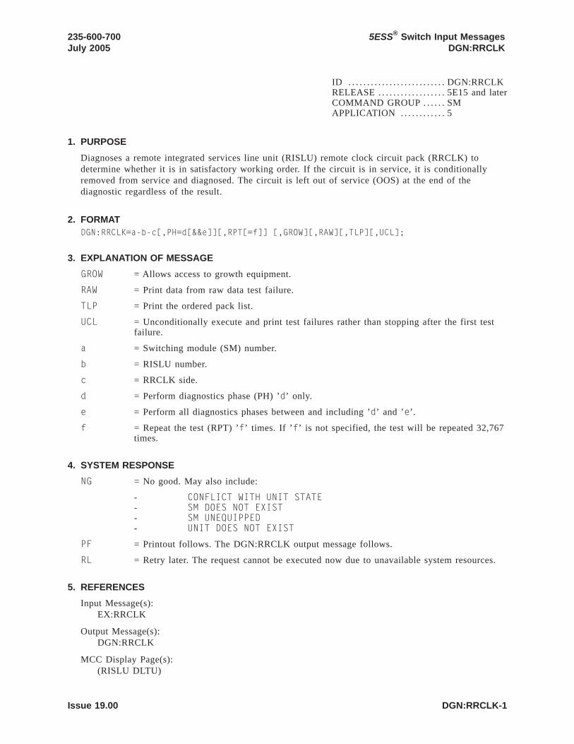
ID . . . . . . . . . . . . . . . . . . . . . . . . . . DGN:RRCLKRELEASE . . . . . . . . . . . . . . . . . . 5E15 and laterCOMMAND GROUP . . . . . . SMAPPLICATION . . . . . . . . . . . . 5
1. PURPOSE
Diagnoses a remote integrated services line unit (RISLU) remote clock circuit pack (RRCLK) todetermine whether it is in satisfactory working order. If the circuit is in service, it is conditionallyremoved from service and diagnosed. The circuit is left out of service (OOS) at the end of thediagnostic regardless of the result.
2. FORMATDGN:RRCLK=a-b-c[,PH=d[&&e]][,RPT[=f]] [,GROW][,RAW][,TLP][,UCL];
3. EXPLANATION OF MESSAGE
GROW = Allows access to growth equipment.
RAW = Print data from raw data test failure.
TLP = Print the ordered pack list.
UCL = Unconditionally execute and print test failures rather than stopping after the first testfailure.
a = Switching module (SM) number.
b = RISLU number.
c = RRCLK side.
d = Perform diagnostics phase (PH) ’d’ only.
e = Perform all diagnostics phases between and including ’d’ and ’e’.
f = Repeat the test (RPT) ’f’ times. If ’f’ is not specified, the test will be repeated 32,767times.
4. SYSTEM RESPONSE
NG = No good. May also include:
- CONFLICT WITH UNIT STATE- SM DOES NOT EXIST- SM UNEQUIPPED- UNIT DOES NOT EXIST
PF = Printout follows. The DGN:RRCLK output message follows.
RL = Retry later. The request cannot be executed now due to unavailable system resources.
5. REFERENCES
Input Message(s):EX:RRCLK
Output Message(s):DGN:RRCLK
MCC Display Page(s):(RISLU DLTU)
235-600-700July 2005
5ESS® Switch Input MessagesDGN:RRCLK
Issue 19.00 DGN:RRCLK-1


ID . . . . . . . . . . . . . . . . . . . . . . . . . . DGN:RVPTRELEASE . . . . . . . . . . . . . . . . . . 5E15 and laterCOMMAND GROUP . . . . . . SMAPPLICATION . . . . . . . . . . . . 5
1. PURPOSE
Requests that the revertive pulsing transceiver (RVPT) be diagnosed to determine whether it is insatisfactory working order. The circuit is left out of service when the testing is completed.
2. FORMATDGN:RVPT=a-b-c-d[,RAW][,UCL][,GROW][,RPT[=e]][,PH=f[&&g]][,TLP];
3. EXPLANATION OF MESSAGE
GROW = Allow access to growth equipment.
RAW = Print raw data from test failure.
TLP = Print the ordered pack list.
UCL = Perform all phases in the specified or implied range and print all test failures.
a = Switching module number.
b = Unit number.
c = Service group.
d = Circuit number.
e = Repeat the test ’e’ times. If ’e’ is not specified, the test will be repeated 32,767 times.If RPT is not specified, it runs once.
f = Perform diagnostic phase ’f’ only.
g = Perform all diagnostic phases between and including ’f’ and ’g’.
4. SYSTEM RESPONSE
NG = No good. The request has been denied. The message form is valid, but the requestconflicts with current status.
PF = Printout follows. The request was accepted. Followed by the DGN:RVPT outputmessage.
5. REFERENCES
Input Message(s):RST:RVPT
Output Message(s):DGN:RVPT
235-600-700July 2005
5ESS® Switch Input MessagesDGN:RVPT
Issue 19.00 DGN:RVPT-1


ID . . . . . . . . . . . . . . . . . . . . . . . . . . DGN:SASRELEASE . . . . . . . . . . . . . . . . . . 5E15 and laterCOMMAND GROUP . . . . . . SMAPPLICATION . . . . . . . . . . . . 5
1. PURPOSE
Removes and diagnoses a service announcement system (SAS) unit to determine whether it is insatisfactory working order. The unit is left out-of-service (OOS).
2. FORMATDGN:SAS=a-b[,RAW][,UCL][,RPT[=c]][,GROW][,PH=d[&&e]][,TLP];
3. EXPLANATION OF MESSAGE
GROW = Allow access to growth equipment.
RAW = Print raw test failure data.
TLP = Print the ordered pack list.
UCL = Unconditionally executes. DGN will continue past all non-fatal failures.
a = Switching module (SM) number. Refer to the APP:RANGES appendix in theAppendixes section of the Input Messages manual.
b = SAS unit number. Refer to the APP:RANGES appendix in the Appendixes section ofthe Input Messages manual.
c = The number of times the test is to be repeated. If ’c’ is not specified, the test will berepeated 32,767 times.
d = Number of the diagnostic phase(s) to be performed. If ’d’ is specified as a singlephase, only that phase will be performed. If ’d’ is specified as a range, ’d’ will be thefirst phase in that range to be performed.
e = Number of the last diagnostic phase in the range between and including ’d’ and ’e’ tobe performed.
4. SYSTEM RESPONSE
NG = No good. The request has been denied because it conflicts with current equipmentstatus. May also include:
- SM DOES NOT EXIST = The requested SM does not exist in the system.- SM UNEQUIPPED = The SM specified in the request is unequipped.- UNIT DOES NOT EXIST = The requested unit does not exist in the system.
PF = Printout follows. The request has been accepted. Followed by the DGN:SAS outputmessage.
RL = Retry later. The request cannot be executed now due to unavailable system resources.The message may be entered again later.
5. REFERENCES
Output Message(s):DGN:SASRST:SAS
Input Appendix(es):APP:RANGES
235-600-700July 2005
5ESS® Switch Input MessagesDGN:SAS
Issue 19.00 DGN:SAS-1

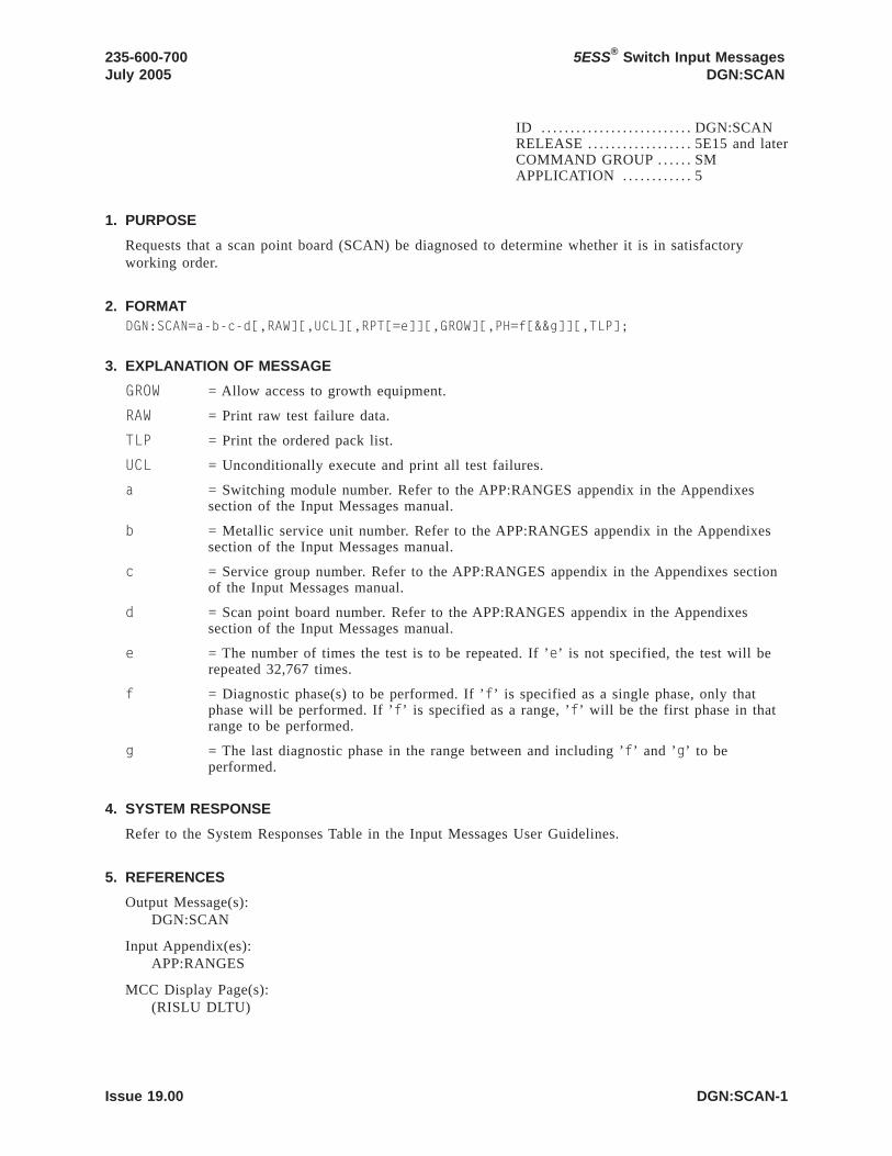
ID . . . . . . . . . . . . . . . . . . . . . . . . . . DGN:SCANRELEASE . . . . . . . . . . . . . . . . . . 5E15 and laterCOMMAND GROUP . . . . . . SMAPPLICATION . . . . . . . . . . . . 5
1. PURPOSE
Requests that a scan point board (SCAN) be diagnosed to determine whether it is in satisfactoryworking order.
2. FORMATDGN:SCAN=a-b-c-d[,RAW][,UCL][,RPT[=e]][,GROW][,PH=f[&&g]][,TLP];
3. EXPLANATION OF MESSAGE
GROW = Allow access to growth equipment.
RAW = Print raw test failure data.
TLP = Print the ordered pack list.
UCL = Unconditionally execute and print all test failures.
a = Switching module number. Refer to the APP:RANGES appendix in the Appendixessection of the Input Messages manual.
b = Metallic service unit number. Refer to the APP:RANGES appendix in the Appendixessection of the Input Messages manual.
c = Service group number. Refer to the APP:RANGES appendix in the Appendixes sectionof the Input Messages manual.
d = Scan point board number. Refer to the APP:RANGES appendix in the Appendixessection of the Input Messages manual.
e = The number of times the test is to be repeated. If ’e’ is not specified, the test will berepeated 32,767 times.
f = Diagnostic phase(s) to be performed. If ’f’ is specified as a single phase, only thatphase will be performed. If ’f’ is specified as a range, ’f’ will be the first phase in thatrange to be performed.
g = The last diagnostic phase in the range between and including ’f’ and ’g’ to beperformed.
4. SYSTEM RESPONSE
Refer to the System Responses Table in the Input Messages User Guidelines.
5. REFERENCES
Output Message(s):DGN:SCAN
Input Appendix(es):APP:RANGES
MCC Display Page(s):(RISLU DLTU)
235-600-700July 2005
5ESS® Switch Input MessagesDGN:SCAN
Issue 19.00 DGN:SCAN-1


ID . . . . . . . . . . . . . . . . . . . . . . . . . . DGN:SCSDCRELEASE . . . . . . . . . . . . . . . . . . 5E15 and laterCOMMAND GROUP . . . . . . AMAPPLICATION . . . . . . . . . . . . 5,3B
1. PURPOSE
Diagnoses the specified scanner and signal distributor controller (SCSDC).
Note: The input/output processor (IOP) must be in service before the SCSDC can be diagnosed.
2. FORMATDGN:SCSDC=a[:[RPT=b][,RAW][,UCL][,REX|,DEX]][:[PH=c[&&d]][,TLP][,CONT]];
3. EXPLANATION OF MESSAGE
CONT = Diagnoses only the specified controller. Units attached to the specified controller willnot be diagnosed.
DEX = Runs demand exercise phases in addition to routine exercise and normal (automatic)phases. This option will not allow special demand exercise phases that require userinteraction to be run even if the range of phases specified includes such a phase.
RAW = Prints the diagnostic results of every phase. The default is the first five failures of eachfailing phase.
REX = Runs routine exercise phases in addition to the normal (automatic) phases. This optionwill not allow demand exercise phases to be run even if the range of phases specifiedincludes such a phase.
TLP = Executes the trouble locating procedure (TLP) at the conclusion of the diagnostic. Thisprocess generates a list of suspected faulty equipment.
Note: The TLP and UCL parameters cannot be used together, as additional testresults may adversely affect the TLP listing.
UCL = Unconditional execution.
Note: This option does not override a forced early termination.
a = Member number.
b = Number of times the diagnostic is repeated. The maximum is 256. The default is one.
Note: This option does not override early terminations. UCL should also be specified ifthe diagnostic terminates.
c = Specifies the first phase to be executed.
d = Specifies the last phase to be executed.
4. SYSTEM RESPONSE
PF = Printout follows. Followed by the DGN:SCSDC output message.
5. REFERENCES
Input Message(s):OP:DMQRMV:SCSDCRST:IOPRST:SCSDC
235-600-700July 2005
5ESS® Switch Input MessagesDGN:SCSDC
Issue 19.00 DGN:SCSDC-1

STOP:DMQSTP:DMQ
Output Message(s):ANALY:TLPFILEDGN:SCSDCOP:DMQ-CMOP:DMQ-SMRST:IOP
Other Manual(s):
235-105-220 Corrective Maintenance
5ESS® Switch Input MessagesDGN:SCSDC
235-600-700July 2005
DGN:SCSDC-2 Issue 19.00

ID . . . . . . . . . . . . . . . . . . . . . . . . . . DGN:SDFIRELEASE . . . . . . . . . . . . . . . . . . 5E15 and laterCOMMAND GROUP . . . . . . SMAPPLICATION . . . . . . . . . . . . 5
1. PURPOSE
Requests that a SLC®96 digital facility interface (SDFI) circuit be removed and diagnosed. The circuitwill remain out of service (regardless of the diagnostic’s result) until a restore (RST) is requested.
The SDFI interfaces with SLC96 digital carrier line unit (DCLU) service groups. There are 4classes offaults associated with SDFI and DCLU circuits and they are written in the order in which they aremost likely to occur:
A = SDFI faults that are detected with SDFI diagnosis.
B = SDFI faults that are only detected by diagnosing a DCLU.
C = DCLU faults that are only detected with a SDFI diagnosis (any SDFI).
D = DCLU faults that are only detected by diagnosing a particular SDFI.
Fault recovery is unable to determine if detected problems are associated with bad SDFI or DCLUcircuits. Therefore fault recovery uses an algorithm in determining which circuits (SDFI or DCLU) todiagnose.
2. FORMATDGN:SDFI=a-b-c[,RAW][,UCL][,RPT[=d]][,GROW][,PH=e[&&f]][,TLP];
3. EXPLANATION OF MESSAGE
GROW = Allow access to growth equipment.
RAW = Print raw test results [all tests passed (ATP)/some tests failed (STF)] for each phaseexecuted.
TLP = Print the ordered suspect pack list if a test fails.
UCL = Unconditionally execute and print all test results requested rather than stopping on firstfailing phase.
a = Switching module (SM) number.
b = Digital carrier line unit (DCLU) number.
c = SDFI number.
d = The number of times the test is to be repeated. If ’d’ is not specified, the test will berepeated 32,767 times.
e = Diagnostic phase to be performed. If ’e’ is specified as a single phase, only that phasewill be performed. If ’e’ is specified in a range, ’e’ will be the first phase in that rangeto be performed.
f = The last diagnostic phase in the range between and including ’e’ and ’f’ to beperformed.
4. SYSTEM RESPONSE
NG = No good. The request has been denied. The message form is valid, but the requestconflicts with current status.
235-600-700July 2005
5ESS® Switch Input MessagesDGN:SDFI
Issue 19.00 DGN:SDFI-1

PF = Printout follows. The request was accepted. The DGN:SDFI output message followswhen the diagnostic is executed.
RL = Retry later. The request cannot be executed now due to unavailable system resources.
5. REFERENCES
Input Message(s):EX:SDFIRMV:SDFIRST:SDFISTP:SDFI
Output Message(s):DGN:SDFI
5ESS® Switch Input MessagesDGN:SDFI
235-600-700July 2005
DGN:SDFI-2 Issue 19.00

ID . . . . . . . . . . . . . . . . . . . . . . . . . . DGN:SDLCRELEASE . . . . . . . . . . . . . . . . . . 5E15 and laterCOMMAND GROUP . . . . . . AMAPPLICATION . . . . . . . . . . . . 5,3B
1. PURPOSE
Diagnoses the specified synchronous data link controller (SDLC).
Note: The input/output processor (IOP) must be in service before the SDLC can be diagnosed.
2. FORMATDGN:SDLC=a[:[RPT=b][,RAW][,UCL][,REX|,DEX]][:[PH=c[&&d]][,TLP] [,CONT]];
3. EXPLANATION OF MESSAGE
CONT = Diagnoses only the specified controller. Units attached to the specified controller willnot be diagnosed.
DEX = Runs demand exercise phases in addition to routine exercise and normal (automatic)phases. This option will not allow special demand exercise phases which require userinteraction to be run even if the range of phases specified includes such a phase.
RAW = Prints the diagnostic results of every phase. The default is the first five failures of eachfailing phase.
REX = Runs routine exercise phases in addition to the normal (automatic) phases. This optionwill not allow demand exercise phases to be run even if the range of phases specifiedincludes such a phase.
TLP = Executes the trouble locating procedure (TLP) at the conclusion of the diagnostic. Thisprocess generates a list of suspected faulty equipment.
UCL = Unconditional execution.
Note: This option does not override a forced early termination.
Note: The TLP and UCL parameters cannot be used together, as additionaltest results may adversely affect the TLP listing.
a = Member number.
b = Number of times the diagnostic is repeated. The maximum is 256. The default is one.
Note: This option does not override early terminations. UCL should also be specified ifthe diagnostic terminates.
c = Specifies the first phase to be executed.
d = Specifies the last phase to be executed.
4. SYSTEM RESPONSE
PF = Printout follows. Followed by the DGN:SDLC output message.
5. REFERENCES
Input Message(s):OP:DMQRMV:SDLCRST:IOPRST:SDLC
235-600-700July 2005
5ESS® Switch Input MessagesDGN:SDLC
Issue 19.00 DGN:SDLC-1

STOP:DMQSTP:DMQ
Output Message(s):ANALY:TLPFILEDGN:SDLCOP:DMQ-CMOP:DMQ-SMRST:IOP
Other Manual(s):
235-105-220 Corrective Maintenance
5ESS® Switch Input MessagesDGN:SDLC
235-600-700July 2005
DGN:SDLC-2 Issue 19.00

ID . . . . . . . . . . . . . . . . . . . . . . . . . . DGN:SFIRELEASE . . . . . . . . . . . . . . . . . . 5E15 and laterCOMMAND GROUP . . . . . . SMAPPLICATION . . . . . . . . . . . . 5
1. PURPOSE
Requests that diagnostics be executed on a digital networking unit - synchronous optical network(DNU-S) synchronous transport signal electrical interface (STSX-1) facility interface (SFI).
2. FORMATDGN:SFI=a-b-c-d[,PH=e[&&f]][,RPT [=g]][,GROW][,RAW][,TLP][,UCL];
3. EXPLANATION OF MESSAGE
GROW = Allows access to growth equipment.
RAW = Print data from raw data test failure.
TLP = Print the ordered pack list if a test fails.
UCL = Execute and print all test failures unconditionally rather than stopping after the firsttest failure.
a = Switching module (SM) number. Refer to the APP:RANGES appendix in theAppendixes section of the Input Messages manual.
b = DNU-S number. Refer to the APP:RANGES appendix in the Appendixes section of theInput Messages manual.
c = Data group number. Refer to the APP:RANGES appendix in the Appendixes section ofthe Input Messages manual.
d = STSX-1 facility interface number. Refer to the APP:RANGES appendix in theAppendixes section of the Input Messages manual.
e = The number of the phase to be run, or the lower limit of a range of phases.
f = The upper limit of a range of phases to be run.
g = The number of times the diagnostic phases are to be repeated (1-32676). If variable ’g’is not specified, the phases will be repeated 32,767 times.
4. SYSTEM RESPONSE
NG = No good. The message form is valid, but the request conflicts with the current status.
PF = Printout follows. The DGN:SFI output message follows.
RL = Retry later. The request cannot be executed now due to unavailable system resources.
5. REFERENCES
Input Message(s):OP:DMQRST:SFISTP:SFI
Output Message(s):DGN:SFI
235-600-700July 2005
5ESS® Switch Input MessagesDGN:SFI
Issue 19.00 DGN:SFI-1

Input Appendix(es):APP:RANGES
MCC Display Page(s):1510 (DNUS STATUS)
5ESS® Switch Input MessagesDGN:SFI
235-600-700July 2005
DGN:SFI-2 Issue 19.00

ID . . . . . . . . . . . . . . . . . . . . . . . . . . DGN:SLIMRELEASE . . . . . . . . . . . . . . . . . . 5E15 and laterCOMMAND GROUP . . . . . . SMAPPLICATION . . . . . . . . . . . . 5
1. PURPOSE
Requests that a subscriber line instrument measurement (SLIM) board be diagnosed to determinewhether it is in satisfactory working order.
2. FORMATDGN:SLIM=a-b-c-d[,RAW][,UCL][,RPT[=e]][,GROW][,PH=f[&&g]][,TLP];
3. EXPLANATION OF MESSAGE
GROW = Allow access to growth equipment.
RAW = Print raw test failure data.
TLP = Print the ordered pack list.
UCL = Unconditionally execute and print all test failures.
a = Switching module number. Refer to the APP:RANGES appendix in the Appendixessection of the Input Messages manual.
b = Metallic service unit number. Refer to the APP:RANGES appendix in the Appendixessection of the Input Messages manual.
c = Service group number. Refer to the APP:RANGES appendix in the Appendixes sectionof the Input Messages manual.
d = SLIM board number. Refer to the APP:RANGES appendix in the Appendixes section ofthe Input Messages manual.
e = The number of times the test is to be repeated. If ’e’ is not specified, the test will berepeated 32,767 times.
f = Diagnostic phase(s) to be performed. If ’f’ is specified as a single phase, only thatphase will be performed. If variable ’f’ is specified as a range, ’f’ will be the first phasein that range to be performed.
g = The last diagnostic phase in the range between and including ’f’ and ’g’ to beperformed.
4. SYSTEM RESPONSE
None.
5. REFERENCES
Output Message(s):DGN:SLIM
Input Appendix(es):APP:RANGES
MCC Display Page(s):(RISLU DLTU)
235-600-700July 2005
5ESS® Switch Input MessagesDGN:SLIM
Issue 19.00 DGN:SLIM-1


ID . . . . . . . . . . . . . . . . . . . . . . . . . . DGN:TACRELEASE . . . . . . . . . . . . . . . . . . 5E15 and laterCOMMAND GROUP . . . . . . SMAPPLICATION . . . . . . . . . . . . 5
1. PURPOSE
Requests that a test and access circuit (TAC) be diagnosed to determine whether it is in satisfactoryworking order.
2. FORMATDGN:TAC=a-b-c[,RAW][,UCL][,RPT[=d]][,GROW][,PH=e[&&f]][,TLP];
3. EXPLANATION OF MESSAGE
GROW = Allow access to growth equipment.
RAW = Print raw test failure data.
TLP = Print the ordered pack list.
UCL = Unconditionally execute and print all test failures.
a = Switching module number. Refer to the APP:RANGES appendix in the Appendixessection of the Input Messages manual.
b = Trunk unit number. Refer to the APP:RANGES appendix in the Appendixes section ofthe Input Messages manual.
c = Service group number. Refer to the APP:RANGES appendix in the Appendixes sectionof the Input Messages manual.
d = The number of times the test is to be repeated. If ’d’ is not specified, the test will berepeated 32,767 times.
e = Diagnostic phase(s) to be performed. If ’e’ is specified as a single phase, only thatphase will be performed. If ’e’ is specified as a range, ’e’ will be the first phase in thatrange to be performed.
f = The last diagnostic phase in the range between and including ’e’ and ’f’ to beperformed.
4. SYSTEM RESPONSE
NG = No good. Input request not valid.
PF = Printout follows. Followed by the DGN:TAC output message.
5. REFERENCES
Output Message(s):DGN:TAC
Input Appendix(es):APP:RANGES
235-600-700July 2005
5ESS® Switch Input MessagesDGN:TAC
Issue 19.00 DGN:TAC-1


ID . . . . . . . . . . . . . . . . . . . . . . . . . . DGN:TENRELEASE . . . . . . . . . . . . . . . . . . 5E15 and laterCOMMAND GROUP . . . . . . SMAPPLICATION . . . . . . . . . . . . 5
1. PURPOSE
Requests that a trunk equipment number (TEN) be diagnosed to determine whether it is in satisfactoryworking order.
2. FORMATDGN:TEN=a-b-c-d-e[,RAW][,UCL][,RPT[=f]][,GROW][,PH=g[&&h]][,TLP];
3. EXPLANATION OF MESSAGE
GROW = Allow access to growth equipment.
RAW = Print raw test failure data.
TLP = Print the ordered pack list.
UCL = Unconditionally execute and print all test failures.
a = Switching module number. Refer to the APP:RANGES appendix in the Appendixessection of the Input Messages manual.
b = TEN unit number. Refer to the APP:RANGES appendix in the Appendixes section ofthe Input Messages manual.
c = Service group number. Refer to the APP:RANGES appendix in the Appendixes sectionof the Input Messages manual.
d = TEN board number. Refer to the APP:RANGES appendix in the Appendixes section ofthe Input Messages manual.
e = TEN circuit number. Refer to the APP:RANGES appendix in the Appendixes section ofthe Input Messages manual.
f = The number of times the test is to be repeated. If ’f’ is not specified, the test will berepeated 32,767 times.
g = Diagnostic phase(s) to be performed. If ’g’ is specified as a single phase, only thatphase will be performed. If ’g’ is specified as a range, ’g’ will be the first phase in thatrange to be performed.
h = The last diagnostic phase in the range between and including ’g’ and ’h’ to beperformed.
4. SYSTEM RESPONSE
NG = No good. Input request not valid.
PF = Printout follows. Followed by the DGN:TEN output message.
5. REFERENCES
Output Message(s):DGN:TEN
Input Appendix(es):APP:RANGES
235-600-700July 2005
5ESS® Switch Input MessagesDGN:TEN
Issue 19.00 DGN:TEN-1


ID . . . . . . . . . . . . . . . . . . . . . . . . . . DGN:TMSFPRELEASE . . . . . . . . . . . . . . . . . . 5E16(2) and laterCOMMAND GROUP . . . . . . CMAPPLICATION . . . . . . . . . . . . 5
1. PURPOSE
Requests diagnostics for the time multiplexed switch (TMS) fabric pair (TMSFP) on the specifiedoffice network and timing complex (ONTC). Completion of this input message leaves the unit in theout-of-service (OOS) state.
If the unit is not OOS, the system will first remove the unit conditionally.
2. FORMATDGN:TMSFP=a-b,[TMSLNK=c[&&d]][,RAW][,UCL][,RPT[=e]][,PH=f[&&g]][,TLP][,GROW];
3. EXPLANATION OF MESSAGE
GROW = Allows access to growth equipment.
RAW = Print raw test failure data.
TLP = Print the ordered suspected pack list if a test fails.
UCL = Continue to print all test results unconditionally rather than just printing the first failingtest.
a = ONTC side that the TMSFP is on.
b = TMS fabric pair number.
c = TMS link number to start diagnostic from. Used only with diagnostic phases 4 and 5. Ifit’s the only range limit specified then it’s the only TMS link to be diagnosed. If neitherrange limit specified then the whole range of 4-371 is implied.
d = Ending number of the TMSLNK range to be diagnosed.
e = The number of times the test is to be repeated (RPT). If ’e’ is not specified, the testwill be repeated 32,767 times.
f = The number of the phase (PH) to be executed, or the lower limit in a range of phases.
g = Upper limit in a range of phases.
4. SYSTEM RESPONSE
NG = No good. The request has been denied. The message syntax is valid, but the requestcould not be processed. Refer to the APP:CM-IM-REASON appendix in the Appendixessection of the Input Messages manual for a list of possible reasons for denying therequest.
PF = Printout follows. A DGN:TMSFP output message will follow in response to the request.
RL = Retry later. The request cannot be executed now due to unavailable system resources.
5. REFERENCES
Input Message(s):ABT:TMSFPOP:CFGSTATOP:DMQ-CM-SM
235-600-700July 2005
5ESS® Switch Input MessagesDGN:TMSFP
Issue 19.00 DGN:TMSFP-1

STP:TMSFP
Output Message(s):DGN:TMSFPOP:CFGSTATOP:DMQ-CM
Input Appendix(es):APP:CM-IM-REASON
Other Manual(s):
235-105-210 Routine Operations and Maintenance235-105-220 Corrective Maintenance
MCC Display Page(s):
1212 TMS FABRIC PAIR STATUS1214 QLPS SUMMARY1220,b TMS LINK SUMMARY (where b=TMSFP number)
5ESS® Switch Input MessagesDGN:TMSFP
235-600-700July 2005
DGN:TMSFP-2 Issue 19.00

ID . . . . . . . . . . . . . . . . . . . . . . . . . . DGN:TMSRELEASE . . . . . . . . . . . . . . . . . . 5E15 and laterCOMMAND GROUP . . . . . . CMAPPLICATION . . . . . . . . . . . . 5
1. PURPOSE
Requests that the time multiplex switch (TMS) in the specified office network and timing complex(ONTC) be diagnosed. This command is not applicable in Communication Module 3 (CM3) office.
2. FORMATDGN:TMS=a[,RAW][,UCL][,RPT[=b]][,PH=c[&&d]][,TLP][,HELPER=e][,GROW];
3. EXPLANATION OF MESSAGE
GROW = Allows access to growth equipment.
RAW = Print raw test failure data.
TLP = Print the ordered suspected pack list if a test fails.
UCL = Print all test results unconditionally rather than just printing the first failing test.
a = TMS side.
b = Number of times the diagnostic is to be repeated (RPT) (default 32,767).
c = The number of the phase (PH) to be executed, or the lower limit in a range of phases.
d = Upper limit in a range of phases.
e = The number of the foundation peripheral controller (FPC) side to be used as a ’helper’unit for the diagnostic. If this option is not input, the standby FPC will be used.
4. SYSTEM RESPONSE
NG = No good. The request has been denied. The message syntax is valid, but the requestcould not be processed.
PF = Printout follows. Followed by the DGN:TMS output message.
RL = Retry later. The request cannot be executed now.
5. REFERENCES
Input Message(s):ABT:TMSSTP:TMS
Output Message(s):DGN:TMS
Input Appendix(es):APP:CM-IM-REASON
Other Manual(s):
235-105-210 Routine Operations and Maintenance235-105-220 Corrective Maintenance
235-600-700July 2005
5ESS® Switch Input MessagesDGN:TMS
Issue 19.00 DGN:TMS-1


ID . . . . . . . . . . . . . . . . . . . . . . . . . . DGN:TMUXRELEASE . . . . . . . . . . . . . . . . . . 5E15 and laterCOMMAND GROUP . . . . . . SMAPPLICATION . . . . . . . . . . . . 5
1. PURPOSE
Requests that diagnostics be executed on a digital networking unit - synchronous optical network(DNU-S) transmission multiplexer (TMUX).
2. FORMATDGN:TMUX=a-b-c-d[,PH=e[&&f]][,RPT [=g]][,GROW][,RAW][,TLP][,UCL];
3. EXPLANATION OF MESSAGE
GROW = Allows access to growth equipment.
RAW = Print data from raw data test failure.
TLP = Print the ordered pack list if a test fails.
UCL = Execute and print all test failures unconditionally rather than stopping after the firsttest failure.
a = Switching module (SM) number. Refer to the APP:RANGES appendix in theAppendixes section of the Input Messages manual.
b = DNU-S number. Refer to the APP:RANGES appendix in the Appendixes section of theInput Messages manual.
c = Data group number. Refer to the APP:RANGES appendix in the Appendixes section ofthe Input Messages manual.
d = TMUX number. Refer to the APP:RANGES appendix in the Appendixes section of theInput Messages manual.
e = The number of the phase to be run, or the lower limit of a range of phases.
f = The upper limit of a range of phases to be run.
g = The number of times the diagnostic phases are to be repeated (1-32676). If variable ’g’is not specified, the phases will be repeated 32,767 times.
4. SYSTEM RESPONSE
NG = No good. The message form is valid, but the request conflicts with the current status.
PF = Printout follows. The DGN:TMUX output message follows.
RL = Retry later. The request cannot be executed now due to unavailable system resources.
5. REFERENCES
Input Message(s):OP:DMQRST:TMUXSTP:TMUX
Output Message(s):DGN:TMUX
235-600-700July 2005
5ESS® Switch Input MessagesDGN:TMUX
Issue 19.00 DGN:TMUX-1

Input Appendix(es):APP:RANGES
MCC Display Page(s):1510 (DNUS STATUS)
5ESS® Switch Input MessagesDGN:TMUX
235-600-700July 2005
DGN:TMUX-2 Issue 19.00

ID . . . . . . . . . . . . . . . . . . . . . . . . . . DGN:TTFCOMRELEASE . . . . . . . . . . . . . . . . . . 5E15 and laterCOMMAND GROUP . . . . . . SMAPPLICATION . . . . . . . . . . . . 5
1. PURPOSE
Requests that a transmission test facility common (TTFCOM) circuit be diagnosed to determinewhether it is in satisfactory working order.
2. FORMATDGN:TTFCOM=a-b-c-d[,RAW][,UCL][,RPT[=e]][,GROW][,PH=f[&&g]][,TLP];
3. EXPLANATION OF MESSAGE
GROW = Allow access to growth equipment.
RAW = Print raw test failure data.
TLP = Print the ordered pack list.
UCL = Unconditionally execute and print all test failures.
a = Switching module number. Refer to the APP:RANGES appendix in the Appendixessection of the Input Messages manual.
b = Global digital service unit number. Refer to the APP:RANGES appendix in theAppendixes section of the Input Messages manual.
c = Service group number. Refer to the APP:RANGES appendix in the Appendixes sectionof the Input Messages manual.
d = Board number. Refer to the APP:RANGES appendix in the Appendixes section of theInput Messages manual.
e = The number of times the test is to be repeated. If ’e’ is not specified, the test will berepeated 32,767 times.
f = Diagnostic phase(s) to be performed. If ’f’ is specified as a single phase, only thatphase will be performed. If ’f’ is specified as a range, ’f’ will be the first phase in thatrange to be performed.
g = The last diagnostic phase in the range between and including ’f’ and ’g’ to beperformed.
4. SYSTEM RESPONSE
NG = No good. The request has been denied. The message form is valid, but the requestconflicts with current status.
PF = Printout follows. The request was accepted. Followed by the DGN:TTFCOM outputmessage.
5. REFERENCES
Output Message(s):DGN:TTFCOM
Input Appendix(es):APP:RANGES
235-600-700July 2005
5ESS® Switch Input MessagesDGN:TTFCOM
Issue 19.00 DGN:TTFCOM-1


ID . . . . . . . . . . . . . . . . . . . . . . . . . . DGN:TTYCRELEASE . . . . . . . . . . . . . . . . . . 5E15 and laterCOMMAND GROUP . . . . . . AMAPPLICATION . . . . . . . . . . . . 5,3B
1. PURPOSE
Diagnoses the specified teletypewriter controller (TTYC).
Note: The input/output processor (IOP) must be in service before the TTYC can be diagnosed.
2. FORMATDGN:TTYC=a[:[,RPT=b][,RAW][,UCL][,REX|,DEX]][,PH=c[&&d]][,TLP][,CONT];
3. EXPLANATION OF MESSAGE
CONT = Includes only the specified unit (controller). Units attached to the specified unit willnot be included. If the specified unit has no attached units, CONT is ignored.
DEX = Runs demand exercise phases in addition to routine exercise and normal (automatic)phases. This option will not allow special demand exercise phases that require userinteraction to be run even if the range of phases specified includes such a phase.
RAW = Prints the diagnostic results of every phase. The default is the first five failures of eachfailing phase.
REX = Runs routine exercise phases in addition to the normal (automatic) phases. This optionwill not allow demand exercise phases to be run even if the range of phases specifiedincludes such a phase.
TLP = Executes the trouble locating procedure (TLP) at the conclusion of the diagnostic. Thisprocess generates a list of suspected faulty equipment.
Note: The TLP and UCL parameters cannot be used together, as additional test resultsmay adversely affect the TLP listing.
UCL = Unconditional execution.
Note: This option does not override a forced early termination.
a = Member number.
b = Number of times the diagnostic is to be repeated. The maximum is 256. The default isone.
Note: This option does not override early terminations. UCL should also be specified ifthe diagnostic terminates.
c = Specifies the first phase to be executed.
d = Specifies the last phase to be executed.
4. SYSTEM RESPONSE
PF = Printout follows. Followed by the DGN:TTYC output message.
5. REFERENCES
Input Message(s):OP:DMQRMV:TTYC
235-600-700July 2005
5ESS® Switch Input MessagesDGN:TTYC
Issue 19.00 DGN:TTYC-1

RST:TTYCSTOP:DMQSTP:DMQ
Output Message(s):ANALY:TLPFILEDGN:TTYCOP:DMQ-CMOP:DMQ-SM
Other Manual(s):
235-105-220 Corrective Maintenance
5ESS® Switch Input MessagesDGN:TTYC
235-600-700July 2005
DGN:TTYC-2 Issue 19.00

ID . . . . . . . . . . . . . . . . . . . . . . . . . . DGN:TUCHBDRELEASE . . . . . . . . . . . . . . . . . . 5E15 and laterCOMMAND GROUP . . . . . . SMAPPLICATION . . . . . . . . . . . . 5
1. PURPOSE
Requests that a trunk unit channel board (TUCHBD) be diagnosed to determine whether it is insatisfactory working order.
2. FORMATDGN:TUCHBD=a-b-c-d[,RAW][,UCL][,RPT[=e]][,GROW][,PH=f[&&g]][,TLP];
3. EXPLANATION OF MESSAGE
GROW = Allow access to growth equipment.
RAW = Print raw test failure data.
TLP = Print the ordered pack list.
UCL = Unconditionally execute and print all test failures.
a = Switching module number. Refer to the APP:RANGES appendix in the Appendixessection of the Input Messages manual.
b = Trunk unit number. Refer to the APP:RANGES appendix in the Appendixes section ofthe Input Messages manual.
c = Service group number. Refer to the APP:RANGES appendix in the Appendixes sectionof the Input Messages manual.
d = Channel board number. Refer to the APP:RANGES appendix in the Appendixes sectionof the Input Messages manual.
e = The number of times the test is to be repeated. If ’e’ is not specified, the test will berepeated 32,767 times.
f = Diagnostic phase(s) to be performed. If ’f’ is specified as a single phase, only thatphase will be performed. If ’f’ is specified as a range, ’f’ will be the first phase in thatrange to be performed.
g = The last diagnostic phase in the range between and including ’f’ and ’g’ to beperformed.
4. SYSTEM RESPONSE
NG = No good. The request has been denied. The message form is valid, but the requestconflicts with current status.
PF = Printout follows. The request was accepted. Followed by the DGN:TUCHBD outputmessage.
5. REFERENCES
Output Message(s):DGN:TUCHBD
Input Appendix(es):APP:RANGES
235-600-700July 2005
5ESS® Switch Input MessagesDGN:TUCHBD
Issue 19.00 DGN:TUCHBD-1


ID . . . . . . . . . . . . . . . . . . . . . . . . . . DGN:UCONFRELEASE . . . . . . . . . . . . . . . . . . 5E15 and laterCOMMAND GROUP . . . . . . SMAPPLICATION . . . . . . . . . . . . 5
1. PURPOSE
Requests that a universal conference (UCONF) circuit board be diagnosed to determine whether it is insatisfactory working order.
2. FORMATDGN:UCONF=a-b-c-d[,RAW][,UCL][,RPT[=e]][,GROW][,PH=f[&&g]][,TLP];
3. EXPLANATION OF MESSAGE
GROW = Allow access to growth equipment.
RAW = Print raw test failure data.
TLP = Print the ordered pack list.
UCL = Unconditionally execute and print all test failures.
a = Switching module number. Refer to the APP:RANGES appendix in the Appendixessection of the Input Messages manual.
b = Global digital service unit number. Refer to the APP:RANGES appendix in theAppendixes section of the Input Messages manual.
c = Service group number. Refer to the APP:RANGES appendix in the Appendixes sectionof the Input Messages manual.
d = Digital service circuit unit board number. Refer to the APP:RANGES appendix in theAppendixes section of the Input Messages manual.
e = The number of times the test is to be repeated. If ’e’ is not specified, the test will berepeated 32,767 times.
f = Diagnostic phase(s) to be performed. If ’f’ is specified as a single phase, only thatphase will be performed. If ’f’ is specified as a range, ’f’ will be the first phase in thatrange to be performed.
g = The last diagnostic phase in the range between and including ’f’ and ’g’ to beperformed.
4. SYSTEM RESPONSE
NG = No good. The request has been denied. The message form is valid, but the requestconflicts with current status.
PF = Printout follows. The request was accepted. Followed by the DGN:UCONF outputmessage.
5. REFERENCES
Output Message(s):DGN:UCONF
Input Appendix(es):APP:RANGES
235-600-700July 2005
5ESS® Switch Input MessagesDGN:UCONF
Issue 19.00 DGN:UCONF-1


ID . . . . . . . . . . . . . . . . . . . . . . . . . . DGN:UTDRELEASE . . . . . . . . . . . . . . . . . . 5E15 and laterCOMMAND GROUP . . . . . . SMAPPLICATION . . . . . . . . . . . . 5
1. PURPOSE
Requests that a universal tone decoder (UTD) board be diagnosed to determine if it is in satisfactoryworking order.
2. FORMATDGN:UTD=a-b-c-d[,RAW][,UCL][,RPT[=e]][,GROW][,PH=f[&&g]][,TLP];
3. EXPLANATION OF MESSAGE
GROW = Allow access to growth equipment.
RAW = Print raw test failure data.
TLP = Print the ordered pack list.
UCL = Unconditionally execute and print all test failures.
a = Switching module (SM) number. Refer to the APP:RANGES appendix in theAppendixes section of the Input Messages manual.
b = Local digital service unit (DSU) number. Refer to the APP:RANGES appendix in theAppendixes section of the Input Messages manual.
c = Service group number. Refer to the APP:RANGES appendix in the Appendixes sectionof the Input Messages manual.
d = DSU board position number. Refer to the APP:RANGES appendix in the Appendixessection of the Input Messages manual.
e = The number of times the test is to be repeated. If ’e’ is not specified, the test will berepeated 32,767 times.
f = Diagnostic phase(s) to be performed. If ’f’ is specified as a single phase, only thatphase will be performed. If ’f’ is specified as a range, ’f’ will be the first phase in thatrange to be performed.
g = The last diagnostic phase in the range between and including ’f’ and ’g’ to beperformed.
4. SYSTEM RESPONSE
NG = No good. Input request not valid.
PF = Printout follows. Followed by the DGN:UTD output message.
5. REFERENCES
Output Message(s):DGN:UTD
Input Appendix(es):APP:RANGES
235-600-700July 2005
5ESS® Switch Input MessagesDGN:UTD
Issue 19.00 DGN:UTD-1


ID . . . . . . . . . . . . . . . . . . . . . . . . . . DGN:UTGRELEASE . . . . . . . . . . . . . . . . . . 5E15 and laterCOMMAND GROUP . . . . . . SMAPPLICATION . . . . . . . . . . . . 5
1. PURPOSE
Requests that a universal tone generator (UTG) board be diagnosed to determine if it is in satisfactoryworking order.
2. FORMATDGN:UTG=a-b-c-d[,RAW][,UCL][,RPT[=e]][,GROW][,PH=f[&&g]][,TLP];
3. EXPLANATION OF MESSAGE
GROW = Allow access to growth equipment.
RAW = Print raw test failure data.
TLP = Print the ordered pack list.
UCL = Unconditionally execute and print all test failures.
a = Switching module (SM) number. Refer to the APP:RANGES appendix in theAppendixes section of the Input Messages manual.
b = Local digital service unit (DSU) number. Refer to the APP:RANGES appendix in theAppendixes section of the Input Messages manual.
c = Service group number. Refer to the APP:RANGES appendix in the Appendixes sectionof the Input Messages manual.
d = DSU board position number. Refer to the APP:RANGES appendix in the Appendixessection of the Input Messages manual.
e = The number of times the test is to be repeated. If ’e’ is not specified, the test will berepeated 32,767 times.
f = Diagnostic phase(s) to be performed. If ’f’ is specified as a single phase, only thatphase will be performed. If ’f’ is specified as a range, ’f’ will be the first phase in thatrange to be performed.
g = The last diagnostic phase in the range between and including ’f’ and ’g’ to beperformed.
4. SYSTEM RESPONSE
NG = No good. The request has been denied. The message form is valid, but the requestconflicts with current status.
PF = Printout follows. The request was accepted. Followed by the DGN:UTG outputmessage.
5. REFERENCES
Output Message(s):DGN:UTG
Input Appendix(es):APP:RANGES
235-600-700July 2005
5ESS® Switch Input MessagesDGN:UTG
Issue 19.00 DGN:UTG-1


ID . . . . . . . . . . . . . . . . . . . . . . . . . . DISC:WSLINERELEASE . . . . . . . . . . . . . . . . . . 5E15 and laterCOMMAND GROUP . . . . . . TRKLNAPPLICATION . . . . . . . . . . . . 5
1. PURPOSE
Requests that the line that is associated with the specified trunk and line work station (TLWS) testposition (TP) be disconnected. The association was accomplished earlier using a CONN:WSLINE orCONN:WSIC input message. If tests are ongoing, they are automatically cancelled.
2. FORMATDISC:WSLINE,TP=a;
3. EXPLANATION OF MESSAGE
a = TLWS TP number.
4. SYSTEM RESPONSE
NG = No good. Refer to the APP:TLWS appendix in the Appendixes section of the OutputMessages manual for an explanation of TLWS error responses.
OK = Good. The line was released.
5. REFERENCES
Input Message(s):CONN:WSICCONN:WSLINESET:WSPOS
Output Appendix(es):APP:TLWS
Other Manual(s):
235-100-125 System Description235-105-110 System Maintenance Requirements and Tools235-105-220 Corrective Maintenance
MCC Display Page(s):160 (TRUNK & LINE MAINT)
235-600-700July 2005
5ESS® Switch Input MessagesDISC:WSLINE
Issue 19.00 DISC:WSLINE-1


ID . . . . . . . . . . . . . . . . . . . . . . . . . . DISC:WSPHONERELEASE . . . . . . . . . . . . . . . . . . 5E15 and laterCOMMAND GROUP . . . . . . TRKLNAPPLICATION . . . . . . . . . . . . 5
1. PURPOSE
Requests that the trunk and line work station (TLWS) talk-and-monitor (T&M) phone be disconnectedfrom the indicated test position (TP). A TLWS TP must have already been selected using theSET:WSPOS input message.
2. FORMATDISC:WSPHONE,TP=a;
3. EXPLANATION OF MESSAGE
a = TLWS TP number.
4. SYSTEM RESPONSE
NG = No good. Refer to the APP:TLWS appendix in the Appendixes section of the OutputMessages manual for an explanation of TLWS error responses.
OK = Good. The T&M phone was released.
5. REFERENCES
Input Message(s):CONN:WSPHONESET:WSPHONESET:WSPOSTST:WSMEASTST:WSMETTST:WSMNTRTST:WSSENDTST:WSSUPV
Output Appendix(es):APP:TLWS
Other Manual(s):
235-100-125 System Description235-105-110 System Maintenance Requirements and Tools235-105-220 Corrective Maintenance
MCC Display Page(s):160 (TRUNK & LINE MAINT)
235-600-700July 2005
5ESS® Switch Input MessagesDISC:WSPHONE
Issue 19.00 DISC:WSPHONE-1


ID . . . . . . . . . . . . . . . . . . . . . . . . . . DISC:WSPORT-ARELEASE . . . . . . . . . . . . . . . . . . 5E15 - 5E16(1)COMMAND GROUP . . . . . . TRKLNAPPLICATION . . . . . . . . . . . . 5
1. PURPOSE
Requests that the port (line or trunk) that is associated with the specified trunk and line work station(TLWS) test position (TP) be disconnected. The association was accomplished earlier using aCONN:WSLINE, CONN:WSPORT, CONN:WSTRK or CONN:WSIC input message. If tests areongoing, they are automatically cancelled.
2. FORMATDISC:WSPORT,TP=a;
3. EXPLANATION OF MESSAGE
a = TLWS TP number.
4. SYSTEM RESPONSE
NG = No good. Refer to the APP:TLWS appendix in the Appendixes section of the OutputMessages Manual for an explanation of TLWS error responses.
OK = Good. The port was released.
5. REFERENCES
Input Message(s):CONN:WSICCONN:WSLINECONN:WSPORTCONN:WSTRKSET:WSPOS
Output Appendix(es):APP:TLWS
Other Manual(s):
235-100-125 System Description235-105-110 System Maintenance Requirements and Tools235-105-220 Corrective Maintenance
MCC Display Page(s):160 (TRUNK & LINE MAINT)
235-600-700July 2005
5ESS® Switch Input MessagesDISC:WSPORT
Issue 19.00 DISC:WSPORT-A-1


ID . . . . . . . . . . . . . . . . . . . . . . . . . . DISC:WSPORT-BRELEASE . . . . . . . . . . . . . . . . . . 5E16(2) and laterCOMMAND GROUP . . . . . . TRKLNAPPLICATION . . . . . . . . . . . . 5
1. PURPOSE
Requests that the port [line, trunk or signaling data link (SDL)] that is associated with the specifiedtrunk and line work station (TLWS) test position (TP) be disconnected. The association wasaccomplished earlier using a CONN:WSLINE, CONN:WSPORT, CONN:WSTRK or CONN:WSICinput message. If tests are ongoing, they are automatically cancelled.
2. FORMATDISC:WSPORT,TP=a;
3. EXPLANATION OF MESSAGE
a = TLWS TP number.
4. SYSTEM RESPONSE
NG = No good. Refer to the APP:TLWS appendix in the Appendixes section of the OutputMessages Manual for an explanation of TLWS error responses.
OK = Good. The port was released.
5. REFERENCES
Input Message(s):CONN:WSICCONN:WSLINECONN:WSPORTCONN:WSTRKSET:WSPOS
Output Appendix(es):APP:TLWS
Other Manual(s):
235-100-125 System Description235-105-110 System Maintenance Requirements and Tools235-105-220 Corrective Maintenance
MCC Display Page(s):
160 TRUNK & LINE MAINT
235-600-700July 2005
5ESS® Switch Input MessagesDISC:WSPORT
Issue 19.00 DISC:WSPORT-B-1

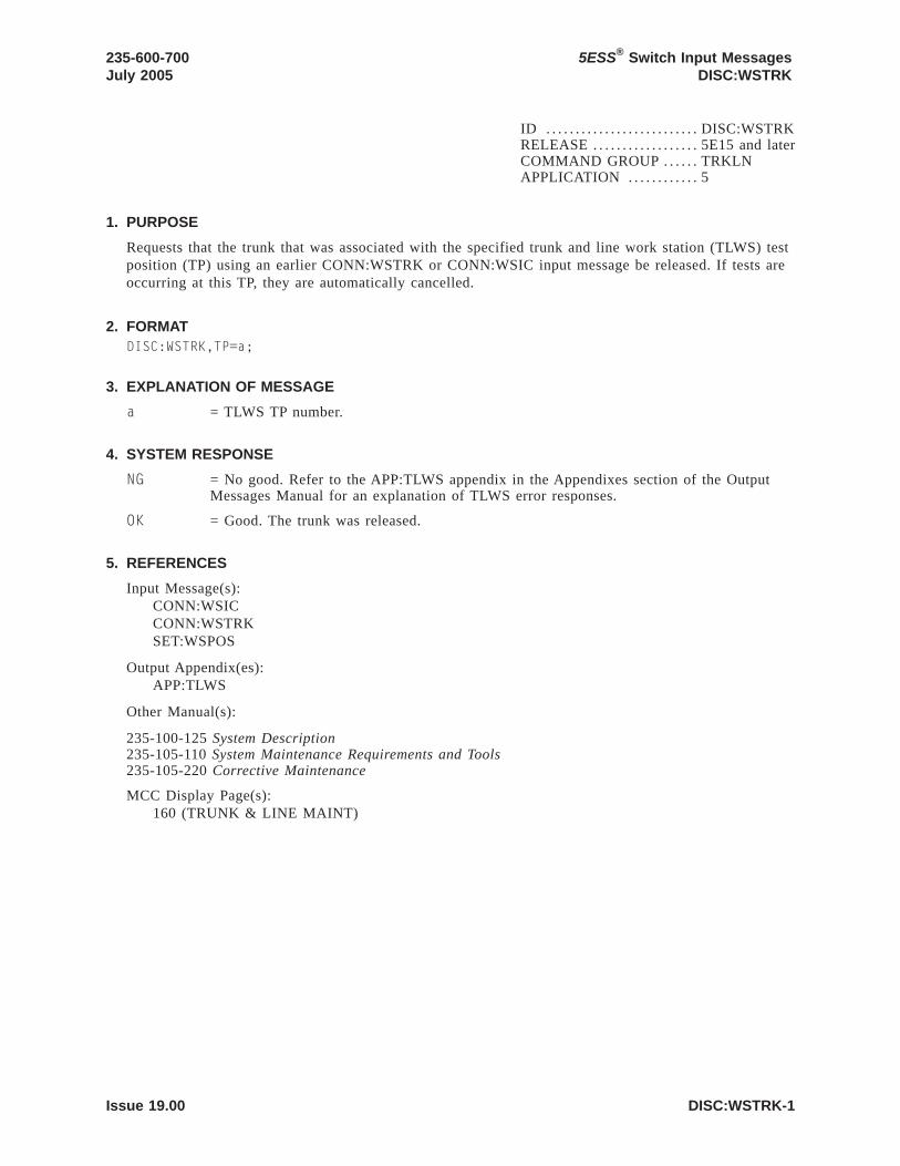
ID . . . . . . . . . . . . . . . . . . . . . . . . . . DISC:WSTRKRELEASE . . . . . . . . . . . . . . . . . . 5E15 and laterCOMMAND GROUP . . . . . . TRKLNAPPLICATION . . . . . . . . . . . . 5
1. PURPOSE
Requests that the trunk that was associated with the specified trunk and line work station (TLWS) testposition (TP) using an earlier CONN:WSTRK or CONN:WSIC input message be released. If tests areoccurring at this TP, they are automatically cancelled.
2. FORMATDISC:WSTRK,TP=a;
3. EXPLANATION OF MESSAGE
a = TLWS TP number.
4. SYSTEM RESPONSE
NG = No good. Refer to the APP:TLWS appendix in the Appendixes section of the OutputMessages Manual for an explanation of TLWS error responses.
OK = Good. The trunk was released.
5. REFERENCES
Input Message(s):CONN:WSICCONN:WSTRKSET:WSPOS
Output Appendix(es):APP:TLWS
Other Manual(s):
235-100-125 System Description235-105-110 System Maintenance Requirements and Tools235-105-220 Corrective Maintenance
MCC Display Page(s):160 (TRUNK & LINE MAINT)
235-600-700July 2005
5ESS® Switch Input MessagesDISC:WSTRK
Issue 19.00 DISC:WSTRK-1


ID . . . . . . . . . . . . . . . . . . . . . . . . . . DUMP:ACSRRELEASE . . . . . . . . . . . . . . . . . . 5E15 and laterCOMMAND GROUP . . . . . . RCVAPPLICATION . . . . . . . . . . . . 5
1. PURPOSE
Requests that automatic customer station rearrangement (ACSR) recent change log and error data filesbe printed.
2. FORMATDUMP:ACSR:DATA=a,FILE=b,DEVICE=c;
3. EXPLANATION OF MESSAGE
a = Data file type. Valid value(s):
LOG = ACSR recent change log file.ERR = ACSR recent change error data file.
b = Age of log or error data files in days. Valid value(s):
1 = Current day’s log or error data file.2 = Yesterday’s log or error data file.3 = Log and error data files from two days ago.ALL = All log or error data files.
c = Output device name. Valid value(s):
TERM = Output device is the input terminal.ROP = Output device is the receive-only printer (ROP).ALL = Output devices are the ROP and the input terminal.
4. SYSTEM RESPONSE
PF = Printout follows. Followed by the DUMP:ACSR output message.
5. REFERENCES
Output Message(s):DUMP:ACSR
235-600-700July 2005
5ESS® Switch Input MessagesDUMP:ACSR
Issue 19.00 DUMP:ACSR-1


ID . . . . . . . . . . . . . . . . . . . . . . . . . . DUMP:ADDRRELEASE . . . . . . . . . . . . . . . . . . 5E15 and laterCOMMAND GROUP . . . . . . SFTUTILAPPLICATION . . . . . . . . . . . . 5,3B
1. PURPOSE
Requests that the contents of a specified range of virtual addresses in the administrative module (AM)main memory be dumped as an action associated with a breakpoint.
The range is specified by two addresses or an address and a length. The length defaults to a value ofone. If only one address is given, indirect addressing may be specified. In this case, the first offsetlisted is added to the contents of the given address and the result is interpreted as a virtual address.The number of offsets specified defines the length of the chain of virtual addresses to be accessed inthis way before accessing the desired range of dump locations. For example, a single offset with valuezero uses the virtual address found in the location specified in the DUMP:ADDR input message forthe dump location.
2. FORMATDUMP:ADDR={a&&b|a}[,OFF=c][,{L=d|NL=e}][:WORD]!
3. EXPLANATION OF MESSAGE
WORD = Indicates that all addresses, offsets, and lengths are to be interpreted as words,including addresses derived in address chains. If this option is omitted, they are assumedto be byte values.
a = Virtual address or the lower limit of a range of virtual addresses of the dump indecimal, binary, octal, or hexadecimal notation. Assumed to be a byte address unless theWORD option is used.
b = Upper limit of a range of virtual addresses. Assumed to be a byte address unless theWORD option is used.
c = A single offset or list of up to five offsets. Omission of the keyword implies no indirectaddressing. Offsets are in bytes unless the WORD option is used.
d = The length of the dump, assumed to be in bytes unless the WORD option is used.Maximum 128 bytes or 32 words. Default is one, unless a range is explicitly specified.The actual range of addresses dumped will be rounded out to word address boundaries.
e = Indicator that the operation should use the locations beginning ’e’ lower than thecalculated address and ending at the address. The locations are used in ascending order.Usage and limitation are the same as for the L option.
4. SYSTEM RESPONSE
IP = In progress. The input message has been added to the WHEN action list.
RL = Retry later. The system is in an overload condition.
5. REFERENCES
Input Message(s):DUMP:PIDDUMP:PMEMDUMP:REGDUMP:UIDWHEN:PID
235-600-700July 2005
5ESS® Switch Input MessagesDUMP:ADDR
Issue 19.00 DUMP:ADDR-1

WHEN:UID
Output Message(s):DUMP:ADDR
5ESS® Switch Input MessagesDUMP:ADDR
235-600-700July 2005
DUMP:ADDR-2 Issue 19.00

ID . . . . . . . . . . . . . . . . . . . . . . . . . . DUMP:ATDTA-ARELEASE . . . . . . . . . . . . . . . . . . 5E15 - 5E17(1)COMMAND GROUP . . . . . . N/AAPPLICATION . . . . . . . . . . . . 5
1. PURPOSE
Dumps the entries in the automatic trunk test scheduler (ATTS) schedule database which relate to aspecified ATTS test schedule.
2. FORMATDUMP:ATDTA[,SCHED=a][,WEEK=b][,DAY=c][,TGID=d];
3. EXPLANATION OF MESSAGE
a = The number of the ATTS test schedule whose test session entries are to be output (1 -20).
b = The number of the ATTS schedule week for which test session entries are to beselected for dumping (1 - 8).
c = The number of the day in the week for which test session entries are to be selected fordumping (1 - 7, where 1 corresponds to Monday).
d = The number of the trunk group associated with test session entries which are to beselected for dumping (1 - maximum TGs per office).
• If neither variables ’b’, ’c’, nor ’d’ are specified, then all test session entries for thespecified ATTS test schedule are dumped.
• If variable ’d’ is specified, then only test session entries related to the specified trunkgroup are dumped, according to the setting of parameters ’b’ and ’c’.
• If variable ’b’ is specified and variable ’c’ is not, then only test session entries relatedto any day of the given schedule week are dumped.
• If variable ’c’ is specified and variable ’b’ is not, then only test session entries relatedto the given day of the schedule week which is currently in effect are dumped.
• If variables ’b’ and ’c’ are both specified, then only test session entries related to thegiven day of the given schedule week are dumped.
4. SYSTEM RESPONSE
PF = Printout follows. The request has been accepted. Followed by the DUMP:ATDTA outputmessage.
5. REFERENCES
Input Message(s):DUMP:ATLOGDUMP:ATPRMOP:ATTSST:ATTSSTP:ATTS
Output Message(s):DUMP:ATDTADUMP:ATLOG
235-600-700July 2005
5ESS® Switch Input MessagesDUMP:ATDTA
Issue 19.00 DUMP:ATDTA-A-1

DUMP:ATPRMOP:ATTSREPT:ATTSST:ATTSSTP:ATTS
Other Manual(s):Where ’x’ is the release-specific version of the specified manual.
235-100-125 System Description235-105-210 Routine Operations and Maintenance235-118-251 Recent Change Procedures235-118-25x Recent Change Reference
RC/V View(s):
14.9 ATTS TEST SESSION SCHEDULE DATA14.10 ATTS TEST SCHEDULE PARAMETER
5ESS® Switch Input MessagesDUMP:ATDTA
235-600-700July 2005
DUMP:ATDTA-A-2 Issue 19.00

ID . . . . . . . . . . . . . . . . . . . . . . . . . . DUMP:ATDTA-BRELEASE . . . . . . . . . . . . . . . . . . 5E18(1) and laterCOMMAND GROUP . . . . . . N/AAPPLICATION . . . . . . . . . . . . 5
1. PURPOSE
Dumps the entries in the automatic trunk test scheduler (ATTS) schedule database which relate to aspecified ATTS test schedule.
2. FORMATDUMP:ATDTA[,SCHED=a][,WEEK=b][,DAY=c][,TGID=d];
3. EXPLANATION OF MESSAGE
a = The number of the ATTS test schedule whose test session entries are to be output (1 -20).
b = The number of the ATTS schedule week for which test session entries are to beselected for dumping (1 - 8).
c = The number of the day in the week for which test session entries are to be selected fordumping (1 - 7, where 1 corresponds to Monday).
d = The number of the trunk group associated with test session entries which are to beselected for dumping (1 - maximum TGs per office).
• If neither variables ’b’, ’c’, nor ’d’ are specified, then all test session entries for thespecified ATTS test schedule are dumped.
• If variable ’d’ is specified, then only test session entries related to the specified trunkgroup are dumped, according to the setting of parameters ’b’ and ’c’.
• If variable ’b’ is specified and variable ’c’ is not, then only test session entries relatedto any day of the given schedule week are dumped.
• If variable ’c’ is specified and variable ’b’ is not, then only test session entries relatedto the given day of the schedule week which is currently in effect are dumped.
• If variables ’b’ and ’c’ are both specified, then only test session entries related to thegiven day of the given schedule week are dumped.
4. SYSTEM RESPONSE
PF = Printout follows. The request has been accepted. Followed by the DUMP:ATDTA outputmessage.
RL = Retry later. May also include:
- DATA NOT DEFINED = Indicate no ATTS TEST SESSION SCHEDULE DATA definedin form RATSDTA. Prior to define the data in RATSDTA, scheduleparameters must be predefined in form ATTS TEST SESSION SCHEDULEPARAMETERS (RATSPRM).
5. REFERENCES
Input Message(s):DUMP:ATLOGDUMP:ATPRMOP:ATTS
235-600-700July 2005
5ESS® Switch Input MessagesDUMP:ATDTA
Issue 19.00 DUMP:ATDTA-B-1

ST:ATTSSTP:ATTS
Output Message(s):DUMP:ATDTADUMP:ATLOGDUMP:ATPRMOP:ATTSREPT:ATTSST:ATTSSTP:ATTS
Other Manual(s):Where ’x’ is the release-specific version of the specified manual.
235-100-125 System Description235-105-210 Routine Operations and Maintenance235-118-251 Recent Change Procedures235-118-25x Recent Change Reference
RC/V View(s):
14.9 ATTS TEST SESSION SCHEDULE DATA14.10 ATTS TEST SCHEDULE PARAMETER
5ESS® Switch Input MessagesDUMP:ATDTA
235-600-700July 2005
DUMP:ATDTA-B-2 Issue 19.00

ID . . . . . . . . . . . . . . . . . . . . . . . . . . DUMP:ATLOGRELEASE . . . . . . . . . . . . . . . . . . 5E15 and laterCOMMAND GROUP . . . . . . N/AAPPLICATION . . . . . . . . . . . . 5
1. PURPOSE
Retrieves scheduled trunk test data from automatic trunk test scheduler (ATTS) log files. Searchingcan be limited to: trunk tests defined in a particular schedule, or across all schedules (variable ’a’);trunk tests executed on a particular schedule week, or during any schedule week (variable ’b’); trunktests executed on a particular schedule day, or during any schedule day (variable ’c’); trunk test datafor members of a particular trunk group or for members of all trunk groups (variable ’d’); and/orpassed, failed, aborted, non-passing, or all trunk test results (variable ’e’).
2. FORMATDUMP:ATLOG[,SCHED=a][,WEEK=b][,DAY=c][,TGID=d][,STAT=e];
3. EXPLANATION OF MESSAGE
a = Schedule number (1 - 20). If this parameter is defaulted, all schedules are searched fortest data conforming to the other parameters.
b = Schedule week number (1 - 8).
c = Schedule day number (1 - 7).
d = Trunk group identifier (1 - maximum TGs per office).
e = Status type. Valid value(s):
A = Print aborted trunk test results only.
F = Print failed trunk test results only. This is the default value.
FA = Print failed or aborted (that is, non-passing) trunk test results only.
FU = Print failed and/or unavailable trunk test results only.
P = Print passed trunk test results only.
PFA = Print all trunk test results.
NOTE: If STAT is not specified on the command line, the default is to print failed trunk testresults only. If there are no failed trunk test results, the following message will be seen"NO TEST RESULTS MATCH INPUT PARAMETERS".
4. SYSTEM RESPONSE
ATTS retrieves the requested information from the log files and outputs the formatted test result datain tabular form, if any logged test result data matches the input parameters.
NG = No good. Valid value(s):
- INSUFFICIENT RESOURCES
PF = Printout follows. The request has been accepted. Followed by the DUMP:ATLOGoutput message.
5. REFERENCES
Input Message(s):DUMP:ATDTA
235-600-700July 2005
5ESS® Switch Input MessagesDUMP:ATLOG
Issue 19.00 DUMP:ATLOG-1

DUMP:ATLOGDUMP:ATPRMOP:ATTSST:ATTSSTP:ATTS
Output Message(s):DUMP:ATDTADUMP:ATLOGDUMP:ATPRMOP:ATTSREPT:ATTSST:ATTSSTP:ATTS
Other Manual(s):
Where ’x’ is the release-specific version of the specified manual.
235-118-251 Recent Change Procedures
235-118-25x Recent Change Reference
235-105-210 Routine Operations and Maintenance
235-100-125 System Description
RC/V View(s):14.9 (ATTS TEST SESSION SCHEDULE DATA)14.10 (ATTS TEST SCHEDULE PARAMETER)
5ESS® Switch Input MessagesDUMP:ATLOG
235-600-700July 2005
DUMP:ATLOG-2 Issue 19.00

ID . . . . . . . . . . . . . . . . . . . . . . . . . . DUMP:ATPRMRELEASE . . . . . . . . . . . . . . . . . . 5E15 and laterCOMMAND GROUP . . . . . . N/AAPPLICATION . . . . . . . . . . . . 5
1. PURPOSE
Dumps the entries in the automatic trunk test scheduler (ATTS) parameters database which relate to aspecified ATTS test schedule.
2. FORMATDUMP:ATPRM,SCHED=a;
3. EXPLANATION OF MESSAGE
a = The number of the ATTS test schedule whose parameters are to be dumped (1 - 20).
4. SYSTEM RESPONSE
PF = Printout follows. The request has been accepted. Followed by the DUMP:ATPRMoutput message.
5. REFERENCES
Input Message(s):DUMP:ATDTADUMP:ATLOGDUMP:ATPRMOP:ATTSST:ATTSSTP:ATTS
Output Message(s):DUMP:ATDTADUMP:ATLOGDUMP:ATPRMOP:ATTSREPT:ATTSST:ATTSSTP:ATTS
Other Manual(s):
Where (x) is the release-specific version of the specified manual.
235-118-251 Recent Change Procedures235-118-25x Recent Change Reference235-105-210 Routine Operations and Maintenance235-100-125 System Description
RC/V View(s):14.9 (ATTS TEST SESSION SCHEDULE DATA)14.10 (ATTS TEST SCHEDULE PARAMETER)
235-600-700July 2005
5ESS® Switch Input MessagesDUMP:ATPRM
Issue 19.00 DUMP:ATPRM-1


ID . . . . . . . . . . . . . . . . . . . . . . . . . . DUMP:BKTAPE-ARELEASE . . . . . . . . . . . . . . . . . . 5E15 onlyCOMMAND GROUP . . . . . . N/AAPPLICATION . . . . . . . . . . . . 5,3B
1. PURPOSE
Displays the contents of the multi-volume digital audio tape (DAT) logical volume headers andoptionally provides an estimate of how full the tape is.
2. FORMATDUMP:BKTAPE:TD="a" [,TPSIZE=b];
3. EXPLANATION OF MESSAGE
a = Device filename of the DAT drive. Refer to the User Guidelines for definitions andexamples of tape device names.
b = Length in meters of the DAT mounted on the specified drive. The length is used toestimate how full the tape is. Valid lengths are 30 through 90 meters.
4. SYSTEM RESPONSE
PF = Printout follows. Followed by a DUMP:BKTAPE output message.
5. REFERENCES
Input Message(s):COPY:BKDISKCOPY:BKTAPE
Output Message(s):DUMP:BKTAPE
Output Message(s):DUMP:BKTAPE
235-600-700July 2005
5ESS® Switch Input MessagesDUMP:BKTAPE
Issue 19.00 DUMP:BKTAPE-A-1


ID . . . . . . . . . . . . . . . . . . . . . . . . . . DUMP:BKTAPE-BRELEASE . . . . . . . . . . . . . . . . . . 5E16(1) and laterCOMMAND GROUP . . . . . . N/AAPPLICATION . . . . . . . . . . . . 5,3B
1. PURPOSE
Displays the contents of the multi-volume digital audio tape (DAT) logical volume headers andoptionally provides an estimate of how full the tape is.
2. FORMATDUMP:BKTAPE:TD="a" [,TPSIZE=b];
3. EXPLANATION OF MESSAGE
a = Device filename of the DAT drive. Refer to the User Guidelines for definitions andexamples of tape device names.
b = Length in meters of the DAT mounted on the specified drive. The length is used toestimate how full the tape is. Valid lengths are 60, 90, 120, 125, 150, and 170 meters.
4. SYSTEM RESPONSE
PF = Printout follows. Followed by a DUMP:BKTAPE output message.
5. REFERENCES
Input Message(s):COPY:BKDISKCOPY:BKTAPE
Output Message(s):DUMP:BKTAPE
235-600-700July 2006
5ESS® Switch Input MessagesDUMP:BKTAPE
Issue 19.01 DUMP:BKTAPE-B-1


ID . . . . . . . . . . . . . . . . . . . . . . . . . . DUMP:CACHERELEASE . . . . . . . . . . . . . . . . . . 5E15 and laterCOMMAND GROUP . . . . . . SFTUTILAPPLICATION . . . . . . . . . . . . 5,3B
1. PURPOSE
Dumps the contents of the offline cache into administrative module (AM) processor main memory. Theportions of cache dumped are the ones which map to the kernel and interrupt stacks. The inputmessage will not be accepted if the other control unit (CU) is in the standby state.
The cache (1Kbytes) is placed at virtual address 0x80000 for the interrupt stack portion and at virtualaddress 0x6a0000 for the kernel stack. In the case of the kernel stack, the address dumped to will notcorrespond to the actual start of the kernel stack. This offset is necessary to preserve the portions ofthe kernel stack which are not resident in the cache but which do map to the address range used forthe cache kernel stack. Whether a particular stack entry is in cache or main memory is dependent uponwhether the hardware is present and enabled, and the state of the ISTK bit in the program status word(PSW) of the running process. The reconstruction of the kernel stack (both cache and main memory) isleft to the user.
2. FORMATDUMP:CACHE;
3. EXPLANATION OF MESSAGE
No variables.
4. SYSTEM RESPONSE
NG = No good. Could not access or reserve the unit control block (UCB) record of the mateCU, or the mate CU was not out of service.
PF = Printout follows. Followed by the DUMP:CACHE output message.
5. REFERENCES
Output Message(s):DUMP:CACHE
235-600-700July 2005
5ESS® Switch Input MessagesDUMP:CACHE
Issue 19.00 DUMP:CACHE-1


ID . . . . . . . . . . . . . . . . . . . . . . . . . . DUMP:F-ALLRELEASE . . . . . . . . . . . . . . . . . . 5E15 and laterCOMMAND GROUP . . . . . . FHADMAPPLICATION . . . . . . . . . . . . 5,3B
1. PURPOSE
Requests that the contents of an ASCII file be dumped.
2. FORMATDUMP:FILE,ALL,FN="a"[,OPL=b];
3. EXPLANATION OF MESSAGE
a = Pathname of the file.
Note: Dumps of directories and/or non-ASCII files may produce unpredictable output.
b = Number of segments output, specified in decimal. Default is 10 segments. Maximumnumber of segments is 999. Each segment has a maximum size of 1000 bytes or 20 lines.
4. SYSTEM RESPONSE
PF = Printout follows. Followed by the DUMP:F-ALL output message.
5. REFERENCES
Input Message(s):DUMP:F-PARTL
Output Message(s):DUMP:F-ALLDUMP:F-PARTL
Other Manual(s):
235-105-210 Routine Operations and Maintenance
MCC Display Page(s):(CRAFT FM 01)
235-600-700July 2005
5ESS® Switch Input MessagesDUMP:FILE,ALL
Issue 19.00 DUMP:F-ALL-1


ID . . . . . . . . . . . . . . . . . . . . . . . . . . DUMP:F-FORMATRELEASE . . . . . . . . . . . . . . . . . . 5E15 and laterCOMMAND GROUP . . . . . . FHADMAPPLICATION . . . . . . . . . . . . 5,3B
1. PURPOSE
Dumps the contents of a file in the specified format. If no format is given, the dump is printed inoctal.
2. FORMATDUMP:FILE,FORMAT, FN="a" [,b] [,OPL=c];
3. EXPLANATION OF MESSAGE
a = Pathname of the file. The pathname is a list of the names of each directory leading tothe file, and ends with the name of the specific file. Each name begins with a slash, andthe entire pathname is enclosed in quotation marks. For example, "usr/a1/ssw/test" meansthat /usr/a1/ssw/ represents the list of directory names and /test represents the file name.
b = Specifies the output format (default is octal). Valid value(s):
C = Interprets bytes in ASCII notation.D = Interprets words in decimal notation.O = Interprets words in octal notation.X = Interprets words in hexadecimal notation.
c = Number of segments output, specified in decimal. Refer to the APP:RANGES appendixin the Appendixes section of the Input Messages manual. Default is 10 segments. Eachsegment has a maximum size of 1000 bytes or 20 lines.
4. SYSTEM RESPONSE
PF = Printout follows. Followed by the DUMP:F-FORMAT output message.
5. REFERENCES
Input Message(s):DUMP:F-ALLDUMP:F-PARTL
Output Message(s):DUMP:F-ALLDUMP:F-FORMATDUMP:F-PARTL
Input Appendix(es):APP:RANGES
Other Manual(s):
235-105-210 Routine Operations and Maintenance
MCC Display Page(s):(CRAFT FM 01)
235-600-700July 2005
5ESS® Switch Input MessagesDUMP:FILE:FORMAT
Issue 19.00 DUMP:F-FORMAT-1


ID . . . . . . . . . . . . . . . . . . . . . . . . . . DUMP:F-PARTLRELEASE . . . . . . . . . . . . . . . . . . 5E15 and laterCOMMAND GROUP . . . . . . FHADMAPPLICATION . . . . . . . . . . . . 5,3B
1. PURPOSE
Prints one or more lines of an American standard code for information interchange (ASCII) file.
Note: Specifying a non-ASCII file may produce unpredictable output.
2. FORMATDUMP:FILE,PARTL,FN="a",LINE=b[&&c];
3. EXPLANATION OF MESSAGE
a = Pathname of the file.
b = Line number to be printed or first line of a range, specified in decimal. If the linenumber specified (limited to 1 through 131072) is larger than the number of lines in thefile, the last line of the file is assumed.
c = Last line number of a range (limited to 1 through 131072). If larger then the number oflines in the file, the last line of the file is assumed.
4. SYSTEM RESPONSE
PF = Printout follows. Followed by the DUMP:F-PARTL output message.
5. REFERENCES
Input Message(s):DUMP:F-ALL
Output Message(s):DUMP:F-ALLDUMP:F-FORMATDUMP:F-PARTL
Other Manual(s):
235-105-210 Routine Operations and Maintenance
MCC Display Page(s):(CRAFT FM 01)
235-600-700July 2005
5ESS® Switch Input MessagesDUMP:FILE,PARTL
Issue 19.00 DUMP:F-PARTL-1


ID . . . . . . . . . . . . . . . . . . . . . . . . . . DUMP:KERNRELEASE . . . . . . . . . . . . . . . . . . 5E15 and laterCOMMAND GROUP . . . . . . SFTUTILAPPLICATION . . . . . . . . . . . . 5,3B
1. PURPOSE
Requests that the contents of a specified range of virtual addresses in the administrative module (AM)kernel be dumped as an immediate action.
The range is specified by two addresses or an address and a length. The length defaults to a value of1. If only one address is given, indirect addressing may be specified. In this case, the first offset listedis added to the content of the given address and the result is interpreted as a virtual address. Thenumber of offsets specified defines the length of the chain of virtual addresses to be accessed in thisway before accessing the desired range of dump locations. For example, a single offset with value 0uses the virtual address found in the location specified in the DUMP:KERN message for the dumplocation.
2. FORMATDUMP:KERN={a&&b|a[,OFF=c][,{L=d|NL=e}]};
3. EXPLANATION OF MESSAGE
a = Virtual byte address of the dump or the lower limit of a range of virtual byte addresses,in decimal, octal, or hexadecimal.
b = Upper limit of a range of virtual byte addresses of the dump.
c = A single offset or list of up to 5 offsets. Omission of the keyword implies no indirectaddressing.
d = The length of the dump, assumed to be in bytes. The maximum is 128 bytes. Thedefault is 1, unless a range is explicitly specified. The actual range of addresses to bedumped will be rounded out to word address boundaries.
e = Indicator that the operation should use the locations beginning ’e’ lower than thecalculated address and ending at the address. The locations are used in ascending order.Usage and limitations are the same as for the ’d’ option.
4. SYSTEM RESPONSE
IP = In progress. The message has been added to the WHEN action list.
PF = Printout follows.
RL = Retry later. The system is in an overload condition.
5. REFERENCES
Input Message(s):DUMP:PIDDUMP:PMEMDUMP:REGDUMP:UIDWHEN:PIDWHEN:UID
Output Message(s):DUMP:ADDR
235-600-700July 2005
5ESS® Switch Input MessagesDUMP:KERN
Issue 19.00 DUMP:KERN-1

DUMP:KERNWHEN:PIDWHEN:UID
5ESS® Switch Input MessagesDUMP:KERN
235-600-700July 2005
DUMP:KERN-2 Issue 19.00

ID . . . . . . . . . . . . . . . . . . . . . . . . . . DUMP:MHD-BLOCKRELEASE . . . . . . . . . . . . . . . . . . 5E15 and laterCOMMAND GROUP . . . . . . FHADMAPPLICATION . . . . . . . . . . . . 5,3B
1. PURPOSE
Dumps the contents of a specified single disk block or a range of blocks, in hexadecimal. One diskblock contains 512 bytes.
The moving head disk (MHD) does not have to be in the active state for this request to work.
Warning: Do not input this request at the same time as another request for the same MHD,because errors due to resource limitations may occur.
2. FORMATDUMP:MHD=a:BLOCK=b[&&c][,DEST={ROP|"d"}];
3. EXPLANATION OF MESSAGE
DEST = Destination of the output. A maximum of five disk blocks can be directed to the ROPby a single input request. Default is the inputting teletypewriter (TTY).
a = Member number. Refer to the APP:RANGES appendix in the Appendixes section of theInput Messages manual.
b = Disk block offset from the start of the disk, specified in decimal. Refer to theAPP:RANGES appendix in the Appendixes section of the Input Messages manual. May bethe first block of a range of blocks. Block 0 is the first block of a disk.
c = Last block of a range of blocks. Refer to the APP:RANGES appendix in theAppendixes section of the Input Messages manual.
d = Pathname of a file to receive the data. There is no limit on the number of disk blocksthat can be directed to a file by a single input request.
4. SYSTEM RESPONSE
PF = Printout follows. Followed by the DUMP:MHD-BLOCK output message.
5. REFERENCES
Output Message(s):DUMP:MHD-BLOCK
Input Appendix(es):APP:RANGES
235-600-700July 2005
5ESS® Switch Input MessagesDUMP:MHD
**WARNING**INAPPROPRIATE USE OF THIS MESSAGEMAY INTERRUPT OR DEGRADE SERVICE.
READ PURPOSE CAREFULLY.
Issue 19.00 DUMP:MHD-BLOCK-1


ID . . . . . . . . . . . . . . . . . . . . . . . . . . DUMP:MHD-DEFECTRELEASE . . . . . . . . . . . . . . . . . . 5E15 and laterCOMMAND GROUP . . . . . . FHADMAPPLICATION . . . . . . . . . . . . 5,3B
1. PURPOSE
Warning: Do not input this request at the same time as another DUMP:MHD or VFY:MHDrequest because errors may occur.
Dumps defect management information for a moving head disk (MHD).
This message is used to read the defect table from an MHD. The tables specify the location of mediadefects. This information is used by the MHD’s controller to map around defective areas on the media.
- This message should ony be used for disk drives that support defect managementotherwise the input message will abort.
- The MHD does not have to be in the active state to execute this message.
If no options are specified, the combined (COMB) defect tables will be output.
2. FORMATDUMP:MHD=a:DEFECT[:FN="b"|{[,COMB][,MFGR]|,ALL}];
3. EXPLANATION OF MESSAGE
a = MHD member number. Refer to the APP:RANGES appendix in the Appendixes sectionof the Input Messages manual.
b = Full pathname that specifies the file to which the MFGR defect table will be written.
For a storage module drive (SMD) MHD, the file will contain the manufacturer’s defecttable data in a format that can be used in a LOAD:MHD-DEFECT input message.
For a small computer system interface (SCSI) MHD, the contents of the file is purelyinformational and cannot be used as input to the LOAD:MHD-DEFECT input message.
COMB = Requests the combined defect table.
For an SMD MHD, this table represents the defect list currently being used by theMHD’s controller to map around the defects. The COMB defect table can be updated byusing the INIT:MHD input message with the NEW option. The update copies the currentMFGR defect table to the COMB defect table.
For a SCSI MHD, this table represents the GROWN defect list and contains only thosedefects added by the user. This list, in conjunction with the PRIMARY defect list, is usedby the MHD’s controller to map around media defects.
MFGR = Requests the manufacturer’s defect table.
For an SMD MHD, this table represents the original defects and defects added by theuser. This table is used to update the COMB defect table.
For a SCSI MHD, this table represents the PRIMARY defect list and contains only theoriginal defects. This list in conjunction with the GROWN defect list, is used by theMHD’s controller to map around media defects.
ALL = Requests both COMB and MFGR defect tables.
235-600-700July 2005
5ESS® Switch Input MessagesDUMP:MHD
**WARNING**INAPPROPRIATE USE OF THIS MESSAGEMAY INTERRUPT OR DEGRADE SERVICE.
READ PURPOSE CAREFULLY.
Issue 19.00 DUMP:MHD-DEFECT-1

4. SYSTEM RESPONSE
PF = Printout follows. Followed by the DUMP:MHD-DEFECT output message.
5. REFERENCES
Input Message(s):INIT:MHDLOAD:MHDVFY:MHD
Output Message(s):DUMP:MHD-DEFECTLOAD:MHD-DEFECT
Input Appendix(es):APP:RANGES
MCC Display Page(s):(DISK FILE SYSTEM ACCESS)
5ESS® Switch Input MessagesDUMP:MHD
235-600-700July 2005
DUMP:MHD-DEFECT-2 Issue 19.00

ID . . . . . . . . . . . . . . . . . . . . . . . . . . DUMP:MHD-VTOCRELEASE . . . . . . . . . . . . . . . . . . 5E15 and laterCOMMAND GROUP . . . . . . FHADMAPPLICATION . . . . . . . . . . . . 5,3B
1. PURPOSE
Warning: Do not input this request at the same time as a VFY:MHD, DUMP:MHD-BLOCK,DUMP:MHD-DEFECT or another DUMP:MHD-VTOC request, because errors may occur.
Formats and prints the contents of a disk pack’s volume table of contents (VTOC). The output willonly appear on the receive-only printer (ROP). The moving head disk (MHD) does not have to be inthe active state for this input message to work.
2. FORMATDUMP:MHD=a:VTOC[,SORT={B|P}];
3. EXPLANATION OF MESSAGE
SORT = Specifies the sort algorithm to be used in formatting the output data. Valid value(s):
B = Sort by ascending disk block addresses (default).P = Sort by ascending logical partition numbers.
Note: Disk packs used in the UNIX1 RTR operating system must have a VTOC starting at blocknumber zero.
a = Member number. Refer to the APP:RANGES appendix in the Appendixes section of theInput Messages manual.
4. SYSTEM RESPONSE
PF = Printout follows. Followed by the DUMP:MHD-VTOC output message.
5. REFERENCES
Input Message(s):DUMP:MHD-BLOCKDUMP:MHD-DEFECTVFY:MHD
Output Message(s):DUMP:MHD-VTOC
Input Appendix(es):APP:RANGES
1. Registered trademark of X/Open Company, Ltd.
235-600-700July 2005
5ESS® Switch Input MessagesDUMP:MHD
**WARNING**INAPPROPRIATE USE OF THIS MESSAGEMAY INTERRUPT OR DEGRADE SERVICE.
READ PURPOSE CAREFULLY.
Issue 19.00 DUMP:MHD-VTOC-1


ID . . . . . . . . . . . . . . . . . . . . . . . . . . DUMP:NCRELEASE . . . . . . . . . . . . . . . . . . 5E15 and laterCOMMAND GROUP . . . . . . CMAPPLICATION . . . . . . . . . . . . 5
1. PURPOSE
Requests a dump of information related to the network clock model 2 (NC2) or model 3 (NC3).
2. FORMATDUMP:NC=a;
3. EXPLANATION OF MESSAGE
a = Side of the office network and timing complex (ONTC) that the NC is on. Refer to theAPP:RANGES appendix in the Appendixes section of the Input Messages manual.
4. SYSTEM RESPONSE
NG = No good. The request has been denied. The message syntax is valid, but the requestcould not be processed. Refer to the APP:CM-IM-REASON appendix in the Appendixessection of the Input Messages manual for a list of possible reasons for denying therequest.
PF = Printout follows.
RL = Retry later. The request cannot be executed now because the communication module(CM) deferred maintenance queue (DMQ) is full.
5. REFERENCES
Output Message(s):DUMP:NCDUMP:NC3
Input Appendix(es):APP:CM-IM-REASONAPP:RANGES
235-600-700July 2005
5ESS® Switch Input MessagesDUMP:NC
Issue 19.00 DUMP:NC-1


ID . . . . . . . . . . . . . . . . . . . . . . . . . . DUMP:PIDRELEASE . . . . . . . . . . . . . . . . . . 5E15 and laterCOMMAND GROUP . . . . . . SFTUTILAPPLICATION . . . . . . . . . . . . 5,3B
1. PURPOSE
Dumps the contents of the specified range of virtual addresses in administrative module (AM) mainmemory in the address space of the process with the specified process identifier. This message cannotbe used as an action associated with a breakpoint. The range is specified by two addresses or as oneaddress and a length. The length defaults to a value of 1.
If only one address is given, indirect addressing may be specified. In this case, the first offset listed isadded to the value of the given address and the result is interpreted as another address. The number ofoffsets specified defines the length of the chain of virtual addresses to be accessed in this way beforeaccessing the desired range of dump locations. For example, a single offset with value 0 uses thevirtual address found in the location specified in the DUMP:PID input message for the dump location.
2. FORMATDUMP:PID=a,ADDR={b&&c|b[,OFF=d][,{L=e|NL=f}]}[:WORD];
3. EXPLANATION OF MESSAGE
WORD = Indicates that all addresses, offsets, and lengths are to be interpreted in terms of wordsincluding addresses derived in address chains. If this option is omitted, they are assumedto be byte values.
a = Process ID of the target process.
b = Starting virtual address of the dump in decimal, octal, or hexadecimal notation.Assumed to be a byte address unless the WORD option is used.
c = Ending virtual address of the dump. Assumed to be a byte address unless the WORDoption is used.
d = A single offset or list of up to five offsets. Omission of the keyword implies no indirectaddressing. Offsets are in bytes unless the WORD option is used.
e = The length of the dump, assumed to be in bytes unless the WORD option is used.Default=1, unless a range is explicitly specified. The actual range of addresses to bedumped will be rounded out to word address boundaries.
f = Used to indicate that the operation should use the locations beginning ’e’ lower thanthe calculated address and ending at the address. The locations are used in ascendingorder. Usage and limitations are the same as for the L option.
4. SYSTEM RESPONSE
NG = No good. The PID is for a process for which dumps are not permitted.
PF = Printout follows. Followed by the DUMP:PID output message.
RL = Retry later. The system is in an overload condition or completing the previousOP:UMEM or OP:UMEM:MCH message.
5. REFERENCES
Input Message(s):DUMP:ADDRDUMP:PMEM
235-600-700July 2005
5ESS® Switch Input MessagesDUMP-PID
Issue 19.00 DUMP:PID-1

DUMP:REGDUMP:UIDOP:ST-PROC
Output Message(s):DUMP:PID
Input Appendix(es):APP:RANGES
5ESS® Switch Input MessagesDUMP-PID
235-600-700July 2005
DUMP:PID-2 Issue 19.00

ID . . . . . . . . . . . . . . . . . . . . . . . . . . DUMP:PMEMRELEASE . . . . . . . . . . . . . . . . . . 5E15 and laterCOMMAND GROUP . . . . . . SFTUTILAPPLICATION . . . . . . . . . . . . 5,3B
1. PURPOSE
Dumps the contents of a specified range of physical addresses in main memory.
The range is specified by two addresses or by one address and an optional byte length count. Thedefault length is 4 bytes.
The output will contain formatted fullwords. If the addresses specified did not describe a set offullwords, the addresses will be rounded out to fullword boundaries. For example, physical memoryaddresses X’4041-X’405D (in hexadecimal) would be treated as hexadecimal numbers X’4040-X’405F.
This message may be used either as an immediate input message or in the action list of a WHEN.
2. FORMATDUMP:PMEM={a&&b|a[,{L=c|NL=d}]}{!|;}
3. EXPLANATION OF MESSAGE
a = Starting (if L is used) or ending (if NL is used) physical address dump in decimal,octal, or hexadecimal notation. Value will be rounded down to a fullword address.
b = Ending physical address for dump in decimal, octal, or hexadecimal notation. Valuewill be rounded up to the next fullword boundary.
c = Indicator that the ending address should be calculated by adding the byte length ’c’ tothe starting address ’a’ and then rounding up to the next fullword boundary.
d = Byte length used to calculate the starting address. The byte length ’d’ is subtractedfrom the ending address ’a’ and then rounded down to a fullword boundary. The address’a’ is rounded up to the next fullword boundary and is used as the ending address.
4. SYSTEM RESPONSE
IP = In progress. The message has been added to the WHEN action list.
PF = Printout follows. Followed by the DUMP:PMEM output message.
RL = Retry later. The system is in an overload condition.
5. REFERENCES
Input Message(s):DUMP:PIDDUMP:UIDWHEN:PIDWHEN:UID
Output Message(s):DUMP:PMEM
235-600-700July 2005
5ESS® Switch Input MessagesDUMP:PMEM
Issue 19.00 DUMP:PMEM-1


ID . . . . . . . . . . . . . . . . . . . . . . . . . . DUMP:REGRELEASE . . . . . . . . . . . . . . . . . . 5E15 and laterCOMMAND GROUP . . . . . . SFTUTILAPPLICATION . . . . . . . . . . . . 5,3B
1. PURPOSE
Dumps the contents of one or more registers, either as an immediate action, or as an action associatedwith a breakpoint.
This message can also be used to dump an address range in main memory (by specifying a singleregister and offsets), but only if the message is part of an action list for a WHEN message.
If offsets are specified, the first offset is added to the contents of the specified register and the resultis interpreted as a virtual address. The number of offsets specified defines the length of the chain ofvirtual addresses to be accessed in this way before accessing the desired range of dump locations. Forexample, a single offset with value uses the virtual address found in the register for the memory dumplocation.
Note: Offsets can only be used if the DUMP:REG message is used as an action associated witha breakpoint, since that defines a process address space for memory addressing.
2. FORMATDUMP:REG=a[,OFF=b][,{L|NL}=c][:WORD]{!|;}
3. EXPLANATION OF MESSAGE
a = Single register name or a list of registers to be dumped. Valid value(s):
AP = Argument pointer AP.ATBBGR = Register used by the ATB miss routine to temporarily store the
bi-directional gating register (BGR).ATBPSW = Register used by the ATB miss routine to temporarily store the program
status word (PSW) register.ATBQ = Register used by the ATB miss routine to temporarily store the ’q’
register.ATBSAR = Register used by the address translation buffer (ATB) miss routine to
temporarily store the store address register (SAR) contents.ATBSCR = Register used by the ATB miss routine to temporarily store the store
control register (SCR) contents.ATBSDR = Register used by the ATB miss routine to temporarily store the store data
register (SDR) content.BGR = Bi-directional gating register.CAR = Channel address register.CDR = Channel data register.ERC = Error register (ER) clear.FP = Frame pointer FP.HG = Reserved register HG.HSR = Hardware status register.HSRBGC = Bi-directional gating control bits of the hardware status register (HSR).IM = Interrupt mask register IM.ISC = IS (interrupt source) register clear.ISS = Interrupt source (IS) register set.PA = Program address register.PPR = Pulse point register.PSW = Program status word.R0 = General register R0.R1 = General register R1.
235-600-700July 2005
5ESS® Switch Input MessagesDUMP:REG
Issue 19.00 DUMP:REG-1

R2 = General register R2.R3 = General register R3.R4 = General register R4.R5 = General register R5.R6 = General register R6.R7 = General register R7.R8 = General register R8.R9 = Argument pointer AP.R10 = Frame pointer FP.R11 = Stack pointer SP.RNULL = Null register.RTC = Real time clock.SBR0 = Segment base register SBR0.SBR1 = Segment base register SBR1.SBR2 = Segment base register SBR2.SBR3 = Segment base register SBR3.SBR4 = Segment base register SBR4.SBR5 = Segment base register SBR5.SBR6 = Segment base register SBR6.SBR7 = Segment base register SBR7.SCRATCH0 = JE group temp subgroup scratch register SCRATCH0.SCRATCH1 = JE group temp subgroup scratch register SCRATCH1.SDR = Store data register.SP = Stack pointer SP.SSRC = System status register (SSR) clear.SSRS = SSR set.SYSBASE = Beginning address of UNIX1 RTR Operating System tab.T0 = JE group temp subgroup scratch register T0.T1 = JE group temp subgroup scratch register T1.T2 = JE group temp subgroup scratch register T2.T3 = JE group temp subgroup scratch register T3.T4 = JE group temp subgroup scratch register T4.T5 = JE group temp subgroup scratch register T5.T6 = JE group temp subgroup scratch register T6.T7 = JE group temp subgroup scratch register T7.TIMERS = Timing circuit.TOPIS = Interrupt stack pointer.UINT0 = Error microinterrupt hander register UINT0.UINT1 = Error microinterrupt hander register UINT1.UINT2 = Error microinterrupt hander register UINT2.UINT3 = Error microinterrupt hander register UINT3.UINTER = Shadow error register (uint_er) loaded during an error microinterrupt.
b = Offset. Omission of the keyword implies no indirect addressing. Offsets are onlyallowed if one register is specified. Offsets are in bytes unless the WORD option is used.
c = The length of the dump, in bytes unless the WORD option is used. The maximum is128 bytes or 32 words for memory dumps and 4 bytes for register dumps. The default is1 unless a range is explicitly specified. The actual range of addresses to be dumped willbe rounded out to word address boundaries.
c = Indicator that the operation should use the locations beginning ’c’ lower than thecalculated address and ending at the address. The locations are used in ascending order.Usage and limitations are the same as for the L option.
1. Registered trademark of X/Open Company, Ltd.
5ESS® Switch Input MessagesDUMP:REG
235-600-700July 2005
DUMP:REG-2 Issue 19.00

WORD = Indicates that all addresses, offsets, and lengths are to be interpreted in terms of words,including addresses derived in address chains. If this option is omitted they are assumedto be byte values.
4. SYSTEM RESPONSE
IP = In progress. The message has been added to the WHEN action list.
NG = No good. May also include:- BAD REG NAME
PF = Printout follows. Followed by the DUMP:REG output message.
RL = Retry later. The system is in an overload condition or completing a previousOP:UMEM message.
5. REFERENCES
Input Message(s):DUMP:ADDRDUMP:PIDDUMP:PMEMDUMP:UIDOP:UMEMWHEN:PIDWHEN:UID
Output Message(s):DUMP:REG
235-600-700July 2005
5ESS® Switch Input MessagesDUMP:REG
Issue 19.00 DUMP:REG-3


ID . . . . . . . . . . . . . . . . . . . . . . . . . . DUMP:RUTILRELEASE . . . . . . . . . . . . . . . . . . 5E15 and laterCOMMAND GROUP . . . . . . SFTUTILAPPLICATION . . . . . . . . . . . . 5
1. PURPOSE
Requests a dump of the memory contents of the specified address at the given common networkinterface (CNI) ring node. Currently a maximum length of 468 bytes is allowed for a single dumpoperation. All addresses are to be provided in hexadecimal. All lengths are to be specified in decimal.
Format 1 dumps the contents of memory at the address range given at the specified CNI ring node.
Warning: Incorrect use of this input message may interrupt operation of a node on the CNI ringor the whole CNI ring.
Format 2 dumps the contents of memory from the given address for the specified length.
2. FORMAT[1] DUMP:RUTIL=a-b,AP:ADDR=c-d;[2] DUMP:RUTIL=a-b,AP:ADDR=c,{L=e|NL=f}[:WORD];
3. EXPLANATION OF MESSAGE
ADDR = Address.
AP = Attached processor.
WORD = If specified, ’e’ and ’f’ are the number of four-byte words to dump, otherwise they arethe number of bytes to dump.
a = Group number. Refer to the APP:RANGES appendix in the Appendixes section of theInput Messages manual.
b = Member number. Refer to the APP:RANGES appendix in the Appendixes section of theInput Messages manual.
c = Start address of the dump in hexadecimal.
d = End address of the dump in hexadecimal.
e = Length of the dump in decimal where ’c’ is the beginning of the address dump.
f = Length of the dump in decimal where ’c’ is the end address of the dump; the startaddress is calculated by using the end address minus the total number of bytes to dump.
4. SYSTEM RESPONSE
PF = Printout follows. Followed by the DUMP:RUTIL output message.
5. REFERENCES
Input Message(s):ALW:RUTILALW:RUTILFLAGCLR:RUTILCLR:RUTILFLAGINH:RUTILINH:RUTILFLAGLOAD:RUTIL
235-600-700July 2005
5ESS® Switch Input MessagesDUMP:RUTIL
**WARNING**INAPPROPRIATE USE OF THIS MESSAGEMAY INTERRUPT OR DEGRADE SERVICE.
READ PURPOSE CAREFULLY.
Issue 19.00 DUMP:RUTIL-1

OP:RUTILOP:RUTILFLAGWHEN:RUTIL
Output Message(s):ALW:RUTILALW:RUTILFLAGCLR:RUTILCLR:RUTILFLAGDUMP:RUTILINH:RUTILINH:RUTILFLAGLOAD:RUTILOP:RUTILOP:RUTILFLAGREPT:RUTILWHEN:RUTIL
Input Appendix(es):APP:RANGES
Other Manual(s):
235-105-110 System Maintenance Requirements and Tools
5ESS® Switch Input MessagesDUMP:RUTIL
235-600-700July 2005
DUMP:RUTIL-2 Issue 19.00

ID . . . . . . . . . . . . . . . . . . . . . . . . . . DUMP:SMEASRELEASE . . . . . . . . . . . . . . . . . . 5E15 and laterCOMMAND GROUP . . . . . . CCSAPPLICATION . . . . . . . . . . . . 5
1. PURPOSE
Requests a dump of the common channel interoffice signaling (CCIS) signaling measurements(SMEAS) from history files.
2. FORMATDUMP:SMEAS=a[-a]:HIST=b:{SLK=c-d[&&e-f]|NODE=c-d[&&e-f]|CHN=g[&&-h]|LS=i[&&j]|CLUSTER=k[&&l]}[:DEST=m];
3. EXPLANATION OF MESSAGE
a = Measurement identification. Refer to the References section of this message.
b = History file name (as it appears in /no5text/cni/meas). Valid value(s):
C30M = Current 30-minute data file.CDAY = Current day data file.CHRM = Current hour data file.L15M = Last 15-minute data file.L30M = Last 30-minute data file.LDAY = Last day data file.LHRM = Last hour data file.LPM = Last period measurement structure.
c = Group number or lower limit of a range of group numbers of signaling links (SLKs) ornodes.
d = Member number or a lower limit of a range of member numbers of SLKs or nodes.
e = Upper limit of a range of group numbers.
f = Upper limit of a range of member numbers.
g = Channel number (CHN) or lower limit of a range of channel numbers.
h = Upper limit of a range of channel numbers.
i = Link set (LS) or lower limit of a range of link set numbers.
j = Upper limit of a range of link set numbers.
k = Cluster or lower limit of a range of clusters.
l = Upper limit of a range of clusters.
m = Destination class. The ’destination number to output device’ cross-reference can befound by using the OP:OUTCLS input message.
4. SYSTEM RESPONSE
PF = Printout follows. Followed by the DUMP:SMEAS output message.
5. REFERENCES
Input Message(s):OP:OUTCLS
235-600-700July 2005
5ESS® Switch Input MessagesDUMP:SMEAS
Issue 19.00 DUMP:SMEAS-1

Output Message(s):DUMP:SMEAS
Other Manual(s):
Where (x) is the release-specific version of the specified manual.
235-118-21x Recent Change Procedures - Menu Mode235-190-120 Common Channel Signaling Service Features
5ESS® Switch Input MessagesDUMP:SMEAS
235-600-700July 2005
DUMP:SMEAS-2 Issue 19.00

ID . . . . . . . . . . . . . . . . . . . . . . . . . . DUMP:SMMAPRELEASE . . . . . . . . . . . . . . . . . . 5E15 and laterCOMMAND GROUP . . . . . . SMAPPLICATION . . . . . . . . . . . . 5
1. PURPOSE
Requests that the variable sections of switching module (SM) memory be dumped. The start and endaddresses of ODD ranges, real time billing memory, standalone billing memory, and any peripheralimage which is loaded in the SM, are given in the output.
2. FORMATDUMP:SMMAP,SM=a;
3. EXPLANATION OF MESSAGE
a = SM number.
4. SYSTEM RESPONSE
NG = No good. Request not initiated due to bad syntax or invalid SM specified.
PF = Printout follows. Followed by the DUMP:SMMAP output message.
5. REFERENCES
Output Message(s):DUMP:SMMAP
235-600-700July 2005
5ESS® Switch Input MessagesDUMP:SMMAP
Issue 19.00 DUMP:SMMAP-1


ID . . . . . . . . . . . . . . . . . . . . . . . . . . DUMP:TMS-ARELEASE . . . . . . . . . . . . . . . . . . 5E15 - 5E16(1)COMMAND GROUP . . . . . . CMAPPLICATION . . . . . . . . . . . . 5
1. PURPOSE
Requests a dump of the time multiplexed switch (TMS) error source registers (ESRs).
2. FORMATDUMP:TMS=a;
3. EXPLANATION OF MESSAGE
a = Side of the office network and timing complex (ONTC) that the TMS is on.
4. SYSTEM RESPONSE
NG = No good. The request has been denied. The message syntax is valid, but the requestcould not be processed. Refer to the APP:CM-IM-REASON appendix in the Appendixessection of the Input Messages manual for a list of possible reasons for denying therequest.
PF = Printout follows.
RL = Retry later. The request cannot be executed now because the communication module(CM) deferred maintenance queue (DMQ) is full.
5. REFERENCES
Output Message(s):DUMP:TMS
Input Appendix(es):APP:CM-IM-REASON
235-600-700July 2005
5ESS® Switch Input MessagesDUMP:TMS
Issue 19.00 DUMP:TMS-A-1


ID . . . . . . . . . . . . . . . . . . . . . . . . . . DUMP:TMS-BRELEASE . . . . . . . . . . . . . . . . . . 5E16(2) and laterCOMMAND GROUP . . . . . . CMAPPLICATION . . . . . . . . . . . . 5
1. PURPOSE
Requests a dump of the time multiplexed switch (TMS) error source registers (ESRs) and relatedinformation.
2. FORMATDUMP:TMS=a[,TMSFP=b];
3. EXPLANATION OF MESSAGE
a = Side of the office network and timing complex (ONTC) that the TMS is on.
b = The TMS fabric pair (TMSFP) number for which information should be dumped. Thisfield is only valid for CM3 offices, and will default to 0 if not specified. In a CM3 officewith multiple TMSFPs, a separate DUMP:TMS command must be entered for eachTMSFP in order to obtain data for the entire TMS.
4. SYSTEM RESPONSE
NG = No good. The request has been denied. The message syntax is valid, but the requestcould not be processed. Refer to the APP:CM-IM-REASON appendix in the Appendixessection of the Input Messages manual for a list of possible reasons for denying therequest.
PF = Printout follows.
RL = Retry later. The request cannot be executed now because the communication module(CM) deferred maintenance queue (DMQ) is full.
5. REFERENCES
Output Message(s):DUMP:TMS
Input Appendix(es):APP:CM-IM-REASON
235-600-700July 2005
5ESS® Switch Input MessagesDUMP:TMS
Issue 19.00 DUMP:TMS-B-1


ID . . . . . . . . . . . . . . . . . . . . . . . . . . DUMP:UIDRELEASE . . . . . . . . . . . . . . . . . . 5E15 and laterCOMMAND GROUP . . . . . . SFTUTILAPPLICATION . . . . . . . . . . . . 5,3B
1. PURPOSE
Dumps the contents of a specified range of virtual addresses in administrative module (AM) mainmemory in the address space of the process with the specified utility identifier. This message cannotbe used as an action associated with a breakpoint.
The range is specified by two addresses or by one address and a length. The length defaults to a valueof 1.
If only one address is given, indirect addressing may be specified. In this case, the first offset is addedto the value of the given address and the result is interpreted as a virtual address. The number ofoffsets specified defines the length of the chain of virtual addresses to be accessed in this way beforeaccessing the desired range of dump locations. For example, a single offset with value 0 uses thevirtual address found in the location specified in the DUMP:UID message for the dump location.
2. FORMATDUMP:UID=a,ADDR={b&&c|b[,OFF=d][,{L=e|NL=f}]}[:WORD];
3. EXPLANATION OF MESSAGE
WORD = Indicates that all addresses, offsets, and lengths are to be interpreted in terms of wordsincluding addresses derived in address chains. If this option is omitted they are assumedto be byte values.
a = Utility ID number of the target process.
b = Starting virtual address of the dump in decimal, binary, octal, or hexadecimal notation.Assumed to be a byte address unless the WORD option is used.
c = Ending virtual address of dump. Assumed to be a byte address unless the WORD optionis used.
d = Offset. Omission of the keyword implies no indirect addressing. Offsets are in bytesunless the WORD option is used.
e = The length of the dump, in bytes unless the WORD option is used. The maximum is128 bytes or 32 words. The default is 1, unless a range is explicitly specified. The actualrange of addresses to be dumped will be rounded out to word address boundaries.
f = Indicator that the operation should use the locations beginning ’f’ lower than thecalculated address and ending at the address. The locations are used in ascending order.Usage and limitations are the same as for the ’e’ option.
4. SYSTEM RESPONSE
NG = No good. The UID is for a process for which dumps are not permitted.
PF = Printout follows. Followed by the DUMP:UID output message.
RL = Retry later. The system is in an overload condition or completing a previousOP:UMEM message.
?A = Action field or command code contains an error. It may mean that the command codewas incorrectly typed or that a field delimiter was omitted. May also include:
INVALID KEYWORD = Message not allowed in a WHEN action list.
235-600-700July 2005
5ESS® Switch Input MessagesDUMP:UID
Issue 19.00 DUMP:UID-1

?I = General syntax error. May also include:
EXTRA KEYWORD (UID) = UID is not valid in a WHEN action list.INCONSISTENT DATA (ADDR) = Address range must be in ascending order.INPUT ERROR (OFF COUNT) = Too many offsets listed.RANGE ERROR (L or NL) = Length specified is too long or zero.RANGE ERROR (UID) = Utility ID is out of range.
5. REFERENCES
Input Message(s):DUMP:ADDRDUMP:PIDDUMP:PMEMDUMP:REGOP:UMEM
Output Message(s):DUMP:UID
5ESS® Switch Input MessagesDUMP:UID
235-600-700July 2005
DUMP:UID-2 Issue 19.00

ID . . . . . . . . . . . . . . . . . . . . . . . . . . DUMP:UT-CMP-ARELEASE . . . . . . . . . . . . . . . . . . 5E15 onlyCOMMAND GROUP . . . . . . SFTUTILAPPLICATION . . . . . . . . . . . . 5
1. PURPOSE
Requests that the contents of one or more sequential memory locations in the specifiedcommunications module processor (CMP) be dumped.
This message may be used together with any of the other CMP generic utility input messages (see theinput message listed in the Reference section).
If this message is used together with other generic utility messages, the END:UT-CMP input messagemay be used to signal the end of the series of messages.
Format 2 requests that a function trace be performed on the specified CMP. This input message canonly be used within a (non-timed) WHEN clause.
Warning: The user is responsible for any effects on system operation that result from the use ofthis input message. Know the effects of the message before using it.
2. FORMAT[1] DUMP:UT:CMP=a,{MATE|PRIM}[,DIS][,EA][,L=b],. . .
. . .{ADDR=c|REG=d|REGS|UVAR=e|GVAR="f"|SYMIDX=g}. . .
. . .[,INDIR=h][,OFF=i[-i][-i]]{!|;}________________________________________________________
[2] DUMP:UT:CMP=a,{MATE|PRIM},FTRACE{!|;}________________________________________________________
3. EXPLANATION OF MESSAGE
DIS = Dump the data in a disassembled format.
EA = Dump the effective address of the specified field instead of the contents.
MATE = Dump the contents of the standby CMP’s memory starting at the final calculatedaddress.
PRIM = Dump the contents of the active CMP’s memory starting at the final calculated address.
REGS = Dump data from all registers. If the data is dumped outside a WHEN clause, a dummyset of registers is used.
a = CMP number.
b = Length in bytes of the dump (1-8064). The full range is only available outside a WHENbreakpoint. Inside a WHEN breakpoint, the limit for output buffer is 2000, although UTwill dump around 1500 bytes storing header information in the remaining bytes. Defaultis 4 bytes for UVAR and REG unless REG is the status register which defaults to 2 bytes,1 byte for ADDR, GVAR and SYMIDX.
c = Absolute address of location to start the dump or the starting point for indirectaddressing.
d = Name of a specific register whose data is to be dumped.
If switch CM complex is a model 3, valid value(s):
CR = Condition register.CTR = Count register.EIMR = External interrupt mask register.GPR0 = General purpose register.
235-600-700July 2005
5ESS® Switch Input MessagesDUMP:UT
**WARNING**INAPPROPRIATE USE OF THIS MESSAGEMAY INTERRUPT OR DEGRADE SERVICE.
READ PURPOSE CAREFULLY.
Issue 19.00 DUMP:UT-CMP-A-1

GPR2-GPR31 = General purpose registers.LR = Link register.MSR = Machine state register.PC = Program counter. (from module processor).SMIMR = System management interrupt mask register (from module processor).SP (also known as GPR1) = General purpose register.XER = Integer exception.
If switch CM complex is model 2 or earlier, valid value(s):
A0-A5 = Address registers.A6 = The frame pointer FP.A7 = The stack pointer SP.D0-D7 = Data registers.PC = Program counter.SR = Status register.
If the data is dumped outside of a WHEN clause, a dummy set of registers is used.
e = Number of the utility variable UVAR (0-14) whose data is to be dumped.
f = Symbolic name of the global variable or function to be used to determine a startingaddress. The name is entered as a string of up to 15 characters, enclosed in doublequotation marks. If the symbol name is greater than 15 characters, the symbol indexnumber ’g’ must be used to enter this input message using symbolic access. The globalvariable’s symbol index number can be determined by using the DUMP:UT-SYMID inputmessage.
g = Symbol index number of this global variable. The symbol index can be determined forthis processor by using the DUMP:UT-SYMID input message.
h = The number of levels of indirection to be calculated by generic utilities (0-3,default=0).
i = The offsets, in bytes, at each level of indirection (0-65535, default=0). However, offsetsgreater than 32767 will be treated as negative offsets. One offset can be specified pereach level of indirection. Maximum number of offsets is 3.
4. SYSTEM RESPONSE
Refer to the APP:UT-IM-REASON appendix in the Appendixes section of the Input Messages manual.
5. REFERENCES
Input Message(s):ALW:UT-CMPCLR:UT-CMPCOPY:UT-CMPDUMP:UT-SYMIDELSE:UT-CMPEND:UT-CMPEND:UT-SMEXC:UT-CMPIF:UT-CMPIF:UT-CMP-ENDIFINH:UT-CMPLOAD:UT-CMPOP:UT-CMPWHEN:UT-CMP
5ESS® Switch Input MessagesDUMP:UT
235-600-700July 2005
DUMP:UT-CMP-A-2 Issue 19.00

Output Message(s):DUMP:UT-CMPREPT:STACK-TRACE
Input Appendix(es):APP:UT-IM-REASON
Other Manual(s):
235-105-110 System Maintenance Requirements and Tools
235-600-700July 2005
5ESS® Switch Input MessagesDUMP:UT
Issue 19.00 DUMP:UT-CMP-A-3


ID . . . . . . . . . . . . . . . . . . . . . . . . . . DUMP:UT-CMP-BRELEASE . . . . . . . . . . . . . . . . . . 5E16(1) and laterCOMMAND GROUP . . . . . . SFTUTILAPPLICATION . . . . . . . . . . . . 5
1. PURPOSE
Requests that the contents of one or more sequential memory locations in the specifiedcommunications module processor (CMP) be dumped.
This message may be used together with any of the other CMP generic utility input messages (see theinput message listed in the Reference section).
If this message is used together with other generic utility messages, the END:UT-CMP input messagemay be used to signal the end of the series of messages.
Format 2 requests that a function trace be performed on the specified CMP. This input message canonly be used within a (non-timed) WHEN clause.
Warning: The user is responsible for any effects on system operation that result from the use ofthis input message. Know the effects of the message before using it.
2. FORMAT[1] DUMP:UT:CMP=a,{MATE|PRIM}[,DIS][,EA][,L=b],. . .
. . .{ADDR=c|REG=d|REGS|UVAR=e|GVAR="f"|SYMIDX=g}[,INDIR=h]. . .
. . .[,OFF=i[-i][-i]]{!|;}________________________________________________________
[2] DUMP:UT:CMP=a,{MATE|PRIM},FTRACE{!|;}________________________________________________________
3. EXPLANATION OF MESSAGE
DIS = Dump the data in a disassembled format.
EA = Dump the effective address of the specified field instead of the contents.
MATE = Dump the contents of the standby CMP’s memory starting at the final calculatedaddress.
PRIM = Dump the contents of the active CMP’s memory starting at the final calculated address.
REGS = Dump data from all registers. If the data is dumped outside a WHEN clause, a dummyset of registers is used.
a = CMP number.
b = Length in bytes of the dump (1-8064). The full range is only available outside a WHENbreakpoint. Inside a WHEN breakpoint, the limit for output buffer is 2000, although UTwill dump around 1500 bytes storing header information in the remaining bytes. Defaultis 4 bytes for UVAR and REG unless REG is the status register which defaults to 2 bytes,1 byte for ADDR, GVAR and SYMIDX.
c = Absolute address of location to start the dump or the starting point for indirectaddressing.
d = Name of a specific register whose data is to be dumped.
If switch CM complex is a model 3, valid value(s):
CR = Condition register.CTR = Count register.EIMR = External interrupt mask register (from module processor).GPR0 = General purpose register.
235-600-700July 2005
5ESS® Switch Input MessagesDUMP:UT
**WARNING**INAPPROPRIATE USE OF THIS MESSAGEMAY INTERRUPT OR DEGRADE SERVICE.
READ PURPOSE CAREFULLY.
Issue 19.00 DUMP:UT-CMP-B-1

GPR2-GPR31 = General purpose registers.LR = Link register.MSR = Machine state register.PC = Program counter.SMIMR = System management interrupt mask register (from module processor).SP (also known as GPR1) = General purpose register.XER = Integer exception.
If switch CM complex is model 2 or earlier, valid value(s):
A0-A5 = Address registers.A6 = The frame pointer (FP).A7 = Stack pointer (SP).D0-D7 = Data registers.PC = Program counter.SR = Status register.
If the data is dumped outside of a WHEN clause, a dummy set of registers is used.
e = Number of the utility variable UVAR (0-14) whose data is to be dumped.
f = Symbolic name of the global variable or function to be used to determine a startingaddress. The name is entered as a string of up to 15 characters, enclosed in doublequotation marks. If the symbol name is greater than 15 characters, the symbol indexnumber ’g’ must be used to enter this input message using symbolic access. The globalvariable’s symbol index number can be determined by using the DUMP:UT-SYMID inputmessage.
g = Symbol index number of this global variable. The symbol index can be determined forthis processor by using the DUMP:UT-SYMID input message.
h = The number of levels of indirection to be calculated by generic utilities (0-3,default=0).
i = The offsets, in bytes, at each level of indirection (0-65535, default=0). However, offsetsgreater than 32767 will be treated as negative offsets. One offset can be specified pereach level of indirection. Maximum number of offsets is 3.
4. SYSTEM RESPONSE
Refer to the APP:UT-IM-REASON appendix in the Appendixes section of the Input Messages manual.
5. REFERENCES
Input Message(s):ALW:UT-CMPCLR:UT-CMPCOPY:UT-CMPDUMP:UT-SYMIDELSE:UT-CMPEND:UT-CMPEND:UT-SMEXC:UT-CMPIF:UT-CMPIF:UT-CMP-ENDIFINH:UT-CMPLOAD:UT-CMPOP:UT-CMPWHEN:UT-CMP
5ESS® Switch Input MessagesDUMP:UT
235-600-700July 2005
DUMP:UT-CMP-B-2 Issue 19.00

Output Message(s):DUMP:UT-CMPREPT:STACK-TRACE
Input Appendix(es):APP:UT-IM-REASON
Other Manual(s):
235-105-110 System Maintenance Requirements and Tools
235-600-700July 2005
5ESS® Switch Input MessagesDUMP:UT
Issue 19.00 DUMP:UT-CMP-B-3


ID . . . . . . . . . . . . . . . . . . . . . . . . . . DUMP:UT-CMPMSGRELEASE . . . . . . . . . . . . . . . . . . 5E15 and laterCOMMAND GROUP . . . . . . SFTUTILAPPLICATION . . . . . . . . . . . . 5
1. PURPOSE
Requests that the contents of one or more sequential memory locations in the specified communicationmodule processor message handler (CMPMSG) be dumped.
Warning: The user takes responsibility for any effects on system operation that result from the useof this input message. Know the effects of the message before using it.
NOTE: This input message is valid on processors of the communications module model 1 and 2. Itwill be accepted but denied on the communications module model 3. Use the DUMP:UT:MSGS APinput message for equivalent functionality on processors of the communications module model 3.
2. FORMATDUMP:UT:CMPMSG=a-b[{,DIS|,EA}],{ADDR=c|GVAR="d"|SYMIDX=e}[,L=f][,INDIR=g][,OFF=h[-h][-h]];
3. EXPLANATION OF MESSAGE
DIS = Dump the data in a disassembled format.
EA = Dump the effective address of the specified field instead of the contents.
a = Message switch side. Refer to the APP:RANGES appendix in the Appendixes section ofthe Input Messages manual.
b = CMPMSG number.
c = Absolute address of location to start the dump (unless indirection has been specified).
d = Symbolic name of the global variable or function to be used to determine a startingaddress. The name is entered as a string of up to 15 characters, enclosed in doublequotation marks. If the symbol name is greater than 15 characters the symbol indexnumber ’e’ must be used to enter this input message using symbolic access. The globalvariable’s symbol index number can be determined by using the DUMP:UT-SYMID inputmessage.
e = Symbol index number of this global variable. The symbol index can be determined forthis processor by using the DUMP:UT-SYMID input message.
f = Length in bytes of the dump (default is 1). Refer to the APP:RANGES appendix in theAppendixes section of the Input Messages manual.
g = The number of levels of indirection to be calculated by generic utilities (default is 0).Refer to the APP:RANGES appendix in the Appendixes section of the Input Messagesmanual.
h = The offsets, in bytes, at each level of indirection. Refer to the APP:RANGES appendixin the Appendixes section of the Input Messages manual. Offsets greater than 32767 willbe treated as negative offsets. One offset can be specified per each level of indirection.Default is 0.
4. SYSTEM RESPONSE
Refer to the APP:UT-IM-REASON appendix in the Appendixes section of the Input Messages manual.
235-600-700July 2005
5ESS® Switch Input MessagesDUMP:UT:CMPMSG
**WARNING**INAPPROPRIATE USE OF THIS MESSAGEMAY INTERRUPT OR DEGRADE SERVICE.
READ PURPOSE CAREFULLY.
Issue 19.00 DUMP:UT-CMPMSG-1
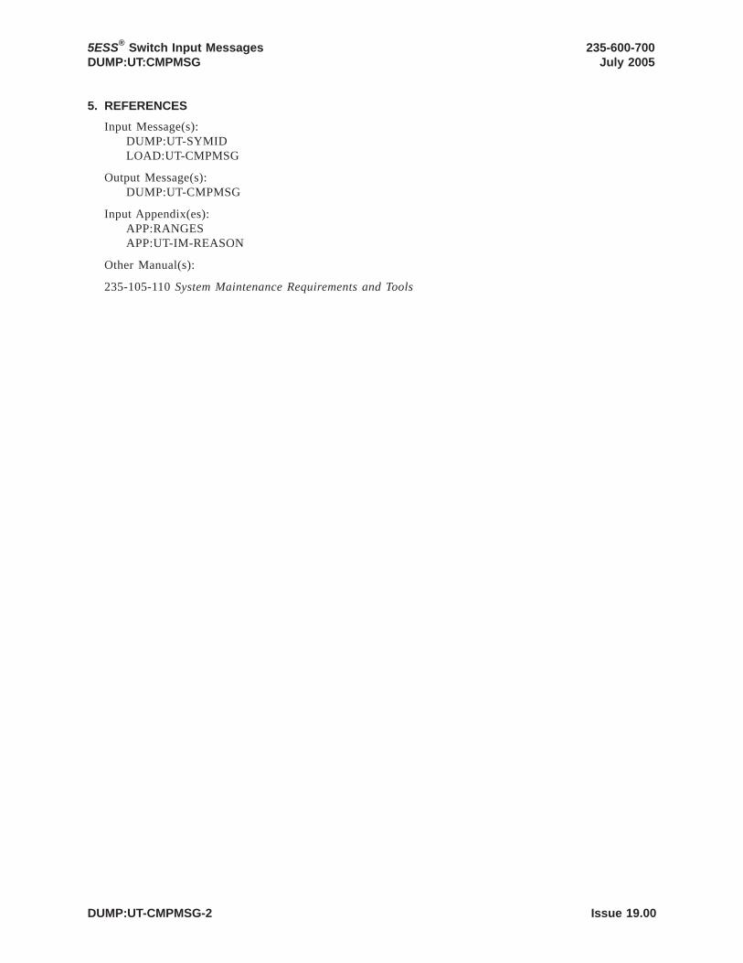
5. REFERENCES
Input Message(s):DUMP:UT-SYMIDLOAD:UT-CMPMSG
Output Message(s):DUMP:UT-CMPMSG
Input Appendix(es):APP:RANGESAPP:UT-IM-REASON
Other Manual(s):
235-105-110 System Maintenance Requirements and Tools
5ESS® Switch Input MessagesDUMP:UT:CMPMSG
235-600-700July 2005
DUMP:UT-CMPMSG-2 Issue 19.00

ID . . . . . . . . . . . . . . . . . . . . . . . . . . DUMP:UT-DNUSRELEASE . . . . . . . . . . . . . . . . . . 5E15 and laterCOMMAND GROUP . . . . . .APPLICATION . . . . . . . . . . . . 5
1. PURPOSE
Requests that the contents of one or more sequential memory locations in the specified digitalnetworking unit - synchronous optical network (SONET) (DNU-S) common controller (CC) bedumped.
Warning: The user is responsible for any effects on system operation that result from the use ofthis input message. Know the effects of the message before using it.
2. FORMATDUMP:UT:DNUS=a-b[,MATE][,DIS][,EA][,L=c],{ADDR=d|UVAR=e|GVAR="f"|SYMIDX=g}[,INDIR=h][,OFF=i[-i[-i]]]{!|;}
3. EXPLANATION OF MESSAGE
DIS = Dump data in disassembled format.
EA = Dump the effective address of the specified field instead of the contents.
MATE = Dump the contents of the standby DNU-S CC’s memory starting at the final calculatedaddress. (Default: dump active memory.)
a = Switching module (SM) number.
b = DNU-S number.
c = Length in bytes of the dump. Maximum length is 248 bytes. Default is 4 bytes forUVAR, 1 byte for ADDR, GVAR and SYMIDX.
d = Absolute address of location to start the dump or the starting point for indirectaddressing to the start of the dump.
e = Number of the utility variable (0 - 10) whose contents are to be dumped.
f = Symbolic name of the global variable or function to be used to determine a startingaddress. The name is entered as a string of up to 15 characters, enclosed in doublequotation marks. If the symbol name is greater than 15 characters the symbol indexnumber ’g’ must be used to enter this input message using symbolic access. The globalvariable’s symbol index number can be determined by using the DUMP:UT-SYMID inputmessage.
g Symbol index number of this global variable. The symbol index can be determined forthis processor by using the DUMP:UT-SYMID input message.
h = Number of levels of indirection to be calculated by generic utilities (range 0-3) (defaultis 0).
i = The offset, in bytes, at each level of indirection. They can range from 0-65535.However, offsets greater than 32767 will be treated as negative offsets. One offset can bespecified per each level of indirection (maximum is 3) (default is 0).
4. SYSTEM RESPONSE
Refer to the APP:UT-IM-REASON appendix in the Appendixes section of the Input Messages manual.
235-600-700July 2005
5ESS® Switch Input MessagesDUMP:UT:DNUS
**WARNING**INAPPROPRIATE USE OF THIS MESSAGEMAY INTERRUPT OR DEGRADE SERVICE.
READ PURPOSE CAREFULLY.
Issue 19.00 DUMP:UT-DNUS-1

5. REFERENCES
Input Message(s):DUMP:UT-SYMIDEXC:UT-DNUSLOAD:UT-DNUS
Output Message(s):DUMP:UT-DNUS
Input Appendix(es):APP:UT-IM-REASON
Other Manual(s):
235-105-110 System Maintenance Requirements and Tools
5ESS® Switch Input MessagesDUMP:UT:DNUS
235-600-700July 2005
DUMP:UT-DNUS-2 Issue 19.00

ID . . . . . . . . . . . . . . . . . . . . . . . . . . DUMP:UT-FPCRELEASE . . . . . . . . . . . . . . . . . . 5E15 and laterCOMMAND GROUP . . . . . . SFTUTILAPPLICATION . . . . . . . . . . . . 5
1. PURPOSE
Requests that the contents of one or more sequential memory location in the specified foundationperipheral controller (FPC) be dumped.
Warning: The user is responsible for any effects on system operation that result from the use ofthis input message. Know the effects of the message before using it.
NOTE: This input message is valid on processors of the communications module model 1 and 2. Itwill be accepted but denied on the communications module model 3. Use the DUMP:UT:MSGS APinput message for equivalent functionality on processors of the communications module model 3.
2. FORMATDUMP:UT:FPC=a[{,DIS|,EA}],{ADDR=b|IO=c|GVAR="d"|SYMIDX=e}[,L=f][,INDIR=g][,OFF=h[-h[-h]]];
3. EXPLANATION OF MESSAGE
DIS = Dump the data in a disassembled format.
EA = Dump the effective address of the specified field instead of the contents.
a = FPC number.
b = Absolute address of the location to start the dump or the starting point for indirectaddressing to the start of the dump.
c = The number of the I/O port to be dumped.
d = Symbolic name of the global variable or function to be used to determine a startingaddress. The name is entered as a string of up to 15 characters, enclosed in doublequotation marks. If the symbol name is greater than 15 characters the symbol indexnumber ’e’ must be used to enter this input message using symbolic access. The globalvariable’s symbol index number can be determined by using the DUMP:UT-SYMID inputmessage.
e = Symbol index number of this global variable. The symbol index can be determined forthis processor by using the DUMP:UT-SYMID input message.
f = Length in bytes of the dump (1 - 192 bytes, default is 1).
g = The number of levels of indirection to be calculated by generic utilities (0 - 3, defaultis 0).
h = The offsets, in bytes, at each level of indirection (0 - 65535, default is 0). Themaximum number of offsets is 3.
4. SYSTEM RESPONSE
Refer to the APP:UT-IM-REASON appendix in the Appendixes section of the Input Messages manual.
5. REFERENCES
Input Message(s):DUMP:UT-SYMID
235-600-700July 2005
5ESS® Switch Input MessagesDUMP:UT:FPC
**WARNING**INAPPROPRIATE USE OF THIS MESSAGEMAY INTERRUPT OR DEGRADE SERVICE.
READ PURPOSE CAREFULLY.
Issue 19.00 DUMP:UT-FPC-1

Output Message(s):DUMP:UT-FPC
Input Appendix(es):APP:UT-IM-REASON
Other Manual(s):
235-105-110 System Maintenance Requirements and Tools
5ESS® Switch Input MessagesDUMP:UT:FPC
235-600-700July 2005
DUMP:UT-FPC-2 Issue 19.00

ID . . . . . . . . . . . . . . . . . . . . . . . . . . DUMP:UT-IDCULSIRELEASE . . . . . . . . . . . . . . . . . . 5E15 and laterCOMMAND GROUP . . . . . . SFTUTILAPPLICATION . . . . . . . . . . . . 5
1. PURPOSE
Requests that the contents of one or more sequential memory locations in the specified integrateddigital carrier unit (IDCU) loop side interface (LSI) be dumped.
Warning: The user is responsible for any effects on system operation that result from the use ofthis input message. Know the effects of the message before using it.
2. FORMATDUMP:UT:IDCULSI=a-b-c[,MATE][,DIS][,EA][,L=d]{,ADDR=e|,UVAR=f|,GVAR="g"|,SYMIDX=h}[,INDIR=i][,OFF=j[-j[-j]]];
3. EXPLANATION OF MESSAGE
DIS = Dump data in disassembled format.
EA = Dump the effective address of the specified field instead of the contents.
MATE = Dump the contents of the standby LSI’s memory starting at the final calculated address.(Default: dump active memory.)
a = Switching module (SM) number. Refer to the APP:RANGES appendix in theAppendixes section of the Input Messages manual.
b = IDCU number. Refer to the APP:RANGES appendix in the Appendixes section of theInput Messages manual.
c = LSI number. Refer to the APP:RANGES appendix in the Appendixes section of theInput Messages manual.
d = Length in bytes of the dump. Maximum length is 64. Default is 4 bytes for UVAR, 1byte for ADDR, GVAR and SYMIDX.
Note: The dumping and loading of the unified control interface (UCI) register areacannot overlap with the remainder of the IDCU LSI address range (variable ’e’).
e = Absolute address of location to start the dump or the starting point for indirectaddressing to the start of the dump. The address range from 0x4400 to 0x44ff is the UCIregister area.
f = Number of the utility variable whose contents are to be dumped. Refer to theAPP:RANGES appendix in the Appendixes section of the Input Messages manual.
g = Symbolic name of the global variable or function to be used to determine a startingaddress. The name is entered as a string of up to 15 characters, enclosed in doublequotation marks. If the symbol name is greater than 15 characters the symbol indexnumber ’h’ must be used to enter this input message using symbolic access. The globalvariable’s symbol index number can be determined by using the DUMP:UT-SYMID inputmessage.
h = Symbol index number of this global variable. The symbol index can be determined forthis processor by using the DUMP:UT-SYMID input message.
i = Number of levels of indirection to be calculated by generic utilities. Indirection is notallowed when dumping the UCI register area (variable ’e’) (range is 0-3) (default is 0).
j = The offset, in bytes, at each level of indirection. They can range from 0-65535.
235-600-700July 2005
5ESS® Switch Input MessagesDUMP:UT:IDCULSI
**WARNING**INAPPROPRIATE USE OF THIS MESSAGEMAY INTERRUPT OR DEGRADE SERVICE.
READ PURPOSE CAREFULLY.
Issue 19.00 DUMP:UT-IDCULSI-1

However, offsets greater than 32767 will be treated as negative offsets. One offset can bespecified per each level of indirection. Maximum number of offsets is 3. Default is 0.
4. SYSTEM RESPONSE
Refer to the APP:UT-IM-REASON appendix in the Appendixes section of the Input Messages manual.
5. REFERENCES
Input Message(s):DUMP:UT-SYMIDEXC:UT-IDCULSILOAD:UT-IDCULSI
Output Message(s):DUMP:UT-IDCULSI
Input Appendix(es):APP:RANGESAPP:UT-IM-REASON
Other Manual(s):
235-105-110 System Maintenance Requirements and Tools
5ESS® Switch Input MessagesDUMP:UT:IDCULSI
235-600-700July 2005
DUMP:UT-IDCULSI-2 Issue 19.00

ID . . . . . . . . . . . . . . . . . . . . . . . . . . DUMP:UT-IDCURELEASE . . . . . . . . . . . . . . . . . . 5E15 and laterCOMMAND GROUP . . . . . . SFTUTILAPPLICATION . . . . . . . . . . . . 5
1. PURPOSE
Requests that the contents of one or more sequential memory locations in the specified integrateddigital carrier unit (IDCU) be dumped.
Warning: The user is responsible for any effects on system operation that result from the use ofthis input message. Know the effects of the message before using it.
2. FORMATDUMP:UT:IDCU=a-b[,MATE][,DIS][,EA][,L=c],{ADDR=d|UVAR=e|GVAR="f"|SYMIDX=g}[,INDIR=h][,OFF=i[-i[-i]]];
3. EXPLANATION OF MESSAGE
DIS = Dump data in disassembled format.
EA = Dump the effective address of the specified field instead of the contents.
MATE = Dump the contents of the standby IDCU’s memory starting at the final calculatedaddress. (Default: dump active memory.)
a = Switching module (SM) number. Refer to the APP:RANGES appendix in theAppendixes section of the Output Messages manual.
b = IDCU number. Refer to the APP:RANGES appendix in the Appendixes section of theOutput Messages manual.
c = Length in bytes of the dump. Maximum length is 64. Default is 4 bytes for UVAR, 1byte for ADDR, GVAR and SYMIDX.
Note: The dumping and loading of the unified control interface (UCI) register areacannot overlap with the remainder of the IDCU address range (variable ’d’).
d = Absolute address of location to start the dump or the starting point for indirectaddressing to the start of the dump. The address range from h’30000332 to h’300003ff isthe UCI register area.
e = Number of the utility variable whose contents are to be dumped. Refer to theAPP:RANGES appendix in the Appendixes section of the Input Messages manual.
f = Symbolic name of the global variable or function to be used to determine a startingaddress. The name is entered as a string of up to 15 characters, enclosed in doublequotation marks. If the symbol name is greater than 15 characters the symbol indexnumber ’g’ must be used to enter this input message using symbolic access. The globalvariable’s symbol index number can be determined by using the DUMP:UT-SYMID inputmessage.
g = Symbol index number of this global variable. The symbol index can be determined forthis processor by using the DUMP:UT-SYMID input message.
h = Number of levels of indirection to be calculated by generic utilities. Indirection is notallowed when dumping the UCI register area (variable ’d’) (default is 0). Refer to theAPP:RANGES appendix in the Appendixes section of the Input Messages manual.
i = The offset, in bytes, at each level of indirection. They can range from 0-65535.However, offsets greater than 32767 will be treated as negative offsets. One offset can bespecified per each level of indirection (maximum is 3) (default is 0).
235-600-700July 2005
5ESS® Switch Input MessagesDUMP:UT:IDCU
**WARNING**INAPPROPRIATE USE OF THIS MESSAGEMAY INTERRUPT OR DEGRADE SERVICE.
READ PURPOSE CAREFULLY.
Issue 19.00 DUMP:UT-IDCU-1

4. SYSTEM RESPONSE
Refer to the APP:UT-IM-REASON appendix in the Appendixes section of the Input Messages manual.
5. REFERENCES
Input Message(s):DUMP:UT-SYMIDEXC:UT-IDCULOAD:UT-IDCU
Output Message(s):DUMP:UT-IDCU
Input Appendix(es):APP:RANGESAPP:UT-IM-REASON
5ESS® Switch Input MessagesDUMP:UT:IDCU
235-600-700July 2005
DUMP:UT-IDCU-2 Issue 19.00

ID . . . . . . . . . . . . . . . . . . . . . . . . . . DUMP:UT-ISLUCCRELEASE . . . . . . . . . . . . . . . . . . 5E15 and laterCOMMAND GROUP . . . . . . SFTUTILAPPLICATION . . . . . . . . . . . . 5
1. PURPOSE
Requests that the contents of one or more sequential memory locations in the specified integratedservices line unit common controller (ISLUCC) be dumped.
Warning: The user is responsible for any effects on system operation that result from the use ofthis input message. Know the effects of the message before using it.
2. FORMATDUMP:UT:ISLUCC=a-b[,MATE][,DIS][,EA][,L=c]{,ADDR=d|,UVAR=e|,GVAR="f"|,SYMIDX=g}[,INDIR=h][,OFF=i[-i[-i]]];
3. EXPLANATION OF MESSAGE
DIS = Dump data in disassembled format.
EA = Dump the effective address of the specified field instead of the contents.
MATE = Dump the contents of the standby ISLUCC’s memory starting at the final calculatedaddress. (Default: dump active memory.)
a = Switching module (SM) number.
b = Line unit number.
c = Length in bytes of the dump (1 - 64). Default is 4 bytes for UVAR, 1 byte for ADDR,GVAR and SYMIDX. The dumping and loading of the unified control interface (UCI)register area cannot overlap with the remainder of the common control (CC) addressrange (variable ’d’).
d = Absolute address of location to start the dump or the starting point for indirectaddressing to the start of the dump. The address range from H’4532 to H’45ff is the UCIregister area.
e = Number of the utility variable whose contents are to be dumped. Refer to theAPP:RANGES appendix in the Appendixes section of the Input Messages manual.
f = Symbolic name of the global variable or function to be used to determine a startingaddress. The name is entered as a string of up to 15 characters, enclosed in doublequotation marks. If the symbol name is greater than 15 characters the symbol indexnumber ’g’ must be used to enter this input message using symbolic access. The globalvariable’s symbol index number can be determined by using the DUMP:UT-SYMID inputmessage.
g = Symbol index number of this global variable. The symbol index can be determined forthis processor by using the DUMP:UT-SYMID input message.
h = Number of levels of indirection to be calculated by generic utilities. Indirection is notallowed when dumping the UCI register area (variable ’d’) (range is 0-3) (default is 0).
i = The offset, in bytes, at each level of indirection (range is 0-65535) (default is 0)(maximum offsets is 3).
4. SYSTEM RESPONSE
Refer to the APP:UT-IM-REASON appendix in the Appendixes section of the Input Messages manual.
235-600-700July 2005
5ESS® Switch Input MessagesDUMP:UT:ISLUCC
**WARNING**INAPPROPRIATE USE OF THIS MESSAGEMAY INTERRUPT OR DEGRADE SERVICE.
READ PURPOSE CAREFULLY.
Issue 19.00 DUMP:UT-ISLUCC-1

5. REFERENCES
Input Message(s):DUMP:UT-SYMIDEXC:UT-ISLUCCLOAD:UT-ISLUCC
Output Message(s):DUMP:UT-ISLUCC
Input Appendix(es):APP:RANGESAPP:UT-IM-REASON
Other Manual(s):
235-105-110 System Maintenance Requirements and Tools
5ESS® Switch Input MessagesDUMP:UT:ISLUCC
235-600-700July 2005
DUMP:UT-ISLUCC-2 Issue 19.00

ID . . . . . . . . . . . . . . . . . . . . . . . . . . DUMP:UT-MCTSI-MHRELEASE . . . . . . . . . . . . . . . . . . 5E15 and laterCOMMAND GROUP . . . . . . SFTUTILAPPLICATION . . . . . . . . . . . . 5
1. PURPOSE
Requests that the contents of one or more sequential memory locations in the specified messagehandler (MH) unit be dumped.
Warning: The user is responsible for any effects on system operation that result from the use ofthis input message. Know the effects of the message before using it.
2. FORMATDUMP:UT:MCTSI=a-b,MH[,MATE][,DIS][,EA][,L=c],{ADDR=d|UVAR=e|GVAR="f"|SYMIDX=g}[,INDIR=h][,OFF=i[-i][-i]]{!|;}
3. EXPLANATION OF MESSAGE
DIS = Dump the data in disassembled format.
EA = Dump the effective address of the specified field instead of the contents.
MATE = Dump the contents of the standby MH’s memory starting at the final calculated address.Default is active MH memory.
a = Switching module (SM) number. Refer to the APP:RANGES appendix in theAppendixes section of the Input Messages manual.
b = Message handler unit number. Refer to the APP:RANGES appendix in the Appendixessection of the Input Messages manual.
c = Length in bytes of the dump (1-1000). Default is 4 bytes for UVAR, 1 byte for ADDR,GVAR and SYMIDX.
d = Absolute address of location to start the dump or the starting point for indirectaddressing.
e = Number of the utility variable UVAR (0-10) whose data is to be dumped.
f = Symbolic name of the global variable or function to be used to determine a startingaddress. The name is entered as a string of up to 15 characters, enclosed in doublequotation marks. If the symbol name is greater than 15 characters the symbol indexnumber ’g’ must be used to enter this input message using symbolic access. The globalvariable’s symbol index number can be determined by using the DUMP:UT-SYMID inputmessage.
g = Symbol index number of this global variable. The symbol index can be determined forthis processor by using the DUMP:UT-SYMID input message.
h = The number of levels of indirection to be calculated by generic utilities (range is 0-3)(default is 0).
i = The offsets, in bytes, at each level of indirection (range is 0-65535) (default is 0).However, offsets greater than 32767 will be treated as negative offsets. One offset can bespecified per each level of indirection. Maximum number of offsets is 3.
4. SYSTEM RESPONSE
Refer to the APP:UT-IM-REASON appendix in the Appendixes section of the Input Messages manual.
235-600-700July 2005
5ESS® Switch Input MessagesDUMP:UT
**WARNING**INAPPROPRIATE USE OF THIS MESSAGEMAY INTERRUPT OR DEGRADE SERVICE.
READ PURPOSE CAREFULLY.
Issue 19.00 DUMP:UT-MCTSI-MH-1

5. REFERENCES
Input Message(s):DUMP:UT-SYMIDEXC:UT-MCTSI-MHLOAD:UT-MCTSI-MH
Output Message(s):DUMP:UT-MCTSI-MH
Input Appendix(es):APP:RANGESAPP:UT-IM-REASON
Other Manual(s):
235-105-110 System Maintenance Requirements and Tools
5ESS® Switch Input MessagesDUMP:UT
235-600-700July 2005
DUMP:UT-MCTSI-MH-2 Issue 19.00

ID . . . . . . . . . . . . . . . . . . . . . . . . . . DUMP:UT-MCTSI-PI-ARELEASE . . . . . . . . . . . . . . . . . . 5E15 onlyCOMMAND GROUP . . . . . . SFTUTILAPPLICATION . . . . . . . . . . . . 5
1. PURPOSE
Requests that the contents of one or more sequential memory locations in the specified packetinterface (PI) unit be dumped.
Format 2 requests that a function trace be performed in the specified PI unit. This input message canonly be used in a WHEN input message clause.
Note: Format 2 is only supported on PIs of the PI2 hardware type.
Warning: The user is responsible for any effects on system operation that result from the use ofthis input message. Know the effects of the message before using it.
2. FORMAT[1] DUMP:UT:MCTSI=a-b,PI[,DIS][,EA][,L=c]
,{ADDR=d|UVAR=e|REG=f|REGS|GVAR="g"|SYMIDX=h}[,INDIR=h][,OFF=i[-i[-i]]]{!|;}
[2] DUMP:UT:MCTSI=a-b,PI,FTRACE{!|;}
3. EXPLANATION OF MESSAGE
DIS = Dump data in disassembled format.
EA = Dump the effective address of the specified field instead of the contents.
a = Switching module (SM) number.
b = Side of the module controller/time-slot interchange (MCTSI).
c = Total length in bytes of the dump. Maximum length is 1000 bytes for PIs of PI1 type.For PIs of PI2 type the maximum length is 32767. Default is 4 bytes for UVAR, 1 bytefor ADDR, GVAR and SYMIDX.
d = Absolute address of location to start the dump or the starting point for indirectaddressing to the start of the dump.
e = Number of the utility variable UVAR (0-14) whose contents are to be dumped for PIsof PI2 type. For PIs of PI1 type the utility variables are (0-11).
Note: The REG and REGS option is only supported on PIs of the PI2 hardware type.
f Dumps data from a specific register (address registers A1-A7, data registers D0-D7,program counter PC, or status register SR). If the data is dumped outside of a WHENclause, a dummy set of registers is used.
g = Symbolic name of the global variable or function to be used to determine a startingaddress. The name is entered as a string of up to 15 characters, enclosed in doublequotation marks. If the symbol name is greater than 15 characters the symbol indexnumber ’h’ must be used to enter this input message using symbolic access. The globalvariable’s symbol index number can be determined by using the DUMP:UT-SYMID inputmessage.
h = Symbol index number of this global variable. The symbol index can be determined forthis processor by using the DUMP:UT-SYMID input message.
i = Number of levels of indirection to be calculated by generic utilities (range is 0-3)(default is 0).
235-600-700July 2005
5ESS® Switch Input MessagesDUMP:UT
**WARNING**INAPPROPRIATE USE OF THIS MESSAGEMAY INTERRUPT OR DEGRADE SERVICE.
READ PURPOSE CAREFULLY.
Issue 19.00 DUMP:UT-MCTSI-PI-A-1

j = The offset, in bytes, at each level of indirection. (range is 0-65535) (default is 0)(maximum offsets is 3). In the PI1, offsets can range from 0-65535 in the positivedirection. In the PI2, offsets can range from 0-65535. However, offsets greater than 32767will be treated as negative offsets.
4. SYSTEM RESPONSE
Refer to the APP:UT-IM-REASON appendix in the Appendixes section of the Input Messages manual.
5. REFERENCES
Input Message(s):ALW:UT-MCTSI-PICLR:UT-MCTSI-PIDUMP:UT-SYMIDELSE:UT-MCTSI-PIEND:UT-MCTSI-PIEXC:UT-MCTSI-PIIF:UT-MCTSI-PIINH:UT-MCTSI-PILOAD:UT-MCTSI-PIOP:UT-MCTSI-PIWHEN:UT-MCTSI-PI
Output Message(s):DUMP:UT-MCTSI-PIREPT:STACK-TRACE
Input Appendix(es):APP:UT-IM-REASON
Other Manual(s):
235-105-110 System Maintenance Requirements and Tools
5ESS® Switch Input MessagesDUMP:UT
235-600-700July 2005
DUMP:UT-MCTSI-PI-A-2 Issue 19.00

ID . . . . . . . . . . . . . . . . . . . . . . . . . . DUMP:UT-MCTSI-PI-BRELEASE . . . . . . . . . . . . . . . . . . 5E16(1) and laterCOMMAND GROUP . . . . . . SFTUTILAPPLICATION . . . . . . . . . . . . 5
1. PURPOSE
Requests that the contents of one or more sequential memory locations in the specified packetinterface (PI) unit be dumped.
Format 2 requests that a function trace be performed in the specified PI unit. This input message canonly be used in a WHEN input message clause.
Note: Format 2 is only supported on PIs of the PI2 hardware type.
Warning: The user is responsible for any effects on system operation that result from the use ofthis input message. Know the effects of the message before using it.
2. FORMAT[1] DUMP:UT:MCTSI=a-b,PI[,DIS][,EA][,L=c]
,{ADDR=d|UVAR=e|REG=f|REGS|GVAR="g"|SYMIDX=h}[,INDIR=h][,OFF=i[-i[-i]]]{!|;}
[2] DUMP:UT:MCTSI=a-b,PI,FTRACE{!|;}
3. EXPLANATION OF MESSAGE
DIS = Dump data in disassembled format.
EA = Dump the effective address of the specified field instead of the contents.
a = Switching module (SM) number.
b = Side of the module controller/time-slot interchange (MCTSI).
c = Total length in bytes of the dump. Maximum length is 1000 bytes.
d = Absolute address of location to start the dump or the starting point for indirectaddressing to the start of the dump.
e = Number of the utility variable UVAR (0-14) whose contents are to be dumped for PIsof PI2 type. For PIs of PI1 type the utility variables are (0-11).
Note: The REG and REGS option is only supported on PIs of the PI2 hardwaretype.
f Dumps data from a specific register (address registers A1-A7, data registers D0-D7,program counter PC, or status register SR). If the data is dumped outside of a WHENclause, a dummy set of registers is used.
g = Symbolic name of the global variable or function to be used to determine a startingaddress. The name is entered as a string of up to 15 characters, enclosed in doublequotation marks. If the symbol name is greater than 15 characters the symbol indexnumber ’h’ must be used to enter this input message using symbolic access. The globalvariable’s symbol index number can be determined by using the DUMP:UT-SYMID inputmessage.
h = Symbol index number of this global variable. The symbol index can be determined forthis processor by using the DUMP:UT-SYMID input message.
i = Number of levels of indirection to be calculated by generic utilities (range is 0-3)(default is 0).
j = The offset, in bytes, at each level of indirection. (range is 0-65535) (default is 0)(maximum offsets is 3). In the PI1, offsets can range from 0-65535 in the positive
235-600-700July 2005
5ESS® Switch Input MessagesDUMP:UT
**WARNING**INAPPROPRIATE USE OF THIS MESSAGEMAY INTERRUPT OR DEGRADE SERVICE.
READ PURPOSE CAREFULLY.
Issue 19.00 DUMP:UT-MCTSI-PI-B-1

direction. In the PI2, offsets can range from 0-65535. However, offsets greater than 32767will be treated as negative offsets.
4. SYSTEM RESPONSE
Refer to the APP:UT-IM-REASON appendix in the Appendixes section of the Input Messages manual.
5. REFERENCES
Input Message(s):ALW:UT-MCTSI-PICLR:UT-MCTSI-PIDUMP:UT-SYMIDELSE:UT-MCTSI-PIEND:UT-MCTSI-PIEXC:UT-MCTSI-PIIF:UT-MCTSI-PIINH:UT-MCTSI-PILOAD:UT-MCTSI-PIOP:UT-MCTSI-PIWHEN:UT-MCTSI-PI
Output Message(s):DUMP:UT-MCTSI-PIREPT:STACK-TRACE
Input Appendix(es):APP:UT-IM-REASON
Other Manual(s):
235-105-110 System Maintenance Requirements and Tools
5ESS® Switch Input MessagesDUMP:UT
235-600-700July 2005
DUMP:UT-MCTSI-PI-B-2 Issue 19.00

ID . . . . . . . . . . . . . . . . . . . . . . . . . . DUMP:UT-MMPRELEASE . . . . . . . . . . . . . . . . . . 5E15 and laterCOMMAND GROUP . . . . . . SFTUTILAPPLICATION . . . . . . . . . . . . 5
1. PURPOSE
Requests that the contents of one or more sequential memory locations in the specified modulemessage processor (MMP) be dumped.
Warning: The user is responsible for any effects on system operation that result from the use ofthis input message. Know the effects of the message before using it.
NOTE: This input message is valid on processors of the communications module model 1 and 2. Itwill be accepted but denied on the communications module model 3. Use the DUMP:UT:MSGS APinput message for equivalent functionality on processors of the communications module model 3.
2. FORMATDUMP:UT:MMP=a-b[{,DIS|,EA}],{ADDR=c|IO=d|GVAR="e"|SYMIDX=f}[,L=g][,INDIR=h][,OFF=i[-i[-i]]];
3. EXPLANATION OF MESSAGE
DIS = Dump the data in a disassembled format.
EA = Dump the effective address of the specified field instead of the contents.
a = Message switch side. Refer to the APP:RANGES appendix in the Appendixes section ofthe Input Messages manual.
b = MMP number.
c = Absolute address of location to start the dump or the starting point for indirectaddressing to the start of the dump.
d = The number of the I/O port to be dumped.
e = Symbolic name of the global variable or function to be used to determine a startingaddress. The name is entered as a string of up to 15 characters, enclosed in doublequotation marks. If the symbol name is greater than 15 characters the symbol indexnumber ’f’ must be used to enter this input message using symbolic access. The globalvariable’s symbol index number can be determined by using the DUMP:UT-SYMID inputmessage.
f = Symbol index number of this global variable. The symbol index can be determined forthis processor by using the DUMP:UT-SYMID input message.
g = Length in bytes of dump. Maximum length is 192 bytes. Default is 1 byte.
h = The number of levels of indirection to be calculated by generic utilities (range is 0-3)(default is 0).
i = The offset, in bytes, at each level of indirection. (range is 0-65535) (default is 0)(maximum offsets is 3).
4. SYSTEM RESPONSE
Refer to the APP:UT-IM-REASON appendix in the Appendixes section of the Input Messages manual.
235-600-700July 2005
5ESS® Switch Input MessagesDUMP:UT:MMP
**WARNING**INAPPROPRIATE USE OF THIS MESSAGEMAY INTERRUPT OR DEGRADE SERVICE.
READ PURPOSE CAREFULLY.
Issue 19.00 DUMP:UT-MMP-1

5. REFERENCES
Input Message(s):DUMP:UT-SYMIDEXC:UT-MMPLOAD:UT-MMP
Input Appendix(es):APP:RANGESAPP:UT-IM-REASON
Other Manual(s):
235-105-110 System Maintenance Requirements and Tools
5ESS® Switch Input MessagesDUMP:UT:MMP
235-600-700July 2005
DUMP:UT-MMP-2 Issue 19.00

ID . . . . . . . . . . . . . . . . . . . . . . . . . . DUMP:UT-MSGSRELEASE . . . . . . . . . . . . . . . . . . 5E15 and laterCOMMAND GROUP . . . . . . SFTUTILAPPLICATION . . . . . . . . . . . . 5
1. PURPOSE
Requests that the contents of one or more sequential memory locations in the specified message switch(MSGS) be dumped.
NOTE: This command is valid only on MSGS processors of communication Model 3.
2. FORMATDUMP:UT:MSGS=a,{AP|IP}[,DIS][,EA,{ADDR=b|GVAR="c"|SYMIDX=d|UVAR=e}[,L=f][,INDIR=g][,OFF=h[-h][-h]];
3. EXPLANATION OF MESSAGE
AP = Dump the contents of the MSGS application processor’s memory starting at the finalcalculated address.
DIS = Dump the data in a disassembled format.
EA = Dump the effective address of the specified field instead of the contents.
IP = Dump the contents of the MSGS interface processor’s memory starting at the finalcalculated address.
a = Message switch side. Refer to the APP:RANGES appendix in the Appendixes section ofthe Input Messages manual.
b = Absolute address of location to start the dump (unless indirection has been specified).
c = Symbolic name of the global variable or function to be used to determine a startingaddress. The name is entered as a string of up to 15 characters, enclosed in doublequotation marks. If the symbol name is greater than 15 characters the symbol indexnumber ’d’ must be used to enter this command using symbolic access. The globalvariable’s symbol index number can be determined by using the DUMP:UT-SYMID inputcommand.
d = Symbol index number of this global variable. The symbol index can be determined forthis processor by using the DUMP:UT-SYMID input command.
e = Number of the utility variable UVAR (0-10) whose data is to be dumped.
f = Length in bytes of the dump (1 - 192 bytes). Default is 4 bytes for UVAR, 1 byte forADDR, GVAR, and SYMIDX.
g = The number of levels of indirection to be calculated by generic utilities (0 - 3, default= 0).
h = The offsets, in bytes, at each level of indirection (0 - 65535). Offsets greater than32767 will be treated as negative offsets. One offset can be specified per each level ofindirection. Maximum number of offsets is 3. Default is 0.
4. SYSTEM RESPONSE
Refer to the APP:UT-IM-REASON appendix in the Appendixes section of the Input Messages manual.
235-600-700July 2005
5ESS® Switch Input MessagesDUMP:UT
Issue 19.00 DUMP:UT-MSGS-1

5. REFERENCES
Input Message(s):DUMP:UT-SYMID
Output Message(s):DUMP:UT-MSGS
Input Appendix(es):APP:RANGESAPP:UT-IM-REASON
Other Manual(s):
System Maintenance Requirements and Tools
5ESS® Switch Input MessagesDUMP:UT
235-600-700July 2005
DUMP:UT-MSGS-2 Issue 19.00

ID . . . . . . . . . . . . . . . . . . . . . . . . . . DUMP:UT-OFIRELEASE . . . . . . . . . . . . . . . . . . 5E16(1) and laterCOMMAND GROUP . . . . . . SFTUTILAPPLICATION . . . . . . . . . . . . 5
1. PURPOSE
Requests that the contents of one more sequential memory locations in the specified optical facilityinterface (OFI) be dumped.
This request may be used together with any of the other OFI generic utility input requests (refer to theREFERENCES section).
Warning: The user takes responsibility for any effects on system operation that result from the useof this input request. Know the effects of the request before using it.
2. FORMATDUMP:UT:OFI=a-b-c-d[,DIS][,EA][,L=e],{ADDR=f|UVAR=g|GVAR="h"|SYMIDX=i}. . .. . .[,INDIR=j][,OFF=k[-k][-k]]{!|;}
3. EXPLANATION OF MESSAGE
DIS = Dump the data in a disassembled format.
EA = Dump the effective address of the specified field instead of the contents.
a = Switching module (SM) number. Refer to the APP:RANGES appendix in theAppendixes section of the Input Messages manual.
b = Optical Interface Unit (OIU) number. Refer to the APP:RANGES appendix in theAppendixes section of the Input Messages manual.
c = Protection group number. Refer to the APP:RANGES appendix in the Appendixessection of the Input Messages manual.
d = Side number.
e = Length in bytes of the dump. The maximum dump length for an OFI is 248. Default is4 bytes for utility variable (UVAR), 1 byte for ADDR, GVAR and SYMIDX.
f = Absolute address of location to start the dump or the starting point for indirectaddressing to the start of the dump.
g = Number of the UVAR (0 - 10) whose contents are to be dumped.
h = Symbolic name of the global variable or function to be used to determine a startingaddress. The name is entered as a string of up to 15 characters, enclosed in doublequotation marks. If the symbol name is greater than 15 characters the symbol indexnumber ’i’ must be used to enter this input request using symbolic access. The globalvariable’s symbol index number can be determined by using the DUMP:UT:SYMID inputrequest.
i = Symbolic index number of this global variable. The symbol index can be determinedfor this processor by using the DUMP:UT-SYMID input request.
j = The number of levels of indirection to be calculated by generic utilities (0 - 3, defaultis 0).
k = The offsets, in bytes, at each level of indirection (default is 0). One offset can bespecified per each level of indirection. Maximum number of offsets is 3.
Note: Offsets can range from 0-65535. However, offsets greater than 32767 will betreated as negative offsets.
235-600-700July 2005
5ESS® Switch Input MessagesDUMP:UT
**WARNING**INAPPROPRIATE USE OF THIS MESSAGEMAY INTERRUPT OR DEGRADE SERVICE.
READ PURPOSE CAREFULLY.
Issue 19.00 DUMP:UT-OFI-1

4. SYSTEM RESPONSE
Refer to the APP:UT-IM-REASON appendix in the Appendixes section of the Input Messages manual.
5. REFERENCES
Input Message(s):DUMP:UT-SYMIDEXC:UT-OFILOAD:UT-OFI
Output Message(s):DUMP:UT-OFI
Input Appendix(es):APP:RANGESAPP:UT-IM-REASON
Other Manual(s):
235-105-110 System Maintenance Requirements and Tools
5ESS® Switch Input MessagesDUMP:UT
235-600-700July 2005
DUMP:UT-OFI-2 Issue 19.00

ID . . . . . . . . . . . . . . . . . . . . . . . . . . DUMP:UT-ONTCRELEASE . . . . . . . . . . . . . . . . . . 5E15 and laterCOMMAND GROUP . . . . . . SFTUTILAPPLICATION . . . . . . . . . . . . 5
1. PURPOSE
Requests that the contents of one or more sequential memory locations in the specified office networkand timing complex processor (ONTC) be dumped.
NOTE: This command is valid only on ONTC processors of communication Model 3.
2. FORMATDUMP:UT:ONTC=a,{AP|IP}[,DIS][,EA],{ADDR=b|GVAR="c"|SYMIDX=d|UVAR=e}[,L=f][,INDIR=g][,OFF=h[-h][-h]];
3. EXPLANATION OF MESSAGE
AP = Dump the contents of the ONTC application processor’s memory starting at the finalcalculated address.
DIS = Dump the data in a disassembled format.
EA = Dump the effective address of the specified field instead of the contents.
IP = Dump the contents of the ONTC interface processor’s memory starting at the finalcalculated address.
a = ONTC side. Refer to the APP:RANGES appendix in the Appendixes section of theInput Messages manual. Refer to the APP:RANGES appendix in the Appendixes sectionof the Input Messages manual.
b = Absolute address of location to start the dump (unless indirection has been specified).
c = Symbolic name of the global variable or function to be used to determine a startingaddress. The name is entered as a string of up to 15 characters, enclosed in doublequotation marks. If the symbol name is greater than 15 characters the symbol indexnumber ’d’ must be used to enter this command using symbolic access. The globalvariable’s symbol index number can be determined by using the DUMP:UT-SYMID inputcommand.
d = Symbol index number of this global variable. The symbol index can be determined forthis processor by using the DUMP:UT-SYMID input command.
e = Number of the utility variable UVAR (0-10) whose data is to be dumped.
f = Length in bytes of the dump (1 - 192 bytes). Default is 4 bytes for UVAR, 1 byte forADDR, GVAR, and SYMIDX.
g = The number of levels of indirection to be calculated by generic utilities (0 - 3, default= 0).
h = The offsets, in bytes, at each level of indirection (0 - 65535). Offsets greater than32767 will be treated as negative offsets. One offset can be specified per each level ofindirection. Maximum number of offsets is 3. Default is 0.
4. SYSTEM RESPONSE
Refer to the APP:UT-IM-REASON appendix in the Appendixes section of the Input Messages manual.
235-600-700July 2005
5ESS® Switch Input MessagesDUMP:UT
Issue 19.00 DUMP:UT-ONTC-1

5. REFERENCES
Input Message(s):DUMP:UT-SYMID
Output Message(s):DUMP:UT-ONTC
Input Appendix(es):APP:RANGESAPP:UT-IM-REASON
Other Manual(s):
System Maintenance Requirements and Tools
5ESS® Switch Input MessagesDUMP:UT
235-600-700July 2005
DUMP:UT-ONTC-2 Issue 19.00

ID . . . . . . . . . . . . . . . . . . . . . . . . . . DUMP:UT-PPCRELEASE . . . . . . . . . . . . . . . . . . 5E15 and laterCOMMAND GROUP . . . . . . SFTUTILAPPLICATION . . . . . . . . . . . . 5
1. PURPOSE
Requests that the contents of one or more sequential memory locations in the specified pumpperipheral controller (PPC) be dumped.
Warning: The user is responsible for any effects on system operation that result from the use ofthis input message. Know the effects of the message before using it.
NOTE: This input message is valid on processors of the communications module model 1 and 2. Itwill be accepted but denied on the communications module model 3. Use the DUMP:UT:MSGS APinput message for equivalent functionality on processors of the communications module model 3.
2. FORMATDUMP:UT:PPC=a[{,DIS|,EA}],{ADDR=b|IO=c|GVAR="d"|SYMIDX=e}[,L=f][,INDIR=g][,OFF=h[-h][-h]];
3. EXPLANATION OF MESSAGE
DIS = Dump the data in a disassembled format.
EA = Dump the effective address of the specified field instead of the contents.
a = PPC number.
b = Absolute address of location to start the dump or the starting point for indirectaddressing to the start of the dump.
c = The number of the I/O port to be dumped.
d = Symbolic name of the global variable or function to be used to determine a startingaddress. The name is entered as a string of up to 15 characters, enclosed in doublequotation marks. If the symbol name is greater than 15 characters the symbol indexnumber ’e’ must be used to enter this input message using symbolic access. The globalvariable’s symbol index number can be determined by using the DUMP:UT-SYMID inputmessage.
e = Symbol index number of this global variable. The symbol index can be determined forthis processor by using the DUMP:UT-SYMID input message.
f = Length in bytes of the dump (range is 1-192) (default is 1).
g = The number of levels of indirection to be calculated by generic utilities (range is 0-3)(default is 0).
h = The offset, in bytes, at each level of indirection. (range is 0-65535) (default is 0)(maximum offsets is 3).
4. SYSTEM RESPONSE
Refer to the APP:UT-IM-REASON appendix in the Appendixes section of the Input Messages manual.
5. REFERENCES
Input Message(s):DUMP:UT-SYMID
235-600-700July 2005
5ESS® Switch Input MessagesDUMP:UT:PPC
**WARNING**INAPPROPRIATE USE OF THIS MESSAGEMAY INTERRUPT OR DEGRADE SERVICE.
READ PURPOSE CAREFULLY.
Issue 19.00 DUMP:UT-PPC-1

Output Message(s):EXC:UT-PPCLOAD:UT-PPC
Input Appendix(es):APP:UT-IM-REASON
Other Manual(s):
235-105-110 System Maintenance Requirements and Tools
5ESS® Switch Input MessagesDUMP:UT:PPC
235-600-700July 2005
DUMP:UT-PPC-2 Issue 19.00

ID . . . . . . . . . . . . . . . . . . . . . . . . . . DUMP:UT-PSUPH-ARELEASE . . . . . . . . . . . . . . . . . . 5E15 onlyCOMMAND GROUP . . . . . . SFTUTILAPPLICATION . . . . . . . . . . . . 5
1. PURPOSE
Requests that the contents of one more sequential memory locations in the specified packet switch unitprotocol handler (PSUPH) be dumped.
This request may be used together with any of the other PSUPH generic utility input requests (refer tothe REFERENCES section).
If this request is used together with other generic utility requests, the END:UT-PSUPH input requestmay be used to signal the end of the series of requests.
Format 2 requests that a function trace be performed in the specified PSUPH. This input request canonly be used in a (non-timed) WHEN clause.
Warning: The user takes responsibility for any effects on system operation that result from the useof this input request. Know the effects of the request before using it.
2. FORMAT[1] DUMP:UT:PSUPH=a-b-c-d[,DIS][,EA][,L=e]...
...,{ADDR=f|REG=g|REGS|UVAR=h|GVAR="i"|SYMIDX=j}...
...[,INDIR=k][,OFF=l[-l][-l]]{!|;}[2] DUMP:UT:PSUPH=a-b-c-d,FTRACE{!|;}
3. EXPLANATION OF MESSAGE
DIS = Dump the data in a disassembled format.
EA = Dump the effective address of the specified field instead of the contents.
Note: The REGS and REG options of this input request are only supported in aPSUPH of the PH[3-4,6,22], PHA, PHV[1-5] hardware type (that is, notvalid for PH2 hardware type).
REGS = Dump data from all registers. If the data is dumped outside a WHEN clause, a dummyset of registers is used.
a = Switching module (SM) number. Refer to the APP:RANGES appendix in theAppendixes section of the Input Messages manual.
b = Unit number (always 0).
c = Shelf number. Refer to the APP:RANGES appendix in the Appendixes section of theInput Messages manual.
d = Slot number. Refer to the APP:RANGES appendix in the Appendixes section of theInput Messages manual.
e = Length in bytes of the dump. The maximum dump length for a PSUPH is (1-1000).Default is 4 bytes for utility variable (UVAR) and REG unless REG is the status registerwhich defaults to 2 bytes, 1 byte for ADDR, GVAR and SYMIDX.
f = Absolute address of location to start the dump or the starting point for indirectaddressing.
g = Name of a specific register whose data is to be dumped. The following registers can beused:
235-600-700July 2005
5ESS® Switch Input MessagesDUMP:UT
**WARNING**INAPPROPRIATE USE OF THIS MESSAGEMAY INTERRUPT OR DEGRADE SERVICE.
READ PURPOSE CAREFULLY.
Issue 19.00 DUMP:UT-PSUPH-A-1

- If PSUPH is a PHV5 hardware type, the registers are general purposeregisters GPR0, GPR2-GPR31, the stack pointer SP [which is GPR1], thelink register LR, program counter PC, count register CTR, condition registerCR, machine state register MSR, and the exception register XER.
- If PSUPH is a PH[3-4,6,22], PHA, PHV[1-4] hardware type, the registers areaddress registers A0-A5, A6 [which is the frame pointer FP], A7 [which isthe stack pointer SP], data registers D0-D7, program counter PC, and statusregister SR.
Note: If the data is dumped outside of a WHEN clause, a dummy set of registers isused.
h = Number of the UVAR whose data is to be dumped. The range of UVARs in a PSUPHof the PH2 hardware type is (0-10). For all other PHs, the range of UVARs is (0-14).
i = Symbolic name of the global variable or function to be used to determine a startingaddress. The name is entered as a string of up to 15 characters, enclosed in doublequotation marks. If the symbol name is greater than 15 characters the symbol indexnumber ’j’ must be used to enter this input request using symbolic access. The globalvariable’s symbol index number can be determined by using the DUMP:UT-SYMID inputrequest.
j = Symbol index number of this global variable. The symbol index can be determined forthis processor by using the DUMP:UT-SYMID input request.
k = The number of levels of indirection to be calculated by generic utilities (0 - 3, defaultis 0).
l = The offsets, in bytes, at each level of indirection (default is 0). One offset can bespecified per each level of indirection. Maximum number of offsets is 3.
Note: In the PH2, offsets can range from 0-65535 in the positive direction.
In all other PHs, offsets can range from 0-65535. However, offsets greaterthan 32767 will be treated as negative offsets.
4. SYSTEM RESPONSE
Refer to the APP:UT-IM-REASON appendix in the Appendixes section of the Input Messages manual.
5. REFERENCES
Input Message(s):ALW:UT-PSUPHCLR:UT-PSUPHCOPY:UT-PSUPHDUMP:UT-SYMIDELSE:UT-PSUPHEND:UT-PSUPHEXC:UT-PSUPHIF:UT-PSUPHIF:UT-PSUPH-ENDINH:UT-PSUPHLOAD:UT-PSUPHOP:UT-PSUPHWHEN:UT-PSUPH
Output Message(s):DUMP:UT-PSUPHREPT:STACK-TRACE
5ESS® Switch Input MessagesDUMP:UT
235-600-700July 2005
DUMP:UT-PSUPH-A-2 Issue 19.00

Input Appendix(es):APP:RANGESAPP:UT-IM-REASON
Other Manual(s):
235-105-110 System Maintenance Requirements and Tools
235-600-700July 2005
5ESS® Switch Input MessagesDUMP:UT
Issue 19.00 DUMP:UT-PSUPH-A-3


ID . . . . . . . . . . . . . . . . . . . . . . . . . . DUMP:UT-PSUPH-BRELEASE . . . . . . . . . . . . . . . . . . 5E16(1) - 5E20(1)COMMAND GROUP . . . . . . SFTUTILAPPLICATION . . . . . . . . . . . . 5
1. PURPOSE
Format 1 requests that the contents of one more sequential memory locations in the specified packetswitch unit protocol handler (PSUPH) be dumped.
This request may be used together with any of the other PSUPH generic utility input requests (refer tothe REFERENCES section).
If this request is used together with other generic utility requests, the END:UT-PSUPH input requestmay be used to signal the end of the series of requests.
Format 2 requests that a function trace be performed in the specified PSUPH. This input request canonly be used in a (non-timed) WHEN clause. PH2 is not supported but all the other PH hardwaretypes are.
Warning: The user takes responsibility for any effects on system operation that result from the useof this input request. Know the effects of the request before using it.
2. FORMAT[1] DUMP:UT:PSUPH=a-b-c-d[,DIS][,EA][,L=e]. . .
. . .,{ADDR=f|REG=g|REGS|UVAR=h|GVAR="i"|SYMIDX=j}. . .
. . .[,INDIR=k][,OFF=l[-l][-l]]{!|;}________________________________________________________
[2] DUMP:UT:PSUPH=a-b-c-d,FTRACE{!|;}________________________________________________________
3. EXPLANATION OF MESSAGE
DIS = Dump the data in a disassembled format.
EA = Dump the effective address of the specified field instead of the contents.
Note: The REGS and REG options of this input request are not supported for PH2 butare for all other.
FTRACE = Dump the contents of the processor stacks when the WHEN:UT message is triggered.
REGS = Dump data from all registers. If the data is dumped outside a WHEN clause, a dummyset of registers is used.
a = Switching module (SM) number. Refer to the APP:RANGES appendix in theAppendixes section of the Input Messages manual.
b = Packet switching unit (PSU) number. Refer to the APP:RANGES appendix in theAppendixes section of the Input Messages manual.
c = Shelf number. Refer to the APP:RANGES appendix in the Appendixes section of theInput Messages manual.
d = Slot number. Refer to the APP:RANGES appendix in the Appendixes section of theInput Messages manual.
e = Length in bytes of the dump. The maximum dump length for a PSUPH is (1-1000).Default is 4 bytes for utility variable (UVAR) and REG unless REG is the status registerthat defaults to 2 bytes, 1 byte for ADDR, GVAR and SYMIDX.
f = Absolute address of location to start the dump or the starting point for indirectaddressing.
235-600-700January 2007
5ESS® Switch Input MessagesDUMP:UT
**WARNING**INAPPROPRIATE USE OF THIS MESSAGEMAY INTERRUPT OR DEGRADE SERVICE.
READ PURPOSE CAREFULLY.
Issue 19.02 DUMP:UT-PSUPH-B-1

g = Name of a specific register whose data is to be dumped. Valid value(s):
PSUPH Hardware Type: Registers:PHV5, PHV6, PH31, PHA2, orPHE2
GPR0 = General purpose register.GPR2-GPR31 = General purpose registers.SP = Stack pointer SP (also known as
GPR1).LR = Link register.PC = Program counter.CTR = Count register.CR = Condition register.MSR = Machine state register.XER = Exception register XER.
PH[3-4,6,22], PHA or PHV[1-4] A0-A5 = Address registers.A6 = the frame pointer FP.A7 = Stack pointer SP.D0-D7 = Data registers.PC = Program counter.SR = Status register SR.
If the data is dumped outside of a WHEN clause, a dummy set of registers is used.
h = Number of the UVAR whose data is to be dumped. The range of UVARs in a PSUPHof the PH2 hardware type is (0-10). For all other PHs, the range of UVARs is (0-14).
i = Symbolic name of the global variable or function to be used to determine a startingaddress. The name is entered as a string of up to 15 characters, enclosed in doublequotation marks. If the symbol name is greater than 15 characters the symbol indexnumber ’j’ must be used to enter this input request using symbolic access. The globalvariable’s symbol index number can be determined by using the DUMP:UT-SYMID inputrequest.
j = Symbol index number of this global variable. The symbol index can be determined forthis processor by using the DUMP:UT-SYMID input request.
k = The number of levels of indirection to be calculated by generic utilities (0 - 3, defaultis 0).
l = The offsets, in bytes, at each level of indirection (default is 0). One offset can bespecified per each level of indirection. Maximum number of offsets is 3.
Note: In the PH2, offsets can range from 0-65535 in the positive direction.
In all other PHs, offsets can range from 0-65535. However, offsets greater than 32767will be treated as negative offsets.
4. SYSTEM RESPONSE
Refer to the APP:UT-IM-REASON appendix in the Appendixes section of the Input Messages manual.
5. REFERENCES
Input Message(s):ALW:UT-PSUPHCLR:UT-PSUPH
5ESS® Switch Input MessagesDUMP:UT
235-600-700January 2007
DUMP:UT-PSUPH-B-2 Issue 19.02

COPY:UT-PSUPHDUMP:UT-SYMIDELSE:UT-PSUPHEND:UT-PSUPHEXC:UT-PSUPHIF:UT-PSUPHIF:UT-PSUPH-ENDINH:UT-PSUPHLOAD:UT-PSUPHOP:UT-PSUPHWHEN:UT-PSUPH
Output Message(s):DUMP:UT-PSUPHREPT:STACK-TRACE
Input Appendix(es):APP:RANGESAPP:UT-IM-REASON
Other Manual(s):
235-105-110 System Maintenance Requirements and Tools
235-600-700January 2007
5ESS® Switch Input MessagesDUMP:UT
Issue 19.02 DUMP:UT-PSUPH-B-3


ID . . . . . . . . . . . . . . . . . . . . . . . . . . DUMP:UT-PSUPH-CRELEASE . . . . . . . . . . . . . . . . . . 5E21(1) and laterCOMMAND GROUP . . . . . . SFTUTILAPPLICATION . . . . . . . . . . . . 5
1. PURPOSE
Format 1 requests that the contents of one more sequential memory locations in the specified packetswitch unit protocol handler (PSUPH) be dumped.
This request may be used together with any of the other PSUPH generic utility input requests (refer tothe REFERENCES section).
If this request is used together with other generic utility requests, the END:UT-PSUPH input requestmay be used to signal the end of the series of requests.
Format 2 requests that a function trace be performed in the specified PSUPH. This input request canonly be used in a (non-timed) WHEN clause. PH2 is not supported but all the other PH hardwaretypes are.
Warning: The user takes responsibility for any effects on system operation that result from the useof this input request. Know the effects of the request before using it.
2. FORMAT[1] DUMP:UT:PSUPH=a-b-c-d[,DIS][,EA][,L=e]. . .
. . .,{ADDR=f|REG=g|REGS|UVAR=h|GVAR="i"|SYMIDX=j}. . .
. . .[,INDIR=k][,OFF=l[-l][-l]]{!|;}________________________________________________________
[2] DUMP:UT:PSUPH=a-b-c-d,FTRACE{!|;}________________________________________________________
3. EXPLANATION OF MESSAGE
DIS = Dump the data in a disassembled format.
EA = Dump the effective address of the specified field instead of the contents.
Note: The REGS and REG options of this input request are not supported for PH2 butare for all other.
FTRACE = Dump the contents of the processor stacks when the WHEN:UT message is triggered.
REGS = Dump data from all registers. If the data is dumped outside a WHEN clause, a dummyset of registers is used.
a = Switching module (SM) number. Refer to the APP:RANGES appendix in theAppendixes section of the Input Messages manual.
b = Packet switching unit (PSU) number. Refer to the APP:RANGES appendix in theAppendixes section of the Input Messages manual.
c = Shelf number. Refer to the APP:RANGES appendix in the Appendixes section of theInput Messages manual.
d = Slot number. Refer to the APP:RANGES appendix in the Appendixes section of theInput Messages manual.
e = Length in bytes of the dump. The maximum dump length for a PSUPH is (1-1000).Default is 4 bytes for utility variable (UVAR) and REG unless REG is the status registerthat defaults to 2 bytes, 1 byte for ADDR, GVAR and SYMIDX.
f = Absolute address of location to start the dump or the starting point for indirectaddressing.
235-600-700January 2007
5ESS® Switch Input MessagesDUMP:UT
**WARNING**INAPPROPRIATE USE OF THIS MESSAGEMAY INTERRUPT OR DEGRADE SERVICE.
READ PURPOSE CAREFULLY.
Issue 19.02 DUMP:UT-PSUPH-C-1

g = Name of a specific register whose data is to be dumped. Valid value(s):
PSUPH Hardware Type: Registers:PH[3-4,6,22], PHA or PHV[1-4] = Registers. Valid value(s):
A0-A5 = Address registers.A6 = The frame pointer (FP).A7 = Stack pointer (SP).D0-D7 = Data registers.PC = Program counter.SR = Status register (SR).
All other PSUPH hardware types GPR0 = General purpose register.GPR2-GPR31 = General purpose registers.SP = Stack pointer SP (also known as
GPR1).LR = Link register.PC = Program counter.CTR = Count register.CR = Condition register.MSR = Machine state register.XER = Exception register XER.
If the data is dumped outside of a WHEN clause, a dummy set of registers is used.
h = Number of the UVAR whose data is to be dumped. The range of UVARs in a PSUPHof the PH2 hardware type is (0-10). For all other PHs, the range of UVARs is (0-14).
i = Symbolic name of the global variable or function to be used to determine a startingaddress. The name is entered as a string of up to 15 characters, enclosed in doublequotation marks. If the symbol name is greater than 15 characters the symbol indexnumber ’j’ must be used to enter this input request using symbolic access. The globalvariable’s symbol index number can be determined by using the DUMP:UT-SYMID inputrequest.
j = Symbol index number of this global variable. The symbol index can be determined forthis processor by using the DUMP:UT-SYMID input request.
k = The number of levels of indirection to be calculated by generic utilities (0 - 3, defaultis 0).
l = The offsets, in bytes, at each level of indirection (default is 0). One offset can bespecified per each level of indirection. Maximum number of offsets is 3.
Note: In the PH2, offsets can range from 0-65535 in the positive direction.
In all other PHs, offsets can range from 0-65535. However, offsets greater than 32767will be treated as negative offsets.
4. SYSTEM RESPONSE
Refer to the APP:UT-IM-REASON appendix in the Appendixes section of the Input Messages manual.
5. REFERENCES
Input Message(s):ALW:UT-PSUPH
5ESS® Switch Input MessagesDUMP:UT
235-600-700January 2007
DUMP:UT-PSUPH-C-2 Issue 19.02

CLR:UT-PSUPHCOPY:UT-PSUPHDUMP:UT-SYMIDELSE:UT-PSUPHEND:UT-PSUPHEXC:UT-PSUPHIF:UT-PSUPHIF:UT-PSUPH-ENDINH:UT-PSUPHLOAD:UT-PSUPHOP:UT-PSUPHWHEN:UT-PSUPH
Output Message(s):DUMP:UT-PSUPHREPT:STACK-TRACE
Input Appendix(es):APP:RANGESAPP:UT-IM-REASON
Other Manual(s):
235-105-110 System Maintenance Requirements and Tools
235-600-700January 2007
5ESS® Switch Input MessagesDUMP:UT
Issue 19.02 DUMP:UT-PSUPH-C-3


ID . . . . . . . . . . . . . . . . . . . . . . . . . . DUMP:UT-QGPRELEASE . . . . . . . . . . . . . . . . . . 5E15 and laterCOMMAND GROUP . . . . . . SFTUTILAPPLICATION . . . . . . . . . . . . 5
1. PURPOSE
Requests that the contents of one or more sequential memory locations in the specified quad-linkpacket switch (QLPS) gateway processor (QGP) be dumped.
NOTE: This input message is valid on processors of the communications module model 1 and 2. Itwill be accepted but denied on the communications module model 3. Use the DUMP:UT:MSGS APinput message for equivalent functionality on processors of the communications module model 3.
2. FORMATDUMP:UT:QGP=a-b,{AP|MSGH}[,DIS][,EA],{ADDR=c|GVAR="d"|SYMIDX=e}[,L=f][,INDIR=g][,OFF=h[-h][-h]];
3. EXPLANATION OF MESSAGE
AP = Dump the contents of the QGP application processor’s memory starting at the finalcalculated address.
DIS = Dump the data in a disassembled format.
EA = Dump the effective address of the specified field instead of the contents.
MSGH = Dump the contents of the QGP message handler processor’s memory starting at thefinal calculated address.
a = Message switch side. Refer to the APP:RANGES appendix in the Appendixes section ofthe Input Messages manual.
b = QGP number. Refer to the APP:RANGES appendix in the Appendixes section of theInput Messages manual.
c = Absolute address of location to start the dump (unless indirection has been specified).
d = Symbolic name of the global variable or function to be used to determine a startingaddress. The name is entered as a string of up to 15 characters, enclosed in doublequotation marks. If the symbol name is greater than 15 characters the symbol indexnumber ’e’ must be used to enter this input message using symbolic access. The globalvariable’s symbol index number can be determined by using the DUMP:UT-SYMID inputmessage.
e = Symbol index number of this global variable. The symbol index can be determined forthis processor by using the DUMP:UT-SYMID input message.
f = Length in bytes of the dump (1 - 192 bytes, default is 1).
g = The number of levels of indirection to be calculated by generic utilities (0 - 3, defaultis 0).
h = The offsets, in bytes, at each level of indirection (0 - 65535). Offsets greater than32767 will be treated as negative offsets. One offset can be specified per each level ofindirection. Maximum number of offsets is 3. Default is 0.
4. SYSTEM RESPONSE
Refer to the APP:UT-IM-REASON appendix in the Appendixes section of the Input Messages manual.
235-600-700July 2005
5ESS® Switch Input MessagesDUMP:UT:QGP
Issue 19.00 DUMP:UT-QGP-1

5. REFERENCES
Input Message(s):DUMP:UT-SYMID
Output Message(s):DUMP:UT-QGP
Input Appendix(es):APP:RANGESAPP:UT-IM-REASON
Other Manual(s):
235-105-110 System Maintenance Requirements and Tools
5ESS® Switch Input MessagesDUMP:UT:QGP
235-600-700July 2005
DUMP:UT-QGP-2 Issue 19.00

ID . . . . . . . . . . . . . . . . . . . . . . . . . . DUMP:UT-SM-ARELEASE . . . . . . . . . . . . . . . . . . 5E15 onlyCOMMAND GROUP . . . . . . SFTUTILAPPLICATION . . . . . . . . . . . . 5
1. PURPOSE
Requests that the contents of one or more sequential memory locations in the specified switchingmodule (SM) be dumped.
This message may be used together with any of the other SM generic utility input messages (refer tothe input messages listed in the REFERENCES section). If this message is used together with otherutility messages, the END:UT-SM input message may be used to signal the end of the series ofmessages. Format 2 requests that a function trace be performed in the specified SM. This inputmessage can only be used within a (non-timed) WHEN clause.
Warning: The user is responsible for any effects on system operation that result from the use ofthis input message. Know the effects of the message before using it.
2. FORMAT[1] DUMP:UT:SM=a[,MATE][,DIS][,EA][,L=b]
,{ADDR=c|REG=d|REGS|UVAR=e|GVAR="f"|SYMIDX=g}[,INDIR=h][,OFF=i[-i][-i]]{!|;}
[2] DUMP:UT:SM=a,FTRACE{!|;}
3. EXPLANATION OF MESSAGE
DIS = Dump data in disassembled format.
EA = Dump the effective address of the specified field instead of the contents.
MATE = Dump the contents of the standby SM’s memory starting at the final calculated address.Default is active SM memory.
REGS = Dump data from all registers. If the data is dumped outside a WHEN clause, a dummyset of registers is used.
a = SM number.
b = Length in bytes of the dump. Maximum length is 65536 bytes outside a WHENbreakpoint. Inside a WHEN breakpoint, the limit for output buffer is 2000, although UTwill dump around 1500 bytes storing header information in the remaining bytes. Defaultis 4 bytes for UVAR and REG unless REG is the status register which defaults to 2 bytes,1 byte for ADDR, GVAR and SYMIDX.
c = Absolute address of location to start the dump or the starting point for indirectaddressing to the start of the dump.
d = Dumps data from a specific register (address registers A0-A7, data registers D0-D7,program counter PC, or status register SR). If the data is dumped outside of a WHENclause, a dummy set of registers is used.
e = Number of the utility variable UVAR (0-14) whose data is to be dumped.
f = Symbolic name of the global variable or function to be used to determine a startingaddress. The name is entered as a string of up to 15 characters, enclosed in doublequotation marks. If the symbol name is greater than 15 characters the symbol indexnumber ’g’ must be used to enter this input message using symbolic access. The globalvariable’s symbol index number can be determined by using the DUMP:UT-SYMID inputmessage.
235-600-700July 2005
5ESS® Switch Input MessagesDUMP:UT:SM
**WARNING**INAPPROPRIATE USE OF THIS MESSAGEMAY INTERRUPT OR DEGRADE SERVICE.
READ PURPOSE CAREFULLY.
Issue 19.00 DUMP:UT-SM-A-1

g = Symbol index number of this global variable. The symbol index can be determined forthis processor by using the DUMP:UT-SYMID input message.
h = The number of levels of indirection to be calculated by generic utilities. The maximumis 3. Default is 0.
i = The offsets, in bytes, at each level of indirection. They can range from 0-65535.However, offsets greater than 32767 will be treated as negative offsets. One offset can bespecified per each level of indirection (default is 0) (maximum offsets is 3).
4. SYSTEM RESPONSE
Refer to the APP:UT-IM-REASON appendix in the Appendixes section of the Input Messages manual.
5. REFERENCES
Input Message(s):ALW:UT-SMCLR:UT-SMCOPY:UT-SMDUMP:UT-SYMIDELSE:UT-SMEND:UT-SMEXC:UT-SMIF:UT-SMIF:UT-SM-ENDIFINH:UT-SMLOAD:UT-SMOP:UT-SMWHEN:UT-SM
Output Message(s):DUMP:UT-SMREPT:STACK-TRACE
Input Appendix(es):APP:UT-IM-REASON
Other Manual(s):
235-105-110 System Maintenance Requirements and Tools
5ESS® Switch Input MessagesDUMP:UT:SM
235-600-700July 2005
DUMP:UT-SM-A-2 Issue 19.00

ID . . . . . . . . . . . . . . . . . . . . . . . . . . DUMP:UT-SM-BRELEASE . . . . . . . . . . . . . . . . . . 5E16(1) onlyCOMMAND GROUP . . . . . . SFTUTILAPPLICATION . . . . . . . . . . . . 5
1. PURPOSE
Requests that the contents of one or more sequential memory locations in the specified switchingmodule (SM) be dumped.
This message may be used together with any of the other SM generic utility input messages (refer tothe input messages listed in the REFERENCES section). If this message is used together with otherutility messages, the END:UT-SM input message may be used to signal the end of the series ofmessages. Format 2 requests that a function trace be performed in the specified SM. This inputmessage can only be used within a (non-timed) WHEN clause.
Warning: The user is responsible for any effects on system operation that result from the use ofthis input message. Know the effects of the message before using it.
2. FORMAT[1] DUMP:UT:SM=a[,MATE][,DIS][,EA][,L=b]
,{ADDR=c|REG=d|REGS|UVAR=e|GVAR="f"|SYMIDX=g}[,INDIR=h][,OFF=i[-i][-i]]{!|;}
[2] DUMP:UT:SM=a,FTRACE{!|;}
3. EXPLANATION OF MESSAGE
DIS = Dump data in disassembled format.
EA = Dump the effective address of the specified field instead of the contents.
MATE = Dump the contents of the standby SM’s memory starting at the final calculated address.Default is active SM memory.
REGS = Dump data from all registers. If the data is dumped outside a WHEN clause, a dummyset of registers is used.
a = SM number.
b = Length in bytes of the dump. Maximum length is 8064 bytes outside a WHENbreakpoint. Inside a WHEN breakpoint, the limit for output buffer is 2000, although UTwill dump around 1500 bytes storing header information in the remaining bytes. Defaultis 4 bytes for UVAR and REG unless REG is the status register which defaults to 2 bytes,1 byte for ADDR, GVAR and SYMIDX.
c = Absolute address of location to start the dump or the starting point for indirectaddressing to the start of the dump.
d = Dumps data from a specific register (address registers A0-A7, data registers D0-D7,program counter PC, or status register SR). If the data is dumped outside of a WHENclause, a dummy set of registers is used.
e = Number of the utility variable UVAR (0-14) whose data is to be dumped.
f = Symbolic name of the global variable or function to be used to determine a startingaddress. The name is entered as a string of up to 15 characters, enclosed in doublequotation marks. If the symbol name is greater than 15 characters the symbol indexnumber ’g’ must be used to enter this input message using symbolic access. The globalvariable’s symbol index number can be determined by using the DUMP:UT-SYMID inputmessage.
235-600-700July 2005
5ESS® Switch Input MessagesDUMP:UT:SM
**WARNING**INAPPROPRIATE USE OF THIS MESSAGEMAY INTERRUPT OR DEGRADE SERVICE.
READ PURPOSE CAREFULLY.
Issue 19.00 DUMP:UT-SM-B-1

g = Symbol index number of this global variable. The symbol index can be determined forthis processor by using the DUMP:UT-SYMID input message.
h = The number of levels of indirection to be calculated by generic utilities. The maximumis 3. Default is 0.
i = The offsets, in bytes, at each level of indirection. They can range from 0-65535.However, offsets greater than 32767 will be treated as negative offsets. One offset can bespecified per each level of indirection (default is 0) (maximum offsets is 3).
4. SYSTEM RESPONSE
Refer to the APP:UT-IM-REASON appendix in the Appendixes section of the Input Messages manual.
5. REFERENCES
Input Message(s):ALW:UT-SMCLR:UT-SMCOPY:UT-SMDUMP:UT-SYMIDELSE:UT-SMEND:UT-SMEXC:UT-SMIF:UT-SMIF:UT-SM-ENDIFINH:UT-SMLOAD:UT-SMOP:UT-SMWHEN:UT-SM
Output Message(s):DUMP:UT-SMREPT:STACK-TRACE
Input Appendix(es):APP:UT-IM-REASON
Other Manual(s):
235-105-110 System Maintenance Requirements and Tools
5ESS® Switch Input MessagesDUMP:UT:SM
235-600-700July 2005
DUMP:UT-SM-B-2 Issue 19.00

ID . . . . . . . . . . . . . . . . . . . . . . . . . . DUMP:UT-SM-CRELEASE . . . . . . . . . . . . . . . . . . 5E16(2) and laterCOMMAND GROUP . . . . . . SFTUTILAPPLICATION . . . . . . . . . . . . 5
1. PURPOSE
Requests that the contents of one or more sequential memory locations in the specified switchingmodule (SM) be dumped.
This message may be used together with any of the other SM generic utility input messages (refer tothe input messages listed in the REFERENCES section).
If this message is used together with other utility messages, the END:UT-SM input message may beused to signal the end of the series of messages.
Format 2 requests that a function trace be performed in the specified SM. This input message can onlybe used within a (non-timed) WHEN clause.
Warning: The user is responsible for any effects on system operation that result from the use ofthis input message. Know the effects of the message before using it.
2. FORMAT[1] DUMP:UT:SM=a[,MATE][,DIS][,EA][,L=b]. . .
. . .,{ADDR=c|REG=d|REGS|UVAR=e|GVAR="f"|SYMIDX=g}. . .
. . .[,INDIR=h][,OFF=i[-i][-i]]{!|;}________________________________________________________
[2] DUMP:UT:SM=a,FTRACE{!|;}________________________________________________________
3. EXPLANATION OF MESSAGE
DIS = Dump data in disassembled format.
EA = Dump the effective address of the specified field instead of the contents.
MATE = Dump the contents of the standby SM’s memory starting at the final calculated address.Default is active SM memory.
REGS = Dump data from all registers. If the data is dumped outside a WHEN clause, a dummyset of registers is used.
a = Switching module (SM) number.
b = Length in bytes of the dump. Maximum length is 8064 bytes outside a WHENbreakpoint. Inside a WHEN breakpoint, the limit for output buffer is 2000, although UTwill dump around 1500 bytes storing header information in the remaining bytes. Defaultis 4 bytes for UVAR and REG unless REG is the status register which defaults to 2 bytes,1 byte for ADDR, GVAR and SYMIDX.
c = Absolute address of location to start the dump or the starting point for indirectaddressing to the start of the dump.
d = Name of a specific register whose data is to be dumped. Valid value(s):
235-600-700July 2005
5ESS® Switch Input MessagesDUMP:UT
**WARNING**INAPPROPRIATE USE OF THIS MESSAGEMAY INTERRUPT OR DEGRADE SERVICE.
READ PURPOSE CAREFULLY.
Issue 19.00 DUMP:UT-SM-C-1

SM SoftwareConfiguration:
Registers:
CNFG2KPPC CR = Condition register.CTR = Count register.GPR0 = General purpose register.GPR2-GPR31 = General purpose registers.LR = Link register.MSR = Machine state register.PC = Program counter.SP = Stack pointer register (also known as GPR1).XER = The external interrupt mask register (integer exception).
NotCNFG2KPPC
A0-A5 = Address registers.A6 = The frame pointer (FP).A7 = Stack pointer (SP).D0-D7 = Data registers.PC = Program counter.SR = Status register.
If the data is dumped outside of a WHEN clause, a dummy set of registers is used.
e = Number of the utility variable UVAR (0-14) whose data is to be dumped.
f = Symbolic name of the global variable or function to be used to determine a startingaddress. The name is entered as a string of up to 15 characters, enclosed in doublequotation marks. If the symbol name is greater than 15 characters the symbol indexnumber ’g’ must be used to enter this input message using symbolic access. The globalvariable’s symbol index number can be determined by using the DUMP:UT-SYMID inputmessage.
g = Symbol index number of this global variable. The symbol index can be determined forthis processor by using the DUMP:UT-SYMID input message.
h = The number of levels of indirection to be calculated by generic utilities. The maximumis 3. Default is 0.
i = The offsets, in bytes, at each level of indirection. They can range from 0-65535.However, offsets greater than 32767 will be treated as negative offsets. One offset can bespecified per each level of indirection (default is 0) (maximum offsets is 3).
4. SYSTEM RESPONSE
Refer to the APP:UT-IM-REASON appendix in the Appendixes section of the Input Messages manual.
5. REFERENCES
Input Message(s):ALW:UT-SMCLR:UT-SMCOPY:UT-SMDUMP:UT-SYMIDELSE:UT-SMEND:UT-SMEXC:UT-SM
5ESS® Switch Input MessagesDUMP:UT
235-600-700July 2005
DUMP:UT-SM-C-2 Issue 19.00

IF:UT-SMIF:UT-SM-ENDIFINH:UT-SMLOAD:UT-SMOP:UT-SMWHEN:UT-SM
Output Message(s):DUMP:UT-SMREPT:STACK-TRACE
Input Appendix(es):APP:UT-IM-REASON
Other Manual(s):
235-105-110 System Maintenance Requirements and Tools
235-600-700July 2005
5ESS® Switch Input MessagesDUMP:UT
Issue 19.00 DUMP:UT-SM-C-3


ID . . . . . . . . . . . . . . . . . . . . . . . . . . DUMP:UT-SYMID-ARELEASE . . . . . . . . . . . . . . . . . . 5E15 onlyCOMMAND GROUP . . . . . . SFTUTILAPPLICATION . . . . . . . . . . . . 5
1. PURPOSE
Requests that Symbolic information be dumped from the common object file format (COFF) filedefined by the processor or path identified in the input message. The symbolic information returnedwill be the processor identified (if used), the path to the symbol file, the symbol index number(s), andthe complete symbol name(s).
For format 1, given a processor and symbol index as information, this input message provides the fullname of the global symbol referenced by the index and the path used by that processor. For format 2,given a processor and symbol name (part or whole) as information, this input message provides thefull name of all global symbols which match the given name (up to 40 matches), their index numbersand the path used by that processor. For format 3, given a path to a COFF file on the administrativemodule (AM) and a symbol index as information, this input message provides the full name of theglobal symbol referenced by the index. For format 4, given a path to a COFF file on the AM and asymbol name (part or whole) as information, this input message provides the full name of all globalsymbols which match the given name (up to 40 matches) and their index numbers.
Note 1: The processors CMPMSG, FPC, MMP, PPC, QGPAP and QGPMSGH are only supportedwhen the switch CM complex is Model 2 or earlier.
Note 2: The processors MSGSAP, MSGSIP, ONTCAP, and ONTCIP are only supported when theswitch CM complex is Model 3.
2. FORMAT[1] DUMP:UT:SYMID,{CMP=a|CMPMSG=b-c|DNUS=d-e|FCP=f|IDCU=d-g
|IDCULSI=d-g-h|ISLUCC=d-i|MH=d-j|MMP=b-k|MSGSAP=b|MSGSIP=b|ONTCAP=w|ONTCIP=w|PI=d-l|PPC=m|PSUPH=d-v-n-o|QGPAP=b-p|QGPMSGH=b-p|SM=d|TMUX=d-e-q-r},SYMIDX=s;
[2] DUMP:UT:SYMID,{CMP=a|CMPMSG=b-c|DNUS=d-e|FCP=f|IDCU=d-g|IDCULSI=d-g-h|ISLUCC=d-i|MH=d-j|MMP=b-k|MSGSAP=b|MSGSIP=b|ONTCAP=w|ONTCIP=w|PI=d-l|PPC=m|PSUPH=d-v-n-o|QGPAP=b-p|QGPMSGH=b-p|SM=d|TMUX=d-e-q-r},GVAR="t";
[3] DUMP:UT:SYMID,PATH="u",SYMIDX=s;[4] DUMP:UT:SYMID,PATH="u",GVAR="t";
3. EXPLANATION OF MESSAGE
a = Communications module processor (CMP) number. Refer to the APP:RANGESappendix in the Appendixes section of the Input Messages manual.
b = Message switch side. Refer to the APP:RANGES appendix in the Appendixes section ofthe Input Messages manual.
c = CMP message handler number.
d = Switching module number. Refer to the APP:RANGES appendix in the Appendixessection of the Input Messages manual.
e = Digital networking unit - SONET common controller number. Refer to theAPP:RANGES appendix in the Appendixes section of the Input Messages manual.
f = Foundation peripheral controller number.
g = Integrated digital carrier unit (IDCU) number. Refer to the APP:RANGES appendix inthe Appendixes section of the Input Messages manual.
235-600-700July 2005
5ESS® Switch Input MessagesDUMP:UT
Issue 19.00 DUMP:UT-SYMID-A-1

h = IDCU loop side interface number. Refer to the APP:RANGES appendix in theAppendixes section of the Input Messages manual.
i = Integrated services line unit common controller number. Refer to the APP:RANGESappendix in the Appendixes section of the Input Messages manual.
j = Message handler number. Refer to the APP:RANGES appendix in the Appendixessection of the Input Messages manual.
k = Module message processor number.
l = Side of the module controller/time-slot interchanger.
m = Pump peripheral controller number.
n = Packet switch unit protocol handler (PSUPH) shelf number. Refer to the APP:RANGESappendix in the Appendixes section of the Input Messages manual.
o = PSUPH slot number. Refer to the APP:RANGES appendix in the Appendixes section ofthe Input Messages manual.
p = Quad-link packet switch gateway processor number. Refer to the APP:RANGESappendix in the Appendixes section of the Input Messages manual.
q = DNU-S transmission multiplexer (TMUX) data group number.
r = TMUX number. Refer to the APP:RANGES appendix in the Appendixes section of theInput Messages manual.
s = Symbol index (SYMIDX) number of global variable.
t = Whole or partial symbol name of the global variable (GVAR) or function to be used forthe symbol matching. Must be entered as a string of up to 127 characters, enclosed indouble quotation marks. If the symbol name is greater than 127 characters the utsyminfoor 3bidump tools must be used on the UNIX terminal. Refer to the System MaintenanceRequirements and Tools manual for information on the utsyminfo and 3bidump tools.
u = Full path from ’root’ to COFF symbol file on the AM.
v = Unit number (always 0).
w = Office network and timing complex side. Refer to the APP:RANGES appendix in theAppendixes section of the Input Messages manual.
4. SYSTEM RESPONSE
Refer to the APP:UT-IM-REASON appendix in the Appendixes section of the Input Messages manual.
5. REFERENCES
Output Message(s):DUMP:UT-SM
Input Appendix(es):APP:RANGESAPP:UT-IM-REASON
Other Manual(s):
System Maintenance Requirements and Tools
5ESS® Switch Input MessagesDUMP:UT
235-600-700July 2005
DUMP:UT-SYMID-A-2 Issue 19.00

ID . . . . . . . . . . . . . . . . . . . . . . . . . . DUMP:UT-SYMID-BRELEASE . . . . . . . . . . . . . . . . . . 5E16(1) and laterCOMMAND GROUP . . . . . . SFTUTILAPPLICATION . . . . . . . . . . . . 5
1. PURPOSE
Requests that Symbolic information be dumped from the common object file format (COFF) filedefined by the processor or path identified in the input message. The symbolic information returnedwill be the processor identified (if used), the path to the symbol file, the symbol index number(s), andthe complete symbol name(s).
For format 1, given a processor and symbol index as information, this input message provides the fullname of the global symbol referenced by the index and the path used by that processor. For format 2,given a processor and symbol name (part or whole) as information, this input message provides thefull name of all global symbols which match the given name (up to 40 matches), their index numbersand the path used by that processor. For format 3, given a path to a COFF file on the administrativemodule (AM) and a symbol index as information, this input message provides the full name of theglobal symbol referenced by the index. For format 4, given a path to a COFF file on the AM and asymbol name (part or whole) as information, this input message provides the full name of all globalsymbols which match the given name (up to 40 matches) and their index numbers.
Note 1: The processors CMPMSG, FPC, MMP, PPC, QGPAP and QGPMSGH are only supportedwhen the switch CM complex is Model 2 or earlier.
Note 2: The processors MSGSAP, MSGSIP, ONTCAP, and ONTCIP are only supported when theswitch CM complex is Model 3.
2. FORMAT[1] DUMP:UT:SYMID,{CMP=a|CMPMSG=b-c|DNUS=d-e|FCP=f|IDCU=d-g
|IDCULSI=d-g-h|ISLUCC=d-i|MH=d-j|MMP=b-k|MSGSAP=b|MSGSIP=b|OFI=d-x-y-z|ONTCAP=w|ONTCIP=w|PI=d-l|PPC=m|PSUPH=d-v-n-o|QGPAP=b-p|QGPMSGH=b-p|SM=d|TMUX=d-e-q-r},SYMIDX=s;
[2] DUMP:UT:SYMID,{CMP=a|CMPMSG=b-c|DNUS=d-e|FCP=f|IDCU=d-g|IDCULSI=d-g-h|ISLUCC=d-i|MH=d-j|MMP=b-k|MSGSAP=b|MSGSIP=b|OFI=d-x-y-z|ONTCAP=w|ONTCIP=w|PI=d-l|PPC=m|PSUPH=d-v-n-o|QGPAP=b-p|QGPMSGH=b-p|SM=d|TMUX=d-e-q-r},GVAR="t";
[3] DUMP:UT:SYMID,PATH="u",SYMIDX=s;[4] DUMP:UT:SYMID,PATH="u",GVAR="t";
3. EXPLANATION OF MESSAGE
a = Communications module processor (CMP) number. Refer to the APP:RANGESappendix in the Appendixes section of the Input Messages manual.
b = Message switch side. Refer to the APP:RANGES appendix in the Appendixes section ofthe Input Messages manual.
c = CMP message handler number.
d = Switching module number. Refer to the APP:RANGES appendix in the Appendixessection of the Input Messages manual.
e = Digital networking unit - SONET common controller number. Refer to theAPP:RANGES appendix in the Appendixes section of the Input Messages manual.
f = Foundation peripheral controller number.
g = Integrated digital carrier unit (IDCU) number. Refer to the APP:RANGES appendix inthe Appendixes section of the Input Messages manual.
235-600-700July 2005
5ESS® Switch Input MessagesDUMP:UT
Issue 19.00 DUMP:UT-SYMID-B-1

h = IDCU loop side interface number. Refer to the APP:RANGES appendix in theAppendixes section of the Input Messages manual.
i = Integrated services line unit common controller number. Refer to the APP:RANGESappendix in the Appendixes section of the Input Messages manual.
j = Message handler number. Refer to the APP:RANGES appendix in the Appendixessection of the Input Messages manual.
k = Module message processor number.
l = Side of the module controller/time-slot interchanger.
m = Pump peripheral controller number.
n = Packet switch unit protocol handler (PSUPH) shelf number. Refer to the APP:RANGESappendix in the Appendixes section of the Input Messages manual.
o = PSUPH slot number. Refer to the APP:RANGES appendix in the Appendixes section ofthe Input Messages manual.
p = Quad-link packet switch gateway processor number. Refer to the APP:RANGESappendix in the Appendixes section of the Input Messages manual.
q = DNU-S transmission multiplexer (TMUX) data group number.
r = TMUX number. Refer to the APP:RANGES appendix in the Appendixes section of theInput Messages manual.
s = Symbol index (SYMIDX) number of global variable.
t = Whole or partial symbol name of the global variable (GVAR) or function to be used forthe symbol matching. Must be entered as a string of up to 127 characters, enclosed indouble quotation marks. If the symbol name is greater than 127 characters the utsyminfoor 3bidump tools must be used on the UNIX terminal. Refer to the System MaintenanceRequirements and Tools manual for information on the utsyminfo and 3bidump tools.
u = Full path from ’root’ to COFF symbol file on the AM.
v = Packet Switching Unit (PSU) number. Refer to the APP:RANGES appendix in theAppendixes section of the Input Messages manual.
w = Office network and timing complex side. Refer to the APP:RANGES appendix in theAppendixes section of the Input Messages manual.
x = Optical interface unit (OIU) number. Refer to the APP:RANGES appendix in theAppendixes section of the Input Messages manual.
y = Protection group number. Refer to the APP:RANGES appendix in the Appendixessection of the Input Messages manual.
z = Side number.
4. SYSTEM RESPONSE
Refer to the APP:UT-IM-REASON appendix in the Appendixes section of the Input Messages manual.
5. REFERENCES
Output Message(s):DUMP:UT-SM
Input Appendix(es):APP:RANGESAPP:UT-IM-REASON
5ESS® Switch Input MessagesDUMP:UT
235-600-700July 2005
DUMP:UT-SYMID-B-2 Issue 19.00

Other Manual(s):
235-105-110 System Maintenance Requirements and Tools
235-600-700July 2005
5ESS® Switch Input MessagesDUMP:UT
Issue 19.00 DUMP:UT-SYMID-B-3


ID . . . . . . . . . . . . . . . . . . . . . . . . . . DUMP:UT-TMUXRELEASE . . . . . . . . . . . . . . . . . . 5E15 and laterCOMMAND GROUP . . . . . . SFTUTILAPPLICATION . . . . . . . . . . . . 5
1. PURPOSE
Requests that the contents of one or more sequential memory locations in the specified digitalnetworking unit - synchronous optical network (SONET) (DNU-S) transmission multiplexer (TMUX)be dumped.
Warning: The user is responsible for any effects on system operation that result from the use ofthis input message. Know the effects of the message before using it.
2. FORMATDUMP:UT:TMUX=a-b-c-d[,DIS][,EA][,L=e],{ADDR=f|UVAR=g|GVAR="h"|SYMIDX=i}[,INDIR=j][,OFF=k[-k[-k]]]{!|;}
3. EXPLANATION OF MESSAGE
DIS = Dump data in disassembled format.
EA = Dump the effective address of the specified field instead of the contents.
a = Switching module (SM) number.
b = DNU-S number.
c = Data group number.
d = TMUX number.
e = Length in bytes of the dump. Maximum length is 248 bytes. Default is 4 bytes forUVAR, 1 byte for ADDR, GVAR and SYMIDX.
f = Absolute address of location to start the dump or the starting point for indirectaddressing to the start of the dump.
g = Number of the utility variable (0 - 10) whose contents are to be dumped.
h = Symbolic name of the global variable or function to be used to determine a startingaddress. The name is entered as a string of up to 15 characters, enclosed in doublequotation marks. If the symbol name is greater than 15 characters the symbol indexnumber ’i’ must be used to enter this input message using symbolic access. The globalvariable’s symbol index number can be determined by using the DUMP:UT-SYMID inputmessage.
i = Symbol index number of this global variable. The symbol index can be determined forthis processor by using the DUMP:UT-SYMID input message.
j = Number of levels of indirection to be calculated by generic utilities. (range is 0-3)(default is 0).
k = The offset, in bytes, at each level of indirection. They can range from 0-65535.However, offsets greater than 32767 will be treated as negative offsets. One offset can bespecified per each level of indirection. Maximum number of offsets is 3. Default is 0.
4. SYSTEM RESPONSE
Refer to the APP:UT-IM-REASON appendix in the Appendixes section of the Input Messages manual.
235-600-700July 2005
5ESS® Switch Input MessagesDUMP:UT:TMUX
**WARNING**INAPPROPRIATE USE OF THIS MESSAGEMAY INTERRUPT OR DEGRADE SERVICE.
READ PURPOSE CAREFULLY.
Issue 19.00 DUMP:UT-TMUX-1

5. REFERENCES
Input Message(s):DUMP:UT-SYMIDEXC:UT-TMUXLOAD:UT-TMUX
Output Message(s):DUMP:UT-TMUX
Input Appendix(es):APP:UT-IM-REASON
Other Manual(s):
235-105-110 System Maintenance Requirements and Tools
5ESS® Switch Input MessagesDUMP:UT:TMUX
235-600-700July 2005
DUMP:UT-TMUX-2 Issue 19.00

ID . . . . . . . . . . . . . . . . . . . . . . . . . . DUMP:UVARRELEASE . . . . . . . . . . . . . . . . . . 5E15 and laterCOMMAND GROUP . . . . . . SFTUTILAPPLICATION . . . . . . . . . . . . 5,3B
1. PURPOSE
Dumps the contents of one or more administrative module (AM) generic access package (GRASP)utility variables either as an immediate message or as an action associated with a breakpoint. Utilityvariables are used to store data temporarily.
This message can also be used to dump an address range in main memory (by specifying a singleutility variable and offsets) but only if the message is part of the action list for a WHEN message. Ifoffsets are specified, the first offset is added to the value of the contents of the utility variable and theresult is interpreted as a virtual address. The number of offsets specified defines the length of thechain of virtual addresses to be accessed in this way before accessing the desired range of dumplocations. For example, a single offset with value 0 uses the virtual address found in the utilityvariable for the dump location.
Note: Offsets can only be used if the DUMP:UVAR message is used as an action associated with abreakpoint, since that defines a process address space for memory addressing.
2. FORMATDUMP:UVAR=a[,OFF=b][,{L=c|NL=d}][:WORD];
3. EXPLANATION OF MESSAGE
WORD = Indicates that all addresses, offsets, and lengths are to be interpreted as words includingaddresses derived in address chains. If this option is omitted they are assumed to be bytevalues.
a = Utility variable(s) (1-50) to be dumped. A maximum of five utility variables may belisted.
b = Offset. Omission of the keyword implies no indirect addressing. Offsets are in bytesunless the WORD option is used.
c = The length of the dump, assumed to be in bytes unless the WORD option is used. Themaximum is 128 bytes or 32 words for memory dumps, 4 bytes or 1 word for utilityvariable dumps. The default is 1 unless a range is explicitly specified. The actual range ofaddresses to be dumped is rounded out to word address boundaries.
d = Used to indicate that the operation should use the locations beginning ’d’ lower thanthe calculated address and ending at the address. The locations are used in ascendingorder. Usage and limitations are the same as for the ’c’ option.
4. SYSTEM RESPONSE
IP = In progress. The message has been added to the WHEN action list.
PF = Printout follows. Followed by DUMP:UVAR output message.
RL = Retry later. The system is in an overload condition or completing a previousOP:UMEM message.
?I = General syntax error. May also include:
- EXTRA KEYWORD (OFF) = Indirection not allowed except as action of a WHEN.- INCONSISTENT DATA (UVAR LIST + OFF) = No indirection permitted with more
than one utility variable listed.
235-600-700July 2005
5ESS® Switch Input MessagesDUMP:UVAR
Issue 19.00 DUMP:UVAR-1

- INCONSISTENT KEYWORDS (NL-OFF) = Negative length not allowed without OFF.- INPUT ERROR (OFF COUNT) = Too many offsets listed.- INPUT ERROR (UVAR COUNT) = Too many utility variables listed.- RANGE ERROR (L OR NL) = Length specified too long or zero.- RANGE ERROR (UVAR) = Invalid utility variable number was specified.
5. REFERENCES
Input Message(s):DUMP:ADDRDUMP:PIDDUMP:PMEMDUMP:REGDUMP:UIDOP:UMEMWHEN:PIDWHEN:UID
Output Message(s):DUMP:UVAR
5ESS® Switch Input MessagesDUMP:UVAR
235-600-700July 2005
DUMP:UVAR-2 Issue 19.00

ID . . . . . . . . . . . . . . . . . . . . . . . . . . ELSE:UT-CMPRELEASE . . . . . . . . . . . . . . . . . . 5E15 and laterCOMMAND GROUP . . . . . . SFTUTILAPPLICATION . . . . . . . . . . . . 5
1. PURPOSE
Requests that the conditional ELSE input message used with the IF input message perform anycommunications module processor (CMP) generic utility input messages following it, provided the IFinput message comparison is not true. Refer to the IF:UT-CMP input message.
Warning: The user takes responsibility for any effects on system operation that result from the useof this input message. Know the effects of the message before using it.
2. FORMATELSE:UT:CMP=a,{MATE|PRIM};
3. EXPLANATION OF MESSAGE
MATE = Execute this input message on the standby CMP.
PRIM = Execute this input message on the active CMP.
a = CMP number.
4. SYSTEM RESPONSE
Refer to the APP:UT-IM-REASON appendix in the Appendixes section of the Input Messages manual.
5. REFERENCES
Input Message(s):ALW:UT-CMPCLR:UT-CMPCOPY:UT-CMPDUMP:UT-CMPEND:UT-CMPEXC:UT-CMPIF:UT-CMPIF:UT-CMP-ENDIFINH:UT-CMPLOAD:UT-CMPOP:UT-CMPWHEN:UT-CMP
Output Message(s):IF:UT-CMP
Input Appendix(es):APP:UT-IM-REASON
Other Manual(s):
235-105-110 System Maintenance Requirements and Tools
235-600-700July 2005
5ESS® Switch Input MessagesELSE:UT:CMP
**WARNING**INAPPROPRIATE USE OF THIS MESSAGEMAY INTERRUPT OR DEGRADE SERVICE.
READ PURPOSE CAREFULLY.
Issue 19.00 ELSE:UT-CMP-1


ID . . . . . . . . . . . . . . . . . . . . . . . . . . ELSE:UT-MCTSI-PIRELEASE . . . . . . . . . . . . . . . . . . 5E15 and laterCOMMAND GROUP . . . . . . SFTUTILAPPLICATION . . . . . . . . . . . . 5
1. PURPOSE
Requests the conditional ELSE input message; which is used with the IF input message to perform anypacket interface (PI) unit generic utility input messages following it, provided the IF input messagecomparison is not true (refer to the IF:UT-MCTSI-PI input message).
Note: This input message is only supported on PIs of the PI2 hardware type.
Warning: The user is responsible for any effects on system operation that result from the use ofthis input message. Know the effects of the message before using it.
2. FORMATELSE:UT:MCTSI=a-b,PI{!|;}
3. EXPLANATION OF MESSAGE
a = Switching module (SM) number.
b = Side of the module controller/time-slot interchange (MCTSI).
4. SYSTEM RESPONSE
Refer to the APP:UT-IM-REASON appendix in the Appendixes section of the Input Messages manual.
5. REFERENCES
Input Message(s):ALW:UT-MCTSI-PICLR:UT-MCTSI-PICOPY:UT-MCTSI-PIDUMP:UT-MCTSI-PIEND:UT-MCTSI-PIEXC:UT-MCTSI-PIIF:UT-MCTSI-PIIF:UT-MCTSI-PEINH:UT-MCTSI-PILOAD:UT-MCTSI-PIOP:UT-MCTSI-PIWHEN:UT-MCTSI-PI
Input Appendix(es):APP:UT-IM-REASON
Other Manual(s):
235-105-110 System Maintenance Requirements and Tools235-600-400 Audits
235-600-700July 2005
5ESS® Switch Input MessagesELSE:UT
**WARNING**INAPPROPRIATE USE OF THIS MESSAGEMAY INTERRUPT OR DEGRADE SERVICE.
READ PURPOSE CAREFULLY.
Issue 19.00 ELSE:UT-MCTSI-PI-1


ID . . . . . . . . . . . . . . . . . . . . . . . . . . ELSE:UT-PSUPH-ARELEASE . . . . . . . . . . . . . . . . . . 5E15 onlyCOMMAND GROUP . . . . . . SFTUTILAPPLICATION . . . . . . . . . . . . 5
1. PURPOSE
Requests that the conditional ELSE input message used with the IF input message perform any packetswitch unit protocol handler (PSUPH) generic utility input messages following it, provided the IFinput message comparison is not true. Refer to the IF:UT-PSUPH input message.
Note: This input message is only supported on PSUPHs of the PH3/PH4 hardware type (that is, notPH2 hardware types).
Warning: The user is responsible for any effects on system operation that result from the use ofthis input message. Know the effects of the message before using it.
2. FORMATELSE:UT:PSUPH=a-b-c-d;
3. EXPLANATION OF MESSAGE
a = Switching module (SM) number. Refer to the APP:RANGES appendix in theAppendixes section of the Input Messages manual.
b = Unit number (always 0).
c = Shelf number. Refer to the APP:RANGES appendix in the Appendixes section of theInput Messages manual.
d = Slot number. Refer to the APP:RANGES appendix in the Appendixes section of theInput Messages manual.
4. SYSTEM RESPONSE
Refer to the APP:UT-IM-REASON appendix in the Appendixes section of the Input Messages manual.
5. REFERENCES
Input Message(s):ALW:UT-PSUPHCLR:UT-PSUPHCOPY:UT-PSUPHDUMP:UT-PSUPHEND:UT-PSUPHEXC:UT-PSUPHIF:UT-PSUPHIF:UT-PSUPH-ENDINH:UT-PSUPHLOAD:UT-PSUPHOP:UT-PSUPHWHEN:UT-PSUPH
Output Message(s):IF:UT-PSUPH
Input Appendix(es):APP:UT-IM-REASON
235-600-700July 2005
5ESS® Switch Input MessagesELSE:UT:PSUPH
**WARNING**INAPPROPRIATE USE OF THIS MESSAGEMAY INTERRUPT OR DEGRADE SERVICE.
READ PURPOSE CAREFULLY.
Issue 19.00 ELSE:UT-PSUPH-A-1

Other Manual(s):
235-105-110 System Maintenance Requirements and Tools235-600-400 Audits
5ESS® Switch Input MessagesELSE:UT:PSUPH
235-600-700July 2005
ELSE:UT-PSUPH-A-2 Issue 19.00

ID . . . . . . . . . . . . . . . . . . . . . . . . . . ELSE:UT-PSUPH-BRELEASE . . . . . . . . . . . . . . . . . . 5E16(1) and laterCOMMAND GROUP . . . . . . SFTUTILAPPLICATION . . . . . . . . . . . . 5
1. PURPOSE
Requests that the conditional ELSE input message used with the IF input message perform any packetswitch unit protocol handler (PSUPH) generic utility input messages following it, provided the IFinput message comparison is not true. Refer to the IF:UT-PSUPH input message.
NOTE: This input message is not supported on PSUPHs of the PH2 hardware type and issupported on all others.
Warning: The user is responsible for any effects on system operation that result from the use ofthis input message. Know the effects of the message before using it.
2. FORMATELSE:UT:PSUPH=a-b-c-d{!|;}
3. EXPLANATION OF MESSAGE
a = Switching module (SM) number. Refer to the APP:RANGES appendix in theAppendixes section of the Input Messages manual.
b = Packet Switching Unit (PSU) number. Refer to the APP:RANGES appendix in theAppendixes section of the Input Messages manual.
c = Shelf number. Refer to the APP:RANGES appendix in the Appendixes section of theInput Messages manual.
d = Slot number. Refer to the APP:RANGES appendix in the Appendixes section of theInput Messages manual.
4. SYSTEM RESPONSE
Refer to the APP:UT-IM-REASON appendix in the Appendixes section of the Input Messages manual.
5. REFERENCES
Input Message(s):ALW:UT-PSUPHCLR:UT-PSUPHCOPY:UT-PSUPHDUMP:UT-PSUPHEND:UT-PSUPHEXC:UT-PSUPHIF:UT-PSUPHIF:UT-PSUPH-ENDINH:UT-PSUPHLOAD:UT-PSUPHOP:UT-PSUPHWHEN:UT-PSUPH
Output Message(s):IF:UT-PSUPH
235-600-700July 2005
5ESS® Switch Input MessagesELSE:UT:PSUPH
**WARNING**INAPPROPRIATE USE OF THIS MESSAGEMAY INTERRUPT OR DEGRADE SERVICE.
READ PURPOSE CAREFULLY.
Issue 19.00 ELSE:UT-PSUPH-B-1

Input Appendix(es):APP:RANGESAPP:UT-IM-REASON
Other Manual(s):
235-105-110 System Maintenance Requirements and Tools235-600-400 Audits
5ESS® Switch Input MessagesELSE:UT:PSUPH
235-600-700July 2005
ELSE:UT-PSUPH-B-2 Issue 19.00

ID . . . . . . . . . . . . . . . . . . . . . . . . . . ELSE:UT-SMRELEASE . . . . . . . . . . . . . . . . . . 5E15 and laterCOMMAND GROUP . . . . . . SFTUTILAPPLICATION . . . . . . . . . . . . 5
1. PURPOSE
Conditional ELSE input message used with the IF input message will perform any switching module(SM) generic utility input messages following it, provided the IF input message comparison is nottrue. Refer to the IF:UT-SM input message.
Warning: The user is responsible for any effects on system operation that result from the use ofthis input message. Know the effects of the message before using it.
2. FORMATELSE:UT:SM=a;
3. EXPLANATION OF MESSAGE
a = SM number.
4. SYSTEM RESPONSE
Refer to the APP:UT-IM-REASON appendix in the Appendixes section of the Input Messages manual.
5. REFERENCES
Input Message(s):ALW:UT-SMCLR:UT-SMCOPY:UT-SMDUMP:UT-SMEND:UT-SMEXC:UT-SMIF:UT-SMIF:UT-SM-ENDIFINH:UT-SMLOAD:UT-SMOP:UT-SM
Output Message(s):ELSE:UT-SM
Input Appendix(es):APP:UT-IM-REASON
Other Manual(s):
235-105-110 System Maintenance Requirements and Tools
235-600-700July 2005
5ESS® Switch Input MessagesELSE:UT:SM
**WARNING**INAPPROPRIATE USE OF THIS MESSAGEMAY INTERRUPT OR DEGRADE SERVICE.
READ PURPOSE CAREFULLY.
Issue 19.00 ELSE:UT-SM-1


ID . . . . . . . . . . . . . . . . . . . . . . . . . . END:UT-CMPRELEASE . . . . . . . . . . . . . . . . . . 5E15 and laterCOMMAND GROUP . . . . . . SFTUTILAPPLICATION . . . . . . . . . . . . 5
1. PURPOSE
Requests that a series of communication module processor (CMP) generic utility input messages beended (Refer to the input messages listed in the REFERENCES section).
Warning: The user takes responsibility for any effects on system operation that result from the useof this input message. Know the effects of the message before using it.
2. FORMATEND:UT:CMP=a,{MATE|PRIM},b;
3. EXPLANATION OF MESSAGE
MATE = Execute this input message on the standby CMP processor.
PRIM = Execute this input message on the active CMP processor.
a = CMP number.
b = Verb that the series of messages started with (ALW, CLR, COPY, DUMP, EXC, IF,INH, LOAD, OP, or WHEN).
4. SYSTEM RESPONSE
Refer to the APP:UT-IM-REASON appendix in the Appendixes section of the Input Messages manual.
5. REFERENCES
Input Message(s):ALW:UT-CMPCLR:UT-CMPCOPY:UT-CMPDUMP:UT-CMPELSE:UT-CMPEXC:UT-CMPIF:UT-CMPIF:UT-CMP-ENDIFINH:UT-CMPLOAD:UT-CMPOP:UT-CMPWHEN:UT-CMP
Output Message(s):END:UT-CMP
Input Appendix(es):APP:UT-IM-REASON
Other Manual(s):
235-105-110 System Maintenance Requirements and Tools
235-600-700July 2005
5ESS® Switch Input MessagesEND:UT:CMP
**WARNING**INAPPROPRIATE USE OF THIS MESSAGEMAY INTERRUPT OR DEGRADE SERVICE.
READ PURPOSE CAREFULLY.
Issue 19.00 END:UT-CMP-1


ID . . . . . . . . . . . . . . . . . . . . . . . . . . END:UT-MCTSI-PIRELEASE . . . . . . . . . . . . . . . . . . 5E15 and laterCOMMAND GROUP . . . . . . SFTUTILAPPLICATION . . . . . . . . . . . . 5
1. PURPOSE
Requests that a series of packet interface unit (PI) generic utility input messages be ended. Refer tothe References section of this message.
Note: This input message is only supported on PIs of the PI2 hardware type.
Warning: The user is responsible for any effects on system operation that result from the use ofthis input message. Know the effects of the message before using it.
2. FORMATEND:UT:MCTSI=a-b-c,PI;
3. EXPLANATION OF MESSAGE
a = Switching module (SM) number.
b = Side of the module controller/time-slot interchange (MCTSI).
c = Verb that the series of messages started with (ALW, CLR, COPY, DUMP, EXC, IF,INH, LOAD, OP, or WHEN).
4. SYSTEM RESPONSE
Refer to the APP:UT-IM-REASON appendix in the Appendixes section of the Input Messages manual.
5. REFERENCES
Input Message(s):ALW:UT-MCTSI-PICLR:UT-MCTSI-PICOPY:UT-MCTSI-PIDUMP:UT-MCTSI-PIELSE:UT-MCTSI-PIEXC:UT-MCTSI-PIIF:UT-MCTSI-PIIF:UT-MCTSI-PEINH:UT-MCTSI-PILOAD:UT-MCTSI-PIOP:UT-MCTSI-PIWHEN:UT-MCTSI-PI
Input Appendix(es):APP:UT-IM-REASON
Other Manual(s):
235-105-110 System Maintenance Requirements and Tools235-600-400 Audits
235-600-700July 2005
5ESS® Switch Input MessagesEND:UT
**WARNING**INAPPROPRIATE USE OF THIS MESSAGEMAY INTERRUPT OR DEGRADE SERVICE.
READ PURPOSE CAREFULLY.
Issue 19.00 END:UT-MCTSI-PI-1


ID . . . . . . . . . . . . . . . . . . . . . . . . . . END:UT-PSUPH-ARELEASE . . . . . . . . . . . . . . . . . . 5E15 onlyCOMMAND GROUP . . . . . . SFTUTILAPPLICATION . . . . . . . . . . . . 5
1. PURPOSE
Requests that a series of packet switch unit protocol handler (PSUPH) generic utility input messagesbe ended (Refer to the input messages listed in the REFERENCES section).
Note: This input message is only supported on PSUPHs of the PH3/PH4 hardware type (that is, notPH2 hardware types).
Warning: The user is responsible for any effects on system operation that result from the use ofthis input message. Know the effects of the message before using it.
2. FORMATEND:UT:PSUPH=a-b-c-d,e;
3. EXPLANATION OF MESSAGE
a = Switching module (SM) number. Refer to the APP:RANGES appendix in theAppendixes section of the Input Messages manual.
b = Unit number (always 0).
c = Shelf number. Refer to the APP:RANGES appendix in the Appendixes section of theInput Messages manual.
d = Slot number. Refer to the APP:RANGES appendix in the Appendixes section of theInput Messages manual.
e = Verb that the series of messages started with (ALW, CLR, COPY, DUMP, EXC, IF,INH, LOAD, OP, or WHEN).
4. SYSTEM RESPONSE
Refer to the APP:UT-IM-REASON appendix in the Appendixes section of the Input Messages manual.
5. REFERENCES
Input Message(s):ALW:UT-PSUPHCLR:UT-PSUPHCOPY:UT-PSUPHDUMP:UT-PSUPHELSE:UT-PSUPHEXC:UT-PSUPHIF:UT-PSUPHIF:UT-PSUPH-ENDINH:UT-PSUPHLOAD:UT-PSUPHOP:UT-PSUPHWHEN:UT-PSUPH
Output Message(s):END:UT-PSUPH
235-600-700July 2005
5ESS® Switch Input MessagesEND:UT:PSUPH
**WARNING**INAPPROPRIATE USE OF THIS MESSAGEMAY INTERRUPT OR DEGRADE SERVICE.
READ PURPOSE CAREFULLY.
Issue 19.00 END:UT-PSUPH-A-1

Input Appendix(es):APP:UT-IM-REASON
Other Manual(s):
235-105-110 System Maintenance Requirements and Tools235-600-400 Audits
5ESS® Switch Input MessagesEND:UT:PSUPH
235-600-700July 2005
END:UT-PSUPH-A-2 Issue 19.00

ID . . . . . . . . . . . . . . . . . . . . . . . . . . END:UT-PSUPH-BRELEASE . . . . . . . . . . . . . . . . . . 5E16(1) and laterCOMMAND GROUP . . . . . . SFTUTILAPPLICATION . . . . . . . . . . . . 5
1. PURPOSE
Requests that a series of packet switch unit protocol handler (PSUPH) generic utility input messagesbe ended (Refer to the input messages listed in the REFERENCES section).
NOTE: This input message is not supported on PSUPHs of the PH2 hardware type and issupported on all others.
Warning: The user is responsible for any effects on system operation that result from the use ofthis input message. Know the effects of the message before using it.
2. FORMATEND:UT:PSUPH=a-b-c-d,e;
3. EXPLANATION OF MESSAGE
a = Switching module (SM) number. Refer to the APP:RANGES appendix in theAppendixes section of the Input Messages manual.
b = Packet Switching Unit (PSU) number. Refer to the APP:RANGES appendix in theAppendixes section of the Input Messages manual.
c = Shelf number. Refer to the APP:RANGES appendix in the Appendixes section of theInput Messages manual.
d = Slot number. Refer to the APP:RANGES appendix in the Appendixes section of theInput Messages manual.
e = Verb that the series of messages started with (ALW, CLR, COPY, DUMP, EXC, IF,INH, LOAD, OP, or WHEN).
4. SYSTEM RESPONSE
Refer to the APP:UT-IM-REASON appendix in the Appendixes section of the Input Messages manual.
5. REFERENCES
Input Message(s):ALW:UT-PSUPHCLR:UT-PSUPHCOPY:UT-PSUPHDUMP:UT-PSUPHELSE:UT-PSUPHEXC:UT-PSUPHIF:UT-PSUPHIF:UT-PSUPH-ENDINH:UT-PSUPHLOAD:UT-PSUPHOP:UT-PSUPHWHEN:UT-PSUPH
Output Message(s):END:UT-PSUPH
235-600-700July 2005
5ESS® Switch Input MessagesEND:UT:PSUPH
**WARNING**INAPPROPRIATE USE OF THIS MESSAGEMAY INTERRUPT OR DEGRADE SERVICE.
READ PURPOSE CAREFULLY.
Issue 19.00 END:UT-PSUPH-B-1

Input Appendix(es):APP:RANGESAPP:UT-IM-REASON
Other Manual(s):
235-105-110 System Maintenance Requirements and Tools235-600-400 Audits
5ESS® Switch Input MessagesEND:UT:PSUPH
235-600-700July 2005
END:UT-PSUPH-B-2 Issue 19.00

ID . . . . . . . . . . . . . . . . . . . . . . . . . . END:UT-SMRELEASE . . . . . . . . . . . . . . . . . . 5E15 and laterCOMMAND GROUP . . . . . . SFTUTILAPPLICATION . . . . . . . . . . . . 5
1. PURPOSE
Requests that a series of switching module (SM) generic utility input messages be ended (Refer to theinput messages listed in the REFERENCES section).
Warning: The user is responsible for any effects on system operation that result from the use ofthis input message. Know the effects of the message before using it.
2. FORMATEND:UT:SM=a,b;
3. EXPLANATION OF MESSAGE
a = SM number.
b = Verb that the series of messages started with (ALW, CLR, COPY, DUMP, EXC, IF,INH, LOAD, OP, or WHEN).
4. SYSTEM RESPONSE
Refer to the APP:UT-IM-REASON appendix in the Appendixes section of the Input Messages manual.
5. REFERENCES
Input Message(s):ALW:UT-SMCLR:UT-SMCOPY:UT-SMDUMP:UT-SMELSE:UT-SMEXC:UT-SMIF:UT-SMIF:UT-SM-ENDIFINH:UT-SMLOAD:UT-SMOP:UT-SMWHEN:UT-SM
Output Message(s):END:UT-SM
Input Appendix(es):APP:UT-IM-REASON
Other Manual(s):
235-105-110 System Maintenance Requirements and Tools
235-600-700July 2005
5ESS® Switch Input MessagesEND:UT:SM
**WARNING**INAPPROPRIATE USE OF THIS MESSAGEMAY INTERRUPT OR DEGRADE SERVICE.
READ PURPOSE CAREFULLY.
Issue 19.00 END:UT-SM-1


ID . . . . . . . . . . . . . . . . . . . . . . . . . . END:WHENRELEASE . . . . . . . . . . . . . . . . . . 5E15 and laterCOMMAND GROUP . . . . . .APPLICATION . . . . . . . . . . . . 5,3B
1. PURPOSE
Marks the end of a list of administrative module (AM) generic access package (GRASP) messages tobe performed when a specified breakpoint condition exists.
2. FORMATEND:WHEN;
3. EXPLANATION OF MESSAGE
No variables.
4. SYSTEM RESPONSE
PF = Printout follows. Followed by the appropriate WHEN output message.
RL = Retry later. The system is in an overload condition or completing the previousOP:UMEM message.
?A = Only allowed in a WHEN action list.
?I = General syntax error or:
- PUNCTUATION ERROR = Exclamation point was expected.
5. REFERENCES
Input Message(s):OP:UMEMWHEN:PIDWHEN:UID
Output Message(s):WHEN:PIDWHEN:UID
235-600-700July 2005
5ESS® Switch Input MessagesEND:WHEN
Issue 19.00 END:WHEN-1


