Embed Size (px)
Citation preview

OPERATORSMANUAL
4 2 B 3 5 0 Z

ENCORE
1
Your mower is only as safe as theoperator!Operator carelessness or error may resultin serious bodily injury. Impropermaintenance of the machine may alsoresult in injury. Please read and followthese instructions on Safe Operation andbe certain that anyone using this mowerfully understands and follows theseinstructions.
1. Familiarize yourself with the controls and knowhow to stop the rider and mower deck quickly.
2. Inspect your work area carefully. Remove debrisfrom the area to be cut. Keep all bystanders awayfrom the mowing area.
3. Avoid contact with moving parts. Keep hands andfeet clear of the mower deck.
4. Never direct the discharge of material towardbystanders nor allow anyone near the machinewhile in operation.
5. The machine is not intended for highway or streetuse. Never carry passengers!
6. Never tamper with safety devices or guards. If aguard or safety device is damaged or removed,replace it before operating the rider.
7. Handle gasoline carefully. Use an approvedgasoline container. Fill the fuel tank, to within 1"from the neck, with good quality unleaded gaso-line.
8. Drive levers must be in the Neutral position andthe Blade Clutch must be disengaged beforestarting engine.
9. Operator must wear proper shoes and clothing,which may include safety glasses and ear protec-tion.
10. Mow only during daylight hours or under very goodartificial light.
11. The safety shield over the Grass Discharge areamust always be bolted in place and in the DOWNposition unless the Grass Catcher is being used.
12. If a solid object has been hit by the blades stop themachine and check for damage. Repair or replaceany damaged/broken part prior to restarting theengine.
13. To avoid burns, DO NOT TOUCH the engine ormuffler immediately after operation.
14. Disengage blades when transporting and whencrossing walks and gravel roads.
15. Do NOT mow close to drop-offs, deep ditches orother hazards. Do NOT stop or start suddenlywhen going uphill or downhill. Mow up and downthe face of steep slopes; NEVER mow across theface. If a steep hill must be ascended, BACK upthe hill, drive forward when descending.
16. Reduce speed and exercise extreme caution onslopes and in sharp turns to prevent tipping or lossof control. Be especially cautious when changingdirection on slopes.
17. The Encore Z’s is NOT designed for towing. Onlyfactory approved Grass Collection Systems arepermitted.
� WARNING:DO NOT allow children to operate themachine. DO NOT allow any adult to operatethe machine without proper instruction.
� CAUTION:Never add fuel to the tank while the engine isrunning or hot. ALWAYS WAIT at least fiveminutes before refueling and REFUEL WITH THEENGINE OFF. KEEP FUEL AWAY FROMSPARKS OR FLAMES. WIPE AWAY any fuelspillage BEFORE starting unit. Never fill the fueltank indoors. Wipe up any spilled gasoline.Gasoline is highly flammable - NO SMOKING.

ENCORE
2
ASSEMBLY INSTRUCTIONS for42B350Z ; 42K450Z ; 48B450Z ;48K550Z ; 52B550Z ; 52K650Z.Remove unit from crate, taking care to re-move inner boxes and the small parts box.1. Remove deflector chute, bolt bag and operator’s manual from main assembly.2. Open bolt bag and lay out bolts:
(8) – 5/16 X 3/4 HHCS(2) – 5/16 X 1 HHCS(2) – 5/16 Nyloc Nuts(4) – 5/16 Whizlock Nuts(4) – 5/16 Lock Washers
3. Take the 2 - 5/16 X 1 HHCS and 2 – 5/16Nyloc nuts and bolt deflector into place.
CRATE REMOVAL INSTRUCTIONS
To remove the mower from the crate, take thetop frame off the mower pallet.
Assemble the unit as instructed by the As-sembly Instructions.After fueling and oiling the engine, hook upthe battery.
Before Operating - Reminders
Fill engine crankcase as per enginemanufacturer’s manual. ENGINE DOESNOT HAVE OIL IN CRANKCASE FROMTHE FACTORY. Add proper fuel to fuel tank,open value.
The battery is now a gel-cell and will notrequire acid.
Before hooking up the ground wires makesure that the engine has been filled to theproper level with oil.If battery will not turn the engine over afterhooking the wires up it may require a chargefor 15 to 20 minutes.Raise the unit slightly and place a boardunder each rear wheel.With the deck in the raised position start theunit and drive it off the pallet.Once you are familiar with the contents of thismanual you are ready to mow with the finestmower built!
Note: Make sure to connect both ground wires.

ENCORE
3
4. Take the 4 – 5/16 X 3/4 HHCS and4 – Lock Washers and fasten seat to theseat plate.
5. Take the remaining bolts and whizlocksnuts and bolt control levers onto theoutsides of the mount angles, adjustingthem according to operator comfort.
6. Attach the wire harness to the seat switch.ASSEMBLY INSTRUCTIONS for42K17Z ; 48K19Z ; 52K21Z.Remove unit from crate, taking care toremove inner boxes and the small parts box.1. Remove deflector chute, bolt bag and
operator’s manual from main assembly.2. Open bolt bag and lay out bolts:
(4) – 5/16 X 3/4 HHCS(2) – 5/16 X 1 HHCS(4) – 5/16 X 1 3/4 HHCS(2) – 5/16 Nyloc Nuts(4) – 5/16 Whizlock Nuts(4) – 5/16 Lock Washers
3. Take the 2 - 5/16 X 1 HHCS and 2 – 5/16Nyloc nuts and bolt deflector into place.
4. Take the 4 – 5/16 X 3/4 HHCS and4 – Lock Washers and fasten seat to theseat plate.
5. Take the remaining bolts and whizlocksnuts and bolt control levers onto theoutsides of the handle mounts, adjustingthem according to operator comfort.
6. Attach the wire harness to the seat switch.
STARTING ENGINEThrottle control, ignition switch and chokecontrol are located between motion controllevers on the front panel under the front of theseat.Because of a built-in safety interlock system,your machine will not start unless the seat isoccupied.TO START ENGINE: occupy seat, set parkbrake, leave the motion control levers swungout, move throttle control lever halfway tooperating position. Turn ignition key to startposition to engage starter, release the key
when engine starts. Ignition switch is springloaded and will return to run position auto-matically.Slowly return choke to run position once theengine has started.
STOPPING ENGINETO STOP ENGINE: move throttle lever toidle position and turn ignition key to “OFF”position. If engine has been working hard oris hot, allow engine to idle for a short periodof time before turning off key. This practicewill help cool engine before stopping.IN CASE OF EMERGENCY engine may bestopped by turning ignition key to “OFF”position.
� CAUTION:Always remove the key and set the parkingbrake when leaving the machine unattended,even for just a few minutes.PREVENT ACCIDENTS: Do not givechildren or unauthorized persons an opportunity
to operate this machine.
SAFETY INTERLOCK SYSTEMYour Encore Rider is equipped with a SafetyInterlock System that is designed to helpprevent possible serious injuries. Under-standing and maintaining this system is vital,for maximum safe operation.
TO START ENGINE:1. Blades (PTO) must be “OFF”.2. Control levers in neutral
(swung out).3. Park Brake “ON”.4. Operator in seat.
THE ENGINE WILL KILL IF:1. The operator leaves the seat with:
a. The control levers out of neutral(swung in).
b. The blades on (PTO).c. The park brake is “OFF”.d. All the above.

ENCORE
4
� WARNING:THE ENGINE EXHAUST FROM THISPRODUCT CONTAINS CHEMICALSKNOWN IN THE STATE OF CALIFORNIATO CAUSE CANCER, BIRTH DEFECTSOR OTHER REPRODUCTIVE HARMS.
MOWING SPEEDThe Encore Rider is designed to operatemost efficiently at maximum blade speeds.The running speed of the machine shouldallow the mower blades to maintain thismaximum speed while mowing across turf.Use a slower ground speed for cutting tallgrass, grass which is heavy with moisture, orwhen mowing uphill. If ground speed is too
fast, or blade speed is too slow, mowing willbe uneven because mower blades will not beable to lift grass into cutting position as themower passes.Throttle control regulates speed of engine asmeasured in RPM. This control SHOULDNOT be used to control ground speed.
MAINTENANCE AND SERVICE1. Do not adjust mower or change attach
ments unless the engine has beenstopped and the key has been removed.
2. Good maintenance, wiping up gasolineand oil spills, will reduce potential firehazards.
3. To insure that the mower will remain insafe operating condition, check andtighten all bolts, nuts and screws.Especially make certain the blade bolt/nuts are always tightened properly.
4. Never adjust governor on engine to afaster speed. The engine manufactureradjusts the engine RPM to the propersetting.
5. Allow time for the engine to cool downprior to storing mower. Do not storemower or gasoline near any open flameor where gasoline fumes may be ignited.
6. Always replace worn or broken parts withgenuine Encore repair parts purchasedfrom an authorized Encore dealer. Usinganything other than Encore repair partsmay void all Encore factory warranties.
OIL AND FILTER for 42B350Z ;42K450Z ; 48B450Z ; 48K550Z ;52B550Z ; 52K650Z.Change the hydraulic system filter and reser-voir oil between 50 – 100 hours the first time,every 500 hours thereafter. The hydraulicfilter is located under the right fender.
� CAUTION:DO NOT SPILL OIL OR GREASE ON BELTS.
SAFETY INTERLOCK SYSTEM(continued..)
2. The park brake is set before thecontrol levers are in neutral(swung out)
CORRECT TRANSMISSIONOPERATION TO GO FORWARDOR REVERSEThe Encore Rider is equipped with a separatepump and wheel motor for each wheel andare controlled with “Motion Control Levers” ,one for each wheel.
To go FORWARD, push both leversforward evenly.To go in REVERSE, pull back on bothlevers evenly.To CHANGE DIRECTION, slowlymove levers to neutral and move thelever forward in the direction you wantto go.The further the levers are moved awayfrom the neutral position, the faster themachine will travel. To turn the Riderleft or right, slow the speed of thewheel in the direction you want to turn.To STOP the Rider, return both leversevenly to the neutral position.
ENCORE
5
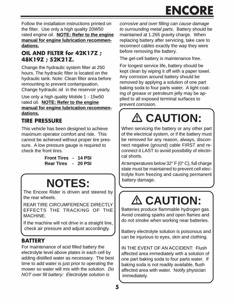
Follow the installation instructions printed onthe filter. Use only a high quality 20W50rated engine oil. NOTE: Refer to the enginemanual for engine lubrication recommen-dations.OIL AND FILTER for 42K17Z ;48K19Z ; 52K21Z.Change the hydraulic system filter at 250hours. The hydraulic filter is located on thehydraulic tank. Note: Clean filter area beforeremounting to prevent contampuation.Change hydraulic oil in the reservoir yearly.Use only a high quality Mobile 1 - 15w50rated oil. NOTE: Refer to the enginemanual for engine lubrication recommen-dations.TIRE PRESSUREThis vehicle has been designed to achievemaximum operator comfort and ride. Thiscannot be achieved without proper tire pres-sure. A low pressure gauge is required tocheck the front tires.
Front Tires - 14 PSIRear Tires - 20 PSI
BATTERYFor maintenance of acid filled battery theelectrolyte level above plates in each cell byadding distilled water as necessary. The besttime to add water is just prior to operating themower so water will mix with the solution. DoNOT over fill battery: Electrolyte solution is
NOTES:The Encore Rider is driven and steered bythe rear wheels.REAR TIRE CIRCUMFERENCE DIRECTLYEFFECTS THE TRACKING OF THEMACHINE.If the machine will not drive in a straight line,check air pressure and adjust accordingly.
� CAUTION:When servicing the battery or any other partof the electrical system, or if the battery mustbe removed for any reason, always, discon-nect negative (ground) cable FIRST and re-connect it LAST to avoid possibility of electri-cal shorts.At temperatures below 32° F (0° C), full chargestate must be maintained to prevent cell elec-trolyte from freezing and causing permanentbattery damage.
� CAUTION:Batteries produce flammable hydrogen gas.Avoid creating sparks and open flames anddo not smoke when working near batteries.
Battery electrolyte solution is poisonous andcan be injurious to eyes, skin and clothing.
IN THE EVENT OF AN ACCIDENT: Flushaffected area immediately with a solution ofone part baking soda to four parts water. Ifbaking soda is not readily available, flushaffected area with water. Notify physicianimmediately.
corrosive and over filling can cause damageto surrounding metal parts. Battery should bemaintained at 1.265 gravity charge. Whenreplacing battery after servicing, take care toreconnect cables exactly the way they werebefore removing the battery.The gel-cell battery is maintenance free.For longest service life, battery should bekept clean by wiping it off with a paper towel.Any corrosion around battery should beremoved by applying a solution of one partbaking soda to four parts water. A light coat-ing of grease or petroleum jelly may be ap-plied to all exposed terminal surfaces toprevent corrosion.

ENCORE
6
BELT ADJUSTMENTRemove key from the ignition switch. Thedeck drive belt, which may be accessed byremoving the deck plate, (see fig.1) has aturnbuckle assembly to adjust spring tension.
Spring tension should be maintained at 4" ofspring stretch measuring the spring coils. Byturning the turnbuckle clockwise it will in-crease tension, counter-clockwise will de-crease tension.When installing a belt refer to fig. 2 as to theroute of the belt.
� CAUTION:DO NOT over grease housings – it will pushseals out of bearings.
BELT TENSION TURNBUCKLE
Fig. 1 - Turnbuckle Location
TENSIONIDLER
BLADE
IDLER
ENGINEPULLEY
Fig. 2 - Mower Deck Bel t Layout
LUBRICATION for 42B350Z ;42K450Z ; 48B450Z ; 48K550Z ;52B550Z ; 52K650Z.The following recommendations on lubrica-tion should be adhered to. Environmentalconditions may be cause to vary frequency.Before each use:
Clean engine chaff screenCheck engine oil and tire
Every 100 hours:Lubricate chassisLubricate front wheelLubricate drive and pump control pivotpointsCheck belt tension
Every 200 hours:Lubricate cutter housings(1 to 2 pumps)
LUBRICATION for 42K17Z ;48K19Z ; 52K21Z.There are 5 grease points on the Z42, 48 and52. One on each caster, one on the casterswivel and one on the foot pedal pivot. Theseare all pre-greased from the factory. Environ-mental conditions may be cause to varyfrequency.Before each use:
Clean engine chaff screenCheck engine oil and tire pressure
Every 40 hours:Lubricate Casters (3 Pumps)Lubricate Deck Height Foot-Pivot(1 Pump)
Every 100 hours:Lubricate Caster Swivels (3 Pumps)Lubricate drive and pump control pivotpointsCheck belt tension

ENCORE
7
NEUTRAL ADJUSTMENT - DRIVE1. Raise the rear wheels of the rider off of theground. Safely block the frame in this posi-tion so it is secure.2. With the operator in the seat, start and runthe engine, leaving the control levers in theneutral position. Release the park brake.Check the rear wheels for neutral creep (anyrotation).3. Stop engine, place park lever into parkposition, flip up seat, and loosen jam nut onadjustable pump link (fig. 3) on the same sideas the wheel that creeps (rotates). With a 5/32" Hex Allen Wrench, adjust pump link fromthe top. For a wheel that is rotating forwardturn the wrench clockwise – for a wheel thatrotates in reverse motion turn wrenchcounter-clockwise. Never adjust link morethan 2 full turns at any one time. Retightenjam nut and start engine.4. If wheel still creeps repeat procedure instep 3.5. After final adjustment is made (make surethat the jam nut is secure on pump link), takeunit for a test drive to check tracking.
TRACKING for42B350Z ; 42K450Z ; 48B450Z ;48K550Z ; 52B550Z ; 52K650Z.
1. Return the wheels to the ground and drivethe mower to check tracking at low and fullspeed.2. If the pumps are properly neutralized,intermediate speed tracking is only affectedby tire size and/or tire pressure.3. Full speed tracking is determined by thestop bolts at the bottom of each vertical pumplink (see fig. 3). You may speed up or slowdown a fast or slow pump motor by eithershortening or lengthening the stop bolt.
TRACKING for42K17Z ; 48K19Z ; 52K21Z.To adjust the tracking there is a stop boltlocated on the bottom side of the steeringcontrol. (See Fig. 4)To adjust tracking simply loosen the lock nuton the stop bolt and turn bolt clockwise toincrease speed or counter clockwise to de-crease speed.
DRIVE ADJUSTMENTSSteering and motion controls should beuniform in all forward and reverse speeds.Levers should automatically return to neutralwhen released.
5/32 HEX
ADJUSTABLE PUMP LINK
JAM NUT
VERTICAL PUMP LINK
STOP BOLT
Fig. 3 - Neutral link area of pump

ENCORE
8
To test drive operations:Check air pressure in tires. Equal tirepressure is critical for proper driveopeation.Check linkage for excessive play.• Raise rear of Rider until rear wheels
are off the ground. Safely block theframe in this position.
• Put control levers in neutral lockposition (control levers swungoutward).
• Start engine.Wheels should not rotate. If one or both rearwheels are turning, perform procedures under“Neutral Adjustments” for side(s) that wheelturns (fig. 3).
DECK HEIGHT ADJUSTMENT for42B350Z ; 42K450Z ; 48B450Z ;48K550Z ; 52B550Z ; 52K650Z.The cutting height can be adjusted from 2 to5 inches in approximately 1/4 inch incre-ments. The height may be selected by simplymoving the deck height adjustment lever todesired cutting height.
� CAUTION:TURN OFF ENGINE BEFORE MAKING ANYADJUSTMENTS.
2 to 2 1/2 inches
each notch approx. = 1/4"
4 to 4 1/2 inches
RAISE
LOWER
DECK HEIGHT ADJUSTMENT LEVER
DECK HEIGHT ADJUSTMENT for42K17Z ; 48K19Z ; 52K21Z.
Mower heights can be adjusted by pushingthe foot pedal and by depressing the height ofcut pin and removing it. Select cutting heightand set pin accordingly.
BLOCK OF WOOD
FIG. 5
BLADESWhen removing blades, block front end up orrun front wheels onto ramps. Stop engine,remove key from the ignition switch, andapply park brake. To remove, simply holdblade bolt on bottom of the cutter housing(See Fig. 5) and turn nut counter-clockwise.Reverse procedure to reinstall. Blade boltsshould be torqued to 110 - 120 ft.lbs.Note: Deck spring washer should always becup side up or cup side to blade to insureproper torque on the blades.
ENCORE
9
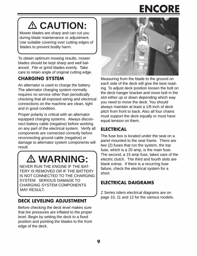
� WARNING:NEVER RUN THE ENGINE IF THE BAT-TERY IS REMOVED OR IF THE BATTERYIS NOT CONNECTED TO THE CHARGINGSYSTEM. SERIOUS DAMAGE TOCHARGING SYSTEM COMPONENTSMAY RESULT.
DECK LEVELING ADJUSTMENTBefore checking the deck level makes surethat tire pressures are inflated to the properlevel. Begin by setting the deck to a fixedposition and pointing the blades to the frontedge of the deck.
ELECTRICALThe fuse box is located under the seat on apanel mounted to the seat frame. There aretwo (2) fuses that run the system, the topfuse, which is a 20 amp, is the main fuse.The second, a 15 amp fuse, takes care of theelectric clutch. The third and fourth slots areblank extras. If there is a recurring fusefailure, check the electrical system for ashort.
ELECTRICAL DAIGRAMS
Z Series riders electrical diagrams are onpage 10, 11 and 12 for the various models.
� CAUTION:Mower blades are sharp and can cut youduring blade maintenance or adjustment.Use suitable covering over cutting edges ofblades to prevent bodily harm.
To obtain optimum mowing results, mowerblades should be kept sharp and well bal-anced. File or grind blades evenly. Takecare to retain angle of original cutting edge.
CHARGING SYSTEMAn alternator is used to charge the battery.The alternator charging system normallyrequires no service other than periodicallychecking that all exposed wiring and electricalconnections on the machine are clean, tightand in good condition.Proper polarity is critical with an alternatorequipped charging systems. Always discon-nect battery cable (negative) before workingon any part of the electrical system. Verify allcomponents are connected correctly beforereconnecting ground cable (negative) ordamage to alternator system components willresult.
Measuring from the blade to the ground oneach side of the deck will give the best read-ing. To adjust deck position loosen the bolt onthe deck hanger bracket and move bolt in theslot either up or down depending which wayyou need to move the deck. You shouldalways maintain at least a 1/8 inch of deckpitch from front to back. Also all four chainsmust support the deck equally or must haveequal tension on them.

ENCORE
10
42B
350Z
, 48
B45
0Z ,
52B
550Z
4230
78 W
IRE
HA
RN
ES
SE
LEC
TRIC
AL
DR
AW
ING
GR
OU
ND
TO
EN
GIN
E
TO B
ATT
. GR
OU
ND
TO B
ATT
. PO
S.
BLACK 18 GA.
BLA
CK
14
GA
.
RE
D /B
LAC
K S
TP. 1
8 G
A.
YE
LLO
W 1
6 G
A.
YE
LLO
W 1
6 G
A.
RED 14 GA.
GREEN 18 GA.
GR
EE
N 1
8 G
A.
GR
EE
N 1
8 G
A.
PURPLE 18 GA.
ORANGE 18 GA.
DK
. BLU
E 1
8 G
A.
WHITE 16 GA.
FUS
E
BLO
CK
IGN
ITIO
N S
WIT
CH
NE
UTR
AL
SW
ITC
HC
LUTC
H
SW
ITC
H
SE
AT
SW
ITC
H
EN
GIN
E K
ILL
BLACK 16 GA.
BLA
CK
16
GA
.
BROWN 18 GA.
BROWN 18 GA.
BLACK / WHITE 18 GA.
DK. BLUE 18 GA.
LT. BLUE 14 GA.
LT. BLUE 14 GA.
LT. B
LUE
14
GA
.
RED 12 GA.
RE
D 1
2 G
A.
EN
GIN
E F
UE
L S
OLE
NO
ID
EN
GIN
E
CH
AR
GIN
G
OR
AN
GE
12
GA
.
WIR
E J
UN
CTI
ON
HO
UR
ME
TER
MO
DU
LE
CO
NN
.
PA
RK
BR
AK
E
SW
ITC
H
CLU
TCH
C
ON
N.
STA
RTE
R R
ELA
Y
RE
D /B
LAC
K S
TP. 1
8 G
A.

ENCORE
11
STA
RTE
R
RE
LAY
15 A
MP
FU
SE
20 A
MP
FU
SE
RED 14 GA.
LT. BLUE 14 GA.
BROWN 18 GA.
BLACK 16 GA.
GREEN 18 GA.
PA
RK
BR
AK
E
SW
ITC
H
WIR
E
JUN
CTI
ON
RE
D 1
2 G
A.
BLACK / WHITE 18 GA.
DK
. BLU
E 1
8 G
A.
EN
GIN
E K
ILL
RE
D /B
LAC
K S
TP. 1
8 G
A.
TO B
ATT
. PO
S.
ORANGE 18 GA.
EN
GIN
E
CH
AR
GIN
GE
NG
INE
FU
EL
SO
LEN
OID
TO B
ATT
. GR
OU
NDB
LAC
K 1
6 G
A.
42K
450Z
, 48
K55
0Z ,
52K
650Z
4232
37 W
IRE
HA
RN
ES
SE
LEC
TRIC
AL
DR
AW
ING
RE
D /B
LAC
K S
TP. 1
8 G
A.
IGN
ITIO
N S
WIT
CH
FUS
E
BLO
CK
WHITE 16 GA.
RED 12 GA.
LT. BLUE 14 GA.
OR
AN
GE
12
GA
.
YE
LLO
W 1
6 G
A.
YE
LLO
W 1
6 G
A.
BLA
CK
14
GA
.
BLACK 18 GA.
CLU
TCH
C
ON
N.
GR
OU
ND
TO
EN
GIN
E
CLU
TCH
S
WIT
CH
NE
UTR
AL
SW
ITC
H
GR
EE
N 1
8 G
A.
LT. B
LUE
14
GA
.
BROWN 18 GA.
MO
DU
LE
CO
NN
.
SE
AT
SW
ITC
H PURPLE 18 GA.
GR
EE
N 1
8 G
A.
DK. BLUE 18 GA.
HO
UR
ME
TER

ENCORE
12
RED 14 GA.
STA
RTE
R
RE
LAY
BLACK 16 GA.
BROWN 18 GA.
LT. BLUE 14 GA.
PA
RK
BR
AK
E
SW
ITC
H
RE
D 1
2 G
A.
EN
GIN
E F
UE
L S
OLE
NO
ID
EN
GIN
E
CH
AR
GIN
G
ORANGE 18 GA.
TO B
ATT
. PO
S.
RE
D /B
LAC
K S
TP. 1
8 G
A.
EN
GIN
E K
ILL
DK
. BLU
E 1
8 G
A.
BLA
CK
16
GA
.
TO B
ATT
. GR
OU
ND
20 A
MP
FU
SE
15 A
MP
FU
SE
WIR
E J
UN
CTI
ON
42K
17Z
, 48K
19Z
, 52K
21Z
4233
51 W
IRE
HA
RN
ES
SE
LEC
TRIC
AL
DR
AW
ING
OR
AN
GE
12
GA
.
LT. BLUE 14 GA.
RED 12 GA.
WHITE 16 GA.
FUS
E
BLO
CK
IGN
ITIO
N
SW
ITC
H
RE
D /B
LAC
K S
TP. 1
8 G
A.
YE
LLO
W 1
6 G
A.
YE
LLO
W 1
6 G
A.
GREEN 18 GA.
GR
OU
ND
TO
EN
GIN
E
NE
UTR
AL
SW
ITC
H
CLU
TCH
C
ON
N.
BLACK 18 GA.
BLA
CK
14
GA
.
BLACK / WHITE 18 GA.
MO
DU
LE
CO
NN
.
BROWN 18 GA.
LT. B
LUE
14
GA
.
GR
EE
N 1
8 G
A.
CLU
TCH
S
WIT
CH
HO
UR
ME
TER
DK. BLUE 18 GA.
GR
EE
N 1
8 G
A. PURPLE 18 GA.
SE
AT
SW
ITC
H

ENCORE
13
BDP-10L VARIABLE PUMP – SUPPORT SYSTEMTRANSMISSION HYDRAULIC SUPPORT SYSTEM
The charge pump incorporated into the BDP-10L units supplies fluid to keep the closedloop charged, preventing cavitations andproviding cooling oil flow for the system. Aninlet filter is required to insure that only cleanfluid enters the system. The charge reliefvalve is designed to maintain the chargepressure at 25 to 70 PSI at 3600 RPM inputspeed.
Since either of the main hydraulic passagescan be at high pressure, two (2) charge checkvalves are used to direct make-up fluid intothe low-pressure side of the closed loop.These check valves are located in the pumpend cap.
FILTER
RESERVOIR
CASEDRAIN
INPUTSHAFT
VARIABLESWASHPLATE
CYLINDERBLOCKASSEMBLY
VARIABLEDISPLACEMENT
PUMPCOOLINGORIFICE
CHARGEPUMP
BYPASSVALVE
CHARGERELIEFVALVE
CHECKVALVE
LINE B
LINE A
CHECKVALVE
� CAUTION:The loss of hydrostatic driveline power in
any mode of operation may cause a loss ofhydrostatic braking capacity. A braking system,redundant to the hydrostatic transmission must,therefore, be provided which is adequate to stopand/or hold the system should the conditiondevelop.
Certain service procedures may require thevehicle/machine to be disabled (wheels raisedoff the ground, work function disconnect, etc.)while performing them in order to prevent injury
to the technician and bystanders.
� CAUTION:Use caution when dealing with hydraulic
fluid under pressure. Escaping hydraulic fluidunder pressure can have sufficient force topenetrate your skin causing serious injury. Thisfluid may also be hot enough to burn. Seriousinfection or reactions can develop if propermedical treatment is not administeredimmediately.
Some cleaning solvents are flammable. Toavoid possible fire, do not use cleaning solventsin an area where a source of ignition may bepresent.
ENCORE
14
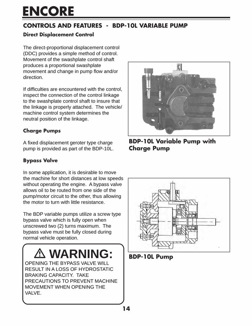
CONTROLS AND FEATURES - BDP-10L VARIABLE PUMPDirect Displacement Control
The direct-proportional displacement control(DDC) provides a simple method of control.Movement of the swashplate control shaftproduces a proportional swashplatemovement and change in pump flow and/ordirection.
If difficulties are encountered with the control,inspect the connection of the control linkageto the swashplate control shaft to insure thatthe linkage is properly attached. The vehicle/machine control system determines theneutral position of the linkage.
Charge Pumps
A fixed displacement geroter type chargepump is provided as part of the BDP-10L.
Bypass Valve
In some application, it is desirable to movethe machine for short distances at low speedswithout operating the engine. A bypass valveallows oil to be routed from one side of thepump/motor circuit to the other, thus allowingthe motor to turn with little resistance.
The BDP variable pumps utilize a screw typebypass valve which is fully open whenunscrewed two (2) turns maximum. Thebypass valve must be fully closed duringnormal vehicle operation.
� WARNING:OPENING THE BYPASS VALVE WILLRESULT IN A LOSS OF HYDROSTATICBRAKING CAPACITY. TAKEPRECAUTIONS TO PREVENT MACHINEMOVEMENT WHEN OPENING THEVALVE.
BDP-10L Variable Pump withCharge Pump
BDP-10L Pump

ENCORE
15
START UP MAINTENACE - BDP-10L VARIABLE PUMP
Fluids
Fluids used with Hydro-Gear product shouldbe carefully selected with assistance from areputable supplier.
Typically, an API classification SG/CD engineoil is used with a viscosity range equivalent to20W50.
Start-up Procedure
The following start-up procedure shouldalways be followed when starting a newinstallation or when restarting an installationin which the BDP has been removed from thesystem.
� WARNING:THE FOLLOWING PROCEDURE MAYREQUIRE THE VEHICLE/MACHINE TO BEDISABLED (WHEELS RAISED OFF THEGROUND, WORK FUNCTIONDISCONNECTED, ETC.) WHILEPERFORMING THE PROCEDURE INORDER TO PREVENT INJURY TO THETECHNICIAN AND BYSTANDERS.
Prior to staring the BDP, make certain allsystem components (reservoir, fittings, etc.)are clean prior to filling with fluid.
Be certain to fill the BDP housing withclean fluid prior to start-up. Fill the housingby pouring filtered oil into the upper casedrain port, if possible.
Fill the reservoir with recommended fluidwhich should be filtered prior to entering thereservoir.
The inlet line and filter leading from thereservoir to the charge pump must be filled
prior to start-up. Check inlet line for properlytightened fittings and make sure it is free ofrestrictions and air leaks.
Pressurizing the inlet 2-4 PSI will aid in start-up. “Jog” or slowly rotate the engine with theswashplate in its neutral (0 angle) positionuntil charge pressure starts to rise (chargepressure is defined as low side looppressure).
� WARNING:DO NOT START ENGINE UNLESS THEPUMP IS IN THE NEUTRAL POSITION(0 SWASHPLATE ANGLE) OR THE DRIVEWHEELS ARE OFF THE GROUND.
Start the engine and run at the lowestpossible RPM.
With the bypass valve closed, slowly movethe displacement control in both the forwardand reverse directions. As air is purged fromthe unit, the oil level in the reservoir will dropand bubbles may appear in the fluid. Refillthe reservoir as necessary.
Place the displacement control in the neutralposition and open the bypass valve. Slowlymove the displacement control in both theforward and reverse directions to purge theair from the closed circuit.
Close the bypass valve and run the unit inboth directions for several minutes until anyremaining air is purged from the unit. Refillthe reservoir as necessary.
Shut down the engine, check for and correctany fluid leaks, and check the reservoir level.Add fluid if necessary. The transmission isnow ready for operation.

ENCORE
16
Maintenance
Check the reservoir daily for proper fluidlevel, the presence of water (noted by acloudy to milky appearance, or free water inbottom of reservoir), and rancid fluid odor(indicating excessive heat).
The BDP-10L units normally do not requireregular fluid changes. The system filtershould be changed per the vehicle/machinemanufacturer’s recommendations. The fluidand filter should be changed and the systemcleaned if the fluid becomes contaminatedwith foreign matter (water, dirt, grease, etc.)or if the fluid has been subjected totemperature levels greater than the maximumrecommended.

Notes:

ENCORE WARRANTYFor Prowler and Z Series Mowers(excluding the Z 34)This warranty extends to the original retail purchaser only and commences on the date oforiginal retail purchase. Any part of the Encore commercial mower manufactured byEncore Mfg. Co., Inc. and found in reasonable judgment of Encore Mfg. Co., Inc. to bedefective in material or workmanship will be repaired or replaced by an Authorized EncoreDealer without charge for parts and labor. The Encore mower including any defective partmust be returned to an Authorized Encore Service Dealer within the warranty period. Theexpense of delivering the mower to the dealer for warranty work and the expense ofreturning it back to the owner after repair or replacement will be paid by the owner. Thiswarranty is limited to two year for frame, deck, hydrostatic drive system (excluding hoses),gear-box and drive shaft. The warranty will be first year parts and labor, second yearparts only, from the date of purchase, against defects in workmanship and material (90days for rental use) for any Encore Rider that is used for commercial or any other incomeproducing purpose. Cutter housings will carry a 2 year warranty parts and labor. Belts andtires are warranted for 90 days against defects in materials and workmanship.Cutter housings, electrical components, hydraulic components and electric-clutch must bereturned before warranty will be paid.The engine is covered by its respective manufacturer please refer to the manufacture’swarranty statement that is included in the literature packet. Engine warranties should bereferred to the nearest authorized service outlet of the engine manufacturer.The responsibility of Encore Mfg. Co., Inc. in respect to claim is limited to making therequired repairs or replacements, and no claim of breach of warranty shall be cause forcancellation or recession of the contract of sale of any Encore mower.Proof of purchase is required by both Encore and the servicing Dealer, before anywarranty will be paid, and warranty work must be preformed by an Authorized Encoreservice dealer.This warranty does not cover any Encore mower that has been altered or modified so asto adversely affect the intended use of the product, it operation, performance, or durability.This warranty also does not cover any mower that has been subject to misuse, neglect,negligence, accident or that has been operated in any way contrary to the operatinginstructions as specified in the Operators Manual.Encore Mfg. Co., Inc. reserves the right to change or improve the design of any mowerwithout assuming any obligation to modify any mower previously manufactured.Encore Mfg. Co., Inc. obligation under warranty is strictly and excessively limited to repairor replacement of defective parts. Encore Mfg. Co., Inc. does not assume or authorizeanyone to assume for them any other obligation.ENCORE MFG. CO., INC. CANNOT BE RESPONSIBLE FOR THE WAY YOU OPERATE,OR THE CONDITIONS IN WHICH YOU OPERATE THE MOWER. USE COMMONSENSE AT ALL TIMES.As of September 1, 2002 this warranty statement supersedes any warranty statementpublished by ENCORE MANUFACTURING CO., INC.

,ENCORE MANUFACTURING CO., INC.All rights reserved. Contents subject to change. Part Number
1102 AZ SERIES
42B350Z - OPERATORS MANUAL933077