Embed Size (px)
Citation preview

Specification for Unbonded Single-Strand Tendons and Commentary
ACI 423.6-01/423.6R-01
Reported by ACI Committee 423
Sarah L. Billington Pawan R. Gupta Julio A. Ramirez
Kenneth B. Bondy* J. Weston Hall David M. Rogowsky
Ned H. Burns† Mohammad Iqbal Bruce W. Russell
Gregory P. Chacos Francis J. Jacques David H. Sanders
Todd J. Christopherson L. S. Paul Johal Thomas C. Schaeffer
Steven R. Close† Susan N. Lane Andrea J. Schokker
Henry J. Cronin, Jr. Leslie D. Martin Morris Schupack†
Charles W. Dolan Gerard J. McGuire† Kenneth W. Shushkewich
Apostolos Fafitis Mark Edward Moore Richard W. Stone
Martin J. Fradua Antoine E. Naaman H. Carl Walker†
Catherine E. French Thomas E. Nehil Paul Zia†
William L. Gamble Denis Chuen Pu
*Chair of subcommittee that prepared this specification.†Member of subcommittee that prepared this specification.
Ward N. MarianosChairman
Shawn P. GrossSecretary
ACI Committee Reports, Guides, Standard Practices,and Commentaries are intended for guidance in planning,designing, executing, and inspecting construction. TheCommentary is intended for the use of individuals who arecompetent to evaluate the significance and limitations ofits content and recommendations and who will accept re-sponsibility for the application of the material it contains.The American Concrete Institute disclaims any and all re-sponsibility for the stated principles. The Institute shallnot be liable for any loss or damage arising therefrom.
Reference to the Commentary shall not be made in con-tract documents. If items found in this document are de-sired by the Architect/Engineer to be a part of the contractdocuments, they shall be restated in mandatory languagefor incorporation by the Architect/Engineer.
This specification provides specific performance criteria for materials forunbonded single strand tendons and detailed recommendations for fabrica-tion and installation of unbonded single strand tendons. Specifications arepresented for tendons in non-aggressive environments and for tendons inaggressive environments. The more restrictive material, fabrication, andconstruction requirements for tendons used in aggressive environments areessential to the long-term durability of tendons used in such circumstances.
Notes to Specifier: This specification is incorporated by reference in theproject specifications using the wording in P4 of the preface and includingthe information from the mandatory, optional, and submittal checklistsfollowing the specification.
ACI Specification 423.6-01 and Commentary 423.6R-01 are pre-sented in a side-by-side column format, with specification text placed inthe left-hand column and the corresponding commentary text aligned inthe right column. Commentary section numbers are preceded by the let-ter “R.” The Commentary is not a part of this specification.
423.6/4
ACI 423.6-01/423.6R-01 became effective October 31, 2001.Copyright 2001, American Concrete Institute.All rights reserved including rights of reproduction and use in any form or by any
means, including the making of copies by any photo process, or by electronic ormechanical device, printed, written, or oral, or recording for sound or visual reproduc-tion or for use in any knowledge or retrieval system or device, unless permission inwriting is obtained from the copyright proprietors.
Keywords: anchorage; construction joint; contractor; coupler; deicer; post-tensioning; prestress; prestressing steel; sheathing; specification; strand;unbonded tendon.
CONTENTSPreface, p. 423.6/423.6R-2
Part 1—General, p.423.6/423.6R-31.1—Scope1.2—Definitions1.3—Referenced standards1.4—System description1.5—Submittals
1.5.1—Prestressing steel1.5.2—Anchorages and couplers1.5.3—Sheathing1.5.4—Post-tensioning coating1.5.5—Fabrication plant1.5.6—Stressing jack calibration1.5.7—Stressing records
1.6—Fabrication1.6.1—General1.6.2—Handling, storage, and shipping
1.6.2.1—Handling1.6.2.2—Storage before shipping1.6.2.3—Shipping
1.7—Delivery, handling, and storage
23.6R-1

423.6/423.6R-2 ACI STANDARD AND COMMENTARY
1.7.1—Delivery1.7.2—Handling and storage
Part 2—Products, p. 423.6/423.6R-112.1—Prestressing steel
2.1.1—General2.1.2—Acceptance criteria for surface condition2.1.3—Compliance requirements
2.2—Anchorages and couplers2.2.1—Anchorages2.2.1.1—Static tests2.2.1.2—Fatigue tests2.2.1.3—Bearing stresses2.2.2—Castings2.2.3—Wedge-type anchorages2.2.4—Couplers2.2.5—Compliance requirements2.2.6—Anchorages and couplers in aggressive
environments2.3—Sheathing
2.3.1—General properties2.3.2—Minimum thickness and diameter2.3.3—Manufacturing processes2.3.4—Sheathing coverage2.3.5—Aggressive environments
2.4—Post-tensioning coating2.4.1—General properties2.4.2—Type of coating2.4.3—Minimum quantity2.4.4—Performance criteria
Part 3—Execution, p. 423.6/423.6R-223.1—General3.2—Tendon installation
3.2.1—General3.2.2—Stressing-end anchorages3.2.3—Intermediate anchorages3.2.4—Fixed-end anchorages
3.2.4.1—Wedge-type anchorages3.2.5—Sheathing inspection and repair
3.3—Concrete placement
3.3.1—General3.3.2—Placement3.3.3—Protection of tendons3.3.4—Sheathing repair
3.4—Tendon stressing3.4.1—General3.4.2—Jack calibration3.4.3—Elongation measurement
3.5—Tendon finishing3.5.1—General3.5.2—Aggressive environments3.5.3—Stressing pockets
Forward to checklists, p.423.6/423.6R-28
Mandatory checklist, p. 423.6/423.6R-28
Optional checklist, p. 423.6/423.6R-28
PREFACE TO ACI SPECIFICATION 423P1. ACI Specification 423 is intended to be used by refer-
ence or incorporation in its entirety in the project specifica-tions. Do not copy individual sections, articles, orparagraphs into the project specifications, because takingthem out of context may change their meaning.
P2. If sections or parts of ACI Specification 423 are cop-ied into project specifications or any other document, do notrefer to them as an ACI Specification, because the specifica-tion has been altered.
P3. Each technical section of ACI Specification 423 iswritten in the three-part section format of the ConstructionSpecifications Institute, as adapted for ACI requirements.The language is imperative and terse.
P4. A statement such as the following will serve to makeACI Specification 423 a part of the project specifications:
Work on (Project Title) shall conform to all requirementsof ACI (Specification number with date suffix and title) pub-lished by the American Concrete Institute, Farmington Hills,Michigan, except as modified by these contract documents.
P5. Units — The values stated in inch-pound units are tobe regarded as the standard. The values in SI units givenin parentheses are for information only.

SPECIFICATION COMMENTARY
SPECIFICATION FOR UNBONDED SINGLE-STRAND TENDONS AND COMMENTARY 423.6/423.6R-3
PART 1 — GENERAL
1.1 — Scope
This specification provides specific performance criteriafor materials for unbonded single strand tendonsand detailed recommendations for fabrication andinstallation of unbonded single strand tendons.Specifications are presented for tendons in non-aggressive environments and for tendons in aggressiveenvironments.
The more restrictive material, fabrication, and con-struction requirements for tendons used in aggressiveenvironments are essential to the long-term durabilityof tendons used in such circumstances.
R1.1 — Scope
The intent of this document is to provide detailed specifica-tions for all common structural uses of unbonded post-tensioning tendons. It is not intended to apply to tendonsused in ground-supported post-tensioned slabs for lightresidential construction. There are certain special structuresor applications that either because of their service requirementsor structural behavior might impose additional requirementson the post-tensioning system that exceed the minimumrequirements of this specification. In such cases, a specialspecification should be developed.
Structures exposed to aggressive environments include allstructures subjected to direct or indirect applications ofdeicing chemicals, seawater, brackish water, or spray fromthese sources; structures in the immediate vicinity of sea-coasts exposed to salt-laden air; and structures whereanchorage areas are in direct contact with soil. Stressingpockets that are not maintained in a normally dry conditionafter construction should also be considered exposed to anaggressive environment. Nearly all enclosed buildings(office buildings, apartment buildings, warehouses, manu-facturing facilities) are considered to be non-aggressiveenvironments. The engineer should decide if the structure,or a part of the structure, is exposed to an aggressiveenvironment. Attention should be paid to such areas asthe location of stressing-end and intermediate anchors,construction joints, locations of planters, balconies andswimming pools.
The durability of prestressed structures in aggressiveenvironments requires the use of consistently higherquality concrete, and superior construction practices thanrequired in non-aggressive environments.
This specification is not intended to apply to nonstructuralapplications, which might include topping slabs, water-proofing slabs on fill, and post-tensioning used only for controlof cracking or deflection. For nonflexural or membrane typestructures primarily under tensile forces, the provisions,where appropriate, are intended to apply.
This specification should be considered a minimum stan-dard and, due to experience or project considerations, maybe made more restrictive by the engineer.

SPECIFICATION COMMENTARY
423.6/423.6R-4 ACI STANDARD AND COMMENTARY
1.2 — Definitions
Aggressive environment — An environment inwhich structures are exposed to direct or indirect appli-cations of deicing chemicals, seawater, brackish water,or spray from these water sources; and salt-laden airas occurs in the vicinity of seacoasts. Aggressive envi-ronments also include structures where stressingpockets are wetted or are directly in contact with soils.
Anchorage — A mechanical device comprising allcomponents required to anchor the prestressing steeland permanently transmit prestressing force to concrete.
Concrete contractor — Contracting entity respon-sible for placing, finishing, and curing the post-tensionedconcrete.
Coupler — A device designed to connect ends oftwo strands together, thereby transferring the pre-stressing force from end to end of the tendon.
Encapsulated tendon — A tendon that is com-pletely enclosed in a watertight covering from end toend, including a protective cap over the tendon tail ateach end.
Engineer — Design professional responsible forthe structural design of the post-tensioned concretemembers on the project.
Non-aggressive environment — All environmentsnot specifically defined herein as aggressive, includingenclosed buildings.
Prestressing steel — High-strength steel used toprestress concrete, most commonly 7-wire strand. It isthe element of a post-tensioning tendon that is elon-gated and anchored to provide the necessary designprestressing force.
Post-tensioning coating — Material used to protectagainst corrosion and reduce friction between pre-stressing steel and sheathing.
Post-tensioning installer — Contracting entity respon-sible for unloading the post-tensioning materials, storingand protecting them on the job site at all stages ofhandling, storage, placement, tendon installation,stressing, and tendon finishing in accordance withthe contract documents and this specification.
Post-tensioning supplier — Contracting entityresponsible for providing all components of the post-tensioning system including the tendons, anchorages,couplers, field placement drawings, and stressingequipment, and delivering them to the job site.

SPECIFICATION COMMENTARY
SPECIFICATION FOR UNBONDED SINGLE-STRAND TENDONS AND COMMENTARY 423.6/423.6R-5
Sheathing — A material forming an enclosure inwhich prestressing steel is encased to prevent bondingwith surrounding concrete, to provide corrosion protec-tion, and to contain post-tensioning coating.
Tendon — A complete assembly consisting ofanchorages, prestressing steel, post-tensioning coatingand sheathing. The tendon imparts prestressing forcesto concrete.
Unbonded tendon — Tendon in which prestressingsteel is prevented from bonding to concrete, and isfree to move relative to concrete. Prestressing force istransferred to concrete by anchorages only.
1.3 — Referenced standards
ASTMA370-97a Standard Test Methods and Definitions
for Mechanical Testing of Steel Products
A 416/ Standard Specification for Steel Strand,416M-99 Uncoated Seven-Wire for Prestressed
Concrete
B 117-97 Standard Practice for Operating Salt Spray(Fog) Apparatus
C 1077-00 Standard Practice for Laboratories TestingConcrete and Concrete Aggregates for Usein Construction and Criteria for LaboratoryEvaluation
D 92-98a Standard Test Method for Flash and FirePoints by Cleveland Open Cup
D 95-99 Standard Test Method for Water in Petro-leum Products and Bituminous Materials byDistillation
D 512-89 Standard Test Methods for Chloride Ion in(1999) Water
D 566-97 Standard Test Method for Dropping Point ofLubricating Grease
D 610-95 Standard Test Method for Evaluating Degreeof Rusting on Painted Steel Surfaces
D 638-00 Standard Test Method for Tensile Propertiesof Plastics
D 792-00 Standard Test Methods for Density andSpecific Gravity (Relative Density) of Plasticsby Displacement
R1.3 — Cited references
1. Mattock, A. H.; Yamazaki, J.; and Kattula, B. T., “Com-parative Study of Prestressed Concrete Beams, with andwithout Bond,” ACI JOURNAL, Proceedings, V. 68, No. 2,Feb., 1971, pp. 116-125.
2. Society of Automotive Engineers, “SAE-J449 SurfaceTexture Control (1963),” 400 Commonwealth Drive,Warrendale, PA.

SPECIFICATION COMMENTARY
423.6/423.6R-6 ACI STANDARD AND COMMENTARY
D 2265-00 Standard Test Method for Dropping Point ofLubricating Grease Over Wide TemperatureRange
D 3867-99 Standard Test Methods for Nitrite-Nitrate inWater
D 4289-97 Standard Test Method for Elastomer Com-patibility of Lubricating Greases and Fluids
E 328-86 Standard Test Methods for Stress Relax-ation Tests for Materials and Structures
American Public Health AssociationAPHA 4500-S2E
Federal Test Method StandardFTMS 791 B Method 321.2
Post-Tensioning InstituteField Procedures Manual for Unbonded Single StrandTendons, October 2000.
These publications may be obtained from theseorganizations:
American Society for Testing and Materials (ASTM)100 Bar Harbour DriveWest Conshohocken, PA 19428-2957610/832-9585 FAX 610/832-9555
American Public Health Association (APHA)1015 15th Street N.W., 3rd FloorWashington, D.C., 20005202/789-5600
Federal Test Method Standard (FTMS)U.S. Army General Materiel and Parts CenterPetroleum Field Office (East)New Cumberland Army DepotNew Cumberland, PA 17070 (NCAD)
Post Tensioning Institute1717 W. Northern Avenue, Suite 114Phoenix, AZ 85021-5470602/870-7540
1.4 — System description
Unbonded single-strand post-tensioning tendons areused as prestressed reinforcement in a wide variety ofconcrete building projects, and for the strengtheningand retrofit of buildings built with all types of structuralmaterials. The tendon consists of the prestressingsteel and a post-tensioning coating encased in asheath that prevents bond with the adjacent concreteand provides additional corrosion protection. Anchor-
SPECIFICATION COMMENTARY
SPECIFICATION FOR UNBONDED SINGLE-STRAND TENDONS AND COMMENTARY 423.6/423.6R-7
ages transfer the prestressing force to the concrete atthe extreme ends of the tendon and at intermediatepoints as required. When stressing is required at eitheror both extreme ends of the tendon, the anchoragelocated at those points is called a stressing-endanchorage. When stressing is required at some pointalong the length of the tendon, between the ends, theanchorage at that point is called an intermediateanchorage. When stressing is not required at oneextreme end of the tendon, the anchorage located atthat point is called a fixed-end anchorage.
Tendons are typically fabricated in a manufacturingfacility or plant. Fabrication consists of applying post-tensioning coating and sheathing to the prestressingsteel, cutting the tendon to a specified length andmarking it for a specific location in the structure,attaching the fixed-end anchorages, positioning inter-mediate anchors, if required, coiling and securing thetendons into bundles which are loaded onto trucks fordelivery to the job site along with the stressing-endanchorages, wedges, stressing equipment, and allrequired accessories.
At the construction site, the tendons are installed intothe forms (in new construction) or externally attachedto an existing structure (in retrofits). The tendon profileand number of tendons (or effective prestress force) isspecified by the engineer. Stressing of the tendons isdone with hydraulic equipment (jacks and pumps). Innew construction, stressing is done after the concreteis placed and reaches a minimum compressivestrength, determined by the engineer. In retrofits ten-don stressing is done as soon as practical after instal-lation of tendons and required hardware. Afterstressing, the protruding ends of the tendons are cutoff, and any pockets required to recess the stressingend anchorages inside the concrete surfaces are filledwith grout and finished.
1.5 — Submittals
1.5.1 — Prestressing steel
Certified mill test reports shall be furnished for eachcoil or pack of strand, containing the following testinformation:
• Heat number and identification;• Tensile strength;• Yield stress at 1% extension under load;• Elongation at failure;
R1.5 — Submittals
R1.5.1 — Prestressing steel
It is recommended that designers verify the material proper-ties of the strand on their project to avoid the possibility ofinadvertent substitution of strand with material having lowerphysical properties, which might reduce the structuralcapacity of some members.
Although ASTM A 416/A 416M does not specify a standardchemical analysis for the heat of steel, such analysis is available.
Tensile strength is defined as the tensile stress at ultimate.

SPECIFICATION COMMENTARY
423.6/423.6R-8 ACI STANDARD AND COMMENTARY
• Modulus of elasticity;• Diameter and net area of strand; and• Type of material (normal = relaxation or low =
relaxation).
1.5.2 — Anchorages and couplers
Static and fatigue test reports of representativeassemblies shall be furnished for each differentassembly to be used on the project.
1.5.3 — Sheathing
A sheathing material report shall be furnished con-taining type, thickness, and density of material; andsupporting test data demonstrating compliance with allrequirements of Section 2.3.
1.5.4 — Post-tensioning coating
Test results on post-tensioning coating, tested inaccordance with Table 1, shall be furnished.
1.5.5 — Fabrication plant
A copy of the tendon fabrication plant certificationshall be furnished.
1.5.6 — Stressing jack calibration
Calibration certificates for every jack and gage shallbe furnished (Section 3.4.2).
1.5.7 — Stressing records
Stressing records shall be filled out during thestressing operation, with the following data recorded:
• Name of the project;• Floor number and concrete placement area number;• Tendon identification mark;• Required elongation;• Stressing jack calibration certificate (Section 1.5.6
and 3.4.2);• Gage pressure to achieve required stressing force
per supplied calibration chart;• Actual elongation achieved;• Actual gage pressure;• Date of stressing operation;• Name and signature of stressing operator or
inspector;• Serial or identification number of jacking equipment;• Date of approved installation drawings used for
installation and stressing; and
COMMENTARY
SPECIFICATION FOR UNBONDED SINGLE-STRAND TENDONS AND COMMENTARY 423.6/423.6R-9
SPECIFICATION• Weather conditions including temperature and
rainfall.
Completed stressing records shall be submitted to theengineer for acceptance.
1.6 — Fabrication
1.6.1 — General
Unbonded single-strand tendons shall be fabricated in aplant certified by an externally audited quality assuranceprogram, which shall ensure that the unbonded tendonsand components comply with the requirements of thisspecification. The post-tensioning supplier shall beresponsible for the fabrication and packaging ofunbonded tendons. Individual tendons shall be securedin bundles using a tying product that does not damagethe sheath. The tendon sheath shall be protected fromdamage by banding materials. Padding material shall beused between any metal banding and the tendon.
1.6 — Fabrication
R1.6.1 — General
The requirements of this section apply to tendons intendedfor use in both aggressive and non-aggressive environments.Plants certified by the Post-Tensioning Institute (PTI) havebeen shown to meet the fabrication requirements of thisspecification.
1.6.2 — Handling, storage, and shipping
The post-tensioning supplier shall be responsible forthe handling, storage, and shipping of unbondedtendons, including:
1.6.2.1 — Handling
1) Tendons shall not be damaged during handling,loading, or moving at supplier’s yard;
2) Smooth forklift booms or padded forks shall beused to handle tendons;
3) Slings used to lift tendons shall be non-metallic(metal chokers or chains shall not be used); and
4) All tendons shall be protected during bundling,handling, loading, and securing to transporta-tion. Tendons shall be protected from rain,snow, deicing salts, and other corrosive ele-ments during transportation.
1.6.2.2 — Storage before shipping
1) All tendons shall be protected from exposureto rain and snow;
2) Fabricated tendons shall be stored on apaved surface with proper drainage awayfrom tendons; and
3) All tendons stored for 1 month or longer shall be protected from the damaging effects of direct sunlight.
R1.6.2.2 — Storage before shipping
Protection is required to prevent water from penetratingtendons.
Means of protection from direct sunlight may be an additiveto the sheathing material and/or by external protection.

SPECIFICATION COMMENTARY
423.6/423.6R-10 ACI STANDARD AND COMMENTARY
1.6.2.3 — Shipping
1) Non-metallic tie-downs shall be used tosecure tendon bundles to trailer bed. Metalstrapping or chains shall not be used;
2) Protection shall be provided between trailerbed and bundles to protect sheathing duringtransportation; and
3) Encapsulated materials shipped into areasdefined as aggressive environments shall beprotected during transportation.
R1.6.2.3 — Shipping
It is not required that all shipments of encapsulated materialsbe shrink-wrapped. This may be determined by the engineeron each individual project. Protection of encapsulatedtendons during shipping may be done by using enclosedtrailers, covering by tarps, or by other methods specified by theengineer.
1.7 — Delivery, handling, and storage
1.7.1 — Delivery
Tendons, accessories, and equipment shall be protectedto maintain their integrity and satisfy this specification.
R1.7 — Delivery, handling, and storage
R1.7.1 — Delivery
If the engineer intends to assign responsibility for protectionof tendons, accessories, and equipment to parties other thanthe post-tensioning supplier during shipping and the post-tensioning installer after shipping, this should be stated inthe contract documents.
1.7.2 — Handling and storage
1.7.2.1 — During the unloading process, care shallbe taken not to damage sheathing or anchorages.Chains or hooks shall not be used.
R1.7.2 — Handling and storage
R1.7.2.1 — It is recommended that nylon or other non-metallic slings be used during unloading and handling oftendons. Slings should never be choked in the handling oftendon coils. Coils should be cradled in the slings bypassing them through the center of the coil.
1.7.2.2 — Tendons shall be unloaded as close aspossible to the designated storage area to avoidexcessive handling.
R1.7.2.2 — Multiple storage moves increase the possibilityof damage to sheathing and other components of the system.
1.7.2.3 — Materials and equipment shall be storedin a dry area on dunnage. Materials shall not beexposed to water, snow, deicing salts or other corrosiveelements. When long-term storage is required (morethan one month), materials shall be protected fromexposure to direct sunlight.
R1.7.2.3 — Proper job site storage of materials is criticalto the integrity of tendons. When tarps are used for protectionof the tendons, they should be maintained by the installer andconstructed in a tent-like fashion to allow the free circulationof air around the tendon bundles to avoid condensation beingtrapped under the tarps.
1.7.2.4 — Wedges and anchorages shall be identi-fied by individual concrete placement area, floorsequence, or both. Materials shall only be used in theiridentified concrete placement areas. In the event thatmaterials intended for one concrete placement areaare exchanged into another concrete placement area,the transaction shall be noted for traceability purposes.
R1.7.2.4 — Any movement of anchorages and wedgesabout the job site should be done with care to retain thetraceability of such materials.

SPECIFICATION COMMENTARY
SPECIFICATION FOR UNBONDED SINGLE-STRAND TENDONS AND COMMENTARY 423.6/423.6R-11
PART 2 — PRODUCTS
2.1 — Prestressing steel
2.1.1 — General
2.1.1.1 — Prestressing steel used in unbonded sin-gle strand post-tensioning tendons shall conform toone of the following requirements:
• ASTM A 416/A 416M• Strand not specifically identified in ASTM A 416/
A 416M shall conform to minimum requirements of this specification and have properties meeting requirements of ASTM A 416/A 416M.
R2.1 — Prestressing steel
R2.1.1 — General
R2.1.1.1 — Provision can be made for new steels, whichwould include new sizes, improved characteristics of relax-ation, or improved mechanical properties. However, use ofprestressing steels not covered by ASTM Specificationsshould be permitted only when the supplier provides testdata certified by an independent testing laboratory substan-tiating that all characteristics of the material are comparableor superior to the properties of steels conforming to theASTM Specifications. In particular, the stress corrosioncharacteristics of steels produced by quench and temperheat treatments and steels with specified minimum tensilestrengths over 270 ksi (1860 MPa) should be evaluated care-fully. Relaxation properties of new steels should be basedon a minimum test period of 1000 h.
2.1.1.2 — Relaxation losses for low-relaxationmaterial shall be based on relaxation tests of repre-sentative samples for a period of not less than 1000 h,tested at 68 F ± 3.5 F (20 C ± 2 C) and stressed ini-tially to not less than 70% of specified minimum break-ing strength of strand. Tests shall be in accordancewith ASTM A 416 /A 416M and ASTM E 328.
R2.1.1.2 — It is not practical to run 1000-h relaxationtests on each pack of strand. For qualitative identification oflow-relaxation strand, a short-term relaxation test of 30 minto 10 h will suffice. However, a 30-min test will not providean accurate indication of the ultimate relaxation value.Precise testing procedures are required with mechanical(not hydraulic) equipment in a room with stringent tempera-ture control to evaluate steel relaxation losses.
2.1.1.3 — Each strand pack or coil shall be clearlyidentified as to grade, coil and heat number, and eithernormal-relaxation or low-relaxation. Identification shallbe included in the fabrication process documentation.
R2.1.1.3 — Strand is identified by the producer with tags,pack markings, and other means, as well as mill certificates.The documentation flow minimizes the possibility of inad-vertent substitution of strand with material having lowerphysical properties.
2.1.1.4 — Material shall be packaged in a mannerthat prevents physical damage to the strand duringtransportation and protects the material from deleteriouscorrosion during transit and storage.
R2.1.1.4 — For additional corrosion protection of strandpacks, they can be wrapped in special paper impregnatedwith vapor-phase inhibitor powder.
2.1.2 — Acceptance criteria for surface condition
Strand used for tendon manufacture shall be dry. Surfacerust, if any is present, shall be removable with a fine steelwool pad or with vigorous rubbing with a cloth. Pits onsteel surface shall not exceed 0.002 in. (0.05 mm) indiameter or length.
R2.1.2 — Acceptance criteria for surface condition
For further information, refer to Sason, A. S., “Evaluation ofDegree of Rusting on Prestressed Concrete Strand,” PCIJournal, May-June 1992, V. 37, No. 3, pp. 25-30. These cri-teria are not intended for use in evaluating tendons that arein service in existing buildings. The specification for accept-able surface condition is the equivalent of Grade C or better.Grades D, E, or F are not acceptable for new strand used intendon manufacture. The various grades of surface corro-sion are listed below for informational purposes only:

SPECIFICATION COMMENTARY
423.6/423.6R-12 ACI STANDARD AND COMMENTARY
Grade A: No visible rust.
Grade B: Light surface rust that can be removed by vigorousrubbing with a cloth. No pitting noticeable to the unaidedeye. Discoloration in steel surface in affected areas is per-mitted.
Grade C: Surface rust, removed with a fine steel wood pad,which leaves small pits on the steel of not more than 0.002 in.(0.05 mm) diameter or length.
Grade D: Same as Grade C, except pits exceed 0.002 in.(0.05 mm) diameter or length (can be felt with the fingernail.)
Grade E: Large oxidized areas, with flakes developing in thecorrosion affected zones; loss of steel section noticeable tothe unaided eye.
Grade F: Heavy oxidation on most or all of the exposed sur-face areas, with strong flaking and pit formation.
2.1.3 — Compliance requirements
Certified mill test results and typical stress-straincurves shall be submitted. For materials not coveredby Section 2.1.1.1, minimum tensile strength, yieldstress, and elongation shall be submitted. Samplesfrom each heat (or ‘manufacturer’s length’, in the caseof strands), properly marked, shall be provided forverification of prestressing steel quality.
2.2 — Anchorages and couplers
2.2.1 — Anchorages
Anchorages and couplers of unbonded tendons shallbe designed to develop at least 95% of the actualbreaking strength of the prestressing steel. Actualstrength of the prestressing steel shall not be less thanspecified by Section 2.1.1, and shall be determined bytests of representative samples of the tendon materialin conformance with ASTM A 370. Total elongationunder ultimate load shall not be less than 2% mea-sured in a minimum gage length of 3 ft. (915 mm)between two points at least 3 in. (75 mm) from eachanchorage.
R2.2 — Anchorages and couplers
R2.2.1 — Anchorages
These requirements are intended to provide an adequatestrand/wedge connection. In developing these requirements,consideration was given to both previously published specifi-cations and currently available test data on the performanceof unbonded tendons. Of particular importance are the speci-fications for static strength and ductility set for anchoragesand couplers in Sections 2.2.1 and 2.2.4, respectively. The
following considerations led to these minimum requirements.Static strength — For flexural members, the maximum per-missible design strength fps, at nominal flexural capacity isapproximately 222 ksi (1530 MPa) for normal-relaxationstrand and 236 ksi (1627 MPa) for low-relaxation strand(ACI 318-99, Eq. (18-4)). These values are slightly less thanthe specified yield stress for these materials (0.85 × 270 =229.5 ksi [1582 MPa], and 0.9 × 270 = 243 ksi [1675 MPa]respectively) and are 82% and 88%, respectively, of thespecified breaking strength of 270 ksi (1860 MPa). In nearlyall cases, the design tendon stress will be substantially lessthan the yield stress. Accordingly, the requirement thatanchorages for unbonded tendons develop 95% of the actualbreaking strength of the tendon material provides a substan-tial safety margin between the ultimate tendon capacity and

SPECIFICATION COMMENTARY
SPECIFICATION FOR UNBONDED SINGLE-STRAND TENDONS AND COMMENTARY 423.6/423.6R-13
Static ductility — Along with a strength requirement, it isimportant that specifications for unbonded tendons includea ductility requirement. This is usually expressed as a mini-mum percent elongation in the gage length under total load.This requirement ensures that the anchorage used does notdamage the prestressing steel and lead to a failure at anelongation below that specified. The tendon should elongateappreciably to avoid the possibility of a brittle failure. Testdata1 indicate that the maximum strain that can be expectedin an unbonded tendon in a concrete flexural member isapproximately 1%.
Because of the sensitivity of the strain in high stress regions,and to provide a comfortable margin of safety, 2% is speci-fied as the required total elongation under ultimate load. Atendon satisfying this requirement will possess ductility capac-ity greater than the member that contains it.
The gage length is defined as the length of prestressingstrand measured between two points each at least 3 in.(75 mm) from each anchorage (3 ft [915 mm] minimumgage length is recommended). This eliminates the need toaccount for seating loss.
2.2.1.1 — Static tests
The test assembly shall consist of standard productionquality components and tendons shall be at least 3.5 ft(1.1 m) long between anchorages. The test shall providedetermination of the yield stress, tensile strength, andpercent elongation of the complete tendon. It is notrequired to use the same specimen for static andfatigue tests.
R2.2.1.1 — Static tests
The engineer may not wish to require that static and fatiguetesting be performed because these tests are expensive andusually are not necessary on every project. In lieu of testing,data from prior tests on representative tendon samples could besubmitted (the provisions of Section 2.2.5 may be satisfactory).
The static test is a tensile test of an assembled tendon. Thetest specimen should be assembled using standard productionquality components that are sampled at random.
The static test should represent as closely as possible actualconditions under which a tendon has to perform in a structure.Thus, the test should include a bearing plate embedded inconcrete, or in systems using other means to transmit theprestressing force to the concrete, duplicate the actual work-ing conditions of the anchorage in its concrete environment.
2.2.1.2 — Fatigue tests
Fatigue tests shall be performed on tendon specimenswith standard production quality components and with aminimum length of 3 ft (1 m) between anchorages. Inthe first test, the tendon shall withstand 500,000 cyclesbetween 60% and 66% of the minimum specifiedtensile strength. In the second test, the tendon shallwithstand 50 cycles between 40% and 80% of theminimum specified tensile strength. The period ofeach cycle involves change from the lower stress levelto the upper stress level and back to the lower. It is notrequired to use the same specimen for both fatiguetests.
R2.2.1.2 — Fatigue tests
Fatigue tests are conducted to prove that the tendon assemblyhas the capability to resist cyclic loading resulting from theexpected service loads, building vibrations, and the dynamiceffects of earthquakes. Since unbonded tendons experiencechanges of stress levels over their entire length, fatigue testsare required.
The 500,000-cycle test over a relatively low stress range isintended to conservatively simulate the variation in tendonstress due to service loads and vibrations that may be expectedto occur over the useful life of a commercial building. The 50-cycle test over a high stress range is intended to conservativelysimulate the effect of a severe earthquake on the tendon.

SPECIFICATION COMMENTARY
423.6/423.6R-14 ACI STANDARD AND COMMENTARY
2.2.1.3 — Bearing stresses
Average bearing stresses on concrete created byanchorage shall not exceed values computed by thefollowing equations unless testing by a certified inde-pendent laboratory indicates anchorage performanceequivalent or superior to anchorages satisfying therequirements of this section.
a) At transfer load—
but not greater than 1.25 fci'
b) At service load—
but not greater than fc'
where:fcp = permissible concrete compressive stress;fc' = specified concrete compressive strength;fci' = specified concrete compressive strength at
time of initial prestress;Ab' = maximum area of the portion of the concrete
anchorage surface that is geometrically similarto and concentric with the area of theanchorage; and
Ab = net bearing area of anchorage.
fcp is the average bearing stress P/Ab in the concrete,computed by dividing the force P of the prestressingsteel by the net bearing area Ab between concrete andbearing plate or other structural element of the anchor-age that has the function of transferring force to theconcrete.
Special reinforcement required for the anchorage shallbe indicated on installation drawings.
fcp 0.83fci′Ab′Ab-------- 0.2–=
fcp 0.6fc′Ab′Ab--------=
R2.2.1.3 — Bearing stresses
Permissible concrete bearing stresses are included in thistendon material specification because they directly affectthe size of tendon anchorages. In the complete design of theanchorage zone, distribution of the concentrated anchorageforce to the member should be considered. As the anchorageforce spreads into the member, tensile and compressivestresses develop that should be accounted for in the design.
Design criteria for these stresses are not a part of thisspecification. The bearing stress limitations specifiedaddress only the high local stresses in the concrete immedi-ately under the anchorage device. ACI 318 providesrequirements for anchorage zones.
Oversized anchorages may be used to allow for early stressing.However, the increase in time-dependent prestress losses dueto concrete creep and shrinkage should be considered.
For a rectangular anchorage, A' b can be determined byextending the diagonals of the anchorage rectangle to formprogressively larger rectangles concentric with the anchor-age until one diagonal reaches an edge of the concrete bear-ing surface (either vertical or horizontal). The gross area ofthe resultant larger rectangle is A' b. For other anchorageshapes, A' b is determined in a similar manner.
2.2.2 — Castings
Castings shall be nonporous and free of sand, blowholes, voids, and other defects.
R2.2.2 — Castings
Important considerations in the design of castings are: rawmaterial grade, surface roughness, surface hardness, flatnessof conical angle, compatible angle geometry, and tolerancein combination with wedge and specified strand (Section2.2.3). The reference for standard surface conditions of cast-ings is Society of Automotive Engineers SAE-J449.2
2.2.3 — Wedge-type anchorages
Wedges shall be designed to preclude premature failure
R2.2.3 — Wedge-type anchorages
Due to the dynamic interrelationship of the component parts

COMMENTARY
SPECIFICATION FOR UNBONDED SINGLE-STRAND TENDONS AND COMMENTARY 423.6/423.6R-15
2.2.4 — Couplers
Couplers shall be used only at locations specificallyindicated on contract documents. The location of thecouplers shall be specified to maintain proper concretecover.
Couplers shall not be used at points where tendonradius of curvature is less than 480 strand diameters.Couplers shall develop at least 95% of the actualbreaking strength of prestressing steel withoutexceeding anticipated set. Tendon couplers shall notreduce elongation at rupture below that required foranchorages in Section 2.2.1.
Coupler components shall be protected with the samepost-tensioning coating used on the strand, and shallbe enclosed in sleeving with adequate length to permitnecessary movements during stressing.
R2.2.4 — Couplers
For a 1/2–in. diameter strand the minimum radius of cur-vature is 480 × 0.5 = 240 in. or 20 ft.
2.2.5 — Compliance requirements
SPECIFICATIONof prestressing steel due to notch or pinching effectsunder test load conditions stipulated in Sections2.2.1.1 and 2.2.1.2 for both normal and low-relaxationprestressing steel. Component parts from differentmanufacturers shall not be used without substantiatingtest data.
during the transferring of force to wedge-type anchorages,the casting and the wedge should always be considered asone design unit.
2.2.5.1 Conformance testing — The adequacy of atendon system shall be confirmed by satisfactory staticand fatigue conformance tests in accordance with theminimum requirements outlined in Sections 2.2.1.1and 2.2.1.2.
2.2.5.2 Compliance — Data shall be submitted uponrequest to show compliance with provisions of Sec-tions 2.2.1.1 and 2.2.1.2.
2.2.6 — Anchorages and couplers in aggressiveenvironments
2.2.6.1 — Anchorages intended for use in aggres-sive environments shall be protected against corro-sion. The design shall require a watertight connectionof sheathing to the anchorage and a watertight closingof the wedge cavity and prestressing steel in such away as to achieve corrosion protection of the anchor-age, wedges, and prestressing steel at the fixed-end,intermediate anchorage, and stressing-end. Anchor-ages shall be designed to attain watertight encapsula-tion of prestressing steel and all connections shallhave demonstrated the ability to remain watertightwhen arranged in a horizontal position and subjectto a uniform hydrostatic pressure of 1.25 psi (8.6 kPa)for a period of 24 h.
R2.2.6 — Anchorages and couplers in aggressiveenvironments
R2.2.6.1 — Corrosion protection of the anchorage maybe obtained by various means, including epoxy coating or plas-tic encapsulation. The use of epoxy coatings is accept-able, however, special inspection is required to identifydamage that can occur to the epoxy system during transpor-tation, handling, and installation. Damaging the epoxy coat-ing would breach the encapsulation and make the systemunacceptable. Encapsulation systems that employ the useof “bare” metallic anchorages produced from a material thatis subject to corrosion are unacceptable.
When testing an encapsulated assembly for watertightness,the specimen should be arranged in a horizontal position toensure equal hydrostatic pressure of 1.25 psi (8.6 kPa)(minimum) over the entire specimen length. The hydrostatic
SPECIFICATION COMMENTARY
423.6/423.6R-16 ACI STANDARD AND COMMENTARY
Hydrostatic testing shall include the following additionalrequirements:
a) Testing shall be certified by an independenttesting laboratory and selected by the systemmanufacturer. The independent testing labo-ratory shall be certified under ASTM C 1077;
b) Representative samples from productionruns selected and assembled by the manu-facturer shall be used in testing;
c) Stressing, intermediate, and fixed-endassemblies shall each be tested;
d) Three tests are required for each assemblywith all three passing for the system topass;
e) Retesting is required whenever a compo-nent of an assembly changes or the testingcriteria changes;
f) The manufacturer of the encapsulationsystem shall provide identification of allcomponent parts of their individual systemand provide assembly instructions that willbe sent to the field for the system tested;and
g) During the testing procedure, the followingmethod is required for detecting the presenceof moisture:1) Add white pigment to the post-tensioning
coating; and 2) Use a colored dye in the water that
will contrast with the white color of thepost-tensioning coating.
No colored dye staining inside the encapsulation systemanywhere on the white post-tensioning coating ispermissible.
Encapsulation systems using tape as a componentare acceptable provided they pass all requirements ofthe hydrostatic water test and the requirements ofSection 3.2.5.2.
pressure of 1.25 psi (8.6 kPa) approximates 3 ft (1 m) ofhydrostatic head. This pressure is considered to be a worst-case situation for normal beam and slab applications. Forstructures where the hydrostatic head may exceed 3 ft (1 m)(for example, swimming pools, tanks, beams, or slabs belowgrade) the project specification should require a more strin-gent test performance.
2.2.6.2 — Sleeves used to connect the sheathing tothe anchorage of encapsulated systems shall:
a) Meet or exceed the same requirements asthe sheathing for durability during fabrica-tion, transportation, handling, storage, andinstallation;
b) Have 0.050 in. (1.27 mm) minimum thickness;c) Have a positive mechanical connection to
the anchorage at all stressing, intermediate,and fixed ends;
d) Have a minimum overlap between the endof the extruded sheathing covering the pre-stressing steel and the end of the sleeve andseal shall be 4 in. (100 mm);
R2.2.6.2 — The requirements that prohibit voids may besatisfied by filling the sleeves with post-tensioning coating.Transition components at anchorages and couplers shouldbe designed to be void-free.

COMMENTARY
SPECIFICATION FOR UNBONDED SINGLE-STRAND TENDONS AND COMMENTARY 423.6/423.6R-17
2.3 — Sheathing
R2.3 — SheathingSPECIFICATIONe) Be translucent or have another method of
verifying that the post-tensioning coatingmaterial is free of voids; and
f) Be translucent or have other method ofverifying overlap with sheathing.
Sleeves on stressing side of intermediate anchoragesmust be long enough to cover sheathing removed duringstressing and have required 4 in. (100 mm) overlap.
Some small bubbles and airspaces are normal and unavoidablein the fabrication and assembly process and should notnormally be considered as “voids” in the context of this section.
2.2.6.3 — Couplers used in aggressive environ-ments shall have a watertight connection betweensleeving and tendon sheathing. Coupler sleeving shallnot contain air voids.
2.3.1 — General properties
Tendon sheathing for unbonded single-strand tendonsshall be made of material with the following properties:
• Sufficient strength and durability to withstand damage during normal fabrication, transport, installation, concrete placement, and stressing;
• Watertight and impermeable to water vapor over entire sheathing length;
• Chemically stable, without embrittlement or softening over the anticipated exposure temperature range and service life of the structure. Free chloride ions shall not be extractable from the sheathing material; and
• Nonreactive with concrete, prestressing steel, reinforcing steel, and tendon post-tensioning coating.
R2.3.1 — General properties
If an encapsulated system is required, see Section 2.2.6and 2.3.5.
In order to develop standards for determining the acceptabilityfor other sheathing materials to meet the durabilityrequirements reflected by the use of sheathing requirementslisted under Section 2.3.2.1, a representative sample of analternate product shall be used to determining comparablevalues considering the following baseline characteristics:
a) Abrasion resistance;b) UV resistance with 6 months exposure;c) Impact resistance;d) Chemical resistance to concrete, admixtures,
and post-tensioning coating;e) Chloride ion permeability;f) Tear resistance;g) Cold weather exposure;h) Thermal cracking;i) Tensile strength;j) Compressive strength;k) Brittleness; and l) Functionality within a temperature range of
–20 × F (–30 × C) to + 120 × F (49 × C).

SPECIFICATION COMMENTARY
423.6/423.6R-18 ACI STANDARD AND COMMENTARY
2.3.5 — Aggressive environments
The sheathing connection to sleeving at couplers andto all stressing-end, intermediate, and fixed-endanchorages shall be watertight and free of air spaces.Connections shall remain watertight when subjectedto a hydrostatic pressure of 1.25 psi (8.6 kPa) for aperiod of 24 h.
R2.3.5 — Aggressive environments
The sheathing connections should encapsulate the tendonfrom end to end. A watertight connection may be achieved byeither using special connector pieces that provide a watertightconnection to the anchor at one end and to the sheathing atthe other end, or by other means meeting the watertightnesstest performance criteria. For watertightness testing arrange-ment, refer to Section 2.2.6.
2.3.2 — Minimum thickness and diameter
2.3.2.1 — Minimum thickness of sheathing used forall environments shall be 0.050 in. (1.27 mm) for poly-ethylene or polypropylene with a minimum density of0.034 lb/in3 (0.941 g/cm3).
Other materials may be used if data is submitteddemonstrating equivalent sheathing performance.
R2.3.2 — Maximum thickness and diameter
R2.3.2.1 — Due to the manufacturing process, slight varia-tions in the wall thickness may occur locally around thesheath perimeter.
Equivalency can be determined by testing, subject to theapproval of the engineer, which demonstrates that allrequirements of Section 2.3 are satisfied by the alternatematerial.
2.3.2.2 — Sheathing shall have an inside diameterat least 0.030 in. (0.76 mm) greater than the maximumdiameter of the strand.
2.3.2.3 — Sheathing shall provide a smooth circularoutside surface and shall not visibly reveal lay of thestrand.
2.3.3 — Manufacturing processes
Sheathing shall be manufactured by a process thatprovides watertight encasement of the post-tensioningcoating.
R2.3.3 — Manufacturing processes
The sheathing system is intended to prevent internal migra-tion of any water intruding from the ends or a break in thesheathing.
The sheathing extrusion process, in which the post-tensioningcoating is applied to the strand under pressure and the plasticsheathing is extruded onto the strand, meets the intent andrequirement of this section.
2.3.4 — Sheathing coverage
Tendon sheathing shall be continuous over the entirelength, and shall prevent intrusion of cement paste orloss of coating materials.
R2.3.4 — Sheathing coverage
Because of regional differences and varying industry prac-tices, the engineer should specify the length of unsheathedstrand permitted in non-aggressive environments at thestressing and the fixed end. Normally, a maximum of 1 in.(25 mm) of unsheathed strand is permitted at stressing endsand up to 12 in. (400 mm) is permitted at fixed ends.
2.4 — Post-tensioning coating
2.4.1 — General properties
The post-tensioning coating shall have the followingproperties:• Provide corrosion protection to prestressing steel;
R2.4 — Post-tensioning coating
SPECIFICATION COMMENTARY
SPECIFICATION FOR UNBONDED SINGLE-STRAND TENDONS AND COMMENTARY 423.6/423.6R-19
• Provide lubrication between the strand and sheathing;
• Resist flow caused by gravity within anticipated temperature range of exposure;
• Provide continuous non-brittle coating at lowest anticipated temperature of exposure; and
• Be chemically stable and nonreactive with pre-stressing steel, reinforcing steel, sheathing material, and concrete.
2.4.2 — Type of coating
The coating shall be a compound with appropriatemoisture displacing and corrosion-inhibiting propertiesas specified in Section 2.4.4.
2.4.4 — Performance criteria
Post-tensioning coating shall satisfy the requirementslisted in Table 1.
R2.4.4 — Performance criteria
The corrosion tests in Table 1 are based on a coating thick-ness of 0.005 in. (0.127 mm). The quantities of coatingmaterial specified in Section 2.4.3 provide a minimum coat-ing over the crests of the strand of approximately 0.015 in.(0.38 mm).
It is recommended that all post-tensioning coating types betested every 5 years, even if no chemical changes have beenmade to their composition during that period.
2.4.3 — Minimum quantity
The minimum amount of post-tensioning coating onthe prestressing strand shall be not less than 2.5 lb(1.14 kg) of coating material per 100 ft (30.5 m) for 0.5in. (12.7 mm) diameter strand, and 3.0 lb (1.36 kg) ofcoating material per 100 ft (30.5 m) for 0.6 in. (15.25 mm)diameter strand. Minimum quantity of coating for otherstrand sizes may be determined by linear extrapola-tion. The coating material shall completely fill theannular space between the strand and sheathing. Thecoating shall extend over the entire tendon length.
R2.4.3 — Minimum quantity
The minimum amount of post-tensioning coating is basedupon the assumption that the sheath has an inside diameter0.030 in. larger than the strand resulting in an 0.015 in. coatingthickness.

SPECIFICATION COMMENTARY
423.6/423.6R-20 ACI STANDARD AND COMMENTARY
*Procedure: The inside (bottom and sides) of a 1 L Pyrex beaker (approximate outside diameter 105 mm, height 145 mm) is thoroughly coated with 100 +/– 10 gof corrosion-inhib iting coating material. The coated beaker is filled with approximately 900 cc of distilled water and heated in an oven at a controlled temperatureof 37.8 C +/– 1.1 C for 4 h. The water extraction is tested by the noted test procedures for the appropriate water-soluble ions. Results are reported as ppm in theextracted water.
Table 1 — Performance specification for post-tensioning coatingTest number Test description Test method Acceptance criteria
1 Dropping point ASTM D 566 or ASTM D 2265 Minimum 300 F (149 C)
2 Oil separation at 160 F (71 C) FTMS 791B Method 321.2 0.5% max by mass
3 Water content ASTM D 95 0.1% maximum
4 Flash point (refers to oil component) ASTM D 92 Minimum 300 F (149 C)
5Corrosion test (5% salt fog at 100 F (38 C) 0.005 in. [0.127 mm], minimum hours,
Q Panel Type S)ASTM B 117 Rust Grade 7 or better after 1000 hours of exposure
according to ASTM D 610
6
Water-soluble ions:*
a. Chloridesb. Nitratesc. Sulfides
ASTM D 512ASTM D 3867
ASTM D 4500-S2E
10 ppm maximum10 ppm maximum10 ppm maximum
7
Soak test [5% salt fog at 100 F (38 C) 0.005 in. (0.127 mm) coating, Q Panel
Type S. Immerse panels 50% in a 5% salt solution and expose to salt fog]
ASTM B 117 (modified) No emulsification of the coating after 720 hours of exposure.
8
Compatibility with sheathing:a. Hardness and volume change of polymer after exposure to grease, 40 days at 150 F
(66 C)b. Tensile strength change of polymer after exposure to grease, 40 days at 150 F (66 C)
ASTM D 4289(ASTM D 792 for density)
ASTM D 638
Permissible change in hardness: 15%; volume: 10%.
Permissible change in tensile strength: 30%
Table 1 — The tests for post-tensioning coatings presentedin Table 1 are considered to be baseline tests to ensure thatminimum corrosion protection properties are provided. Newdevelopments of coating materials may not meet some ofthese test requirements, and in such cases, other and morecomprehensive tests may be necessary to ascertain theiradequacy.
Tests 1 and 2 — Limiting the dropping point to 300 F(149 C) minimum is intended to ensure product stabilityunder elevated temperatures, which is possible duringtendon fabrication and installation. Together with Test 2,the bleeding of the lighter components from the coatingis minimized.
Test 3 — Water content is limited to exclude the presence offree water in the coating material.
Test 4 — This test refers to the oil component in the coatingmaterial. Too low a flash point indicates higher content ofvolatile derivatives, which affect the long term stability andchange of consistency of the coating material.
Test 5 — This test provides a method to determine the effec-tiveness of the corrosion-inhibiting properties of the coating.The method is a standard test used for corrosion-inhibitingcoatings such as paints. The acceptance criteria of Grade 7 orbetter (according to ASTM D 610) after 1000 h of exposurerequires that only 0.3% of the area exposed can have indica-tions of corrosion. The test is conducted on a 3 × 6 in. (76 ×152 mm) steel panel with a coating thickness of 0.005 in.(0.127 mm). When determining the percent of area corroded,

SPECIFICATION COMMENTARY
SPECIFICATION FOR UNBONDED SINGLE-STRAND TENDONS AND COMMENTARY 423.6/423.6R-21
only the area inside 1/4 in. (6 mm) from the edges of the panelis evaluated.
Test 6 — Water-soluble ions known to cause corrosion arelimited by this requirement.
Test 7 — The soak test is designed to determine the abilityof the coating to provide corrosion protection after havingbeen exposed to standing water for a period of time. Certaincoatings will absorb water to the extent that they will emulsifyand break down the barrier against moisture reaching thesteel. This test will guard against use of such coatings.
Test 8 — Certain petroleum derivatives react with polyethyl-ene or polypropylene, changing its physical properties to thepoint where they are no longer usable as sheathing materi-als. This test is required to preclude the use of coatings withsuch derivatives.
SPECIFICATION COMMENTARY
423.6/423.6R-22 ACI STANDARD AND COMMENTARY
PART 3 — EXECUTION
3.1 — General
3.1.1 — The post-tensioning installer shall inspect ten-dons and all accessory items at the time of delivery tothe job site and prior to off-loading. The post-tension-ing supplier shall be notified of any observed damagesprior to off-loading. After acceptance, the post-tensioninginstaller shall have responsibility for all material at thejob site.
3.1.2 — Installation shall be performed by individualscertified by an independent training and certificationprogram.
R3.1.2 — Individuals certified by PTI have been shown tomeet this requirement.
R3.1 — General
3.1.3 — The post-tensioning installer shall conformto the recommendations and installation drawings pro-vided by the post-tensioning material supplier andthe procedures stated in the “Field ProceduresManual for Unbonded Single-Strand Tendons” by thePost-Tensioning Institute.
3.1.4 — See Section 1.6.2 for requirements for protec-tion of tendons and accessory items during handling,storage, and shipping.
3.2 — Tendon installation
3.2.1 — General
3.2.1.1 — Prestressing tendons shall be firmly sup-ported at intervals not exceeding 4 ft (1.25 m). Placingtolerances shall be in accordance with this section orACI 117-90, whichever is the most restrictive, unlessstated otherwise in the Project Specifications.
R3.2 — Tendon installation
R3.2.1 — General
R3.2.1.1 — Limitations on tendon support intervals arerequired to prevent displacement during concrete placement.
3.2.1.2 — Tendons shall be attached to supportingchairs or reinforcement without damaging sheathing.
R3.2.1.2 — Sheathing damage would typicallyinclude penetrations in the sheathing, which expose the pre-stressing steel (Section 3.2.5).
3.2.1.3 — Deviations in tendon design profile shallbe a maximum of 1/4 in. (6 mm) for member depth lessthan or equal to 8 in. (200 mm); 3/8 in. (9.5 mm) formember depth over 8 in. (200 mm) and less than orequal to 2 ft (610 mm); and 1/2 in. (12.7 mm) for memberdepth over 2 ft (610 mm).
R3.2.1.3 — These tolerances are primarily for beams andslabs. For other types of members, tolerances should bespecified in the contract documents. These tolerances shouldbe considered in establishing tendon cover dimensions,particularly in applications exposed to deicing chemicalsor salt water environments where use of additional cover isrecommended.

SPECIFICATION COMMENTARY
SPECIFICATION FOR UNBONDED SINGLE-STRAND TENDONS AND COMMENTARY 423.6/423.6R-23
3.2.1.4 — Lateral deviations in tendon location shallbe permitted if necessary to avoid openings, ducts,chases, and inserts. Such deviations shall have aradius of curvature of not less than 480 strand diameters.
R3.2.1.4 — Slab or wall behavior is relatively insensitiveto lateral deviations in the location of tendons (perpendicu-lar to the plane of the tendon design profile).
For a 1/2 in. diameter strand the minimum radius of curva-
ture is 480 × 0.5 = 240 in. or 20 ft.3.2.1.5 — Tendons shall not be exposed to temper-atures that would degrade any component, to weldingsparks, or to electric ground currents.
R3.2.1.5 — Excessive temperatures are defined as tem-peratures that deleteriously affect the prestressing steel,anchorages, post-tensioning coating, or sheathing material.
3.2.1.6 — In aggressive environments, all exposedcomponents shall be protected within one working dayafter their exposure during installation.
3.2.1.7 — Water shall be prevented from enteringthe tendons during installation.
R3.2.1.7 — Possible collectors of water are the couplerand surrounding sheath, transition components between thesheath and anchorage, damaged sheath, and sheathreplacement areas.
3.2.2 — Stressing-end anchorage
3.2.2.1 — Stressing-end anchorages shall beinstalled perpendicular to the tendon axis. The transitioncurvature in tendon profile shall not start closer than 1 ft(0.3 m) from the stressing-end anchorage.
R3.2.2 — Stressing-end anchorage
R3.2.2.1 — With sharp curvatures at the anchorages,local friction may adversely affect the tendon efficiencyand elongation.
3.2.2.2 — Stressing-end anchorages shall besecurely attached to bulkhead forms. Connectionsshall be sufficiently rigid to avoid accidental loosen-ing. In aggressive environments, the anchor shall beattached to the edge form using fasteners that will notcorrode or are protected from corrosion by other means.
3.2.2.3 — Minimum top, bottom, and edge concretecover for anchorages shall not be less than minimumcover to reinforcement at other locations in the struc-ture. Minimum concrete cover from exterior edge ofconcrete to wedge cavity area of anchor shall be 1½ in.(40 mm) for non-aggressive environments and 2 in.(50 mm) for aggressive environments.
R3.2.2.3 — See applicable building code for additionalcover requirements, which may exceed these minimums.
3.2.2.4 — Pocket formers used to provide a voidform at stressing-end and intermediate anchoragesshall prevent intrusion of concrete or cement slurryinto the wedge cavity.
R3.2.2.4 — At angled slab edges, minimum concretecovers shall be maintained to the edges of the anchors.Angled pocket formers should take this into account; espe-cially when anchors are oriented horizontally.
3.2.2.5 — Stressing-end anchorages in aggressiveenvironments shall have the tendon tail and the grippingpart of the anchorage capped at the wedge cavity tocompletely seal the area against moisture. See Sec-tion 2.2.6, 2.3.5, and 3.4.2.
3.2.2.6 — Minimum concrete cover for the tendontail from the exterior edge of the concrete shall be 3/4in. (20 mm) for non-aggressive environments and 1 in.(25 mm) to the encapsulating device for aggressiveenvironments.
R3.2.2.6 — See applicable building code for additionalcover requirements, which may exceed these minimums.

SPECIFICATION COMMENTARY
423.6/423.6R-24 ACI STANDARD AND COMMENTARY
3.2.5.2 — Tape repair procedures shall conform to“Field Procedures Manual for Unbonded Single StrandTendons,” Post-Tensioning Institute.
Tape used shall:• Be self-adhesive and moisture-proof.
3.2.5 — Sheathing inspection and repair
3.2.5.1 — After installing tendons in forms and priorto concrete placement, sheathing shall be inspectedby the post-tensioning installer for possible damage.Damaged areas shall be repaired by restoring post-tensioning coating in the damaged area and repairingthe sheathing. Sheathing repairs shall be watertight,without air spaces, and acceptable to the engineer.
R3.2.5 — Sheathing inspection and repair
R3.2.5.1 — For tendons used in non-aggressive environ-ments, small damaged areas in the tendon sheathing may bepermitted without repair with the acceptance of the engineer.
3.2.3 — Intermediate anchorages
3.2.3.1 — Intermediate anchorages shall be embed-ded in the first concrete placed at a construction joint orthe joint shall be made watertight.
R3.2.3 — Intermediate anchorages
R3.2.3.1 — Plate and barrel type anchors designed tobear against hardened concrete at construction joints arehighly susceptible to water leakage through the joint and arenot recommended for original construction. In remedial or ret-rofit work, the use of plate and barrel type anchorages bearingagainst hardened concrete is often unavoidable. In suchcases, the joint, if it is exposed to an aggressive environ-ment, should be waterproofed.
3.2.3.2 — Minimum top, bottom, and edge coverrequirements of Section 3.2.2.3 shall apply to interme-diate anchorages.
3.2.3.3 — In aggressive environments, caps andsleeves shall be installed within 1 working day after theacceptance of the elongation records by the engineerand the cutting of tendon tails.
3.2.4 — Fixed-end anchorages
3.2.4.1 — Wedge-type anchorages
Fixed-end wedges shall be seated with a load of notless than 80% nor more than 85% of the specified min-imum breaking strength of the strand.
3.2.4.2 — Fixed-end anchorages shall be placed informwork at locations shown on the installation drawings,and securely positioned. Minimum concrete coverrequirements of Section 3.2.2.3 apply to fixed-endanchorages.
3.2.4.3 — Fixed-end anchorages intended for use inaggressive environments shall be capped at wedgecavity side with a watertight cover. Cover shall be shopinstalled, after coating the tendon tail and wedge areawith the same post-tensioning coating material (Table 1)used over the length of tendon.

SPECIFICATION COMMENTARY
SPECIFICATION FOR UNBONDED SINGLE-STRAND TENDONS AND COMMENTARY 423.6/423.6R-25
3.4.2 — Jack calibration
Stressing jacks and gages shall be individually identi-fied and calibrated to known standards at intervals notexceeding 6 months. Calibration certificates for eachjack and gage used shall be provided (Section 1.5.6).
R3.4.2 — Jack calibration
It is preferable to calibrate jacks and gages together as aunit. However, gages may be calibrated to a master gage ofknown accuracy, provided the jacks are calibrated to thesame master gage.
• Be non-reactive with sheathing, coating, orprestressing steel.
• Have elastic properties.• Have a minimum width of 2 in. (50 mm)• Have a contrasting color to the tendon sheathing.
3.3 — Concrete placement
3.3.1 — General
Water shall be prevented from entering the tendonsduring concrete placing and curing.
3.3.2 — Placement
The position of post-tensioning tendons and non-prestressed reinforcement shall remain unchangedduring concrete placement. If tendons are movedout of their designated positions during concreting,they shall be adjusted to their correct position.
3.3.3 — Protection of tendons
3.3.3.1 — Pump lines, chutes, and other concreteplacing equipment shall be supported above tendons.
3.3.4 — Sheathing repairs
Damage to sheathing that occurs during concreteplacing shall be repaired in accordance with therequirements of Section 3.2.5.
3.4 — Tendon stressing
3.4.1 — General
3.4.1.1 — Water shall be prevented from enteringthe tendons during stressing and prior to completion ofthe tendon-finishing operation.
3.4.1.2 — The tendon stressing procedure shallconform to the requirements of the post-tensioningsupplier.
3.4.1.3 — Hydraulic-stressing jacks used to stressunbonded single-strand tendons shall be equippedwith strand grippers conforming to the requirements ofSection 2.2.3.

SPECIFICATION COMMENTARY
423.6/423.6R-26 ACI STANDARD AND COMMENTARY
3.4.3 — Elongation measurement
Elongation measurements shall be made at eachstressing location. Measured elongations shallagree with calculated elongations within +/–7% asper ACI 318-99. Discrepancies exceeding +/–7%shall be resolved by the post-tensioning installer tothe satisfaction of the engineer.
R3.4.3 — Elongation measurement
Elongation measurements assist in the verification that thetendon force has been properly achieved. Correlation ofcalculated and measured elongations within a +/–7% tolerancerequires that the elongation calculations be based on thecorrect modulus of elasticity and area of steel of the tendonor tendons under consideration. Further, the friction andwobble coefficients used may be average values and couldvary slightly from project to project. Variations in calculatedand measured elongation values in excess of 7% should beevaluated from the standpoint of the number of tendonsinvolved and the structural significance of the variation.Excess elongation resulting from a friction coefficientsmaller than that assumed in calculations is usually not astructural problem. Caution should be exercised to avoidrepeated restressing of tendons that, due to multiple wedgebites at the stressing end, could affect the long-term perfor-mance of the strand.
3.5 — Tendon finishing
3.5.1 — General
3.5.1.1 — As soon as possible after tendon stress-ing and acceptance of measured elongation, excessstrand length shall be cut. Strand length protrudingbeyond wedges after cutting shall be between 0.5 and0.75 in. (13 and 19 mm). If cutting is delayed morethan 10 days after stressing, weather protection shallbe provided to prevent water and snow from reachingthe anchorages.
R3.5 — Tendon finishing
R3.5.1 — General
R3.5.1.1 — In aggressive environments, tendons shouldbe cut within one working day after approval of elongationsby the engineer. The elongation report should be submittedon the same day as the stressing operation is completed. Theelongation report should be reviewed within 96 h afterstressing. Encapsulation caps should be installed withinone working day after cutting off tails.
Weather protection, recommended for both aggressive andnon-aggressive environments, should be installed as soon asis practical, preferably within 48 h after the post-tensioninginstaller becomes aware that cutting will be delayed more than10 days following stressing.
3.5.1.2 — The tendon tail shall be cut by means ofoxyacetylene cutting, abrasive wheel, or hydraulicshears. Oxyacetylene flame cutting of the tendon shallnot be directed toward the wedges.
3.5.2 — Aggressive environments
Before grouting stressing pockets, stressing-endanchorages intended for use in aggressive environmentsshall be sealed with a watertight cap filled with post-tensioning coating (Table 1, Section 2.2.6, 2.3.5, 3.2.2.5).
R3.5.2 — Aggressive environments
The design of the stressing end cap should provide a methodfor visual inspection to verify that the cap is filled with post-tensioning coating and that the cap has been properlyinstalled.
3.5.3 — Stressing pockets
3.5.3.1 — Prior to installing grout, inside concretesurfaces of pocket shall be cleaned to removelaitance or post-tensioning coating.
R3.5.3 — Stressing pockets
R3.5.3.1 — To enhance the bond between the grout andthe pocket, a bonding agent may be applied to the surface ofthe pocket. Bonding agents used in potentially wet orsubmerged applications should not emulsify in water.

SPECIFICATION COMMENTARY
SPECIFICATION FOR UNBONDED SINGLE-STRAND TENDONS AND COMMENTARY 423.6/423.6R-27
3.5.3.2 — Stressing pockets shall be filled with non-metallic non-shrink grout within 1 day after tendon cut-ting. Grout used for pocket filling shall not contain chlo-rides or other chemicals known to be deleterious toprestressing steel, and shall be nonreactive with pre-stressing steel, anchorage material, and concrete.
R3.5.3.2 — Early filling of stressing pockets is desirablewhen practical. See Section 3.5.1.1 for weather protectionrequirements for anchorages if cutting is delayed more than 10days after stressing.
423.6/423.6R-28 ACI STANDARD AND COMMENTARY
FOREWORD TO ACI SPECIFICATION 423.6-01 CHECKLIST
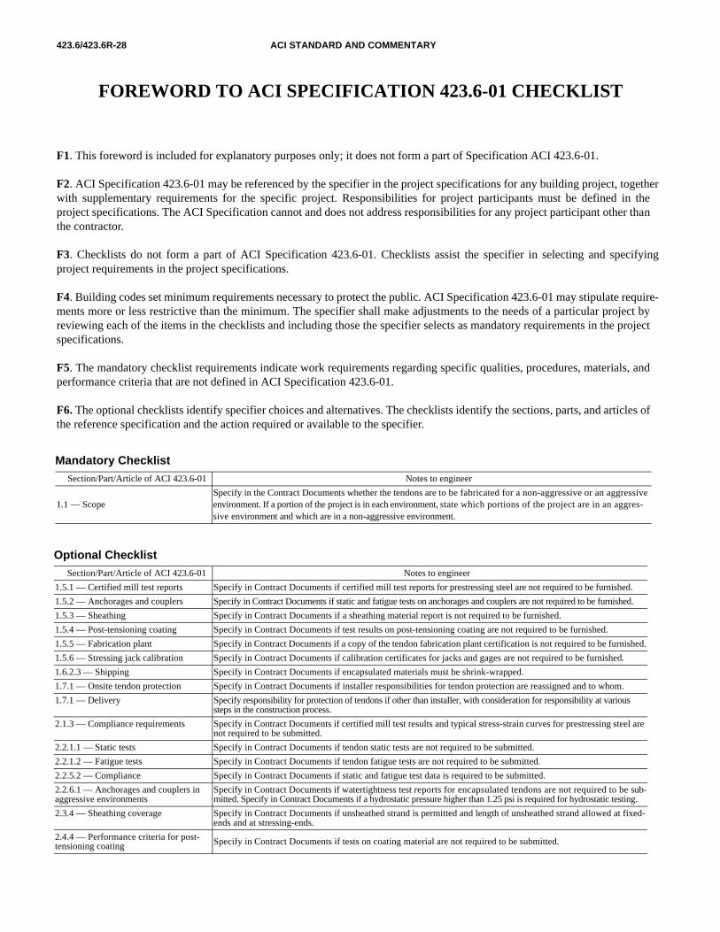
Mandatory ChecklistSection/Part/Article of ACI 423.6-01 Notes to engineer
1.1 — ScopeSpecify in the Contract Documents whether the tendons are to be fabricated for a non-aggressive or an aggressive environment. If a portion of the project is in each environment, state which portions of the project are in an aggres-sive environment and which are in a non-aggressive environment.
F1. This foreword is included for explanatory purposes only; it does not form a part of Specification ACI 423.6-01.
F2. ACI Specification 423.6-01 may be referenced by the specifier in the project specifications for any building project, togetherwith supplementary requirements for the specific project. Responsibilities for project participants must be defined in theproject specifications. The ACI Specification cannot and does not address responsibilities for any project participant other thanthe contractor.
F3. Checklists do not form a part of ACI Specification 423.6-01. Checklists assist the specifier in selecting and specifyingproject requirements in the project specifications.
F4. Building codes set minimum requirements necessary to protect the public. ACI Specification 423.6-01 may stipulate require-ments more or less restrictive than the minimum. The specifier shall make adjustments to the needs of a particular project byreviewing each of the items in the checklists and including those the specifier selects as mandatory requirements in the projectspecifications.
F5. The mandatory checklist requirements indicate work requirements regarding specific qualities, procedures, materials, andperformance criteria that are not defined in ACI Specification 423.6-01.
F6. The optional checklists identify specifier choices and alternatives. The checklists identify the sections, parts, and articles ofthe reference specification and the action required or available to the specifier.
Optional ChecklistSection/Part/Article of ACI 423.6-01 Notes to engineer
1.5.1 — Certified mill test reports Specify in Contract Documents if certified mill test reports for prestressing steel are not required to be furnished.
1.5.2 — Anchorages and couplers Specify in Contract Documents if static and fatigue tests on anchorages and couplers are not required to be furnished.
1.5.3 — Sheathing Specify in Contract Documents if a sheathing material report is not required to be furnished.
1.5.4 — Post-tensioning coating Specify in Contract Documents if test results on post-tensioning coating are not required to be furnished.
1.5.5 — Fabrication plant Specify in Contract Documents if a copy of the tendon fabrication plant certification is not required to be furnished.
1.5.6 — Stressing jack calibration Specify in Contract Documents if calibration certificates for jacks and gages are not required to be furnished.
1.6.2.3 — Shipping Specify in Contract Documents if encapsulated materials must be shrink-wrapped.
1.7.1 — Onsite tendon protection Specify in Contract Documents if installer responsibilities for tendon protection are reassigned and to whom.
1.7.1 — Delivery Specify responsibility for protection of tendons if other than installer, with consideration for responsibility at various steps in the construction process.
2.1.3 — Compliance requirements Specify in Contract Documents if certified mill test results and typical stress-strain curves for prestressing steel are not required to be submitted.
2.2.1.1 — Static tests Specify in Contract Documents if tendon static tests are not required to be submitted.
2.2.1.2 — Fatigue tests Specify in Contract Documents if tendon fatigue tests are not required to be submitted.
2.2.5.2 — Compliance Specify in Contract Documents if static and fatigue test data is required to be submitted.
2.2.6.1 — Anchorages and couplers in aggressive environments
Specify in Contract Documents if watertightness test reports for encapsulated tendons are not required to be sub-mitted. Specify in Contract Documents if a hydrostatic pressure higher than 1.25 psi is required for hydrostatic testing.
2.3.4 — Sheathing coverage Specify in Contract Documents if unsheathed strand is permitted and length of unsheathed strand allowed at fixed-ends and at stressing-ends.
2.4.4 — Performance criteria for post-tensioning coating Specify in Contract Documents if tests on coating material are not required to be submitted.

SPECIFICATION FOR UNBONDED SINGLE-STRAND TENDONS AND COMMENTARY 423.6/423.6R-29
Optional Checklist (cont.)Section/Part/Article of ACI 423.6-01 Notes to engineer
3.1.3 — Installation Specify in Contract Documents installation requirements other than those contained in the PTI “Field Procedures Man-ual for Unbonded Single Strand Tendons.”
3.2.1.1 — Tendon installation (tolerances) Specify in Contract Documents any tolerances that are different from ACI 117-90 or those stated in 3.2.1.1.
3.2.1.3 — Installation Specify in Contract Documents tendon placement tolerances for members other than beams and slabs.
3.2.2.3 — Minimum anchorage cover Specify in Contract Documents anchorage cover requirements required by the governing code that are in excess of those specified.
3.2.5.1 — Sheathing inspection Specify in Contract Documents permissible length of unrepaired ruptured tendon sheathing in non-aggressive envi-ronments.