Embed Size (px)
Citation preview

41st Annual Frequency Control Symposium - 1987
Ku-BAND SATELLITE TWO-WAY TIMING USING A VERY SMALL APERTURE TERMINAL (VSAT)"
David A. Howe Time and Frequency Division National Bureau of Standards
Boulder, CO 80303
Summary
The NBS Boulder Laboratory has recently completed installation of a 6.1 meter Ku-band (14/12 GHz) satellite earth station and has acquired two 1.8 meter portable earth terminals and commercial spread- spectrum modems. This equipment was procured for the purpose of doing two-way time transfer experiments in collaboration with other timekeeping laboratories. Each portable earth terminal, often called VSAT for "very small aperture terminal" when the dish diameter is 1.8 meters or less, is a complete Ku-band earth station. The VSAT can provide full duplex capability to transmit to and receive from a geostationary satellite of the Fixed Satellite Service (FSS). Thus, two-way time comparisons can be done directly between NBS and a portable VSAT through a Ku-band satellite. Phase measurements have been performed of earth station and VSAT facilities in various loop- around schemes using a satellite simulator. Frequency stability o (T) at various carrier-to-noise density (C/No) ratios will be reported. Stability plots have shown that performance is 4 x 10-lo~-l for a C/No ratio of 65 dB-Hz and that this white noise behavior continues to a few days where a is 3 x Absolute phase delay measuremenes show reproducibility to better than 1 ns over a 16 day sample time. This suggests the potential for accuracy to this level given an appropriate calibration. Preliminary results of loop tests through a satellite will be reported.
This paper describes a measurement method which determines the principle time delay constant affecting the accuracy of time synchronization using the two-way technique. The method does not rely on traditional injection and timing of an RF pulse but is an in situ determination having fewer measurement uncertainties.
Y
Introduction
Continuing growth in satellite telecommunications opens up new opportunities for doing accurate transfers of time between suitably equipped laboratories. Wideband Ku-band satellite transponders in the 14/12 GHz band permit the use of small, low-cost earth stations with minimal terrestrial interference and relatively straightforward licensing. The short wavelength of the 12 GHz downlink frequency along with the high power of the satellite transponders yields adequate signal levels even when using only a small 1.8m dish on location. These small earth stations are portable and can be conveniently placed for connection to time standard outputs. When the dish diameter is 1.8m or
*This work has been partially supported by The Rome Air Development Center under contract F30602-85-0055. Contribution of the National Bureau of Standards, not subject to copyright.
"US GOVERNMENT WORK IS NOT PROTECTED BY US COPYRIGHT"
less, the earth station is referred to as a "very small aperture terminal" OK VSAT. The VSAT can provide full duplex capability to transmit to and receive from a geostationary satellite of the fixed satellite service, or FSS.
Recent time transfer experiments using the two-way technique through geostationary satellites have been demonstrated to a level of several nanoseconds [1,2]. The development of a modem specifically designed for this task creates additional opportunity for doing research on the two-way time transfer technique via satellites of the Fixed Satellite Service (FSS) by simplifying the procedure [ 3 1 . The modem uses phase- shift keying modulation in roughly 4 MHz of bandwidth and a pseudo-random noise (PN) sequence as the signal modulation. Therefore, the signal is indistinguishable from the normal communications link noise. There is, of course, an increase in the noise density over the 4 MHz which the signal occupies, but as discussed later this increase can be small enough that no interference is caused to other transponder users.
This paper discusses tests conducted using a Ku-band portable VSAT having a dish diameter of 1.8m with the spread-spectrum modem. This equipment is part of a system directed toward two-way time transfer experiments with various timekeeping laboratories. In addition, tests have been conducted with a satellite earth station facility having a 6.lm dish at the National Bureau of Standards, Boulder Laboratories. Finally, actual satellite loop tests were performed using the VSAT and the NBS earth station.
Facilities
The central component of the present two-way satellite work is a Ku-band earth station having a 6.lm dish located on top of the radio building at NBS, Boulder. It is referred to as the "hub" in the sense that other involved earth stations (VSAT's) have less capability and the use of the hub during experiments helps establish initial satellite connections. A picture of the antenna is shown in the background of Figure 1 and a picture of the earth station equipment which is located about 30 meters away is shown in Figure 2. Figure 3 is a block diagram of the principal parts of the earth station. Pointing of the antenna is by motorized positioners controlled by a microprocessor-based driver. The 6.lm dish has a receive gain of 56 dB and has a low noise amplifier (LNA) with a 2.5 dB noise figure. The transmitted output power is +26 dBm maximum (approximately 0 . 4 watts) measured near the feed. A complete description of the hub is given in reference 4.
The VSAT consists of a complete earth station RF package with 70 MHz input and output intermediate frequency and attached to a 1.8m dish on a free-
1 4 9

standing pedestal. It is shown in the foreground of Figure 1. The dish uses a J-hook prime-focus-feed system. The mount is a simple elevation-over-azimuth assembly using galvanized steel braces arranged in a triangular geometry designed for resting directly on the ground or. in this case, on the roof. Pointing can be done by one person by physically moving the whole terminal to position and locating the satellite by observing the received signal. Since several satellites might be picked up, a unique identifying signal such as a video (television) transmission is very helpful during this pointing exercise. The 6.lm antenna of the hub can automatically point to a given satellite so the signals from it can be used as a reference. This operation is described later.
In-Cabinet and Free-Space Loop Tests
In order to test the various subsystems comprising the ground equipment, several loop-around schemes were employed, which can be divided into two basic categories: (1) in-cabinet tests involving the use of a satellite simulator connected to the transmit and receive (14 and 12 GHz) waveguide ports of the VSAT or earth station, and (2) free-space tests using the satellite simulator connected to horn antennas which are located away from and directed at the VSAT with its dish fully operational. Figure 3 shows the placement of the simulator for in-cabinet tests for the hub earth station. The transmit signal from the 1 watt power amplifier is switched to a power meter with a sample of the signal routed to the input of the simulator. The simulator shifts the frequency by 2.3 GHz and this output is fed to the LNA (low noise amplifier). Figure 4 is a block diagram of the in- cabinet test using the VSAT. The VSAT RF transceiver contains upconverter, power amplifier, LNA, and downconverter all in one package. Connection of the simulator is straightforward. Figure 5 is a block diagram of the free-space loop test used with the VSAT. In this test, the VSAT 1.8m dish is deployed and horn antennas are used with the simulator along with a LNA for gain ahead of the simulator.
With the modem sending and receiving PN spread- spectrum modulation in loop tests, one can analyze the phase stability of the l pps sent round trip through the ground equipment. This sets an upper limit on the expected stability using this equipment. Stability measurements are performed using the two- sample Allan variance of the phase readings from a time-interval counter (TIC). Frequency stability (a vs. z) from one second to a few thousand seconds is shown in figure 6 for three carrier-to-noise-density (C/No) ratios using the hub equipment with an in- cabinet loop test. Carrier-to-noise-density ratio is a figure of merit parameter for communication links and the measurement technique is described in Appendix I. For a C/No of 65 dB-Hz, ay is about 4 x
internal (70 MHz) loop test mode which presumably is a best case condition representing a high C/No ratio. Also plotted in figure 6 is the calculated two-sample variance from the white phase jitter published with the modem. Daily measurements at 65 dB-Hz show fairly good agreement with extrapolated short-term measurements with actual data taken to 4 days and stability of a few x Thus long-term stability is good. For reference purposes, one voice-grade satellite channel typically represents a C/No of about 55 dB-Hz and the modem works reasonably at this
Y
z-l. Also shown is ay with the modem in its
level as shown by the stability measurements of figure 6 .
Figure 7 shows frequency stability results of in- cabinet loop tests performed on the VSAT transceiver. C/No was 75 dB-Hz taken at the upper signal limit of the modem in order to uncover any noise degradation due to the transceiver. Identical results were obtained in the internal loop tests and in-cabinet transceiver loop tests indicating that no degradation had taken place. As an additional test, three modems were connected in series so the loop around involved transmission by one modem, reception by a second with retransmission by the second, reception by a third with retransmission by the third through the VSAT transceiver and simulator and finally reception by the first modem. The frequency stability measurement results in figure 7 show virtually no stability degradation compared to single modems, so the apparatus does well even in this situation.
The VSAT was set up with the 1.8m antenna assembled on its free-standing mount for making range measurements to the translator located up to 26 meters away. Horn antennas and a LNA were added to the translator as shown in the block diagram of figure 5. The distance r is taken from the open end of the feedhorns to the open end (phase center) of the J-hook prime focus feed horn of the 1.8m VSAT dish. This range measurement yields the delay through the VSAT extrapolated to zero distance after removing the translator delay by taking measurements as shown in figure 8. The slope, that is the round trip delay as a function of distance, is determined by the speed of light, and is 14.95 cm/ns. Three measurements were taken and one can see the agreement with this slope in figure 8.
Day-to-day loop-around time delay variations were measured with the VSAT in-cabinet and free-space. These results are plotted in figure 9 and show reproducibility to the 1 ns level. These results are excellent and show the potential for satellite synchronization at this level. There is a discernible increase in the noise level of the free- space data. Its cause is unknown but may be due to translator environmental sensitivity. Nevertheless, the results are encouraging since the measurement is "round trip'' and represents accumulated phase noise.
Satellite Loop Tests
After testing this equipment (the ground segment), we proceeded to loop tests involving actual satellites operating in the domestic Ku-band with assigned uplink between 14.0-14.5 GHz and downlink between 11.7-12.2 GHz. The configuration for doing these satellite loop tests is essentially identical to the free-space tests involving the translator except that the dish antenna is directed at the satellite transponder. Before this operation is done, the first consideration is deciding which satellites make suitable candidates for tests. This decision is dependent on the receiver G/T and transmit EIRP of the ground facility, the satellites in view and their G/T and EIRP for a given connection, the minimum acceptable C/No, and (in this case) the available bandwidth [ 5 ] . Tests were done on three satellites: SATCOM K2 (81 W), SBS 3 (95 W), and SPACENET I1 (69 W). These transponders are primarily used for video transmissions, and are available on a pre-emptible, partial-transponder, occasional-use basis as long as
1 5 0

no interference is caused to other normal traffic. The spread-spectrum modem requires a minimum C/No of 50-55 dB-Hz, the equivalent of about one voice grade channel, spread across a bandwidth of 2 to 4 MHz. In practice, the modem requires more than 60 dB-Hz in order for the demodulator to acquire initial lock because of the effects of any unknown frequency offset errors in the transponder and because of occasional spurious interference in the roughly 4 MHz bandwidth.
Figure 10a shows a block diagram of key elements of the loop test using the hub and its 6.lm dish. The intermediate frequency used into and out of the upconverter and downconverter equipment is 70 MHz and connections are made to the corresponding transmit and receive ports of the modem. A 1 pps and a 10 MHz reference were provided by a rubidium standard and the transmitted 1 pps identification point used in the modulated PN sequence is approximately synchronized with the external 1 pps reference. The transmitted and received 1 pps as determined by the modem are used as start and stop pulses and are measured using a time interval counter having a resolution of 35 picoseconds (rms) per second. The negative going transitions provide triggering. Figure 10b shows a similar setup but instead using the VSAT with its 1.8m dish. In this case, the upconverter and downconverter are part of the transceiver which is attached to the backside of the dish. About 15 meters of coax cable separates the modem's 70 MHz ports from the inputloutput of the VSAT . First loop tests were conducted using the hub earth station and SATCOM K2 located at 81 W. A 4 MHz segment at the high frequency edge of transponder number six was used for the test. The advantage to this kind of segment is its availability and low-cost since it is useful mainly for in-house voice communications by satellite operators and its marketability is not great due to potential interference problems described here. Figure 11 shows spectrum analyzer displays of signals received from SATCOM K2(6B) using the modem and hub earth station. The center of each display marks the frequency of the loop test signal as a clean carrier (figure lla) and with PN modulation (figure l l b ) . Figure llc represents a wider frequency span. Of the normal video signal which may occupy the upper half of transponder number six (designated 6B), there is usually only a small amount of power that extends to the last 4 MHz. However, video signals are frequency modulated and may extend to 24 MHz wide. A full transponder on SATCOM K2 is 54 MHz wide and can carry two video signals. Allowing for a guard band between two video signals, one sees the possibility of interference even at the transponder edges. An adjacent video signal is clearly seen in the spectrum analyzer displays of figure 11. Another form of interference comes from a second transponder which is operating at nearly the same frequency but has orthogonal antenna polarization. This configuration is called the dual polarization mode. Commonly, horizontal and vertically polarized signals share the same satellite permitting greater utilization of the frequency spectrum. If signals are present on the other polarized transponder, then the interference depends on the signals' frequencies, amplitudes, and the degree to which the orthogonal component can be nulled by the earth station antenna. CKOSS- polarization interference is evident in figure 11
from video transmissions from the other transponder. Another potential problem with use of the edge of a transponder is frequency-response roll-off which creates (1) amplitude-to-phase conversion and (2) more difficult decoding by the modem. This roll-off, as it turned out, was not significant in this test and hence was not a problem.
There are other forms of interference than those stated above, but they were negligible in these tests. Interference analysis is described in reference 5. There is, however, a type of interference that is subtle yet significant when a low C/No signal is shared with video transmissions; its effect is called "loading". The transponder output power amplifier is not linear when operating near saturation; that is, its overall gain becomes a function of its input signal level. When there are no other signals on the transponder, a given signal level is retransmitted back based on the satellite's specifications thus yielding a predictable received C/No. Multiple carrier systems (usually non-video) generally require that the received satellite flux density be several dB less than that required for saturated ouput in order to reduce intermodulation interference. However, when one or two video signals share the transponder, the system is usually operated near saturation. If only one video signal occupies the entire transponder, it may be operated at or even above saturation. This can cause the shared PN signal to drop by as much as 6 to 8 dB causing a net reduction in the received C/No by this amount. Since U is increased as C/No is decreased, unexpected cxaracteristics in a may occur if transponder loading is changing Xuring sampled time intervals. A few transponders have an automatic gain step capability that alleviates this problem by adjusting the gain of the transponder so low level data channels are less affected by loading.
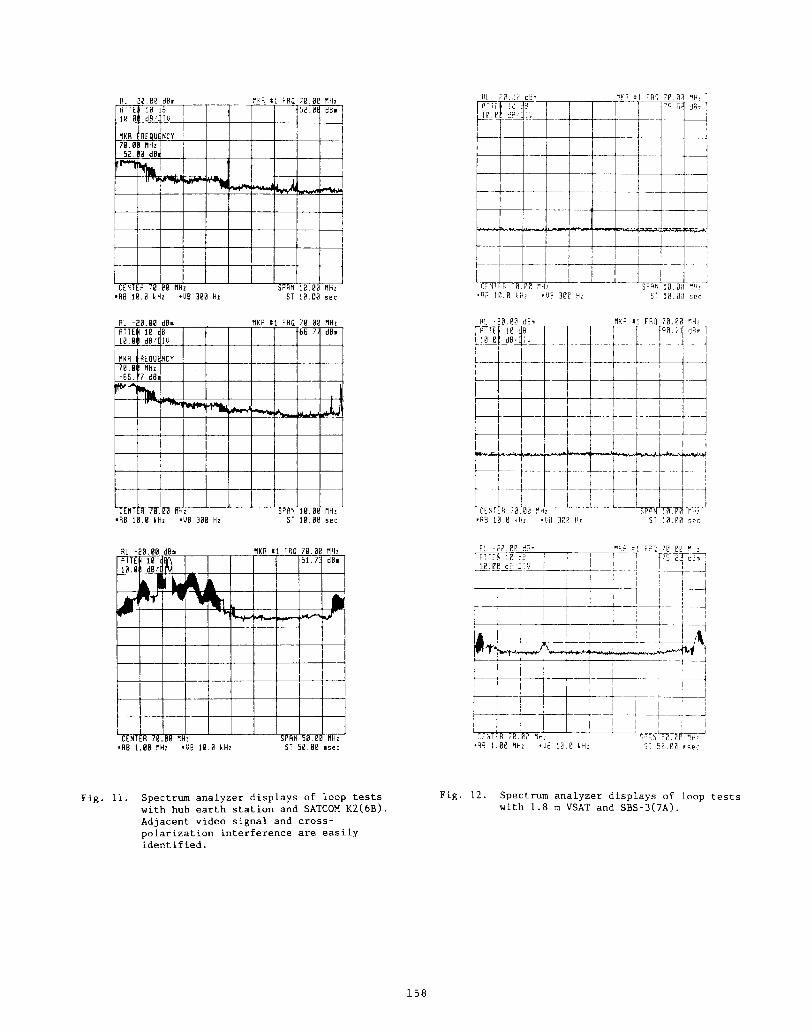
Satellite loop tests were performed using the VSAT and SBS-3 located at 95 W. Setting up the VSAT and actually doing the loop around proved to be a formidable task that is greatly simplified with the availability of the hub earth station. The VSAT with its small dish, low power, and fixed 2.3 GHz transmit/receive offset introduces a new set of problems compared to the hub earth station. In addition to making sure that the link calculation with a given satellite (in this case SBS-3) yields at least 60 dB-Hz, one has to consider the problem of pointing at the correct satellite, assuring that the correct frequency and power level is actually transmitted, and verifying that the spread spectrum signal is being received.
Figure 12 shows spectrum analyzer displays of received signals from the VSAT in a loop test with SBS-3. Clean carrier is shown in figure 12a with a 10 MHz scan and 10 kHz analysis bandwidth, figure 12b is the same display but with PN modulation on, and figure 12c is with PN modulation and with an expanded scan of 50 MHz and 1 MHz analysis bandwidth. Scan time is 10 seconds for figures 12a and 12b, and one can see the difficulty in discerning an identifiable spread spectrum signal in the noise. These displays are typical of the kinds of signals obtained using the modem. The modem usually took several minutes to acquire lock of the return signal from the transponder. A difficulty with using the particular brand of VSAT used here is that the frequency offset between transmitting and receiving is preset at 2.3

GHz and the transponder has an allowable error in its re-transmit offset of +24 kHz. The signal to the modem should be within +l kHz for its best accuracy, but no provision exists for compensating for any frequency error. For this test, the frequency error back to the modem was about 12 kHz which yielded an off-scale condition of a frequency discriminator meter located on the panel of the modem. A convenient method of remotely incrementing the offset in the VSAT in less than 1 kHz steps would be ideal. As it turns out, two-way time transfers will usually OCCUK between a VSAT and the hub earth station, and frequency synthesizers are used at the hub for transmit and receive independently so all frequency errors can be compensated in this configuration.
Time delay through the satellite is about 250 ms in these loop tests. Analysis of the round-trip time (phase measurement) was done again using the two sample Allan variance and its square-root uy, and typical results are shown in figure 13. These results are consistent with in-cabinet and free- space loop tests done on the ground equipment and shown in figure 6. In addition to loop tests described thus far, plots are shown in figure 13 for hub earth station to SBS-3 and SPACENET I1 (69 W), transponder 22. The stability plots follow behavior as expected for white noise except for the case of VSAT and SBS-3 with loading. As described earlier, the effect of satellite loading is to change or "modulate" the C/No causing a change in U
dependent on when and how much loading occurs during the data sample.
Y
Two-way Time Transfer Using A Common Reference Standard
In making estimates of the time transfer accuracy using the two-way technique, signal delays everywhere in the link are of concern. Such delays come from cables, amplifiers, filters, converters, and, of course, the transmission link itself. In doing a time comparison using the two-way time transfer technique, the absolute values of the signal delay are not directly involved; instead, the difference between the transmit path and the receive path is the parameter of interest (the differential delay). Realizing that two transmit/receive facilities are needed for the transfer, it is ultimately the difference of the two differential delays of the involved facilities that is essential (the "offset of the differences"). Appendix I1 derives this offset of the differences term. The accuracy and stability of this term gives an upper limit on the accuracy and stability of the time comparison.
Most measurements of ground equipment delays involve the timing of an injection RF pulse and the detection of the same pulse at a point before the antenna for the transmission portion. The delay measurement for the receive portion is done in the same way but with the injection pulse usually at the LNA and the envelope detector after the appropriate receive chain equipment. There are two common difficulties with this approach. The first is that the pulse injection and detection scheme itself introduces a measurement uncertainty since this is not the way the equipment normally operates. A more favorable measurement would be done in situ. Second, the measurement does not include the antenna and its associated orthomode transducer and feed system. One cannot assume that the antenna's differential delays are zero.
Figure 14 is a diagram showing the basic scheme in which the hub earth station and VSAT simultaneously use a common transponder with two separate spread spectrum sequences (near orthogonal [31) timed by a common 1 pps reference. A modem is used at the hub and another is used at the VSAT and the transmit sequence (Tx) is indicated as "0" for the hub and "1" for the VSAT. The receive sequence (Rx) is "l" for the hub and "0" for the VSAT so each earth station receives the sequence from the other one and not itself. This is the basic configuration used between separate locations doing a simultaneous two-way time transfer. In the case here, the two earth stations are colocated with a common 1 pps reference thus allowing a direct measurement of differential timing errors. Furthermore, this approach allows a direct measurement of system accuracy and stability [l]. Although no data has been analyzed at this time, the concept has been demonstrated using the hub and VSAT equipment operating simultaneously through SBS-3 using two separate spreading sequences. Time interval counter measurements need to be taken and the results compared as described in Appendix 11. Figure 15 shows a method of directly measuring the offset of the differences with one time interval counter (TIC) and hence establishing a calibration with the use of these earth stations.
Conclusions
A number of tests have been performed on commercially available Ku-band satellite telecommunications equipment and, in particular, on a small, self- contained earth terminal (VSAT). The VSAT is used in conjunction with precise time transfers via satellite to a central hub facility at NBS, Boulder, with the commensurate differential time offset between VSAT and hub having been directly measured. Tests have also been conducted using a specialized spread spectrum modem designed for two-way time transfer. Short term stability data with this equipment in three different loop-around tests (in cabinet, free space, and via satellite) have been performed under various conditions and various C/No ratios. Satellite loop tests used SATCOM K2 (81 W), SBS 3 (95 W), and SPACENET I1 (69 W). Loop tests with the hub and with the VSAT were also described. Stability performance is on the order of 4 x 10-lo~-l for a C/No ratio of 65 dB-Hz. Long term stability data in a satellite loop test has not yet been obtained, but in-cabinet and free-space loop tests of the ground equipment using a satellite simulator show that this white noise behavior continues to a few days where o is 3 x Absolute phase delay measurements show Y
reproducibility to better than 1 ns over a 16 day sample time. Future tests will be done to gather long term stability measurements and long term reproducibility in loop tests involving actual satellites.
This paper described a direct measurement technique for determining the differential offset term for two satellite earth stations (one, a portable VSAT) in close proximity to each other using a common satellite and a common reference clock. Usually, the differential offset constant has been determined in satellite time comparisons by measuring delays of injected RF pulses, a method which has certain inaccuracies. The method used here provides a direct measurement of the delay for two earth stations under actual operating conditions. The direct measurement
152

makes the fewest assumptions regarding the uncertainty in the determination of the differential offset constant.
Future work will be directed toward analysis of the accuracy and stability of the common-view/common- clock scheme as outlined here. At the present time, the plan is to incorporate more extensive instrument control and automated data analysis to facilitate data reduction and documentation of results. The ground segment and satellite loop tests of frequency stability point to an accuracy capability in the range of a few nanoseconds OK better and stability of several x 10-lo~-l for a C/No ratio of 65 dB-Hz.
Acknowledgements
The author is grateful to D. Wayne Hanson of NBS for valuable guidance and discussions in all aspects of this work. He also wishes to.acknowledge the help of Ray Conover of Conus Communications for extensive partial transponder availability and Bob Trotter and Terry Maraia of the NBS Radio Frequency Management Office for expediting the VSAT authorization.
Appendix I
Measurement Methods
Of interest in this paper is a relationship between standard frequency stability measurement techniques and standard satellite, signal-to-noise ratio parameters. In the case of frequency stability the measurement performed is the two-sample Allan variance of the phase noise of the ground segment in both in-cabinet and free-space, loop-around schemes. Frequency stability measurements from one second to a few thousand seconds were performed for various carrier-to-noise-density (C/No) ratios. Carrier-to-noise density ratio is a general figure of merit parameter for a satellite communications link. Frequency stability data also was taken at one day intervals to look at long term stability and its agreement with extrapolated short term stability results. The actual C/No measurement is made using a spectrum analyzer sampling the unmodulated pure RP carrier of the modem compared to the density of noise in a 1 Hz bandwidth. The spectrum analyzer had a minimum resolution bandwidth of 10 Hz but the noise component was white and allowed straightforward calculation to 1 Hz bandwidth. The analyzer incorporated a correction for doing noise bandwidth measurements at various analyzer settings. These corrections were found to be accurate to the rated specification of 1 dB by scanning the shape of the response curve and scaling the bandwidth as high as 100 kHz and (again assuming white noise) seeing correct closure of the equivalent noise bandwidth at 1 Hz. At low (C + N)/N ratios, it is difficult to accurately measure the signal level because of the presence of the noise component. To overcome this difficulty the carrier signal was introduced at a higher level, accurately measured by the analyzer, and then a precision attenuator was applied to only the carrier in order to reduce its level to a known value.
Some data which is presented in the documentation which accompanies the modem is useful for the analysis of frequency stability presented here.
Figure 6 shows a plot from data of the white noise phase jitter versus carrier-to-noise density ratio [2]. A value for U can be computed and the value for 75 dB-Hz is included with the data. If we assume that modem data is the classical variance about the mean of the phase jitter (U,') then the relationship to the Allan variance is r6.71
Appendix I1
"Offset of the Differences" Measurement
For measurement of the differential delay terms which show up in the two-way transfer scheme, one can use the portable dish in conjunction with a fixed ground station. With a common clock, one can calibrate out these differential delay terms. This is shown in the following analysis in which TI(1) and TI(2) are the time interval counter readings at locations 1 and 2 respectively in a two-way time transfer involving locations 1 and 2.
TI(1) = AT + u/c(2) + sat.path(2 to 1) + d/c(l) and TI(2) = -AT + u/c(l) + sat.path(1 to 2) + d/c(2). AT is the time difference of the clocks at 1 and 2, u/c denotes time delay through the up-conversion at locations 1 or 2, and d/c denotes the down- conversions. Sat.path represents the total signal path delays up to and through the satellite and down for signals going from location 1 to 2 and vice- versa. Sat.path includes any delays due to the earth's rotation. AT can be calculated as
AT = ${[TI(l)-TI(Z)] + [u/c(l)-d/c(l)] - [u/c(2)-d/c(2)] + sat.path(1 to 2) - sat.path(2 to l)}.
If we assume sat.path time delays are reciprocal, except for the time difference term due to the earth's rotation, then sat.path(1 to 2) = sat.path(2 to 1) + GT(rotation) and we have AT = t{[TI(l)-TI(2)] + [~/c(l)-d/c(l)]
- [u/c(2)-d/c(2)] + GT(rotation)}. Now with the two earth stations co-located and using a common clock,bT(rotation) = 0 and AT = 0 and the difference in the u/c's and d/c's is explicitly the difference in the time interval counters. We have
TI(Z)-TI(l) = [u/c(l)-d/~(l)] - [u/c(2)-d/c(2)1 = constant.
This constant which is the offset of the differences can be used for subsequent two-way time transfers using the earth stations, one of which is a portable VSAT which can be located with another earth station to yield a "calibration" of that earth station.
In doing two-way time transfer experiments through geostationary satellites, there exists a limit on the
153

knowledge of the time delay difference between the outgoing signal and the received signal. This non- reciprocity is due to the difference of paths and the difference of equipment between the uplink and the downlink. Using spread spectrum modulation with different pseudorandom codes for the two directions of time transfer, it is common to assume the difference in the transmission paths to and from the satellite as well as through the satellite transponder to be zero and the earth's rotation correction can be computed [8]. Certainly the ionospheric dispersion and the effects of water vapor dispersion are small (below 100 PS) [g]. The most significant time delay difference error enters in the ground segment. The use of cables, interconnects, conversions, and test points for instruments creates the most significant absolute delays and thus the opportunity for significant differential delays.
References
[ l ] "Time Comparison Experiments with Small K- Band Antennas and SSRA Equipments via a Domestic Geostationary Satellite," M. Imae, et. al., IEEE Transactions on I & M, Vol. IM-32, No. 1, March 1983, pp. 199-203.
[2] "Timing by Satellite: Methods, Recent Developments, and Future Experiments," D. Kirchner and W. Riedler, Proc. Int. Symp. on Satellite Transmissions, Graz. Austria, 25-27 September, ESA SP-245 (No. 1985).
[3] Mitrex 25000 Documentation, Ph. Hartl, et al., Institute for Navigation, University Stuttgart, Germany, January 1985.
[41 "Stability Measurements of Ku-Band Spread Spectrum Equipment Used for Two-way Time Transfer," D. A. Howe, Proc. 18th Annual Precise Time and Time Interval (PTTI) Applications Planning Meeting, December 1986. Also "Progress Toward One Nanosecond Two-way Transfer Accuracy Using Ku-Band Geostationary Satellites," D. A. Howe, IEEE Transactions on Ultrasonics, Ferroelectrics and Frequency Control, Special Publication on time and frequency (1987) to be published.
[5] "Digital Communications, Satellite/Earth Station Engineering," K. Feher, Prentice- Hall Inc., Englewood Cliffs, N . J., 1981. Also "Digital Satellite Communications," T. T. Ha, Macmillan Publishing Company, New York, N. Y., 1986.
[ 6 1 "Characterization of Frequency Stability," J. A. Barnes, et. al. IEEE Transactions on I & M, Vol. 1-20, May 1971, pp. 105-120.
[ 7 ] Private communication, D. W. Allan, National Bureau of Standards, 325 Broadway, Boulder, CO. 80303.
181 "Practical Implications of Relativity for a Global Coordinate Time Scale," N. Ashby and D. W. Allan, Radio Science, Vol. 14, No. 4 , 1979, pp. 649-669.
[9] "Atmospheric Absorption and Dispersion of Microwave Signals in the Centimeter and Millimeter Region,'' H. A. M. Al- Ahmad, H. Smith, E. Vilor, Portsmouth Polytechnic Internal Report No. 84/5, January 1984.
Fig. l. 6.1 meter antenna used as a hub (shown in background) and 1.8 meter VSAT (shown in foreground).
154

Fig. 2. Earth station equipment.
+ W dB !W
MAX
MODEM
START STOP 'LNA localed I" cabsnet 13, Imp lell dala. relocated m d,Sh tor 1ree space Wllf TIME IN1
COUNTER
5 MHz
Rb FREO SlANOARD
Fig. 3. Block diagram of principal parts of the hub earth station.
155

1
F i g . 4 . Block diagram of VSAT in-cabinet loop- Fig. 5. Block diagram of VSAT free-space l o o p - around test. around test.
LOOP-AROUND TEST, +(T) AT DIFFERENT CIN,
Fig. 6. Frequency stability measurements of hub earth station equipment in an in-cabinet loop test.
156

VSATlModem Loop Tests, oy(d of Different Modems
o Int. loop test U1 v Int . loop test U2 U 3-way loop test with VSAT 182
10 -10 l 0
0
0
B 0
V
0
V 0
0
T- Seconds
Fig. 7 . Frequency stability measurements of VSAT equipment in an in-cabinet loop test and using three different modems for comparison.
Range r, meters
Fig. 8. Three VSAT free-space range measurements can be extrapolated to zero distance to determine delay with the dish. Time interval counter ( T I C ) readings are a function of range K. Slope is exactly expected result and extrapolation to zero is straightforward.
In-Cabinet VSAT Loop-Around Time DelaylDay
1.360 /
1.355 I I I I ! l I , I I , I l I I ,
1 5 10 15
Free-Space VSAT Loop-Around Time DelaylDay
I I I l I / I I ~ l / I I ~ l
1.615
1.610 / / I l 1 / I I l , , l , I ~
1 5 10 15 Days
Fig. 9. Day-to-day loop-around time delay using VSAT in-cabinet and free-space showing total in-cabinet and free-space loop-
VSAT . around time delay reproducibility using
Satellite/HUB Loop Test ,,/O SatellitelVSAT Loop Test
a b
Fig. loa. Block diagram of principal part of satellite loop tests with hub.
Fig. lob. Block diagram of principal part of satellite loop tests with VSAT.
RL - ? E E 2 dBn
* A B 1 B . B k H z SUB 3 8 0 Hz SI 1B.OE 5 e c
'RB l E . O k H z SUB 300 H z SI 10 BE 5 e c
RL -20.88 dB. R K R 8 1 F R Q 7 B . E e HHz
.RB 1.00 HHz * V B 1E.B k H z SI 5 0 . 0 8 .sec
Fig. 11. Spectrum analyzer displays of loop tests with hub earth station and SATCOM K2(6B). Adjacent video signal and cross- polarization interference are easily identified.
Fig. 12. Spectrum analyzer displays of loop tests with 1.8 m VSAT and SBS-3(7A).
1 5 8

Satellite Loop Tests, Various I I I l I 1 1 1 1 I I I I I I I I I I
A SATCOM K2 (6B) - Hub, 50 dB-HZ - o SBS-3 (7A) VSAT, 60 dB-HZ 0 SBS-3 (7A) - VSAT, 60 dB-Hz (w/loading) -
A + SBS-3 (7A)- Hub, 65 dB-HZ X SPACENET I1 (22) C-, Hub, 60 dB-HZ
0
- - -
$ A
- - -
O A
9 0 A
Q + o
X t I I I 1 1 1 1 1 1 I I I I l I I I I , +
loo 10’ lo2 7 -+ seconds
Fig. 13. Frequency stability measurements of loop tests involving hub and VSAT with three satellites.
Transpondel
Two-way Time Transfer with a Common Reference Standard
A t
& Relerence
Fig. 14. Common view/common clock scheme for measurement of ground-segment differential delay constant.
1 5 9

Transponder
“Offset of the Differences” 0
Two-way Time Transfer Measurement //
UIC & D C Equipment
Modem
U Tlme Int. Counter
Fig. 15. Technique for direct measurement of offset of the differences. If the left time interval counter (TIC) is zero (representing identical on-time transmission of 1 pps from hub and VSAT), then right T I C is exactly the offset term.
160