Embed Size (px)
Citation preview

“NETWORK OF DANUBE WATERWAY ADMINISTRATIONS”
South-East European Transnational Cooperation Programme
STATUS QUO REPORT FOR WATERWAY MAINTENANCE ADMINISTRATION OF THE NAVIGABLE CANALS SH CONSTANTZA
Document ID: O 4.6.
Activity: 4.1.
Author / Project Partner: Date: Version:
Moren Abdurafi/ACN 15.02.2010 1.0 - final

1
TABLE OF CONTENTS
LIST OF ABBREVIATIONS ....................................................................................................................................2 SCOPE OF DOCUMENT.........................................................................................................................................3 A. INTRODUCTION ………………………………………………………………………………………………………....4 A.1. RESPONSIBILITY FOR WATERWAY ADMINISTRATION- INSTITUTIONS………………………………….4
A.1.1. OBJECTIVE PRESENTATION.................................................................................................................4 B. CHARACTERISTIC OF WATERWAY.................................................................................................................6 B.1. GENERAL HYDRO TECHNICAL SCHEMA OF DANUBE BLACK SEA AND POARTA ALBA MIDIA NAVODARI WATERWAYS ...................................................................................................................................6 B.2. DANUBE BLACK SEA CANAL....................................................................................................................6 B.2.1. CONSTRUCTIVE CHARACTERISTICS .................................................................................................6 B.2.2. CHARACTERIZATION FROM MORPHOLOGICAL(SEDIMENTS ) POINT OF VIEW ..........................7 B.2.3. WORKS ALONG THE DBSC...................................................................................................................9 B.2.3.1. LOCKS .............................................................................................................................................9 B.2.3.2. CERNAVODA COMPLEX PUMPING STATION...............................................................................9 B.2.3.3. COMMERCIAL AND PASSENGERS PORTS ................................................................................10 B.3. POARTA ALBA-MIDIA NAVODARI CANAL...............................................................................................11 B.3.1. CONSTRUCTIVE CHARACTERISTICS................................................................................................11 B.3.2. CHARACTERIZATION FROM MORPHOLOGICAL POINT OF VIEW..................................................12 B.3.3. WORKS ALONG THE PAMNC(PARAMETERS)..................................................................................16 B.3.3.1. LOCKS.............................................................................................................................................16 B.3.3.2. PORTS AND MOORING POINTS....................................................................................................17 B.3.3.3. ADJACENTS WORKS....................................................................................................................17. C. WATERWAYS MAINTENANCE.......................................................................................................................18 C.1. MAIN ACTIVITIES FOR WATERWAY MAINTENANCE –HIDROLOGY, SURVEY, SIGNALIZATION....................................................................................................................................................18 C.1.1 HYDROLOGY(GENERAL INFORMATIONS) ......................................................................................18 C.1.1.1. HYDRO-METEOROLOGICAL PARAMETERS..............................................................................18 C.1.1.2. HYDROLOGICAL PARAMETERS.................................................................................................18. C.1.2. RIVER BED MEASUREMENTS(GENERAL INFORMATIONS) ..........................................................19 C.1.3. BOTTLENECKS ...................................................................................................................................21 C.1.4. SIGNALIZATIONS................................................................................................................................23 C.2. REPORT FOR RIVER ENGINEERING CONSTRUCTIONS AND EXECUTION......................................24 C.2.1. DANUBE BLACK SEA CANAL...........................................................................................................24 C.2.1.1. WATERWAY……………………………………………………………………………………………….24 C.2.1.2. RIVER BANKS................................................................................................................................25 C.2.1.3. PORTS AREA.................................................................................................................................31 C.2.1.4. PROJECTS ALREADY DONE( 2001 – 2009 period ) ..................................................................34 C.2.2. POARTA ALBA MIDIA NAVODARI CANAL.......................................................................................35 C.2.2.1. WATERWAY...................................................................................................................................35 C.2.2.2. RIVER BANKS................................................................................................................................35 C.2.2.3. PORTS AREA ................................................................................................................................38 C.2.2.4. PROJECTS ALREADY DONE ( 2001 – 2009 period ) .................................................................39 C.2.2.5. PROJECTS IN EXECUTION .........................................................................................................39 C.2.3. CCOMMON SECTOR, WATERWAY MAINTENANCE .....................................................................40 C.2.4. WATERWAY MAINTENANCE IN THE ICE PERIOD ........................................................................40 C.2.5. WATERWAY MAINTENANCE IN THE LOWEST LEVEL PERIOD ..................................................40 C.2.6. WATERWAY MAINTENANCE IN THE HIGHEST LEVEL PERIOD ................................................41 C.2.7. REPORT ABOUT THE PREVENTION AND RESTORATION OF FLOOD DAMAGES ...................41 C.2.8. PLANNING FOR LOCK MAINTENANCE AND REPAIRING ...........................................................44 C.2.8.1. RESPONSABILITY ...................................................................................................................44 C.2.8.2. THE MAINTENANCE OF THE EQUIPMENTS AND INSTALLATIONS AFFERENT TO THE NAVIGABLE CANALS .........................................................................................................................................44
C.2.8.3. PLANNING THE MAINTENANCE WORKS OF THE EQUIPMENTS AND INSTALLATIONS AFFERENT TO THE NAVIGABLE CANALS.........................................................................................................45

2
LIST OF ABBREVIATIONS
ABBR. Abbreviation
ACN Administration of the Navigable Canals SH , Constantza,
Romania
DBSC Danube Black Sea Canal
PAMNC Poarta Alba- Midia Navodari Canal
AFDJ River Administration Of the Lower Danube

3
SCOPE OF DOCUMENT Activity’s 4.1. „Access and improve methods , processes and procedures for waterway maintenance” main objective is to prepare a general status quo report regarding the river stretch characterization, from hydrological, morphological and navigations conditions point of view , equipments, financial resources for waterway maintenance , workflow internal and external. According to description of the work SWP 4.1. ( task 4.1.1.) every partner shall prepare a status quo report for waterway maintenance and describe in their report the waterway maintenance activities and what are the problems. The status quo report shall, at least, contains relevant information about:
- hydrology - survey - fairway axis - limits and gauge - floating and coastal signalization - signalization for high and low level - dredging works , - maintenance works and hydrotechnical construction - fairway information - report on the prevention and restoration of flood damages

4
A. INTRODUCTION
A.1. RESPONSIBILITY FOR WATERWAY ADMINISTRATION- INSTITUTIONS
A.1.1. OBJECTIVE PRESENTATION
After the opening of the Rhine – Main - Danube Canal, the Rhine and the Danube form now a major trans-European shipping artery, in length of approx. 3500 kilometers, which links the North Sea with the Black Sea and which connects the inland navigation networks of 13 Central and Western European countries.
Connecting the Trans-European Navigation System with a first size sea port like Constanta, on an shorter route with over 400 km than the existing one passing through Sulina, considering that at the end or from the Black Sea an important intermodal transport platform has developed, where the largest vessels transiting the Suez and Bosporus can dock and operate, provide especially favorable economic conditions and a rapid development of the entire corridor that stretches from Rotterdam to Constanta.
Therefore, we can state that both Danube - Black Sea and Poarta Alba - Midia Navodari waterways as well as the Constanta-South port which form objectives that bring value to the entire Rhine - Danube Trans-European Navigational System of navigable canals.

5
Through the opening of the two important waterways, Danube - Black Sea
Canal (1984) and Poarta Alba - Midia Navodari Canal (1987), that cross Dobrogea this have become the main source of water used for all purposes, including potable water and the supply for the bordering settlements of the Black Sea seashore.
Ensuring the water quality in the waterways at optimal parameters is an essential condition of which further development of the South Dobrogea and the Black Sea seashore depends.
Completing the existing and future quality requests of water uses represents a key issue. The obligation to water protection against pollution also derives from the current legislation regarding the environment and water protection.
Further more, it is imposed the necessity of ensuring sanitation and water scenery of the Danube - Black Sea and Poarta Alba - Midia Navodari waterways in the purpose of maintaining ecological balance and meeting the aesthetic requests, recreational and hygiene requirements in the area.The administration, operation and maintenance of the Danube - Black Sea and Poarta Alba - Midia Navodari waterways is done by the National Company "Administration of Navigable Canals" SH.
Environmental and water protection at the national company’s level is done through the Bureau of Water Management – Environmental Protection on the basis of the Water Management Authorization and the Environment Protection

6
Authorization, that adjusts the terms of environmental protection work carried out on Danube - Black Sea and Poarta Alba - Midia Navodari waterways
B. CHARACTERISTIC OF WATERWAY B.1. GENERAL HYDRO TECHNICAL SCHEMA OF DANUBE BLACK SEA AND POARTA ALBA MIDIA NAVODARI WATERWAYS
The Hydro-technical scheme of the Danube - Black Sea and the Poarta Alba -
Midia Navodari navigable channels has a complex character being sized to serve the following purposes:
- navigation; - supplying water for irrigation, drinking and industrial purposes, for producing
hydroelectric energy and nuclear power; - receiver for evacuation of cleared wastewater and water that comes from
draining; - the adjustment of leakage from its own hydrographic basin, the defense
against flood. The hydro-technical scheme provides qualitative and quantitative
management of water from the navigable canals in normal operating conditions and in accidental evacuation conditions caused by generalized or partially generalized fallen in the hydrographic basin.
B.2. DANUBE BLACK SEA CANAL
B.2.1. CONSTRUCTIVE CHARACTERISTICS The Danube – Black Sea canal makes the connection between the Danube
river and the Black Sea. The length of the canal between the Danube at Cernavoda km 299, 1 and the
Black Sea at Agigea is of 64,410, being compound of 3 functional areas with the following characteristics:
- Canal Pool I - 4.1 kilometers, situated between the Danube and Cernavoda twin locks;
- Canal Pool II - 58 km, between Cernavoda and Agigea twin locks; - Canal Pool III - 2 km, between twin locks Agigea and the Black Sea. DBSC was constructed between 1975 and 1983 in the basis of general
execution project run by MTTc, as investment holder and general designer, approved by 300/1978 Decree. Levels, depths, transport capacities, speeds on DBSC: Canal Pool I Canal Pool II Canal Pool III

7
- maximum level (mrMB) 12,0 8,50 0,50 - normal level (mrMB) 7, 0 7,50 - 0,50 - minimum level (mrMB) 2,75 7,00 - 1,10 - channel bottom share (mrMB) - 1,50 0,50 - 7,50 - water depth per level :
normal (m) 8,50 7,00 7,0 minimum (m) 4,50 6,50 6,40
- water transport capacity (mc/s), for: maximum levels 335 900 900 normal levels 320 320 320 minimum levels 310 310 200
- longitudinal speeds, water limitations (mc/s) 0,5 1,4 1,4
Danube attraction area: - attraction point Danube – right bank, km 299 + 100 ; - normal level opening at the Danube: 0,4 km; - free level attraction; - trapezoidal section; - bottom cote = - 1,50 mrMB; - water depth : normal level = 8,50 m
minimum level = 4,50 m; - longitudinal speed at – maximum limit in normal terms of exploitation: 0,3 m/s - longitudinala speed: - maximum limit in normal terms of flood transit: 0,5 m/s; - transit floods : normal level : 335 mc/s;
minimum level : 320 mc/s
B.2.2. CHARACTERIZATION FROM MORPHOLOGICAL(SEDIMENTS ) POINT OF VIEW
The waterway system between the Danube and the Black Sea is located in the central part of Dobrogea, on Cernavoda – Constanta axis, along which there are strongly outlined two different morphological units: - Carasu Valley – tributary to the Danube. - The crest area – plateau.
The hydrographical system of the area crossed by the canal is characterized by large valleys,hardly sketchy towards the starting point, without water along the entire year, but with significant flows at precipitations.
The hydrographical basin of the canal has a surface of approx. 875 kmp. In its way towards the sea, the line intercepts 14 valleys on Carasu Valley, and 13 affluent valleys on the plate area.
These valleys were connected to the canal with adequate works.

8
On the line of the Danube – Black Sea waterway, the Carasu Valley plain represents a low altitude depression area which descends the relief both from the North and South, from 150-200 m levels to levels of 4-20 m in the Valley line. Along Carasu Valley, the land has levels of 4-5 m in the area of Cernavoda – Saligny, rises up to 12-14 m in the area of Poarta Alba and reaches 30 m in Basarabi area. On the plateau area of the Danube – Black Sea canal, the land levels reach 50-70 m on most of the line length.
In the plain sector on the Carasu Valley the canal section was realized mostly in deposits of quaternary age, represented by clays, loess, silt, slurry, sometimes even peat (crossing Medgidia town), and sometimes sands and gravels, all with alluvial origin. With local character, by cutting off some variants imposed by the geometrical elements of the line or of the crosssection,the excavations unearthed older formations, namely chalky limestone and marls (in the area of Cernavoda lock), sands, marls and altered limestone (km 12; 18; 22; 24 and 26), Aptien clays, grit sands and altered limestone (km 30; 36-38 and 39-40).
On the plate sector, between Basarabi and Agigea, the canal section outlined deposits of Sarmatian, made of chalks; the Sarmatian made of an alternation of limestone, clays and sands with discontinuous sequence; the Quaternary represented by red clays horizons, sometimes grey with limestone blocks of 0.5-3 m thickness, red or brown clays with over 20 m thickness and loess and silt of 0.5-15 m thickness. In its way towards the sea, the canal needed a large volume of excavations in the complex of structured red clays, sensitive at atmospheric agents, with a thickness up to 35 m, and which, by soaking gets disadvantageous physical-mechanical characteristics.
On its last part, the canal section is made of recent deposits of silt slurry and beach sands; an exception is Agigea lock area for which it could be identified and chosen a sector with the limestone near the surface, which was recommended for the emplacement and foundation of this important canal work.
From this hydro-geological point of view, the canal area is characterized by the underground water presence at the depth of 0,5-0,3 m on the first part of Carasu Valley and of 5…10m on Poarta Alba – Basarabi sector. In the pre-quaternary formations met on Carasu Valley the ground-water table is at 15-30 m deep,

9
sometimes being under pressure, locally even artesian (the area of the South – West Saligny hill stopper – Cernavoda lock and the sectors km 22; 26 and 36-38). The underground flow in the valley plain is conditioned by the water level in the canal, usually from the escarpment towards the valley line.
On the plate area the quaternary aquifer is cantoned at the loess base, at depths of 4-10 m, and towards the coastline it correlates with the level of Agigea Lake. The underground flow of this aquifer is orientated towards the depression areas (Valea Seaca, Agigea Valley etc.). The waters from the pre-quaternary system are cantoned in the system of the limestone or chalk formations fissures and in the sands layers and they are under pressure. The climate in the canal area has a variable character from the East european continental climate to the pre-mediterranean temperat climate of the Balkan Peninsula and presents important diurnal and annual oscillations in the air temperature, recording low precipitations quantities. The average temperature of the summer months is +22 degree C, maximum +43,5 degree C, and during winter -1 degree C, maximum -33,5 degree C.
B.2.3. WORKS ALONG THE DBSC
B.2.3.1. LOCKS
– two twin pieces at Cernavoda and Agigea, with the following main purposes: Cernavoda Agigea
- useful lock chamber length (m) 310 310 - useful lock chamber width (m) 25 25 - miter sill’s foundation depth: upstream – minimum level (m) 4,5 7,0
- maximum level (m) 14,0 8,5 downstream - minimum level (m) 7,0 6,4
- maximum level (m) 8,5 8,0 Miter sill’s foundation depth at normal operating level - crest cote (mrMB) 7,0 11,0 - lock chamber floor cote (mrMB) 1,5 - 7,5 The locks are dimensioned for a navigational traffic of 70 million tones/year, with a full capacity of transit of 80 million tones/year.
B.2.3.2. CERNAVODA COMPLEX PUMPING STATION
- located on the derivational canal has the following characteristics of the pumping equipment:

10
Aggregate OP 6 - 185 Aggregate AV–2800 - aggregates number (piece) 8 5 - necessary Q for pumping (mc/s) 25 - 205 - flow / aggregate (mc/s) 15 23 - 25 - high of the pumping (m) 0,5 - 5,0 - power (Kw) 1000 1000 - 750 Total installed flow varies between 200,3 – 209,6 mc/sec, according to the
level differences between canal pool I and canal pool II. B.2.3.3. COMMERCIAL AND PASSENGERS PORTS – on the canal route there are located 2 ports: - Medgidia, on the Danube Black Sea canal at km 36 + 700 ; - Basarabi, on the Danube Black Sea canal at km 24 + 500.
The main technical – functioning features of the ports are: Medgidia Basarabi - operating capacity (mil. t / an) 11,5 0,7 - minimum levels (mrMB) 7 7 - maximum levels (mrMB) 8,5 8,5 - crest foundation level (mrMB) 11,0 11,0 - front tunes, for disentanglement and recovery convoys (m) 903 300 - acvatoriu surface (Ha) 19 14 - berths number 23 14 - total length of the quay (m) 2487,33 920
The constructive system foresees quays like Estacada with a vertical face, foundation on the column at Medgidia port and on the mulled walls Kelly model at Basarabi. At the technical and passengers berths there have been provided lop sided quays – ship moorage being made with the help of fixed pontoons.
The navigation on the canal is made for merchandise and passengers transport with river, river – maritime self propelled, small unpropelled vessels forming a pushed or couple convoy, which subscribe the following gauges:
- maximum length 296 m - maximum width 23 m - maximum height at the floating line And up to the highest point 16,5 m - maximum current draft 5,5 m - maximum draft with speed restrictions 6,0 m - maximum navigational speed 12 km/h

11
B.3. POARTA ALBA-MIDIA NAVODARI CANAL
B.3.1. CONSTRUCTIVE CHARACTERISTICS
The canal makes the connection between Danube Black Sea Canal – Black Sea and Luminita port from the Tasaul lake. The legth of the canal between Danube Black Sea canal(at Poarta Alba - km 34 + 669) and the Black Sea at Navodari is of 27,757 km, at which it is added the connection with Luminita port of 5,0 km. The canal has 3 functional areas:
- Canal pool I : length = 15,2 km, between the confluence DBSC and the twin locks Ovidiu;
- Canal pool II : length = 10,3 km, between the twin locks Ovidiu and Navodari locks,
plus 5,0 km, the connection with Tasaul lake (Luminita port) ; - Canal pool III : length = 1,1 km , between the twin locks Navodari and
Black Sea Levels, depths, transport capacities, speeds on Poarta Alba - Midia Navodari Canal: ----------------------------------------------------------------------------------------------------------------- Specification Canal pool I Canal pool II Canal pool III ----------------------------------------------------------------------------------------------------------------- - maximum level (mrMB) 8,50 2,25 0,5 - normal level (mrMB) 7,50 1,25 - 0,5 - minimum level (mrMB) 7,00 1,00 - 1,1 - bottom canal cote (mrMB) 2,00 - 4,25 - 6,0 - the water depth at level: - normal (m) 5,50 5,50 5,50 - minimum (m) 5,00 5,25 4,90 - water transport capacity (mc/s), at : - normal levels 42 - 51,6 38,2 - 51,0 38,2 - 51,0 - minimum levels 42 38,2 38,2 - longitudinal speeds, water limit (m/s) 0,13 - 0,19 0,17 - 0,23 0,17 - 0,23
Poarta Alba Midia Navodari Canal is dimensioned for a maximum capacity of
transport of up to 24-25 millions tones/year, for navigation both ways with a convoy composed of a 3000 tones barge and a pusher of approximately 800 HP.
The most important source of water of the navigable canals is the river Danube which provides water in the waterways in different ways such as:
a) Gravitationally when the level of the Danube is higher than the level of the Danube Black Sea Canal;

12
b) Through lockage when the level of the Danube is superior to that on the Danube Black Sea Canal;
c) Through pumping with the Cernavoda Complex Station of Pumping. The navigable canals can also receive water along the way from the following
sources: meteoric waters, waters collected from the hydrographic basins of the affluent valleys of the waterways; pumping stations of the waters from draining and in the defense points of the villages against floods through which the amount of water which is excess can be over flown, emissaries of treated wastewater.
B.3.2. CHARACTERIZATION FROM MORPHOLOGICAL POINT OF VIEW On the line of Poarta Alba – Midia Navodari, the land has the appearance of a
plateau which altitude descends from North towards South to Carasu Valley and then it gently rises.
The maximum altitude is in the area of Ovidiu, on the plateau from the valley origin, named Adanca.The line of Porta Alba – Midia Navodari crosses the water devide which separates the hydrographic basins of the Danube from the West and of the Black Sea from the East. A significant part of the canal line crosses Valea Adanca, approx. 12 km, orientated towards NE-SW.
Characteristic for the line morphology are the lakes that mark the coastline: Mamaia, Siutghiol and Navodari (Tasaul).
From the geological point of view, the canal section intercepted mostly the pre-quaternary formations and less the quaternary ones.
The pre-quaternary formations met in the digging, on approx. 65% on the canal line were grouped and allotted as it follows:
Symbol description distribution
N1 Sarmatian: Yellowish limestone, friable sandstones, greygreen marls, fine sands
- The Western escarpment of the crest area
O Superior cretaceous: Senonian: white fissured clayey chalk, with areas of harder chalk
- At km 2 in the area of Siutghiol Peninsula
P+R Inferior cretaceous: Aptian: vivid coloured clays with thin sandy intercalations. Little sands and gravels, coloured, in thick beds, intercalated in the clayey volume
- Between Poarta Alba and the crest sector (km 2 – km 13)

13
T+S Inferior cretaceous: Barremian: chalky limestone and sandstone (T) in thick banks, fissured with subordinate intercalations of grey and clayey marls (S)
- In the crest sector between km 8 and km 12
U Superior Jurassic: Sugar limestone and fissured magnesium limestone
- In the crest sector between km 11+700 and km 16+500
V Ordovician: Green shale, slightly metamorphosed bats
- Between Lumina and Navodari.
The Quaternary - is represented at the superior part towards the base by loess, silt and green clays. The loess has 3-4 intercalations of brown – reddish fossil soils. In the area of Siutghiol Lake, the drillings outlined alluvial deposits represented by fine sands, silty with clayey binder. In the following table there are shown the soils from the quaternary aged covering beds, distributed on types and propagation area.
Symbol Description Distribution
A Clayey silts, yellowish (reshuffled loess) Carasu Valley, Siutghiol Peninsula, outlet at Navodari
C Grey Clays and silty clays (swamp deposits)
Siutghiol area, outlet at Navodari
D Darkish brown silty clays, sometimes grey (deluvial and alluvial deposits)
Siutghiol Peninsula
E Medium and harsh sands, with gravel, in thin beds above the base rocks
Carasu Valley
F Marine sands Outlet at Navodari
H Clayey – sandy –silts, grey - greenish Siutghiol Lake area
K+L Loess with 1-2 intercalations of yellowbrown fossil soils. Yellow-brown flooded loess. Clayey silts and brown silty clays (solidified loess).
Valea Adanca The crest sector, Siutghiol Peninsula, Mamaia Village, Navodari
M Heavy red sands, finely fissured with The crest area towards
14
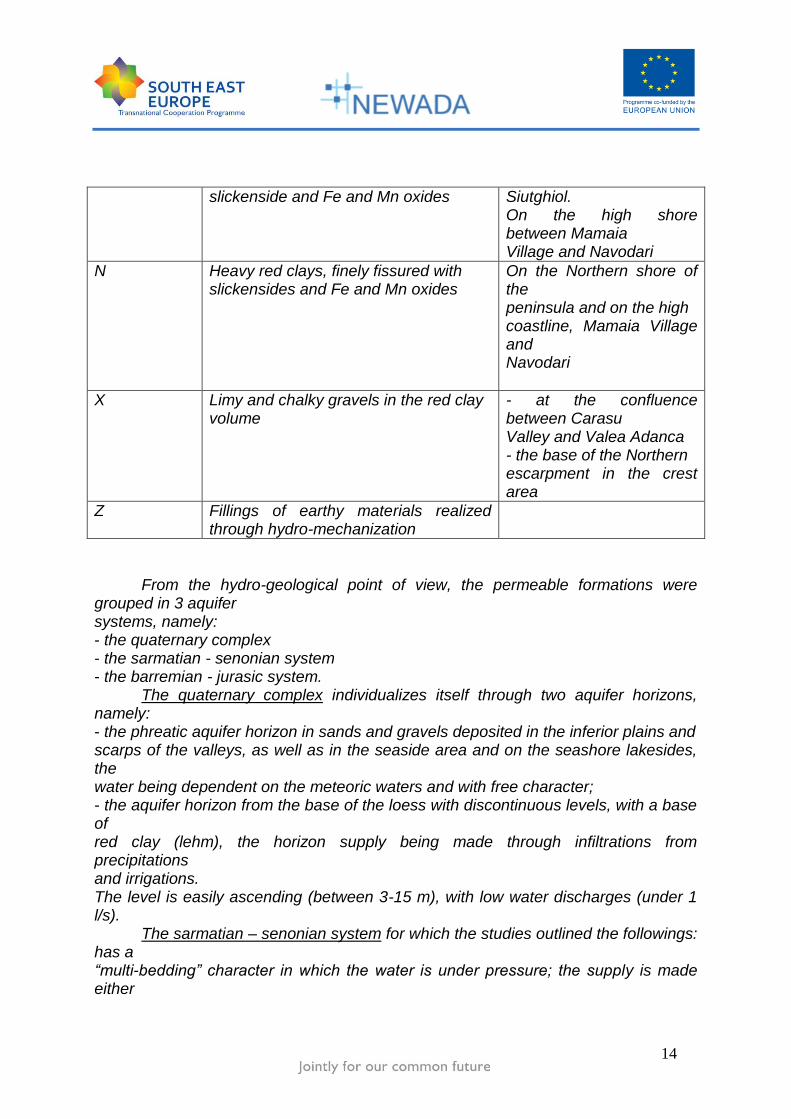
slickenside and Fe and Mn oxides
Siutghiol. On the high shore between Mamaia Village and Navodari
N Heavy red clays, finely fissured with slickensides and Fe and Mn oxides
On the Northern shore of the peninsula and on the high coastline, Mamaia Village and Navodari
X Limy and chalky gravels in the red clay volume
- at the confluence between Carasu Valley and Valea Adanca - the base of the Northern escarpment in the crest area
Z Fillings of earthy materials realized through hydro-mechanization
From the hydro-geological point of view, the permeable formations were grouped in 3 aquifer systems, namely: - the quaternary complex - the sarmatian - senonian system - the barremian - jurasic system.
The quaternary complex individualizes itself through two aquifer horizons, namely: - the phreatic aquifer horizon in sands and gravels deposited in the inferior plains and scarps of the valleys, as well as in the seaside area and on the seashore lakesides, the water being dependent on the meteoric waters and with free character; - the aquifer horizon from the base of the loess with discontinuous levels, with a base of red clay (lehm), the horizon supply being made through infiltrations from precipitations and irrigations. The level is easily ascending (between 3-15 m), with low water discharges (under 1 l/s).
The sarmatian – senonian system for which the studies outlined the followings: has a “multi-bedding” character in which the water is under pressure; the supply is made either

15
descendant through the surface infiltrations or the drainage of the quaternary aquifer, either ascendant through drainage. For Poarta Alba – Midia Navodari canal this aquifer system includes only the senonian chalks for which the ISPIF and ISPH studies remark: - the permeability coefficient is between 0.1 and 30-50 m/day; - the water discharges in the strongly fissured areas are between 0.3 and 1.4 mc/s/100 m canal.
The barremian – jurasic system is the most important in Southern Dobrogea, both for the development and for the exploitable water discharges. This system includes barremian limestone, nodulized valangenian limestone, as well as siliceous, conglomerated, arenaceous and magnesium limestone jurasic aged. The water from this system is under pressure, the supply being made through a fissures and karsts network developed through the surface infiltrations where the jurasic formations appear daily. On the basis of the available data, in the table below it is presented a brief hydro-geologic characterization on the line of Poarta Alba – Midia Navodari canal.
Km 0-2 Quaternary NH, free level at +5.0 m
Km 2-7 Quaternary NH, level 12-23 m
Km 7-11 Quaternary NH, free level at 20.0 m
Km 11-16 NH around the level 10-12 m with a descending tendency towards East and West - Jurasic
Km 16-Black Sea Quaternary NH, free level at 2.5 - 2.7 m West and 0.7 – 1.5 m East

16
LONGITUDINALE PROFILE OF POARTA ALBA-MIDIA NAVODARI CANAL
B.3.3. WORKS ALONG THE PAMNC(PARAMETERS)
B.3.3.1. LOCKS – two twin pieces at Ovidiu (km 12 + 255) and Navodari (km 2 + 120), with the
following main characteristics: ----------------------------------------------------------------------------------------------------------------- Specification Ovidiu Navodari -------------------------------------------------------------------------------------- - useful length of the lock chamber (m) 145 145 - useful width of the lock chamber (m) 12,5 12,5 - miter sill’s foundation depth:
Upstream : - minimum level 5,00 5,25 - maximum level 6,50 6,50
downstream : - minimum level 5,25 4,90 - maximum level 6,50 6,50
- crest cote (mrMB) 11,0 4,50 - lock chamber floor cote (mrMB) - 4,25 - 6,50 -----------------------------------------------------------------------------------------------------------------

17
The locks are dimensioned for a navigational traffic 20 millions tones/year. The functioning system of the locks is of about 300 days/year, each.
B.3.3.2. PORTS AND MOORING POINTS ---------------------------------------------------------------------------------------- Ovidiu Port Luminita Port Specification Km 10 + 100 km 0 ---------------------------------------------------------------------------------------- - operating capacity (mil. t / an) 3,2 5,6 - levels:
Minimum (mrMB) 1,25 1,25 Maximum (mrMB) 2,00 2,00
- bottom basin level (mrMB) - 4,25 - 4,25 - crest cote (mrMB) 4,50 4,50 - operating area ( m ) 400 225 ----------------------------------------------------------------------------------------------------------------- The navigation on the PAMNC is made for merchandise transport: with fluvial vessels, fluvial - maritime self propelled vessels, small unpropelled vessels, in pushed or couple convoy, which subscribe the following gauges:
- Maximum length = 119,4 m - Maximum width = 11,4 m - Current draft = 3,8 m - maximum admitted draft = 4,5 m ( at maximum speed of 6 km/h ) - maximum navigational speed = 10 km /h
B.3.3.3. ADJACENTS WORKS that ensure the functioning of the waterways, in the limits provided by the
satisfaction of all uses are: - Roads and bridges, placed on both banks at cote +10 mrMB; - Telecommunication installations and informational flow; - Equipment for the informational system of water management; - An exploitation fleet; - A signaling system for navigation and other activities.
18
C. WATERWAYS MAINTENANCE
C.1. MAIN ACTIVITIES FOR WATERWAY MAINTENANCE –HIDROLOGY, SURVEY, SIGNALIZATION
C.1.1 HYDROLOGY(GENERAL INFORMATIONS)
C.1.1.1. HYDRO-METEOROLOGICAL PARAMETERS
According to the initial project of the navigable canals DBS and PAMN there was a system for speed and wind direction measurement, of temperature and rainfall measurement but the system did not work because of the low flexibility of the equipments.
Presently on the navigable canals there is no hydro-meteorological station for collecting the hydrological parameters.
The project Data system of hydro-meteorological parameters was created which consisted of:
- Fixed stations for measuring the hydro-meteorological parameters (speed and direction of the wind, the nature and quantity of rainfalls, visibility, air temperature and water in the canal temperature);
- Data transmission equipment at the central dispatch in Agigea and at the other dispatches in the area;
- Equipment for processing and display of the transmitted data for the local stations.
The hydro-meteorological parameters will be public. C.1.1.2. HYDROLOGICAL PARAMETERS
The information regarding the water level and flow on the Danube, the forecast of the level evolution is collected daily from the site of the National Institute of Hydrology and Water Management. At Administration of Navigable Canals S.H. there is a data basis serving this purpose. Installations for measuring the levels, the flows and the water volumes The level measurements on the navigable canals are made through installations of level measurements completely automated and assisted of existing computers at the four locks. The level measurement system allows the transmission at the Agigea Central Dispatch in a computer, where it will be created a data basis regarding the history of the level variation in the two waterways.

19
In addition to this, in all the hydro-technical nodes there are located topometry gauges for comparison and as reserve element at the automated installations. Along the canal, on one and the other side of the canal there are observation drillings, summing up to a 30 pieces on Danube – Black Sea Canal and 12 on the Poarta Alba – Midia Navodari Canal. The measurement system accomplishes the following conditions:
- Measured parameter: the water level in the downstream points and upstream ones on each lock;
- The level measurements precision: ± 1 cm; - Level display frequency:
- Locally at lockage: - from 5 to 5 minutes - The transmission to headquarter: - once an hour;
- Data base: in the computer from the headquarter is created a data base with statistic role which covers the transmitted data from the level measurements installations;
- Environmental requests: the installation functions no matter what season, including the case of ice on the canal.
The water flows and volumes taken from the Danube, transited on the DBSC
and PAMNC and evacuated in the Black Sea are calculated, registered and centralized daily within the office of water management, where there is a data basis in this purpose, based on the reports transmitted from the locks and the Complex Pumping Station Cernavoda.
C.1.2. RIVER BED MEASUREMENTS(GENERAL INFORMATIONS)
The maintenance of fairway suppose to maintain the wet section of the canals in limits of the designed parameters through periodic dredging of alluvial material deposits by water taken from the Danube and rising from hidrographic basin. In The Rules of operation and maintenance of navigable canals are included articles regarding dredging works, which will be executed in order to maintain the wet section of canals between the designed parameters. Dredging periods will be established so that solid deposits on the bottom of canals does not exceed thickness of 1 m ... max 1.25 m for the Danube Black Sea Canal and 0,75 m ... max 1 m for Poarta Alba-Midia Navodari Canal. In these line, ACN performs regulary hidrographical measurements , check the channel section, especially the fairway in junction area of the canal wih Danube River and the entire route, including the attachament areas of the tributary valleys to the canals. Hydrographic measurements is essential to be realised at least once a year, completely on both canals, and in critical points, where are solid deposits, whenever is necessary. During the dredging period the measurements has to be realised every month.

20
Responsible for this activity is ACN through Measurement-UCC office. Data from hydrographic measurements are used to:
- Determining the volume of water - Determine the necessary volume for dredging /dredging reported in report
with a project level - By comparison with previous measurements (systematic measurements) we can track deposits areas and areas with erosion and can be estimated volume and length of them - If a statistical set of successive measurements is available it can be adopt different models of prediction
Acquisition and data processing The coordinate system used is ellipsoidal geographic coordinate system WGS 84. The advantages by using this sistem is: - Portability of geographic data (import-export facilities in various GIS platforms, exchange information with hydrographic autorities, design and research institutes from the country and from abroad - Possibility of making repeated measurements on the same routes for systematic tracking of the evolution of land covered by water - Minimum error in processing - Low costs of production (does not require network support are local-global coordinates) Defining of the land line breaks In order to carry out hydrographic measurements and digital maps it is necessary to be determined ,first,the line of land and main constructions (the quays corners, the limits of dams, buildings, signs and others) Sailing Routes On the digital map containing land line it is indicated: navigation routes (the limits of proposed dredging area) for collecting hydrographic datas. Navigation routes have to form a rectangular grid with constant step. In the network nodes it will be verified the accuracy of the depth measured by ultrasound. Density routes will be chosen depending on future design needs. For a detailed edification the recommended equidistance is between 5-10 m and for a large areas edification with relatively linear bottom configuration is recommended an equidistance between 25-100 m.
21
In present, in ACN hydrographic measurements are runing by a motor boat equipped with the following equipment: - ecosounder transducer mount on the boat, sank at least 30 cm into the water; - WADGPS antenna mounted on the vertical transducer; - Ecosonda and WADGPS receiver for real time transmission of the position / depth to a PC unit ; -Portable computer whereupon is coupled the transducer and GPS; -Navigation and online data acquisition program; ACN is developing a project of implementation for a complete hydrographic measurements system on navigable canals. The system includes two components:
- A relatively small vessel size (length 15 to 16 m, width 5m, 1 m maximum depth, autonomy for 10 hours). On the main deck of the ship it will be located a control cabin and a cabin for measuring work activity;
- - A group of equipments and softwares necessary to manage the informations submitted by the equipments, the processing of them , the calculation of water and dredged materials volums, processing the datas.
The set contains the following components: -hydroacoustic system for depth measuring ; -hydroacoustic system for profiling the layers of sediments; - accurately positioning system; - motion sensors; - processing unit with the necessary programs, software programs necessary
for the preparation and execution of hydroacoustic research; -programs required for final processing.
C.1.3. BOTTLENECKS
The main bottleneck on the waterways administrated by ACN is the confluence of the Danube river with Danube -Black Sea Canal, because of solid deposits accumulated on bottom of the canal, in this area. In accordance with the existing studies, solid flow considered initially that will be seek on the bottom is about 340.000 cubic meters per year wherefrom 200.000 cubic meters per year is coming from suspension in water taken from the Danube and filed the first part of the canals and 140.000 cubic meters per year is coming from the tributary valleys and deposited into the canal,in connection area with these valleys. Due to the hydrological state of the Danube, the carrying silt and inclusiv of morphological characteristics of the Danube at the confluence with the canal was
22
changed, so that in the area has been a continuous process of accumulation of deposits, including on the I stream . At this moment the only solution is dredging.
Dredging works are realised by keeping traffic open at least one way of navigation with corresponding signalization. The navigation dispatcher of ACN has the responsability to comunicate to each skipper, the existing dredging works and its position. Performer is announced by radio, for the ship or convoy departure time and about the time it arrives in the area. The navigation dispatcher of ACN has the responsability to notify the seafarers, by notification, all changes on sailing conditions. Taking into acount the hidrographic measurements that was realised last years by ACN , for the next 3 years are estimated to be dredged about 500,000 cubic meters per year. For the sediments dredging from the inland waterways can be used in on acceptable economic terms, the following :
-ladder dredger -absorbent dredger -dredger with cranes or floating cranes equipped with claw -Mobile cranes equipped with claw, located on the pontoon crane -ballast dredger The executor can use any other equipments, by keeping the conditions
imposed by „Dredging technology on the navigable canals“. In the water,oil or gas pipes area and the related slopes area will be not use absorbent dredger. The executor can do the dredging works with other types of equipments, only with the approval of the general designer of the waterways. We present below some of the characteristics of dredging machines built in Romania. Ladder dredger features: Productivity: 750mc Dimensions: length-65 m, width = 11.50 m Maximum depth of dredging-22 m Minimum depth of dredging-8m Dredging-capacity of 750 m³ / h Floating crane features: Length-27.40 M width- 16, 00 m The hook-loading - maximum 10 tonnes Lifting height from water level-20 m Underwater immersion level -8 m Maximum opening of arm -27 m Minimum opening arm -8m

23
Absorbent dredger Lungime- 25- 30 m, width = 17.00 m Maximum depth of dredging-8, 00 m Minimum depth of dredging-2, 50 m
Another categorys of bottlenecks on Danube- Black Sea Canal and Poarta Alba-Midia Navodari canal are the locks Cernavoda, Agigea, Ovidiu and Navodari, because of the potential interruption of navigation by the failure of hydro-mechanical equipmentand because of their expired lifetime. Maintenance works at the locks will be presented in Chapter 8 of this report-Planning for lock maintenance and repairing. In present it is on going a feasibility study related the modernization of the locks equipments , financed by ISPA founds.
C.1.4. SIGNALIZATIONS
The signalling from the waterways requires static and light signalling of the
waterway banks.
Static signs include panels with permanent significance, which provides informations regarding: the miles, working VHF channel navigation area, fixed obstacles along the canals, pipeline or power line crossings. This information is provided by indication signs, restriction signs, prohibition signs, obligation signs and all concures to the navigation in safety conditions during the day.
Now,these signals are almost nonexistent on both sides of the canals because of the degradation over time, thefts and damages. Light signalling concure for sailing in safely conditions during the night , and requires light signals for banks , bridges, the confluence of Danube-Black-Sea canal with Poarta Alba Midia Navodari canal, the entrance and exit from ports, locks and canals. In present,there are locks signaling installations, bridge signals, with their life time expired and some of them are not in function. The beacons which means coast signals ,are functioning in a very small percent, and signals for entrance/exit from canals are totally damaged.
ACN will modernize the signaling system through a project financed by European Funds through Sectorial Operational Program for Transport. The project consists in modernization both the light signalling and static signaling with the following elements:
- Light signaling of the banks

24
- Light signaling of bifurcations - Joint light signaling of bridges (static and light) - Light signaling of ports - Directional light signaling (entrance and exit from the canals) - Passive signaling.
Effective, the works for modernization of the signaling sistem will be located along the technological road along the canal (above the wet section of the canals),on the bridges that crossing the canals, at the entrance and exit to ports, on the bifurcation of Poarta Alba-Midia Navodari canals with the Danube-Black Sea canal.
Anchoring and standing of ships / convoys in other places than the specially designated for is prohibited. Standing is allowed only with approval of the ACN and in the conditions specified by the ACN. It is prohibited to anchor ships / convoys in pipes crossing areas and tributary valleys area.
C.2. REPORT FOR RIVER ENGINEERING CONSTRUCTIONS AND EXECUTION
C.2.1. DANUBE BLACK SEA CANAL
C.2.1.1. WATERWAY
Main branch, emerges from the Danube in the right locality Cernavoda, 0+000 km (navigation)and discharge into the Black Sea, north of Agigea town,64+410 km (navigation) in Constantza South Harbour. Danube-Black Sea Canal includes three distinct areas: - First sector situated between the Danube and the twin locks from Cernavoda, with a length of 4,10 km. - Second sector situated between the twin locks from Cernavoda and Agigea, with a length of 58,30 km. - Third sector situated between the twin locks from Agigea and the sea, with a length of 1,81 km.
For location and achieve the junction mouth of the canal and the link with the Danube fairway were prepared research and model studies that have shown: - in the confluence area of the canal with bed of the Danube River and I sector alluvial deposits occur, due first to the reduction of water current velocity in the area; -the volume of silts, estimated on the basis of radiometric measurements on the model, has maximum values in the area of connection of the canal with bed of the river and on the first 500 meters of the waterway. - to maintain the depth needed in this area and to ensure water in the Danube riverbed and canal sector I , periodic dredgings are required.

25
The volume of deposits in the mouth of the waterway access was assessed according to studies and research on models made from 200 thousand cubic meters per year of which 35 thousand cubic meters in the upstream canal.
Danube - Black Sea Canal has become operational in 1984. Due to the hydrological regime of the Danube, riverine transport and morphological characteristics of the course of the Danube at the confluence of the canal, the area has been a continuous process of accumulation of alluvial deposits in the right side of the Danube riverbed and I sector canal including shunt canal.
Regarding the maintenance of the canal section to make the parameters, the "Rules of operation and maintenance of the Danube - Black Sea Canal" provided that regular dredging of alluvial material by Danube waters should be done such that it does not accept deposits of silts on the bottom of the canal more than 1 meter thick. The Danube water levels of the "+ 50 cm" at Cernavoda can not surf the convoys 'conventional type of 6 barges x 3000 t'; is needed their reformation in convoys less than 2 or 4 units or barges to be loaded below capacity to have a smaller draft. However there is still a serious situation, namely, the migration of silts from sector I to sector II where local deposits occurred where the vegetation is growing. To this respect, run periodically dredging works like this: - in the bed of the Danube to achieve fairway linking the two waterways. - in the fairway sector I for recover it and restoration of the canal section, at the parameters required for taking water flows projected for all land use. - on the bypass canal, to remove silt deposits and stopping the migration from sector I in sector II .
C.2.1.2. RIVER BANKS
The stability of the the channel section is provided by the defense and consolidation works of which types were determined in execution projects. The protection works of slopes against mechanical action caused by waves and erosion caused by rainwaters and / or groundwaters, are differentiated and have been designed taking into account the terms of geomorphological, geotechnical and hydrogeological characteristics of each area. The works for stability section, the defense and protection of the Danube-Black Sea Canal slopes includes:
The works under the service road level contains: • slopes defense works applied on bank slopes (1:3; 1:4,5), made in clay and clay powder dust (fascine works, wedges of raw stone, rok riprap on converse filter); • defense and protection works made in spoiled chalks and limestones( built riprap); • above the area of wave action, mattress prefab; • Along the the crossing area of the city Medgidia, where the slopes are vertical the solutions was with walls appplied in open caissons, curved masonry walls; • on the plateau area, in the wetted section were applied the solutions with retaining
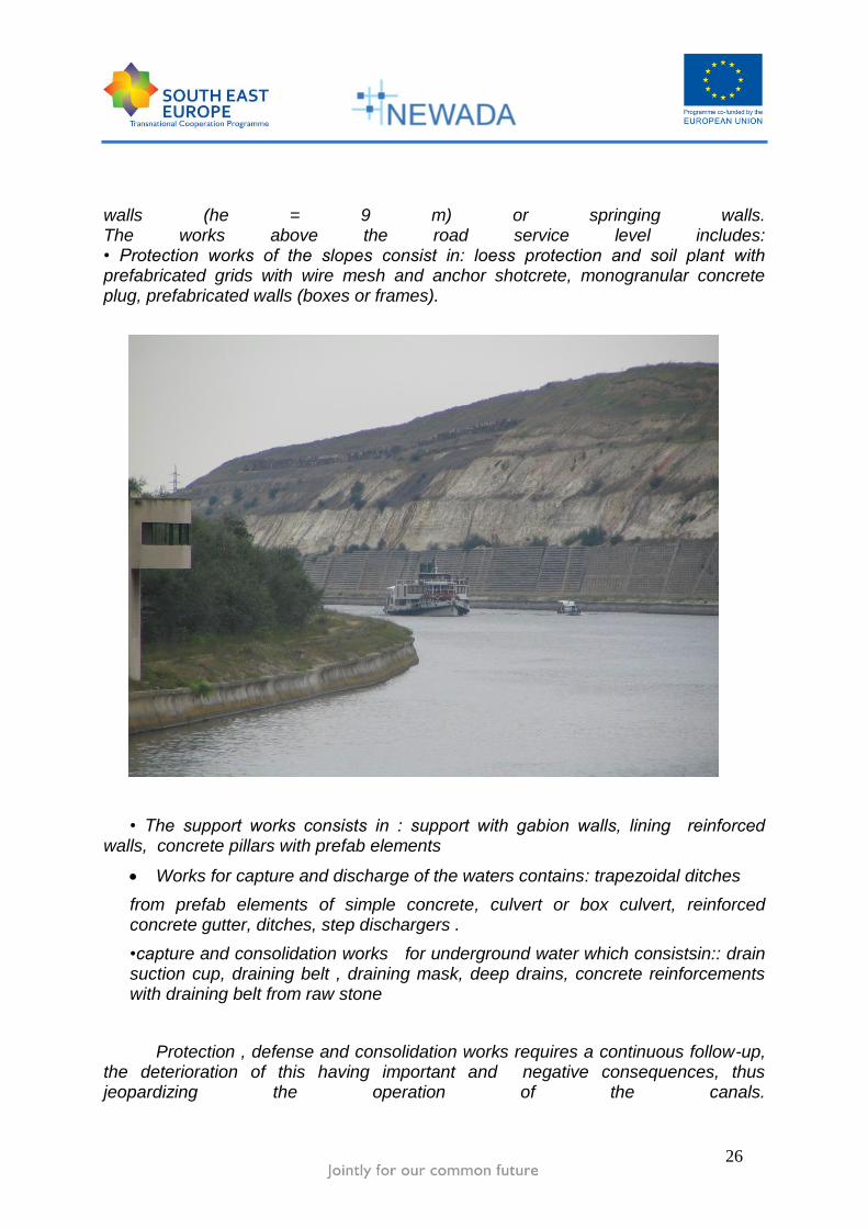
26
walls (he = 9 m) or springing walls. The works above the road service level includes: • Protection works of the slopes consist in: loess protection and soil plant with prefabricated grids with wire mesh and anchor shotcrete, monogranular concrete plug, prefabricated walls (boxes or frames).
• The support works consists in : support with gabion walls, lining reinforced walls, concrete pillars with prefab elements
Works for capture and discharge of the waters contains: trapezoidal ditches
from prefab elements of simple concrete, culvert or box culvert, reinforced concrete gutter, ditches, step dischargers .
•capture and consolidation works for underground water which consistsin:: drain suction cup, draining belt , draining mask, deep drains, concrete reinforcements with draining belt from raw stone
Protection , defense and consolidation works requires a continuous follow-up, the deterioration of this having important and negative consequences, thus jeopardizing the operation of the canals.

27
The influencing factors for the operation and maintenance of protection, defense and consolidation works,:
a) action of hydrodynamic forces arising from reduction of the underwater pressure against the water level from the canal put in joepardy the stability of the slopes. b) the defense and consolidation works from the wetted sections was not designed to resist on high wvariations of the water level from the canal. In exceptional circumstances may be discharged the water from the canal by decreasing slowly the water level
c) waves actions caused by wind and movement of ships and convoys with speeds more than 12 km / h (speed allowed by the rules of navigation).
d) Action phenomenos generated by the relationship between moving vessels and convoys , such as propeller jet and reverse current, acting on the bottom of the canal.
e) direct mechanical actions produced by the ships, convoys or ice floes by shock, by decreasing the water level after ice period , and the anchorage of ships.
Taking into account of what was mentioned above, results that for maintain the defense and consolidation works in good function is prohibited:
- sharp drop of the water level into the canal or completely discharge of it;
- Circulation of the water between the canals sections (pools) to be realised in a controlled way., regarding the levels, flows and depths
-Navigation on the canal sth speed that not exceed 12 km / h;
- Filling and evacuation of the locks in less time than that was provided in the operation rules
- Anchoring of vessels and convoys according the navigation rules , avoid the trailling of chains or cables on the bottom of the canal
The adnnistration of the navigable canals must follow-up the technical status of the defense works to assign the areas were was observed damages, degradations or failure that may have significant negative influences on the entire stability of the canals slopes .
28
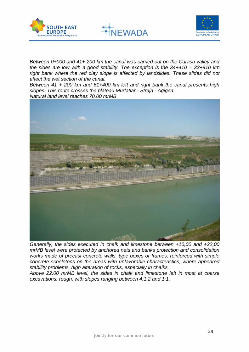
Between 0+000 and 41+ 200 km the canal was carried out on the Carasu valley and the sides are low with a good stability. The exception is the 34+410 – 33+910 km right bank where the red clay slope is affected by landslides. These slides did not affect the wet section of the canal. Between 41 + 200 km and 61+400 km left and right bank the canal presents high slopes. This route crosses the plateau Murfatlar - Straja - Agigea. Natural land level reaches 70.00 mrMB.
Generally, the sides executed in chalk and limestone between +10,00 and +22,00 mrMB level were protected by anchored nets and banks protection and consolidation works made of precast concrete walls, type boxes or frames, reinforced with simple concrete scheletons on the areas with unfavorable characteristics, where appeared stability problems, high alteration of rocks, especially in chalks. Above 22.00 mrMB level, the sides in chalk and limestone left in most at coarse excavations, rough, with slopes ranging between 4:1,2 and 1:1.
29
Works building failure and the lack of necessary funds to achieve all designed works have led to the situation as the gradual action of atmospheric factors and groundwater to be affected the stability of high slopes, especially on areas with red clay, but also on areas with chalk and limestone damaged, cracked and wetted.

30
Between the km 41 +200 to km 61 +400 on the plateau, from the natural land level(+70,00 mrMB) above chalk and limestone slopes meet lands of clay which in the majority were drained, finished and protected with grassing or plantations. In these lands is manifested instability phenomena, which in some sectors have given rise to massive land slides that have resulted, if red clays, volumes of material on lower levels, reaching in some cases operating on the road to + 10.00 mrMB level and even in the canal. Currently, the sides affected by the landslides have been strengthened and the material fell in the canal (6+ 500 km) was evacuated.

31
C.2.1.3. PORTS AREA
MEDGIDIA PORT AREA
The Medgidia port is located on the right bank of the canal from km 37 900 (26 510 km) *, is an integral part of the Danube-Black Sea and has a capacity of 11.5 million tonnes of traffic. Water levels in the port are the same as the channel namely: • normal operating: + 7.50 mrMB;
• minimum operating: +7,00 mrMB;
• minimum exceptional level : +6,00 mr MB;
maximum operating level +8.50 mrMB.
The level of the ports platform is +11.0 mrMB . The crest level of the waiting berths :

32
Upstream : +10,00 mrMB
Down stream : +11.00 mrMB
-The ports industrial activity includes:
Berths for limestone - 800 m on the southern side and 120 m on the east side for cement shipments, two berthsin length of 400 m on the central mole and a berth of 120 m on the east side.
The commercial activity developes as following:
- 500 m berths for receiving/dispatching of general goods;
- A berth of 140 m for technical vessels;
- 120.33 m for a berth for supply.
Passenger transport activity is developing on passenger berth, located on the south side of the port having a length of 100 m.
The waiting activity , for dismantling/ remaking the convoys is developing on the 2 waiting berths located i , with the length of 600 m (Upstream) and 300 m (dowmstream), located in the entrance of the port.

33
BASARABI PORT AREA Basarabi port is located on the right bank of the canal from km 24 910 (39 500 km) * and has a traffic capacity of 0.7 million tons per year.
Hydrotechnical water regime in the port area is the same with the second pool of the Danube-Black Sea canal
- bottom level of the canal and ports basin: + 0.50 mrMB;
- The normal operating level: + 7.50 mrMB;
- Minimum operating level: + 6.00 mrMB;
- Maximum operation level : + 8.50 mrMB
- Higher level of construction and ports platforms : + 11.00 mrMB
34
In Basarabi port are developing the following activities:
• provide supply services at the request of vessels, loading and unloading aggregate, coke, gypsum • loading and unloading barges
C.2.1.4. PROJECTS ALREADY DONE( 2001 – 2009 period ) :
- Maintenance and reparation of the locks equipment - Dredging works ( 2.000.000 mc) in first section of canal :
km 0+000 – 4+100 ( L = 4.100 km )
- Works of bank protection and consolidation
Right bank:
- Murfatlar Plateau area : km 23+087 – 21+584 ( L= 1.503 km) - Straja – Agigea Plateau area: km 7+110 – 6+410 ( L= 0.700 km)
km 4+ 910 – 4+110 ( L= 0.800 km)

35
C.2.1.5. PROJECTS IN EXECUTION :
- Maintenance and reparation of the locks equipment - Dredging works in first section of canal - Works of bank protection and consolidation
Right bank:
- Murfatlar Plateau area : km 21+584 – 21+237 ( L= 0,347 km) - Straja – Agigea Plateau area: km 6+910 – 6+710 ( L= 0.200 km)
C.2.2. POARTA ALBA MIDIA NAVODARI CANAL
C.2.2.1. WATERWAY
PAMNC emerges from the Danube - Black Sea, at 29+760 km on CDMN and
discharge in the sea through the port MIdia, with a direct link with Lake
Navodari (Tasaul) to limestone quarry, where was made the Luminita Port.
The canall has three characteristic areas:
- First Sector I located between CDMN and the twin locks from Ovidiu km 0 to
15+230 with L = 15,230 kilometers.
- Second sector located between the twin locks from Ovidiu and Navodari, 15
km from 230 to 25+450 with L = 10,22 kilometers
- Third sector located between the twin locks from Navodari and the Black Sea with L = 2,05 kilometers
C.2.2.2. RIVER BANKS
The stability of the canals section is provided by the defense and consolidation works which types were determined in executions projects.
The defense and protection of the slopes against the mechanical action caused by waves and erosion caused by rainwater discharges and / or groundwater, are differentiated on the Valea Adanca area and on the crossing area of Siutghiol and Tasaul lakes and was designed taking into account the terms of geomorphological, geotechnical and hydrogeological characteristics from this areas.. In the wetted section the works consists in fascine mattresses and riprap of raw stone on converse filter and in the areas with prone slopes and retaining walls in the areas with vertical slopes.

36
Above the wetted section have been provided works for capture, draining and discharging the underwarter , reinforced ditches water dischargers, , consolidations works with draining masks, and draining belts, , protections with loess and soil plant .

37

38
Along with the ceasing of works after 1990, the vertical embankments of limestone above the level of exploitation road +10,00 mrMB, both on the left bank and right bank, mainly on the ridge area km 15+500 -12+680, were left to level of coarse excavation between +10,00 mrMB and +38,00 mrMB levels. The unprotected rocks from the embankment are exposed to a continuous degradation action by the separation of blocks up to 2 t / each, which fall and block the road platform from +10,00 level, the often reaching in the canal. Above level+ 38,00 mrMB the embankments are strengthened and protected by drainage and protection works but because of the exfiltrations and the heavy rains in this area meet ravins and landfalls that have clogged and blocked +10,00 mrMB level. The natural land level in this area is +65,00 mrMB. Between 11+000km and 3+000km, the trench canal height is reduced, and the embankments are generally steady. The company allocates each year significant funds for maintenance of navigable canals, as follows: - Ditches cleaning of alluvial material from the higher levels and road operation cleaning +10,00 mrMB to avoid silting the canal.
C.2.2.3. PORTS AREA
For PAMNC were designed two ports on the canal, at km 11 000 (16 500 km) *, in Ovidiu, on the right bank and another to Luminita, in Lake Tasaul. At the exit of the canal into the Balck Sea was designed Midia port which contains a river-maritime sector representing a separate investment which is operated and maintained by separate rules.The Midia port is not in administration of the ACN.
Both ports have industrial character and developing activities consists in :
• dispatch of dolomite and limestone
dispatch of stone and sand for constructions
• storage and export of metal
Operation of the ports in the line of approved parametres is influenced by:
Levels very high and very low of thw waters in section 1 and II of the canals
very low temperatures (below-120C) which can lead to ice bridges in the river port, in ice period
convoys that can lead to blocking the entrance into the port ;
winds with speeds exceeding 10 m / s.
39
OVIDIU PORT
Ovidiu port consists of:
- A quay length of 300 ml –vertical type quay
- - A quay length of 200 ml – weight vertical quay
- Waiting berth with a length of 400 m – riprap quay
LUMINITA PORT Luminita port is composed of:
- Two quays L = 140 m each – vertical type quay - Waiting berth of 285 m – riprap quay
The berths must be equipped with bolarzi, access steps, rubber bumpers, and facilities that allow the anchoring of vessels. The lifting and transport installations are provided by the beneficiars.
C.2.2.4. PROJECTS ALREADY DONE ( 2001 – 2009 period ) :
- Works of bank protection and consolidation:
Right bank:
- Ovidiu Plateau area : Km 16+000 – 15+000 ( L= 1,000 km ) The works are made between natural land level (+70,00 mrMB) and +10,00 mrMB level. The works collect surface waters from right bank and discharge them in canal, also the bank protection works will halt the phenomenon of slope degradation.
C.2.2.5. PROJECTS IN EXECUTION
- Works of bank protection and consolidation:
Right bank: - Ovidiu Plateau area : Km 15+000 – 14+500 ( L= 0,500 km ) In present it is on going a feasibility study financed by ISPA founds. This project is part of a global project regarding the navigation on the Danube concerning the improvement of the Pan-European Corridor no. VII since its aim is the improvement of the navigation conditions on the Danube, thereby it will

40
answer to all the necessities of the transport national policy in Romania as well as to all the international commitments of the countries. In order to satisfy these requests, the project includes in the section III namely Section III: Danube – Black Sea Canal and Poarta Alba – Midia Navodari Canal, a feasibility study, for the stability and erosion problems regarding the superior banks of the Canal, and the modernizations of the canal locks and installations. . C.2.3. COMMON SECTOR, WATERWAY MAINTENANCE
Due to the geographical position of the navigable canals Danube-Black Sea and Poarta Alba-Midia Navodari we have no common areas with other waterways administrations. The only contact area with other waterway administration is the confluence of the Danube river with Danube Black Sea Canal. In this section, Danube rib\ver is in administration of AFDJ.
C.2.4. WATERWAY MAINTENANCE IN THE ICE PERIOD
In winter, with ice from the shore and ice floats, the navigation run its course only with ships authorized to navigate in such conditions through ice-floats and only with ACN permission.
Supposing on the canals is formed ice bridges or large floats, navigation is restricted in part or complete. Administration may prevent and create a permanently maintained fairway with a maximum width of 30 m and meeting places for ships / convoys (ports, bifurcations).
In case of unfavorable hydrometeorological conditions, or when from other causes navigation on the canal is threatened, ACN may decide the temporary closure of navigation through canals, and inform the skippers about the unexpected modifications, by notice. From tehnical point of view for the equipments of the locsks is not recommended to function below a temperature of -12*C
C.2.5. WATERWAY MAINTENANCE IN THE LOWEST LEVEL PERIOD
Danube-Black Sea Canal was designed as the operating water level in the canal side between the confluence of the Danube river with Danube -Black Sea canal to Cernavoda lock to be the same as in the Danube river . So, in periods of low water when the level drops, the navigation in this canal side run its course with the same restrictions as the Danube river.

41
C.2.6. WATERWAY MAINTENANCE IN THE HIGHEST LEVEL PERIOD
Waterways have been designed so that, the flood of rains in the catchment area to be evacuated to the sea through exhaustion gallery for high water level. In case of a water floods, the gallery are operated automatically or to order. When the necessary exhaust flow exceed the level which was designed the gallery, the excess will be discharged through the exhaustion gallery of the locks, which will be stop operate for the lock activity. In the same time the navigable canals was designed with functions of receiver and discharger for the waters generated by rainfalls in the catchment area . The defense of the bordering cities of the navigable canals against waterflood caused by water retained in the canals is provided by the dams that were built on both sides of the canals in the lower areas. For defense against flood of the bordering cities there are provided 3 pumping stations and a gravity discharge. The hydrotechnic scheme of defense system of cities against flood provides a drainage system which with pumping stations assistance discharge the water into the II stream The maintenance of water levels and flow is achieved by levels measuring system, automaticaly to all locks.
In periods of high water (13 mrMB in I stream of Danube-Black Sea canal), or
rainlessness (2.75 mrMB in I stream – Danube-Black Sea canal), "The Operation Scheme of Navigable Canals” enter in alertness and is coordinated in colaboration with other authorities. Because the hidrotechnical scheme of both canals was designed to perform the role of regulation of leakages from its catchment area and defense role against waterfloods, during periods of flood or rainlessness there are no problems for beneficiaries, outside those created by the Danube river. C.2.7. REPORT ABOUT THE PREVENTION AND RESTORATION OF FLOOD DAMAGES
Regularization of the maximum drainage in the hydrographic basins and the transit of the floods through the navigable canals DBS and PAMN
1. The achievement of Danube-Black Sea Canal and Poarta Alba-Midia Navodari Canal with a complex hydro-technical scheme imposed the need to take some measures for the transit of the flow through the canals, so that the beneficial uses could function in the insurance limits admitted without being affected.
2. The hydrographic basins of the two navigable canals Danube-Black Sea and Poarta Alba-Midia Navodari, have a total surface of 939,8 km2 (including BH and Siutghiol = 12 km2).
42
The navigable canals have the function of receivers and evacuators of the waters, caused by the rainfalls in the afferent hydrographical basins.
This are taken over and assigned as follows: - Out of 36,6 km2 it is downloaded through canal pool I of DBSC, in the
Danube; - Out of 663 km2 it is downloaded in the canal pool II of the DBSC; - Out of 32,2 km2 it is downloaded through canal pool III of DBSC, in the
Black Sea; - Out of 154 km2 it is downloaded in the canal pool I of PAMNC; - Out of 42 km2 it is downloaded in the canal pool II of PAMNC; - Out of 12 km2 it is downloaded in BH Siutghiol. The affluent valleys of the waterways have a non-permanent drainage system
and a torrential character, fact which made necessary the defense against floods of the canal pool II of the Danube-Black Sea Canal and canal pool I of the Poarta Alba-Midia Navodari Canal, to achieve a number of 24 non-permanent accumulations, of attenuation and 10 accumulations for the retention of the wash. The equipment beneficiary – A.N. “Romanian Waters” Bucharest - Dobrogea Seashore Water Directorate Constanta ensures the operating. 3. The floods in the affluent valleys and the direct slopes affect the canal pool II of the Danube-Black Sea Canal and the canal pool I of the Poarta Alba-Midia Navodari Canal located between the twin locks of Cernavoda, Agigea and Ovidiu. For the draining of the floods the Navigable Canals accomplish the function of receiver and evacuator of big waters. Under these circumstances level growths are produced, with partial and temporary water accumulations in the canals section. Canal pool III through which it will be transited the same flows of water that originates from floods in the canal pool II doesn’t undergo special influences, because this being connected to the sea, allows the transit of floods without significant level modifications. 4. Affluent valleys are linked to the waterways through works that foresees the regularization of the valleys on the finishing sector and special constructions at the river mouth which reduces the transversal speeds in the downloading area until the admitted limit for navigation (0,3-0,4 m3/s) 5. The medium generalized rain with an insurance of 50% can be accumulated in the navigable canals with a surface of the normal level of operating it of about 0,20 m. The canals disposes of static capacities of accumulation in guard of 2,50 m over the normal level of exploitation of +7,50 mrMB, of 7,74 mil. m3 until the cote of +8,50 mrMB, of 15,77 mil. m3 until the cote of +9,50 mrMB and of 19,90 mil. m3 until the crest cote of the dam of +10mrMB. 6. At the Agigea locks the constructions which ensure the download to the sea of the flows that originate from the floods are Evacuating Galleries Big Waters, which regulate the maximum flows in the hydrographic sub-basin of the Danube – Black Sea Canal and the transit of the floods through the canal towards the Black Sea.
43
The evacuating galleries composed of evacuating outlet (siphoning batteries placed upstream), the constructions of enlargement (placed downstream), the discharger with clamshell (placed in the bodies of the hydro-electric stations), are dimensioned at the following flows:
- For the siphoning batteries = 2 pieces (one battery from 4 siphons each) – 150 mc/s x 2 pieces = 300 mc/s;
- Evacuating galleries; o In free leakage system = 150 x 2 = 300 mc/s; o In forced leakage system = 190 x 2 = 380 mc/s;
- Dischargers with clamshell = 2 pieces (40 mc/s x 2 pieces) = 80 mc/s ; - Hydro-electric stations (CHE) from Agigea - 75 mc/s x 2 pieces, a total of
150 mc/s installed capacity of 2 x 5 Mw, H = 8 - 7 m). 7. The floods produced by rainfalls, partially generalized (local) in the basins of
the affluent valleys, don’t create any particular problems even if these are subscribed in the level of insurance of calculus of 1% or of check of 0,3% or 0,1%.
8. The success of evacuating calculus floods from its check is conditioned by the existence of an information flow regarding the hydro-meteorological forecast in the hydrographic basin, as well as forecasting on the basis of a mathematical pattern of the start of activity of the whole complex of works which form the evacuating capacity of the flood towards the sea. In the periods of big waters (13 mrMB in canal pool I of the Danube – Black Sea Canal) or in draught (2,75 mrMB in canal pool I - Danube – Black Sea Canal), the “Scheme of Operating the Navigable Canals Danube – Black Sea and Poarta Alba – Midia Navodari” goes alert and is coordinated by an interdepartmental quarter. During freezing period the traffic on the canal is closed. The level of insurance is of 94%, according to the level of 2,94 mrMB (hydrological point) Cernavoda.
Defending the adjacent land of the waterways against floods As a consequence of the Danube – Black Sea Canal’s construction the normal level of exploitation of the water in the area located between km 4-18 with about 4 m (from the 3,5 at 7.5 mrMB) so that it was necessary to foresee defense works of some villages against floods, which are: Saligny – Stefan cel Mare, Faclia and Mircea Voda (railway station). The hydro-technical scheme of the defense system of the villages against floods foresees a draining system and pumping stations for downloading ground waters in the canal pool II of the Danube – Black Sea Canal.
For the defense against floods of Saligny – Stefan cel Mare, Faclia and Mircea Voda and Castelu villages there are 3 pumping stations foreseen which have the role of maintaining the low level of the ground water. Because the complex hydro-technical scheme of the Danube – Black Sea and Poarta Alba – Midia Navodari waterways is dimensioned to fulfill the purpose of regularization of the leakages in the own hydrographical basin and of defense

44
against floods during flood or drought periods there are not registered any particular problems with the beneficiaries of use besides those created by the level of the Danube. C.2.8. PLANNING FOR LOCK MAINTENANCE AND REPAIRING
C.2.8.1. RESPONSABILITY
The company locks management activities is in charge of Locks department ,
a structure coordinated by Technical Manager. The Locks Department has the main responsibilities to ensure the operation, maintenance and revision of the four locks namely Cernavoda, Agigea , Ovidiu , Navodari
.C.2.8.2. THE MAINTENANCE OF THE EQUIPMENTS AND
INSTALLATIONS AFFERENT TO THE NAVIGABLE CANALS The equipments and the installations afferent to the navigable canals DBSC and PAMNC are: a) Basic technological equipments (gates and valves of the locks, etc.); b) Adjacent equipments and installations (the energy supply of the installations, etc.); c) Equipments and installations for the safety of navigation and of the objective (signaling systems, installations for preventing fires, etc.); d) Equipments and installations for executing the maintenance works (box dam, pump stations for lock drainage, etc.) e) Equipments and installations for constant maintenance of the level in the navigational sailing line obstructed by the 2 locks (pumping stations, evacuating galleries of the big waters, flow over, etc.); f) Equipments and installations for protecting the local communities (drainage system of the water infiltration, etc.).
At all these equipments and installations the following maintenance works are made: 1. Technical revision – consists of the detailed check of the equipment or installation. With this opportunity there are made adjustments and there are replaced the used pieces. The works are usually made with own powers and do not involve the remove from use of the lock. 2. Accidental repairs – are repairs which are made when there is a fault observed at equipment which involves its removal from use and that of the lock. There are usually big works which involve the removal from use of the lock. The works are usually made with special companies specialized in this type of repairs. 3. Current repairs – there are planned repairs which are made on the equipments and have as main purpose the brought of the equipment at the initial parameters. As well, all the used components are replaced. Generally these types of works are executed with specialized companies and involve the removal from use of the lock.

45
4. Important repairs and modernizations – these are big repairs and have as goal making the installation or equipments last longer. These are executed at big time intervals, have a big execution period and significant costs.
Maintenance works on locks are made by company employers on the basis of Annual maintenance plan. Those woks consists in preventive maintenance works and corrective maintenance works
C.2.8.3. PLANNING THE MAINTENANCE WORKS OF THE
EQUIPMENTS AND INSTALLATIONS AFFERENT TO THE NAVIGABLE CANALS
Executing maintenance works at all the equipments and installations afferent to the waterways involve 2 main elements:
- High costs mainly due to the complexity of the equipments and their number;
- Executing works involves the removal from use of the lock, which influences the development of navigation in optimal conditions.
Due to these reasons the planning of the works is necessary and it is executed taking into consideration the following main terms:
- The resource volume which can be given for maintenance works; - The technical state of the equipments and installations; - The influence of the works on the developments of the navigation; - The maintenance of at least one navigational way through the functioning
locks so that it doesn’t stop the navigation on the canal; - The possibility to group the works in such a manner that the work volume
of repairing preparations is reduced. The planning is made for the next financial year and is updated every time it is
necessary. The works which involve big work volumes are planned to be followed in the next financial year. The planning of the works and their observation is made in the specialized departments of the company because all the equipments and installations are in its heritage or administration. During all the work the ship-owners and authorities are informed relating the following:
- On what lock is the navigation possible; - The navigational restrains (especially when works are executed at the
navigational channel).