Embed Size (px)
Citation preview

GRAUPNER GmbH & Co. KG * Henriettenstrasse 94-96 * 73230 Kirchheim/Teck www.graupner.de * www.tangent-modelltechnik.com
ELEKTROELEKTROELEKTROELEKTRO
Manual ID:0062171
GRAUPNER GmbH & Co. KG * Henriettenstrasse 94-96 * 73230 Kirchheim/Teck www.graupner.de * www.tangent-modelltechnik.com
2
Contents Preface. ........................................................................................................... 3
Kit contents .................................................................................................. 4 Technical Data ............................................................................................. 4 RC functions ................................................................................................ 4
Fuselage.......................................................................................................... 5
Installing the canopy retainer. ...................................................................... 6 Installing the all-flying tail-plane. .................................................................. 6 Vertical stabiliser and rudder........................................................................ 7 Wing Saddle................................................................................................. 8 Motor Instalation .......................................................................................... 8 Servo Mounting Tray.................................................................................... 9 Fuselage Control Linkages ........................................................................ 10
Wings............................................................................................................. 10
Wing joiner ................................................................................................. 10 Wing mounting. .......................................................................................... 10 Preparation of the wing servo mounts........................................................ 11 Wing control horns. .................................................................................... 12 Wing servo wiring....................................................................................... 12
Finishing ........................................................................................................ 13 Radio Control Equipment Installation. ........................................................... 13 Balancing & Adjusting.................................................................................... 14 First Flights. ................................................................................................... 16 Safety. ........................................................................................................... 17 Parts List. ...................................................................................................... 18
GRAUPNER GmbH & Co. KG * Henriettenstrasse 94-96 * 73230 Kirchheim/Teck www.graupner.de * www.tangent-modelltechnik.com
3
High Performance Model Glider KULT Champ is a development of the earlier KULT series. This latest design incorporates further uncompromising performance characteristics made possible by the Carbon-CHAMP-Edition. Key highlights of this design include; new cell structure of the wings and all control surfaces, re-dimensioned and lightweight ailerons and flaps, and class leading square Carbon Hybrid Tec wing joiner. This new Champ is not a Kult with go-faster stripes; it is clearly in the scope of F3J. The model is available both as a pure glider and an electric powered version: KULT Champ ARC # 41740 KULT Champ Elektro ARC # 41800 KULT Champ white/red # 41750 KULT Champ Elektro white/turquoise # 41810 KULT Champ Anopheles # 41755 KULT Champ Elektro Anopheles # 41855
Preface. Thank you for choosing the KULT Champ high performance model glider. We wish you much success and enjoyment with your new model. Your TANGENT model kit from the home of GRAUPNER represents a mature design and the product of many years experience in the manufacturing of high performance model aircraft. However, despite the most scrupulous quality control, small deviations may arise. We ask therefore that all parts be carefully inspected prior to undertaking any assembly work and before flying the model. This is particularly important as any used parts are not subject to repair or replacement. Notwithstanding the above, we are happy to repair or replace parts found to be faulty – subject to approval by the factory. Please therefore return any faulty parts together with a detailed description of the fault. Our products are the subject of continuous development and as such we reserve the right to make changes to the design, engineering, manufacture and materials supplied without prior notice. As the product is supplied in kit form, no claims will be considered in respect of the assembly or operation of the model. Caution! Remote controlled models and model aircraft in particular, are not toys in the normal sense. Building and operation of this model aircraft requires a high degree of technical understanding and care, as well as considerable skill and discipline at the flying field. Errors in the building process and in the subsequent operation of this product can result in serious personal injury and damage to property. As kit manufacturer we have no control over the assembly, maintenance and operation of this model aircraft, we therefore take this opportunity to stress the potential hazards and emphasise the personal responsibility on the part of the user.
GRAUPNER GmbH & Co. KG * Henriettenstrasse 94-96 * 73230 Kirchheim/Teck www.graupner.de * www.tangent-modelltechnik.com
4
Kit contents - (See Parts List for details) 1 Pair of wing panels – Carbon Champ Edition, incorporating LSCTP,
3D optimised leading edge & tip section, torsion-rigid INTRO Technology, integrated Elastik Flaps, square Carbon Hybrid wing joiner, TA Servo-Locks and TA wing locking system.
1 GRP Fuselage – in brilliant white, Carbon reinforced with built-in Bowden tubes. 1 Canopy - preformed in Carbon. 1 All flying tail plane – factory finished. 1 Rudder – factory finished. 1 Assembly instructions – sheet. 1 Decal set. 1 Wooden parts set. 1 Accessory pack – quality Contestline components. 1 Square wing joiner – Carbon Hybrid Tec 1 Wire parts set.
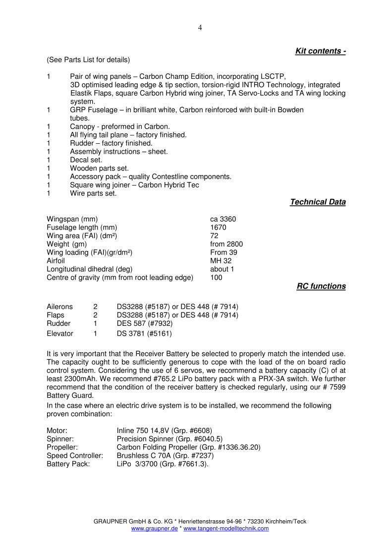
Technical Data Wingspan (mm) ca 3360 Fuselage length (mm) 1670 Wing area (FAI) (dm²) 72 Weight (gm) from 2800 Wing loading (FAI)(gr/dm²) From 39 Airfoil MH 32 Longitudinal dihedral (deg) about 1 Centre of gravity (mm from root leading edge) 100
RC functions
Ailerons 2 DS3288 (#5187) or DES 448 (# 7914) Flaps 2 DS3288 (#5187) or DES 448 (# 7914) Rudder 1 DES 587 (#7932)
Elevator 1 DS 3781 (#5161)
It is very important that the Receiver Battery be selected to properly match the intended use. The capacity ought to be sufficiently generous to cope with the load of the on board radio control system. Considering the use of 6 servos, we recommend a battery capacity (C) of at least 2300mAh. We recommend #765.2 LiPo battery pack with a PRX-3A switch. We further recommend that the condition of the receiver battery is checked regularly, using our # 7599 Battery Guard.
In the case where an electric drive system is to be installed, we recommend the following proven combination: Motor: Inline 750 14,8V (Grp. #6608) Spinner: Precision Spinner (Grp. #6040.5) Propeller: Carbon Folding Propeller (Grp. #1336.36.20) Speed Controller: Brushless C 70A (Grp. #7237) Battery Pack: LiPo 3/3700 (Grp. #7661.3).

GRAUPNER GmbH & Co. KG * Henriettenstrasse 94-96 * 73230 Kirchheim/Teck www.graupner.de * www.tangent-modelltechnik.com
5
Note regarding Styrofoam wing cores. For all joints involving Styrofoam wing cores it is essential that you do not use any solvent based adhesives, and in particular avoid use of any form of cyano-acrylate glue. Use of such adhesives will destroy the foam and render the affected parts useless. Use only solvent-free adhesives, such as Epoxy resin and/or Aliphatic Resin (white wood glue) if working anywhere near exposed areas of Styrofoam.
Note regarding the use of Epoxy Resin. Epoxy alone is not a viable adhesive! However, the addition of appropriate additives makes for a variety of excellent adhesives. Match the choice of additive to the job at hand:
1. Chopped cotton fibres – produces a tough but flexible joint. 2. Superfine glass fibres - makes a hard joint. 3. Micro-balloons – produces a highly effective, lightweight filler
Assembling your KULT Champ The kit you have purchased includes all the parts required to complete the basic airframe (ARC) and covering (ARF), but does not include adhesives or radio control components. You can make a significant contribution towards the ultimate appearance and performance of your model by building carefully and accurately. It is a well known fact that a poorly built model does not fly well and may be difficult to control. A well built and properly trimmed model will reward the pilot and spectators with good performance and accurate handling characteristics. Be patient, take your time; the effort will be well worth while! Take time to read through these instructions in their entirety before commencing the assembly as this will provide you with a better insight of all the individual steps and how they might affect one another.
..lets begin.
Fuselage Open out all of the openings in the fuselage in the area of the wing fairing and the tail-plane. Use a 3 mm dia. drill to make a series of small adjacent holes to prepare the openings as indicated by the markings in the mould. Finish the openings using a small file.
Tip: Use a needle file or suitable rotary tool to finish the job. Remove the temporary adhesive strips from the inside the fuselage cockpit area to ensure a
good bond with the GRP surface. Don’t glue anything to the temporary adhesive strips!
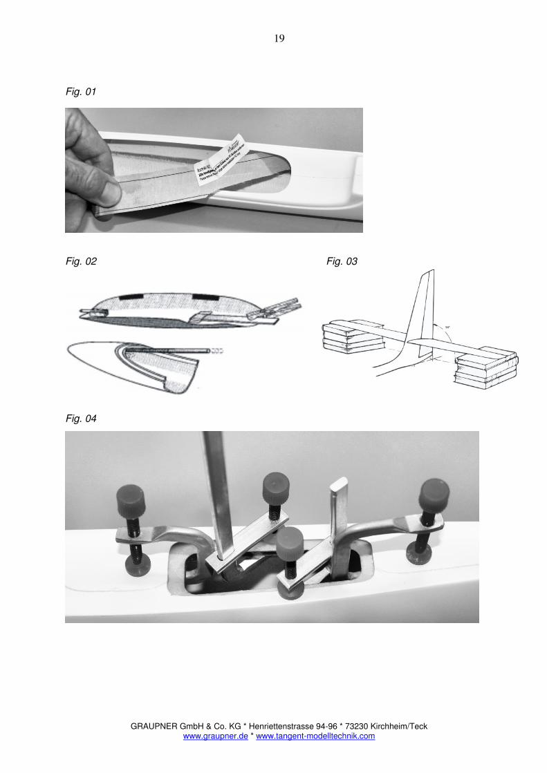
Fig 01 – Remove the temporary adhesive strips
GRAUPNER GmbH & Co. KG * Henriettenstrasse 94-96 * 73230 Kirchheim/Teck www.graupner.de * www.tangent-modelltechnik.com
6
Completing the canopy.
The Carbon canopy is supplied ready made and requires only minimal finishing. Place the canopy on the fuselage opening, carefully check the joint and adjust as necessary for a perfect fit. Minimum gap and good overall appearance will be your just reward for a little extra time and effort at this stage. Follow the steps below to install the canopy retainer, taking care to check the fit at each stage.
Installing the canopy retainer.
The canopy is held in place by a combination of a forward canopy pin and a rear GRP leaf spring. The forward canopy pin is held in place by the channelled hardwood support. The support is glued to the inside of the canopy about 50mm aft of the canopy edge such that the tip of the pin is just inside the edge of the canopy. The canopy pin is glued into the channel in the hardwood support – such that the pin protrudes sufficiently from the front of the support to engage with the rim of the fuselage opening. Re-check and adjust as necessary to achieve a good fit. Be sure to roughen the inside of the canopy with abrasive paper before gluing to ensure a good bond. The rearward canopy fixing is made using the GRP leaf-spring which is bonded to the inside of the canopy and held in place with one or two layers of fibreglass cloth suitably wetted with epoxy resin. Be sure to roughen-up the inside of the canopy with abrasive paper before bonding the leaf-spring in place. Test fit the canopy, and use a 3mm drill or suitable round file to form a recess in the forward rim of the fuselage opening to accommodate the forward canopy pin. Re-check and trim carefully until a perfect fit is achieved.
Tip. Work carefully and accurately. Your patience will be rewarded by a tight fitting canopy!
Fig 02. Canopy catch
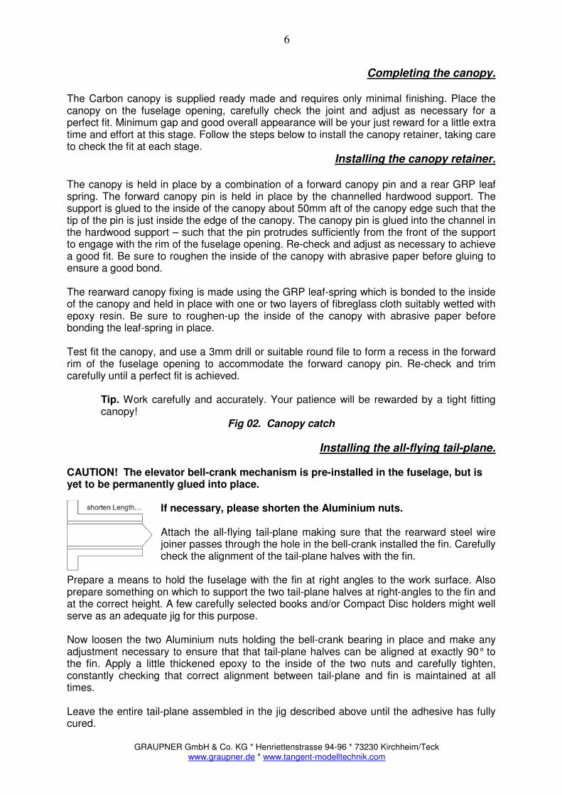
Installing the all-flying tail-plane. CAUTION! The elevator bell-crank mechanism is pre-installed in the fuselage, but is yet to be permanently glued into place.
If necessary, please shorten the Aluminium nuts. Attach the all-flying tail-plane making sure that the rearward steel wire joiner passes through the hole in the bell-crank installed the fin. Carefully check the alignment of the tail-plane halves with the fin.
Prepare a means to hold the fuselage with the fin at right angles to the work surface. Also prepare something on which to support the two tail-plane halves at right-angles to the fin and at the correct height. A few carefully selected books and/or Compact Disc holders might well serve as an adequate jig for this purpose. Now loosen the two Aluminium nuts holding the bell-crank bearing in place and make any adjustment necessary to ensure that that tail-plane halves can be aligned at exactly 90° to the fin. Apply a little thickened epoxy to the inside of the two nuts and carefully tighten, constantly checking that correct alignment between tail-plane and fin is maintained at all times. Leave the entire tail-plane assembled in the jig described above until the adhesive has fully cured.

GRAUPNER GmbH & Co. KG * Henriettenstrasse 94-96 * 73230 Kirchheim/Teck www.graupner.de * www.tangent-modelltechnik.com
7
Tip: While working with adhesives in this area apply thin parcel tape over the sides of the fin in the area of the bearing and cut through the tape to expose the holes. This will ensure that any excess adhesive does not spoil the finish on the fuselage.
Fig 03. Alignment of the all-flying tail plane.
Completing the tail-plane halves.
Work on the uncovered tail-plane panels is limited to finishing the root outline to match the profile of the fin. The tail-plane halves are factory finished, but some may wish to achieve an even more accurate match by carefully working the root area using a fine grade abrasive paper.
Note: The joiner tubes installed in the tail-plane halves incorporate the integrated all moving TA Tail-Lock mechanism.
Before fitting the joiners into the brass tubes for the first time, check that the wire joiners are perfectly straight and burr free. When pressing the tail-plane halves into place, you will feel a mild mechanical resistance which is sufficient to hold the tail-plane halves securely in-place during flight.
Vertical stabiliser and rudder
Note: Customers building the ARC version may wish to take this opportunity to adjust the profile of the leading edge of the rudder to match the trailing edge of the fin.
The rudder supplied in the kit is complete and requires only minimal finishing. The rudder hinge is formed by a Steel wire running in a factory installed pivot tube in the leading edge of the rudder. Start by cleaning up the rudder push-rod shroud using a suitable (8-10mm) round file. Similarly file a small semi-circular recess in the top of the fin to clear the leading edge of the rudder. You may also find it necessary to generally clean-up the area around the inside edge of fin post, to ensure that the rudder can move freely within the opening.
Locate and open-up the two hinge points along the leading edge of the rudder and carefully mark the corresponding hinge points along the centre of the rudder post. Now drill the holes using a Ø 3.5 mm drill to accommodate eye-bolts used to form the hinge, and screw these into the rudder post, but do not bond in place just yet. Insert the fibreglass hinge post through the guide tube located in the leading edge of the rudder such that it passes through the holes in the eye-bolts – to form an effective hinge. Now carefully check the movement and throw of the rudder with respect to the fin and adjust the depth of the hinge, by screwing in (or out) the eye-bolts until you find the optimum depth. Mark the position of the eye-bolts before finally bonding into place using a suitably thickened epoxy, re-install the rudder and adjust as necessary before finally allowing the hinge points to set.
Tip: It is possible to unscrew the hinge bolt and reset it with a little more adhesive should you find it necessary to make an adjustment after the hinge bolts have been set into the fin post.
The rudder is attached by pressing the supplied composite hinge rod down through the pivot tube from the top, and engaging in each of the hinge points.
GRAUPNER GmbH & Co. KG * Henriettenstrasse 94-96 * 73230 Kirchheim/Teck www.graupner.de * www.tangent-modelltechnik.com
8
Rudder control horn
Note: Customers building the ARF version will need to carefully remove a little of the covering in the area of the rudder control horn. Those building the ARC version may prefer to complete this step once the rudder has been covered.
Carefully mark out the position of the rudder control horn to align with the shroud in the rear of the fuselage and the rudder control linkage. Try to locate the horn as close as possible to the pivot line, and at exactly 90 degrees to the rudder hinge line. Take care to avoid any restriction caused by the rudder horn touching the shroud in the fuselage. Now drill a 4 mm hole at the point where the rudder horn is to be installed. The hole should be as deep as possible but take care not to pierce the skin on the other side of the rudder. Undermine the hole using a sharp tool so as to increase area available to the adhesive and bond the rudder horn into place using suitably thickened epoxy.
Wing Saddle
Roughen the inside of the fuselage opening in the area of the wing-saddle with 80 grit abrasive paper to achieve a good bond. Insert the ply-wood reinforcing piece and carefully centre in the opening before bonding in place with suitably thickened epoxy resin – as shown.
Fig 04. Wing Saddle Reinforcement Motor installation
Prepare the area where the motor mount is to be bonded to the inside of the fuselage nose with a course abrasive paper (80 Grit) to ensure a good bond. The motor mount should be installed about 1mm behind the edge of the fuselage nose. Note that the appropriate down-thrust and side-thrust is accounted for by the fuselage itself.
Tip: Fit a long nylon bolt through the centre hole in the motor mount and use the protruding part of the bolt as an aid to adjusting the precise position of the motor mount in the nose.
With the motor temporally installed, fit the propeller yoke and spinner and check the alignment of the fuselage nose with the spinner. Carefully finish the front of the fuselage nose to match the profile of your chosen spinner. Now carefully position the motor mount in place and secure with a few drops of instant adhesive before finally bonding in place with a generous bead of suitably thickened epoxy to both sides of the motor mount.
Note: Be sure to make provision for adequate air-intake to cool the drive system. Some customers may prefer to use a so called Turbo-Spinner which provides for intake of air through the spinner itself, but do make sure that adequate cooling is provided.
Only when the motor-mount is fully secure, re-install the motor (remember to use lock washers) and ensure that the drive shaft turns feely and there is adequate clearances for the propeller yoke and spinner assembly. A gap of about 1mm between the spinner and the fuselage nose is recommended. For the sake of safety, don’t install the propeller until the model is complete!
GRAUPNER GmbH & Co. KG * Henriettenstrasse 94-96 * 73230 Kirchheim/Teck www.graupner.de * www.tangent-modelltechnik.com
9
Note: Check that the screws used to secure the motor to the motor mount are not too long as they may otherwise foul the internal motor mechanism. You may find it necessary to countersink the mounting screws slightly, to achieve clearance with the propeller yoke/spinner assembly.
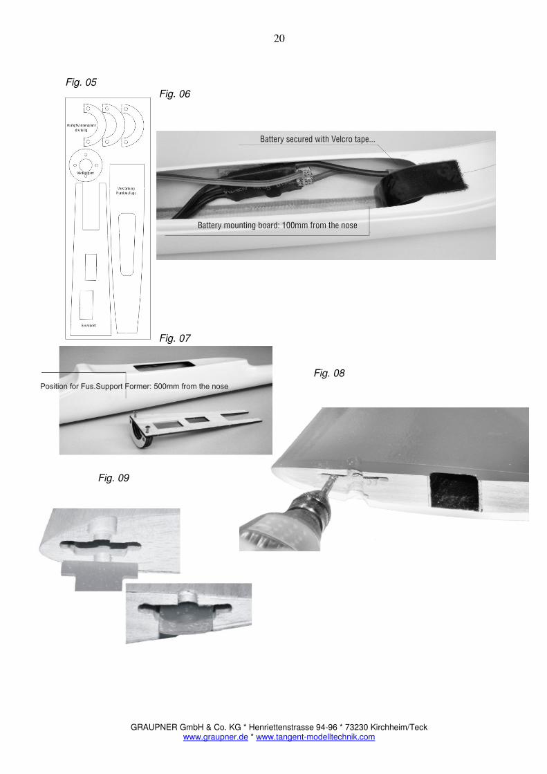
Fig.05 – Laser-cut wood kit – with motor mount
Battery Mount. The pre-cut battery mounting board is bonded into the fuselage opening about 100mm from the nose. Prepare both surfaces and bond into place with suitably thickened epoxy resin – forming a neat bead over the joint. The flight battery itself is secured to the mount using good quality Velcro tape. Use one piece of each (hook & loop) under the battery to secure it fore and aft and other in the form of a strap to secure it firmly to the battery mount.
Note: The position of the flight battery within the fuselage will significantly influence the balance point. Make sure that you can achieve the recommended centre of gravity with the flight pack installed.
Note: Ensure that the flight pack is both adequately secured and readily accessible for installation and removal at the flying site.
Fig.06 - Flight Battery Mount
Fuselage Support Former.
Assemble the fuselage support former from the three U-shaped formers, glued together with Beech pins for additional strength. The completed assembly fits into the fuselage opening just below the wing saddle - at a position 500mm from the nose. Prepare the surfaces to be bonded and dry fit the assembly and bond into place with suitably thickened epoxy only once the servo mounting tray has been installed.
Fig. 07 – Fuselage Support Former & Servo Mounting Tray
GRAUPNER GmbH & Co. KG * Henriettenstrasse 94-96 * 73230 Kirchheim/Teck www.graupner.de * www.tangent-modelltechnik.com
10
Tip: Use a disposable syringe and a short piece of scrap Bowden tube to pipe a bead of thickened epoxy resin into exactly the right spot.
Servo Mounting Tray & Speed Controller.
The laser-cut servo mounting tray fits snugly into the fuselage cockpit opening. The servo tray is positioned such that it is flush against the fuselage support former and held securely in place against the fuselage support former – using the two screws supplied in the kit. The Electronic Speed Controller (ESC) is normally held in place against the inside of the fuselage opening with good quality Velcro hook & loop tape. Be sure to locate the ESC such as to maintain minimum cable runs and allow for easy exchange of flight batteries.
Tip: To produce a good looking joint, place a strip of cling-film over the bead of epoxy resin, then smooth the bead with your fore finger. Leave the cling-film in place until the joint has cured before removing to reveal a neat joint.
Fuselage Control Linkages Temporarily install the rudder and elevator servos in the cut-outs in the servo mounting frame according to the instructions supplied with the servos. Cut the control linkages to length in the interests of saving space in the Electric Glider we suggest use of simple and effective z-bends in the push-rods – rather than clevis adaptors. Connect the push-rods and check that the control surfaces are held at neutral when the servo positions are centred. Finally secure the Bowden tubes to the inside of the fuselage side using the supplied slotted hardwood blocks and a little suitably thickened epoxy to ensure smooth running and slop free control linkages always keeping mind to minimise the length of unsupported control linkages.
Wings Wing joiner
The wing joiner is high quality square Carbon-Hybrid construction, carefully laminated by hand with a V-shaped profile and excellent structural qualities. Despite very high standards in use, small manufacturing tolerances can occur – it’s NOT a quality control problem. In the event that joiner to be a little tight, use 120 grit abrasive paper to adjust as necessary.
Wing Joint. The wing root ribs of both wing panels and factory finished and include the integral wing mount fittings. It may be necessary to prepare the openings – using a rotary tool or suitable small file.
Fig. 08. Prepare the openings in the wing roots The openings in the two wing root ribs have been specially prepared to accept the four supplied GRP connecting tongues which form the basis of the wing mount. Start by dry fitting the two sets of GRP connecting tongues in the openings in the wing root ribs (T-shaped portion first) and ensure that they are pressed firmly into the recesses provided such that the connecting tongues will overlap one another when the wings are joined. Once satisfied, bond the four connecting tongues into place using a little thickened epoxy. Note: there is no need for excessive use of epoxy as the openings are made in such a way as to prevent the tongues from being pulled out once correctly installed in the wing roots.
GRAUPNER GmbH & Co. KG * Henriettenstrasse 94-96 * 73230 Kirchheim/Teck www.graupner.de * www.tangent-modelltechnik.com
11
Once the epoxy has cured, insert the wing joiner and check that the four connecting tongues overlap. You may need to file a little material away on one or both edges to achieve a snug fit. With the wings joined together, check that there is no gap between the wing halves and carefully drill out the two holes in the overlapping connecting tongues - to accommodate the two wing bolts.
Fig. 09 & 10. – Wing Joint
The openings for the servo cables in the wing root ribs are also pre-fabricated.
Fig. 11. – Wing Servo Cable Openings The use of high current (green) plugs and sockets are recommended here as these are polarised and facilitate simplified assembly at the flying site.
Wing Mounting.
The wing mounting nuts have consciously not been pre-installed in order to accommodate inevitable tolerances in the manufacturing process. With both the wing seat and the wing joint complete, as described above, align the wing on the fuselage and carefully check the position with respect to the tail. Next temporarily secure the wing in place with adhesive tape and then, with everything still carefully aligned, drill 6mm pilot holes through the wing joint into the fuselage wing seat. Now, remove the wing assembly and open out the fixing holes to a diameter of 7.5mm – to accommodate the blind nuts which are inserted from the inside the fuselage and bonded into place with suitably thickened epoxy resin.
Tip: Use clamps to hold the blind nuts firmly in place such that the top of each nut is flush with the surface of the fuselage wing seat - until the epoxy has thoroughly cured.
Preparation of the wing servo mounts. The TA Servo LOCK system supplied with your KULT Champ kit provides a universal wing servo mounting mechanism which is both simple and very secure. Remove just sufficient Styrofoam from the inside the factory prepared servo-wells to accommodate your chosen servos up to the inside of the upper wing skin. If you do remove all the Styrofoam from within the servo well we would recommend that you apply a small piece of 100 gr./m² glass cloth, suitably wetted with epoxy resin - to protect the wing skins.
Note: In the case of the ARF version, the plywood servo frames are pre-installed at the factory.
Screw the servo covers onto the plywood frame and mark the centre of the scoops. Carefully mark and extend the centre line of the exit fairing of each servo cover to the corresponding control surface – in preparation for installation of the control horns.
GRAUPNER GmbH & Co. KG * Henriettenstrasse 94-96 * 73230 Kirchheim/Teck www.graupner.de * www.tangent-modelltechnik.com
12
Wing control horns.
Note: ARF customers will need to remove a little of the covering material while those building the ARC version may prefer to wait until after the wings have been covered before bonding the control horns in place.
Ailerons: Mark out the position of the aileron control horns on the lower surface of the aileron. The horn should be positioned directly opposite the scoop in the servo cover and about 3 mm from the aileron leading edge. Drill a series of 2mm holes and cut away the excess to form a neat slot to accommodate the supplied GRP control horns. Take care not to cut through to the upper surface of the aileron and undercut a little of the material inside the slot to allow for additional adhesive. Locate the aileron control horn such that the eye is at 90° to the hinge line and about 12mm above the lower surface of the aileron. Flaps: Similarly locate the slots to accommodate the supplied GRP flap control horns about 3mm behind the leading edge of the flap such that the eye is located about 10mm behind the flap leading edge and about 13mm above the lower surface of the flap. As before, drill a series of 2mm diameter holes and cut away the excess to form a neat slot to accommodate the supplied GRP control horns. Take care not to cut through to the upper surface of the aileron and undercut a little of the material inside the slot to allow for additional adhesive. Once satisfied with the position of the control horns, roughen the ends of each and bond the GRP control horns into place using thickened epoxy and allow to cure thoroughly.
Wing servo wiring. Prepare the cable harnesses required to connect the wing mounted aileron and flap servos to the receiver system in the fuselage. Be sure to use good quality twisted servo leads with a wire diameter of no less than 0.25 mm ² capable of delivering adequate current for the multiple wing servos under load. Pay careful attention to the solder connections ensuring good mechanical and electrical joint in each case. Be sure to insulate each joint with heat-shrink for additional security. Some may wish to apply a bead of silicone compound to the soldered ends to avoid stress points when handling the connectors.
Note: Quality cable sets, including connectors and separation filters are available via the specialist model trade; choose high quality components for optimum reliability. In the case where flying leads are used, take care always to handle the leads only by the connectors. Don’t pull on the leads!
ARF – customers should now proceed with the installation of the radio control system. ARC – customers should no proceed with the finishing/covering of the airframe.
The basic airframe is now complete!
GRAUPNER GmbH & Co. KG * Henriettenstrasse 94-96 * 73230 Kirchheim/Teck www.graupner.de * www.tangent-modelltechnik.com
13
Finishing Attention! Your new KULT Champ is built using very sophisticated LTSCP (Load Specific Covering Thickness Procedure) for superb flying characteristics, but this also has the effect of considerably enhancing the thermal conductivity and as such particular care must be taken to avoid excessive heat when using heat-shrink covering films on the wings and tail-plane. Use low temperature heat-shrink covering films and make every effort to avoid prolonged exposure to heat as the Polystyrene cores can be destroyed if exposed to excessive heat. Polystyrene starts to melt at 70°C!
Film covering – all the wooden surfaces are supplied pre-sanded, but will benefit from further fine finishing prior to covering. Follow the instructions provided with the covering materials, always taking care to make all joins in the direction of the air-flow. As an alternative to our own high stable decorative vinyl based covering material, we can also recommend Oracover (Profilm) covering materials. When covering the control surfaces with integrated Elastik Flaps (elastic hinges), take care to apply the film with the moving surfaces fully deflected so as not to restrict the movement Fibre-glass finish – for the ultimate finish, cover the wings and tail-plane with a lightweight glass-fibre cloth and treat with a suitable finishing resin. This involves a specialist process which is well documented in the popular model trade. Choose good quality materials and follow the manufacturer’s instructions. Take care not to add excessive weight! DESIGN Models. Our DESIGN range of models are supplied with pre-printed graphics which are both lightweight and durable. Please observe the following simple steps to maintain the appearance:
• TA-Film is stable up to a nominal temperature of 700C so care should be taken not to expose the surfaces to excess heat. The use of a normal hairdryer is all that is required to soften the material should it eventually become necessary.
• The graphics are waterproof but are not resistant to solvents. Clean your model with a mild solution of soapy water applied with a soft sponge and dry carefully to restore the fine finish.
• Do not under any circumstances use cleaning products which contain concentrated alcohol or acetone as a solvent.
Radio Control Equipment Installation. The precise positioning of the components installed in the nose of the fuselage will depend to some degree on your choice of receiver battery. Check the physical layout of the components, bearing in mind the recommended centre of gravity point. Fuselage servo installation Install the fuselage mounted servos in the cut-outs in the servo mounting frame according to the instructions supplied with the servos. Attach the linkages so as to use the maximum available throw, i.e. use the inner-most holes at the servo arm and the out-most holes at the control horn! Always ensure that all the linkages are secure, there is no binding and are slop-free.
GRAUPNER GmbH & Co. KG * Henriettenstrasse 94-96 * 73230 Kirchheim/Teck www.graupner.de * www.tangent-modelltechnik.com
14
Wing servo installation The servos themselves are simply bonded to the inside of the servo cover scoop using suitably thickened epoxy and screwed onto the plywood frames (see also the installation note supplied with the TA servo LOCK set). Be sure to roughen the surface of the servo cover to ensure a good bond.
Tip: Protect the servos with heat shrink sleeve. This makes for easy removal and replacement of the servo, but care should be taken so as not to overheat the servos while applying the sleeve.
Ensure that the servo output arms are set at 90° with the servo electrically centred. Prepare the linkages, using threaded rod, clevises and lock-nuts remembering to apply a drop of thread-lock to the lock nuts or apply a short length of heat-shrink over the joint. Secure the servo covers in place using the four small screws provided. Use a countersink tool to recess the screw heads into the servo covers to improve both the appearance and the aerodynamic performance. Receiver battery The receiver battery is positioned in the nose, forward of the servo mounting tray and must be adequately secured for flight. Receiver installation The receiver itself is best installed on the servo mounting tray, to the rear of the fuselage cockpit opening; a good quality Velcro hook & loop material is quite adequate for this purpose. Receiver Antenna The receiver antenna is ideally inserted into a suitable antenna tube (or plastic Bowden tube) and inserted down the length of the fuselage Although there is a certain amount of Carbon used in the construction of the fuselage, we would suggest that there is no problem running the antenna down the inside of the fuselage boom (we fly all our models this way). However, ALWAYS carry out a thorough range test before flying the model and if any doubt whatsoever then allow the antenna to hang freely.
Tip: Never install the antenna taut, but allow some slack in the wire to allow for small movements within the fuselage.
The model is now largely complete, but some very important work remains to be done while still in the workshop.
Balancing & Adjusting. The correct centre of gravity and longitudinal dihedral are first determined theoretically, and then confirmed in practice by test flying the model. A successful first test flight is invariably a matter of good preparation!
GRAUPNER GmbH & Co. KG * Henriettenstrasse 94-96 * 73230 Kirchheim/Teck www.graupner.de * www.tangent-modelltechnik.com
15
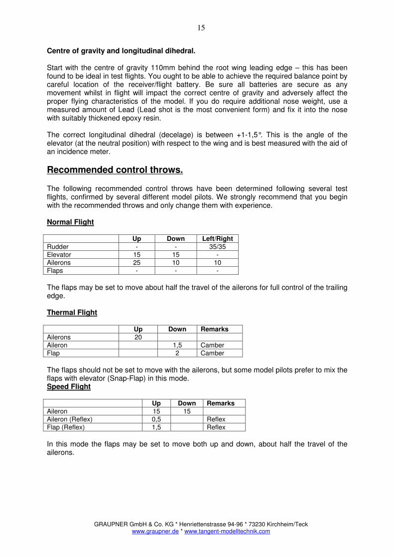
Centre of gravity and longitudinal dihedral. Start with the centre of gravity 110mm behind the root wing leading edge – this has been found to be ideal in test flights. You ought to be able to achieve the required balance point by careful location of the receiver/flight battery. Be sure all batteries are secure as any movement whilst in flight will impact the correct centre of gravity and adversely affect the proper flying characteristics of the model. If you do require additional nose weight, use a measured amount of Lead (Lead shot is the most convenient form) and fix it into the nose with suitably thickened epoxy resin. The correct longitudinal dihedral (decelage) is between +1-1,5°. This is the angle of the elevator (at the neutral position) with respect to the wing and is best measured with the aid of an incidence meter.
Recommended control throws.
The following recommended control throws have been determined following several test flights, confirmed by several different model pilots. We strongly recommend that you begin with the recommended throws and only change them with experience. Normal Flight Up Down Left/Right
Rudder - - 35/35 Elevator 15 15 - Ailerons 25 10 10 Flaps - - -
The flaps may be set to move about half the travel of the ailerons for full control of the trailing edge. Thermal Flight Up Down Remarks
Ailerons 20 Aileron 1,5 Camber Flap 2 Camber
The flaps should not be set to move with the ailerons, but some model pilots prefer to mix the flaps with elevator (Snap-Flap) in this mode. Speed Flight Up Down Remarks
Aileron 15 15 Aileron (Reflex) 0,5 Reflex Flap (Reflex) 1,5 Reflex
In this mode the flaps may be set to move both up and down, about half the travel of the ailerons.
GRAUPNER GmbH & Co. KG * Henriettenstrasse 94-96 * 73230 Kirchheim/Teck www.graupner.de * www.tangent-modelltechnik.com
16
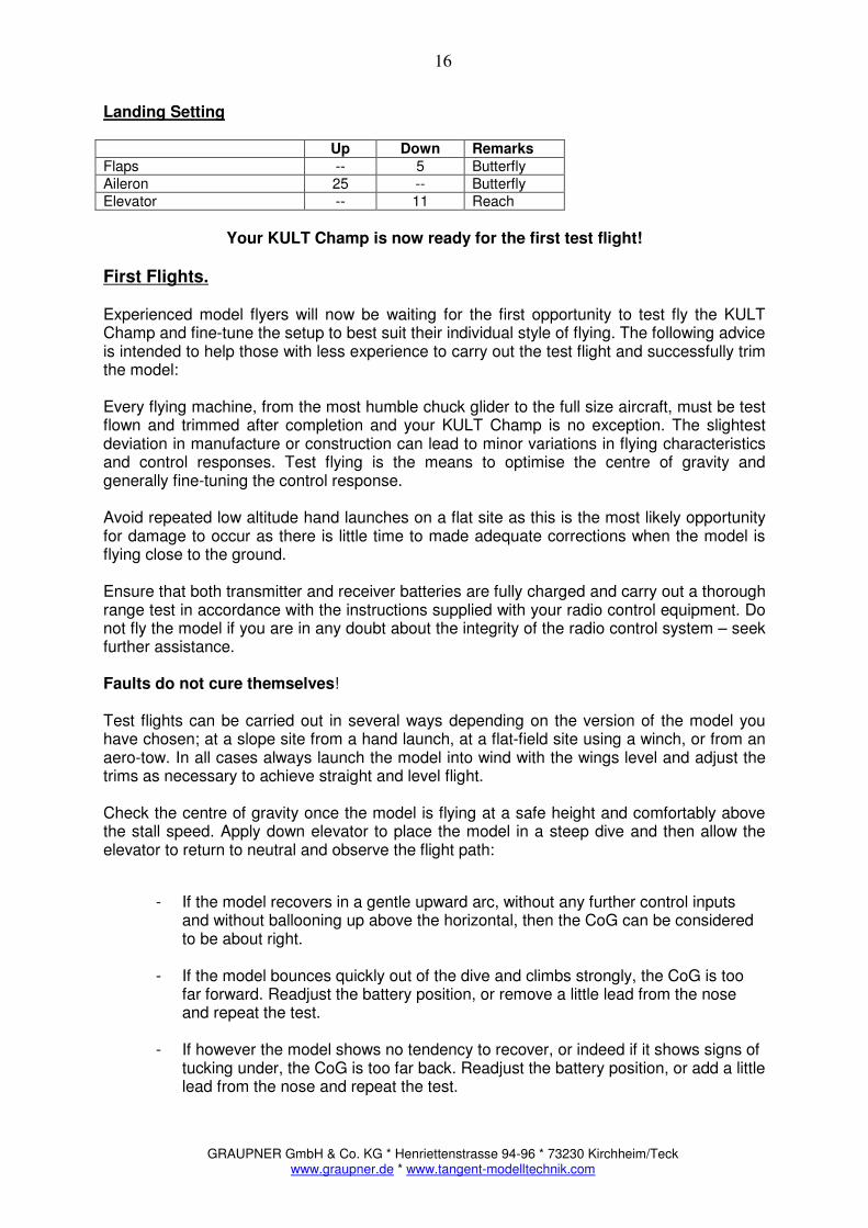
Landing Setting Up Down Remarks
Flaps -- 5 Butterfly Aileron 25 -- Butterfly Elevator -- 11 Reach
Your KULT Champ is now ready for the first test flight!
First Flights. Experienced model flyers will now be waiting for the first opportunity to test fly the KULT Champ and fine-tune the setup to best suit their individual style of flying. The following advice is intended to help those with less experience to carry out the test flight and successfully trim the model: Every flying machine, from the most humble chuck glider to the full size aircraft, must be test flown and trimmed after completion and your KULT Champ is no exception. The slightest deviation in manufacture or construction can lead to minor variations in flying characteristics and control responses. Test flying is the means to optimise the centre of gravity and generally fine-tuning the control response. Avoid repeated low altitude hand launches on a flat site as this is the most likely opportunity for damage to occur as there is little time to made adequate corrections when the model is flying close to the ground. Ensure that both transmitter and receiver batteries are fully charged and carry out a thorough range test in accordance with the instructions supplied with your radio control equipment. Do not fly the model if you are in any doubt about the integrity of the radio control system – seek further assistance. Faults do not cure themselves! Test flights can be carried out in several ways depending on the version of the model you have chosen; at a slope site from a hand launch, at a flat-field site using a winch, or from an aero-tow. In all cases always launch the model into wind with the wings level and adjust the trims as necessary to achieve straight and level flight. Check the centre of gravity once the model is flying at a safe height and comfortably above the stall speed. Apply down elevator to place the model in a steep dive and then allow the elevator to return to neutral and observe the flight path:
- If the model recovers in a gentle upward arc, without any further control inputs and without ballooning up above the horizontal, then the CoG can be considered to be about right.
- If the model bounces quickly out of the dive and climbs strongly, the CoG is too far forward. Readjust the battery position, or remove a little lead from the nose and repeat the test.
- If however the model shows no tendency to recover, or indeed if it shows signs of tucking under, the CoG is too far back. Readjust the battery position, or add a little lead from the nose and repeat the test.
GRAUPNER GmbH & Co. KG * Henriettenstrasse 94-96 * 73230 Kirchheim/Teck www.graupner.de * www.tangent-modelltechnik.com
17
Safety.
Our hobby is very important to us and as such it is essential that we recognise the responsibilities associated with the building and flying of model aircraft:
• Carefully built models exhibit outstanding flying characteristics and the highest levels
of reliability and safety. • Always carry out thorough pre-flight checks – observing structural integrity of the
model as well as correct movement and sense of all the flying surfaces. • Always carry out a through range check on all new models or following any change of
RC components. • Always check that your channel is free before switching on your transmitter.
• Adequate third-party insurance is essential. Check the local laws governing model flying in your region before flying your model.
• Give due consideration to others when flying aerobatic manoeuvres and never fly low and/or fast over other people.
• Always be aware of the vulnerability of each individual component of your RC system and maintain it responsibly.
• Always give due consideration to other model flyers, provide ample air-space and observe the local system of channel allocation.
If in doubt – please ask. If you are unsure about any aspect of flying your model safely, please seek the advice of an experienced aero-modeller or contact your dealer.
A final word Get to know your KULT Champ. The models excellent performance and exceptional flight envelope is renowned. Enjoy one of the few sports in which the combination of technology coupled with your own skill and the conditions that Mother Nature provides are combined to provide the sheer enjoyment of flying. We at GRAUPNER / TANGENT-Model sport, wish you much pleasure building and flying your new model! GRAUPNER / TANGENT Model Sport

GRAUPNER GmbH & Co. KG * Henriettenstrasse 94-96 * 73230 Kirchheim/Teck www.graupner.de * www.tangent-modelltechnik.com
18
Parts List.
Qty Description Used Material Dimension
1 Set assembly instruction Paper DIN A4
1 Set decal Vinyl Plot
1 Fuselage GRP Ready made
1 Canopy Carbon Ready made
1 Set wing panels Foam/Obechi Ready made
1 Set tail-plane halves Foam/Obechi Ready made
1 Rudder Balsa Ready made
1 Wire parts set Wire BOM
1 Wooden parts Wood BOM
1 Servo lock set Plastic BOM
1 Wing joiner Composite Square
Wire Set
2 Piano wire Rudder/Elevator Spring steel D1.4 * 1400
1 Rudder hinge pin Rudder hinge Composite D2*400
Wooden Parts
1 Pin carrier Canopy pin Abachi 12 * 12 70
1 Servo mounting tray Fuselage Plywood Pre-cut
1 Fuselage reinforcing Fuselage Plywood Pre-cut
1 Fuselage former Fuselage Plywood Pre-cut
1 Motor mount Fuselage Plywood Pre-cut
1 Battery mount Fuselage Plywood 3*30*70
Accessories
10 Clevis Control linkages Steel M 2.5
2 Clevis adaptor Control linkage Brass M 2.5
4 Threaded rods Control linkages Steel M 2.5
2 Control horns Aileron linkage GRP Ready made
2 Control horns Flap linkage GRP Ready made
10 Lock nuts Control linkages Brass M 2.5
1 Tailplane Joiner Tail plane Steel D3*140
1 Tailplane Joiner Tail plane Steel D3*100
1 * Bell-crank assembly Elevator *installed
1 GRP leaf spring Canopy GRP Ready made
1 Eye Bolts Rudder hinge Alu M4/2mm
1 Eye Bolts Rudder horn Alu M4/1.6mm
1 Winch hook Fuselage hook Steel Ready made
1 Bungee Hook Fuselage hook Steel Ready made
2 Screws Servo Mount Steel 3*20
4 GRP-Wingfixer Wingfixing GRP Ready made
2 Drive-in nut Wingfixing Steel M6
2 Bolts Winfixing Nylon M6
Servolock Set
4 Servo frame Wings Milled plywood
2 Servo covers/Left open Wings Plastic Ready made
2 Servo covers/Right open Wings Plastic Ready made
16 Self tapping screw Wings Steel M 2 * 10
1 Instruction sheet Wings Paper
Note: Contents and technical details subject to change without notice.
GRAUPNER GmbH & Co. KG * Henriettenstrasse 94-96 * 73230 Kirchheim/Teck www.graupner.de * www.tangent-modelltechnik.com
19
Fig. 01
Fig. 02 Fig. 03
Fig. 04
GRAUPNER GmbH & Co. KG * Henriettenstrasse 94-96 * 73230 Kirchheim/Teck www.graupner.de * www.tangent-modelltechnik.com
20
Fig. 05
Fig. 06
Fig. 07
Fig. 08
Fig. 09

GRAUPNER GmbH & Co. KG * Henriettenstrasse 94-96 * 73230 Kirchheim/Teck www.graupner.de * www.tangent-modelltechnik.com
21
Fig. 10
Fig. 11
Fig. 12