Embed Size (px)
Citation preview

»414@#
OWNER'S MANUAL
3D0028100A

2
Table Of Contents
Safety Instructions 3The PORTASTUDIO 414 MKII is... 4The Recording System 5
The Three Steps to Multitrack 5Understanding the Mixer 6-7
Signal Flow in the 414 MKII Mixer 6Tape Cue Monitor System 7
Multitrack Cassette Recorder 8Track Format and Tape
Recommendations 8-9Optional Accessories 10PORTASTUDIO 414 MKII Brief Guide 11-14Step-By-Step Operation Guide 15-23
Let's Try the 414 MKII Mixer 15How to Record on Track 1 16Track 1 Playback through TAPE CUE 17How to Make an Overdub on Track 2 18How to Record Tracks 3 and 4 20How to Record Many Sources onto a
Single Track 20How to Record a Mix onto Two Tracks
Simultaneously 21Recording on More than Two Tracks
Simultaneously : Direct Recording 22How to Mix Down 22
PUNCH-IN or INSERT Recording 24-25Preliminary 24Punch-in Procedure 25
Bouncing Tracks (Ping-Pong) 26Ping-pong Procedure 26
Using Effects with the PORTASTUDIO 414 MKII 27-28
Setting Effect Send Levels 27Setting the Output Level of Effect
Devices 27Setting the Mix/Balance Control
on Effect Devices 28How to Connect Your Effects Devices 28
Syncing MIDI-Tape —Using the TASCAM MTS-30 29
Troubleshooting 30Features and Controls 31-35
414 MKII MIXERInput Section 32Stereo Input Section 33Monitor Section 33Master Section 33Output Section 33
414 MKII RECORDERCassette Loading and dbx System 34Transport Controls 34Track Controls 35Displays 35
Care and Maintenance 35-36How the dbx Works 36Specifications 37-38Block Diagram 39-40Level Diagram 41
"© Copyright 1999, TEAC Corporation"All rights reserved under international and Pan American copyright conventions.This book may not be reproduced in whole or in part, by mimeograph or any other means, withoutpermission.
"The following marking is located on the bottom of the unit."
This appliance has a serial number locatedon the rear panel. Please record the modelnumber and serial number and retain themfor your records.Model numberSerial number
WARNING: TO PREVENT FIRE OR SHOCKHAZARD, DO NOT EXPOSE THIS APPLIANCE TO RAIN OR MOISTURE.
CAUTION: TO REDUCE THE RISK OF ELECTRIC SHOCK, DO NOT REMOVE COVER (OR BACK). NO USER-SERVICEABLE PARTSINSIDE. REFER SERVICING TO QUALIFIED SERVICE PERSONNEL.
The lightning flash with arrowhead symbol, within equilateral triangle, is intended to alertthe user to the presence of uninsulated "dangerous voltage" within the product's enclosurethat may be of sufficient magnitude to constitute a risk of electric shock to person.
The exclamation point within an equilateral triangle is intended to alert the user to thepresence of important operating and maintenance (servicing) instructions in theliterature accompanying the appliance.
CAUTIONRISK OF ELECTRIC SHOCK
DO NOT OPEN

3
Safety Instructions
CAUTION:• Read all of these Instructions.• Save these Instructions for later use.• Follow all Warnings and Instructions marked on the
audio equipment.
1) Read Instructions — All the safety and operating instructions shouldbe read before the product is operated.2) Retain Instructions — The safety and operating instructions shouldbe retained for future reference.3) Heed Warnings — All warnings on the product and in the operatinginstructions should be adhered to.4) Follow Instructions — All operating and use instructions should befollowed.5) Cleaning — Unplug this product from the wall outlet before cleaning.Do not use liquid cleaners or aerosol cleaners. Use a damp cloth forcleaning.6) Attachments — Do not use attachments not recommended by theproduct manufacturer as they may cause hazards.7) Water and Moisture — Do not use this product near water _ forexample, near a bath tub, wash bowl, kitchen sink, or laundry tub; in a wetbasement; or near a swimming pool; and the like.8) Accessories — Do not place this product on an unstable cart, stand,tripod, bracket, or table. The product may fall, causing serious injury to achild or adult, and serious damage to the product. Use only with a cart,stand, tripod, bracket, or table recommended by the manufacturer, or soldwith the product. Any mounting of the product should follow themanufacturer’s instructions, and should use a mounting accessoryrecommended by the manufacturer.9) A product and cart combination should be moved with care. Quickstops, excessive force, and uneven surfaces may cause the product and cartcombination to overturn.
10) Ventilation — Slots and openings in the cabinet are provided forventilation and to ensure reliable operation of the product and to protect itfrom overheating, and these openings must not be blocked or covered. Theopenings should never be blocked by placing the product on a bed, sofa, rug,or other similar surface. This product should not be placed in a built-ininstallation such as a bookcase or rack unless proper ventilation is providedor the manufacturer’s instructions have been adhered to.11) Power Sources — This product should be operated only from thetype of power source indicated on the marking label. If you are not sure ofthe type of power supply to your home, consult your product dealer or localpower company. For products intended to operate from battery power, orother sources, refer to the operating instructions.12) Grounding or Polarization — This product may be equipped with apolarized alternating-current line plug (a plug having one blade wider thanthe other). This plug will fit into the power outlet only one way. This is asafety feature. If you are unable to insert the plug fully into the outlet, tryreversing the plug. If the plug should still fail to fit, contact your electricianto replace your obsolete outlet. Do not defeat the safety purpose of thepolarized plug.13) Power-Cord Protection — Power-supply cords should be routed sothat they are not likely to be walked on or pinched by items placed upon oragainst them, paying particular attention to cords at plugs, conveniencereceptacles, and the point where they exit from the product.14) Outdoor Antenna Grounding — If an outside antenna or cablesystem is connected to the product, be sure the antenna or cable system isgrounded so as to provide some protection against voltage surges and built-up static charges. Article 810 of the National Electrical Code, ANSI/NFPA70, provides information with regard to proper grounding of the mast andsupporting structure, grounding of the lead-in wire to an antenna dischargeunit, size of grounding conductors, location of antenna-discharge unit,connection to grounding electrodes, and requirements for the groundingelectrode.
"Note to CATV system installer:This reminder is provided to call the CATV system installer’s attention toSection 820-40 of the NEC which provides guidelines for proper groundingand, in particular, specifies that the cable ground shall be connected to thegrounding system of the building, as close to the point of cable entry aspractical.
15) Lightning — For added protection for this product during a lightningstorm, or when it is left unattended and unused for long periods of time,unplug it from the wall outlet and disconnect the antenna or cable system.This will prevent damage to the product due to lightning and power-linesurges.16) Power Lines — An outside antenna system should not be located inthe vicinity of overhead power lines or other electric light or power circuits,or where it can fall into such power lines or circuits. When installing anoutside antenna system, extreme care should be taken to keep from touchingsuch power lines or circuits as contact with them might be fatal.17) Overloading — Do not overload wall outlets, extension cords, orintegral convenience receptacles as this can result in risk of fire or electricshock.18) Object and Liquid Entry — Never push objects of any kind intothis product through openings as they may touch dangerous voltage pointsor short-out parts that could result in a fire or electric shock. Never spillliquid of any kind on the product.19) Servicing — Do not attempt to service this product yourself asopening or removing covers may expose you to dangerous voltage or otherhazards. Refer all servicing to qualified service personnel.20) Damage Requiring Service — Unplug this product from the walloutlet and refer servicing to qualified service personnel under the followingconditions:a) when the power-supply cord or plug is damaged.b) if liquid has been spilled, or objects have fallen into the product.c) if the product has been exposed to rain or water.d) if the product does not operate normally by following the operatinginstructions. Adjust only those controls that are covered by the operatinginstructions as an improper adjustment of other controls may result indamage and will often require extensive work by a qualified technician torestore the product to its normal operation.e) if the product has been dropped or damaged in any way.f ) when the product exhibits a distinct change in performance _ thisindicates a need for service.21) Replacement Parts — When replacement parts are required, besure the service technician has used replacement parts specified by themanufacturer or have the same characteristics as the original part.Unauthorized substitutions may result in fire, electric shock, or otherhazards.22) Safety Check — Upon completion of any service or repairs to thisproduct, ask the service technician to perform safety checks to determinethat the product is in proper operating condition.23) Wall or Ceiling Mounting — The product should be mounted to awall or ceiling only as recommended by the manufacturer.24) Heat — The product should be situated away from heat sources suchas radiators, heat registers, stoves, or other products (including amplifiers)that produce heat.
ANTENNALEAD INWIRE
ANTENNADISCHARGE UNIT(NEC SECTION 810-20)
GROUNDING CONDUCTOR(NEC SECTION 810-21)
GROUND CLAMPS
POWER SERVICE GROUNDINGELECTRODE SYSTEM(NEC ART 250. PART H)
NEC - NATIONAL ELECTRICAL CODE
ELECTRICSERVICEEQUIPMENT
Example of Antenna Grounding as perNational Electrical Code, ANSI/NFPA 70
GROUNDCLAMP

4
The PORTASTUDIO 414 MKII is...
The PORTASTUDIO 414 MKII is a 4-track "Multi-track Master" cassette tape recorder and a full-function mixer with 8 inputs/stereo outputs includinga balanced microphone input and a dedicated guitarinput combined into a single workstation.
Its high audio quality and creative flexibility reflectthe experience and innovation that have allowedTASCAM to earn its reputation in professional audioproduction fields, and its user-friendly design makesthe 414 MKII suitable for anyone, from expert tonovice.
Using this manual : To get the most out of your414 MKII, please take the time to read through thismanual. Some time spent now will keep you fromoverlooking some of the features that make the 414MKII a more creative tool. You may discover somenew tricks you haven't tried before.
Use of capital letters : In general, we use all uppercase type to designate a particular switch, control,jack name or label (like PAN). Transport modes andsome features are described with an upper case firstletter (like Record mode).
CAUTIONTo power the PORTASTUDIO 414 MKII, useonly the provided PS-P414 AC adaptor.Using any other adaptor will cause damageto the 414 MKII, and such damage would notbe covered by the limited warranty on theproduct.
About the weld lineThere is a patterned stripe-like effect on thebottom surface of the 414 MKII unit. Thiseffect is called a "weld line" and is a naturalresult of the resin molding processemployed in the manufacture of the414 MKII unit. It is not a crack or scratch,and will cause no problems with theoperation of the 414 MKII unit.
NOTE FOR U.K. CUSTOMERS
DO NOT cut off the mains plug from thisequipment. If the plug fitted is not suitable for thepower points in your home or the cable is too shortto reach a power point, then obtain an appropriatesafety approved extension lead or consult yourdealer.
If nonetheless the mains plug is cut off, remove thefuse and dispose of the plug immediately, to avoid apossible shock hazard by inadvertent connection tothe mains supply.
If this product is not provided with a mains plug, orone has to be fitted, then follow the instructionsgiven below:
IMPORTANT. DO NOT make any connection to thelarger terminal which is marked with the letter E orby the safety earth symbol ç or coloured GREENor GREEN-and-YELLOW.
The wires in the mains lead on this product arecoloured in accordance with the following code:
BLUE: NEUTRAL
BROWN: LIVE
As these colours may not correspond with thecoloured markings identifying the terminals in yourplug proceed as follows:
The wire which is coloured BLUE must beconnected to the terminal which is marked with theletter N or coloured BLACK.
The wire which is coloured BROWN must beconnected to the terminal which is marked with theletter L or coloured RED.
When replacing the fuse only a correctly ratedapproved type should be used and be sure to re-fitthe fuse cover.
IF IN DOUBT — CONSULT A COMPETENTELECTRICIAN.

5
The Recording System
The PORTASTUDIO 414 MKII is a complete audioproduction facility in a single box. It is divided intotwo major sections: a full-function mixer and a 4-channel, multitrack cassette recorder.
To complete the recording system, you'll additionallyneed these: input devices (microphones,instruments), output devices (headphones), 2 trackrecorder, effects processors, etc.
The Three Steps to Multitrack
In TRACKING and OVERDUBBING, the mixerinputs are usually microphones or instruments, goingto different tracks of the recorder.
In OVERDUBBING, the MONITOR section andTAPE CUE of the mixer must be used to listen to
previous tracks while you record new ones, so thereis a two-way flow through the console.
In MIXDOWN, signal comes from the multitrackand is sent to an external 2-track recorder.

6
Understanding the Mixer
Signal Flow in the 414 MKII Mixer
The illustration below shows how input signals passthrough the 414 MKII Mixer section. After theMASTER fader they go to the L/R LINE OUT jacks.
This is the most important signal route in the mixerand is called "Main Mix".

7
Understanding the Mixer
Tape Cue Monitor System
The TAPE CUE mix and MONITOR switches arealso crucial for successful multitrack recording,because they control what you hear in theheadphones. This CUE mix is totally independentfrom the Main Mix going to tape. If you don't usethe CUE mix, you run the risk of accidentally"bouncing tracks" every time you record newmaterial.
The 4 TAPE CUE controls act like a separate 4x1mixer, dedicated solely so you can hear playbackfrom the multitrack recorder in your headphones.Settings of these controls don't affect the mix goingto tape. When the "master" EFFECT 2/TAPE CUEselect switch located to the right of the track 4 meteris set to the right/TAPE CUE position, the channels'TAPE CUE controls are turned to the right, the"MONITOR" EFFECT 2/TAPE CUE switch ispressed on, and the MONITOR level control isturned up, you can hear tape playback in theheadphones. You can adjust the monitor level of eachtrack by adjusting its TAPE CUE control. Thechannels of the Main Mix remain free to handleexternal inputs for recording.
If you can hear tape playback in your headphoneswhen TAPE CUE is off, it means you're hearing tapethrough the Main Mix. This is correct for mixdownand bouncing tracks, but during overdubbing it cancause previous tracks to be mixed together with newtracks, instead of each part remaining separate. Usethe TAPE CUE to avoid this.
The three MONITOR switches choose whichmix(es) you can hear in the headphones/monitorspeakers — the L-R mix, the TAPE CUE mix, andthe EFFECT 1 and 2 send mixes. Press the L-Rswitch on to hear what you are recording.

8
Multitrack Cassette Recorder
The 414 MKII records on readily available standard(Philips) Compact Cassette tape, high bias Type II.The recorder has 4 tracks while the mixer has astereo output; however, using the Direct Recordingfeature you can record on any or all of the 4 tracks atone time. For more details, see "Recording on MoreThan Two Tracks Simultaneously", page 22.
The 414 MKII's dbx Noise Reduction virtuallyeliminates unwanted tape noise. A special SYNCfeature turns off the dbx on track 4 separately,making it possible to record and play back the MIDIsync tones or SMPTE/EBU time code without beingaffected by the dbx encode/decode. This ensures thatthe sync tones/code are recorded and played backwithout unnecessary processing. With properoperating techniques, it is not necessary to leave aguard band between music and sync tone tracksbecause of the low crosstalk of the TASCAM heads.
ZERO RETURN promptly brings you back to thebeginning of a section of tape, selected byresetting the tape counter.
The tape speed can be increased or decreasedwith the PITCH CONTROL dial in bothplayback and record, to match pitch or for specialeffects.
Track Format and Tape Recommendations
Tape Speed and Track Format
The Portastudio 414 MKII records/plays at 9.5cm/sec (3-3/4 ips) which is twice (2 X) the normalspeed of a standard audio cassette.
It also employs a discrete 4-channel format headdeveloped especially by TEAC for TASCAMmultitrack cassette recorders. Here is a comparisonof various cassette formats:

9
Track Format and Tape Recommendations
Tape TypeThe Portastudio 414 MKII is internally adjusted forHIGH BIAS Type II tape. This means that for bestresults, you should only use tapes of this type. TDKSA, Maxell XL-II or equivalent formulations arerecommended. We strongly suggest that you selectone good quality brand and use it exclusively. Thetime you spend creating your multitrack master ismuch more valuable than the money you save bybuying inferior tape. The cassette shell essentiallybecomes a part of the 414 MKII's transport. Poorquality shells can cause wrinkles, snarls andshredding of the edges of the tape with use. Evensmall scratches on the tape oxide can cause"dropouts" (temporary loss of signal) on one or moretracks. High quality tapes are less likely to causeproblems in the long run.
Accidental Erase/Record ProtectionTo protect a finished master tape, it is necessary topunch out both record protect tabs. Even though youare recording in only one direction, the 414 MKIIuses the entire width of the tape. If, for example, youremove only one of the tabs, you could accidentallyinsert the cassette into the 414 MKII backwards anderase all four tracks of the master.
Tape LengthUse the shortest possible tape for a given work. It isnot unusual to play a tape 100 times before you arefinished, so select a cassette length that is as close aspossible to the length of the program you plan torecord. Cassettes C-60 length and shorter are oftenmade from thicker stock than longer cassettes.
The tape used in C-120 cassettes is extremely thinand can cause winding problems, crimping,wrinkling, and other damage to the oxide coating ofthe tape which will destroy your work. Don't useC-120s in the 414 MKII.
Remember that with twice the normal speed and the"one-side-only" 4-track single direction format, youhave only one quarter of the normal play time:
Cassette Play Time
C-46 11.5 min.
C-60 15 min.
C-90 22.5 min.
(approx.)

10
Optional Accessories
RC-30P Remote Footswitch
Head Demagnetizer
TZ-261 Cleaning Kit (Except U.S.)
MIDI-Tape Synchronizer
PW-2Y/PW-4Y Insertion Cable
HC-1 Head Cleaner & RC-1 Rubber Cleaner(U.S.only)

1211
PORTASTUDIO 414 MKII Brief Guide For detailed information on each feature, see"Features and Controls", pp. 31-35.
Channels 1 through 4
EQ HIGH : Cuts or boosts treble frequencies. Shelving point is at 10 kHz.
EQ LOW : Cuts or boosts bass frequencies. Shelving point is at 100 Hz.
EFFECT 1 and 2 : These control how much signal will go to the correspond-ing EFFECT send jacks. They get their signal from a point just after thechannel fader.
TAPE CUE : The EFFECT 2 controls can be switched to act as the TAPECUE level controls (by means of the correspondingly labeled switch) andadjust the playback level for the musicians in the studio.
PAN : Sets the pan position (left-right balance) of the channel. Note that theLeft Mix can be recorded on tracks 1 and 3, and the Right Mix onto tracks2 and 4.
INPUT : Determines where the channel signal comes from.
TAPE; Makes tape playback the channel source.GUITAR; When this is selected, makes the GUITAR input the channelsource. If no instrument is plugged into the GUITAR input, this is equiva-lent to OFF.MIC/LINE; Brings the MIC/LINE input into the channel.
Channel fader : Sets the volume of the channel feeding the MASTER fader.
TRIM : Sets how much preamplification will be added to the MIC/LINE IN jack.Push up if the signal needs amplification, pull down if the signal is so loudit is distorting the mixer electronics.
MIC/LINE IN (on the front) : These are the input jacks for the mixer channels.Line-level, unbalanced signal sources (such as electronic instruments)may be connected here. You can also connect lower-level signals (down to–50 dBV) and use the TRIM control to amplify them.
INPUT L & R : These balanced XLR-type connectors are for balanced micro-phones. If a signal source is connected to the front MIC/LINE IN jack cor-responding to the XLR-type connector where a microphone is connected(L=1 or 3, R=2 or 4), the microphone signal input here is ignored. In otherwords, if you want to use microphones with these connectors, make surethat nothing is plugged into the corresponding MIC/LINE IN jack at thattime.
GUITAR IN jack and TRIM control : This 1/4" jack is specially designed forconnection of an electric guitar (or bass guitar). This dedicated input isprovided because these instruments have an impedance that is differentto that of microphones or line level sources. A guitar played through thisjack will be used as the signal to a channel, if the INPUT switch of thechannel is set to the center GUITAR position. Use the TRIM control bythis jack to match the level of your guitar.
Input Selection and Adjustment
Channels 5 through 8
STEREO INPUTS : Connect any line-level signal (such asan effect return, or electronic instrument) here.
Mono Feature : Plug a mono signal into the channel5-6 (L/MONO) jack and leave the 7-8 (R) jack empty.The signal is then automatically taken into the two pairsof channels (5-6 and 7-8).
LEVEL : Controls the volume of both the left and rightinputs simultaneously on their way to the respectivestereo mix sides.
LEVEL : This sets the output level of the monitor mix feed-ing the MON OUT and PHONES jacks.
MONITOR switches : These select the source of the MONOUT and PHONES jacks.
– What you hear when the EFFECT 2/TAPE CUEswitch is pressed on, depends on the setting of themaster select switch below.
EFFECT 2/TAPE CUE : When set to EFFECT 2, sends sig-nals after the channel fader to effect devices, and whenset to TAPE CUE, sends playback signals to the moni-tor.
MASTER fader : This sets the total output level of thestereo mix.
Master Section
Monitor Section

13 14
PORTASTUDIO 414 MKII Brief Guide
DBX switch : Normally, leave this switch atON. When you use track 4 to record andplay back MIDI sync tones or time code,set to SYNC then the dbx is on for tracks1-3, and off on track 4.
Tape counter : Shows the distance the tapehas moved from a zero reference point.
Counter reset button : Press to change thecounter to "000".
PITCH CONTROL : Increases or decreasesthe speed of the transport in Play andalso in Record, over a 10% range(approx.).
Meters : The meters numbered 1-4 show theplayback or the record level of therespective tape tracks. The averagerecord level should be in the center (0),but occasional peaks up to +6 areacceptable.
ZERO RETURN : When this switch is on andyou press REW, the tape fast winds tothe counter zero point. The associatedLED blinks when the tape is rewinding,and glows solid when the 000 point isreached.
Recorder Controls
Transport keys :Principally these work the same as on anycassette recorder.
RECORD FUNCTION 1-4 : Used to select tracksto record on, and also recording sources(channels or stereo busses).
SUB IN L and R : Provide a direct route tothe MASTER fader. An outboard mixermay be connected here. The SUB IN Rjack is also used to record sync toneson track 4.
SYNC OUT : Sync tones you'll record ontrack 4 are sent out of this jack to theTASCAM MTS-30 MIDI/Tape synchro-nizer or other similar units.
LINE OUT L and R : Normally, connectthese jacks to the Left and Right inputsof your mixdown deck.
MON OUT L and R : These are connectedto an amplifier powering the controlroom speakers.
EFFECT 1 SEND : For sending post chan-nel fader signals to effects devices. Thereturns are plugged into the STEREOINPUTS.
EFFECT 2 SEND/TAPE CUE OUT : Thesignal available at this jack comes eitherfrom post channel fader for connectionto an additional effects device or fromthe tape for connection to a studiospeaker system, as selected by meansof the EFFECT 2/TAPE CUE switch.
PHONES : This carries the same mix as the MON OUT jacks,as selected by the MONITOR switches.
REMOTE PUNCH IN/OUT : Connect to this jack the optionalRC- 30P footswitch.
Connections on the Rear Panel
On the front

15
Let's Try the 414 MKII Mixer
To learn how the mixer works, we’ll use amicrophone as the source. If your dynamicmicrophone cable has a balanced XLR-typeconnector, we’ll use the rear-panel XLR-type INPUT(L, R) connector. If it is fitted with an unbalanced1/4" connector, we’ll use the front-panel MIC/LINEIN jack.
If a signal source is connected to a front MIC/LINEIN jack whose corresponding XLR connector has amicrophone connected (L=1 or 3, R=2 or 4), thesignal input to the XLR connector will be ignored.
First, make the following settings :
Pull all the TRIM controls full down and turnother level controls all the way to the left.
Turn the EQ controls to their center "off"position; bring all the faders down; and set all theswitches to OFF.
1 Have in hand a dynamic microphone and aset of stereo headphones.
2 Input connections
Depending on the connector at the end ofyour microphone cable, plug themicrophone to the INPUT (L, R) connectoron the rear panel, or the MIC/LINE IN jackfor channel 1 on the front panel.
3 Powering on
Press the POWER switch on (the switch islocated on the back), and the POWERindicator on the top panel will light.
4 Headphone connection
Plug your headphones into the frontPHONES jack, so you can hear the inputsignal going to the mixer section of the 414MKII.
5 Routing inputs
Set the channel 1 INPUT select switch tothe MIC/LINE position.
6 Panning
Turn the channel 1 PAN control all the wayto the left.
7 Channel levelRaise the channel fader to the shaded area(between 7 and 8).
8 Master levelRaise the MASTER fader to the shaded area(between 7 and 8).
‘
Step-By-Step-Operation Guide

16
Step-By-Step-Operation Guide
9 Monitor selection
Press the MONITOR "L-R" switch on.
10 Monitor level
Turn the MONITOR level control up to the12 o'clock position.
11 TRIM adjustment
While speaking into the microphone, slowlypush the TRIM control in channel 1. Youwill hear your voice on the left side in theheadphones.
When using a line level source (such aselectronic instruments) instead of amicrophone, the TRIM does not need to bepushed up very far, if at all.
MONITORL-R
‘
How to Record on Track 1
As a trial, let's record your voice on tape.
1 Have in hand a new cassette tape (Type II,C-90 length or shorter).
2 Loading a cassettePull the cassette door open. Insert yourcassette tape. Close the door.
3 Getting past the leader tape
Press PLAY and allow the tape to run forabout 5 seconds. This will run the tapeleader onto the take-up reel, and put thebeginning of the tape in front of the heads.
4 Resetting the counter
Reset the tape counter to 000 by pressingthe adjacent button.
5 Selecting tracks
Set the RECORD FUNCTION switch fortrack 1 to its L position. The track's RECindicator will start blinking, indicating thatthe track is in Record Ready mode.
‘
‘ ‘

17
Step-By-Step-Operation Guide
6 Mic level adjustment
Speak into the microphone. You will seemeter 1 move. Slowly push the channel 1TRIM control until the meter peaks at nomore than "+6".
7 Beginning recording
Hold RECORD and press PLAY to initiaterecording. The REC indicator that wasblinking will turn on solid, indicating thetrack is in Record mode.
8 Speak into the microphone.
9 Stopping recording
Press STOP (or PAUSE) to stop the tapeand finish recording.
10 Putting track into "Safe"
The track 1's REC indicator should now beblinking as before. Set the RECORDFUNCTION switch for track 1 to its SAFEposition.
‘
‘ ‘
Track 1 Playback through TAPE CUE
1 Selecting TAPE CUE
Set the EFFECT 2/TAPE CUE selectionswitch located to the right of the track 4meter to the right/TAPE CUE position.
2 Monitor selection
Press the lowest MONITOR switch on (theswitch marked EFFECT 2/TAPE CUE). Theother two MONITOR switches must be off.
3 Locating tape to zero
Set the ZERO RETURN switch to ON, thenpress REW.
4 Beginning playback
Press PLAY.
5 MONITOR level control setting
Check to see that the MONITOR levelcontrol is at the 12 o'clock position.
‘
‘
‘

18
Step-By-Step-Operation Guide
6 Routing tape signals to TAPE CUE
Locate the EFFECT 2/TAPE CUE levelcontrol on channel 1 and slowly turn it tothe right. You'll hear, in center mono, whatyou have recorded on track 1.
7 Stopping playback
Press STOP to stop playing.
‘
How to Make an Overdub on Track 2
Overdubbing entails recording one or moreadditional tracks on the same tape, while listening topreviously recorded tracks using TAPE CUE.
Leave the microphone connected to the channel 1input. There is no need to repatch it to channel 2 torecord on track 2. You can send any mixer input toany track of the recorder through the combinationuse of PAN and RECORD FUNCTION.
1 Routing input
Set the channel 1 INPUT selection switch tothe MIC/LINE position.
2 Panning
Turn the channel 1 PAN control all the wayto the right (R) position.
3 Channel 1 levelBring the channel 1 fader to the shaded area(between 7 and 8).
4 Master levelBring the MASTER fader to the shaded area(between 7 and 8).
5 Monitor selection
Press the MONITOR select switch L-R on.(Leave the EFFECT 2/TAPE CUE switchpressed on.)
MONITORL-R
‘

19
Step-By-Step-Operation Guide
6 Locating tape to zero
Making sure that the ZERO RETURNswitch is ON, press REW and the tape willrewind to the beginning of the track 1recording.
7 Track selection
Set the RECORD FUNCTION switch fortrack 2 to its R position. The track's RECindicator will start blinking.
8 Record level adjustment (TRIM)
Speak into the microphone to check to seemeter 2 move. Slowly push the channel 1TRIM control until the meter peaks at nomore than +6.
9 Beginning recording
Hold RECORD and press PLAY to initiaterecording. The track 2's REC indicator thatwas blinking will turn on solid, indicatingthe track is now being recorded.
‘ ‘
‘
10 Monitoring input/tapeYou will hear track 1 play, together with thenew signal going to track 2, in theheadphones.
NOTEAdjust only the TAPE CUE control of channel1 if you need to change the balance betweenthe old and new tracks in your headphones.Leave the channel fader and TRIM and theMASTER fader alone, because they controlthe level being recorded.
11 Stopping recording
Press STOP (or PAUSE) to stop recording.
12 Putting track into "Safe"
The track 2's REC indicator should now beblinking as before. Set the RECORDFUNCTION switch for track 2 back to itsSAFE position and the indicator will turnoff.
‘

20
Step-By-Step-Operation Guide
How to Record Tracks 3 and 4
Tracks 3 and 4 can be recorded using almost thesame procedure just shown for tracks 1 and 2. Justuse the applicable RECORD FUNCTION switches,and the PAN controls should be rotated to the LEFTfor recording on Track 3 and to the RIGHT for Track4.
How to Record Many Sources onto aSingle Track
In the first example, we recorded one source ontoone track at a time for simplicity. But the mixer ofthe Portastudio 414 MKII can take multiple channelsand mix them onto a single track. To do this :
– Set the PAN control of each channel to the samesetting, for example :
In this example, all instruments pluggedinto channels 1-4 will be recorded ontoTrack 1 or 3.
– Lower the MASTER fader to make overall leveladjustments once you have each channel's TRIMand fader level set.
– Make sure the INPUT switch of every channelyou want to record is set to MIC/LINE.
You can't record the stereo channels onto a singletrack.

21
Step-By-Step-Operation Guide
How to Record a Mix onto TwoTracks Simultaneously
If you want to record multiple sources onto twotracks, you use the channel PAN controls to sendthem to LEFT or RIGHT (or anywhere in between, ifyou're making a stereo mix). The track RECORDFUNCTION switches choose what track the Left andRight mixes will be recorded on. Note that in thismethod, the mixer channel number has nothing to dowith what track the instrument winds up on. Anymixer channel can be panned to any track.
These mixer channels are being sentto the LEFT, for recording on eitherTrack 1 or Track 3.
These mixer channels are being sentto the RIGHT, for recording on eitherTrack 2 or Track 4.
Press the MONITOR L-R switch on.
Recording is the same procedure as for one track. Inthe example above, set the RECORD FUNCTIONswitch for track 3 to L, and the switch for track 4 toR, to record on these two tracks simultaneously.
Restrictions : The 414 MKII mixer section has onlytwo main mixes, Left and Right. For this reason, youcan record only two tracks at once while you'rerecording a mix of instruments (for example, twoinstruments on track 1, three instruments on track 2).Also, you can record a mix only on combinations oreven/odd numbered tracks (1 & 2, 1 & 4, 2 & 3 etc.).If the RECORD FUNCTION switch for track 1 andthat for track 3 are both set to L, the two tracks willboth record the same mix.
Recording the stereo channels (5-6 and 7-8):It is possible to record up to six sourcessimultaneously, using the four standard mixerchannels plus the two pairs of stereo channels. Thestereo channel's signal is sent to the stereo mix buspassing through the LEVEL control, so the signal isrecorded along with any other channels' signals sentto the stereo left and right buses. Since there is noPAN control, the stereo channel's signal is set to the"hard left" and "hard right" position.
22
Step-By-Step-Operation Guide
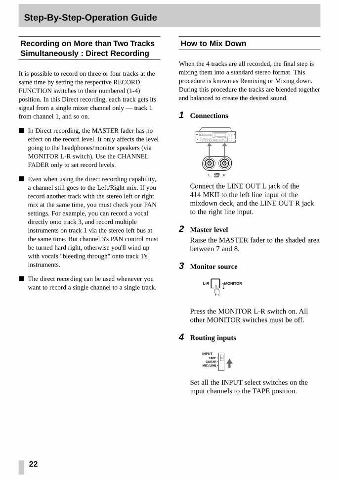
Recording on More than Two TracksSimultaneously : Direct Recording
It is possible to record on three or four tracks at thesame time by setting the respective RECORDFUNCTION switches to their numbered (1-4)position. In this Direct recording, each track gets itssignal from a single mixer channel only — track 1from channel 1, and so on.
In Direct recording, the MASTER fader has noeffect on the record level. It only affects the levelgoing to the headphones/monitor speakers (viaMONITOR L-R switch). Use the CHANNELFADER only to set record levels.
Even when using the direct recording capability,a channel still goes to the Left/Right mix. If yourecord another track with the stereo left or rightmix at the same time, you must check your PANsettings. For example, you can record a vocaldirectly onto track 3, and record multipleinstruments on track 1 via the stereo left bus atthe same time. But channel 3's PAN control mustbe turned hard right, otherwise you'll wind upwith vocals "bleeding through" onto track 1'sinstruments.
The direct recording can be used whenever youwant to record a single channel to a single track.
How to Mix Down
When the 4 tracks are all recorded, the final step ismixing them into a standard stereo format. Thisprocedure is known as Remixing or Mixing down.During this procedure the tracks are blended togetherand balanced to create the desired sound.
1 Connections
Connect the LINE OUT L jack of the 414 MKII to the left line input of themixdown deck, and the LINE OUT R jackto the right line input.
2 Master levelRaise the MASTER fader to the shaded areabetween 7 and 8.
3 Monitor source
Press the MONITOR L-R switch on. Allother MONITOR switches must be off.
4 Routing inputs
Set all the INPUT select switches on theinput channels to the TAPE position.
MONITORL-R
‘

23
Step-By-Step-Operation Guide
5 Playback levelPress PLAY and, while listening to the tapeplay, tentatively set the channel faders.
6 Adjust the PAN controls to set each track'sleft-to- right position for the desired stereoimage. You may also want to use the EQcontrols to adjust the individual tracks forthe desired tonality. (For using effects, seepp. 27 & 28.)
7 Using the MASTER fader, adjust the overallplayback level.
8 ReviewWhen the signal balance, level, and tonalitysound right, rewind the tape, and pressPLAY again to check the result.
9 Rewind the multitrack tape again. Put ablank tape in the mixdown deck and let itplay for 5 seconds, then stop it and reset themixdown deck's counter to zero.
10 Press PLAY on the 414 MKII.
11 Record levelPut the mixdown deck into its "RecordReady" mode, and adjust its input levelcontrols for the desired record level.
12 Rewind the multitrack tape to thebeginning of the recording.
13 Put the mixdown deck into Record modethen press PLAY on the 414 MKII.
14 When recording is done, stop bothmachines, rewind the mixdown tape andlisten to it.
If the mixdown tape does not sound right,make the necessary corrections and re-dofrom the beginning.

24
PUNCH-IN or INSERT Recording
"Punching in" or "insert recording" is recording overa small section of previously recorded track tocorrect or improve a performance, while keeping therest of the track intact. The mixer settings should beexactly the same as they were during the originalrecording.
In the following, we'll use track 2 as the punch-intrack as an example.
Preliminary
1 As the punch-in track is track 2 in ourexample, your input must be sent to thestereo right bus. To do so, rotate the PANcontrol of the channel into which yoursource instrument is plugged all the way tothe right.
2 TAPE CUE signal path is used to hear thetape, so set the master EFFECT 2/TAPECUE select switch to the right/TAPE CUEposition and press the same labeledMONITOR switch on.
3 To hear the instrument, press theMONITOR L-R switch on.
4 Press PLAY to play the tape, adjust theTAPE CUE control on channel 2 to thedesired listening level.
If you want to hear other tracks together,turn up their TAPE CUE controls as well tothe desired level and balance, and adjust theoverall level with the MONITOR control.
5 Play the instrument. You'll hear it togetherwith the tape signals through theheadphones. Stop the tape, and you hearonly the instrument being played.
6 Set the RECORD FUNCTION switch fortrack 2 to R. The track's REC indicator willstart blinking, and meter 2 will show yourinstrument's output level. Adjust the channeland MASTER faders for the properrecording level.
Selecting in and out points
For both musical and technical reasons, whenpunching in or out of a track, you must select pointsthat are "in the points clear", i.e., in pauses betweenphrases or notes. The sound will seem unnatural andinserts will be noticeable if a new note is recordedbefore the old one has ended, or a note is held as youpunch in or out. Making smooth inserts requirespractice. Spacing between the erase and record headsrequires that you anticipate in/out points by afraction of a second for extremely tight cues.

25
PUNCH-IN or INSERT Recording
Punch-in Procedure
There are 2 ways to initiate the punch-in recording.The first is with the transport RECORD button, andthe second is with the optional footswitch.
Perform the "Preliminary" on the previous page, ifyou haven't yet done so.
Punching-in/out with RECORD
1 Check to see that the track 2's RECindicator is blinking showing the track is inthe Rec Ready mode. Locate the tape a littlebehind the expected punch-in point. Thenpress PLAY.
2 When you reach JUST BEFORE the error,hold PLAY and push RECORD. The RECindicator that was blinking will glow solidand track 2 enters the Record mode.
3 To punch-out of record, push STOP (orPAUSE). The REC indicator that was litsolidly blinks to indicate that recording isover.
Using the remote footswitch (RC-30P)
If you are recording alone and are too busy playingan instrument to push the switches, the optionalremote footswitch really comes in handy.
1 Plug the RC-30P into the REMOTEPUNCH IN/OUT jack on the front of the414 MKII.
2 Check that the track 2's REC indicator isblinking, and locate the tape to a point alittle before the error, then press PLAY.
3 When you reach JUST BEFORE the error,press the footswitch, and the REC indicatorthat was blinking will glow steadily toindicate the track is in the Record mode.
4 To punch-out of record, press the footswitchagain. The REC indicator will start blinkingagain.
5 To stop the tape, press STOP.
RC-30P

26
Bouncing Tracks (Ping-Pong)
The recording capability of the PORTASTUDIO 414MKII is not limited to four tracks. You can "bounce"or combine tracks you have recorded to an emptytrack, and then replace the original tracks with newmaterial. A bounce is like a mixdown, except you arerecording to one of the tracks of the 414 MKIIinstead of to an external recorder. The followingdiagrams depict the process.
During a bounce you can add live sources along withthe prerecorded tracks, using the "empty" mixerchannels not being used for tape playback. Thisgives you even more ways to add layers to acomposition. For example, you can bounce tracks1-3 along with another "live" part onto track 4, for atotal of four parts on one track.
Ping-pong Procedure
In this example, we will combine material fromtracks 1-3 onto track 4.
1 On channels 1-3, make the followingsettings :
INPUT to TAPE, PAN all the way to R, and Channel fader to the shaded zone (7-8 on
the scale).
2 Push the MASTER fader to the shadedzone.
3 Press the MONITOR L-R switch on. Theother two MONITOR switches must be off.
TRK 12
34
AB
C
DE
FA + B + C
Bouncing tracks 1-3onto track 4
Tracks 1-3available forrecording new parts
4 Set the RECORD FUNCTION switch fortrack 4 to R. The track 4's REC indicatorwill start blinking, indicating the track is inRec Ready mode.
5 Press PLAY. The tape will start playing.
6 Use channel faders 1 through 3 to make anynecessary level adjustments. You may wantto repeat this step several times to get thebalance correct.
7 When the balance is right and the level ispeaking at no more than +6 on the track 4meter, stop and rewind the tape to thebeginning of the track.
8 Hold RECORD and press PLAY. The RECindicator that was blinking will turn on solidand track 4 will record a copy of what is ontracks 1-3.
9 You'll hear the mix being recorded on track4 in the headphones.
10 Once the recording is done, press STOP(or PAUSE).
11 The REC indicator will now be blinkingas before. Turn that off by setting theRECORD FUNCTION switch for track 4to SAFE.

27
Using Effects with the PORTASTUDIO 414 MKII
Effects and signal processing are areas where youcan really start to have fun customizing your sound,and develop your own unique recording style.Because there are so many possibilities, it also canbe confusing. There are many different effect unitson the market, all with different controls, types ofinputs and outputs, and other characteristics. Readthe manual of your effects device, and the followingsections to get the complete story of what's possiblefor your particular situation.
1. In-line processing: The processing that'seasiest to understand doesn't involve the414 MKII directly at all. You can plug yourinstrument directly into the input of the effectdevice, and plug the output of the device directlyinto a line input of the 414 MKII. The wholesignal gets processed (flanged, doubled, limited,delayed etc.), and only one instrument can usethat processor. Effect pedals for guitar aretypically used this way. To get a mix of processed("wet") and original ("dry") signal, the unit musthave its own MIX or BALANCE control.
2. Send/return mix processing: This is themost common method of effect processing,especially for reverb and delay. It allows anumber of different channels to use the sameeffect, while allowing you to control how mucheffect is mixed with each channel. Each of the 4mixer channels can send signals to the EFFECTSEND 1 or 2 outputs. These outputs can then beconnected to the input of effects devices. Theprocessed signals from the devices are pluggedinto the stereo channels (5-6 and 7-8), for them tobe mixed onto the stereo left and right buses. Thewhole path—from the EFFECT SENDS to thereverb and back into STEREO INPUTS—iscalled an “effects loop”. The EFFECT 1 and 2controls determine how much signal goes to thereverb unit ; the LEVEL control on the stereochannels determines how much returns from thereverb unit. In this method the stereo inputsfunction as effects returns.
Setting Effect Send Levels
The goal is not to distort the device, while stayingabove the noise that effect units generate. To get thebest signal-to-noise from most effects units, youshould send it as strong a signal as you can. With aproperly set input signal in the 414 MKII, thechannel EFFECT send set to about 2 o'clock position(for EFFECT 1 or EFFECT 2 feed), you should get afairly loud signal from the EFFECT SEND jacks.
If your effects device has an input level control of itsown, it should be set so the meter or signal light ofthe effects device is just under the overload point onpeak signals. When you want to hear less effectoverall, turn down the return LEVEL control on thestereo channels.
Setting the Output Level of EffectDevices
If the effect send level has been set properly, in mostcases the output level of the effect unit should be setas high as possible without clipping (distorting) theSTEREO INPUTS of the 414 MKII, but low enoughso that you have a reasonable range of control. Ifyou can get the effect sound you want with thereturn LEVEL control in the 12 to 2 o'clock range,you're in the ballpark. If, on the other hand, verysmall settings of the Effects Return still give you amix drowning in effects, turn down the output levelof your effect device.
Some effect units have rear panel switches settinginput and output level ranges between "+4" and "–20 dB". In this case, try setting the input to –20(high sensitivity) and the output to +4 (full outputlevel).

28
Using Effects with the PORTASTUDIO 414 MKII
Setting the Mix/Balance Control onEffect Devices
When it's being used in a send-return mix, set themix/balance of your effect device all the way to"wet" or full processing with no direct originalsignal. In send/receive processing, the dry signalgoes down the 414 MKII's channel fader to be mixedwith the effect return signal on the stereo mix.Therefore, you don't need any "dry" signal coming tothe effects return. The mix/balance control is settoward "dry" only when you're using the effectsdevice as an in-line processor.
How to Connect Your Effects Devices
There is no absolute "right" or "wrong" way to dothis—there are several ways, each with its ownconsequences.The diagram shows the most commonmethod. EFFECT SEND feeds a reverb unit, whichhas a synthesized stereo output patched intoSTEREO INPUTS 7-8. A special "stereo splitter"cable (such as the optional PW-2Y/4Y) is used, withthe 3-conductor (Tip-Ring-Sleeve) end plugged intochannel 7-8, and the other end split to two 2-conductor plugs connected to the Left and Rightoutputs of the effects unit. If the return is connectedto channel 5-6 and nothing is connected to channel7-8, turn the 7-8 LEVEL control all the way to theleft or else the return is taken into channel 7-8 aswell.
Mono returns: A special feature of the STEREOINPUTS allows continuously variable controlbetween left and right if desired: a mono effectconnected to the 5-6 jack will go to both the LEVELcontrols if nothing is plugged into the 7-8 jack.
Patching effects to an input channel: There'sno law that says the output of an effects device mustbe plugged into STEREO INPUTS. They can also beplugged into LINE INPUTS just like any othersource, if you are cautious about one thing: makesure the EFFECT controls of those channels are setto the off position (turned all the way to the left).Otherwise, you will be sending the output of theeffect device back to itself, which is a kind offeedback. If the effect device is a digital delay,feedback has the same effect as a regeneration(number of echoes) control. An advantage ofreturning effects to a main channel is that you canEQ the effect return.
REVERB
LEFT/MONO RIGHTRIGHT LEFT
INPUTS OUTPUT
R
L
R
L
R
L
R
LMONO
STEREO
Return Signal L/MONO Jack OnlyConnected (R Jack Empty) L/MONO and R Jacks Both Connected

3029
Syncing MIDI-Tape — Using the TASCAM MTS-30 Troubleshooting
Problem Possible Cause
Playback sounds dull Dirty heads
Playback level is too low Dirty heads
Transport keys not effective Power turned off, or tape not loaded
No recording RECORD FUNCTION set to SAFE, or cassette tab broken
Wrong tracks recorded PAN improperly set
Incorrect playback pitchPITCH CONTROL set to a different position than during recording
Feedback occurs during ping-pong Level is too high or EQ HIGH is excessively boostedrecording
Problem Solution
Old tracks are always recorded along Use the TAPE CUE section instead of the main mixer for with new material monitoring previous tracks
Make sure that all mixer channel faders are turned down to the minimum level except the ones that you are using. Also,
Recording is noisy increase the volume controls of the instruments you are recording — the 414 MKII channel and master faders should not have to be "full up" at any time
Incorrect tape syncTry re-recording sync tones by adjusting the channel faderso that the track 4 meter reads between –10 dB and 0 dB
MIDI clocks are themselves a computer type digitallanguage and cannot be recorded on analog tape; it isnecessary to convert them to recordable FSK(Frequency Shift Keying) signals using an appropri-ate converter, such as the MTS-30.
The MTS-30 is not a mere MIDI-FSK converter buttranslates MIDI clocks into an FSK sync signal con-taining score "bar" information or "Song PositionPointer", allowing the associated MIDI equipment tostay in sync and follow the tape no matter where youmove the tape within a given song. The maximumstability or resolution of the synchronization isensured by a TASCAM-exclusive error correctioncircuit in the MTS-30.
1 Connect the TAPE OUT of the MTS-30 to theSUB IN "R" of the 414 MKII, and the SYNCOUT of the 414 MKII to the TAPE IN of theMTS-30.
2 Set the track 4's RECORD FUNCTION switchto R.
3 Set the DBX switch on the 414 MKII to theSYNC position. This defeats the dbxencode/decode for track 4 only.
– When recording FSK signals, adjust the MAS-TER fader of the 414 MKII to get a reading onthe track 4 meter of from –10 to 0 dB.

31 32
Features and Controls
414 MKII MIXER
1. POWER switch (on the rear panel): Turnsthe 414 MKII on and off.
2. DC IN 12 V connector (on the rear panel):This is for connection of the provided TASCAMPS-P414 AC adaptor only.
3. MIC/LINE IN jacks (Channels 1-4): These1/4" jacks accept unbalanced signals rangingfrom –50 dBV (3 mV) to –10 dBV (0.3 V),depending on the setting of the TRIM control(#13).
4. INPUT L & R (on the rear panel): TheseXLR-type connectors accept balanced signals.They are mainly intended for use with dynamicmicrophones, but the nominal input level may beadjusted from –60 to –20 dBV depending on thesetting of the TRIM control. Note that if a signalsource is connected to the front MIC/LINE INjack corresponding to the XLR-type connectorwhere a microphone is connected (L=1 or 3, R=2or 4), the signal input here at the INPUT (L/R)connector will be ignored by the 414 MKII.
5. GUITAR IN & TRIM control (on the rearpanel): This 1/4" jack has an impedance of1MΩ and is intended for use with electric gui-tars, basses, etc. Adjust the gain from this jack tochannels 1 - 4 with the TRIM control here (turn-ing it clockwise increases the signal level).
6. SUB IN L and R jacks: These jacks are forcascade connection of an outboard mixer, etc.The signal input to these jacks is sent to theMASTER fader. Nominal input level is –10 dBV(0.3 V).
The SUB IN R jack is also used to accept FSK-converted MIDI sync signals from devices suchas the optional TASCAM MIDI-TapeSynchronizer MTS-30.
7. EQ HIGH: These control the tonality of the highor "treble" frequencies. Turn them to the right toboost the signal's high frequency content empha-sizing brilliance or brightness. Turn them to the
Input Section
left to cut the high frequency content, if the sig-nal sounds too harsh or shrill. The EQ shelvingpoint is 10 kHz.
8. EQ LOW: Turn the controls to the right to boostbass frequencies and make the sound relativelyheavy. Turn the controls to the left to cut bassand make the sound thinner. The EQ shelvingpoint is 100 Hz.
9. EFFECT 1 send controls: These controls gettheir signal from a point just after the channelfader (i.e., "post fader send") and route the corre-sponding channel signal to the EFFECT 1 SENDjack. Turn the control to the right to increase vol-ume to the EFFECT 1 SEND jack.
10. EFFECT 2/TAPE CUE controls: These con-trols get their signal after the channel fader androute the signal to the EFFECT 2 SEND jack, orare used to adjust the tape playback level sent tothe monitor section, as determined by theEFFECT 2/TAPE CUE select switch (#19).
11. PAN controls: These controls allow you tocreate stereo mixes by sending the signal fromthe channel fader in continuously variabledegrees to the left or right sides of the stereo mixat mixdown time.
12. INPUT select switches: These are used tocontrol what the source of the channel is:
The upper position (TAPE) is used during mix-down or bouncing tracks.
The center position is GUITAR, which selects thesource at the GUITAR IN jack (#5).Turn the guitar TRIM control all the way to theleft.
The lower position (MIC/LINE) is used whenrecording microphones/instruments (in trackingor overdubbing).
13. TRIM controls: These linear controls are usedto set the preamplification level on theMIC/LINE IN(puts) or INPUT (L, R). WhenTRIM is pulled full down, the preamplifier gainis low, allowing the jack to accept line levelsources such as electronic instruments. As youpush TRIM up, the preamplifier gain increases,and when you push TRIM full up, the nominalinput sensitivity increases to –50 dBV (3 mV).
145 2
6 21 22 23 24 25 16 15
40
7
89
411039
11
12
13
14
3 26 38 20 29 30 31 32 33 34
28
35
363717
1819
27
–
– – – –
–
–
–
–
–
–
–
–
–
–
–
–
–
–
–
–
–
–
–
– – –
– –
–
–
–
–
– – – – – –
––
– – – –
–
–
––––––– ––
––––––
––––––––
––

33
Features and Controls
14. Channel faders: These linear controls vary thelevel feeding the Master section.
The nominal setting position is between 7 and 8(shaded area).
15. STEREO INPUTS (Ch.5-6/7-8): Connect theoutputs of your effects devices to these 1/4"jacks.
These jacks can also be used as additional lineinputs. Nominal input level is –10 dBV (0.3 V).
See also "How to Connect Your EffectsDevices", p.28.
16. LEVEL controls: These rotary controls varythe level feeding the Master section.
The nominal setting position is about 2 o’clock.
17. MONITOR level control: This affects signalfrom the MONITOR switches and sets the levelyou'll hear in the headphones/monitor speakers.
18. MONITOR switches: Used to select a signalor signals to send to the PHONES and MONOUT jacks. When the L-R switch is on, the leftmix is heard on the left side, and the right mixon the right side. The EFFECT 1 switch allowsyou to check the channel signal going to thecorresponding send jack. The third switch isused to check the channel signal going to theEFFECT 2 SEND jack or the signal from therecorder, depending on the setting of the switchwith the same label located to the right of thetrack 4 meter.
19. EFFECT 2/TAPE CUE select switch:Depending on the setting of this switch, eachchannel's EFFECT 2/TAPE CUE control isswitched to send the MIC/LINE input to effectsdevices or the signal coming back from therecorder to the musicians in the studio.
Master Section
Monitor Section
Stereo Input Section
20. MASTER fader: Used to adjust the stereo mixlevel. The signal fed to this fader comes fromeach channel's PAN control. The safe operatingzone is between 7-8 on the scale.
21. SYNC OUT jack: Sync tones recorded on trackis sent out of this jack, for MIDI instruments toplay synced up to the tape. See also the section,Syncing MIDI-Tape.
22. LINE OUT L and R jacks: These jacks are theline-level outputs from the MASTER fader. TheL and R jacks are typically connected to your 2-track master recorder at MIXDOWN. The LINEOUT jacks can also be used to send the mixeroutputs of the 414 MKII to the sub inputs of alarger mixer.
23. MON OUT L and R jacks: These provide aline level version of the same signal that feedsthe PHONES jack and may be connected to yourcontrol room speaker amplifier.
24. EFFECT 1 SEND jack: The signal available atthis jack comes from post-fader, for connectionto effects devices. Nominal level is –10 dBV(0.3 V).
25. EFFECT 2 SEND /TAPE CUE OUT jack:This jack is for connection to an additionaleffects device, or to a studio speaker amplifier.The signal source is determined by the EFFECT2/TAPE CUE select switch (#19). Nominaloutput level is –10 dBV (0.3 V).
26. PHONES jack (on the front panel):Connect any stereo headphones with a 1/4"stereo TRS 3-conductor plug to this jack.
Output Section

34
Features and Controls
414 MKII RECORDER
27. Cassette compartment door: To insert orremove a cassette, pull the door open. Once acassette is inserted, be sure to close the door toprevent objects, dust or liquids from falling intothe tape path.
Tape path components
28. DBX switch : When this switch is set to its ONposition, the built-in dbx noise reduction systemfor all 4 tracks is turned on. This is the normalposition for all recording and playback.
When it is set to the SYNC position, Track 4 isdisconnected from the dbx system, so theprocess does not affect the sync signals going toand from track 4, but tracks 1-3 still go throughthe dbx encode/decode process. Use the SYNCposition for recording and playback of FSKsync or SMPTE time code.
The OFF position turns off the dbx noisereduction completely. Use this position whenplaying back tapes made with no noisereduction.
The dbx NR system provides a net noisereduction (broadband, not just hiss) of about 30 dB, and also permits a net gain in tapeheadroom of about 10 dB, allowing recordingsover a 90 dB dynamic range.
29. RECORD key : Pressing this key alone has noeffect. Pressing it together with PLAY (í)activates recording if one or more RECORDFUNCTION switches are previously set to adifferent position from SAFE and the RECindicators blink.
Transport Controls
Erase headRecord/Play head Pinch roller
Capstan
Cassette Loading and dbx System
30. PLAY key:
a) Press this key alone to start playback.
b) If pressed together with RECORD, recording("punch in") starts.
31. REW key: Winds tape at high speed in reversedirection.
32. F FWD key: Winds tape at high speed in theforward direction.
33. STOP key: Stops any tape motion and disablesall transport modes.
34. PAUSE key: Temporarily stops play orrecording. To resume the function interrupted,press PAUSE off.
35. PITCH CONTROL dial: Varies tape speed inrecord and play modes by up to approximately±10%. Turn the dial to the left to lower thespeed, or to the right to increase the speed. Setthe dial to the center "0" position to run tape at astandard speed of 9.5 cm/sec.
This can be used to save slightly out-of-tuneparts, or to create sound effects such asflanging.
CAUTION: The PITCH CONTROL dial affectsrecording speed also. Check to make sure thatthe dial is at its center "0" position unless youare using the function intentionally.
36. Tape counter: Displays the distance the tapehas moved from a zero reference point selectedby pressing the adjacent button.
37. ZERO RETURN switch: When this switch isset to ON, and you press REW, the tape will stopat the counter 000 point. If the tape overshoots,it is because of inertia, and it is normal.
The associated LED blinks to show that the tapeis on its way to the counter zero point. Whenthis point is reached the LED lights solidly.

35
Features and Controls Care and Maintenance
38. REMOTE PUNCH IN/OUT jack (on thefront panel): For connection to an optionalRC-30P remote footswitch.
39. RECORD FUNCTION switches 1-4: Theseswitches put the respective tracks into RecordReady. Recording starts when RECORD ispressed together with PLAY.
In the center position (SAFE) no recordingtakes place.
NOTEDon't operate the RECORD FUNCTIONswitches to punch in and out. Otherwise,"clicks" will remain on tape.
The RECORD FUNCTION switches also selectwhat source will be recorded. For example, theswitch for track 1 selects either the singlesource plugged into Channel 1 of the mixer, orthe entire stereo Left mix (which may have asmany as six sources). The other RECORDFUNCTION switches work in the same way,selecting either the same-numbered channels orthe stereo mix : Left mix for Tracks 1 & 3,Right mix for Tracks 2 & 4.
40. Track level meters 1-4: These meters showthe record level coming either from eachchannel's fader or from the MASTER fader (thefirst and the third meters register the level fromthe left buss, the second and the fourth metersregister the level from the right buss). If a trackor tracks are in Safe mode the correspondingmeters show the playback level.
41. Track REC indicators: They show theindividual track's status as selected by theRECORD FUNCTION switches (#39).
Track REC indicator Track status
Off Safe
Blinking Record Ready
Steady indication Record
Displays
Track Controls Even though the heads used in your 414 MKII havehigh wear resistance and are rigidly constructed,performance degradation or electro-mechanicalfailure can be prevented if maintenance is performedregularly.
CLEANING
The first things you will need for maintenance arenot expensive. The whole kit with the swabs andfluids you will need for months will cost less than acouple of high quality cassettes.
We cannot stress the importance of cleaning toomuch. Clean up before each session. Clean up afterevery session. Clean up every time you take a breakin the middle of a session.
DEGAUSSING (DEMAGNETIZING)
A little stray magnetism can become quite a bignuisance in tape recording. It only takes a smallamount (0.2 Gauss) to cause trouble on the recordhead. Playing 10 cassettes will put about that muchcharge on the heads. A little more than that (0.7Gauss) will start to erase high frequency signals onpreviously recorded tapes. You can see that it's worthtaking the trouble to degauss regularly.
A clean and properly demagnetized tape recorderwill maintain its performance without any otherattention for quite a while. It won't ruin previouslyrecorded material, nor will getting it back to originalspecifications be difficult.
Cleaning the Heads and Tape Guides
All heads and metal parts in the tape path must becleaned after every 6 hours of operation, or beforestarting and after ending a recording session.
1. Open the cassette door.
2. Using a good head cleaning fluid and a cottonswab, clean the heads and tape guides until theswab comes off clean, wipe off any excesscleaning fluid with a dry swab.

36
Care and Maintenance How the dbx Works
Cleaning the Pinch Roller
Clean the pinch roller at least once each day the deckis used. Use a good rubber cleaner.
1. Clean the pinch roller with a cotton swabmoistened with rubber cleaner, until there is novisible residue on the pinch roller.
2. Using a clean cotton swab, wipe off all excessrubber cleaner from the pinch roller. Make certainthat there is no foreign matter remaining on thepinch roller.
Cleaning the Capstan Shaft
After cleaning the pinch roller, clean the capstanshaft with a cotton swab moistened with headcleaning fluid.
Degaussing the Tape Path
Hold the degausser about 1 m (3 feet) away from therecorder. Turn it on, slowly move into the tape path.Move the degausser slowly back and forth, touchinglightly all metal parts in the tape path. Slowly move itaway again to at least 1 m (3 feet) from the recorderbefore turning it off.
CAUTIONIf the surface of the unit gets dirty, wipe thesurface with a soft cloth or use a dilutedneutral cleaning fluid. Clean off thoroughly.Do not use thinner, benzine, or alcohol, asthey may damage the surface of the unit.
Erase head
Record/Play head Pinch roller
Capstan
The dbx system is a wide-band compression-expansion system which provides a net noisereduction (broadband, not just hiss) of a little morethan 30 dB. In addition, the compression duringrecording permits a net gain in tape headroom ofabout 10 dB.
A compression factor of 2:1 is used before recording;then, 1:2 expansion on reproduce. Thesecompression and expansion factors are linear indecibels and allow the system to produce taperecordings with over a 90 dB dynamic range – animportant feature, especially when you're makinglive recordings. The dbx system employs RMS levelsensors to eliminate compressor-expander trackingerrors due to phase shifts in the tape recorder, andprovides excellent transient tracking capabilities.
To achieve a large reduction in audible tape hiss,without danger of overload or high-frequency self-erasure on the tape, frequency pre-emphasis and de-emphasis are added to the signal and RMS levelsensors.
SUBSONICS AND INTERFERENCE
The dbx system incorporates an effective bandpassfilter. This filter suppresses undesirable subsonicfrequencies to keep them from introducing errorsinto the encode or decode process. However, ifrumble from trains or trucks is picked up by yourmicrophone and fed to the dbx system, modulationof the program material during low level passagesmay occur. This low-frequency component will notitself be passed through the recorder and so, will notbe present at reproduce for proper decoding. If thislow-level decoding error is encountered, andsubsonics are suspected, we suggest the addition of asuitable high-pass filter in the microphone line.
80dB
Input
Dynamic rangeof
input signal
Encoder Tape deck Decoder Output
Encode(Compress)
40dB 40dBRecord Playback
Decode(Expand)
80dB Saturationlevel
+20dB
+10dB+15dB
+25dB+20dB
0dB
Dynamic range of tape(65dB)
–60dB–60dB
–30dB
–50dB
–80dB Noise level dbx encoding/decoding level diagram
Á Á ÁÁ
Á
ÁÁÁ
3837
Specifications
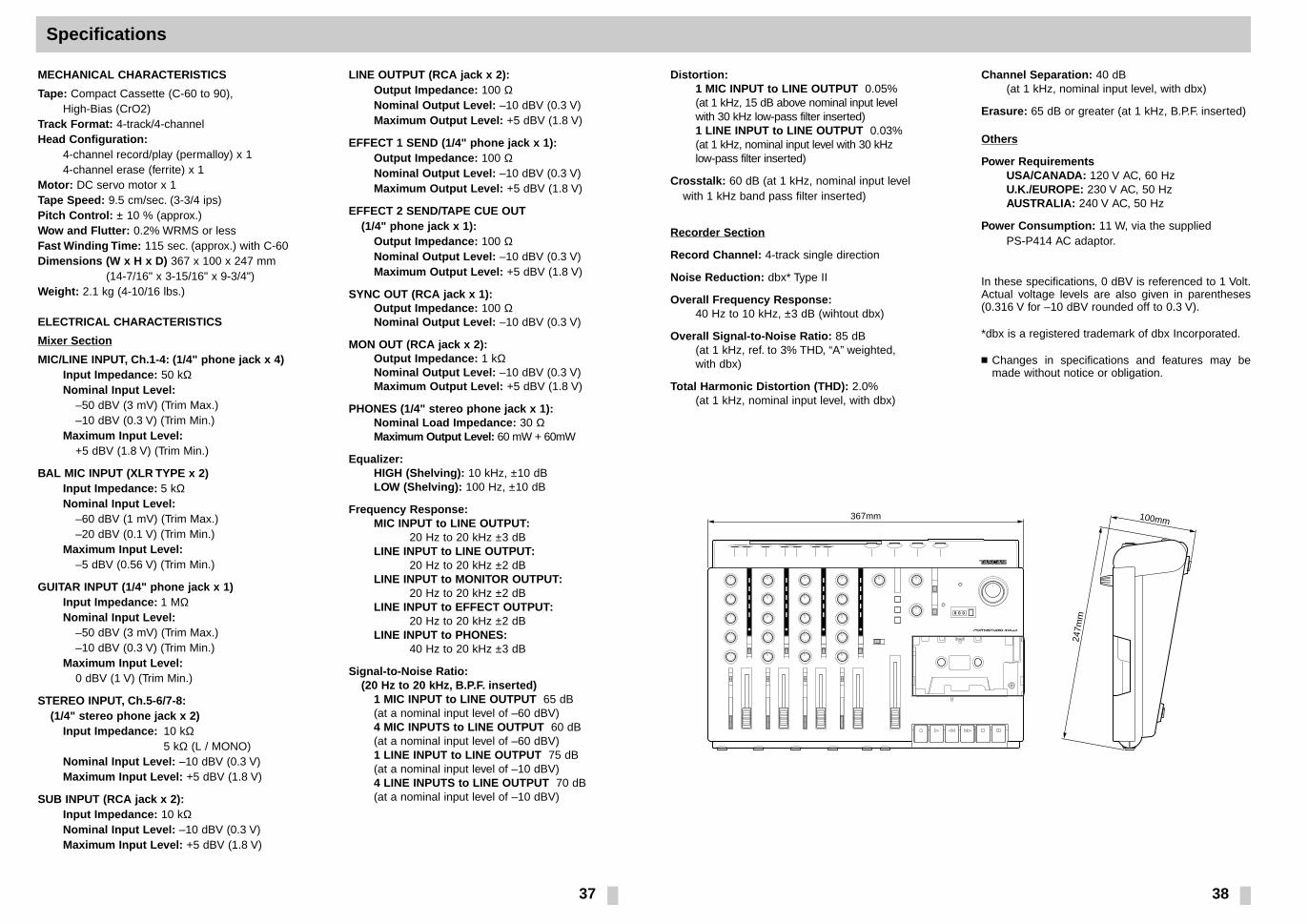
MECHANICAL CHARACTERISTICS
Tape: Compact Cassette (C-60 to 90), High-Bias (CrO2)
Track Format: 4-track/4-channelHead Configuration:
4-channel record/play (permalloy) x 14-channel erase (ferrite) x 1
Motor: DC servo motor x 1Tape Speed: 9.5 cm/sec. (3-3/4 ips) Pitch Control: ± 10 % (approx.)Wow and Flutter: 0.2% WRMS or lessFast Winding Time: 115 sec. (approx.) with C-60Dimensions (W x H x D) 367 x 100 x 247 mm
(14-7/16" x 3-15/16" x 9-3/4")Weight: 2.1 kg (4-10/16 lbs.)
ELECTRICAL CHARACTERISTICS
Mixer Section
MIC/LINE INPUT, Ch.1-4: (1/4" phone jack x 4)Input Impedance: 50 kΩNominal Input Level:
–50 dBV (3 mV) (Trim Max.)–10 dBV (0.3 V) (Trim Min.)
Maximum Input Level:+5 dBV (1.8 V) (Trim Min.)
BAL MIC INPUT (XLR TYPE x 2)Input Impedance: 5 kΩNominal Input Level:
–60 dBV (1 mV) (Trim Max.)–20 dBV (0.1 V) (Trim Min.)
Maximum Input Level:–5 dBV (0.56 V) (Trim Min.)
GUITAR INPUT (1/4" phone jack x 1) Input Impedance: 1 MΩNominal Input Level:
–50 dBV (3 mV) (Trim Max.)–10 dBV (0.3 V) (Trim Min.)
Maximum Input Level:0 dBV (1 V) (Trim Min.)
STEREO INPUT, Ch.5-6/7-8:(1/4" stereo phone jack x 2)
Input Impedance: 10 kΩ5 kΩ (L / MONO)
Nominal Input Level: –10 dBV (0.3 V)Maximum Input Level: +5 dBV (1.8 V)
SUB INPUT (RCA jack x 2):Input Impedance: 10 kΩNominal Input Level: –10 dBV (0.3 V)Maximum Input Level: +5 dBV (1.8 V)
LINE OUTPUT (RCA jack x 2):Output Impedance: 100 ΩNominal Output Level: –10 dBV (0.3 V)Maximum Output Level: +5 dBV (1.8 V)
EFFECT 1 SEND (1/4" phone jack x 1):Output Impedance: 100 ΩNominal Output Level: –10 dBV (0.3 V)Maximum Output Level: +5 dBV (1.8 V)
EFFECT 2 SEND/TAPE CUE OUT(1/4" phone jack x 1):
Output Impedance: 100 ΩNominal Output Level: –10 dBV (0.3 V)Maximum Output Level: +5 dBV (1.8 V)
SYNC OUT (RCA jack x 1):Output Impedance: 100 ΩNominal Output Level: –10 dBV (0.3 V)
MON OUT (RCA jack x 2):Output Impedance: 1 kΩNominal Output Level: –10 dBV (0.3 V)Maximum Output Level: +5 dBV (1.8 V)
PHONES (1/4" stereo phone jack x 1):Nominal Load Impedance: 30 ΩMaximum Output Level: 60 mW + 60mW
Equalizer:HIGH (Shelving): 10 kHz, ±10 dBLOW (Shelving): 100 Hz, ±10 dB
Frequency Response:MIC INPUT to LINE OUTPUT:
20 Hz to 20 kHz ±3 dBLINE INPUT to LINE OUTPUT:
20 Hz to 20 kHz ±2 dBLINE INPUT to MONITOR OUTPUT:
20 Hz to 20 kHz ±2 dBLINE INPUT to EFFECT OUTPUT:
20 Hz to 20 kHz ±2 dBLINE INPUT to PHONES:
40 Hz to 20 kHz ±3 dB
Signal-to-Noise Ratio:(20 Hz to 20 kHz, B.P.F. inserted)
1 MIC INPUT to LINE OUTPUT 65 dB (at a nominal input level of –60 dBV)4 MIC INPUTS to LINE OUTPUT 60 dB(at a nominal input level of –60 dBV)1 LINE INPUT to LINE OUTPUT 75 dB(at a nominal input level of –10 dBV)4 LINE INPUTS to LINE OUTPUT 70 dB(at a nominal input level of –10 dBV)
Distortion:1 MIC INPUT to LINE OUTPUT 0.05% (at 1 kHz, 15 dB above nominal input level with 30 kHz low-pass filter inserted)1 LINE INPUT to LINE OUTPUT 0.03%(at 1 kHz, nominal input level with 30 kHz low-pass filter inserted)
Crosstalk: 60 dB (at 1 kHz, nominal input level with 1 kHz band pass filter inserted)
Recorder Section
Record Channel: 4-track single direction
Noise Reduction: dbx* Type II
Overall Frequency Response:40 Hz to 10 kHz, ±3 dB (wihtout dbx)
Overall Signal-to-Noise Ratio: 85 dB (at 1 kHz, ref. to 3% THD, “A” weighted, with dbx)
Total Harmonic Distortion (THD): 2.0% (at 1 kHz, nominal input level, with dbx)
Channel Separation: 40 dB (at 1 kHz, nominal input level, with dbx)
Erasure: 65 dB or greater (at 1 kHz, B.P.F. inserted)
Others
Power RequirementsUSA/CANADA: 120 V AC, 60 HzU.K./EUROPE: 230 V AC, 50 HzAUSTRALIA: 240 V AC, 50 Hz
Power Consumption: 11 W, via the supplied PS-P414 AC adaptor.
In these specifications, 0 dBV is referenced to 1 Volt.Actual voltage levels are also given in parentheses(0.316 V for –10 dBV rounded off to 0.3 V).
*dbx is a registered trademark of dbx Incorporated.
Changes in specifications and features may bemade without notice or obligation.
367mm 100mm
247m
m

39 40
Block Diagram
LINE OUT(-10dBV)
L
R
MONITOR
(-10dBV)
(-10dBV)
EFFECT 1 SEND
EFFECT 2 SEND/TAPE CUE OUT
ATT
PHONES
(60mW+60mW)
MONITOR OUT(-10dBV)
L/R
EFFECT 1
L
SAFE
SAFE
SAFE
SAFE
1
R
2
L
TRK1
TRK2
EFFECTF 2/TAPE CUE
L
R
LED METER
3
R
4
TRK3
TRK4
RECORD FUNCTION
4TRK 4CH R/P AMP DBX TYPE 2 NR
TRK1 TRK2 TRK3 TRK4
TAPE1
TAPE2
TAPE3
TAPE4
DBX UNIT
REC 1
REC 2
REC 3
REC 4
SYNC
DBX
DBX
SYNC
ON
OFF
PAN L
R
EFFECT 1
INPUTFADER
TRIM
INPUT
MIC/LINE
GUITAR IN
TAPE
(-50 to -10dBV)
MIC/LINE 1
MIC/LINE 2
(-50 to -10dBV)
MIC/LINE 3
(-50 to -10dBV)
TO: CH 2
TO: CH 3
TO: CH 2
TO: CH 3
LOW HIGH
DIRECT 1
DIRECT 2
DIRECT 3
TAPE CUE
EFFECT 2
EFFECT 2/TAPE CUE
DIRECT 4
TAPE 1
TAPE 2
TAPE 3
TAPE 4CH 1 - CH 4
TO: CH 4 TO: CH 4
MIC/LINE 4
(-50 to -10dBV)
INPUT L
(-60 TO -20dBV)
INPUT R
(-60 TO -20dBV)
(-10dBV)
(-10dBV)
STEREO INPUTS 5-6
STEREO INPUTS 7-8
LEVEL 5-6
L
R
SUB IN
(-10dBV)TRIM
GUITAR IN
(-50 to -10dBV)
TRK 1
TRK 2
R/P HEADTRK 3
TRK 4
TRK 1
TRK 2
TRK 3
TRK 4
REMOTE PUNCH I/O
(RC-30P used)
ERASE HEAD
EQ
MASTER
L R EFF
EFF2/TAPE
CUE
LEVEL 7-8
RINGTIP
STEREO JACK
MONO JACK : L/MONO
R
STEREO JACK
MONO JACK :
: L: R
RINGTIP : R
: L
SYNC OUT

41
Level Diagram1
2
109
37
8
456
TR
K 2
TR
K 3
TR
K 4
TR
K 1
RE
PR
OE
Q A
MP
RE
C/R
EP
RO
HE
AD
RE
C
RE
PR
O
RE
CE
Q A
MP
BIA
SA
DJ.
ER
AS
EH
EA
D
TR
AP
BIA
SA
MP
RE
CM
UT
ER
EC
LEV
EL
85kH
z O
SC
EN
C O
UT
IN DE
C O
UT
PLA
YM
UT
E
dbx
NR
RE
PR
OLE
VE
L
EQ
LPF
RE
C IN
TA
PE
OU
T
RE
C IN
TA
PE
OU
T
RE
C IN
TA
PE
OU
T
RE
C IN
TA
PE
OU
T
5
( dB
V )
0 dB
V =
1.0
Vrm
s
+10
0
–10
–20
–30
–40
–50
–60
–70
–80
–90
(–21
)(–
18)
(–79
)(3
15H
z 16
0nW
b/m
)
RE
PR
OH
EA
D
1
34
2
TA
PE
OU
T
(–10
)
(–18
)
(–21
)
(–28
)
(–38
)R
EC
HE
AD
67
8
9
10
RE
C IN
+10
dB
–10d
B
0 dB
V =
1.0
Vrm
s
CH
1 –
CH
4
TA
PE
IN(d
BV
) 0
–10
–20
–30 0
–10
–20
–30
–40
–50
–60
–70
(dB
V)
(dB
V) 0
–10
–20
–30
(dB
V) 0
–10
–20
–30
(dB
V) 0
–10
–20
–30
(–10
)
MIC
/LIN
E IN
(–10
)LI
NE
(–1
0)
MIC
(–5
0)
BA
L
TR
IM
0
–10
–20
–30
–40
–50
–60
(dB
V)
GU
ITA
R IN
(–10
)
TR
IM
INP
UT
FA
DE
R
+10
dB
–10d
B
EQ
LOW
EQ
HIG
H
(–10
)
(–10
)
(–18
) (–18
)
CH
5 –
CH
8
ST
ER
EO
INP
UT
S
SU
B IN
LEV
EL
(–18
)
(–10
)
(–18
)
(–26
)
MA
ST
ER
EF
FE
CT
1, 2
TA
PE
CU
E
0
–10
–20
–30
–40
(dB
V)
(–10
)
(–18
)
(–10
)
MO
NIT
OR
(–10
)
(–10
)
LIN
E O
UT
MO
N O
UT
EF
FE
CT
1 S
EN
DE
FF
EC
T 2
SE
ND
/ T
AP
E C
UE
OU
T
SY
NC
OU
T(–
10)
TR
IM

TEAC CORPORATIONPhone: (0422) 52-5082 3-7-3, Nakacho, Musashino-shi, Tokyo 180-8550, Japan
TEAC AMERICA, INC.Phone: (323) 726-0303 7733 Telegraph Road, Montebello, California 90640
TEAC CANADA LTD.Phone: 905-890-8008 Facsimile: 905-890-9888 5939 Wallace Street, Mississauga, Ontario L4Z 1Z8, Canada
TEAC MEXICO, S.A. De C.VPhone: 5-658-1943 Privada De Corina, No.18, Colonia Del Carmen Coyoacon, Mexico DF 04100
TEAC UK LIMITEDPhone: 01923-819699 5 Marlin House, Marlins Meadow, The Croxley Centre, Watford, Herts. WD1 8YA, U.K.
TEAC DEUTSCHLAND GmbHPhone: 0611-71580 Bahnstrasse 12, 65205 Wiesbaden-Erbenheim, Germany
TEAC FRANCE S. A.Phone: 01.42.37.01.02 17 Rue Alexis-de-Tocqueville, CE 005 92182 Antony Cedex, France
TEAC BELGIUM NV/SAPhone: 0031-30-6048115 P.A. TEAC Nederland BV, Perkinsbaan 11a, 3439 ND Nieuwegein, Netherlands
TEAC NEDERLAND BVPhone: 030-6030229 Perkinsbaan 11a, 3439 ND Nieuwegein, Netherlands
TEAC AUSTRALIA PTY., LTD. A.C.N. 005 408 462Phone: (03) 9644-2442 106 Bay Street, Port Melbourne, Victoria 3207, Australia
TEAC ITALIANA S.p.A.Phone: 02-66010500 Via C. Cantù 11, 20092 Cinisello Balsamo, Milano, Italy
PRINTED IN CHINA 0799 M-1531A
»414@#