Embed Size (px)
Citation preview

Document No.: 4100-M004 June 1997 Issue 1.0
4120 NETWORK FIRE INDICATOR PANEL
2500 NETWORK DISPLAY UNIT(NDU)
OPERATOR MANUAL (LT0290)

Page ii SIMPLEX 4120 NETWORK FIRE INDICATOR PANELOPERATOR MANUAL
Document No.: 4100-M004 June 1997 Issue 1.0
GLOSSARY OF STANDARD TERMS
The following abbreviations are used throughout this manual:
ACF: Ancillary control facility.
"Ackd": Display abbreviation for acknowledged condition.
AVF: Alarm Verification Facility.
ALM: Display abbreviation for alarm condition.
AS1668: Australian Standard AS1668 specifying the use of mechanicalventilation and air-conditioning in buildings.
FIP: Fire Indicator Panel.
"Isol": Display abbreviation for Isolated condition.
LCD: Liquid Crystal Display.
LED: Light Emitting Diode.
MANUFACTURERS DETAILS
APPROVALS: AUSTRALIAN STANDARD AS1603.4SSL CERTIFICATE OF COMPLIANCE NUMBER 127
The 4100 Fire Indicator Panel is manufactured by:
Simplex International Time Equipment Pty Ltd140 Old Pittwater Road
Brookvale N.S.W 2100 Australia
Phone: (02)-9466-2333
Notice: The contents of this document is subject to change without notice.

SIMPLEX 4120 NETWORK FIRE INDICATOR PANEL Page iiiOPERATOR MANUAL
Document No: 4100-M004 June 1997 Issue 1.0
TABLE OF CONTENTS
COMPATIBLE ACTUATING DEVICES ................................................................... vii
SIMPLEX RANGE:....................................................................................................... viiHOCHIKI RANGE: CONVENTIONAL DETECTORS......................................................... viiOLSEN RANGE: CONVENTIONAL DETECTORS .......................................................... viiiAPOLLO: CONVENTIONAL DETECTORS...................................................................... viiiPANELECT/PANASONIC: CONVENTIONAL DETECTORS .......................................... viii
COMPATIBLE BATTERIES...................................................................................... ix
SPECIFICATION........................................................................................................ x
GENERAL......................................................................................................................xEXPANSION MODULES................................................................................................xINDICATORS AND DISPLAY.........................................................................................xiKEYPAD CONTROLS...................................................................................................xiSOFTWARE FEATURES .............................................................................................xii
SECTION 1 - SYSTEM OVERVIEW .......................................................................... 1
1.1 INTRODUCTION TO NETWORKING.......................................................................11.2 SYSTEM INTRODUCTION.......................................................................................2
1.2.1 4120 Fire Indication Panel ..............................................................................21.2.2 2500 Network Display Unit..............................................................................31.2.3 2500 NDU with Status Command Centre .......................................................4
1.3 SYSTEM OPERATING DESCRIPTION....................................................................41.3.1 Operator Log In/Log Out Procedures .............................................................5
1.3.1.1 Access Level Log-In Procedure.................................................................... 61.3.1.2 Access Level Log Out Procedure................................................................. 7
1.3.2 HANDLING ABNORMAL CONDITIONS.........................................................71.3.2.1 The <DISPLAY TIME> Key............................................................................. 9
SECTION 2 - ALARM CONDITIONS ....................................................................... 10
2.1 GLOBAL ACKNOWLEDGE OPERATION DURING ALARM CONDITIONS ......... 102.2 INDIVIDUAL ACKNOWLEDGE DURING ALARM CONDITIONS......................... 122.3 ESSENTIAL ALARM CONDITION KEYS .............................................................. 13
2.3.1 Alarm Ack (Acknowledge)............................................................................. 132.3.2 System Reset ............................................................................................... 13
2.4 HOW TO ISOLATE / DE-ISOLATE A ZONE.......................................................... 142.5 HOW TO ISOLATE / DE-ISOLATE INDIVIDUAL DEVICES................................... 16
2.5.1 Disabling Individual Points/Devices .............................................................. 162.5.2 Enabling Individual Points/Devices ............................................................... 17
SECTION 3 - FAULT CONDITIONS ........................................................................ 19
3.1 GLOBAL ACKNOWLEDGE OPERATION DURING FAULT CONDITIONS........... 193.2 INDIVIDUAL ACKNOWLEDGE OPERATION DURING FAULT CONDITIONS ..... 203.4 ESSENTIAL FAULT CONDITION KEYS................................................................ 21
3.4.1 Fault Acknowledge Key ................................................................................ 213.4.2 System Reset to Clear Faults ....................................................................... 22

Page iv SIMPLEX 4120 NETWORK FIRE INDICATOR PANELOPERATOR MANUAL
Document No.: 4100-M004 June 1997 Issue 1.0
3.5 FAULT INDICATIONS FOR TRUEALARM™ SENSORS.......................................... 223.5.1 Dirty Fault Indication.................................................................................... 223.5.2 Excessively Dirty Fault Indication.................................................................. 233.5.3 Self Test Abnormal Fault Indication .............................................................. 23
SECTION 4 - RS-232 INTERFACE.......................................................................... 24
4.1 RS-232 PORT ACCESS LEVELS.......................................................................... 244.2 THE VIDEO TERMINAL......................................................................................... 24
4.2.1 CRT Function Key Definitions....................................................................... 254.2.2 Set-Up Procedure......................................................................................... 25
4.3 CRT SCREEN DISPLAYS...................................................................................... 254.3.1 CRT Main Menu Screen ............................................................................... 264.3.2 Acknowledge Screen.................................................................................... 264.3.3 Log In Screen ............................................................................................... 274.3.4 Historical Log Screen ................................................................................... 284.3.5 Status Screen............................................................................................... 29
4.4 THE SYSTEM PRINTER ........................................................................................ 30
SECTION 5 - MAPNET II® ....................................................................................... 31
5.1 MAPNET II® ALPHANUMERIC DISPLAYS............................................................ 315.2 MAPNET II® POINT ADDRESSING........................................................................ 31
5.2.1 How to Display a MAPNET II® System Point................................................. 315.2.2 What To Do If a MAPNET II® Point Will Not Reset ....................................... 31
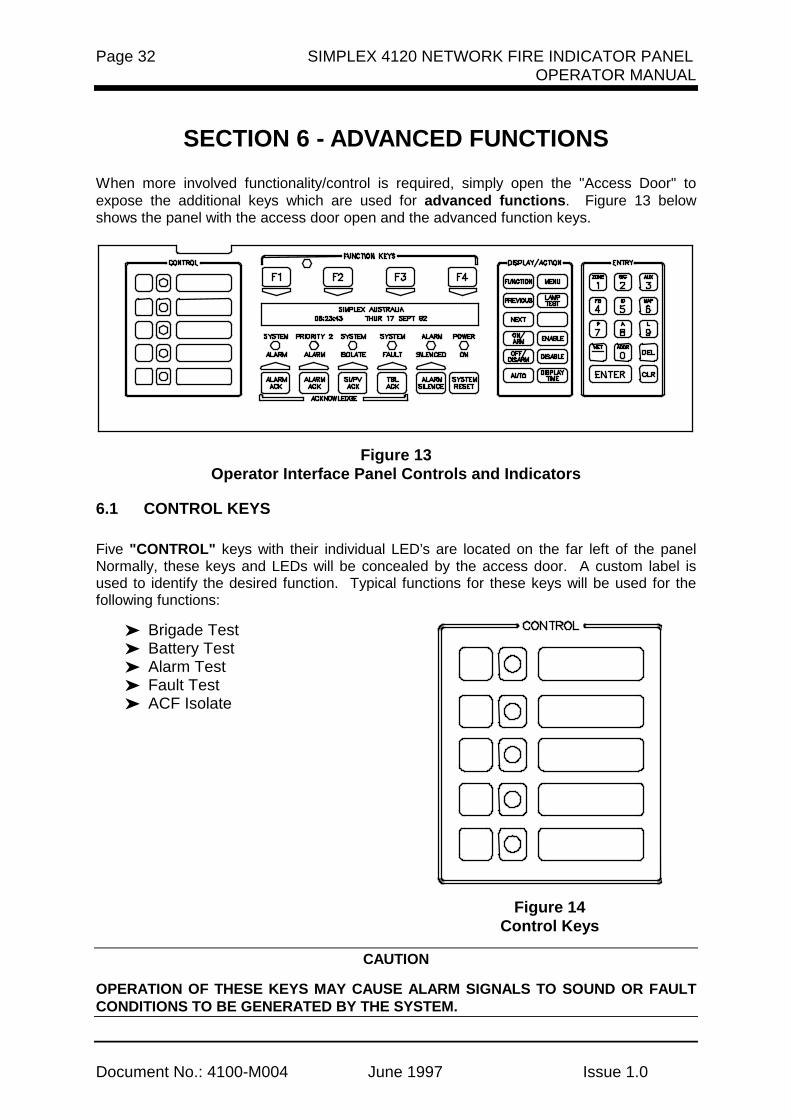
SECTION 6 - ADVANCED FUNCTIONS ................................................................. 32
6.1 CONTROL KEYS................................................................................................... 326.2 FUNCTION KEYS .................................................................................................. 336.3 HOW TO SET TIME AND DATE ............................................................................ 336.4 HOW TO ESCAPE FROM MENU .......................................................................... 356.5 POINT CONTROL WITH THE FUNCTION KEY .................................................... 356.6 DISPLAY/ACTION KEYS....................................................................................... 36
6.6.1 Function Key Operation ................................................................................ 376.6.2 MENU Key.................................................................................................... 376.6.3 PREVIOUS Key............................................................................................ 386.6.4 NEXT Key..................................................................................................... 386.6.5 LAMP TEST Key .......................................................................................... 386.6.6 Action Keys .................................................................................................. 386.6.7 Entry Keypad................................................................................................ 39
6.7 HOW TO ENTER A PREFIX .................................................................................. 396.8 HOW TO DISPLAY MAPNET II® POINT STATUS ................................................. 416.9 HOW TO DISPLAY THE SENSITIVITY OF A TRUEALARM™ SENSOR ................. 436.10 ADDITIONAL KEYS............................................................................................. 45
6.10.1 Enter........................................................................................................... 456.10.2 Clear........................................................................................................... 456.10.3 Hyphen ....................................................................................................... 456.10.4 Delete ......................................................................................................... 46
6.11 POINT SELECTION ............................................................................................. 466.11.1 Selecting Points Using Lists ....................................................................... 466.11.2 Selecting Points Using the Keyboard.......................................................... 466.11.3 Selecting Additional Lists............................................................................ 46

SIMPLEX 4120 NETWORK FIRE INDICATOR PANEL Page vOPERATOR MANUAL
Document No: 4100-M004 June 1997 Issue 1.0
6.12 OPERATOR ACCESS LEVELS........................................................................... 476.13 POWER UP SEQUENCE..................................................................................... 48
SECTION 7 - SYSTEM TEST PROCEDURES ........................................................ 49
7.1 LAMP TEST ........................................................................................................... 497.1.1 Walk Test™.................................................................................................. 49
7.2 HOW TO TURN A POINT OFF .............................................................................. 497.3 HOW TO TURN A POINT ON ................................................................................ 507.4 HOW TO RETURN A POINT TO AUTO ................................................................. 517.5 WHAT TO DO IN CASE OF SYSTEM MALFUNCTION ......................................... 52
SECTION 8 - MAINTENANCE PROCEDURES....................................................... 53
8.1 WEEKLY TESTS.................................................................................................... 538.2 MONTHLY TESTS ................................................................................................. 548.3 ANNUAL TESTS .................................................................................................... 55

Page vi SIMPLEX 4120 NETWORK FIRE INDICATOR PANELOPERATOR MANUAL
Document No.: 4100-M004 June 1997 Issue 1.0
PANEL DETAILS
panel sticker
4100 Panel supplied by
Installation location
Contract/Job Number As installed FIP System drawing number
Panel Installation date
Panel Commissioned date
Maintenance Company
Telephone
Service Contact

SIMPLEX 4120 NETWORK FIRE INDICATOR PANEL Page viiOPERATOR MANUAL
Document No: 4100-M004 June 1997 Issue 1.0
COMPATIBLE ACTUATING DEVICES
The following detectors have been approved as compatible devices for use with the4100 FIP.
SIMPLEX RANGE:
1) Analog Addressable Sensors
4098-9701 High / Very High sensitivity Photoelectric smoke4098-9716 Ionisation smoke4098-9731 Type A / Type B Heat4098-9781 Addressable LED Indicating base4098-9782 Addressable LED Indicating base with Sounder4098-9783 Addressable LED Indicating base with Relay driver
2) Conventional Detectors
4098-9413 Heat detector Type A4098-9414 Heat detector Type B4098-9415 Heat detector Type C4098-9416 Heat detector Type D2098-9201 Photoelectric smoke detector2098-9576 Ionisation smoke detector2098-9211 Universal base.
HOCHIKI RANGE: Conventional Detectors
DCA-B-60R MK V Type A heat detectorDFE-60B Type B heat detectorDCA-B-90R MK 1 Type C heat detectorDFE-90D Type D heat detectorDFG-60BLKJ Type B heat detectorSPA-AB Beam type smoke detectorSIH-AM Ionisation smoke detectorSLK-A Photoelectric smoke detectorSLG-AM MK 1 Photoelectric smoke detectorHF-24A MK 1 Ultraviolet smoke detectorYBC-R/3A Plain - non indicating baseYBF-RL/4AH4 LED Indicating base
Page viii SIMPLEX 4120 NETWORK FIRE INDICATOR PANELOPERATOR MANUAL
Document No.: 4100-M004 June 1997 Issue 1.0
OLSEN RANGE: Conventional Detectors
B111B Beam type smoke detectorC24B Ionisation smoke detectorC29B Ionisation smoke detectorFW81B Heat detector cableP24B Photoelectric smoke detectorP29B Photoelectric smoke detectorR24B Dual spectrum infrared flame detectorT54B Probe type heat detector type ET56B Heat detector types A,B,C,D with Z55B baseT56B Heat detector types A,B,C,D with Z54B baseV41B/V42B Ultraviolet flame detector
APOLLO: Conventional Detectors
Heat detector Type AHeat detector Type BHeat detector Type CHeat detector Type DSeries 20 Photoelectric smoke detectorSeries 30 Ionisation smoke detector
PANELECT/PANASONIC: Conventional Detectors
PFS-A Heat detector Type APFS-B Heat detector Type BPFS-C Heat detector Type CPFS-D Heat detector Type DPFS-P Photoelectric smoke detectorPFS-I Ionisation smoke detector

SIMPLEX 4120 NETWORK FIRE INDICATOR PANEL Page ixOPERATOR MANUAL
Document No: 4100-M004 June 1997 Issue 1.0
COMPATIBLE BATTERIES
The following series of batteries are compatible with the 4100 FIP:
(1) Power-Sonic PS12 series
(2) Sonnenschien A200 series
(3) Sonnenschien A300 series
(4) Yuasa NP series

Page x SIMPLEX 4120 NETWORK FIRE INDICATOR PANELOPERATOR MANUAL
Document No.: 4100-M004 June 1997 Issue 1.0
SPECIFICATION
GENERAL
System Capacity 1,000 points of addressable input / output devices or conventional zones.
Cabinet Size(mm) Dependent on system configurationCabinet Material 1.5mm Mild grade steelCabinet Finish Powder coatedCabinet Colour Magnolia RippleMounting Wall mount
Mains Input 240V AC, +6%,-10%, 50HzInternal Power Supply 24V DC @ 6.5AStandby Battery 24V sealed lead acid up 110AhBattery Charger 27.6V DC (nominal) @ 3.5A,PSU Supervision Charger high/low, Battery low/failTemperature -5 C to 45 CHumidity 10% to 90% RH non-condensing.
EXPANSION MODULES
Maximum Number 119 modules
4100 - 5002 Conventional zone moduleEight zone circuits per moduleSupports standard 20V detectors plus normally opencontact devices
4100 - 3003 Eight CPU controlled auxiliary relays per moduleSPDT contacts rated for 3 amps @ 24VDC or 30VAC
4100 - 0113 RS-232 / 2120 Communications ModuleProvides two RS-232-C outputs for remote printersand/or CRTFive RS-232-C ports maximum per 4100 systemCan be configured for communication with a host 2120systemCan be configured as a Computer Port forcommunications to a remote system i.e. BMS or BASSystems

SIMPLEX 4120 NETWORK FIRE INDICATOR PANEL Page xiOPERATOR MANUAL
Document No: 4100-M004 June 1997 Issue 1.0
EXPANSION MODULES - Continued
4100-6011 4120 Network Interface ModuleRS485 CommunicationsOptional Fiber Optics Media Card
4100 - 0110 MAPNET® TRUEALARM™ Addressable Loop ModuleUp to 127 MAPNET Addressable devices or TrueAlarmAnalog SensorsUp to 10 MAPNET Loop Cards per 4100 systemSupports MAPNET Short Circuit Line Isolator Modules
4100 - 0304 Remote Unit Interface ModuleProvides a supervised serial communications channel toremotely located distributed Miniplex® Transpondersand LCD AnnunciatorsUp to 32 distributed Miniplex® Transponders and/or LCDAnnunciators per 4100 system
4100 - 3024 24 Relay Input / Output Relay Motherboard24 CPU controlled relaysEach of the 24 relays can be individually configured aseither an input or an outputSPST contacts rated for 0.5 amps @ 24VDC or 30VAC
4100 - 0301 64/64 LED / SWITCH ControllerInterfaces up to 64 LEDs and 64 switches to the mastercontroller for front panel annunciation
INDICATORS and DISPLAY
Zone Status 2 line by 80 character backlight Liquid Crystal Display with adjustable contrast control
LED Status Indicators Common Alarm, Fault and IsolateBell Isolated, ACF Isolated, Mains Power ON
Audible Buzzer Alarm And Fault IndicationsKeypress feedback
KEYPAD CONTROLS
Operator Keypad ACKNOWLEDGE, SYSTEM RESET, ISOLATE,
Service Technician 20 keys including:- Alarm Test, Fault Test,Keypad Isolate, Battery Test and Lamp test

Page xii SIMPLEX 4120 NETWORK FIRE INDICATOR PANELOPERATOR MANUAL
Document No.: 4100-M004 June 1997 Issue 1.0
SOFTWARE FEATURES
* WALK TEST System Test* 4 Operator Access Levels* 600 Event Historical Logging* Zone selectable Alarm Verification* Individual Circuit Disconnect / Isolate* Nonvolatile Flash EPROM for field editable program changes

SIMPLEX 4120 NETWORK FIRE INDICATOR PANEL Page xiiiOPERATOR MANUAL
Document No: 4100-M004 June 1997 Issue 1.0
. . INDICATOR.
- PRE SS "A LARM SILENCE".
ACK
FIRE S YSTEM SIGNALS POWER ON
RE SET ACK
. . INDICATOR.
- PRE SS "A LARM SILENCE".
ACK
FIRE S YSTEM SIGNALS POWER ON
RE SET ACK
. . INDICATOR.
- PRE SS "A LARM SILENCE".
ACK
FIRE S YSTEM SIGNALS POWER ON
RE SET ACK
. . INDICATOR.
- PRE SS "A LARM SILENCE". ACK
FIRE S YSTEM SIGNALS POWER ON
RE SET ACK
. . INDICATOR.
- PRE SS "A LARM SILENCE". ACK
FIRE S YSTEM SIGNALS POWER ON
RE SET ACK
Token
Figure 14120 Fire Alarm Network


SIMPLEX 4120 NETWORK FIRE INDICATOR PANEL Page 1OPERATOR MANUAL
Document No: 4100-M004 June 1997 Issue 1.0
SECTION 1 - SYSTEM OVERVIEW
1.1 INTRODUCTION TO NETWORKING
The Simplex 4120 Network is a system of individual Fire Alarm Control Panelscommunicating on a loop as a Peer-to-Peer network (refer Figure 1). This means that everynetwork panel has an equal chance of putting a message out on the network. Each panelwith direct communications into the 4120 Network is defined as a “Node”. Each node canmaintain the status and control of its own dedicated circuit points while monitoring andcontrolling activity at other locations.
The communications scheme used by the network is based on Token Ring CommunicationsProtocol. In Token Ring communications, an electronic data “flag” or “token” is passed fromone node to the next. The node that holds the token is the only one permitted to talk on thenetwork. A node that has no messages or requests for the network simply passes the tokenonto the next node. Thus, every node has an equal chance of putting a message out on thenetwork when needed.
A 4120 Network Node can be any of the following:
• 4120 Fire Alarm Control Panel• 4120 Voice Fire Alarm Control Panel• 4120-8010 Miniplex Control Panel• 4120-8511 Universal Transponder (UT)• 4120 Status Command Centre• 4120-8821 2500 NDU with Command Centre
An existing 4100 Fire Alarm Control Panel or Universal Transponder can also be included inthe network by installing a 4120-0140 RS-485 Network Interface Card into a panel slot in theexisting unit and configuring the panel to accept the card. Network information in sequentially transmitted from one node to another. At each node,the network message is captured and either retransmitted as received, or modified beforeretransmission to provide the network with a status update. The ability of the message tocirculate through the network defines network status and allows the nodes to respondaccordingly.
If a node goes off-line, its network interface module will bypass that connection until thenode is back on-line. If the wires between nodes short, open or have any other form ofcommunication problem, the network will isolate that section of wiring. A node that cannotretransmit a message to the next node will transmit back to the previous node to maintaincommunications and to notify the network of the node status.
In the event of multiple wiring problems, the remaining nodes will effectively “regroup” andestablish new, smaller “sub-networks” that will maintain communications among the activenodes.

Page 2 SIMPLEX 4120 NETWORK FIRE INDICATOR PANELOPERATOR MANUAL
Document No.: 4100-M004 June 1997 Issue 1.0
1.2 SYSTEM INTRODUCTION
A 4120 Fire Alarm Network System may comprise of the following Network Fire Alarmpanels, depending upon total network point capacity:
• 4120 Fire Alarm Panel for system with up to 1,000 network points
• 4120 Network Display Unit (NDU) with Status Command Centre, for systems with up to2,500 network points.
1.2.1 4120 Fire Indication Panel
The Simplex 4120 is a microprocessor based Fire Alarm Control Panel which uses the latestin life safety technology and is certified to Australian Standard AS1603.4. The 4120 FireIndicator Panel has the capacity to monitor and control up 1,000 devices . These devicescan either be conventional zones of detectors or analogue addressable devices. In theevent of AC mains loss, standby batteries provide a backup 24VDC supply.
The 4120 FIP uses a micro-controller with a Flash EPROM, allowing the use of laptopcomputer to download custom program changes directly into the 4120 for easier on-site jobchanges . Battery-backed RAM has been added to maintain important historical data, evenduring a complete power-down of the system.
The 4120 also uses a switching power supply to provide up to 7 Amps of power at 24 VDCfor load devices and system operation, plus up to 3 Amps for battery chargingresponsibilities. In addition, this power supply can communicate directly with the MasterController via internal serial communications, reporting such data as system voltage andcurrent usage and battery charging information.
The 4120 FIP has been designed to be a custom, factory configured system and whendelivered to the job site, becomes a totally field editable and configurable system inresponse to unforeseen job changes.
To provide maximum efficiency in performing primary fire alarm functions, the 4120Operator Interface Panel makes visible only the indication and interaction keys required inan emergency situation .
Alarm, Isolation and Fault conditions are indicated at the operator’s panel by dedicatedLEDs and a Piezo sounder. Each of these system conditions has a dedicated acknowledgebutton.
A 2 line, 80 character alphanumeric LCD display is used to annunciate a 40 charactercustom label message per device or circuit, the device point type (smoke detector, manualcall point, etc.), the current status of the device or circuit (alarm, fault etc.) as well asoperator prompts for acknowledging status changes or inputting commands.
The alphanumeric display will show various prompts and labels which are used to guide theuser through a sequenced operation for each abnormal condition.

SIMPLEX 4120 NETWORK FIRE INDICATOR PANEL Page 3OPERATOR MANUAL
Document No: 4100-M004 June 1997 Issue 1.0
The 4120 can be programmed to perform a "global acknowledge" where a single key pressof the appropriate acknowledge button will silence the piezo for all points in that condition.The 4120 can also be programmed for individual acknowledgment of each point in anabnormal condition as well as its restoration.
After an alarm condition, the system can be restored to normal operating mode bydepressing the " System Reset" button. To serve as a "fault reminder" when a fault conditionremains in the system and audible fault signal has been silenced, the piezo will resound at aspecified time interval to alert the user that the fault condition remains and needsrectification.
The operator’s interface door provides easy access to additional operator controls and LEDindicators. The depth of the operator’s interaction is determined by four Security Accesslevels.
Level 1 is the lowest level and allows the operator to perform routine actions. Level 4 on theother hand is the highest level and only provides for the most sensitive operations by anauthorised service technician. Each of these access levels is governed by a passcodechosen at order entry or as edited by a Simplex service technician.
The "FUNCTION KEYS", "DISPLAY/ACTION" keypad, and the "ENTRY" keypad are theoperator interface sections which provide, in a self -directing manner, operations non-essential in a fire emergency situation.
These operations include items such "ISOLATE" or "DE-ISOLATE" a circuit, turn a controlpoint "ON" or "OFF", and menu items such as "SET TIME AND DATE", "DISPLAYHISTORICAL LOGS", etc. Programmable "CONTROL" keys and their associated LEDs canbe programmed to perform a variety of functions and can be individually passcodeprotected. These "CONTROL" keys are typically used for alarm and fault test, ACF Isolate,Brigade test and battery test functions.
1.2.2 2500 Network Display Unit
The Simplex 2500 Network Display Unit (NDU) is a network annunciator and manualsystem/point controller for a 4120 Network. The NDU provides alphanumeric annunciationfor up to 2,500 network points and/or point lists and can be programmed to function as thenetwork master controller for Silence, Acknowledge and System Reset.
Standard features include an alphanumeric display exactly like the 4100 Fire Alarm ControlPanel and more memory to achieve 2,500 point capacity.
The increased memory size provides 600 alarm and 600 fault event history logs, twice thesize of any other 4120 or 4100 model. The 2500 NDU can drive up to 31 serial LCDAnnunciators on one optional Remote Unit interface (RUI) card. In addition, the NDU canhave up to five RS-232 ports for printers and CRT/Keyboards.

Page 4 SIMPLEX 4120 NETWORK FIRE INDICATOR PANELOPERATOR MANUAL
Document No.: 4100-M004 June 1997 Issue 1.0
1.2.3 2500 NDU with Status Command Centre
The 2500 NDU with Status Command Centre combines the 2500 NDU with a customselection of modular LED and/or LED and control switch assemblies that provide adedicated monitor and control interface. Voice modules are available with this model toconfigure this panel into a Voice Command Centre.
The NDU with Status command Centre is actually two nodes in one cabinet assembly. TheNDU occupies the top bay of the unit and the Command Centre occupies the rest.
1.3 SYSTEM OPERATING DESCRIPTION
NOTE: This document covers the operating procedures for a typical 4120 FIP Applicationswill vary due to custom programming and local code requirements.
An alphanumeric display on the 4120 FIP Operator Interface Panel (Figure 2) indicates thecondition of the system. The alphanumeric display shows the various labels and promptswhich guide the user through a sequenced operation for each abnormal condition.
Figure 24100 Operator Interface Panel(Panel Access Door Closed)
Audible and visual indication are provided to indicate abnormal conditions, when they existthroughout the network.
The 4120 FIP Operator Interface Panel, hereinafter called the interface panel, shows thefollowing under normal conditions:
• Green "POWER ON" LED ON (indicating that AC power is applied).• All other interface panel indications OFF.• Alphanumeric display states that the SYSTEM IS NORMAL followed by the time and
date as shown below.

SIMPLEX 4120 NETWORK FIRE INDICATOR PANEL Page 5OPERATOR MANUAL
Document No: 4100-M004 June 1997 Issue 1.0
SIMPLEX AUSTRALIA SYSTEM IS NORMAL 08:23:43 MON 25 JAN 95
Abnormal conditions are indicated on the interface panel by flashing the alarm, isolate, orfault LED and sounding the tone-alert. The alphanumeric display provides information as tothe point status (alarm, isolated, and fault), type of alarm (smoke detector, pull station, etc.),number of abnormal conditions in the system, and a custom label. Alarm, isolate and faultconditions each have their respective acknowledge key. Pressing the appropriateacknowledge key will silence the tone-alert. However, the LED indicating the abnormalcondition remains illuminated until all initiating devices are restored to normal.
If your system is configured with a CRT or printer option, point status is also displayed onthese devices. The CRT option controls various system functions. It can also acknowledgesystem status changes, silence alarm signals, and perform system reset procedures.
When a monitor zone or device senses an Alarm condition (heat, smoke, manual call point),this is relayed to the 4120 FIP and displayed on the Interface Panel by the SYSTEMALARM LED flashing, tone-alert sounding, and zone alarm LED turning on. In addition,depending on the nature of the alarm condition, the fire trip relays will be activated, brigadecall relay will turn ON and various programmed events will occur.
When the 4120 FIP senses a malfunction within the system (loss of power, hardware failure,zone fault, etc.) a FAULT condition is annunciated. The tone-alert turns on steady, theFAULT LED will flash .
All abnormal conditions must be acknowledged by pressing the <ACK> key under theappropriate flashing LED.
The system has "re-sound" capability. If, after silencing the tone-alert, the system detectsanother abnormal condition, the zone with the abnormal condition will be indicated on thepanel’s alphanumeric display, the appropriate indicator will again flash and the tone-alert willsound.
To provide maximum efficiency in performing primary fire alarm functions, the front panelaccess door covers all keys except those required for indication and interaction foremergency situations.
1.3.1 Operator Log In/Log Out Procedures
Various functions may be passcode protected to prevent access by unauthorised personnel.Passcodes are provided to the user during system installation. To change or receiveadditional information concerning your passcodes, contact your local Simplex Branch Office.
Page 6 SIMPLEX 4120 NETWORK FIRE INDICATOR PANELOPERATOR MANUAL
Document No.: 4100-M004 June 1997 Issue 1.0
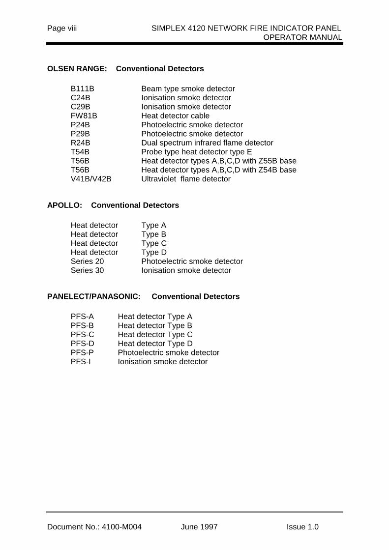
1.3.1.1 Access Level Log-In Procedure
To Log on, perform the following procedure.
1. Obtain the appropriate passcode information.
2. Open the interface panel access door.
3. Press the <MENU> key on the DISPLAY/ACTION keypad on the right side of theinterface panel. The following is displayed.
Press <NEXT> or <PREVIOUS> to scrollChange Access Level?
4. Press the <ENTER> key on the DISPLAY/ACTION keypad the following is displayed.
F1=Login F2=LogoutCURRENT ACCESS LEVEL = 1
5. Press the <F1> key (above the alphanumeric display). The display shows thefollowing.
Enter a Passcode followed by <ENTER>
6. Enter the passcode. Press the <ENTER> key on the Entry keypad. For securityreasons, an "X" is displayed for each digit of your passcode, as shown below.
Enter a Passcode followed by <ENTER>XXX
If the passcode is correct, the following is shown.
Enter a Passcode followed by <ENTER>ACCESS GRANTED

SIMPLEX 4120 NETWORK FIRE INDICATOR PANEL Page 7OPERATOR MANUAL
Document No: 4100-M004 June 1997 Issue 1.0
After a brief pause, the display shows the granted access level, such as level 3 accessmessage shown below.
F1=Login F2=LogoutCURRENT ACCESS LEVEL = 3
7. Press <CLR> key on the ENTRY keypad twice. The display shows system status, asshown below.
SIMPLEX AUSTRALIA SYSTEM IS NORMAL 08:23:43 MON 25 JAN 95
1.3.1.2 Access Level Log Out Procedure
IMPORTANT
FAILURE TO LOG OUT ALLOWS UNAUTHORISED PERSONNEL ACCESS TO THEVARIOUS PASSCODE PROTECTED FUNCTIONS. IF NO KEYPAD ACTIVITY ISDETECTED FOR TEN MINUTES, THE SYSTEM WILL RETURN TO LEVEL 1 ACCESS.
To Log out, perform the following procedure.
1. Press the <MENU>key on the DISPLAY/ACTION keypad.
2. Press the <NEXT> key until the menu prompt "CHANGE ACCESS LEVEL?" appearson the alphanumeric display.
3. Press <ENTER> on the ENTRY keypad.
4. Press the <F2> key (above the alphanumeric display) to Log Out.
5. Press the <CLR> key on the ENTRY keypad to escape from the Main Menu.
1.3.2 HANDLING ABNORMAL CONDITIONS
If an abnormal condition occurs, at least one of the LEDs (alarm, isolate or fault) will startflashing, and the tone-alert will sound. The panel will display the total number of abnormalconditions present in the system. At a glance, the user knows how serious the situationmight be by reading the number of abnormal conditions displayed, such as the single alarmshown below.
***ALARM*** Press ACK to review.ALARMS = 1 ISOLATED = 0 FAULT = 0

Page 8 SIMPLEX 4120 NETWORK FIRE INDICATOR PANELOPERATOR MANUAL
Document No.: 4100-M004 June 1997 Issue 1.0
The 4120 FIP also creates a "List" when abnormal conditions exist. The list contains thenumber of abnormal conditions present in the system. The user pushes the <ACK> keys toview the abnormal condition list, reviews each condition, silences the alarms, views thealarm list, restores affected devices, and resets the panel, if required.
When an abnormal condition has been detected by the system, the appropriate LED will beflashing and the tone-alert will be beeping for alarm conditions. The tone-alert will be onsteady for isolate and fault conditions.
Pressing the appropriate <ACK> key (under flashing LED) will display the firstacknowledged condition in the appropriate list. The <ACK> function may be passcodeprotected. If the user has insufficient privilege to acknowledge the condition, a message willindicate the problem, but allow the user to view the points without acknowledging them. Ifthe user has sufficient privilege to acknowledge the condition, a message is displayedinforming the user that the condition has been acknowledged. (See sections on OperatorAccess Levels and Log On Procedures).
The system is configured with Global Change Acknowledge such that one press of an<ACK> key will globally acknowledge every abnormal point in the system. If all the pointswere acknowledged in this manner, an appropriate message is then displayed . When thefault condition clears, the abnormal condition will automatically clear. Alarm conditions mustbe acknowledged.
The acknowledge function imposes a delay of at least one second between pointacknowledgments. This minimum delay is to prevent the user from pressing the<ACK> key without viewing the information displayed on the alphanumeric display.
After all points have been acknowledged, the LEDs will be on steady and the tone-alert willbe silenced. The total number of alarm, isolate, and fault conditions will be shown on thealphanumeric display along with a prompt to press the <ACK> key for point review.Subsequent pressing of an <ACK> key will scroll through the selected list in chronologicalorder.
After 30 seconds of keypad inactivity, the total number of abnormal conditions will again beshown on the alphanumeric display. Pressing the <ACK> key will select a list for review.The first point to be displayed will either be the first acknowledged point in the list, or the firstpoint in the list if all are acknowledged.
Alarm, isolated and fault lists are displayed in chronological order. A message will indicatewhen the end of a list has been reached. The list message will contain the total number ofabnormal conditions, such as the single alarm shown below.
***ALARM*** Press ACK to review.ALARMS = 1 ISOLATED = 0 FAULT = 0
SIMPLEX 4120 NETWORK FIRE INDICATOR PANEL Page 9OPERATOR MANUAL
Document No: 4100-M004 June 1997 Issue 1.0
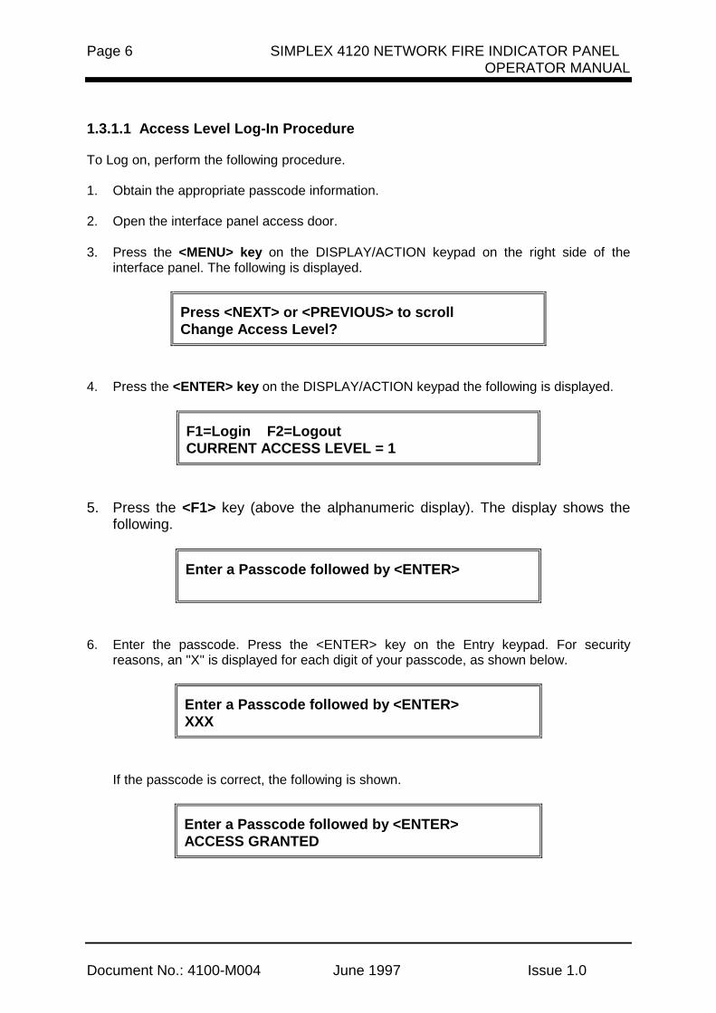
1.3.2.1 The <DISPLAY TIME> Key
The <DISPLAY TIME> key is used to view the time of day when the abnormal conditionoccurred. By viewing the time for each abnormal condition occurrence, fire brigadepersonnel can determine the path and possible cause for each abnormal condition.
Note that the <DISPLAY TIME> key only displays time for existing abnormal conditions.
The red <DISPLAY TIME> key works for any point currently in an alarm, isolate or faultcondition. The time/date information is obtained from the historical log and is shown on thealphanumeric display. In situations where multiple conditions are present, you can simplypush one key to review the time that each abnormal condition occurred. An example of analarm condition is shown below.
TOWER BUILDING 3RD FLOORSMOKE DETECTOR ALARM
If the <DISPLAY TIME> key is pressed and held down, the display shows the alarminformation, as shown below. This information is only displayed while the <DISPLAY TIME>key is held down.
TOWER BUILDING 3RD FLOORALARM AT 19:56:32 MON 25 JAN 95
When the <DISPLAY TIME> key is released, the display will revert back to its original labeland status.
To display alarm information, perform the following steps.
1. Ensure that the point to be checked is shown on the alphanumeric display by pressingthe appropriate <ACK> key.
2. Press and hold in the <DISPLAY TIME> key. Information concerning the abnormal
condition (alarm, isolate or fault) is displayed. 3. Press the appropriate <ACK> key to display the next condition change. 4. Repeat steps 2 and 3 above, as required.
NOTE: This key will not work for points directly entered into the system via the keypad (e.g.zone numbers, etc.)
Page 10 SIMPLEX 4120 NETWORK FIRE INDICATOR PANELOPERATOR MANUAL
Document No.: 4100-M004 June 1997 Issue 1.0
SECTION 2 - ALARM CONDITIONS
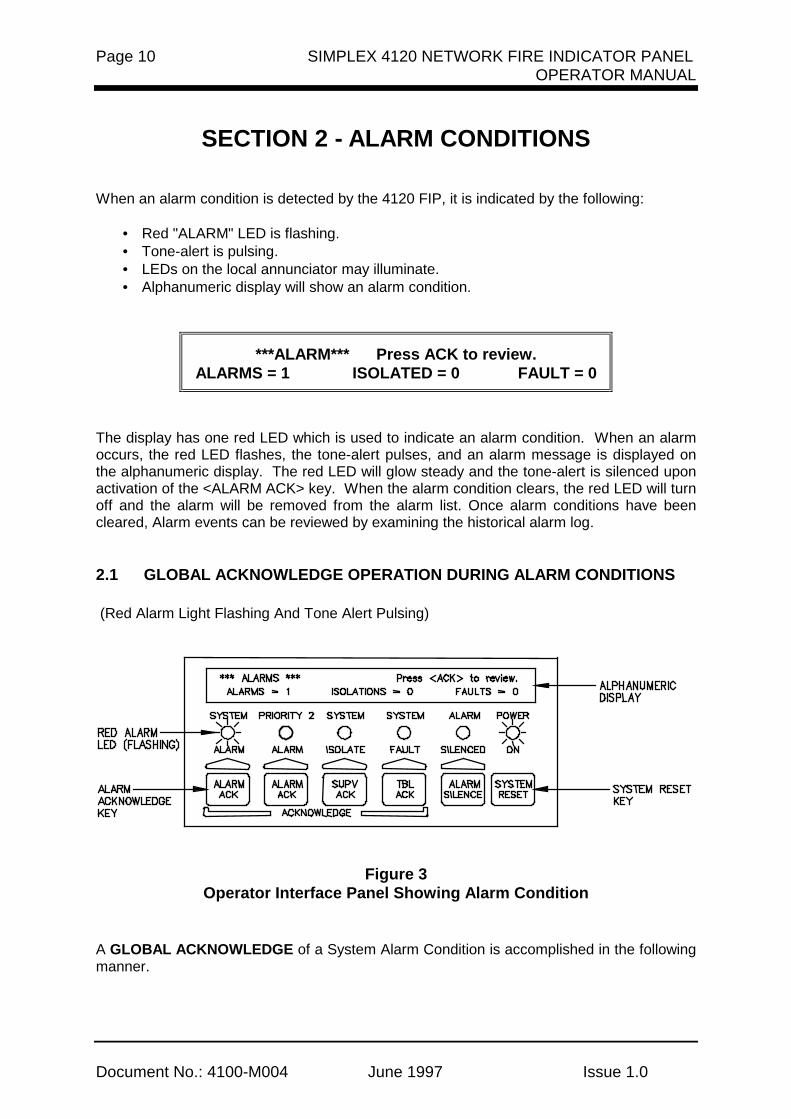
When an alarm condition is detected by the 4120 FIP, it is indicated by the following:
• Red "ALARM" LED is flashing.• Tone-alert is pulsing.• LEDs on the local annunciator may illuminate.• Alphanumeric display will show an alarm condition.
***ALARM*** Press ACK to review.ALARMS = 1 ISOLATED = 0 FAULT = 0
The display has one red LED which is used to indicate an alarm condition. When an alarmoccurs, the red LED flashes, the tone-alert pulses, and an alarm message is displayed onthe alphanumeric display. The red LED will glow steady and the tone-alert is silenced uponactivation of the <ALARM ACK> key. When the alarm condition clears, the red LED will turnoff and the alarm will be removed from the alarm list. Once alarm conditions have beencleared, Alarm events can be reviewed by examining the historical alarm log.
2.1 GLOBAL ACKNOWLEDGE OPERATION DURING ALARM CONDITIONS
(Red Alarm Light Flashing And Tone Alert Pulsing)
Figure 3Operator Interface Panel Showing Alarm Condition
A GLOBAL ACKNOWLEDGE of a System Alarm Condition is accomplished in the followingmanner.

SIMPLEX 4120 NETWORK FIRE INDICATOR PANEL Page 11OPERATOR MANUAL
Document No: 4100-M004 June 1997 Issue 1.0
1. Unlock and open the panel door. The Fire Alarm Bell will now stop sounding due tothe panel door being opened. Read the alphanumeric display. It shows the number ofalarm conditions.
***ALARM*** Press <ACK> to review.ALARMS = 1 ISOLATED = 0 FAULT = 0
2. Press the <ALARM ACK> key. Read the alphanumeric display. The tone-alert issilenced and the display will show pertinent report information, such as shown below.
1ST FLOOR EAST WING ROOM 2 AZF1SMOKE DETECTOR ALARM
The SYSTEM ALARM LED changes from flashing to steady ON, and all alarmconditions are acknowledged.
Pressing the <ALARM ACK> key scrolls through all the alarms in chronological order.
HOW TO SILENCE THE ALARM SIGNALS
Press the <ALARM SILENCE> key and read the display. The alphanumeric display willshow signal status.
ALARM SILENCE IN PROGRESS . . .
HOW TO RESET THE SYSTEM
When the alarm condition has been cleared, restore or replace all affected devices(MCP’s, smoke detectors, etc.) in accordance with the instructions provided witheach device.
Press the <SYSTEM RESET> key. After a delay, the system will return to normaland the display should show the following:
SIMPLEX AUSTRALIA SYSTEM IS NORMAL8:23:43 MON 25 JAN 95

Page 12 SIMPLEX 4120 NETWORK FIRE INDICATOR PANELOPERATOR MANUAL
Document No.: 4100-M004 June 1997 Issue 1.0
2.2 INDIVIDUAL ACKNOWLEDGE DURING ALARM CONDITIONS
An INDIVIDUAL ACKNOWLEDGE of a System Alarm Condition is accomplished inthe following manner.
1. Unlock and open the panel door. The Fire Alarm Bell will now stop sounding due tothe panel door being opened. Read the alphanumeric display. It shows the number ofalarm conditions.
***ALARM*** Press <ACK> to review.ALARMS = 1 ISOLATED = 0 FAULT = 0
2. Press the <ALARM ACK> key. Read and follow the instructions on the alphanumericdisplay. Pertinent report information is given as shown below.
1ST FLOOR EAST WING ROOM 2Press ACK key to acknowledge ALARM
SMOKE DETECTOR ALARM
Press the <ALARM ACK> key again. Read the report data. Repeat this procedure toreview all reports which are displayed in chronological order. The SYSTEM ALARMLED changes from flashing to steady ON, and all alarm conditions are acknowledged.
HOW TO SILENCE THE ALARM SIGNALS
Press the <ALARM SILENCE> key and read the display. The alphanumeric display willshow signal status.
ALARM SILENCE IN PROGRESS . . .
HOW TO RESET THE SYSTEM
When the alarm condition has been cleared, restore or replace all affected devices (MCP’s,smoke detectors, etc.) in accordance with the instructions provided with each device.
1. Press the <SYSTEM RESET> key. After a delay, the SYSTEM ALARM LED will beginto flash and the tone-alert will begin its pulsing sound.
2. Press the <ALARM ACK> key twice. After a delay, system will return to normal and the
display should show the following:
SIMPLEX AUSTRALIA SYSTEM IS NORMAL8:23:43 MON 25 JAN 95
ALTERNATINGLINES

SIMPLEX 4120 NETWORK FIRE INDICATOR PANEL Page 13OPERATOR MANUAL
Document No: 4100-M004 June 1997 Issue 1.0
2.3 ESSENTIAL ALARM CONDITION KEYS
The essential keys for alarm conditions are the <ALARM ACK>, <ALARM SILENCE> andthe <SYSTEM RESET> keys. The remaining keys are concealed by the access door andare associated with advanced functions of the system. (See Advanced Functions Section6.)
2.3.1 Alarm Ack (Acknowledge)
The <ALARM ACK> key is located directly under the SYSTEM ALARM LED. Pressing the<ALARM ACK> key (twice for Individual Acknowledge or once for Global Acknowledge) willcause the LED to change from flashing to a steady ON condition and silence the tone-alert.
Pressing the <ALARM ACK> key will:
• Select the next unacknowledged alarm point in the list for display (IndividualAcknowledge).
• Acknowledge the displayed point or acknowledge all points on the list (GlobalAcknowledge).
• Scroll the points chronologically after all points have been acknowledged.
2.3.2 System Reset
The <SYSTEM RESET> key is used to return the system to its normal state after an alarmcondition has been cleared. When the <SYSTEM RESET> key is pushed, it will cause thelatched circuits to clear automatically. All circuits include initiating devices, relays, indicatingappliances, and all LEDs and indicators which are programmed to reset with the reset key.The message, "SYSTEM RESET IN PROGRESS", will be displayed when the <SYSTEMRESET> key is pressed.
With the Individual Acknowledge systems, when the alarm condition has reset, the SYSTEMALARM LED flashes and the system requires that the <ALARM ACK> key be pressed. Themessage "SYSTEM IS NORMAL" followed by time and date should be displayed. Thisprocess will take about 45 seconds.
If a zone stays in alarm during the reset period, the message, "SYSTEM RESET INPROGRESS", will be followed by the message:
ALARM PRESENT, SYSTEM RESET ABORTED
When "SYSTEM RESET ABORTED" is displayed, the system will remain in an alarm state.The display will indicate the total number of alarms present in the system along with aprompt to use the <ALARM ACK> key to review the points. These points do not requireacknowledgment. The tone-alert and the alarm LED will be on.
Page 14 SIMPLEX 4120 NETWORK FIRE INDICATOR PANELOPERATOR MANUAL
Document No.: 4100-M004 June 1997 Issue 1.0
If the system does not reset, no fire exists, and the display still shows an alarm, read thealphanumeric display to determine the type of device and the zone number in alarm. Followlocal procedures to investigate the area of the building with the alarm. Look for devices stillin alarm (manual call points, smoke detectors, etc.). Most devices latch until they are reset,either by the system or manually.
2.4 HOW TO ISOLATE / DE-ISOLATE A ZONE
If a device will not reset, the user may elect to perform the ISOLATE procedures listedbelow.
IMPORTANT
IT IS IMPORTANT TO REMEMBER THAT ONCE A POINT IS ISOLATED, IT WILL NOTPROVIDE FIRE PROTECTION. REPAIR/REPLACE THE DEVICE AS SOON ASPOSSIBLE. ONCE REPAIRED, THE POINT SHOULD BE ENABLED AS SOON ASPOSSIBLE.
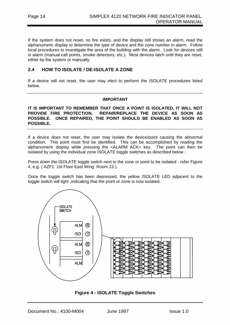
If a device does not reset, the user may isolate the device/point causing the abnormalcondition. This point must first be identified. This can be accomplished by reading thealphanumeric display while pressing the <ALARM ACK> key. The point can then beisolated by using the individual zone ISOLATE toggle switches as described below :
Press down the ISOLATE toggle switch next to the zone or point to be isolated - refer Figure4, e.g. ( AZF1 1st Floor East Wing Room 23 ).
Once the toggle switch has been depressed, the yellow ISOLATE LED adjacent to thetoggle switch will light ,indicating that the point or zone is now isolated.
Figure 4 - ISOLATE Toggle Switches

SIMPLEX 4120 NETWORK FIRE INDICATOR PANEL Page 15OPERATOR MANUAL
Document No: 4100-M004 June 1997 Issue 1.0
The display will indicate a ISOLATED condition, until the isolated point has been de-isolated.
When a zone is isolated via the zone isolate switches , the condition is indicated on the main4100 FIP as follows:
• Yellow "SYSTEM ISOLATE" LED is flashing.• Tone-alert is on steady.• Alphanumeric display shows the following:
**ISOLATIONS** Press ACK to review. ALARMS = 0 ISOLATED = 1 FAULT = 0
1. The panel has a yellow isolate LED which will light whenever an isolation is present inthe system. When a zone is isolated, the LED will flash, the tone-alert sounds steady,and a fault message will be displayed on the alphanumeric display. The isolate LED willglow steady and the tone-alert silences when the <ISOLATE ACK> key is pressed.
2. To de-isolate the point or zone, either depress or lift the toggle switch (refer Figure 4) ,
the yellow LED will turn off and the point or zone will be de-isolated. 3. Once all faults have been removed from the system, the display will read SYSTEM
NORMAL. 4. Repeat steps 1 and 2 to isolate the required zones.
Note: Any time a zone is isolated, the event is recorded in the fault log.
If an Alarm condition occurs on an isolated zone, the Alarm will still be annunciated on theoperator panel, however the brigade relay will not activate nor will any programmedsequence occur.

Page 16 SIMPLEX 4120 NETWORK FIRE INDICATOR PANELOPERATOR MANUAL
Document No.: 4100-M004 June 1997 Issue 1.0
2.5 HOW TO ISOLATE / DE-ISOLATE INDIVIDUAL DEVICES
As an alternative to isolating a zone of devices, the user may isolate individual devices in azone.
2.5.1 Disabling Individual Points/Devices
If a device does not reset, you may disconnect the device/point causing the alarm condition.However this point must first be identified as follows:
1. Press the <ALARM ACK> key and read the alphanumeric display on the interfacepanel.
2. Open the Operator Panel "Access Door" to expose the additional keys which are
available for advanced functions. Then disable the identified alarm point with the<DISABLE> key. If the <DISABLE> key is passcode protected, perform the Log Onprocedure before performing the Isolate procedure. (Refer Section 3.1 Operator LogIN/OUT procedure).
The <DISABLE> key press removes power to any displayed monitor point. Thus disabling apoint causes a fault condition to be displayed.
To isolate a point, perform the following procedure:
1. Open the Operator Interface Panel access door. 2. Press the <ALARM ACK> key until the point to be isolated is shown on the
alphanumeric display, as shown below
M1-1 1ST FLOOR EAST WING ROOM 2 AZF1SMOKE DETECTOR ALARM
3. Press the <DISABLE> key. The display shows the following message:
Press <ENTER> to ISOLATEM1-1
4. Press the <ENTER> key. The display shows the action taken.
ACTION TAKEN
Note: The system indicates a Fault condition each time a point is isolated. Press the<FAULT ACK> key as required. To clear the alarm condition, follow the SystemReset Procedures.
5. Repeat steps 2 through 4 above to isolate additional points.

SIMPLEX 4120 NETWORK FIRE INDICATOR PANEL Page 17OPERATOR MANUAL
Document No: 4100-M004 June 1997 Issue 1.0
2.5.2 Enabling Individual Points/Devices
If a device was isolated for any reason and has been restored, you can enable the point.This point must first be identified to the system. The isolated point causes a system faultcondition which is continually shown on the display. This can be viewed by pressing theFault <ACK> key and reading the display. The point can be enabled by using the<ENABLE> KEY. IF THE <enable> KEY IS PASSCODE PROTECTED, PERFORM "Log OnProcedures" then continue.
To enable a isolated point, perform the following steps:
1. Press the <FAULT ACK> key until the point to be enabled is shown on thealphanumeric display, as shown below
M1-1 1st Floor East Wing Room 2 AZF1SMOKE DETECTOR ISOLATE FAULT
2. Press the <ENABLE> key. The display shows the following message:
Press <ENTER> to ENABLEM1-1
Note: Read the warning below before performing the following step
3. Press the <ENTER> key. The display shows the following message.
Please stand by...M1-1 will ENABLE in 60 seconds
WARNING
If the zone is still in alarm, a WARNING is displayed which tells you that the systemwill sound an alarm if the timer (60 seconds) times out. TO ABORT THE ENABLE,PRESS THE <ISOLATE> KEY. If an alarm condition exists, the following is shown onthe display.
**WARNING** Press <ISOLATE> to abortM1-1 will ALARM in 60 seconds
IF THE ABOVE WARNING IS SHOWN ON THE DISPLAY, PRESS THE <ISOLATE> ORAN <ACK> KEY. FAILURE TO ABORT THE ENABLE WILL CAUSE AN ALARMCONDITION, CALL THE FIRE BRIGADE AND PUT THE BUILDING INTO FIRE MODE.

Page 18 SIMPLEX 4120 NETWORK FIRE INDICATOR PANELOPERATOR MANUAL
Document No.: 4100-M004 June 1997 Issue 1.0
If the enable process is successful, the following message is shown on the display:
ENABLE COMPLETED
4. Repeat steps 1 through 3 above to ENABLE the required points.

SIMPLEX 4120 NETWORK FIRE INDICATOR PANEL Page 19OPERATOR MANUAL
Document No: 4100-M004 June 1997 Issue 1.0
SECTION 3 - FAULT CONDITIONS
When a fault condition is detected by the 4120 FIP, the condition is indicated on the main4120 Interface Panel as follows:
• Yellow "SYSTEM FAULT" LED is flashing.• Tone-alert is on steady.• Alphanumeric display shows the following:
**FAULT ** Press ACK to review.ALARMS = 0 ISOLATED = 0 FAULT = 1
The panel has a yellow fault LED which will light whenever a fault is present in the system.When a fault occurs, the LED will flash, the tone-alert sounds steady, and a fault messagewill be displayed on the alphanumeric display. The fault LED will glow steady and thetone-alert silences when the <FAULT ACK> key is pressed.
When Global Acknowledge is used and the fault clears, the system automatically clearswithout user intervention. After approximately 30 seconds, the system should display"SYSTEM IS NORMAL” followed by time and date.
SIMPLEX AUSTRALIA SYSTEM IS NORMAL08:23:43 FRI 11 MAR 95
When Individual Acknowledge is used, the tone-alert “re-sounds” when the fault clears. The<FAULT ACK> key must be pressed twice (once to change from Alarm Summary to actualpoint, and once to acknowledge the condition). After a delay, the alphanumeric displayshould indicate a normal system.
3.1 GLOBAL ACKNOWLEDGE OPERATION DURING FAULT CONDITIONS
(Yellow LED Is Flashing And Tone-Alert Is On Steady)
Figure 5Operator Interface Showing Fault Conditions

Page 20 SIMPLEX 4120 NETWORK FIRE INDICATOR PANELOPERATOR MANUAL
Document No.: 4100-M004 June 1997 Issue 1.0
A GLOBAL ACKNOWLEDGE of a fault condition is accomplished in the following manner.
1. Unlock and open the panel door. The alphanumeric display will show the faultcondition.
** FAULT ** Press <ACK> to review pointsALARMS = 0 ISOLATED = 0 FAULT = 1
2. Press the <FAULT ACK> key under the flashing yellow LED. The alphanumeric displaywill show area and type of fault. The tone alert will silence and the yellow LED will glowsteady.
FIRST FLOOR EAST WING AZF1FIRE MONITOR ZONE OPEN CIRCUIT FAULT
3. Read the alphanumeric display, then investigate the problem to determine its cause.
• Restore or replace the defective device in accordance with device instructions.
• The fault will automatically clear when the problem has been corrected.
• After a delay, the alphanumeric display should show:
SIMPLEX AUSTRALIA SYSTEM IS NORMAL8:23:43 MON 25 JAN 95
3.2 INDIVIDUAL ACKNOWLEDGE OPERATION DURING FAULT CONDITIONS
An INDIVIDUAL ACKNOWLEDGE of a fault condition is accomplished in the followingmanner.
1. Unlock and open the panel door. The alphanumeric display will show the faultcondition.
** FAULT ** Press <ACK> to review pointsALARMS = 0 ISOLATED = 0 FAULT = 1
2. Press the <FAULT ACK> key under the flashing yellow LED. Repeat this step and readthe reports. The alphanumeric display will show area and type of fault. The tone alertwill silence and the yellow LED will glow steady.
1ST FLOOR EAST WING ROOM 2Press ACK key to acknowledge
FIRE MONITOR ZONE OPEN CIRCUIT FAULT
ALTERNATINGLINES

SIMPLEX 4120 NETWORK FIRE INDICATOR PANEL Page 21OPERATOR MANUAL
Document No: 4100-M004 June 1997 Issue 1.0
3. Read the alphanumeric display, then investigate the problem to determine its cause.Restore or replace the defective device in accordance with device instructions.
Note: When the fault clears, the fault LED flashes and the tone-alert sounds steady. 4. Press the <FAULT ACK> key under flashing yellow LED. The alphanumeric display
shows the system status. 5. Press the <FAULT ACK> key under flashing yellow LED again. After a delay, the
alphanumeric display should show:
SIMPLEX AUSTRALIA SYSTEM IS NORMAL8:23:43 MON 25 JAN 95
3.4 ESSENTIAL FAULT CONDITION KEYS
The essential keys for fault conditions are <FAULT ACK>, and the <SYSTEM RESET>keys. The remaining keys are concealed by the access door and are associated withadvanced functions of the system. (See Advanced Functions Section 6). Use of thesekeys require advanced user skills.
3.4.1 Fault Acknowledge Key
The <FAULT ACK> key is used to scroll through the various displays on the alphanumericdisplay. It also controls the Fault LEDs and the tone-alert. The <FAULT ACK> key islocated directly under the fault LED. Pressing the <FAULT ACK> key (twice for IndividualAcknowledge or once for Global Acknowledge) will cause the LED to change from flashingto on steady and silence the tone-alert. When the <FAULT ACK> key is pressed, it will:
• Select the next unacknowledged fault point and display it on the alphanumeric display(Individual Acknowledge).
• Acknowledge the displayed point or acknowledge all points on the list (GlobalAcknowledge).
• Silence signals programmed to follow the Fault Acknowledge key.
• Scroll the points chronologically after all points have been acknowledged.
There are two types of acknowledges for the 4120 FIP: Global Acknowledge andIndividual Acknowledge. Each acknowledge type operates with the Fault Conditionin the following manner.
• When Global Acknowledge is used on the 4120 system, a single key press willacknowledge all fault changes in the system. If status change information is required,the user may review this data (after a delay) by pressing the <ACK> key and reading thetotal number of fault changes on the alphanumeric display.

Page 22 SIMPLEX 4120 NETWORK FIRE INDICATOR PANELOPERATOR MANUAL
Document No.: 4100-M004 June 1997 Issue 1.0
• When Individual Acknowledge is used and a fault condition has been acknowledgedwith the <ACK> key, and further unacknowledged fault conditions remain in the system,the tone-alert continues to sound and the next status change is shown on thealphanumeric display.
NOTE: Normally, points may not require acknowledgment and do not latch. If the systemdoes not clear, read the display, then check for devices still in fault (manual callpoints, smoke detectors etc.).
3.4.2 System Reset to Clear Faults
Some faults latch until they are reset manually or can be cleared by pressing the <SYSTEMRESET> key once the fault condition has been rectified. This applies to Open Circuit faultson MAPNET and RUI communications lines.
If a monitor point or device intermittently toggles faults or will not reset, the user may elect toISOLATE the faulty zone or isolate the faulty device. (Refer Section 2.4 for isolateprocedures).
3.5 FAULT INDICATIONS FOR TrueAlarm™ SENSORS
The devices that are used for TrueAlarm™ operation are considered sensors instead ofdetectors, because these devices do not determine alarm conditions. The TrueAlarm™smoke sensor is a measuring device that sends data regarding smoke density to the 4100control panel. The TrueAlarm™ heat sensor operates in a similar fashion, but sendstemperature data instead of smoke density data. The 4100 uses this data to determinewhether a fault has occurred. This basic operational difference is the key to TrueAlarm™operation.
The TrueAlarm™ sensor has two automatic fault conditions: ➤ Dirty, and ➤ Excessively Dirty
3.5.1 Dirty Fault Indication
A sensor specific "dirty" fault condition is reported any time the average value on anindividual sensor reaches a set threshold. At this point in time, the 4120 FIP is stillcompensating for environmental factors and holding the set sensitivity level. The sensorshould be scheduled for cleaning.
LEVEL 2 - ROOM 74SMOKE DETECTOR DIRTY
SIMPLEX 4120 NETWORK FIRE INDICATOR PANEL Page 23OPERATOR MANUAL
Document No: 4100-M004 June 1997 Issue 1.0
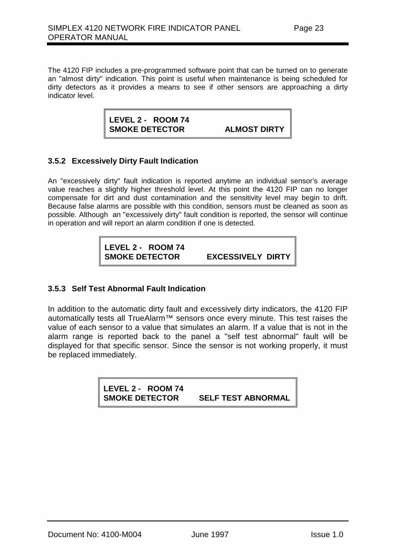
The 4120 FIP includes a pre-programmed software point that can be turned on to generatean "almost dirty" indication. This point is useful when maintenance is being scheduled fordirty detectors as it provides a means to see if other sensors are approaching a dirtyindicator level.
LEVEL 2 - ROOM 74SMOKE DETECTOR ALMOST DIRTY
3.5.2 Excessively Dirty Fault Indication
An "excessively dirty" fault indication is reported anytime an individual sensor’s averagevalue reaches a slightly higher threshold level. At this point the 4120 FIP can no longercompensate for dirt and dust contamination and the sensitivity level may begin to drift.Because false alarms are possible with this condition, sensors must be cleaned as soon aspossible. Although an "excessively dirty" fault condition is reported, the sensor will continuein operation and will report an alarm condition if one is detected.
LEVEL 2 - ROOM 74SMOKE DETECTOR EXCESSIVELY DIRTY
3.5.3 Self Test Abnormal Fault Indication
In addition to the automatic dirty fault and excessively dirty indicators, the 4120 FIPautomatically tests all TrueAlarm™ sensors once every minute. This test raises thevalue of each sensor to a value that simulates an alarm. If a value that is not in thealarm range is reported back to the panel a "self test abnormal" fault will bedisplayed for that specific sensor. Since the sensor is not working properly, it mustbe replaced immediately.
LEVEL 2 - ROOM 74SMOKE DETECTOR SELF TEST ABNORMAL

Page 24 SIMPLEX 4120 NETWORK FIRE INDICATOR PANELOPERATOR MANUAL
Document No.: 4100-M004 June 1997 Issue 1.0
SECTION 4 - RS-232 INTERFACE
Up to five RS-232 ports are available in the 4120 FIP. The RS-232 interface option supportsboth printers and video terminals to annunciate alarm, isolate and fault conditions.
4.1 RS-232 PORT ACCESS LEVELS
The 4120 FIP interface panel, and each RS-232 Interface Port configured for a videoterminal, are programmed to allow certain operations at each access level. You must be“logged in” at the required access level or higher to perform the various system operations.Up to 20 operators are allowed to log in at the various passcode access levels. The numberof operators, passcode access levels, and the allowed operations are programmed into thesystem dependent on the customer requirements.
If a port is not configured to annunciate a class of events, such as isolate conditions, you willnot be able to acknowledge those points with the video terminal keyboard, even though thevideo terminal is connected to that port, regardless of the passcode level entered. Table 1lists the default protection levels for the RS-232 interface. These levels are programmed tomeet customer requirements.
Table 1RS-232 Interface Default Protection Levels
EVENT DEFAULT
Alarm Silence 1 System Reset 1 Alarm Acknowledge 1 Fault Acknowledge 1 Isolate Acknowledge 1
Clear Historical Logs Alarm 3 Fault 3
NOTE: Access level from the RS-232 video terminal/keyboard port is separate fromthe interface panel access level.
4.2 THE VIDEO TERMINAL
The video terminal, or CRT (for the Cathode Ray Tube video display), provides annunciationand system control from the CRT display keyboard. This allows you to use the CRT tocontrol most of the functionality of the system. The CRT allows you to perform the followingprocedures from its keyboard.

SIMPLEX 4120 NETWORK FIRE INDICATOR PANEL Page 25OPERATOR MANUAL
Document No: 4100-M004 June 1997 Issue 1.0
• Log In• Log Out• Acknowledge Condition Changes• Perform System Reset Procedures• View and Print Historical Logs• view Current Abnormal Conditions• Perform Alarm Silence Procedures• Print TrueAlarmTM Reports
4.2.1 CRT Function Key Definitions
The Function Keys on the CRT keyboard are used to control the various system operations.Table 2 defines the various keys and their uses.
Table 2Function Key Definitions *
FUNCTION KEY DEFINITION
F2 Print Screen (Printer Required)
F3 Set-Up F18 Main Menu F19 Historical Log Menu
PF1 Acknowledge Key PF2 Alarm Silence PF3 System Reset Key PF4 Log In/Log Out Key CTRL W Refreshes Current Screen
4.2.2 Set-Up Procedure
The CRT must be set up[ correctly in order to receive and transmit data. An operator mayenter the set-up mode to verify proper configuration. However, set-up procedures areperformed by Simplex personnel and should not normally be performed by operators. (Seepublication FA4-11-224 for CRT set-up parameters.)
4.3 CRT SCREEN DISPLAYS
A variety of CRT screen displays are used to support system operations. Headerinformation is displayed on the first three lines of the screen. The first line shows the timeon the left, custom banner in the centre, and the operator on the right side of the screen.The second line shows the date on the left and the current access level on the right. Thethird line shows the overall system status. Prompt/Message information is shown on allscreens. The bottom line displays prompts, help messages, and error messages.
Page 26 SIMPLEX 4120 NETWORK FIRE INDICATOR PANELOPERATOR MANUAL
Document No.: 4100-M004 June 1997 Issue 1.0
These screens tell you what to do and when to do it. CRT screen displays are shown inFigures 6 through 10.
4.3.1 CRT Main Menu Screen
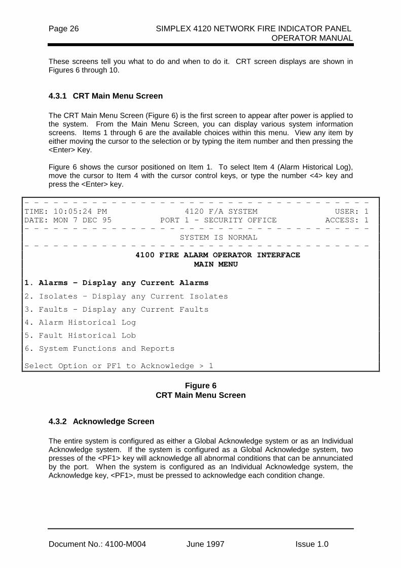
The CRT Main Menu Screen (Figure 6) is the first screen to appear after power is applied tothe system. From the Main Menu Screen, you can display various system informationscreens. Items 1 through 6 are the available choices within this menu. View any item byeither moving the cursor to the selection or by typing the item number and then pressing the<Enter> Key.
Figure 6 shows the cursor positioned on Item 1. To select Item 4 (Alarm Historical Log),move the cursor to Item 4 with the cursor control keys, or type the number <4> key andpress the <Enter> key.
- - - - - - - - - - - - - - - - - - - - - - - - - - - - - - - - - - - -TIME: 10:05:24 PM 4120 F/A SYSTEM USER: 1DATE: MON 7 DEC 95 PORT 1 - SECURITY OFFICE ACCESS: 1- - - - - - - - - - - - - - - - - - - - - - - - - - - - - - - - - - - - SYSTEM IS NORMAL- - - - - - - - - - - - - - - - - - - - - - - - - - - - - - - - - - - -
4100 FIRE ALARM OPERATOR INTERFACE MAIN MENU
1. Alarms - Display any Current Alarms
2. Isolates - Display any Current Isolates
3. Faults - Display any Current Faults
4. Alarm Historical Log
5. Fault Historical Lob
6. System Functions and Reports
Select Option or PF1 to Acknowledge > 1
Figure 6CRT Main Menu Screen
4.3.2 Acknowledge Screen
The entire system is configured as either a Global Acknowledge system or as an IndividualAcknowledge system. If the system is configured as a Global Acknowledge system, twopresses of the <PF1> key will acknowledge all abnormal conditions that can be annunciatedby the port. When the system is configured as an Individual Acknowledge system, theAcknowledge key, <PF1>, must be pressed to acknowledge each condition change.

SIMPLEX 4120 NETWORK FIRE INDICATOR PANEL Page 27OPERATOR MANUAL
Document No: 4100-M004 June 1997 Issue 1.0
All conditions which can be displayed at the CRT can be acknowledged at the CRT,provided that the user has logged in at a sufficient access level. A tone on the CRT soundsto indicate unacknowledged conditions. (The tone can be silenced with the <PF1> key.)When an abnormal condition occurs, the user must select the appropriate acknowledgescreen. The Header information on the screen indicates the number of abnormal conditionswhich can be annunciated by the CRT, and not necessarily the total number of abnormalconditions in the system. To acknowledge an abnormal condition, press the <PF1> keywhile in the acknowledge screen. The displayed condition will stop flashing, but will stillindicate the abnormal condition. When all abnormal conditions have been acknowledged,the user can return to the Main Menu by pressing the <F18> key.
As with the operator information, alarms have priority over isolates and fault conditions.Multiple conditions are displayed in chronological order. Should multiple unacknowledgedconditions occur, no unacknowledged event is allowed to scroll off the screen. If moreunacknowledged conditions exist in the system than can fit on the screen, the :oldest”unacknowledged point is displayed first. After that condition is acknowledged, it scrolls offthe top of the screen and is replaced by the next oldest condition.
The acknowledge screens are dynamic, and information is updated once per second.Follow the prompts at the bottom of the screen (shown in Figure 7) to silence signals(<PF2> key), or to reset the system (<PF3> key). When the system has reset, press the<PF1> key to acknowledge the condition change.
- - - - - - - - - - - - - - - - - - - - - - - - - - - - - - - - - - - -TIME: 10:18:15 PM 4120 F/A SYSTEM USER: 1DATE: MON 7 DEC 95 PORT 1 - SECURITY OFFICE ACCESS: 1- - - - - - - - - - - - - - - - - - - - - - - - - - - - - - - - - - - - ALARMS=1 ISOLATES=0 FAULTS=0- - - - - - - - - - - - - - - - - - - - - - - - - - - - - - - - - - - -10:09:27 pm MON 7 DEC 95 SECOND FLOOR, EAST WING, ROOM 14 MANUAL CALL POINT ALARM
PF1=ACK, PF2=Silence, PF3=System Reset, PF4=Login, F18=Main Menu
Figure 7CRT Acknowledge Screen
4.3.3 Log In Screen
It may be necessary to increase your CRT/Keyboard access level in order to acknowledgean abnormal condition. With the Main Menu displayed on the CRT screen, press the <PF4>key. A prompt will appear on the screen to “Enter your passcode”. (See Figure 8.)
Up to 19 passcodes are available to support user requirements. The passcode, inconjunction with the access level entered, determines if the operator can perform therequired system functions.
Enter your passcode, and press the <Enter> key. The user number will appear in theHeader information at the top right hand corner of the screen. The operator access level isalso displayed. Your passcode is now shown on the screen for security reasons. Instead,the screen shows “XXX”.

Page 28 SIMPLEX 4120 NETWORK FIRE INDICATOR PANELOPERATOR MANUAL
Document No.: 4100-M004 June 1997 Issue 1.0
- - - - - - - - - - - - - - - - - - - - - - - - - - - - - - - - - - - -TIME: 10:06:31 PM 4120 F/A SYSTEM USER: 1DATE: MON 7 DEC 95 PORT 1 - SECURITY OFFICE ACCESS: 1- - - - - - - - - - - - - - - - - - - - - - - - - - - - - - - - - - - - SYSTEM IS NORMAL- - - - - - - - - - - - - - - - - - - - - - - - - - - - - - - - - - - -
4100 FIRE ALARM OPERATOR INTERFACE MAIN MENU
1. Alarms - Display any Current Alarms
2. Isolates - Display any Current Isolates
3. Faults - Display any Current Faults
4. Alarm Historical Log
5. Fault Historical Lob
6. System Functions and Reports
Enter your passcode or ENTER to log out> XXX
Figure 8CRT Log In Screen
4.3.4 Historical Log Screen
The Historical Logs are formatted differently from the CRT Acknowledge Screens. As onthe operator interface panel, the Historical Logs are displayed with any entry number,followed by a time tag and the actual event.
The Historical Log shows all events in the system log, not just those events annunciated onthe CRT. These screens are not dynamic. They display only historical data.
The view the Historical Log Screens, you must select the type of historical log from the CRTMain Menu Screen (Figure 8). These options are the Alarm Historical Log and the FaultHistorical Log. Select the desired function either buy placing the screen cursor on thefunction name, or by pressing either the <4> key or the <5> key. Then, press the <Enter>key. A typical ALARM Historical Log is shown in Figure 9.

SIMPLEX 4120 NETWORK FIRE INDICATOR PANEL Page 29OPERATOR MANUAL
Document No: 4100-M004 June 1997 Issue 1.0
- - - - - - - - - - - - - - - - - - - - - - - - - - - - - - - - - - - -TIME: 10:18:15 PM 4120 F/A SYSTEM USER: 1DATE: MON 7 DEC 95 PORT 1 - SECURITY OFFICE ACCESS: 1- - - - - - - - - - - - - - - - - - - - - - - - - - - - - - - - - - - - ALARMS=4 ISOLATES=0 FAULTS=0- - - - - - - - - - - - - - - - - - - - - - - - - - - - - - - - - - - -ENTRY 1 10:09:27 pm MON 7 DEC 95 SECOND FLOOR, EAST WING, ROOM 14 MANUAL CALL POINT ALARMENTRY 2 10:11:15 pm MON 7 DEC 95 SECOND FLOOR, EAST WING, ROOM 12 MONITOR ZONE ALARMENTRY 3 10:12:23 pm MON 7 DEC 95 SECOND FLOOR, EAST WING, HALL MONITOR ZONE ALARMENTRY 4 10:13:45 pm MON 7 DEC 95 SECOND FLOOR, EAST WING, ROOM 15 MONITOR ZONE ALARM
F18=Main Menu, F19=Log Menu
Figure 9CRT Alarm Historical Log Screen
4.3.5 Status Screen
When Menu Option 1, 2 or 3 is selected, the screen displays current abnormal screenconditions. The data displayed is updated once every second. The time and dateinformation indicates when the point status changed from normal to abnormal condition.
The screen format is the same as the format for the Acknowledge Screens. Flashingentries indicate unacknowledged entries. Figure 10 shows the CRT Status Screendisplaying the Current Fault List.
- - - - - - - - - - - - - - - - - - - - - - - - - - - - - - - - - - - -TIME: 11:15:11 PM 4120 F/A SYSTEM USER: 1DATE: MON 7 DEC 95 PORT 1 - SECURITY OFFICE ACCESS: 1- - - - - - - - - - - - - - - - - - - - - - - - - - - - - - - - - - - - ALARMS=0 ISOLATES=0 FAULTS=4- - - - - - - - - - - - - - - - - - - - - - - - - - - - - - - - - - - -10:19:29 pm MON 7 DEC 95 SECOND FLOOR, EAST WING, ROOM 14 SIGNAL CIRCUIT OPEN CIRCUIT FAULT10:21:06 pm MON 7 DEC 95 MASTER BATTERY BACKUP BATTERY STATUS IS FAULT10:27:09 pm MON 7 DEC 95 SYSTEM/TIME INVALID OR NOT SET FAULT POINT ABNORMAL10:51:00 pm MON 7 DEC 95 SECOND FLOOR, EAST WING, ROOM 15 FIRE MONITOR ZONE ISOLATE FAULT
PF1=ACK, PF2=Silence, PF3=System Reset, PF4=Login, F18=Main Menu
Figure 10CRT Status Screen

Page 30 SIMPLEX 4120 NETWORK FIRE INDICATOR PANELOPERATOR MANUAL
Document No.: 4100-M004 June 1997 Issue 1.0
4.4 THE SYSTEM PRINTER
The system uses a printer to provide a hard copy of the system’s current status. Thesystem supports both DC and AC printers.
A DC printer printline is 40 characters long. A typical DC printer printout is shown in Figure11.
10:09:27 pm MON 7 DEC 95 2ND FLOOR EAST WING, ROOM 14 MANUAL CALL POINT ALARM 10:10:36 pm MON 7 DEC 95 ALARM ACKNOWLEDGED AT MAIN PANEL 10:15:12 pm MON 7 DEC 95 ALARM SILENCE IN PROGRESS 10:16:09 pm MON 7 DEC 95 SIGNALS SILENCED AT MAIN PANEL 10:17:10 pm MON 7 DEC 95 SYSTEM RESET IN PROGRESS AT MAIN PANEL 10:19:12 pm MON 7 DEC 95 SYSTEM RESET IN PROGRESS 10:19:33 pm MON 7 DEC 95 2ND FLOOR EAST WING, ROOM 14 MANUAL CALL POINT NORMAL 10:19:45 pm MON 7 DEC 95 2ND FLOOR EAST WING, ROOM 14 NO ALARMS PRESENT, SYSTEM RESET COMPLETE
Figure 1140 Character Line Width Printout
The AC printer prints only in black, with line widths of 80 characters. A typical AC printer isshown in Figure 12.
10:09:27 pm MON 7 DEC 95 2ND FLOOR EAST WING, ROOM 14 MANUAL CALL POINT ALARM 10:10:36 pm MON 7 DEC 95 ALARM ACKNOWLEDGED AT CRT 10:15:12 pm MON 7 DEC 95 ALARM SILENCE IN PROGRESS 10:16:09 pm MON 7 DEC 95 SIGNALS SILENCED AT CRT 10:17:10 pm MON 7 DEC 95 SYSTEM RESET IN PROGRESS AT CRT 10:18:12 pm MON 7 DEC 95 SYSTEM RESET IN PROGRESS 10:19:33 pm MON 7 DEC 95 2ND FLOOR EAST WING, ROOM 14 MANUAL CALL POINT NORMAL 10:19:45 pm MON 7 DEC 95 2ND FLOOR EAST WING, ROOM 14 NO ALARMS PRESENT, SYSTEM RESET COMPLETE
Figure 1280 Character Line Width Printout

SIMPLEX 4120 NETWORK FIRE INDICATOR PANEL Page 31OPERATOR MANUAL
Document No: 4100-M004 June 1997 Issue 1.0
SECTION 5 - MAPNET II®
The MAPNET II® option allows the use of addressable devices and TrueAlarm™ sensorswith the system. Addressable devices communicate the exact location of an alarm to the4120 FIP operator interface panel, improving recognition of the condition and thesubsequent response. It also pinpoints the precise location of fault conditions via thecustom label description.
A TrueAlarm™ sensor measures smoke density or heat intensity, but has not self-containedalarm set point. The alarm set point is programmed into the network node. Thus, thedecision is made by the network node, rather than by the sensor.
5.1 MAPNET II® ALPHANUMERIC DISPLAYS
When a MAPNET II device changes to an abnormal state, or the operator enters a MAPNETII® device address, the 4120 FIP alphanumeric display shows the current status of theMAPNET II® device. After entering a MAPNET II® device address, press the <FUNCTION>key on the operator interface panel to display additional device information.
For the TrueAlarm™ sensor, device information reported back to the 4120 FIP operatorinterface panel also includes data about the condition of the sensor itself. For example, thesensor might report that it is dirty or excessively dirty.
5.2 MAPNET II® POINT ADDRESSING
Each MAPNET II® device must have a point address in order to communicate with the 4120FIP. These point addresses, along with their custom labels, are located in theProgrammer’s Report. The Programmer’s Report shows the address for each device,separated by hyphens. Hyphens must be used when entering a MAPNET II® address intothe system. An example of a MAPNET II® device address is “3:M1-5”. The “3:” portion ofthe address identifies the owning node. The “M1” portion of the address identifies theMAPNET II® channel, channel 1. The “5” portion of the address identifies the devicenumber, number 5. MAPNET II® channel numbers range from 1 through 9, and 0, withMAPNET II® channel 0 actually being channel 10.
5.2.1 How to Display a MAPNET II® System Point
See Section 5, “How to Display MAPNET II® Point Status” for MAPNET II® operations. Thisprocedure also shows how to use the Programmer’s Report to find MAPNET II® addresses.
5.2.2 What To Do If a MAPNET II® Point Will Not Reset
If a MAPNET II® device will not reset, you may decide to isolate the point with the<DISABLE> key. When the isolate procedure is performed, a System Fault occurs toremind you that the point is isolated. The isolate procedure is the same for all systempoints. (See Section 2, “How to Isolate/De-Isolate a Zone”.) Maintenance personnel mustbe called immediately to repair the malfunction.
After the MAPNET II® point is repaired, you can de-isolate the point again. (Section 2, “Howto Isolate/De-Isolate a Zone”>) This procedure is the same for all system points.
Page 32 SIMPLEX 4120 NETWORK FIRE INDICATOR PANELOPERATOR MANUAL
Document No.: 4100-M004 June 1997 Issue 1.0
SECTION 6 - ADVANCED FUNCTIONS
When more involved functionality/control is required, simply open the "Access Door" toexpose the additional keys which are used for advanced functions. Figure 13 belowshows the panel with the access door open and the advanced function keys.
Figure 13Operator Interface Panel Controls and Indicators
6.1 CONTROL KEYS
Five "CONTROL" keys with their individual LED’s are located on the far left of the panelNormally, these keys and LEDs will be concealed by the access door. A custom label isused to identify the desired function. Typical functions for these keys will be used for thefollowing functions:
➤ Brigade Test➤ Battery Test➤ Alarm Test➤ Fault Test➤ ACF Isolate
Figure 14Control Keys
CAUTION
OPERATION OF THESE KEYS MAY CAUSE ALARM SIGNALS TO SOUND OR FAULTCONDITIONS TO BE GENERATED BY THE SYSTEM.

SIMPLEX 4120 NETWORK FIRE INDICATOR PANEL Page 33OPERATOR MANUAL
Document No: 4100-M004 June 1997 Issue 1.0
These keys can be pressed anytime, and the key feedback (beep) may be the onlyacknowledgment of the action. Typically, the LED will track the function and illuminate eachtime its respective key is pressed.
6.2 FUNCTION KEYS
Four function keys (<F1>, <F2>, <F3>, and <F4>) are located directly above thealphanumeric display (refer Figure 15). Within the Main Function Menu options, these keydefinitions will change as required to perform specific actions for selected Main FunctionMenu options. Some menu options may not require any key operation, while others willrequire all four. The definitions of each physically activated key will be shown on the top lineof the alphanumeric display as an aid to the user. A function key does not require any otherkey to be pressed to activate its function. Pressing a key immediately performs its definedtask. Pressing a key which has no defined action for the current function has no effect,however, the tone-alert will acknowledge the key press with a "beep".
These four keys are associated with advanced functions of the system within the MainFunction Menu options, and within point displays. The <F1>, <F2>, <F3>, and <F4> keyshave extended actions defined during point displays used in conjunction with the<FUNCTION> key.
Figure 15Four Functions Keys F1 - F4
6.3 HOW TO SET TIME AND DATE
The following is an example of how to use the function keys to set the time and date.
A. Press the <MENU> key. The following will be shown on the alphanumeric display.
Press <NEXT> or <PREVIOUS> to scrollChange Access Level

Page 34 SIMPLEX 4120 NETWORK FIRE INDICATOR PANELOPERATOR MANUAL
Document No.: 4100-M004 June 1997 Issue 1.0
B. Press the <NEXT> key. The following is displayed:
Press <NEXT> or <PREVIOUS> to scrollSet Time and Date
C. Press the <ENTER> key. The current time and date information is displayed along withinstructions:
Press <FUNC> to change time and date0:09:23 FRI 01 JAN 88
D. Press the <FUNC> key. The cursor, current time and date along with function keydefinitions are displayed:
F1=Left F2=Right F3=Inc F4= Dec0:09:23 FRI 01 JAN 88
NOTE: The cursor is positioned under the hour. Function key F1 will move the cursorleft. Function key F2 will move the cursor right. Function key F3 will increasethe data above the cursor . Function key F4 will decrease the data above thecursor. Set the time 1 minute ahead of source time.
E. Use the required function key to position the cursor under the data to be changed (hour,minutes, seconds, date of month, month, and year). Day of week is set by the system.Time entered does not start until the <ENTER> key is pressed.
F. Use Function key F3 or F4 to increase or decrease data, as required.
When time and date are correct, press the <ENTER> key. The display will show theupdated time and date. The time entered will not start until the <ENTER> key ispressed.
Press <FUNC> to change time and date22:04:46 SUN 01 MAY 95
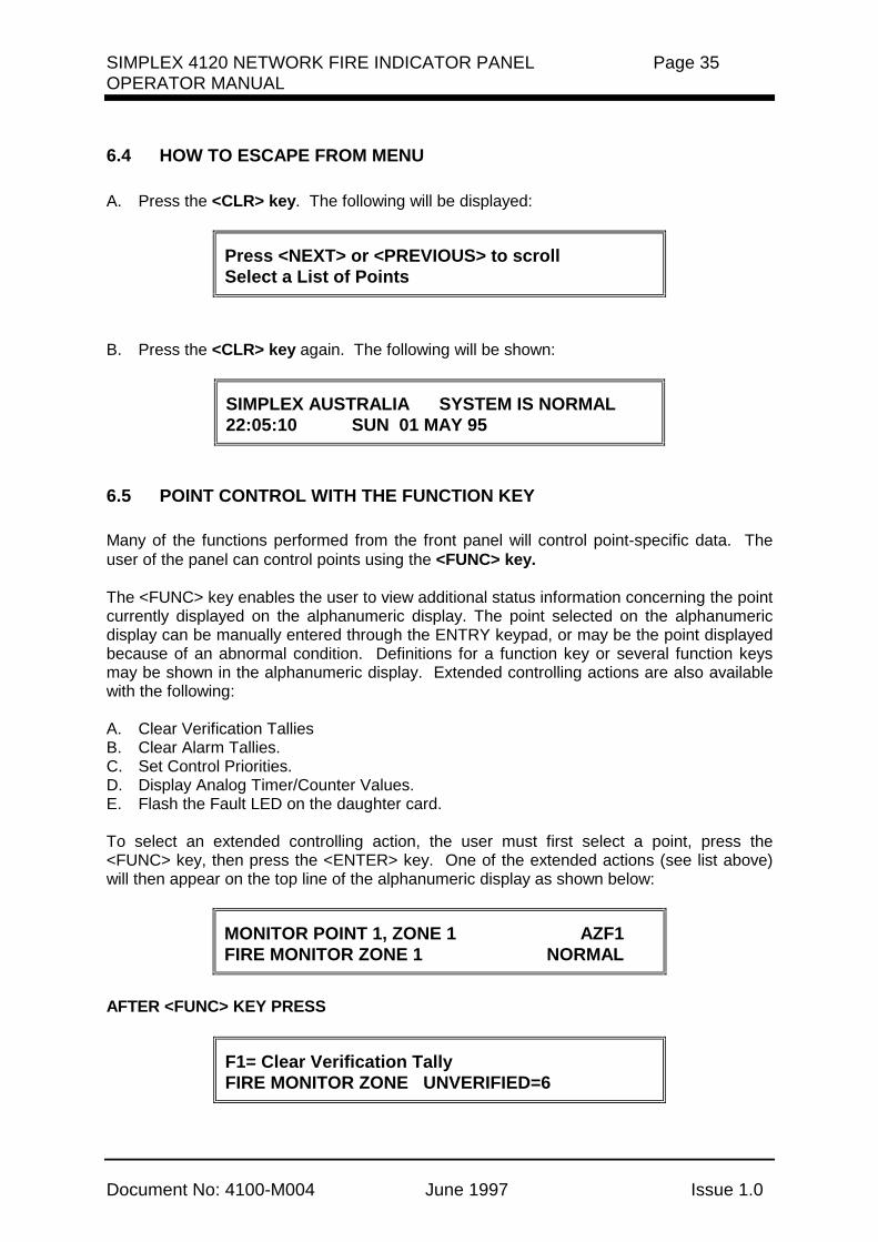
SIMPLEX 4120 NETWORK FIRE INDICATOR PANEL Page 35OPERATOR MANUAL
Document No: 4100-M004 June 1997 Issue 1.0
6.4 HOW TO ESCAPE FROM MENU
A. Press the <CLR> key. The following will be displayed:
Press <NEXT> or <PREVIOUS> to scrollSelect a List of Points
B. Press the <CLR> key again. The following will be shown:
SIMPLEX AUSTRALIA SYSTEM IS NORMAL22:05:10 SUN 01 MAY 95
6.5 POINT CONTROL WITH THE FUNCTION KEY
Many of the functions performed from the front panel will control point-specific data. Theuser of the panel can control points using the <FUNC> key.
The <FUNC> key enables the user to view additional status information concerning the pointcurrently displayed on the alphanumeric display. The point selected on the alphanumericdisplay can be manually entered through the ENTRY keypad, or may be the point displayedbecause of an abnormal condition. Definitions for a function key or several function keysmay be shown in the alphanumeric display. Extended controlling actions are also availablewith the following:
A. Clear Verification TalliesB. Clear Alarm Tallies.C. Set Control Priorities.D. Display Analog Timer/Counter Values.E. Flash the Fault LED on the daughter card.
To select an extended controlling action, the user must first select a point, press the<FUNC> key, then press the <ENTER> key. One of the extended actions (see list above)will then appear on the top line of the alphanumeric display as shown below:
MONITOR POINT 1, ZONE 1 AZF1FIRE MONITOR ZONE 1 NORMAL
AFTER <FUNC> KEY PRESS
F1= Clear Verification TallyFIRE MONITOR ZONE UNVERIFIED=6

Page 36 SIMPLEX 4120 NETWORK FIRE INDICATOR PANELOPERATOR MANUAL
Document No.: 4100-M004 June 1997 Issue 1.0
The user will then press the <FUNC> key to view the status of the selected point. Thetone-alert will beep and a different status is shown on the alphanumeric display each timethe <FUNC> key is pressed. In some cases, the user can then take action to change pointdata. This technique may be used for each of the extended controlling actions.
The extended controlling action shown above is for monitor zones.
6.6 DISPLAY/ACTION KEYS
The "DISPLAY/ACTION" keypad provides eleven keys which allow users with appropriateaccess level, the ability to perform controlling functions on the system zones, MAPNETdevices, signals, and auxiliary control relays. Six keys are associated with Display whilefive keys are Action keys.
Action key presses require a confirmation <ENTER> key to be pressed before performingthe action on the point identifier displayed. These "DISPLAY/ACTION" keys are concealedby the access door.
Figure 16Display / Action Keys
The following keys are DISPLAY keys:
➤ FUNCTION ➤ MENU ➤ PREVIOUS ➤ NEXT ➤ LAMP TEST ➤ DISPLAY TIME
The purpose of each DISPLAY key is described in the following paragraphs

SIMPLEX 4120 NETWORK FIRE INDICATOR PANEL Page 37OPERATOR MANUAL
Document No: 4100-M004 June 1997 Issue 1.0
6.6.1 Function Key Operation
The <FUNCTION> key is used to obtain more information concerning the point in thedisplay. These points can be brought up on the main menu as previously explained.<FUNCTION> key presses will scroll through all the status information. This data will bedisplayed on the bottom line. The top line will contain the 40 character label of definitionsfor <F1>, <F2>, <F3> and <F4> keys.
A point will normally be displayed with its forty character custom label on the top line. If nocustom label exists for the point, the top line will display the point identifier.
The bottom line will contain the device type and its present status. Point types are assignedwhen the system is configured, and are determined by their card type and the physicaldevices on its zones.
The following are available for display on the alphanumeric display.
A. Point address and Zone number.B. Card type and Point type.C. Present Status (Normal, Alarm, Fault).D. Disconnect/Isolate Status.E. McCulloh Fault (Status of Class "A" Cards).F. Relay status for Control or Signal Points.G. Verification Tallies for Verification Zones.H. Coding Status for Coded Zones.I. Control Priority for Relays.J. Feedback Point Status for Relays.
In addition to the items above, the following items are for TrueAlarm sensors only:
• Present sensitivity selected• Average value• Alarm value• Current value (per cent of alarm)• Peak value (per cent of Alarm)
6.6.2 MENU Key
The <MENU> key will call up the Main Function Menu Option List and display the first optionon the list.
The Main Function Menu provides operations which are separate from those used for firealarm conditions. These non-critical functions are selected with the <MENU> key.The <NEXT> and <PREVIOUS> keys are used to scroll through the menu options. The<ENTER> key selects the displayed option. The following are the Main Function Menus:

Page 38 SIMPLEX 4120 NETWORK FIRE INDICATOR PANELOPERATOR MANUAL
Document No.: 4100-M004 June 1997 Issue 1.0
• Change Access Level?• Set Time and Date?• Display Historical Alarm Log?• Display Historical Fault Log?• Select a List of Points?• Display Software Revision Level?• Display Card Status?• Print Report?• Printer Options?• Enable Walk Test?• Display Network Node Identification?• Network Diagnostic Functions?• Display System CPU and Idle Time?• Exit Menu List?
6.6.3 PREVIOUS Key
The <PREVIOUS> key is used in Main Function Menu options and in point list displays toscroll to the previous option, item, or point. This key works like the <ACK> keys for Alarm,Supervisory, and Fault conditions. Holding this key in will continuously scroll backward. Ifthe first item in the list or menu has been shown, pushing the <PREVIOUS> key will causethe list to wrap around backwards to the end of the list.
6.6.4 NEXT Key
The <NEXT> key is used in Main Function Menu options and in point list displays to scroll tothe next option, item, or point. This key also works like the <ACK> keys for Alarm,Supervisory, and Fault conditions. Holding this key in will continuously scroll forward.Whenever the last item in a list or menu has been shown, pressing the <NEXT> key willagain cause the list to wrap around to the start of the list.
6.6.5 LAMP TEST Key
Pressing the <LAMP TEST> key will turn on the five Control Key LED’s, Isolate LED,System Alarm LED, System Fault LED, and the LEDs on local LED/switch modules. Allsegments on the alphanumeric display will be turned on as a test pattern. After a threeseconds sustained press, the Tone-alert will be turned on. When the <LAMP TEST> keyhas been released, all LEDs, alphanumeric display, and tone-alert will be restored to theirprevious states.
6.6.6 Action Keys
There are six action keys on the display/action keypad:
➤ Isolate (Isolating a point) ➤ Enable (De-Isolating a point) ➤ Off - Turning a point OFF ➤ On - Turning a point ON ➤ Auto - Return a point to Auto Control

SIMPLEX 4120 NETWORK FIRE INDICATOR PANEL Page 39OPERATOR MANUAL
Document No: 4100-M004 June 1997 Issue 1.0
6.6.7 Entry Keypad
The ENTRY keypad is located to the far right on the operator interface panel and isconcealed by the access door. There are fourteen keys on this keypad as shown in Figure17.
Figure 17ENTRY Keypad
NUMERIC KEY PREFIX DESCRIPTION
1 = Monitor zone #2 = Signal Zone #3 = Auxiliary Zone #4 = Feedback Zone #5 = I/O Zone (Point) #6 = MAPNET II®
7 = Digital Pseudo Point #8 = Analogue Pseudo Point #9 = List Pseudo Point #0 = Numeric System Address #– = Network Node and Point #
These keys are used to enter passcodes, identifiers, or numeric data for the system.Whenever the system expects numeric data input, the user is notified with a prompt.Numeric data input requires an <ENTER> key press to complete the keypad entry. Numerickeys also double as "prefix" keys. When entering a point, a prefix key must be used toidentify how the entry is made. Pressing the zone key (key 1) indicates that the next numericentry is a zone number. Pressing the address key (key 0) indicates that an address identifieris entered.
6.7 HOW TO ENTER A PREFIX
When interrogating the system about a specific network point, the first two entriesfrom the ENTRY keypad must be prefix entries. The first prefix entry selects thenetwork node number. The second prefix entry selects the monitor point, signalpoint, auxiliary point, feedback point, graphic input/output point, digital pseudo point,analogue pseudo point, list pseudo point, or point address format.
When you press the first prefix key (the <NET –> key), the system software requeststhe network node number, as shown below.
Please input the Network Node NumberNETWORK:

Page 40 SIMPLEX 4120 NETWORK FIRE INDICATOR PANELOPERATOR MANUAL
Document No.: 4100-M004 June 1997 Issue 1.0
Enter the network node number and press the <ENTER> key, as shown below.
Please input the Network Node NumberNETWORK: 2
As soon as the <ENTER> key is pressed, the display changes and prompts you for theZone or Address prefix, as shown below.
Please enter a ZONE or ADDRESS prefixNETWORK: 2:
If the second prefix key pressed is the <ZONE 1> key, the display appears as shown below.
Please enter a ZONE or ADDRESS prefixNETWORK: 2:ZN
Press the <ENTER> key. As soon as the <ENTER> key is pressed, the display changesand prompts you for the Zone number, as shown below.
Please input a ZONE numberNETWORK: 2:ZN
The zone number for the selected prefix can now be entered. The input must be terminatedwith an <ENTER> key press. If the identifier represents a valid point in the system, thepoint is displayed as shown in the example below (20 was entered for this example).
Please input a ZONE numberNETWORK: 2:ZN20
If the keypad input is invalid, the incorrect keypad entry is held in the display on the bottomline along with the error message on the top line as shown below.
ERROR. . . INVALID IDENTIFIERNETWORK: 2:ZNXX
NOTE: XX equals the invalid identifier.
This data is briefly display. Then, the user is prompted to enter a ZONE or ADDRESS prefixas shown below:
Please enter a ZONE or ADDRESS prefix

SIMPLEX 4120 NETWORK FIRE INDICATOR PANEL Page 41OPERATOR MANUAL
Document No: 4100-M004 June 1997 Issue 1.0
A complete listing of system points is located within the Programmer’s Report. Each systempoint has an associated Custom Label which identifies a specific location within the building.Pseudo points have Custom Labels which identify their purpose.
6.8 HOW TO DISPLAY MAPNET II® POINT STATUS
Shown below is an example of a Programmer’s Report entry describing a MAPNET II® point.
2: M1-2 3RD FLOOR EAST WING ROOM 13 ALARM MBZAM
The “2:” portion of the address identifies the owning node. The “M1” identifies the MAPNETII® card or Channel; the “-2” identifies the device. The custom label is “3RD FLOOR EASTWING, ROOM 13”. When entering MAPNET II® Zone Names, a hyphen must be used toseparate the channel from the device.
To display the status of the above MAPNET II® point, perform the following.
1. Enter the network node number. (See “How to Enter a Prefix”.)
2. Press the <MAP> key (key 6). The alphanumeric display prompts the operator for aMAPNET II® Point Address input as shown below.
Please input Channel-Device (C-DDD)NETWORK: 2:M
NOTE: The display shows (C-DDD). “C” is the MAPNET II® channel (1 to 9, and 0);“DDD” is the device number (1 to 127).
3. Use the ENTRY keypad to enter the MAPNET II® Point Address, such as M1-2, thenpress the <ENTER> key. The alphanumeric display shows the MAPNET II® point statusand its custom label as shown below.
3RD FLOOR EAST WING ROOM 13FIRE MONITOR ZONE NORMAL
4. Press the <FUNCTION> key as required to display additional point status information.
NOTE: Any system point may be viewed on the alphanumeric display using the aboveprocedure. Press the required Prefix keys; then, use the Programmer’sReport to identify the required point address. Enter the required point address.Press the <FUNCTION> key to display information about the point youentered.
An example of the Programmer’s Report is shown in Figure 18.

Page 42 SIMPLEX 4120 NETWORK FIRE INDICATOR PANELOPERATOR MANUAL
Document No.: 4100-M004 June 1997 Issue 1.0
- - - - - - - - - - - - - - - - - - - - - - - - - - - - - - - - - - - -NETWORK INTERFACE REPORT
FLOORS 4 THRU 6 PAGE 4792A3002A node:2 rev:3 11:05:21, TUE, 29-DEC-95- - - - - - - - - - - - - - - - - - - - - - - - - - - - - - - - - - - -
Network Node : 2Network Filename : 92A9001Master Timekeeper : NOAnnunciate Missing Node : NO
Point Device Point Pt Typ Name Type Type Custom Label- - - - - - - - - - - - - - - - - - - - - - - - - - - - - - - - - - - - 1 PUB 2:1 COMNTBL TROUBLE COMMON TROUBLE POINT FOR NODE: 2 2 PUB P210 DIGITAL UTILITY NETWORK DETECTOR RESET 3 PUB P211 DIGITAL UTILITY NETWORK SYSTEM RESET 4 PUB P212 DIGITAL UTILITY DETECTOR/SYSTEM RESET 5 PUB P217 DIGITAL UTILITY NETWORK SIGNAL SILENCE 6 PUB P132 DIGITAL TROUBLE ANALOG SENSOR ALMOST DIRTY LOG ENABLE 7 PUB P134 DIGITAL TROUBLE CLEAR ANALOG SENSOR PEAK VALUE 8 PUB P214 DIGITAL TROUBLE CLEAR VERIFICATION TALLIES 9 PUB P187 DIGITAL UTILITY VIG & AMPLIFIER TROUBLE DISABLE513 PUB ZN1 SMONB HEAT 4TH FLOOR - HEATER BAY AREA514 PUB ZN2 SMONB HEAT 4TH FLOOR - CAFETERIA/KITCHEN515 PUB ZN3 SMONB SMOKE 4TH FLOOR - PIPEWAY AREA516 PUB ZN4 SMONB HEAT 5TH FLOOR - TOP/TRANSTUBE ROOM517 PUB ZN5 SMONB SMOKE 5TH FLOOR - MAKE-UP PUMP ROOM518 PUB ZN6 SMONB FLAME 5TH FLOOR - ROOM 227 PASSAGE519 PUB ZN7 SMONB HEAT 6TH FLOOR - WASTE GAS COMPRESSOR ROOM520 PUB ZN8 SMONB SMOKE 6TH FLOOR - FUEL HANDLING AREA521 PUB L128 LIST CONTROL SIGNALS - FLOORS 4 THRU 6522 EXT 1:P212 DIGITAL UTILITY DETECTOR/SYSTEM RESET523 EXT 1:P217 DIGITAL UTILITY NETWORK SIGNAL SILENCE524 EXT 1:L128 LIST MIXED 1ST FLOOR ALARM ZONES525 EXT 1:L129 LIST MIXED 2ND FLOOR ALARM ZONES526 EXT 1:L130 LIST MONITOR 3RD FLOOR ALARM ZONES527 EXT 1:P45 DIGITAL UTILITY DRILL SWITCH INPUT528 EXT 1:P256 DIGITAL UTILITY DOOR HOLDER BYPASS STATUS PSEUDO
Figure 18Excerpt from Typical Programmer’s Report

SIMPLEX 4120 NETWORK FIRE INDICATOR PANEL Page 43OPERATOR MANUAL
Document No: 4100-M004 June 1997 Issue 1.0
6.9 HOW TO DISPLAY THE SENSITIVITY OF A TrueAlarm™ SENSOR
Use the following procedure to determine the sensitivity of a TrueAlarm™ Sensor.
1. Using the Programmer’s Report, locate the address of the desired sensor.
NOTE: The sensor address is in the format “N:C-DDD”, where “N:” is the number ofthe sensor’s node, “C” is the MAPNET II® channel (1 through 9, and 0), and“DDD” is the sensor number (1 through 127).
2. Lower the operator interface panel cover to gain access to all of the keypads.
3. Press the first prefix key (the <NET –> key). The system software requests the networknode number, as shown below.
Please Input the Network Node NumberNETWORK:
4. Enter the network node number. (For this example, the network node number is “2”.)
Please Input the Network Node NumberNETWORK: 2
5. Press the <ENTER> key. As soon as the <ENTER> key is pressed, the displaychanges and prompts you for the Zone or Address prefix, as shown below.
Please enter a ZONE or ADDRESS prefixNETWORK: 2:
6. Press the <MAP 6> key on the ENTRY keypad. The alphanumeric display nowprompts you for the MAPNET II® channel and device number.
Please input Channel-Device (C-DDD)NETWORK: 2:M
7. Using the ENTRY keypad, press the appropriate numeric key for the sensor’s channel(1 through 9, and 0), the hyphen <NET –> key, and the appropriate number key(s) (1through 127) for the sensor’s device number. Then, press the <ENTER> key. Thedisplay now shows you the location (custom label) and status of the sensor.
BLDG. 21-1 MECHANICAL ROOMSMOKE DETECTOR NORMAL

Page 44 SIMPLEX 4120 NETWORK FIRE INDICATOR PANELOPERATOR MANUAL
Document No.: 4100-M004 June 1997 Issue 1.0
8. To verify the sensor’s MAPNET II® point address, press the <FUNCTION> key on theDISPLAY/ACTION keypad. The display now looks like the example shown below.
POINT ADDRESS: 9-529NETWORK: 2:M1-15 FROM: 2:513
• The network node number, channel and address displayed must match the addressentered in Steps 5 and 6.
NOTES:
1. Pressing the <FUNCTION> key allows you to view status information on the sensorthat was verified in Step 8. Pressing the <FUNCTION> key or the <NEXT> key onthe DISPLAY/ACTION keypad repeatedly allows you to view 13 more status displayson this particular sensor; using the <PREVIOUS> key allows you to go back andlook at a previously viewed display.
2. Status displays 9 through 12 are explained below. The displays reveal the followinginformation: sensor’s sensitivity as programmed at its node; average sensor valueand sensor value needed to cause an alarm; current sensor value; and highest(peak) sensor value to date.
9. To display the sensitivity programmed for the sensor, press the <FUNCTION> key sixmore times.
NOTE: If you accidentally press the <FUNCTION> key more than six times, you cango back one display at a time using the <PREVIOUS> key on theDISPLAY/ACTION keypad.
• The display shows part of the custom label (location) along with the sensor’s presentsensitivity.
<F1> = Change <F2> = Default <ENTER> = SavePRESENT SENSITIVITY SELECTED = 2.5%SMOKE
10. Press the <FUNCTION> key again to display the sensor’s average and alarm value.
• The display shows sensor location, average sensor value, and sensor value neededto cause an alarm condition.
BLDG. 21-1 MECHANICAL ROOMAVERAGE VALUE = 90 / ALARM LEVEL = 158
• This display shows an average value of 90 for the last 2048 values reported by thesensor. It also shows that a sensor value of 158 is needed to cause an alarmcondition for the sensor.

SIMPLEX 4120 NETWORK FIRE INDICATOR PANEL Page 45OPERATOR MANUAL
Document No: 4100-M004 June 1997 Issue 1.0
11. Press the <FUNCTION> key again to display the sensor’s current value.
• The display shows sensor location and present sensor value.
BLDG. 21-1 MECHANICAL ROOMVALUE = 90 / 0% OF ALARM / 0.0% SMOKE
• This display shows the sensor is currently reporting a value of 90. It also shows thatthe value of 90 represents the following: 0% of the required increase needed tocause an alarm and 0.0% content of smoke in the air as seen by the sensor.
12. Press the <FUNCTION> key again to display the sensor’s highest (peak) value to date.
• The display shows that pressing F1 clears a peak value (given a proper operatoraccess level).
F1 = Clear PEAK valuePEAK = 92 / 2% OF ALARM / 0.0% SMOKE
• This display shows the sensor’s highest value to date is 92. It also shows that thevalue of 92 represents the following: 2% of the increase needed to cause an alarmand 0.0% equivalent percentage of smoke for the 2% increase.
13. To exit the sensor’s viewing mode, press the <CLR> key twice.
6.10 ADDITIONAL KEYS
6.10.1 Enter
The <ENTER> key is used to complete keypad entries. It is also used to select menuoptions and print list elements.
6.10.2 Clear
The <CLR> key press is used to exit from a Main Menu Function option or abort anincomplete keypad entry. In most cases, the current display will clear and will back up onelevel. Multiple <CLR> key presses will continue to back up until the top level is reached.The top level will display the “SYSTEM IS NORMAL” followed by time and date, or the totalnumber of abnormal conditions.
6.10.3 Hyphen
The hyphen (–) portion of the <NET–> key is used to set the limits/boundaries for cardaddress, point numbers, and sub-point numbers during keypad entries.

Page 46 SIMPLEX 4120 NETWORK FIRE INDICATOR PANELOPERATOR MANUAL
Document No.: 4100-M004 June 1997 Issue 1.0
6.10.4 Delete
The <DEL> key acts as a delete key during keypad inputs. It inserts a blank space in thecurrent location and backs up one position.
6.11 POINT SELECTION
6.11.1 Selecting Points Using Lists
Many of the functions performed from the operator interface panel display point specificdata. Every system point is part of the “Select A List of Points” list in the main menu. Allpoints can be displayed sequentially by address order using this list option. To facilitate thesearch for a particular point, lists may be selected by type groupings (monitors, signals,auxiliary, input/output, pseudo points, etc.). A list of points may be selected, then scrolledthrough by using the <NEXT> and <PREVIOUS> keys. Selecting a list of points willexpedite the search for a specific point with a minimum of scrolling.
The following lists are available for selection with the “Select a List of Points” option from theMain Function Menu:
• All Monitor Zones (Not available for 4120 FIP)• All Signal Points (Not available for 4120 FIP)• All Auxiliary Relay Points (Not available for 4120 FIP)• All Auxiliary Feedback Points (Not available for 4120 FIP)• All zones of 24-Point I/O Card (Not available for 4120 FIP)• All Digital Pseudo Points• All Analogue Pseudo Points• All List Pseudo Points• All Points by Address List• All Network Points.
6.11.2 Selecting Points Using the Keyboard
Rather than scrolling through a list, you may use the keypad to select a point. If the inputrepresents a valid point in the system, that point will be shown on the alphanumeric display.After a point has been displayed, you can scroll through all the points in the system fromthat point, or select another point directly by entering another identifier using the keypad.
You have the choice of entering a point number or an address number. The format forentering a point identifier address requires a hyphen. Only numbers and the hyphen keysare valid entries. The maximum number of digits allowed in an identifier input is eleven (11),including the hyphens, excluding the <ENTER> key.
6.11.3 Selecting Additional Lists
When an abnormal condition occurs, a record of the event is placed in one of two logsgenerated by the system, depending on the nature of the condition. These logs are:
• Historical Alarm Log• Historical Fault Log

SIMPLEX 4120 NETWORK FIRE INDICATOR PANEL Page 47OPERATOR MANUAL
Document No: 4100-M004 June 1997 Issue 1.0
6.12 OPERATOR ACCESS LEVELS
There are four operator access levels available to support the system. They are levels 1through 4. Level 1 is the lowest operator access level and does not require a passcode tobe entered to access functions identified at this level. Level 2 through 4 require a passcodeof the required level or higher to be entered prior to performing the passcode protectedfunction. Controlling actions may be classified with access levels 2 through 4. Routineactions are assigned to low access levels while access level 4 is reserved for special, highlysensitive operations (normally reserved for Simplex personnel). Entering a level 4 passcodeenables you to access all the functions of the system.
A valid passcode must contain a minimum of 3 digits and not more than 10 digits. Theavailable digits are 0 through 9. Passcodes are specified during order entry; then,programmed during system configuration. When passcodes are not specified, the followingdefault passcodes are assigned.
LEVEL PASSCODE RANK
1 NONE LOWEST2 222 SECOND3 333 THIRD (Highest Operator Access Level)4 XXX HIGHEST (Normally used by Simplex Personnel)
The operator access level defaults to level 1 when power is first applied to the system, after10 minutes of keypad inactivity, and when the user elects to log out. The <SYSTEMRESET> key press has no effect upon the access level.
The only way to increase the operator access level in the system is to select the “ChangeAccess Level?” option in the Main Function Menu. Decreasing the level resets systemaccess level to 1. Increasing the level requires a valid level 2, 3 or 4 passcode. The user isprompted to enter a passcode. The input is compared to all the valid system codes, and thesystem operator access level is set accordingly. If an invalid code is input, you will benotified with the message “ERROR. . . INVALID PASSCODE”, and will be allowed up tothree chances to enter a valid code. After three unsuccessful tries, the message “ACCESSDENIED” will be displayed for a short time. The access level will not be altered, but you willno longer be in the “Change Access Level” menu option.
If a correct passcode is entered, the message “ACCESS GRANTED” is displayed. The newoperator access level will be in effect until the keypad is inactive for 10 minutes or youmanually reset the level through the “Change Access Level” option.
While entering a passcode with the keypad, the key presses are acknowledged by a “beep”.The digits entered are not displayed. The cursor moves along, filling the position with an Xto indicate that a digit has been entered. The <DEL> key can be used to delete the lastdigit. The <ENTER> key press is required to enter the passcode into the system.
The Action Keys, ON, OFF, AUTO, ENABLE, DISABLE and the five Panel Control Keysmay have operator access levels associated with them. If such a key is pressed with aninsufficient access level, a message will inform you that the action was not taken and thekey press is ignored. The user will have to select the Main Function Menu option toincrease the access level before using the key. (See Log in Procedure for details.)

Page 48 SIMPLEX 4120 NETWORK FIRE INDICATOR PANELOPERATOR MANUAL
Document No.: 4100-M004 June 1997 Issue 1.0
The Acknowledge Keys may also require passcodes to acknowledge abnormal conditions.If you press an <ACK> key with insufficient access, an error message will be displayed. Thepoints will scroll with <ACK> key pressing to allow you to view the points on the list, but thepoints will not be acknowledged. (See Log in Procedure for details.)
6.13 POWER UP SEQUENCE
Whenever power is applied to the 4120 FIP panel, or when the 4120 FIP Master Controllermicroprocessor has been reset, the 4120 FIP self-tests its memory integrity and verifiescard configurations. Next, the 4120 FIP displays the system startup in progress messages,followed by a fault condition. Battery fault conditions normally clear automatically.
The green POWER ON LED illuminates immediately after AC power is applied to the 4120FIP. Make sure that the green LED is illuminated before connecting the battery powerharness.
IMPORTANT
To power up the 4120 FIP, apply 240 VAC to the unit. Wait until the GREEN POWERON LED has illuminate; then connect the battery power harness.
To power down the 4120 FIP, disconnect battery power harness; then, turn the 240 VACpower OFF.
SIMPLEX 4120 NETWORK FIRE INDICATOR PANEL Page 49OPERATOR MANUAL
Document No: 4100-M004 June 1997 Issue 1.0
SECTION 7 - SYSTEM TEST PROCEDURES
NOTE: These procedures should be followed when the system is installed and duringperiodic testing as required by code. Check local codes to determine how frequentyour system should be tested. Always inform appropriate personnel that you will betesting the system (Fire Brigade, etc.).
7.1 LAMP TEST
The “LAMP TEST” push-button on the operator interface panel is used to determine locallamp failures within the system. Lamps on the 4120 FIP operator interface panel illuminatealong with the five function and acknowledge LEDs. All segments on the LCD also changeto squares. Perform the following procedures to determine lamp failures.
1. Press the “LAMP TEST” push-button. All LEDs should illuminate (lamps should stayilluminated as long as the push-button is depressed). Holding the push-button in formore than 3 seconds will test the tone-alert.
2. Perform an individual lamp test on all remote LCD annunciators using the key switchon the operator interface panel.
3. If you find defective lamps/LEDs, contact your local Simplex branch office.
7.1.1 Walk Test™
Walk Test™ must be conducted at each network node individually. Zones going into WalkTest™ alarm will not be visible to or annunciated at other network nodes. However, signalsat other nodes may be affected if external signal points are included in the Walk Test™output lists.
7.2 HOW TO TURN A POINT OFF
The <OFF> key press will turn a control point OFF and prevent the automatic operation byincreasing its priority, thus causing it to remain OFF. This action will result in a system fault.The normal state of all control points is AUTO. The <OFF> key press has no effect onmonitor points.
The point to be turned <OFF> must first be identified to the system. This is accomplishedby entering the identity of the point to be turned OFF through the entry keypad; then,pressing the <OFF> key. If the <OFF> key is passcode protected, perform the system LogIn Procedure.

Page 50 SIMPLEX 4120 NETWORK FIRE INDICATOR PANELOPERATOR MANUAL
Document No.: 4100-M004 June 1997 Issue 1.0
To turn a point OFF, perform the following procedure.
1. Ensure the point to be turned OFF is shown on the alphanumeric display. A typicalpoint (2:SIG3) is shown below.
4TH FLOOR - EAST WING - STROBESVISUAL ON
2. Press the <OFF> key. A typical display is shown below.
Press <ENTER> to force OFFSIGNAL CIRCUIT: 2:SIG3
3. Press the <ENTER> key. A typical display is shown below.
4TH FLOOR - EAST WING - STROBESVISUAL OFF
4. Press the <FLT ACK> key.
5. Press the <CLR> key. The display shows the following message.
** FAULT ** Press <ACK> to review.ALARMS=0 ISOLATES=0 FAULTS=1
7.3 HOW TO TURN A POINT ON
The <ON> key press will turn a control point ON and prevent the automatic operation byincreasing its priority, causing it to remain ON. With the exception of pseudo points, thisaction will result in a system fault. The normal state of all control points is AUTO. The<ON> key press has no effect on monitor points.
The point to be turned <ON> must first be identified to the system. This is accomplished byselecting/entering the identity of the required point on the alphanumeric display, andpressing the <ON> key. If the <ON> key is passcode protected, perform the system Log InProcedure.
To turn a point ON, perform the following procedure.
1. Ensure the point to be turned ON is shown on the alphanumeric display. A typicalpoint (2:SIG3) is shown below.
4TH FLOOR - EAST WING - STROBESVISUAL OFF

SIMPLEX 4120 NETWORK FIRE INDICATOR PANEL Page 51OPERATOR MANUAL
Document No: 4100-M004 June 1997 Issue 1.0
2. Press the <ON> key. A typical display is shown below.
Press <ENTER> to force ONSIGNAL CIRCUIT: 2:SIG3
3. Press the <ENTER> key. A typical display is shown below.
4TH FLOOR - EAST WING - STROBESVISUAL ON
4. Press the <FLT ACK> key.
5. Press the <CLR> key. The display shows the following message.
** FAULT ** Press <ACK> to review.ALARMS=0 ISOLATES=0 FAULTS=1
7.4 HOW TO RETURN A POINT TO AUTO
The <AUTO> key press leaves a point in its current state (ON or OFF), but lowers its priorityso that the system program can control it. AUTO is the normal state for all control points. Afault exists if any control point is taken out of the AUTO state.
The point to be turned to AUTO must first be identified to the system. This is accomplishedby selecting/entering the required point on the alphanumeric display, and pressing the<AUTO> key. If the <AUTO> key is passcode protected, perform the Log In Procedures.
To return a point to AUTO, perform the following procedure.
1. Ensure the point to be turned to AUTO is shown on the alphanumeric display. Atypical point (2:SIG3) is shown below.
4TH FLOOR - EAST WING - STROBESVISUAL OFF
2. Press the <AUTO> key. A typical display is shown below.
Press <ENTER> for AUTOmatic controlSIGNAL CIRCUIT: 2:SIG3

Page 52 SIMPLEX 4120 NETWORK FIRE INDICATOR PANELOPERATOR MANUAL
Document No.: 4100-M004 June 1997 Issue 1.0
3. Press the <ENTER> key. A typical display is shown below.
4TH FLOOR - EAST WING - STROBESVISUAL OFF
4. Press the <FLT ACK> key.
5. Press the <CLR> key. The display shows the following message.
SIMPLEX AUSTRALIA SYSTEM IS NORMAL9:27:40 MON 7 DEC 95
7.5 WHAT TO DO IN CASE OF SYSTEM MALFUNCTION
CALL YOU LOCAL SIMPLEX BRANCH OFFICE, WHICH IS LISTED IN THE YELLOWPAGES, FOR ALL MALFUNCTIONS, OR IF YOU WOULD LIKE A QUALIFIED SIMPLEXTECHNICIAN TO ASSIST YOU WITH INSTALLATION, TESTING, ANDTROUBLESHOOTING THE SYSTEM.

SIMPLEX 4120 NETWORK FIRE INDICATOR PANEL Page 53OPERATOR MANUAL
Document No: 4100-M004 June 1997 Issue 1.0
SECTION 8 - MAINTENANCE PROCEDURES
It is a requirement of AS1851 - Part 8, The Standards Association of Australia Code forMaintenance of Automatic Fire Alarm Systems, that tests be carried out to ensure thesystem is fully functional.
The weekly test described is usually carried out by the owner or tenant of the premises andthe monthly and annual tests carried out by the installation company under a ServiceAgreement.
8.1 WEEKLY TESTS
Weekly tests should be conducted and should include the following:
(a) Carry out a fire alarm call by simulating an alarm on detector zones as follows;
1. Isolate bell, AC Shutdown and MDH controls.
2. Place the fire brigade transmitter selector switch in the isolate position.
3. Operate the "Alarm Test" switch. The system will automatically alarm test alldetector zones and will indicate their correct operation by illuminating eachzone LED and will then reset.
To check the alarm bell, or any other ancillary circuit operation return the relevantisolate switch to the normal position.
The correct operation of the bell should be checked each week.
(b) Operate the Fault Test Switch.
The system will automatically fault test all detector zones and will indicate a systemfault during testing.
(c) Operate the "Battery Test" switch . The FIP will load test all batteries for 1 minute and will then reset. (d) On completion of the tests ensure that all switches are in the correct operating
position and that the system has been returned to its normal status. Should a faultcondition exist, or if a circuit indicator did not illuminate when tested immediatelycontact your Maintenance company to rectify the problem.
(e) Record the results of the tests in the logbook and check that all tests were logged bythe system printer. If the printer logs any test as having failed, immediately contactyour Maintenance company to rectify the problem.

Page 54 SIMPLEX 4120 NETWORK FIRE INDICATOR PANELOPERATOR MANUAL
Document No.: 4100-M004 June 1997 Issue 1.0
8.2 MONTHLY TESTS
In addition to the weekly test specified previously, the following inspection and testingprocedures should be carried out each month:
(a) Check all battery terminals and electrolyte levels, where appropriate. Maintain allbatteries in a serviceable condition.
(b) Check condition of battery enclosure for corrosion and ensure the batteries are
stored in a safe and secure condition. (c) Check that all visual indicators operate correctly, including those on mimic or
repeater panels. (d) Check the operation of all aural and visual indicators external to the control and
indicating equipment. (e) Simulate fault conditions on all alarm zones to ensure that fault indicators, both aural
and visual where applicable, are operating correctly from each alarm zone facility. (f) Check that all control and indicating equipment is in a clean and operational
condition, and effectively dust-sealed. (g) Ensure that all fire indicator panels, sub-indicator panels, repeater panels, and mimic
panels, are clearly visible and readily accessible (see AS1670). (h) Ensure that all controls are returned to the normal condition. (i) Record the results of all monthly maintenance procedures in the logbook, including
all items requiring corrective action, adjustment, and the like. (j) Check that items previously recorded as requiring attention have been attended to,
or record the reason why corrective actions have not been completed.

SIMPLEX 4120 NETWORK FIRE INDICATOR PANEL Page 55OPERATOR MANUAL
Document No: 4100-M004 June 1997 Issue 1.0
8.3 ANNUAL TESTS
The annual tests shall consist of all the inspection and testing procedures specified in theprevious clause and the following:
(a) Visually inspect all detectors and sampling points for any condition which is likely toadversely affect their operation, such as excessive deposition of dust or coating withpaint.
(b) Remove at least one detector on each alarm zone circuit and confirm the fault signal
is registered at the appropriate alarm zone facility. (c) Check the operation of 20 percent of the installed heat detectors and 50 percent of
the installed smoke detectors, and sampling points in each alarm zone. Theprocedure for testing shall be such that all detectors are checked not less than onceevery 5 years for heat detectors, and not less than once every 2 years for smokedetectors, and sampling points.
(d) Detectors and sampling points that fail to operate shall be clearly marked and
reported in the logbook. (e) Check the operation of an ancillary control facilities and ensure that each controlled
device can be correctly initiated. (f) Check operation of all manual call points. (g) Check the power supply supervision alarm by disconnecting all power supplies to the
fire indicator panel, including battery supplies. (h) Visually inspect control and indicating equipment components for any evidence of
deterioration. (i) Check for any building alterations, changes in the environment, or utilisation of the
protected area which would require modifications to the system. (j) Ensure spare glasses for manual call points are available in the control panel and a
tool for replacing such glasses. (k) Record the results of all yearly maintenance procedures in the logbooks, including
details of detectors and sampling points that do not pass the visual inspection or failto operate satisfactorily, and notify the owner or his agent of any faults within theinstallation.
(l) Check that each sprinkler monitor point i.e. pumps running, main stop valve shut etc.
operate correctly. (m) Test all stair pressurisation fans for automatic and manual start-stop and correct
status indicator at the Fire Indicating Panel.

Page 56 SIMPLEX 4120 NETWORK FIRE INDICATOR PANELOPERATOR MANUAL
Document No.: 4100-M004 June 1997 Issue 1.0
THIS PAGE INTENTIONALLY LEFT BLANK


![[Billing Code: 4120-01-F]](https://img.dokumen.tips/doc/110x75/619ecda1ac7dbb382112ba8b/billing-code-4120-01-f.jpg)