Embed Size (px)
DESCRIPTION
comparaison normes
Citation preview
ISGSR 2011 - Vogt, Schuppener, Straub & Bräu (eds) - © 2011 Bundesanstalt für Wasserbau ISBN 978-3-939230-01-4
Determining design loads – comparative calculations between DIN 1054 and EC7-1
M. Ziegler & E. Tafur Geotechnical Engineering, RWTH Aachen University, Germany
ABSTRACT: The current German standard for geotechnical design DIN 1054 (2005) will be withdrawn in a few years, being substituted by the German version of Eurocode 7-1, the German National Annex and complementary regulations in DIN 1054 (2010). The new standards allow a new design approach which takes into account that by determining the design value the temporary actions or their effects are reduced by multiplying them with combination factors (ψi ≤ 1,0). This new approach leads to lower design values as a design with DIN 1054 (2005), where design values are calculated by adding all actions with their full amount.
In order to show the influence of the combination factors on the geotechnical design, comparative cal-culations for selected geotechnical structures have been carried out. For this purpose a sheet pile quay wall and a foundation of a production hall have been designed according to the new standards and to DIN 1054 (2005). The results presented in this paper show for various cases that the calculations with both design concepts lead to similar results.
Keywords: combination factors, design value, standard, foundation, sheet pile quay wall.
1 INTRODUCTION
Geotechnical structures in Germany are currently still designed according to the German standard DIN 1054 (2005). However, it will be substituted by DIN EN 1997-1 (German version of EC7-1), the German National Annex DIN EN 1997-1/NA and complementary regulations in the new DIN 1054 (2010). These new standards implement a new approach to determine the design values for temporary actions taking into account that not all independent actions occur simultaneously with the same probability. This is achieved by reducing the temporary actions or their effects by multiplying them with combination factors ψi 1,0. On the contrary, the current German standard DIN 1054 (2005) does not consider any combination factors, calculating the design value by adding all actions with their full amount. Generally, lower design values are obtained with the new approach compared to DIN 1054 (2005) leading probably to lower levels of safety. Hence, it is necessary to investigate, if the geotechnical design with the new approach differs considerably from the design according to DIN 1054 (2005) and to what extent a lower level of safety is achieved.
In a research project, funded by DIBt (Deutsches Institut für Bautechnik), comparative calculations for selected geotechnical applications with various considerable independent temporary actions have been carried out. A sheet pile quay wall and a foundation of a production hall have been designed according to the new standards and to DIN 1054 (2005). For this purpose, the ratios QTot/GTot and QA/QTot have been determined. The first one indicates the ratio of temporary to permanent actions, the second one the ratio of accompanying actions to total temporary actions. Of major importance was to identify the critical ra-tios QTot/GTot and QA/QTot for which considerable differences in the structure’s design were to be achieved. Furthermore, it was expected that the differences with increasing rate of reduced temporary ac-tions would also increase.
549
2 GEOTECHNICAL DESIGN ACCORDING TO DIN 1054:2005-01 AND THE NEW DESIGN STANDARDS
2.1 Design situations Different situations are defined for the geotechnical design, which consider the duration, combination and frequency of occurrence of actions. DIN 1054 (2005) specifies for the ultimate limit state (ULS) three load cases as design situations: load case LF1 (permanent situation), load case LF2 (temporary situation) and load case LF3 (accidental situation). In the new standards the load cases are replaced by the design situations BS-P (permanent situation), BS-T (temporary situation), BS-A (accidental situation) and BS-E (earthquake situation). Basically, the load cases of DIN 1054 (2005) correspond to the design situations of the new standards, with the only difference being the separation of load case LF3 into an accidental situa-tion BS-A and an earthquake situation BS-E (see Table 1). T able 1. Comparison between load cases (DIN 1054 (2005)) and design situations (new standards)
Load cases Design situations
LF1 BS-P
LF2 BS-T
BS-A LF3
BS-E
2.2 Design values The determination of the design value Ed using DIN 1054 (2005) is based on the partial safety concept. Hence, the actions or their effects are multiplied with partial safety factors, distinguishing between partial factors for permanent and for temporary effects of actions. Independent of the load case the design value results from the addition of the full amount of effects of actions multiplied with the corresponding partial factor (see Equation (1)).
1
,,1
,,j
jkjQj
jkjGd QEGEE (1)
where Ed = design value, E(Gk,j) = characteristic effect of a permanent action (j ≥ 1), E(Qk,j) = characteris-tic effect of a temporary action (j ≥ 1), G,j = partial factor for permanent effects, Q,j = partial factor for temporary effects
The new standards are also based on the partial safety concept. They consider for the determination of the design value not only partial factors but also combination factors (ψi 1,0). While the partial factors multiply the permanent and temporary effects of actions, the combination factors are only applied to the temporary ones. They reduce the accompanying actions, while the leading action remains unmodified. The new DIN 1054 (2010) specifies that each independent temporary action must be set as leading action in order to find out the dominant design value. Furthermore, the value of combination factors depends on the design situation, e. g. applying lower combination factors in the design situations BS-A and BS-E than in BS-P or BS-T. Thus, a lower probability of a simultaneous occurrence of independent temporary actions in BS-A or BS-E is considered.
The combination factors should be taken from Table A 1.1 of the National Annex DIN EN 1990/NA for structural design. Especially, for the geotechnical design the combinations factors for “other actions” (ψ0 = 0,8, ψ1 = 0,7, ψ2 = 0,5) of the mentioned Table should be used.
Equation (2) shows the determination of the design values for the design situations BS-P and BS-T.
1j
j,ki,0j,Q1,k1,QkP1j
j,kj,Gd QEQEPEGEE (2)
where Ed = design value, E(Gk,j) = effect of a permanent action (j ≥ 1), E(Pk) = effect of an action due to pre-stressing, E(Qk,1) = effect of a leading action, E(Qk,j) = effect of accompanying actions (j > 1), G,j = partial factor for permanent effects, P = partial factor for effects due to pre-stressing,Q,1 = partial factor for temporary effects of a leading action ,Q,j = partial factor for temporary effects of accompany-ing actions, 0,i = combination factor for accompanying actions Qk,j
550
Actions that are multiplied with combination factors are called representative values of actions, while those unmodified are named characteristic values of actions. A particular case occurs when a geotechnical design is carried out with geotechnical actions and foundation loads. Then, if the foundation loads are representative values of actions (containing already combination factors) and the geotechnical engineer considers them as characteristic values of actions, he would multiply them again with combination fac-tors, reducing the temporary actions twice. This leads to lower design values and therefore probably to a lower level of safety.
3 DESIGN OF SELECTED GEOTECHNICAL STRUCTURES
In order to show the influence of the combination factors on the geotechnical design two selected geo-technical applications have been designed according to DIN 1054 (2005) and to the new standards, taking into account various independent temporary actions occurring simultaneously. The selected examples are a sheet pile quay wall for a container terminal and a foundation of a production hall. Furthermore, an in-correct design of the foundation with a double consideration of combination factors possibly caused by a misunderstanding between structural and geotechnical engineer has been analysed. For both examples the calculations have been carried out for four different types of soil, namely gravel, sand, silt and clay.
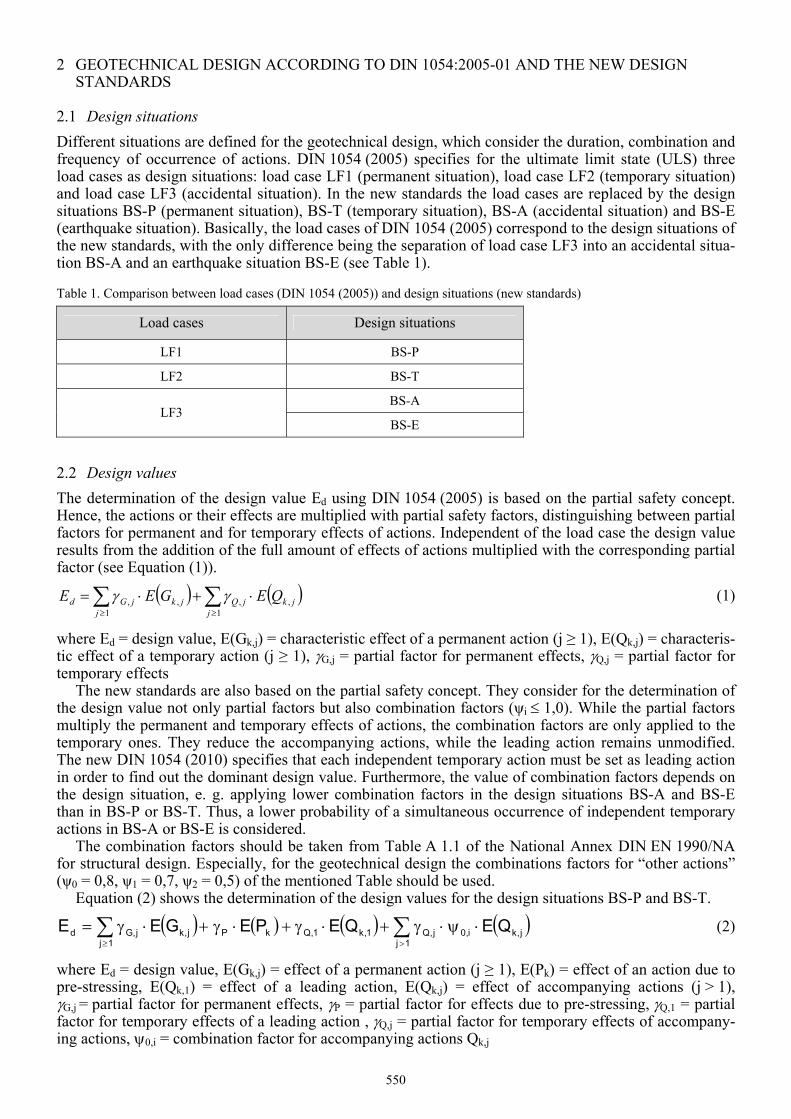
3.1 Sheet pile quay wall The sheet pile quay wall has been designed without and with consideration of combination factors using the Recommendations of the Committee for Waterfront Structures Harbours and Waterways EAU 2004. The design has been carried out against loads caused by soil self weight (Eah,g), container weight (Eah,Cont), operating crane (Eah,Cr), pore water pressure (W), and bollard pull (PPull) (see Figure 1). The earth pressure has been calculated considering a redistribution of the earth pressure according to EAU 2004.
The calculations have been carried out assuming a theoretical depth of 10 m, a groundwater level 4,4 m below ground surface, a variable channel water level depending on the load case and design situa-tion respectively and a bollard positioned 3,0 m below ground level. Only one soil layer was considered. Friction angles between 30,0° and 37,5° for cohesionless soils and between 22,5° and 27,5° for cohesive soils were chosen. The cohesion was set between 5 kN/m² to 20 kN/m².
Cr,V
Cr,H
PPull
50,0 kN/m²
168,9 kN/m
25,0 kN/m
57,1 kN/m
eah,g w eah,Cont
eah,Cr,V+H
Eah,gW
Eah,Cont
Eah,Cr
2,5
m
h = 10,0 m
3,0
m
hp
Figure 1. Loads and dimensions for the design of the sheet pile quay wall
551
The assumed structural system was a fully restrained, one-anchored sheet pile wall with a restraint degree of 100% in order to minimize deformations. The anchor was placed 2,5 m below ground surface (see Fig-ure 1). Depending on the anchor position and the construction method, backfilling or excavation, an earth pressure redistribution according to EAU 2004 was assumed. It was chosen backfilling, redistributing the earth pressure near the anchor in accordance with EAU 2004, Figure E 77-4, case 6.
When calculating the permanent situation (load case LF1 or design situation BS-P) loads caused by soil self weight, container weight, operating crane and pore water pressure were taken into account. For the temporary situation (load case LF2 or BS-T) as well as for the accidental situation (load case LF3 or BS-A) additional loads caused by a bollard pull and a scouring have been considered.
For all design situations embedment depth, anchor length and sheet pile section have been calculated. The final design value was the maximum value of all cases. The sheet pile section has been determined carrying out a verification against structural failure depending on the bending moment and the section modulus. The anchor length has been calculated verifying the stability for anchoring at the lower failure plane. The required embedment depth has been determined by equilibrium calculations showing that the resistance on the passive side is sufficient to prevent a soil failure. Furthermore, the safety against vertical failure of the embedded wall has been verified.
When designing with the new standards, each independent temporary action was set as leading action, applying the combination factors ψi to the remaining accompanying actions.
In order to indicate the ratio between temporary and permanent actions the ratio QTot/GTot has been de-termined taking into account the earth pressure from soil self weight (Eah,g), container weight (Eah,Cont) and operating crane (Eah,Cr) as well as pore water pressure (W) and a load caused by a bollard pull (PPull). Equation (3) shows the calculation of the ratio QTot/GTot.
g,ah
PullCr,ahCont,ah
Tot
Tot
EPWEE
GQ
(3)
The ratio QA/QTot indicates the ratio of the amount of reduced temporary actions (accompanying actions) to the total temporary actions. Equation (4) shows the calculation of the ratio QA/QTot for the load caused by container weight as leading action.
PullCr,ahCont,ah
PullCr,ah
Tot
A
PWEEPWE
(4)
3.2 Foundation of a production hall The foundation of a production hall has been designed without and with consideration of combination factors. In addition, a design with a double consideration of combination factors has been carried out. In this manner, it was intended to analyse an incorrect design caused by a false interpretation of the founda-tion loads. If the structural engineer delivers foundation loads already reduced with combination factors but without any specifications, the geotechnical engineer would apply again combination factors to the foundation loads, reducing them twice.
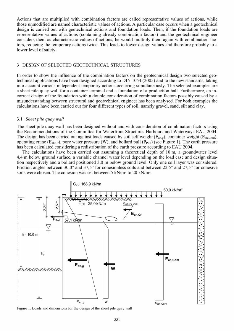
In this geotechnical example a square foundation has been dimensioned to resist loads caused by self weight (GD, GS and GF), wind (WH), snow (S) and operating cranes (Cr,v and Cr,h) with an assumed em-bedded depth of 0,8 m (see Figure 2). The calculations have been carried out for one soil layer, consider-ing friction angles between 30° and 37,5° for cohesionless soils and between 22,5° and 27,5° for cohesive soils. The cohesion was varied between 5 kN/m² and 20 kN/m² for drained conditions and between 20 kN/m² and 60 kN/m² for undrained conditions.
552
a = b
d = 0,8 m
7,0 m
1,0 m
0,5 mWH
GD
S
Cr,h
Cr,v
4,5 mGS
GF
Figure 2. Loads and dimensions for the design of the production hall foundation.
The required foundation width has been determinated for each limit state, verifying the safety against ground bearing failure, the safety against failure by sliding on the base and the allowed eccentricity.
When determining the design value for the permanent and temporary situations, loads caused by self weight, wind, snow and operating cranes were taken into account. The temporary situation differed from the permanent situation considering an excavation on one side of the foundation, assumed for repair works. For the accidental situation, an extreme horizontal operating crane load caused by the impact of the trolley on the damping device additional to the loads in the permanent or temporary situation has been considered.
Moreover, three combinations of actions have been defined in order to find out the most unfavourable load case for each limit state and design situation. Combination of actions 1 considered loads caused by wind and self weight of the construction, resulting in the lowest normal forces in conjunction with the re-spective maximal tangential forces on the base. Combination of actions 2 considered loads caused by wind, operating crane and self weight of the construction. With this combination of actions the maximum bending moments have been obtained. Combination of actions 3 took into account loads caused by wind, snow, operating crane and self weight of the construction. This combination led to the highest normal forces.
Furthermore, the calculations have been carried out for four calculation cases in order to analyse the influence of combination factors and the design approach of the new standards on the geotechnical de-sign. These are:
- Calculation case 1: foundation loads are characteristic values of actions, calculating without applica-tion of combination factors using DIN 1054 (2005).
- Calculation case 2: foundation loads are representative values of actions, calculating without applica-tion of combination factors using DIN 1054 (2005).
- Calculation case 3: foundation loads are characteristic values of actions, calculating with application of combination factors using the new DIN 1054 (2010).
- Calculation case 4: foundation loads are representative values of actions, calculating with application of combination factors using the new DIN 1054 (2010) (double consideration of combination fac-tors).
In the framework of the research project the ratios QTot/GTot and QA/QTot have been determinated consid-ering only the vertical foundation loads. The ratios QTot/GTot and QA/QTot have been calculated using Equations (5) and (6). Equation (6) shows the case when the load caused by operating crane is the leading action.
FSD
v,r
Tot
Tot
GGGSC
GQ (5)
553
SCSv,rTot
A
QQ (6)
4 RESULTS
In order to identify clearly the differences between a design according to DIN 1054 (2005) and one ac-cording to the new standards, the results have been represented in diagrams depending on the ratio QTot/GTot.
The required embedment depth and the required anchor length for the sheet pile wall have been nor-malised both with the theoretical depth h and with the required sheet pile length hp. The maximal calcu-lated bending moment has been normalised by the product of the active earth pressure from soil self weight (Eah,g) with h or hp. Five different ratios QTot/GTot have been calculated for each design value, one design value in accordance with DIN 1054 (2005) and up to four design values depending on the design situation and the amount of leading actions in accordance with the new standards.
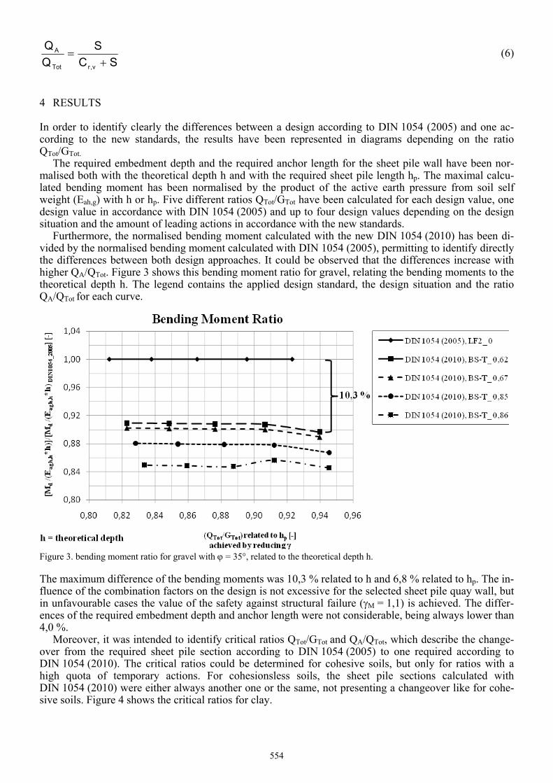
Furthermore, the normalised bending moment calculated with the new DIN 1054 (2010) has been di-vided by the normalised bending moment calculated with DIN 1054 (2005), permitting to identify directly the differences between both design approaches. It could be observed that the differences increase with higher QA/QTot. Figure 3 shows this bending moment ratio for gravel, relating the bending moments to the theoretical depth h. The legend contains the applied design standard, the design situation and the ratio QA/QTot for each curve.
Figure 3. bending moment ratio for gravel with = 35°, related to the theoretical depth h.
The maximum difference of the bending moments was 10,3 % related to h and 6,8 % related to hp. The in-fluence of the combination factors on the design is not excessive for the selected sheet pile quay wall, but in unfavourable cases the value of the safety against structural failure (M = 1,1) is achieved. The differ-ences of the required embedment depth and anchor length were not considerable, being always lower than 4,0 %.
Moreover, it was intended to identify critical ratios QTot/GTot and QA/QTot, which describe the change-over from the required sheet pile section according to DIN 1054 (2005) to one required according to DIN 1054 (2010). The critical ratios could be determined for cohesive soils, but only for ratios with a high quota of temporary actions. For cohesionsless soils, the sheet pile sections calculated with DIN 1054 (2010) were either always another one or the same, not presenting a changeover like for cohe-sive soils. Figure 4 shows the critical ratios for clay.
554
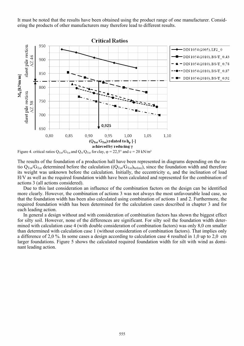
It must be noted that the results have been obtained using the product range of one manufacturer. Consid-ering the products of other manufacturers may therefore lead to different results.
Figure 4. critical ratios QTot/GTot and QA/QTot for clay, = 22,5° and c = 20 kN/m²
The results of the foundation of a production hall have been represented in diagrams depending on the ra-tio QTot/GTot determined before the calculation ((QTot/GTot)before), since the foundation width and therefore its weight was unknown before the calculation. Initially, the eccentricity ex and the inclination of load H/V as well as the required foundation width have been calculated and represented for the combination of actions 3 (all actions considered).
Due to this last consideration an influence of the combination factors on the design can be identified more clearly. However, the combination of actions 3 was not always the most unfavourable load case, so that the foundation width has been also calculated using combination of actions 1 and 2. Furthermore, the required foundation width has been determined for the calculation cases described in chapter 3 and for each leading action.
In general a design without and with consideration of combination factors has shown the biggest effect for silty soil. However, none of the differences are significant. For silty soil the foundation width deter-mined with calculation case 4 (with double consideration of combination factors) was only 8,0 cm smaller than determined with calculation case 1 (without consideration of combination factors). That implies only a difference of 2,0 %. In some cases a design according to calculation case 4 resulted in 1,0 up to 2,0 cm larger foundations. Figure 5 shows the calculated required foundation width for silt with wind as domi-nant leading action.
555
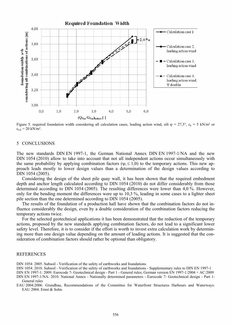
Figure 5. required foundation width considering all calculation cases, leading action wind, silt = 27,5°, ck = 5 kN/m² or cu,k = 20 kN/m².
5 CONCLUSIONS
The new standards DIN EN 1997-1, the German National Annex DIN EN 1997-1/NA and the new DIN 1054 (2010) allow to take into account that not all independent actions occur simultaneously with the same probability by applying combination factors (ψi 1,0) to the temporary actions. This new ap-proach leads mostly to lower design values than a determination of the design values according to DIN 1054 (2005).
Considering the design of the sheet pile quay wall, it has been shown that the required embedment depth and anchor length calculated according to DIN 1054 (2010) do not differ considerably from those determined according to DIN 1054 (2005). The resulting differences were lower than 4,0 %. However, only for the bending moment the differences were up to 10,3 %, leading in some cases to a lighter sheet pile section than the one determined according to DIN 1054 (2005).
The results of the foundation of a production hall have shown that the combination factors do not in-fluence considerably the design, even by a double consideration of the combination factors reducing the temporary actions twice.
For the selected geotechnical applications it has been demonstrated that the reduction of the temporary actions, proposed by the new standards applying combination factors, do not lead to a significant lower safety level. Therefore, it is to consider if the effort is worth to invest extra calculation work by determin-ing more than one design value depending on the amount of leading actions. It is suggested that the con-sideration of combination factors should rather be optional than obligatory.
REFERENCES
DIN 1054: 2005. Subsoil - Verification of the safety of earthworks and foundations DIN 1054: 2010. Subsoil - Verification of the safety of earthworks and foundations - Supplementary rules to DIN EN 1997-1 DIN EN 1997-1: 2009. Eurocode 7- Geotechnical design - Part 1 - General rules; German version EN 1997-1:2004 + AC:2009 DIN EN 1997-1/NA: 2010. National Annex - Nationally determined parameters - Eurocode 7- Geotechnical design - Part 1-
General rules EAU 2004:2006. Grundbau, Recommendations of the Committee for Waterfront Structures Harbours and Waterways:
EAU 2004. Ernst & Sohn.
556