Embed Size (px)
Citation preview
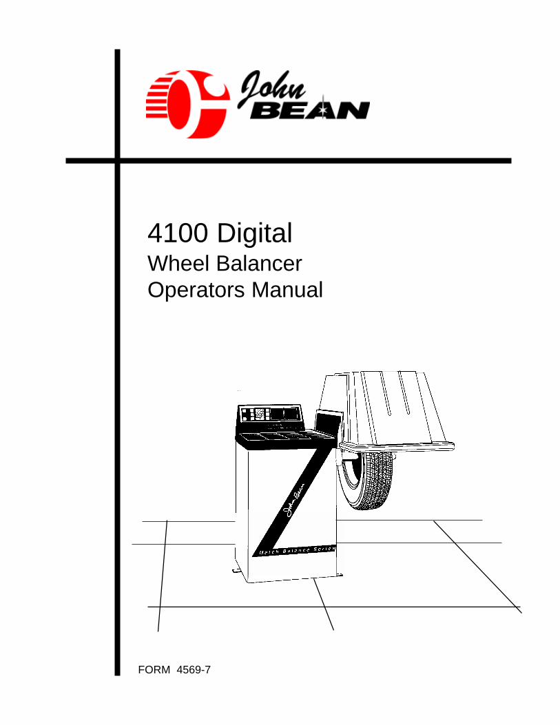
FORM 4569-7
4100 DigitalWheel BalancerOperators Manual
2
IMPORTANT SAFETY INSTRUCTIONS
When using this equipment, basic safety precautions should always be followed,including the following:
1. Read all instructions.
2. Do not operate equipment with a damaged power cord or if the equipment hasbeen damaged - until it has been examined by a qualified authorized servicetechnician.
3. If an extension cord is used, a cord with a current rating equal to or more thanthat of the machine should be used. Cords rated for less current than theequipment may overheat. Care should be taken to arrange the cord so that it isnot be tripped over or pulled.
4. Always unplug equipment from electrical outlet when not in use. Never use thecord to pull the plug from the outlet. Grasp plug and pull to disconnect.
5. To reduce the risk of fire, do not operate equipment in the vicinity of opencontainers of flammable liquids (gasoline).
6. Keep hair, loose fitting clothing, fingers and all parts of the body away frommoving parts.
7. Adequate ventilation should be provided when working on operating internalcombustion engines.
8. To reduce the risk of electric shock, do not use on wet surfaces or expose torain.
9. Do not hammer on or hit any part of the machine with weight pliers.
10. Do not disable the hood safety interlock system or bypass the intendedoperation.
11. Do not allow unauthorized personnel to operate the equipment.
12. Use only as described In this manual. Use only manufacturer’s recommendedattachments.
13. Always securely tighten the wing nut before spinning the shaft.
14. ALWAYS WEAR SAFETY GLASSES. Everyday eyeglasses only have impactresistant lenses, they are NOT safety glasses.
15. Do not raise wheel guard until wheel is completely stopped
SAVE THESE INSTRUCTIONS
3
TABLE OF CONTENTSPage
Introduction and Specifications 4
I Equipment/Accessories 5
II Installation 6
III Principles of Operation 7
IV Calibration 8
V Mounting 9
VI Balancing Std. Wheels 11
Weight Application Chart 12-13
Function Codes 14
Match Balancing 16-17
Calibration Check Procedure 18
Preventive Maintenance Tips 18
Vibration Complaint Diagnostics 19-20
4
TO THE PURCHASER
Congratulations! You have pur-chased one of the finest wheel bal-ancers built today. It will bring youmany years of dependable serviceand a rewarding return on your in-vestment. Please read this Operat-ing Manual carefully. It contains stepby step operating procedures thatwill enable you to make maximumuse of your balancer. The manualcontains information on calibrationand preventive maintenance tips.Your balancer incorporates the lat-est electronic technology and offersthese features:
Programmed Computer Balance:Operator actually programs the bal-ancing computer for wheel size, di-ameter, and location on the balanc-ing shaft (distance). Ability to pro-gram for specific wheel size permitsextreme accuracy.
Microprocessor Computer Con-trol:Finger tip data entry insures ease ofoperation. The unique keyboard andcomputer combination provide a vi-sual indication of each step per-formed for programming. Computerto operator feedback reduces op-erator error.
Automatic Single Spin:Operator closes wheel cover (if auto-spin model) or pushes SPIN button(early machines or one with auto-spin function disabled) and balancerstarts spinning, makes imbalancemeasurements, and stops automati-cally within seconds.
Precise Weight Amount and Lo-cation:Weight amount is accurate to 0.1 oz.(2.8gm). Weight angle resolution is1.4°. This provides precision wheelbalancing that virtually eliminates vi-bration complaints. Automatic cycleplus centering cone mounting meanswheel balancing is done accuratelythe first time.
Overhead Guard With Safety In-terlock: Guard swings overheadrequiring minimum floor space. Bal-ancer will not operate unless guardis safely in place over tire/wheel.
Static Balance:Built-in static feature enables staticbalancing only. No need to turn downspecial wheel balancing applications.
Special ALU Mode:Automatic data entry for hiddenweight placement on aluminumstyled wheels. Eliminates tape mea-surements for correct weight place-ment in many instances.
Special Wheel Capability:Adapters allow balancing of almostall wheels including specialty OEM,foreign cars, and aftermarket alloywheels without the need to use faceplates.
Dynamic Self-Calibration:Operator calibrates unit in a matterof seconds. Complete system iscalibrated under actual operatingconditions using calibration weightsupplied with the unit. Special adapt-ers, adjustment tools, and trainingare not necessary.
Match Balancing Capability:The John Bean computerized MatchBalance program can be used toperform diagnosis and/or correctionof problems resulting from rims andtires with runout and imbalance con-ditions.
Generous Weight Storage:17 weight storage bins are provided.Operator need not lose time andefficiency hunting for weights.
Drive Motor:Rated at 1/2HP - less strain andlonger motor life.
Specifications:
Accuracy: To 0.10 oz. (2.8gm)Digital Readout: ounces or gramsSpin: Automatic or manual
9 BALANCING MODESStatic or dynamic balance6 weight placement (Alum)modesMatch Balancing
- Single spin balance- Enclosed wheel guard with
safety interlock- Shaft Rotation Speed: 200 rpm- 14 revolutions for measurement- Microprocessor controlled- Operator self-calibration- Touch pad keyboard- Self-diagnostic capabilities- Digital display round off to .25 oz.
(5gms), non round-off to .05 oz. (1gm)
- 1/2 H.P. Induction motor- Shaft size: 1 9/16" diameter (40
mm)- Parameter memory up to 4 jobs
simultaneously- 20 weight pockets- Weight angle resolution: 1.4°- Digital display panel
Note: John Bean Company reservesthe right to incorporate changes indesigns or materials, affecting prod-uct improvements, without obliga-tion of incorporating same on equip-ment of prior manufacture.
Rim Width: 3-19" (76mm483mm)Rim Diameter: 3-24" (202mm10mm)Tire Diameter: up to 40" (1016mm)Tire Wt: up to 120lbs. (54kg)Footprint: 97"x 60” (2464mm
1524mm)Shipping Weight: 380 lbs. (173kg)Shipping Volume: 38.8 cu.ft. (1.1m3 )Power: 115volt 1 ph, 60 cycle
Manufactured in U.S.A.
5
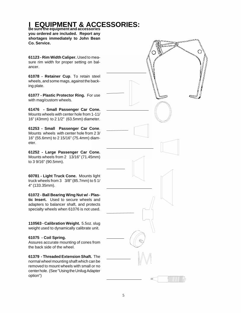
I EQUIPMENT & ACCESSORIES:Be sure the equipment and accessoriesyou ordered are included. Report anyshortages immediately to John BeanCo. Service.
61123 - Rim Width Caliper. Used to mea-sure rim width for proper setting on bal-ancer.
61078 - Retainer Cup. To retain steelwheels, and some mags, against the back-ing plate.
61077 - Plastic Protector Ring. For usewith mag/custom wheels.
61476 - Small Passenger Car Cone.Mounts wheels with center hole from 1-11/16" (43mm) to 2 1/2" (63.5mm) diameter.
61253 - Small Passenger Car Cone.Mounts wheels with center hole from 2 3/16" (55.6mm) to 2 15/16" (75.4mm) diam-eter.
61252 - Large Passenger Car Cone.Mounts wheels from 2 13/16" (71.45mm)to 3 9/16" (90.5mm).
60781 - Light Truck Cone. Mounts lighttruck wheels from 3 3/8" (85.7mm) to 5 1/4" (133.35mm).
61072 - Ball Bearing Wing Nut w/ - Plas-tic Insert. Used to secure wheels andadapters to balancer shaft, and protectsspecialty wheels when 61076 is not used.
110563 - Calibration Weight. 5.5oz. slugweight used to dynamically calibrate unit.
61075 - Coil Spring.Assures accurate mounting of cones fromthe back side of the wheel.
61379 - Threaded Extension Shaft. Thenormal wheel mounting shaft which can beremoved to mount wheels with small or nocenter hole. (See "Using the Unilug Adapteroption")

6
1- Position the Balancer
Floor Space.Locate your balancer where it canbe seen by your customers andwhere it will merchandise your com-puter wheel balancing capability.Allow sufficient room to mount wheelson one side and to remove accesso-ries from their mounting pegs on theother.
Unpacking the BalancerCut banding straps. Use caution toavoid sharp edges of banding. Liftcardboard box upward over balancertop. Cut banding from the hood guardand the accessory package. Setthese aside for now. Remove theskid mounting bolts from the bal-ancer base. Lift the balancer fromthe skid and place gently onto thefloor.
CAUTION! DO NOT LIFTBALANCER BY THESHAFT!
Site Preparation.Floor should be maintained levelwithin 1/4" (6mm) beneath the bal-ancer. Floor should be concrete andfree of heavy equipment vibrations.
1. Anchor to floor.The balancer should be anchored tothe floor, since large imbalances cancause vibration in the balancer thatmay make it necessary to spin morethan once.
a. Mark anchor holes either byplacing the balancer in the desiredlocation and marking through the tie-down holes or by using the dimen-sions shown on adjacent diagram.
b. Drill four 1/2"(12mm) diameterholes by 3" (76.2mm) minimum depthand install stud anchors through bal-ancer mounting holes and into con-crete holes. Tighten bolts.
II INSTALLATIONWALL
FOOTPRINTinches and mm
2. Install Wheel Guarda. Insert the wheel guardshaft into the support col-umn pivot tube.
b. Secure the hood shaftin place by tapping the 5/16" diameter roll pin intothe drilled hole of theguard pivot shaft.
c. After power is input tothe machine, check func-tion of the auto-spin fea-ture.
CHECK THE BALANCER TO BESURE IT MEETS YOUR VOLTAGESUPPLY. SEE THE IDENTIFICA-TION PLATE ON THE REAR OF THEBALANCER.
IMPORTANT: Consult your electri-cian for proper wire size and ground-ing if a service outlet is being installedfor the balancer. Avoid excessivelylong power cords since a voltage dropcan occur and supply the balancerwith less than adequate voltage. Ex-tension cords should not be longerthan 20 feet (6m).
ROLL PIN
PIVOT AND SHAFT
WHEEL GUARD

7
Wheel Diameter button. Push to dis-play or enter the wheel diameter asread from the side wall of the tire. Usethe numbered keyboard to enter thewheel diameter parameter.
Wheel Width button. Push button todisplay or enter the wheel width, fol-lowed by a keyboard entry of the tire'srim measured width.
Wheel Distance button. Push thisbutton to display or enter the wheel'sdistance from the balancer measuredby the distance gauge. Enter the num-ber using the numbered keyboard.
Left Hand Weight Amount Window.Indicates the weight imbalance of theleft or inside plane of the tire and wheel.
Note: If the STOP but-ton is pressed, followedby a wheel cover clo-sure( raise & lower), thedisplays will show a se-ries of scanning dashes.This shows the balanceris still in use but thatthere is no reading to bedisplayed. Normal dis-play will return upon acompleted spin cycle.
Right Hand WeightAmount Window. In-dicates the weight im-balance of the right oroutside plane of the tireand wheel.
Left hand Position Win-dow. Indicates the left orinside plane weight location.A reading of 0 indicates theweight be placed at top deadcenter of the wheel.
Numbered Keyboard. Used toenter wheel parameters, andfunction codes.
"F" button. Allows the en-try of function codes. Func-tion codes are used for cus-tomizing, calibrating, and di-agnosing the balancer.
Spin (Green) button.Used to initiate spincycle and functioncodes.
Static - 2 Plane button.Balancer normally in 2plane mode. Press Static -2 plane button for staticmode. Mode of operationchanges (toggles) eachtime button is pressed.
Alloy Mode button.Changes weight place-ment mode for specialtywheels and hidden weightbalancing.
Stop (Red) button. Pushanytime to interrupt auto-matic cycle. Wheel will stopspinning.
Left hand Position Window. In-dicates the left or inside planeweight location. A reading of 0 indi-cates the weight be placed at topdead center of the wheel.
Control Panel
STADYN
III PRINCIPLES OF OPERATIONWhen the distance from the ma-chine to the wheel is measured andentered into the computer, we aretelling the computer where the “in-ner” plane is located on the balancershaft. When the rim width is mea-sured and entered into the com-puter, we are telling the computer toadd this measurement to the dis-tance gauge data so that the com-puter knows where the “outer” planeis located on the shaft. Program-ming in the rim diameter tells thecomputer how far away the correc-
This machine is a two-plane micro-processor-based electronic bal-ancer. “Two-plane” means that anyimbalance in the wheel -- whetherstatic or dynamic -- can be correctedthrough proper placement of weights.These two planes must naturally beat the inner and outer faces of thewheel, since these are the normalplaces where corrective weights areapplied. Under special circum-stances, the location of these planescan be altered as long as the bal-ancer is properly programed.
tive weights will be applied from thecenter of the wheel.
When a wheel is spun, the computerdetects any imbalance on the shaft.Weight amount readouts, left andright, for inner and outer planes,indicate the amount required to cor-rect each plane. Weight position dis-plays indicate where weights mustbe applied. The balancer detectsshaft RPM and does not begin totake these measurements until thewheel has reached proper speed.

8
Step TwoBare Shaft
CalibrationWeight
IV Calibration
1. Press F1 and SPIN
2. The display will read "CAL Slu". Attachthe round calibration weight in the threadedhole from the outer edge. See Figure 1
3. Press SPIN again or lower the WheelGuard to initiate the balancer spin cycle.The shaft will turn for about 15 seconds.
4. The display will then change to "CAL 0".Remove calibration weight and Press SPINor lower the wheel guard to perform secondstep of calibration. See Figure 2
5. After another 15 second spin the displaywill read "CAL Good" to indicate a goodcalibration. Please secure the calibrationweight in its proper place for safe keeping.
Figure 1
Figure 2
CHECK SPIN: To verify a calibration, place the calibration weight onto the bareshaft in its threaded hole. With the default wheel parameters, lower the hood tospin. When braked, the display should read approximately 5.50 ozs on the left sideand 0.00 ozs on the right. To make sure default parameters are loaded, simply turnthe machine off, then back on.
NOTE: If any step is performed incorrectly or out of sequence, you may have adisplay that reads "SHAFT UNB"* or "CAL ER"*. If so, repeat the calibrationprocedure. If the display "SHAFT UNB" appears when the procedure is correct,then run a test spin with the calibration weight installed. If its weight is 5.5oz., thecalibration is acceptable. If the display "CAL ER" appears the second time, servicemay be required.
NOTE: If "CAL ER" appears on the display during a normal wheel balance routine,the balancer must be calibrated before proceeding.
* Calibration Error is represented by a display of "CAL ER"* Acceleration Error is displayed with "ACL ER"* Shaft Unbalanced is displayed as "SFT UNB"
5.50 0.00

9
V. WHEEL MOUNTINGStandard Wheels
Nearly all standard wheels and manyalloy wheels have accurately machinedcenter holes, and they should bemounted with center cones. Accuratebalancing depends on accurate mount-ing of the wheel and correct seating ofthe cone in the pilot hole to insure thatthe wheel is centered on the shaft.
Mount the wheel as shown at right:
1. Mount coil spring inside backing plate.2. Mount proper cone against spring.3. Mount wheel on shaft in the same manner as you would on the car.4. Mount retainer cup against outside of wheel5. Tighten wing nut securely with both hands.
NOTE: Some wheels not center centricmay require the use of an optional lugadapter plate.* An adapter plate allowsa wheel to be mounted using the lugholes as a center reference.
* Spring, cone, retainer cup, and wingnut may not be needed if adapter plateis used to mount wheel to balancershaft.
Failure to tighten wing nut se-curely may result in seriouspersonal injury.
Warning
Proper Size Cone
Coil Spring
Shaft
Retainer Cup
Wing Nut
Assembled Detail
Check ListObserve Before Balancing Wheel
1. Check for proper air pressure.If not correct, inflate to correctpressure.
2. Check for any foreign mate-rial inside tire. If present, re-move before balancing tire.
WATER IS FOREIGN MA-TERIAL.
3. Be sure the tire and wheelare free of excessive dirtand large stones.
4. Remove old weights -- oldweights may be impropervalue or in wrong location.
5. Be sure that the right sizetire has been mounted on thewheel.
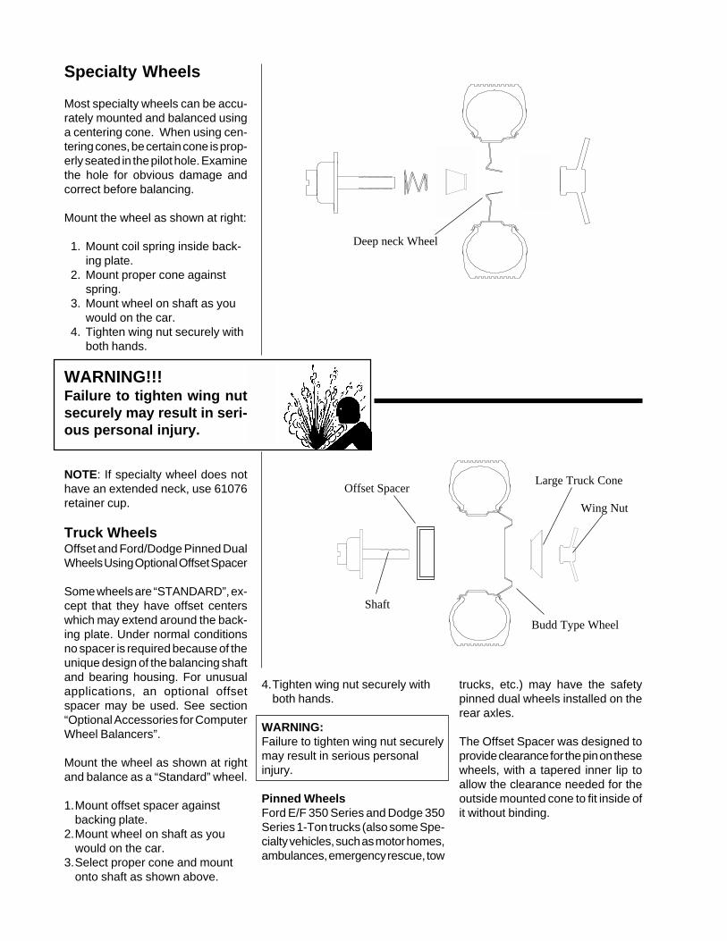
Deep neck Wheel
Specialty Wheels
Most specialty wheels can be accu-rately mounted and balanced usinga centering cone. When using cen-tering cones, be certain cone is prop-erly seated in the pilot hole. Examinethe hole for obvious damage andcorrect before balancing.
Mount the wheel as shown at right:
1. Mount coil spring inside back-ing plate.
2. Mount proper cone againstspring.
3. Mount wheel on shaft as youwould on the car.
4. Tighten wing nut securely withboth hands.
WARNING!!!Failure to tighten wing nutsecurely may result in seri-ous personal injury.
NOTE: If specialty wheel does nothave an extended neck, use 61076retainer cup.
Truck WheelsOffset and Ford/Dodge Pinned DualWheels Using Optional Offset Spacer
Some wheels are “STANDARD”, ex-cept that they have offset centerswhich may extend around the back-ing plate. Under normal conditionsno spacer is required because of theunique design of the balancing shaftand bearing housing. For unusualapplications, an optional offsetspacer may be used. See section“Optional Accessories for ComputerWheel Balancers”.
Mount the wheel as shown at rightand balance as a “Standard” wheel.
1.Mount offset spacer againstbacking plate.
2.Mount wheel on shaft as youwould on the car.
3.Select proper cone and mountonto shaft as shown above.
Budd Type Wheel
Wing Nut
Large Truck ConeOffset Spacer
Shaft
trucks, etc.) may have the safetypinned dual wheels installed on therear axles.
The Offset Spacer was designed toprovide clearance for the pin on thesewheels, with a tapered inner lip toallow the clearance needed for theoutside mounted cone to fit inside ofit without binding.
4.Tighten wing nut securely withboth hands.
WARNING:Failure to tighten wing nut securelymay result in serious personalinjury.
Pinned WheelsFord E/F 350 Series and Dodge 350Series 1-Ton trucks (also some Spe-cialty vehicles, such as motor homes,ambulances, emergency rescue, tow
11
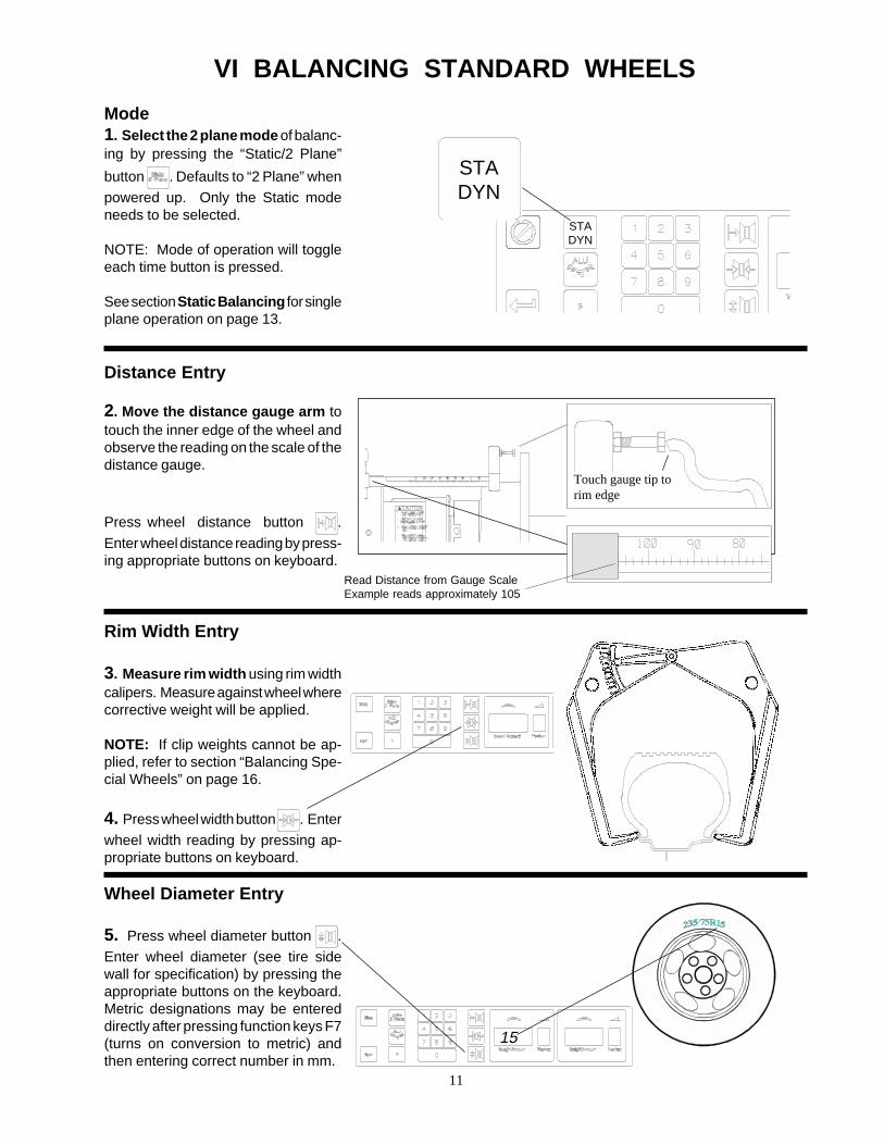
VI BALANCING STANDARD WHEELS
Touch gauge tip torim edge
Read Distance from Gauge ScaleExample reads approximately 105
15
Mode1. Select the 2 plane mode of balanc-ing by pressing the “Static/2 Plane”
button . Defaults to “2 Plane” when
powered up. Only the Static modeneeds to be selected.
NOTE: Mode of operation will toggleeach time button is pressed.
See section Static Balancing for singleplane operation on page 13.
Distance Entry
2. Move the distance gauge arm totouch the inner edge of the wheel andobserve the reading on the scale of thedistance gauge.
Press wheel distance button .
Enter wheel distance reading by press-ing appropriate buttons on keyboard.
Rim Width Entry
3. Measure rim width using rim widthcalipers. Measure against wheel wherecorrective weight will be applied.
NOTE: If clip weights cannot be ap-plied, refer to section “Balancing Spe-cial Wheels” on page 16.
4. Press wheel width button . Enter
wheel width reading by pressing ap-propriate buttons on keyboard.
Wheel Diameter Entry
5. Press wheel diameter button .
Enter wheel diameter (see tire sidewall for specification) by pressing theappropriate buttons on the keyboard.Metric designations may be entereddirectly after pressing function keys F7(turns on conversion to metric) andthen entering correct number in mm.
STADYN
STADYN

12
CHECK SPINLower the wheel guard. After spin is completed, weightamount windows should display zero (0.00), indicatingthat balance has been achieved.
VII. CHECK FOR PROPER WEIGHT APPLI-CATION
NOTE: On rare occasions, more than one spin may berequired to balance the wheel. If so, check the followingsteps:
Weight ErrorIf weight amount windows do not read zero (0.00) andshow that a second weight is required at the same oropposite location as the first weight, you have a weighterror. You can replace the first weight with the correctamount or apply the second weight where it calls for it.
Position (Location) ErrorIf weight amount windows do not read zero (0.00) andyou find that a second weight is required at an angle(less than 180°) to the first weight, you have a positionerror. Move the first weight toward the position that itcalls for, or add a second weight at the proper position.
All of the above methods will produce a perfect balanceif done properly.
BALANCING SPECIAL/ALLOY WHEELS(Adhesive Weights)
If standard clip weights are to be used, balance as a“Standard” wheel.
The Alloy Mode or Aluminum mode of operation isused when some specialty wheels are to be balanced,or when adhesive weights are required, i.e., hiddenweight method. The ALU mode is entered by pressingthe ALU button followed by the desired mode locationnumber.
IF ADHESIVE WEIGHTS OR TAPE WEIGHTS MUSTBE USED, FOLLOW THESE INSTRUCTIONS:
SPINNING THE WHEELLower the wheel guard to activate spin function. Thebalancer will automatically spin the wheel and stop itself.(NOTE: F6 switches between auto-spin and non-auto-spin.) Imbalance reading will be displayed and stored aslong as power is applied to the balancer.
After wheel has come to a complete stop, raise thewheel guard.
WARNING
Balancer will not operate unlesswheel guard is in lowered position.Do not raise wheel guard until wheelhas come to a complete stop.
WARNING
Do not raise wheel guard until wheelis completely stopped. Failure todo so may result in serious per-sonal injury.
PLACING THE WEIGHTStarting with either left or right of the wheel (inner orouter plane), rotate the wheel until a zero (0) appears inthe appropriate weight position window.
Apply weight displayed in the appropriate weight amountwindow at top dead center (12 o’clock) while weightposition window displays zero (0). Repeat for the otherside.
TOP DEAD CENTER
WARNINGBe sure weights are properly applied and are secure onthe wheel. Failure to do so may cause weights to comeloose resulting in serious personal injury.
13
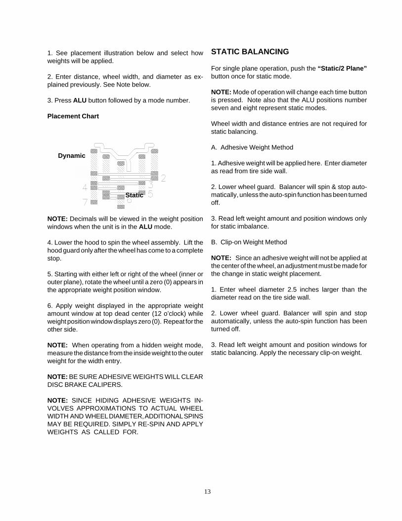
1. See placement illustration below and select howweights will be applied.
2. Enter distance, wheel width, and diameter as ex-plained previously. See Note below.
3. Press ALU button followed by a mode number.
Placement Chart
Dynamic
Static
NOTE: Decimals will be viewed in the weight positionwindows when the unit is in the ALU mode.
4. Lower the hood to spin the wheel assembly. Lift thehood guard only after the wheel has come to a completestop.
5. Starting with either left or right of the wheel (inner orouter plane), rotate the wheel until a zero (0) appears inthe appropriate weight position window.
6. Apply weight displayed in the appropriate weightamount window at top dead center (12 o’clock) whileweight position window displays zero (0). Repeat for theother side.
NOTE: When operating from a hidden weight mode,measure the distance from the inside weight to the outerweight for the width entry.
NOTE: BE SURE ADHESIVE WEIGHTS WILL CLEARDISC BRAKE CALIPERS.
NOTE: SINCE HIDING ADHESIVE WEIGHTS IN-VOLVES APPROXIMATIONS TO ACTUAL WHEELWIDTH AND WHEEL DIAMETER, ADDITIONAL SPINSMAY BE REQUIRED. SIMPLY RE-SPIN AND APPLYWEIGHTS AS CALLED FOR.
STATIC BALANCING
For single plane operation, push the “Static/2 Plane”button once for static mode.
NOTE: Mode of operation will change each time buttonis pressed. Note also that the ALU positions numberseven and eight represent static modes.
Wheel width and distance entries are not required forstatic balancing.
A. Adhesive Weight Method
1. Adhesive weight will be applied here. Enter diameteras read from tire side wall.
2. Lower wheel guard. Balancer will spin & stop auto-matically, unless the auto-spin function has been turnedoff.
3. Read left weight amount and position windows onlyfor static imbalance.
B. Clip-on Weight Method
NOTE: Since an adhesive weight will not be applied atthe center of the wheel, an adjustment must be made forthe change in static weight placement.
1. Enter wheel diameter 2.5 inches larger than thediameter read on the tire side wall.
2. Lower wheel guard. Balancer will spin and stopautomatically, unless the auto-spin function has beenturned off.
3. Read left weight amount and position windows forstatic balancing. Apply the necessary clip-on weight.
14
FUNCTION or "F" CODES
The 4100 Series Wheel Balancers utilize “F” (function)codes for operator convenience and service diagnos-tics. Some of the “F” codes are listed on this andfollowing page(s). If any of the below functions are notcorrect, consult your John Bean Field Service Repre-sentative.
F1 CalibrationThe 4100 Series was designed to be calibrated by theoperator. It automatically adjusts itself to read accurateweight amount. See page 8 for calibration detail.
NOTE: Calibration can be performed at any time.
NOTE: To cancel any F code sequence, press the stopbutton.
F2 Round-offThe 4100 balancer rounds off weight imbalances to thenearest 0.25oz. (5gr.) increments. This mode of opera-tion is automatically used (default) when the machine isturned on.
F3 Non-Round-offThe balancer may be operated in the non-Round-offmode to display weight imbalance in .05 oz. or 1 gmincrements.
F4 OuncesThe domestic model balancer displays weight imbal-ances in ounces, while the export models display weightin grams. F4 and F5 below can be used to switch fromounces to grams and back again if desired.
F5 GramsDomestic units display weights in ounces. To display ingrams enter F5.
F6 Auto-spinThe balancer can be switched to spin automaticallywhen the hood guard is lowered. If autospin is notdesired enter F6 again to switch off.
F7 ConvertThis code allows the direct entry of millimeters for thewheel diameter found on some vehicles (i.e. 390mm).The display will read "CON ON".
NOTE: To return to inches, simply reenter F7. Thedisplay should read "CON OFF".
F8 Dead Zone RoundoffMeasurement sensitivity of the weight imbalance in therange from 0 to 0.50oz can be changed from thekeyboard. This should normally be in the off mode.
If dr OFF appears, the machine will round off as follows:Imbalance of 0.125oz or below will round off tozero (0).
Imbalance greater than 0.125oz and less than0.375oz will round off to 0.25oz.
If dr ON appears, the machine will round off as follows:Imbalance of 0.30oz or below will round off tozero (0).
Imbalance greater than 0.30 and less than 0.35will round off to 0.25.
NOTE:TURNING THE POWER OFF AND ON WILL NOTCHANGE YOUR SELECTION.
Dead zone should be in the OFF mode for the majorityof operations.
F90 Computerized Match Balance ProcedureThe Match Balance feature allows a wheel and tire to be"Matched" to one another for optimum performance andminimum correcting weight placement. If a wheel is notcenter centric or has a heavy spot on one side, pressingF90 will prompt the machine to look for the heavy sideof the tire and place it opposite the wheel heavy side tohelp offset imbalance. This will not only minimize weightamount placement but also helps smooth out a ride.
F80 Series (Storage) CodesThis feature allows the operator to store common usedwheel parameters for later recall. This a time savingfeature especially useful in high volume shops. Seefollowing page for instructions.
15
WHEEL PARAMETER STORAGE
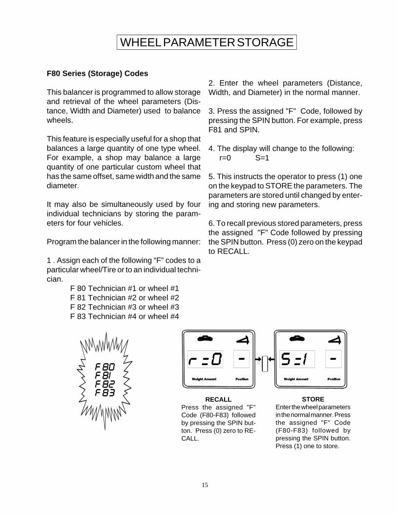
F80 Series (Storage) Codes
This balancer is programmed to allow storageand retrieval of the wheel parameters (Dis-tance, Width and Diameter) used to balancewheels.
This feature is especially useful for a shop thatbalances a large quantity of one type wheel.For example, a shop may balance a largequantity of one particular custom wheel thathas the same offset, same width and the samediameter.
It may also be simultaneously used by fourindividual technicians by storing the param-eters for four vehicles.
Program the balancer in the following manner:
1 . Assign each of the following “F” codes to aparticular wheel/Tire or to an individual techni-cian.
F 80 Technician #1 or wheel #1F 81 Technician #2 or wheel #2F 82 Technician #3 or wheel #3F 83 Technician #4 or wheel #4
2. Enter the wheel parameters (Distance,Width, and Diameter) in the normal manner.
3. Press the assigned "F" Code, followed bypressing the SPIN button. For example, pressF81 and SPIN.
4. The display will change to the following:r=0 S=1
5. This instructs the operator to press (1) oneon the keypad to STORE the parameters. Theparameters are stored until changed by enter-ing and storing new parameters.
6. To recall previous stored parameters, pressthe assigned "F" Code followed by pressingthe SPIN button. Press (0) zero on the keypadto RECALL.
STOREEnter the wheel parametersin the normal manner. Pressthe assigned "F" Code(F80-F83) followed bypressing the SPIN button.Press (1) one to store.
RECALLPress the assigned "F"Code (F80-F83) followedby pressing the SPIN but-ton. Press (0) zero to RE-CALL.
16
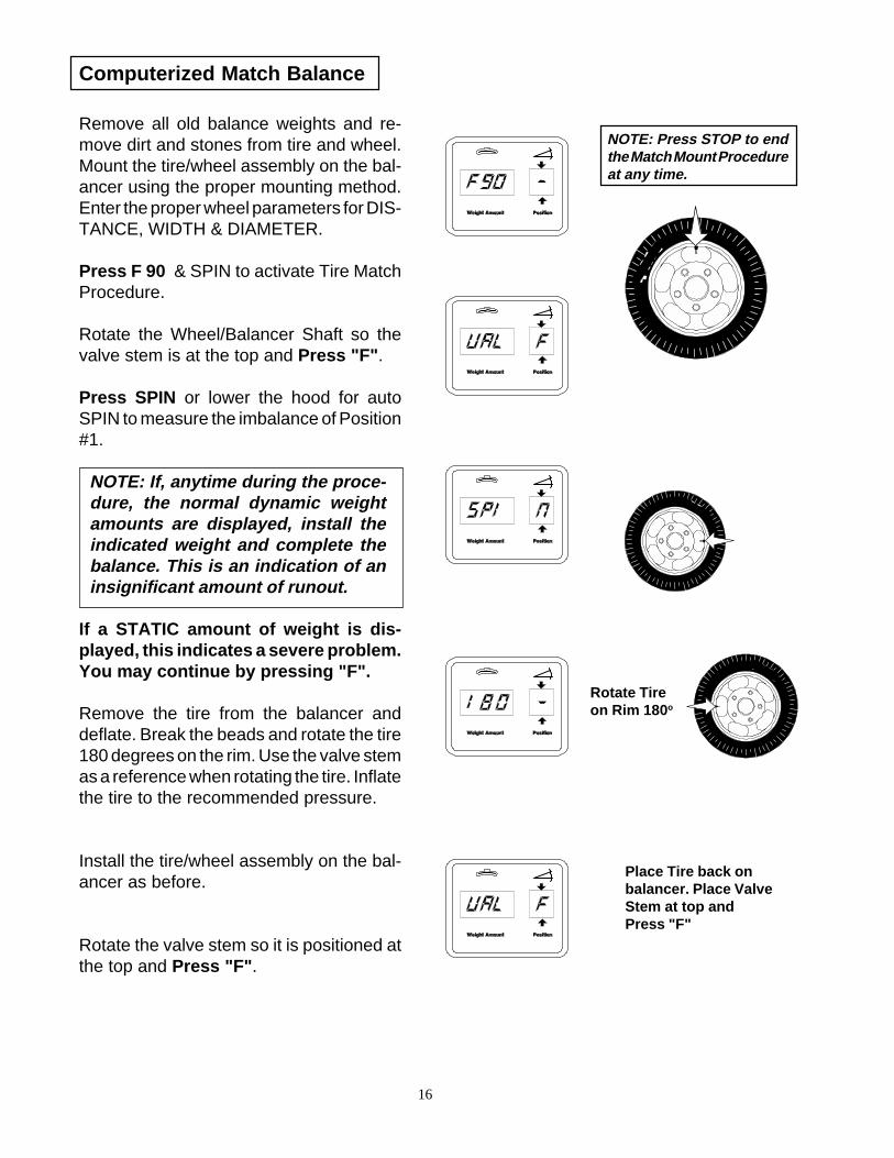
Computerized Match Balance
Remove all old balance weights and re-move dirt and stones from tire and wheel.Mount the tire/wheel assembly on the bal-ancer using the proper mounting method.Enter the proper wheel parameters for DIS-TANCE, WIDTH & DIAMETER.
Press F 90 & SPIN to activate Tire MatchProcedure.
Rotate the Wheel/Balancer Shaft so thevalve stem is at the top and Press "F".
Press SPIN or lower the hood for autoSPIN to measure the imbalance of Position#1.
NOTE: If, anytime during the proce-dure, the normal dynamic weightamounts are displayed, install theindicated weight and complete thebalance. This is an indication of aninsignificant amount of runout.
If a STATIC amount of weight is dis-played, this indicates a severe problem.You may continue by pressing "F".
Remove the tire from the balancer anddeflate. Break the beads and rotate the tire180 degrees on the rim. Use the valve stemas a reference when rotating the tire. Inflatethe tire to the recommended pressure.
Install the tire/wheel assembly on the bal-ancer as before.
Rotate the valve stem so it is positioned atthe top and Press "F".
NOTE: Press STOP to endthe Match Mount Procedureat any time.
Place Tire back onbalancer. Place ValveStem at top andPress "F"
Rotate Tireon Rim 180o
17
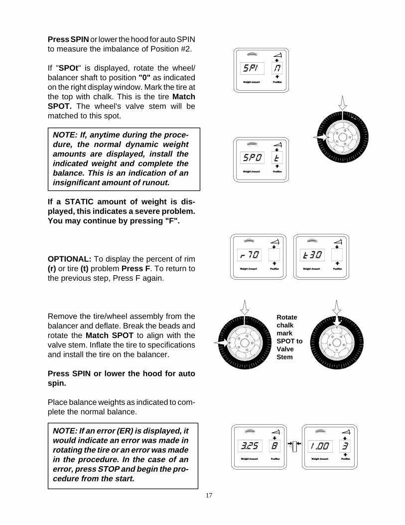
Press SPIN or lower the hood for auto SPINto measure the imbalance of Position #2.
If "SPOt" is displayed, rotate the wheel/balancer shaft to position "0" as indicatedon the right display window. Mark the tire atthe top with chalk. This is the tire MatchSPOT. The wheel's valve stem will bematched to this spot.
NOTE: If, anytime during the proce-dure, the normal dynamic weightamounts are displayed, install theindicated weight and complete thebalance. This is an indication of aninsignificant amount of runout.
If a STATIC amount of weight is dis-played, this indicates a severe problem.You may continue by pressing "F".
OPTIONAL: To display the percent of rim(r) or tire (t) problem Press F. To return tothe previous step, Press F again.
Remove the tire/wheel assembly from thebalancer and deflate. Break the beads androtate the Match SPOT to align with thevalve stem. Inflate the tire to specificationsand install the tire on the balancer.
Press SPIN or lower the hood for autospin.
Place balance weights as indicated to com-plete the normal balance.
NOTE: If an error (ER) is displayed, itwould indicate an error was made inrotating the tire or an error was madein the procedure. In the case of anerror, press STOP and begin the pro-cedure from the start.
RotatechalkmarkSPOT toValveStem
18
Calibration Check Procedure
This procedure can be performed by anyone and quicklychecks that the balancer is properly calibrated. If any ofthe checks below are not correct, consult with a JohnBean Company Service Representative.
1. Calibrate unit following procedure outlined under thesection headed “Function Codes”.
2. Mount a wheel and balance to zero. Insure that unithas been properly programmed for wheel distance,width, and diameter.
3. Select F3 (non-Round-off mode of operation) and finebalance to zero, within 0.1 ounces (4gr.).
4. Apply 3oz. (85gr.) test weight to inner plane. Spin andcheck that right hand weight amount reads 0 within0.1oz. (4gr.). This checks plane separation.
5. With test weight still on inner plane, check that lefthand amount meter reads 3oz. (85gr.) within 0.1oz.(4gr.) (weight amount - inside plane).
6. Stop and rotate the wheel so that the 3oz. (85gr.) testweight is at bottom dead center (6 o’clock). Check thatleft hand position is zero (0) (location - inside plane).
7. Move test weight to outer plane. Spin and check thatleft hand amount reads 0 within 0.1oz. (4gr.) (planeseparation).
8. With test weights still on the outer place, check thatright hand amount reads 3oz. (85gr.) within 0.1oz. (4gr.)(weight amount - outside plane).
9. Stop and rotate the wheel so that the test weight is atbottom dead center (6 o’clock). Check that right handposition is zero (0) (location - outside plane).
Preventive Maintenance Tips
The 4100 Balancer has been designed for many yearsof trouble-free operation. However, it is a precisionmachine and should be used with care. We recommendattention to the following points for maximum use andbenefit from the equipment.
1. Control Panel: Clean periodically with a non-solvent, nonabrasive household cleaner. Do Not usebrake cleaner or carburetor cleaner.
2. Balancer Shaft: Avoid dropping wheels heavily onthe shaft, because doing so can cause nicks and affectmounting accuracy. Apply a light coat of 20 or 30 weightmachine oil to the shaft for rust prevention. Wipe offexcess and keep shaft clean. DO NOT use excessivegrease on shaft -- doing so may allow accumulation ofgrit and debris.
3. Mounting Adapters: Keep adapters clean. Toprevent rust, apply a light coat of machine oil and wipeoff excess. Do not use grease on adapters. Do not useadapters for purposes other than mounting wheels --nicks or cuts in the adapters can cause mounting errors.
4. Overhead Hood Guard: Periodically, apply a lightcoat of grease to the overhead guard support rod toprevent squeaking.
5. Impact Wrenches: Do not use impact wrencheswhen mounting wheels on the balancer adapters. Use ofimpact wrenches can cause adapters to become overtightened, possibly damaging the adapters and/or mount-ing bolts. Use only the T-handled wrench available as anoption.
19
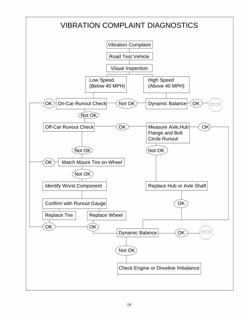
VIBRATION COMPLAINT DIAGNOSTICS
Vibration Complaint
Road Test Vehicle
Visual Inspection
Low Speed High Speed(Below 40 MPH) (Above 40 MPH)
OK On-Car Runout Check Not OK Dynamic Balance OK
Not OK
Off-Car Runout Check OK Measure Axle,Hub OKFlange and BoltCircle Runout
Not OK Not OK
OK Match Mount Tire on Wheel
Not OK
Identify Worst Component Replace Hub or Axle Shaft
Confirm with Runout Gauge OK
Replace Tire Replace Wheel
OK OKDynamic Balance OK
Not OK
Check Engine or Driveline Imbalance
20
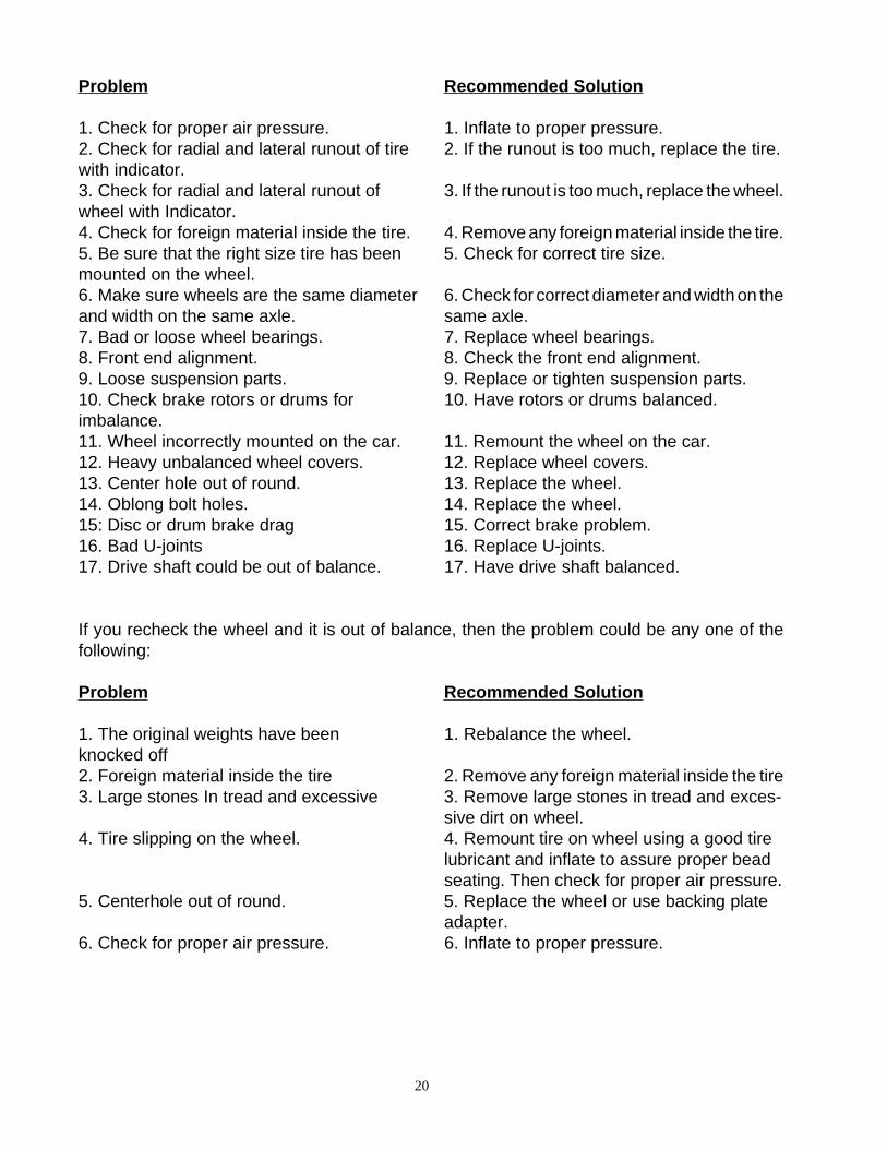
Problem Recommended Solution
1. Check for proper air pressure. 1. Inflate to proper pressure.2. Check for radial and lateral runout of tire 2. If the runout is too much, replace the tire.with indicator.3. Check for radial and lateral runout of 3. If the runout is too much, replace the wheel.wheel with Indicator.4. Check for foreign material inside the tire. 4. Remove any foreign material inside the tire.5. Be sure that the right size tire has been 5. Check for correct tire size.mounted on the wheel.6. Make sure wheels are the same diameter 6. Check for correct diameter and width on theand width on the same axle. same axle.7. Bad or loose wheel bearings. 7. Replace wheel bearings.8. Front end alignment. 8. Check the front end alignment.9. Loose suspension parts. 9. Replace or tighten suspension parts.10. Check brake rotors or drums for 10. Have rotors or drums balanced.imbalance.11. Wheel incorrectly mounted on the car. 11. Remount the wheel on the car.12. Heavy unbalanced wheel covers. 12. Replace wheel covers.13. Center hole out of round. 13. Replace the wheel.14. Oblong bolt holes. 14. Replace the wheel.15: Disc or drum brake drag 15. Correct brake problem.16. Bad U-joints 16. Replace U-joints.17. Drive shaft could be out of balance. 17. Have drive shaft balanced.
If you recheck the wheel and it is out of balance, then the problem could be any one of thefollowing:
Problem Recommended Solution
1. The original weights have been 1. Rebalance the wheel.knocked off2. Foreign material inside the tire 2. Remove any foreign material inside the tire3. Large stones In tread and excessive 3. Remove large stones in tread and exces-
sive dirt on wheel.4. Tire slipping on the wheel. 4. Remount tire on wheel using a good tire
lubricant and inflate to assure proper beadseating. Then check for proper air pressure.
5. Centerhole out of round. 5. Replace the wheel or use backing plateadapter.
6. Check for proper air pressure. 6. Inflate to proper pressure.

Blank Page
Notice: The information contained in this document is subject to change without notice. John Beanmakes no warranty with regard to this material. John Bean shall not be liable for errors containedherein or for incidental consequential damages in connection with furnishings, performance, or use ofthis material.
This document contains proprietary information which is protected by copyright and patents. All rightsare reserved. No part of this document may be photocopied, reproduced, or translated without priorwritten consent of John Bean.
are registered trademarks of Snap-on Technologies
Form 4569-7...03/12/01...wdc Printed in the USA
USAJohn Bean309 Exchange AvenueConway, Arkansas 72032Tel.: (800) 362-8326 or (501) 450-1500Fax: (501) 450-1585
FRANCEJohn BeanSnap-On Equipment FranceZ.A. Du Vert Galant15, rue de la GuivernoneBP 717595310 Saint Ouen L’AumoneTel: (33) 1-3448-5878Fax: (33) 1-3448-5879
UNITED KINGDOMSnap-On Equipment Ltd.John Bean Equipment GroupOld Medow RoadKings LynnNorforkPE30 4WJ
CANADAJohn Bean6500 Millcreek DriveMississauga, OntarioCanada L5N 2W6Tel: (905) 814-0114Fax: (905) 814-0110
GERMANYJohn Bean Auto Service GerateDivision to Sun Electric Deutschland GMbHGewerbepark SinnD-35764 Sinn Herborner Str. 7-9Tel: (49) 2772-9404-0Fax: (49) 2772-94042-23
LATIN AMERICASnap-on Tools International, Ltd.2801 80th StreetKenosha, WI 53143Tel: (262) 656-5003Fax: (414) 656-1403