Embed Size (px)
Citation preview

4.1
Topic 4
PROCESS MODELLING USING DATA FLOW DIAGRAMS;
DETAILED PROCESS DEFINITIONS; THE DATA DICTIONAARY
IMS9001 - Systems Analysis and Design
4.2
Logical and physical DFDs
Data flow diagrams may focus on either:
the “physical” view of the system’s processing
OR the “logical” view of the system’s
processing

4.3
Physical DFDs
represent a particular way of implementing the processes and data in a system
they are technology dependent they show how the processing takes
place and how the data is implemented

4.4
Logical DFDs
represent what a system must do regardless of how it is implemented
they are technology independent they show what processing, data
movements and data storage must occur in a system
they show the essential aspects of a system
4.5
Using Logical and Physical DFDs
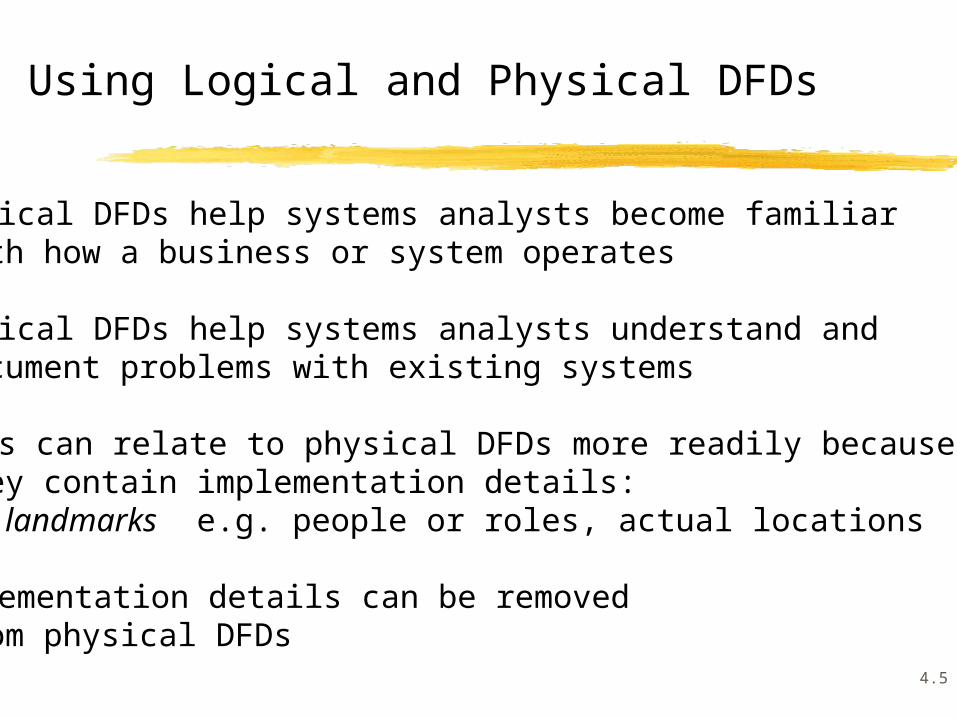
physical DFDs help systems analysts become familiar with how a business or system operates
physical DFDs help systems analysts understand and document problems with existing systems
users can relate to physical DFDs more readily because they contain implementation details:
landmarks e.g. people or roles, actual locations
implementation details can be removed from physical DFDs

4.6
use names for data flows and data stores which indicate their content, not their physical form or location
use names for processes that indicate what, not how
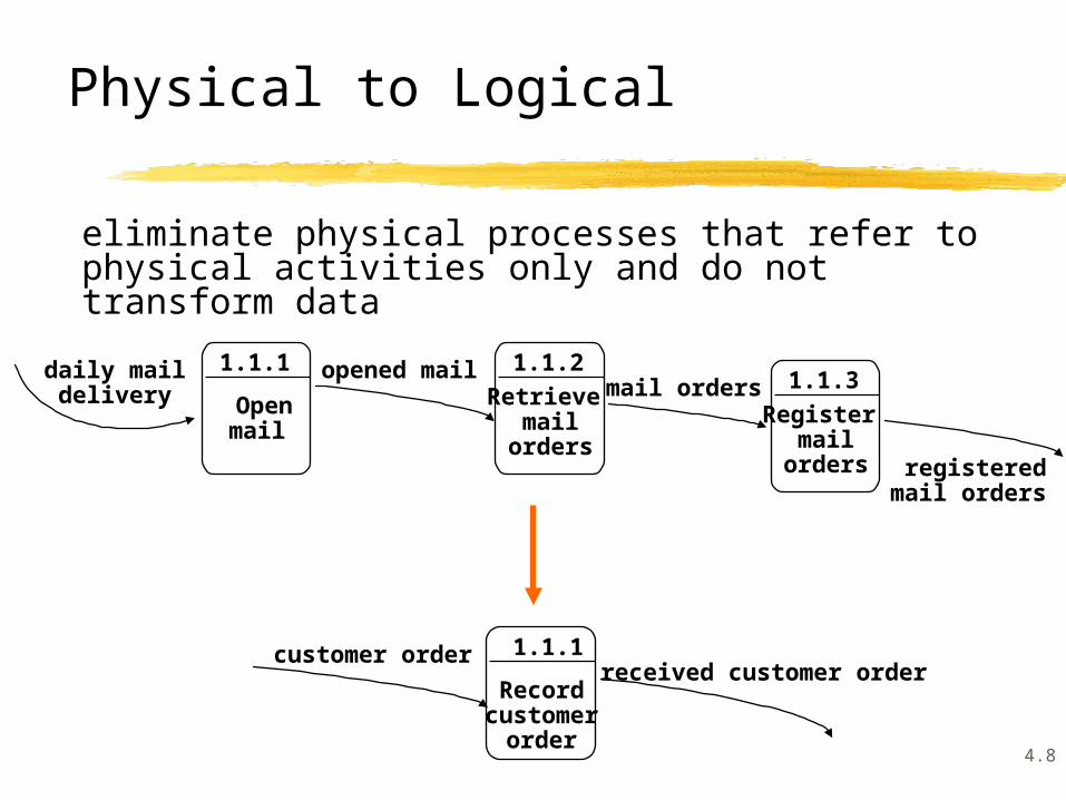
Physical to Logical DFDs

4.7
2.1
Billchecksform
2.1
Validatesalesorder
AZ104 formchecked AZ104 form
sales order
valid sales order
Master File
Sales orders
Physical to Logical DFDs
4.8
eliminate physical processes that refer to physical activities only and do not transform data
Record customer
order
1.1.1
Openmail
1.1.1
Retrieve mail
orders
1.1.2daily maildelivery
Register mail
orders
1.1.3opened mailmail orders
registeredmail orders
customer orderreceived customer order
Physical to Logical

4.9
Physical to Logical
remove any data stores that are implementation dependent
Transaction file
Master file
Employeesemployee details
Validatetrans-actions
1.1.1
Updatemaster
file
1.1.2
Validateemployee
details
1.1.1
transactions
4.10
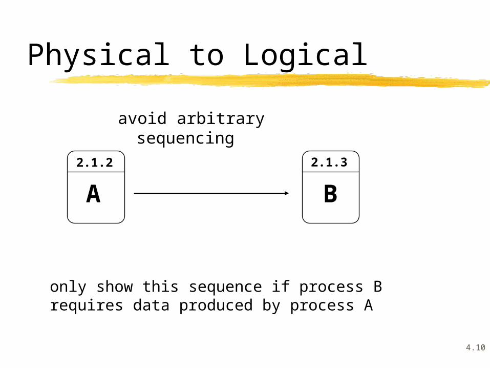
Physical to Logical
avoid arbitrary sequencing
2.1.32.1.2
A
only show this sequence if process B requires data produced by process A
B

4.11
Physical to Logical
consider the implications for processing cycles of
showing data stores
Sales orders
Validatesalesorder
1.1.1
Producecustomerinvoice
1.1.2
1.1.1
sales order
1.1.2
customer invoice
Validatesalesorder
Producecustomerinvoice
sales order customer invoice
OR
valid sales order

4.12
Example Physical DFD and Logical DFD
AZ4-order form
processedorders
Ordersclerk
2..1.1
Sort intoorder
number
2..1.2 2.1.3Sorted orders file
reject
checkedorder forms
Run the orders
program
Checksales
orders
2..1.1
Checkstock
available
2..1.2Complete
salesorders
2..1.3
reject
sales orders valid salesorders
filled sales orders
Stock file
Products
accepted sales orders
an example physical DFD for part of an order processing system
a logical DFD derived from the physical DFD above

4.13
Logical and Physical DFDs
Physical DFDs Logical DFDs
View How processing is What the system does implemented
Processes Actual sequence Essential sequence
Naming Forms, locations, Underlying data and people/roles activities
Data flows Excess/duplicated data Only essential inputs for implementation and outputs of the
needs processes

4.14
Building a Set of Data Flow Diagrams
originally there were four different types of DFDs used in a four stage modelling process:
current physical modelbuild a set of physical DFDs representing the current system
current logical modelderive a logical equivalent
new logical model incorporate new system requirements identified new physical model
add physical implementation details to reflect the selected implementation option

4.15
Building a Set of Data Flow Diagrams
disadvantages of the four stage modelling approach:
unnecessary emphasis on detailed modelling of existing system inhibits creative problem solving and redesign
preferred approach:
create a set of physical DFDs for the current system which are detailed enough to understand and grasp any problems
focus on the essential model of the system, i.e. the new logical model which identifies what the new system must do
4.16
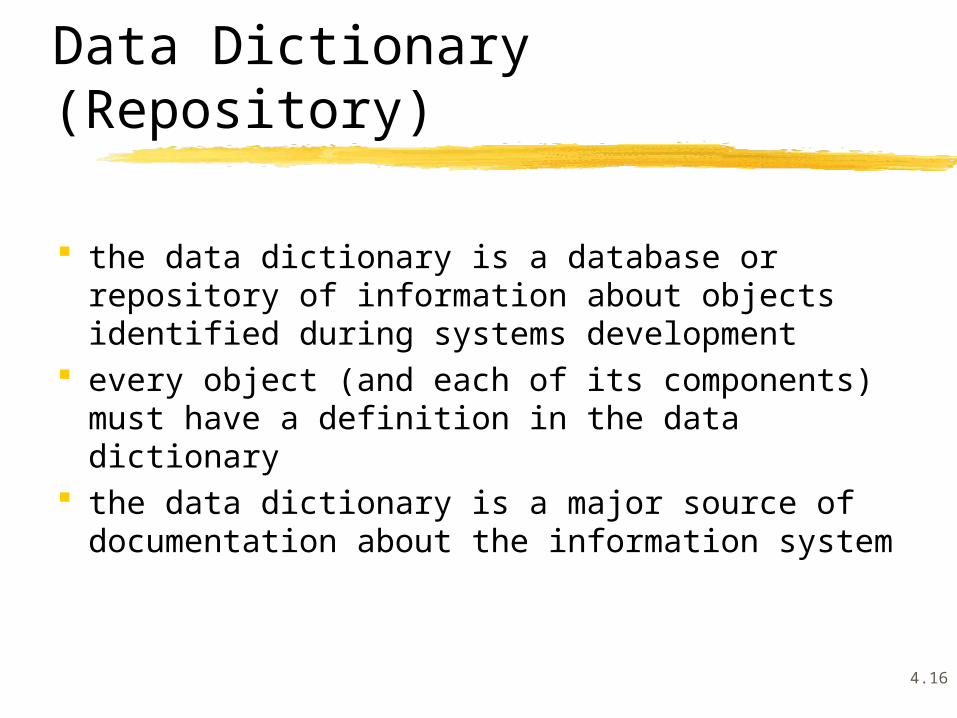
the data dictionary is a database or repository of information about objects identified during systems development
every object (and each of its components) must have a definition in the data dictionary
the data dictionary is a major source of documentation about the information system
Data Dictionary (Repository)

4.17
Data Dictionary Entries for Components of DFDs
the data dictionary must contain precise definitions of all components of all data flow diagrams: to fully explain the meaning of the DFDs to describe the contents of all data flows and
data stores to describe the processing that occurs in
primitive processes to ensure that names and meanings of
components are used consistently (a common vocabulary)

4.18
Data Dictionary Entries
a data dictionary entry must be included for each data flow data store higher level process primitive process external agent (source/sink)

4.19
each data flow consists of a series of data elements a data element is a unit of data that
cannot be further broken down into meaningful units of data
each data element should also have an entry in the data dictionary
data flows and data stores are made up of data elements
Data elements

4.20
Data Elements
a data dictionary entry for a data element should include any aliases (alternative names), a brief description of its meaning, the kinds of values it can take, and the range of values it can have (if appropriate)
E.g. Data element: product codeAlias: product numberDescription: identifies a product held in the warehouseValues: must be a positive integerRange: between 1000 and 5000

4.21
Data Flows
a data dictionary entry for a data flow describes the sequence of data elements and data structures in the data flow using the following connectors: = is equivalent to + and [ ] select one of { } iterations of ( ) optional * comments

4.22
Example Data Flow Entry
sales order = sales order no. +sales order date +customer number+[account customer
cash customer] +customer name +customer address+(customer telephone no) +{item no + item desc + item price +item qty} +sales order total amount

4.23
Data Stores
a data store is made up of data flows and data elements
where a data store consists of a collection of data flows it is described as repetitions of that data flow
e.g. Data Store: {customer invoice} data stores may also be described by listing their
data elements e.g customer deposit = account no +
deposit date +deposit amount +account balance

4.24
Describing Processes
each process in higher level DFDs is defined by the DFD that decomposes the process at the next level down: these are parent processes
each such process should have a data dictionary entry which includes a brief description of the overall nature and purpose of the process

4.25
Describing Processes
example data dictionary entry for a process
Treat patients: Patient consultations are carried out to determine the causes of patients’ illnesses/ medical problems. Further treatment/ follow up is recommended if appropriate. Details of consultations are recorded.
specific process description (minispecs)

4.26
Describing External Agents
each external agent (source or sink) should have a data dictionary entry which describes its relationship with the system
e.g.Referring Doctors:
These are doctors who refer their patients to a specialist medical practitioner for treatment. They are usually general practitioners.

4.27
Building and Maintaining the Data Dictionary
determine standard formats and information content for all types of data dictionary entries
have a standard means of organising and storing the entries in the data dictionary
ensure that all components of the DFDs have entries in the data dictionary and that they are kept up-to-date
cross-referencing of entries in the data dictionary can help to check the completeness and consistency of the DFDs and other types of models
4.28
Detailed Process Definitions
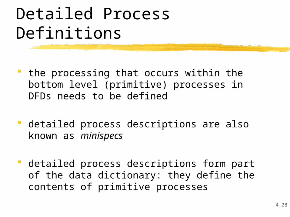
the processing that occurs within the bottom level (primitive) processes in DFDs needs to be defined
detailed process descriptions are also known as minispecs
detailed process descriptions form part of the data dictionary: they define the contents of primitive processes
4.29
Detailed Process Definitions
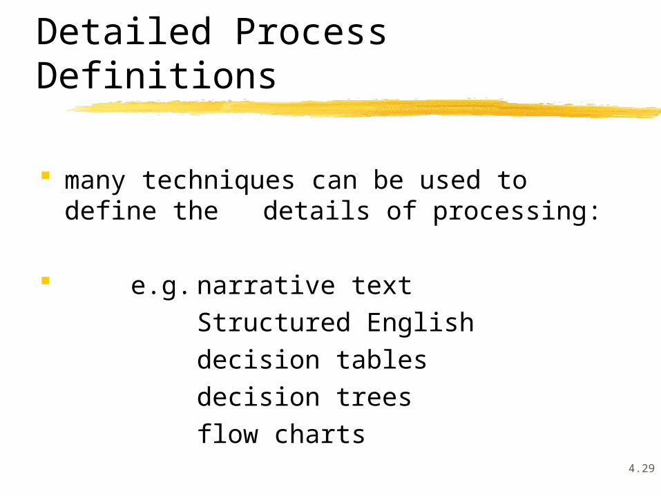
many techniques can be used to define the details of processing:
e.g. narrative textStructured Englishdecision tablesdecision treesflow charts
4.30
Detailed Process Definitions
detailed process descriptions should:
express what the process does (i.e. policy), not how the process is carried out (i.e. procedure)
be in a form that can be easily understood and verified by both users and systems analysts
be in a form that can be easily communicated to all potential stakeholders:
e.g. end-users, systems analysts, managers, system designers, project leaders, programmers
4.31
Structured English
Structured English is a modified form of English with some major restrictions on vocabulary and structure:
only action (imperative) verbs such as get, put, add, calculate, find, delete are used
only nouns/noun phrases which refer to components of the DFDs should be used, i.e. data flows, data stores, data elements
4.32
Structured English
sentences consist of action verbs and DFD components
sentences are combined to form process descriptions using the control structures of sequence, condition, and repetition
4.33
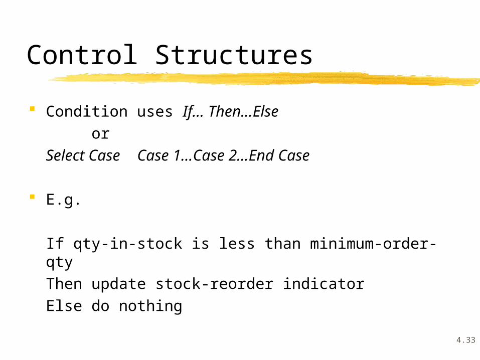
Control Structures
Condition uses If... Then...Else or
Select Case Case 1...Case 2...End Case
E.g.
If qty-in-stock is less than minimum-order-qtyThen update stock-reorder indicatorElse do nothing

4.34
Control Structures e.g.Select Case
CASE 1 qty-in-stock is less than minimum-order-qty
Do update stock-reorder indicatorCASE 2 qty-in-stock is equal to minimum-order-qty
Do nothingCASE 3 qty-in-stock is greater than minimum-order-qty
Do nothingEnd Case

4.35
Sequence is represented with one sentence following another in sequence:
Add student to class listDecrease available-placesCalculate class-fee
Control Structures

4.36
Repetition uses Do-Until or Do-While loops:
DoAccept customer-account-detailsCalculate daily-interest = daily balance *
daily interest rateAdd daily-interest to monthly-interest-due
Untilno more customer-accounts
Control Structures

4.37
Example Structured English
Accept sales-orderFind customer-detailsIf customer-details not found
Then reject sales-orderElse
Create sales-order-headerDo while more sales-order-items
find item-detailscalculate sales-order-item price = item price *order-qty
EnddoAuthorise sales-order
Endif

4.38
Guidelines for Structured English
use indentation to indicate control structures and their scope: assists readability and understanding
avoid more than three levels of nesting: complicated logic can be represented using other techniques
Stuctured English descriptions should illustrate the logic of the processing, not the implementation of the processing

4.39
Decision Tables
decision tables are useful for describing processes where several different conditions apply and the particular actions that are taken are determined by combinations of the values of the conditions
decision tables are useful where the process logic is complex
decision tables show all the possible choices and the conditions they depend on in a tabular form

4.40
Decision Tables
decision tables have three stubs (four quadrants):
conditions rules
actions
outcomesfor each setof conditionvalues
combinations of condition values

4.41
Example Decision Table
avg account bal > $1,000
overdraft amount < $50,000previous paid-out loan
approve
conditional approval
reject
Y Y Y Y N N N N
Y Y N N Y Y N N
Y N Y N Y N Y N
X X
X
X
X
X X X

4.42
wholesalecustomer
retailcustomer
local item
local item
imported item
imported itemDetermine Customer Discount
15%
10%
12%
7%
decision trees are an alternative graphical representation of a decision situation as a connected series of nodes and branches
Decision Trees

4.43
Selecting Techniques for Process Descriptions
Structured English is useful where a process has a sequence of activities and there is no more than three levels of nesting of decisions
decision trees and decision tables are useful where a process involves a decision based on combinations of values of several conditions
4.44
Selecting Techniques for Process Descriptions
decision trees visually distinguish the decision conditions and their values from the actions: they show the paths that decisions can follow but soon become cluttered if each condition has several possible values
decision tables are able to show decisions involving many conditions each with many possible values

4.45
Overview of Process Modelling
several techniques are available for representing the processing within systems
the aim of process modelling in systems analysis is to define the processing that occurs within a system

4.46
models representing:
an overview of the system processing the structure of the system processing the flow of data into and out of the
processes the detailed logic of the processes
can be constructed
Process Modelling Techniques
4.47
References
HOFFER, J.A., GEORGE, J.F. and VALACICH (2005) Modern Systems Analysis and Design, (4th edition), Pearson Education Inc., Upper Saddle River, New Jersey, USA. Chapters 7, 8
WHITTEN, J.L., BENTLEY, L.D. and DITTMAN, K.C. (2001) 5th ed., Systems Analysis and Design Methods, Irwin/McGraw-HilI, New York, NY. Chapter 8