Embed Size (px)
Citation preview

40/10 VF
www.fermator.com
NEW INSTALLATION
RESIDENTIALLIFTS
Automatic horizontal sliding car door
ENGPRINTABLE VERSION: 04-12-2015DOC-FECMCBP4VC00EN

www.fermator.com 240/10 VF
Door configuration
STANDARDS
Opening EN 81-1/2Safety rules
EN 81-21Existing buildings
EN 81-41Impaired mobility
EN 81-71Vandal resistance lifts EN 81-72
Firefighters liftsEN 81-1/2
Safety rulesCat. I Cat. IIC2 - C4 - C6 - C8T1 - T2 - T3 - T4
PANELS
Opening
Steel panels Glass panels
Metal sheet (1)
Double skin Vision Gridded
vision
Wien type
visionBevel big
visionFlush big
vision Full glassFull glass
built in moorings
Full glass concealed
trimsAluminium
glass
WC2 - C4 - C6 - C8
T1 - T2 - T3 - T4
1 Solid execution option.
PROTECTION
Opening
IP21Protection against a solid foreign body of 12,5 mm or more in
diameter and protected against vertically falling
drops of water.
IPX3Protected against
sprays of water up to 60 degrees from the vertical.
IP54Protection against dust and protected against water
splashed from all directions.
IP65Sealed against dust and protected against jets of water from all directions.
EExExplosion proof, Group II (surface industries) and Category 2 (explosive
atmosphere between 10 and 1.000 hrs/yr).
Magnetic contact Mechanical contactC2 - C4 - C6 - C8T1 - T2 - T3 - T4
APPLICATION RANGE
Opening Clear opening - PL (mm) Clear height - HL (mm)
C2 600 - 1.400
2.000 - 2.300
C4 600 - 2.400 C6 1.200 - 3.000C8 1.400 - 3.000T1 600 - 1.000T2 600 - 1.200
T3 - T4 600 - 1.400
LIFT APPLICATION Door cycles per year: Up to 800.000.Traffic peak of the door: Up to 240 cycles per hour.
Traffic lift speed: Up to 2,5 m/s.
Available1. Ask the commercial department.Not available.1Some option combinations may not be possible.
SILLS
Type of sill Aluminium Reinforced aluminium Steel Steel concealed Massive
Profile detail -
Availability Heated sill option (1)
Dust holes Sill support
1 Not available for C2.

www.fermator.com3 40/10 VF
Door configuration
SAFETY DEVICES
Opening Photocell Photoelectric barrier Safety edge Emergency power supplyStatic Dynamic VF4+ VF5 VF6
C2 - C4 - C6 - C8T1 - T2 - T3 - T4
PANEL REGULATION SUPPORT AND PANEL GUIDE
Type of panel regulation support Plus
Type of panel guide Plus
CAMS
Compatibility Semiautomatic hinged landing door: Aluminium - Glass, Global, Fermator, B+
Type of cam Frontal retractable Lateral retractable Inverted retractable Flexible fixed Fixed
Cam detail
90 903030
90 60
14082
±0
400
560
210
HL + 285
HL
AFO: HL + 220
HL + 500
MO
TOR
H
Case 40/10 landing doorCoupling Symmetrical clutch Pre-opening symmetrical clutch
Unlocking zone +111 / -290 +261 / -290Toe guard type Big 2 section 3 section
H* 750 812(495)
798(405)
Thickness 1,5 1,5 1,5Range All 650 - 1.200 650 - 1.200
*Contracted toe guard dimension between brackets.T2 opening shown.
If not otherwise indicated all dimensions in mm.
COMPATIBILITY
Available1. Ask the commercial department.Not available.1Some option combinations may not be possible.

www.fermator.com 440/10 VF
DRIVEType Asynchronous three-phase motor.
Efficiency 60%.Consumptions Standby 4 W / Average per cycle 50 W.Transmission Gearless. PL 600 - 3.000 mm. HTD belt.
T2 operator
Technical features
ELECTRONIC MODULEType VF4+, VF5 and VF6.
Adjustable parameters via PC / Console.Working signals available From 12 V to 230 V AC/DC or with BUS CAN (Only for VF6).
Opening speed Up to 1 m/s. Manually adjustable and auto-adjustable directly with the panel weight.Closing speed Up to 0,6 m/s. Manually adjustable and auto-adjustable directly with the panel weight.
Re-opening Integrated with auto-adjustable cycles.
GENERAL FEATURESNoise level < 53 dB.Total weight Reference: T2 PL 800 mm HL 2.000 mm, with sheet metal panels - 71 kg.
Maximum moving mass 250 kg.Locking device Car door lock.
INSTALLATIONPre-adjusted and tested to simplify the installation.

www.fermator.com5 40/10 VF
195
≥ 30
160
=O
=
225
225
==
560
54
30
5475
100
120 120
100 50 150
245
495
305
H
54
265
390
117 54
30
20
≥ 30
100
N
N
+0 -50
4850
5050
50
2PL + 50
PL
HL
+ 11
0
HL
+ 50
0
PL/2 + 20
2PL + 40
PL/2PL/2
PL/4 PL/4
PL
HL
+ 23
5
HL
+ 23
5
HL
PL ≥ 1.100
CARFLOOR
H
Con
cent
ricØ
48
Ecce
ntric
Ø 4
8
Technical drawing 2 panel centre parting door
MECHANICALDETAILS
FIXING BRACKETRANGE
SILLDETAIL
thicknessPL ≤ 700 = 3
PL ≥ 750 = 2,5
54 mm sill
N Recomended vertical fixing point for brackets.- If not otherwise indicated all dimensions in mm.
Notes:
PL 600 650 700 750 800 850 900 1.000 1.100 1.200 1.300 1.400O 1.200 1.250 1.400 1.450 1.500 1.550 1.600 1.700 1.800 2.200 2.300 2.400

www.fermator.com 640/10 VF
N
N
120 120 6090
30
9075
100
125
15050 50 100100245
==
5
30
B= =
= =
125
265
390
305
90
405 405
81,5
54
20
≥ 30
4850
5050
50 195
≥ 30
+0 -50
PL
PL/4 + 20
1,5PL + 40
PL/2 PL/2
PL/4PL/4
PL1,5PL + 50
HL
+ 11
0
HL
HL
+ 50
0H
L +
235
HL
+ 23
5
PL 1.100 - 1.150
H
CARFLOOR
Con
cent
ricØ
48
Ecce
ntric
Ø 4
8
Technical drawing 4 panel centre parting door
MECHANICALDETAILS
FIXING BRACKETRANGE
SILLDETAIL
90 mm sill Single coupling system (PL 600 - 1.150)
thickness3
N Recomended vertical fixing point for brackets.B For PL ≤ 900 = 100. For PL ≥ 950 = 160.- If not otherwise indicated all dimensions in mm.
Notes:

www.fermator.com7 40/10 VF
N
N
≥ 30
230 D245D
==
120 120 6090
90
30
7510
0 305
90
405 405
265
390
4850
5050
50
160= == =
D D160
5
30
81,5
54
20
≥ 30
100 10050
195
+0 -50
PL/2
PL/4 PL/4
PL/2
PL
PL1,5PL + 50
PL/4 + 20
1,5PL + 40
HL
+ 11
0
HL
HL
+ 50
0H
L +
235
HL
+ 23
5
H
CARFLOOR
Con
cent
ricØ
48
Ecce
ntric
Ø 4
8
FIXING BRACKETRANGE
thickness3
Technical drawing 4 panel centre parting door
MECHANICALDETAILS
SILLDETAIL
90 mm sillDouble coupling system (PL 1.200 - 2.400)
N Recomended vertical fixing point for brackets.- If not otherwise indicated all dimensions in mm.
Notes:
PL 1.200 1.300 1.400 1.500 1.600 1.700 1.800 1.900 2.000 2.100 2.200 2.300 2.400D 88 88 125 125 125 175 175 225 225 277 277 325 325

www.fermator.com 840/10 VF
N
N
120 120 6090
30
7075
100
125
150245
==
5
B= =
= =
125
265
390
50
50
5050
48
305
70
305 305
91,5
30
54
20
≥ 30
10050
100
195
≥ 30
+0 -50
PL/4 + 20
1,5PL + 40
PL
PL/2
PL/4
PL/2
PL1,5PL + 50
HL
+ 11
0
HL
HL
+ 50
0
HL
+ 23
5
PL/4
HL+
235
PL 1.100 - 1.150
H
CARFLOOR
Con
cent
ricØ
48
Ecce
ntric
Ø 4
8
Technical drawing 4 panel centre parting door
MECHANICALDETAILS
FIXING BRACKETRANGE
SILLDETAIL
thickness3
70 mm sillSingle coupling system (PL 600 - 1.150)
N Recomended vertical fixing point for brackets.B For PL ≤ 750 = 100. For PL ≥ 800 = 160.- If not otherwise indicated all dimensions in mm.
Notes:

www.fermator.com9 40/10 VF
N
N
230 D245D
=
100 100
=
120 120 60
30
9070
7510
0 305
70
305 305
265
390
50
5050
5048
160= == =
D D160
5
91,5
30
20
54
≥ 30
195
≥ 30
+0 -50
PL/2
PL/4 PL/4
PL/2
1,5PL + 40
PL
PL1,5PL + 50
PL/4 + 20
HL
+ 11
0
HL
HL
+ 50
0
HL
+ 23
5
HL+
235
H
CARFLOOR
Con
cent
ricØ
48
Ecce
ntric
Ø 4
8
N Recomended vertical fixing point for brackets.- If not otherwise indicated all dimensions in mm.
Notes:
FIXING BRACKETRANGE
Technical drawing 4 panel centre parting door
MECHANICALDETAILS
SILLDETAIL
70 mm sill Double coupling system (PL 1.200 - 2.400)
thickness3
PL 1.200 1.300 1.400 1.500 1.600 1.700 1.800 1.900 2.000 2.100 2.200 2.300 2.400D 88 88 125 125 125 175 175 225 225 277 277 325 325

www.fermator.com 1040/10 VF
N
N
120 120
6090
30
8075
100
125
150245
==
5
30
B= =
= =
125
390 26
5
5050
50
5048
30
10
5
305 50
905
91,5
54
20
≥ 30
100
50
100
195
≥ 30
+0 -50
PL
PL/4 + 20
1,5PL + 40
PL/2
PL/4 PL/4
PL/2
PL1,5PL + 50
HL
+ 11
0
HL
HL
+ 50
0
HL
+ 23
5
HL
+ 23
5
H
CARFLOOR
Con
cent
ricØ
48
Ecce
ntric
Ø 4
8
Technical drawing 4 panel centre parting door
FIXING BRACKETRANGE
MECHANICALDETAILS
SILLDETAIL
thickness3
80 mm sill
N Recomended vertical fixing point for brackets.B For PL ≤900 = 100. For PL ≥ 950 = 160.- If not otherwise indicated all dimensions in mm.
Notes:

www.fermator.com11 40/10 VF
N
N
295
420
4850
5050
50
160= =
C
= =
D D160
30
5
230 D245
==
225 22550
30
135
7510
0
120 120
6013
5
305
405 405
40
5135
20
195
≥ 30
+0 -50
250
≥ 30
+0 -175
≥ 30
PL
1,35PL + 40
PL/6 + 20
PL/2
PL/4 PL/4
PL/8PL/8
PL/2
PL
HL
+ 11
0
HL
+ 23
5H
L
HL
+ 53
0
HL
+ 23
5
HL
+ 23
5
H
Con
cent
ricØ
48
Ecce
ntric
Ø 4
8
CARFLOOR
Technical drawing 6 panel centre parting door
FIXING BRACKETRANGE
MECHANICALDETAILS
SILLDETAIL
thickness3
135 mm sill
N Recomended vertical fixing point for brackets.- If not otherwise indicated all dimensions in mm.
Notes:
PL 1.200 1.300 1.400 1.500 1.600 1.700 1.800 1.900 2.000 2.100 2.200 2.300 2.400 2.500 2.600 2.700 2.800 2.900 3.000C 1.650 1.800 1.950 2.050 2.200 2.350 2.450 2.600 2.750 2.850 3.000 3.150 3.250 3.400 3.550 3.650 3.800 3.950 4.050

www.fermator.com 1240/10 VF
N
N
20
195
≥ 30
250
≥ 30
+0 -50
+0 -175
16090 90160 ===
420
30
48
295
230
90
275
90 ==
6018
0 30
180
7510
0
120 120
305
405 405
40 405
5
5
5050
50 50
195 1955050
HL
+ 23
5
HL
+ 23
5
PL1,25PL+ 50
PL/2 PL/2PL/4PL/4
PL/8 PL/8
PL/8 + 20 1,25PL + 40
PL
HL
+ 11
0
HL
HL
+ 53
0
HL
+ 23
5
Con
cent
ricØ
48
Ecce
ntric
Ø 4
8
CARFLOOR
H
SILLDETAIL
FIXING BRACKETRANGE
MECHANICALDETAILS
N Recomended vertical fixing point for brackets.- If not otherwise indicated all dimensions in mm.
Notes:
Technical drawing 8 panel centre parting door
180 mm sill
thickness3

www.fermator.com13 40/10 VF
54 mm sill
N
N
4850
5050 50
160
85
25
230
85
25
27575
50
5
30
265
390
120
15
120
305
49
54
5
117
6054 30
5475
100
20
54
≥ 30
195
≥ 30
+0 -50
20
150
PL
2PL + 50
PL + 20
2PL + 40
PL + 200
PL
PL
HL
+ 11
0
HL
+ 50
0
HL
+ 2
35
HL
HL
+ 23
5
PL
H
CARFLOOR
Con
cent
ricØ
48
Ecce
ntric
Ø 4
8
SILLDETAIL
MECHANICALDETAILS
FIXING BRACKETRANGE
Technical drawing 1 panel side opening door
N Recomended vertical fixing point for brackets.- If not otherwise indicated all dimensions in mm.
Notes:
thickness2,5

www.fermator.com 1440/10 VF
N
N
195
≥ 30
16025
90
265
390
4850
5050
50
5
30
230
90
25
200
245 15
120 120
81,5
6090
30
9075
100 30
5
90
405 405
20
54
≥ 30
100 50
+0 -50
20
PL
1,5PL + 50
HL
+ 50
0
HL
+ 23
5
1,5PL + 40
HL
+ 11
0
PL/2 + 20
PL + 200
PL
(PL-175)/2 (PL-175)/2
PL
HL
HL
+ 23
5
PL
Con
cent
ricØ
48
Ecce
ntric
Ø 4
8
CARFLOOR
H
Technical drawing 2 panel side opening door
SILLDETAIL
FIXING BRACKETRANGE
MECHANICALDETAILS
thicknessPL ≤ 700 = 3 PL ≥ 750 = 2,5
90 mm sill
N Recomended vertical fixing point for brackets.- If not otherwise indicated all dimensions in mm.
Notes:

www.fermator.com15 40/10 VF
MECHANICALDETAILS
Technical drawing 2 panel side opening door
N
N
160
25
90
5
30
265
390
4850
5050
50
230
90
25
200100 50
245 15
6090
30
7075
100
120 120
305
305 30
570
91,5
54
20
≥ 30
195
≥ 30
20
+0 -50
PL1,5PL + 50
PL/2 + 20
1,5PL + 40
PL + 200
PL
(PL-175) / 2(PL-175) / 2
PL
HL
+ 11
0
HL
+ 50
0
HL
+ 23
5
HL
HL
+ 23
5
PL
CARFLOOR
H
Con
cent
ricØ
48
Ecce
ntric
Ø 4
8
SILLDETAIL
FIXING BRACKETRANGE
thicknessPL ≤ 1.050 = 3
PL ≥ 1.100 = 2,5
70 mm sill
N Recomended vertical fixing point for brackets.- If not otherwise indicated all dimensions in mm.
Notes:

www.fermator.com 1640/10 VF
Technical drawing 3 panel side opening door
N
N
16025
90
5050
4850
50
C
295
420
5
30
230
85
25
275
232,55038,5
15
6013
5
30
135
7510
0
120 120
305
405 40
1355
405
36,5
54
20
≥ 30
195
≥ 30
+0 -50
20
PL
PL/3 + 20
1,35PL + 40
PL + 200
PL / 2 (PL / 2) -210
PL
PL
HL
+ 11
0
HL
HL
+ 53
0
HL
+ 23
5
PL 1.400
HL
+ 23
5
PL
H
CARFLOOR
Con
cent
ricØ
48
Ecce
ntric
Ø 4
8
SILLDETAIL
FIXING BRACKETRANGE
MECHANICALDETAILS
thicknessPL ≤ 1.050 = 3PL ≥ 1.100 = 2,5
135 mm sill
N Recomended vertical fixing point for brackets.- If not otherwise indicated all dimensions in mm.
Notes:
PL 600 650 700 750 800 850 900 1.000 1.100 1.200 1.300 1.400C 895 945 995 1.045 1.120 1.195 1.245 1.395 1.545 1.695 1.795 1.945
www.fermator.com17 40/10 VF
N
N
B70
C
295
420
4850
5050
50
5
30
230
80
275
35
100 50
200 50(1)
6018
0
30
180
7510
0
120 120
405 40
55
1805
40 40
305
15
54
20
≥ 30
195
≥ 30
+0 -50
20
PL 75 (PL > 900 = 25)
PL/4 + 201,25PL + 40
PL
(PL-175) / 2 (PL-175) / 2
75 (PL > 900 = 25)
PL
HL
+ 11
0
HL
HL
+ 53
0
HL
+ 23
5
PL 1.400 HL
+ 23
5
PL
CARFLOOR
H
Con
cent
ricØ
48
Ecce
ntric
Ø 4
8
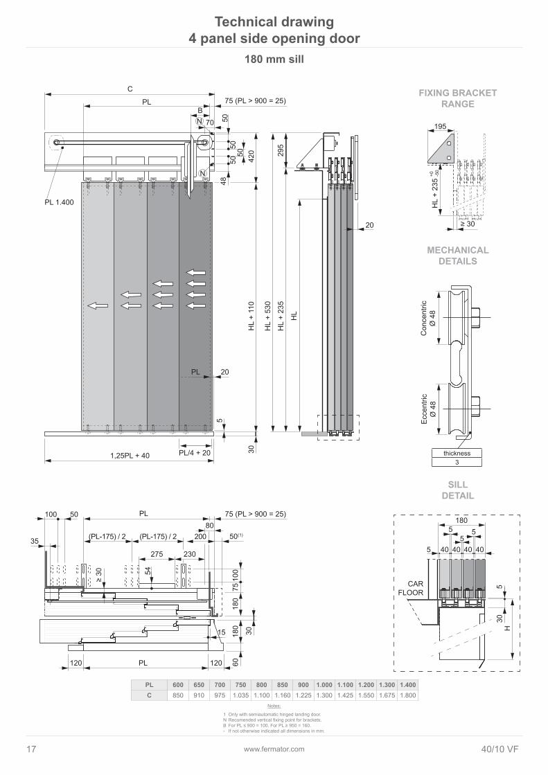
Technical drawing 4 panel side opening door
SILLDETAIL
FIXING BRACKETRANGE
MECHANICALDETAILS
thickness3
180 mm sill
1 Only with semiautomatic hinged landing door.N Recomended vertical fixing point for brackets.B For PL ≤ 900 = 100. For PL ≥ 950 = 160.- If not otherwise indicated all dimensions in mm.
Notes:
PL 600 650 700 750 800 850 900 1.000 1.100 1.200 1.300 1.400C 850 910 975 1.035 1.100 1.160 1.225 1.300 1.425 1.550 1.675 1.800

www.fermator.com 1840/10 VF
N
N
B70
C1
295
5
30
230
85
275
35
6018
0
30
140
7510
0
120 120
305 305
5140
530 30
42050
5050
5048
36,5
15
54
20
≥ 30
200
100 50
195
≥ 30
+0 -50
20
305
PL 75 (PL > 900 = 25)
PL/4 + 201,25PL + 40
PL 75 (PL > 900 = 25)
PL
HL
+ 11
0
HL
HL
+ 53
0
HL
+ 23
5
PL 1.400
(PL-175) / 2 (PL-175) / 2
HL
+ 23
5
PL
CARFLOOR
H
Con
cent
ricØ
48
Ecce
ntric
Ø 4
8
FIXING BRACKETRANGE
thickness3
Technical drawing 4 panel side opening door
SILLDETAIL
MECHANICALDETAILS
140 mm sill
1 For semiautomatic hinged landing door C = C - 50.N Recomended vertical fixing point for brackets.B For PL ≤ 900 = 100. For PL ≥ 950 = 160.- If not otherwise indicated all dimensions in mm.
Notes:
PL 600 650 700 750 800 850 900 1.000 1.100 1.200 1.300 1.400C 850 910 975 1.035 1.100 1.160 1.225 1.300 1.425 1.550 1.675 1.800

www.fermator.com19 40/10 VF

Fermator reserves the right to make changes to the specification of the products within this catalogue without prior notice.
General: [email protected]: [email protected] • Brazil: [email protected] • Italy: [email protected] • France: [email protected], [email protected]
China: [email protected] • India: [email protected] • Poland: [email protected] • Germany: [email protected]
Sales contacts


![HAAS VF-3YT 40 00288 · 2019. 10. 14. · Revised: 30-DEC-11 HAAS VF-3YT 40 00288.pdf Page 3 of 13 Notes All dimensions are MM [IN] FOUNDATION INTERFACE 5VP-HAAS-00288 This workholding](https://img.dokumen.tips/doc/110x75/613b5333f8f21c0c8268efb4/haas-vf-3yt-40-00288-2019-10-14-revised-30-dec-11-haas-vf-3yt-40-00288pdf.jpg)