Embed Size (px)
Citation preview
J&M Manufacturing Co, Inc284 Railroad Street - P.O. Box 547 | Fort Recovery, OH 45846 | Ph: (419) 375-2376 | Fax: (419) 375-2708
www.jm-inc.com
Rev.
8.1
8.20
20
4 W h e e l S t e e rH E A D E R T R A N S P O R T
MODEL
Operator’s Manual


3
Table Of Contents
4 . . . . . . . . . . . . . . . . . . . . . . . . . . . . . . . . . . . . . . . . . . . . . . . . . . . . . . . . . . . . . . . . . . . . . . . . . . . . . . . . . . . .To the Dealer 5 . . . . . . . . . . . . . . . . . . . . . . . . . . . . . . . . . . . . . . . . . . . . . . . . . . . . . . . . . . . . . . . . . . . . . . . . . . . . .General Information 6 . . . . . . . . . . . . . . . . . . . . . . . . . . . . . . . . . . . . . . . . . . . . . . . . . . . . . . . . . . . . . . . . . . . . . . . . . . . . . . . . . . . . .Safety Rules 7 . . . . . . . . . . . . . . . . . . . . . . . . . . . . . . . . . . . . . . . . . . . . . . . . . . . . . . . . . . . . . . . . . . . . . . . . . . . . . . . . . . . Specifications8 . . . . . . . . . . . . . . . . . . . . . . . . . . . . . . . . . . . . . . . . . . . . . . . . . . . . . . . . . . . . . . . . . . . . . . . . . . . . . . . . . . . . . . . . . . Decals9 . . . . . . . . . . . . . . . . . . . . . . . . . . . . . . . . . . . . . . . . . . . . . . . . . . . . . . . . . . . . . . . . . . . . . . . Bolt Torque Specifications10 . . . . . . . . . . . . . . . . . . . . . . . . . . . . . . . . . . . . . . . . . . . . . . . . . . . . . . . . . . . . . . . . . . . . . . . Operations/Maintenance12 . . . . . . . . . . . . . . . . . . . . . . . . . . . . . . . . . . . . . . . . . . . . . . . . . . . . . . . . . . . . . . . . . Hub and Bearing Maintenance13 . . . . . . . . . . . . . . . . . . . . . . . . . . . . . . . . . . . . . . . . . . . . . . . . . . . . . . . . . . . . . . . . . . . . . . . . . . . . .Set-Up Instructions24 . . . . . . . . . . . . . . . . . . . . . . . . . . . . . . . . . . . . . . . . . . . . . . . . . . . . . . . . . . . . . . . . . . . . . . . . . . . . . . . . . . . . . . . . . . Axles25 . . . . . . . . . . . . . . . . . . . . . . . . . . . . . . . . . . . . . . . . . . . . . . . . . . . . . . . . . . . . . . . . . . . . . . . . .7k Idler Hub and Wheel26 . . . . . . . . . . . . . . . . . . . . . . . . . . . . . . . . . . . . . . . . . . . . . . . . . . . . . . . . . . . . . . . . . . . . . . . . . . . . . Brakes for 7k Axles26 . . . . . . . . . . . . . . . . . . . . . . . . . . . . . . . . . . . . . . . . . . . . . . . . . . . . . . . . . . . . . . . . . . . . . . . . . . . . . . Lifting Arms Ends27 . . . . . . . . . . . . . . . . . . . . . . . . . . . . . . . . . . . . . . . . . . . . . . . . . . . . . . . . . . . . . . . . . . . . . . . . . . . . Lifting Arms Middle28 . . . . . . . . . . . . . . . . . . . . . . . . . . . . . . . . . . . . . . . . . . . . . . . . . . . . . . . . . . . . Header Mount and Tie Down Straps32 . . . . . . . . . . . . . . . . . . . . . . . . . . . . . . . . . . . . . . . . . . . . . . . . . . . . . . . . . . . . . . . . . . . . . . . . . . . . . . Lights and Wiring32 . . . . . . . . . . . . . . . . . . . . . . . . . . . . . . . . . . . . . . . . . . . . . . . . . . . . . . . . . . . . . . . . . . . . . . . . . . . . . . . Spare Tire Mount

4
TO THE DEALER
Read manual instructions and safety rules. Make sure all items on the Dealer’s Pre-Delivery and Delivery Check Lists are completed before releasing equipment to the owner.The dealer must complete the Warranty Registration found on the Dealer Portal website located at dealer.jm-inc.com and return it to J&M Mfg. Co., Inc. at the address indicated on the form. Warranty claims will be denied if the Warranty Registration has not been submitted.
EXPRESS WARRANTY:
J&M Mfg. Co. Inc. warrants against defects in construction or materials for a period of ONE year. We reserve the right to inspect and decide whether material or construction was faulty or whether abuse or accident voids our guarantee.
Warranty service must be performed by a dealer or service center authorized by J&M Mfg. Co., Inc. to sell and/or service the type of product involved, which will use only new or remanufactured parts or components furnished by J&M Mfg. Co., Inc. Warranty service will be performed without charge to the purchaser for parts or labor based on the Warranty Labor Times schedule. Under no circumstance will allowable labor times extend beyond the maximum hours indicated in the Warranty Labor Times schedule for each warranty procedure. The purchaser will be responsible, however, for any service call and/or transportation of the product to and from the dealer or service center’s place of business, for any premium charged for overtime labor requested by the purchaser, and for any service and/or maintenance not directly related to any defect covered under the warranty. Costs associated with equipment rental, product down time, or product disposal are not warrantable and will not be accepted under any circumstance.
Each warranty term begins on the date of product delivery to the purchaser. Under no circumstance will warranty be approved unless (i) the product warranty registration card has been properly completed and submitted to the equipment manufacturer, and (ii) a warranty authorization number has been issued by the equipment manufacturer. This Warranty is effective only if the warranty registration card is returned within 30 days of purchase.
This warranty does not cover a component which fails, malfunctions or is damaged as a result of (i) improper modification or repair, (ii) accident, abuse or improper use, (iii) improper or insufficient maintenance, or (iv) normal wear or tear. This warranty does not cover products that are previously owned and extends solely to the original purchaser of the product. Should the original purchaser sell or otherwise transfer this product to a third party, this warranty does not transfer to the third party purchaser in any way. J&M Mfg. Co., Inc. makes no Warranty, express or implied, with respect to tires or other parts or accessories not manufactured by J&M Mfg. Co., Inc. Warranties for these items, if any, are provided separately by their respective manufacturers.
THIS WARRANTY IS EXPRESSLY IN LIEU OF ALL OTHER WARRANTIES OR CONDITIONS, EXPRESS, IMPLIED OR STATUTORY, INCLUDING ANY IMPLIED WARRANTY OF MERCHANTABILITY OR FITNESS FOR PARTICULAR PURPOSE.
In no event shall J&M Mfg. Co., Inc. be liable for special, direct, incidental or consequential damages of any kind. The exclusive remedy under this Warranty shall be repair or replacement of the defective component at J&M Mfg. Co., Inc’s. option. This is the entire agreement between J&M Mfg. Co., Inc. and the Owner about warranty and no J&M Mfg. Co., Inc. employee or dealer is authorized to make any additional warranty on behalf of J&M Mfg. Co., Inc.
The manufacturer reserves the right to make product design and material changes at any time without notice. They shall not incur any obligation or liability to incorporate such changes and improvements in products previously sold to any customer, nor shall they be obligated or liable for the replacement of previously sold products with products or parts incorporating such changes.
SERVICE:
The equipment you have purchased has been carefully manufactured to provide dependable and satisfactory use. Like all mechanical products, it will require cleaning and maintenance. Lubricate the unit as specified. Observe all safety information in this manual and safety signs on the equipment.
For service, your authorized J&M dealer has trained mechanics, genuine J&M service parts, and the necessary tools and equipment to handle all your needs.
Use only genuine J&M service parts. Substitute parts may void warranty and may not meet standards required for safety and satisfactory operation. Record the model number and serial number of your equipment in the spaces provided:
Model No: 4WS15/4WS17 Serial No: ________________________ Date of Purchase: ______________________
Purchased From: ________________________________________________________________________________Provide this information to your dealer to obtain correct repair parts.
To the Dealer

5
General Information
ATTENTION! BECOME ALERT! YOUR SAFETY IS INVOLVED! Safety is a primary concern in the design and manufacture of our products. Unfortunately, our efforts to provide safe equipment can be erased by an operator’s single careless act. In addition, hazard control and accident prevention are dependent upon the awareness, concern, judgment, and proper training of personnel involved in the operation, transport, maintenance and storage of equipment.
Make certain that the operator(s), prior to operating is instructed in safe and proper use and reviews and understands the manual(s) pertaining to this machine. Also make certain that the operator(s) reviews and understands the operator’s manual of the tow vehicle prior to hooking up or operating the SpeedTender.
Read this manual before you operate this machine. If you do not understand any part of this manual, or need more information, contact the manufacturer or your authorized dealer.
Safety Rules Continued on Next Page
SAFETY RULES:
TO THE OWNER:The purpose of this manual is to assist you in operating and maintaining your header transport in a safe manner. Read it carefully. It furnishes information and instructions that will help you achieve years of dependable performance and help maintain safe operating conditions. If this machine is used by an employee or is loaned or rented, make certain that the operator(s), prior to operating:1. Is instructed in safe and proper use.2. Reviews and understands the manual(s) pertaining to this machine.Throughout this manual, the term IMPORTANT is used to indicate that failure to observe can cause damage to equipment. The terms CAUTION, WARNING and DANGER are used in conjunction with the Safety-Alert Symbol, (a triangle with an exclamation mark), to indicate the degree of hazard for items of personal safety. When you see this symbol, carefully read the message that follows and be alert to thepossibility of personal injury or death.
DANGER
WARNING
CAUTION
This Safety-Alert symbol indicates a hazard and meansATTENTION! BECOME ALERT! YOUR SAFETY IS INVOLVED!
Indicates an imminently hazardous situation that, if not avoided, will result in death or serious injury.
Indicates a potentially hazardous situation that, if not avoided, could result in death or serious injury, and includes hazards that are exposed when guards are removed.
Indicates a potentially hazardous situation that, if not avoided, may result in minor or moderate injury.
Indicates that failure to observe can cause damage to equipment.
Indicates helpful information.
IMPORTANT
NOTE

6
Safety Rules 1. Understand that your safety and the safety of other persons are measured by how you service and operate this machine. Know the
positions and functions of all controls before you try to operate them. Check all controls in a safe area before starting your work.
2. The safety information given in this manual does not replace safety codes, federal, state, or local laws. Ensure your machine has the proper equipment as designated by local laws and regulations.
3. A frequent cause of personal injury or death is from persons falling off equipment and being run over. Do not permit persons to ride on this machine.
4. Secure safety chain to towing vehicle before transporting. Do not transport without safety chains being attached to tow vehicle.
5. Use good judgment when transporting on a highway. Always maintain complete control. Regulate speed to road conditions. WARNING: BE SURE ALL LIGHTS ARE WORKING PROPERLY BEFORE HIGHWAY TRAVEL.
6. Travel speeds should be such that complete control and machine stability is maintained at all times.
7. Where possible, avoid operating near ditches, embankments and holes. Reduce speed when turning, crossing slopes and rough, slick or muddy surfaces.
8. Make sure that the header is fastened securely to the transport before moving.
9. Make sure that everyone is clear of equipment before applying power or moving the machine. NEVER position yourself under or near header when mounting on header transport.
10. Never adjust, service, clean or lubricate the header transport until all power is shut off.
11. Ensure the implement is fastened securely to the towing unit.
12. Before unhooking the implement from the towing unit, properly block the wheels to prevent the implement from moving.
13. Never overload the header transport. Overloading the header transport is dangerous and can cause extensive damage.
14. COMPLY WITH ALL SAFETY WARNINGS AND CAUTIONS IN THIS MANUAL AND IN THE COMBINE OPERATOR’S MANUAL.
7
Specifications
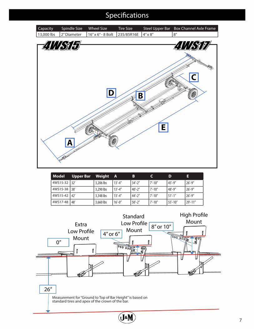
Capacity Spindle Size Wheel Size Tire Size Steel Upper Bar Box Channel Axle Frame13,000 lbs 2” Diameter 16” x 6” - 8 Bolt 235/85R16E 4” x 8” 8”
Model Upper Bar Weight A B C D E4WS15-32 32’ 3,206 lbs 13’-4” 34’-2” 7’-10” 45’-9” 26’-9”4WS15-38 38’ 3,290 lbs 13’-4” 40’-2” 7’-10” 48’-9” 26’-9”4WS15-42 42’ 3,348 lbs 13’-4” 44’-2” 7’-10” 51’-1” 26’-9”4WS17-48 48’ 3,660 lbs 16’-0” 50’-2” 7’-10” 55’-10” 29’-11”
A
D B
E
C
Extra low pro mount weldment for 4” x 6” tube 4-1/2” lip
Low pro base weldment for 4“ x 6” tube and upper mount with 4-1/2” lip
High pro base weldment for 4” x 6” tube and upper mount with 4-1/2” lip
26”
0”4” or 6”
8” or 10”
High Pro�leMount
Standard Low Pro�le
MountExtra
Low Pro�leMount
Measurement for “Ground to Top of Bar Height” is based on standard tires and apex of the crown of the bar.
4-Wheel Steer Mount Options

8
Decals
1
2
3
4
4
5
67
8
2
ATTENTION! BECOME ALERT! YOUR SAFETY IS INVOLVED! Replace Immediately If Damaged or Missing
Description Part No.1 Caution - Keep Lug Nut Tight / Do Not Exceed Load Limit - Decal JM00192202 J&M Oval Decal (Small) 3-5/8” x 5-1/4” JM00151503 HT - Knee Brace Set Up Decal JM00261144 Warning - Fasten Header Securely To Transport Before Moving Decal JM00393815 4WS15 Decal JM00393795 4WS17 Decal JM00393806 Amber Reflective Decal 2” x 9” JM00099467 Red Reflective Decal 2” x 9” JM00099458 Orange Reflective Decal 2” x 9” JM0009944

9
Bolt Torque Specifications
TIGHTENING WHEEL NUTS: Torque 9/16”-18 lug nuts on wheels to 170 ft-lbs during initial operation of the header wagon. Check for proper torque after every 10 hours of use. Failure to do so may damage wheel nut seats. Once seats are damaged it will become impossible to keep nuts tight.
Always tighten hardware to these values unless a different torque or tightening procedure is listed for specific application. Fasteners must always be replaced with the same grade as specified in the manual parts list. Always use the proper tool for tightening hardware. Make sure fastener threads are clean and you start thread engagement properly. Use these values when tightening all bolts and nuts with the exception of wheel nuts.
Stud and Wheel Nut Torque Specifications
Stud Tightening Torque1/2”-20 80 ft-lbs9/16”-18 170 ft-lbs5/8”-18 350 ft-lbs3/4”-16 400 ft-lbs20mm 475 ft-lbs22mm 640 ft-lbs
Always tighten hardware to these values unless a different torque or tightening procedure is listed for specific application. Fasteners must always be replaced with the same grade as specified in the manual parts list. Always use the proper tool for tightening hardware. Make sure fastener threads are clean and you start thread engagement properly. Use these values when tightening all studs and wheel nuts.
SAE FastenersCoarse Thread Series
Grade 5 Grade 8Diameter and Pitch (Inches) Dry Oiled Dry Oiled1/4”-20 8 ft-lbs 6 ft-lbs 12 ft-lbs 9 ft-lbs5/16”-18 17 13 25 183/8”-16 31 23 44 337/16”-14 49 37 70 521/2”-13 75 57 106 809/16”-12 109 82 154 1155/8”-11 150 113 212 1593/4”-10 267 200 376 2827/8”-9 429 322 606 4551”-8 644 483 909 681
Fine Thread SeriesDiameter and Pitch (Inches) Dry Oiled Dry Oiled1/4”-28 10 ft-lbs 7 ft-lbs 14 ft-lbs 10 ft-lbs5/16”-24 19 15 27 203/8”-24 35 26 49 377/16”-20 55 41 78 581/2”-20 85 64 120 909/16”-18 121 91 171 1285/8”-18 170 127 240 1803/4”-16 297 223 420 3157/8”-14 474 355 669 502

10
Operations/Maintenance
DANGER: BE CERTAIN THAT ALL POWER IS SHUT OFF BEFORE SERVICING THE 4 WHEEL STEER HEADER TRANSPORT.
Before the Header Transport is Put into Service:• Has the Slow-Moving Vehicle sign been properly positioned at the rear of the header transport?• Have all danger, warning, caution and important signs on the equipment been read and understood? If employees or others use or
are near this equipment, make sure that they also have read and understood all danger, warning, caution and important signs on the equipment and have also read the operator’s manual.
• Are all braces, bolts, nuts, studs and lug nuts properly fastened?• Has the header transport been properly fastened to the towing unit? Use a good quality hitch pin with clip and safety chains.• Are the rear amber extremity lights properly positioned? Extend lights within 16” of the left and right extremities of the header.• Check alignment of tires yearly. Adjust the push pull rod to realign the tires if needed.
Safety Chain User Instructions• Secure the safety chain by looping it around the tongue support located on the underside of the hitch tongue and connect to the
towing machine’s attaching bar.• Do not allow more slack than necessary for articulation.• Do not use an intermediate support as the attaching point.• Store the safety chain by securing it around the tongue.• Replace the safety chain if one or more links or end fittings are broken, stretched or otherwise damaged or deformed.
Operating Instructions/Maintenance• Adjust the brackets on the header transport to best fit your make and model header.
Note: When mounting the header, NEVER position yourself under or near the header. Securely fasten the header to the header transport.
• Do not exceed the load and size limits of the unit.• Keep the tires properly inflated. Both under inflation and over inflation can greatly reduce tire life. Inflate 235-85 R16 tires to 80 psi.• Inspect bracing and welds periodically and repair immediately, if needed. Failure to repair could cause extensive damage and
greatly reduce the life of the unit.• Repack the bearings in the hub assembly once a year or as needed. Use a good quality LS EP2 severe duty, high shock load, lithium-
based grease.• Check the wheel nuts often and keep them properly tightened.
WARNING: Check safety chains for broken, stretched or damaged link or end fittings. Replace chains if found to be damaged. Do not weld safety chains.
Braking System Requirements• Stopping distance increases with speed and weight of towed loads and on slopes. Towed loads with or without brakes that are too
heavy for the tractor or are towed too fast can cause loss of control. Consider the total weight of the equipment and its load. Note: Observe these recommended maximum road speeds, or local speed limits which may be lower.
• If towed equipment does not have brakes, do not travel more than 20 mph (32 km/h) and do not tow loads more than 1.5 times the tractor weight.
• If towed equipment does have brakes, do not travel more than 25 mph (40 km/h) and do not tow loads more than 4.5 times the trac-tor weight.
• Ensure the load does not exceed the recommended weight ratio. Use additional caution when towing loads under adverse surface conditions, when turning, and on inclines.
DANGER: Tow loads safely.

11
Operations/MaintenanceAdjusting Push-Pull Rod to Align Front and Rear Axles Before initial operation of header transport, follow these steps to align front and rear wheels while under load:1. With the transport empty, loosen both nuts on the push-pull rod. The push-pull rod is left hand threaded on one end and right hand
threaded on the other end to adjust alignment like a turnbuckle. One of the nuts is pictured in blue in the diagram below.2. Place combine header on transport.3. Drive the loaded transport in a straight line on level ground to check alignment.4. Adjust push-pull rod by rotating the main rod body.5. Repeat steps 3 and 4 until the transport rear wheels are aligned with front wheels.6. Remove combine header from transport.7. With the transport empty, tighten both nuts on the push-pull rod.8. Return the combine header to the transport.9. With the nuts on the push-pull rod tightened, drive loaded transport in a straight line on level ground to confirm alignment.

12
DANGER: BE CERTAIN THAT ALL POWER IS SHUT OFF BEFORE SERVICING THE 4 WHEEL STEER HEADER TRANSPORT.
Hub Removal:• Elevate and support the trailer unit carefully.• Remove the wheel.• Remove the grease cap by carefully prying pregressively around the flange ofthe cap.• Remove the cotter pin from the spindle nut or, in the case of E-Z Lube versions, bend the locking tang to the free position. For E-Z
Lube axles produced after February 2002, a new type of retainer is used. Gently pry off retainer from the nut and set aside.• Unscrew the spindle nut (counterclockwise) and remove the spindle washer.• Remove the hub from the spindle, being careful not to allow the outer bearing cone to fall out. The inner bearing cone will be re-
tained by the seal. • For 7,200 lb. and 8,000 lb. axles, a hub puller should be used to assist in drum removal.
Bearing Lubriation:Along with bearing adjustment, proper lubricatino is essential to the proper function and reliability of your trailer axle. Bearings should be lubricated every 12 months or 12,000 miles. The method to repack bearing cones is as follows:• Place a quantity of grease into the palm of your hand.• Press a section of the widest end of the bearing into the outer edge of the grease pile closest to the thumb forcing grease into the
interior of the bearing.• Repeat this while rotating the bearing from roller to roller.• Continue this process until you have the entire bearing completely filled with grease.• Before reinstalling, apply a light coat of grease on the bearing cup.Use a good quality LS EP2 severe duty, high shock load, lithium-based grease.
Bearing Adjustment and Hub Replacement:If the hub has been removed or bearing adjustmennt is required, the following adjustmnet precedure must be followed:• After placing the hub, bearings, washers, and spindle nut back on the axle spindle in reverse order as detailed in the previous
section on hub removal, rotate the hub assembly slowly while tightening the sprindle nut to approximately 50 ft-lbs (12” wrench or pliers with full hand force).
• Then loosen the spindle nut to remove the torque. Do NOT retate the hub.• Fingle tighten the spindle nut until just snug.• Back the spindle nut out slightly until the first castellatin lines up with the cotter key hole and insert the cotter pin (or looking toang
in the case of E-Z Lube).• Bend over the cotter pin legs to secure the nut (or locking tang in the case of E-Z Lube).• Nut should be free to move with only restaint being the cotter pin (or locking tang).
For axles using the new nut retainer:• Finger tighten the nut until just snug, align the retainer to the machined flat on the spindle and press the retainer onto the nut. The
retainer should snap into place. Once in place the retainer/nut assembly should be free to move slightly.• If the nut is too tight, remove the retainer and back the nut off spproximately one twelfth of a turn and reinstall the retainer. The nut
should now be free to move slightly.• Reinstall grease cap.
E-Z Lube Lubrication:• Remove the rubber plug from the end of the grease cap.• Place a standard grease gun onto the grease fitting located in the end of the spindle. Make sure the grease gun nozzle is fully
engaged on the fitting.• Pump grease into the fitting. The old displaced grease will begin to flow back out the cap around the grease gun nozzle.• When the new clean grease is observed, remove the grease gun, wipre off any excess, and replace the rubber plug in the cap.• Rotate hub or drum while adding grease.
Hub and Bearing Maintenance

13
Set-Up InstructionsMounting the Front and Rear axles• Set both of the bottom frame bars on two sawhorses or blocks.NOTE: Place 4” blocks under the small lower bar so the ends are level. The small lower bar is the bar without the truss picutured below.
• Attach the front and rear axle to the frame bars using (8) 5/8” x 6” hex bolts, (8) 5/8” centerlock hex nuts and (2) frame tube end plates. Tighten all hex nuts.

14
Set-Up InstructionsInstalling Tires• Attach the four wheels. Use (8) 9-16” - 18 lug nuts to install the tires. Tighten lug nuts in a star pattern.
1
2
5
3
86
4
7
Prepping for the 4-wheel Steer Tie Rod• Measure from the frame tube to the center of each tire of the back of the unit and adjust the tires so that both sides measure equal
distance. Repeat for the front end. NOTE: Once the tires are adjusted, DO NOT MOVE them.
Front
Rear

15
Set-Up InstructionsInstall the Tie Rod• Before installing the tie rod, slide the two center support brackets pictured below onto the bar. Slide the larger brace towards the
rear of the header transport and the smaller brace towards the front. Insert the guide blocks and secure using the original hardware. While inserting the guide blocks, ensure all holes line up. The guide blocks are two different parts and must line up correctly.
• Adjust both clevis ends so that the holes in the clevis ends line up with the holes in the hitch top plate. • Use (2) 3/4” shoulder bolts and (2) 3/4” shoulder bolt nuts to attach both ends of the push pull rod.
Fig. 5
Install the Center Support Brackets• Place the upper bar center support brackets on the header transport. The small bracket will straddle the support in the middle of the
header transport (as shown below). Place the large bracket on the corresponding bar so they are aligned. Put the 1/2”-13 x 5” hex bolts and 1/2”-13 centerlock hex nuts into place and leaving loose until the next step.

16
Set-Up Instructions
Tie Rod Support Brackets • Secure the tie rod support brackets to the rear of the upper bar center support brace using 3/8”-16 x 1” SF hex bolts and 3/8”-16 SF
hex nuts. Before tightening nuts, push bracket up so that the guide blocks support the tie rod to remove sag in the tie rod.
Center Support Brace • Bolt the center support brace to both support brackets using 3/4”-10 x 6” hex bolts and 3/4”-10 nylon locking hex nuts. Ensure the
center support brace is attached with the holes for the guide blocks facing the rear of the header transport. Tighten the 1/2”-13 hardware used in the previous step.

17
Set-Up Instructions
Install Both Ratchet Strap Weldments • Position both ratchet strap weldments to hold your header from moving in transit using (2) 1/2” x 5” hex head bolts and (2) 1/2”
centerlock hex nuts.
Install the Adjustable Support Arms • Use (4) 3/4” x 9-1/2” pins to attach the adjustable header mount to the frame. Install the 3/4” pins from the front. Secure the pins
using 3/4” cotter pins. Repeat this procedure for the front, rear, and middle adjustable support arms.
Fig. 7

18
Set-Up InstructionsInstall the Header Mounts• Set the mount on the truss bar. Run the 5/8” x 6-1/2” carriage bolt through the bottom of the bottom header mount.
NOTE: The tab on the lower header mount will point away from the center of the frame.• Place the bottom header mount bolt coupler between the ends of the clamp handle assembly. Next, place the washer against the
mount. Line up the holes on the washer and mount bolt coupler and thread the carriage bolt onto the coupler.• Install the upper header mount bracket to the bottom header mount. Attach the header position gusset using (2) 3/4” L Pins (10-
9/32” length). Secure the L pins with (2) 3/4” cotter pins.
Lower Header Mount Tab

19
Set-Up InstructionsAttach the Tongue to the Header Transport • Attach the outer tongue weldment to the front axle using a 6-1/2” x 1-1/4” king pin weldment and 1-1/4” hex nut. • Hook both tongue springs to the axle. • Remove the J-bolts by loosening the and removing the SF nuts positioned toward the front of the tongue. Once removed, hook the
(2) 1/2” J-bolts over the springs and re-insert them to their original holes. Tighten the SF nuts.

20
Set-Up InstructionsInstall the Upper Bar • Using (3) upper bar clamps and (6) 1/2” SF hex nuts attach the upper bar to the upper bar support mounts.
Install the Extension Bracket • Attach the extension bracket to the upper bar using (4) 1/2” x 7” hex bolts and (4) 1/2” centerlock hex nuts.

21
Set-Up InstructionsInstall the Light Bar• Mount the light bar to the extension bracket using (4) 1/2” x 2” hex bolts, (4) damping mounts, and (8) 1/2” centerlock hex nuts.• Mount the SMV sign using the mounting bracket, (2) 1/4” x 3/4” hex bolts, (2) washers, and (2) 1/4” centerlock hex nuts.
Adjusting Light Bar • If needed, adjust the width of the light bar by loosening the light bar adjustment handle and pull out or push in the bar to the
desired width. Retighten the adjustment handle when finished.
Light Bar Adjustment Handle
22
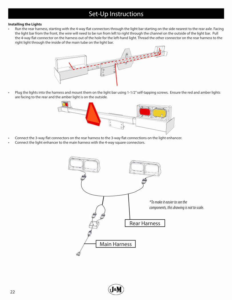
Set-Up InstructionsInstalling the Lights• Run the rear harness, starting with the 4-way flat connectors through the light bar starting on the side nearest to the rear axle. Facing
the light bar from the front, the wire will need to be run from left to right through the channel on the outside of the light bar. Pull the 4-way flat connector on the harness out of the hole for the left-hand light. Thread the other connector on the rear harness to the right light through the inside of the main tube on the light bar.
• Plug the lights into the harness and mount them on the light bar using 1-1/2” self-tapping screws. Ensure the red and amber lights are facing to the rear and the amber light is on the outside.
• Connect the 3-way flat connectors on the rear harness to the 3-way flat connections on the light enhancer. • Connect the light enhancer to the main harness with the 4-way square connectors.
Main Harness
Rear Harness
*To make it easier to see the components, this drawing is not to scale.

23
Set-Up Instructions• Run the 3 male 1 female flat connector on the main harness to the front of the 4WS through the upper bar. There is a hole for the
wire to come out of the bottom of the upper bar near the front of the wagon. Now run it through the front axle from the bottom rear left-hand side to the middle front hole and down the tongue to the cord wrap. During transportation plug the 4-way flat connector on the main harness to the towing vehicle and wrap the remaining cord around the cord wrap.
Installing Optional BrakesNOTE: If there is not a hole in the upper bar behind the rear support arm, cut a 1-3/4” diameter hole in the bottom of the upper bar. Cut the hole 2” behind the rear support arm.• Run the brake wiring harness through the center and out the left hole of the front running gear. • Connect the left front brake and run the two rear connections up the support arm and through the upper bar. • Drill two holes in support arm and secure brake harness using (2) zip ties.• Run the right side connector through the axle and out the right side hole. Connect the front right brake.• Run the brake harness down the rear support arm, drill (2) holes and secure with zip ties. • Run the harness through the center hole and pull one connector through each of the left and right holes. • Connect the rear brakes.
Hole
Hole
Hole

24
Axles
1
32
9
6
45
87
17161513 14
11
10
12
3
18
20
19
Description Part No.1 Right Spindle Assembly (4WS) JM00031872 Front Hitch Weldment (4WS) JM00155763 1-1/4”-12 PN Gr2 Hex Jam Nut JM00016064 4WS Front Axle Assembly JM00155575 1-3/4” ID Bronze Bushing (2” OD x 1” Length) (EB-134) JM00022446 1-3/4” x 14-1/4” King Pin Weldment JM00031807 Left Spindle Assembly (4WS) JM00031708 1-3/4”-12 Z Gr2 Hex Jam Nut JM00097529 11-1/2” x 1-1/4” King Pin Weldment (TB-610) JM000303810 Nut for 5/8” Shoulder Bolt JM000318511 5/8” ID x 3/4” OD x 1/2” Bronze Bushing (BB-58) JM000318912 5/8” Shoulder Dia x 1” Shoulder Length x 1/2”-13 Shoulder Bolt and Nut (SB-58) JM000240813 6-10 Ton Clevis Weldment (Left) (TRE-78L) JM000316814 7/8”-14 Gr5 Z LH Hex Nut JM002768615 Tie Rod (7/8” x 26”) (4WS) (10 Ton) JM000318816 7/8”-14 Gr5 Z Hex Nut JM002571417 6-10 Ton Clevis Weldment (Right) (TRE-78R) JM003014918 Rear Axle Assembly (4WS) JM000316619 1-1/4” x 15-1/8” King Pin Weldment (4WS) JM000316520 Rear Hitch Weldment (4WS) JM0003164

25
7k Idler Hub and Wheel
12
1 2
8 9 10 11
43 65 7
1513 14
Description Part No.1 Seal 18823 (Type A) for G783 JM00032232 Tapered Bearing Cone 25580, 12 Ton JM00181043 14125A Roller Bearing JM00395424 1” USS Flat Washer JM00030635 1”-14 Gr2 Z Castle Hex Nut JM00021396 Cotter Pin (for 1” x 3-2/5” Clevis Pin) JM00030647 Grease Cap (Solid) for 1530290.9 8-6.5” Hub (4WS 170052) JM00587508 Cup, Large Inner, 12 Ton, 25520 JM00181029 Stud 9/16”-18 x 2-13/16” JM002062510 9/16”-18 Conical Lugnut (4WS) (ST) JM000852511 Bearing Cup for Superior Gearbox (14-20”) (414276) JM002507712 7K Idler Hub with studs, nuts & races JM005874313 235-85-R16 Load Range E - 8 Bolt Tire JM000323214 Wheel Rim, 8 Hole, 16” x 6” (16x6-8) JM000323315 Wheel & Tire (235-85-R16 Load Range E - 8 Bolt Tire and 16x6-8 Hole Wheel Rim) JM0009977

26
61
3
2
54
7
Description Part No.1 Upper Bar Slide Mount (UBSM-3) JM00151332 3/4” x 8” Z L Pin (Header Wagon, c450) JM00297383 Upper Bar Support Arm (UBSA-3) JM00030774 Upper Bar Clamp (4x8) (UBC-3) JM00030815 1/2”-13 Gr5 Z SF Hex Nut JM00021536 3/16” x 2-1/2” Hair Clip Pin (316HP) JM00016577 Lifting Arm - 60” Hole Spread (4WS) JM0003078
Lifting Arms Ends
Brakes for 7k Axles
1
Description Part No.1 7K Brake Drum Assembly Left Hand JM00359732 7K Brake Drum Assembly Right Hand JM0035974

27
Lifting Arms Middle
5
21
7
9
6
34
8
16
10
12
1413
11
15
17
Description Part No.1 Back Center Leg Mount (4WS) JM00545822 3/4”-10 Gr2 Z Nylon Locking Hex Nut JM00267563 Middle Support Leg Cross Support (4WS) JM00545784 Front Center Leg Pivot Mount (4WS) JM00545765 1/2” -13 x 5” Gr5 Z Hex Bolt JM00016216 3/4”-10 x 6” Gr5 Z Hex Bolt JM00166837 1/2”-13 Gr2 Z Centerlock Hex Nut JM00015118 3/4” x 8” Z L Pin (Header Wagon, c450) JM00297389 3/16” x 2-1/2” Hair Clip Pin (316HP) JM000165710 1/4”-20 x 2” Gr5 Z Hex Bolt JM000159111 1” Wide UHMW Small Guide Block (1-1/2” Tall) (4WS) JM001458312 Center Slide Brace, Small Flat Plate JM005508113 1” Wide UHMW Large Guide Block (2” Tall) (4WS) JM001458414 1/4”-20 Gr2 Z Nylon Locking Hex Nut JM000215915 Center Slide Brace, Large Flat Plate JM005507916 3/8”-16 Gr5 Z SF Hex Nut JM000215217 3/8”-16 x 1” Gr5 Z SF Hex Bolt JM0002092

28
Header Mount and Tie Down Straps
10
12
14
13
11
15
16
56
7
8
3
4
9
1
2
Description Part No.1 Upper Header Wagon Mount JM00143512 Removable Header Stop Gusset JM00030753 3/16” x 2-1/2” Hair Clip Pin (316HP) JM00016574 Low Profile Bottom Mount Weldment 4” x 6” (Front) JM00377185 5/8”-11 x 6-1/2” Gr5 Z Carriage Bolt JM00016516 3/4” L Pin (10-9/32” Length) JM00030767 5/8” USS Flat Washer JM00030738 Header Saddle Mount Bolt (Coupler) JM00016539 Clamp Handle Assembly (CHA2) JM000165610 1/2”-13 Gr2 Z Centerlock Hex Nut JM000151111 1/2”-13 x 5” Gr5 Z Hex Bolt JM000159412 Ratchet Strap Bracket (60 Degree) (HT974, 4WS) JM000231413 3/8”-16 Gr2 Z Centerlock Hex Nut JM000151214 3/8” ID, 1” OD Z Flat Washer JM000306115 2” Tie-down Ratchet (10,000 lb) (RA-1) JM000308416 3/8”-16 x 1” Gr8 YZ Hex Bolt JM000148517 Extra Low Profile Mount 4” x 6” Saddle (Front) JM004621018 Extra Low Profile Mount 4” x 6” Saddle (Back) JM002894819 Low Profile Bottom Mount Weldment 4” x 6” (Back) JM000307220 High Profile Bottom Mount Weldment 4” x 6” (Front) JM003257321 High Profile Bottom Mount Weldment 4” x 6” (Back) JM0007140
212019
1
4
1817
29
Upper Bar, Frame, 4WS Rod, and Connections
21 3 4
5 6 87
11
10
13
14
12
9
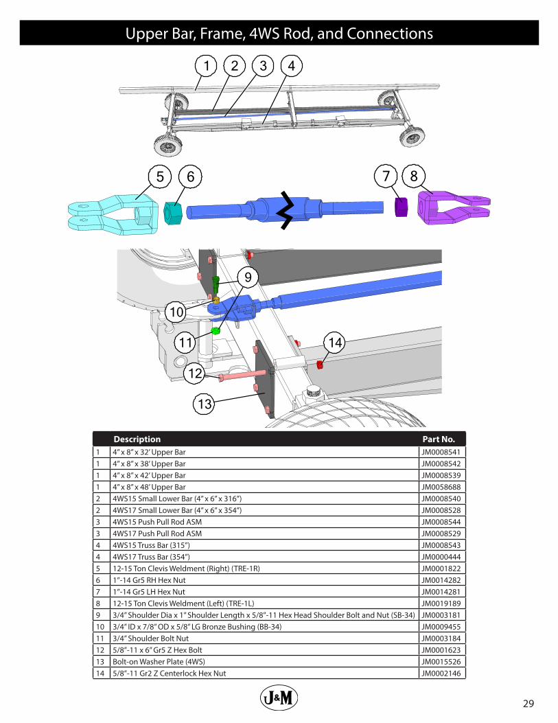
Description Part No.1 4” x 8” x 32’ Upper Bar JM00085411 4” x 8” x 38’ Upper Bar JM00085421 4” x 8” x 42’ Upper Bar JM00085391 4” x 8” x 48’ Upper Bar JM00586882 4WS15 Small Lower Bar (4” x 6” x 316”) JM00085402 4WS17 Small Lower Bar (4” x 6” x 354”) JM00085283 4WS15 Push Pull Rod ASM JM00085443 4WS17 Push Pull Rod ASM JM00085294 4WS15 Truss Bar (315”) JM00085434 4WS17 Truss Bar (354”) JM00004445 12-15 Ton Clevis Weldment (Right) (TRE-1R) JM00018226 1”-14 Gr5 RH Hex Nut JM00142827 1”-14 Gr5 LH Hex Nut JM00142818 12-15 Ton Clevis Weldment (Left) (TRE-1L) JM00191899 3/4” Shoulder Dia x 1” Shoulder Length x 5/8”-11 Hex Head Shoulder Bolt and Nut (SB-34) JM000318110 3/4” ID x 7/8” OD x 5/8” LG Bronze Bushing (BB-34) JM000945511 3/4” Shoulder Bolt Nut JM000318412 5/8”-11 x 6” Gr5 Z Hex Bolt JM000162313 Bolt-on Washer Plate (4WS) JM001552614 5/8”-11 Gr2 Z Centerlock Hex Nut JM0002146
30
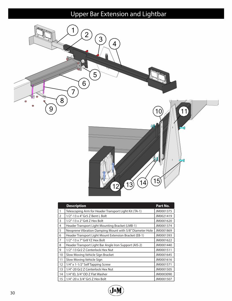
Upper Bar Extension and Lightbar
12
3
56
98
7
4
1413
11
15
10
12
Description Part No.1 Telescoping Arm for Header Transport Light Kit (TA-1) JM00013752 1/2”-13 x 4” Gr5 Z Bent L Bolt JM00214193 1/2”-13 x 2” Gr8 Z Hex Bolt JM00016204 Header Transport Light Mounting Bracket (LMB-1) JM00013745 Neoprene Vibration Damping Mount with 5/8” Diameter Hole JM00018696 Header Transport Light Mount Extension Bracket (EB-1) JM00013937 1/2”-13 x 7” Gr8 YZ Hex Bolt JM00016228 Header Transport Light Bar Angle Iron Support (AIS-2) JM00014409 1/2”-13 Gr2 Z Centerlock Hex Nut JM000151110 Slow Moving Vehicle Sign Bracket JM000164511 Slow Moving Vehicle Sign JM000161612 1/4” x 1-1/2” Self Tapping Screw JM000157113 1/4”-20 Gr2 Z Centerlock Hex Nut JM000150514 1/4” ID, 3/4” OD Z Flat Washer JM000309015 1/4”-20 x 3/4” Gr5 Z Hex Bolt JM0001507

31
Tongue
67
5
1112
43
98
10
21
16
1718
1514
13
Description Part No.1 Short Inner Tongue (40”) (Header Transport) JM00016832 Compression Spring (1” x 1-3/4”) for Door Assembly & Tongue Latch JM00016883 Tongue Latch (Flapper Weldment) 10 Ton JM00030334 12’ Outer Tongue Weldment (4WS15) JM0015676*4 14’10” Outer Tongue Weldment (AWS17) JM0003041*5 1-1/2” ID x 3/8” Wall GW x 1-3/4” GD Rubber Grommet (GR-134) JM00008306 Wire Harness Storage Bracket (WHB-1) JM00014387 1/4” x 1-1/2” Self Tapping Screw JM00015718 Spacer Blocks, 2-1/2”, 6-15 Ton (SB-212) JM00030329 17/64” x 1-3/4” Z Roll Pin JM000165210 1” x 5-3/4” Flapper Pivot Shaft - Case Hardened and Zinced (LS-610) JM002773211 7/8”-9 x 2” Gr5 Z Hex Bolt JM000210812 Tongue Stop Bolt Ring JM000164913 1/2”-13 Gr5 Z SF Hex Nut JM000215314 1/2”-13 x 6” Gr5 Z J-Bolt JM000216815 Large Tongue Spring (1-3/4” x 12-1/2”) (TS-615H) JM001420016 6-1/2” x 1-1/4” King Pin Weldment (TB-1082) JM000303617 1-1/4” ID x 2-1/2” OD x 1/8” Z Flat Washer JM002032218 1-1/4”-12 PN Gr2 Hex Jam Nut JM0001606

32
Lights and Wiring
Description Part No.1 Right LED Light Assembly - Header Transport JM00016822 Left LED Light Assembly - Header Transport JM00016803 Rear Harness (4WS) JM00071664 Light Enhancer (4WS) JM00074455 Main Harness (4WS) JM0007436
3
4
5
1 2
*To make it easier to see the components, this drawing is not to scale.
Spare Tire Mount
Description Part No.1 4WS Spare Tire Mount Weldment JM00502832 9/16” x 2-1/4” Stud JM00375023 9/16”-18 Conical Lugnut (4WS) (ST) JM0008525
1 2 3