Embed Size (px)
Citation preview

© 2002by Bosch Rexroth AG, Industrial Hydraulics, D-97813 Lohr am Main
All rights reserved. No part of this document may be reproduced or stored, processed, duplicated or circulated usingelectronic systems, in any form or by any means, without the prior written authorisation of Bosch Rexroth AG.In the event of contravention of the above provisions, the contravening party is obliged to pay compensation.
This document was prepared with the greatest of care, and all statements have been examined for correctness.This document is subject to alterations for reason of the continuing further developments of products.No liability can be accepted for any incorrect or incomplete statements.
4WS.2E… 1/16 RE 29 591/06.02
Overview of contents
Contents Page
Features 1
Ordering details, preferred types 2 and 3
Symbols 3
Test unit 3
Function, section 4 and 5
Technical data 6 and 7
Control electronics 7
Plug-in connectors, electrical connections 8
Characteristic curves 9 to 13
Unit dimensions, subplates 14 and 15
Pilot oil supply and drain, flushing 16
RE 29 591/06.02
Replaces: 03.93
4-way directional servo valveType 4WS.2E…
Nominal size 16Series 2XMaximum operating pressure 210/315 barMaximum flow 320 L/min
Type 4WSE2ED 16-2X/…B… with mechanical and electricalfeedback and integrated control electronics
H/A
3013
Features
– Valve for closed loop position, force and speed control
– Two stage servo valve with mechanical or mechanical andelectrical feedback
– 1st stage as an orifice-flapper plate amplifier
– For subplate mounting, porting pattern to DIN 24 340 form A16with port X, subplates to catalogue sheet RE 45 054 (separateorder)
– Dry torque motor, no contamination of the solenoid gap by thepressure fluid
– Can also be used as a 3-way version
– Wear-free spool return element
– Three control variations
– Control:• External control electronics in eurocard format (separate
order), see page 7• Or with the control electronics integrated into the valve
– The valves with integrated control electronics are calibrated andtested
– The pilot oil supply, internal/external, can be changed withoutdismantling the valve
– The control sleeve can be replaced
– Filter for the 1st stage is accessible from the outside by meansof a plug
Type 4WS2EM 16-2X/…B… with mechanical feedback andassociated external control electronics (separate order)
H/A/
3012

RE 29 591/06.02 2/16 4WS.2E…
1
2
3
7
6
5
4
2
1
3
4
5
6
7
Input pressure rangeThe system pressure must be maintained as constant as possible.
Pilot pressure range: 10 to 210 bar or 10 to 315 bar
With referance to the dynamics, within the permissible pressure rangethe frequency relationship must be taken into account.
Spool overlap
The spool overlap in % refers to the control spool nominal stroke.
Other spool overlaps on request!
Seal material
If other seal materials are required please consult us!
Details in clear text
Special requirments are to be specified in clear text. After receipt ofthe order they will be checked by the factory and the type code willbe completed with an associated number.
Electrically operated2-stage4-way servo valve
For external = 4WS2Econtrol electronics
With integrated = 4WSE2Econtrol electronics
Mechanical feedback = M
Mechanical and = Delectrical feedback(only with integrated electronics)
Nominal size 16 = 16
Series 20 to 29 = 2X(20 to 29: unchanged installation and connection dimensions)
Nominal flowAt a valve pressure differential ∆p = 70 bar100 L/min = 100150 L/min = 150200 L/min = 200(the tolerance of the flow/signal functionon page 9 has to be taken into account!)
Coil or control dataValves for external control electronicsCoil No. 12 (50 mA/85 Ω per coil) = 12Valves with integrated electronicsControl: Command value ± 10 mA/1 kΩ = 8
Command value ± 10 V/≥ 50 kΩ = 9
Further detailsin clear text
V = FKM seals
Spool overlap
E = 0 to 0.5 % negative
Electrical connectionValve for external control electronics:
K8 = Without plug-in connectorwith component plug for a 4-pinplug-in connector to VG 095 342
Valve with integrated control electronics:K9 = Without plug-in connector
with component plug for a 6-pinplug-in connector to E DIN 43 563-AM6-3
Plug-in connector – separate order
Input pressure range for the 1st stage
210 = 10 to 210 bar315 = 10 to 315 bar
Pilot oil supply and drainET = Internal supply and drain (standard)T = External supply, internal drain
16 –2X / B E V *
Nominal flowThe nominal flow refers to a 100 % command value signal at a 70bar valve pressure differential (35 bar per control land). This valvepressure differential is to be considered as a reference value. Othervalues cause a change in the flow.Please take into account a possible nominal flow tolerance of± 10 % (see flow/load function on page 9).
Electrical control dataValves for external control electronics: The positioning signal mustbe generated by a current regulated output stage. See page 7 forservo amplifiers.Valves with integrated control electronics: The command value canbe applied as a voltage (ordering detail „9“) or for longer distances(> 25 m between the control and the valve) as a current (orderingdetail „8“).
Input pressure for the pilot controlThe pilot pressure must be maintained as constant as possible.Therefore an external pilot control via port X is often advantageous.
The dynamic response of the valve may be influenced using a higherpressure at X than at P.
Ordering details

4WS.2E… 3/16 RE 29 591/06.02
A
P T
a, b
B
a, b
BA
P T
a, b
BA
P T
A
P T
a, b
B
Test unit (battery operated, optionally with a power supply) tocatalogue sheet RE 29 681Attention:– Only for valves with external control electronics
Test unit for proportional and servo valves with integratedcontrol electronicsType VT-VET-1, series 1X to catalogue sheet RE 29 685.
The test unit is used for the control and functional testing of propor-tional and servo valves with integrated electronics. It is suitable fortesting valves with an operating voltage of ± 15 V or 24 V.The following operating modes are possible:– External operation → Linking the operating voltage and the
command value from the control cabinet to the valve– Internal/external operation → Command value is applied by the
test unit; the operating voltage via the control cabinet– Internal operation → Operating voltage via a seperate power
supply; the command value is applied by the test unit– Command value is applied via a BNC socket → Optional operating
voltage
Symbols
Mechanical feedback Electrical and mechanical feedback
Valves with integrated control electronicsValves for external control electronics
Preferred types (readily available)
Valves for external control electronics,mechanical feedback
Material No. Type 4WS2EM
00769978 4WS2EM 16-2X/100B12ET315K8EV00716550 4WS2EM 16-2X/150B12ET315K8EV00960575 4WS2EM 16-2X/200B12ET315K8EV
Valves with integrated control electronics,mechanical and electrical feedback
Material No. Type 4WSE2ED00769983 4WSE2ED 16-2X/100B9ET315K9EV00769982 4WSE2ED 16-2X/150B9ET315K9EV00769984 4WSE2ED 16-2X/200B9ET315K9EV
Material No Type 4WSE2EM
00769976 4WSE2EM 16-2X/100B9ET315K9EV00769980 4WSE2EM 16-2X/150B9ET315K9EV00769981 4WSE2EM 16-2X/200B9ET315K9EV
Valves with integrated control electronics,mechanical feedback
Detailed
Simplified
Test unit

RE 29 591/06.02 4/16 4WS.2E…
B PA T X
3
2
1
9
7 8
4
5
6
Function, section
Type 4WS2EM 16 …
4WS(E)2EM 16-2X/...The valve types 4WS(E)2EM... are electrically actuated, 2-stage servodirectional valves with a porting pattern to DIN 24 340 form A16.They are primarily used for the closed loop control of position, forceand velocity.These valves comprise of an electro-mechanical convertor (torquemotor) (1), a hydraulic amplifier (flapper jet principle) (2) and a controlspool (3) in a sleeve (2nd stage), that is connected to the torquemotor via a mechanical feedback.Via an electrical input signal at the coils (4) of the torque motor, aforce is generated via a permanent magnet at the armature (5) that,in conjunction with a torque tube, (6) generates a torque. Due to thisthe flapper plate (7), which is connected with the torque tube (6) viaa rod, is moved out of the central position between the control orifices(8) a pressure differential now results which acts on the front face ofthe control spool. This pressure differential causes the spool to move,whereby the pressure connection is connected to an actuatorconnection and at the same time the other actuator connection isconnected to the return connection.The control spool is connected via a feedback spring (mechanicalfeedback) (9) to the flapper plate and torque motor. The control spoolcontinues to change position until the torque feedback, via thefeedback spring and the electro-magnetic torque of the torque motorare balanced, and the pressure differential at the flapper jet systembecomes zero.The stroke of the control spool and thus the flow through the pilotcontrol valve is closed loop controlled in proportion to the electricalinput signal. It has, however to be taken into account that the flow isdependent on the valve pressure differential.
External control electronics, type 4WS2EM 16-2X/...(separate order)
External control electronics, (servo amplifier), are used to control thevalve, they so amplifiy the analogue input signal (command value)that the controlled current output signal is capable of driving thevalve.
Integrated control electronics, types 4WSE2EM16-2X/... and4WSE2ED 16-2X/...
For the amplification of the analogue input signal control electronics(10), which are specially matched to the valve, are integrated intothe valve. They are built into the torque motor cover plate. The valvezero point can be adjusted by a potentiometer which is externallyaccessible.
4WSE2ED 16-2X/...This type of valve is fitted with, in addition to the mechanical closedloop control via a feedback spring, an electrical spool positionacquisition and control system. The spool position is obtained via aninductive position transducer (11). The position transducer signal iscompared with the command value via the integrated controlelectronics (10). Any possible control deviation is electrically amplifiedand then passed onto the torque motor as a control signal. With theadditional electrical feedback it is possible to obtain higher dynamicvalues in the small signal range than the purely mechanical versiondue to the electrical closed loop amplification. The mechanicalfeedback ensures that, in the case of failure of the electrical powersupply, the spool is positioned in the zero range.The valve is only available with integrated control electronics. Thevalve zero point can be adjusted by an externally accessiblepotentiometer.

4WS.2E… 5/16 RE 29 591/06.02
10
11
B PA T X
B PA T X
10
Type 4WSE2EM 16…
Type 4WSE2ED 16…
Section

RE 29 591/06.02 6/16 4WS.2E…
p
70
Technical data (for applications outside these applications, please consult us!)
General
Porting pattern DIN 24 340 form A16
Installation Optional, it has however to be ensured that, when the system isstarted, the pilot control is supplied with an adequate pressure ( ≥10 bar)!
Storage temperature range °C –20 to +80
Ambient temperature range °C –30 to +70, valve for external control electronics
–20 to +60, valve with integrated control electronics
Weight With mechanical feedback kg 10.0With mechanical and electrical feedback kg 11.0and integrated control electronics
Hydraulic (measured with a viscosity of ν = 32 mm2/s and ϑ = 40 °C)
Operating pressure (ports A, B, P, X) bar 10 to 210 or 10 to 315
Return pressure, port T bar Pressure peaks < 100, static < 10
Pressure fluid Mineral oil (HL, HLP) to DIN 51 524,other pressure fluids on request!
Pressure fluid temperature range °C –20 to +80; preferably +40 to +50
Viscosity range mm2/s 15 to 380; preferably 30 to 45
Degree of contamination Maximum permissible A filter with a minimum retention ratedegree of of βX ≥ 75 is recommended without
contamination of the bypass valve and fitted as close aspressure fluid possible in front of the servo valve
Class 7 x = 5
Zero flow qV,L1) (spool overlap “E”)
measured without a dither signal L/min ≤ • 3.5 L/min 2)
Nominal flow qV nom ± 10 % 3)
at a valve pressure differential ∆p = 70 bar 4) L/min 100 150 200
Pressure gain (spool overlap „E“)at 1% change in stroke (starting from the hyd. zero point) % von p ≥ 65 ≥ 80 ≥ 90
Control spool stroke mm 0.6 0.9 1.2
Control spool area mm2 78
Feedback system Mechanical (M) Mechanical and electrical (D)
Hysteresis (dither optimised) % ≤ 1.5 ≤ 0.5
Reversal range (dither optimised) % ≤ 0.3 ≤ 0.2
Response sensitivity (dither optimised) % ≤ 0.2 ≤ 0.1
Zero balance in % von Inom ≤ 3 ≤ 2
Zero offset at change in:
Pressure fluid temperature %/20 °K ≤ 1.5 ≤ 1.2
Ambient temperature %/20 °K ≤ 1 ≤ 0.5
Operating pressure %/100 bar ≤ 2 ≤ 1
Return pressure 0 to 10 % of p % ≤ 1 ≤ 0.5
1) qV,L = Zero flow in L/min2) p = Operating pressure in bar
3) qV nom = Nominal flow (complete valve) in L/min4) ∆p = Valve pressure differential in bar

4WS.2E… 7/16 RE 29 591/06.02
A DB
60
104SW
20
Ø28
Ø6,
5…Ø
9,5
C
Technical data (for applications outside these parameters, please consult us!)Electrical
Feedback system Mechanical (M) Mechanical and electrical (D)
Valve protection to EN 60 529 IP65
Signal type Analogue
Nominal current per coil mA 50 –
Resistance per coil Ω 85 –
Inductivity at 60 Hz and 100% nominal current:Series circuit H 0.96 –
Parallel circuit H 0.24 –
Recommended The amplitude value is dependent on the hydraulic system:dither signal: f = 400 Hz a max. 5 % vom of the nominal current
Electrical, external control electronics
Amplifier in (separate order) eurocard format Type VT-SR2, to catalogue sheet RE 29 980
Note: For details regarding the environmental simulation test covering EMC (electro-magnetic compatibility), climateand mechanical loading see RE 29 591-U (declaration regarding environmental compatibility).
Coil electrical connections in the component plug (for valves with external control electronics)The electrical connections can be either in parallel or series. Due tooperational safety considerations and the low spool inductivity, werecommend a parallel circuit.
BlueRed
B AC D
4 WS 2 EM 16-2X/...
Parallel circuit: In the plug connect contacts A with B and Cwith D.
Series circuit: In the plug connect contacts B with C.
Electrical control from A (+) to D (–) results in a flow direction fromP to A and B to T. Reversed electrical control results in a flow directionof P to B and A to T.
Connection cable:4-core, 0.75 mm2, screened (e.g. cable type LiYCY 4x0.75mm2)Outside diameter 6.5 to 9.5 mmOnly connect the screen to the supply side.
BlueRed
Plug-in connector
Plug-in connector version K9 to E DIN 43 563-BF6-3/Pg11separate order under Material No. 00223890(metal version)
Plug-in connector version K8 (external control electronics) toVG 095 342 – separate order under Material No. 00002460
AB
CD
E
F
Ø8…
Ø13
,5
85
20A
/F20
A/F

RE 29 591/06.02 8/16 4WS.2E…
Terminal connections 4 WSE2E .16. (valves with integrated control electronics)
Supply voltage: ± 15 V ± 3 %, residual ripple < 1 %
Command value: A command value at plug connection D = negative with respect to the plug connection Eresults in a flow from P to B and A to T.
Measurement output F has a negative signal with respect to .
A command value at plug connection D = positive with respect to the plug connection Eresults in a flow from P to A and B to T.
Measurement output F has a positive signal with respect to .
Measurement output: The voltage signal UF is proportional to the spool stroke.
A
B
C
D
E
F
Re
Ri
Integratedcontrol electronics
1) For valves without electrical feedback terminal F is not connected.
Zero point adjustment
Note: Electrical signals (e. g. actual value) taken via valve electronics must not be used to switch offthe machine safety functions!
(Also see European standard "Safety requirements of fluid technology systems and components– hydraulics", prEN 982 !)
Current Voltageinput signal input signalControl “8” Control “9”
+ 15 V + 15 V– 15 V – 15 V
± 10 mA; ± 10 VRe = 1 kΩ Re ≥ 50 kΩ
Nom. stroke corresponds to approx. ± 10 Vwith respect to ; Ri = 1 kΩ
Max. 150 mA Max. 150 mA
± 10 mA ≤ 0.2 mA
Terminal connections Supply A
voltage B(± 3 %) CCommand value D
E
Measuring output F 1)
for the control spool
Current Aconsumption at Bplug terminal D
E

4WS.2E… 9/16 RE 29 591/06.02
20 40 60 80
–40–60–8020
40
60
80
100
80
60
40
20
100
–20
P B; A T
–100
P A; B T
110
110
100
Characteristic curves (measured with HLP32, ϑ oil = 40 °C ± 5 °C)
Flow/load function (tolerance ± 10 %)
at 100 % command value signal
Tolerance range of flow/signal function
at constant valve pressue differential
Flow
in L
/min
→
Valve pressure differential in bar →
∆p = Valve pressure differential(input pressure minus thereturn pressure and minusthe load pressure)
Flow in %
Command valuein %
Passes through zerodependent on spooloverlap
Typical flowcurve
Tolerance range
500
400
300
200
150
100
70
50
40
30
20
700
1000
10 20 30 50 70 100 200 30015 150
q Vnom = 200
q Vnom = 150
q Vnom = 100
RE 29 591/06.02 10/16 4WS.2E…
0 20 50 60
40
60
80
100
80 10010
20
30 40 70 90 0 20 50 60
40
60
80
100
80 10010
20
30 40 70 90
2 20 50 100–25
–20
–15
–10
–5
0
5
300 700
–150
–120
– 90
– 60
– 30
10– 0
2 20 50 100–25
–20
–15
–10
–5
0
5
300 700
–150
–120
– 90
– 60
– 30
10– 0
0 20
40
60
80
100
10
20
30 40
30
50
70
10
90
5 15 25 35 0 20
40
60
80
100
10
20
30 40
30
50
70
10
90
5 15 25 35
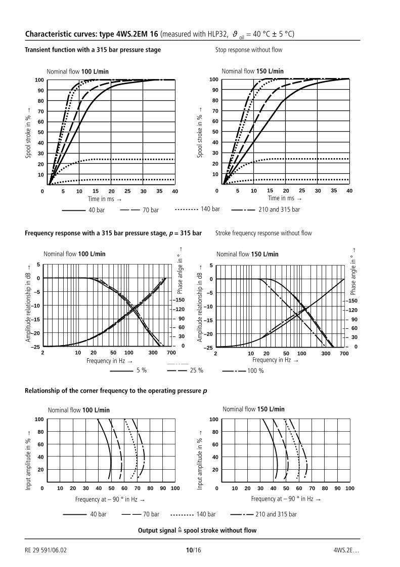
Characteristic curves: type 4WS.2EM 16 (measured with HLP32, ϑ oil = 40 °C ± 5 °C)
Nominal flow 100 L/min Nominal flow 150 L/min
Time in ms →
Spoo
l stro
ke in
%→
40 bar 70 bar 140 bar 210 and 315 bar
Time in ms →Sp
ool s
troke
in %
→
Nominal flow 100 L/min Nominal flow 150 L/min
Frequency in Hz →
Ampl
itude
rela
tions
hip
in d
B→
5 % 25 % 100 %
Phas
e an
lge
in°→
Frequency in Hz →
Ampl
itude
rela
tions
hip
in d
B→
Phas
e an
gle
in°→
Relationship of the corner frequency to the operating pressure p
Nominal flow 100 L/min Nominal flow 150 L/min
Frequency at – 90 ° in Hz →
Inpu
t am
plitu
de in
%→
40 bar 70 bar 140 bar 210 and 315 bar
Frequency at – 90 ° in Hz →
Inpu
t am
plitu
de in
%→
Output signal = spool stroke without flow
Transient function with a 315 bar pressure stage Stop response without flow
Frequency response with a 315 bar pressure stage, p = 315 bar Stroke frequency response without flow
^

4WS.2E… 11/16 RE 29 591/06.02
Characteristic curves: type 4WS.2EM 16 (measured with HLP32, ϑ oil = 40 °C ± 5 °C)
40 bar
70 bar
140 bar
210 and 315 bar
Nominal flow 200 L/min
Spo
ol st
roke
in %
Nominal flow 200 L/min
0 20 50 60
40
60
80
100
80 10010
20
30 40 70 90
40 bar
70 bar
140 bar
210 bar and 315 bar
Frequency in Hz2 20 50 100
–25
–20
–15
–10
–5
0
5
300 700
–150
–120
– 90
– 60
– 30
10– 0
5 %
25 %
100 %
Frequency response with a 315 bar pressure stage, p = 315 bar Stroke requency response without flow
Transient function with a 315 bar pressure stage Step response without flow
Relationship of the corner frequency to the operating pressure p
Phas
ean
gle
in °
Nominal flow 200 L/min
Time in ms
Ampl
itude
rela
tions
hip
in d
BIn
put a
mpl
itude
in %
Frequency at – 90 ° in Hz
0 20
40
60
80
100
10
20
30 40
30
50
70
10
90
5 15 25 35
Output signal = spool stroke without flow^

RE 29 591/06.02 12/16 4WS.2E…
Characteristic curves: type 4WSE2ED 16 (measured with HLP32, ϑ oil = 40 °C ± 5 °C)
Time in ms
Frequency at – 90 ° in Hz
40 bar 70 bar 140 bar 210 bar and 315 bar
Frequency at – 90 ° in Hz0 20 200
20
100
40 60 80 100 120 140 160 180
40
60
80
0 20 200
20
100
40 60 80 100 120 140 160 180
40
60
80
Nominal flow 150 L/minNominal flow 100 L/min
Relationship of the corner frequency to the operating pressure p
Frequency in Hz
5 % 25 % 100 %
2 10 700
-25
-20
-15
-10
-5
0
5
-3020 50 100 300
-300-270-240-210-180-150-120-90-60-30
2 10 700
-25
-20
-15
-10
-5
0
5
-3020 50 100 300
-300-270-240-210-180-150-120-90-60-30
Nominal flow 100 L/min Nominal flow 150 L/min
Frequency response with a 315 bar pressure stage, p = 315 bar Stroke requency response without flow
Time in ms
40 bar 70 bar 140 bar 210 bar and 315 bar
0 5 10 15 20 25 30 35 40
10
110
20
30
40
50
60
70
80
90
100
Nominal flow 150 L/min
Transient function with a 315 bar pressure stage Step response without flow
0 5 10 15 20 25 30 35 40
10
110
20
30
40
50
60
70
80
90
100
Frequency in Hz
Nominal flow 100 L/min
Spoo
l stro
ke in
%
Spoo
l stro
ke in
%
Phas
e an
gle
in °
Pha
se a
ngle
in °
Ampl
itude
rela
tions
hip
in d
B
Ampl
itude
rela
tions
hip
in d
B
Inpu
t am
plitu
de in
%
Inpu
t am
plitu
de in
%
Output signal = spool stroke without flow^

4WS.2E… 13/16 RE 29 591/06.02
Characteristic curves: type 4WSE2ED 16 (measured with HLP32, ϑ oil = 40 °C ± 5 °C)
40 bar
70 bar
140 bar
210 and 315 bar
0 20 200
20
100
40 60 80 100 120 140 160 180
40
60
80
Nominal flow 200 L/min
Frequency in Hz
5 %
25 %
100 %
2 10 700
-25
-20
-15
-10
-5
0
5
-3020 50 100 300
-300-270-240-210-180-150-120-90-60-30
Nominal flow 200 L/min
40 bar
70 bar
140 bar
210 and 315 bar
Time in ms0 5 10 15 20 25 30 35 40
10
110
20
30
40
50
60
70
80
90
100
Spoo
l stro
ke in
%
Phas
e an
gle
in °
Relationship of the corner frequency to the operating pressure p
Transient function with a 315 bar pressure stage Step response without flow
Frequency response with a 315 bar pressure stage, p = 315 bar Stroke frequency response without flow
Nominal flow 200 L/min
Ampl
itude
rela
tions
hip
in d
B
Frequency at – 90 ° in Hz
Inpu
t am
plitu
de in
%
Output signal = spool stroke without flow^

RE 29 591/06.02 14/16 4WS.2E…
0,006/100mm
R 4max
Unit dimensions: type 4WS.2EM 16 (dimensions in mm)
Required surface finish of themating piece
141
91
8523
186
23 Ø 3 3
89
124
15 129 67
53
41 1,5
69,9
71,5
91
10,5 1,
6
34,1
50Ø 6,6
20
101,6Ø 11
Ø 10,5Ø 18
156
A
T P X
B
ca. 70
6 8 9 7 10 2 5
3.13.24 1.1 1.2
6 Name plate
7 Locating pin (2 off)
8 Identical seal rings for ports A, B, P and T
9 Seal ring for port X
10 Porting pattern to DIN 24 340, form A 16
Subplates G 172/01 (G 3/4)
G 174/01 (G 1); G 174/08 (flange)to catalogue sheet RE 45 056 must be ordered separately.
Valve fixing screws are included within the scope of supply.
4 off M10 x 100 DIN 912-10.9; MA = 75 Nm2 off M6 x 100 DIN 912-10.9; MA = 15.5 Nm
1.1 Pilot control (1st stage) without integrated controlelectronics (4 WS 2 EM 16)
1.2 Pilot control (1st stage) with integrated controlelectronics (4 WSE 2 EM 16)Electrical zero point setting:Having removed the plug (2.5A/F) the zeropoint may be corrected via the potentiometer.
2 2nd stage
3.1 Without integrated electronics:4-pin plug-in connector compatible with VG 095 342
3.2 With integrated electronics:6-pin plug-in connector compatible with VG 095 342
4 Space required to remove the plug-in connector, take theconnection cable into account!
5 For setting the hydraulic zero point on both sides5A/F internal hexagon

4WS.2E… 15/16 RE 29 591/06.02
0,006/100mm
R 4max
Required surface finish of themating piece
Unit dimensions: type 4WSE2ED 16 (dimensions in mm)
156
91
85
23
218
55 Ø 3 3
89
124
53
41 1,569
,9
71,5
91
10,5 1,
6
34,1
50Ø 6,6
20
101,6Ø 11
Ø 10,5Ø 18
6
A
T P X
B
15 129 67
ca. 70
6 8 9 7 10
4 3
52
1
1 Pilot control (1st stage) with integrated control electronicsElectrical zero point setting:Having removed the plug (2.5A/F) the zero pont may becorrected via the potentiometer.
2 2nd stage
3 6-pin plug-in connector compatible to VG 095 342
4 Space required to remove the plug-in connector,take the connection cable into account!
5 Setting of hydraulic zero point via two screws5A/F and 3A/F internal hexagon
6 Name plate
7 Locating pin (2 off)
8 Identical seal rings for ports A, B, P and T
9 Seal ring for port X
10 Porting pattern to DIN 24 340, form A 16
Subplates G 172/01 (G 3/4)G 174/01 (G 1); G 174/08 (flange)
to catalogue sheet RE 45 056 must be ordered separately.
Valve fixing screws are included within the scope of supply.
4 off M10 x 100 DIN 912-10.9; MA = 75 Nm2 off M6 x 100 DIN 912-10.9; MA = 15.5 Nm

RE 29 591/draft 16/16 4WS.2E…
Bosch Rexroth AGIndustrial Hydraulics
D-97813 Lohr am MainZum Eisengießer 1 • D-97816 Lohr am MainTelefon 0 93 52 / 18-0Telefax 0 93 52 / 18-23 58 • Telex 6 89 418-0eMail [email protected] www.boschrexroth.de
The data specified above only serve to describethe product. No statements concerning a certaincondition or suitability for a certain applicationcan be derived from our information. It must beremembered that our products are subject to anatural process of wear and ageing.
Bosch Rexroth Limited
Cromwell Road, St Neots,Cambs, PE19 2ESTel: 0 14 80/22 32 56Fax: 0 14 80/21 90 52E-mail: [email protected]
Pilot oil supply (pilot oil drain usually internal)
With NBR sealsMaterial No. 00308493
A B P T X Y
In order to ensure that the servo valves functions correctly it isalways necessary to flush the system before commissioningAs a guideline for the flushing time per system the followingmay be used:
t = Flushing time in hours
V = Tank contents in litres
qV = Pump flow in litres per minute
If the tank is subsequently filled with more than 10 % of thetank contents then the flushing process must be repeated.
A directional valve with a porting pattern to DIN 24 340 form A16 is more suitable than a flushing plate. The actuator lines canalso be flushed using this valve.
Internal pilot oil supply
(version “ET”)
External pilot oil supply
(version “T”)
11Main valve
12Cover13 Filter
Material No. 0064915714.1 Open
14.2 Closedplug M6 x 10 DIN 906
15 For 1st stage
Pilot oil supply
20 Identical seal rings for ports A, B, P, T
21 Identical seal rings for ports X, Y
22 4 off S.H.C.S. M10 x 50 DIN 912–8.8
(are included within the scope supply); MA = 51 Nm
23 2 off S.H.C.S. M6 x 50 DIN 912–8.8
(are included within the scope supply); MA = 10,4 Nm
24 1 off S.H.C.S. M6 x 10 DIN 912–8.8
(are included within the scope supply)
25 Seal ring
26 Locating pin (2 off)
Symbol
t ≥ . 5VqV
Flushing plate (dimensions in mm)
13 15 12
P X
M4 5A/F14.215 12
P X
M4 5A/F14.1 13
11 11
22
26
232021242526
10
8,813
,52535
,751,667
,583,3
101,
6120
12,754
55,669,9
9071,5
1,614,3
B
AP
X
T
Y Ø 3
40
Ø 3
4