Embed Size (px)
Citation preview
May 2017
Land adjacent to Bramleymoor Lane, Marsh Lane
Construction of a well site and creation of a new access track, mobilisation of drilling, ancillary equipment and contractor welfare facilities to drill a vertical hydrocarbon exploratory core well and mobilisation of workover rig, listening well operations, and retention of the site and wellhead assembly gear for a temporary period of five years on land adjacent to Bramleymoor Lane, near Marsh Lane.
The Proposal4.

Contents
1.0 Introduction 3
1.1 Summary of the Proposal 4
1.2 Site Location and Access 4
2.0 Stages of the Proposal 7
2.1 Stage 1: Site Development and Establishment 7
2.2 Stage 2: Drilling, Coring and Suspension 14
2.3 Stage 3: Maintenance of the Suspended Well Site 20
2.4 Stage 3a: Possible Workover of the Suspended Well 22
2.5 Stage 4: Use of the Well as a Listening Well 24
2.6 Stage 5: Abandonment (Decommissioning) and Restoration 26
3.0 Equipment and Vehicle Movements Proposed 28
4.0 Regulation and Internal Management 36
Figures 37
Confidential Appendix 41

Introduction1.01.0 IntroductionThis document outlines INEOS Upstream Limited’s Proposal (hereafter INEOS) to develop a site and drill, core and log a vertical well, and then suspend the well for use as a monitoring site. It describes what is proposed, methods that would be followed during operations and ways in which the environment would be protected. All measures within this report, including the identified management techniques, comprise the proposed development.
Regulation covering the oil and gas industry, and which would apply to this proposed development, is outlined in Chapter 4 of this document and in Section 5.3 of the accompanying Planning Statement. This includes regulation relating to well design and construction, well integrity, operation of the surface equipment on the well pad, management of mining waste, and well decommissioning and abandonment. The Proposal would be undertaken in accordance with the Environment Agency’s Standard Rules1 reflecting the minimal environmental permitting requirements due to the nature and management of the proposed development. In addition, civil engineering design standards and regulations for site construction (such as the Construction (Design and Management) Regulations 2015) and Health and Safety regulation and best practice would be followed.
This Proposal is part of INEOS’s phased approach to evaluate the hydrocarbon prospectivity of its Petroleum Exploration and Development Licences (PEDLs) in England. The aim of the well would be to test geological properties of the underlying strata (in particular the “Bowland Shale” within the East Midlands basins) and to assess their potential to produce gas. On completion, the well would be temporarily suspended with the potential to use as a “listening well” to monitor subsurface impacts arising from other operations in the region, should such operations receive the relevant planning consent and environmental permits. This Proposal is not to flow test or produce gas by hydraulic fracturing or other means and it does not depend on other developments receiving consent. A separate planning application would be required to undertake such additional works.
The graphic below shows INEOS’s progress and intentions in assessing and exploring the potential for shale gas across the East Midlands. The current phase of the proposed vertical core well is shown. If results from this and other similar wells are favourable, further planning applications for “possible future work” may be submitted to the relevant Minerals Planning Authorities (MPAs).
1. The site would require an environmental permit from the Environment Agency, under the Environmental Permitting Regulations 2016. This is a separate process to the planning application. Certain low-risk operations can apply for a “standard rules” permit where operations follow a standard set of rules relating to waste management. The Environment Agency accepts that such operations following these standard rules will result in minimal risk of harm to the environment, and therefore minimal permitting effort. The Standard Rules INEOS would follow (SR 2015 No 1)
relate to “management of extractive waste, not including a waste facility, generated from onshore oil and gas prospecting activities including drilling, coring, leak off testing, acid wash and decommissioning but excluding hydraulic fracturing for the production of oil or gas (using oil and water based drilling mud)” – https://www.gov.uk/government/publications/sr2015-no-1-onshore-oil-exploration.
3

1.1 Summary of the ProposalThe Proposal is to drill a vertical core well to approximately 2400 m (7,900 ft), and to recover cores of the target geological formations. Subsurface data would be collected during the drilling process and the core sample would be removed from site for testing of the potential for the target horizons to contain hydrocarbons. Once drilled and cored the well would be suspended in line with Oil & Gas UK Guidelines for a period of time for later use as a “listening well” during development of other sites in the area.
The duration of the planning permission requested is five years, which accords with the length of INEOS’s initial PEDL term, as awarded by the Oil and Gas Authority.
After five years the site would be restored to its existing use and returned to the landowner unless a further planning application is made for additional work.
There would be several Stages over the proposed five year life of the site, each with different activities and potential impacts:
+ Stage 1: Site Development and Establishment – approximately three months
+ Stage 2: Drilling, Coring and Suspension – approximately three months
+ Stage 3: Maintenance of the Suspended Well Site – retained until restoration, up to the five-year extent of the application
+ Stage 3a: Possible Workover of the Suspended Well – up to one month as required. This stage is included as a contingency and would only be required if the well required to be re-entered for maintenance or similar. However, planning permission is requested for the potential to undertake these operations to allow a rapid deployment of the rig if required
+ Stage 4: Use of the Well as a Listening Well – up to three weeks as required
+ Stage 5: Abandonment (Decommissioning) and Restoration – approximately two months
Chapter 2 describes activities involved at each Stage, operational information including hours of working and staff numbers, and outlines measures in place to protect the environment at each Stage. The timescale for each Stage is approximate, and may take a shorter or slightly longer time than indicated herein, though a reasonable longest case is proposed herein. Delays beyond INEOS’s control would extend the timescales indicated. Stages may not be immediately sequential though the overall five-year timescale is proposed as a maximum.
Plans of the site at each Stage are shown in Figure P1. These show how the site would change in appearance over the lifetime of the planning permission. The plans do not show the Proposal site in detail: these detailed plans form the application drawings for the planning application. These include plans showing drainage, fencing, site surfacing details and lighting and security arrangements.
Certain features would be consistent over the lifetime of the site; for example the bunds, fencing, infrastructure and access. They have been designed to minimise the environmental impact and ensure the site could be safely and efficiently operated. Ways in which the site would be designed to provide this protection are shown in Figure P2. The photograph shown in Figure P2 is indicative of a site during Stage 2 operations only (when a drilling rig is present). However, only the planning application drawings represent the exact appearance and details of the proposed vertical core well site.
Chapter 3 indicates equipment on site and vehicle numbers at each Stage, and how this would change over the life of the site. Equipment listed and pictured in Chapter 3 is indicative, and flexibility around exact dimensions and appearance is required. However, height of the tallest features on site at each Stage would not be exceeded. Sources of photographs used in Chapter 3 are provided in a Confidential Appendix (CA) as some potential suppliers have requested not to be named in the application. The split between potential suppliers and indicative plant is not made in the CA.
Chapter 4 contains information on relevant regulation and internal management that would be followed over the life of the site.
Each Chapter contains a series of Information Boxes providing general information about the Proposal. In this Chapter BOX 1 outlines INEOS’s commitment to health and safety throughout the Proposal, and BOX 2 outlines the objectives behind the core well.
Photographs throughout this document are presented to illustrate what is proposed and should not be assumed to exactly represent the activity as carried out by INEOS.
1.2 Site Location and AccessThe site is located in an agricultural field adjacent to Bramleymoor Lane and the B6056, near Marsh Lane in the Derbyshire County Council area. The site covers approximately 1.84 ha, including the proposed access track.
The site and its surroundings are described in the Planning Statement (Section 4), alongside information relating to environmental sensitivities, and access.
Site selection was undertaken according to the criteria outlined in Section 3 of the Planning Statement.
4

BOX 1: Health and SafetySafety, Health and Environmental (SHE) performance excellence is a core value of INEOS as part of their commitment to protect the health and safety of employees, sub-contractors, the communities in which they operate and the users of their products. They aim to meet or where practicable exceed all relevant legislative requirements, and strict safety, health and environmental performance targets, to ensure their sites have as low an impact as possible on local people and the environment. Relevant legislation and standards followed, including ISO (International Organization for Standardization) and Occupational Health and Safety accreditation are outlined in Chapter 4 of this document.
INEOS works in close partnership with community groups and other stakeholders to ensure that they are a responsible neighbour. All companies contracting to and/or supplying INEOS Shale will be expected to demonstrate a robust record of SHE performance and improvement. SHE audits will form a critical part of the tender process and successful companies and their employees will be expected to participate fully in achieving the objectives.
INEOS’s ultimate goal is zero injuries, and to achieve this they are committed to continuous improvement in all aspects of their operations and are open and honest about their SHE performance. They publish SHE records locally and nationally and liaise regularly with the Health and Safety Executive (HSE) to ensure all their sites meet current standards and best practice guidance.
INEOS fosters a positive safety culture, as outlined in the company’s 20 Principles for Process and Behavioural Safety (below) and a number of self-imposed internal standards, referred to as INEOS Group Guidance Notes. These collate best practice (internal and external) on specific topics that have caused Safety, Health or Environmental concerns.
PROCESS SAFETYThe basis of process safety is asset integrity and avoiding loss of containment
1. The asset operating manager is responsible for its overall integrity
2. The asset engineers are responsible for maintaining the asset and protective systems integrity
3. The responsibilities in the organisation for defining and maintaining the correct operating envelopes must be clear
4. Operating procedures and envelopes must be observed. Deviations must be reported and investigated
5. Any changes must be properly risk assessed and subjected to MOC procedures
6. Process hazards are systematically identified, risk assessed, reviewed and managed
7. All assets must be subject to periodic inspection designed to ensure their integrity and the reliability of their protective systems
8. Operations must always place the safe operation or shutdown of the asset ahead of production
9. When in doubt the asset must always be taken to its safest state
10. We have emergency plans based on assessed risks which are regularly tested
BEHAVIOURAL SAFETY
1. INEOS believes all incidents and injuries can be prevented
2. Everyone’s first responsibility is to ensure they work safely
3. Everyone has the duty to stop work if they feel the situation is unsafe
4. The expectations and standards are the same for everyone on the site
5. Rules and procedures must be observed and respected
6. All staff should look out for each others safety and unsafe situations
7. All injuries and incidents /near misses must be reported and investigated
8. Risk assessment must be carried out prior to, during and on completion of work
9. All team leaders have a special responsibility for promoting and upholding these principles
10. All staff must always work within the limit of our competency and training
INEOS requires each operation to appoint a Responsible Person who is required to compile, own, periodically review and update the following safety documentation:
+ Project specific risk assessments, for both the whole life cycle of the project and each individual stage
+ Emergency Response and Spill Response Plans
+ Audit schedule, Corrective Action and Improvement Plan
The Responsible Person must also ensure adequate processes and/or procedures are in place to control all risks and implement good practices such as Toolbox Talks, Safety Observations and Employee Feedback.
In relation to the proposed vertical core well, specific safety measures include:
+ Appropriate and ongoing training of all staff.
+ No naked flames allowed on site at any time.
+ Gas detection equipment would be used on an ongoing basis to expose the presence of gas and allow for appropriate steps to be taken if necessary. Gas production is not proposed, but as the vertical core would pass through gas-bearing formations release of gas could occur so gas protection measures (e.g. blow out preventers) would be provided.
+ All potentially dangerous equipment would be fitted with recommended protective devices.
+ All personnel and visitors on site would be required to wear suitable personal protective clothing (hard hats, etc.).
+ Spill kits would be available at all times, and an emergency shower during drilling and listening operations.
+ During drilling, a muster point would be allocated and appropriately signed at the site boundary.
Continuous improvements would be made to the SHE Strategy, informed by ongoing activities
5

BOX 2: Aims of the Core WellGEOLOGICAL OBJECTIVES
+ Gather information on depth, sedimentology and thickness of prospective section
+ Gather information to correlate with 2D and 3D seismic data
+ Identify potential target zones
+ Gather geochemical information (Total Organic Content, mineralogy, gas composition, matrix composition, maturity)
+ Allow geomechanical analysis on core (stress, brittleness, fracture analysis, fracture barriers)
+ Gather information on gas content (absorption, desorption, free gas) and storage capacity
+ Assess porosity/ permeability characteristics and seismic velocities
SAFETY, HEALTH AND ENVIRONMENT OBJECTIVES
+ Demonstrate the ability of INEOS Shale to conduct all operations with due regard to the highest possible SHE standards
+ Achieve a target of zero lost time incidents and zero reportable incidents
+ Perform all operations with proper regard to the environment with no pollution caused
+ Ensure full compliance with governmental reporting and traceability in respect to chemical usage
+ Work in close partnership with community groups and other stakeholders to ensure that the company is a responsible neighbour
+ Ensure compliance with INEOS’s 20 Principles of Process and Behavioural Safety and INEOS Group Guidance Notes
6
6

2.1 Stage 1: Site Development and Establishment
Stage 1: Key PointsDURATION – APPROXIMATELY 3 MONTHS
+ Surveys and fencing – 2 weeks
+ Development of bellmouth, access track and parking – 3 weeks
+ Site clearance and development – 6 weeks
+ Completion of site works and demobilisation – 3 weeks
HOURS OF WORKING
+ Monday - Friday - 0700-1900
+ Saturday - 0700-1300
+ Sunday or Bank/ Public holiday - No working unless in an emergency or agreed otherwise with the MPA
STAFF NUMBERS
+ Staff on site at one time during Stage 1 – Approximately 10 (plus approx. 2 security)
Surveys and FencingAny necessary pre-commencement surveys would be undertaken, including geotechnical surveys, site investigation surveys, road condition surveys and environmental surveys. Site personnel would be inducted.
The construction compound would be fenced with 2m Heras fencing for security and to delineate the site, excluding areas where works would not take place, such as around tree root protection zones. Necessary plant and site accommodation for preliminary construction works to establish the site access and bellmouth would be brought to site.
Development of Bellmouth, Access Track and ParkingThe junction to the adopted road (B6056) would be created ensuring that visibility splays provided safe access and egress from the site; for example, by ensuring that hedges adjacent to the site entrance were trimmed to 1 m to provide sight lines as shown in planning application drawing P300-S1-PA05. A small section of hedge on the northern boundary of the field in which the site would be located would require to be removed to create the site access. This would be done with regard to ecological considerations relating to timing and method of working. Any necessary passing places on the surrounding road network would be developed in discussion with the Highways Authority.
A bellmouth to the road network would be created in accordance with standard procedures. This would be tarmacked for the first 20 m approximately. The access track would be lined with a geotextile membrane and covered with aggregate to ensure the integrity of the underlying soil was maintained during site construction and subsequent site works. A dry wheel wash would be installed. An area for parking on the site would also be developed to ensure all necessary vehicles were within the site boundary. This would also be lined with a geotextile membrane and covered with aggregate. The membrane on the access track and parking area would be permeable and would ensure all material forming the site surface could be removed at restoration.
Summary of the Proposal2.0
2.1.1 Stage 1 Activities
Activities proposed in Stage 1 are listed below. A simplified plan showing the site at the end of Stage 1 is shown in Figure P1. A more detailed plan is provided as planning application drawing P300-S1-PA-06.
Measures embedded into the site design to minimise the environmental impacts of these activities are listed in Table 1 and illustrated in Figures P2 and P3. Figure P2 shows features that would remain constant throughout the lifetime of the site. Figure P3 shows features of the site at Stage 1 which would not remain constant throughout the lifetime of the site. Site construction activities would comprise standard civil engineering techniques and would be controlled by the Construction (Design and Management) Regulations 2015.
Equipment and plant on site, and vehicle numbers during Stage 1 are shown in Chapter 3.
7

Site Clearance and Site DevelopmentOnce access to the site is established, the construction plant, including generators, site offices, self-contained welfare cabins and stores would be brought to site.
Vegetation would be carefully removed from the site and hedges trimmed if required subject to any ecological considerations relating to timing and method of working.
The topsoil and any subsoil necessary would be removed (approximately top 300 mm) to create a level site surface, and cut and fill undertaken (as shown in planning application drawing P300-S1-PA16) to ensure a level base for site operations.
Screening bunds would be created within the perimeter of the site (up to 3.5 m high) from topsoil and any subsoil. These would ensure appropriate storage of this soil for restoration of the site and act as visual and noise screening.
The site hardstanding area (approximately 25 m x 17 m x 1 m deep) would be excavated within the centre of the site, providing a flat, level surface for the concrete pad for the rig. Drainage pipe trenching (approximately 1.5 m deep) and a liner anchor trench would be excavated at the foot of the soil bunds.
Cellar InstallationA well cellar would be excavated to form a containment area from which the well would be drilled. The cellar would be constructed from a reinforced concrete ring approximately 2.5 m diameter and up to 4.5 m deep, laid on concrete within the excavation. This would be heat sealed. This would be heat sealed to the liner laid subsequently, to provide a watertight join to the rest of the impermeable site surface. A “stove pipe” (drill casing) may be laid through the cellar, again heat sealed to the surrounding liner (see planning application drawing P300-S1-PA-16).
LiningA geotextile and high density polyethylene (HDPE) liner would be laid over the site area by licensed contractors (650 GSM geotextile above and below 2 mm HDPE liner, forming a triple-layered membrane – see planning application drawing P300-S1-PA-16).
Liner joints would be welded together, and integrity tested, and the liner would be heat sealed to the cellar to ensure an impermeable joint. The liner would ensure an impermeable site lining preventing any potential spills or surface water from percolating through the site floor into the underlying soil.
The liner would be anchored in place by backfilling the trench and integrated into the inner face of the bund to ensure no spills could seep under the liners. Once lined, no vehicles would drive on the site until surfacing was complete.
Any subsequent perforations of the liner would be heat sealed to the surrounding material, ensuring their integrity and preventing leaks.
DrainageA perimeter water storage pipe (approximately 900 mm) would be laid within the drainage pipe trench ditch at the foot of the soil bunds, fed from a catch pit. The storage pipe and catch pit would be corrugated HDPE in a concrete surround, underlain by site liner. Runoff from the site into the catch pit and perimeter pipe would be pumped into a double skinned surface water storage tank for removal from site by a licensed contractor. The water tank would be bunded to contain 110% of the tank volume in accordance with Environment Agency Standard Rules and good industry practice2.
Water within the hardstanding area would drain to the centre of the site and into the impermeable cellar. Therefore, it would be kept separately from runoff into the perimeter pipe for removal and treatment as appropriate.
All surface runoff from the site would therefore be retained on the site and removed by a licensed waste contractor.
Site SurfacingThe liner would be covered by compacted sub-base and aggregate to at least 450 mm below the finished site surface. The surfacing would be completed from the site entrance first so no vehicles would be required to drive on the site. Sub-base and aggregate would be stored outside the main site while the preliminary site construction works were completed, to ensure sufficient aggregate would be in place for rapidly surfacing the site. This area would be stripped of top soil (stored at the edge of the area in a temporary bund) and surfaced with bog mats. It would form part of the site only for this Stage 1, and at Stage 5 when the aggregate would be removed at restoration. On completion of Stage 1 (and again after removal of aggregate at Stage 5) the bog mats would be removed, topsoil replaced, and the area would be returned for use by the landowner.
A concrete pad for the rig would be formed in the hardstanding area, surrounding the sealed cellar.
Site AccommodationCabins would be placed on the perimeter of the site, over the top of the perimeter water storage pipe trench. These would be stacked up to 2 cabins high to provide further screening as appropriate. Barriers to separate the accommodation from the main site working area would be installed. Any gaps between the cabins (such as at the drainage catch pit) would be filled in with a full height acoustic screen where necesssary.
2. Oil Storage Regulations for Business (https://www.gov.uk/guidance/storing-oil-at-a-home-or-business) and CIRIA C736 (Containment systems for the prevention of pollution. Secondary, tertiary and other measures for industrial and commercial premises) referred to in the Environment Agency Standard Rules SR2015 No1, notes that where a single bulk liquid tank is bunded, the recommended minimum bund capacity is 110% of the capacity of the tank. Where two or more tanks
are installed within the same bund, the recommended capacity of the bund is the greater of:
+ 110% of the capacity of the largest tank within the bund. + 25% of the total capacity of all of the tanks within the bund, except
where tanks are hydraulically linked in which case they should be treated as if they were a single tank
8

2.1.2 Stage 1 Environmental Considerations and Protection Measures
Table 1 below summarises how the site would be developed in Stage 1 having regard for environmental protection. These measures would be incorporated into the site design and follow good site construction guidance for similar development3 and Environment Agency Sector Guidance and Pollution Prevention Guidelines (to be updated as Guidance for Pollution Prevention4.
Installation of monitoring boreholesGroundwater monitoring boreholes would be installed towards the edge of the site, in locations and to depths to be agreed with the Environment Agency. These would be installed under permitted development rights and do not form part of this planning application. They would be installed outside of the bund, with foot access for sampling, and would not perforate the lining of the main site.
DemobilisationThe soil bunds would be covered with a grass seeded geotextile blanket for stability and to minimise the visual impact of the bunds.
Security measures and lighting would be established around the site, including site operational fencing on the bund (up to 1.3 m high post and rope fencing), acoustic screening where needed and CCTV. Permanent lighting would be angled to light the site floor, entrance, car park and cabins only and would be shielded and low intensity to reduce light spill (see planning application drawing P300-S1-PA10).
Construction equipment would then be demobilised in preparation for mobilising the main drilling rig and equipment.
3. For example ICE (2014) Environmental good practice on site - 3rd edition, SNH (2015) Good Practice during Wind Farm Construction v3
4. Environment Agency (2016) Onshore Oil & Gas Sector Guidance v1, PPG6: Working at Construction and Demolition Sites (http://www.netregs.org.uk/environmental-topics/pollution-prevention-guidelines-ppgs-and-replacement-series/guidance-for-pollution-prevention-gpps-full-list/)
9

Environmental Aspect Aim Measures built into ProposalWater and Soil Prevent soil damage
during soil strip prior to laying of membrane/ development of access tracks
Site vehicles tracking on bare ground would have appropriate tyres to prevent damage.
If large numbers of vehicle movements are needed on bare ground, temporary tracks or peat-boards would be used.
Works would be undertaken in suitable weather conditions to prevent soil damage (especially avoiding periods of high rainfall).
Bunding would ensure soils were stored appropriately, and kept separate from other construction activities.
Vegetation removal would be minimised and carried out according to good practice. Works would be undertaken to minimise the area of soils exposed at any one time.
Barriers and/or netting would be used to prevent vehicle movements in sensitive areas.
Prevent pollution of soil, groundwater or surface water from leaks from construction vehicles or onsite tanks
A triple-layered geotextile/ HDPE membrane would be laid between the site surface and soil by a qualified groundwork contractor under a Construction Quality Assurance Plan to make an impermeable site surface.
All fuels, oils, lubricants and other chemicals would be stored in double skinned tanks, or in bunded, impermeable areas to provide appropriate secondary containment and in accordance with recommended guidance and regulation (e.g. Control of Substances Hazardous to Health Regulations 2002 (COSHH) and Guidance for Pollution Prevention5).
All vehicles would be maintained regularly and would be subject to daily inspection at the start of the working day by plant operatives.
Any equipment maintenance would take place in a designated area within the lined construction compound where reasonably practicable.
Fuel and oil deliveries, and any refuelling on site would only be undertaken in appropriate impermeable areas, by competent persons. Double-bunded fuel tanks would be used for refuelling trucks and pumps as well as fuel storage.
Standing machinery and refuelling points would have drip trays placed underneath to prevent oil and fuel leaks causing pollution. Drip trays would have minimum capacity of 110% of the fuel tank or the container which the fuel is decanted from (whichever is larger).
Spill kits would be present on site, and staff trained in spill response via contingency plans.
On-site welfare facilities would be adequately designed and maintained, and all sanitary waste water and sewage would be removed from site by licensed waste contractors.
Prevent pollution of soil, groundwater or surface water from runoff from site surface
No water would be discharged from the site to the surrounding environment once the drainage system was in place. All water would be removed from site by a licensed waste contractor.
Works would be undertaken in suitable weather conditions to prevent silting of watercourses (especially avoiding periods of high rainfall).
Runoff from access tracks would be to the surrounding road / field drainage. Aggregate used on these would ensure sediment laden runoff was not produced.
Prevent pollution from other construction activities
Concrete mixing for the rig pad would be undertaken by a mixer unit, with the components of the concrete enclosed in the unit prior to and during mixing. The mixer would be used on the lined site only.
Shutters would be used when concrete is poured, and no concrete would be used where there was standing water.
Pumps would be used to keep excavations dry if needed.
Method statements would be produced for all activities that could pose a risk to the water environment and would clearly state what mitigation measures and monitoring requirements should be in place prior to and while the activity is underway.
Drilling of groundwater monitoring boreholes would comply with good practice for drilling water wells, as described in the Environment Agency’s Guidance on the design and installation of groundwater quality monitoring points (Science Report SC020093).
Table 1: Stage 1 Environmental Protection Measures
5. https://www.gov.uk/guidance/storing-oil-at-a-home-or-business
10

Environmental Aspect Aim Measures built into ProposalWater and Soil Prevent pollution of
watercourses through engineering works
The Environment Agency permits engineering works in the water environment where required, through Flood Risk Activity permits. The site is located over 100 m from the nearest watercourse, and good practice to prevent silting and dust would prevent harm to the watercourse caused by engineering works. A Flood Risk Activity permit is not required at this site.
Air Reduce dust arising from construction works and groundworks
Site and access tracks would be damped down using clean water in dry, windy weather.
Cutting equipment would be damped down using clean water as necessary.
Vehicles and wheels would be cleaned as appropriate (a wheel wash would be installed), and vehicles carrying potentially dusty loads would be covered when entering and leaving the site.
Skips would be covered to prevent wind blow.
Mud and debris would be removed from roads as required.
Reduce local air pollution (particulates, NOx) and greenhouse gases arising from HGVs and generators
Vehicles would turn off their engines on site and would not idle on the site.
On-road vehicles would comply with set emission standards.
Off- road mobile machinery would use ultra-low sulphur diesel where available and be fitted with appropriate exhaust after-treatment.
Efficient diesel generators would be used, to minimise pollution.
Noise Control noise from site works
Screening bunds and cabins would be used to screen sensitive receptors as indicated in the site design. Static construction plant (e.g. generators) would be placed to allow internal screening of noise.
No night working – all deliveries and site works would take place 0700-1900 only Monday – Friday, 0700-1300 on Saturdays and not on Sundays or Bank or Public holidays.
Construction plant noise from static plant would be minimised by plant choice (including acoustic enclosure and silencers on exhausts where applicable – See Environmental Report – Noise).
Vehicles on site would follow good practice methods to minimise noise (no audible reversing alarms, if working takes place outside normal working hours following agreement with MPA or in an emergency, no idling on site, use of effective silencers).
Local residents would have contact details for the company’s operations team to raise noise issues.
A Noise Management Plan would be developed to include provisions for monitoring, complaints and review.
Control noise from HGVs accessing site along access route
Routeing to site would be developed sensitively to avoid settlements where possible.
A Transport Management Plan (TMP) relating to speed, traffic movements and hours to access the site would be followed.
Traffic Ensure safety along local roads, including p e d e s t r i a n s , horseriders and cyclists
TMP would be followed relating to speed, traffic movements and controls on timing to access site.
Any issues would be dealt with through INEOS’ complaints management procedure, including dismissing non-compliant contractors through a “yellow/ red card” system.
Vehicles would only enter the site when they have permission to do so, to ensure all site vehicles can access the site safely.
All manoeuvring would take place within the site, and not on the public road.
Reduce delay caused by site traffic
Timing of HGV access would be controlled by TMP, following discussion with local communities and the Highways Authority.
Minimise damage to roads
A pre-operation road survey would be undertaken by INEOS, and any damage caused by site vehicles would be repaired.
Mud or debris would be removed from roads as required. A dry wheel wash on site would minimise potential for mud to be tracked onto the public highway.
Table 1: Stage 1 Environmental Protection Measures (cont.)
11

Environmental Aspect Aim Measures built into ProposalEcology Minimise damage to
habitats through direct loss or pollution
Site clearance works including the creation of the new site access and any necessary trimming of hedges to create necessary visibility splays would normally take place outside the bird breeding season. If works were necessary between March and August, the site would be assessed by an ecologist for presence of nesting birds and appropriate action taken, including a delay of works if necessary.
No trees would require removal and roots of trees adjacent to well pad and tracks would be protected as identified in the site design.
The site would be located on agricultural land with minimal ecological interest. Adjacent trees and hedges would be retained, except where removal is required to create access to the site.
Much equipment used in site preparation would be similar in size to agricultural equipment (delivery vehicles, low loaders etc.).
Measures to prevent pollution during construction works as detailed above under “Water and Soil” would prevent pollution of habitats or changes to the drainage patterns or water quality.
Control of nuisance caused by noise, light and presence of workers and vehicles
Working would take place on a 12-hour day Monday – Friday and 6 hours on Saturday (0700-1300) with no working on Sundays, Bank or Public Holidays (unless in an emergency or otherwise agreed with MPA).
Standard good practice to ensure protection of wildlife would be used: for example, covering excavations at night and ramping all ditches (until site is securely fenced).
Vehicle speeds would be controlled to avoid collision.
Lighting would be low intensity, angled in towards the site, and only security lighting (motion sensitive) at night.
Bat surveys of surrounding trees did not identify any roosts, but controls on lighting and noise will minimise any temporary disturbance effects.
Impact would be temporary for duration of Stage 1 (and Stage 2).
Visual Impact Reduce impact on landscape character
The site would be small scale and screened by soil bunding and fencing.
Reduce impact on key viewpoints, including settlements, individual properties, roads and tracks
Bunds, cabins and fencing (in a recessive colour) would screen views into the site.
Works in Stage 1 would be low level (generally <9 m with temporary cranes up to 35 m) and screened by double-stacked cabins and bunding.
Flood Control risk of site flooding
Site and access track would be located out of the flood risk zone.
The site drainage system would be sized to withstand 1 in 100-year flood event.
Site would be located to minimise risk of groundwater or surface water flooding.
Control risk of site increasing flood risk elsewhere
Field drainage system around the site would be maintained.
Any water falling onto site would feed into the site perimeter water storage pipe and be removed by a licensed waste contractor for treatment and disposal as applicable.
Table 1: Stage 1 Environmental Protection Measures (cont.)
12

Environmental Aspect Aim Measures built into ProposalCultural Heritage and Archaeology
Prevent damage to recorded and u n r e c o r d e d a r c h a e o l o g i c a l features
Site would not be located on designated cultural heritage sites, or known sites of archaeological importance (see Environmental Report – Archaeology and Cultural Heritage). Some historic mining activity in the area is known, and artefacts associated with this may be present (e.g. 19th Century extraction pits).
A process for recording archaeological features within the site would be developed (see Environmental Report – Archaeology and Cultural Heritage).
Control impact on setting of sites of cultural heritage importance
The site would be low level in Stage 1, with minimal visibility.
Any impact would be temporary for the duration of Stage 1(and Stage 2).
Waste Management of waste on site to avoid pollution
All waste would be stored appropriately on site prior to collection by a registered waste carrier and removal to an appropriately permitted treatment/disposal facility.
A dedicated waste area would be provided on site.
Skips and other waste stores would be covered if there was a risk of wind-blow, and lorries transporting waste would be sheeted where applicable.
Waste from staff welfare facilities and office/ mess waste would be routinely removed from site (cabins would be self-contained).
Waste oil/ coolant fluids from servicing of construction plant (including generators) would be disposed to licenced waste facilities following separation for recycling where possible.
Reducing waste sent for disposal
Where possible, waste would be segregated for re-use (for example soils would be used for screening bunds in Stage 1) or recycling to minimise disposal requirement.
Water from the site perimeter drainage system gathered during Stage 1 could be used for drill fluid at Stage 2, subject to testing of quality.
Monitoring Monitoring boreholes would be installed under permitted development rights to allow monitoring of groundwater throughout the duration of the planning consent.
The area around the site (soils, field drains etc.) would be checked daily for visual signs of pollution (e.g. fuel oil, noticeable silting).
An Environmental Clerk of Works would be present during Stage 1 to oversee the enabling works and construction and ensure operations proceed in accordance with management plans and planning conditions.
Mitigation measures put in place (e.g. impermeable membrane, drainage system etc.), would be inspected regularly and suitably maintained to ensure they remain fully operational and effective. All inspections would be recorded. Where failures or shortfalls within mitigation measures were noted, these would be recorded and action identified and undertaken within a suitable timeframe.
Table 1: Stage 1 Environmental Protection Measures (cont.)
13

2.2 Stage 2: Drilling, Coring and Suspension
Stage 2: Key PointsDURATION – APPROXIMATELY 3 MONTHS
+ Rig Assembly – 2 weeks
+ Drilling and Coring – <10 weeks
+ Suspension and Demobilisation – 2 weeks
HOURS OF WORKING
+ Assembly, drilling, coring and suspension
– Monday-Sunday – 24 hours per day; 12 hour shifts
+ Site deliveries
– Monday – Friday 0700-1900
– Saturday – 0700-1300
– Sunday or Bank/ Public holiday – no working unless in an emergency or as agreed with the MPA
STAFF NUMBERS
+ Staff on site at one time during Stage 2 – up to approximately 25 (plus approx. 3 security)
+ Approximate total staff – 45
As the drilling operations would take place over 24 hours, the site would be continually manned.
SAFETY
+ Standard well safety equipment would be present on the site during drilling, including a blow-out preventer, vent for emergency venting of gas encountered and methane (and radon) monitoring as outlined in the Borehole Regulations.
+ Safety measures for any construction site would also be followed, including an emergency plan, maintenance of fire extinguishers, and routine monitoring of plant to ensure safe operation.
+ Pollution prevention measures would be used including bunding, spill kits and training of staff.
Cores of the target formations and sidewall cores would be removed using standard wireline coring equipment. The openhole section of the well would also be logged during drilling. Details of the coring and logging proposed are in BOX 6. The cores would be sent from the site for tests in a laboratory to identify the geological characteristics of the core and its gas-producing properties.
Waste from drilling and coring (drilling cuttings, muds, site waste etc.) would be removed from the site by a licensed contractor.
There would be no flow testing of the well (i.e. no gas would be flowed to surface for metering) and no hydraulic fracturing or any other stimulation of the well would be undertaken.
2.2.1 Stage 2 Activities
Activities in Stage 2 are listed below. The site at the commencement of drilling during Stage 2 is shown in Figure P1.
Measures embedded into the site design to minimise the environmental impacts of these activities are listed in Table 2 and illustrated in Figure P4. Figure P4 shows features of the site at Stage 2 which would not remain constant throughout the lifetime of the site. Features that would remain constant are shown in Figure P2.
There would be four key aspects in Stage 2:
+ Mobilisation and assembly of drilling rig
+ Drilling and coring
+ Suspension of the well
+ Demobilisation
In addition to the rig (BOX 3), other equipment on site and vehicle movements during Stage 2 are shown in Chapter 3.
Mobilisation and Assembly of Drilling Rig
The drill rig and associated equipment including drill pipe, drill water and additives, bottom hole assembly components, logging equipment and mud pumps would be brought to site. In addition, casing and cementing equipment would be delivered.
A crane (up to 35 m) would be used to assemble the drill rig and place other equipment on site. Temporary mobile lighting would be installed (<9 m mobile towers) to provide additional lighting to the drill floor as needed, in addition to standard site security lighting.
Drilling and Coring
The well would be drilled to approximately 2,400 m (7,900 ft). Details of the largest drill rig that could be used on site are held in BOX 3. Details of the Well Design and how that has been informed by the geological understanding of the site are held in BOX 4. Drilling fluids (muds) that would be used are described in BOX 5. All muds would be chosen to be appropriate for the anticipated geology and would be compliant with the Environment Agency’s Standard Rules (Waste Management Plan WMP3) and permitted by the Environment Agency in advance of use.
The 7” (17.8 cm) casing would be run and cemented to surface at 1,200 m (3,940 ft). A 6-1/4” hole (15.9 cm) would be drilled to the total depth at 2,400 m (7,900 ft).
Drilling operations would be required to take place 24 hours per day to enable full management of the well and drilling depth to be maintained, ensuring it is monitored and safely managed throughout the drilling. The rig and ancillary equipment including pumps would be selected to be appropriate for the site and proposed well, and to ensure that environmental impacts associated with drilling (including noise levels generated) would be acceptable at the nearest receptors to the site.
14

BOX 3: Rig ParametersINEOS would use an appropriate rig for the site. At present the exact make or model is not known as this will be dependent on availability at the time. This application therefore uses worst case parameters (on site) for a variety of rigs currently available on the market. Values used in this application are given below:
+ Max Height – 60 m
+ Max Length – 32 m
+ Max Width – 12 m
+ Max height of substructure and ancillary equipment – 15 m
+ Max Weight - 350 tonne
+ Number of vehicles needed to mobilise – approx. 76 including 6 abnormal (152 movements)
+ Abnormal Load? - yes
+ Lighting on top of rig? -yes
+ Overall Sound Power Level – 113 dB
– Top drive without enclosure – 102 dB
– Shakers- 97 dB
– Centrifuge- 100 dB
– Mud pump – 107 dB
– Hydraulic Power Unit – 102 dB
Where appropriate, mitigation for these values is described in the Environmental Report (for example, mitigation for noise levels).
An example rig with similar parameters is shown in the adjacent photograph (details provided in Confidential Appendix CA22). It should not be assumed this rig would be used from this supplier.
It is possible that more than one rig would be used sequentially, to provide the most appropriate drilling for the geology. The rig parameters here are for the largest rig that could be used. Traffic movements and timescales provided allow for the potential to mobilise and demobilise all necessary rigs.
����������������������������������� �����������
����������������������
������������������������
Suspension of the Well
Following completion of the drilling, coring and necessary logging, the well would be suspended using the drilling rig. Suspension would take approximately 2-3 days.
The reservoir casing would be run to the surface and cemented in place. Either a mechanical plug or a cement plug would be set, in accordance with the Oil & Gas UK Guidelines for the Abandonment of Wells. A shallow mechanical plug would also be set (see BOX 7). Both plugs would be tagged and pressure tested to ensure integrity. A blind flange, well monitoring pressure gauge and double block and bleed valve would be fitted, and a wellhead Christmas tree or wireline blow out preventer fitted to seal the top of well.
The suspended well would be protected by a steel wellhead protection cage (approximately 2m x 2m x 2m) over the wellhead.
Demobilisation
The rig and ancillary equipment would be removed from site, and waste removed from site by a licensed contractor for treatment and disposal or reuse. Cabins, including screening cabins would be removed from the site, with the exception of the gatehouse and an office/welfare unit which would be retained for staff during subsequent Stages.
15

BOX 4: Well Design and Geological Understanding of SiteThe well design is based around INEOS’ understanding of the geology, pressures and objectives of the vertical core well. The figure below shows a schematic geological cross section through the local area. A more detailed illustration of the anticipated geology is also shown.
Rev: 6Date : March 29th 2017
Formation Tops
Hole Size Casing Fluid
System Feature MD BGL
TVD BGL Comments
Quaternary Ground level 0ft 0ft
13-3/8"13-3/8" Conductor 700ft 700ft Cement to surface
Top of lead 950ft 950ft
1444ft
9-5/8" 9-5/8" shoe 1450ft 1450ft Set Top NamurianBOP installed
8-1/2" wireline core through Namurian(multiple targets)
Top of lead 3240ft 3240ft Lead & tail, 500ft leadmin cement to shoe
3725ft7" 7" Shoe 3940ft 3940ft
OH Well TD 7900ft 7900ft
Din
antia
nW
estp
halia
n A
- C
(Coa
l Mea
sure
s)N
amur
ian
Well : Bramley Moor 2Proposed Well Schematic
Well Schematic
Run logs, cut rotary sidewall cores as required
Plug back to 7" shoe with 500ft cement plug 200ft inside shoe
17-1
/2"
Water
Plan to leave Open Hole
Top Dinantian +200ft logging / casing sump
12-1
/4"
8-1/
2"6-
1/4"
OBM
OBM
WBM
Schematic Geological Cross Section Anticipated Stratigraphic Succession
Well DesignThe well would be designed in accordance with the Borehole Sites and Operations Regulations 1995 and Offshore Installations and Wells (Design and Construction) Regulations 1996. Oil and Gas UK Guidelines will be followed in designing and drilling the well. The well design would be approved by an independent well examiner, and subject to Health and Safety Executive (HSE) notification and Oil and Gas Authority approval prior to the commencement of operations. A Coal Authority Deep Energy Access Agreement would also be required to agree well design through coal seams.
The vertical core well would be drilled at various diameters which progressively decrease with depth. Each diameter, except for the last hole section, would be lined with steel casing with each casing string secured in place with cement. The casing would also be pressure tested to ensure well integrity following cementing.
The depths of casing shoes for each string would be dependent on the geological properties of the formation; in particular the pore pressure and fracture pressure and the mud densities needed to control fluid ingress whilst allowing efficient drilling.
The casing would protect the surrounding geology, including groundwater, isolate different pressure regimes within the well and ensure well integrity.
16

BOX 5: Drilling Fluids The purpose of drilling fluid (mud) is to:
+ Provide the primary source of well control by using a mud weight sufficiently over hydrostatic pressure to prevent any unwanted influx of formation fluids;
+ Remove drill cuttings (i.e. the fragments of rock created by the drill);
+ Stabilise the borehole;
+ Lubricate the drill string;
+ Cool the drill bit;
+ Allow use of bridging agents in the drilling fluid to minimise any loss of drill cuttings or fluids to permeable formations, where these exist;
+ Allow for the measurement of gas in the mud as it is circulated to surface.
INEOS would use drilling muds appropriate for the geology. All drill muds would be subject to engineering assessment prior to and during the drilling of the well. Denser muds would be required to maintain a sufficient weight of fluid to ensure primary well control over the expected subsurface conditions.
At present, INEOS proposes the following muds for the Vertical Core Well:
+ Fresh water – when drilling through upper strata;
+ Water Based Muds (polymer drilling) - when drilling through the shallow formations to the base of the Westphalian Formation (coal measures). This section would be cased and cemented before any other drill muds are used;
+ Low Toxicity Oil Based Mud (LTOBM) – when drilling through deeper strata. The Namurian Formations are particularly water sensitive, leading to problems with borehole stability when using Water Based Muds, so to drill the Namurian and Dinantian Formations in the well, LTOBMs offer improved performance over water-based fluids. In addition, LTOBM can be reconditioned for use at other locations, thus minimizing waste generation. The base oil fluid would conform to the requirements of the EA Standard Rules SR 2015 No1 i.e. “highly refined mineral oils which contain levels of total aromatics below 0.5 per cent and polycyclic aromatic hydrocarbon (PAH) levels below 0.001 per cent, according to the OGP definition” – likely to contain base oil, calcium chloride brine, emulsifier, viscosifier, lime for alkalinity control and a baroid weighting agent.
All drilling muds would be Standard Rules compliant and authorised by the Environment Agency under the Environmental Permitting (England and Wales) Regulations 2016 for use in well construction.
BOX 6: Coring and Logging ProposedGeological objectives of the well (BOX 2) would be achieved by a combination of mud logging, coring, and wireline logging.
Detailed formation evaluation requirements (wireline logs to be run, the depth which they would cover, the amount of core to be cut, mud logging parameters etc.) would be confirmed during detailed design of the well. They would require to be confirmed by the Independent Well Examiner and Oil and Gas Authority (OGA). However, it is anticipated that a full size core and a full suite of wireline logs would be required over the primary target. A full suite of wireline logs and if necessary, rotary sidewall coring would be required over any additional targets.
The minimum size of core required for the planned geochemical, reservoir and geomechanical core analysis would be 3” outer diameter, though likely 8-1/2” (21.6 cm) or 6-1/4” (15.9 cm) a large amount of core would be cut in the well (to be determined during detailed design, but expected not to be in excess of 100 m of core). A sliced half of this core would be deposited with the British Geological Survey (BGS) to inform the national geological record, after a period of commercial protection.
Wireline retrievable coring systems would be used. It is planned to run the coring system into the 8-1/2” hole.
The primary target sections of the geology that would be cored are between approximately 400-1,200 m / 2,400 m. The total depth of the vertical core well would be approximately 1,200 m / 2,400 m, rotary side wall cores may be taken from the 8 – ½” (21.6 cm) and 6-1/4” (15.9 cm) sections.
2.2.2 Stage 2 Environmental Considerations and Protection Measures
A number of environmental protection measures present for Stage 2 would be established during site construction (Stage 1). In addition, the following protection measures are included in the Proposal (table 2, Stage 2).
17

Environmental Aspect Aim Measures built into ProposalWater and Soil Preventing pollution of
aquifer during drillingAppropriate well design would be used, including design calculations and engineered cement design and use of closed-loop mud system to allow gains and losses to be monitored.
Drilling activities would be designed to ensure that there would be no inputs of pollutants to groundwater.
Drilling fluids would be used in accordance with good practice as described in the Health and Safety Executive (HSE)’s guidance on ‘The Offshore Installations and Wells (Design and Construction etc) Regulations 1996’ (DCR)) (in particular that they would be designed to prevent exchange of fluids between the borehole and any groundwater-bearing formation) and Borehole Sites Operations Regulations 1995.
In the case of principal and secondary aquifers (for which ‘groundwater bodies’ are defined for the purposes of the Water Framework Directive), air flush, water only or water-based fluids would be used.
Drilling fluids would exclude hazardous substances as defined in paragraph 4 of Schedule 22 to the EPR 2010 and guidance published by the Joint Agencies Groundwater Directive Advisory Group (JAGDAG). Acceptable additives are listed in Annex 1 of WMP3. INEOS would gain the Environment Agency’s prior agreement before any other additives were used.
If karstic or highly fissured conditions were anticipated, INEOS would gain the Environment Agency’s agreement to use any additives other than inert materials. In the event that there was a loss of circulation during drilling the operator would use only those materials listed in Annex 2 of WMP3 to manage the loss of circulation and would inform the Environment Agency as soon as practicable.
Borehole design and operation (for example, fluids to be used) would be approved by Environment Agency (via Environmental Permit), Oil and Gas Authority, HSE, and an accredited Independent Well Examiner prior to drilling.
Casing would be set and cemented into a competent formation beneath the groundwater body, in accordance with good drilling and casing installation practice, as described in HSE’s The Offshore Installations and Wells (Design and Construction etc) Regulations 1996’ guidance. The maximum depth defined for a groundwater body is taken to be 400 m. Should any formation that contains a groundwater body extend below this, the criteria described above for protecting groundwater would apply to the use of drilling fluids, until a low permeability formation was reached into which casing could be set.
Details of where the casing would be set into the competent formation beneath a groundwater body once that formation is reached would be set out in the Water Resources Act 1999 section 199 WR11 notification for this borehole. Indicative depths are shown in BOX 4.
Each layer of casing would be pressure tested to confirm well integrity.
Drilling would not take place within source protection zones (SPZ) 1 or 2, as defined in the Environment Agency’s Groundwater protection: principles and practice (pp. 23-24).
Preventing pollution of soil, groundwater or surface water from leaks from construction vehicles or onsite tanks
The geomembrane and “closed-loop” drainage system would be maintained to ensure all liquids remained on the site for removal by a licensed waste contractor, and treatment prior to disposal if required.
Frequent checking of integrity of site surface and drainage system.
Cement mixing for well cement would take place in truck-mounted silos on the hardstanding area.
Rigs would be refuelled from dedicated tanks, which would be filled directly from fuel tankers that deliver to the site. This would be undertaken in the hardstanding area to prevent emissions to land/water etc. in event of spillage.
Drilling fluids (muds) would be stored in a mud tank with a closed-loop system to prevent leakage.
Water for the drilling process would be contained within a closed-loop system with any potential excess water from the drilling process being transported off site in suitable tankers.
Table 2: Stage 2 Environmental Protection Measures
18

Table 2: Stage 2 Environmental Protection Measures (cont.)
Environmental Aspect Aim Measures built into ProposalAir Control of local air
pollution (particulates, NOx) and greenhouse gases arising from drilling operations (rig)
Equipment including the rig would be chosen to ensure emissions were as low as possible while maintaining efficiency of the plant.
With appropriate mud system design, methane would not be anticipated to be encountered in quantity. Minimal amounts present in mud returns would be safely vented through the rig.
Gains in mud volume indicating the ingress of hydrocarbon fluids would trigger use of the blow-out preventer to shut in the well to prevent methane release to the environment (a safety risk as well as a greenhouse gas).
Noise Controlling noise from drilling operations
Use of bunds and cabins to screen sensitive receptors.
The rig would be oriented to help mitigate drilling noise. If appropriate, a workover rig would be used without a top-drive, to minimise noise from height.
Use of silencers or other noise attenuation equipment or enclosures on mud pumps and other noise generating equipment associated with drilling.
Night-time vehicle movements would not be permitted except in case of emergency, and audible vehicle reversing alarms would not be used at night.
Local residents would have contact details for the company’s operations team to raise noise issues.
Regular maintenance of kit would be undertaken to minimise noise generation.
Traffic Safely mobilising rig to site
INEOS would liaise with the local police force and local Highways Authority to address abnormal load delivery.
A TMP would be followed relating to speed, traffic movements and controls on timing to access site.
Reducing traffic disturbance to other road users and local residents during drilling
Any issues would be dealt with thorough INEOS’ complaints management procedure, including dismissing non-compliant contractors.
Night-time vehicle movements would not be permitted except in case of emergency, or with the agreement of the MPA.
Ecology Reducing disturbance caused by noise, light and presence of workers and vehicles over 24 hour working
Additional lighting for Stage 2 would be low intensity, shielded (when located above the site perimeter) and angled away from sensitive receptors.
Night working would be minimised, with only operations to run the drilling operations undertaken at night (no deliveries etc.).
Impact of Stage 2 would be temporary, lasting up to 3 months.
Visual Impact Reducing impact on landscape character
The rig would be a temporary feature in the landscape, but mitigated by site choice, including screening by the existing landscape including blocks of trees, hedges, topography and agricultural infrastructure. Low-level operations would be screened by grassed bunding and fencing
Reducing impact on key viewpoints, including settlements, individual properties, roads and tracks
The temporary nature of the Proposal would ensure no significant, long term effects on visual impact.
Site design would include fencing and bunding to screen operations from viewpoints close to the site.
Additional lighting for Stage 2 would be low intensity, shielded (when it is located above the site perimeter) and angled away from sensitive receptors.
Cultural Heritage and Archaeology
Reducing impact on setting of sites of cultural heritage importance
As described above for visual impact.
Seismic Impact or Subsidence
Avoiding risk of subsidence of old mine workings
The presence of old mine workings was considered in the identification and design of the site. Although there are known workings nearby, there are no known workings directly underlying this site.
A Coal Authority Deep Energy Access Agreement would be required to ensure well design has taken old mine workings into account.
Minimising risk of seismic activity
No hydraulic fracturing would be undertaken in the vertical core well. The drilling process would be strictly monitored and any unusual occurrences investigated and remedied.
19

Environmental Aspect Aim Measures built into ProposalWaste Effective management
of drilling waste on site to prevent pollution or exceedance of local treatment capacity
Waste would be minimised through appropriate well design.
Drilling muds would form a closed-loop system, with recycling where possible (subject to solids control equipment).
Surface water from the perimeter drain would be tested and could be used in drilling muds if of appropriate quality.
Used low-toxicity oil-based mud would be returned to the supplier for recycling and re-use.
Drill cuttings and waste water-based drilling fluid would be removed from site for treatment by licensed waste contractor.
Well components would be retained for use in future wells where possible (see Stage 5).
Monitoring INEOS SHE representative will ensure operations proceed in accordance with management plans and planning conditions
The area surrounding the site would be checked daily for visual signs of pollution (e.g. fuel oil, leakage from perimeter, noticeable silting).
Gas detection equipment would be used to continuously monitor gases in drilling mud returns and on the drill floor.
Management plans for waste, noise and traffic would continue to be followed, which would include provisions for monitoring, review and addressing complaints.
Table 2: Stage 2 Environmental Protection Measures (cont.)
2.3 Stage 3: Maintenance of the Suspended Well Site
2.3.1 Stage 3 Activities
During Stage 3, the following activities would be undertaken:
+ Daily visits (if required)
– Security Patrol (checking security arrangements, fencing, CCTV if maintained)
+ Weekly visits
– Operational maintenance (checks on surface water storage tank integrity, site membrane, pipe integrity, valves and well pressure)
– Environmental Monitoring (check on environmental condition surrounding site, evidence of breaches to membrane etc.)
+ Monthly visits
– Site drainage contractor (removal of water from drainage system and any foul water)
– Environmental Monitoring (groundwater monitoring)
+ Quarterly visits
– Facilities maintenance (checking fencing, welfare cabins etc.)
+ Annual visits
– Wellhead inspection and routine maintenance if required.
Stage 3: Key PointsDURATION – UP TO THE 5-YEAR EXTENT OF THE APPLICATION
HOURS OF WORKING
+ Monday-Friday – 0700-1900
+ Saturday, Sunday and Bank / Public Holiday – no working unless otherwise agreed with MPA or in an emergency
STAFF NUMBERS
+ Staff on site during Stage 3 – up to 5
Visits would be undertaken by staff accessing the site using their own transport, rather than in a minibus, as in Stage 1 and 2, given the small numbers involved. Only one or two staff would generally access the site at a time, and the site would not be constantly manned. The gatehouse and welfare facilities would remain on the site to provide accommodation for these staff when carrying out their maintenance and monitoring visits. The site during Stage 3 is shown in Figure P1.
+ Equipment and plant on site, and vehicle movements during the suspension stage are outlined in Chapter 3.
+ Measures embedded into the Proposal to minimise the environmental impacts of these activities at Stage 3 are illustrated in BOX 7.
20

BOX 7: Features of the Vertical Core Well Site at Stage 3This graphic shows features of the site at Stage 3 (where it would differ from the generic site shown in Figure P2), and the proposed suspension schematic.
Rev: 6Date : March 29th 2017
Formation Tops
Hole Size Casing Fluid
System Feature MD BGL
TVD BGL Comments
Quaternary Ground level 0ft 0ft 2 Suspension Barriers
Mechanical Plug 500ft 500ft Plug tagged.13-3/8" - 14" 700ft 700ftConductor
1444ft
9-5/8" shoe 1450ft 1450ft
3725ft Top Plug 3740ft 3740ft7" Shoe 3940ft 3940ft Plug tagged and Btm Plug 4240ft 4240ft pressure tested.
Well TD 7900ft 7900ft
WB
M
8-1/
2"
OB
M
6-1/
4"
OB
M
13-3
/8"
9-5/
8"7"
OHDin
antia
n
Well : Bramley Moor 2Proposed Well Suspension
Well Schematic
Wes
tpha
lian
A- C
(C
oal M
easu
res)
Nam
uria
n
17-1
/2"
Wat
er
12-1
/4"
2.3.2 Stage 3 Environmental Considerations and Protection Measures
A number of environmental protection measures would have been established during site construction (Stage 1) and drilling, coring and suspension (Stage 2) as outlined in Figure P2 and Tables 1 and 2.
Stage 3 works would result in a much lesser potential for environmental impact with minimal risk of air pollution, noise, disturbance and transport impacts due to the nature and duration of each proposed activity. The Stage 3 site would be low impact, with all plant generally below the level of the retained fencing and bunding. The impermeable site membrane and perimeter drainage system would be retained and frequently checked, to ensure their integrity.
A routine environmental monitoring plan would be agreed with the Environment Agency as a requirement of the Environmental Permit. Prior to the commencement of any operations INEOS would be required to undertake a programme of monitoring and sampling to establish the existing environmental conditions of the site. This would include surface water, soil and ground gas sampling and would provide a baseline against which the site closure report (at Stage 5) would be assessed.
Site runoff water would continue to be pumped to storage tanks and removed by licenced contractors
Bunding and fencing retained around the site
Wellhead and protector cage
Groundwater boreholes monitored during routine inspections
21

Stage 4: Key PointsDURATION – APPROXIMATELY 3 WEEKS
+ Mobilisation / demobilisation – 2-3 day each
+ Listening operations – up to 15 days
HOURS OF WORKING
+ Monday-Friday – 0700-1900
+ Saturday, Sunday or Bank / Public holiday – no working
STAFF NUMBERS
+ Staff on site during Stage 4 – 5-10 plus approximately 3 security.
+ If a workover rig is used, staff would be on site for 24 hours, with reduced staff numbers at night and at weekends, although night working is not proposed, to maintain the rig safely.
2.4 Stage 3a: Possible Workover of the Suspended Well
2.4.1 Stage 3a Activities
There may be a requirement to bring a workover rig back onto site for well maintenance; though not to modify the well for any other purpose. If required, this would be a maximum of 32 m tall and could be on site for up to a month, including mobilisation / demobilisation. It is not intended for there to be any night-time or weekend working during workovers, unless agreed with the MPA separately, or in an emergency.
Appropriate screening by double stacked cabins would be provided as necessary, as in Stage 2, and there would be a requirement for lighting, generators and other low-level site equipment. Traffic movements for this aspect are provided as a contingency in Chapter 3, as in practice a workover is unlikely to be required on a suspended well, and the full timing is not known. The MPA would be informed in advance of any workover taking place.
2.4.2 Stage 3a Environmental Considerations and Protection Measures
The environmental protection measures outlined for Stage 2 (Table 2) would be followed during any workover.
Stage 3a: Key PointsDURATION – UP TO 1 MONTH
HOURS OF WORKING
+ Monday-Friday – 0700-1900
+ Saturday, Sunday and Bank / Public Holiday – no working unless otherwise agreed with MPA or in an emergency
STAFF NUMBERS
+ Staff on site during Stage 3a – up to approximately 10 plus approximately 3 security.
+ Although night working is not proposed, staff would be on site for 24 hours, with reduced staff numbers at night and at weekends, to maintain the rig safely.
2.5 Stage 4: Use of the Well as a Listening Well
2.5.1 Stage 4 Activities
There would be three key aspects in Stage 4.
+ Mobilisation of workover rig (up to 32 m), 30T crane (up to 35 m) and other required plant and facilities (listening truck, welfare, generators, storage etc.). Alternatively, instead of a workover rig, a wireline truck, crane and elevated work platform could be mobilised;
+ Placement of a string of geophones (small seismic receivers) run on wireline inside the reservoir casing for the duration of the listening operations;
+ Demobilisation
Operations during Stage 4 would only take place to undertake baseline monitoring, or when a well elsewhere is hydraulically fractured, subject to such a consent for that separate activity being granted within the period of planning consent for this well. As this would only take place during the daytime, there would be no night-time working. There would be no introduction of any chemicals into the well during Stage 4. Further details are shown in BOX 8.
2.5.2 Stage 4 Environmental Considerations and Protection Measures
The environmental protection measures outlined for Stage 2 (Table 2) would be followed during listening well operations, where appropriate.
The listening well activities would result in minimal noise and very few traffic movements (See Chapter 3).
22

BOX 8: Features of the Vertical Core Well Site at Stage 4This photograph shows features of the site at Stage 4 during a listening operation (photo from CA16).
23

2.6 Stage 5: Abandonment (Decommissioning) and Restoration
2.6.1 Stage 5 Activities
There would be three key aspects in Stage 5:
+ Plugging and abandoning (decommissioning) the well;
+ Removal of residual wellsite equipment and surfacing;
+ Restoration of ground (and aftercare)
Activities in Stage 5 are listed below, and the site at the end of Stage 5 is shown in Figure P1.
Equipment and plant on site and vehicle movements during the decommissioning and restoration stage are listed in Chapter 3. Plant required at each aspect of Stage 5 would differ, although would all be brought onto the site at the beginning of Stage 5.
Stage 5: Key PointsDURATION – APPROXIMATELY 2 MONTHS
+ Plugging and abandoning (decommissioning) well – approx. 2 weeks
+ Removal of site equipment – approx. 2 weeks
+ Restoration – approx. 3 weeks
+ Aftercare – up to 5 years
HOURS OF WORKING
+ Decommissioning well – 24 hours per day, 12 hour shift
+ Restoration
– Monday-Friday – 0700-1900
– Saturday – 0700-1300
– Sunday or Bank / Public holiday – no working unless agreed by MPA or in an emergency
STAFF NUMBERS
+ Staff on site during Stage 5 – approx. 20 during decommissioning (plus approx. 3 security), approx. 5 for restoration.
Decommissioning the WellDecommissioning of the well would be undertaken in accordance with Oil and Gas UK Guidelines on Well Abandonment and according to an abandonment plan to be agreed with the Environment Agency, Health and Safety Executive (HSE) and an independent Well Examiner. The decommissioning process would also follow Oil and Gas Authority (OGA), Coal Authority and HSE requirements, and in accordance with good industry practice of the time.
Decommissioning and restoration plant would be mobilised onto site, including any cabins necessary for screening sensitive receptors from noise. The suspended well would be decommissioned in accordance with the Oil & Gas UK Guidelines for the Abandonment of Wells, across the 7” (17.8 cm) shoe. The barriers would be verified and tested in accordance with the Oil and Gas UK Guidelines. The wellhead would be removed and casing and cement cut to 2 m below ground level in accordance with regulatory and permit requirements, to allow restoration of the site to agriculture.
The 32 m (max) workover rig would be required during well decommissioning for a short period.
Removal of Residual Site Equipment and Site SurfacingRemoval of residual equipment would take place within the existing site Heras fencing. The concrete pad and cellar would be broken for removal by a licensed waste contractor, and aggregate, drainage pipework and other infrastructure would be removed from the surface (following ensuring it was emptied of residual water, which would be removed by a licensed contractor as usual) and reused where permitted. Aggregate would be stored outside the main site fencing on bog mats for removal, in the same location as Stage 1. Any potentially contaminated equipment would be removed from the site prior to removal of the impermeable geotextile/ HDPE lining.
All site equipment and infrastructure would be reused or recycled where possible, or alternatively removed from site by licensed waste contractors as appropriate.
Any groundwater monitoring boreholes would be maintained until the environmental permit was surrendered.
Restoration All restoration would be undertaken in appropriate weather conditions. The soils stored in bunds would be used to level and restore the site surface, with any necessary physical or nutrient treatment applied as appropriate. Field drainage would be re-developed if required. The site would be reseeded and prepared for aftercare as agricultural land.
Access tracks and road amendments (junction amendments or passing place improvements) would also be restored as agreed with the landowner and Highways Authority, or retained for continued use, subject to any necessary further planning consent. Any fences or gates removed to facilitate the development would be replaced and the section of hedge removed to create the site access would be replanted.
24

AftercareAn aftercare plan would be put in place as a condition of planning consent, to ensure appropriate aftercare of the site as agricultural land. Aftercare would take place within the landowner’s existing management schedule.
A monitoring plan as agreed with the Environment Agency would be followed as a condition of the Environmental Permit for the site. This would include post-plugging and abandonment monitoring, and the permit surrender could not be accepted by the Environment Agency unless they were content that no long-term environmental issues remained.
2.6.2 Stage 5 Environmental Considerations and Protection Measures
Operations during Stage 5 would be similar to the construction operations at Stage 1 and the same protective measures would apply for appropriate activities. Measures to minimise effects from the workover rig during decommissioning would be similar to those outlined under Stage 2. In addition, the following additional protective measures in Table 3 would be followed.
Environmental Aspect Aim Measures built into ProposalSeismic Impact or Subsidence
Minimising soil damage during ground restoration works
The methods in the restoration and aftercare plan would be followed to prevent soil damage.
Once the site surface membrane was removed, care would be taken to avoid pollution of soil, groundwater or surface water from fuel leaks or routine activities during ground restoration (as outlined for Stage 1 prior to laying the membrane).
Aggregate and concrete (pad and cellar) would be fully removed from site before the impermeable liner was removed so any residual contamination would not be washed into soil.
Avoid pollution of aquifer during decommissioning
Measures would be taken when decommissioning the vertical core well to ensure there would be no inputs of pollutants to groundwater and that there was no subsequent leakage of groundwater into the well or to other geological horizons.
Prevention of leaks of gas or suspension fluid from vertical core well once abandoned
The well has been designed in accordance with the Borehole Regulations reviewed by the HSE and by an independent third party well examiner to ensure wellbore integrity. During drilling each string of casing would have been cemented to surface and pressure tested to confirm integrity.
Casing integrity would be checked prior to decommissioning. Two permanent tested barriers, consisting of cement, would be set within the wellbore to seal the well. A second shallow plug would be set, bringing cement to surface.
The well would be decommissioned in accordance with all current borehole regulations and guidance to ensure integrity and seal the wellbore.
Suspension / decommissioning fluid would be brine, of similar composition to fluid in aquifers.
Ensuring well is properly abandoned and restored and will not collapse over time should surrounding minerals be excavated
The casing of the vertical core well would remain in the ground apart from the upper 2 m (which would be cut, to allow for surface restoration), and the well would be cemented up, so there would be no risk of the borehole itself collapsing.
Ecology Restoring site to be appropriate for surrounding environment
Restoration would be to a condition allowing pre-existing management to be undertaken, in accordance with the restoration and aftercare plan.
Restoration would be carried out to best agricultural practice taking account of existing site specific considerations at the time.
Well decommissioning would include cutting casing and covering with topsoil, so subsurface environment would be unaffected.
Visual Impact Minimising impact on landscape character and key viewpoints, including settlements, individual properties, roads and tracks
No surface features of the well site would remain once site restored.
Flood Preventing risk of site flooding or site increasing flood risk elsewhere
Restoration and soil management would ensure field drainage would be efficient so site would not be subject to ponding.
Monitoring An Environmental Clerk of Works would be present during Stage 5 to ensure restoration operations proceeded in accordance with management plans and planning conditions.
The area around the site would be checked daily for visual signs of pollution (e.g. fuel oil, noticeable silting).
Table 3: Stage 5 Environmental Protection Measures
25

Equipment and plant on site during each Stage are shown in Table 4. Figures in brackets refer to a less likely option (though potentially worst case) for the Stage identified. For example, Stage 4 (Listening Well Operations) could be undertaken using a workover rig, though more likely a wireline truck would be used.
Locations of fixed plant are shown in Figure P1 and the planning application drawings (P300-S1-PA-06 to 09). Exact models chosen will depend on availability and specific site requirements (for example, to minimise noise) but indicative dimensions are given in Table 4. Sources of the photographs shown in Table 4 are provided in a Confidential Appendix (CA). Although some photographs are of indicative equipment from generic plant supply websites (and are acknowledged as a courtesy), some potential suppliers have requested not to be named in the application. It must therefore be noted that photographs shown in Table 4 do not imply suppliers to be used. This separation is not made in the CA.
Traffic movements associated with each Stage are shown in Table 5. It should be noted that a “movement” refers to a
Equipment & Vehicle Movements Proposed3.0
Plant Max height
(m)
Max width (m)
Max length
(m)
Plant/Comment/Photo Approximate Number
Stage 1
Stage 2
Stage 3
Stage 3a
Stage 4
Stage 5
Fencing 2.0 n/a variable Heras Fencing for site boundary (photo from CA1)
yes yes yes yes yes yes
1.3 n/a variable Operational site fencing on top of bunding (post and rope)
yes yes yes yes yes yes
2.0 n/a variable Security gates (one set at road and one set at entrance to compound)
2 2 2 2 2 2
2.0 n/a variable Rear gates (pedestrian) 1 1 1 1 1 1
Cabins Up to 3.0
4.5 Up to 18m
Cabins would be stacked around the site perimeter to a maximum height of 2 cabins – staff offices on top of storage (photo from CA2).
In Stage 1 and 2, cabins include welfare (160 m2 in all) Offices (100 m2 in all) Gatehouse and Stores including Chemical Store (320 m2 in all). In stage 3, only welfare, site office and gatehouse would remain, with additional stores in Stage 5 (it is likely that a combined office/welfare facility would be used). Stage 3a and 4 would use empty cabins as acoustic screening for the workover rig.
34 34 2-3 34 (34) 34
one-way journey of a single vehicle. Therefore 10 movements per day equates to 5 vehicles arriving at and leaving the site. A reasonable worst case is assumed in terms of vehicle movements required, and the time over which they would occur (i.e. the shortest possible length of a Stage is used, which would maximise daily movements).
Table 6 shows a breakdown of these movements by activity within each Stage, and Table 7 a maximum number of vehicle movements per day, separated into vehicle types (noting that the maximum for all vehicle types would not apply to a single day).
A maximum of 60 movements of vehicles over 7.5 tonnes would apply to the site at all Stages. This size relates to Heavy Goods Vehicles (HGVs) excluding the smaller Large Goods Vehicles (LGVs) between 3.5 tonnes and 7.5 tonnes. This corresponds to a maximum of 30 trucks entering and leaving the site each day – or 3 trucks an hour over a 10 hour day. This level would occur only over short periods during site construction and restoration when aggregate is brought onto site to surface the site, and during the mobilisation and demobilisation of the drilling rigs.
Table 4: Plant and Equipment on Site

Plant Max height
(m)
Max width (m)
Max length
(m)
Plant/Comment/Photo Approximate Number
Stage 1
Stage 2
Stage 3
Stage 3a
Stage 4
Stage 5
Acoustic screening
Up to 5.0
variable variable Placed behind catch pit to ensure continuous acoustic screening to the north, where cabins are not present.
yes yes - yes (yes) yes
Lighting/security cameras
5.5 n/a n/a Camera security for site (likely 3 mobile and ground mounted, 1 fixed at site entrance).
4 4 4 4 4 4
9.0 1.0 1.0 Lighting for cabins and site floor – mobile for use on site where necessary. Diesel powered. Photo from CA3.
7 7 1 4 2 4
Site power 2.9 1.7 5.1 500kva generator: To power site offices, electrical construction devices, electrical top drive on workover rigs etc (separate generators associated with main rig). Photo from CA4.
1 1 - 1 (1) 1
2.0 1.2 2.9 100 kva generator (to power lighting for site office and minor electrical needs at restoration etc). Photo from CA5.
- - 1 1 1 1
3.9 2.5 12 500 kva generator associated with main rig - 3 - - - -
Site infrastructure
2.5 2.5 3.5 Water tank for site perimeter drain – approx. 15 m3. Photo from CA6.
1 1 1 1 1 1
Table 4: Plant and Equipment on Site (cont.)
27
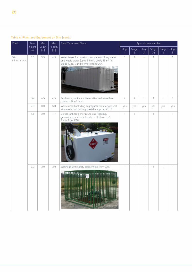
Plant Max height
(m)
Max width (m)
Max length
(m)
Plant/Comment/Photo Approximate Number
Stage 1
Stage 2
Stage 3
Stage 3a
Stage 4
Stage 5
Site infrastructure
3.0 5.5 4.5 Water tanks for construction water/drilling water and waste water (up to 55 m3). Likely 15 m3 for Stage 1, 3a, 4 and 5. Photo from CA7.
1 2 - 1 1 2
n/a n/a n/a Foul water tanks: 4 x tanks attached to welfare cabins – 20 m3 in all
4 4 1 1 1 1
2.0 8.0 5.0 Waste area (including segregated skip for general site waste (not drilling waste) – approx. 40 m2
yes yes yes yes yes yes
1.5 2.0 1.7 Diesel tank for general site use (lighting, generators, site vehicles etc) – likely 4-5 m3. Photo from CA8.
1 1 1 1 1 1
2.0 2.0 2.0 Wellhead with safety cage. Photo from CA9. – – 1 1 1 –
Table 4: Plant and Equipment on Site (cont.)
28

Table 4: Plant and Equipment on Site (cont.)
Plant Max height
(m)
Max width (m)
Max length
(m)
Plant/Comment/Photo Approximate Number
Stage 1
Stage 2
Stage 3
Stage 3a
Stage 4
Stage 5
Construction & Operational Plant
3.0 2.3 5.0 Concrete mixer: Brought onto site with water, sand and cement. Batched on site from within vehicle to prevent concrete hardening in case of delay. Photo shows 12 m3 vehicle. Photo from CA10.
2 - - - - -
6.7 2.8 2.8 Cement silo : Brought onto site on a truck. Photo from CA11.
1 3 - - - 1
2.5 2.5 3.0 Cement pump. Photo from CA12.
1 1 - 1 - 1
35 7.0 12.5 30T crane: For Installation of rigs. Photos from CA13.
- 1 - 1 (1) 1
50 7.0 12.5 80T crane: For installation of main rig and lifting kit into place as necessary(alternative). Photo from CA14.
- (1) - - - -
3.0 5 5 Wireline truck: For listening well operations (as in BOX 8) and logging unit for wireline coring. Photo from CA15.
- 1 - - 1 -
29

Plant Max height
(m)
Max width (m)
Max length
(m)
Plant/Comment/Photo Approximate Number
Stage 1
Stage 2
Stage 3
Stage 3a
Stage 4
Stage 5
Construction & Operational Plant
3.0 5 5 Wireline truck: For listening well operations (as in BOX 8) and logging unit for wireline coring. Photo from CA15.
- 1 - - 1 -
10 5 5 Wireline mast: For listening well operations (as in BOX 8). Referenced in CA16.
- - - - 1 -
3.0 5 5 Elevated work platform: For listening well operations (as in BOX 8). Referenced in CA16.
- - - - 1 -
2.6 1.2 2.5 Rollers: Levelling surface of site. Photo from CA17. 2 - - - - -
3.2 3.9 5.5 Dozers: Stripping soils and forming soil bunds. Photo from CA18.
2 - - - - 2
9.0 3.2 8.5 Excavator: Stripping soils and forming soil bunds. Photo from CA19.
1 - - - - 1
3.3 2.5 4.5 Dumper truck: Stripping soils and forming soil bunds. Photo from CA20.
2 - - - - 2
Table 4: Plant and Equipment on Site (cont.)
30

Table 4: Plant and Equipment on Site (cont.)
Plant Max height
(m)
Max width (m)
Max length
(m)
Plant/Comment/Photo Approximate Number
Stage 1
Stage 2
Stage 3
Stage 3a
Stage 4
Stage 5
Drilling rigs 32 5 10 Workover rig. Photos from CA21 showing rigs approx. 28 m tall and 32 m tall.
- 1 - 1 (1) 1
60 32 12 Main rig: As outlined in BOX 3 – referenced in CA22
- 1 - - - -
Kit associated with drilling rigs
3.5 2.7 7.7 Fuel tank plus bund: 20,000 litre diesel tank (20 m3) (double skinned). Photo from CA23.
- 2 - 1 (1) 1
2.6 3.6 16.8 Mud tank (3 tanks combined – approx. 143 m3 in total). Photos from CA24.
- 1 - 1 - 1
3.3 3.3 9.2 Mud pump. Photo from CA25.
- 2 - 1-2 - 1-2
3.0 2.5 6.0 Mud mixer. Photo from CA26.
- 1 - 1 - 1
2.3 2.7 12 Settling tank - 1 - 1 - 1
2.3 2.6 11.4 Shaker tank/skid (3 shakers on a skid) Photos from CA27.
Mud tank and shaker combined
- 1 - 1 - -
31

Plant Max height
(m)
Max width (m)
Max length
(m)
Plant/Comment/Photo Approximate Number
Stage 1
Stage 2
Stage 3
Stage 3a
Stage 4
Stage 5
Kit associated with drilling rigs
2.5 2.5 5.8 Surge tank - 1 - 1 - -
3.5 2.9 6.5 Cement tank & Well kill tank - 2 - 2 - 2
3.5 2.5 12 Cuttings handling (skip following treatment in shaker tank/settling tank)
- 1 - 1 - 1
2.6 12 12 Mud storage (segregated tanks) - 1 - - - 1
10.0 2.5 2.5 Emergency vent - 1 - 1 - -
3.2 3.5 15.2 Silicon Controlled Rectifier (SCR) (rig power control). Photo from CA28.
- 1 - - - -
4.5 2.5 6.5 Koomey (Pressure control). Photo from CA29.
- 1 - 1 - 1
4.0 3.0 8.9 Blow out preventor and skid and choke manifold. Photo from CA30.
- 1 - 1 (1) 1
2.5 2.5 6.0 Compressor and housing for power for top drive. Photo from CA31.
- 2 - - - -
Drill pipe rack (to be stored in dedicated area adjacent to bunding in corner of site). Photo from CA32.
- yes - - - -
Table 4: Plant and Equipment on Site (cont.)
32

Table 5: Summary of traffic movements by vehicle type (indicative)
Stage 1 Site construction
Stage 2 Drilling, Coring & Suspension
Stage 3 Routine maintenance (annual)
Stage 3a Well intervention/ workover (if required)
Stage 4 Listening well operations
Stage 5 Decommissioning and restoration
Total over 5 years (excluding Stage 3a & 4)
Total over 5 years (including Stage 3a & 4)
Number of days 77 84 365 16 21 42
Total small vehicle movements (<3.5t)
36 24 986 6 8 10 5212 5484
Total Large Goods Vehicles (LGV) movements (3.5t-7.5t) 446 976 12 144 180 294 1752 2628
Total Heavy Goods Vehicles (HGV) movements (7.5t-32t)
1220 166 0 22 28 1158
4602 6332
Total HGV movements (>32t)
454 1254 28 266 280 188
Total abnormal load movements
42 28 0 6 8 8
Total LGV, HGV and abnormal movements (>3.5 t)
2162 2424 40 438 496 1648 6354 8960
Total movements (all vehicles) 2198 2448 1026 444 504 1658 11566 14444
Daily average movements (all vehicles)
29 30 3 28 24 40
33

Stage 1 Site construction
Stage 2 Drilling, Coring & Suspension
Stage 3 Routine maintenance (annual)
Stage 3a Well intervention/ workover (if required)
Stage 4 Listening well operations
Stage 5 Decommissioning and restoration
Staff and stakeholder visits 476 994 730 150 188 244
Regular site requirements (potable water, skip change, raod sweeper, fuel, drainage removal etc)
360 300 54 80 168
Site construction 1192
Site set up (delivery of screening cabins etc) 70 32
Installation of cellar and monitoring boreholes 100
Mobilisation of main rig 224
Drilling of preliminary section 52
Drilling of main core 498
Suspension of well 110
Demobilisation of main rig 270
Weekly maintainance (technical and environmental monitoring) 208
Monthly maintenance (drainage removal and environmental monitoring)
48
Quaterly maintenance (facilities maintenance) 24
Annual maintenance (wellhead inspection) 16
Well intervention 240
Listening well operations 236
Plugging and abandonment (decommissioning) 74
Restoration 1140
TOTAL 2198 2448 1026 444 504 1658
Table 6: Breakdown of total traffic movements into activities at each Stage (indicative)
34

Stage 1 Site construction
Stage 2 Drilling, Coring & Suspension
Stage 3 Routine maintenance (annual)
Stage 3a Well intervention/ workover (if required)
Stage 4 Listening well operations
Stage 5 Decommissioning and restoration
Max small vehicle movements (<3.5t) per day 4 2 20 2 2 4
Max LGV movements (3.5t-7.5t) per day 10 16 6 12 12 56
Max HGV movements (7.5t-32t) per day 58 10 0 4 4 54
Max HGV movements (>32t) per day 50 46 6 46 44 40
Max abnormal loads per day 14 6 0 2 2 3
Max HGV movements (>7.5t) per day 60 60 32 59 55 60
Max movements per day (all vehicles) 70 60 32 59 55 62
Table 7 Maximum daily traffic movements by vehicle type at each Stage (indicative)
Table 7: Maximum daily traffic movements by vehicle type at each Stage (indicative)
35

In addition to planning consent, the Proposal would be regulated by other agencies as follows. These requirements have been taken account of in the design of the Proposal;
+ Well design and construction – Health and Safety Executive (HSE) and Coal Authority (interaction with coal seams)
+ Well integrity during operation – independent qualified experts, HSE and Environment Agency
+ Operation of the surface equipment on the well pad – Environment Agency and HSE
+ Extractive (mining) waste – Environment Agency
+ Flaring or venting of gas (as a mining waste for the proposed vertical core well) – Environment Agency6
+ Well decommissioning and abandonment – HSE and Environment Agency
INEOS would also follow its own internal procedures and safety and environmental management processes as indicated in BOX 1 including the 20 Principles for Process and Behavioural Safety and INEOS Group Guidance Notes.
INEOS Shale achieved certification to ISO 9001, ISO 14001 and OHSAS 18001 (Occupational Health and Safety Assessment Series) by DNV in 2017, requiring certain standards of Quality Management, Environmental Management and Occupational Health and Safety to be followed. INEOS contractors would also be expected to participate in safety teams, contribute to investigations and incident learning, and suggest ongoing improvements in safety standards and procedures.
Onshore oil and gas development in the UK is subject to the same level of HSE regulation that other business sectors are including:
+ Health and Safety at Work etc. Act 1974
+ The Management of Health & Safety at Work Regulations 1999
+ Workplace (Health, Safety and Welfare) Regulations 1992
+ Provision and Use of Work Equipment Regulations 1998
+ Lifting Operations and Lifting Equipment Regulations 1998
+ Manual Handling Operations Regulations 1992
+ Control of Substances Hazardous to Health Regulations 1999
+ Personal Protective Equipment at Work Regulations 1992
+ Reporting of Injuries, Diseases and Dangerous Occurrences Regulations 2013 (RIDDOR)
+ Work at Height Regulations 2005
+ Health and Safety (Consultation with Employees) Regulations 1996
+ Pressure Systems Safety Regulations 2000
There are established industry specific regulations, which place specific duties on Operators in addition to those required under the general HSE regulation noted above,
Regulation and Internal Management4.0such as the Borehole Sites and Operations Regulations 1995 and Offshore Installations and Wells (Design and Construction) Regulations 1996 (DCR 1996). These require the integrity of wells to be maintained over the lifecycle of the well (design, construction, use, plugging and abandonment). These regulations ensure appropriate well controls are in place during all phases of the well’s life.
DCR 1996 imposes a general duty on the well operator to ensure that a well is so designed, modified, commissioned, constructed, equipped, operated, maintained, suspended and abandoned so as to ensure, so far as is reasonably practicable that there can be no unplanned escape of fluids from the well and that the risks to the health and safety of persons from it or anything in it or in the strata to which it is connected are as low as is reasonably practicable. DCR 1996 also stipulates that before the design of a well is commenced or adopted the well operator is obliged to put into effect arrangements for examinations by independent persons to ensure that the well is designed, constructed and maintained properly.
In all, there are over 100 pieces of regulation governing the conduct of onshore operators in the UK. INEOS also adopts industry best practice, such as International Association of Oil & Gas Producers standards, for relevant operations such as seismic acquisition. Other relevant best practice that would be followed includes UKOOG Onshore Shale Gas Well Guidelines and Oil & Gas UK Well Life Cycle Integrity Guidelines.
All site works would be undertaken in accordance with Environment Agency guidance as well as regulations. The proposed activities would require an environmental permit under the Environmental Permitting (England and Wales) Regulations 2016 to manage extractive (mining) waste. The site would be operated in accordance with Standard Rules SR2015 No 1 relating to the “management of extractive waste, not including a waste facility, generated from onshore oil and gas prospecting activities including drilling, coring, leak off testing, acid wash and decommissioning but excluding hydraulic fracturing for the production of oil or gas (using oil and water based drilling mud)”. It is not proposed to carry out acid wash as part of this Proposal. Management according to Standard Rules indicates that the Environment Agency does not consider a properly managed site undertaking the relevant activity to generate significant environmental risk meriting management under a bespoke permit.
Abandonment (decommissioning) of the well would also be carried out according to best practice at the time of decommissioning (such as in the Oil and Gas Suspension and Abandonment Guidelines), and abandonment plans would be agreed with the MPA, OGA and Environment Agency prior to commencing abandonment.
6. SR2015 No1 requires that there will be no point source emissions to air, land or water. Target formations for the vertical core well are expected to be normally pressurised with no over pressure. Well control would be maintained by the weight of the drilling mud used. In the unlikely event formations are found to be over pressurised, anywhere gas is produced this must be managed at the surface. A blow out preventer would be in place to ensure the wellbore is sealed and any oil or gas circulated out is safely managed. The mud weight would then be adjusted to prevent any further release of gas or oil. The Environment Agency would be notified of any release

Figures
STAGE 2 Drilling and Coring
STAGE 4 Use of the Well as Listening Well
STAGE 5 Abandonment (Decommissioning) and Restoraon
STAGE 1 Site Development and Establishment
STAGE 3 Maintenance of the Suspended Well Site Listening Well
Plan shows end of Stage 1, just before the rig is brought to site. Plan shows site at the “peak” of acvity, with the rig and all necessary drilling and coring equipment on site.
Following compleon of the drilling, coring and necessary logging, the well would be suspended using the drilling rig. Plan shows suspended well protected by a steel wellhead protecon cage.
Plan shows site during listening operaons with a listening truck and either a crane or a workover rig on site.
Plan shows site aer compleon of abandonment and restoraon.
KEY:
CABINS FOR STORAGE, OFFICE AND WELFARE SPACE AND STORAGE TANKS FOR SURFACE WATER AND FUEL POSITIONED AROUND PERIMETER OF SITE
CABINS FOR STORAGE, OFFICE AND WELFARE SPACE AND STORAGE TANKS FOR SURFACE WATER AND FUEL POSITIONED AROUND PERIMETER OF SITE
DRILLING RIG AND ANCILLARY KIT INCLUDING TANKS, PUMPS AND CONTROL EQUIPMENT (WITHIN HATCHED AREA)
Figure P1
37

N.B
. Pho
togr
aph
show
s fea
ture
s th
at w
ould
not
be
pres
ent t
hrou
ghou
t ope
raon
s, b
ut il
lust
rate
a s
tand
ard,
sim
ilar s
ite a
t one
sta
ge (d
rillin
g – S
tage
2)
Wel
l pad
Appr
ox. 9
1m x
99m
(0.9
ha) w
ith a
ddi�
onal
w
ater
tank
/car
par
k ar
ea –
1ha
in to
tal.
Pl
anni
ng a
pplic
a�on
bou
ndar
y (in
clud
ing
acce
ss tr
ack)
: 1.8
3ha
Thes
e de
sign
and
mi�
ga�o
n re
quire
men
ts
will
be
subj
ect t
o pl
anni
ng c
ondi�o
ns.
Surf
acin
g an
d lin
ing
of si
te
The
site
will
be
lined
with
a p
rote
c�ve
geo
tex�
le a
nd
impe
rmea
ble
geom
embr
ane
(450
mm
bel
ow
nish
ed si
te
surf
ace)
cov
ered
with
agg
rega
te. T
he li
ner w
ill b
e in
stal
led
by s
peci
alist
subc
ontr
acto
r and
wel
d jo
inte
d to
en
sure
it is
wat
er�g
ht. A
con
cret
e pa
d/ h
ards
tand
ing
(25m
x 1
7m) a
nd w
ellh
ead
cella
r (2.
5m d
iam
eter
) will
be
deve
lope
d in
the
site
cen
tre
for t
he ri
g an
d co
re w
ell.
Thes
e w
ill b
e se
para
te fr
om th
e sit
e pe
rimet
er d
rain
age
syst
em.
The
cella
r will
be
wel
ded
to th
e m
embr
ane
to
mai
ntai
n m
embr
ane
inte
grity
.
Thes
e de
sign
and
mi�
ga�o
n re
quire
men
ts w
ill b
e su
bjec
t to
pla
nnin
g co
ndi�
ons.
The
Env
ironm
ent P
erm
it w
ill a
lso
requ
ire effi
cien
t site
con
tain
men
t as p
art o
f the
Sta
ndar
d Ru
les W
aste
Man
agem
ent P
lan.
Site
dra
inag
e
Surf
aces
gra
ded
to 1
/100
fall
to e
nsur
e th
at
uids
do
not p
ool a
nd
beco
me
a ha
zard
. Site
and
dra
inag
e siz
ed fo
r a 1
in 1
00 y
ear
ood
even
t. Su
rfac
e w
ater
run‐
off fr
om th
e dr
ill
oor w
ill b
e ch
anne
lled
to
the
impe
rmea
ble
wel
l cel
lar,
from
whe
re it
wou
ld b
e ro
u�ne
ly
pum
ped
for r
emov
al fr
om th
e sit
e. S
urfa
ce w
ater
run
off fr
om th
e re
mai
nder
of t
he si
te w
ill
ow to
a p
erim
eter
wat
er st
orag
e pi
pe v
ia
a su
mp.
Thi
s sur
face
wat
er w
ould
be
stor
ed in
a d
oubl
e sk
inne
d ta
nk
(app
rox.
15m
3 in v
olum
e). A
ll w
ater
will
be
rem
oved
from
the
site
for
trea
tmen
t.
Thes
e de
sign
and
mi�
ga�o
n re
quire
men
ts w
ill b
e su
bjec
t to
plan
ning
co
ndi�
ons.
The
Env
ironm
ent P
erm
it w
ill a
lso re
quire
all
surf
ace
wat
er d
rain
s to
be se
cure
, and
all
was
te to
be
prop
erly
man
aged
in
acco
rdan
ce w
ith th
e W
aste
Man
agem
ent P
lan.
Boun
dary
trea
tmen
ts
A 2m
hig
h He
ras s
ecur
ity fe
nce,
pai
nted
in a
rece
ssiv
e co
lour
, will
be
pro
vide
d ar
ound
the
site
perim
eter
, whi
ch w
ill b
e pi
nned
in
the
grou
nd. B
etw
een
the
fenc
ing
and
the
site
com
poun
d, so
il bu
nds u
p to
3.5
m h
igh
and
6m w
ide
with
45
degr
ee b
a�er
s will
be
con
stru
cted
. The
bun
ds w
ill b
e co
vere
d w
ith a
gra
ss se
eded
ge
otex�l
e bl
anke
t. 1.
3m h
igh
site
oper
a�on
al fe
ncin
g w
ill b
e pl
aced
on
top
of th
e bu
nd (4
.8m
hig
h in
tota
l).
Thes
e de
sign
and
mi�
ga�o
n re
quire
men
ts w
ill b
e su
bjec
t to
plan
ning
con
di�o
ns.
Ease
men
ts fo
r uli
es
A 3m
stan
doff
from
pip
elin
es
and
unde
rgro
und
cabl
ing
will
be
fenc
ed off,
and
any
wor
ks
with
in th
is un
dert
aken
by
hand
, fo
llow
ing
liaiso
n w
ith th
e u�
lity
stat
utor
y un
dert
aker
(s).
Ea
sem
ents
of 3
m fo
r ove
rhea
d po
wer
lines
and
1m
from
road
s (p
lus t
he ro
ad w
idth
) will
also
be
mai
ntai
ned
for a
ll w
orks
. A
full
u�lit
y se
arch
will
be
carr
ied
out a
t eac
h sit
e.
The
requ
ired
ease
men
ts w
ill b
e su
bjec
t to
plan
ning
con
di�o
ns
and
also
the
requ
irem
ent o
f th
e st
atut
ory
unde
rtak
ers.
Emis
sion
sou
rce
Desc
rip�o
n
Mi�
ga�o
n
Ligh
ng a
nd se
curit
y
Low
leve
l sec
urity
ligh
�ng
will
be
pres
ent o
n th
e sit
e th
roug
hout
th
e lif
e�m
e of
the
perm
issio
n. T
his w
ill in
clud
e a
mob
ile u
nit w
ith
sens
or a
t the
mai
n ga
te (o
nly
exte
rnal
ly fa
cing
ligh
t), a
nd m
obile
, se
nsor
con
trol
led
units
to li
ght t
he c
ompo
und o
or a
s nee
ded
(up
to 9
m ta
ll). L
ight
s will
be
desig
ned
to h
ave
min
imal
upw
ard
light
ou
tput
ra�n
g. C
CTV
will
be
inst
alle
d at
the
site.
The
ligh�
ng d
esig
n w
ill fo
llow
the
Gui
danc
e N
otes
for t
he
Redu
c�on
of O
btru
sive
Ligh
t (G
N01
:201
1) fr
om th
e In
s�tu
te o
f Li
gh�n
g Pr
ofes
siona
ls. T
his w
ould
be
angl
ed a
way
from
sens
i�ve
re
cept
ors a
nd sh
ield
ed w
here
app
ropr
iate
. The
ligh
�ng
desig
n w
ill
be su
bjec
t to
plan
ning
con
di�o
ns.
Publ
ic R
oad
Pass
ing
plac
es p
rovi
ded
on th
e pu
blic
road
whe
re n
eces
sary
to
ensu
re sa
fe a
cces
s to
the
site.
Junc�o
ns w
ould
hav
e ap
prop
riate
vi
sibili
ty sp
lay
for t
he la
rges
t site
veh
icle
s.
Mea
sure
s suc
h as
whe
el w
ashi
ng w
ould
ens
ure
mud
and
deb
ris
from
the
site
is no
t tra
cked
ont
o th
e pu
blic
road
by
site
vehi
cles
, an
d in
dus
ty c
ondi�o
ns d
ampi
ng d
own
of th
e sit
e w
ould
pre
vent
du
st. T
hese
mi�
ga�o
n re
quire
men
ts w
ill b
e su
bjec
t to
plan
ning
co
ndi�
ons.
Acce
ss T
rack
s
All n
ew a
cces
s tra
cks w
ould
be
a m
inim
um 3
m w
ide
and
450m
m d
eep.
All
trac
ks li
ned
with
a p
rote
c�ve
ge
otex�l
e an
d im
perm
eabl
e m
embr
ane
and
surf
aced
w
ith su
bbas
e an
d ag
greg
ate
in la
yers
to re
quire
d de
pth.
Dra
inag
e w
ould
be
to th
e tr
ack
edge
. Acc
ess
trac
k w
ould
be
fenc
ed w
ith H
eras
fenc
ing
from
the
rst
secu
rity
gate
.
The
acce
ss tr
ack
loca�o
n an
d de
sign
will
be
subj
ect t
o pl
anni
ng c
ondi�o
ns.
Was
te m
anag
emen
t
All w
aste
mat
eria
ls an
d u
ids
will
be
stor
ed in
ded
icat
ed
area
s. A
ny sk
ips w
ould
be
cove
red
to p
reve
nt w
ind
blow
of
li�
er o
r dus
t.
The
acce
ss tr
ack
loca�o
n an
d de
sign
will
be
subj
ect t
o pl
anni
ng c
ondi�o
ns. T
he W
aste
M
anag
emen
t Pla
n in
the
Stan
dard
Rul
es E
nviro
nmen
tal
Perm
it an
d pl
anni
ng c
ondi�o
ns
rela�n
g to
was
te m
anag
emen
t (e
spec
ially
dus
t man
agem
ent
and
amen
ity p
rote
c�on
) will
be
follo
wed
.
FIG
URE
P2
GEN
ERIC
FEA
TURE
S O
F TH
E PR
OPO
SED
VERT
ICAL
CO
RE W
ELL
SITE
TH
AT W
OU
LD B
E CO
NST
ANT
THRO
UG
HOU
T O
PERA
TIO
NS
DATE
: 05/
05/2
017
IN
EOS
Shal
e 38
Han
s Cre
scen
t, Kn
ight
sbrid
ge,
Lond
on, S
W1X
0LZ
w
ww
.ineo
ssha
le.c
om
Chem
ical
sto
rage
Drill
ing
mud
s and
fuel
for t
he
rig a
nd g
ener
ator
s will
be
stor
ed e
ither
in d
oubl
e sk
inne
d st
eel t
anks
or i
n an
im
perm
eabl
e bu
nded
are
a.
Drip
tray
s will
be
prov
ided
un
der r
efue
ling
poin
ts a
nd
stan
ding
mac
hine
ry.
The
chem
ical
and
fuel
stor
age
will
be
subj
ect t
o pl
anni
ng
cond
i�on
s and
als
o th
e co
ndi�
ons o
f the
Env
ironm
ent
Perm
it fr
om th
e En
viro
nmen
t Ag
ency
.
Park
ing
Ther
e w
ill b
e sp
ace
for 1
0 ca
rs o
n sit
e, a
nd
for H
GVs
to tu
rn in
the
site
with
out n
eedi
ng
to m
anoe
uvre
on
the
publ
ic h
ighw
ay.
Thes
e de
sign
and
mi�
ga�o
n re
quire
men
ts
will
be
subj
ect t
o pl
anni
ng c
ondi�o
ns.
Figure P2
38

FIG
URE
P3
FEAT
URE
S O
F TH
E VE
RTIC
AL C
ORE
WEL
L SI
TE D
URI
NG
STAG
E 1
DATE
: 25/
04/2
017
INEO
S Sh
ale
38 H
ans C
resc
ent,
Knig
htsb
ridge
, Lon
don,
SW1X
0LZ
ww
w.in
eoss
hale
.com
Emis
sion
sou
rce
Desc
rip�o
n
Mi�
ga�o
n
VEG
ETA
TIO
N R
EMO
VA
L A
ND S
TRIP
PIN
G T
OPS
OIL
:
All
soil
will b
e ke
pt s
epar
ate
from
oth
er c
onst
ruct
ion
acti
viti
es f
or r
esto
rati
on. T
op 3
00m
m o
f to
psoi
l and
su
bsoi
l, w
here
nec
essa
ry, w
ill b
e re
mov
ed f
or b
undi
ng.
The
layo
ut a
nd a
rran
gem
ents f
or t
opso
il re
mov
al a
nd
stor
age
will b
e su
bjec
t to
pla
nnin
g co
ndit
ions
.
AD
DIT
ION
AL
LIG
HTI
NG
:
Dur
ing
Stag
es 1 s
ite
light
ing
will b
e su
pple
men
ted
wit
h ad
diti
onal m
obile
, con
stru
ctio
n lig
htin
g (u
p to
9m
mas
ts). C
urre
nt li
ghti
ng d
esig
n is f
or u
p to
9m h
igh
sile
nced
min
i lig
htin
g to
wer
. The
ligh
ting
des
ign
is
show
n in t
he p
lann
ing
appl
icat
ion
draw
ings
.
The
layo
ut a
nd a
rran
gem
ent
of t
he s
ite
infr
astr
uctu
re
will b
e su
bjec
t to
pla
nnin
g c
ondi
tion
s.
MO
NIT
OR
ING B
OR
EHO
LES:
Inst
alle
d un
der
perm
itte
d de
velo
pmen
t ri
ghts (
and
not
form
ing
part o
f th
is a
pplic
atio
n) t
o al
low o
ngoi
ng m
onit
orin
g of g
roun
dwat
er.
Mon
itor
ing
will b
e ag
reed
wit
h th
e En
viro
nmen
t A
genc
y, a
nd w
ill b
e su
bjec
t to
the
con
diti
ons
of t
he E
nvir
onm
enta
l Per
mit
.
CUT
& F
ILL:
Cut
and
fill
will b
e re
quir
ed o
n th
e si
te t
o cr
eate a le
vel
surf
ace. T
he s
ite
desi
gn h
as a
llow
ed f
or t
his, a
nd t
imin
gs a
nd
equi
pmen
t pr
ovid
ed in
thi
s pl
anni
ng a
pplic
atio
n ta
ke a
ccou
nt
of t
he r
equi
red
chan
ges
in le
vels
. A b
alan
ce o
f cu
t an
d fi
ll ha
s be
en e
stab
lishe
d, a
nd a
ll cu
t m
ater
ial w
ill b
e re
tain
ed o
n si
te.
A b
alan
ce o
f cu
t an
d fi
ll w
ill b
e es
tabl
ishe
d to
kee
p ‘c
ut’
mat
eria
l on
site
.
WEL
L CE
LLA
R I
NST
ALL
ATI
ON
:
The
wel
l cel
lar
will b
e in
stal
led
by e
xcav
atio
n, a
nd a 2
.5m d
iam
eter
con
cret
e ri
ng
inst
alle
d an
d he
at s
eale
d to
the
lini
ng t
o pr
ovid
e an
impe
rmea
ble
seal
. Thi
s m
etho
d of in
stal
lati
on e
nsur
es t
hat
ther
e is a
n im
perm
eabl
e ce
llar
from
whi
ch t
he
wel
l can
be
drill
ed, h
avin
g se
aled
off t
he s
urfa
ce la
yers
.
The
conc
rete w
ell c
ella
r w
ill b
e lin
ed w
ith
2.5m
dia
met
er m
anho
le r
ings
sup
port
ed
on m
ass
conc
rete p
oure
d ag
ains
t th
e dr
ill p
ipe
casi
ng. T
he d
rill
pipe
cas
ing
will b
e se
aled
wit
h an
HD
PE li
ner. T
he d
esig
n w
ill b
e su
bjec
t to
pla
nnin
g co
ndit
ions
and
th
e co
ndit
ions
of
the
Envi
ronm
enta
l Per
mit
.
ACC
OM
MO
DA
TIO
N A
ND W
ELFA
RE
FACI
LITI
ES:
Off
ices
and
wel
fare
fac
iliti
es w
ill b
e pr
ovid
ed t
o ac
com
mod
ate
pers
onne
l and
sp
ace
for
wor
ksho
ps a
nd s
tora
ge. S
ite
faci
litie
s, t
oile
ts a
nd s
how
er b
lock
s ar
e se
lf
cont
aine
d an
d no
t co
nnec
ted
to s
ewer
. So
lid a
nd li
quid w
aste a
re r
emov
ed f
rom
site b
y lic
ense
d co
ntra
ctor
as
need
ed.
The
layo
ut a
nd a
rran
gem
ent
of t
he s
ite
infr
astr
uctu
re w
ill b
e su
bjec
t to
pla
nnin
g
cond
itio
ns. W
aste m
anag
emen
t ac
tivi
ties
w
ill b
e su
bjec
t to
the
con
diti
ons
of t
he
Envi
ronm
enta
l Per
mit f
rom t
he
Envi
ronm
ent
Age
ncy.
SITE
AR
EA:
Tota
l sit
e ar
ea a
ppro
xim
atel
y 1.
83ha
des
igne
d w
ith
1 in
100
falls
to
chan
nel w
ater
to
peri
met
er s
urfa
ce w
ater
st
orag
e pi
pe a
nd t
ank. R
amps
dev
elop
ed f
or s
afe
acce
ss a
nd e
gres
s fr
om h
ards
tand
ing
area
s. P
edes
tria
n se
greg
atio
n fe
ncin
g pl
aced
on
all s
ides
of
hard
stan
ding
ar
ea.
Conc
rete p
ad d
evel
oped
in c
entr
e of s
ite
for
rig.
Conc
rete k
erb
ston
es (
cabl
e tr
ay s
uppo
rt)
at r
equi
red
spac
ing
and
posi
tion
s w
ithi
n th
e ha
rdst
andi
ng a
rea, a
s sh
own
on t
he p
lann
ing
appl
icat
ion
draw
ings
.
Dri
lling
pla
tfor
m w
ill c
ompr
ise
300m
m d
eep
rein
forc
ed
conc
rete s
trip
s ly
ing
on a
n im
perm
eabl
e H
DPE
line
r an
d ge
otex
tile m
embr
ane. T
he la
yout
and
arr
ange
men
t of
the
site in
fras
truc
ture
will b
e su
bjec
t to
pla
nnin
g
cond
itio
ns.
SOIL B
UN
DIN
G:
Up
to 3
.5m h
igh
x 6m
wid
e so
il bu
nds
form
ed f
rom 3
00m
m o
f to
psoi
l an
d an
y su
bsoi
l req
uire
d w
ill b
e sc
rape
d fr
om t
he s
ite. T
opso
il an
d su
bsoi
l will b
e st
ored
sep
arat
ely
if r
equi
red.
Soil
com
pact
ed in
laye
rs t
o th
e re
quir
ed d
epth
on
the
bund
, pos
sibl
y w
ith
prot
ecti
ve g
eote
xtile
and
impe
rmea
ble
HD
PE m
embr
ane
laye
r as
re
info
rcem
ent
at r
equi
red
dept
h. S
oil b
unds
will b
e gr
asse
d w
ith
a se
eded
geo
text
ile b
lank
et t
o im
prov
e st
abili
ty a
nd p
rovi
de v
isua
l as
wel
l as
acou
stic s
cree
ning
.
Figure P3
39
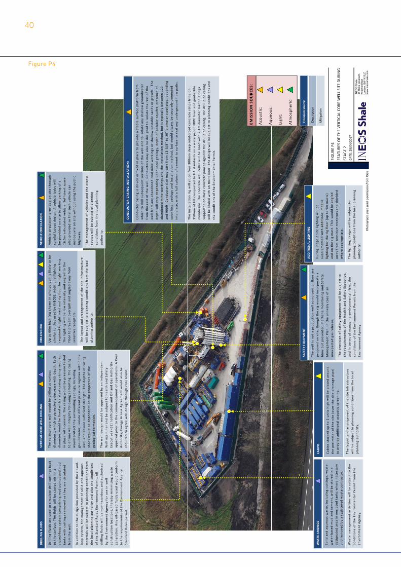
FIG
URE
P4
FEAT
URE
S O
F TH
E VE
RTIC
AL C
ORE
WEL
L SI
TE D
URI
NG
STAG
E 2
DATE
: 28/
04/2
017
IN
EO
S S
hale
38
Han
s C
resc
ent,
Kni
ghts
brid
ge
Lond
on, S
W1X
0LZ
w
ww
.ineo
ssha
le.c
om
EMIS
SIO
N S
OU
RCE
S:
Aco
usti
c:
Aqu
eous
:
Ligh
t:
Atm
osph
eric
:
DRI
LLIN
G F
LUID
S
Dri
lling
flu
ids
are
used
to
circ
ulat
e dr
ill c
utti
ngs
back
to
the
sur
face
. The
flu
ids
will b
e st
ored
wit
hin
a cl
osed
‐loo
p sy
stem
com
pris
ing
mud
pum
ps a
nd m
ud
tank
s w
ith
cutt
ings
rem
oved
as
they
are
cir
cula
ted
from
the
wel
l.
In a
ddit
ion
to t
he m
itig
atio
n pr
ovid
ed b
y th
e cl
osed
‐lo
op s
yste
m, t
he m
anag
emen
t of s
olid a
nd a
queo
us
mat
eria
ls w
ill b
e su
bjec
t to
pla
nnin
g co
ndit
ions
fro
m
the
loca
l pla
nnin
g au
thor
ity
and
also
the
con
diti
ons
of t
he S
tand
ard
Rule
s En
viro
nmen
t Pe
rmit
. All
drill
ing
flui
ds w
ill b
e no
n‐ha
zard
ous
and
auth
oris
ed
by t
he E
nvir
onm
ent
Age
ncy
for
use
in w
ell
cons
truc
tion
loca
tion
s, t
here
by m
inim
isin
g w
aste
gene
rati
on. A
ny o
il‐ba
sed
flui
ds u
sed
wou
ld c
onfo
rm
to t
he r
equi
rem
ents o
f th
e En
viro
nmen
t A
genc
y St
anda
rd R
ules
per
mit
.
DRI
LLIN
G R
IG
Up
to 6
0m h
igh
(rig s
how
n in p
hoto
grap
h is li
kely t
o be
si
mila
r to
tha
t us
ed b
y IN
EOS)
. Add
itio
nal l
ight
ing
requ
ired
to
light
mas
t an
d ri
g fl
oor
for
nigh
t w
orki
ng.
The
light
ing
will b
e lo
w in
tens
ity
and
angl
ed t
o th
e fl
oor
to p
reve
nt o
vers
pill
and
angl
ed a
way
fro
m
sens
itiv
e re
cept
ors.
The
layo
ut a
nd a
rran
gem
ent
of t
he s
ite
infr
astr
uctu
re
will b
e su
bjec
t to
pla
nnin
g co
ndit
ions
fro
m t
he lo
cal
plan
ning
aut
hori
ty.
CABI
NS
Cabi
ns s
tack
ed u
p to
2 u
nits h
igh
will b
e pl
aced
aro
und
the
peri
met
er o
f th
e si
te (
over
the
sit
e dr
aina
ge p
ipe)
to p
rovi
de a
ddit
iona
l aco
usti
c sc
reen
ing.
The
layo
ut a
nd a
rran
gem
ent
of t
he s
ite
infr
astr
uctu
re
will b
e su
bjec
t to
pla
nnin
g co
ndit
ions
fro
m t
he lo
cal
plan
ning
aut
hori
ty.
ADD
ITIO
NAL
LIG
HTI
NG
Dur
ing
Stag
e 2
site li
ghti
ng w
ill b
e su
pple
men
ted
wit
h ad
diti
onal m
obile
lig
htin
g fo
r th
e ri
g fl
oor
(up
to 9
m m
asts
) an
d on
the
rig m
ast. T
his
wou
ld b
e an
gled
aw
ay f
rom s
ensi
tive
rec
epto
rs a
nd s
hiel
ded
whe
re a
ppro
pria
te.
The
light
ing
desi
gn w
ill b
e su
bjec
t to
pl
anni
ng c
ondi
tion
s fr
om t
he lo
cal p
lann
ing
auth
orit
y.
WAS
TE A
RISI
NG
S
Solid
and
aqu
eous
was
te, i
nclu
ding
cut
ting
s, w
aste
wat
er‐b
ased
mud
and
cem
ent, w
ill b
e st
ored
in a
desi
gnat
ed a
rea
in e
nclo
sed
tank
s w
here
nec
essa
ry
and
rem
oved
by
a re
gist
ered
was
te c
ontr
acto
r.
Was
te m
anag
emen
t ac
tivi
ties
will b
e su
bjec
t to
the
co
ndit
ions
of
the
Envi
ronm
enta
l Per
mit f
rom t
he
Envi
ronm
ent
Age
ncy.
SAFE
TY E
QU
IPM
ENT
The
wel
l is
not
a pr
oduc
tion
wel
l so
no v
ent
or f
lare
are
pr
opos
ed o
n si
te, t
houg
h th
e ri
g w
ould in
corp
orat
e a
blow
out
pre
vent
er, m
etha
ne m
onit
orin
g an
d Sa
fety
Man
agem
ent
Plan
, in
the
unlik
ely
case
of
an
unex
pect
ed g
as r
elea
se.
The
prov
isio
n of s
afet
y eq
uipm
ent
will b
e su
bjec
t to
th
e re
quir
emen
ts o
f th
e H
ealt
h an
d Sa
fety E
xecu
tive
, an
d in t
erm
s of m
anag
ing
envi
ronm
enta
l ris
ks, t
he
cond
itio
ns o
f th
e En
viro
nmen
t Pe
rmit f
rom t
he
Envi
ronm
ent
Age
ncy.
VEH
ICLE C
IRCU
LATI
ON
Veh
icle c
ircu
lati
on p
rovi
ded
on s
ite
thro
ugh
care
ful l
ayou
t de
sign
. A v
ehic
le la
yby
will
be p
rovi
ded
on s
ite
to a
llow p
arki
ng o
f a
16.5
m a
rtic
ulat
ed v
ehic
le. S
uffi
cien
t sp
ace
also
pro
vide
d so
tha
t su
ch v
ehic
le c
an
man
oeuv
re o
n si
te w
itho
ut u
sing
the
pub
lic
high
way
.
The
man
agem
ent
of v
ehic
les
and
the
acce
ss
rout
es w
ill b
e su
bjec
t of p
lann
ing
cond
itio
ns f
rom t
he lo
cal p
lann
ing
auth
orit
y.
Emis
sion
sou
rce
Desc
rip�o
n
Mi�
ga�o
n
VERT
ICAL
CO
RE W
ELL
DRI
LLIN
G
The
vert
ical c
ore
wel
l wou
ld b
e dr
illed
at
vari
ous
diam
eter
s, w
hich
pro
gres
sive
ly d
ecre
ase
wit
h de
pth. E
ach
diam
eter
wou
ld b
e lin
ed w
ith
a st
eel c
asin
g st
ring
sec
ured
in p
lace
wit
h ce
men
t. T
he c
asin
g w
ould b
e pr
essu
re t
este
d to
ens
ure
wel
l int
egri
ty f
ollo
win
g ce
men
ting
. The
cas
ing
wou
ld p
rote
ct t
he s
urro
undi
ng g
eolo
gy, i
nclu
ding
gr
ound
wat
er, i
sola
te d
iffe
rent
pre
ssur
e re
gim
es w
ithi
n th
e w
ell,
and
ensu
re s
uffi
cien
t st
reng
th. T
he d
epth
s of c
asin
g sh
oes
wou
ld b
e de
pend
ent
on t
he p
rope
rtie
s of t
he
geol
ogic
al f
orm
atio
n.
The
wel
l des
ign
wou
ld b
e ap
prov
ed b
y an
inde
pend
ent
Wel
l exa
min
er a
nd b
e su
bjec
t to
Hea
lth
and
Safe
ty
Exec
utiv
e (H
SE)
noti
fica
tion
and
Oil
and
Gas
Aut
hori
ty
appr
oval p
rior
to
the
com
men
cem
ent
of o
pera
tion
s. A C
oal
Aut
hori
ty, E
nerg
y A
cces
s A
gree
men
t w
ould a
lso
be
requ
ired
to
agre
e w
ell d
esig
n th
roug
h co
al s
eam
s.
CON
DU
CTO
R C
ASI
NG I
NST
ALL
ATI
ON
:
Cond
ucto
r ca
sing
is d
rive
n or
fix
ed in
pla
ce t
o pr
ovid
e a
stab
le s
urfa
ce p
latf
orm f
rom
whi
ch t
o dr
ill s
ubse
quen
t se
ctio
ns o
f th
e w
ell a
nd t
o is
olat
e an
y sh
allo
w g
roun
dwat
er
from
the
res
t of t
he w
ell.
Cond
ucto
rs m
ay a
lso
be d
esig
ned
to is
olat
e th
e re
st o
f th
e w
ell f
rom a
ny a
band
oned
coa
l min
e w
orki
ngs
or s
hallo
w u
nsta
ble
sand
s or
gra
vels
. Th
e de
pth
will v
ary
depe
ndin
g up
on lo
cal g
eolo
gy, d
epth
of
pota
ble
aqui
fer, p
rese
nce
of
aban
done
d m
ine
wor
king
s an
d th
e in
stal
lati
on m
etho
d, b
ut is
typ
ical
ly b
etw
een
120
and
900f
t. C
ondu
ctor
siz
e m
ay v
ary
from
13‐
3/8"
to
26"
diam
eter
ste
el p
ipe, d
epen
ding
up
on lo
cal g
eolo
gy a
nd in
stal
lati
on m
etho
d, b
ut w
ould a
lway
s be
sec
urel
y ce
men
ted
into
pla
ce, w
ith
a fu
ll co
lum
n of c
emen
t to
sur
face
to
seal a
ny u
nder
grou
nd f
low p
aths
.
The
inst
alla
tion
rig w
ill s
it o
n fo
ur 3
00m
m d
eep
rein
forc
ed c
oncr
ete
stri
ps ly
ing
on
150m
m o
f fi
ll co
mpa
cted
to
HA s
tand
ards
on
a w
ater
proo
f H
DPE
line
r an
d ge
otex
tile
mem
bran
e. T
he c
oncr
ete
wel
l cel
lar
will b
e lin
ed w
ith
2.4m
dia
met
er m
anho
le r
ings
su
ppor
ted
on m
ass
conc
rete p
oure
d ag
ains
t th
e dr
ill p
ipe
casi
ng. T
he d
rill
pipe
cas
ing
will b
e se
aled
wit
h an
HD
PE li
ner. T
he d
esig
n w
ill b
e su
bjec
t to
pla
nnin
g co
ndit
ions
and
th
e co
ndit
ions
of
the
Envi
ronm
enta
l Per
mit
.
Photog
raph
used with
permiss
ion from
IGas
Figure P4
40

41