Embed Size (px)
Citation preview

52 GSE2005
4 General information on mounting positionsMounting Positions
4 Mounting Positions4.1 General information on mounting positions
Mounting position designation
In the case of gear units, SEW-EURODRIVE distinguishes between mounting positionsM1 to M6. The following figure shows the position of the gear unit in mounting positionsM1 to M6.
05395AXXFigure 8: Depiction of mounting positions M1 to M6
M1
M1
M1
M1
M1
M1
M4
M4
M4
M4
M4
M4
M3
M3
M3
M3
M3
M3
M6
M6
M6
M6
M6
M6
M5
M5
M5
M5
M5
M5
M2
M2
M2
M2
M2
M2
R..
F..
K..S..
M1 … M6M1 … M6

GSE2005 53
4
1
2
3
4
5
6
7
8
9
10
11
12
13
14
15
16
17
18
19
20
21
22
Important order informationMounting Positions
4.2 Important order information
The following order information is required for R, F, K and S gearmotors in addition tothe mounting position to exactly determine the design of the drive.
• Position of the power plug connector
• Position of the cable entry of the power plug connector
• Position and orientation of the encoder plug connector
• Terminal box position
Plug connector
Position of power plug connector and cable entry in CFM motors
Possible positions of the power plug connector are 0°, 90°, 180° or 270° as viewed ontothe non-drive end of the motor (onto the fan end).
54686AXXFigure 9: Position "3" of the power plug connector
X
X X X180˚90˚0˚270˚
M1 … M6M1 … M6

54 GSE2005
4 Important order informationMounting Positions
Position of cable entry for DFS motors
Positions "2" and "X" are possible for DFS56M and DFS56L motors ("X" = standard).
Positions "1", "2", "3" and "X" are possible for DFS56H and DFS brake motors.
Standard type Unless indicated otherwise, you will receive the power plug connector type 270° positionwith cable entry "2".
Cable entry for DFS motors with plug connector
A means:
• Cable entry position "2" is possible.
• Cable entry positions "1", "3" possible with brake motor.
B means:
• Cable entry positions "1", "2", "3" are possible.
• Cable entry position "X" only possible at 270°.
C means:
• Cable entry positions "1", "2", "3" are possible.
• Cable entry position "X" is not possible.
54678AXXFigure 10: Cable entry position for DFS56M/L
54679AXXFigure 11: Cable entry position for DFS56H
X 2
X 1 2 3
RFKS
R27F27
R37F37K37S37
R47-R67F57-F67
K47-K67F47
S47 S57 S67
DFS56M A A - - - A A -
DFS56L A A - - - A A -
DFS56H B B C C C B B C
There may be collisions depending on what the customer has installed on the outputend.
M1 … M6M1 … M6

GSE2005 55
4
1
2
3
4
5
6
7
8
9
10
11
12
13
14
15
16
17
18
19
20
21
22
Important order informationMounting Positions
Cable entry position with CFM motors
Positions "X", "1", "2" or "3" are possible with CFM motors ("X" = standard).
Standard type Unless indicated otherwise, you will receive the power plug connector type 270° positionwith cable entry "3" and radial encoder plug (CFM..S.5).
54684AXXFigure 12: Cable entry position with CFM..S.5, radial signal plug
54685AXXFigure 13: Cable entry position with CFM..S.6, angled signal plug
X 1 2 3
X 1 2 3
Important: It is not possible to mount a forced cooling fan to motors with axial encoderplug SM6./SB6.
M1 … M6M1 … M6

56 GSE2005
4 Important order informationMounting Positions
Cable entry for CFM motors with plug connector R27 R37 R47 R57 R67 R77 R87 R97 R107
CFM71S D D G G G G - - -
CFM71M D D G G G G - - -
CFM71L D D D F G G - - -
CFM90S D D D D E F G G -
CFM90M - - D D D F G G -
CFM90L - - D D D D F G -
CFM112S - - D D D D F G G
CFM112M - - - - D D F G G
CFM112L - - - - - D D D G
F27 F37 F47 F57 F67 F77 F87 F97 F107
CFM71S E E F F F G - - -
CFM71M E E E F F G - - -
CFM71L E E E F F G - - -
CFM90S E E F E E F G G -
CFM90M - - - E E E G G -
CFM90L - - - E E E G G -
CFM112S - - - E E E F G G
CFM112M - - - - E E F G G
CFM112L - - - - - E E F G
K27 K37 K47 K57 K67 K77 K87 K97 K107
CFM71S - E E E F G - - -
CFM71M - E E E F G - - -
CFM71L - D E E E G - - -
CFM90S - D E E E F G G -
CFM90M - - D E E E G G -
CFM90L - - - D D D E G -
CFM112S - - - D D B E G G
CFM112M - - - - D D E G G
CFM112L - - - - - D D E G
S37 S47 S57 S67
CFM71S D E G G
CFM71M D E G G
CFM71L D D G
CFM90S - D D E
CFM90M - - - E
CFM90L - - - D
CFM112S - - - D
M1 … M6M1 … M6

GSE2005 57
4
1
2
3
4
5
6
7
8
9
10
11
12
13
14
15
16
17
18
19
20
21
22
Important order informationMounting Positions
D means:
• Cable entry positions "1", "2", "3", "X" are possible.
E means:
• Cable entry positions "2", "3", "X" are possible.
• Cable entry position "1" only possible at 0°, 180°, 270°.
F means:
• Cable entry positions "2", "3", "X" are possible.
• Cable entry position "1" only possible at 270°.
G means:
• Cable entry positions "2", "3", "X" are possible.
• Cable entry position "1" is not possible.
"-" means:
• Gear unit/motor combination not possible.
There may be collisions depending on what the customer has installed on the outputend.
M1 … M6M1 … M6

58 GSE2005
4 Important order informationMounting Positions
Position of motor terminal box and cable entry
The position of the motor terminal box has so far been specified indicated with 0°, 90°,180° or 270° as viewed onto the fan guard = B-end (→ Figure 14). A change in theproduct standard EN 60034 specifies that the following designations for terminal boxpositions will have to be used in future:
• As viewed onto the output shaft = A-end
• Designation as R (right), B (bottom), L (left) and T (top)
This new designation applies to foot-mounted motors without a gear unit in mountingposition B3 (= M1). The previous designation is retained for gearmotors. Figure 14shows both designations. Where the mounting position of the motor changes, R, B, Land T are rotated accordingly. In motor mounting position B8 (= M3), T is at the bottom.
The position of the cable entry can be selected as well.
The following positions are possible:
• With DFS/CFM motors, positions "X", "2", "3"
• With CT/CV motors, positions "X" , "1", "2", "3".
Unless indicated otherwise, you will receive the terminal box type 0° (R) with cable entry"X". We recommend selecting cable entry "2" with mounting position M3.
Cable entry in motor terminal box KK5 and KK6
The following cable entries are possible in CFM motors in conjunction with terminal boxKK5 / KK6:
• Positions "X", "2", "3".
51302AXXFigure 14: Position of terminal box and cable entry
270°
90°
180°
0° (R)
0°(R)
180° (L)
1
XX
X
X
3
2
13
X
2
(T)
(L)
(B)
• When the terminal box is in the 90° (B) position, check to see if the gearmotor hasto be supported.
• The following cable entries are possible in the DT71..BMG motor with gear unitflange diameters 160 mm and 200 mm:
Terminal box position 0° (R) 90° (B) 180° (L) 270° (T)
Possible cable entries "X", "3" "X", "1", "3" "1", "2" "X", "1", "3"
Figure 15: Possible cable entry positions CFM..KK5 and CM..KK6
KK5. KK6. KK6. KK6.
X, 2, 3 X 2 3
M1 … M6M1 … M6

GSE2005 59
4
1
2
3
4
5
6
7
8
9
10
11
12
13
14
15
16
17
18
19
20
21
22
Important order informationMounting Positions
Direction of rota-tion of the drive with a backstop
If the drive has a backstop RS, it will be necessary to indicate the direction of rotationfor the drive. The following definition applies:
In right-angle gear units, it is also necessary to indicate if the direction of rotation is givenlooking onto the A or B end.
Position of output shaft and output flange
In right-angle gear units, it is also necessary to indicate the position of the output shaftand the output flange:
• A or B or AB (→ Figure 17)
Looking onto the output shaft: Clockwise (CW) = Rotating clockwiseCounterclockwise (CCW)= Rotating counterclockwise
02584BXXFigure 16: Direction of rotation of output
AA
B
CCWCCW CCWCCWCWCW CWCW
02585BXXFigure 17: Position of the output shaft and the output flange
A
B
M1 … M6M1 … M6

60 GSE2005
4 Important order informationMounting Positions
Position of the output end in right-angle gear units
In shaft mounted right-angle gear units with a shrink disc, it is also necessary to indicatewhether the A or B end is the output end. In Figure 18 , the A end is the output end. Theshrink disc is located opposite the output end.
In shaft mounted right-angle gear units, the "output end" is equivalent to the "shaftposition" of right-angle gear units with solid shaft.
Sample orders
Change in mounting position
Make sure to read the following information when you operate the gearmotor in amounting position other than the one indicated in the order:
• Adjust lubricant fill quantity to match the new mounting position
• Adjust position of breather valve
• For helical-bevel gearmotors: Contact the SEW-EURODRIVE customer service priorto changing to mounting position M5 or M6 and when changing from M5 to M6 or viceversa.
• For helical-worm gearmotors: Contact the SEW-EURODRIVE customer servicewhen changing to mounting position M2.
03204AXXFigure 18: Position of the output end
AB
You will find the permitted mounting surfaces (= hatched area) in the mounting positionsheets (page 62 and the following pages).
Example: Only the mounting surface at the bottom is possible with helical-bevel gearunits K167/K187 in mounting positions M5 and M6.
Type(examples)
Mounting position
Shaft position
Flange position
Terminal box
position
Cable entry position
Direction of rotation of
output
SF77CV100L4 M6 AB AB 90° "3" -
KA97CV132M4 M4 B - 270° "2" -
KH107CV160L4 M1 A - 180° "3" -
M1 … M6M1 … M6

GSE2005 61
4
1
2
3
4
5
6
7
8
9
10
11
12
13
14
15
16
17
18
19
20
21
22
Key to the mounting position sheetsMounting Positions
4.3 Key to the mounting position sheets
Symbols used The following table shows the symbols used in the mounting position sheets and theirmeaning:
Symbol Description
Breather valve
Oil level plug
Oil drain plug
* With these mounting positions, observe the churning losses given in the "Churning losses" table in section 3.4, page 31.
Position of the terminal box is "Standard"X
Note the following information regarding display of shafts in the mounting positionsheets:
• For gear units with solid shaft: The displayed shaft is always on the A end.
• For shaft mounted gear units: The shaft with dashed lines represents the customershaft. The output end ( = shaft position) is always shown on the A end.
M1 … M6M1 … M6

62 GSE2005
4 Mounting positions for helical gearmotorsMounting Positions
4.4 Mounting positions for helical gearmotors
RX57-RX107
* → page 61
M1 … M6M1 … M6

GSE2005 63
4
1
2
3
4
5
6
7
8
9
10
11
12
13
14
15
16
17
18
19
20
21
22
Mounting positions for helical gearmotorsMounting Positions
RXF57 - RXF107
* → page 61
M1 … M6M1 … M6

64 GSE2005
4 Mounting positions for helical gearmotorsMounting Positions
R17-R167
* → page 61
M1 … M6M1 … M6

GSE2005 65
4
1
2
3
4
5
6
7
8
9
10
11
12
13
14
15
16
17
18
19
20
21
22
Mounting positions for helical gearmotorsMounting Positions
RF17 - RF167
* → page 61
M1 … M6M1 … M6

66 GSE2005
4 Mounting positions for helical gearmotorsMounting Positions
R17F - R87F
* → page 61
Important: See the information in the "Gearmotors" catalog, section "Project Planning for Gear Units/Overhung and axial loads" (page 36).
M1 … M6M1 … M6

GSE2005 67
4
1
2
3
4
5
6
7
8
9
10
11
12
13
14
15
16
17
18
19
20
21
22
Mounting positions for parallel shaft helical gearmotorsMounting Positions
4.5 Mounting positions for parallel shaft helical gearmotors
F/FA..B/FH27B-157B, FV27B-107B
* → page 61
M1 … M6M1 … M6

68 GSE2005
4 Mounting positions for parallel shaft helical gearmotorsMounting Positions
FF/FAF/FHF/FAZ/FHZ27-157, FVF/FVZ27-107
* → page 61
M1 … M6M1 … M6
GSE2005 69
4
1
2
3
4
5
6
7
8
9
10
11
12
13
14
15
16
17
18
19
20
21
22
Mounting positions for parallel shaft helical gearmotorsMounting Positions
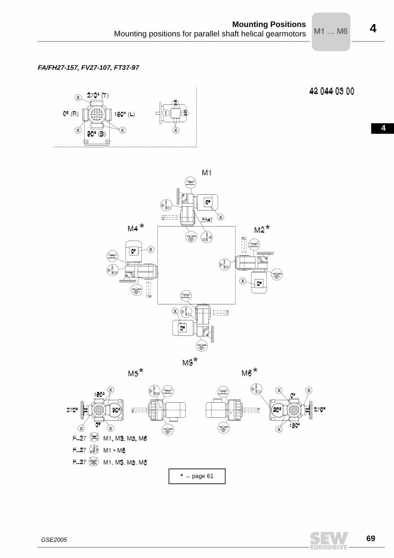
FA/FH27-157, FV27-107, FT37-97
* → page 61
M1 … M6M1 … M6

70 GSE2005
4 Mounting positions for helical-bevel gearmotorsMounting Positions
4.6 Mounting positions for helical-bevel gearmotors
K/KA..B/KH37B-157B, KV37B-107B
* → page 61
Important: See the information in the "Gearmotors" catalog, section "Project Planning for Gear Units/Overhung and axial loads" (page 36).
M1 … M6M1 … M6

GSE2005 71
4
1
2
3
4
5
6
7
8
9
10
11
12
13
14
15
16
17
18
19
20
21
22
Mounting positions for helical-bevel gearmotorsMounting Positions
K167-187, KH167B-187B
* → page 61
Important: See the information in the "Gearmotors" catalog, section "Project Planning for Gear Units/Overhung and axial loads" (page 36).
M1 … M6M1 … M6

72 GSE2005
4 Mounting positions for helical-bevel gearmotorsMounting Positions
KF/KAF/KHF/KAZ/KHZ37-157, KVF/KVZ37-107
* → page 61
M1 … M6M1 … M6

GSE2005 73
4
1
2
3
4
5
6
7
8
9
10
11
12
13
14
15
16
17
18
19
20
21
22
Mounting positions for helical-bevel gearmotorsMounting Positions
KA/KH37-157, KV37-107, KT37-97
* → page 61
M1 … M6M1 … M6
74 GSE2005
4 Mounting positions for helical-bevel gearmotorsMounting Positions
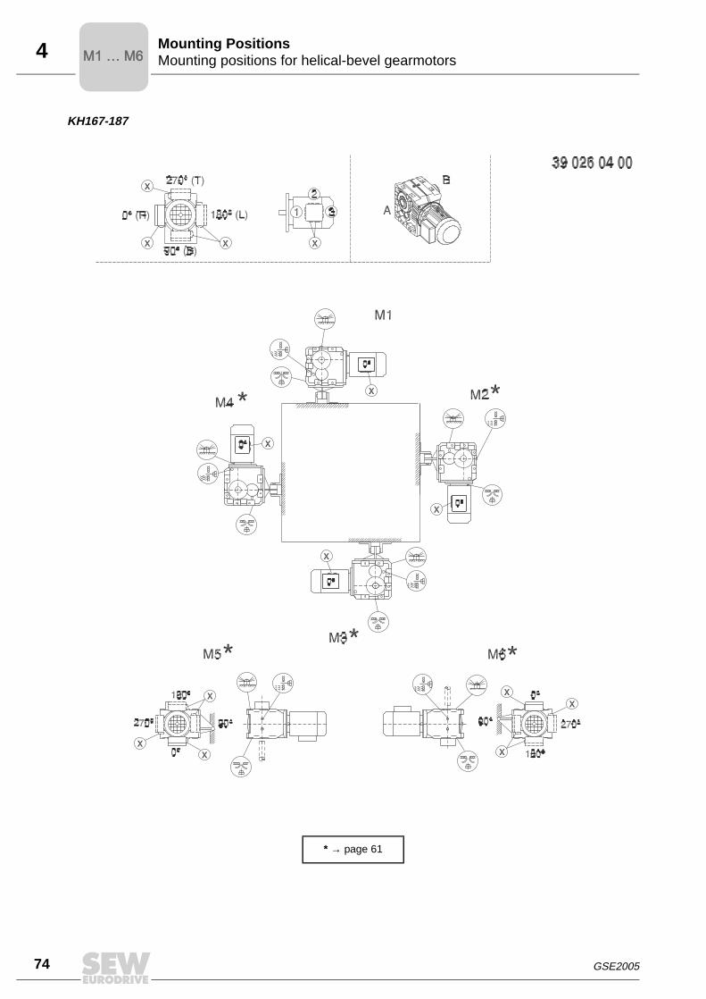
KH167-187
* → page 61
M1 … M6M1 … M6
GSE2005 75
4
1
2
3
4
5
6
7
8
9
10
11
12
13
14
15
16
17
18
19
20
21
22
Mounting positions for helical-worm gearmotorsMounting Positions
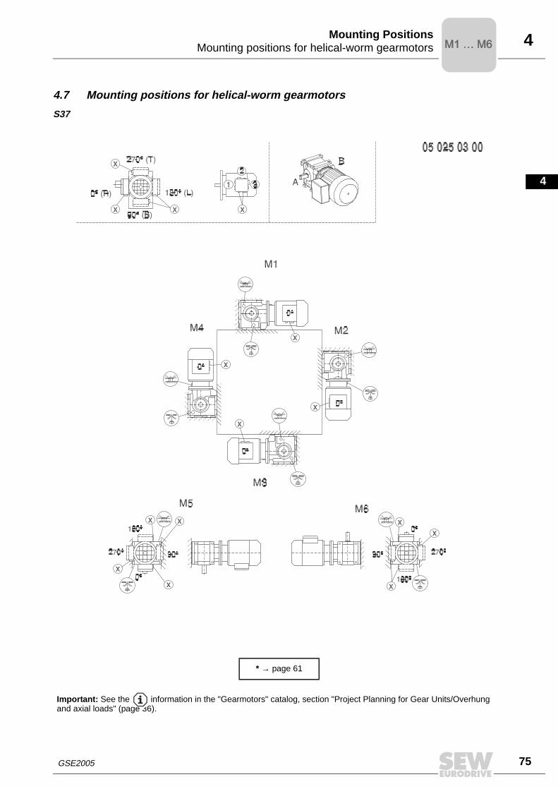
4.7 Mounting positions for helical-worm gearmotors
S37
* → page 61
Important: See the information in the "Gearmotors" catalog, section "Project Planning for Gear Units/Overhung and axial loads" (page 36).
M1 … M6M1 … M6

76 GSE2005
4 Mounting positions for helical-worm gearmotorsMounting Positions
S47-S67
* → page 61
Important: See the information in the "Gearmotors" catalog, section "Project Planning for Gear Units/Overhung and axial loads" (page 36).
M1 … M6M1 … M6
GSE2005 77
4
1
2
3
4
5
6
7
8
9
10
11
12
13
14
15
16
17
18
19
20
21
22
Mounting positions for helical-worm gearmotorsMounting Positions
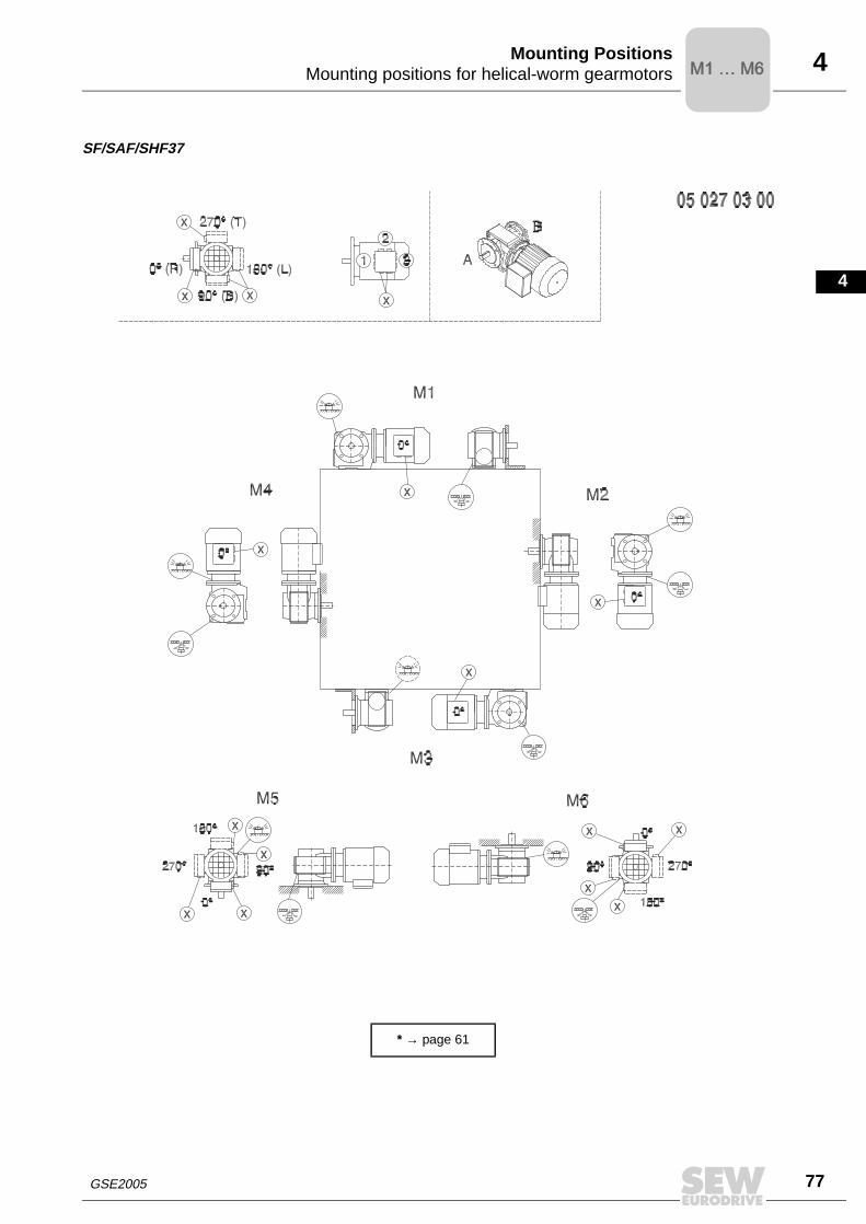
SF/SAF/SHF37
* → page 61
M1 … M6M1 … M6

78 GSE2005
4 Mounting positions for helical-worm gearmotorsMounting Positions
SF/SAF/SHF/SAZ/SHZ47-67
* → page 61
M1 … M6M1 … M6

GSE2005 79
4
1
2
3
4
5
6
7
8
9
10
11
12
13
14
15
16
17
18
19
20
21
22
Mounting positions for helical-worm gearmotorsMounting Positions
SA/SH/ST37
* → page 61
M1 … M6M1 … M6

80 GSE2005
4 Mounting positions for helical-worm gearmotorsMounting Positions
SA/SH/ST47-67
* → page 61
M1 … M6M1 … M6


![AIRFLOW Ceiling Mounting · wall mounting, [See: Installation diagram]. Spot through three fixing hole positions in skirt. Drill holes suitable for wall plugs supplied in the fixing](https://img.dokumen.tips/doc/110x75/5e90d7d5a028ed4cf70a2817/airflow-ceiling-mounting-wall-mounting-see-installation-diagram-spot-through.jpg)


