Embed Size (px)
Citation preview

4 I
9- C4Al
A I~4i. , - - i /
I
At-cd A&7b;7xC dAce CA I/kM
493a e/3a s/f/a/,
HOLE HISTORY
ROTARY HOLE DC-5
HANFORD, WASHINGTON
FEBRUARY, 1978
Prepared for Rockwell Hanford Operations,A Prime Contractor to the U. S. Department of Energy,
Under Contract Number EY-77-C-06-1030
by
FENIX & SCISSON, INC.HANFORD OPERATIONS BRANCH
RICHLAND, WASHINGTON 99352Under U. S. Department of EnergyContract Number EY-76-C-05-2175
N 0 T I C E
This report was prepared as an account of work sponsored bythe United States Government. Neither the United States,nor the United States Department of Energy, nor any of theiremployees, nor any of their contractors, subcontractors, ortheir employees, makes any warranty, express or implied, orassumes any legal liability or responsibility for theaccuracy, completeness, or usefulness of any information,apparatus, product or process disclosed, or represents thatits use would not infringe privately owned rights.
PDR WASTE IWm1-lo PDR A I PRS FILE COPY
iaf( w-4Vr

2 RHO-BWI-C-7
TABLE OF CONTENTS
Pace
INTRODUCTION 3
SUMMARY 3
DRILLING CHRONOLOGY 7
GEOLOGICAL SUMMARY 13
DISTRIBUTION 26
FIGURES
FIGURE 1 SITE MAP FOR HOLE DC-5 AT SITE 1 14
FIGURE 2 DRILLING PROGRESS CURVE HOLE DC-5 15
FIGURE 3 AS-BUILT DIAGRAM HOLE DC-5 16
TABLES
TABLE I DEVIATION SURVEYS 17
TABLE II CASING TALLY - AS-BUILT 13-3/8-INCH SURFACE CASING 18
TABLE III DESIGN CRITERIA FOR 13-3/8-INCH SURFACE CASING 19
TABLE IV CEMENTING DETAILS 20
TABLE V MUD RECORD 21
TABLE VI DESIGN CRITERIA FOR 9-5/8-INCH LONGSTRING CASING 22
TABLE VII CASING TALLY - AS-BUILT 9-5/8-INCH LONGSTRING CASING 23
TABLE VIII BIT RECORD 24
TABLE IX SERVICE COMPANIES AND EQUIPMENT SUPPLIERS 25

3 RHO-BWI-C-7 ' '
INTRODUCTION
Borehole DC-5 was drilled by Century Drilling Company, Shelby, Montana,
under subcontract to Fenix & Scisson, Inc. The hole was drilled for the
U.S. Department of Energy and the Rockwell Hanford Operations' Departmentof Waste Isolation. Fenix & Scisson, Inc. furnished the engineering, daily
supervision of the drilling activities and geological analysis of cuttings
from DC-5.
The purpose of hole OC-5 was to drill through the Umtanum basalt flow
to provide a borehole for hydrological testing, seismic shear and pressure
wave velocity studies and geophysical-electrical logging measurements of
the strata penetrated for the Basalt Waste Isolation Program.
Hole DC-5 is located at Site 1 as depicted on Figure 1. Drilling
commenced December 10, 1977 and the demobilization began February 10, 1978.
The drilling progress curve for DC-5 is shown in Figure 2. The total depth
of DC-5 is 3,990 feet. The open hole diameter is 8-5/8 inches and extends
1,355 feet from the longstring casing depth of 2,635 feet. Figure 3 is the
As-Built Diagram of Hole DC-5.Borehole DC-5 was completed successfully with an inflatable packer set
at 3,770 feet. The packer was set to isolate an aquifer zone at 3,340 feet
from a lost circulation zone at 3,954 feet. The packer is suspended on 2-7/8-
inch diameter tubing. A split cap plate was welded to the tubing and the
9-5/8-inch diameter casing. Hydrological testing and various logging measure-
ments are to be conducted at a later date.
SUMMARY
Century Drilling Company utilized rotary Rig Number 1 - Brewster ModelN-4A for drilling and construction of borehole DC-5. Mobilization of the
rig to DC-5 began December 7, 1977. A 26-inch diameter conductor hole was
spudded December 10, 1977. One joint (42 feet) of 20-inch diameter conductorcasing was set and cemented with 80 cubic feet of Type II cement containing
2 percent calcium chloride.
A surface hole diameter of 17-1/2 inches was drilled from 42 feet to
635 feet. The deviation of the borehole from vertical at 63.5 feet was1/2 degree. Table I lists the depths and deviation surveys performed during
the drilling of DC-5.

4 RHO-BWI-C-7
Surface casing, 13-3/8-inch outside diameter, was set at 622 feet. The
as-built tally for the surface casing is presented in Table II. The design
criteria for the surface casing are shown in Table III. The initial cementation
of the surface casing was interrupted after 300 cubic feet of cement had been
pumped into the casing. The interruption was caused by the cementing sub-
contractor's equipment malfunctioning. The cement was washed out of the
casing and the subcontractor's equipment was replaced.
The casing was cemented to surface with Class B cement containing 2
percent calcium chloride. The cementing and displacement details are presented
in Table IV. The total cement volume, 792 cubic feet, was circulated into the
casing annulus by the single stage, positive displacement-plug bump method with
610 cubic feet of displacement fluid.
A 12-1/4-inch diameter hole was drilled from the surface casing on December
18, 1977 with a bentonite base mud system. The record of the daily mud prop-
erties is presented in Table V. At 912 feet, complete lost circulation of the
drilling fluid occurred in a permeable zone while drilling. All normal methods
(polymer-particulate plugs and kwik-seal type plugs) to stop circulation were
unsuccessful. The drilling rig shut down December 22, 1977 in observation of
the holidays.
Rig operations were restored December 30, 1977. The drill string was struck
at 780 feet upon tripping in the hole. A total volume of 4,700 gallons of diesel
oil was spotted to free the stuck pipe. Lost circulation occurred when the
drill pipe was tripped to total depth. Several lost circulation pills with a
volume of 4,200 gallons each were spotted at 912 feet. Loss of circulation
returns continued to be observed at 912 feet. The cementing subcontractor
pumped 220 cubic feet of Type II cement containing 20 percent gilsonite and 3
percent calcium chloride. The cement was pumped through the drill pipe spotted
at 912 feet. Twelve hours were alloted for cement setting time. Upon tripping
in the hole, the cement top was found at 911 feet.
The 12-1/4-inch diameter hole was drilled to 924 feet where lost circulation
was observed. The cement subcontractor pumped 205 cubic feet of cement con-
taining 4 percent calcium chloride. The cement was pumped through the drill
pipe spotted at 915 feet. The cement set for eight hours. The cement top
was found at 851 feet. The cement was drilled and circulated from the hole.
No circulation loss was observed.
The 12-1/4-inch hole was drilled to 2,635 feet. No significant hole problems
were encountered from 924 feet to 2,635 feet. Sixty-five joints of 9-5/8-inch

5 RH0-BWI-C-7 .
diameter casing were run. The design criteria of the 9-5/8-inch longstring
casing are shown in Table VI. The as-built tally for the longstring casing is
presented in Table VII.
Initial cementation of the 9-5/8-inch casing occurred on January 21, 1978.
A total volume of 1,032 cubic feet of Class B cement containing 2 percent
calcium chloride was circulated into the casing. After 264 cubic feet of
displacement fluid had been circulated into the casing, the annulus bridged.
All attempts to jar the casing and to re-establish circulation were futile.
The cement remaining inside the casing was washed out.
Schlumberger Well Services, Inc. was contacted to run a cement bond log.
From the results of the bond log millivolt amplitude and the Murray Waves on
the variable density log, the uppermost competent casing to cement to formation
bond was at 2,280 feet. The casing was subsequently perforated with six 1/2-
inch diameter shaped charges from 2,270 to 2,276 feet.
The cementing head for the 9-5/8-inch casing was screwed on to the casing.
Circulation was attempted to a maximum applied surface pressure of 2,200 pounds
per square inch. Circulation was not established.
A compensated neutron log was run so that the exact locations of the
formations could be determined from the porosity index. Seven shaped charges,
1/2 inch in diameter; were used to perforate the casing from 1,756 to 1,762
feet. The perforated interval was chosen primarily for two reasons. First,
the compensated neutron log indicated the deepest interbed was the Mabton from
1,382 to 1,508 feet. As such, by perforating below the deepest water-bearing
interbed, if cementation through the perforations were successful, ample cement
would exist in the annulus to prevent water from circulating between porous
zones penetrated by the borehole. The second reason for selecting the 1,756
to 1,T62 foot interval was determined from the bond log and variable density
log. The bond log maximum millivolt amplitude indicated totally unsupported
casing through this interval. The variable density log had a total lack of
Murray Wave activity on the microsecond recording which indicates total lack
of formation bonding throughout the annular space.
The cementing head was connected to the casing and circulation was attempted.
Circulation was established initially at 400 pounds per square inch applied
surface pressure. However, no fluid returns were observed from the annulus at
surface. The circulating pressure stabilized at 175 pounds per square inch
for five minutes. Cement was pumped until the circulating pressure suddenly
I

I 6 RHO-BWI-C-7
increased to 2,600 pounds per square inch. Displacement of the cement with
water was attempted. After the displacement of 17 cubic feet of water into
the casing, the applied circulating pressure increased to 3,200 pounds per
square inch. The cement, 342 cubic feet of Class B with 2 percent calcium
chloride, was washed out of the casing.
Schlumberger Well Services, Inc. perforated seven 1/2-inch diameter holes
with shaped charges from 1,586 to 1,592 feet. The perforated interval was
chosen for the same reasons stated above for the 1,756- to 1,762-foot perfora-
tion interval.
Circulation was established with 100 pounds per square inch applied sur-
face pressure. Full circulating returns were observed at the surface from
the annulus. Cement was pumped into the casing. The cement volume was 660
cubic feet and the cement type was Class B with 2 percent calcium chloride.
The wiper plug was dropped and displaced with 645 cubic feet of water.
Approximately 45 cubic feet of cement were displaced to the reserve pit.
The details of the two unsuccessful and the last successful cementing and
displacement programs are presented in Table IV.
The cement was allowed to set seven hours. The cement top was found at
a depth of 1,545 feet inside the casing. The cement was drilled out of the
casing from 1,545 to 1,810 feet. A temperature log was run to check for
thermal variance caused by the heat of hydration of the cement. Due to the
high temperature of the water (high temperature caused by rig boiler) which
was used to drill through the cement in the casing, several hours were allowed
for the temperature to stabilize. A second temperature log and a cement bond
log were run. The bond log did not display conclusive bonding because of in-
adequate time for the cement to set up (a minimum of 36 to 48 hours is generally
required to achieve bonding capable of being recorded). The temperature log,
however, demonstrated significant increases from 1,760 to 1,670 feet and from
1,580 feet to surface. Since the temperature gradient from 2,635 feet to
surface does not normally demonstrate variational increases, the significant
increases are attributed to the heat of hydration of the cement.
An 8-5/8-inch diameter hole was drilled from the longstring casing at
2,635 feet. Water was utilized as the drilling fluid from 2.635 to 3 9
feet. At 3,340 feet, water was observed flowing from the annulus (between
drill pipe and casing) during a drill pipe connection. The rate of water '
flowwas_ e-stimatedto be 12 gallons per minute. The water flow continued
during trips and connections when the circulating pump was not engaged. \
._ . . . . . And.,?~~~~1{~ (

7 RHO-BWI-C-7 .
Between 3,400 and 3,700 feet, the deviation of the hole increased from
1-3/4 to 4-1/4 degrees. Additional stabilizers were placed in the bottom holeassembly and the stabilizer positions were changed. The packed bottom hole
assembly was used to ream through the deviated hole section from 3,400 to
3,700 feet.
At a drill depth of 3,954 feet, lost circulation was observed. Particu-
late lost circulation material in the form of ground nut shells was spotted.
Drilling continued to the total depth of 3,990 feet with partial circulation
returns. Total depth was reached on February 7, 1978. A packer was set at
3,770 feet to prevent cross flow between a flowing zone at 3,340 feet and a
lost circulation zone at 3,954 feet. The packer was an inflatable production
type with a J-type circulating head. The packer is suspended on 2-7/8-inch
tubing. A cap split plate was welded to the 2-7/8-inch tubing and the 9-5/8-inch
casing head.
The tri-cone bits used to drill hole DC-5 and the record of their perform-
ance are presented in Table VIII. The 26-inch diameter conductor hole was
drilled with a standard-tooth type bit. The ten other bits used for drilling
were tungsten carbide chisel-tooth insert type bits. The tungsten carbide
bits averaged more than 390 feet drilled per bit.
The service companies and equipment suppliers who participated in the
successful drilling of hole DC-5 are listed in Table IX.
DRILLING CHRONOLOGY
12-07-77 - Mobilizing rig to DC-5 location from DC-7 site.
12-08-77 - Mobilization completed; rig-up.
12-09-77 - Completed rig-up; drilled rat hole.
12-10-77 - Drilled mouse hole; drilled 26-inch conductor hole to 17 feet.
12-11-77 - Conductor hole drilled to 42 feet; ran one joint of 20-inch
conductor casing; cemented conductor casing with 80 cubic feet
of Type II cement containing 2 percent calcium chloride; picked
up 17-1/2-Inch bottom hole assembly; waited on cement 11-1/2
hours.
12-12-77 - Began drilling 17-1/2-inch hole at 0030 hours; drilled to 128
feet; survey at 85 feet = 1/2 degree from vertical.
1..

8 8 ~~~~~~~RHO-BW! -C-7
12-13-77 - Drilled 17-1/2-inch hole to 245 feet; cemented top of 20-inch
conductor pipe with 3 sacks of neat cement; survey at 206 feet =
1/4 degree.
12-14-77 - Drilled 17-1/2-inch hole to 388 feet; survey at 368 feet = 0 degree.
12-15-77 -
12-16-77 -
12-17-77 -
12-18-77 -
12-19-77 -
12-20-77 -
12-21-77 -
12-22-77 -
12-30-77 -
Drilled 17-1/2-inch hole to 593 feet; trip for balled bit at
510 feet; 85 feet of bottom hole fill; survey at 552 feet = 1/2
degree.
Drilled 17-1/2-inch hole to 635 feet; circulated bottoms up;
tripped out to run 13-3/8-inch surface casing; ran 622 feet of
13-3/8-inch casing; pumped 300 cubic feet of Class B cement with
2 percent calcium chloride - both cementing pumps stopped operating;
displaced cement from casing and annulus; waited on new pump truck.
Waited on cement pump truck; circulated complete hole cycle every
six hours.
Cement pumper and bulk truck arrived at 0330 hours; pumped 600
sacks of Class B cement with 2 percent calcium chloride; displaced
cement with 610 cubic feet of water - plug bumped at 0500 hours;
waited on cement to set; cut casing up on last joint and nippled
up blowout preventer; drilled 12-1/4-inch hole to 638 feet. -
Drilled 12-1/4-inch hole to 668 feet; survey at 663 feet = 3/4
degree; trip out to check collars.
Drilled 12-1/4-inch hole to 733 feet; trip to check bit at 678
feet; survey at 710 feet = 3/4 degree.
Drilled 12-1/4-inch hole to 870 feet; survey at 867 feet = 1/2
degree.
Drilled 12-1/4-inch hole to 912 feet; lost circulation; short
trip - spotted lost circulation material;,200 feet of bottomhole fill; washed through fill; lost returns; spotted second
100-barrel pill; drained pits; pulled up into casing; closed
pipe rams; shut down for Christmas holidays.
Rig-up - started boiler; mix mud and lost circulation material;trip out for bit; trip in; drill string stuck in the hole at 780
feet; spotted 1,900 gallons of diesel oil - worked pipe.

9 RHO-BSWI-C-7 -
12-31-77 -
1-01-78 -
1-02-78 -
1-03-78 -
1-04-78 -
1-05-78 -
1-06-78 -
1-07-78 -
1-08-78 -
1-09-78 -
1-10-78 -
Spotted 2,800 gallons of diesel and organic mud lubricant - worked
pipe; pipe free; circulated hole clean; washed to 880 feet.
Washed - reamed hole to total depth; lost circulation; trip out
to casing shoe; spot 100-barrel lost circulation pill; waited 4
hours, attempted to circulate; spotted second pill - no returns;
trip in to 912 feet; spotted lost circulation material pill; trip
out 6 stands; broke circulation; trip in-stage circulating; lost
returns at 912 feet.
Short trip up to casing shoe; mix high lime lost circulation
pill; spotted pill; mixed mud and lost circulation material;
pumped mud with 20 percent particulate lost circulation material;
trip out - lay down drill collars; trip in with drill pipe; wait
on cementers.
Wait on cementers; trip drill pipe out; trip in 1 stand of collars
and drill pipe; stage circulation attempted every stand; drilled
12-1/4-inch hole to 920 feet; trip out; trip in with drill pipe;
spotted 220 cubic feet of Type II cement with 20 percent gilsonite
and 3 percent calcium chloride; trip out.
Trip in; mix mud. and lost circulation material; tagged cement at 911
feet; drilled 12-1/4-inch hole 920 to 924 feet; lost returns;
pumped 205 cubic feet of Type II cement with 4 percent calcium
chloride; wait on cement; trip in - tagged cement at 851 feet.
Drilling cement from 851 feet to 924 feet; drilled 12-1/4-inch
hole to IiO16 feet; survey at 992 feet = 1 degree.
Drilled 12-1/4-inch hole to 1,102 feet; survey at 1,085 feet =
3/4 degree.
Drilled 12-1/4-inch hole to 1,231 feet; survey at 1,180 feet =
0 degree.
Drilled 12-1/4-inch hole to 1,303 feet; survey at 1,243 feet =
1/2 degree.
Drilled 12-1/4-inch hole to .1,370 feet; trip for bit; tight hole
to bottom of casing; survey at 1,369 feet = 3/4 degree.
Drilled 12-1/4-inch hole to 1,508 feet; survey at 1,494 feet
3/4 degree.
10 RHO-B'WI -C-7
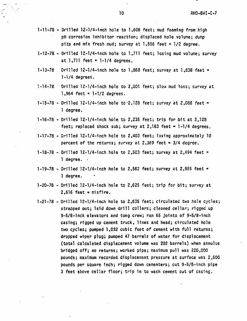
1-11-78 -
1-12-78 -
Drilled 12-1/4-inch hole to 1,606 feet; mud foaming from high
pH corrosion inhibitor reaction; displaced hole volume; dump
pits and mix fresh mud; survey at 1,556 feet = 1/2 degree.
Drilled 12-1/4-inch hole to 1,711 feet; losing mud volume; survey
at 1,711 feet = 1-1/4 degrees.
1-13-78 Drilled 12-1/4-inch hole to 1,868 feet; survey at 1,838 feet =
1-1/4 degrees.
1-14-78 Drilled 12-1/4-inch hole to 2,001 feet; slow mud loss; survey at
1,964 feet = 1-1/2 degrees.
1-15-78 -
1-16-78 -
1-17-78 -
1-18-78 -
1-19-78 -
1-20-78 -
1-21-78 -
Drilled 12-1/4-inch hole to-2,128 feet; survey at 2,088 feet =
1 degree.
Drilled 12-1/4-inch hole to 2,235 feet; trip for bit at 2,128
feet; replaced shock sub; survey at 2,183 feet = 1-1/4 degrees.
Drilled 12-1/4-inch hole to 2,403 feet; losing approximately 10
percent of the returns; survey at 2,369 feet = 3/4 degree.
Drilled 12-1/4-inch hole to 2,503 feet; survey at 2,494 feet =
I degree.
Drilled 12-1/4-inch hole to 2,562 feet; survey at 2,555 feet =
1 degree.
Drilled 12-1/4-inch hole to 2,625 feet; trip for bit; survey at
2,616 feet = misfire.
Drilled 12-1/4-inch hole to 2,635 feet; circulated two hole cycles;
strapped out; laid down drill collars; cleaned cellar; rigged up
9-5/8-inch elevators and tong crew; ran 65 joints of 9-5/8-inch
casing; rigged up cement truck, lines and head; circulated hole
two cycles; pumped 1,032 cubic feet of cement with full returns;
dropped wiper plug; pumped 47 barrels of water for displacement
(total calculated displacement volume was 202 barrels) when annulus
bridged off; no returns; worked pipe; maximum pull was 220,000
pounds; maximum recorded displacement pressure at surface was 2,500
pounds per square inch; rigged down cementers; cut 9-5/8-inch pipe
3 feet above cellar floor; trip in to wash cement out of casing.

RHO-BWI-C-71 1
1-22-78 -
1-23-78 -
1-24-78 -
1-25-78 -
1-26-78 -
Tagged cement at 560 feet; drilled wiper plug and cement to
2,635 feet.
Circulated hole; waited on Schlumberger Well Services, Inc.;
ran bond log; waited on welder to weld collar on pipe for cement
head connection.
Welded collar on 9-5/8-inch casing; perforated 6 half-inch holes
at 2,276 feet; attempted to circulate; no circulation with 2,200
pounds per square inch surface pressure; wait on orders.
Wait on orders; ran neutron log; perforated 7 half-inch holes,
at 1,760 feet; rig up cementing head; broke circulation with 400
pounds per square inch, no returns to surface; pumped 342 cubic
feet of cement - circulating pressure increased to 2,600 pounds per
square Inch; attempted to displace cement from casing - maximum
pressure increased to 2,600 pounds per square inch; re-rack pipe
in derrick; nippled up to wash cement out of casing.
Washed cement out of casing; rigged up Schlumberger Well Services,
Inc.; perforated 7 half-inch holes at 1,590 feet; rigged up
cementing head; broke circulation with water at 100 pounds per
square inch; pumped 660 cubic feet of cement - maximum circulating
pressure was 800 pounds per square inch; dropped wiper plug; dis-
placed cement with 115 barrels of water; approximately 45 cubic
feet of cement displaced to reserve pit; back-off cement head;
nippled up blowout preventer; trip in; tagged cement at 1,545
feet; wait on cement; drilled cement to 1,810 feet; circulated
hole; trip out; ran temperature log.
1-27-78 - Completed temperature log, wait on orders; ran second temperature
log and cement bond log; drilled 8-5/8-Inch hole to 2,770 feet;
survey at 2,740 feet - 3/4 degree. fluid loss of 25 barrels of
-water per our.
1-28-78 - Drilled 8-5/8-inch hole to 2,988 feet; lost 15 to 25 barrels of
water per hour; survey at 2,929 feet = 3/4 degree.
1-29-78 - Drilled 8-5/8-inch hole to 3,168 feet; survey at 3,115 feet =
1-1/4 degrees.

12 RHO-BWI -C-7
1-30-78 - Drilled 8-5/8-inch hole to 3,248 feet; trip for bit; surveyat 3,239 feet = 1-3/4 degrees.
1-31-78 - Drilled 8-5/8 h hole to 3,449 feet; connection made-at. 3,340, feet, annulus was flowing water; survey at_3,428 feet.-=--3/.4-
degrees.
2-01-78 -
2-02-78 -
2-03-78 -
Drilled 8-5/8-inch hole to 3,630 feet; hole sloughed at 3,550feet; survey at 3,613 feet = 2-1/2 degrees.
Drilled 8-5/8-inch hole to 3,737 feet; dropped Totco instrument;trip out; picked up stabilizers; survey at 3,737 feet = 4-1/4degrees.
Trip in; tigt hole at 3,683 - stuck pipe; worked pipe free;reamed to total depth; drilled 8-5/8-inch hole to 3,780 feet;survey at 3,778 feet = 4-3/4 degrees.
2-04-78 - Drilled 8-5/8-inch hole to 3,851 feet; survey at 3,838 feet =
2-05-78 -
5 degrees.Drilled 8-5/8-inch hole to 3,930 feet; survey at 3,930 feet =5 degrees.
2-06-78 -
2-07-78 -
Drilled 8-5/8-inch hole to 3,976 feet; lost circulation at 3,954feet; trip out and remove jets; tgn Ls QedAJost
circulation material p ; regained partial circulation.
Drilled 8-5/8-inch hole to 3,990 feet; layed down drill pipe;tear down blowout preventer; wait on packer.
2-08-78 - Wait on packer.
2-09-78 -
2-10-78 -
Wait on packer; ran inflatable packer with J-type circulatinghead on 2-7/8-inch tubing; set packer at 3,770 feet; circulated300 barrels of calcium chloride water into annulus from packerhead to surface; start rig tear down.
Completed rig tear down; radiation monitoring cleared rig;demobilize.

13 RXO-BWI-C-7
GEOLOGICAL SUMMARY
The approximate depths and thicknesses of stratigraphic units penetrated
by hole DC-5 are shown on Figure 3.
Preliminary identification of stratigraphic units was accomplished by
microscopic examination of drill cuttings and by Energy Nondispersive X-ray
analysis of pulverized cuttings samples from the central portions of the basalt
flows. All major stratigraphic horizons, such as the titania and magnesia
breaks, were identified by the X-ray tests.
Preliminary determination of rock unit contacts was made by inspection of
the drilled cuttings, changes in drilling penetration rates (noting weight on
the bit) and observation of drill fluid loss. In many cases, the flow contacts
could not be precisely determined due to contamination of the cuttings from
overlying units and to misleading Geolograph drilling rate changes. Many of
the flow top breccias can be drilled at a similar rate of penetration as the
soft interbeds; hence, no drilling rate break would result until the bit reached
competenti basalt.
Compensated neutron logging of the upper portion of the hole, 0 to 2,634 feet,
confirmed the previously identified contacts generally within a few feet. Con-
firmation of flow contacts below 2,634 feet will be possible by inspection of
future geophysical logs planned for this hole and further verification of the
entire section penetrated will result from inspection of cores from the planned
nearby core hole DC-4.

14 RHO-B WI-C-7
.f
200E
RATTLESNAKE HILLS
0 5MILES
FIGURE 1SITE MAP FOR HOLE DC-5 AT SITE 1

I15 15 ~~~~~RHO-SWI-C-7
500
1 ,000
1,500
.iLA-
_ 2,000I-J
2,500
3,000
3,500
4,000
CUMULATIVE DAYS
FIGURE 2
DRILLING PROGRESS CURVE HOLE DC-5

* 16 RHO-BWI-C-7
DEPTHFEET
GROUND LEVEL:S-26"-Conductor Hole~-20" Conductor Casing
-17-1/2" Surface Hole
43-3/8" Surface Casing54.5#, J-55, R-3
1 ,01
1Intermediate Hole
Longstring Casing40#, J-55, R3
Open Hole
2,
3,1
3,
4,iFIGURE 3
AS-BUILT DIAGRAM HOLE DC-5
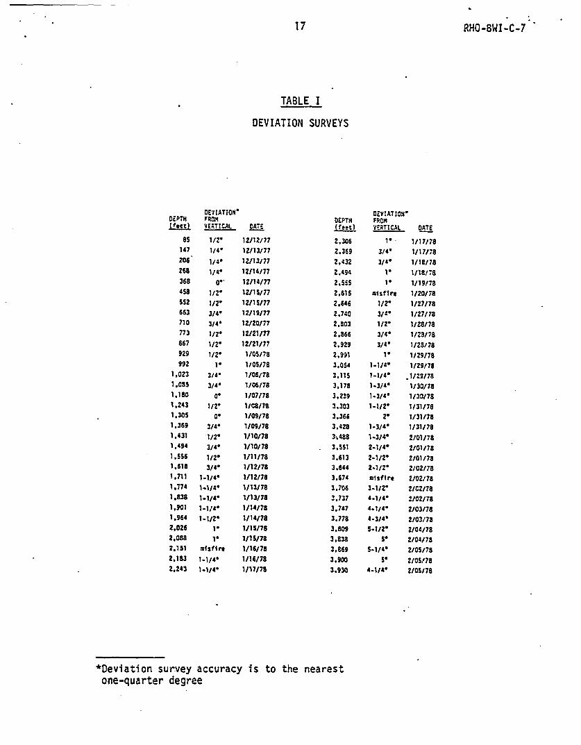
17 RHO-BWI-C-7
TABLE I
DEVIATION SURVEYS
DEVIATION*DEPTH FROM(feet) VERTICAL DATC
85 1/2' 12/12/77147 1/4' 12/13/77
206 1/4' 1Z/13/77268 1140 12/14177
368 O- 12/14/77
458 1/2- 12/15177
552 1/2r 12/15/M663 3/4' 12/19/77710 3/4* 12/20/77
773 112' 12/21/77867 1J2' 12/21/77
929 1/2' 1/05/78
992 le 1/05/78
1,023 3/4 1/06/781,09S 3/4. 1/06/781.180 a- 1/07/78
1.243 1/' W/OWS7
1.305 0' 1/09/78
1.369 3/4' 1/09/781.431 1/2' 1/10/781.494 3/4 1/10/78
1,556 1/2- 1/11/781.618 3/4' 1/12/781,711 1-1/4- 1/12/781,774 1-1/4' 1/13/78
1.838 1-1/4' 1/13/78
1,901 1-./44 1/14/78
1.964 111/2 1/14/78
2.026 1' 1/15/78
2,088 1' 1/1S/78
2.151 ;misfire 1/16/78
2.183 1-1/4' 1/16/78
2,243 1-1/4' 1/17/78
DEPTH(fet
2,3062,3692.432
2.494
2.5552.6162.46
2,740
2.S032.8662,929
2.991
3.054
3.115
3,1783.2393.303
3.3663.428
3.488
3,551
3,6133.6443.6743,7063,7373.747
3.778
3.809
3,8383,8693.900
3.930
DEVIATION'FRCHVERTICAL DATE
1- 1/17/78
3/4* 1/17/783/4" 1/18/781' 1/18/78
1- 1/19/78
misfire 1/20/78
1/2' 1/27/783/4" 1/27/781/2' 1/28/783/4' 1/23/783/4' 1/28/781' 1/29178
1-1/4' 1/29/78
1-1/4' .1/29/78
1-3/4' 1/30/78
1-3/4' 1/30/781-1/20 1/31/78
2' 1/31/781-3/4' 1/31/7a
1-3/4- 2/01/78
2-1/4' 2/01/78
2-1/2- 2/01/782-1/2' 2/02/78misfire 2/02/78
3-1/2' 2/G2/784-1/4' 2/02/78A.1/4. 2/03/78
4-3/4' 2/03/785-1/2' 2/04/78
5' 2/04/785-1/4' 2/05/78
5' 2/05V784-1/4' 2/OSI7S
*Deviation survey accuracy is to the nearestone-quarter degree

18 RHO-BWI -C-7
TABLE II
CASING TALLY - AS-BUILT 13-3/8-INCH SURFACE CASING
JOINTNUMBER
LENGTH(ft)
12345678
1.5042.1041.3441.1042.4241.9641.3542.6242.14
STRINGEQUIPMENT
Float ShoeStabilizer
Stabilizer
JOINTNUMBER
9101112131415
LENGTH(ft)
STRINGEQUIPMENT
41.0740.4240.8841.2341.3440.4240.59
TOTAL 622.48

RHO-BWI -C-7
TABLE III.
DESIGN CRITERIA FOR 13-3/8-INCH SURFACE CASING
SECTION .1...
WEIGHT(lb/grade)...... 54.5/J-55 ST&C
EFFECTIVECOLLAPSE*RESISTANCE(psi) . . . . .... 566
DEPTH OFBOTTOM OFSECTION(ft) .. . . . . . . . . . . . . . .622
LENGTH OFSECTION(ft) .. 622
CUMULATIVEEFFECTIVE WEIGHTTO TOPOF SECTION(lb) (*.......................... 33,899
USABLEJOINTSTRENGTH INTENSION(lb) ............................. 480,101
DEPTHTO TOP OFSECTION(ft) ........................... O-
BIAXIALSTRESS-COLLAPSESLOPE ......................... .... -89.31
*Collapse Criteria - 15.5 pounds per gallon cementexternal versus normal atmospheric pressure

20 RHO-BWI-C-7
TABLE IV
CEMENTING DETAILS
12-11-77 12-18-77 1-21-78 1-25-78 1-26-78
CASING SIZE (in.)
CASING DEPTH (ft.)
CEMENT UTILIZED
CEMENT VOLUME (cu.ft.)
DISPLACEMENT VOLUME (cu. ft.)
SLURRY YIELD (cu. ft/sack)
SLURRY WEIGHT (lb/gal)
ADMIXTURES
CEMENT METHOD t
CEMENT STAGES
WAIT ON CEMENT TIME (hr.)
20
620
Type II
81
83
1.18
15.6
2% CaCl
PositiveDisplacement
1
11.5
13-3/8
622
Class B
792
610
1.32
14.6-15.6
2X CaCl
PlugBump
1
I15
9-5/8
2,635
Class B
1032
264
1.32
15.2-15.6
20 CaCl
(AnnularBridge)
1
6
9-5/8
2,635
Class B
342
17
1.32
15.5
2X CaCl
(AnnularBridge)
1
4
9-5/8
2,635
Class B
660
645
1.32
15.2-15.6
2% CaCl
PositivePlug
Displacement
1
7

21 RHO-8WI-C-7
TABLE V
MUD RECORD
DATE* 1977
DEPTH(f t)
WEIGHT(lb/gal)
VISCOSITY GELSSec GY( SAPI PV YP (10 sec:10 min)
SANDOH I
SOL IDSO.)
12-11 4212-14 28612-16 62912-19 66212-20 67412-21 82312-22 89212-31 9121- 1 9121- 5 9231- 6 1050I- 7 11571-11 15571-12 16541-13 17841-15 20451-16 21421-17 22691-18 24491-19 25231-20 25761-22 to 2-9
8.5 768.8 SO8.7 758.5 378.6- 378.7 348.8 358.6 458.6 508.7 438.9 388.8 369.5 508.8 428.9 439.1 469.1 409.2 409.5 449.5 459.4 43
Fresh Water
16
161616161621
17152010101210
8128
18
6
1012
6121216
1312
8666664
124
7:12
3:114:122:83:165:164:12
6:182:164:103:94:116:126:157:134:114:113:9
8.5
9.59.79.59.5
. 99
11.59.58.58.58.58.588.58.58.58.5
2
.5
Is.171.51233431.5
8
7777
9710
45867987
I .

22 RHO-BWI-C-7
TABLE VI
DESIGN CRITERIA FOR 9-5/8- INCH LONGSTRING CASING
SECTION ...
WEIGHT(lb/grade) ....... 40/J-55 ST&C
EFFECTIVECOLLAPSE*RESISTANCE(psi) .... 446
DEPTH OFBOTTOM OFSECTION(ft) 2 , 63.. .25.... -
LENGTH OFSECTION(ft) .- 2,635
CUMULATIVEEFFECTIVE WEIGHTTO TOPOF SECTION(lb) ..................... ... 105,400
USABLEJOINTSTRENGTH INTENSION(lb) .346,600
DEPTHTO TOP OFSECTION(ft) . . . . . . . . . . . . . . . . . -O
BIAXIALSTRESS-COLLAPSESLOPE ...- 65.55
*Collapse Criteria - 15.5 pounds per gallon cementexternal versus normal atmospheric pressure
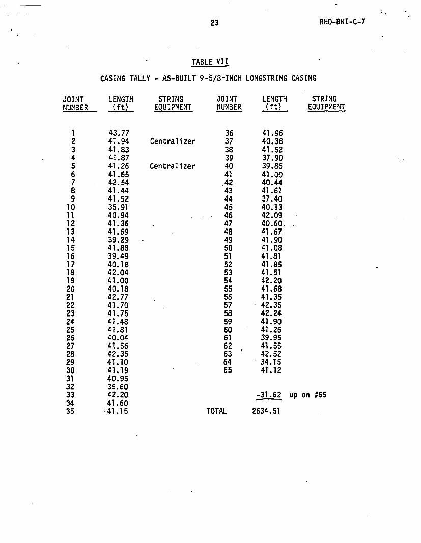
23 RHO-BWI-C-7
TABLE VII
CASING TALLY - AS-BUILT 9-5/8-INCH LONGSTRING CASING
JOINTNUMBER
LENGTH(ft)
STRINGEQUIPMENT
JOINTNUMBER
LENGTH(ft)
STRINGEQUIPMENT
12345678910
21
121314151617181920212223242526272829303132333435
43.7741.9441.8341.8741.2641.6542.5441.4441.9235.9140.9441.3641.6939.2941.8839.4940.1842.0441.0040.1842.7741.7041.7541.4841.8140.0441.5642.3541.1041.1940.9535.6042.2041.6041.15
Centralizer
Centralizer
363738394041.424344454647484950515253545556575859606162636465
41.9640.3841.5237.9039.8641.0040.4441.6137.4040.1342.0940.6041.6741.9041.0841.8141.8541.5142.2041.6841.3542.3542.2441.9041.2639.9541.5542.5234.1541.12
-31.62 up on #65
TOTAL 2634.51

TABLE VIII
BIT RECORD
FEET lITJET PER 1I000 PtP MUO Dtttt COlOITION
NOL SIIE WUE TYPE 32d IN DEPTH FEET JOURs HIDUR !js RP" PRESS WaT. Vhs- T a C1 U6 SIC Ds OPEN 42 42 19.5 2.1S 29 60 100 .1. 76 4 2 22 17.5 SiC 4JS OPEN 635 591 94. 5 6.25 10/1 60 5.1 15 6 6 53 12.25 Sic F-3 11-16-16 912 319 12.15 4.38 1535 60 650 8.8 35 6 S 44 12. 25 Sic F-4 OPEN 1327 415 07.5 4.74 9/35 60 100 9.2 40 7 S SS 12.2S Sic f-4 OPEN 2128 101 144.-25 5.5S 30/3S 60 1001200 9.1 40 7 1 16 12.25 SiC r-4 22-22-22 2517 449 94 4.71 3S/318 60 100/400 9.4 43 7 1 57 12.25 SiC F-4 22-22-22 263S 58 12.75 4.54 20/38 60 250/300 9.2 47 3 2 1a 0.626 REED 4-13 13-13-13 2635 2011 23 90.21 30/38 60 3001900 WATER OR.. CENT9 8.625 REED Fr-72 14-14-14 3226 591 13.15 8.01 20/40 60 100/800 YAlER S 5 410 8.625 REEP FP-72 14-14-14 3731 Sit 63.25 3.01 10/40 60 700 VEIER 5 S 611 0.6.5 *EEO FP-72 14-14-14 3989 252 79.25 3.11 5/20 60 325/675 VAIER 4 3 4
STC'Salth Tool Coa y 1
T = Tooth
B Bearing
G = GaugeDull Condition Grading System utilized is that of the International Associationof Drilling Contractors.
0
* .w~~~~~~~~~~~~~~~~~~~~~~~~~~~~~~~~~~~~~~~~~~~~~~~~~~~~

25 25 ~~~~~RHO-BWI-C-7
TABLE IX
SERVICE COMPANIES AND EQUIPMENT SUPPLIERS
Ace Sales & Services, Inc., Richland, Washington - sanitary facilities
Big Chief Water Services, Inc., Shelby, Montana - water transporting
Bill's Casing Tong Service, Marysville, California - tong service
Christensen Diamond Products U.S.A., Inc., Casper, Wyoming - stabilizerand shock-sub
Dahlory, Inc., Santa Fe Springs, California - shale shaker
Drilling Fluid Specialists, Inc., El Segundo, California - mud productsand services
Fleet Cementers, Inc., Grand Junction, Colorado - cement productsand services
Gulco Industries, Inc., Oklahoma City, Oklahoma - well head equipment
Herman Karst Enterprises, Inc., Casper, Wyoming - conductor casing
J. A. Jones Construction Compnay, Richland, Washington - site construction
Lynes, Inc., Bakersfield, California - PIP packer and circulating head
Monarch Machine Shop, Pasco, Washington - cap plate
National Supply Company, Casper, Wyoming - casing
Redman Pipe and Supply, Inc., Tulsa, Oklahoma - well head equipment
Reed Tool Company, Inc., Houston, Texas - bits
Rucker-Acme Tool Company, Casper Wyoming - blowout preventer and drill collar rental
Schlumberger Well Services, Inc., Cut Bank, Montana - logging and perforating services
Smith Tool Company, Inc., Houston, Texas - bits
Western Building Supply Company, Pasco, Washington - cement admixtures

I em_t
1,:
25 RHO-BWI-C-7
DISTRIBUTION
Number ofCopies
10
4
FENIX &
B. S.
J. B.G. C.
PACIFIC
SCISSORi, IN:C.
Carson (2) EDunn/TulsaGibbs/Tulsa fMathis
NORTHWEST LABORATORY
3. E. Russell (2)J.-E. Tyner.'LS Richland Operations Library (2)
37
1
*1
2
1
1
T. W. AmbroseJ. R. EliasonA. M. PlattR. W. Wallace
ROCKWELL HANIFORD OPERATIOIS
R. L. Bi~gqger-vwT. A. CurrainH. B. DietzG. C. Evans
A. D. KrugJ. F. Marron(nMS-Tft1-aste Isolation ProgramLibrary (25)Document Control (4)
U. S. ARMY CORPS OF ENGIIEERS
Walla Walla Uistrict Geologist
U. S. BUREAU OF RECLAMATION
Columbia Basin Project Geologist
U. S. DEPARTHErT OF EHERGY-ALBUOUERQUE OPERATIONS OFFICE
D. DavisD. T. Schueler
U. S. DEPARTMENT OF EIIERGY-COLUMBUS PROGRAM OFFICE
J. Neff
U. S. DEPARTMEiIT OF ENJERGY-HEADOUARTERS
1
D. L. Vieth
U. S. DEPARTMIENIT
D. G. Jackson
OF ENERGY-NEVADA OPERATIONS OFFICE

e_-
27 RHO-SWI-C-7
Number ofCooies
5 U. S. DEPARTMEIUT OF ErJERGY-RICHLAil1 OPERATIOIIS OFFICE
R. E. ConeJ. C. CurimningsR. B. GoransonA. G. Lassila0. J. Squires
2 OTHERS
J. F. T. AgapitoColorado School of lines