Embed Size (px)
Citation preview

RLH Industries, Inc. • Tel. 866-DO-FIBER • Fax 714 532-1885 • www.fiberopticlink.com Page �1
4 Channel Contact Closure SFPDIN Fiber Link System Installation and Configuration Information
Description The system provides transmission of four (4) independent input signals over fiber optic cable. Applications include alarm event triggering, building automation, environmental control systems, fire & alarm systems, gate control, traffic signal control equipment, and more.
Fiber optic cable is immune to RF noise, EMI, high voltages, and may extend the signal up to 100km. A complete system requires a Transmitter and Receiver, a 24-48VDC power source, and a compatible SFP transceiver for the fiber interface.
Each unit features a wide operating temperature, redundant power terminals, and a system alarm contact for monitoring the unit for proper operation. LED indicators provide a convenient view of the systems current status. This hardened system can be wall or DIN rail mounted with the included DIN clip and wall mount ears, is made in the USA, and backed by our limited lifetime warranty.
Contact Input - Transmitter Device The input terminals have the ability to sense 4 independent inputs. The dry contact model makes installation of the unit quick and simple. Wet contact models have the ability to receive an input signal between 5~12VDC or 24~48VDC.
Contact Output - Receiver Device Each receiver device is paired with a transmitter on the opposite end of the system. The relays will be factory set to Normally Open or Normally Closed and for both these options the switching power is rated at 60Watts (DC or AC).
U-132 2017A-0707
4 Channel Contact Closure SFP System
Standard Features
4 independent input signals over fiber
Convenient LED status indicators
Supports SFP Transceivers
Inputs either sense a dry contact or receive a voltage
Each input terminal is optically isolated, 3.5kV
Each output rated to support a load up to 60 Watts
Redundant power inputs (24-48VDC)
Pluggable terminal blocks
Alarm contact for status monitoring
Environmentally rugged with wide operating temp. -40˚F to +158˚F (-40˚C to +70˚C)
Standard T35 DIN rail and walll mount applications
Designed and Made in the U.S.A.
The leader in rugged fiber optic
technology.USER GUIDE
RLH Industries, Inc.

General Safety Practices The equipment discussed in this document may require tools designed for the purpose being described. RLH recommends that service personnel be familiar with the correct handling and use of any installation equipment used, and follow all safety precautions including the use of protective personal equipment as required.
Caution - Severe Shock Hazard• Never install during a lightning storm or where unsafe high voltages are present. • Use caution when handling copper wiring and follow appropriate safety regulations.
Guidelines for Handling Terminated Fiber Cable
!
• Do not bend fiber cable sharply. Use gradual and smooth bends to avoid damaging glass fiber. • Keep dust caps on fiber optic connectors at all times when disconnected. • Do not remove dust caps from unused fiber. • Keep fiber ends and fiber connectors clean and free from dust, dirt and debris. Contamination will cause
signal loss. • Do not touch fiber ends. • Store excess fiber on housing spools or fiber spools at site
Acronyms Commonly used acronyms and abbreviations
Acronym/Abbreviation DescriptionTX TransmitRX Receive
PWR Power
CH The logical connection between inputs and outputs
SFP Small Form-factor Pluggable TransceiverDRY Input does not require voltage to sense a dry contact
WET Input expects DC Voltage IN
Digital Input An ON or OFF (1 or 0)
NO Normally Open
NC Normally Closed
Page � RLH Industries, Inc. • Tel. 866-DO-FIBER • Fax 714 532-1885 • www.fiberopticlink.com2

Applications By utilizing fiber optic cable, the 4 Channel Contact Closure DIN Fiber Link system provides absolute electrical isolation between both ends of the network. It is immune to EMI/RF interference, ground loops, and high voltage surges from lightning or ground faults, and is ideal in electrically noisy environments such as near large power sources, electrical motors, and radio communications equipment.
Additionally, the contact closure system allows the use of fiber cable infrastructure to transport alarms to and from locations being able to achieve distances of up to 100Km. Using a fiber optic contact closure system can simplify messaging and eliminate the need for a PLC or RTU to transport the status of remote alarms and IO.
�
System Application Diagram
�
Single Fiber System Connection Diagram
3
4
1
2
PWR
OUTPUTS
STS LNK
RLH Industries, Inc.
SFP
OUT
1OU
T 2
OUT
3OU
T 4
CONTACTCLOSURE
3
4
1
2
PWR
INPUTS
STS LNK
RLH Industries, Inc.
SFP
IN 1
IN 2
IN 3
IN 4
CONTACTCLOSURE
TX Side
4 Inputs
Redundant24-48VDC
Power Supply
4 Outputs
Redundant24-48VDCPower Supply
RX Side
Up to 74 miles / 120km Over Fiber Optic Cable
Copper Pairs Copper Pairs
Inputs Outputs
Redundant24-48VDC
Power
NO/NCAlarm
NO/NCAlarm
Redundant24-48VDC
Power
PWR1 2
4 Channel Contact Closure Fiber Link - Contact Output (RX)
PWR1 2
Fiber Optic Cable
4 Channel Contact Closure Fiber Link - Contact Input (TX)
SFPSFP
RLH Industries, Inc. • Tel. 866-DO-FIBER • Fax 714 532-1885 • www.fiberopticlink.com Page �3

Installation Prior to installation: • Check for shipping damage. • Check the contents to ensure correct model and fiber type. • Have a clean, dry installation environment ready. • Ensure that the SFP transceivers being installed in each unit are compatible.
Required for installation: • 24-48VDC power source at both installation sites. • DIN rail or wall space for mounting • Multimeter
Measure the DC voltage of the source power to ensure that it is 24-48VDC. All electrical and fiber optic connection are made directly onto the unit.
Front Panel The front panel contains all the input or output contact terminals, LED’s, and the fiber port.
!
3
4
1
2
PWR
OUTPUTS
STS LNK
RLH Industries, Inc.
SFP
OUT
1OU
T 2
OUT
3OU
T 4
3
4
1
2
PWR
INPUTS
STS LNK
RLH Industries, Inc.
SFP
IN 1
IN 2
IN 3
IN 4
CONTACTCLOSURE
CONTACTCLOSURE
NC COM NOALARMPWR 2PWR 1
Front View
4.93”
1.20”
ContactTerminals
SFP Port
Alarm Terminals
DIN Rail Clip
3.93”
Power 1 & 2 Terminals
Side View
System Identification
Input (TX) Output (RX)
LEDIndicators
Top View
Page � RLH Industries, Inc. • Tel. 866-DO-FIBER • Fax 714 532-1885 • www.fiberopticlink.com4

DIN rail mounting The DIN clip for mounting the system is mounted onto the rear panel. Hook the DIN clip on the bottom flange of the DIN rail, pull up, and rotate to the locked position to install. To remove, pull up to depress the spring latch and rotate off of the DIN rail.
!
DIN Rail Mounting
Wall mounting The system can be easily wall mounted by attaching the provided wall mount ears and hardware. Attach the wall mount ears by following the instructions below.
!
Wall Mounting
Install SFP Transceiver Verify the SFP transceivers compatibility. SFP’s are sold separately, and compatible transceivers are listed in the RLH Certified SFP Transceiver section of this document.
• Dual fiber systems require identical SFP transceivers. • Single fiber systems require a matching pair, side A and side B. • Close clasp and slide the SFP transceiver into the port. • To remove, pull the clasp back to release it, and then slide it out.
Connect Fiber Optic Cable The optical ports are for use with SFP transceivers only. Remove the dust caps from the SFP transceiver and fiber connectors. Plug the cable(s) securely into the SFP.
• Dual fiber systems require the TX fiber port to be connected to the RX fiber port on the other end. • Once the system is properly connected the Link LED should turn ON.
DINRail
Click DINRail
Installation Removal
Pull Up Pull Up
1
Replaceconnector.
Attach Wall Mount Kit.
Left Side
Removeconnector.
Mount to wall using supplied
hardware.
Right Side
2 3 4
Wall Mount
Kit
Remove screws.
RLH Industries, Inc. • Tel. 866-DO-FIBER • Fax 714 532-1885 • www.fiberopticlink.com Page �5
Clasp (closed)
TX
RXLC Dual Fiber
SFP Transceiver

Connect Contact Wire Pairs DO NOT APPLY VOLTAGE to the input terminals without verifying that you have the Wet input model or the system maybe damaged.
• The contact terminals may be removed and accept wire sizes 16~26 AWG. • Ensure to fully seat the terminal blocks back into the connector socket before operating the system. • Channel assignments must match on the remote unit. Example, Input 1 is paired with Output 1.
Dry Inputs • Dry Inputs will sense a dry contact closure to trigger the Input. • Check to ensure the copper pairs being used do not exceed 100 Ohms. • Do not apply voltage to Dry Input terminals as the system may be damaged.
Wet Inputs • Remove all voltage when wiring inputs. • Wet inputs are NOT polarity sensitive. Connect + and - wire pair in any order.
Relay Outputs • Remove power to the unit before installing or maintenance. • Ensure the output relays maximum load of 60 Watts (AC or DC) is not being exceeded. • Disconnect all power to load wiring prior to installation or maintenance
Alarm Wiring Connect alarm relay monitoring equipment wire pair to the alarm contact on the bottom of the unit.
• Use the NO or NC contact positions as required. • The alarm terminal block may be removed and accept wire sizes 16~26 AWG. • Fully seat the terminal block back into the connector before operating the system.
Connect Power Ensure power supply is OFF prior to wiring the system. Connect a 24-48VDC power supply to the screw-down terminals located on the bottom of the unit.
• Requires one (1) 24-48VDC power supply. Use a second power source for redundant power. • Fully seat the terminal block back into the connector before operating the system.
Note: Both power inputs are NOT polarity sensitive. If a High DC or Low DC powering option was ordered, be sure to confirm the appropriate power source is being used before wiring.
!
Power and Alarm Terminals
System Alarm Contacts • Alarms on power failure. • Alarms when fiber links down.
NC COM NOALARMPWR 2PWR 1
Page � RLH Industries, Inc. • Tel. 866-DO-FIBER • Fax 714 532-1885 • www.fiberopticlink.com6

LED Identification
!
Troubleshooting If trouble is encountered, verify all copper and fiber connections, signal and voltage levels. If the alarm is on, check the fiber cable and connections, or the other units power source and connections. If trouble persists, contact RLH Industries, Inc. technical support department:
800-877-1672 (6 am to 6 pm- PST), or call our 24/7 Technical/Customer Service: (714) 366-2503 or (714) 457-5740
3
4
1
2
PWR
OUTPUTS
STS LNK
RLH Industries, Inc.
SFP
OUT
1OU
T 2
OUT
3OU
T 4
CONTACTCLOSURE
3
4
1
2
PWR
INPUTS
STS LNK
RLH Industries, Inc.
SFP
IN 1
IN 2
IN 3
IN 4
CONTACTCLOSURE
LED Name Status Condition
PWR Power Failure ON DC input power OKOFF DC input power failed
STS CPU Failure Blinking CPU operating normallySolid (On or Off) CPU failure
LNK System Link ON Paired via fiber connectionOFF Not paired
Inputs1-4 Input Sensors ON Input ON (Active)
OFF Input OFFOutputs
1-4 Output Relays ON Output is ONOFF Output is OFF
3
4
1
2
PWR
INPUTS
STS LNK
RLH Industries, Inc.
SFP
IN 1IN 2
IN 3IN 4
CONTACTINPUT
Detail of LED Indicators
Input (TX) Output (RX)
3
4
1
2
PWR
OUTPUTS
STS LNK
RLH Industries, Inc.
SFP
OUT 1OUT 2
OUT 3OUT 4
CONTACTOUTPUT
OutputInput
RLH Industries, Inc. • Tel. 866-DO-FIBER • Fax 714 532-1885 • www.fiberopticlink.com Page �7

Ordering Information Each 4 Channel Contact Closure DIN Fiber Link unit is identified with a part number.
A complete system requires a pair of units. One (1) Transmitter unit and one (1) Receiver unit. SFP Transceivers are sold separately. A list of compatible RLH Certified SFP’s are listed below. Add -A to the end of the part number for 125 VDC input power option. Add -B to the end of the part number for 12 VDC input power option. Please contact your RLH sales representative for pricing and delivery information.
RLH Certified SFP Transceivers Each 4 Channel Contact Closure DIN Fiber Link system requires a pair SFP Transceivers.
Single fiber (bi-directional) SFP transceivers must always be paired, side A and side B. Please contact your RLH sales representative for pricing and delivery information
Description Relay Setting Part Number
4 Channel Contact Closure Input Contact - Transmitter
DRY 4CD-TX-DR-3
WET (5~12VDC) 4CD-TX-12-3
WET (24~48VDC) 4CD-TX-48-3
4 Channel Contact Closure Output Contact - Receiver
Normally Open 4CD-RX-NO-3
Normally Closed 4CD-RX-NC-3
Description Fibers Mode Side Distance Wavelength Part Number
RLH Certified SFP Transceivers
- 155Mbps -LC Connectors
Dual MM - 2km/1.2 mi. 1310nm SFP-155-04-2
SingleSM A 20km/12.4 mi. Tx1310nm/Rx1550nm SFP-155-20-2
SM B 20km/12.4 mi. Tx1550nm/Rx1310nm SFP-155-21-2
SingleSM A 60km/37 mi. Tx1310nm/Rx1550nm SFP-155-24-2
SM B 60km/37 mi. Tx1550nm/Rx1310nm SFP-155-25-2
Dual SM - 20km/12.4 mi. 1310nm SFP-155-30-2
Dual SM - 60km/37 mi. 1310nm SFP-155-31-2
Dual SM - 100km/62 mi. 1550nm SFP-155-34-2
Page � RLH Industries, Inc. • Tel. 866-DO-FIBER • Fax 714 532-1885 • www.fiberopticlink.com8
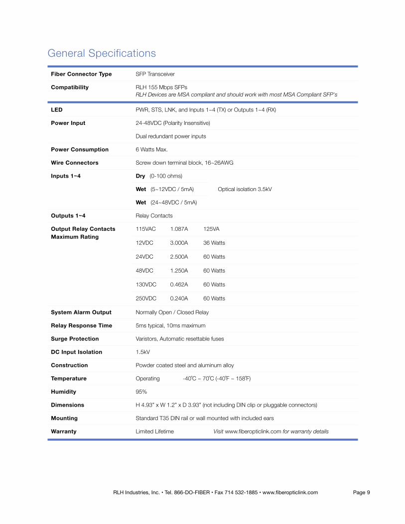
General Specifications Fiber Connector Type SFP Transceiver
Compatibility RLH 155 Mbps SFPsRLH Devices are MSA compliant and should work with most MSA Compliant SFP's
LED PWR, STS, LNK, and Inputs 1~4 (TX) or Outputs 1~4 (RX)
Power Input 24-48VDC (Polarity Insensitive)
Dual redundant power inputs
Power Consumption 6 Watts Max.
Wire Connectors Screw down terminal block, 16~26AWG
Inputs 1~4 Dry (0-100 ohms)
Optical isolation 3.5kV Wet (5~12VDC / 5mA)
Wet (24~48VDC / 5mA)
Outputs 1~4 Relay Contacts
Output Relay Contacts Maximum Rating
115VAC 1.087A 125VA
12VDC 3.000A 36 Watts
24VDC 2.500A 60 Watts
48VDC 1.250A 60 Watts
130VDC 0.462A 60 Watts
250VDC 0.240A 60 Watts
System Alarm Output Normally Open / Closed Relay
Relay Response Time 5ms typical, 10ms maximum
Surge Protection Varistors, Automatic resettable fuses
DC Input Isolation 1.5kV
Construction Powder coated steel and aluminum alloy
Temperature Operating -40˚C ~ 70˚C (-40˚F ~ 158˚F)
Humidity 95%
Dimensions H 4.93” x W 1.2” x D 3.93” (not including DIN clip or pluggable connectors)
Mounting Standard T35 DIN rail or wall mounted with included ears
Warranty Limited Lifetime Visit www.fiberopticlink.com for warranty details
RLH Industries, Inc. • Tel. 866-DO-FIBER • Fax 714 532-1885 • www.fiberopticlink.com Page �9

Technical Support
Contact Information
!
Normal technical support: (Mon - Fri 6am - 6pm PST)
(714) 532-1672 Toll Free 1-800-877-1672 Toll Free 1-866-DO-FIBER
Email: [email protected]/7 technical support:(Outside normal business hours)
Toll Free 1-855-RLH-24X7 Toll Free 1-855-754-2497
Corporate Headquarters: RLH Industries, Inc. 936 N. Main Street Orange, CA 92867 USA
Phone: (714) 532-1672 Toll Free 1-800-877-1672 Toll Free 1-866-DO-FIBER
Fax: (714) 532-1885Email: [email protected] site: www.fiberopticlink.com
RLH Industries, Inc. 936 N. Main Street, Orange, CA 92867 USA T: (714) 532-1672 F: (714) 532-1885
Please contact your RLH sales representative for pricing and delivery information.
Specifications subject to change without notice.
Page � RLH Industries, Inc. • Tel. 866-DO-FIBER • Fax 714 532-1885 • www.fiberopticlink.com10