Embed Size (px)
Citation preview

/ 1ADJ
(/3V
Technical Memorandum 25-77 A
DEVELOPMENT OF ADVANCED CONCEPTS FOR NOISE REDUCTION
N TRACKED VEHICLES
Thomas R. Nor. sAnthony G. Galaitses
Bolt, Beranek, and Newman, Inc.
Ronald B. HareFMC Corporation
Georges R. Garinther
OT 26 1911August 1977
AMCMS Code 672716.11 .H70C0 ,-
C-,
)L .Approved for public rclase; N
6 A m distribution unlimited. I
U. S. ARMY HUMAN ENGINEERING LABORATORY
Aberdeen Proving Ground, Maryland

Destroy this report when no longer needed.Do not return it to the originator.
The findings in this report are not to be construed as an official Departmentof the Army position unless so designated by other authorized documents.Use of trade namets in this report does not constitute an official endorsementor approval of the use of such commercial produc~s.
Useoftrdenams n hi reor desno Cositt anofca nosmn
Unclassif iedSECURITY CLASSIFICATION OF THIS PAGE (Wheon Data Filtered)
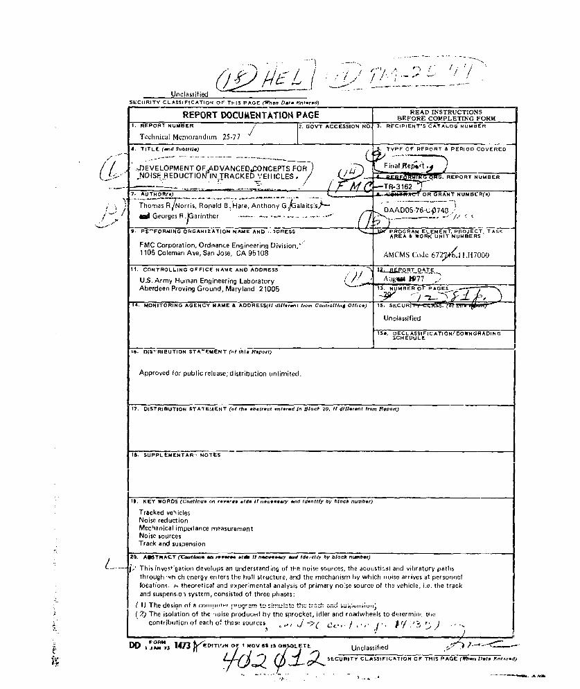
READ INSTRUCTIONSREPORT DOCUMENTATION PAGE BEFORE COMPLETINGFORM
Aerdecl e.novnrund, Marlad7 200
A. TITORIN ( GENC SuAttle TYP OFRSSI REPORTen Isou PERIODl~t COVEREID S
7. AUTHOR(&)IO STATEMENTN (o Kit *berec KNle~ Tn N~cP U0 Mf Bflt fCo Repo
Il eore O R .(Co inter .. e i.I eeer n dniyb lc ubr
FMChCrain mpdnance Easureen iiso,
.S. ATrmyT Humn. Engieerieg Labor ~ato Aagd 05.ih y lckn7
AbeThisn Prating devropsd anrtand 100 nf. th os oreteasIcaNd irtr ah
ApproThed d fson ofli relese dsr iuton u~im ited.t~~ ci~
17. ~ ~ ~ LL~', DITIBTO CLTATEIMENTO OFf THIS abAGEc (Wfren inl HRnI20.t tf fodRpot
IS SUPEMNA -N .0

SECURITY CLASSIFICATION OF THIS PAGE(Whli D.f. 9I.-d)-%
- 13) The measurement of vibration levels at the suspension system, and force-to-ioise transfer functionsfor predicting interior noise levels.
This study indicates that at speeds above 10 mpil the engine is not a major contributor to noise, and theroadwheels produce significantly less noise Loan the sprocket and idler. The study results indicate thatthe greatest potential for noise reduction has in providing a softer compliance between the idler arid thetrack. This should be followed !y lowering the stiffness of the sprocket and finally ay controllingroadwheel noise. The idler stiffness can be lowered either at the hub or at the rim, however rimcompliance poses fewer design problems
.
Z
,. -~\ \
Unclassified
SECURITY CLASSIFICATION OF THIS PAGE(Iflten Dloe Ent-e)

AMCMS Code 672716.11I.H7000 Technical Memorandum 25-77
DEVELOPMENT OF ADVANCED CONCEPTS FOR NOISE REDUCTION
IN TRACKED VEHICLES
Thomas R. NorrisAnthony G. Galaitsis
Bolt, Beranek, and Newman, Inc.
Ronald B. HareFMC Corporation
Georges R. Garinther
August 1977
APPROVED.:JOHN D, WEISZDirectorU. S. Army Human Engineering Laboratory
U. S. ARMY HUMAN ENGINEERING LABORATORYAberdeen Proving Ground, Maryland 21005
Approved for public releaSe;
distribution unlimited.

TABLE OF CONTENTS
Page
INTRODUCTION ........................................................ 3O bjectives aiid G oals ....... ....... ........................................ 3General Dis.ussion of Tracked Vehicla Interio Noise ............................. 3Technical ApproacL . ............................ ......................... 7Sum mary of Results and Conclusions ............................................ 7
EVALUATION OF NOISE SOURCE CONTRIBUTIONS ............................. 14T est V ehicle ............................................................. . . 14Data Acquisition for Suspension Noise and Vibration .............................. 15D ata P resentation ............................................................ 17Noise Characteristics of Production M 113A1 ..................................... 18Idler N oise Contribution ....................................................... 19Sprocket Noise Contribution ................................................... 23Roadwheel Noise Contribution ................................................. 25Analysis of High Speed M ovies ................................................. 30
IMIFEDANCE AND TRANSFER FUNCTION MEASUREMENTS ...................... 32Purpose of Hull M easurem ents ................................................. 32Measurements of Impedances and Transfer Functions ............................. 32Results of Impedance and Transfer Function Measurements ...................... 34
NOISE REDUCTION ESTIMATES OF COMPLIANT IDLER RIMS AND HUBS .......... 39Background ...................................... 39Estimation of Noise Reductions .............................................. 40Conclusions Based on Noise Reduction Estimates ................................ 44
APPENDIX A LIST OF INSTRUMENTATION AND DA?4L DEVELOPED ............. 45APPENDIX B ANALYSIS OF ISOLATION EFFECTVENESR7S OF COMPLIATT
RIMS AND HUBS ........................ ................. 49APPENDIX C TRACK SHOE IMPACT NOISE ANALYSIS ......................... 53
LIST OF ILLUSTRAT..... 4S
Figure Page
1 Sources and Paths Responsible for Interior Noise in Tracked Vehicles ............... 42 Chordal Action ....................................................... 63 Speed Dependence of Track System Noise Sources at Crew Position ................. 84 Crew Area Track System No'se Sources Compared at Various Speeds ............... t5 Noise Source Spe :tra at 15 MPH at Center of Crew Compartment ................... 106 Noise Source Spectra at 25 MPH at Center of Crew Compartment ................... 117 Noise Source Spectra at 32 MPH at Center of Crew Compartment ................... 118 Noise Source Spf ctra at 15 MPH at Driver's PositioA .............................. 129 Noi-e Source Sp 3ctra at 25 MPH at Driver's Position ............................. 12
10 Noise Source Spectra at 32 MPH at Driver's Position .............................. 13
LIST OF ILLUSTRATIONS (Cortinued)
Figure Page
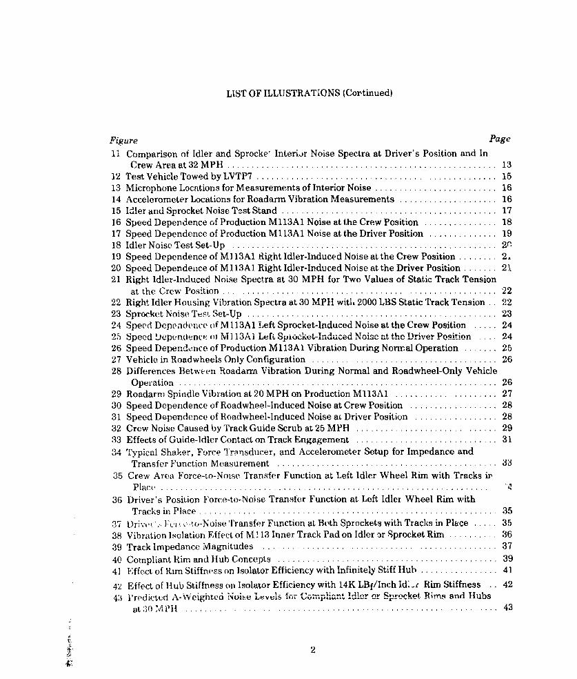
11 Comparison of Idler and Sprocket Interior Noise Spectra at Driver's Position and InCrew A rea at 32 M PH .................................................... . 13
12 Test Vehicle Towed by LVTP7 ................................................. 1513 Microphone Locations for Measurements of Interior Noise ......................... 1614 Accelerometer Locations for Roadarin Vibration Measurements .................... 1615 ILler and Sprocket Noise Test Stand ....................................... .... 1716 Speed Dependence of Production M113A1 Noise at the Crew Position ............... 1817 Speed Dependence of Production M113A1 Noise at the Driver Position .............. 1918 Idler N oise T est Set-U p ........ ...... ............................ ......... 2a19 Speed Dependence of M) 13A1 Right Idler-Induced Noise at the Crew Position .2...... 220 Speed Dependeuce of MI13A1 Right Idler-Induced Noise at the Driver Position ....... 2121 Right Idler-Induced Noise Spectra at 30 MPH for Two Values of Static Track Tension
at the Crew Position ............. ....................... 2222 Right Idler Housing Vibration Spectra at 30 MPH with 2000 LBS Static Track Tension.. 2223 Sprocket Noise Test Set-Up .............. .......................... . 2324 Speed Dependeuce of M 113A1 Left Sprocket-Induced Noise at the Crew Position ..... 2425 Speed Depencience of Mi i3Al .Le .. Spiocket-nducedA Nois at the Driver Position 24
26 Speed Dependence of Production M 113A 1 Vibration During Normal Operation ....... 2527 Vehicle in Roadwheels Only Configuration ...................................... 2628 Differences Between Roadarrm Vibration During Normal and Roadwheel-Only Vehicle
O p e ra tio n ........ .......... ... .. . .................................. .. 2 629 Roadarm Spinidle Vibration at 20 MPH on Production M13A1 ..................... 2730 Speed Dependence of Roadwheel-Induced Noise at Crew Position .................. 2831 Speed Dependence of Roadwheel-Induced Noise ac Driver Position ................. 28
32 Crew Noise Caused by Track Guide Scrub at 25 MPH ............................ 2933 Effects of Guide-Idler Contact on Track Engagement ............................. 31
34 Typical Shaker, Force Transducer, and Accelerometer Setup for Impedance andTransfer Function M easurem ent ............................................. 33
35 Crew Area Force-to-Noise Transfer Function at Left Idler Wheel Rim with Tracks i,P la c e ........... .......... ............................. .......
36 Driver's Position Force-to-Noise Transfer Function at Left Idler Wheel Rim withT racks in P lace ....................................... .......... 35
37 Drive ",. F.i (,-to-Noise Transfer Function at Both Sprockets with Tracks in Place ... 3538 Vibration Isolation Effect of M1 13 Inner Track Pad on Idler or Sprocket Rim .......... 3639 Track Impedance Magnitudes ................................... ......... 37
40 Com pliant Rim and Hub Concepts ............................................. 39
41 Effect of Rim Stiffness on Isolator Efficiency with Infinitely Stiff Hub ................ 41
42 Effect of Hub Stiffness on Isolator Efficiency with 14K LBf/Inch Id-.r Rim Stiffness . . 42
43 Plredicted A-Weighted Noise Lt vls foi- Co-upliant dIer or Sprrcket Rim, and Hubsat 30 ............... .. ...... ............ .. ........ ....... ......... 43
2

INTRODUCTION
OBJECTIVES AND GOALS
The basic objective of this program was to develop vehicle interior noise reduction conceptsthat will result in light-weight tracked vehicles quiet enough so that crew members will not berequired to use heaiing protecters in addition to the DH132 Combat Vehicle Crewmen's Hel-met.
Accordingly, the interior noise goal has been set at 100 dB(A) in conformance with theguidelines of MIL-STD-1474, Category B. Achievement of this goal requires a 15 dB(A) noisereduction, primarily at low frequencies. In a weight-critical machine designed for survivabilityin extrame environments, this represents a major technical challenge.
The U. S. Army Human Engineering Laboratory has recognized that practical design modi-fications required to achieve significant interior noise reductions do not exist at present, andthat their development must be based on experimental and analytical evaluations of the noisesources and their transmission paths. Previous studies (e.g., References 2, 7, 12 and 13) haveidentified the major noise sources but have not quantified their contributions. An extensivereview of available literatue on the subject has yielded no general design guidance for noisereduction in tracked vehicles.
The specific objective of this investigation was to develop track sy-.tem noise reduction con-cepts based upon a thorougih understanding of tracked vehicle noise sources and transmissionpaths. The goals of this program may be stated as follows:
* to quantify the noise contributions of the idlers, sprockets and roadwhee1iv
* to establish the potential roise reductions that might be obtained by suspension componentmodificatlon
" to deveiop a digital computer program for use in conjunction with force-noise transfer func-tion measurements in the evaluation of track noise source reducing concepts.
The Ml13A1 vehicle was chosen for this study because of its availability and relatively lowcost ot replacement parts for experimental modification. The Ml13A1 design is typical oflightweight high speed vehicles. Concepts based on M113A1 requirements are there-fore readily adapted to other tracked vehicles in its class.
Noise sources other than the idlers, sprockets and roadwheels will be considered in futureprograms since suspension noise sources dominate at present.
GENERAL DISCUSSION OF TRACKED VEHICLE INTERIOR NOISE
Interior noise in tracked vehicles results from track interaction with the drive sprockets,idler wheels, and roadwheels. The engine and powertrain is a secondary noise cource in mosttracked vehicles. Some vehicles, such as the M69 and MICV, have track support rollers whichmay , l,,G prmuvI1c i1uerior noise. F igure I is a schematic representation of trackedvehicle noise sources and vibration paths.
3

Noise in moving tracked vehicles results from vibration of the hull which is excited by sus-pension and engine-powertrain components. The hull structure distributes vibration energyfrom each source to the remainder of the hull which, in turn, radiates noise. The interior noiselevels at thie driver and crew locations are established by the direct radiation of sound from thehull surfaces and by reverberant buildup.
Accordingly, noise control in lightweight tracked vehicles is more a matter of reducing hullvibration than installing ba-'riers or absorbers. Consideration of "conventional" acousticnoise control barriers and absorbers showed that, because the entire hull radiates noise, the100 dB(A) noise goal could not be met within practical weight, cost, durability and size limits.Therefore, the noise control concepts addressed in this study wore: (1) the reduction of vibra-tion at the various sources, and (2) attenuation of vibration energy paths between sources andthe huil.
LU
NOISE NOISE REVERBERANT DRIVER ANDENGINE AND DRIVE TRAIN CR
BUU LOCATIONS
CO
I NOISE
VIBRATION VIBRATION
Elii.VEHICLE HULL STRUCTURE i
VIBRATION VIBRATION t VIBRATION VIBRATION
ROADARMS
0 0 ©0SPROCKET IDLER ROADWHEELS SUPPORT ROLLERS
Figure 1. Schematic Diagram of Sources and Paths Responsible for Interior Noisein Tracked Vehicles
4

Only the major M 113 suspension noise sources were examined in this study. Previousstudies (Reference 7) have shown thut other noise sources are secondary; such as the engine,powertrain, and final drive gearing. Fuither, suspension sources are specific tracked vehiclenoise problems and the technology needed to successfully reduce the noise from these sourcesdoes not exist at present.
The basic phenomena responsible for tracked vehicle hull vibration at typical operatingspeeds are tension changes due to the geometry of track engagement with the idler andsprocket wheels, and forces resulting from impacts between track shoes and the idler andsprocket wheels. Both of these phenomena occur at track-laying rate.
Chordal action occurs as follows. As the track is carried around a wheel, it cannot form asmooth arc (as could a belt) because of the rigid track shoes. Instead, the shoes form part of apolygon, which is equivaleni to a series of chords of a circle; hence the synonyms "chordalaction" or "polygonal action".
Chordal action causes the velocities and accelerations of entering and exiting track pins tovary in a cyclical manner. In Figure 2a, as a track pin arrives directly above the wheel, itshorizontal velocity is at a maximun and its vertical (radial) velocity is zero. One-half pitchcycle later (Figure 2b), the situation is changed. At this point, horizontal velocity is reduced,while vertical downward velocity is increased. (For a 10-tooth M113 sprocket, this downwardvelocity is about 10% of the vehicle's forward speed.) Because of the rapidity of the velocitychange and the massiveness of the track, considerable force is required to impose the neces-sary accelerations on entering (or exiting) track shoes. These imposed forces result in consid-erable reaction forces which, in turn, vibrate the hull.
The second major source cf hull vibration is the impact which results from chordal action.Impacts occur only at the entering track shoe. As shown in Figure 2, the downward velocity ofthe entering track strand is suddenly interrupted by the idler wheel. The net result is a verypowerful impact against the wheel causing the entire hull to vibrate. At present, data are notavailable that can be used to clearly separate impact noise from the noise generated by tracktension changes. Also, the impacts and chordal action both cause the entire track to vibrate,so that all track shoes in contact with the wheel exert vibration forces.
Figure 2 represents the quasi-static case; i.e., the motion shown would correspond only to anear-zero vehicle speed. For track systems operating at high speed, track inertia may causethe impacts either to increase or to disappear and could cause the track shoes to slide or rockon the wheel. Centrifugal force, variable tension of both track strands, and rubber cushioningeffvieLs vi combine to greatly modify chordal action and impact forces.
Further discussion of chordal acticn is available in the literature. Unfortunately, availableworks describe only power transmission chains and their dynamics. Such chai-is are compara-tively light in weight for the power that they transmit; so the discussions do ntt dire,.tly applyto relatively heavy vehicle tracks.
5

ASA TRACK PIN ARRIVES DIRECTLY ALOVE 1HEWHEEL,
ITS HORIZONTAL VELOCITY IS AT A MAXIMUM AND ITS
VERTICAL (RADIAL) VELOCITY IS ZERO,
V P 0
00
0 a. Prior to Impact
ONE-HALF PITCH CYCLE LATER, THE SITUATION HAS
CHANGED. AT THIS POINT, HORIZONTAL VELOCITYIS REDUCED WHILE VERTICAL VELOCITY HAS
INCREASED-THE ACCELERATIONS IN BOTH DIRECTIONSCAUSE LARGE VIBRAI ION FORCES TO BE EXERTED ON THE~WHEEL.
V P
0A SHARP IMPACT IS ABOUT TO OCCUR.
b. At Impact
Figure 2. Chordal Action
6
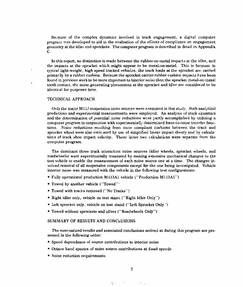
Be.-ause of the complex dynamics involved in track engagement, a digital computerprogran was developed to aid in the evaluation of the effects of compliance on engagementgeometry at the idlei and sprockets. The computer program is described in detail in AppendixC.
In this report, no distinction is made between the rubber-on-metal impacts at the idler, andthe impacts at the sprocket which might appear to be metal-on-metal. This is because intypical light-weight, high speed tracked vehicles, the track loads at the sprocket are carried
primarily by a rubber cushion. Because the sprocket carrier rubber cushion impacts bave beenfound in previous work to be more important to interior noise than the sprocket metal-on-metaltooth contact, the noise generating phenomena at the sprocket and idler are considered to beidentical for purposes here.
TECHNICAL, APPROACH
Only the major M 113 suspension noise sources were examined in this study. Both analjticalpredictions and experim-ntal measurements were employed. An analysis of track dynamicsand the determination of potential noise reductions were partly accomplished by utilizLng acomputer program in conjur.ction with experimentally determined force-to-noise transfer func-tions. Noise reductions reulting from mere compliant cushions between the track andsprocket wheel were also estin.ated by use of simplified linear impact theory and by calcula-tions of track shoe impact velocity. These lakter two calculations were separate from thecomputer program.
The dominant three track interaction noise sources (idler wheels, sprocket wheels, androadwheels) were experimentally measured by making extensive mechanical changes to thetest vehicle to enable the measurement of each noise source one at a time. The changes in-volved removal of all suspension components except for the one being investigated. Vehicleinterior noise was measured with the vehicle in the following test configurations:
* Fully operational production MI13A1 vehicle ("Production MI13AI")
* Towed by another vehicle ("Towed."
• Towed with tracks removed ("No Tracks")
* Right idler only, vehicle on test stanri ("Right Idler Only")
* Left sprocket only, vehicle on test stand ("Left Sprocket Only ')
0 Towed without sprockets and idiers ("Roadwheels Only")
SUMMARY OF RESULTS AND CONCLUSIONS
The summarized results and associated conclusions arrived at during this program are pre-sented in the following order:
* Speed dependence of source contributions to interior noise
• Octave band spectra of noise source contributions at fixed speeds
" Noise reduction requirements
7

Speed Dependence of Noise Source Contributions to Interior Noise
Figure j summarizes the A-weighted noise levels at the crew microphone position producedby the right idler, left sprocket: and all ten roadwheels as track speed was varied. ProductionM) 13A1 self-powered end also towed measurements ere shown, The 100 dB(A) noise goal isshown as a dashed horizontal line. Idler-dependent and sprocket-dependent noise (i.e., bothright and left) should yield levels that are 3 dB higher.
fl 1~ m 1T r i I II IT- I
__________E~)CO M113A I, _________ PRODUCTION MIMAI.ii TOWED SELF POWERED
la
> ............ LEFT SPROCKET ONLY
700R NUliS GOAL
LU
1015 20 25TRACK SP EED (MI] ES PER HO UR)
F'.-i Speed Dependence of Track System Noise Sources at Crew Position
IFIiur A qh ws th. P same data at 15, 20, 295, and 30 miles per hour and more cleao, Showsthe contributions of idlers, sprockets, and roadwheels to overall interior noise of the MJ.13A1vehicle.
8

120NOTE: IDLER AND SPROCKET LEVELS ARE
-MEASURED VALUES PLUS 3dB TO
a. 115 __ ACCOUNT FORB OTH RIGHT AND EXTRAPOLATED.4LEFT SIDES _-IVALUEE i
3 110 -- --I ILUJ
LLu
105
_J C 1. 100 dB(A)C) 2' 0-IoI NOISE GOAL;~~~U Ilui z ,1I..95 := I _ _I_"_-
0 cr ~ ~ 0 L
. 90 0"O0=" I _ _
15 MPH 20 MPH 25 MPH' 30 MPH
Figure 4, Crew Area Track System Noise Sources Compared at Various Speeds
Analysis ot Figures 3 and 4 yields the following conclusions about track system noise sources:
* Significant reduction of any single suspensi n noise source will result in a relatively smalloverall noise reduction, especially at spee"' above 25 miles per hour.
* Overa~ll vehicl, noise is domiatd by the id.klrs at all measured vehicle speeds, especially atspeeds below 20 miles per hour.
*At speeds above 20 miles per hour, the sprockets approach the idler in their contribution tooverall noise.
* Straight-line extrapolation of the roadwheel noise level trend indicates that roadwheels maybe significant contributors to overall noise at speeds of 30 miles per hour and above.
* Roadwheel dependent noise is significantly reduced when the tracks are removed, indicat-ing that the interaction of the rough inner track surface and roadwheels is responsible forthe majority of the vibration excitation and resulting interior noise.
Other conclusions resulting from this program are:
* The leading roadwhee] produces more hull vibration and noise than any other roadwheel.However, to achieve significant roadwheel noise reduction, the noise from all roadwheelsmust be reduced.
• The engine is not an important contributor to interior noise above vehicle speeds of about 10 °
miles pet hour (References 7 and 14k.• Idler, sprocket, and roadwheel noise reductions of 15 to 20 dB(A) are required for the 100
db(A) noise goal to be achieved at the 30 miles per hour vehicle speed.
•During normal operation, the driver position averages 1-4 dB(A) more noise than does the IVe pio
9

* A softer cushion between the track and idler or sprocket rim offers the most potential noisereduction with a reasonable practicality risk.
* Horizontal and vertical force reactions at the idler and sprocket mounts produce approxi-mately the same interior noise level in the 250 Hz octave band.
* Both horizontal and vertical forces exerted on the idler and sprocket must be controlled toachieve appreciable noise reduction.
* For idler and sprocket noise control, hub compliance is potentially more effective than rimcompliance; but it poses serious design problems.
" Most or all of the required noise reduction for the idler and sprocket appears to beachievable with practical rim compliance concepts.
* If practical, reduction of the hull vibration force-to-noise transfer efficiency would provide auseful additional noise reduction.
* Selection of the vehicle operating speed for determination of vehicle interior noise perfor-mance is critical, owing to the presence of vibration response peaks within the normal speedrange of the vehicle. Such peaks can reduce the repeatability of noise measurements.
* A track tension reduction from 3000 to 2000 pounds lowers interior noise by less than 2 dB.Practical track tension reductions, therefore, will not result in significant noise reduction.
Figures 5, 6, and 7 show the octave band spectrm of the various noise sources in the crewarea at vehicle speeds of 15, 25,, anA 3 miles per hoar along with the 100 dB(A) noise goalspectrum given by MIL-STD-1474, Category B. Engiri, only noise levels (Reference 14) areshown for comparison purposes.
12 L~ 24 PROIDUCTION M113A1 +__ 7,___ . -_RIGHT IDLER ONLY
/~ LEFT SPROCKETO0NLY
S- "-MIL-STO-1474co "(CATEGORY B)
WE1'' O EEL NL " - '- -' %° -
90 -_ -4NIEdY(70P) ,m . 1-1 _ "_ -".. 4. _ _J
C
a-.Z
C4
go - 0W ENGI ONLY (170 PM
31.5 63 125 250 500 1000 2000 4000 8000 16000
UbGvND M-'u 15.n"nln tuUt -nrTc
Figure 5. Noise Source Spectra at 15 MPH at Center of Crew Compartnent
10

PRODUCTION M113A I
120 RIGHT IDLER ONLY -
a.. - LEFT SPROCKET ONLY
---a -- - - -
1?10a _
- 10 ROAOWHEELS ONLY
31~ 63 125 250 5o0 10)00 2000 4000 8000 100
OCTAVE UAND CENTER FREQdENCY -HERTZ
Figure 6. Noise Source Spectra at 2,5 MPH at Center df Crew Compartment
PRODUCTION Ml 13A I
713A I -
oU 0
ENUN ONLY (2600KE RPMNLY__
OCTA ~ ~ ~ ~ ~ (ATG-9 BADCNERFEUNC ET
Fiue7 os uc petaa 2 M Ha4ete fCe o prm n
LAii

Figures 8, 9, and 10 show results similar to the above figures at the driver's microphoneposition.
-7 ROUCTION M113AI
S 120- _,.-RIGHT IDLER ONLY> 4LFSPR0CKETO0N LY
-J *.--- MIL-TD-1474(CATEGORY 0)
cc_ _ _ _ 7 -_ _ _ _ _ _
CM
fz
o 90 ROADWHEELS ONLY -__ ___
31.5 63 1?.xi 250 500 1000 2000 4000 80-00 16000
OCTAVE BAND CENTER FRECUUENCY -H4ERTZ
Figure 8. Noise Source sipectra at 15 MPH at Driver's Position
-PRODUCTION M113AI
-L4=. *4 LEFTSPROCKET ONLY
MIL-STD-1474(CATEGORY B)
''k
> ~ ~ ~ - ROADWHEELS ONLY-1" ----- &
31.5 63 125 250 500 1000 2000 4000 8000 16000
U.,W LtIVIDCENTE FREUULNCY -HERTZ
Figure 9. Noise Source Spectra at 25 MPH at Driver's Position
12

SPROUCTION M M13A
1 2 1. -- - ; - - H T ID L E R O N L Y
'I-. \ .. /- '% / -LEFT SPROCKET ONLY
LU .. ...I L-STO-1474!CATEGORY B
oM
LW,, 11o0- ' ' " - /..
" 3 100(C
90
31.5 63 125 250 500 loco 2000 4000 NOR 15000
NOTE: ROADWHEELS -ONLY MEASLiRMENTS COULD NOT BE MADE AT 32 MPH
OCTAVE BAND CENTER FREQUENCY - HERTZ
Figure 10. Noise Source Spectra at 32 MPH at Driver's Position
Figure 11 compares noise levels at the driver and crew microphone positicas due to one
sprocket or idler at 32 MPH.
DRIVER'S POSITION - LEFT SPROCKET ONLY
- .DRIVER'S POSITION-RIGHT IDLER ONLY _
> CREW NOISE -RIGHT ID2 LER ON LY±
-'_ -- C-----rCREW NOISE - LEFT SPROCKET ON LY
120 - - -
> _
110 - " *"*-_: "2 -
0 00V t _- --- 0 N-o, 100 ____ ___ -- _
31.5 63 125 250 500 1000 2000 4000 8000 16000
OCTAVF AND CENTER FREQUENCY, (Hz)
Figure 11. Comparison of Idler and Sprocket Interior Noise Spectra at Driver's Position andin Crew Area at 32 MPH
13
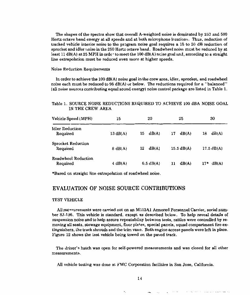
The shapes of the spectra show that overall A-weighted noise is dominated by 250 and 500Hertz octave band energy at all speeds and at both microphone lccation, . Thus, reduction oftracked vehicle interior noise to the prigram noise goal requires a 15 to 20 dB reduction ofsprocket and idler noise in the 250 Hertz octave band. Roadwheel noisc must be reduced by atleast 11 dB(A) at, 25 MPH in orde - to meet the 100 dB(A) ncise goal and, according to a straightline extrapolation must be reduced even more at higher speeds.
Noise Reduction Requirements
In order to achieve the 100 dB(A) noise goal in the crew area, idler, sprocket, and roadwheelnoise each must be reduced to 95 dB(A) or below. The reductions required for a "balanced"(alh noise sources contributing equal sound energy) noise control package are listed in Table 1.
Table 1. SOURCE NOISE REDUCTIONS REQUIRED TO ACHIEVE 100 dBA NOISE GOAL
IN THE CREW AREA
Vehicle Speed (MPH) 15 20 25 30
Idler ReductionRequired 13 dB(A) 15 dBIA) 17 dB(A) 18 dB(A)
Sprocket ReductionRequired 8 dB(A) 12 dB(A) 15.5 dB(A) 17.5 dB(A)
Roadwheel ReductionRequired 4 dB(A) 6.5 dB(A) 11 dB(A) 17* dB(A)
*Based on straight line extrapolation of roadwheel noise.
EVALUATION OF NOISE SOURCE CONTRIBUTIONS
TEST VEHICLE
All me-ourenients were carried out on an Ml13A1 Armored Personnel Carrier, serial num-ber SJ-136. This vehicle is standard, except as described below. To help reveal details ofsuspension noise and to help assure repeatability between tests, rattles were controlled by re-moving all seats, stowage equipment, floor pletes, special panels, squad compartment fire ex-tinguishers, the track shrouds and the trim vane. Both engine access panels were left in place.Figure 12 shows the test vehicle being towed on the paved track.
The driver's hatch was open for self-powered measurements and was closed for all othermeasurements.
All vehicle testing was done at FMC Corporation facilities in San Jose, California.
14

Figure 12. Test Vehicle Towed by LVTP7
DATA ACQUISITION FOR SUSPENSION NOISE AND VIBRATION
Vehicle interior noise measurements were made by means of two microphones; one locatedjust behind the driver's head position, and the other in the crew compartment. The driver'sposition microphone was located 8-1/2 inches from the left upper eide plate, 8-1/2 inchesbelow the ceiling, and 1/2 inch aft of the rear engine access panel surface. During measure-ments, the crew compartment microphone was mechanically rotated in a horizontal 6-inchdiameter circle about a point located 38 inches from the righL upper side plate, 7 inches belowthe ceiling, and 44 inches aft of the rear engine panel. Rottion of the crew position micro-phone was employed in order to obtain a spatial averaging of the measured sound, and thusobtain a more representative sample.
15

The sound level meter and microphone used provided an "unweighted" (also sometimescalled flat, over-all, linear, or ali-pass) frequency pass band extending fromn 20 to 16,000 Hz.Figure 13 shows the microphones positioned in the test vehicle.
_____ CREW POSIE NIORIVER POSITION MCROPHONE
Figure 13. Microphone Locations for Measurements of.Interior Noise
Two accelerometers were mounted to each of Roaddrms #1, #3, and #5. As shown in Figur-e14, one accelerometer measured acceleration parallel to the roadarin axis, and the othermeasured accelerations perpe~ndicular to the same axis.
_ .rRLLELACCELE0METER
Figure 14. Accelerometer Locations for Roadarm Vibration Measurements.
16

Running tests were conducted on FMC's paved track facility. Idler and sprocket tests werecarried out with the vehicle mounted on the test stand show~n in Figure 15.
Noise, vehicie speed, and vibratic - data were recorded on magnetic tape (four channels at atime) during gradual vehicle accelerations and decelerations. This test method was chosenover the plamed series of fixed speeds because the vehicle drivers had difficulty inestablishin~g accurate steady-state vehicle speeds, and also the continuous speed versus kloisesweeps resulted in especially informative graphs.
High speed (2,000 frames per second) movies were taken of idler and sprocket engagementon the test stand at various vehicle speeds and track tensions. Th3se films were used for avisual examination of track strand motion, engagement and disengagement geometries, wavemotion, and impact characteristics.
DATA PRESENTATION
Most of the noise data in this report are presented as graphs of sound pressure level versusspeed. This method yields information that is not readily apparent from steady-state spectraldata. Slopes and cyclic variations of noise with speed, which are clearly shown on thesegraphs, have yielded valuable clues to the noise performance of the sprockets, idlers, androadwhet -s.
Illiil111111--
1
Figure 15. Idler and Sprocket Noise Test Stand
These curves are supplemented by octave band spectra corresponding to an .verage vehiclespeed established during the gradual vehicle accelerations and decelerations. One-third..... band anal.ys.. s WaS Pe med, but large momentary variations in the low frequencybands yielded results inconsistent with octave band and A-weighted data.
17 jI

Although test stand measurements were made at track speeds up to about 42 mph, towingoperations were limited to speeds below 30 mph owing to safety restrictions. The datapresentations for all tests are thus limited to approximately 30 mph. Since this speed rangevJso represents the major portion of tracked vehicle operating time, the data presented is re-presentative. The 30 to 42 mph speed range on the test stand resulted in a 1 to 2 dB(A)increase in both idler and sprocket noise and showed no other significant trends.
The A-weighted and octave band sound leve! data are estimated to be accurate to within - 2dB, and the vehicle speed date are typically accurate to within + 1 mph.
NOISE CHARACTERISTICS OF PRODUCTION M113A1
Figures 16 and 17 show the speed-dependence of the unweighted octave band, and A-weighted noise levels at the crew and driver microphone positions of the production M 113A1operating on the paved track.
140
OCTAVE BAND
0 LEVELS
LIN I jHE 50 Hz
120 125z H7
1000H
-%- q00 Hz
a1000H
100 15 H025z
VEHICLE SPEED (MILES PER HOUR)
Figure 16. Speed Dependence of Production M113A1 Noise at the Crew Position
Tili octave band curves are more or less parallel to each other which indicates that thespectrum !bI ape changeb little with speed. The curves also show that the increase in vehiclespeed from 20 to 30 miles per hour produced only a 2 dB(A) increase in the noise level. Also,noise at the driver's position averages 2 dB(A) higher than at the crew position.
18

Noise and vibration measurements of the untmodified MI113A1 were made several timesthroughout the program. Four separate crew noise runs yielded unweighted noise versusspeed curves which were within + 2 dB of et.ch P t n- Deeds, A maximum deviation of6 dI3 occurred in the unweighted noise Jei< .*j-ds near 28 miles per hour.
At 28 miles per hour, a speed deviation vf oi~y 1. Xfl pe- hour could vary the noise level byup to 6 dB, as shown on Figures 16 and 17. TIAs resu,4 erLphadLzes the importance of checkingncise measurements at various trackeA v, .,le ., ̂ ce, s. 0,nfcificatior conformance noise testsfor th-- M113AI are presently run at a rniui vehicko epeel" of 28 miles per hour which,unfortunately, coincides with the least '.ptlepo. nt mi the 11113 z-pecd range.
FTTr-1I!IFT11140
130
:Or
12 120
110
0
1000H
IDLERd(A NOISE COTRBUIO
90 19

Noise measurements gere made at static track tensic,o of 2000 and 3000 pounds. Tensionwas determined on tb: basis of static catenary sag measurements of the upper track strandbetween the idler and sprocket.*
VARIABLE-SPEED ELECTRIC DRIVE
NORMALLY MOUNTEDIDLER ASSEMBLY
SPROCK ET ___
ASSEMBLYMOUNTED ON
TEST STAND
NO CONTACTWi (H VEHICLEHULL ,
1
LEFT SIDE TRACK N 3T MOVIN-'
Figure 18. Idler Noise Test Set-Up
Figures 19 and 20 show the speed dependence up to 31 mph of idler-only noise at the crewand driver microphone positions. Measurements were also made at vehicle speeds up to 40mph which show the same spectLrum shape but increased sieaduily by i - 3 dB ovez- the 31 ,,phllevels. The essential parallelism of these speed dependence curves in the octave bands above125 Hz indicates that the spectrum shape changes little with speed.
Comparison of Figures 19 and 20 shows that the right idler-induced driver's position noiselevels are 1 to 2 dBA) higher than crew area noise levels.
The effect of track tension on right idler-induced noise is evidenL fmm Figure 21, whichshows idler noise one-third octave band spectra for static track tensions of 2000 and 3000pounds. The 1000 pound increase in tension resulted in a 2 dB increase for most one-thirdoctave bands and for the A.-weighted sound level. The noise increase was similar at thedriver's position and crew area. Because of this small dependence of noise on track tension,practical track *Jn ;)n reductions will not produce significant noise reductions (also see Re-ferences 12 and 13 for similar results).
One-third octave band spectra of horizontal and vertical vibration measured on the rightidler housing are presented in Figure 22. The horizontal vibration levels exceed the verticallevels by about 3 dB at the "frequency bands of primary concern" (125 to 500 Hz); that is,those frequencies requiring the most noise reduction.
*The static tension T(lb) is given by the common t atenary equation T = W(4S 2 + L2 )/8Swhere: W is the weight of track per unit length (3.5 lb/in.),
L is the length of unsupported track strand 1150 in.). andS is the measured static sag in inches
20

120 _____(N
25 H
ZC 110:A WEWHTEO oaH
4AWCr. 10 200 Hz_______________
0-0
10 1s 20 25 3
TRACK SPEED (MILES PER HOUR)
Figure 19. Speed Dependence of N11 13A1 Right Idler-Induced Noise at the Crew Position
OCTAVE BAND
E F%;z 120 o12 Hz
100 600 H
LU
10 1500 2
TRACK SPEED (MILES PER HOUR)I
Figure 20. Speed Dependence of M1 13A1 Right Idler-Induced Noise at the Driver Position
21

120 -
Z3000POUNDS TRACK TENSION
:!11013ENIN1 2000 POUNDS TRACK TENSION
-a%
13OCTAVE
100 NOISE GOAL SPECTRUM. I% -
>I
go~i EL _1f iL_ iLWj31.5 63 125 250 500 1000 2000 4000 8000
ONE THIRD OCTAVE BAND CENTER FREQUENCY (Hz)
Figure 21. Right Idler-Induced Noise Spectra at 30 MPH for Two Values of Static TrackTension at the Crew Position
-HORIZONTAL
o 0 - _ _
/ "I---LJ
-j
C3-
S -10 -- ___._. ___,
-20 - 1%
.30 L 1 1L Th lfi I I rr31.5 63 125 250 500 1000 2000 4000 8000
ONE TH!R OCTAVE BAND ,.Z!! rE. r";c" :4/
Figure 22, Right Idler Housing Vibration Spectra at 30 MII with 2000 LBSStatic Track Tension
22

The noise transfer function measurements (described later in Section 3) indicate that eitherhorizontal or vertical vibration forces of the same level produce about the same interior noiselevel. Considering that .,5 to 20 dBIA) of idler noise r-duction is necessary to achieve the noisegoal, it is clear that both vc.rkia! and horizontal vibration must be greatly attenuated.
SPROCKET NOISE CONTRIBUTION
Left sprocket-only measurements were mede on a test stand consisting of two sprocket as-semblies, as shown schematically in Figure 23. One sprocket assembly was mounted in itsnormal position on the hull. The idler assembly was replaiced by a second sprocket assembly,which was supported independently of the hull. Three roadwheels remained attached to thevehicle to provide track guidance. These wheels imposed n-egligible forces on the trackcompared to the sprocket and, therefore, produced negligible huJi vibration.
The variation with vehicle speed of left sprocket-induced noise measured at the crew anddriver positions is shown in Figures 24 and 25. Driver position noise levels induced by the leftsprocket were consistently 4 to 7 dB higher than left sprocket-induced crew position noiselevels.
SPROcKET ARIABLE-SPEED ELECTRICDRIVEASSEMBLY N NORMALLY MOUNTED LMOUNTED ON SPR OCKET ASSEMBLYTEST STAND
NO CONTACI .W IT H V E H IC L E '., -,-
HULL(
RIGHT SIDE TRACK NOT MOVING
Figure 23. Sprocket Noise Test Set-Up
23

1_______ OCTAVE BAND.UNWEIHTEDLEVELS
110 250 Hz-
1000 Hz
2000 Hz
S 90
o 80 04 _________
10 15 20 25 30TRACK SPEED (MILES PIH HOUR)
Figure 24. Speed Dependence of M 113A1 Left Sprocket-Induced Noise at the Crew Position
1301 1 1 1 1 1 1 1 1 1 1 1 1 1
I ~OCTAVE BIAND LEVELS
120 50 Hl
0oo 1000H
9 0 0
C,,
15 20 2S 30 3
Figure 25. Speed Dependence of Ml 13AI Left Sprocket-Induced Noise at the Driver Position
24

Figure 26 shows the results of baseline final drive housing vibration measurements madeduring normal vehicle operation on the test trrck. Note that the horizontal and vertical vibra-tions are of similar magnitudes, implying that both vibration components must b, attenuatedto produce significant sprocket noise reduction.
The final drive housing vibrativii and some of the noise levels show a slight periodic varia-tion with speed. This might be a force cancellation effect such as could occur between enteringand exiting track shoes, vib-atiort in the short exit track strand, or some similar phenomenon.Regardless, the low,r noise portions of the andulations are only 3 dB below the average, whichis not worth exploil,ing for noise control purposes.
*20 -- !ZiI.ER MOUNT- - SPI1OCKET MOUNT (FINAL DRIVE HOUSING) VERTICAL-,-
TOP HU LI PLATE (VyERTICAL ON LY)A _ FRONT FLOOR (VERTIC:AL ONLY) HORIZONTAL-,.
ec . VERTICAL7 _
UJ
-=J
~-2 -t '- -
-3010 15 10 25 30
VEHICLE SPEED (MILES PER HOUR)
Figure 26. Speed Dependence of Production M 113A1 Vibration During Normal Operation
ROAD WHEEL NOISE CONTRIBUTION
To isolate the roadwheel noise contribution, the idler wheel assemblies, track tension ad-justers, shock absorbers and final drives were removed. The track was shortened by removingan appropriate number of shoes, and vehicle weight was allowed to tension thy tio ack. Fecauseof interference between the track and the torsion bar end of the roadarm, the #1 roadarm was
installed in a leading, rather than in its usual trailing, position. Figure 27 shows the vehicle inits roadwheel noise test configuration.
There was concern that the changes in track tension and that the altered track entry to theleading roadwheel (as compared tr n ormal operating conditions) would distort the results ofthe roadwheel noise tests. Therefore, two accelerometers and a strain gauge were mountor nneach front, center, and rear roadarm. The outputs of these transducers were recorded duringnormal operation and also during roadwheel-only operation so that comparisons could bemade.
25

F'.iuro 27. Vehicle in Roadwheels Only Configuration
Figure 28 shows the differeness in roadarm vibration between normal and roadwheel-only
operation, Vibration of the front and center roadarms are quite similar under both test condi-
tions from 100 through 400 Hz, but the vibrations of the roar roadaiua in the rofidwheel-oly
configuration exceed those during normal operation by about 6 dB averaged in the frequency
bands of primary concerT. (125-500 Hz).
.1. 1 REAR
UJ K - ROAARM
>. WRODARM
31.5 - 3 125 250 500 1000 2000
CENTER FREcIUENCY OF ONE-THIRD OCTAVE BANDS, (Hz)
NO T L- ArC(A LEROMEFLIRS PEHiPEWL)IGULAH TO FIOADAFIM A)<ES
Vf ICLE 5PEE() 20 MIL.ES F'LA HOURA
110,11 I\/[ ',A[ ULS HEPRESENT HIGHER HOADWIIEEL
(')NI Y ACCC LCRA7 ION L VEI S
Figre28 DifeeneEPet..'c-n fladi-i ixiun During Normal and Rdhl-Only
Vehicle Operation
26

Figure 29 illustrates that in normal operation the vibration of the leading roadarm exceedsthat of the center roadarm by an average of 6 dB, and that of the trailing roadarm by anaverage of 10 dB. Therefore, even theugh the roadwheel noise test may exaggerate the contri-bution of the trailing roadwheel, and assuming that the noise contribution of a given roadarmis nroportional to its acceleration, the increased trailing roadwheel noise is still too low tosignificantly affect the total noise level due to all roadwbeels. From this, the roadwheel-onlynoise measurement technique appears to accurately represent roadwheel noise during normalvehicle operation.
The vibration data of Figure 29 alsc suggest that approximately one-half of the roadarmvibration energy during normal operation is due to the front roadwheel alone, assuming equaltransfer functions between roadwheels. Hence, effective control of only the two frontroadwheels would reduce roadwheel-induced noise by 2-3 dB. Further reduction would thenrequire that the noise generated by the othei .oadwheels be reduced as well.
FRONT 9OAPARMoc' +20
__ _
-- CENTER ROADARM
+1" +10
L. NOTE: ACCELEROMETERSPERPENDICUAR-LD ' TO ROADARM AXES
". _.~ -.
2 REAR ROADAM At
-2 _ -.*-- l I I I I ,
31.5 63 125 250 500 1000 2000 4000 8000FREQUENCIES IN Hzi
Figure 29. Roadarm Spindle Vibration at 20 MPH on Production M113A1
Figures 30 and 31 show the contribution of the roadwheels to the noise at the crew anddriver positions measured during the roadwheels-only noise test.
Since Figure 30 shows noise level to increase with speed, straight line extrapolation to 30mph indicates that the noise level would be 111 dB(A) in the crew area, and 112 dB(A) at thedriver's position is expected at 30 mph.
27

13 1- 1rV TT 1i1 1 1 !I I II I I I I IOCTAVE BANDCENTER FRED., Hz
12
LU'
;P100
100
000
VEHICLE SPEED (MILES PER HOUR)
Figureo 30. Speed Dependence of Boadwheel-Induce d Noise at Crew Position
OCTAVE BANDI LEVELS
120 19H
- -- - - - 63 H7z:3-
'~110 .0!00
0/ 500 Ht
'a 100
90 10p
VEHICLE SPEED (MILES PER HOUR)
Figure 31. Speed Dependence of Roadwheel-Induced Noise at Driver Position
28

By the above extrapolation of the curves tW 30 miles per hour, it can be seen that the noisedue to the roadwheels at 30 mph is essentially as high as that due to a single idler or sprocket.To achieve a vehicle with an overall noise level of 100 dB(A) at 30 mph, the roadwheel noisealone must be reduced to appro-ximately 95 dB(A), which would represent a challenging noisereduction of 17 dB(A). However, at lower speeds, the roadwheel noise has become muchlower than that of the idler or sprocket, as can be seen from Figure 31. At 15 mph, the re-quired noise reduction is only 4 dB(A} to achieve 95 dB(A) at the crew, position due 0 the road-wheels alone. The required noise reductions at 15, 20, 25, and 30 miles per hour weresummarized in Table 1.
During turns, the steel track guides scrubbed against the roadwheel metal wear plates,which produced a clearly audible noise. Figure 32 compares sound levels measured duringturns and while on the straight-away. Comparison of the two spectra show that scrubbingnoise is appreciable only in tle 400 through 800 one-third octave bands, and is a comparatively
rhior interior noise source. Therefore, roadwheel metal-on-metal guide scrub noise issecondary to the noise produced due to hull vibrations caused by the rubber tires rolling over
the inner trach surface.
130
/STRAIGHTAWAN (NO GUIDE SCRUB)
20ca IROADWHEELS)
2
1/3 OCTAVE BAND CENTER FREUEN(Y IN Hr
Figure 32. Crew Noise Caused by Track Guide Scrub at 25 MPH
29

It had been postulated that the right side roadwheel noise would be somewhat contained bythe engine compartment, so that less noise reduction would be required for the right handroadwheel mounts. However, separate right and left side roadwheel measurements showedthat noise due to the right and left sides is approximately equal; therefore, noise reducingmeasures must equally involve roadwheels on both sides of the vehicle.
Towing tests made with both tracks removed (Figure 3) produced noise levels of only 92dB(A) at 25 miles per hour. This is much lower than the noise produced whey one or bothtracks are in place. With the tracks removed, the wheel vibrations are due only to the hardrubber tires rolling on relatively smooth asphalt, which results in lower vibrationa and noiselevels.
ANALYSIS OF HIGH SPEED MOVIES
Movies of the sprocket and idler with the vehicle track in motion yielded clues about thedynamic performance of track/sprocket and track/idler engagement. Sample photos(Reference 13) illustrate the track-idler engagement (Figlire 33).
The photographs show that the path of the track pins at the idler engagement changes withtrack speed. Owing to the inertia of the approaching track, a high speed "overthrow" condi-tion occurred at the poLit where the track engages the idler, as shown on the lower photos ofFigure 33. At low speeds, instead of an "overthrow", a sharp impact occurred, as is shown onthe upper left photo. A detailed analysis including development of equations relating track/idler impact forces to chordal geometry is developed in Reference 13.
The sprocket films showed the track pin path to be almost identical to that at the idler. Inthe M113 and similar light-weight tracked vehicles, sprocket carrier rubber tires, rather thanthe steel sprockets, support the track. Since track shoe position is almost totally governed bythe carrier tires, the sprocket acts very much like the idler in its production of interior noise.
The track inertia which causes an overthrow condition at the idler was not apparent in thesprocket films. This appears to result from the different track entry conditions at the front andrear of the vehicle. In the photographs of Figure 33, above, it can be seen that gravity forcesacting on the short section of track entering the idler pulls the track dom n and away from theidler. In contrast, at the sprocket the weight of the entire top track strand tends to force theentering track shoes downward and toward the sprocket, which apparently helps prevent trackstring overthrow at the sprocket.
In a front drive vehicle such as the M113, the sprocket carrier must cyclically lift eachentering track shoe (and others coupled to it in the top strand) as a result of chordal action.The sprocket must also provide the tracti% e effort for the vehicle. Thus, the forces on the trackat the front of the vehicle also tend to prev:k_ overthrow of the entering track at the sprocket.
30

The changes in track entry geometry with track speed appear to have only a small effect onnoise generation. However, it may explain the tendency of idler-dependent noise to increasemore slowly with increasing track speed as compared to spcocket-dependent noise.
The overall usefulness of the high speed movies was to confirm that major track blockbouncing or rocking motions were not present as well as to confirm the similarity between theidler and sprocket track engagement processes.
TRACK VELOCITY = 12 MPH I RACK VELOCITY 19,5 MPHTRACK TENSION = 3500LB TRACK TENSION 3500 LB
TRACK VELOCITY = 27 MPH TRACK VELOCITY - 32 MPHTRACK TENSION 3500 LB TRACK TENSION 3500 LB
Figure 33. Effects of Track Velocity on Track Shoe Trajectory
31

IMPEDANCE AND TRANSFER FUNCTION MEASUREMENTS
PURPOSE OF HULL MEASUREMENTS
In this study, mechanical impedance is defined at a given frequency as the amplitude of theratio of an applied force on the hull or suspension to the resulting velocity in the direction ofthe applied force.* This is a direct measure of how much vibration will result from a givenforce, such as may be exerted by an electrodynamic shaker, or by a track shoe impacting anidler wheel. The mechanical impedance is a fundamental tool that is useful in designing effec-tive vibration isolation systems.
The force-to-noise transfer function is the ratio of the absolute value of an applied dynamicforce to the resulting interior noise. In this study, the force-to-noise transfer function was usedto determine how much Ml13 interior noise results from a given force caused by the,rack-sprocket and track-idler forces.
The specific purposes of impedance and transfer function measurements in this study wereto:
(1) Establish the frequency dependent relationship between interior noise and forces appliedat the idler or sprocket for use with the computer analysis.
(2) Establish relationships betweei, interior noise and vibration velocity at the idler andsprocket mounts. These data, when combincd with acceleration duta measured duringnormal vehicle operation, helped determine if vibration control is required for both verticaland horizontal forces, or for one more than the other.
(3) Determine the impedances of the track, idler, and sprocket to estimate the noise reductionavailable by compliant idler or sprocket designs.
MEASUREMENTS OF IMPEDANCES AND TRANSFER FUNCTIONS
During all measurements reported here, the M113 interior configuration and microphonepositions were as described in Data Acquisition. The crew position microphone was not ro-tated because the noise of the rotaLion mechanism would have contaminated the low-levelsounds produced by the applied vibration. The track was in place for all measurements exceptduring the idler and sprocket hub impedance and transfer function measurements. Thevehicle was stationary with the engine "off" for all measurements reported in this section.
With the track removed for idler and sprocket hub measurements, static bearing loads arenot present. Unloaded bearings could have different dynamic properties than the samebearings under the static track tension load. To compensate for this effect, the idler bearingwas adjusted to a "snug" condition during trackless tests by tightening the adjustment nut.Adjustment was not practical at the sprocket, but the sprocket carrier's own weight adequatelyloaded the bearing. Acceleration measurements on both sides of both bearings revealed that
*To use an analogy, the mechanical impedances describe locations on the Ml13 hull or sus-
pension in much the way that electrical impedances describe components in circuits.
32

in all cases the bearings behaved more-or-less as a solid unit below 1250 Hz, which eliminatedthe concern that the bearing dynamic properties during impedance measurements may not betypical of normal vehicle operation.
The idler track tension adjuster was restrained with steel bands, and the adjuster was pres-surized during the idler hub "trackless" vibration measurements. While this certainly elimi-nated all slack in the adjuster, it may have slightly affected the horizontal measurements ofimpedance and transfer fimctions. For the longitudinal track impedance and for idler andsprocket transfer function measurements, a track shoe with the center removed was used.This arrangement provided access to the wheel for the shaker connection.
An electrodynanic shaker provided the vibration force for all impedance and transfer func-tion measurements. The force was transmitted from the shaker via a turnbuckle, extensiontube, force transducer, and a 10-32 brass screw (where required), to an aluminum couplingblock that was bonded to the track or suspension component (Figure 34). This arrangementprovided the adjustable mechanical connection required for application of known dynamiL:forces to the vehicle.
The relatively slender 3-inch long 10-32 brass extension screw provided a mechanicallyweak link to protect the force transducer and shaker should an abnormal force be developed.Buckling of the extension screw could have clouded the validity of the data. However, noobvious buckling of this screw was visible and vibration readings were stable when the brassscrew was grasped, which is taken as evidence that significant buckling did not occur.
FORCE TRANSDUCER
.. i.r. .t y l h ....... . .. T.......... a ....... outt. i -LUp for hxi peance aid
Transfer Function Measurement
33

The input signal to the electrodynamic shaker was 1/3 octave pink noise. The nominal 5-pound RMS force produced by the shaker produced clearly audible noise inside the vehicle ineach one-third octave band. Higher force levels were not used be.6ause the higher vibrationlevels produced occasional hull rattles of undetermined origin.
All acceleration, force and noise data used in this program were read on site and were alsorecorded on tape for future reference.
RESULTS OF IMPEDANCE AND TRANSFER FUNCTION MEASUREMENTS
The noise in the crew area produced by a 1-pound RMS 1/3 octave pink noise force acting on
the left idler rim is shown in Figure 35. Except in the 250 Hz octave band, the vertical forceproduced from 1 to 16 dB more noise compared to the horizontal force. In the important 250Hz octave band (where the most noise reduction is needed) the interior noise from the twodirections was approximately equal.
80 , V E R TICAL
*0 Ir
9Z 4
27 ,.,.-4----_LU
,. m NOTE ABOVE GRAPH IS NORMALIZED TO I LBf HIMSFORCE. _
> f
ACUA FOC WAS_ 5____S ,3OTI IK OS
40
D1.5 63 125 250 500 1000 2000 4000 80O9
FREQUENCY IN HERTZ
Figure 35. Crew Area Force-to-Noise Transfer Function at Left Idler Wheel Rim with;_. Tracks in Place
- 34

Figure 36 shows the corresponding measured noise tran.ifer function at the driver's positionfor a 1-pound RMS force acting on the left idler rim. At 250 Hz and above, the sound leveisbetween the driver and crew positions are remarkably similar. In the 125 and 63 Hz octavebands, however, the driver's position noise levels are significantly higher. This may be anacoustic intensification due to the corner location of the driver's position, the close proximity ofthe driver's position to vibrating panels, or to a "small room effect." The latter phenomenonmay occur when a cavity dimension is smaller than or comparable to the wave length of a
sound. I- I I ,' HORIZONTAL-
60 A/C, - / -
31.5 63 125 250 500 1000 2D0G 4000 8000
1/3 OCTAVE BAND CENTER FREQUENCIES (Hz)NOTE ABOVE ,wIA " ,l TJ I Lbf H-d , TU.CE
ACTUAL F(JkCE IVASSe
[ 1 1 1 3 ()CTAovF" PINK WISE15
Figure 36. Driver's Position Force-to-Noise Transfer Function at Left Idler Wheel Rim withTracks in Place
The noise levels produced by vibratory forces applied to the right and left sprockets areshown on Figure 37. At and above 250 Hz, the noise levels are nearly the same. However,where horizontal force was applied to the left sprocket, the resulting noise was, in general,slightly lower.
go
- _ /~VERTICAL RIGHT SPROC:KFT " ] -
-E HW UNA " / lo a -RIGHT SPROCKEt -
,.-' \\,/\ /
/ t! -- HORIZONTAL LEFT SPRiOCKET.erticaL LEFT SPRMT 4
63 1 5 250 500 10 00 2000 4000FREQUENCIES IN Hrr
N0NOE (;IIAPTl I f L[) TO I LB, IitTM A f QTCE ACIUAT I , B"t
CAS PINK N OTISIL I OC IN TO i OCTAVE-S OT 5 LBS I NMS
Figure 37. Driver's Position Force-to-Noise Transfer Functions at Both Sprockets withTracks in Place
35

The dynamics of the Ml13A1 track-idler and track-sprocket systems were brieflyinvestigated. Specifically, the vibration isolation properties of the rubber inner track pads andrubber sprocket car'rier cushions were of interest. The track shoe resting vertically against thefront of the sprocket or the rear of the idler was driven horizontally by the shaker. The setupwas similar to that shown in Figure 34 above, except that the metal part of the track shoe ,'sdriven by the shaker while acceleration of the idler or sprocket carrier and track shoe weremeasured.
The curve3 of Figure 38 show the differences in acceleration response between the trackshoe and the idler rim or the sprocket rim. This difterence indicates that the compliant rubbertrack and sprocket components are capable of providing vibration isolation at above 500 Hz, atleast in the radial direction for small vibration amplitudes.
C5 jl SPROCKET RIM
I -20 __
_______E RIM
LU C
4j3 UjlQ cca. -
-30 -i I t I I I I I I" .I I I131.5 63 125 250 500 1000 2000 4000 8000
FREQUENCY IN HERTZ
Figurv 38. Vibration isolation Effect of M 1 Inner Track Pad on Idler or Sprocket. Rim
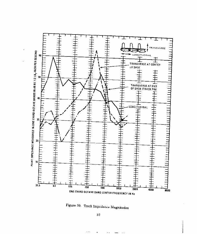
The upper track strand impedance magnitudes are shown in Figure 39. In the frequenciesof primary interest (between 125 and 500 Hz) the upper track strand behaves substantially as ifit were a mass in response to forces perpendicular to its kngth.
The transverse impedance magnitude ac the center of the track shoes is about 10 dD greaterthan that at the track pins at frequencies between 80 and 315 Hz. The impedance magnitudesare nearly the same above 315 liz. At below 200 Hz, the longitudinal impedance exceeds thetwo measured transverse impedances.
36
- -TRANSE S
0 60 *-* LONGITUDINAL
I ~~~~ TRANSVERS AT C N EC- IIJF SHOIE
0
0
W
LOGTUIA
0ucj
3-
C28.
205E315 - 2010020
0080ON-HR CA ED N CNE R Q ECUNH
Fiue3. Tjub! pdirM giue
m3

One way to reduce the transmission rf vibration into the hull is to 3 sert a cushion betweenthe hull and the idler or sprocket. From equations B-i and B-2 of A pendix B, it can be de-duced that these cushions, being of low impedance, -thould contact thC L, ack at the location ofits highest impedance. Namely, this is at the center of the track shoes.
Significant conclusions based directly on the impedance and vibration measurements are
below:
(1) For a given amplitude of horizontal and vertical force applied to the idler wheel rim, the re-sulting interior nuise is approximately equal in the 250 Hz octave band; but th3 verticalforce produced about 5 dB more noise in the 125 and 500 Hz bands.
(2) A given horizontal force at the sprocket rim, when averaged from 100 'c 630 liz, willproduce only 2 dB less interior noise than will the same vertical force.
(3) A given vibratory force applied at either the left or right sprocket will result in approxi-mately equal interior noise. Therefore, the engine compartment does not attenuate noiseinduced by the right sprocket.
(4) Idler or sprocket compliances should act on the certer of each track shoe for the optimumvibration isolation effect.
(5) The track is quite "hard" (has high impedance) below 200 Hz to motion parallel to thetrack strand. Even small accelerations in this direction will be associated with relativelyhigh forces on the idler or sprocket.
(6) Vibration kainig lh K horizontal an- vertical axes must be controlled for effective noise re-duction since significant horizontal and vertical accelerations are both present. An effec-tive noise reducing compliant idler or sprocket should include both tangential as well asradial compliance.
(7) The present rubber track inner pads reduce idler noise at 400 Hz and above, while the rub-ber sprocket tires significantly attenuate vibration at 630 Hz and above.
38

NOISE REDUCTION ESTIMATES OF COMPLItNT IDLER RIMS AND
HUBS
BACKGROUND
Recent research suggests that increased compliance at the idler or sprocket rims effectivelyreduces the huU vibration ",hich causes interior noise (References 7, 12, and 13). Of particularinterest is a practical noise reduction technique reported in Reference 13. Tie report docu-ments a 5 dB unweighted noise reduction by giving the steel idler rim a rounded or crownedcontour. This achieved an increased compliance by effectively utilizing the rubber inner trackpads as a cushion. A sketch of two other complie~nt rim and hub concepts appears in Figure 40.It should be understood that in a practical design, the compliant elements would probably berecessed beneath the idler rim for protection.
0 a. Rim
b. Hub and Rim
NOT[: I FI E XPOSED COIl SPI ; r - , ' , .........WUMPIANT LLEMLNTS FOR I ILUSTA ION PURPOSE b OL Y
Figure 40. Compliant Rim and Hub Concepts
39

ESTIMATION OF NOISE REDUCTIONS
To develop a better understanding of how much wheel rim compliance would achieve thenoise reduction goal, two separate analyses were made as a part of this program. In addition,the results are compared to the independent theory for predicting interior noise from velocityof impact developed in Reference 13. These analyses are reviewed below:
Simplified Vibration Isolator Analysis
For this analysis, the wheel rim compliance was considered to act as a simpie vibrationisolator or cushion acting in the radial direction. The vibration isolation effectiveness (Figure41) in one-third octave bands was calculated by using the track and idler rim impedance datafrom Impedance and Transfer Function Measurement. Production Mil3 track-to-idlerstiffness is 60,000 lbf/inch. The 60K lbf/inch curve of Figure 41 is the dynamic stiffness ofthe M113 idler.
The vibration isolator calculations were then repeated for an idler having both rim and hubcompliance, this time utilizing both the hub and idler/track impedance measurements and as-suming rim mass of 30 lbs and a rim compliance of J4,000 pounds per inch. The resultingisolator efficiency versus frequency values 'ire plotted ,n Figure 42. The analysis proceduresare presented in greater detail in Appendix B.
Vibration isolator theory predicts that reduction ot M113 idler and sprocket noise to thenoise goal is possible. However, the compliances required may not be achievable in practice.
Compater-Assisted Force Analysis
The computer graphics (Appendix C) show estimated noise levels for both vertical and hori-zontal forces. Horizontal and vertical forces were calculated in one-third octave bands forvarious rim compliances. The idler rim siiffnesses in the radial and tangential directions wereassumed to be equal. Interior noise estimates were derived from these calculated forces byusing the horizontal and vertical force-to-noise transfer functions from Impedaace and Trans-fer Function Measurements. The separate noise estimates due to horizontal and verticalforces were A-weighted and combined on an energy basis to obtain a total noise estimate(Figure 43).
In the analysis of the two softest idler and sprocket rims, the computer generated a ratherwide (20 + dB) scatter of data between track shoes. Therefore, the 23,000 and 3,000 pound perinch data in Figure 43 may not be accurate. Also, although the sprocket noise estimates agreevery well with actual measurements, the idler data are 14 dB(A) too high at 30 mph. Thiscould be due to the preliminary analysis, or to the transfer functions utilized.
40

f
I
10-
PARAMETER:2 ~TR ACK-JO -IDLE R
STIFFNESS (LBfIINCH)
0 _ _
LU _ _
_ 60K
U-
36K0
z
LA_
WU-EQIE
Ujcc (SO LATO R14
U-U-
0
I -
31.5 63 125 250 Soo 1000 2000
1/3 OCTAVE BAND CENTER FREQUENCIES IN Hz
Figure 41. Effect of Rini Stiffness on Isolator Efficiency with Infinitely Stiff Hub
41

t -10------ FT V1 T TF T
c i~
C IDLER HUB
- STIFFNESS
__ - (LB/N C H)U.10
60 K (M 113)36 K
I23K,. \14K
8 KU. -
2_0 30
L&
c31.5 63 125 250 500 1000 2000 40f0 9
11/3 OCTAVE BAND CENTER FREQUENCIES IN HZ,I
Figure 42. Effect of Hub Stiffness on Isolator Efficiency with 14K LBf/inchIdler/Rim Stiffness
Simplified Impact Force A nalysit
The simplified impact force am.iysis is a third noise reduction estimate techninue, At thepresent stage of development, this method will predict C-weighted noise level changes whichwould result from the design parameters which chang(. the track block mass, idler-track inter-face compliance, or track block velocity of impact. The resulting relationship between noiselevel and compliance is 3 dB per halving of the total stiffness between the idler wheel and thetrack shoe effective mass. Details of the procedure and assumptions made are contained inRefercic 13.
According to the impact force estimate, the benefit of improved compliance is cushioning ofthe track impacts on the idler. However, no noise reduction is assigned to other vibrationisolati, effects which may reduce higher frequencies more effectively than lower frequencies.An A-weighted noise reduction estimate would then be expected to increase more rapidly than3 dB per haiving of stiffness had these effects been considered.
42

130 I- I T1 T II IF -F- l11
120 \ -"
MEASURED IDLER IDLER COMPUTERDEPENDENT NOISE PREDICTION
-'N,. FORCE OF IMPACT -: -" PREDICTION (REF 13)
"*u,, SPROCKET- " COMPUTER-
z 100
COMPLIANT IDLERRIMWITH NON-C tOMPLIANT HUB-
'ISOLATOR THEORY
00COMPLIANT IDLER HUB 2- WITH RIM STIFFNESS~~OF 14,000 LBf/NCH-- ISOLATOR THEORY-
100 SO 20 10 5 2 1 0.5
IDLER RADIAL STIFFNESS (K Ibf/inch)
Figure 43. Predicted A-Weighted Noise Levels for CompliantIdler or Sprocket Rims and Hubs at 30 MPH.
43

Measured idler noise reductions correlate very well with the Impact Velocity Analysis pre-dictions. Up to 5 dB C-weighted noise reducion was predicted, and th'en demonstrated, on anM113 APC by softening the effective :dler rim compliance from 71,000 lbs/inch to 32,000lbs/inch and increasing the idler diameter from 17.25 to 21.00 inches. Only C-weighted datawere measured.
Figure 43 summarizes the predictions made by the simplified isolator analysis, the comput-er-assisted force analysis, and the impact velocity methods.
In all three of the above noise estimation techniques, no provision is made for possiblesteel-on-steel impacts at the sprocket. This omission is justified for the Ml 13 because most ofthe track vibration forces are exerted on a rubber cushion mounted to the sprocket carrier,rather than on the steel sprocket eeth.
This fact was demonstrated in an experiment where the interior noise was not reduced afterremoval of the sprocket teeth. During these measurements, the vehicle was tethered to a teststand so that the tracks did not touch the ground (Reference 7). That the steel-on-steel impactsare relatively minor in the M 113 and MICV was also confirmed by results of independent testsat FMC and in conversations with FMC track and suspension engineers. However, M113'swith double pin tracks do not have such cushions and sprocket impacts may generate higherinterior noise levels.
CONCLUSIONS BASED ON NOISE REDUCTION ESTIMATES
All three estimates show a noise reduction for decreased stiffness at the wheel rim. Forstiffnesses above 25,000 pounds per inch, the force analysis and simplified vibration isolatoranalysis predict similar noise reductions of 4.5 dB(A) with halving of stiffness. The velocity ofimpact analysis predicts a 3 dB(C) noise reduction for the same stiffness change.
At the present stage of development, none of the three individual noise reduction estimatesalone create a completely convincing prediction of the effects of increased compliance on in-terior noise. However, considered together, it is evident that increasing the compliance at theidler and sprocket rims can significantly reduce interior noise. These. estimates, along withexperimental results documented in Reference 13, yield the conclusion that interior noise willbe reduced about 4 dB(A) for each alving of rim stiffness.
44

APPENDIX A
LIST OF INSTRUMENTATION AND DATA DEVELOPED
Running Tests
" Lockheed Electronico Store 4, 4-channel FM tape recorder
" Two General Radio Sound Level Meters, Model 1933, equipped with two General RadioModel 1962 1/2" electret condener microphones on extension cables
" Gen.eral Radio Microphone Calibrator, Model 1562
* Six CEC Accelerometers, Model 4-281-001
" Four Endevco Type 2221D Accelerometers, with Type 2641 Charge Followers
" General Radio Vibration Calibrator, Model 1557A
" Ectron Model 418 Strain Gage Signal Conditioner
" Weston Model 750 DC Tachometer Generator, driven by a Track Test 5th Wheel
* DC Tachometer Genei tor, driven by final drive input member
* Esterline Angus X-Y Recorder, Model 2411 TB
* Hewlett-Packard 1/3 Octave Band Analyzer
Impedance and Transfer Function Measurements
* Two Bruel & Kjaer 1" Microphones, Type 4131, with random incidence correctors
" Two Bruel & Kjaer Sound Level Meters, Type 2209
* Two Bruel & Kjaer Octave Band Filters, Type 1613
" Goodman 50 lb Shaker
• Wilcoxon lnridance Head, Model Z-602
* General Radio Pink Noise Generator Model 1382
" B&K 1/3 Octave Band Filter, Type 1616
" General Radio 1/3 Octave Band Analyzer, Type 1564A
* Nagra IV-SI Magnetic Tape Recorder
* Honeywell SAI-2 Real Time Arnaiyzer/Digital Averager
45
DATA DEVELOPED
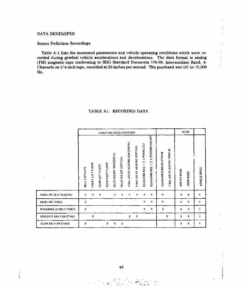
Source Definition Recordings
Table A-1 lists the measured parameters and vehicle operating conditions which were re-corded during gradual vehicle accelerations and decelerations. The data format is analog
(FM) magnetic tape conforming to IRIG Standard Document 106-66, Intermediate Band, 4-Channels on 1/4-inch tape, recorded at 30-inches per second. The passband was DC to 10,000Hz.
TABLE Al. RECORDED DATA
VIBRATION (ACCELERATION) N31SE
< a_ -x
z
2 c4r a'-
SPROCKETC WN LY3 SAD
0 CICfr
:D Ir W -j C3 0C0 ~
IDLER ON LY-ON STAND X X X x x X
46
4 f~90- '- - z
I- ~~ uJ o ..0 J a .a 0 I 0-a u

Source Definition Analysis
Octave band and one-third octave band data were developed from the tape rec rdings formost of the runs and are in the form of graphs of octave band level versus vehicle speed(octave band data) or numerical listings (one-third octave band data).
Impedance and Noise Transfer Function Data
Impedance and noise transfer function values were developed from measurements of force,acceleration, and sound pressures. Transducer signals were recorded on tape (2-channel,direct, at 7-1/2 inches per second) for possible future reference.
High Speed Movies
Approximately 4,400 feet of 16-mm Ektachrome EF film was used to record idler andsprocket track engagement at various track tensions and vehicle speeds. This footage wasedited into a 400-foot reel containing sections of each run.
Computer Program
A digital computer program was developed to predict the motion of and the forces exertedby a single track shoe as it engages a wheel. The compliance between the wheel and track maybe varied to determine the effect on noise. Inputs are the speed, track pi ch, track bushingsprxing rates, wheel radius, track shoe ms3s, track shoe moment of inertia, and the measu-edhorizontal and vertical vibratory force-to-noise transfer functions. In the present form, theoutputs are graphs of instantaneous forces exerted on the wheel and one-third octave bandnoise levels.
REFEIENCES
1. "T91E3 Type Rubber Mounted Sprockets with Harris Products Co, #69001 Rubber Bush.ings," G. L. Benson, Cadillac Motor Car Division - General Motors Corporation, Cleve-land Tank Plant (Test and Development Department TE-20), Report No. 137, June 17,1952.
2. "Rubber Tired Sprocket Hub (International Harvester Company Design) Effect on T 141Vehicle Vibration," Warren J. Young, Cadillac Motor Car Division - General MotorsCorporation, Cleveland Tank Plant (Test and Development Department TE-20), Report1201, March 11, 1954.
3. "Vibration Comparison of Four Types of Tracks," J. R. Prior, Cadillac Motor Car Division-G ne.rn Motors Co rporati.'on, C'le....elo..d T~ ~. Tt and D,.,,upi.ii.. Department
TE-20), Feport 1203, January 12, 1956.
47

4, "Durability Test of International Hariester Rubber Tired Hub and Sprocket Assemblies,"
L. W. Hoberecht, Cadillac Motor Car Division - General Motors Corporation, ClevelandTank Plant (Test and Development Department TE-20), Report No. 850, Test Requestedby hiternational Harvester Company for M75 Vehicle, May 20, 1954.
5. "Engineering Testing Division Automotive Branch Report on Noise and VibratiGn Test ofM113 Armored Personnel Carrier with Standard and Short Pitch Tracks," Ronald P.Lenert, Ordnance Test Activity, Development and Proof Services, Aberdeen ProvingGrounJ, Maryland, Report No. DPS/OTA-166, September 1962.
6. "Automotive Division Report on Component Development Test of Wire-Link Track, Test-
ed in Comparison with Standard T130 Forged Track," John P. Sobczyk, Development andProof Services, Aberdeen Proving Ground, Maryland, Report No. DPS-.850, DA ProjectNo. 548-12-001, February 1963.
7. "Development of Measurement Techniques for the Analysis of Tracked Vehicle Vibrationand Noise," Charles L. Bates and Cecil R. Sparks, Southwest Research Institute, SWRIProject No. 04-1421, Contract DA 23-072-AMC-144 (T), October 1964.
8. "MICV XM723 Test Report: Internal Noise Survey of the Prototype Vehicle," R. B. Hare,Ordnance Engineering Division, FMC Corporation, FMC OED Technical Report 2762,Contract DAA E07-73-C-0100, October 1964.
9. " High-Frequency Vibration Isolation," E. E. Ungar and C. W. Dietrich, Journal of Soundand Vibration, April 1966, Volume 4, Part 2, page 224.
10. "XM 551 Noise Reduction Program - Phase I," J. R. Wiley, General Motors Proving
Ground, Milford, Michigan, MPG 187, P.O. No. NEP-63571-KM and NEP-63570-KM,June 13, 1966.
11. "Return Idler Wheels: Various Designs Compared for Durability and Effect on Vehicle
Noise and Vibration Levels," R. N. Bibbens, Ordnance Engineering Division, FMC Cor-
poration, FMC OED Technical Report 722, October i969.
12. "Tracked Vehicles: Noise and Vibration Control Study Using a Reduced Scale Model,"Thomas R. Norris, Bolt Beranek and Newman Inc., San Fran.isco, Caliiornia, BBN Tech-
nical Report No. 3031, prepared for Mr. Donald Rees, U. S. Army Tank Automotive Com-mand, Warren, Michigan, Report 12099.
13. "Study of Track-Idler Engagement and Its Effect on Interior Noise," T. B. Van Wyk, FMCCorporation, San Joss, California, Technical Report 2976, April 1976.
14. "Noise Levels in the Passenger Areas of a Standard and a Product Improved M113A1 Ar-
mored Personnel Carrier," Howard H. Holland, Jr., U. S. Army Human Engineering1 t,-,-aorat Ahnrrlin Prnv;n'r(-.rniind Mnrvland 1,pt.tor Ranart. Nn 1 A Orxtlh r 1470
48

APPENDIX B
ANALYSIS OF ISOLATION EFFECTIVENESSES OF COMPLIANT IDLER RIMS AND HUBS
Calculation of Noise Reduction of Compliant Rim
In this appendix, the noise reduction of compliarce at the idler or sprocket rim is estimatedby a simple linear analysis based on the vibration isolation effectiveness of the compliance,and on iml- -.dance measurements. The noise reduction of an idler or sprocket wheel with anadditional compliance at the hub is also calculated, again based on impedance measurements.For purposes here, the idler and sprocket are considered identical, as sprocket tooth contact isnot a major noise source. Only the idler noise reduction is estimated; the sprocket noise reduc-tions would, in general, be similar.
The simplified linear analysis described below was used to e alculate the noise reductions ofthe compliant rim design. The formulae for isolator effectiveness are takei, from Ungar andDietrich (Reference 9). The simplified physical model used is shown in Figure 40. To simplifythe calculations, the entering track shoe is the only one in contact with the idler wheel, andonly vertical forces are considered. Tangential forces are assumed to be zero. In this simplifiedmodel, the track shoe impact velocity against the wheel is assumed to be constant, regardlessof compliance changes.
The required inputs to this noise level estimate are:
(1) Impedance magnitudes measured on an M113 idler rim and track, and
(2) Idler noise levels measured in an M113 vehicle.
For a simple conceptual model, where motions along only one line are considered and wherethe mass of the compliant element has no significant effect, the isolation effectiveness obeys
E=1+ MI.MS + MR
where M I denotes the mobility (i.e. the complex ratio of vibration velocity to force) of theresilient element (the "isolator"), MS the mobility of the track (the vibration source), and MRthe mobility of the idler spindle (the receiver) (Reference 9). The vibration amplitudes of theidler spindle are considered to be proportional to those of the hull. In general, all of themobilities are complex numbers. However for purposes here, the mobility of the resilientelement is take" to be that of an undamped massless spring:
MI = iw/k
which is purely imaginary, where k denotes the stiffness of the resilient element, w representsthe radian frequency, and i =,-1.
In addition, the idler spindle impedance is assumed to be purely real, and was determinedby experimental measurements shown in Figure B-1. The assumption of a real impedance atthe idler spindle is plausible because at frequencies above 100 Hz, the frequency interval be-
49

tween hull modes is expected to be smaller than the bandwidth associated with a modalresponse (for an estimated hull loss factor of 0.02). In other words, the hull responds as if itwere an infinite plate which has a purely real mobility (Reference 9).
The absolute value of the track mobility was taken from the data presented in Figure 39,which was derived from measurements made at the track pins. The real component of trackimpedance taken as Re1MsJ = 0.01 in/sec-lbf, corresponding to the lowest damp;--measured, and the imaginary component was calculated so that the absolute va.corresponds to Figure 39.
U - I
___ 50___HORIZONTAL
: 501 - -- _---
0C) 0
E-. CDU.,
I p R V E CAL
_ _il I I I l I _ _ _ _ 1_ 1 i
- 40 - . -_ _ _
S30
?1.5 63 125 250 500 1000 2000 4000 8000ONE-THIRD OCYAVE BAND CENTER FREUUENsY IN Hz
Figure BI. Vertical and Horizontal Left Idler Spindle Impedance Measured with IdlerWheel Removed
This model is naive in several respects, especially in that the measured impedance is for astraight rack section, while the actual track in the region of interest is curved around the idler.Also, for v'er. . compliances, the amount of impacting against the idler may vary in unpre-
dictable ways.
The simplified mod,!l is conservative in that the track ,obility value used in calculations isthe greatest measured, which is at the track pins. I ar, ictual design can support -, track atthe center of each block rather than at the pins, the mobility is an average of 10 dB lower, and a,rpatfer is'lator ei.ectivencss is obtained.
The predicted noise reduction of this model was shown in Figure 43 in Section 4. A rimcompliance of 5000 lbsf/inch gives 20 dB(A) which would be a very significant noise reductionif achieved in a producible idler. A very soft idler rim may not be achievable in practice owing
50

to track recentiop, debris ingestion, and durability tradeoffs. Preliminary concepts show thatmaterials are available which satisfy the application; however, only field experience can pro-vide a certain answer. In an actual idler design, it is unlikely that over 20 dB will be achievedbecause of wave effects in isolators, track guide scrub, and other effects.
Idler Noise Reduction by Compliance at the Idler Hub or Spindle
To achieve large noise reductions, rather than further increase the idler rim and track innerpad compliance as described above, the center of the idler wheel is an alternate compliancelocation that offers several advantages. First, the present track-idler rim might be basicallyunchanged, thus retaining a simple, proven mechanical system. Second, the noise reductionis more predictable than for compliance at the rim because the track trajectory will be un-changed. Third, the isolated mass of the idler wheel itself greatly enhances high frequencyvibration reduction.
A possible compliant idler hub (or spindle) concept was shown on the lower portion ofFigure 40. The compliant element could be attached to the wheel or to the spindle. If attachedto the wheel, it is reverse stressed by track tension forces with each revolution. Alternately, ifthe compliance is attached to the spindle so that it does not rotate, it is not reverse stressedby track tension with each revolution. In this case, it is subject to much less fatigue and heat-ing.
The compliant hub cfficiency was calculated by using the two stage isolator f.). "iula pre-sented by Ungar and Dietrich in Reference 9:
EZ 1 + 1 (MI1 + M 12 ) +AEMS + MR
A (MI 1 + MS ) (M12 -+- MR )
Mm (MS -;- MR)
where MI1 is the track-rim compliance mobility, M12 is the hub compliance mobility, Mm isthe idler mass mobility, andAE represents tho increase hi noise reduction due to two, insteadof one, compliar:. elements separated by a mass. For present purposes, both compliances areassumed to have no damping. Other terms and approximations are the same as given earlierfor idler rim formulae.
The A-weighted predicted noise reduction was shown in Figure 43 which compares rimcompliance to hub compliance predihtions. The compliant hub design o'fers a great deal morehigh-frequency noise reduction than the compliant rim alone, but is about equal to the rimconcept in the 63 and 125 Hz octave bands for the same total compliance. The abrupt"corner" of the attenuation cL.rves is the resonance between the track and idler rim. Thiscorner could 'e moved to a lowo'r frequency by increasing the compliance at the idler rim orhub.
'The soft hub noise reduction was calculated assuming that the track pad and rim could bemodified to achieve 14,000 lbsf/in. compliance, which is much softer than the present 60,000
51

lbsf/in. This lower rim compliance appears to be practical from materials considerations, butconsiderable development may be required to achieve acceptable durability parameters.
The very large vibration reductions shown for 250 Hz and above are due to the idler wheelmass, which is assumed to be rigid. Any practical idler, however, is only rigid at belowperhaps 250 Hz, and will resonate at a number of higher frequencies. The net effect of theresonances is to increase high frequency vibration transmitted. This is not serious since themajor problem will be in the 125 Hz octave band, which will not be effectively isolated.
The baseline for all compliant idler noise reduction estimates is for the existing M113 60,000lbsf/in idler-track compliance. For practical purposes, sprocket noise reductions arepractically identical, except the baseline is 49,000 lbsf/inch owing to the rubber impact tire.
52

APPENDIX C:
TRACK SHOE IMPACT NOISE ANALYSIS
Approach
Impacts and vibration of track sho s against the sprocket and idler wheel cause the wheelsto vibrate. These vibrations are transmitted to the hull, and vibrations of the hull producenoise in the vehicle interior. The first step toward understanding and predicting this interiornoise is determining the track shoe/wheel interaction forces. Once these forces are known,tiey can be combined with force-to-noise transfer functions to calculate the resulting noise.
Analysis of th93 track shoe/wheel interaction forces is complicated, not only because of theintrate geometry, but also because of te nonlinearity in these forces due to the track shoeslosing contact with the wheel during pa:'ts of their motion. (The compliance at the wheel rimmay be modeled as a linear spring when it is in compression, but it can provide no restoringforces when contact is lost.) Because cf this complexity, computer-assisted numerical analysisof the interaction forces is indicated. The previously mentioned transfer functions can best bedetermined experimentally.
Dynamical Model
In the present analysis, whi-h is intended to include only the major f3atures of the dynamicsystem, the wheel of radius R is assumed to rotate with constant angular velocity (a and tovibrate only by a negligible amount compared to the track shoes.
The present analysis investigates the track/whe3l interaction forces that are generated as afinite length of track (made up of 60 shoes) moves over the wheel, The midpoint of the firstshoe is taken to be rigidly fixed to the wheel rim, ard the last shoe is taken to move uniformlyat the vehicle speed V along a line tangential to the wheel. The remaining shoes are permittedto move under the influence of their inertias, shoe-to-shoe interaction forces, and shoe/wheelinteraction forces.
In the present analysis, initial conditions are imposed on the system, and the subse uentmotions of the system are calculated for a finite time period. Although one would ideally liketo determine what happens when steady state is reached, this calculation would require an ex-penditure of considerable more computer time and associated costs.
The present analysis is limited to periods of motion that are short enough so that waves re-flected from the last track shoe (Figure C-i) do not return to the wheel during the periodconsidered. Therefore, damping effects in the system (as analyzed here) play no significantrole and have been omitted from consideration. However, this omission restricts the maxi-mum duration of the sinmulation.
53

2 K 6 59 60
Figure C-i: Basic Features of Dynamic Model at t = 0
Equations of Motion
The equations of motion are readily obtained by Lagrange's method, which uses theLagrangian f-ction L defined as
L = T(, , ; t)-V(qq ,I ..q, ; t) (C-')
where T denotes the kinetic energy and V the potential energy of thc system, the qs representthe generalized coordinates ue.-sd to describe the system, and the dot indicates differentiationwith respect to time. The S differential equations of motion then are obtained from ReferencesC-1 and C-2.*
-, = 1,2,.. .,S. IC-2)dt ((TI 3qs
The generalized coordinates are comprised of the spatial coordinates x, (t), y, (t) of thecenter of the N shoes and of the angular coordinates On(t) of the shoes (Figure C-2). The totalkinetic energy of the system then may be written as
2 =- 2 k"2 +_ .2 ±) + 1 2] (C-3)
nm 2
*References are given at the end of this appendix.
54

where m and I denote the mass and the mass moment of inertia of a shoe. Note that the firstshoe makes no contribution to the vibrational kinetic energy, because this shoe is assumed tobe rigidly connected to the wheel.
V
Xn0 W- ,, € .......... ..
VY(t)
-X
Figure C-2: Coordinates of Nth Shoe
If one neglects the contribution due to gravity, one may consider the potential energy V asmade up of a contribution VB from compression of the bushing springs, of a contribution VQfrom torsion of these springs, and of a contribution VC from compression of the compliantlayer between the track and the wheel:
V = Vi +V +V c (C-4)
The displacement of the left end of shoe n with rospect to the right end of the shoe n-1 maybe taken as equal to the elongation ASn of the elastic element of the bushing between theseshoes, if this displacement (and the elongation) is zero under zero tension. In view of the defi-nition of the link coordinates,
F L 2 Li 2
(AS 1 = - X. -2 (cos On + os - - 2 (sin n 4-Sill )j ((C-5)
One thus may evaluateN
-a K i (AS")2 (C'-6)2 n=2
where KB denotes the extensional stifiness of a bushing.
One way write the torsional potential energy stored in the bushing between the nth and(n-I )th shoe in terms of the relative rotation (0n - ,i ) of the two shoes as
55

NVQ = Q E (0, -On-I ) 2 (C-7)
n=2
where Q denotes the rotational stiffness of a bushing.
For the present analysis it is convenient to assume that the compliant layer between thetrack and wheel acts only at the center of each shoe and has the same stiffness KC, no matterin what direction the shoe is displaced relative to the wheel's rim, provided that the shoe'scenter is pushed inside the rim radius R. If the shoe center is outside this radius, the shoe isassumed to have lost contact, and the effective interface stiffness is zero. Then one may write
N
vc KC E - + (y, - Rsin 0 0 )2] (C-8)n=2n
where0 for x 2 +yn 2 >R' (C-9)
and 1 otherwise
7r
0 - + 2(n -2) + cot . (C-10)n0 2
Here xno = R cos 0 n0 and yn0 = R sin 0nO are the coordinates of a shoe in contact at the rimat equilibrium (i.e,, with the compliant layer not displaced), wit h 0no representing the angularposition of this shoe along the wheel, and 1 = arc tan(L/2R).
One may then obtain an expression for V by substituting Eqs. C-6, C-7, and C-8 into Eq.C-4, and one may determine the Lagrangian function L by substituting this result and Eq. C-3into Eq. C-1. Finally, one may apply Eq. C-2 to obtain the equations of motion:
x *- W cL (x n - R cos 0 n W B 2 2xn Xn .I X n I -. -(c cs f 1 -Xcos n1)
n2 0 3 1 n -LIn 1 - (Csi On-I - sin€n +)
Yn -W c2(yn - R SinOno)-WB2 [2Yn- Yn-I -Yn+l-L (S1n- ni On+)
on -W '20 n -I ni n+ I snnX~ - nl
-- COS 0n(Yn+l -Yn-I ±2 [sin on( 2 coson + cos 0 _ + co:> .n+l)
-Cos n (2 sin On + sin n-I + sin 0 n+1 )J (C-11)
66

where the frequency parameters w( , 40B, and wQ are related to the stiffness and inertiaparameters through w2C = KC/m, w zB = KB/m, and 2Q - Q/.. These equations apply forall shoes, except the first and the last, whose motions are prescribed.
Initial Conditions and Constraints
For all but the first shoe the initial conditions are taken as
O(0) 0 x,,(0) (n-2)L + (N -1)AL , y1 (0) R
(0) = 0 (o) -V , 1(0) 0 (c-12)
where
AL = P/KB (C-13)
denotes the axial displacement of one shoe relative to the next due to the applied tension P,with KB representing the previously mentioned bushing stiffness. The average vehicle speedV is related to the track pitch L, wheel radius R, and angular speed W, through
w LV = - (C-14)
2a
The constraint imposed on the fizst shoe is that it remains rigidly connected to the wheel, sothat for all values at t,
7r0 (t)- + 20C + Wt , x1 (t) = Rcoso , y, (:) = R sin , (C-15)
The last (i.e., the 60th) shoe is taken as constrained to move tangentially to the wheel, sothat
,o(1) 0 x6 0 (t) = S8L+59AL-Vt , Y60() = R . (C-16)
Computtational Considerations
The differential equations of motion may be solved by use of finite difference techniques(References C-3 and C-4), which require one to select time steps and the total time to be con-sidered.
In order to provide an accurate solution, the time step t must be small; its correspondingfrequency f = I/At must be at least three times the highest frequency of interest. Thus, if thisfrequency is 2500 Hz, the time step must be no greater than 1 .33 X 1 0 ' sec. In order to insurestability of the solution, the frequency f must also be several times larger than the highestresonance frequoncy of the system. For a resonance frequency of 520 Hz (that can result from20 lb shoe masses oscillating between 140 Klbs/in. bushing springs), the foregoing choice ofA = 1.33 X 10⁻⁴ sec provides a more than adequate margin.
57

The total time To- No At for which the computation is carried out is limited by accuracy andcomputation time (cost) considerations. Accuracy requires that the interval To be long enoughso that to = 1/To is less than one half of the lowest frequency of interest. If the latter fre-quency is 32 Hz, then To must be at least 60 msec, and the required number of steps No >To/At= 45 .Computation system (Fast Fourier Transform) considerations require N o to be chosen
as an integral powex of 2; we Lherefore chooseN0 = 512, and take At = To/ No 0.117msec.
70 70 I I I I I I V '1 F T W TTIT V VFII I'1EXCITATION OF WHEEL:
VERTICAL -
:5 _ HORIZONTAL -Ii - -
" "7TF L S SL FL WHERE.'
SL SOUND PRESSURE LEVEL (dB, re 2 x 0-5 N/m2)
FL FORCE LEVEL (d, ro 1. LSF)
31.5 63 125 250 500 1000 2000 4000 8000ONE-1IHIRD OCTAVE BAND CENTER FREQUENCIES IN Hz (cps)
Figure C-3: Transfer Function for Sprocket Wheel Vibration to Noise in Crew Compartment
Since the computation time and cost increase with the number N of track shoes, it is advan-tageous to minimize the number of shoes included in the calculation. On the other hand, thetrack length must -e selected sufficiently great so that waves reflected from the last shoe willnot affect the motions of the first few shbes that are to be studied in detail. Since the phasevelocity of longitudinal waves in the M113 track may be estimated to be 818 ft/sec, such awave would in 60 msec traverse (818) (0.060) = 50 ft or about 100 half-foot long shoes. In thissame time interval, about 5 shoes interact with a wheel on a vehicle travelling at 30 mph.Thus, selection of N = 60, corresponding to a 120 shoe round-trip length for a wave beginningat the wheel, ensures that the motions of shoes 2 through 6 are unaffected by the returning re-flected wave.
Computed Results
In accordance with the foregoing discussion a 60 shoe track string was considered for a total....... 0 .flAA.s. A. 6Lut, etp U L 0. i7 msec was used, and calculations were
carried out for 512 time points.
58
.., , . . - . . . - .'L " ... -
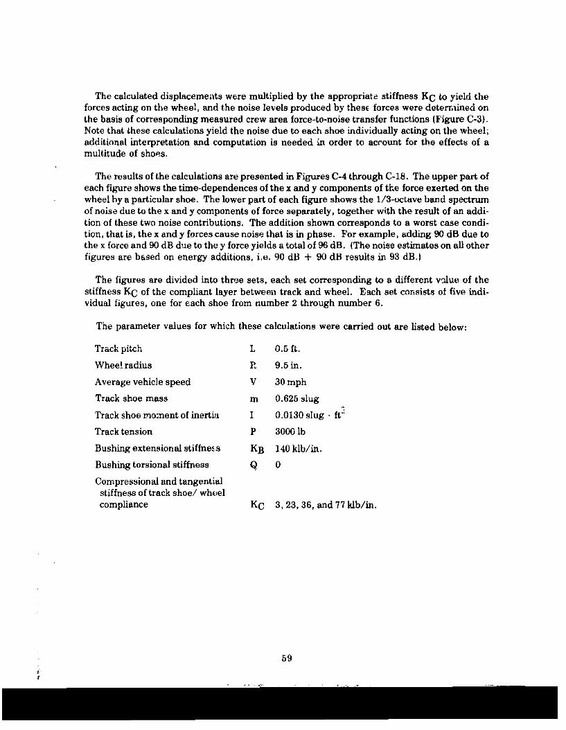
The calculated displacements were multiplied by the appropriate stiffness KC to yield theforces acting on the wheel, and the noise levels produced by thesE forces were determined onthe basis of corresponding measured crew area force-to-noise transfer functions (Figure C-3).Note that these calculations yield the noise due to each shoe individually acting on the wheel;additional interpretation and computation is needed in order to account for the effects of amultitude of shops.
The results of the calculations are presented in Figures C-4 through C-18. The upper part ofeach figure shows the time-dependences of the x and y components of the force exerted on thewheel by a particular shoe. The lower part of each figure shows the 1/3-octave band spectrumof noise due to the x and y components of force separately, together with the result of an addi-tion of these two noise contributions. The addition shown corresponds to a worst case condi-tion, that is, the x and y forces cause noise that is in phase. For example, adding 90 dB due tothe x force and 90 dB due to the y force yields a total of 96 dB. (The noise estimates on all otherfigures are based on energy additions, i.e. 90 dB + 90 dB results in 93 dB.)
The figures are divided into three sets, each set corresponding to a different vilue of thestiffness KC of the compliant layer between track and wheel. Each set consists of five indi-vidual figures, one for each shoe from number 2 through number 6.
The parameter values for which these calculations were carried out are listed below:
Traci. pitch L 0.5 ft.
Wheel radius R 9.5 in.
Average vehicle speed V 30 mph
Track shoe mass m 0.625 slug
Track shoe moment of inertia I 0.0130 slug . ft-
Track tension P 3000 lb
Bushing extensional stiffne.&s KB 140 klb/in.
Bushing torsional stiffness Q 0
Compressional and tangentialstiffness of track shoe/ wheelcompliance KC 3, 23, 36, and 77 klb/in.
59

6000
x-COMPONENT
'.-COMPONENT
LU- L - -- ,' - --
a t IU. It .
L6 6
-6000 I
TIME (MSECS)
Figure C-4a: Time Histories of Forces Exerted on Wheel by Track Shoe Number 2(2300 ibf/ijzsch)
120
Noise due tox - FORCE:2y - FORCE:
BOTH:
e" 100,," --"
/ 'ii ',L4
2
60 I [Ai1111 I I 11111I I t12 4 102 2 4 103 2 4 104
1/3 OCTAVE BANDS (Hz)
Figure C-4b: Interior Noise Spectra Associated with Forces of Figure C-4a
60

6000
x-COMPONENT
y -COMPONENT
I 0
IL.
-6000J I0 30 60
TIME (MSECS)
Figure C-5a: Time Histories of Forces Exerted on Wheel by Track Shoe No. 3(23,000 lbf/irich)
120
4Noise due tox-FORCE:
Z:L y-FORCE:C-4 BOTH:
IG
4L
20 4 V 102 ,2 4 103,2"1
m,,J •,-A
~ 61
2
60A) l _11 .1 1 I I I IJi l ,11 _1_L .
2 4 t02 2 4 03 2 415
1/3 OCTAVE BAMIJ$ (Hze)
Figure C-5b: Associated Noise Spectra
61

6000
x -COMPONENTV -a CMPONENT
0cc
-0 - I 30 60
TIME (MSECS)
Figure C-6a: Time Histories of Forces Exerted on Wheel by Track Shoe No. 4(23,000 ibf/inch)
120
Noise due tox -FORCE-
:3 y - FORCE:R BOTH:
U.,
-I
L'NI
60 - -4 ILII
I~1 OCTAVE1 BAD Mz) ii
Figure C-61): Associated Noise Spectra
62

6000x - COMPONENT
COMPONENT
~%
lL
-6000 I i I0 30 so
TIME (MSECS)
Figure C-7a: Time Histories of Forces Exerted on Wheel by Track Shoe No. 5(23,000 lbf/inch)
120
Noise due to
x -FORCE:2EZk. y - FO RCE:
.'= r ABOTH:
100
LU
_jI
~Vcc 80
2 4 102 2 4 103 2 4 104
1/3 OCTAVE BANDS (Hz)
figure C-'b: Associated Noise Spectra
63

6000
x - COMPONENT
y- COMPONENT
0
-6000
0 30 60TIME (MSECS)
Figure C-8a: Time Histories of Forces Exerted on Wheel by Track Shoe No. 6(23,000 lbf/.'nch)
120
Cj"= Noise due to
x - FORCE:y - FORCE:
BOTH:
0100 f7
.A.
00
60 LIL L J. I _1111I11 I 11 l _._ Ilf1lit
2 4 102 2 4 1U3 2 4 in,
1/3 OCTAVE BANDS (Hz)
Figure C-8b: Associated Noise Spectra
J
64

x - COMPONENTy - COMPONENT
cc'
03 60
TIME MSECS)
Figure C-9a: Time Histories of Forces Exerted on Wheel by Track Shoe No. 2(36,000 lbf/inch )
120
Noise due toz x - FORCE:y - FORCE: - -
~ 100
La
-j
uJ
-- 800L.
60 1lll 1 11 1_. 111J J2 4 102 2 4 103 2 4 104
1/3 OCTAVE BANDS (Hz)
Figure C-9b: Associated Nnisqe Spo,'trn
65
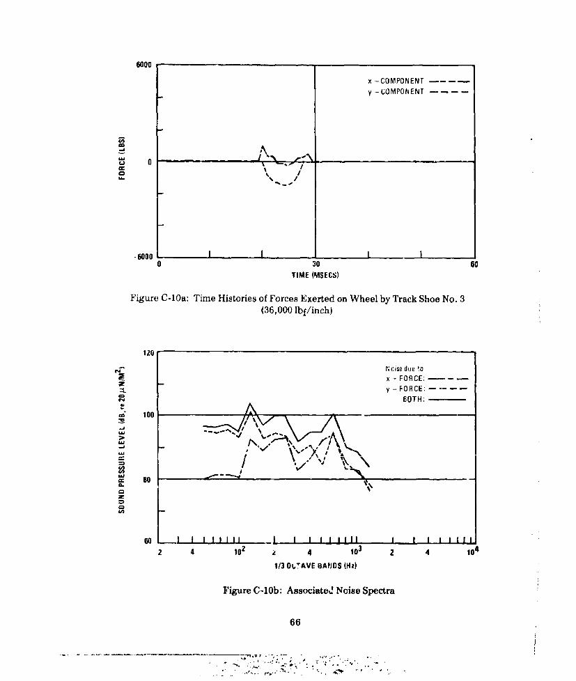
6000
x-COMPONENT
y-COMPONENT
- 0LLIN
oe /
30 60TIME (MSECS)
Figure C-10a: Time Histories of Forces Exerted on Wheel by Track Shoe No. 3
(36,000 lbf/inch)
120
Noise due lox - FORCE;y -FORCE: -.... .
BOTH;
100
Ld,\
2 80 04102-0
0
I I I ! ! I I - I I!I I II I I 1 I II f
2 4 102 4 103 2 41 4
1/3 0TAVE BAHDS (Hz)
Figure C-lOb: Associated Noise Spectra
66
........... ....

6000
x-COMPONENTV - COMPONENT
'a 0ir.
-woo II I0 30 60
TIME (MSECS)Figure C-1la: Time Histories of Forces Exerted on Wheel by Track Shoe No. 4
(36,000 lbf/inch)
120
4 Noise due tox - FORE:y - FOIhCE;
- A%
a.
60 I I ll1 i I I 111il_ 1 I I2 4 102 2 4 103 2 4 104
1/3 OCTAVE BANDS (lz)
Figure C-1b: Associated Noise Spectra
67

6000
x - COMPONENTy - COMPONENT
0
-J -"U\
'%I,
-6000 I I I I0 30 60
TIME (MSECS)
Figure C-12a: Time Histories of Forces Exerted on Wheel by Track Shoe No. 5(36,000 lbf/inch)
120
Noise due to
x - FORCE:
C BOTH:0 100
-4 V C §SO
\A-
60 . ILJ I I I I1 1I
2 4 102 2 4 103 2 4 104
113 OCTAVE BANDS (Hz)
Figure C-12b: Associated Noise Spectra
68
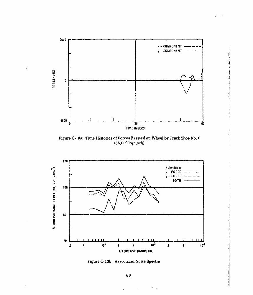
GOOD
x-COMPONENTy - COMPONENT
0 A-
-6000 I ---_ -----0 30 60
rIME (MGECS)
Figure C-13a: Time Histories of Forces Exerted on Wheel by Track Shoe No. 6(36,000 lbf/inch)
120
Noise due tox -FORCE:== . y -FORCE:
~BOTH:
4N
C,
c 100
.j
S I,
2 4 102 2 4 10 3 2 4 104
113 OCTAVE BANDS NOz
Figure C-13b: Associavd Noise Spectra
60

6000
x-COMPONENT
y-COMPONENT
;II
A
I|
III
I-cI
-6000 I I I0 30 60TIME (MSECS)
Figure C-14a: Time Histories of Forces Exerted on Wheel by Track Shoe No. 2(77,000 lbf/inch)
120
Noise due toX -FORCE--y -FORCE:
\ BOTH:
* 0 I I I I I I IJ I l i I i I I I I J i I I _
4 2100
700
S
_jI I I 1 1
670

6000
x-COMPONENT
-COMPONENT
-
ICI
0 30 soTIME (MSECS)
Figure C-15a: Time Histories of Forces Exerted on Wheel by Track Shoe No. 3
(77,000 Ibf/inch)
120
Noise due tox -FORCE--
z ~VFO0R CE:r4'~ ' ~ BOTH:
CD 1003 .-
\/j %%
30
2 4 102 2 4 13 2 410
1/3 OCTAVE BANDS (Hz)
Figure C-15b: Associated Noise Spectra
71

6000
x-CJMPONENT
y -COMPONENT
,#4 'I
I A 01V
0 30 Go
TIME (MSECS)
Figure C-16a: Time Histories of Forces Exerted on Wheel by Track Shoe No. 4(77,000 lbf/inch)
120
Noise due tox -FORCE:--
BOTH:
au
so2. 4 0 0 0
1/ CAEBNSwz
Fiur 306-Aeeitd~--
a.2

6000
x -COMPONENTY-COMPONENT .
-Iw ______________________ __ _/
o M.. \ I
'I
-6000 I j0 30 60
TIME (MSECS)
Figure C-17a: Time Histories of Forces Exerted on Wheel by Track Shoe No. 5(77,000 lbf/inch)
120
4Noise due tox -FORCE:
: /\y -FORCE:SBOTH:
.00
2 4 102 2 4 103 2 4 104
1/30OCTAVE 8AUtlS IHz)
Figure C-17b: Associated Noise Spectra
73
'a \ f''i

6000x-COMPONENTY-COMPONENT
mv
~J 0
0 30 60TIME (MSECS)
Figure C-18a-: Time Histories of Forces Exerted on Wheel by Track Shoe No. 6(77,000 lbf/inch)
120
Noise due tox - FORCE:--y -FORC-:;
LU
2 402 2 4103 2 4 104
1/3 OCTAVE BANDS (Hz)
A: !& Te A P;d-&CrLft.LaW4A AN 'LW~ *JjJVWA t
74

Discussion of Results
By observing each of Figures C-4a through C-18a, it may be noted that the interaction forcesvanish during some time intervals; this occurs when the track shoe "bounces" out of contactwith the wheel.
As a track shoe arrives at the wheel, the y-component of the force is negative; i.e., the shoepushes the wheel downward. Similarly, the y-force becomes predominantly positive when theshoe is on the underside of the wheel.
Inspection of Figures C-4 through C-18 reveals khat, in general, none of the shoes achievessteady-state motion within the 60 msec period to which the computation applies.
Because steady-state motion was not achieved in the present analysis, the 1/3 octave bandspectra show wide variationa Letween track shoes for each rim compliance. Possible reasonsfor this variation include:
1. The second track shoe, being attached to the first shoe which is "welded" to the wheel,undergoes motions not typical of subsequent shoes.
2. The third through sixth track shces exert forces during only the latter portion of the analysistime window because of their lack of contact with the wheel. This would lower vibration
force delivered to the wheel.
3. Because of severe bouncing of the track shoes on the wheel, the spectra do not representsteady-state conditions. For example, the third shoe for the 36,000 pound per inch compli-ance run was in contact with the wheel for only about 10 milliseconds out of a 60 milli-second-long simulation.
4. Although the spectra vary greatly, most have a peak of 630 Hz that may correspond to reso-nanmes between track shoes (or shoes and the wheel). This peak may be due to the lack ofdamping in the present simplified model.
5. The tangential compliance exerts its force as if the track were registered to the wheel. Thatis. the track shoes will be fixed to locations of the wheel rim that are exactly one track shoelength apart for the uncompressed (zero displacement) compliance, as may be seen byexaminatiGn of Equations 8, 9, and 10. When the compliant rim is compressed by track ten-sion, the effective circumference is reduced, so that the wheel tends to "get ahead" ofthe track. However, upon initial contact of a shoe on the wheel, a powerful tangential forceis suddenly exerted on each shoe and the wheel which forces the track to abruptly "catchup" to the position specified by Equation 10. This artifact of the present simulation wouldtend to increase the vibration exerted on the wheels and, therefore, results in exaggeratednoise estimates. That the simulated wheel exerts a strong initial jerk on the track is con-finmed by the positive "x" force shown upon initial impact, on Figures C-4a through C-18ai.In many cases this horizontal jerk cxceeds the vertical impact force.
6. The transfer functions are for purely radial forces, rather than for a combined tangentialand radial force. In the actual vehicle, a horizontal, purely tangential force component at
75

the rim will cause both "x" and "y" radial forces to be exerted on the spindle due to theasymmetrical contact of the track on the side of the wheel. The change of sound level esti-mates due to this force coupling is unknown, but is thought to be small.
The averaged A-weighted sprocket noise predictions for 77,000, 36,000, 23,000 and 3,000pounds per inch rim compliances which appear or) Figure 44 of the main report were derivedas follows: First, for track shoes three through six, the noise due to the "x" and "y" forceswere summed on an energy basis for each 1/3 octave band to obtain an overall sprocket noisespectrum due to each shoe. Next, these three spectra were summed to obtain the averagespectrum for each simulated rim compliance value. Finally, the spectra were A-weighted andsummed.
The idler noise predictions were obtained by adjusting each horizontal and vertical third-octave band of sprocket noise. This accounts for the differences between the idler andsprocket force-to-noise transfer functions. The combining of noise due to the 'x" and "y"forces and averaging between links was then carried out in the same way as for the sprocket.The validity of this procedure depends on the assumptions that the track engages the idler andthe sprocket in a similar manner, that the slight difference in wheel diameters is not signifi-cant, and that the sprocket teeth do not affect the engagement dynamics. In Figure 43, the A-weighted sprocket noise level at 77,000 lb/inch is seen to be in excellent agreement with themeasured sound level at 60,000 lb/inch. However, the predicted idler noise level at 77,000lb/inch is 126 dBJA), which is 14 dB above the me-esured value of 112 dB(A) for the nominally60,000 pound per inch standard idler. At the present, it is uncertain why this discrepancy islarge compared to the excellent sprocket noise estimate. Possible reasons are that theforce-to-noise transfer functions are incorrect and that the computer enalysis requires furtherdevelopment.
Figures C-19 and C-20 present the predicted idler and sprocket noise spectra.
120
l.A V
--110 V. - .-
~\ -/w ' /77000 LBSI CH RIi COMPLIANC (115 dBA)
100 .--- !"36000 LRSIINCH RIM COMPLIANCE (108 dBA) ,. o-
23000 LBS/INCH HIM COMPLIANCE (107 dBA)i3000LBS/INCH RIM COMPLIANCE (103dBA)
i.5 63 125 250 500 itUU .u0 42afiONE-THIRD OCTAVE BAND CENTER FREQUENCIES IN Hz
Figure C-19: Computer Estimate of Noise in the Crew Area Due to One IdlerWheel at 30 MPH
76

120 -
2%-J
>,
100
-77000 RBINC IM COMPLIANCE (126 dCA)- 36000 LBS/INCH RIM COMPLIANCE (115 dBA) - .. _
-23000 LBS!INCH RIM COMPLIANCE (117 dBA)- 3000 LBS/INCH RIM COMPLIANCE (112 dBA) i
31.5 63 125 250 500 1000 2000 4000 8000ONE-THIRD OCTAVE BAND CENTER FREQUENCIES IN Hz (cps)
Figuze C-20: Computer Estimate of Noise Spectra in the Crew Area Due to OneSprocket Wheel at 30 MPH
Significant trends that may be observed on these figures are that. 1) the average noisereduction generally increased with softer rim compliance, 2) some noise reduction occurred formost frequencies, and 3) higher frequencies were reduced more than lower frequencies.
It may be expected that if damping were included in the model, development of steady-statebehavior would be accelerated because reflected waves from the far end of the track would bedamped. Improved analyses should take account of damping, should consider extended trackaction on both sides of the wheel, and should include impr,-oved desriptions ofthe t"a..k/wheelinteraction.
REFERENCES
C-1. K. Symon, Mechanics, Addison Wesley, Chap. 9, 1960.
C-2. G. Fowles, Analytical Mechanics, Holt, Rinehart and Winston, Chap. 11.
C-3. M. Salvatori and M. Baron, Numerical Methods in Engineering, Prentice Hall, 1961,Sec. I and U.
C-4. D. Potter, Computational Physics, Wiley, 1973, Chap. II.
C-5. See Ref. 2. see'. 11 7 pn 9150-95
77