Embed Size (px)
Citation preview

3GPP TS 23.003 V7.1.0 (2006-09)
Technical Specification
3rd Generation Partnership Project;Technical Specification Group Core Network and Terminals;
Numbering, addressing and identification(Release 7)
GLOBAL SYSTEM FOR
MOBILE COMMUNICATIONS
R
The present document has been developed within the 3rd Generation Partnership Project (3GPP TM) and may be further elaborated for the purposes of 3GPP. The present document has not been subject to any approval process by the 3GPP Organizational Partners and shall not be implemented. This Specification is provided for future development work within 3GPP only. The Organizational Partners accept no liability for any use of this Specification.Specifications and reports for implementation of the 3GPP TM system should be obtained via the 3GPP Organizational Partners' Publications Offices.
HTC/ZTE Exhibit 1013

3GPP
3GPP TS 23.003 V7.1.0 (2006-09)2Release 7
Keywords GSM, UMTS, addressing
3GPP
Postal address
3GPP support office address 650 Route des Lucioles - Sophia Antipolis
Valbonne - FRANCE Tel.: +33 4 92 94 42 00 Fax: +33 4 93 65 47 16
Internet http://www.3gpp.org
Copyright Notification
No part may be reproduced except as authorized by written permission. The copyright and the foregoing restriction extend to reproduction in all media.
© 2006, 3GPP Organizational Partners (ARIB, ATIS, CCSA, ETSI, TTA, TTC).
All rights reserved
HTC/ZTE Exhibit 1013-2

3GPP
3GPP TS 23.003 V7.1.0 (2006-09)3Release 7
Contents
Foreword ............................................................................................................................................................ 6
1 Scope ........................................................................................................................................................ 7 1.1 References ............................................................................................................................................................. 7 1.1.1 Normative references ...................................................................................................................................... 7 1.1.2 Informative references ..................................................................................................................................... 9 1.2 Abbreviations ........................................................................................................................................................ 9 1.3 General comments to references ......................................................................................................................... 10 1.4 Conventions on bit ordering ............................................................................................................................... 10
2 Identification of mobile subscribers ....................................................................................................... 10 2.1 General ................................................................................................................................................................ 10 2.2 Composition of IMSI .......................................................................................................................................... 10 2.3 Allocation principles ........................................................................................................................................... 11 2.4 Structure of TMSI ............................................................................................................................................... 11 2.5 Structure of LMSI ............................................................................................................................................... 12 2.6 Structure of TLLI ................................................................................................................................................ 12 2.7 Structure of P-TMSI Signature ........................................................................................................................... 13
3 Numbering plan for mobile stations ....................................................................................................... 13 3.1 General ................................................................................................................................................................ 13 3.2 Numbering plan requirements ............................................................................................................................ 13 3.3 Structure of MS international PSTN/ISDN number (MSISDN) ....................................................................... 14 3.4 Mobile Station Roaming Number (MSRN) for PSTN/ISDN routeing .............................................................. 14 3.5 Structure of Mobile Station International Data Number .................................................................................... 15 3.6 Handover Number ............................................................................................................................................... 15 3.7 Structure of an IP v4 address .............................................................................................................................. 15 3.8 Structure of an IP v6 address .............................................................................................................................. 15
4 Identification of location areas and base stations ................................................................................... 15 4.1 Composition of the Location Area Identification (LAI) .................................................................................... 15 4.2 Composition of the Routing Area Identification (RAI) ..................................................................................... 16 4.3 Base station identification ................................................................................................................................... 16 4.3.1 Cell Identity (CI) and Cell Global Identification (CGI) ............................................................................... 16 4.3.2 Base Station Identify Code (BSIC) ............................................................................................................... 17 4.4 Regional Subscription Zone Identity (RSZI) ..................................................................................................... 17 4.5 Location Number ................................................................................................................................................ 18 4.6 Composition of the Service Area Identification (SAI)....................................................................................... 18
5 Identification of MSCs, GSNs and location registers ............................................................................ 18 5.1 Identification for routeing purposes.................................................................................................................... 18 5.2 Identification of HLR for HLR restoration application ..................................................................................... 19
6 International Mobile Station Equipment Identity and Software Version Number ................................. 19 6.1 General ................................................................................................................................................................ 19 6.2 Composition of IMEI and IMEISV .................................................................................................................... 19 6.2.1 Composition of IMEI .................................................................................................................................... 19 6.2.2 Composition of IMEISV ............................................................................................................................... 20 6.3 Allocation principles ........................................................................................................................................... 20
7 Identification of Voice Group Call and Voice Broadcast Call Entities .................................................. 20 7.1 Group Identities ................................................................................................................................................... 20 7.2 Group Call Area Identification ........................................................................................................................... 21 7.3 Voice Group Call and Voice Broadcast Call References ................................................................................... 21
8 SCCP subsystem numbers ...................................................................................................................... 22 8.1 Globally standardized subsystem numbers used for GSM/UMTS .................................................................... 22 8.2 National network subsystem numbers used for GSM/UMTS ........................................................................... 22
HTC/ZTE Exhibit 1013-3

3GPP
3GPP TS 23.003 V7.1.0 (2006-09)4Release 7
9 Definition of Access Point Name ........................................................................................................... 23 9.1 Structure of APN ................................................................................................................................................. 23 9.1.1 Format of APN Network Identifier ............................................................................................................... 23 9.1.2 Format of APN Operator Identifier ............................................................................................................... 23 9.2 Definition of the Wild Card APN ....................................................................................................................... 24 9.2.1 Coding of the Wild Card APN ...................................................................................................................... 24
10 Identification of the Cordless Telephony System entities ...................................................................... 24 10.1 General description of CTS-MS and CTS-FP Identities .................................................................................... 24 10.2 CTS Mobile Subscriber Identities ...................................................................................................................... 24 10.2.1 General ........................................................................................................................................................... 24 Composition of the CTSMSI ............................................................................................................................................... 25 10.2.3 Allocation principles ..................................................................................................................................... 25 10.2.4 CTSMSI hexadecimal representation ........................................................................................................... 25 10.3 Fixed Part Beacon Identity ................................................................................................................................. 25 10.3.1 General ........................................................................................................................................................... 25 10.3.2 Composition of the FPBI .............................................................................................................................. 26 10.3.2.1 FPBI general structure ............................................................................................................................. 26 10.3.2.2 FPBI class A ............................................................................................................................................ 26 10.3.2.3 FPBI class B ............................................................................................................................................ 26 10.3.3 Allocation principles ..................................................................................................................................... 27 10.4 International Fixed Part Equipment Identity ...................................................................................................... 27 10.4.1 General ........................................................................................................................................................... 27 10.4.2 Composition of the IFPEI ............................................................................................................................. 27 10.4.3 Allocation principles ..................................................................................................................................... 28 10.5 International Fixed Part Subscription Identity ................................................................................................... 28 10.5.1 General ........................................................................................................................................................... 28 10.5.2 Composition of the IFPSI .............................................................................................................................. 28 10.5.3 Allocation principles ..................................................................................................................................... 28
11 Identification of Localised Service Area ................................................................................................ 29
12 Identification of PLMN, RNC, Service Area, CN domain and Shared Network Area .......................... 29 12.1 PLMN Identifier .................................................................................................................................................. 29 12.2 CN Domain Identifier ......................................................................................................................................... 29 12.3 CN Identifier ....................................................................................................................................................... 30 12.4 RNC Identifier ..................................................................................................................................................... 30 12.5 Service Area Identifier ........................................................................................................................................ 30 12.6 Shared Network Area Identifier .......................................................................................................................... 30
13 Numbering, addressing and identification within the IP multimedia core network subsystem ............. 31 13.1 Introduction ......................................................................................................................................................... 31 13.2 Home network domain name .............................................................................................................................. 31 13.3 Private user identity ............................................................................................................................................ 31 13.4 Public User Identity ............................................................................................................................................ 32 13.5 Public service identity (PSI) ............................................................................................................................... 32 13.6 Anonymous User Identity ................................................................................................................................... 32
14 Numbering, addressing and identification for 3GPP System to WLAN Interworking .......................... 33 14.1 Introduction ......................................................................................................................................................... 33 14.2 Home network realm .................................................................................................................................................... 33 14.3 Root NAI ............................................................................................................................................................. 33 14.4 Decorated NAI .................................................................................................................................................... 34 14.4A Fast Re-authentication NAI ................................................................................................................................ 34 14.5 Temporary identities .................................................................................................................................................... 35 14.6 Alternative NAI ............................................................................................................................................................ 35 14.7 W-APN ................................................................................................................................................................ 35 14.7.1 Format of W-APN Network Identifier .......................................................................................................... 35 14.7.2 Format of W-APN Operator Identifier ......................................................................................................... 36 14.7.3 Alternative Format of W-APN Operator Identifier ...................................................................................... 36
15 Identification of Multimedia Broadcast/Multicast Service .................................................................... 37 15.1 Introduction ......................................................................................................................................................... 37 15.2 Structure of TMGI .............................................................................................................................................. 37
HTC/ZTE Exhibit 1013-4

3GPP
3GPP TS 23.003 V7.1.0 (2006-09)5Release 7
15.3 Structure of MBMS SAI ..................................................................................................................................... 37
16 Numbering, addressing and identification within the GAA subsystem ................................................. 37 16.1 Introduction ......................................................................................................................................................... 37 16.2 BSF address ......................................................................................................................................................... 38
17 Numbering, addressing and identification within the Generic Access Network .................................... 38 17.1 Introduction ......................................................................................................................................................... 38 17.2 Network Access Identifiers ................................................................................................................................. 38 17.2.1 Home network realm ..................................................................................................................................... 38 17.2.2 Full Authentication NAI ............................................................................................................................... 39 17.2.3 Fast Re-authentication NAI........................................................................................................................... 39 17.3 Node Identifiers ................................................................................................................................................... 39 17.3.1 Home network domain name ........................................................................................................................ 39 17.3.2 Provisioning GANC-SEGW identifier ......................................................................................................... 40 17.3.3 Provisioning GANC identifier ...................................................................................................................... 40
Annex A (informative): Colour Codes .................................................................................................. 42
A.1 Utilization of the BSIC ........................................................................................................................... 42
A.2 Guidance for planning ............................................................................................................................ 42
A.3 Example of PLMN Colour Codes (NCCs) for the European region ...................................................... 43
Annex B (normative): IMEI Check Digit computation .................................................................... 44
B.1 Representation of IMEI .......................................................................................................................... 44
B.2 Computation of CD for an IMEI ............................................................................................................ 44
B.3 Example of computation ........................................................................................................................ 44
Annex C (normative): Naming convention ........................................................................................ 46
C.1 Routing Area Identities .......................................................................................................................... 46
C.2 GPRS Support Nodes ............................................................................................................................. 47
C.3 Target ID ................................................................................................................................................ 47
Annex D (informative): Applicability and use of the ".3gppnetwork.org" domain name ............... 48
Annex E (normative): Procedure for sub-domain allocation ........................................................... 49
Annex F (informative): Change history ............................................................................................... 50
HTC/ZTE Exhibit 1013-5

3GPP
3GPP TS 23.003 V7.1.0 (2006-09)6Release 7
Foreword This Technical Specification (TS) has been produced by the 3rd Generation Partnership Project (3GPP).
The present document defines the principal purpose and use of International Mobile station Equipment Identities (IMEI) within the digital cellular telecommunications system and the 3GPP system.
The contents of the present document are subject to continuing work within the TSG and may change following formal TSG approval. Should the TSG modify the contents of the present document, it will be re-released by the TSG with an identifying change of release date and an increase in version number as follows:
Version x.y.z
where:
x the first digit:
1 presented to TSG for information;
2 presented to TSG for approval;
3 or greater indicates TSG approved document under change control.
y the second digit is incremented for all changes of substance, i.e. technical enhancements, corrections, updates, etc.
z the third digit is incremented when editorial only changes have been incorporated in the document.
HTC/ZTE Exhibit 1013-6

3GPP
3GPP TS 23.003 V7.1.0 (2006-09)7Release 7
1 Scope The present document defines the principal purpose and use of International Mobile station Equipment Identities (IMEI) within the digital cellular telecommunications system and the 3GPP system.
The present document defines:
a) an identification plan for mobile subscribers in the GSM system;
b) principles of assigning telephone and ISDN numbers to MSs in the country of registration of the MS;
c) principles of assigning Mobile Station (MS) roaming numbers to visiting MSs;
d) an identification plan for location areas, routing areas, and base stations in the GSM system;
e) an identification plan for MSCs, SGSNs, GGSNs, and location registers in the GSM system;
f) principles of assigning international mobile equipment identities;
g) principles of assigning zones for regional subscription;
h) an identification plan for groups of subscribers to the Voice Group Call Service (VGCS) and to the Voice Broadcast Service (VBS); and identification plan for voice group calls and voice broadcast calls; an identification plan for group call areas;
i) principles for assigning Packet Data Protocol (PDP) addresses to mobile stations;
j) an identification plan for point-to-multipoint data transmission groups;
k) an identification plan for CN domain, RNC and service area in the UTRAN system.
l) an identification plan for mobile subscribers in the WLAN system.
1.1 References
1.1.1 Normative references
The following documents contain provisions which, through reference in this text, constitute provisions of the present document.
• References are either specific (identified by date of publication, edition number, version number, etc.) or non-specific.
• For a specific reference, subsequent revisions do not apply.
• For a non-specific reference, the latest version applies. In the case of a reference to a 3GPP document (including a GSM document), a non-specific reference implicitly refers to the latest version of that document in the same Release as the present document.
[1] 3GPP TS 21.905: "3G Vocabulary".
[2] 3GPP TS 23.008: "Organization of subscriber data".
[3] 3GPP TS 23.060: "General Packet Radio Service (GPRS); Service description; Stage 2"
[4] 3GPP TS 23.070: "Routeing of calls to/from Public Data Networks (PDN)".
[5] 3GPP TS 24.008: "Mobile Radio Interface Layer 3 specification; Core Network Protocols; Stage 3".
[6] 3GPP TS 29.060: "GPRS Tunnelling protocol (GTP) across the Gn and Gp interface".
HTC/ZTE Exhibit 1013-7

3GPP
3GPP TS 23.003 V7.1.0 (2006-09)8Release 7
[7] 3GPP TS 43.020: "Digital cellular telecommunications system (Phase 2+); Security related network functions".
[8] void
[9] 3GPP TS 51.011: " Specification of the Subscriber Identity Module - Mobile Equipment (SIM - ME) interface".
[10] ITU-T Recommendation E.164: "The international public telecommunication numbering plan".
[11] ITU-T Recommendation E.212: "The international identification plan for mobile terminals and mobile users".
[12] ITU-T Recommendation E.213: "Telephone and ISDN numbering plan for land Mobile Stations in public land mobile networks (PLMN)".
[13] ITU-T Recommendation X.121: "International numbering plan for public data networks".
[14] IETF RFC 791: "Internet Protocol".
[15] IETF RFC 2373: "IP Version 6 Addressing Architecture".
[16] 3GPP TS 25.401: "UTRAN Overall Description".
[17] 3GPP TS 25.413: "UTRAN Iu Interface RANAP Signalling".
[18] IETF RFC 2181: "Clarifications to the DNS Specification".
[19] IETF RFC 1035: "Domain Names - Implementation and Specification".
[20] IETF RFC 1123: "Requirements for Internet Hosts -- Application and Support".
[21] IETF RFC 2462: "IPv6 Stateless Address Autoconfiguration".
[22] IETF RFC 3041: "Privacy Extensions for Stateless Address Autoconfiguration in IPv6".
[23] 3GPP TS 23.236: "Intra Domain Connection of RAN Nodes to Multiple CN Nodes".
[24] 3GPP TS 23.228: "IP Multimedia (IM) Subsystem – Stage 2"
[25] Void
[26] IETF RFC 3261: "SIP: Session Initiation Protocol"
[27] 3GPP TS 31.102: "Characteristics of the USIM Application."
[28] Void
[29] 3GPP TS 44.118: "Radio Resource Control (RRC) Protocol, Iu Mode".
[30] 3GPP TS 23.073: "Support of Localised Service Area (SoLSA); Stage 2"
[31] 3GPP TS 29.002: "Mobile Application Part (MAP) specification"
[32] 3GPP TS 22.016: "International Mobile Equipment Identities (IMEI)"
[33] Void
[34] Void
[35] 3GPP TS 45.056: "CTS-FP Radio Sub-system"
[36] 3GPP TS 42.009: "Security aspects" [currently not being raised to rel-5 – Pete H. looking into it]
[37] 3GPP TS 25.423: "UTRAN Iur interface RNSAP signalling"
[38] 3GPP TS 25.419: "UTRAN Iu-BC interface: Service Area Broadcast Protocol (SABP)"
[39] 3GPP TS 25.410: "UTRAN Iu Interface: General Aspects and Principles"
HTC/ZTE Exhibit 1013-8

3GPP
3GPP TS 23.003 V7.1.0 (2006-09)9Release 7
[40] ISO/IEC 7812: "Identification cards - Numbering system and registration procedure for issuer identifiers"
[41] Void
[42] 3GPP TS 33.102 "3G security; Security architecture"
[43] 3GPP TS 43.130: "Iur-g interface; Stage 2"
[45] IETF RFC 3966: "The tel URI for Telephone Numbers"
[46] 3GPP TS 44.068: "Group Call Control (GCC) protocol".
[47] 3GPP TS 44.069: "Broadcast Call Control (BCC) Protocol ".
[48] 3GPP TS 24.234: "3GPP System to WLAN Interworking; UE to Network protocols; Stage 3".
[49] Void
[50] IETF RFC 4187: "EAP AKA Authentication".
[51] IETF RFC 4186: "EAP SIM Authentication".
[52] 3GPP TS 23.246: "Multimedia Broadcast/Multicast Service (MBMS); Architecture and functional description"
[53] IETF RFC 4282: 'The Network Access Identifier'.
[54] IETF RFC 2279: "UTF-8, a transformation format of ISO 10646".
[55] 3GPP TS 33.234: "Wireless Local Area Network (WLAN) interworking security".
[56] Void
[58] 3GPP TS 33.221 "Generic Authentication Architecture (GAA); Support for Subscriber Certificates".
[60] IEEE 1003.1-2004, Part 1: Base Definitions
[61] 3GPP TS 43.318: "Generic Access to the A/Gb interface; Stage 2"
[62] 3GPP TS 44.318: "Generic Access (GA) to the A/Gb interface; Mobile GA interface layer 3 specification"
[63] 3GPP TS 29.163: "Interworking between the IP Multimedia (IM) Core Network (CN) subsystem and Circuit Switched (CS) networks"
[64] IETF RFC 2606: "Reserved Top Level DNS Names"
1.1.2 Informative references
[44] "COMPLEMENT TO ITU-T RECOMMENDATION E.212 (11/98)", Annex to ITU Operational Bulletin No. 741 – 1.VI.200; This is published on the ITU-T website, whose home page is at http://www.itu.int/ITU-T/
[57] GSMA PRD IR.34 "Inter-PLMN Backbone Guidelines"
[59] Void
1.2 Abbreviations
For the purposes of the present document, the abbreviations defined in 3GPP TS 21.905 apply.
HTC/ZTE Exhibit 1013-9

3GPP
3GPP TS 23.003 V7.1.0 (2006-09)10Release 7
1.3 General comments to references
The identification plan for mobile subscribers defined below is that defined in ITU-T Recommendation E.212.
The ISDN numbering plan for MSs and the allocation of mobile station roaming numbers is that defined in ITU-T Recommendation E.213. Only one of the principles for allocating ISDN numbers is proposed for PLMNs. Only the method for allocating MS roaming numbers contained in the main text of ITU-T Recommendation E.213 is recommended for use in PLMNs. If there is any difference between the present document and the ITU-T Recommendations, the former shall prevail.
For terminology, see also ITU-T Recommendations E.164 and X.121.
1.4 Conventions on bit ordering
The following conventions hold for the coding of the different identities appearing in the present document and in other GSM Technical Specifications if not indicated otherwise:
- the different parts of an identity are shown in the figures in order of significance;
- the most significant part of an identity is on the left part of the figure and the least significant on the right.
When an identity appears in other Technical Specifications, the following conventions hold if not indicated otherwise:
- digits are numbered by order of significance, with digit 1 being the most significant;
- bits are numbered by order of significance, with the lowest bit number corresponding to the least significant bit.
2 Identification of mobile subscribers
2.1 General
A unique International Mobile Subscriber Identity (IMSI) shall be allocated to each mobile subscriber in the GSM/UMTS system.
NOTE: This IMSI is the concept referred to by ITU-T as "International Mobile Station Identity".
In order to support the subscriber identity confidentiality service the VLRs and SGSNs may allocate Temporary Mobile Subscriber Identities (TMSI) to visiting mobile subscribers. The VLR and SGSNs must be capable of correlating an allocated TMSI with the IMSI of the MS to which it is allocated.
An MS may be allocated two TMSIs, one for services provided through the MSC, and the other for services provided through the SGSN (P-TMSI for short).
For addressing on resources used for GPRS, a Temporary Logical Link Identity (TLLI) is used. The TLLI to use is built by the MS either on the basis of the P-TMSI (local or foreign TLLI), or directly (random TLLI).
In order to speed up the search for subscriber data in the VLR a supplementary Local Mobile Station Identity (LMSI) is defined.
The LMSI may be allocated by the VLR at location updating and is sent to the HLR together with the IMSI. The HLR makes no use of it but includes it together with the IMSI in all messages sent to the VLR concerning that MS.
2.2 Composition of IMSI
IMSI is composed as shown in figure 1.
HTC/ZTE Exhibit 1013-10

3GPP
3GPP TS 23.003 V7.1.0 (2006-09)11Release 7
MCC
Not more than 15 digits
3 digits 2 or 3
MNC MSIN
NMSI
IMSI
Figure 1: Structure of IMSI
IMSI is composed of three parts:
1) Mobile Country Code (MCC) consisting of three digits. The MCC identifies uniquely the country of domicile of the mobile subscriber;
2) Mobile Network Code (MNC) consisting of two or three digits for GSM/UMTS applications. The MNC identifies the home PLMN of the mobile subscriber. The length of the MNC (two or three digits) depends on the value of the MCC. A mixture of two and three digit MNC codes within a single MCC area is not recommended and is outside the scope of this specification.
3) Mobile Subscriber Identification Number (MSIN) identifying the mobile subscriber within a PLMN.
The National Mobile Subscriber Identity (NMSI) consists of the Mobile Network Code and the Mobile Subscriber Identification Number.
2.3 Allocation principles
IMSI shall consist of decimal digits (0 through 9) only.
The number of digits in IMSI shall not exceed 15.
The allocation of Mobile Country Codes (MCCs) is administered by the ITU-T. The current allocation is given in the COMPLEMENT TO ITU-T RECOMMENDATION E.212 [44].
The allocation of National Mobile Subscriber Identity (NMSI) is the responsibility of each administration.
If more than one PLMN exists in a country, the same Mobile Network Code should not be assigned to more than one PLMN.
The allocation of IMSIs should be such that not more than the digits MCC + MNC of the IMSI have to be analysed in a foreign PLMN for information transfer.
2.4 Structure of TMSI
Since the TMSI has only local significance (i.e. within a VLR and the area controlled by a VLR, or within an SGSN and the area controlled by an SGSN), the structure and coding of it can be chosen by agreement between operator and manufacturer in order to meet local needs.
The TMSI consists of 4 octets. It can be coded using a full hexadecimal representation.
In order to avoid double allocation of TMSIs after a restart of an allocating node, some part of the TMSI may be related to the time when it was allocated or contain a bit field which is changed when the allocating node has recovered from the restart.
In areas where both MSC-based services and SGSN-based services are provided, some discrimination is needed between the allocation of TMSIs for MSC-based services and the allocation of TMSIs for SGSN-based services. The discrimination shall be done on the 2 most significant bits, with values 00, 01, and 10 being used by the VLR, and 11 being used by the SGSN.
HTC/ZTE Exhibit 1013-11

3GPP
3GPP TS 23.003 V7.1.0 (2006-09)12Release 7
If intra domain connection of RAN nodes to multiple CN nodes as described in 3GPP TS 23.236 [23] is applied in the MSC/VLR or SGSN, then the NRI shall be part of the TMSI. The NRI has a configurable length of 0 to 10 bits. A configurable length of 0 bits indicates that the NRI is not used and this feature is not applied in the MSC/VLR or SGSN. The NRI shall be coded in bits 23 to 14. An NRI shorter than 10 bits shall be encoded with the most significant bit of the NRI field in bit 23.
The TMSI shall be allocated only in ciphered form. See also 3GPP TS 43.020 [7] and 3GPP TS 33.102 [42].
The network shall not allocate a TMSI with all 32 bits equal to 1 (this is because the TMSI must be stored in the SIM, and the SIM uses 4 octets with all bits equal to 1 to indicate that no valid TMSI is available).
To allow for eventual modifications of the management of the TMSI code space management, MSs shall not check if an allocated TMSI belongs to the range allocated to the allocating node. MSs shall use an allocated TMSI according to the specifications, whatever its value.
2.5 Structure of LMSI
The LMSI consists of 4 octets and may be allocated by the VLR. The VLR shall not allocate the value zero. The value zero is reserved to indicate that an LMSI parameter sent from the HLR to the VLR shall not be interpreted.
2.6 Structure of TLLI
A TLLI is built by the MS or by the SGSN either on the basis of the P-TMSI (local or foreign TLLI), or directly (random or auxiliary TLLI), according to the following rules.
The TLLI consists of 32 bits, numbered from 0 to 31 by order of significance, with bit 0 being the LSB.
A local TLLI is built by an MS which has a valid P-TMSI as follows:
bits 31 down to 30 are set to 1; and
bits 29 down to 0 are set equal to bits 29 to 0 of the P-TMSI.
A foreign TLLI is built by an MS which has a valid P-TMSI as follows:
bit 31 is set to 1 and bit 30 is set to 0; and
bits 29 down to 0 are set equal to bits 29 to 0 of the P-TMSI.
A random TLLI is built by an MS as follows:
bit 31 is set to 0;
bits 30 down to 27 are set to 1; and
bits 0 to 26 are chosen randomly.
An auxiliary TLLI is built by the SGSN as follows:
bit 31 is set to 0;
bits 30 down to 28 are set to 1;
bit 27 is set to 0; and
bits 0 to 26 can be assigned independently.
Other types of TLLI may be introduced in the future.
Part of the TLLI codespace is re-used in GERAN to allow for the inclusion of the GERAN Radio Network Temporary Identifier in RLC/MAC messages. The G-RNTI is defined in 3GPP TS 44.118 [29].
The structure of the TLLI is summarised in table 1.
HTC/ZTE Exhibit 1013-12

3GPP
3GPP TS 23.003 V7.1.0 (2006-09)13Release 7
Table 1: TLLI structure
31 30 29 28 27 26 to 0 Type of TLLI 1 1 T T T T Local TLLI 1 0 T T T T Foreign TLLI 0 1 1 1 1 R Random TLLI 0 1 1 1 0 A Auxiliary TLLI 0 1 1 0 X X Reserved 0 1 0 X X X Reserved 0 0 0 0 G G Part of the assigned G-RNTI 0 0 0 1 R R Random G-RNTI
'T', 'R', 'A' and 'X' indicate bits which can take any value for the type of TLLI. More precisely, 'T' indicates bits derived from a P-TMSI, 'R' indicates bits chosen randomly, 'A' indicates bits chosen by the SGSN, 'G' indicates bits derived from the assigned G-RNTI and 'X' indicates bits in reserved ranges.
2.7 Structure of P-TMSI Signature
The P-TMSI Signature consists of 3 octets and may be allocated by the SGSN.
The network shall not allocate a P-TMSI Signature with all 24 bits equal to 1 (this is because the P-TMSI Signature must be stored in the SIM, and the SIM uses 3 octets with all bits equal to 1 to indicate that no valid P-TMSI signature is available.
3 Numbering plan for mobile stations
3.1 General
The structure of the following numbers is defined below:
- the number used by a subscriber of a fixed (or mobile) network to call a mobile station of a PLMN;
- the network addresses used for packet data communication between a mobile station and a fixed (or mobile) station;
- mobile station roaming numbers.
One or more numbers of the ISDN numbering plan shall be assigned to a mobile station to be used for all calls to that station, i.e. the assignment of at least one MSISDN to a mobile station is mandatory.
NOTE: For card operated stations the ISDN number should be assigned to the holder of the card (personal number).
3.2 Numbering plan requirements
In principle, it should be possible for any subscriber of the ISDN or PSTN to call any MS in a PLMN. This implies that ISDN numbers for MSs should comply with the ISDN numbering plan in the home country of the MS.
The ISDN numbers of MSs should be composed in such a way that standard ISDN/PSTN charging can be used for calls to MSs.
It should be possible for each administration to develop its own independent numbering/addressing plan for MSs.
The numbering/addressing plan should not limit the possibility for MSs to roam among PLMNs.
It should be possible to change the IMSI without changing the ISDN number allocated to an MS and vice versa.
In principle, it should be possible for any subscriber of the CSPDN/PSPDN to call any MS in a PLMN. This implies that it may be necessary for an MS to have a X.121 number.
HTC/ZTE Exhibit 1013-13

3GPP
3GPP TS 23.003 V7.1.0 (2006-09)14Release 7
In principle, it should be possible for any fixed or mobile terminal to communicate with a mobile terminal using an IP v4 address or IP v6 address.
3.3 Structure of MS international PSTN/ISDN number (MSISDN)
MS international ISDN numbers are allocated from the ITU-T Recommendation E.164 numbering plan; see also ITU-T Recommendation E.213. The structure of the MS international ISDN number will then be as shown in figure 2.
mobile number
National (significant)
Mobile station international
ISDN number
CC NDC SN
Figure 2: Number Structure of MSISDN
The number consists of:
- Country Code (CC) of the country in which the MS is registered, followed by:
- National (significant) mobile number, which consists of:
- National Destination Code (NDC) and
- Subscriber Number (SN).
For GSM/UMTS applications, a National Destination Code is allocated to each PLMN. In some countries more than one NDC may be required for each PLMN.
The composition of the MS international ISDN number should be such that it can be used as a global title address in the Signalling Connection Control Part (SCCP) for routeing messages to the home location register of the MS. The country code (CC) and the national destination code (NDC) will provide such routeing information. If further routeing information is required, it should be contained in the first few digits of the subscriber number (SN).
A sub-address may be appended to an ISDN number for use in call setup and in supplementary service operations where an ISDN number is required (see ITU-T Recommendations E.164, clause 11.2 and X.213 annex A). The sub-address is transferred to the terminal equipment denoted by the ISDN number.
The maximum length of a sub-address is 20 octets, including one octet to identify the coding scheme for the sub-address (see ITU-T Recommendation X.213, annex A). All coding schemes described in ITU-T Recommendation X.213, annex A are supported in GSM and UMTS.
3.4 Mobile Station Roaming Number (MSRN) for PSTN/ISDN routeing
The Mobile Station Roaming Number (MSRN) is used to route calls directed to an MS. On request from the Gateway MSC via the HLR it is temporarily allocated to an MS by the VLR with which the MS is registered; it addresses the Visited MSC collocated with the assigning VLR. More than one MSRN may be assigned simultaneously to an MS.
The MSRN is passed by the HLR to the Gateway MSC to route calls to the MS.
The Mobile Station Roaming Number for PSTN/ISDN routing shall have the same structure as international ISDN numbers in the area in which the roaming number is allocated, i.e.:
HTC/ZTE Exhibit 1013-14
3GPP
3GPP TS 23.003 V7.1.0 (2006-09)15Release 7
- the country code of the country in which the visitor location register is located;
- the national destination code of the visited PLMN or numbering area;
- a subscriber number with the appropriate structure for that numbering area.
The MSRN shall not be used for subscriber dialling. It should be noted that the MSRN can be identical to the MSISDN (clause 3.3) in certain circumstances. In order to discriminate between subscriber generated access to these numbers and re-routeing performed by the network, re-routeing or redirection indicators or other signalling means should be used, if available.
3.5 Structure of Mobile Station International Data Number
The structure of MS international data numbers should comply with the data numbering plan of ITU-T Recommendation X.121 as applied in the home country of the mobile subscriber. Implications for numbering interworking functions which may need to be provided by the PLMN (if the use of X.121 numbers is required) are indicated in 3GPP TS 23.070 [4].
3.6 Handover Number
The handover number is used for establishment of a circuit between MSCs to be used for a call being handed over. The structure of the handover number is the same as the structure of the MSRN. The handover number may be reused in the same way as the MSRN.
3.7 Structure of an IP v4 address
One or more IP address domains may be allocated to each PLMN. The IP v4 address structure is defined in RFC 791 [14].
An IP v4 address may be allocated to an MS either permanently or temporarily during a connection with the network.
3.8 Structure of an IP v6 address
One or more IP address domains could be allocated to each PLMN. The IP v6 address structure is defined in RFC 2373 [15].
An IP v6 address may be allocated to an MS either permanently or temporarily during a connection with the network
If the dynamic IPv6 stateless address autoconfiguration procedure is used, then each PDP context, or group of PDP contexts sharing the same IP address, is assigned a unique prefix as defined in 3GPP TS 23.060 [3].
As described in RFC 2462 [21] and RFC 3041 [22], the MS can change its interface identifier without the GPRS network being aware of the change.
4 Identification of location areas and base stations
4.1 Composition of the Location Area Identification (LAI)
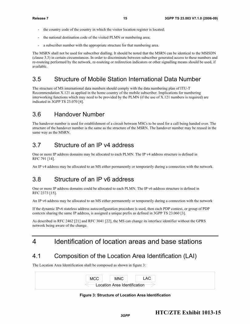
The Location Area Identification shall be composed as shown in figure 3:
Location Area Identification
MCC MNC LAC
Figure 3: Structure of Location Area Identification
HTC/ZTE Exhibit 1013-15

3GPP
3GPP TS 23.003 V7.1.0 (2006-09)16Release 7
The LAI is composed of the following elements:
- Mobile Country Code (MCC) identifies the country in which the GSM PLMN is located. The value of the MCC is the same as the three digit MCC contained in international mobile subscriber identity (IMSI);
- Mobile Network Code (MNC) is a code identifying the GSM PLMN in that country. The MNC takes the same value as the two or three digit MNC contained in IMSI;
- Location Area Code (LAC) is a fixed length code (of 2 octets) identifying a location area within a PLMN. This part of the location area identification can be coded using a full hexadecimal representation except for the following reserved hexadecimal values:
0000, and
FFFE.
These reserved values are used in some special cases when no valid LAI exists in the MS (see 3GPP TS 24.008 [5], 3GPP TS 31.102 [27] and 3GPP TS 51.011 [9]).
A specific GSM PLMN code (MCC + MNC) may be broadcast for mobile stations which are not compatible with SoLSA and which do not understand the exclusive access indicator (see 3GPP TS 23.073 [30]). The reserved value of the escape PLMN code is MCC = 901 and MNC = 08.
4.2 Composition of the Routing Area Identification (RAI)
The Routing Area Identification shall be composed as shown in figure 4:
Figure 4: Structure of Routing Area Identification
The RAI is composed of the following elements:
- A valid Location Area Identity (LAI) as defined in clause 4.1. Invalid LAI values are used in some special cases when no valid RAI exists in the mobile station (see 3GPP TS 24.008 [5], 3GPP TS 31.102 [27] and 3GPP TS 51.011 [9]).
- Routeing Area Code (RAC) which is a fixed length code (of 1 octet) identifying a routeing area within a location area.
4.3 Base station identification
4.3.1 Cell Identity (CI) and Cell Global Identification (CGI)
The BSS and cell within the BSS are identified within a location area or routeing area by adding a Cell Identity (CI) to the location area or routeing area identification, as shown in figure 5. The CI is of fixed length with 2 octets and it can be coded using a full hexadecimal representation.
The Cell Global Identification is the concatenation of the Location Area Identification and the Cell Identity. Cell Identity shall be unique within a location area.
HTC/ZTE Exhibit 1013-16

3GPP
3GPP TS 23.003 V7.1.0 (2006-09)17Release 7
MCC LACMNC CI
Location Area Identification
Cell Global Identification (CGI)
Figure 5: Structure of Cell Global Identification
4.3.2 Base Station Identify Code (BSIC)
The base station identity code is a local colour code that allows an MS to distinguish between different neighbouring base stations. BSIC is a 6 bit code which is structured as shown in Figure 6.
NCC BCC
PLMN colour code BS colour code
3 bits3 bits
Figure 6: Structure of BSIC
In the definition of the NCC, care should be taken to ensure that the same NCC is not used in adjacent PLMNs which may use the same BCCH carrier frequencies in neighbouring areas. Therefore, to prevent potential deadlocks, a definition of the NCC appears in annex A. This annex will be reviewed in a co-ordinated manner when a PLMN is created.
4.4 Regional Subscription Zone Identity (RSZI)
A PLMN-specific regional subscription defines unambiguously for the entire PLMN the regions in which roaming is allowed. It consists of one or more regional subscription zones. The regional subscription zone is identified by a Regional Subscription Zone Identity (RSZI). A regional subscription zone identity is composed as shown in figure 7.
NDCCC ZC
Zone Code, Two octets
RSZI
Figure 7: Structure of Regional Subscription Zone Identity (RSZI)
The elements of the regional subscription zone identity are:
1) the Country Code (CC) which identifies the country in which the PLMN is located;
2) the National Destination Code (NDC) which identifies the PLMN in that country;
3) the Zone Code (ZC) which identifies a regional subscription zone as a pattern of allowed and not allowed location areas uniquely within that PLMN.
CC and NDC are those of an ITU-T E.164 VLR or SGSN number (see clause 5.1) of the PLMN; they are coded with a trailing filler, if required. ZC has fixed length of two octets and is coded in full hexadecimal representation.
RSZIs, including the zone codes, are assigned by the VPLMN operator. The zone code is evaluated in the VLR or SGSN by information stored in the VLR or SGSN as a result of administrative action. If a zone code is received by a
HTC/ZTE Exhibit 1013-17

3GPP
3GPP TS 23.003 V7.1.0 (2006-09)18Release 7
VLR or SGSN during updating by the HLR and this zone code is related to that VLR or SGSN, the VLR or SGSN shall be able to decide for all its MSC or SGSN areas and all its location areas whether they are allowed or not allowed.
For details of assignment of RSZI and of ZC as subscriber data see 3GPP TS 23.008 [2].
For selection of RSZI at location updating by comparison with the leading digits of the VLR or SGSN number and for transfer of ZC from the HLR to VLR and SGSN see 3GPP TS 29.002 [31].
4.5 Location Number
A location number is a number which defines a specific location within a PLMN. The location number is formatted according to ITU-T Recommendation E.164, as shown in figure 8. The Country Code (CC) and National Destination Code (NDC) fields of the location number are those which define the PLMN of which the location is part.
CC NDC LSP
Figure 8: Location Number Structure
The structure of the locally significant part (LSP) of the location number is a matter for agreement between the PLMN operator and the national numbering authority in the PLMN's country. It is desirable that the location number can be interpreted without the need for detailed knowledge of the internal structure of the PLMN; the LSP should therefore include the national destination code in the national numbering plan for the fixed network which defines the geographic area in which the location lies.
The set of location numbers for a PLMN shall be chosen so that a location number can be distinguished from the MSISDN of a subscriber of the PLMN. This will allow the PLMN to trap attempts by users to dial a location number.
4.6 Composition of the Service Area Identification (SAI)
Void (see subclause 12.5).
5 Identification of MSCs, GSNs and location registers
5.1 Identification for routeing purposes
MSCs, GSNs and location registers are identified by international PSTN/ISDN numbers and/or Signalling Point Codes ("entity number", i.e., "HLR number", "VLR number", "MSC number", "SGSN number" and "GGSN number") in each PLMN.
Additionally SGSNs and GGSNs are identified by GSN Addresses. These are the SGSN Address and the GGSN Address.
A GSN Address shall be composed as shown in figure 9.
GSN Address
Address Type Address Length Address
2 bits 6 bits 4 to 16 octets
Figure 9: Structure of GSN Address
HTC/ZTE Exhibit 1013-18

3GPP
3GPP TS 23.003 V7.1.0 (2006-09)19Release 7
The GSN Address is composed of the following elements:
1) The Address Type, which is a fixed length code (of 2 bits) identifying the type of address that is used in the Address field.
2) The Address Length, which is a fixed length code (of 6 bits) identifying the length of the Address field.
3) The Address, which is a variable length field which contains either an IPv4 address or an IPv6 address.
Address Type 0 and Address Length 4 are used when Address is an IPv4 address.
Address Type 1 and Address Length 16 are used when Address is an IPv6 address.
The IP v4 address structure is defined in RFC 791 [14].
The IP v6 address structure is defined in RFC 2373 [15].
5.2 Identification of HLR for HLR restoration application
HLR may also be identified by one or several "HLR id(s)", consisting of the leading digits of the IMSI (MCC + MNC + leading digits of MSIN).
6 International Mobile Station Equipment Identity and Software Version Number
6.1 General
The structure and allocation principles of the International Mobile station Equipment Identity and Software Version number (IMEISV) and the International Mobile station Equipment Identity (IMEI) are defined below.
The Mobile Station Equipment is uniquely defined by the IMEI or the IMEISV.
6.2 Composition of IMEI and IMEISV
6.2.1 Composition of IMEI
The International Mobile station Equipment Identity (IMEI) is composed as shown in figure 10.
IMEI 15 digits
TAC
8 digits
SNR
6digits
spare
1 digit
Figure 10: Structure of IMEI
The IMEI is composed of the following elements (each element shall consist of decimal digits only):
- Type Allocation Code (TAC). Its length is 8 digits;
- Serial Number (SNR) is an individual serial number uniquely identifying each equipment within the TAC. Its length is 6 digits;
- Spare digit: this digit shall be zero, when transmitted by the MS.
HTC/ZTE Exhibit 1013-19

3GPP
3GPP TS 23.003 V7.1.0 (2006-09)20Release 7
The IMEI (14 digits) is complemented by a check digit. The check digit is not part of the digits transmitted when the IMEI is checked, as described below. The Check Digit is intended to avoid manual transmission errors, e.g. when customers register stolen MEs at the operator's customer care desk. The Check Digit is defined according to the Luhn formula, as defined in annex B.
NOTE: The Check Digit is not applied to the Software Version Number.
The security requirements of the IMEI are defined in 3GPP TS 22.016 [32].
6.2.2 Composition of IMEISV
The International Mobile station Equipment Identity and Software Version Number (IMEISV) is composed as shown in figure 11.
IMEI 16 digits
TAC
8 digits
SNR
6digits
SVN
2 digits
Figure 11: Structure of IMEISV
The IMEISV is composed of the following elements (each element shall consist of decimal digits only):
- Type Allocation Code (TAC). Its length is 8 digits;
- Serial Number (SNR) is an individual serial number uniquely identifying each equipment within each TAC. Its length is 6 digits;
- Software Version Number (SVN) identifies the software version number of the mobile equipment. Its length is 2 digits.
Regarding updates of the IMEISV: The security requirements of 3GPP TS 22.016 [32] apply only to the TAC and SNR, but not to the SVN part of the IMEISV.
6.3 Allocation principles
The Type Allocation Code (TAC) is issued by a central body.
Manufacturers shall allocate individual serial numbers (SNR) in a sequential order.
For a given ME, the combination of TAC and SNR used in the IMEI shall duplicate the combination of TAC and SNR used in the IMEISV.
The Software Version Number is allocated by the manufacturer. SVN value 99 is reserved for future use.
7 Identification of Voice Group Call and Voice Broadcast Call Entities
7.1 Group Identities
Logical groups of subscribers to the Voice Group Call Service or to the Voice Broadcast Service are identified by a Group Identity (Group ID). Group IDs for VGCS are unique within a PLMN. Likewise, Group IDs for VBS are unique
HTC/ZTE Exhibit 1013-20

3GPP
3GPP TS 23.003 V7.1.0 (2006-09)21Release 7
within a PLMN. However, no uniqueness is required between the sets of Group IDs. These sets may be intersecting or even identical, at the option of the network operator.
The Group ID is a number with a maximum value depending on the composition of the voice group call reference or voice broadcast call reference defined in section 7.3.
For definition of Group ID on the radio interface, A interface and Abis interface, see 3GPP TS 44.068 [46] and 3GPP TS 44.069 [47].
For definition of Group ID coding on MAP protocol interfaces, see 3GPP TS 29.002 [31].
VGCS or VBS shall also be provided for roaming. If this applies, certain Group IDs shall be defined as supra-PLMN Group IDs which have to be co-ordinated between the network operators and which shall be known in the networks and in the SIM.
The format of the Group ID is identical for VBS and VGCS.
7.2 Group Call Area Identification
Grouping of cells into specific group call areas occurs in support of both the Voice Group Call Service and the Voice Broadcast Service. These service areas are known by a "Group Call Area Identity" (Group Call Area Id). No restrictions are placed on what cells may be grouped into a given group call area.
The Group Call Area ID is a number uniquely assigned to a group call area in one network and with a maximum value depending on the composition of the voice group call reference or voice broadcast reference defined under 7.3.
The formats of the Group Call Area ID for VGCS and the Group Call Area ID for VBS are identical.
7.3 Voice Group Call and Voice Broadcast Call References
Specific instances of voice group calls (VGCS) and voice broadcast calls (VBS) within a given group call area are known by a "Voice Group Call Reference" or by a "Voice Broadcast Call Reference" respectively.
Each voice group call or voice broadcast call in one network is uniquely identified by its Voice Group Call Reference or Voice Broadcast Call Reference. The Voice Group Call Reference or Voice Broadcast Call Reference is composed of the Group ID and the Group Call Area ID. The composition of the group call area ID and the group ID can be specific for each network operator.
For definition of Group Call Reference (with leading zeros inserted as necessary) on the radio interface, A interface and Abis interface, see 3GPP TS 24.008 [5], 3GPP TS 44.068 [46] and 3GPP TS 44.069 [47].
For definition of Group Call Reference (also known as ASCI Call Reference, Voice Group Call Reference or Voice Broadcast Call Reference) coding on MAP protocol interfaces, see 3GPP TS 29.002 [31].
The format is given in figure 12.
GroupCallArea ID
Group ID
Voice Group Call Reference /Voice Broadcast Call Reference
Figure 12: Voice Group Call Reference / Voice Broadcast Call Reference
HTC/ZTE Exhibit 1013-21

3GPP
3GPP TS 23.003 V7.1.0 (2006-09)22Release 7
8 SCCP subsystem numbers Subsystem numbers are used to identify applications within network entities which use SCCP signalling. In GSM and UMTS, subsystem numbers may be used between PLMNs, in which case they are taken from the globally standardized range (1 - 31) or the part of the national network range (129 - 150) reserved for GSM/UMTS use between PLMNs. For use within a PLMN, they are taken from the part of the national network range (32 - 128 & 151 - 254) not reserved for GSM/UMTS use between PLMNs.
8.1 Globally standardized subsystem numbers used for GSM/UMTS
The following globally standardised subsystem numbers have been allocated for use by GSM/UMTS:
0000 0110 HLR (MAP);
0000 0111 VLR (MAP);
0000 1000 MSC (MAP);
0000 1001 EIR (MAP);
0000 1010 is allocated for evolution (possible Authentication Centre).
8.2 National network subsystem numbers used for GSM/UMTS
The following national network subsystem numbers have been allocated for use within GSM/UMTS networks:
1111 1001 PCAP;
1111 1010 BSC (BSSAP-LE);
1111 1011 MSC (BSSAP-LE);
1111 1100 SMLC (BSSAP-LE);
1111 1101 BSS O&M (A interface);
1111 1110 BSSAP (A interface).
The following national network subsystem numbers have been allocated for use within and between GSM/UMTS networks:
1000 1110 RANAP;
1000 1111 RNSAP;
1001 0001 GMLC (MAP);
1001 0010 CAP;
1001 0011 gsmSCF (MAP) or IM-SSF (MAP) or Presence Network Agent;
1001 0100 SIWF (MAP);
1001 0101 SGSN (MAP);
1001 0110 GGSN (MAP).
HTC/ZTE Exhibit 1013-22

3GPP
3GPP TS 23.003 V7.1.0 (2006-09)23Release 7
9 Definition of Access Point Name In the GPRS backbone, an Access Point Name (APN) is a reference to a GGSN. To support inter-PLMN roaming, the internal GPRS DNS functionality is used to translate the APN into the IP address of the GGSN.
9.1 Structure of APN
The APN is composed of two parts as follows:
• The APN Network Identifier; this defines to which external network the GGSN is connected and optionally a requested service by the MS. This part of the APN is mandatory.
• The APN Operator Identifier; this defines in which PLMN GPRS backbone the GGSN is located. This part of the APN is optional.
The APN Operator Identifier is placed after the APN Network Identifier. An APN consisting of both the Network Identifier and Operator Identifier corresponds to a DNS name of a GGSN; the APN has, after encoding as defined in the paragraph below, a maximum length of 100 octets.
The encoding of the APN shall follow the Name Syntax defined in RFC 2181 [18], RFC 1035 [19] and RFC 1123 [20]. The APN consists of one or more labels. Each label is coded as a one octet length field followed by that number of octets coded as 8 bit ASCII characters. Following RFC 1035 [19] the labels shall consist only of the alphabetic characters (A-Z and a-z), digits (0-9) and the hyphen (-). Following RFC 1123 [20], the label shall begin and end with either an alphabetic character or a digit. The case of alphabetic characters is not significant. The APN is not terminated by a length byte of zero.
NOTE: A length byte of zero is added by the SGSN at the end of the APN before interrogating a DNS server.
For the purpose of presentation, an APN is usually displayed as a string in which the labels are separated by dots (e.g. "Label1.Label2.Label3").
9.1.1 Format of APN Network Identifier
The APN Network Identifier shall contain at least one label and shall have, after encoding as defined in subclause 9.1 above, a maximum length of 63 octets. An APN Network Identifier shall not start with any of the strings "rac", "lac", "sgsn" or "rnc", and it shall not end in ".gprs". Further, it shall not take the value "*".
In order to guarantee uniqueness of APN Network Identifiers within or between GPRS PLMN, an APN Network Identifier containing more than one label shall correspond to an Internet domain name. This name should only be allocated by the PLMN if that PLMN belongs to an organisation which has officially reserved this name in the Internet domain. Other types of APN Network Identifiers are not guaranteed to be unique within or between GPRS PLMNs.
An APN Network Identifier may be used to access a service associated with a GGSN. This may be achieved by defining:
- an APN which corresponds to a FQDN of a GGSN, and which is locally interpreted by the GGSN as a request for a specific service, or
- an APN Network Identifier consisting of 3 or more labels and starting with a Reserved Service Label, or an APN Network Identifier consisting of a Reserved Service Label alone, which indicates a GGSN by the nature of the requested service. Reserved Service Labels and the corresponding services they stand for shall be agreed between operators who have GPRS roaming agreements.
9.1.2 Format of APN Operator Identifier
The APN Operator Identifier is composed of three labels. The last label (or domain) shall be "gprs". The first and second labels together shall uniquely identify the GPRS PLMN.
For each operator, there is a default APN Operator Identifier (i.e. domain name). This default APN Operator Identifier is derived from the IMSI as follows:
HTC/ZTE Exhibit 1013-23

3GPP
3GPP TS 23.003 V7.1.0 (2006-09)24Release 7
"mnc<MNC>.mcc<MCC>.gprs"
where:
"mnc" and "mcc" serve as invariable identifiers for the following digits.
<MNC> and <MCC> are derived from the components of the IMSI defined in subclause 2.2.
This default APN Operator Identifier is used in inter-PLMN roaming situations when attempting to translate an APN consisting only of a Network Identifier into the IP address of the GGSN in the HPLMN. The PLMN may provide DNS translations for other, more human-readable, APN Operator Identifiers in addition to the default Operator Identifier described above.
In order to guarantee inter-PLMN DNS translation, the <MNC> and <MCC> coding used in the "mnc<MNC>.mcc<MCC>.gprs" format of the APN OI shall be:
• <MNC> = 3 digits
• <MCC> = 3 digits
• If there are only 2 significant digits in the MNC, one "0" digit is inserted at the left side to fill the 3 digits coding of MNC in the APN OI.
As an example, the APN OI for MCC 345 and MNC 12 will be coded in the DNS as "mnc012.mcc345.gprs".
9.2 Definition of the Wild Card APN
The APN field in the HLR may contain a wild card APN if the HPLMN operator allows the subscriber to access any network of a given PDP Type. If an SGSN has received such a wild card APN, it may either choose the APN Network Identifier received from the Mobile Station or a default APN Network Identifier for addressing the GGSN when activating a PDP context.
9.2.1 Coding of the Wild Card APN
The wild card APN is coded as an APN with "*" as its single label, (i.e. a length octet with value one, followed by the ASCII code for the asterisk).
10 Identification of the Cordless Telephony System entities
10.1 General description of CTS-MS and CTS-FP Identities
Every CTS-FP broadcasts a local identity - the Fixed Part Beacon Identity (FPBI) - which contains an Access Rights Identity. Every CTS-MS has both an Access Rights Key and a CTS Mobile Subscriber Identity (CTSMSI). These operate as a pair. A CTS-MS is allowed to access any CTS-FP which broadcasts an FPBI which can be identified by any of the CTS-MS Access Rights Keys of that CTS-MS. The CTS-MS Access Rights Key contains the FPBI and the FPBI Length Indicator (FLI) indicating the relevant part of the FPBI used to control access.
10.2 CTS Mobile Subscriber Identities
10.2.1 General
Each CTS-MS has one or more temporary identities which are used for paging and to request access. The structure and allocation principles of the CTS Mobile Subscriber Identities (CTSMSI) are defined below.
HTC/ZTE Exhibit 1013-24

3GPP
3GPP TS 23.003 V7.1.0 (2006-09)25Release 7
Composition of the CTSMSI
bit No 22 1 +-------------------------------------------+ | | | +-┴-┴-┴-┴-┴-┴-┴-┴-┴-┴-┴-┴-┴-┴-┴-┴-┴-┴-┴-┴-┴-+ Type|<-----------Significant Part---------->|
CTSMSI 22 bits
<------------------------------------------->
Figure 13: Structure of CTSMSI
The CTSMSI is composed of the following elements:
- CTSMSI Type. Its length is 2 bits;
- Significant Part. Its length is 20 bits.
The following CTSMSI Type values have been allocated for use by CTS:
00 Default Individual CTSMSI;
01 Reserved;
10 Assigned Individual CTSMSI;
11 Assigned Connectionless Group CTSMSI.
10.2.3 Allocation principles
The default Individual CTSMSI contains the least significant portion of the IMSI. This is the default CTS-MS identity.
Assigned CTSMSIs are allocated by the CTS-FP during enrolment, registration and other access procedures. Significant Part of the assigned CTSMSI shall be allocated in the range 00001-FFFFE. CTS-FP shall not allocate Significant Part equal to 00000 or to FFFFF and shall not allocate Assigned CTSMSI using Reserved Type value. Such assignments shall be ignored by the CTS-MS.
Assigned CTSMSIs are allocated in ciphered mode.
NOTE: The assigned individual CTSMSI should be updated whenever it is sent in clear text on the CTS radio interface during RR connection establishment.
The value FFFFF from the set of Assigned Connectionless Group CTSMSI shall be considered in all CTS-MS as the value of the Connectionless Broadcast Identifier.
10.2.4 CTSMSI hexadecimal representation
The 22 bits of CTSMSI are padded with 2 leading zeroes to give a 6 digit hexadecimal value.
EXAMPLE: binary CTSMSI value: 11 1001 0010 0000 1011 1100
hexadecimal CTSMSI value: 39 20 BC.
10.3 Fixed Part Beacon Identity
10.3.1 General
Each CTS-FP has one Fixed Part Beacon Identity known by the enrolled CTS-MSs. The FPBI is periodically broadcast on the BCH logical channel so that the CTS-MSs are able to recognise the identity of the CTS-FP. The FPBI contains an Access Rights Identity.
Enrolled CTS-MSs shall store the FPBI to which their assigned CTSMSIs are related.
HTC/ZTE Exhibit 1013-25
3GPP
3GPP TS 23.003 V7.1.0 (2006-09)26Release 7
Below the structure and allocation principles of the Fixed Part Beacon Identity (FPBI) are defined.
10.3.2 Composition of the FPBI
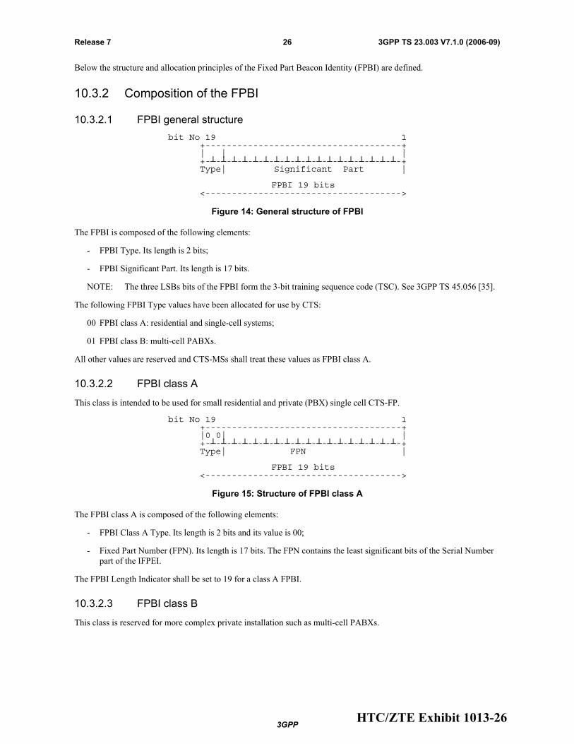
10.3.2.1 FPBI general structure
bit No 19 1 +-------------------------------------+ | | | +-┴-┴-┴-┴-┴-┴-┴-┴-┴-┴-┴-┴-┴-┴-┴-┴-┴-┴-+ Type| Significant Part |
FPBI 19 bits
<------------------------------------->
Figure 14: General structure of FPBI
The FPBI is composed of the following elements:
- FPBI Type. Its length is 2 bits;
- FPBI Significant Part. Its length is 17 bits.
NOTE: The three LSBs bits of the FPBI form the 3-bit training sequence code (TSC). See 3GPP TS 45.056 [35].
The following FPBI Type values have been allocated for use by CTS:
00 FPBI class A: residential and single-cell systems;
01 FPBI class B: multi-cell PABXs.
All other values are reserved and CTS-MSs shall treat these values as FPBI class A.
10.3.2.2 FPBI class A
This class is intended to be used for small residential and private (PBX) single cell CTS-FP.
bit No 19 1 +-------------------------------------+ |0 0| | +-┴-┴-┴-┴-┴-┴-┴-┴-┴-┴-┴-┴-┴-┴-┴-┴-┴-┴-+ Type| FPN |
FPBI 19 bits
<------------------------------------->
Figure 15: Structure of FPBI class A
The FPBI class A is composed of the following elements:
- FPBI Class A Type. Its length is 2 bits and its value is 00;
- Fixed Part Number (FPN). Its length is 17 bits. The FPN contains the least significant bits of the Serial Number part of the IFPEI.
The FPBI Length Indicator shall be set to 19 for a class A FPBI.
10.3.2.3 FPBI class B
This class is reserved for more complex private installation such as multi-cell PABXs.
HTC/ZTE Exhibit 1013-26

3GPP
3GPP TS 23.003 V7.1.0 (2006-09)27Release 7
bit No 19 1 +-------------------------------------+ |0 1| | +-┴-┴-┴-┴-┴-┴-┴-┴-┴-┴-┴-┴-┴-┴-┴-┴-┴-┴-+ Type| CNN + FPN + RPN |
FPBI 19 bits
<------------------------------------->
Figure 16: Structure of FPBI class B
The FPBI class B is composed of the following elements:
- FPBI Class B Type. Its length is 2 bits and its value is 01;
- CTS Network Number (CNN). Its length is defined by the manufacturer or the system installer;
- Fixed Part Number (FPN). Its length is defined by the manufacturer or the system installer;
- Radio Part Number (RPN) assigned by the CTS manufacturer or system installer. Its length is defined by the manufacturer or the system installer.
NOTE: RPN is used to separate a maximum of 2RPN length different cells from each other. This defines a cluster of cells supporting intercell handover. RPN length is submitted to a CTS-MS as a result of a successful attachment.
The FPBI Length Indicator shall be set to (2 + CNN Length) for a class B FPBI.
10.3.3 Allocation principles
The FPBI shall be allocated during the CTS-FP initialisation procedure. Any change to the value of the FPBI of a given CTS-FP shall be considered as a CTS-FP re-initialisation; i.e. each enrolled CTS-MS needs to be enrolled again.
FPBI are not required to be unique (i.e. several CTS-FP can have the same FPBI in different areas). Care should be taken to limit CTS-MS registration attempts to a fixed part with the same FPBI as another fixed part.
10.4 International Fixed Part Equipment Identity
10.4.1 General
The structure and allocation principles of the International Fixed Part Equipment Identity (IFPEI) are defined below.
10.4.2 Composition of the IFPEI
6 digits 2d 6 digits 2d <-----------><---><-----------><---> +-----------++---++-----------++---+ | || || || | +-┴-┴-┴-┴-┴-++-┴-++-┴-┴-┴-┴-┴-++-┴-+ TAC FAC SNR SVN
IFPEI 16 digits
<──────────────────────────────────>
Figure 17: Structure of IFPEI
The IFPEI is composed of the following elements (each element shall consist of decimal digits only):
- Type Approval Code (TAC). Its length is 6 decimal digits;
- Final Assembly Code (FAC). Its length is 2 decimal digits;
- Serial NumbeR (SNR). Its length is 6 decimal digits;
HTC/ZTE Exhibit 1013-27

3GPP
3GPP TS 23.003 V7.1.0 (2006-09)28Release 7
- Software Version Number (SVN) identifies the software version number of the fixed part equipment. Its length is 2 digits.
Regarding updates of the IFPEI: the TAC, FAC and SNR shall be physically protected against unauthorised change (see 3GPP TS 42.009 [36]); i.e. only the SVN part of the IFPEI can be modified.
10.4.3 Allocation principles
The Type Approval Code (TAC) is issued by a central body.
The place of final assembly (FAC) is encoded by the manufacturer.
Manufacturers shall allocate unique serial numbers (SNR) in a sequential order.
The Software Version Number (SVN) is allocated by the manufacturer after authorisation by the type approval authority. SVN value 99 is reserved for future use.
10.5 International Fixed Part Subscription Identity
10.5.1 General
The structure and allocation principles of the International Fixed Part Subscription Identity (IFPSI) are defined below.
10.5.2 Composition of the IFPSI
No more than 15 digits <------------------------------> 3d 3d | <-----><-----><------//--------> +-----++-----++------//--------+ | || || | +-┴-┴-++-┴-┴-++-┴-┴-┴//┴-┴-┴-┴-+ MCC CON FPIN |
NFPSI
<------------------------>
IFPSI <───────────────────────────────>
Figure 18: Structure of IFPSI
The IFPSI is composed of the following elements (each element shall consist of decimal digits only):
- Mobile Country Code (MCC) consisting of three digits. The MCC identifies the country of the CTS-FP subscriber (e.g. 208 for France);
- CTS Operator Number (CON). Its length is three digits;
- Fixed Part Identification Number (FPIN) identifying the CTS-FP subscriber.
The National Fixed Part Subscriber Identity (NFPSI) consists of the CTS Operator Number and the Fixed Part Identification Number.
10.5.3 Allocation principles
IFPSI shall consist of decimal characters (0 to 9) only.
The allocation of Mobile Country Codes (MCCs) is administered by the ITU-T.
The allocation of CTS Operator Number (CON) and the structure of National Fixed Part Subscriber Identity (NFPSI) are the responsibility of each National Regulation Authority.
CTS Operators shall allocate unique Fixed Part Identification Numbers.
HTC/ZTE Exhibit 1013-28

3GPP
3GPP TS 23.003 V7.1.0 (2006-09)29Release 7
11 Identification of Localised Service Area Cells may be grouped into specific localised service areas. Each localised service area is identified by a localised service area identity (LSA ID). No restrictions are placed on what cells may be grouped into a given localised service area.
The LSA ID can either be a PLMN significant number or a universal identity. This shall be known both in the networks and in the SIM.
The LSA ID consists of 24 bits, numbered from 0 to 23, with bit 0 being the LSB. Bit 0 indicates whether the LSA is a PLMN significant number or a universal LSA. If the bit is set to 0 the LSA is a PLMN significant number; if it is set to 1 it is a universal LSA.
The LSA ID shall be composed as shown in figure 19:
1 bit
LSA ID
23 bits
MSB LSB
Figure 19: Structure of LSA ID
12 Identification of PLMN, RNC, Service Area, CN domain and Shared Network Area
The following clauses describe identifiers which are used by both the CN and the UTRAN across the Iu interface. For identifiers which are solely used within the UTRAN, see 3GPP TS 25.401 [16].
NOTE: in the following subclauses, the double vertical bar notation || indicates the concatenation operator.
12.1 PLMN Identifier
A Public Land Mobile Network is uniquely identified by its PLMN identifier. PLMN-Id consists of Mobile Country Code (MCC) and Mobile Network Code (MNC).
- PLMN-Id = MCC || MNC
The MCC and MNC are predefined within a UTRAN, and set in the RNC via O&M.
12.2 CN Domain Identifier
A CN Domain Edge Node is identified within the UTRAN by its CN Domain Identifier. The CN Domain identifier is used over UTRAN interfaces to identify a particular CN Domain Edge Node for relocation purposes. The CN Domain identifier for Circuit Switching (CS) consists of the PLMN-Id and the LAC, whereas for Packet Switching (PS) it consists of the PLMN-Id, the LAC, and the RAC of the first accessed cell in the target RNS.
The two following CN Domain Identifiers are defined:
- CN CS Domain-Id = PLMN-Id || LAC
- CN PS Domain-Id = PLMN-Id || LAC || RAC
The LAC and RAC are defined by the operator, and set in the RNC via O&M.
HTC/ZTE Exhibit 1013-29
3GPP
3GPP TS 23.003 V7.1.0 (2006-09)30Release 7
For the syntax description and the use of this identifier in RANAP signalling, see 3GPP TS 25.413 [17].
12.3 CN Identifier
A CN node is uniquely identified within a PLMN by its CN Identifier (CN-Id). The CN-Id together with the PLMN identifier globally identifies the CN node. The CN-Id together with the PLMN-Id is used as the CN node identifier in RANAP signalling over the Iu interface.
Global CN-Id = PLMN-Id || CN-Id
The CN-Id is defined by the operator, and set in the nodes via O&M.
For the syntax description and the use of this identifier in RANAP signalling, see 3GPP TS 25.413 [17].
12.4 RNC Identifier
An RNC node is uniquely identified by its RNC Identifier (RNC-Id). The RNC-Id of an RNC is used in the UTRAN, in a GERAN which is operating in GERAN Iu mode and between them. A BSC which is part of a GERAN operating in Iu mode is uniquely identified by its RNC Identifier (RNC-Id). The RNC-Id of a BSC is used in a GERAN which is operating in GERAN Iu mode, in the UTRAN and between them. RNC-Id together with the PLMN identifier globally identifies the RNC. The RNC-Id on its own or the RNC-Id together with the PLMN-Id is used as the RNC identifier in the UTRAN Iub, Iur and Iu interfaces. The SRNC-Id is the RNC-Id of the SRNC. The C-RNC-Id is the RNC-Id of the controlling RNC. The D-RNC-Id is the RNC Id of the drift RNC.
- Global RNC-Id = PLMN-Id || RNC-Id
The RNC-Id is defined by the operator, and set in the RNC via O&M
For the syntax description and the use of this identifier in RANAP signalling, see 3GPP TS 25.413 [17].
For the usage of this identifier on Iur-g, see 3GPP TS 43.130 [43].
12.5 Service Area Identifier
The Service Area Identifier (SAI) is used to identify an area consisting of one or more cells belonging to the same Location Area. Such an area is called a Service Area and can be used for indicating the location of a UE to the CN.
The Service Area Code (SAC) together with the PLMN-Id and the LAC constitute the Service Area Identifier.
- SAI = PLMN-Id || LAC || SAC
The SAC is defined by the operator, and set in the RNC via O&M.
For the syntax description and the use of this identifier in RANAP signalling, see 3GPP TS 25.413 [17]. 3GPP TS 25.423 [37] and 3GPP TS 25.419 [38] define the use of this identifier in RNSAP and SABP signalling.
A cell may belong to one or two Service Areas. If it belongs to two Service Areas, one is applicable in the Broadcast (BC) domain and the other is applicable in both the CS and PS domains.
The Broadcast (BC) domain requires that its Service Areas each consist of only one cell. This does not limit the use of Service Areas for other domains. Refer to 3GPP TS 25.410 [39] for a definition of the BC domain.
12.6 Shared Network Area Identifier
The Shared Network Area Identifier (SNA-Id) is used to identify an area consisting of one or more Location Areas. Such an area is called a Shared Network Area and can be used to grant access rights to parts of a Shared Network to a UE in connected mode (see 3GPP TS 25.401 [39]).
The Shared Network Area Identifier consists of the PLMN-Id followed by the Shared Network Area Code (SNAC).
- SNA-Id = PLMN-Id || SNAC
HTC/ZTE Exhibit 1013-30

3GPP
3GPP TS 23.003 V7.1.0 (2006-09)31Release 7
The SNAC is defined by the operator.
For the syntax description and the use of this identifier in RANAP signalling, see 3GPP TS 25.413 [17].
13 Numbering, addressing and identification within the IP multimedia core network subsystem
13.1 Introduction
This clause describes the format of the parameters needed to access the IP multimedia core network subsystem. For further information on the use of the parameters see 3GPP TS 23.228 [24] and 3GPP TS 29.163 [63]. For more information on the ".3gppnetwork.org" domain name and its applicability, see Annex D of the present document. For more information on the ".invalid" top level domain see IETF RFC 2606 [64].
13.2 Home network domain name
The home network domain name shall be in the form of an Internet domain name, e.g. operator.com, as specified in IETF RFC 1035 [19].
If there is no ISIM application, the UE shall derive the home network domain name from the IMSI as described in the following steps:
1. take the first 5 or 6 digits, depending on whether a 2 or 3 digit MNC is used (see 3GPP TS 31.102 [27]) and separate them into MCC and MNC; if the MNC is 2 digits then a zero shall be added at the beginning;
2. use the MCC and MNC derived in step 1 to create the "mnc<MNC>.mcc<MCC>.3gppnetwork.org" domain name;
3. add the label "ims." to the beginning of the domain.
An example of a home network domain name is:
IMSI in use: 234150999999999;
Where:
MCC = 234;
MNC = 15;
MSIN = 0999999999,
Which gives the home network domain name: ims.mnc015.mcc234.3gppnetwork.org
13.3 Private user identity
The private user identity shall take the form of an NAI, and shall have the form username@realm as specified in clause 2.1 of IETF RFC 4282 [53].
NOTE: It is possible for a representation of the IMSI to be contained within the NAI for the private identity.
If there is no ISIM application, the private user identity is not known. If the private user identity is not known, the private user identity shall be derived from the IMSI.
The following steps show how to build the private user identity out of the IMSI:
1. use the whole string of digits as the username part of the private user identity;
2. convert the leading digits of the IMSI, i.e. MNC and MCC, into a domain name, as described in subclause 13.2.
HTC/ZTE Exhibit 1013-31

3GPP
3GPP TS 23.003 V7.1.0 (2006-09)32Release 7
The result will be a private user identity of the form "<IMSI>@ims.mnc<MNC>.mcc<MCC>.3gppnetwork.org". For example: If the IMSI is 234150999999999 (MCC = 234, MNC = 15), the private user identity then takes the form [email protected]
13.4 Public User Identity
The Public User Identity shall take the form of either a SIP URI (see IETF RFC 3261 [26]) or a tel URL (see IETF RFC 3966 [45]). A SIP URI for a Public User Identity shall take the form "sip:user@domain". SIP URI comparisions shall be performed as defined in IETF RFC 3261 [26], section 19.1.4.
If there is no ISIM application to host the public user identity, a temporary public user identity shall be derived, based on the IMSI. The temporary public user identity shall be of the form "user@domain" and shall therefore be equal to the private user identity. The private user identity is derived as described in subclause 13.2. That is, the private user identity will be appended to the string "sip:"
EXAMPLE: "sip:[email protected]".
13.5 Public service identity (PSI)
The public service identity shall take the form of either a SIP URI (see IETF RFC 3261 [26]) or a Tel URI (see IETF RFC 3966 [45]). A public service identity identifies a service, or a specific resource created for a service on an application server. The domain part is pre-defined by the IMS operators and the IMS system provides the flexibility to dynamically create the user part of the PSIs.
The PSIs are stored in the HSS either as a distinct PSI or as a wildcarded PSI. A distinct PSI contains the PSI that is used in routing , whilst a wildcarded PSI represents a collection of PSIs. Wildcarded PSIs enable optimisation of the operation and maintenance of the nodes. A wildcarded PSI consists of a delimited regular expression located either in the userinfo portion of the SIP URI or in the telephone-subscriber portion of the Tel URI. The regular expression in the wildcarded PSI shall take the form of Extended Regular Expressions (ERE) as defined in chapter 9 in IEEE 1003.1-2004 Part 1 [60]. The delimiter shall be the exclamation mark character ("!").
When stored in the HSS, the wildcarded PSI shall include the delimiter character to indicate the extent of the part of the PSI that is wildcarded. It is used to separate the regular expression from the fixed part of the wildcarded PSI.
Example: The following PSI could be stored in the HSS - "sip:chatlist!.*[email protected]".
When used on an interface, the PSI may include the delimiter character. The inclusion of the delimiter character within the PSI may allow the HSS to perform the matching of the PSI with the wildcarded PSIs stored in the HSS more rapidly and hence process messages faster (this potential optimisation is dependent upon HSS implementation). However, if the delimiter character is not included in the PSI in the interface message, the matching of the PSI to the PSIs stored in the HSS shall still be completed.
Example: The following PSIs communicated in interface messages to the HSS will match to the wildcarded PSI of "sip:chatlist!.*[email protected]" stored in the HSS:
13.6 Anonymous User Identity
The Anonymous User Identity shall take the form of a SIP URI (see IETF RFC 3261 [26]). A SIP URI for an Anonymous User Identity shall take the form "sip:user@domain". The user part shall be the string "anonymous" and the domain part shall be the string "anonymous.invalid". The full SIP URI for Anonymous User Identity is thus:
"sip:[email protected]"
HTC/ZTE Exhibit 1013-32

3GPP
3GPP TS 23.003 V7.1.0 (2006-09)33Release 7
For more information on the Anonymous User Identity and when it is used, see 3GPP TS 29.163 [63].
14 Numbering, addressing and identification for 3GPP System to WLAN Interworking
14.1 Introduction
This clause describes the format of the parameters needed to access the 3GPP system supporting the WLAN interworking. For further information on the use of the parameters see 3GPP TS 24.234 [48]. For more information on the ".3gppnetwork.org" domain name and its applicability, see Annex D of the present document.
14.2 Home network realm
The home network realm shall be in the form of an Internet domain name, e.g. operator.com, as specified in RFC 1035 [19].
When attempting to authenticate within WLAN access, the WLAN UE shall derive the home network domain name from the IMSI as described in the following steps:
1. take the first 5 or 6 digits, depending on whether a 2 or 3 digit MNC is used (see 3GPP TS 31.102 [27]) and separate them into MCC and MNC; if the MNC is 2 digits then a zero shall be added at the beginning;
2. use the MCC and MNC derived in step 1 to create the "mnc<MNC>.mcc<MCC>. 3gppnetwork.org" domain name;
3. add the label "wlan." to the beginning of the domain name.
An example of a WLAN NAI realm is:
IMSI in use: 234150999999999;
Where:
MCC = 234;
MNC = 15;
MSIN = 0999999999
Which gives the home network domain name: wlan.mnc015.mcc234.3gppnetwork.org.
14.3 Root NAI
The Root NAI shall take the form of a NAI, and shall have the form username@realm as specified in clause 2.1 of IETF RFC 4282 [53].
The username part format of the Root NAI shall comply with IETF RFC 4187 [50] when EAP AKA authentication is used and with IETF RFC 4186 [51], when EAP SIM authentication is used.
When the username part includes the IMSI, the Root NAI shall be built according to the following steps:
1. Generate an identity conforming to NAI format from IMSI as defined in EAP SIM [51] and EAP AKA [50] as appropriate;
2. Convert the leading digits of the IMSI, i.e. MNC and MCC, into a domain name, as described in subclause 14.2.
The result will be a root NAI of the form:
"0<IMSI>@wlan.mnc<MNC>.mcc<MCC>.3gppnetwork.org", for EAP AKA authentication and "1<IMSI>@wlan.mnc<MNC>.mcc<MCC>.3gppnetwork.org", for EAP SIM authentication
HTC/ZTE Exhibit 1013-33

3GPP
3GPP TS 23.003 V7.1.0 (2006-09)34Release 7
For example, for EAP AKA authentication: If the IMSI is 234150999999999 (MCC = 234, MNC = 15), the root NAI then takes the form [email protected].
14.4 Decorated NAI
The Decorated NAI shall take the form of a NAI and shall have the form 'homerealm!username@otherrealm' as specified in clause 2.7 of the IETF RFC 4282 [53].
The realm part of Decorated NAI consists of 'otherrealm', see the IETF draft 2486-bisRFC 4282 [53]. 'Homerealm' is the realm as specified in clause 14.2, using the HPLMN ID ('homeMCC' + 'homeMNC)'. 'Otherrealm' is the realm built using the PLMN ID (visitedMCC + visited MNC) of the PLMN selected as a result of WLAN PLMN selection (see 3GPP TS 24.234 [48]).
The username part format of the Root NAI shall comply with IETF RFC 4187 [50] when EAP AKA authentication is used and with IETF RFC 4186 [51], when EAP SIM authentication is used.
When the username part of Decorated NAI includes the IMSI, it shall be built following the same steps specified for Root NAI in clause 14.3.
The result will be a decorated NAI of the form:
"wlan.mnc<homeMNC>.mcc<homeMCC>.3gppnetwork.org !0<IMSI>@wlan.mnc<visitedMNC>.mcc<visitedMCC>.3gppnetwork.org", for EAP AKA authentication and " wlan.mnc<homeMNC>.mcc<homeMCC>.3gppnetwork.org !1<IMSI>@wlan.mnc<visitedMNC>.mcc<visitedMCC>.3gppnetwork.org ", for EAP SIM authentication
For example, for EAP AKA authentication: If the IMSI is 234150999999999 (MCC = 234, MNC = 15) and the PLMN ID of the Selected PLMN is MCC = 610, MNC = 71 then the Decorated NAI takes the form wlan.mnc015.mcc234.3gppnetwork.org!0234150999999999@wlan.mnc071.mcc610.3gppnetwork.org.
NOTE: the 'otherrealm' specified in the present document is resolved by the WLAN AN. If the WLAN AN does not have access to the GRX, then the WLAN AN should resolve the realm by other means e.g. static look-up table, private local DNS server acting as an authoritative name server for that sub-domain.
14.4A Fast Re-authentication NAI
The Fast Re-authentication NAI in both EAP-SIM and EAP-AKA shall take the form of a NAI as specified in clause 2.1 of IETF RFC 4282 [53]. If the 3GPP AAA server does not return a complete NAI, the Fast Re-authentication NAI shall consist of the username part of the fast re-authentication identity as returned from the 3GPP AAA server and the same realm as used in the permanent user identity. If the 3GPP AAA server returns a complete NAI as the re-authentication identity, then this NAI shall be used. The username part of the fast re-authentication identity shall be decorated as described in 14.4 if the Selected PLMN is different from the HPLMN.
NOTE: The permanent user identity is either the root or decorated NAI as defined in clauses 14.3 and 14.4.
EXAMPLE 1: If the fast re-authentication identity returned by the 3GPP AAA Server is 358405627015 and the IMSI is 234150999999999 (MCC = 234, MNC = 15), the Fast Re-authentication NAI for the case when NAI decoration is not used takes the form: [email protected]
EXAMPLE 2: If the fast re-authentication identity returned by the 3GPP AAA Server is "[email protected]" and the IMSI is 234150999999999 (MCC = 234, MNC = 15), the Fast Re-authentication NAI for the case when NAI decoration is not used takes the form: [email protected]
EXAMPLE 3: If the fast re-authentication identity returned by the 3GPP AAA Server is 358405627015 and the IMSI is 234150999999999 (MCC = 234, MNC = 15), and the PLMN ID of the Selected PLMN is MCC = 610, MNC = 71, the Fast Re-authentication NAI takes the form: wlan.mnc015.mcc234.3gppnetwork.org [email protected]
HTC/ZTE Exhibit 1013-34

3GPP
3GPP TS 23.003 V7.1.0 (2006-09)35Release 7
14.5 Temporary identities
The Temporary identities (Pseudonyms and re-authentication identities) shall take the form of a NAI username as specified in clause 2.1 of the IETF RFC 4282 [53].
Temporary identity shall be generated as specified in subclause 6.4.1 of 3GPP TS 33.234 [55]. This part of the temporary identity shall follow the UTF-8 transformation format specified in IETF RFC 2279 [54] except for the following reserved hexadecimal octet value:
FF.
When the temporary identity username is coded with FF, this reserved value is used to indicate the special case when no valid temporary identity exists in the WLAN UE (see 3GPP TS 24.234 [48]). The network shall not allocate a temporary identity with the whole username coded with the reserved hexadecimal value FF.
14.6 Alternative NAI
The Alternative NAI shall take the form of a NAI, i.e. 'any_username@REALM' as specified of IETF RFC 4282 [53]. The Alternative NAI shall not be routable from any AAA server.
The Alternative NAI shall contain a username part which is not derived from the IMSI. The username part shall not be a null string.
The REALM part of the NAI shall be “unreachable.3gppnetwork.org”.
The result shall be an NAI in the form of:
"<any_non_null_string>@unreachable.3gppnetwork.org"
14.7 W-APN
The W-APN is composed of two parts as follows:
- The W-APN Network Identifier; this defines to which external network the PDG is connected.
- The W-APN Operator Identifier; this defines in which PLMN the PDG serving the W-APN is located.
The W-APN Operator Identifier is placed after the W-APN Network Identifier. The W-APN consisting of both the Network Identifier and Operator Identifier corresponds to a FQDN of a PDG; the W-APN has, after encoding as defined in the paragraph below, a maximum length of 100 octets.
The encoding of the W-APN shall follow the Name Syntax defined in IETF RFC 2181 [18], IETF RFC 1035 [19] and IETF RFC 1123 [20]. The W-APN consists of one or more labels. Each label is coded as a one octet length field followed by that number of octets coded as 8 bit ASCII characters. Following IETF RFC 1035 [19] the labels shall consist only of the alphabetic characters (A-Z and a-z), digits (0-9) and the hyphen (-). Following IETF RFC 1123 [20], the label shall begin and end with either an alphabetic character or a digit. The case of alphabetic characters is not significant. The W-APN is not terminated by a length byte of zero.
For the purpose of presentation, a W-APN is usually displayed as a string in which the labels are separated by dots (e.g. "Label1.Label2.Label3").
14.7.1 Format of W-APN Network Identifier
The W-APN Network Identifier follows the format defined for APNs in subclause 9.1.1. In addition to what has been defined in subclause 9.1.1 the W-APN Network Identifier shall not end in ".3gppnetwork.org".
A W-APN Network Identifier may be used to access a service associated with a PDG. This may be achieved by defining:
HTC/ZTE Exhibit 1013-35

3GPP
3GPP TS 23.003 V7.1.0 (2006-09)36Release 7
- a W-APN which corresponds to a FQDN of a PDG, and which is locally interpreted by the PDG as a request for a specific service, or
- a W-APN Network Identifier consisting of 3 or more labels and starting with a Reserved Service Label, or a W-APN Network Identifier consisting of a Reserved Service Label alone, which indicates a PDG by the nature of the requested service. Reserved Service Labels and the corresponding services they stand for shall be agreed between operators who have WLAN roaming agreements.
14.7.2 Format of W-APN Operator Identifier
The W-APN Operator Identifier is composed of four labels. The last label shall be "pub.3gppnetwork.org". The second and third labels together shall uniquely identify the PLMN. The first label distinguishes the domain name as a W-APN.
For each operator, there is a default W-APN Operator Identifier (i.e. domain name). This default W-APN Operator Identifier is derived from the IMSI as follows:
"w-apn.mnc<MNC>.mcc<MCC>.pub.3gppnetwork.org"
where:
"mnc" and "mcc" serve as invariable identifiers for the following digits.
<MNC> and <MCC> are derived from the components of the IMSI defined in subclause 2.2.
Alternatively, the default W-APN Operator Identifier is derived using the MNC and MCC of the VPLMN. See 3GPP TS 24.234 [48] for more information.
The default W-APN Operator Identifier is used in both non-roaming and roaming situations when attempting to translate a W-APN consisting only of a Network Identifier into the IP address of the PDG in the HPLMN.
In order to guarantee inter-PLMN DNS translation, the <MNC> and <MCC> coding used in the "w-apn.mnc<MNC>.mcc<MCC>.pub.3gppnetwork.org" format of the W-APN OI shall be:
- <MNC> = 3 digits
- <MCC> = 3 digits
If there are only 2 significant digits in the MNC, one "0" digit shall be inserted at the left side to fill the 3 digits coding of MNC in the W-APN OI.
As an example, the W-APN OI for MCC 345 and MNC 12 is coded in the DNS as:
"w-apn.mnc012.mcc345.pub.3gppnetwork.org".
14.7.3 Alternative Format of W-APN Operator Identifier
For situations when the PDG serving the W-APN is located in such network that is not part of the GRX (i.e. the Interoperator IP backbone), the default Operator Identifier described in sub-clause 14.7.2 is not available for use. This restriction originates from the “.3gppnetwork.org” domain, which is only available in GRX DNS for actual use. Thus an alternative format of W-APN Operator Identifier is required for this case.
The Alternative W-APN Operator Identifiers shall be constructed as follows:
"w-apn.<valid operator’s REALM>"
where:
<valid operator’s REALM> corresponds to REALM names owned by the operator hosting the PDG serving the desired W-APN.
REALM names are required to be unique, and are piggybacked on the administration of the Public Internet DNS namespace. REALM names may also belong to the operator of the VPLMN.
HTC/ZTE Exhibit 1013-36

3GPP
3GPP TS 23.003 V7.1.0 (2006-09)37Release 7
As an example, the W-APN OI for the Operator REALM "notareal.com" is coded in the Public Internet DNS as:
"w-apn.notareal.com".
15 Identification of Multimedia Broadcast/Multicast Service
15.1 Introduction
This clause describes the format of the parameters needed to access the Multimedia Broadcast/Multicast service. For further information on the use of the parameters see 3GPP TS 23.246 [52].
15.2 Structure of TMGI
Temporary Mobile Group Identity (TMGI) is used within MBMS to uniquely identify Multicast and Broadcast bearer services..
The TMGI is composed of three parts:
1) MBMS Service ID consisting of three octets. MBMS Service ID uniquely identifies an MBMS bearer service within a PLMN.
2) Mobile Country Code (MCC) consisting of three digits. The MCC identifies uniquely the country of domicile of the BM-SC;
3) Mobile Network Code (MNC) consisting of two or three digits. The MNC identifies the PLMN which the BM-SC belongs to. The length of the MNC (two or three digits) depends on the value of the MCC.
For more information on the use of the TMGI, see 3GPP TS 23.246 [52].
15.3 Structure of MBMS SAI
The MBMS Service Area (MBMS SA) is defined in 3GPP TS 23.246 [52]. It comprises of one or more MBMS Service Area Identities (MBMS SAIs), in any case each MBMS SA shall not include more than 256 MBMS SAIs. An MBMS SAI shall identify a group of cells within a PLMN, that is independent of the associated Location/Routing/Service Area and the physical location of the cell(s). A cell shall be able to belong to one or more MBMS SAs, and therefore is addressable by one or more MBMS SAIs.
The MBMS SAI shall be a decimal number between 0 and 65,535 (inclusive). The value 0 shall have special meaning; it denotes the whole PLMN as the MBMS Service Area and it shall indicate to a receiving RNC/BSS that all cells reachable by that RNC/BSS are part of the MBMS Service Area.
With the exception of the specific MBMS Service Ares Identity with value 0, the MBMS Service Area Identity shall be unique within a PLMN and shall be defined in such a way that all the corresponding cells are MBMS capable.
16 Numbering, addressing and identification within the GAA subsystem
16.1 Introduction
This clause describes the format of the parameters needed to access the GAA system. For further information on the use of the parameters see 3GPP TS 33.221 [58]. For more information on the ".3gppnetwork.org" domain name and its applicability, see Annex D of the present document.
HTC/ZTE Exhibit 1013-37

3GPP
3GPP TS 23.003 V7.1.0 (2006-09)38Release 7
16.2 BSF address
The Bootstrapping Server Function (BSF) address is in the form of a Fully Qualified Domain Name as defined in IETF RFC 1035 [19]. The UE shall discover the BSF address from the identity information related to the UICC application that is used during the bootstrapping procedure i.e. IMSI for USIM, or IMPI for ISIM, in the following way:
- In the case where the USIM is used in bootstrapping, the BSF address shall be derived as follows:
1. take the first 5 or 6 digits, depending on whether a 2 or 3 digit MNC is used (see 3GPP TS 31.102 [27]) and separate them into MCC and MNC; if the MNC is 2 digits then a zero shall be added at the beginning;
2. use the MCC and MNC derived in step 1 to create the "mnc<MNC>.mcc<MCC>.pub.3gppnetwork.org" domain name;
3. add the label "bsf." to the beginning of the domain.
Example 1: If IMSI in use is "234150999999999", where MCC=234, MNC=15, and MSIN=0999999999, the BSF address would be "bsf.mnc015.mcc234.pub.3gppnetwork.org".
- In the case where ISIM is used in bootstrapping, the BSF address shall be derived as follows:
1. extract the domain name from the IMPI;
2. add the label "bsf." to the beginning of the domain.
Example 2: If the IMPI in use is "[email protected]", the BSF address would be "bsf.operator.com ".
NOTE: If the domain name in the IMPI configured in the ISIM is a sub-domain of "mnc<MNC>.mcc<MCC>.3gppnetwork.org" then a BSF address derived from such an IMPI will not be reachable! Operators are therefore warned to avoid using this domain name and sub-domains thereof as a domain name in the IMPI if GBA/GAA is to be configured in their UEs to use the ISIM.
17 Numbering, addressing and identification within the Generic Access Network
17.1 Introduction
This clause describes the format of the parameters needed to access the Generic Access Network (GAN). For further information on the use of the parameters and GAN in general, see 3GPP TS 43.318 [61] and 3GPP TS 44.318 [62]. For more information on the ".3gppnetwork.org" domain name and its applicability, see Annex D of the present document.
17.2 Network Access Identifiers
17.2.1 Home network realm
The home network realm shall be in the form of an Internet domain name, e.g. operator.com, as specified in IETF RFC 1035 [19].
The UE shall derive the home network realm from the IMSI as described in the following steps:
1. take the first 5 or 6 digits, depending on whether a 2 or 3 digit MNC is used (see 3GPP TS 31.102 [27]) and separate them into MCC and MNC; if the MNC is 2 digits then a zero shall be added at the beginning;
2. use the MCC and MNC derived in step 1 to create the "mnc<MNC>.mcc<MCC>.3gppnetwork.org" network realm;
3. add the label "gan." to the beginning of the network realm.
HTC/ZTE Exhibit 1013-38
3GPP
3GPP TS 23.003 V7.1.0 (2006-09)39Release 7
An example of a home network realm is:
IMSI in use: 234150999999999;
Where:
MCC = 234;
MNC = 15;
MSIN = 0999999999,
Which gives the home network realm: gan.mnc015.mcc234.3gppnetwork.org
17.2.2 Full Authentication NAI
The Full Authentication NAI in both EAP-SIM and EAP-AKA shall take the form of an NAI as specified in clause 2.1 of IETF RFC 4282 [53]. The format of the Full Authentication NAI shall comply with IETF RFC 4187 [50] when EAP-AKA authentication is used and with IETF RFC 4186 [51], when EAP-SIM authentication is used. The realm used shall be a home network realm as defined in sub-clause 17.2.1.
The result will therefore be an identity of the form:
"0<IMSI>@gan.mnc<MNC>.mcc<MCC>.3gppnetwork.org", for EAP-AKA authentication and "1<IMSI>@gan.mnc<MNC>.mcc<MCC>.3gppnetwork.org", for EAP-SIM authentication
EXAMPLE 1: For EAP AKA authentication: If the IMSI is 234150999999999 (MCC = 234, MNC = 15), the Full Authentication NAI takes the form [email protected].
EXAMPLE 2: For EAP SIM authentication: If the IMSI is 234150999999999 (MCC = 234, MNC = 15), the Full Authentication NAI takes the form [email protected].
17.2.3 Fast Re-authentication NAI
The Fast Re-authentication NAI in both EAP-SIM and EAP-AKA shall take the form of an NAI as specified in clause 2.1 of IETF RFC 4282 [53]. The UE shall use the re-authentication identity received during the previous EAP-SIM or EAP-AKA authentication procedure. If such an NAI contains a realm part then the UE should not modify it, otherwise it shall use a home network realm as defined in sub clause 17.2.1.
The result will therefore be an identity of the form:
"<re-authentication_ID_username>@<re-authentication_ID_realm> for both EAP-SIM and EAP-AKA authentication when a realm is present in the re-authentication identity received during the previous EAP-SIM or EAP-AKA authentication procedure and
"<re-authentication_ID_username>@gan.mnc<MNC>.mcc<MCC>.3gppnetwork.org", for both EAP-SIM and EAP-AKA authentication when a realm is not present in the re-authentication identity received during the previous EAP-SIM or EAP-AKA authentication procedure.
EXAMPLE 1: If the re-authentication identity is "12345" and the IMSI is 234150999999999 (MCC = 234, MNC = 15), the Fast Re-authentication NAI takes the form [email protected]
EXAMPLE 2: If the re-authentication identity is "[email protected]", the Fast Re-authentication NAI takes the form [email protected]
17.3 Node Identifiers
17.3.1 Home network domain name
The home network domain name shall be in the form of an Internet domain name, e.g. operator.com, as specified in IETF RFC 1035 [19].
HTC/ZTE Exhibit 1013-39

3GPP
3GPP TS 23.003 V7.1.0 (2006-09)40Release 7
The UE shall derive the home network domain name from the IMSI as described in the following steps:
1. take the first 5 or 6 digits, depending on whether a 2 or 3 digit MNC is used (see 3GPP TS 31.102 [27]) and separate them into MCC and MNC; if the MNC is 2 digits then a zero shall be added at the beginning;
2. use the MCC and MNC derived in step 1 to create the "mnc<MNC>.mcc<MCC>.pub.3gppnetwork.org" domain name;
3. add the label "gan." to the beginning of the domain name.
An example of a home network domain name is:
IMSI in use: 234150999999999;
Where:
MCC = 234;
MNC = 15;
MSIN = 0999999999,
Which gives the home network domain name: gan.mnc015.mcc234.pub.3gppnetwork.org
17.3.2 Provisioning GANC-SEGW identifier
The Provisioning GANC-SEGW identifier shall take the form of a fully qualified domain name (FQDN) as specified in IETF RFC 1035 [19]. If the (U)SIM is not provisioned with the FQDN or IP address of the Provisioning GANC-SEGW, the UE derives an FQDN from the IMSI to identify the Provisioning GANC-SEGW. The UE shall derive such an FQDN as follows:
1. create a domain name as specified in 17.3.1;
2. add the label "psegw." to the beginning of the domain name.
An example of an FQDN for a Provisioning GANC-SEGW is:
IMSI in use: 234150999999999;
Where:
MCC = 234;
MNC = 15;
MSIN = 0999999999,
Which gives the FQDN: psegw.gan.mnc015.mcc234.pub.3gppnetwork.org
17.3.3 Provisioning GANC identifier
The Provisioning GANC identifier shall take the form of a fully qualified domain name (FQDN) as specified in IETF RFC 1035 [19]. If the (U)SIM is not provisioned with the FQDN or IP address of the Provisioning GANC, the UE derives an FQDN from the IMSI to identify the Provisioning GANC. The UE shall derive such an FQDN as follows:
1. create a domain name as specified in 17.3.1;
2. add the label "pganc." to the beginning of the domain name.
An example of an FQDN for a Provisioning GANC is:
IMSI in use: 234150999999999;
Where:
MCC = 234;
HTC/ZTE Exhibit 1013-40

3GPP
3GPP TS 23.003 V7.1.0 (2006-09)41Release 7
MNC = 15;
MSIN = 0999999999,
Which gives the FQDN: pganc.gan.mnc015.mcc234.pub.3gppnetwork.org
HTC/ZTE Exhibit 1013-41
3GPP
3GPP TS 23.003 V7.1.0 (2006-09)42Release 7
Annex A (informative): Colour Codes
A.1 Utilization of the BSIC A BSIC is allocated to each cell. A BSIC can take one of 64 values. In each cell the BSIC is broadcast in each burst sent on the SCH, and is then known by all MSs which synchronise with this cell. The BSIC is used by the MS for several purposes, all aiming at avoiding ambiguity or interference which can arise when an MS in a given position can receive signals from two cells using the same BCCH frequency.
Some of the uses of the BSIC relate to cases where the MS is attached to one of the cells. Other uses relate to cases where the MS is attached to a third cell, usually somewhere between the two cells in question.
The first category of uses includes:
- The three least significant bits of the BSIC indicate which of the 8 training sequences is used in the bursts sent on the downlink common channels of the cell. Different training sequences allow for a better transmission if there is interference. The group of the three least significant bits of the BSIC is called the BCC (Base station Colour Code).
- The BSIC is used to modify the bursts sent by the MSs on the access bursts. This aims to avoid one cell correctly decoding access bursts sent to another cell.
The second category of uses includes:
- When in connected mode, the MSs measure and report the level they receive on a number of frequencies, corresponding to the BCCH frequencies of neighbouring cells in the same network as the used cell. Along with the measurement result, the MS sends to the network the BSIC which it has received on that frequency. This enables the network to discriminate between several cells which happen to use the same BCCH frequency. Poor discrimination might result in faulty handovers.
- The content of the measurement report messages is limited to information for 6 neighbour cells. It is therefore useful to limit the reported cells to those to which handovers are accepted. For this purpose, each cell provides a list of the values of the three most significant bits of the BSICs which are allocated to the cells which are useful to consider for handovers (usually excluding cells in other PLMNs). This information enables the MS to discard information for cells with non-conformant BSICs and not to report them. The group of the three most significant bits of the BSIC is called the NCC (Network Colour Code).
It should be noted that when in idle mode, the MS identifies a cell (for cell selection purposes) according to the cell identity broadcast on the BCCH and not by the BSIC.
A.2 Guidance for planning From these uses, the following planning rule can be derived:
If there exist places where MSs can receive signals from two cells, whether in the same PLMN or in different PLMNs, which use the same BCCH frequency, it is highly preferable that these two cells have different BSICs.
Where the coverage areas of two PLMNs overlap, the rule above is respected if:
1) The PLMNs use different sets of BCCH frequencies (In particular, this is the case if no frequency is common to the two PLMNs. This usually holds for PLMNs in the same country), or
2) The PLMNS use different sets of NCCs, or
3) BSIC and BCCH frequency planning is co-ordinated.
HTC/ZTE Exhibit 1013-42

3GPP
3GPP TS 23.003 V7.1.0 (2006-09)43Release 7
Recognizing that method 3) is more cumbersome than method 2), and that method 1) is too constraining, it is suggested that overlapping PLMNs which use a common part of the spectrum agree on different NCCs to be used in any overlapping areas. As an example, a preliminary NCC allocation for countries in the European region can be found in clause A.3 of this annex.
This example can be used as a basis for bilateral agreements. However, the use of the NCCs allocated in clause A.3 is not compulsory. PLMN operators can agree on different BSIC allocation rules in border areas. The use of BSICs is not constrained in non-overlapping areas, or if ambiguities are resolved by using different sets of BCCH frequencies.
A.3 Example of PLMN Colour Codes (NCCs) for the European region
Austria : 0 Belgium : 1 Cyprus : 3 Denmark : 1 Finland : 0 France : 0 Germany : 3 Greece : 0 Iceland : 0 Ireland : 3 Italy : 2 Liechtenstein : 2 Luxembourg : 2 Malta : 1 Monaco : 3 (possibly 0(=France)) Netherlands : 0 Norway : 3 Portugal : 3 San Marino : 0 (possibly 2(= Italy)) Spain : 1 Sweden : 2 Switzerland : 1 Turkey : 2 UK : 2 Vatican : 1 (possibly 2(=Italy) Yugoslavia : 3 This allows a second operator for each country by allocating the colour codes n (in the table) and n + 4. More than 2 colour codes per country may be used provided that in border areas only the values n and/or n+4 are used.
HTC/ZTE Exhibit 1013-43

3GPP
3GPP TS 23.003 V7.1.0 (2006-09)44Release 7
Annex B (normative): IMEI Check Digit computation
B.1 Representation of IMEI The International Mobile station Equipment Identity and Software Version number (IMEISV), as defined in clause 6, is a 16 digit decimal number composed of three distinct elements:
- an 8 digit Type Allocation Code (TAC);
- a 6 digit Serial Number (SNR); and
- a 2 digit Software Version Number (SVN).
The IMEISV is formed by concatenating these three elements as illustrated below:
TAC SNR SVN
Figure A.1: Composition of the IMEISV
The IMEI is complemented by a check digit as defined in clause 3. The Luhn Check Digit (CD) is computed on the 14 most significant digits of the IMEISV, that is on the value obtained by ignoring the SVN digits.
The method for computing the Luhn check is defined in Annex B of the International Standard "Identification cards - Numbering system and registration procedure for issuer identifiers" (ISO/IEC 7812 [3]).
In order to specify precisely how the CD is computed for the IMEI, it is necessary to label the individual digits of the IMEISV, excluding the SVN. This is done as follows:
The (14 most significant) digits of the IMEISV are labelled D14, D13 ... D1, where:
- TAC = D14, D13 ... D7 (with D7 the least significant digit of TAC);
- SNR = D6, D5 ... D1 (with D1 the least significant digit of SNR).
B.2 Computation of CD for an IMEI Computation of CD from the IMEI proceeds as follows:
Step 1: Double the values of the odd labelled digits D1, D3, D5 ... D13 of the IMEI.
Step 2: Add together the individual digits of all the seven numbers obtained in Step 1, and then add this sum to the sum of all the even labelled digits D2, D4, D6 ... D14 of the IMEI.
Step 3: If the number obtained in Step 2 ends in 0, then set CD to be 0. If the number obtained in Step 2 does not end in 0, then set CD to be that number subtracted from the next higher number which does end in 0.
B.3 Example of computation
IMEI (14 most significant digits):
TAC SNR D14 D13 D12 D11 D10 D9 D8 D7 D6 D5 D4 D3 D2 D1 2 6 0 5 3 1 7 9 3 1 1 3 8 3
HTC/ZTE Exhibit 1013-44

3GPP
3GPP TS 23.003 V7.1.0 (2006-09)45Release 7
Step 1:
2 6 0 5 3 1 7 9 3 1 1 3 8 3 x2 x2 x2 x2 x2 x2 x2 12 10 2 18 2 6 6
Step 2:
2 + 1 + 2 + 0 + 1 + 0 + 3 + 2 + 7 + 1 + 8 + 3 + 2 + 1 + 6 + 8 + 6 = 53
Step 3:
CD = 60 - 53 = 7
HTC/ZTE Exhibit 1013-45

3GPP
3GPP TS 23.003 V7.1.0 (2006-09)46Release 7
Annex C (normative): Naming convention This normative annex defines a naming convention which will make it possible for DNS servers to translate logical names for GSNs and RAs to physical IP addresses. The use of logical names is optional, but if the option is used, it shall comply with the naming convention described in this annex. The fully qualified domain names used throughout this annex shall follow the format defined in IETF RFC 1035 [19].
C.1 Routing Area Identities This subclause describes a possible way to support inter-PLMN roaming.
When an MS roams between two SGSNs within the same PLMN, the new SGSN finds the address of the old SGSN from the identity of the old RA. Thus, each SGSN can determine the address of every other SGSN in the PLMN.
When an MS roams from an SGSN in one PLMN to an SGSN in another PLMN, the new SGSN may be unable to determine the address of the old SGSN. Instead, the SGSN transforms the old RA information to a logical name of the form:
racAAAA.lacBBBB.mncYYY.mccZZZ.gprs
A and B shall be Hex coded digits; Y and Z shall be encoded as single digits (in the range 0-9).
If there are less than 4 significant digits in AAAA or BBBB, one or more "0" digit(s) is/are inserted at the left side to fill the 4 digit coding. If there are only 2 significant digits in YYY, a "0" digit is inserted at the left side to fill the 3 digit coding.
As an example, the logical name for RAC 123A, LAC 234B, MCC 167 and MNC 92 will be coded in the DNS server as: rac123A.lac234B.mnc092.mcc167.gprs.
The SGSN may then acquire the IP address of the old SGSN from a DNS server, using the logical address. Introducing the DNS concept in GPRS enables operators to use logical names instead of IP addresses when referring to nodes (e.g. GSNs), thus providing flexibility and transparency in addressing. Each PLMN should include at least one DNS server (which may optionally be connected via the DNS service provided by the GSM Association). Note that these DNS servers are GPRS internal entities, unknown outside the GPRS system.
The above implies that at least MCC || MNC || LAC || RAC (= RAI) is sent as the RA parameter over the radio interface when an MS roams to another RA.
If for any reason the new SGSN fails to obtain the address of the old SGSN, the new SGSN takes the same actions as when the corresponding event occurs within one PLMN.
Another way to support seamless inter-PLMN roaming is to store the SGSN IP addresses in the HLR and request them when necessary.
If Intra Domain Connection of RAN Nodes to Multiple CN Nodes (see 3GPP TS 23.236 [23]) is applied then the Network Resource Identifier (NRI) identifies uniquely a given SGSN node out of all the SGSNs serving the same pool area.
If the new SGSN is not able to extract the NRI from the old P-TMSI, it shall retrieve the address of the default SGSN (see 3GPP TS 23.236 [23]) serving the old RA, using the logical name described earlier in this section. The default SGSN in the old RA relays the GTP signalling to the old SGSN identified by the NRI in the old P-TMSI unless the default SGSN itself is the old SGSN.
If the new SGSN is able to extract the NRI from the old P-TMSI, then it shall attempt to derive the address of the old SGSN from the NRI and the old RAI. NRI-to-SGSN assignments may be either configured (by O&M) in the new SGSN, or retrieved from a DNS server. If a DNS server is used, it shall be queried using the following logical name, derived from the old RAI and NRI information:
HTC/ZTE Exhibit 1013-46

3GPP
3GPP TS 23.003 V7.1.0 (2006-09)47Release 7
nriCCCC.racDDDD.lacEEEE.mncYYY.mccZZZ.gprs
C, D and E shall be Hex coded digits, Y and Z shall be encoded as single digits (in the range 0-9). If there are less than 4 significant digits in CCCC, DDDD or EEEE, one or more "0" digit(s) is/are inserted at the left side to fill the 4 digit coding. If there are only 2 significant digits in YYY, a "0" digit is inserted at the left side to fill the 3 digits coding.
As an example, the logical name for NRI 3A, RAC 123A, LAC 234B, MCC 167 and MNC 92 will be coded in the DNS server as: nri003A.rac123A.lac234B.mnc092.mcc167.gprs.
If for any reason the new SGSN fails to obtain the address of the old SGSN using this method, then as a fallback method it shall retrieve the address of the default SGSN serving the old RA.
C.2 GPRS Support Nodes This subclause defines a naming convention for GSNs.
It shall be possible to refer to a GSN by a logical name which shall then be translated into a physical IP address. This clause proposes a GSN naming convention which would make it possible for an internal GPRS DNS server to make the translation.
An example of how a logical name of an SGSN could appear is: sgsnXXXX.mncYYY.mccZZZ.gprs
X, shall be Hex coded digits, Y andZz shall be encoded as single digits (in the range 0-9).
If there are less than 4 significant digits in XXXX one or more "0" digit(s) is/are inserted at the left side to fill the 4 digits coding. If there are only 2 significant digits in YYY, a "0" digit is inserted at the left side to fill the 3 digit coding.
As an example, the logical name for SGSN 1B34, MCC 167 and MNC 92 will be coded in the DNS server as: sgsn1B34. mnc092.mcc167.gprs
C.3 Target ID This subclause describes a possible way to support SRNS relocation.
In UMTS, when SRNS relocation is executed, a target ID which consists of MCC, MNC and RNC ID is used as routeing information to route to the target RNC via the new SGSN. An old SGSN shall resolve a new SGSN IP address by a target ID to send the Forward Relocation Request message to the new SGSN.
It shall be possible to refer to a target ID by a logical name which shall be translated into an SGSN IP address to take into account inter-PLMN handover. The old SGSN transforms the target ID information into a logical name of the form:
rncXXXX.mncYYY.mccZZZ.gprs
X shall be Hex coded digits; Y and Z shall be encoded as single digits (in the range 0-9). If there are less than 4 significant digits in XXXX, one or more "0" digit(s) is/are inserted at the left side to fill the 4 digits coding. If there are only 2 significant digits in YYY, a "0" digit is inserted at the left side to fill the 3 digit coding. Then, for example, a DNS server is used to translate the logical name to an SGSN IP address.
As an example, the logical name for RNC 1B34, MCC 167 and MNC 92 will be coded in the DNS server as: rnc1B34.mnc092.mcc167.gprs
HTC/ZTE Exhibit 1013-47

3GPP
3GPP TS 23.003 V7.1.0 (2006-09)48Release 7
Annex D (informative): Applicability and use of the ".3gppnetwork.org" domain name There currently exists a private IP network between operators to provide connectivity for user transparent services that utilise protocols that rely on IP. This includes (but is not necessarily limited to) such services as GPRS/PS roaming, WLAN roaming, GPRS/PS inter-PLMN handover and inter-MMSC MM delivery. This inter-PLMN IP backbone network consists of indirect connections using brokers (known as GRXs – GPRS Roaming Exchanges) and direct inter-PLMN connections (e.g. private wire); it is however not connected to the Internet. More details can be found in GSMA PRD IR.34 [57].
Within this inter-PLMN IP backbone network, the domain name ".gprs" was originally conceived as the only domain name to be used to enable DNS servers to translate logical names for network nodes to IP addresses (and vice versa). However, after feedback from the Internet Engineering Task Force (IETF) it was identified that use of this domain name has the following drawbacks:
1. Leakage of DNS requests for the ".gprs" top level domain into the public Internet is inevitable at sometime or other, especially as the number of services (and therefore number of nodes) using the inter-PLMN IP backbone increases. In the worst case scenario of faulty clients, the performance of the Internet's root DNS servers would be seriously degraded by having to process requests for a top level domain that does not exist.
2. It would be very difficult for network operators to detect if/when DNS requests for the ".gprs" domain were leaked to the public Internet (and therefore the security policies of the inter-PLMN IP backbone network were breached), because the Internet's root DNS servers would simply return an error message to the sender of the request only.
To address the above, the IETF recommended using a domain name that is routable in the pubic domain but which requests to it are not actually serviced in the public domain. The domain name ".3gppnetwork.org" was chosen as the new top level domain name to be used (as far as possible) within the inter-PLMN IP backbone network. Originally, only the DNS servers connected to the inter-PLMN IP backbone network were populated with the correct information needed to service requests for all sub-domains of this domain. However, it was later identified that some new services needed their allocated sub-domain(s) to be resolvable by the UE and not just network nodes. To address this, a new, higher-level sub-domain was created, "pub.3gppnetwork.org", to be used in all domain names that need to be resolvable by UEs (and possibly network nodes too).
Therefore, DNS requests sent to the local area networks (possibly connected to the Internet) for the "pub.3gppnetwork.org" domain name can be resolved, while requests for all other sub-domains of "3gppnetwork.org" can simply be configured to return the usual DNS error for unknown hosts (thereby avoiding potential extra load on the Internet's root DNS servers).
The GSM Association is in charge of allocating new sub-domains of the ".3gppnetwork.org" domain name. The procedure for requesting new sub-domains can be found in Annex E.
HTC/ZTE Exhibit 1013-48

3GPP
3GPP TS 23.003 V7.1.0 (2006-09)49Release 7
Annex E (normative): Procedure for sub-domain allocation When a 3GPP member company identifies the need for a new sub-domain name of ".3gppnetwork.org", that 3GPP member company shall propose a CR to this specification at the earliest available meeting of the responsible working group for this TS. The CR shall propose a new sub-domain name. The new sub-domain proposed shall be formatted in one of the formats as described in the following table.
Sub-domain Format Intended Usage <service_id>.mnc<MNC>.mcc<MCC>.3gppnetwork.org (see notes 1 and 2)
Domain name that is to be resolvable by network nodes only. This format inherently adds protection to the identified node, in that attempted DNS resolutions instigated directly from end user equipment will fail indefinitely.
<service_id>.mnc<MNC>.mcc<MCC>.pub.3gppnetwork.org (see notes 1 and 2)
Domain name that is to be resolvable by UEs and/or network nodes. This format inherently adds global resolution capability, but at the expense of confidentiality of network topology.
Table E.1: Sub-domain formats for the "3gppnetwork.org" domain and their respective intended usage
NOTE 1: "<service_ID>" is a chosen label, conformant to DNS naming conventions (usually IETF RFC 1035 [19] and IETF RFC 1123 [20]) that clearly and succinctly describe the service and/or operation that is intended to use this sub-domain.
NOTE 2: "<MNC>" and "<MCC>" are the MNC (padded to the left with a zero, if only a 2-digit MNC) and MCC of a PLMN.
Care should be taken when choosing which format a domain name should use. Once a format has been chosen, the responsible working group shall then check the CR and either endorse it or reject it. If the CR is endorsed, then the responsible working group shall send an LS to the GSMA IREG describing the following key points:
- the context
- the service
- intended use
- involved actors
- proposed new sub-domain name
GSMA IREG will then verify the consistence of the proposal and its usage within the domain’s structure and interworking rules (e.g. access to the GRX Root DNS servers). GSMA IREG will then endorse or reject the proposal and inform the responsible working group (in 3GPP). It is possible that GSMA IREG will also specify, changes to the newly proposed sub-domain name (e.g. due to requested sub-domain name already allocated).
It should be noted that services already defined to use the ".gprs" domain name will continue to do so and shall not use the new domain name of ".3gppnetwork.org"; this is to avoid destabilising services that are already live.
HTC/ZTE Exhibit 1013-49

3GPP
3GPP TS 23.003 V7.1.0 (2006-09)50Release 7
Annex F (informative): Change history
Change history
TSG CN# Spec Version CR <Phase> New Version Subject/Comment Apr 1999 GSM 03.03 7.0.0 Transferred to 3GPP CN1 CN#03 23.003 3.0.0 Approved at CN#03 CN#04 23.003 3.0.0 001 R99 3.1.0 Definition of escape PLMN code CN#04 23.003 3.0.0 002r1 R99 3.1.0 SSN reallocation for CAP, gsmSCF, SIWF, GGSN,
SGSN, CN#04 23.003 3.0.0 003 R99 3.1.0 Correction of VGC/VBC reference CN#04 23.003 3.0.0 004 R99 3.1.0 Harmonisation of the MNC-length; correction of CR
A019r1 CN#04 23.003 3.0.0 005 R99 3.1.0 Correction to the MNC length CN#05 23.003 3.1.3 007r1 R99 3.2.0 ASCII coding of <MNC> and <MCC> in APN OI CN#05 23.003 3.1.3 008 R99 3.2.0 New SSN allocation for RANAP and RNSAP CN#06 23.003 3.2.1 011 R99 3.3.0 Support of VLR and HLR Data Restoration
procedures with LCS CN#07 23.003 3.3.0 014 R99 3.4.0 Necessity of the function of the calculation of an
SGSN IP address from the target ID CN#07 23.003 3.3.0 016 R99 3.4.0 Definition of Service Area Identification CN#07 23.003 3.3.0 017r2 R99 3.4.0 Modification of clause 6.2 to enhance IMEI securityCN#07 23.003 3.3.0 018 R99 3.4.0 Coding of a deleted P-TMSI signature CN#07 23.003 3.4.0 013r2 R99 3.4.1 Introduction of Reserved Service Labels in the APNCN#08 23.003 3.4.1 019 R99 3.5.0 Missing UTRAN identifiers CN#08 23.003 3.4.1 021r1 R99 3.5.0 Editorial Modification of clause 6.2.2. CN#08 23.003 3.4.1 022 R99 3.5.0 IMEI Formats and Encoding CN#09 23.003 3.5.0 023 R99 3.6.0 Alignment of 23.003 with text from 25.401 CN#10 23.003 3.6.0 024 R99 3.7.0 Moving informative Annex A from 3G TS 29.060
and making it normative. CN#11 23.003 3.7.0 025 R99 3.8.0 Clarification to Definition of Service Area Identifier CN#11 23.003 3.7.0 026 R99 3.8.0 Forbidden APN network identifier labels CN#11 23.003 3.8.0 Rel-4 4.0.0 Updated from R99 to Rel-4 after CN#11 CN#12 23.003 4.0.0 028r1 Rel-4 4.1.0 Remove reference to TS23.022 CN#12 23.003 4.1.0 029r1 Rel-5 5.0.0 New Subsystem Number for the Position
Calculation Application Part on the Iupc interface CN#13 23.003 5.0.0 032 Rel-5 5.1.0 Clarification on APN labels that begin with a digit CN#13 23.003 5.0.0 Rel-5 5.1.0 Editorial clean up CN#14 23.003 5.1.0 033 Rel-5 5.2.0 Rules for TMSI partitioning CN#14 23.003 5.1.0 035 Rel-5 5.2.0 Introduction of Global CN-ID definition CN#16 23.003 5.2.0 037r1 Rel-5 5.3.0 IuFlex support for determining old SGSN during
handover/relocation CN#16 23.003 5.2.0 038 Rel-5 5.3.0 Allocation of unique prefixes to IPv6 terminals CN#16 23.003 5.2.0 041r2 Rel-5 5.3.0 Use of a temporary public user identity CN#16 23.003 5.2.0 044 Rel-5 5.3.0 Restructuring the IMEI to combine the TAC and
FAC CN#16 23.003 5.2.0 045 Rel-5 5.3.0 Use of the TLLI codespace in GERAN Iu mode CN#17 23.003 5.3.0 048r3 Rel-5 5.4.0 Clarification on the definition of DNS CN#17 23.003 5.3.0 050r1 Rel-5 5.4.0 Support for Shared Network in connected mode:
definition of SNA CN#17 23.003 5.3.0 053r1 Rel-5 5.4.0 Restructuring the IMEI to combine the TAC and
FAC in Annex B CN#17 23.003 5.3.0 054 Rel-5 5.4.0 SCCP sub-system Number for IM-SSF CN#18 23.003 5.4.0 055r1 Rel-5 5.5.0 Iur-g Introduction CN#18 23.003 5.4.0 056r2 Rel-5 5.5.0 Editorial clean-up CN#18 23.003 5.4.0 057 Rel-5 5.5.0 Correction of the private user identity's form CN#18 23.003 5.4.0 058 Rel-5 5.5.0 Addition of a reference to the ITU-T
RECOMMENDATION E.212 for Mobile Country Codes
CN#18 23.003 5.4.0 059 Rel-5 5.5.0 Correction to the form of public user identity
HTC/ZTE Exhibit 1013-50

3GPP
3GPP TS 23.003 V7.1.0 (2006-09)51Release 7
Change history
TSG CN# Spec Version CR <Phase> New Version Subject/Comment CN#18 23.003 5.4.0 062 Rel-5 5.5.0 Fix miss-interworking for LMSI handling (LMSI
definition) CN#18 23.003 5.5.0 Rel-5 5.5.1 Corrupted figures 13 – 18 fixed CN#20 23.003 5.5.1 065 Rel-5 5.6.0 Correction to Annex C.3 – Target ID CN#21 23.003 5.6.0 072 Rel-5 5.7.0 Correction to definition of Group-ID, Group call area
ID and Group Call Reference CN#21 23.003 5.7.0 073r2 Rel-6 6.0.0 PSI definition CN#22 23.003 6.0.0 078 Rel-6 6.1.0 On the length of the APN NI CN#23 23.003 6.1.0 081 Rel-6 6.2.0 Changes and corrections to DNS names CN#23 23.003 6.1.0 083r2 Rel-6 6.2.0 Changes to enable the GSMA root DNS
architecture using ".3gppnetwork.org" TLD CN#23 23.003 6.1.0 085r1 Rel-6 6.2.0 WLAN access parameters moved from TS 24.234
to TS 23.003 CN#23 23.003 6.1.0 087 Rel-6 6.2.0 Assignment of SSN for Presence Network Agent CN#24 23.003 6.2.0 086r4 Rel-6 6.3.0 Clarification of the uses of SIP URIs for Public User
ID CN#24 23.003 6.2.0 088r1 Rel-6 6.3.0 Addition of TMGI CN#25 23.003 6.3.0 089 Rel-6 6.4.0 Background of and procedures for the
".3gppnetwork.org" domain name CN#25 23.003 6.3.0 090r2 Rel-6 6.4.0 Decorated NAI format CN#25 23.003 6.3.0 091r1 Rel-6 6.4.0 Introduction of temporary identities CN#26 23.003 6.4.0 092r2 Rel-6 6.5.0 'otherrealm' format of Decorated NAI CN#26 23.003 6.4.0 095r1 Rel-6 6.5.0 Clarification of NRI position within (P)-TMSI CN#26 23.003 6.4.0 096r1 Rel-6 6.5.0 BSF address CN#27 23.003 6.5.0 097 Rel-6 6.6.0 Clarification of the TMGI CN#27 23.003 6.5.0 093r3 Rel-6 6.6.0 Definition of Alternative NAI CT#28 23.003 6.6.0 0099r4 Rel-6 6.7.0 W-APN Definition CT#28 23.003 6.6.0 0100r5 Rel-6 6.7.0 Correction to wildcards in PSI
6.7.0 Rel-6 6.7.1 2005-07: Correct line break before clause 14 header
CT#29 23.003 6.7.1 0102r2 Rel-6 6.8.0 Corrections to "3gppnetwork.org" addressing CT#29 23.003 6.7.1 0103 Rel-6 6.8.0 Addition of addressing for the Generic Access
Network CT#29 23.003 6.7.1 0104r1 Rel-6 6.8.0 PSI routing CT#31 23.003 6.8.0 0106r1 Rel-6 6.9.0 IETF references update CT#32 23.003 6.9.0 0107r1 Rel-6 6.10.0 Fast re-authentication identity clarification CT#32 23.003 6.9.0 0109r1 Rel-6 6.10.0 Case insensitive naming convention CT#32 23.003 6.9.0 0111r1 Rel-6 6.10.0 Correction to the W-APN definition CT#32 23.003 6.10.0 0112r1 Rel-7 7.0.0 Definition of Anonymous URI in IMS CT#33 23.003 7.0.0 0117r1 Rel-7 7.1.0 Re-authentication identity definition correction CT#33 23.003 7.0.0 0115r3 Rel-7 7.1.0 Definition of MBMS SAI
HTC/ZTE Exhibit 1013-51