Embed Size (px)
Citation preview

3GPP LTE Release 9 and 10 requirement analysis to physical layer UE
testing Tomi Johansson Helsinki September 4, 2013 UNIVERSITY OF HELSINKI Department of Computer Science

HELSINGIN YLIOPISTO − HELSINGFORS UNIVERSITET – UNIVERSITY OF HELSINKI Tiedekunta/Osasto − Fakultet/Sektion –Faculty/Section
Faculty of Science
Laitos − Institution − Department
Department of Computer Science Tekijä − Författare − Author
Tomi Johansson Työn nimi − Arbetets titel − Title
3GPP LTE Release 9 and 10 requirement analysis to physical layer UE testing Oppiaine − Läroämne − Subject
Computer Science Työn laji − Arbetets art − Level
M. Sc. Thesis Aika − Datum − Month and year
September 4, 2013 Sivumäärä − Sidoantal − Number of pages 114
Tiivistelmä − Referat − Abstract
The purpose of this thesis was to analyze the testing requirements to physical layer features which are used in LTE Release 9 and 10 timeframe. The aim of the analysis was to define test case requirements for new features from the physical layer point of view. This analysis can then be utilized to implement and design test cases using commercial eNB simulators. The analysis was carried out by studying the 3GPP specifications and by investigating the integration and system level testing requirements. Different feature specific parameters were evaluated and different testing aspects were studied in order to verify the functionalities and performance of the UE. Also, different conformance test case scenarios and field testing aspects were investigated in order to improve the test case planning in the integration and system testing phase. The analysis showed that in Rel-9 there are two main features which have a great impact on the Rel-9 physical layer testing. These two features are the dual-layer beamforming and UE positioning which is done with OTDOA and E-CID methods. It was analyzed that the requirements for the downlink dual-layer beamforming focus on TDD side and the test plan must contain especially throughput performance testing in integration and system phase testing. OTDOA and E-CID methods, on the other hand, need test plans which are concentrating on the positioning accuracy. In Rel-10, the analysis showed that there are plenty of new features on physical layer to ensure the transition from LTE to LTE-Advanced. The main requirements were assigned for the CA feature which has testing activities especially on the UE feedback operations. Also, different kinds of CA deployment scenarios were analyzed to evaluate more closely the initial CA testing scenarios in integration and system testing. Analysis continued with downlink multi-layer beamforming where the requirements were seen to concentrate on new CSI-RS aspects and to throughput performance testing. Uplink MIMO aspects were analyzed at the end and the studies showed that this feature may have a minor role in Rel-10 timeframe and therefore it does not have any important testing requirements which should be taken into account in test plans. ACM Computing Classification System (CCS): C.2.2 [Network Protocols], D.2.4 [Software/Program Verification], D.2.5 [Testing and Debugging]
Avainsanat – Nyckelord − Keywords
LTE, LTE-Advanced, 4G, E-UTRAN, LTE Release 9, LTE Release 10, PHY, testing Säilytyspaikka − Förvaringställe − Where deposited
Kumpula Science Library, serial number C- Muita tietoja − Övriga uppgifter − Additional information

Acknowledgement
This master´s thesis was done at Renesas Mobile Europe research and development site in Salo, Finland. I would like to thank my supervisors Pasi Järvinen, Juha Vasarainen, Ville Tiikasalo and all my colleagues for support and comments, especially Keijo Jo-hansson who pushed me to finalize this work.
I would like to express my gratitude also to my instructor Professor Sasu Tarkoma for the guidance throughout my work on this thesis.
Finally, I would like to give special thanks to my parents who have supported and moti-vated my studies.
Salo 28th of July 2013
Tomi Johansson
Abbreviation
3GPP Third Generation Partnership Project
ACK Positive Acknowledgement
A-GNSS Assisted Global Navigation Satellite System
AoA Angle of Arrival
AWGN Additive White Gaussian Noise
BLER Block Error Rate
CA Carrier Aggregation
CC Component Carrier
CDMA Code Division Multiple Access
CFI Control Format Indicator
CIF Carrier Indicator Field
CN Core Network
CoMP Coordinated Multipoint Transmission and Reception
CP Cyclic Prefix
CQI Channel Quality Indicator
C-RNTI Cell Radio Network Temporary Identifier
CS Circuit Switched
CSI Channel State Information
CSI-RS Channel State Information Reference Signal
CW Codeword
DCI Downlink Control Information
DM-RS Demodulation Reference Signal
DRX Discontinuous Reception
E-CID Enhanced Cell ID
eNB Evolved Node B
EPC Evolved Packet Core

EPS Evolved Packet System
E-SMLC Enhanced Serving Mobile Location Center
E-UTRA Evolved Universal Terrestrial Radio Access
E-UTRAN Evolved Universal Terrestrial Radio Access Network
FCC Federal Communications Commission
FDD Frequency Division Duplex
FFT Fast Fourier Transform
FGI Feature Group Indicator
GCF Global Certification Forum
GSM Global System for Mobile Communications
HARQ Hybrid-ARQ
HI HARQ Indicator
ICIC Inter-Cell Interference Coordination
IMT International Mobile Telecommunications
IO(D)T Inter Interoperability (Development) Testing
IP Internet Protocol
ISI Intersymbol Interference
ITU-R ITU Radiocommunication Sector
LCS Location Services
LPP LTE Positioning Protocol
LPPa LPP annex
LTE Long Term Evolution
LTE-A LTE-Advanced
MAC Medium Access Control
MCS Modulation and Coding Scheme
MIMO Multiple Input Multiple Output
MME/SAE GW Mobility Management Entity/SAE Gateway
MSC Mobile Switching Centre

MU-MIMO Multi User MIMO
NACK Negative Acknowledgement
NAS Non-Access Stratum
NDI New Data Indicator
OCC Orthogonal Cover Codes
OFDMA Orthogonal Frequency Division Multiple Access
OTDOA Observed Time Difference Of Arrival
PAPR Peak-to-Average Power Ratio
PBCH Physical Broadcast Channel
PCC Uplink Primary Component Carrier
PCell Primary Serving Cell
PCFICH Physical Control Format Indicator Channel
PDCCH Physical Downlink Control Channel
PDCP Packet Data Convergence Protocol
PDSCH Physical Downlink Shared Channel
P-GW Packet Data Network Gateway
PHICH Physical HARQ Indicator Channel
PHR Power Headroom Reports
PHY Physical Layer
PMI Precoding Matrix Indicator
PRACH Physical Random Access Channel
PRB Physical Resource Block
PRG Precoding Resource Block Groups
PRS Positioning Reference Signals
PTCRB PCS Type Certification Review Board
PTI Precoding Type Indicator
PUCCH Physical Uplink Control Channel
PUSCH Physical Uplink Shared Channel

R&TTE Radio and Telecommunications Terminal Equipment
RAN Radio Access Network
RAT Radio Access Technology
RE Resource elements
Rel-8 LTE Release 8
Rel-9 LTE Release 9
Rel-10 LTE Release 10
RF Radio Frequency
RI Rank Indicator
RLC Radio Link Control
RNC Radio Network Controller
RRC Radio Resource Control
RRM Radio Resource Management
RSRP Reference Signal Received Power
RSRQ Reference Signal Received Quality
RSTD Reference Signal Time Difference
RTT Round Trip Time
S/P Serial to Parallel
SAE System Architecture Evolution
SCC Downlink and Uplink Secondary Component Carrier
SCell Secondary Serving Cell
SC-FDMA Single Carrier Frequency Division Multiple Access
SCID Scrambling Identity
S-GW Serving Gateway
SIB2 System Information Block Type 2
SNR Signal to Noise Ratio
SR Scheduling Request
SRS Sounding Reference Signal
SU-MIMO Single User MIMO
TB Transport Block
TDD Time Division Duplex
TM Transmission Mode
TPC Transmission Power Control
UCI Uplink Control Information
UE User Equipment
UMTS Universal Mobile Telecommunications System
VoIP Voice-over IP
VRB Virtual Resource Block

Contents
1 INTRODUCTION .................................................................................................... 1
2 LTE – LONG TERM EVOLUTION ........................................................................ 3
2.1 Background ....................................................................................................... 3
2.2 Standardization .................................................................................................. 4
2.3 Requirements..................................................................................................... 5
2.4 LTE/SAE system architecture ........................................................................... 6
2.5 LTE radio access ............................................................................................... 8
2.5.1 OFDMA and SC-FDMA ................................................................... 8
2.5.2 MIMO ............................................................................................. 10
2.6 LTE radio protocol architecture and channels ................................................ 11
2.7 Physical layer general overview...................................................................... 13
2.7.1 Physical layer frame structure and resource elements .................... 13
2.7.2 Transmission schemes on physical layer ........................................ 15
2.7.3 Physical layer testing related procedures ........................................ 21
2.8 Physical layer in Release 9 and 10 .................................................................. 22
3 LTE FUNCTIONALITY AND PERFORMANCE TESTING .............................. 24
3.1 Overview of R&D UE testing ......................................................................... 24
3.2 Simulations of network operations and R&D testing ..................................... 25
3.3 Conformance and field testing ........................................................................ 27
3.4 UE certification ............................................................................................... 29
4 LTE RELEASE 9 ENHANCEMENTS AND CHALLENGES TOWARDS PHYSICAL LAYER UE TESTING ............................................................................... 30
4.1 Dual-layer downlink beamforming and transmission ..................................... 30
4.1.1 Rel-9 UE-specific RS ...................................................................... 31
4.1.2 DCI format 2B and channel quality feedback ................................. 32
4.1.3 Testing aspects of transmission mode 8 .......................................... 33
4.2 Location service - LTE positioning................................................................. 37
4.2.1 OTDOA positioning impact on the physical layer .......................... 39
4.2.2 E-CID position for the physical layer ............................................. 41
4.2.3 Testing of LCS positioning methods in LTE .................................. 42
5 LTE RELEASE 10 IMPACT ON PHYSICAL LAYER TESTING IN LTE-ADVANCED .................................................................................................................. 49
5.1 Carrier aggregation.......................................................................................... 49
5.1.1 Physical layer aspects to the Carrier Aggregation .......................... 53
5.1.2 Carrier aggregation testing .............................................................. 59
5.2 Downlink multi-antenna transmission enhancements ..................................... 75
5.2.1 Rel-10 enhanced downlink reference signals .................................. 75
5.2.2 Transmission mode 9 and DCI format 2C ...................................... 79
5.2.3 Enhanced CSI feedback .................................................................. 82
5.2.4 Testing of transmission mode 9 and downlink MIMO enhancements 84
5.3 Uplink MIMO transmission ............................................................................ 92
5.3.1 Enhanced Sounding reference signal .............................................. 92
5.3.2 Uplink MIMO transmission modes and DCI format 4 ................... 94
5.3.3 Uplink MIMO testing aspects ......................................................... 95

6 CONCLUSIONS ..................................................................................................... 98
REFERENCES .............................................................................................................. 100

1
1 INTRODUCTION
It was relatively clear that after the LTE Release 8 (Rel-8) the LTE evolution would
continue to meet the next generation demands for the next radio access network. For
this purpose, the 3GPP has defined LTE Release 9 (Rel-9) and LTE Release 10 (Rel-10)
in order to enhance the LTE system. The Rel-9 extends the Rel-8 by improving the suit-
ability for different markets and deployments. After Rel-9, the transition to Rel-10 start-
ed to fulfill the IMT-Advanced requirements, and to complete the next significant step
from LTE to LTE-Advanced. The specifications for both Rel-9 and Rel-10 include new
features for the LTE system which are bringing totally new aspects for the UE testing in
order to verify that the UE design is conformant to the LTE standard.
This thesis analyzes the requirements of these new features, and studies the testing chal-
lenges for Rel-9 and Rel-10 from the aspect of the physical layer. Within the constraints
of this thesis the physical layer is defined as the lowest 3GPP protocol service for the
upper layers through physical channels and reference signals on the subframe level.
Thus, hardware related aspects are not considered. The focus of discussion is to concen-
trate on the new features which are affecting especially the physical layer UE imple-
mentation and testing from the LTE specification point of view. The new features con-
sist mainly of services which concentrate to data transfer services, feedback signaling
and UE positioning.
The main goal of this thesis is to provide test analyses to Rel-9 and Rel-10 features
which have great impact on the physical layer services, functionalities and performance.
In this thesis the specific feature requirements for test plans and thereby for test cases
are analyzed by studying the 3GPP specification. As a result, this thesis will provide an
understanding of the needed resources for the implementation and execution of the test-
ing of these new features. The main focus is in the internal integration and system level
testing where the aim is to analyze different testing aspects from the physical layer point
of view, and define to different feature specific testing parameters.
The feature specific conformance test cases and field testing aspects are also analyzed.
The scenarios for the feature specific conformance test cases are introduced and the
testing aspects are discussed in order to improve the testing requirements already in the
integration testing and in this way to meet the conformance test requirements better. The

2
field testing analysis focuses more on the feature specific interference aspects and
thereby defines special test cases which cannot be produced in laboratory environment.
In chapter 2 this thesis introduces the LTE in general and discusses the LTE evolution
with different physical layer aspects. The main focus of chapter 3 is to describe the UE
testing processes and methods of LTE devices. Chapters 4 and 5 focus on the new LTE
releases and are therefore the base of the outcome of this thesis. Chapter 4 concentrates
on the new features of the Rel-9 and on analyzing the testing requirements which must
be taken into account when planning the feature specific test cases. Similarly chapter 5
concentrates on the new features of the Rel-10 and on testing aspect analyzing by dis-
cussing in more details the different testing methods and plans. Finally chapter 6 pro-
vides the conclusions of this work.

3
2 LTE – LONG TERM EVOLUTION
This chapter presents an overview of LTE system. The discussion focuses on how the
LTE has evolved from UMTS, and what standardization organizations were driving the
requirements for the next generation mobile network. The key radio access technologies
and radio protocol architecture are introduced to understand in a more comprehensive
manner how the LTE system works. The discussion continues with general physical
layer aspects in order to understand what the key components are and how these com-
ponents work in Rel-8. The general physical layer aspects will be paid attention to be-
cause the scope of the thesis is to focus on what kind of impact the Rel-9 and Rel-10
have on physical layer functionality, features and operations.
2.1 Background
The major increase in internet based services has speeded up the cellular networks de-
velopment. The amount of data traffic and customer demand have caused great pressure
on mobile industry and it is already hard to find a technical solution that would allow
mobile networks to meet the growing demand for wireless broadband services [5].
Global standardization organization Third Generation Partnership Project (3GPP) has
launched the next generation cellular standard, termed Long-Term Evolution (LTE) of
Evolved Universal Terrestrial Radio Access Network (E-UTRAN) to meet these chal-
lenges [8].
The work towards the next generation cellular standard started in November 2004. The
term LTE was only a name of the project that was aiming to define a replacement for
Universal Mobile Telecommunications System (UMTS). Because LTE is an evolution of
UMTS, LTE´s equivalent components are therefore named Evolved UTRA (E-UTRA)
and Evolved UTRAN (E-UTRAN) [3]. However, these formal terms are only used when
the Radio Access Network (RAN) are described. 3GPP has also a parallel project called
System Architecture Evolution (SAE), which aims to define a new all-IP packet-only
Core Network (CN) known as the Evolved Packet Core (EPC). New Evolved Packet
System (EPS) is created by combining the evolved Radio Access Technology (RAT) and
the core EPS system. Although EPS is the only correct term for the overall system, in
many contexts the whole system is considered as LTE/SAE or even simply LTE [7].

4
3GPP completed the specification of the LTE standard in December 2008 and after that
the focus shifted on the further evolution of LTE, referred as LTE-Advanced (LTE-A). It
is important to notice that LTE-A is not a new radio-access scheme but rather a further
development of LTE [6]. Major enhancements are related to performance and capability
compared to current cellular systems, including the LTE. LTE-A should also be back-
ward compatible in the sense that it should be possible to deploy LTE-A in spectrum
already defined in LTE standard with no impact on existing LTE terminals [3, 18].
2.2 Standardization
Mobile communication technologies have often been divided into generations. It all
started in the 1980s when the first generation (1G) analog mobile radio systems were
developed. Thereafter, the second generation (2G) digital mobile systems were devel-
oped and two main standards were established; Global System for Mobile communica-
tions (GSM) and Code Division Multiple Access (CDMA). The need for data transfer
accelerated the development of next-generation mobile standard and as a result 3GPP
was formed in 1998 to develop the third generation (3G) mobile system based on
evolved GSM core network. Development of the fourth-generation (4G) radio access
development is currently ongoing widely based on LTE technology. In addition, first
commercial solutions for LTE systems have already been deployed [8].
These systems are based on the first release of LTE which was finalized in December
2008. The goal of the first LTE release, called 3GPP Rel-8, was to provide a high-data-
rate, low-latency and packet-optimized radio broad band technology supporting flexible
bandwidth deployments [1]. In parallel, new network architecture was designed with the
goal to support packet-switched traffic with seamless mobility, quality of service and
minimal latency [1].
The LTE radio access technology is continuously evolving in order to meet the future
requirements. The Rel-9 was finalized at the end of 2009 and the main focus was to add
new features like enhancements for downlink dual-layer beam-forming and support for
broadcast/multicast services, positioning services, and enhanced emergency-call func-
tionalities. Rel-9 is said to be a step in the transition of true 4G evolution [9].
5
Furthermore, 3GPP has concluded the work on Rel-10 which was finalized at the end of
2010. Rel-10, often referred to as LTE-Advanced, further extends the performance and
capabilities of the LTE radio access technology by offering even higher peak data rates,
lower latency, better spectrum efficiency and cell edge user throughput with enhance-
ment mobility [10]. Rel-10 is said to be the first true 4G release. The main features of
the Rel-10 analyzed in this thesis are the Carrier Aggregation (CA), enhanced downlink
MIMO transmission and enhanced uplink MIMO transmission. There are also other
features, like relaying, Coordinated Multipoint Transmission and Reception (CoMP),
and the support for heterogeneous networks [19].
LTE Release 11 is as well under planning at the moment and items which are under
discussion will bring even more improvements to LTE-Advanced, including CoMP en-
hancements, Carrier Aggregation enhancements and Inter-Cell Interference Coordina-
tion (ICIC) enhancements [11]. The work with these features is still ongoing, and there-
fore this thesis concentrates on the Rel-9 and Rel-10 features.
2.3 Requirements
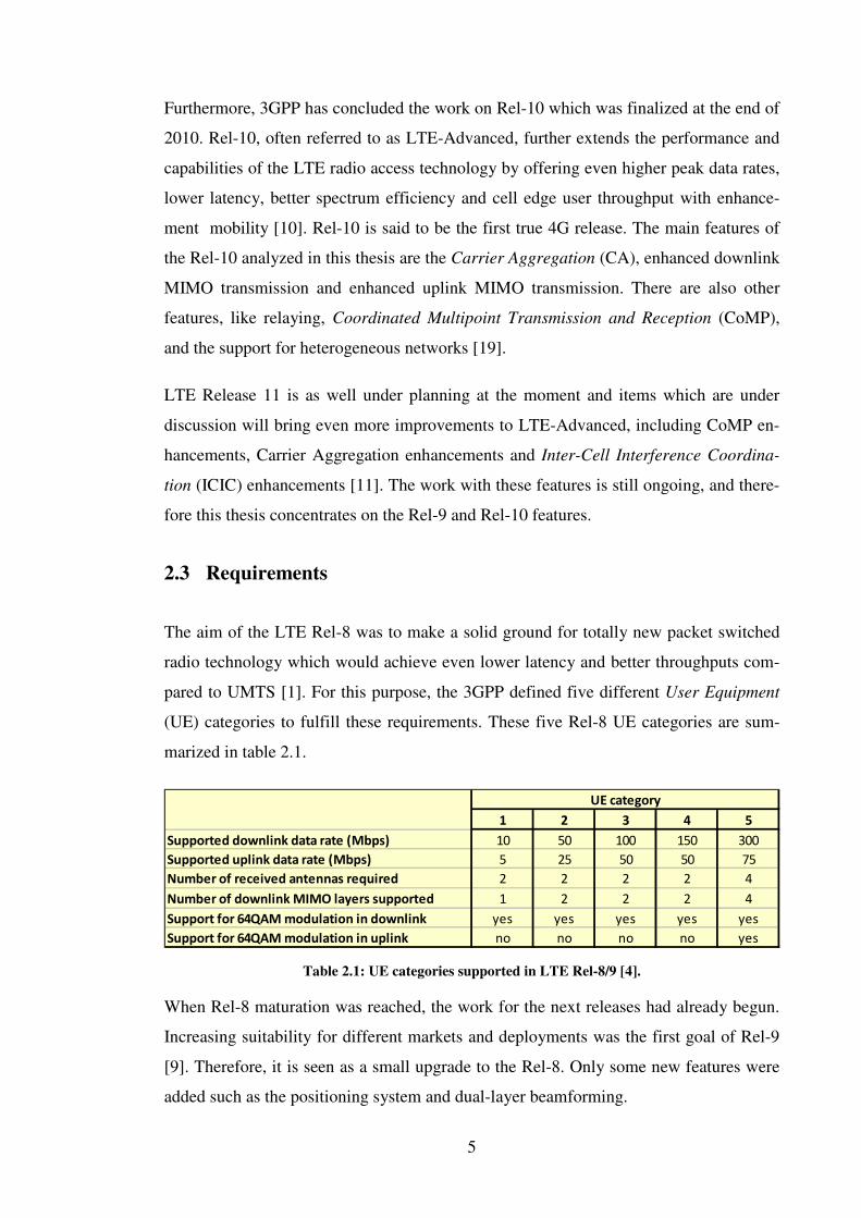
The aim of the LTE Rel-8 was to make a solid ground for totally new packet switched
radio technology which would achieve even lower latency and better throughputs com-
pared to UMTS [1]. For this purpose, the 3GPP defined five different User Equipment
(UE) categories to fulfill these requirements. These five Rel-8 UE categories are sum-
marized in table 2.1.
Table 2.1: UE categories supported in LTE Rel-8/9 [4].
When Rel-8 maturation was reached, the work for the next releases had already begun.
Increasing suitability for different markets and deployments was the first goal of Rel-9
[9]. Therefore, it is seen as a small upgrade to the Rel-8. Only some new features were
added such as the positioning system and dual-layer beamforming.
1 2 3 4 5
Supported downlink data rate (Mbps) 10 50 100 150 300
Supported uplink data rate (Mbps) 5 25 50 50 75
Number of received antennas required 2 2 2 2 4
Number of downlink MIMO layers supported 1 2 2 2 4
Support for 64QAM modulation in downlink yes yes yes yes yes
Support for 64QAM modulation in uplink no no no no yes
UE category

6
As already discussed the focus in 3GPP has shifted to the further evolution of LTE,
called LTE-Advanced. The goal was set to exceed the requirements of IMT-Advanced
which had been specified by the ITU-R in order to satisfy the next generation radio
technology requirements [18, 46]. These requirements were achieved with Rel-10. The
main requirements are shown in the table 2.2. where it can be seen that the Rel-10 was
designed to provide higher peak data rates, lower latency, improved system capacity and
coverage than Rel-8/9 [18].
Table 2.2: Main requirements for the LTE Rel-8/9 and Rel-10 [46].
To achieve the higher data rates, the 3GPP has introduced the carrier aggregation fea-
ture with different downlink and uplink enhancements [10]. For this purpose the 3GPP
has defined three new UE categories in order to fulfill the different requirements be-
tween releases. Table 2.3 summarizes the Release 10 UE categories.
Table 2.3: UE categories supported in LTE Rel-10 [4].
2.4 LTE/SAE system architecture
LTE requirements in general are aiming to enhance the efficiency of bandwidth usage
and to lower latency of the system. Therefore LTE network has been designed to sup-
port only packet-switched traffic with seamless Internet Protocol (IP) connectivity be-
tween UE and SAE gateway [5]. In order to meet these aims, the architecture was high-
ly simplified and flattened, as shown in figure 2.1. The system contains only two types
of nodes named evolved Node-B (eNB) and Mobility Management Entity/SAE Gateway
(MME/SAE GW) [2, 7].
Downlink Uplink Downlink Uplink
Peak spectrum usage efficiency (bps/Hz) >5 >2.5 30 15
Avg. spectrum usage efficiency (bps/Hz) 1.6-2.1 0.66-1.0 2.4-3.7 1.2-2.0
Cell-edge spectrum usage efficiency (bps/Hz) 0.04-0.06 0.02-0.03 0.07-0.12 0.04-0.07
Operating bandwidth (MHz)
LTE Rel-8/9 LTE Rel-10
1.4-20 up to 100
6 7 8
Supported downlink data rate (Mbps) 300 300 3000
Supported uplink data rate (Mbps) 50 100 1500
Number of received antennas required 2 or 4 2 or 4 8
Number of downlink MIMO layers supported 1,2 or 4 1,2 or 4 4
Support for 64QAM modulation in downlink yes yes yes
Support for 64QAM modulation in uplink no no yes
UE category

7
All LTE network interfaces are based on IP protocols and therefore two major changes
were made compared to previous cellular radio architectures. The first major change is
that the Radio Network Controller (RNC) is removed from the data path and its func-
tions are now located in eNB [2]. The main benefits of this type of single node access
network are the reduced latency and the distribution of the RNC processing overhead
into multiple eNBs. The second major change is that there are no nodes for Circuit
Switched (CS) domain, such as the Mobile Switching Centre (MSC). Therefore speech
services are handled as VoIP calls in the LTE network [5, 7].
Figure 2.1: System architecture for LTE Rel-8 network [7].
The eNBs are connected to each other via X2 interface and to EPC through S1 interface,
as also shown in figure 2.1. The S1 interface supports in addition many-to-many rela-
tions between MMEs / SAE Gateways and eNBs [2].

8
SAE Gateway contains two logical gateway entities named as the Serving Gateway (S-
GW) and the Packet Data Network Gateway (P-GW). The S-GW is responsible for re-
ceiving and forwarding IP packets. Therefore, it can be seen as a local mobility anchor
to the eNBs [5]. The P-GW, on the other hand, is responsible for handling the internet
protocol functions, such as address allocation, policy enforcement, packet filtering and
routing [7].
The new system architecture was designed so that it will reduce the overhead from in-
creased traffic. This is achieved because only the MME is responsible for signaling and
therefore the user IP packets do not go through MME. This way the network capacity
stays on a good level as the signaling and the traffic can grow separately [8]. The main
duties of MME are idle-mode UE reachability including the control and execution of
paging retransmission, different type of authentication procedures with Non-Access
Stratum (NAS) signaling, roaming, P-GW/S-GW selection, tracking area list manage-
ment and bearer management including dedicated bearer establishment [5, 7].
2.5 LTE radio access
In order to meet new requirements in section 2.3, the LTE access scheme was designed
to use three new technologies. OFDMA was selected for the downlink transmissions
and SC-FDMA for uplink transmissions. To increase the transmission reliability and
maximize the data throughputs, MIMO was also included to LTE.
2.5.1 OFDMA and SC-FDMA
Orthogonal Frequency Division Multiple Access (OFDMA) is a relatively new technol-
ogy in cellular systems, though the theory of OFDMA was already known in the 1950s
[3]. Available spectrum is divided into multiple carriers in an OFDMA system. These
carriers are called subcarriers which are orthogonal to each other. A large number of
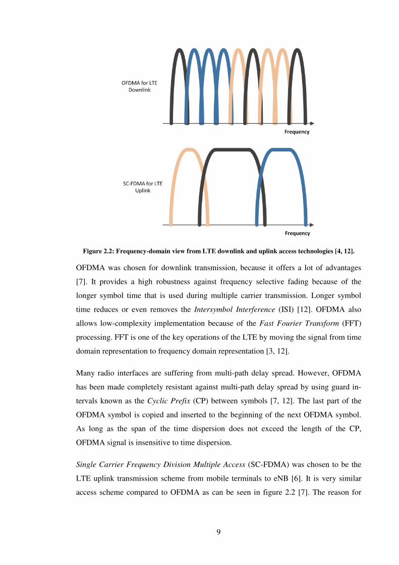
closely spaced subcarriers are transmitted in parallel, as shown in figure 2.2 [12]. Each
subcarrier is modulated at low symbol rate with conventional modulation scheme, like
QPSK, 16QAM or 64QAM [6].
9
Figure 2.2: Frequency-domain view from LTE downlink and uplink access technologies [4, 12].
OFDMA was chosen for downlink transmission, because it offers a lot of advantages
[7]. It provides a high robustness against frequency selective fading because of the
longer symbol time that is used during multiple carrier transmission. Longer symbol
time reduces or even removes the Intersymbol Interference (ISI) [12]. OFDMA also
allows low-complexity implementation because of the Fast Fourier Transform (FFT)
processing. FFT is one of the key operations of the LTE by moving the signal from time
domain representation to frequency domain representation [3, 12].
Many radio interfaces are suffering from multi-path delay spread. However, OFDMA
has been made completely resistant against multi-path delay spread by using guard in-
tervals known as the Cyclic Prefix (CP) between symbols [7, 12]. The last part of the
OFDMA symbol is copied and inserted to the beginning of the next OFDMA symbol.
As long as the span of the time dispersion does not exceed the length of the CP,
OFDMA signal is insensitive to time dispersion.
Single Carrier Frequency Division Multiple Access (SC-FDMA) was chosen to be the
LTE uplink transmission scheme from mobile terminals to eNB [6]. It is very similar
access scheme compared to OFDMA as can be seen in figure 2.2 [7]. The reason for

10
changing the uplink transmission scheme was due to problems in transmission power
that OFDMA causes to mobile terminals [6].
The OFDMA signal introduces very pronounced envelope fluctuations which lead to a
high Peak-to-Average Power Ratio (PAPR) [6, 7]. The high PAPR of OFDMA requires
linear power amplifiers to avoid inordinate intermodulation twist. SC-FDMA offers
better power amplifier efficiency and therefore the scheme is more suitable to use for
uplink and thus in the mobile terminal [6].
Another problem with OFDMA in cellular uplink transmissions derives from the inevi-
table offset in frequency references among the different terminals that transmit simulta-
neously [7]. Frequency offset destroys the orthogonality of the transmission, thus intro-
ducing interference to the channel.
2.5.2 MIMO
One of the fundamental technologies introduced in LTE Rel-8 was the multiple antenna
technique, called Multiple Input Multiple Output (MIMO). MIMO is used to increase
coverage and physical layer capacity by adding more antennas to radio system as seen
in figure 2.3 [3]. In order to achieve the ambitious requirements of throughput and spec-
tral efficiency, MIMO also includes spatial multiplexing and transmit diversity [5].
Figure 2.3: MIMO radio channel access [3].
The basic principle in spatial multiplexing is to transmit different streams of data simul-
taneously on the same resource blocks by utilizing the spatial dimension of the radio
channel [3, 6]. The data, which is transmitted through data streams, may belong to one
single user (single user MIMO/SU-MIMO) or to different users (multi user MIMO/MU-
MIMO) [6].

11
Transmit diversity relies on sending the same stream of data from multiple antennas
with some coding, so the receiver gets replicas of the same signal. This maximizes the
received Signal to Noise Ratio (SNR) at the receiver side and increases the robustness
of data transmission especially in fading scenarios [3, 6].
One remarkable thing about the MIMO operation is that the transmission from each
antenna must be identified so that each receiver can determine what combination of
transmissions has been received [3]. For identification, reference signals are used.
2.6 LTE radio protocol architecture and channels
The general overview from the protocol architecture of LTE is illustrated in figure 2.4.
The protocol is composed of five main tiers on UE side which are Physical Layer
(PHY), Medium Access Control (MAC), Radio Link Control (RLC) and Packet Data
Convergence Protocol (PDCP), and Radio Resource Control (RRC) [2, 4].
Figure 2.4: LTE protocol stack architecture [2, 4].

12
The physical layer controls all lower level handling, like coding/decoding, modula-
tion/demodulation, multi-antenna mapping and other typical physical layer functions [2,
6]. The physical layer offers four services to MAC layer, namely data transfer services,
signaling of HARQ feedback, signaling of measurement reports and scheduling requests
through transport channels.
The MAC layer is responsible for handling the Hybrid-ARQ (HARQ) retransmissions
and scheduling of uplink and downlink [5]. The HARQ functionalities are located in
both the transmitting and receiving end of the MAC protocol layer and the scheduling
part is located only on the eNB side, which has one MAC entity per cell [25]. The MAC
layer provides services to RLC by logical channels.
The RLC layer is responsible for segmentation/concatenation, retransmission handling,
and in-sequence delivery to PDCP layer [5, 6]. The interface between RLC and PDCP is
in the form of radio bearers.
The main purpose of the PDCP layer on the UE control plane side is to provide cipher-
ing and integrity protection [2]. It is also responsible for sequence numbering and dupli-
cate removal. On the user plane side PDCP performs IP header compression to mini-
mize the number of bits sent through radio interface.
The RRC layer, which is also called the higher layer in this thesis, is the main controller
on control plane side [6]. All higher layer configurations arrive from here to the PDCP,
RLC, MAC, and PHY layers. The main purpose for RRC layer is to perform RRC con-
nection management, mobility functions, and UE measurement reporting and control-
ling [5, 6, 25]. On the top of the RRC layer, there is additionally the NAS protocol tier
which performs authentication, security control and SAE bearer control on the control
plane side as was discussed in section 2.4.
When looking at the physical layer channels on the downlink side, it can be seen that six
physical layer channels are defined for LTE as is illustrated in figure 2.5. The physical
channels are Physical Downlink Control Channel (PDCCH), Physical Broadcast Chan-
nel (PBCH), Physical Downlink Shared Channel (PDSCH), Physical Control Format
Indicator Channel (PCFICH), and Physical HARQ Indicator Channel (PHICH). On the
uplink side the physical layer channels are Physical Random Access Channel (PRACH),

13
Physical Uplink Shared Channel (PUSCH) and Physical Uplink Control Channel
(PUCCH).
Figure 2.5: Downlink and uplink channels [14].
Different channels have their own services where every channel has some special pur-
pose in order to fulfill the provided services to the MAC layer. In addition, there are
also different reference signals on downlink and uplink to strengthen the connection
quality. This is discussed more in next section.
2.7 Physical layer general overview
As was shown in previous chapter the LTE physical layer offers four operations to the
MAC layer. In order to fulfill the data transfer services, signaling of HARQ feedback,
signaling of measurement reports and scheduling requests through transport channels
the physical layer have several downlink and uplink transmission features. These fea-
tures contain both control and data transmission schemes.
2.7.1 Physical layer frame structure and resource elements
Before going into the details of LTE transmission, a brief overview of LTE time domain
structure and duplex alternatives for LTE is discussed to understand better how the
transmission itself works [3]. LTE can use both FDD and TDD duplex modes. Although
the time domain structure is very similar, there are some differences between these two
duplex modes which are demonstrated in figure 2.6.

14
Figure 2.6: LTE frame structures [3].
In the case of FDD the downlink and uplink transmissions are on different frequencies.
Therefore, uplink and downlink transmissions can occur simultaneously within a cell
which is illustrated in the upper part of figure 2.6. On the other hand, with TDD trans-
missions, there is only a single carrier frequency and uplink and downlink transmissions
are separated in the time domain on that single cell [5]. Therefore, the switch between
uplink and downlink is made by using the special subframes which are split into three
parts: downlink part (DwPTS), guard period and uplink part (UpPTS). These special
subframes have different periodical configurations on how the frame is switched from
downlink to uplink.
As was discussed in section 2.6, the physical layer provides services to the MAC layer
through different channels. When considering these channels and subframes, it can be
seen that the different channels have their own physical layer areas on a subframe level
which is illustrated in figure 2.7. These areas have been defined with Resource Elements
(RE) which is the smallest unit in physical layer and contains one OFDMA or SC-
FDMA symbol in a time domain [7]. However, for the transmission scheduling the
smallest unit is the Physical Resource Block (PRB) which occupies one slot in a time
domain. Therefore, one PRB contains seven REs on a time domain space.

15
Figure 2.7: Downlink and Uplink structures on a subframe level [5].
2.7.2 Transmission schemes on physical layer
Physical layer features are using several control and data signaling channels on both
downlink and uplink side in order to provide different services to higher layers. Differ-
ent features use different channels to control and transfer data between UE and the net-
work. Therefore this information is mapped to different slots on subframe level, as was
shown in previous section.

16
2.7.2.1 Downlink
On the downlink side, the physical layer signaling corresponds to three different physi-
cal control channels: PCFICH, PHICH and PDCCH which are placed on the first part of
each subframe as shown in figure 2.7. However, the size of control region part can be
varying dynamically between subframes.
The PCFICH is a very important channel for the downlink transmissions as it indicates
the size of the control region in terms of number of OFDMA symbols. This size is also
called Control Format Indicator (CFI) [5]. Correct decoding of the PCFICH infor-
mation is essential because if the PCFICH is incorrectly decoded, the UE is unable to
find the control channels and thus the UE cannot determinate where the data region
starts for that specific subframe [7].
The PHICH carries the acknowledgement response to uplink transmission which has
been transmitted on the uplink by the UE. This operation is called hybrid-ARQ
acknowledgement where the HARQ Indicator (HI) is transmitted [7]. The acknowl-
edgement can be positive (ACK) which means that the data was received and decoded
correctly, or it can be negative (NACK) indicating that the uplink data was not received
and decoded correctly [5].
The most important control signal from the physical point of view is the PDCCH which
carries the Downlink Control Information (DCI) [5]. The DCI is necessary for decoding
the PDSCH correctly as the PDSCH contains the transmitted data. More specifically,
the DCI includes:
• Downlink scheduling assignments, including the PDSCH resource indications.
• Modulation and Coding Schemes (MCS) to the data on PDSCH.
• Transmission Power Control (TPC) commands for controlling the uplink power.
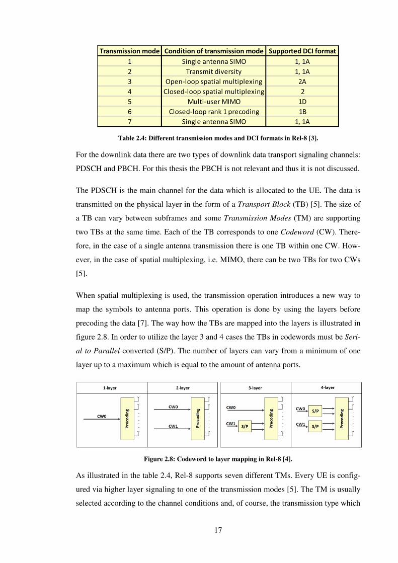
The content of DCI varies between the transmission schemes as can be seen from the
table 2.4. Different DCI formats are defined to control different types of transmissions
which the UE supports.
17
Table 2.4: Different transmission modes and DCI formats in Rel-8 [3].
For the downlink data there are two types of downlink data transport signaling channels:
PDSCH and PBCH. For this thesis the PBCH is not relevant and thus it is not discussed.
The PDSCH is the main channel for the data which is allocated to the UE. The data is
transmitted on the physical layer in the form of a Transport Block (TB) [5]. The size of
a TB can vary between subframes and some Transmission Modes (TM) are supporting
two TBs at the same time. Each of the TB corresponds to one Codeword (CW). There-
fore, in the case of a single antenna transmission there is one TB within one CW. How-
ever, in the case of spatial multiplexing, i.e. MIMO, there can be two TBs for two CWs
[5].
When spatial multiplexing is used, the transmission operation introduces a new way to
map the symbols to antenna ports. This operation is done by using the layers before
precoding the data [7]. The way how the TBs are mapped into the layers is illustrated in
figure 2.8. In order to utilize the layer 3 and 4 cases the TBs in codewords must be Seri-
al to Parallel converted (S/P). The number of layers can vary from a minimum of one
layer up to a maximum which is equal to the amount of antenna ports.
Figure 2.8: Codeword to layer mapping in Rel-8 [4].
As illustrated in the table 2.4, Rel-8 supports seven different TMs. Every UE is config-
ured via higher layer signaling to one of the transmission modes [5]. The TM is usually
selected according to the channel conditions and, of course, the transmission type which
Closed-loop rank 1 precoding
Single antenna SIMO
Transmission mode
1
2
3
4
5
6
7
Condition of transmission mode
Single antenna SIMO
Transmit diversity
Open-loop spatial multiplexing
Closed-loop spatial multiplexing
Multi-user MIMO
Supported DCI format
1, 1A
1, 1A
2A
2
1D
1B
1, 1A

18
the UE needs. The TM1 is the simplest mode where eNB is only using one transmission
antenna. TM2 on the other hand uses transmit diversity usually with two antennas but
also four antennas can be used [7]. These two modes can only use one TB per subframe.
In TM3 two TBs are supported per subframe and therefore spatial multiplexing is need-
ed [5]. TM3 uses open-loop mode with the possibility to do rank adaptation based on
the Rank Indicator (RI) and Channel Quality Indicator (CQI) reporting. These are dis-
cussed later in section 2.7.2.2. It must be noticed that if the rank is set to one, the trans-
mit diversity is used in a similar way as in TM2 [7]. The open-loop operation is shown
on the left side in figure 2.9.
Figure 2.9: Illustrating the open-loop and closed-loop operations [5].
The TM4 is using the closed-loop spatial multiplexing where the UE can use also two
TBs and report the CQI and RI reports to the eNB [7]. The difference between the open-
loop (TM3) and the closed-loop mode (TM4) is that the UE can in addition report the
Precoding Matrix Indicator (PMI) to the eNB. Therefore, the precoding can be deter-
mined by the UE as this is made by the eNB in the case of TM3 [5]. The closed-loop
operation is illustrated on the right side in figure 2.9.
The TM5 is used for MU-MIMO operations where the used mode is similar to the
closed-loop spatial multiplexing, but the information streams are targeted to different
UEs. Because of this, the same resources are shared by multiple users [5].
The TM6 is very similar to the TM4 but the RI is fixed for one layer transmission only
[7]. The TM7, on the other hand, is very interesting as it can be used as a single layer
beamforming where the User Equipment Specific Reference Signal (UE-specific RS) is
used. As TM7 uses reference signals for precoding, there is no need for codebook-based
precoding [4].
Reference signals in downlink transmission are used to carry out coherent demodulation
of different downlink physical channels. Reference signals hold the known amplitude
19
and phase of the subframe. With this information the UE can mitigate the amplitude,
phase and timing errors of the channel [3]. There are two types of downlink reference
signals; the UE-specific RS and the Cell Specific Reference Signal (Cell-specific RS).
The main reference signal is the Cell-specific RS which is used for the channel estima-
tion as it is transmitted in every downlink subframe and for every antenna port [4]. The
UE-specific RS is used to estimate the PDSCH channel, and therefore it is especially
needed in the TDD beamforming. This reference signal enhances the reciprocity of the
TDD duplex mode. Usually every UE in the same cell have their own UE-specific RS
periodicities.
2.7.2.2 Uplink
Regarding the uplink, the main control channel is PUCCH. However, in some situations
there can be some control signaling as well on PUSCH [5]. The PUCCH carries three
types of control signaling also known as Uplink Control Information (UCI). Those are
HARQ ACK/NACK for downlink data, Scheduling Request (SR) indicators, and feed-
back of Channel State Information (CSI). The PRACH is not relevant for this thesis and
thus ignored.
The CSI consists of three main feedback indicators which are the CQI, RI and PMI re-
porting [7]. The reporting of these indicators is done either aperiodically using the
PUSCH or periodically using PUCCH. The RI and PMI reporting are only relevant for
the MIMO transmissions in TM3 and TM4. The PMI reporting can also be used in TM6
as it is a closed-loop transmission scheme but as earlier mentioned in section 2.7.2.1,
TM6 is forced only to one layer transmission [5].
The role of CQI is essential as it indicates the level of noise and interference detected by
the UE [3]. The CQI is computed at the UE for each codeword for the entire transmis-
sion bandwidth (wideband CQI) or to groups of PRB (subband CQI). There are differ-
ent CQI reporting modes that are used by the eNB to maximize downlink transmission
quality.
The RI reporting, on the other hand, represents the preferred number of layers, calculat-
ed by the UE and preferred to be used for the next downlink transmission [3]. Therefore
the maximum number of layers can be limited by the UE for example in the case where
channel conditions are not feasible for high rank transmissions [7].
20
The PMI provides information about the preferred precoding matrix in codebook-based
precoding [3]. The number of precoding matrices in codebook depends on the number
of antennas used by the eNB. However, it must be noticed that the PMI reporting can be
either wideband or frequency selective, depending on the used CQI reporting mode [5].
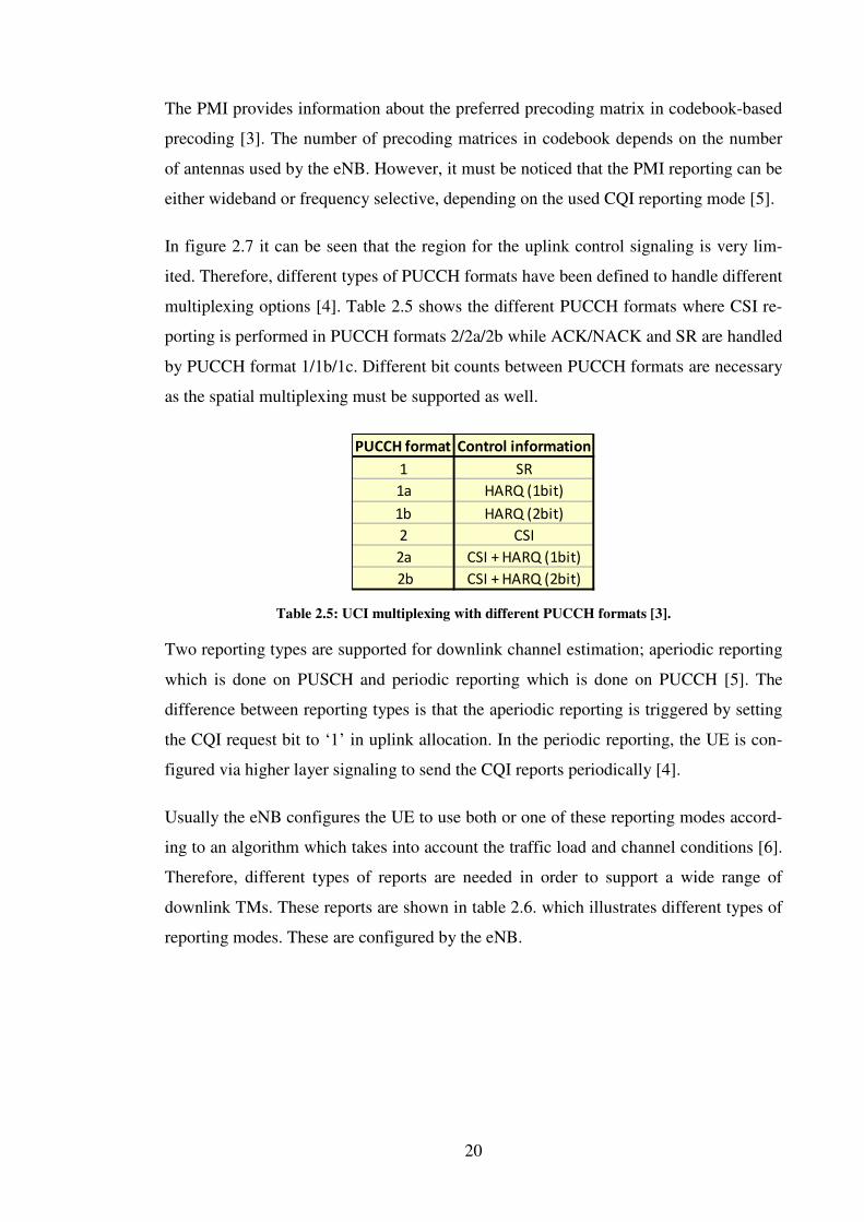
In figure 2.7 it can be seen that the region for the uplink control signaling is very lim-
ited. Therefore, different types of PUCCH formats have been defined to handle different
multiplexing options [4]. Table 2.5 shows the different PUCCH formats where CSI re-
porting is performed in PUCCH formats 2/2a/2b while ACK/NACK and SR are handled
by PUCCH format 1/1b/1c. Different bit counts between PUCCH formats are necessary
as the spatial multiplexing must be supported as well.
Table 2.5: UCI multiplexing with different PUCCH formats [3].
Two reporting types are supported for downlink channel estimation; aperiodic reporting
which is done on PUSCH and periodic reporting which is done on PUCCH [5]. The
difference between reporting types is that the aperiodic reporting is triggered by setting
the CQI request bit to ‘1’ in uplink allocation. In the periodic reporting, the UE is con-
figured via higher layer signaling to send the CQI reports periodically [4].
Usually the eNB configures the UE to use both or one of these reporting modes accord-
ing to an algorithm which takes into account the traffic load and channel conditions [6].
Therefore, different types of reports are needed in order to support a wide range of
downlink TMs. These reports are shown in table 2.6. which illustrates different types of
reporting modes. These are configured by the eNB.
PUCCH format Control information
1 SR
1a HARQ (1bit)
1b HARQ (2bit)
2 CSI
2a CSI + HARQ (1bit)
2b CSI + HARQ (2bit)

21
Table 2.6: Supported feedback modes for PUCCH and PUSCH [6].
P = Periodic / A=Aperiodic
For the uplink, the 3GPP has defined two different uplink reference signals [4]. These
are the Demodulation Reference Signal (DM-RS) and Sounding Reference Signal
(SRS). DM-RS is used for demodulation of uplink data in a similar way as the Cell-
specific RS is used on the downlink side. SRS is used to estimate the channel quality on
eNB side.
2.7.3 Physical layer testing related procedures
Physical layer and MAC layer have several important procedures which are essential to
keep the data connections intact for both downlink and uplink [5]. There are three main
procedures which are essential for this thesis. These are the timing advance, the power
control and the Discontinuous Reception (DRX) procedures.
The timing advance is needed to ensure uplink synchronization between the UE and
eNB [4, 7]. The eNB continuously measures the timing of the UE uplink signal and ad-
justs the uplink transmission timing accordingly. For this purpose the 3GPP has defined
the timing advance commands which are used to adjust the timing.
The LTE power control affects the uplink. For downlink there is no power control on
the UE side. The UE transmission power depends on used bandwidth and data rate and
therefore is highly variable [4]. The uplink power is controlled by the eNB through
pathloss estimation and cell specific parameters received from the UE. These values are
then applied to the correction value which is sent back to the UE. This power control
command from the eNB is indicated in the DCI where the TPC command is used to
22
change the power by one of these correction values; -1dB, 0dB, +1dB, +3dB. However
the maximum uplink power cannot exceed 23dB from the UE which is specified in Rel-
8.
The UE can assist eNB on how to schedule uplink transmission resources. This is done
by reporting the available power headroom to the eNB using the Power Headroom Re-
port (PHR) [7]. This way the eNB can determine how much more uplink bandwidth per
subframe the UE is able to cope with. This prevents the eNB to allocate uplink re-
sources to UEs that cannot be used. The range of PHR is from +40dB to -23dB in Rel-8
[26].
The DRX is configured by the higher layer signaling but it also has aspects which must
be taken into account on the physical layer. The main aspect of the DRX is to reduce the
battery consumption [4]. When in DRX mode the UE does not have to monitor PDCCH
transmissions on every subframe.
2.8 Physical layer in Release 9 and 10
The purpose of Rel-9 was to further expand the feature set of LTE. Thus, it can be seen
more as an upgrade to the Rel-8. The first new feature for Rel-9 was the location system
consisting of a new accurate position method Observed Time Difference Of Arrival
(OTDOA) and enhancement to the Cell ID method encapsulated in the new Enhanced
Cell ID (E-CID). These position improvements have a profound effect to the LTE phys-
ical layer design and thus naturally affect testing and test methods a great deal. These
aspects are discussed in detail in section 4.2. The second new feature which was added
to the Rel-9 is TM8. It was made to improve non-codebook based precoding by provid-
ing the dual-layer beamforming. This was made mainly to increase the TDD data rates.
Similarly, TM8 has a great impact on the physical layer design and thus also on testing,
and therefore TM8 will be discussed at length in section 4.1.
By inspecting the Rel-10 requirements, it can clearly be seen that in order to meet these
requirements, new features and enhancements had to be implemented. To achieve the
improvements to throughput these new features clearly had a wide effect on the physical
layer. In table 2.2 it can be seen that the spectrum usage efficiency has increased in both
downlink and uplink. This was made by adding more physical antennas and introducing

23
two new transmission modes to the physical layer. For the downlink transmission, the
TM9 feature was added to increase the maximum downlink throughput. In order to in-
crease also the uplink throughput the uplink TM2 was added to the release. These new
transmission modes have as well profound effects both on the physical layer design and
on testing, and are studied in sections 5.2 and 5.3 respectively.
It can be seen in table 2.2, that the maximum operating bandwidth has increased from
20MHz to 100MHz. This was achieved by using the Carrier Aggregation (CA) which is
the most important feature in the Rel-10. Section 5.1 is dedicated to this feature.
24
3 LTE FUNCTIONALITY AND PERFORMANCE TEST-
ING
This chapter explains the UE verification cycle from internal R&D integration testing to
external certification testing. Every testing phase has its own specific testing scopes
which are introduced with the testing equipment in order to see more closely how the
testing activities are performed. Ultimately, the aim is to verify the UE functionalities
step-by-step in order to achieve a device which works according to the specifications.
3.1 Overview of R&D UE testing
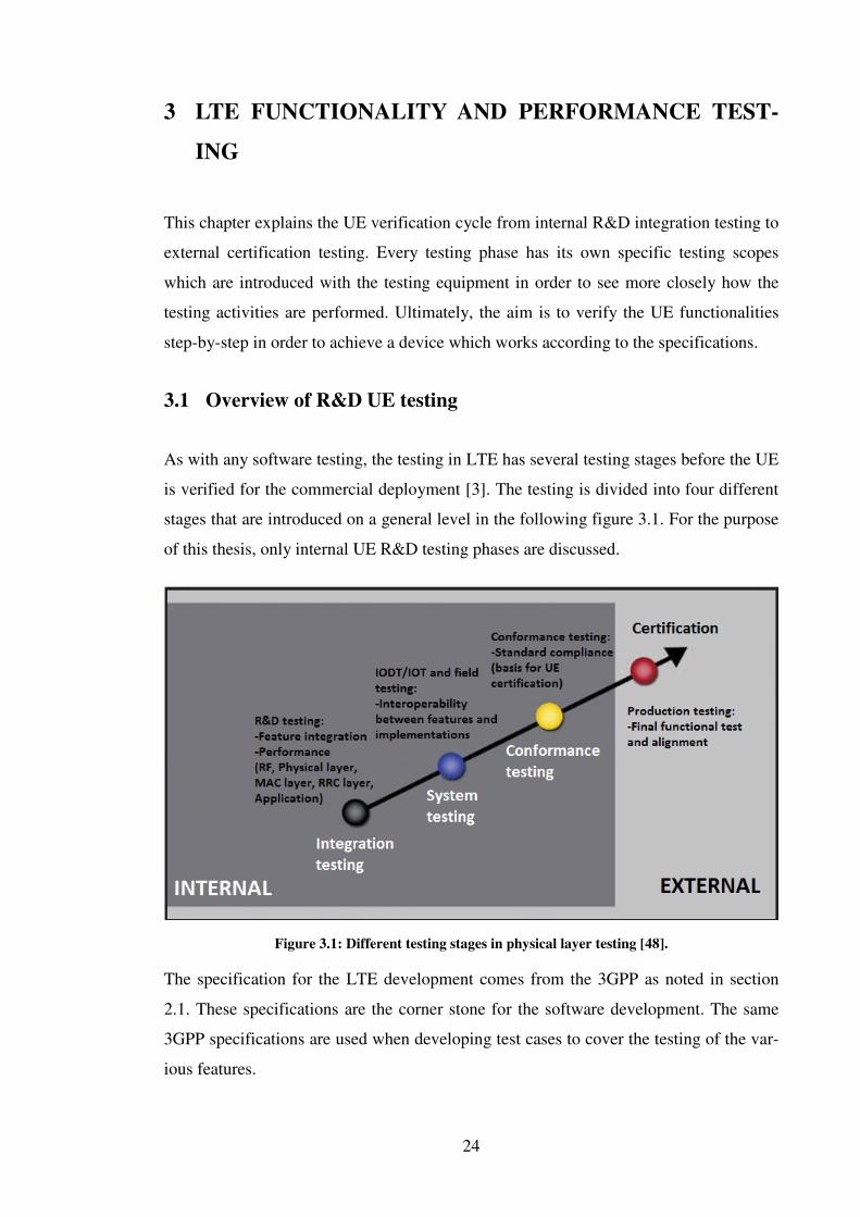
As with any software testing, the testing in LTE has several testing stages before the UE
is verified for the commercial deployment [3]. The testing is divided into four different
stages that are introduced on a general level in the following figure 3.1. For the purpose
of this thesis, only internal UE R&D testing phases are discussed.
Figure 3.1: Different testing stages in physical layer testing [48].
The specification for the LTE development comes from the 3GPP as noted in section
2.1. These specifications are the corner stone for the software development. The same
3GPP specifications are used when developing test cases to cover the testing of the var-
ious features.

25
Regarding the physical layer testing it is started by feature integration [48]. This is when
3GPP release-dependent features are integrated to the main code baseline. The goal of
integration testing is to verify feature integration and also to ensure that the new feature
does not break any old functionality. With a stable baseline the performance testing
which is considered as a part of integration testing can be executed with the aim of
measuring performance with different channel conditions. For example test cases can
measure UE`s downlink and uplink performance in different fading conditions. Integra-
tion testing is performed in laboratory conditions.
Prior to the certification phase, which is performed by third party the LTE, UE software
will go through internal system testing. There are several types of system testing such as
Interoperability (Development) Testing (IO(D)T), conformance testing, and field testing
[3]. These are shown in the figure 3.1. The purpose of system testing is to verify all the
completed and enabled features simultaneously and to confirm the interoperability be-
tween UE and network equipment from various network vendors. The IO(D)T testing is
not covered in this thesis but it is mentioned because it is a part of the verification cycle.
The system testing concentrates on real network operations. These scenarios are exten-
sions of integration test cases with more complexity.
The testing is concluded with the certification phase [48]. This is organized by the PCS
Type Certification Review Board (PTCRB) and Global Certification Forum (GCF)
where the PTCRB is the certification organization in America and the GCF is the certi-
fication organization in Europe and Asia. There are also some country specific certifica-
tion organizations like the Radio and Telecommunications Terminal Equipment
(R&TTE) directive in Finland. Certification testing is external, and not within the scope
of this thesis.
3.2 Simulations of network operations and R&D testing
The physical layer R&D testing analysis begins with the study of the 3GPP specifica-
tions. The goal of this phase is to create a design which takes into account the different
aspects of the new features and are applied across all the different layers of the protocol
stack. The main goal of this thesis is to study a sample of Rel-9 and Rel-10 features
from the physical layer point of view. The information in this thesis will be used to de-

26
fine the testing requirements for the R&D physical layer so that the newly implemented
features can be verified on the system level.
After the requirement analysis has been completed and the testing plan has been created,
the feature integration can be started. This phase consists of implementation of the spec-
ified features, creating the test scenarios for verification and testing of these new fea-
tures. The integration testing is done in a controlled laboratory environment and it is an
essential part of the test cycle. The testing itself is made by using eNB simulators con-
nected to the UE with RF cables. Various other equipment are used as well such as fad-
ing simulators and signal generators. With this kind of equipment it is possible to create
simulated test environments where the features can be tested and verified separately.
One example of the eNB simulator is the Rohde&Schwarz CMW500 protocol tester
which is showed in figure 3.2 [39]. With this particular protocol tester the eNB can be
simulated and different test scenarios can be implemented to take into account different
protocol layers such as the physical layer.
Figure 3.2: R&S CMW500 wideband radio communication tester [39].
Figure 3.3 shows the Rohde&Schwarz AMU200A signal generator and fading simula-
tor. It is used for simulating the different fading conditions in a laboratory environment
and it can be connected to some protocol tester such as the Rohde&Schwarz CMW500.
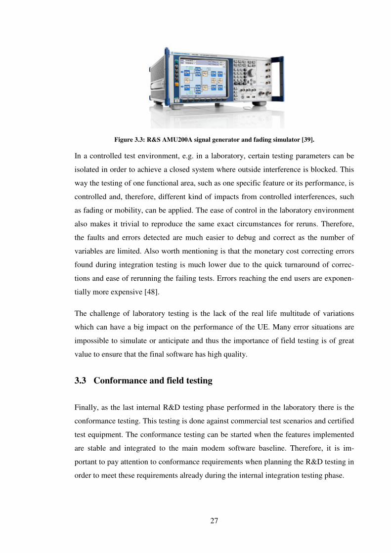
27
Figure 3.3: R&S AMU200A signal generator and fading simulator [39].
In a controlled test environment, e.g. in a laboratory, certain testing parameters can be
isolated in order to achieve a closed system where outside interference is blocked. This
way the testing of one functional area, such as one specific feature or its performance, is
controlled and, therefore, different kind of impacts from controlled interferences, such
as fading or mobility, can be applied. The ease of control in the laboratory environment
also makes it trivial to reproduce the same exact circumstances for reruns. Therefore,
the faults and errors detected are much easier to debug and correct as the number of
variables are limited. Also worth mentioning is that the monetary cost correcting errors
found during integration testing is much lower due to the quick turnaround of correc-
tions and ease of rerunning the failing tests. Errors reaching the end users are exponen-
tially more expensive [48].
The challenge of laboratory testing is the lack of the real life multitude of variations
which can have a big impact on the performance of the UE. Many error situations are
impossible to simulate or anticipate and thus the importance of field testing is of great
value to ensure that the final software has high quality.
3.3 Conformance and field testing
Finally, as the last internal R&D testing phase performed in the laboratory there is the
conformance testing. This testing is done against commercial test scenarios and certified
test equipment. The conformance testing can be started when the features implemented
are stable and integrated to the main modem software baseline. Therefore, it is im-
portant to pay attention to conformance requirements when planning the R&D testing in
order to meet these requirements already during the internal integration testing phase.

28
The goal of the LTE conformance testing is to verify the compliance of UE to 3GPP
standard and to ensure worldwide interoperability of the UE within every viable mobile
network. Therefore, the conformance tests are mainly defined by the 3GPP RAN5 spec-
ification group and developed by the test equipment vendors such as Rohde&Schwarz
[39].
The 3GPP conformance test cases consist of three main parts regarding UE testing: Ra-
dio Frequency (RF), Radio Resource Management (RRM) and signaling. In the pipeline
there are also LTE UE positioning related conformance test cases and these are dis-
cussed more in the sections 4.2.3.1 and 4.2.3.2. The 3GPP has defined the cases in Rel-
9 specification for the UE location system.
The UE RF conformance tests which are defined in 36.521-1 [21], are split into four
main sections: RF transmitter characteristics, RF receiver characteristics, RF perfor-
mance characteristics and reporting of the CQI and the PMI. An example of the UE RF
conformance test system is the Rohde&Schwarz TS8980 LTE RF test system which is
showed in figure 3.4 [39]. Regarding the physical layer the UE RF conformance testing
is very important as there are many cases which are related especially to the physical
layer. Therefore, when planning the internal R&D testing these cases must be taken into
account.
Figure 3.4: R&S TS8980 LTE RF test system [39].
The UE RRM conformance tests, which are defined in 36.521-3 [40], include more UE
mobility related aspects whereas the main testing concentrates on the mobility control
and the UE measurements. These cases are covered later in this thesis as there are as-
pects that must be considered when planning the testing of the new physical layer fea-

29
tures. The last part of the 3GPP conformance test cases is the UE signaling cases which
are defined in 36.523-1, 36.523-2 and 36.523-3 [3]. These cases are related to UE mo-
bility which means that the test scope in these cases is to test UE mobility management
signaling toward the network. These cases have also affected the physical layer testing
but the main focus of this thesis is kept on the RF and RRM cases.
The field testing concentrates on the real life end user scenarios and thus it is more ge-
neric and not specific to single features. Due to the lack of control of the testing envi-
ronment it is much different from laboratory testing. Corrections to errors found during
field testing can be hard to verify due to the complexity and varying conditions of the
channel conditions but these errors are of such nature that they sometimes cannot be
reproduced in laboratory conditions. Thus field testing is of utmost importance.
3.4 UE certification
The UE certifications are controlled by the certification organizations where the two
biggest organizations are the PTCRB and GCF [3]. The members of these organizations
consist of mobile network operators, UE manufactures and chipset manufactures. The
main difference between these organizations is that the PCTRB is responsible for fre-
quency bands mainly used in the Americas, and the GCF is responsible for bands used
in Europe. The 3GPP collaborates with these organizations and therefore some of the
certification test cases are included already in the conformance testing phase.
Additionally operators have their own test requirements which must be met prior suc-
cessful introduction of new wireless products to their markets. Finally, some country
specific conformance testing is required to meet the regulations set by the authorities.
The main focus of the UE certification is to ensure the global interoperability of UEs
and the reliability and performance from the end user point of view. Certification testing
ensures that the various health and safety regulations are met [48]. Therefore, UE certi-
fications can be seen as a quality gateway to ensure that the device works in the real life
conditions and in a global scope.

30
4 LTE RELEASE 9 ENHANCEMENTS AND CHAL-
LENGES TOWARDS PHYSICAL LAYER UE TESTING
This chapter introduces two main features from the physical layer points of view. These
features have thereby a great impact on the Rel-9 UE verification. The first feature con-
centrates on the dual-layer beamforming which has certain testing requirements espe-
cially on data transmission. This feature is discussed in section 4.1 where the TM8 is
first introduced and then analyzed with different testing related aspects in order to verify
the UE in all testing phases and this way to meet the 3GPP requirements.
The second important feature in Rel-9 timeframe is the positioning which introduces
two new positioning methods to LTE called OTDOA and E-CID. These features are
discussed in section 4.2. The discussion starts first by introducing the features and then
turns to analyze different testing aspects. From the physical layer testing point of view
these positioning features have requirements which concentrate especially on the accu-
rate UE positioning.
4.1 Dual-layer downlink beamforming and transmission
The Rel-9 introduces a new downlink spatial multiplexing scheme, called transmission
mode 8 [13]. The TM8 enhances the support for combining spatial multiplexing with
beamforming. This is made by extending the beamforming to a maximum of two data
layers, by using UE-specific reference signals [4].
The UE-specific reference signal-based single-layer beamforming was already intro-
duced in the TM7 in the Rel-8, as discussed in section 2.7.2.1. Because TM7 is mainly
geared toward TDD, the TM8 is as well optimized for TDD [13]. However, TM8 brings
many improvements to downlink transmissions for single user- and multi user-MIMO,
in both FDD and TDD mode. Therefore major TDD operators around the world are fo-
cusing especial on TM7 and TM8. Also due to the beamforming the channel reciprocity
is exploited more efficiently in the TDD case.

31
4.1.1 Rel-9 UE-specific RS
The Rel-9 defines a new design for UE-specific RS. It provides either one or two
streams of data to a single UE in the SU-MIMO case or two streams of data to two UEs
by allocating one layer for each in the same time-frequency resource (MU-MIMO) [4].
With this new UE-specific RS, the TM8 supports a single transmission mode for SU-
MIMO (ranks 1 and 2) and MU-MIMO with dynamic transition between SU-MIMO
rank 1, SU-MIMO rank 2 and MU-MIMO [13]. Because of the dynamic transitions be-
tween ranks, the number of data streams may vary from one time slot to another without
any higher layer signaling, and this is why the UE is required to support fast rank adap-
tation in Rel-9 [17].
From the physical layer point of view the new Rel-9 UE-specific RS is not a straight-
forward extension to Rel-8, but rather a new structure which uses logical antenna ports
7 and 8 [15]. These two antenna ports were designed to be orthogonal, in order to
achieve the separation of spatial layers on the receiver side. As it can be seen in figure
4.1, there are 12 reference symbols per resource block pair and location of the resource
allocation can be changed according to the subframe configuration. However, in the
case of TDD, the UE-specific RS is a bit modified due to the shorter duration of the
DwPTS compared to FDD downlink subframes [6].
Figure 4.1: Rel-9 UE-specific RS structure with normal downlink [6].

32
When considering the backward compatibility with Rel-8, the new UE-specific RS
structure is not suitable for the earlier releases. To avoid overlapping symbols in the
time-frequency grid, the PDSCH mapping must be modified to keep UE-specific RS,
Cell-specific RS and downlink control channels intact. This new mapping of the grid is
only used with UEs supporting the Rel-9 UE-specific RS and therefore it is not an issue
in the network.
4.1.2 DCI format 2B and channel quality feedback
For the downlink scheduling assignment of TM8, a new DCI format 2B was introduced
in the Rel-9 [16]. The transmitted information is very similar to the information in DCI
format 2A, but there is no information of the precoding included, because the precoding
is transparent to the UE and therefore there is no need for the precoder index. The flag
of transport block to codeword swapping is replaced in DCI format 2B to the scram-
bling identity flag which indicates the scrambling code applied for the UE-specific RSs
[4].
From the uplink point of view, the TM8 does not change the handling of the different
multiplexing formats. Same UCI PUCCH formats are used as in Rel-8, which were in-
troduced in section 2.7.2.2.
TM8 uses non-codebook-based precoding similarly to the TM7. The transmission is
precoded on the UE side according to the UE-specific RSs without any knowledge of
the precoding applied at the network side [13]. Although, TM8 also provides the possi-
bility for the UE to help the eNB to derive dual-layer precoding weights by transmitting
PMI/RI feedback. This technique is already well-known from the codebook-based
closed-loop spatial multiplexing and is especially suitable for the FDD deployments
where channel reciprocity cannot be exploited as effectively as in the TDD case [4]. For
the PMI/RI reporting UE can use a defined codebook, but this is only used for the UE
PMI/RI reporting and not for the actual downlink transmission. The UE may also report
the CQI, based on transmit diversity calculated from the Cell-specific RSs, especially
when the MU-MIMO is enabled. The rank and the MCS for the transmission to the UE
are always determined at the eNB [17].
The supported aperiodic and periodic CQI feedback modes of the TM8 are shown in the
table 4.1. Compared to the TM7, the aperiodic reporting supports reporting modes 1-2,

33
2-2 and 3-1. From the periodic point of view the TM8 supports, compared to the TM7,
the reporting modes 1-1 and 2-1 also.
Table 4.1: Transmission mode 8 CQI reporting modes [4].
4.1.3 Testing aspects of transmission mode 8
When considering the TM8 testing, it can be seen that it has features that have already
been defined in Rel-8. However, there are as well some completely new aspects that
have to be taken into account when planning the TM8 testing. The testing must be fo-
cused especially on the spatial multiplexing with beamforming which is made by using
the non-codebook based precoding.
Because the TM8 does not use predefined codebooks, the UE-specific beamforming
introduces new challenges to optimize the channel condition feedback design on UE
implementation side. The reason for this is the interference which the UE faces in TM8.
The interference cannot be cancelled out perfectly and this must be noticed when report-
ing the CQI. It is especially affecting the MU-MIMO CQI reporting because of the in-
ter-user interference. When considering MU-MIMO interference, the SNR plays a ma-
jor role. In order to avoid reporting incorrect CQI values due to interference, the UE
must achieve the maximum SNR [23].
As was previously stated, TM8 is mainly designed to TDD. Therefore, it is a mandatory
feature for Rel-9 UEs which support TDD. In FDD case it is an optional feature and the
support is indicated with the higher layer parameter, called enhancedDualLayerFDD
[35].
From the physical layer R&D point of view there are some features that have to be test-
ed in order to get the TM8 verified properly in the R&D integration phase and later on
in the system testing. These features are DCI format, fast rank adaptation and
34
CQI/PMI/RI feedback. On the TDD side it is also very important to take into account
the special subframes which were discussed in section 2.7.1.
The new DCI format 2B is very similar compared to the DCI format 2A which is used
in TM3. This is fortunate because some testing aspects can be reutilized from Rel-8.
The testing of TM8 must be verified with DCI formats 1A and 2B with bandwidths
ranging from 1.4MHz to 20MHz as well as the supported bands. The normal and ex-
tended CP should also be considered. DCI format 2B does not support the distributed
Virtual Resource Block (VRB) allocations so the testing must be made only with the
localized VRB allocation [16]. In the case of DCI format 1A, the TM8 must be verified
so that the UE is able to receive and precode the transmission correctly from the ports 5,
7 or 8 when using single-layer beamforming. The MCS should also vary from 0 to 28 in
order to verify that the UE can handle different modulation and coding schemes in
TM8.
Additionally to the above, testing aspects to consider for the DCI format 2B are due to
the main difference between DCI format 1A and 2B which is that the DCI format 2B
can allocate two transport blocks. From the testing point of view the 2B should be tested
so that different TBs are used with different modulation and coding schemes in order to
see whether UE can handle the TB to codeword mapping and layer configurations
properly. The UE must also be tested with different antenna setups to see that the UE
can handle both 2 TX and 4 TX antenna transmissions correctly. As already discussed,
the DCI format 2B has the new scrambling identity flag which is calculated in every
subframe and affects the UE-specific RS precoding. This should be verified in order to
see whether the pseudo-random sequence is calculated correctly with the scrambling
identity flag.
The TM8 also supports MU-MIMO which is not supported in TM3. From the UE point
of view this is not a problem because the UE is not aware of other UEs. Only the eNB
knows if the MU-MIMO is enabled during transmission. However, the resource alloca-
tion can vary from SU-MIMO to MU-MIMO dynamically, and because of this the UE
has to be able to handle the fast rank adaptation. In the MU-MIMO state it is important
that the UE can disable one of the codewords and use single-layer beamforming. This
can be tested by setting the redundancy version bit to ´1´ in DCI format 2B. It is also
important to test MU-MIMO so that the UE can receive UE-specific RS from the proper

35
antenna port by enabling one of the New Data Indicator (NDI) bits in the DCI format
2B and verify that the data is received.
As was discussed in the section 4.1.2, the TM8 can also use channel quality feedback to
improve the transmission between the UE and eNB, this is demonstrated in figure 4.2.
The channel state information, i.e. CQI/RI/PMI feedback, is especially useful in the
FDD case as it is helpful for the estimation of the channel reciprocity. However, the
CQI/PMI/RI feedback can also be used with TDD when it is required by the channel
conditions. The TM8 supports both periodic and aperiodic CQI reporting and both must
be tested properly in the integration testing phase. The reports are most useful during
high throughput data transmission in changing channel conditions utilizing optimization
algorithms. Therefore, it is very important to verify the TM8 throughput performance
already in the system testing phase with different kinds of channel conditions and
MIMO schemes.
The Rel-9 has in addition defined one additional higher layer parameter for TM8 to im-
prove the channel conditions between the UE and the eNB [22]. This additional parame-
ter must be tested properly in the R&D integration phase to verify that it will work with
TM8. The parameter is pmi-RI-Report which is defined to help especially in the case of
FDD the network to estimate the channel reciprocity more effectively. This can be seen
in figure 4.2. If the parameter is defined, the UE is configured to report the PMI/RI to
the network and now as well the codebookSubsetRestriction parameter can be used to
restrict the reported PMIs on the UE side. The pmi-RI-Report parameter must be tested
especially in the FDD because it is used to increase especially the channel reciprocity
and thus greatly affects the transmission throughput.

36
Figure 4.2: Transmission mode 8 CSI reporting and data transfer [13].
According to the 3GPP specification [22], some of the CQI feedback modes can be dis-
abled by using feature Group Indicators (FGI) parameter on RRC layer. By using the
parameter, the UE can signal which feature groups are supported by the UE. Regarding
the periodic CQI, the UE can signal to the network that it does not support modes 2-0
and 2-1. Therefore, in order to verify TM8 basic functionality, the testing must be con-
centrated first on the CQI feedback modes which cannot be disabled with the feature
group parameter. These modes are for the periodic CQI reporting 1-0 and 1-1. There is
also an indicator bit in the FGI parameter for the aperiodic CQI reporting modes which
can be used to disabled modes 2-0 and 2-2. Because of this, the aperiodic CQI feedback
testing must be concentrated first on the modes 1-2, 3-0 and 3-1.
Although the 3GPP conformance test specification contains lots of test cases for UE,
there are only a few tests which are related to the beamforming with TM8 [21]. The
specification will contain tests for both TDD and FDD. However, at the time of writing
this thesis, only the TDD cases have been released allowing testing of the single-layer
and dual-layer beamforming.
When studying the beamforming conformance test cases from 36.521-1 [21], it can be
seen that the single-layer transmission happens without simultaneous transmission on
antenna ports 5, 7 or 8, or simultaneously on antenna ports 7 and 8. When the transmis-
sion happens simultaneously, transmission is received on the other port as well which is
not intended for the UE. This case is only considered for the Rel-9 UEs and is obviously
simulating the MU-MIMO case. The test case which uses the dual-layer beamforming
37
simulates the basic SU-MIMO with transmission on antenna ports 7 and 8 in parallel.
This case is only considered for Rel-9 UEs. Testing aspects of this kind must be taken
into account already during the system testing phase as the MU-MIMO feature is very
complicated.
From the FDD point of view, the Rel-9 3GPP conformance test cases had not been re-
leased when this thesis was written. As it was stated before, the FDD needs the CQI
feedback in order to estimate the reciprocity properly. Therefore it can be seen that the
FDD conformance test cases will be similar compared to the TDD but those will also
contain the CQI feedback reporting with periodic modes 1-0 and 1-1, and aperiodic
modes 1-2, 3-0 and 3-1.
The TM8 field testing concentrates on especially verifying the transmission throughput
in real life conditions. As was already discussed in section 3.3, the field test conditions
are dynamic and network conditions cannot be fully controlled. When considering the
TM8 from the field testing point of view, the main issue is the interference. In lab con-
ditions, some of the interference types can be tested but in the field testing interference
types and network conditions are combined. The testing must be done both for SU-
MIMO and MU-MIMO modes. MU-MIMO is especially vulnerable to the inter-user
interference which is present in real life situations.
It is important to choose the field test conditions carefully, because the UE faces differ-
ent kinds of interferences [24]. Examples of such interferences are the urban areas
where UE can face shadowing effects from multistory buildings. There are also signal
reflections from hills, and super refractions and tropospheric refraction from rivers and
the sky. The cell edge, inter-cell interference and the velocity of the UE are also adding
to the interference so these must be considered when planning the field testing loca-
tions.
4.2 Location service - LTE positioning
UE positioning is one of the main LTE Rel-9 features. It refers to a functionality which
determines the physical location of individual UEs in the radio access network. Howev-
er, this is quite a common feature of UEs that have already GPS receivers but there are
cases when GPS service is not available. Another strong motivation for enhancing the

38
positioning in LTE came from Federal Communications Commission (FCC) of USA.
FCC required all mobile network operators in the USA to comply with the ‘E911 Phase
II’ act by January 2013 [4]. These requirements specify the accuracy of the positioning
for emergency services so that 67% of emergency calls need to be located within 50m
and 90% of emergency calls need to be located within 150m.
GPS can easily meet the accuracy requirements but there are situations where GPS sig-
nal is not available due to indoor and urban environment. Therefore, new technologies
are needed. The Rel-9 supports three different positioning techniques, which are Assist-
ed Global Navigation Satellite System (A-GNSS), Observed Time Difference Of Arrival
(OTDOA) and Enhanced Cell ID (E-CID). To enhance the location based services in
Rel-9, a new Location Services (LCS) architecture was introduced to EPS with LTE
Positioning protocols.
The LCS architecture in Rel-9 introduces a positioning server, called Enhanced Serving
Mobile Location Center (E-SMLC), which is located in the core network. Two control-
plane protocols, named LTE Positioning Protocol (LPP) and LPP annex (LPPa) are
standardized in 3GPP to realize the LCS feature. The LPP protocol is executed between
the UE and the E-SMLC, and is transparent to the eNB and MME, as is shown in figure
4.3. On the other hand, the LPPa is executed between the eNB and the E-SMLC, and is
also transparent to the MME.
Figure 4.3: LPP and LPPa protocols in the LTE Rel-9 architecture [4].

39
From the physical layer point of view the most interesting techniques for positioning are
OTDOA and E-CID, although the primary method for positioning in LTE is A-GNSS.
Some of these techniques were already introduced in UTRAN, but Rel-9 brings some
improvements to enhance these location based positioning techniques [4].
4.2.1 OTDOA positioning impact on the physical layer
In the Rel-9 OTDOA, the UE receives the downlink radio transmission of three or more
neighboring cells. The UE utilizes these transmissions for downlink reference signals
and measures the time difference of arrival of the radio frames. This is known as a Ref-
erence Signal Time Difference (RSTD) measurement. These time difference calcula-
tions are then used by the UE or, as earlier discussed, by the E-SMLC to estimate the
UE position using trilateration technique, as is shown in figure 4.4. This is a good back
up method for positioning used when GPS is not available.
Figure 4.4: OTDOA positioning in LTE Rel-9 [4].
4.2.1.1 Positioning reference signals
For the OTDOA, Rel-9 introduces subframes especially for positioning. The reason for
this is that the Rel-8 Cell-specific reference signals suffered from interference between
the neighbor cells which would prevent the accurate RSTD measurements. Positioning
subframes are designed to help the neighbor cells by reducing the interference and in-
creasing the RS strength. These subframes do not carry any PDSCH data, as they pro-
vide Positioning Reference Signals (PRS) [15].

40
As can be seen in figure 4.5, the resource block allocation in the PRS is designed so that
it never overlaps with the PDCCH, or with Cell-specific RSs for any antenna ports [4].
The PRS has its own antenna port number, which is six and only used for PRS transmis-
sion. Between neighbor cells, the PRS patterns may overlap each other, but this can be
avoided by using cell-specific frequency shifts. The PRS is constructed in that way that
it provides more RS strength and utilizes available space in the subframe more efficient-
ly than the Rel-8 Cell-specific RSs. This helps especially in the high interference sce-
narios, as discussed earlier in this section. The configuration for the positioning
subframes is configured by higher layers to the downlink subframes. In TDD deploy-
ments, uplink subframes and special subframes cannot contain PRSs.
Figure 4.5: PRS allocation in subframe [4].
Occasionally the inter-cell interference can be reduced further by muting the PRS
transmission intermittently. This is beneficial when PRS patterns in neighboring cells
are identical to each other. The muting can be activated for specific subframes or even
none in a given positioning occasion [4]. The muted subframes are controlled with a
bitmap which is reported periodically, and it is applied to both the serving cell and to
the neighbor cells.
41
4.2.2 E-CID position for the physical layer
Before going to the OTDOA testing aspects, it is good to introduce the second LTE po-
sitioning technique, called E-CID which has also a large impact on the physical layer
implementation and testing in Rel-9.
The basic Cell ID based positioning estimates the location of the UE by using the
knowledge of the serving eNB. With this basic Cell ID, UE position can only be nar-
rowed down to the physical neighborhood of the signaling tower. However, Rel-9 of the
LTE specification enhances positioning method by adding range and direction infor-
mation for much more accurate positioning. The distance is calculated by estimating the
Round Trip Time (RTT) of the signaling between the UE and the serving eNB. Angle of
Arrival (AoA) is used to estimate the direction to the UE from serving eNB.
4.2.2.1 Timing advance measurements
The RTT is estimated by using timing advance operations which calculate the reception
and transmission timings at the UE and eNB. Two kinds of measurement types are de-
fined in the Rel-9 and are used to calculate the RTT in the E-SMLC [4].
The timing advance type 1 measurement is defined as the sum of the duration it takes
for the UE to receive a transmission from the eNB and vice versa the duration of eNB
receiving transmission from the UE. The UE reports its own time difference to the eNB
which then calculates the average RTT from the UE report and its own report. The Tim-
ing Advance Type 1 method can only be used for UEs supporting Rel-9.
The other measurement type, the timing advance type 2, calculates also the time differ-
ence of the receive-transmit duration. However, this is done by using the radio frame
containing a PRACH and the calculations are made only at the eNB. Type 2 measure-
ments can also be made to the Rel-8 UEs, because the distance of the UE is calculated
on the eNB side and the accuracy depends on the PRACH detection which is typically
of the order of 1-2 micro seconds, depending on the channel conditions [4].
By using the RTT to estimate the UE distance, it can still be difficult to get the overall
location, because it does not provide any directional information. This has been solved
by using the AoA when the UE direction is calculated from uplink signals from the UE

42
at the eNB [4]. In general, any uplink signal from the UE can be used, but typically a
known signal such as the SRS or DM-RS is used for this purpose.
4.2.3 Testing of LCS positioning methods in LTE
As there are three different positioning operations defined for LTE; A-GNSS, OTDOA
and E-CID, it is useful to consider which of the positioning operations should be used. It
was previously said that the primary method will always be the A-GNSS but when the
satellite signal is not available, which one of the positioning methods, OTDOA or E-
CID, should be chosen by the UE?
It is agreed that the OTDOA will be the backup method for A-GNSS because it is more
accurate than E-CID. Also with A-GNSS and OTDOA, the UE is able to meet the FCC
requirements in accurate positioning [4]. However, in some cases the OTDOA cannot
be used instead of A-GNSS because the OTDOA needs at least three eNBs in order to
calculate the accurate position. This can occur especially in rural environments where
the eNBs are placed sparser. In such situations, the UE will use the E-CID for the posi-
tioning.
It is clear that the main thing to be tested from the physical layer point of view is the
measurement accuracy in both OTDOA and E-CID. There are many aspects that must
be taken into account to achieve the measurement accuracy.
4.2.3.1 OTDOA testing
The main operation of OTDOA, in order to achieve the measurement accuracy, is to
calculate the RSTD correctly in different scenarios and with different configurations.
The OTDOA position operation is UE-assisted method and therefore the position calcu-
lation is done in the E-SMLC using LPP protocol. The LPP is a higher layer protocol
but it has some operations which are also affecting the physical layer configuration on
the UE and these operations must be tested carefully during internal integration R&D
testing.
In order to estimate the RSTD from at least three eNBs, the UE must be able to receive
the PRSs from multiple cells at the same time, as can be seen from figure 4.6. The PRSs
are mapped around the carrier frequency to avoid collisions and overlaps with Cell-
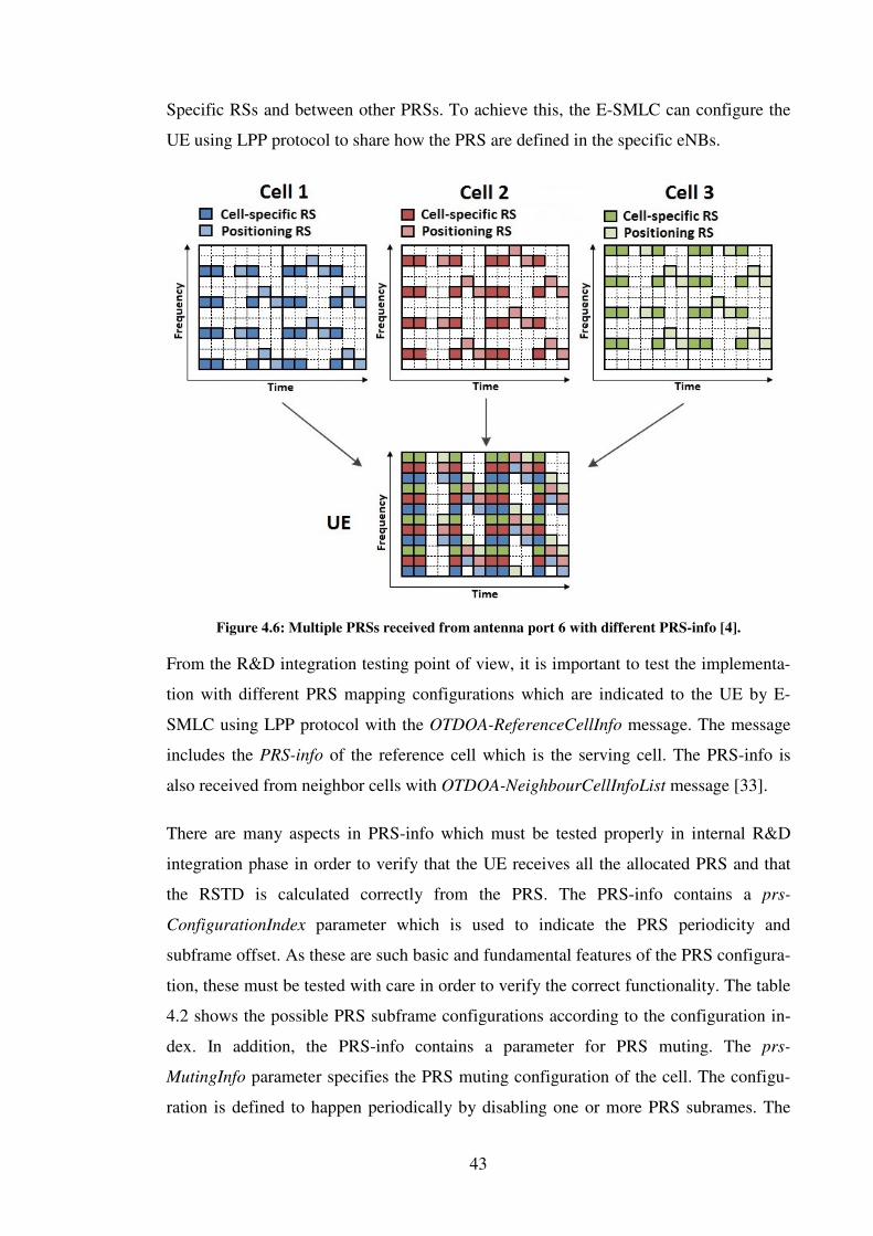
43
Specific RSs and between other PRSs. To achieve this, the E-SMLC can configure the
UE using LPP protocol to share how the PRS are defined in the specific eNBs.
Figure 4.6: Multiple PRSs received from antenna port 6 with different PRS-info [4].
From the R&D integration testing point of view, it is important to test the implementa-
tion with different PRS mapping configurations which are indicated to the UE by E-
SMLC using LPP protocol with the OTDOA-ReferenceCellInfo message. The message
includes the PRS-info of the reference cell which is the serving cell. The PRS-info is
also received from neighbor cells with OTDOA-NeighbourCellInfoList message [33].
There are many aspects in PRS-info which must be tested properly in internal R&D
integration phase in order to verify that the UE receives all the allocated PRS and that
the RSTD is calculated correctly from the PRS. The PRS-info contains a prs-
ConfigurationIndex parameter which is used to indicate the PRS periodicity and
subframe offset. As these are such basic and fundamental features of the PRS configura-
tion, these must be tested with care in order to verify the correct functionality. The table
4.2 shows the possible PRS subframe configurations according to the configuration in-
dex. In addition, the PRS-info contains a parameter for PRS muting. The prs-
MutingInfo parameter specifies the PRS muting configuration of the cell. The configu-
ration is defined to happen periodically by disabling one or more PRS subrames. The
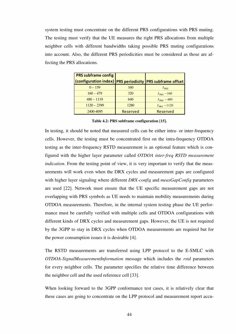
44
system testing must concentrate on the different PRS configurations with PRS muting.
The testing must verify that the UE measures the right PRS allocations from multiple
neighbor cells with different bandwidths taking possible PRS muting configurations
into account. Also, the different PRS periodicities must be considered as those are af-
fecting the PRS allocations.
Table 4.2: PRS subframe configuration [15].
In testing, it should be noted that measured cells can be either intra- or inter-frequency
cells. However, the testing must be concentrated first on the intra-frequency OTDOA
testing as the inter-frequency RSTD measurement is an optional feature which is con-
figured with the higher layer parameter called OTDOA inter-freq RSTD measurement
indication. From the testing point of view, it is very important to verify that the meas-
urements will work even when the DRX cycles and measurement gaps are configured
with higher layer signaling where different DRX-config and measGapConfig parameters
are used [22]. Network must ensure that the UE specific measurement gaps are not
overlapping with PRS symbols as UE needs to maintain mobility measurements during
OTDOA measurements. Therefore, in the internal system testing phase the UE perfor-
mance must be carefully verified with multiple cells and OTDOA configurations with
different kinds of DRX cycles and measurement gaps. However, the UE is not required
by the 3GPP to stay in DRX cycles when OTDOA measurements are required but for
the power consumption issues it is desirable [4].
The RSTD measurements are transferred using LPP protocol to the E-SMLC with
OTDOA-SignalMeasurementInformation message which includes the rstd parameters
for every neighbor cells. The parameter specifies the relative time difference between
the neighbor cell and the used reference cell [33].
When looking forward to the 3GPP conformance test cases, it is relatively clear that
these cases are going to concentrate on the LPP protocol and measurement report accu-
PRS subframe config
(configuration index) PRS periodicity PRS subframe offset
0 – 159 160
160 – 479 320
480 – 1119 640
1120 – 2399 1280
2400-4095 Reserved Reserved
PRSI
160PRS −I
480PRS −I
1120PRS −I
45
racy, as compliance to the new FCC requirements are of great importance. Because this
thesis concentrates on the physical layer testing, the LPP protocol is left out and only
measurement accuracy test cases are considered.
The 3GPP has defined in the specification 37.571-5 [32] the assistance data for OTDOA
position test cases which should be used in all OTDOA test cases. In order to fulfill the-
se initial requirements, the UE must be able to measure PRSs from 16 eNBs with differ-
ent periodical and muted configurations. The most interesting conformance test cases
from the physical layer point of view are specified in specification 37.571-1 [31]. Natu-
rally, the specified conformance test cases for OTDOA should be already included part-
ly in the internal R&D performance testing phase in order to fulfill these requirements
from UE performance point of view. If the internal system testing is performed with
only a couple of cells, measurements of 16 eNBs can have a deteriorating effect on the
UE performance.
3GPP has specified two types of conformance tests for OTDOA in 37.571-1 [31]. The
first set of test cases test the measurement reporting delay in order to verify that the
RSTD measurement reporting delay meets the requirements in an environment with
fading propagation conditions in FDD and TDD mode. The second set of test cases are,
on the other hand, concentrating on the measurement accuracy to verify that the RSTD
intra-frequency measurement accuracy is within the specified limits in FDD and TDD.
When considering the field testing of OTDOA position method, the main testing aspect
is to verify accurate measurements and thereby achieve accurate positioning. In real life
networks there are a lot of interference types as were already discussed in section 3.3
and 4.1.3. The interference affects the RSTD measurements especially in the cases
where the UE is configured to receive PRS from multiple cells. It is interesting to see
how the PRS is able to adjust to the SNR distribution which has very strong impact on
the UE interference [27]. This causes especially timing offset estimation errors for the
UE. However, the interference is not the only problem; there are also other practical
considerations which may have an impact on the final accuracy of the location esti-
mates.
The multipath fading channel has interesting aspect to the positioning accuracy as it
introduces errors in the propagation delay estimation. This so called non-LOS effect is
critical to the OTDOA performance as it brings large variations to the signal strength

46
which affects the accuracy [27]. There are also other interesting field test aspects, like
the UE quantization errors and UE frequency stability issues which are not affecting the
physical layer that much [29]. The UE may deal with these issues individually, but the
field testing must pay attention to the possibility that there are simultaneous issues
which complicate OTDOA positioning accuracy.
4.2.3.2 Testing of E-CID positioning method
As was already stated in section 4.2.2, the E-CID is the final and least accurate position-
ing method. At the moment it is unclear how the operators will start to support these
new positioning methods. The cost of transition to use E-CID is lower than OTDOA
because it is an extension of Cell ID method, although the E-CID will also use the LPP
and LPPa protocols. The UE testing should concentrate on the two types of E-CID de-
ployment scenarios which are described next.
The main idea is that the E-CID is used if the OTDOA cannot be used, i.e. when there
are less than three eNBs in range. Then the position can be made by using the eNB-
assisted E-CID method where the E-SMLC calculates the position according to the in-
formation from one eNB. The calculation is done by using the RTT and AoA [34]. Be-
cause the method is eNB-assisted, there are only few things to be tested on the UE side.
In the eNB-assisted E-CID, the RTT is calculated on eNB with measurement type 1
because the type 2 is only applicable during the PRACH. The eNB measures first its
own timing difference and instructs the UE to correct its uplink timing as received in the
timing advance command. After that the UE measures and reports its receive-transmit
timing difference to the eNB. The measurement request is indicated to the UE with
ECID-RequestLocationInformation message by the location server [33]. Because this is
an eNB-assisted scenario, the UE sends the time difference measurement results to the
E-SMLC with ECID-SignalMeasurementInformation message which is a LPP message.
There is a parameter, called ue-RxTxTimeDiff which indicates the receive-transmit tim-
ing difference of the serving eNB.
In addition to the serving cell receive-transmit timing difference, the UE can be config-
ured with the same ECID-SignalMeasurementInformation message to transfer the serv-
ing cell and to the neighbor cells RSRP/RSRQ measurements to the E-SMLC. These
measurements can increase the positioning accuracy when using the networks

47
RSRP/RSRQ map. By comparing the RSRP/RSRQ map to the UE measured
RSRP/RSRQ values, the UE position can be estimated even better.
From the internal R&D integration testing point of view it is important to verify that the
timing advance is estimated correctly in order to achieve an accurate receive-transmit
timing value. The uplink timing can vary between the measurements and therefore the
UE must be able to adapt to the jittering effectively. From the performance point of
view the timing difference is very vulnerable for latencies and delays. Because of this,
any performance latencies and delays should be minimized in the UE. This is the case
especially when the RSRP/RSRQ map is used for the UE positioning and the UE is con-
figured to measure the RSRP/RSRQ values from up to 32 cells. Therefore, it is im-
portant to verify that the UE is able to achieve accurate positioning even in high per-
formance test cases where extra measurements can cause overhead to the time differ-
ence calculations.
The 3GPP has so far defined two conformance test cases for E-CID in 37.571-1 [31],
one for FDD and one for TDD. Both cases are similar and use different bandwidths. The
test cases are more likely to concentrate on the first scenario where the UE measures the
receive-transmit time difference from the serving cell. The main idea in both cases is to
test the timing difference measurement accuracy so that the reported values are within
the limits of the specification. It should also be noticed that in the conformance test cas-
es the uplink transmission timing does not change although this is a common situation
in a real life network.
When the field test planning is started for the E-CID positioning method, the testing
aspect should especially concentrate on the scenarios where the speed and channel con-
ditions are affecting the RTT. From the UE point of view, the field testing should be
performed especially in urban environment where the non-LOS is heavily affecting the
signal and the RTT is more difficult to estimate [30]. Testing should also cover, how the
cell edge affects to the uplink power control in the case of non-LOS, because this effects
on the AoA estimation on eNB [28]. Without a good uplink power control the eNB es-
timation of the AoA can be incorrect. AoA estimation is already very difficult in urban
environment where the angular spread is large. It will be very interesting to see the ef-
fects of high speed on the uplink timing and on the UE performance when it needs to

48
update the timing advance frequently. Finally, it can be said that the E-CID must be
tested in urban environment especially at the cell edge and when speed affects the UE.

49
5 LTE RELEASE 10 IMPACT ON PHYSICAL LAYER
TESTING IN LTE-ADVANCED
This chapter concentrates on the Rel-10 features and on the first steps towards LTE-
Advanced deployments. The main features, from the physical layer point of view, of
this chapter are the CA, downlink MIMO enhancements and uplink MIMO. All the new
features are first introduced and then analyzed in this chapter. This kind of approach
gives a better understanding of which enhancements have been deployed and how these
enhancements must be tested in order meet the 3GPP requirements with different testing
phases.
The CA is the most important feature in Rel-10 and therefore the CA has plenty of test-
ing requirements which are discussed in section 5.1. Also different CA deployment sce-
narios and testing activities related to those scenarios are analyzed in order to have a
better understanding of how the CA will make a viable commercial option. Downlink
MIMO enhancements and the uplink MIMO features have as well testing requirements
which are mostly related to data transmission and channel quality functions and these
are analyzed in sections 5.2 and 5.3.
5.1 Carrier aggregation
As was already discussed in section 2.8, the carrier aggregation is one of the key parts
of Rel-10 in order to increase the peak data rates [19]. The CA allows also other ad-
vanced features, like multi-carrier scheduling, quality-of-service differentiation, carrier
load balancing, interference coordination, and heterogeneous deployments [4]. Especial-
ly, the multi-carrier scheduling is used for increasing the throughput by scheduling the
users to carriers that are experiencing less interference. Similarly, the interference coor-
dination is used for scheduling the users in a manner that will generate less interference
with the surrounding cells. The carrier load balancing focuses on increasing the usage of
the fragmented spectrum and the heterogeneous deployments are beneficial to support
areas where cells are using different power levels and coverage areas.

50
Figure 5.1: Different carrier aggregation deployment scenarios [45].
The main idea of the carrier aggregation is to use multiple Component Carriers (CC) to
extend the maximum bandwidth in the downlink and uplink transmission as illustrated
in figure 5.1. The carriers that are aggregated are Rel-8 carriers. This ensures backward
compatibility. Up to five CCs can be combined to achieve the maximum 100MHz
bandwidth. Also, each CC can use any of the Rel-8 transmission bandwidths, i.e.
1.4MHz, 3MHz, 5MHz, 10MHz, 15MHz and 20MHz [19]. Because of the limitations
of the spectrum that operators are using, three aggregation scenarios are introduced. The
possible scenarios are contiguous spectrum aggregation in a single radio band (intra-
band), non-contiguous spectrum aggregation in a single radio band (intra-band), and
non-contiguous spectrum aggregation in multiple radio bands (inter-band), as can be
seen in figure 5.2. It is possible for the UE to use a different number of CCs in the up-
link than in the downlink transmission. However, in the TDD case, the number of CCs
in the uplink and downlink are typically the same.
Figure 5.2: Carrier aggregation bandwidth allocations [6].
When carrier aggregation was decided to be included into the Rel-10 features, it was
obvious that it would have an impact on the LTE architecture, which can be seen in fig-

51
ure 5.3. From the higher-layer point of view, each CC can be seen as individual cell
with its own cell ID as well as all Rel-8 channels and signals [4, 19]. Because of this,
the backward compatibility to earlier releases and the re-use of Rel-8 technology was
made possible. The UE which is configured to use carrier aggregation, uses one Prima-
ry Serving Cell (PCell) and up to four Secondary serving cells (SCell). The PCell acts as
a primary cell that handles the initial configuration during connection establishment,
such as NAS and mobility information. The SCell may be configured after the connec-
tion establishment to provide additional radio resources, however the UE identity is the
same in the PCell and its configured SCells. The CCs corresponding to PCell are de-
fined as Downlink and Uplink Primary Component Carrier (PCC) and SCell carriers as
Downlink and Uplink Secondary Component Carrier (SCC). The linkage between up-
link and downlink CCs is signaled in SIB2 on each downlink carrier. Also, the same
frame structure is used in all linked aggregated serving cells, and for the TDD carrier
aggregation, the uplink-downlink configuration across all serving cells is the same [4].
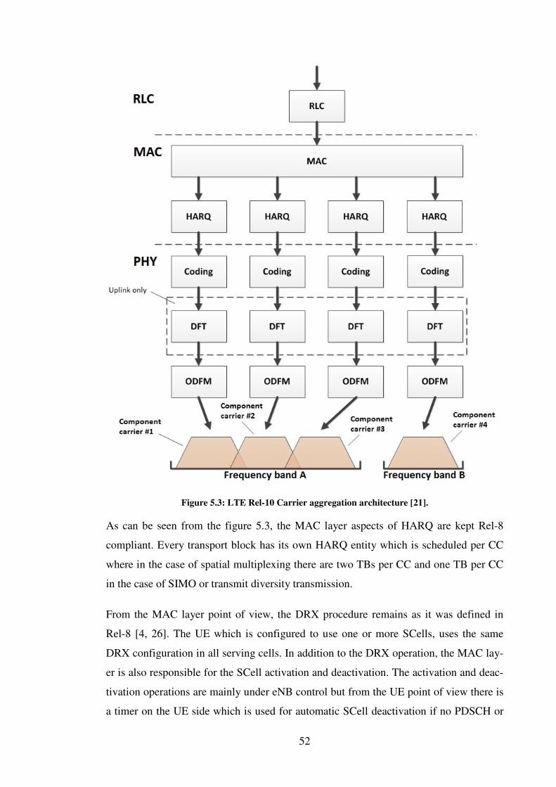
52
Figure 5.3: LTE Rel-10 Carrier aggregation architecture [21].
As can be seen from the figure 5.3, the MAC layer aspects of HARQ are kept Rel-8
compliant. Every transport block has its own HARQ entity which is scheduled per CC
where in the case of spatial multiplexing there are two TBs per CC and one TB per CC
in the case of SIMO or transmit diversity transmission.
From the MAC layer point of view, the DRX procedure remains as it was defined in
Rel-8 [4, 26]. The UE which is configured to use one or more SCells, uses the same
DRX configuration in all serving cells. In addition to the DRX operation, the MAC lay-
er is also responsible for the SCell activation and deactivation. The activation and deac-
tivation operations are mainly under eNB control but from the UE point of view there is
a timer on the UE side which is used for automatic SCell deactivation if no PDSCH or

53
PDCCH messages are received during a specified time period. However, similar timer
is as well configured by the eNB. In order to achieve common understanding between
the eNB and the UE, the activation timing must be defined precisely. If the eNB acti-
vates a new SCell for the UE in a subframe n, the UE must be ready to monitor the
PDCCH for both uplink grants and downlink assignments in subframe n + 8. There are
also many physical layer related operations that can be assumed to be started in
subframe n + 8, such as SRS transmission, CSI measurements, and power headroom
reporting.
5.1.1 Physical layer aspects to the Carrier Aggregation
At the physical layer, all the main features are as in Rel-8; transport block mapping,
modulation, coding, and resource allocation as well as the corresponding signaling.
These are performed independently on each CC [4]. However, there are some improve-
ments that have to be taken into account for achieving the smooth carrier aggregation
between CCs. The effects of carrier aggregation on the LTE physical layer mainly con-
cern feedback structures for multiple carriers but there are also changes to the single
carrier uplink operations, with the introduction of the discontinuous PUCCH/PUSCH
and PUSCH/PUSCH allocations.
5.1.1.1 Downlink control signaling
In Rel-8 PDCCH was designed to carry downlink resource assignments for its own CC.
Similarly, the uplink resource grants are associated with uplink CC which is pointed in
SIB2. When using the carrier aggregation, interference between CCs must be avoided.
For this a new key feature is designed, called cross-carrier scheduling. This enables a
possibility to schedule multiple resource assignments in one PDCCH area with new 3-
bit Carrier Indicator Field (CIF) [4]. The CIF is located at the beginning of the DCI and
is fixed regardless of DCI format size. It supports cross-carrier scheduling for DCI for-
mats 0, 1, 1A, 1B, 1D, 2, 2A, 2B and 2C in the UE specific search space [16]. The pres-
ence of the CIF value on each CC is configured by higher-layer signaling on each UE.
In cross-carrier scheduling the UE may expect to receive downlink assignment schedul-
ing messages on the PDCCH for one or more CCs. In this case the data may be either on
the same CC, or on the different CCs as can be seen from figure 5.4. The PDCCH moni-
toring happens for the serving cell where the UE searches PDCCH messages at any rate

54
for the same CC of the serving cell, as can be seen also from the figure 5.4. The CIF
value in DCI format indicates the cell index which is used for the cross-carrier schedul-
ing. With cell index it is easy to indicate the corresponding CC where the PDSCH or
PUSCH transmission takes place [4]. If CIF is not configured to the DCI format, the
uplink grant or downlink assignment received on a given serving cell corresponds to
PUSCH or PDSCH transmission on the same serving cell.
Figure 5.4: LTE Rel-10 cross carrier scheduling [6].
5.1.1.2 Uplink control signaling
When inspecting the uplink control signaling aspect from the CA point of view, it can
be seen that there are changes in both HARQ and Channel state information feedback.
These changes bring totally new aspects to uplink feedback reporting and therefore the-
se are extremely important features to physical layer. Discussion starts with the HARQ
related aspects and turns after that to Channel state information changes.
For carrier aggregation, more changes are required in the design of the uplink control
signaling than for the downlink. This is because of the transmission power limitation at
the UE and the need to support asymmetric downlink and uplink carrier configurations.
This means that UE may send a HARQ ACK/NACK for every downlink transport
block, i.e. up to ten per subframe in the case of downlink spatial multiplexing with up to
55
five CCs [4]. Because the Rel-8 PUCCH was not designed to carry such a large number
of ACK/NACK bits, new operations have been defined to Rel-10.
In order to provide HARQ feedback for PDSCH transmission on multiple CCs, new
multibit ACK/NACK PUCCH formats are defined in Rel-10 to support carrier aggrega-
tion [17]. These formats are PUCCH format 3, which is a totally new format, and the
PUCCH format 1B, which was already defined in Rel-8 but is now extended with chan-
nel selection [6].
The PUCCH format 3 is designed especially for the carrier aggregation to transmit large
ACK/NACK payloads [6]. Therefore, PUCCH format 3 is designed to use DFT-
precoded OFDM, and is thus similar to PUSCH transmission [17]. The PUCCH format
3 is able to support transmission of 48 coded bits, but the actual number of bits used to
ACK/NACK feedback is determined from the number of configured CCs and config-
ured transmission modes on each of the CCs. Also in the TDD mode the used
ACK/NACK bundling window affects the number of used bits, and so the highest pay-
load size for the TDD case is 20 HARQ bits. Additionally, one bit for a positive or neg-
ative SR is appended to the end. In the FDD case, the highest payload size for PUCCH
format 3 is 10 bits with the addition of one bit for positive or negative SR. Finally, it is
important to point out that, because of the differences in underlying structures between
PUCCH format 3 and the other formats, resource blocks cannot be shared between these
format types.
The PUCCH format 1B expanded with channel selection provides multibit HARQ feed-
back to support carrier aggregation [4, 17]. This involves configuring up to four
PUCCH format 1B resources, and choosing one of these resources leads to some
ACK/NACK information transition. However, PUCCH format 1B is supported only in
cases with two configured CCs. If more CCs are allocated to the UE, then the PUCCH
format 3 is needed.
In the FDD case, it is straightforward for two CCs to use of PUCCH format 1B with the
channel selection to transmit the ACK/NACK information. It is necessary that TDD
utilizes spatial bundling of ACK/NACK bits between the two codewords within a
downlink subframe for each of the serving cells if the number of ACK/NACK bits ex-
ceeds four [4]. In the case the number of ACK/NACK bits after performing spatial bun-
dling is still greater than four; additional time-domain bundling is used. The PUCCH

56
format 1B with channel selection enhances the old PUCCH format 1B significantly. It
allows the UE, in the FDD case, configuration of several serving cells. However, it is
also backward compatible with Rel-8, both for the TDD and the FDD where the UE
uses a single configured CC.
As in Rel-8, the information of channel conditions must be transmitted in the case of
CA [17]. Therefore the transmissions of CQI, RI, PMI and Precoding Type Indicator
(PTI) are discussed next as the CA will bring some new aspects to the channel state in-
formation. The PTI bit is introduced more closely in section 5.2.3 as it is a new feature
of Rel-10.
In the Rel-10, channel state information can be send periodically or aperiodically, as in
Rel-8 [17]. However, in the Rel-10, the periodic CSI is reported only for one downlink
CC in any given subframe. This causes collisions between reports, because for example
with the carrier aggregation there might be four downlink CCs and only one uplink CC
to transmit the reports. To avoid the collisions between the reports in the FDD mode,
different offsets and periodicities should be used for the different carriers. For instance,
subband CQI reporting may be configured on the primary downlink carrier with only
wideband reporting configured for secondary carriers. However, a collision of multiple
CSI reports may still occur and then the prioritization rules are used, as shown in table
5.1, and only one report is selected for transmission. From the UE point of view, there
are no prioritizations between serving cells, but in the case of multiple CCs with the
same report priority, the CC of the serving cell which has the lowest cell index is used.
Table 5.1: Periodic CSI reporting prioritization in the case of collisions [4].
When the UCI is used with the carrier aggregation, it is good to notice how the multiple
serving cells are affecting the uplink control transmissions. The UCI is transmitted on
the PCC PUSCH with the periodic CSI feedback when the primary component carrier is
used for transmission [17]. If this is not the case, then the UCI is transmitted on an SCC
PUSCH. There might also be situations where more than one SCC PUSCH transmission
occurs in the subframe. Then the UCI is transmitted in the serving cell, which have the
lowest cell index [4].
Priority Report type
1 CSI report which contains RI or wideband PMI with first part of dual-stage PMI codebook
2 Wideband CQI and/or PMI report
3 Subband CQI/PMI report

57
In case the aperiodic CSI reporting is triggered by a request in the UCI or Random Ac-
cess Response grant, the carrier aggregation has an opportunity to choose CSI reports
for one or more downlink CCs. This is done by using the CSI request parameter, which
is allocated to uplink DCI formats 0 and 4 [16]. With this parameter, the aperiodic CSI
report can be triggered to one or more serving cells, as is shown in table 5.2.
Table 5.2: Aperiodic CSI triggering in the case of downlink CC combinations [4].
5.1.1.3 Uplink power control enhancements
The uplink power control, which is responsible for the transmit power of the different
uplink physical channels, is an important way to minimize the interference and to max-
imize the battery life. In the case of carrier aggregation, the power control follows the
same principles as for single carrier transmission in Rel-8, which was already discussed
in section 2.7.2.2. The uplink power control is used independently for each component
carrier, when multiple CCs are configured [4]. However, when the UE transmits multi-
ple physical channels parallel, the total power to be transmitted may in some cases ex-
ceed the maximum UE output power defined in terminal power class. On the other
hand, the different operating conditions for each of the CCs have to be taken into ac-
count. These include for example the different frequency bands and different interfer-
ence scenarios.
From the carrier aggregation point of view, the maximum power behavior is limited by
the power class to which the UE belongs [4, 17]. In the case of simultaneous PUCCH
and PUSCH transmission the maximum power might exceed the maximum UE output
power, and because of this, the UE has to prioritize the use of power to PUSCH and
PUCCH channel. Since, the UCI is vital for the correct reception of the data, the
PUCCH channel is more important for transmission than the PUSCH channel. The re-
quired power is first used for the PUCCH, and then the left over power is set for the
PUSCH transmission. However, in some cases the PUSCH can also contain the UCI,
and thus the PUSCH transmission carrying the UCI is prioritized over PUSCH trans-
mission without it. To summarize, in the case of multiple uplink CCs, the UE tries to
CSI request Meaning
00 CSI report is not triggered
01 Triggered CSI report is for the cell on which the trigger is sent
10 Triggered CSI report is for the first set of serving cells which are configured by higher layers
11 Triggered CSI report is for the second set of serving cells which are configured by higher layers

58
scale down the PUSCH transmissions which do not contain control information. The
scaling factor is used for all serving cells, but the prioritization may in some cases drop
the power in some CCs to zero, if the scaling drops below the useful level.
In the case of carrier aggregation the UE must use path-loss estimation to be able to
calculate the uplink transmission power correctly. The path-loss estimation is calculated
by using the reference downlink CC which is defined for each uplink CC. The reference
CC is defined in the SIB2-linked downlink CC or in the downlink PCC according to the
network configuration. However, the used reference CC should always be in the same
frequency band as the uplink CC. The network may have many deployment scenarios
and because of this, the reference CC may be difficult to configure. For example, the
reference downlink SCC for the uplink SCC is not sufficiently reliable due to interfer-
ence, and the path-loss estimation cannot be calculated properly.
The PHR includes also some improvements to handle the carrier aggregation properly
[4]. The UE, which is configured to the multiple uplink CCs, the PHR should be meas-
ured and reported separately for each CC. In the Rel-10, the power headroom reports are
used for reporting the information about the difference between the nominal UE maxi-
mum transmission power and the estimated power for PUSCH transmission, as it was
described in section 2.7.2.2. In addition, the PHRs must be able to calculate the differ-
ence between the nominal UE maximum power and the estimated power for simultane-
ously PUCCH and PUSCH transmission on the PCell. In order to do this kind of calcu-
lations, the UE has to support two types of power headroom reports, type 1 and type 2
in the Rel-10 [17].
The difference between the type 1 and type 2 is that type 1 is used only to take into ac-
count the PUSCH transmission power [6]. When, the type 2 is used in the PHR calcula-
tion both PUCCH and PUSCH are present. If the UE is configured with simultaneous
PUSCH and PUCCH transmission, the type 2 reporting is always used for the PCC in-
stead of type 1 reporting. There might also be cases where in some subframes the
PUCCH is not actually transmitted. Then a hypothetical PUCCH format 1A is assumed
to be used. There is a similar situation, when the UE reports the PHR for the PUSCH
transmission if no PUSCH transmission is scheduled on the PCC. These hypothetical
reference formats are known as virtual PHRs.

59
5.1.2 Carrier aggregation testing
The CA has many new features from the physical layer point of view but in testing
phase it must be noticed that the 3GPP has defined many limitations to CA to restrict
and control better the CA deployment scenarios. Also operators have different plans
how they will start support different CA scenarios and these must be analyzed carefully.
The 3GPP´s and operators limitations and restrictions must be taken into account when
the CA testing scenarios are planned. These are discussed next in this thesis before go-
ing to the feature testing related aspects.
5.1.2.1 Overall testing aspects for CA
The 3GPP has made some prioritization in CA deployments because the number of test
cases increases dramatically when considering all the combinations between different
bandwidths, bands, and carrier aggregation scenarios. This prioritization must be taken
into account in the internal R&D testing in order to meet the initial carrier aggregation
requirements in conformance testing.
As the discussion about the needed CA combinations is ongoing, the operators have
requested different band combinations, as can be seen from table 5.3. 3GPP leads the
discussion to limit the challenging hardware configurations during the CA ramp up in
order to meet the operator demands. One of the main studies relates to the spectrum co-
existence where analyses have been made to ensure that the CA will not adversely im-
pact on the performance of other wireless systems located nearby the LTE spectrums
[42]. The studies have shown that spectrum co-existence has impact on other wireless
systems and thus the different band combinations must be investigated carefully.
Table 5.3 presents the Rel-10/Rel-11 status of the combined bands in May 2012. The
source of the band combinations is the 3GPP´s active work program [47] where the dif-
ferent band combinations are followed with separate work items. The Rel-10 no longer
considers any new band combinations and new band combinations are shifted to Rel-11.
The Rel-10 band combinations are highlighted with yellow in the table and are dis-
cussed more in section 5.1.2.5. It can be seen that the Rel-10 will bring initial deploy-
ment scenarios into CA, and Rel-11 will make the true commercial breakthrough.
Therefore, the Rel-11 band combinations are analyzed in order to have a better under-

60
standing how to prepare testing already during Rel-10 for future Rel-11 band combina-
tions.

61
Table 5.3: Band combinations under discussion in 3GPP [47].
Max aggregation BW Band #1 MHz Band #2 MHz Region HB-LB HB-HB LB-LB RAN5 Main driver Dublex Release
Intra-band Contiguous CA
40 MHz UL/DL: 20 MHz CC + 20 MHz CC 1 15/20 1 15/20 EU/ASIA x x Confirmed by 3GPP FDD Rel-10
40 MHz UL/DL: 20 MHz CC + 20 MHz CC 40 10/15/20 40 10/15/20 EU/ASIA x x Confirmed by 3GPP TDD Rel-10
40 MHz UL/DL: 20 MHz CC + 20 MHz CC 38 ? 38 ? ASIA/AMERICA x x China Mobile TDD Rel-11
40 MHz UL/DL: 20 MHz CC + 20 MHz CC 41 ? 41 ? ASIA/AMERICA x x Clearwire TDD Rel-11
40 MHz UL/DL: 20 MHz CC + 20 MHz CC 7 ? 7 ? UE/ASIA x x China Unicom FDD Rel-11
Intra-band Non-contiguous CA
40 MHz UL/DL: 20 MHz CC + 20 MHz CC 25 5/10 25 5/10 AMERICA x x Sprint FDD Rel-11
Inter-band Non-contiguous CA
10 MHz DL: 10 MHz CC + 10 MHz CC (test combination) 1 10 5 10 EU/ASIA/AMERICA x x Confirmed by 3GPP FDD Rel-10
40 MHz UL/DL: 20 MHz CC + 20 MHz CC 3 10/15/20 7 10/15/20 EU x x TeliaSonera FDD Rel-11
20/10 MHz DL: 10 MHz CC + 10 MHz CC UL: 10 MHz CC 4 5/10 13 5/10 AMERICA x x Verizon FDD Rel-11
20 MHz UL/DL: 10 MHz CC + 10 MHz CC 4 5/10 12 5/10 AMERICA x x AT&T FDD Rel-11
20/10 MHz DL: 10 MHz CC + 10 MHz CC UL: 10 MHz CC 4 5/10 12 5/10 AMERICA x x AT&T FDD Rel-11
20 MHz UL/DL: 10 MHz CC + 10 MHz CC 5 5/10 12 5/10 AMERICA x x US Cellular FDD Rel-11
20/10 MHz DL: 10 MHz CC + 10 MHz CC UL: 10 MHz CC 5 5/10 12 5/10 AMERICA x x US Cellular FDD Rel-11
30 MHz UL/DL: 15 MHz CC + 15 MHz CC 7 10/15/20 20 10/15/20 EU x x TeliaSonera FDD Rel-11
30/20 MHz DL: 20 MHz CC + 10 MHz CC UL: 20 MHz CC 7 10/15/20 20 10/15/20 EU x x TeliaSonera FDD Rel-11
20 MHz UL/DL: 10 MHz CC + 10 MHz CC 4 5/10 17 5/10 AMERICA x x AT&T FDD Rel-11
40 MHz UL/DL: 20 MHz CC + 20 MHz CC 2 10/15/20 17 10/15/20 AMERICA x x AT&T FDD Rel-11
40 MHz UL/DL: 20 MHz CC + 20 MHz CC 4 10/15/20 5 10/15/20 AMERICA x x AT&T FDD Rel-11
40 MHz UL/DL: 20 MHz CC + 20 MHz CC 5 10/15/20 17 10/15/20 AMERICA x x AT&T FDD Rel-11
30 MHz UL/DL: 15 MHz CC + 15 MHz CC 3 5/10 20 10/15/20 EU x x Vodafone FDD Rel-11
30/20 MHz DL: 20 MHz CC + 10 MHz CC UL: 20 MHz CC 3 5/10 20 10/15/20 EU x x Vodafone FDD Rel-11
20 MHz UL/DL: 10 MHz CC + 10 MHz CC 8 5/10 20 5/10 EU x x Vodafone FDD Rel-11
40 MHz UL/DL: 20 MHz CC + 20 MHz CC 1 5/10/15/20 7 10/15/20 EU/ASIA x x China Telecom FDD Rel-11
30/20 MHz DL: 20 MHz CC + 10 MHz CC UL: 20 MHz CC 3 10/15/20 5 5/10 ASIA/AMERICA x x SK Telecom FDD Rel-11
35/20 MHz DL: 20 MHz CC + 15 MHz CC UL: 20 MHz CC 1 5/10/15/20 19 5/10/15 ASIA x x NTT DOCOMO FDD Rel-11
35/20 MHz DL: 20 MHz CC + 15 MHz CC UL: 20 MHz CC 1 5/10/15/20 21 5/10/15 ASIA x x NTT DOCOMO FDD Rel-11
62
American markets are strongly pushing the CA in order to achieve larger bandwidths to
cope with their very fragmented frequency and band environment. However, the
“American” bands were left outside the Rel-10 scope because of time limits and due to
the complexions of band co-existence. The AT&T and Verizon are pushing the im-
portant “American” band combinations which are marked as blue in table 5.3. As the
spectrum is very fragmented in America, the operators are very interested in combining
the fragmented spectrum with CA to reach the 20 MHz bandwidth previously largely
unachieved. So the American operators are not so keen on peak data rates which the CA
can achieve but to combine the fragmented spectrum with the inter-band CA. The 3GPP
has already defined a “test” band combination for inter-band CA where bands 1 and 5
have been aggregated. However, the main inter-band CA combinations that American
bands need will be between bands 4, 12 and 17 as can be seen from table 5.3.
From the European point of view, the 3GPP has defined bands 1 and 40 for intra-band
contiguous CA already in Rel-10 which will also be used in Asia. From the table 5.3, it
can be seen that the true European inter-band CA priority aims for bands 3, 7 and 20.
These combinations are marked with green, and from the testing point of view the max-
imum bandwidth is between 30-40MHz. The testing must be concentrated on European
scenarios with wider bandwidths than those used with American bands. But it must be
said, that the European operators are not as interested in CA as the American operators
because the spectrum is not so fragmented and the high data rates are achieved already
with Rel-8 UEs. With contiguous intra-band CA the main idea is only to keep the good
backward compatibility to Rel-8 UEs but also to provide a bit wider bandwidths and
higher data rates to Rel-10 UEs.
The NTT DOCOMO drives the Asian aggregation bands and the discussion is ongoing
with band combinations 1-19 and 1-21. These are marked with red in the table 5.3. The
interest for CA in Asia is very similar as it is in Europe. The spectrum already offers
quite large bandwidths and therefore the need for CA is also very similar to that seen in
Europe. As Asia is interesting in addition regarding TDD deployments the 3GPP have
already defined band 40 for TDD intra-band contiguous CA. However, it must be no-
ticed that the TDD CA requires the same allocation bandwidth for both directions and
therefore it can be seen that the TDD intra-band deployments will come after the FDD
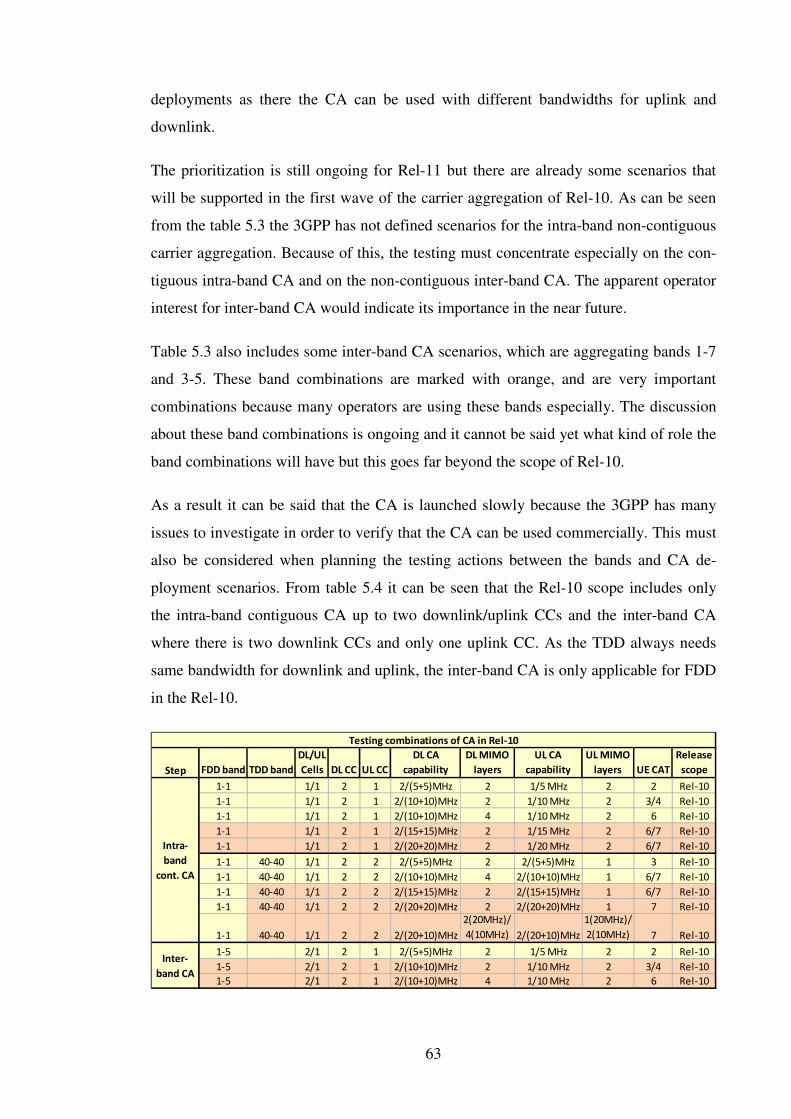
63
deployments as there the CA can be used with different bandwidths for uplink and
downlink.
The prioritization is still ongoing for Rel-11 but there are already some scenarios that
will be supported in the first wave of the carrier aggregation of Rel-10. As can be seen
from the table 5.3 the 3GPP has not defined scenarios for the intra-band non-contiguous
carrier aggregation. Because of this, the testing must concentrate especially on the con-
tiguous intra-band CA and on the non-contiguous inter-band CA. The apparent operator
interest for inter-band CA would indicate its importance in the near future.
Table 5.3 also includes some inter-band CA scenarios, which are aggregating bands 1-7
and 3-5. These band combinations are marked with orange, and are very important
combinations because many operators are using these bands especially. The discussion
about these band combinations is ongoing and it cannot be said yet what kind of role the
band combinations will have but this goes far beyond the scope of Rel-10.
As a result it can be said that the CA is launched slowly because the 3GPP has many
issues to investigate in order to verify that the CA can be used commercially. This must
also be considered when planning the testing actions between the bands and CA de-
ployment scenarios. From table 5.4 it can be seen that the Rel-10 scope includes only
the intra-band contiguous CA up to two downlink/uplink CCs and the inter-band CA
where there is two downlink CCs and only one uplink CC. As the TDD always needs
same bandwidth for downlink and uplink, the inter-band CA is only applicable for FDD
in the Rel-10.
Step FDD band TDD band
DL/UL
Cells DL CC UL CC
DL CA
capability
DL MIMO
layers
UL CA
capability
UL MIMO
layers UE CAT
Release
scope
1-1 1/1 2 1 2/(5+5)MHz 2 1/5 MHz 2 2 Rel-10
1-1 1/1 2 1 2/(10+10)MHz 2 1/10 MHz 2 3/4 Rel-10
1-1 1/1 2 1 2/(10+10)MHz 4 1/10 MHz 2 6 Rel-10
1-1 1/1 2 1 2/(15+15)MHz 2 1/15 MHz 2 6/7 Rel-10
1-1 1/1 2 1 2/(20+20)MHz 2 1/20 MHz 2 6/7 Rel-10
1-1 40-40 1/1 2 2 2/(5+5)MHz 2 2/(5+5)MHz 1 3 Rel-10
1-1 40-40 1/1 2 2 2/(10+10)MHz 4 2/(10+10)MHz 1 6/7 Rel-10
1-1 40-40 1/1 2 2 2/(15+15)MHz 2 2/(15+15)MHz 1 6/7 Rel-10
1-1 40-40 1/1 2 2 2/(20+20)MHz 2 2/(20+20)MHz 1 7 Rel-10
1-1 40-40 1/1 2 2 2/(20+10)MHz
2(20MHz)/
4(10MHz) 2/(20+10)MHz
1(20MHz)/
2(10MHz) 7 Rel-10
1-5 2/1 2 1 2/(5+5)MHz 2 1/5 MHz 2 2 Rel-10
1-5 2/1 2 1 2/(10+10)MHz 2 1/10 MHz 2 3/4 Rel-10
1-5 2/1 2 1 2/(10+10)MHz 4 1/10 MHz 2 6 Rel-10
Intra-
band
cont. CA
Testing combinations of CA in Rel-10
Inter-
band CA

64
Table 5.4: Initial deployment scenarios for Carrier aggregation in downlink (DL) and uplink (UL)
[38, 47].
When considering the physical layer testing steps for different CA deployments in Rel-
10 scope [38], it is relatively clear that the initial testing must concentrate on cases
where the UE uses two downlink CCs and only one uplink CC with the intra-band con-
tiguous CA in FDD. As it was said that intra-band contiguous CA will be used with 30-
40 MHz bandwidths, the testing must be therefore started by combining smaller band-
widths first but the goal is to reach the UE Category 6 or 7 in the commercial networks
by using 30-40 MHz bandwidths on band 1.
As this thesis concentrates on physical layer features, it is good to indicate how the new
CA specific features are used in different stages of CA testing ramp ups. The cross-
carrier scheduling, which is especially used for the interference cancellation, can be
already used in first CA deployments. However, even though it is an optional feature
there are still clearly some interests from the operator side to use the cross-carrier
scheduling at least in some point as the cross-carrier scheduling is a mandatory feature
in Rel-11. The testing aspects of cross-carrier scheduling are discussed more in next
section.
The most important initial testing aspect of CA at the very beginning is obviously the
simultaneous transmission of multiple feedback reporting in CA which will bring totally
new testing scenarios. These issues are discussed more in section 5.1.2.3. The power
control also induces some improvements for the CA by enabling the simultaneous
PUCCH and PUSCH transmission. However, this is an optional feature and does not
have such an impact on the CA when the UE uses only one uplink CC.
After the initial scenarios, the next step in CA is to enable the second uplink CC and
especially to make the inter-band CA to work in FDD mode. It is still a bit unclear how
important the second uplink CC will be on FDD mode and therefore I would concen-
trate the testing on the inter-band CA right after the intra-band CA downlink aggrega-
tion. It is of course clear that the TDD needs the second uplink CC for intra-band CA,
and therefore only the TDD testing must be concentrated on uplink CA and the FDD
testing continues with the inter-band CA. It is seen, that the TDD mode does not have
any interests for inter-band CA and therefore it would be very important to concentrate
the uplink CA testing especially on the TDD. The reason for this is that the TDD spec-

65
trum is not as fragmented as FDD spectrum. This allows aggregating the intra-band
contiguous bandwidths more easily and this way enables even the 40-60 MHz band-
widths. Therefore, there is no need for inter-band CA in TDD mode.
5.1.2.2 Testing of CIF in cross-carrier scheduling
From the physical layer point of view the cross-carrier scheduling is introduced for the
Rel-10 in order to achieve more dynamic grant load balancing among the CCs on a
subframe level and improve the interference. There are many aspects from the R&D
point of view which must be taken into account in testing to verify the cross-carrier
scheduling properly.
As was said in the previous section, it is still a bit unclear how important feature cross-
carrier scheduling will be in the Rel-10 timeframe as it is an optional feature if uplink
CA is not used. The support for this feature is indicated with higher layer parameter
called crossCarrierScheduling-r10 [35]. It is however relatively clear that the cross-
carrier scheduling will come at least with Rel-11 when the uplink CA is enabled, and
therefore the implementation of the feature depends a lot on if operators will start using
this feature already in the Rel-10.
The cross-carrier scheduling is configured for UE with higher layer signaling where the
CrossCarrierSchedulingConfig element carries the cif-Presence-r10 parameter for indi-
cating to the UE if the CIF parameter is present in DCI formats. If this is true, there is
also schedulingCellId-r10 parameter which indicates the serving cell ID which trans-
mits the cross-carrier scheduling allocations and the PCCs [22]. The pdsch-Start param-
eter expresses the starting OFDM symbol of downlink allocations in SCC. The pdsch-
Start parameter varies between bandwidths and must be tested properly with different
bandwidth combinations [4].
From the internal R&D integration testing point of view it is very important to verify
that all the DCI formats including the new parameter and increased bit length are de-
coded properly [17]. Incorrectly coded DCI format will straightly affect the data
throughputs and therefore it is vital, especially in the case of cross-carrier scheduling,
that the UE manages to decode all the DCI formats from the same control region.

66
The internal integration testing must be started with basic CIF functionality. An exam-
ple of such functionality can be seen in figure 5.5 where the CC#1 DCI format does not
contain the cross-carrier indicator as it corresponds to the same component carrier. On
the other hand, for the CC#2 in the same figure 5.5 the CIF value is assumed in the UE-
specific search space because it is used for cross-carrier scheduling [6]. Markedly, this
kind of situation needs to be tested properly, in order to verify the R&D implementation
decodes the different DCI formats correctly. The testing must also pay attention to that
the number of CCs will increase later on and so the UE-specific search space may there-
fore have up to 5 cross-carrier DCI format allocations.
The figure 5.5 also depicts another cross-carrier scheduling search space scenario which
must be tested in order to verify the cross-carrier scheduling implementation. Search
spaces for different CCs may also overlap in some subframes. This can be seen in the
case of CC#3 and CC#4. The UE-specific search space has again two DCI format allo-
cations but these are in this case overlapping each other. In this case the UE must handle
these two search spaces independently by assuming that there is CIF for CC#4 but not
for CC#3 [6]. The internal integration testing must notice that in some cases the UE-
specific and the common search space may overlap in some aggregation level. In this
case testing must verify that the UE monitors the common search space correctly.
Another very interesting testing aspect from the internal R&D integration testing point
of view is the payload size which may be the same for two DCI format allocations if the
CCs have different bandwidths or TMs. In this case it is important to verify that the UE
decodes the DCI formats correctly although the payload is the same in the UE-specific
and common search spaces for different DCI formats. However, this situation occurs
only when the aggregation bandwidths are different.

67
Figure 5.5: Testing aspects of CA search space allocations with cross-carrier scheduling [6].
When the UE does not know which DCI format is used in a particular search space, it
must decode it blindly. From the internal system level testing point of view it is very
important to verify that the UE is able to process a large number of blind decodes in the
case of CA for high performance cases. The number of blind decodes is expected to
increase linearly with the number of configured CCs [4]. For single-carrier operation the
maximum number of blind decodes in any subframe is 44 divided to 12 in the common
search space and 32 in the UE-specific search space. The maximum total number of
blind decodes, which the UE may perform, is 44 for the PCC and 32 for every active
downlink SCCs, so the total may be up to 142 blind decodes in the case of 5 CCs. How-
ever, this is not an issue in the Rel-10 timeframe because the maximum carrier aggrega-
tion count is two on the downlink side. Therefore, the maximum number of blind de-
codes needed is 76 and it should be carefully tested during high performance testing.
5.1.2.3 Simultaneous transmission of multiple feedback reports testing
As it was already said in section 5.1.2.1, the CA has a great impact on the feedback re-
porting because it will increase the number of reports heavily, especially in the case
where the CA is asymmetric between the downlink and uplink. Multiple uplink CCs are
still being specified for Rel-11 and therefore UEs will lack the support for multiple up-
link CA for the time being. Thus, it is very important to concentrate the internal R&D
integration testing on asymmetric CA which includes multiple downlink CCs and only
one uplink CC available. From the testing point of view these aspects bring very inter-
esting use cases which must be tested very carefully in order to verify the UE imple-
mentation.
One of the main issues in the case of asymmetric CA is the HARQ payload size which
will increase dramatically. As a result, the 3GPP has defined the new PUCCH formats,
which were discussed in section 5.1.1.2. When considering the CA testing from
PUCCH format side it is clear that the testing must concentrate first on the 1B because
this format is utilized for up to two CCs which will then be used in the first wave of CA
deployments. The PUCCH format 3 will be used later for over two CC scenarios.
In order to verify the PUCCH format 1B with channel selection, the PUCCH-Config
parameter must be configured via higher layer by using the Rel-8 deltaPUCCH-Shift

68
and nRB-CQI parameters and a new n1PUCCH-AN-CS-List-r10 parameter [22]. The
internal integration testing must be concentrated first on different kinds of combinations
of these parameters in order to verify the basic functionality of PUCCH format 1B. The
PUCCH format 3 testing must be done in a similar way but as this is a totally new for-
mat, the 3GPP has defined the parameters format3-r10 and n3PUCCH-AN-List-r10
which must also be verified together with different Rel-8 parameter configurations
which will give different timing shifts and CQI space allocations. It should be noted that
the PUCCH format 3 can only be used in a case where at least two antenna ports are
used for PUCCH. Because of this, the PUCCH format 3 testing can be postponed as the
3GPP has defined the two-AntennaPortsForPUCCH-r10 parameter [35] for transmit
diversity and therefore UE must support this parameter before the PUCCH format 3
feature.
As already mentioned in section 5.1.1.2., it is difficult to get all the periodic CSI reports
to fit in the uplink data in the case of asymmetric CA. The 3GPP has defined the priori-
tization of CSI reports which were shown in the table 5.1. From the CA internal integra-
tion testing point of view this prioritization must be tested properly in the cases where
multiple downlink CCs CSI reports are transmitted in a single uplink CC to verify that
the prioritization works. The different downlink CCs are configured from the higher
layer so that different types of collisions are tested and the prioritization order is veri-
fied. From the single uplink CC point of view there are no new configuration parame-
ters for aperiodic or periodic CSI reporting if transmission modes 1 - 8 are used. The
TM9 brings new aspects to CSI testing but these are discussed more in section 5.2.4.
The aperiodic CSI feedback is transmitted to a set of CCs which are stated in CQI re-
quest parameter in DCI format 0 or 4. However, as was stated already in section 5.1.2.1,
the Rel-10 UEs will only use one uplink serving cell. Therefore, the CSI request param-
eter can only have values 00 or 01 as was shown in table 5.2. These are basically the
same values which have already been used in Rel-8 with CQI request and therefore the
values do not bring any new testing aspects to the internal integration testing. In the
Rel-11 timeframe the CSI triggering will bring more interesting testing aspects as then
the CSI request parameter values 10 and 11 are possible.
The collisions are also possible between periodic CSI and aperiodic CSI for the same or
different downlink CCs. In this case the periodic CSI is dropped and only the aperiodic

69
CSI feedback is transmitted. This applies even if the periodic and aperiodic CCs are for
different downlink CCs. However, this does not bring any new internal integration test-
ing aspects compared to the Rel-8 as the periodic and aperiodic CSI collisions are pos-
sible also there even though collisions are rarer. Therefore, this can be seen rather as a
regression testing for the CSI collisions as there might be more collisions in the case of
CA.
The above analyze focused on transmission of HARQ or CSI reports alone. It is obvious
that in the real life network these two reporting types are used at the same time and thus
the simultaneous utilizations must be system tested very carefully in order to achieve
the full maturity for the UE in R&D level and later on in the conformance testing. From
the physical layer internal R&D system testing point of view there is also the SR which
must be taken into account from collision point of view although the SR does not affect
the Rel-10 CA.
From the internal integration testing point of view, the UE tries to avoid these collisions
by transmitting the reports in separate channels in the case of collision. However, as the
collisions between the HARQ and periodic CSI reports are very obvious, the 3GPP has
defined the simultaneousAckNackAndCQI higher layer parameter to clarify the collision
procedure [22]. When this parameter is set to ‘1’ in FDD mode, the UE must be able to
multiplex the periodic CSI report with HARQ report. On the other hand, if the parame-
ter is set to be ‘0’, the UE must drop the CSI report all together. However, this feature is
behind the Rel-8 FGI bit 2 which is not mandatory in Rel-10 and therefore the integra-
tion testing of this feature can be postponed. The TDD uses the same procedures to
avoid the collisions, although the collisions are more common on TDD side because the
number of uplink subframes may be restricted in some TDD subframe configurations.
There is also some other testing aspects in case there is more than one uplink serving
cell but these aspects must be investigated more in the upcoming Rel-11.
From the HARQ point of view, it is important to verify in internal system level testing
that the UE is capable of transmitting the HARQ acknowledgement and RS in the same
subframe. The PUCCH format 1B does not support this so the testing can commence
only after implementing PUCCH format 3.
It is rarer that UE sends the periodic CSI report and SR at the same time because this
can be avoided with proper eNB configuration. However, from the internal system level

70
testing point of view it cannot be said that this is not a valid case and therefore it must
be tested. In the case of simultaneous periodic CSI report and SR, the UE is forced to
drop the CSI report and transmit the SR only [17]. The SR is very critical to the uplink
transmission as it controls the uplink data transmissions and therefore it has to be
transmitted to the eNB.
The next scenario, where the UE transmits the HARQ acknowledgement, periodic CSI
report and SR simultaneously to the eNB is very similar to the previous situation. How-
ever, this situation is valid only if the UE supports the FGI bit 2 which was used to re-
strict the simultaneous periodic CSI and HARQ. Therefore, this case can be postponed
until the FGI bit 2 has been implemented and supported. In this case the CSI report is
dropped and the HARQ is multiplexed with the SR. It must be verified that the multi-
plexed subframe is received correctly by the eNB. Because the HARQ and SR multi-
plexing are valid only in the case of PUCCH format 3, this case does not apply with
PUCCH format 1B. So as a conclusion, this case has many restricted features, and
therefore it cannot be implemented fully before Rel-11.
5.1.2.4 Testing of power headroom in the case of CA
As it was said in section 5.1.2.1, the inter-band uplink CCs are only possible in Rel-11.
Therefore, the testing must be concentrated on the intra-band uplink CCs where the UE
can have two uplink CCs for one serving cell. In the case of one uplink CC, the Rel-8
power configuration is re-used. When the UE is configured for the multiple uplink CCs,
the extended PHR is configured for MAC layer by configuring the MAC-MainConfig
parameter with extendedPHR-r10 parameter via higher layer [22, 26]. The extended
PHR MAC control element can indicate the PHR for both PCell and SCell [22]. Also
the PHR reporting type 1 or 2 is indicated. If the PHR reporting type 2 is used, the sim-
ultaneous PUCCH and PUSCH configuration is indicated in PUCCH-Config with
simultaneousPUCCH-PUSCH-r10 parameter.
From the internal physical layer integration testing point of view, the type 1 PHR re-
porting is mandatory for Rel-10. Therefore, the initial integration testing must be con-
centrated on the type 1 for the correct PHR calculation in UE and this way to verify that
the PUCCH and PUSCH transmission powers are calculated correctly in UE for all up-
link CCs. In the case of uplink CA the path-loss is important for the uplink transmission

71
and this must also be considered in testing. As it was stated in section 5.1.1.3, it is espe-
cially important to verify that the new path-loss reference is correctly calculated for the
SCC in order to verify that the SCell transmission powers are calculated correctly. As
the maximum power is still the same for the UE, it must also be system tested carefully
that the power is shared between the uplink CCs correctly although the channel condi-
tions may be different for each of the uplink CCs.
The type 2 PHR reporting uses the simultaneous PUCCH and PUSCH transmission and
is an optional feature for Rel-10. From the internal integration testing point of view,
however, there are some very important testing aspects which must be tested properly in
order to verify the simultaneous PUSCH and PUCCH transmission. In the case of sim-
ultaneous PUCCH and PUSCH, integration testing must be concentrated on the right
power limitation between the PUCCH and PUSCH as was discussed earlier. The power
is scaled according to the content of the PUSCH or PUCCH and therefore different
power levels must be system tested properly in order to verify that the UCI is transmit-
ted correctly between the PUSCH and PUCCH. In some cases the power scaling may
even adjust the power to zero in either of the channels. When using the type 2 PHR re-
porting, there might also be situations where in some subframes the PUCCH is not actu-
ally transmitted. Therefore these cases must be system tested properly in order to verify
that the UE can use the so called hypothetical PUCCH format 1A in PHR reporting. In
conclusion, the type 2 PHR brings many difficult testing aspects to both integration and
system level testing. Therefore, the internal testing aspects must be carefully analyzed in
order to meet the conformance test case requirements when using simultaneous PUCCH
and PUSCH transmission.
5.1.2.5 Conformance and field testing for CA
From the conformance testing point of view it is obvious that CA will have a great im-
pact on the conformance testing and hence this must be taken into account already in
R&D integration and system level testing in order to meet the 3GPP demands for the
CA. The 3GPP still has some of the Rel-10 RAN5 specifications ongoing but as can be
seen from the RAN4 specification the CA will extend the RF performance cases and
bring totally new cases for RRM testing [41]. Before going into the details of CA con-
formance cases, the 3GPP has defined aggregation combinations and CA classes for
Rel-10 which will be used in conformance testing of CA. These CA combinations must

72
be considered already in internal R&D integration testing in order to meet the 3GPP
demands for CA in conformance testing [20].
As can be seen from table 5.5. the 3GPP has defined classes for CA in order to limit the
component carriers. At this point, the 3GPP has defined classes A, B and C where the
CA has been limited to two component carriers and to 40MHz bandwidth [20]. The first
CA scenarios that have been defined by 3GPP are showed in table 5.6. It can be seen
that the CA conformance testing must be started with Band 1 and with combinations of
15MHz + 15MHz and 20MHz + 20MHz scenarios in the case of FDD. In the TDD case
the conformance testing must be concentrated on cases where the CA uses combinations
of 10MHz + 10MHz, 15MHz + 15MHz, and 20MHz + 20MHz.
Table 5.5: Carrier aggregation classes [20].
The inter-band scenarios have one initial scenario already completed and this must be
noticed when the inter-band R&D integration testing is started. As can be seen from
table 5.6. the inter-band scenario uses bands 1 and 5 with class A. With class A the ag-
gregation is limited to Band 1 and 5 on the 10MHz bandwidth.
Table 5.6: First CA deployments scenarios [20].
The CA conformance test cases are still under discussion in RAN5 specification group
but from some work items it can be seen what kind of test cases they are discussing at
the moment and what kind of cases there will be. The main subjects were introduced in
work item R5-112447 [41] where it was decided that from the higher layer point of
view the cases must include at least basic SCell addition/release and some SCell modi-
Channel Aggregation
Bandwidth Classes
Aggregated Transmission
BW Configuration
Number of
Component Carriers
A ≤100 (max 20MHz) 1
B ≤100 (max 20MHz) 2
C 100-200 (20-40MHz) 2
D,E,F Under Study Under Study
Intra-band contiguous Carrier Aggregation
Band Class 1.4MHz 3MHz 5MHz 10MHz 15MHz 20MHz Mode
1 C x x FDD
40 C x x x TDD
Inter-band non-contiguous Carrier Aggregation
Bands Class 1.4MHz 3MHz 5MHz 10MHz 15MHz 20MHz Mode
1 - 5 A x FDD

73
fications. Also, the new neighboring measurement event called A6, which is related to
the SCell is included into the conformance test cases.
From the physical layer point of view, the most interesting conformance test cases are
related to the activation and deactivation of SCell. Also features like PDCCH monitor-
ing toggling for the SCell is planned. These were already discussed in the basic internal
R&D integration testing in section 5.1.2.2, and it can be seen that these have an effect
on the conformance test cases as well. There will in addition be cases which test the
CQI/PMI/RI reporting for the SCell, and therefore it is important to verify these features
already in the R&D integration phase.
When considering the conformance test case specification 36.521-1 [21], it can be seen
that RF performance cases are extended to support CA. The test cases are the same as
were already used in Rel-8 but the test limitations have been extended to include the CA
cases. These cases include for example the TX-RX frequency separation in the case of
PCC and SCC, and spurious response in the case of CA. However, the CA cases con-
centrate more on the intra-band CA, and the inter-band testing is mainly postponed into
the Rel-11 conformance testing. It can be seen that the 3GPP also considers totally new
requirements and cases for RF performance, like receiver image cases.
From the RRM point of view, the conformance testing in 36.521-3 will have greater
impact on the CA because it has so many new features which are affecting the UEs. The
main cases have already been decided but the main parameters for the cases are still
pending. From the R4-114849 [44] it can be seen that the testing is concentrated on the
radio link monitoring, Intra-/Inter-/RAT- measurements and measurement accuracy.
3GPP has also decided that the CA cases are released in two phases. The first phase will
include cases where the SCell is deactivated and the UE makes event based measure-
ments with A2 and A6 reporting modes. The phase one also includes measurement ac-
curacy tests where UE is measured with absolute and relative Reference Signal Received
Power (RSRP) and Reference Signal Received Quality (RSRQ) accuracy.
In second the phase the cases are extended so that the event based measurement report-
ing happens with PCell interruption. Also new OTDOA based RSTD measurement cas-
es are introduced where the first two cases are concentrating on the reporting delay cas-
es and two other cases on RSTD accuracy. However, these are very similar to the initial

74
OTDOA conformance test cases in section 4.2.3.1 and therefore the only new thing here
is to verify that the OTDOA works with CA. Every case uses three intra-frequency cells
with 10MHz bandwidths. Also different kinds of Additive White Gaussian Noise
(AWGN) channel modes are configured to simulate better real life conditions.
It is very important to simulate different kinds of test cases where the OTDOA based
positioning reference signals are configured with different kinds of measurements in CA
scenarios already in the internal R&D integration and system level testing. This will
speed up the certification process and help to pass all the RRM cases more easily.
Carrier aggregation has been studied a lot during the last few years in order to evaluate
the CA deployments in real life scenarios. From the physical layer point of view, the
most interesting field test aspect is obviously the throughput testing and this way to ver-
ify the UE behavior in different channel conditions. CA is very challenging for the RF
design and this must be taken into account when planning the field tests.
If the RF baseband cannot handle the incoming or outgoing frequencies properly it will
straight affect the physical layer by increasing the Block Error Rate (BLER). Now if the
UE uses the cross-carrier scheduling for downlink CA it will have a great impact
straight on the data throughputs. This is because if UE has lost the CC where the
PDCCH for several carriers were transmitted, the data from all the carriers are lost even
though these were received correctly.
The same problem also affects the uplink because in the case of asymmetric CA one
uplink CC will carry the multiple feedback reports for several downlink CCs. If this
uplink CC is lost, the feedback reports for several downlink CCs will as well be lost.
This will increase uplink overhead as well as lower the uplink and downlink data
throughputs.
In order to verify these kinds of situations from the physical layer point of view, the
field test scenarios must have especially difficult CA cases regarding to the RF. These
aspects are discussed in [42] where the Doppler frequency shift has an impact particu-
larly on CA guard band and this way on the BLER. Because of this the field tests must
concentrate also on the physical movement speed of the UE. When adding the cell-edge
interference and different channel propagation issues to the scenario, it is important to

75
verify that the power consumption and the DL/UL data throughputs stay on an accepta-
ble level.
The CA interface between CCs is also discussed in [43], where the simulations show
clearly that if the guard band is too small, the interference will increase heavily. There-
fore, it is very important to pay attention to these issues and verify that there are no
blocking issues related to the interference when starting the field testing with CA ena-
bled UEs. 3GPP is as well aware of the interface issues between CCs, and therefore it is
one of the main blocking issues between several intra- and inter-band combinations at
the moment [43].
5.2 Downlink multi-antenna transmission enhancements
In the Rel-10, the downlink spatial multiplexing scheme is extended to support up to
eight streams by using 8x8 MIMO multi-antenna techniques. Similarly to Rel-9, the
scheme is based on the same UE-specific RSs, but is in this case optimized for both
FDD and TDD. The UE-specific RSs have been extended up to eight layers in order to
support eight data streams simultaneously. The reason for enhancing the UE-specific
RS in LTE-Advanced is due to overhead which the Cell-specific RSs are causing in the
case of eight layer transmission [13]. UE-specific RSs are more easily adaptable to the
number of layers of data transmission and the size of the resource allocation. However,
there are problems especially with the FDD case when the UE uses UE-specific RSs.
Therefore, to support CQI and to compute channel spatial information for up to eight
layers, an additional reference signal called Channel State Information Reference Signal
(CSI-RS) is introduced. The CSI-RS is transmitted sparsely in order to reduce the over-
head in the transmission with eight layers.
5.2.1 Rel-10 enhanced downlink reference signals
In order to prevent the reference signal overhead and to keep the backward compatibil-
ity, the 3GPP decided to extend the Rel-9 UE-specific RS structure and introduce a new
CSI-RS symbol structure. Both reference signals have an important role in transmission
because the UE-specific RS is used for data demodulation on eNB side and in addition
the CSI-RS helps the eNB to estimate the channel quality.
76
5.2.1.1 Rel-10 UE-specific RS for demodulation
As was earlier discussed in section 4.1.1, the UE-specific RS structure was redesigned
in Rel-9. It was relatively clear at the time of Rel-9 that the LTE radio-access should be
further extended to support up to eight layer spatial multiplexing in Rel-10 [4]. There-
fore, the Rel-10 UE-specific RS structure is straightforward extension of Rel-9 to sup-
port up to eight simultaneous UE-specific RSs. From the MU-MIMO point of view, the
Rel-10 UE-specific RS also supports up to four different users. This has been done by
extending the orthogonal cover code from two to four.
In order to ensure backward compatibility, the UE-specific RS pattern for up to two
layer transmission is same to that already defined in Rel-9. The UE-specific RSs are
frequency multiplexed in groups of four RSs, as can be seen from figure 5.6. Each
group is separated by means of mutually orthogonal patterns, as was already discussed
with Rel-9. However, in this case there are now up to 24 reference symbols within a
resource block pair. In the case of eight layer transmission, the UE uses antenna ports 7-
14 for UE-specific RSs [15].
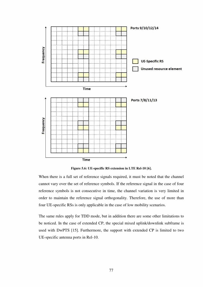
77
Figure 5.6: UE-specific RS extension in LTE Rel-10 [6].
When there is a full set of reference signals required, it must be noted that the channel
cannot vary over the set of reference symbols. If the reference signal in the case of four
reference symbols is not consecutive in time, the channel variation is very limited in
order to maintain the reference signal orthogonality. Therefore, the use of more than
four UE-specific RSs is only applicable in the case of low mobility scenarios.
The same rules apply for TDD mode, but in addition there are some other limitations to
be noticed. In the case of extended CP, the special mixed uplink/downlink subframe is
used with DwPTS [15]. Furthermore, the support with extended CP is limited to two
UE-specific antenna ports in Rel-10.

78
5.2.1.2 Channel state information RS - CSI-RS
The main goal of the CSI-RSs is to obtain channel state feedback for up to eight trans-
mit antenna ports to assist the eNB in its precoding operations. The CSI-RSs were de-
signed in Rel-10 to support transmission in 1, 2, 4 and 8 antenna ports [4]. The used
antenna ports are 15, 15 and 16, 15 to 18, and 15 to 22 [13].
The CSI-RS is quite rare in time and frequency because the requirements for CSI meas-
urements are not as restrictive as for the UE-specific RS. It is typically transmitted peri-
odically with very low density, only 1 RE/port/PRB [4]. The periodicity of CSI-RS is
configurable with duty cycle values ranging from 5ms to 80ms. This is especially useful
in the case where downlink MIMO enhancements are targeting to work in low-mobile
scenarios. This means that the impact on Rel-8 and Rel-9 UEs is limited only to the
subframes where the CSI-RSs are transmitted. However, the weight of the CSI-RS al-
lows for transmission of data to Rel-8 UEs in subframes with CSI-RS as well, although
with lowered performance. In this case the MCS should be downscaled according to the
additional interference [17]. In practice however, the eNB does not transmit any
PDSCH allocations in these REs and should map the remaining PDSCH symbols in line
with Rel-8.
The main purpose of CSI-RS is to support eight antennas transmission at the eNB side.
However, the CSI-RS patterns are defined for other antenna configurations as well, as
can be seen from figure 5.7 [6]. The patterns are very flexible and the pattern for low
number of antenna ports is a subset of the pattern for a higher number of antenna ports.
Same pattern can also be used for both FDD and TDD mode [15]. However, with TDD
the collision with TM7 and antenna port 5 must be avoided. Used pattern is signaled to
the UE through higher signaling. Compared to the Cell-specific RS, the CSI-RS has
higher reuse factor in patterns. This helps especially in network planning and the colli-
sions between CSI-RS are avoided easily.
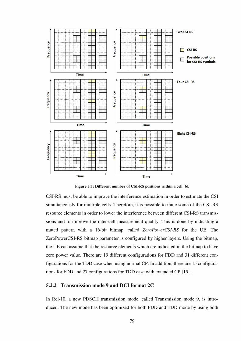
79
Figure 5.7: Different number of CSI-RS positions within a cell [6].
CSI-RS must be able to improve the interference estimation in order to estimate the CSI
simultaneously for multiple cells. Therefore, it is possible to mute some of the CSI-RS
resource elements in order to lower the interference between different CSI-RS transmis-
sions and to improve the inter-cell measurement quality. This is done by indicating a
muted pattern with a 16-bit bitmap, called ZeroPowerCSI-RS for the UE. The
ZeroPowerCSI-RS bitmap parameter is configured by higher layers. Using the bitmap,
the UE can assume that the resource elements which are indicated in the bitmap to have
zero power value. There are 19 different configurations for FDD and 31 different con-
figurations for the TDD case when using normal CP. In addition, there are 15 configura-
tions for FDD and 27 configurations for TDD case with extended CP [15].
5.2.2 Transmission mode 9 and DCI format 2C
In Rel-10, a new PDSCH transmission mode, called Transmission mode 9, is intro-
duced. The new mode has been optimized for both FDD and TDD mode by using both

80
UE-specific and CSI reference signals [6]. The TM9 is very similar to the TM8 but it
has some extensions in order to achieve even higher data rates and to improve the MU-
MIMO operations.
The maximum number of codewords or transport blocks transmitted over eight layers
will remain two, with support for separate modulation and coding schemes between
codewords [4]. Because the rank number is increased, the new codeword to layer map-
ping for layers 5 to 8 is showed in figure 5.8. The codeword to layer mapping in the
case of 4 antenna ports stays as it was designed in Rel-8 in order to keep the backward
compatibility. Layer 1 to 4 mapping was shown in figure 2.8. Like TM8, the TM9 sup-
ports dynamic switching between SU-MIMO and MU-MIMO when the used data
streams vary between time slots. The MU-MIMO has been increased to support 4 sim-
ultaneous users. From the UE point of view, the MU-MIMO operation is still transpar-
ent so no signaling is provided to inform UEs of the presence of co-scheduled transmis-
sions.
Figure 5.8: Codeword to layer mapping for up to 8 antenna ports [4].
From the physical layer point of view of the TM9, a new DCI format 2C is introduced
[16]. This new DCI format is based on format 2B which was used in TM8. However,
the DCI format 2C has some improvements in order to support MU-MIMO operations
better. With this format, the TM9 can support dynamic switching between SU-MIMO
transmission up to rank 8 and MU-MIMO transmission up to rank 4. This has been done
by increasing the scrambling identity bit with two bits. This new 3 bit long Scrambling
Identity (SCID) parameter is reused to encode the number of layers, antenna port map-
ping and UE-specific RS SCID jointly. The encoding can be seen in table 5.7. The val-
ues 4-6 for single codeword enabled are only supported in the case of SU-MIMO re-
transmissions. Of course, it is assumed that transport block has previously been trans-
mitted using two, three or four layers. Hence, for transmission with one codeword and
two layers, only one scrambling sequence is used.
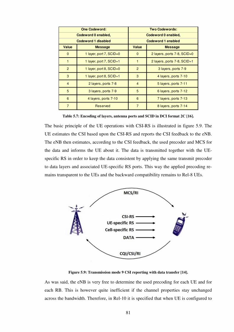
81
Table 5.7: Encoding of layers, antenna ports and SCID in DCI format 2C [16].
The basic principle of the UE operations with CSI-RS is illustrated in figure 5.9. The
UE estimates the CSI based upon the CSI-RS and reports the CSI feedback to the eNB.
The eNB then estimates, according to the CSI feedback, the used precoder and MCS for
the data and informs the UE about it. The data is transmitted together with the UE-
specific RS in order to keep the data consistent by applying the same transmit precoder
to data layers and associated UE-specific RS ports. This way the applied precoding re-
mains transparent to the UEs and the backward compatibility remains to Rel-8 UEs.
Figure 5.9: Transmission mode 9 CSI reporting with data transfer [14].
As was said, the eNB is very free to determine the used precoding for each UE and for
each RB. This is however quite inefficient if the channel properties stay unchanged
across the bandwidth. Therefore, in Rel-10 it is specified that when UE is configured to
Value Message Value Message
0 1 layer, port 7, SCID=0 0 2 layers, ports 7-8, SCID=0
1 1 layer, port 7, SCID=1 1 2 layers, ports 7-8, SCID=1
2 1 layer, port 8, SCID=0 2 3 layers, ports 7-9
3 1 layer, port 8, SCID=1 3 4 layers, ports 7-10
4 2 layers, ports 7-8 4 5 layers, ports 7-11
5 3 layers, ports 7-9 5 6 layers, ports 7-12
6 4 layers, ports 7-10 6 7 layers, ports 7-13
7 Reserved 7 8 layers, ports 7-14
One Codeword:
Codeword 0 enabled,
Codeword 1 disabled
Two Codewords:
Codeword 0 enabled,
Codeword 1 enabled

82
feedback PMI, it can assume that the precoder is the same across all RBs within the
Precoding Resource Block Group (PRG) which is called PRB bundling [4]. When the
UE is configured to feedback for example the subband PMIs, the eNB can assume to
use the same PMI across the RBs in a subband. The defined PRG sizes are illustrated in
table 5.8.
Table 5.8: PRG sizes [4].
5.2.3 Enhanced CSI feedback
In order to achieve better system capacity in MU-MIMO, the accuracy of the CSI feed-
back from the UEs is a key factor to improve the MU-MIMO operations [13]. There-
fore, an improved feedback was designed in the Rel-10.
The Rel-10 introduces a possibility to use eight simultaneous antenna ports for down-
link MIMO transmission [4]. In order to realize the potential benefits and gains from
this modification, a need for a new codebook was obvious. The new codebook aims to
provide even more accurate channel state information to the eNB. In the case of TDD,
channel reciprocity and SRS symbols can be used for obtaining the CSI by estimating it
from the uplink transmission. With FDD the case is trickier. The channel conditions
may vary from fast fading (short-term properties) to slow fading (long-term properties),
and the true CSI lies between these two levels. Hence, a need for more specific CSI
feedback mechanisms emerged in the 3GPP.
Long-term channel properties do not change rapidly from one CSI measurement in-
stance to another. Because of this, it makes sense to separate channel state properties
into a long-term and wideband part, and a short-term and narrowband part. When taking
into account these different channel conditions, an efficient feedback signaling com-
pression is achieved by decoupling the long- and short-term CSI components. The
3GPP introduced a double codebook structure for Rel-10 CSI feedbacks to support
downlink MIMO with eight transmit antennas [14].
System BW/number of RBs Subband size PRG size
1
2
3
2
<10
11 - 26
27 - 63
64 - 110
4
4
6
8

83
The key principle for the new codebook is to produce a precoder matrix W which is
constructed from two different codebooks, illustrated in figure 5.10. W1 targets the
long-term wideband channel properties while W2 aims at short-term frequency selective
CSI properties. The resulting precoder matrix is calculated as the matrix multiplication
of W1 and W2 [4].
Figure 5.10: Double codebook principle: W1, targets long-term channel properties, and W2, short-
term channel properties [14].
It should be noticed that the newly defined double codebook is only applicable in the
case of 8 TX antennas. For 2 TX and 4 TX antennas the Rel-10 codebooks remain un-
changed and are the corresponding to the codebooks of Rel-8 [15]. The double code-
book concept in the case of the 8 TX antennas is mainly considered attractive for lower
layer ranks, namely ranks 1-2 and also ranks 3-4. It as well depends a lot on the spatial
correlation of the channel.
When considering the TM9 CQI feedback reporting, it can be seen from the table 5.9,
that the TM9 supports the same aperiodic and periodic CQI reports as the TM8 [4].
However, some of the modes have been extended in order to take advantage of the new
two-stage PMI feedback codebook structure.
Table 5.9: Transmission mode 9 CQI feedback modes [6].
Both aperiodic and periodic CQI modes have been extended in order to support 8 TX
transmissions. These two-stage codebook extensions are affecting both wideband and
84
subband RI/PMI/CQI reporting. From the aperiodic point of view, the reporting modes
1-2, 2-2 and 3-1 on PUSCH are extended to use precoders W1 and W2 in order to take
advantage of the new two-stage PMI feedback codebook structure.
From the periodic CQI feedback point of view, the 3GPP has defined a new one bit PTI
report which is added to the RI reports so that the UE can handle the divided content of
reports. This brings some very interesting aspects to the 8 TX testing which are dis-
cussed more in section 5.2.4.3. In addition to the PTI value, the 3GPP has defined new
submodes for the CQI mode 1-1 reporting. These two submodes are used to carry two
separate types of PUCCH feedback reports by dividing the RI, CQI and PMI reports
into two separate reports. The aim of using the submode 1 is to avoid the subsampling
which is used in submode 2. The subsampling is discussed more in section 5.2.4.3, and
it will also bring some very interesting testing aspects for TM9.
5.2.4 Testing of transmission mode 9 and downlink MIMO enhancements
One of the key testing aspects of TM9 is the FDD beamforming which was already in-
troduced in TM8 but it had some problems with the channel reciprocity overhead. This
problem has been corrected by introducing the new CSI-RS to lower the overhead and
therefore especially FDD operators are very interested in skipping the TM8 and in going
straight to the TM9. Because of this the testing must especially concentrate on the FDD
TM9 SU-MIMO cases.
The testing must also concentrate on the TM9 MU-MIMO cases because it has been
shown in [14] that the 4x4 MU-MIMO with TM9 scenarios can increase the network
capacity compared to the Rel-8 MU-MIMO cases. The bits per Hz ratio increases to
about 4,3 bps/Hz in TM9 4x4 MU-MIMO. In TM5, this is only 2,3 bsp/Hz. When com-
paring these to the SU-MIMO case in Rel-8/10 the ratio in 4x4 case is about 3,9 bsp/Hz.
In cell-edge cases the bits per Hz ratio will be even greater when comparing the MU-
MIMO cases between Rel-10 and Rel-8. This is the reason why the MU-MIMO is not
so used in Rel-8 but in the Rel-10 it will have a major role to increase the network ca-
pacity [14].
The TM9 physical layer internal R&D integration testing must be started with basic
SIMO and MIMO cases where the maximum is the 4x2 MIMO, because the 8 TX an-
tenna is optional feature for the UE if it is not a category 8 UE. The UE category is indi-

85
cated to the network with physical layer parameter tm9-With-8Tx-FDD-r10 in the case
of FDD and with FGI Rel-10 bit 104 in the case of TDD [22, 35]. Therefore, the testing
of TM9 must at first be concentrated on 2 TX and 4 TX antenna cases. In UE capability
info there is also FGI bit 103 which restricts the TM9 transmission to 2 CSI-RS. There-
fore, the testing must be started first with rank 2 TM9 in order to meet the basic func-
tionality of Rel-10. There are in addition FGI bits for TM9 CQI modes similar to those
already defined in Rel-8/9 and this will be discussed later in section 5.2.4.3.
5.2.4.1 CSI-RS testing aspects
Before going to the TM9 testing itself, it is clear that the new CSI-RS must also be test-
ed carefully in order to achieve proper channel quality information. The CSI-RS is con-
figured on higher layer by indicating the configuration in CSI-RS-Config element. The
internal integration testing must first be concentrate on the one or two antenna transmis-
sions which are indicated with antennaPortsCount-r10 parameter. As was already said
the support for four or eight antenna transmission is behind the FGI bits. Every CSI-RS
subframe configuration must be tested carefully in order to verify that the right CSI-RS
periodicity is achieved. There is also a parameter called resourceConfig-r10. This pa-
rameter is used for mapping the CSI-RS for right antenna configurations, and it is used
especially in the case of MU-MIMO.
It looks like that the TM9 will be the breakthrough for the MU-MIMO in the case of
FDD, because the TM5 is restricted with FGI bit in all LTE releases, and therefore it is
postponed widely. It is shown in [14] that the TM9 MU-MIMO has a higher bit per Hz
ratio, and therefore operators will start deploying the MU-MIMO. Hence, it is recom-
mended focusing on MU-MIMO testing aspects already in internal integration testing
phase.
In addition, there is configuration parameter zeroTxPowerSubframeConfig which is
used to mute the CSI-RS transmission. This feature is very important especially for
lowering the interference between the CSI-RS transmissions. The muting can use the
same subframe configurations which were defined for the basic CSI-RS subframe con-
figuration parameter. This will bring very interesting testing combinations in internal
system level testing if the parameters are using very similar configurations. The 3GPP
has also defined a parameter, called zeroTxPowerResourceConfigList-r10 which can be

86
used for muting only some of the periodical CSI-RS transmissions. The muted
subframes are given in a bit string which is used as a mask to restrict some of the CSI-
RS transmissions. This parameter must be tested carefully in order to verify that the UE
still sends the right CSI-RS transmissions which are not restricted by this mask. The
muting helps especially in the case of CA where there will be multiple CSI-RS trans-
missions.
Table 5.10: CSI-RS subframe configurations [15].
5.2.4.2 Multi-layer beamforming and testing of DCI format 2C
The testing of TM9 must be started by verifying the old DCI format 1A in the case of
TM9 and of course also verifying the new DCI format 2C. Both formats must be tested
with all bandwidth variations from 1.4MHz to 20MHz. The normal and extended CP
must be considered in internal integration testing with different modulation and coding
schemes. Similarly to the DCI format 2B in TM8, the format 2C does not support dis-
tributed VRB allocations, and therefore distributed transmission tests can be avoided in
the integration testing. DCI format 1A testing is very similar to that already planned in
TM8 and therefore the plan can be reused in the TM9 case. However, when planning
the DCI format 2C testing there are some new cases which must be noticed in order to
achieve the 8 TX transmissions.
The DCI format 2C is like the DCI format 2B. Therefore, integration testing for differ-
ent transport blocks is very similar to different modulation and coding schemes in order
to verify that the UE can handle the TB to codeword mapping with different layer con-
figurations. However, the TM9 supports up to 8 layer transmission, and this must be
taken into account properly in testing. As was already said, the 8 TX MIMO is optional
if the UE does not support category 8. The internal integration testing must first be con-
centrated on the SU-MIMO 2 TX and 4 TX cases and also on the MU-MIMO cases
where only one or two layers are in use depending on the number of UEs.
CSI-RS-SubframeConfig
(configuration index)CSI-RS periodicity CSI-RS subframe offset
0 – 4 5
5 – 14 10
15 – 34 20
35 – 74 40
75 – 154 80
RSCSI−I
5RSCSI −−
I
15RSCSI −−
I
35RSCSI −−
I
75RSCSI −−
I

87
The 1-layer cases are enabled by using the new scrambling identity indication in DCI
format 2C as was shown in table 5.7 in section 5.2.2. It is important to test all the avail-
able combinations of 1-layer configurations by using values 0-3 from table 5.7, when
only one codeword is enabled. From the MU-MIMO point of view, it is also very im-
portant to verify in integration testing that the different codeword combinations are test-
ed properly in order to verify that the UE observes the right channel/TB. This must be
tested so that different scrambling bits are used with different codeword configurations
by setting the redundancy version bit to ´1´ in DCI format 2C for codeword which must
be followed and by setting the other redundancy bit to ‘0’. This is as a very important
testing step in order to meet the different deployment scenarios in conformance testing.
The 2-layer cases are very similar to the 1-layer cases. The scrambling bit must also be
tested very precisely in order to verify different deployment scenarios. For 2-layer cases
the scrambling bit can have values 0 or 1 in the case where both codewords are enabled.
Both scrambling bit combinations must be tested because in the case of 2-layer MU-
MIMO, the network can assign either of these values to the UE. Also, in the case of
retransmission, it must be verified in internal integration testing that the UE is able to
use the scrambling bit 4 with only one codeword enabled. In this case it is important to
test the retransmission of both codewords by moving the transport block so that the
right codeword is used for retransmission.
When the UE supports up to 4-layer spatial multiplexing with 4-by-4 transmissions, the
integration testing must be extended to include also the 3-layer and 4-layer transmis-
sions and retransmissions. In addition all the 1-layer and 2-layer cases must be retested
with 4 TX cases. Fast rank adaptation must be considered as the network can change the
UE´s assigned rank dynamically by changing the rank between the SU-MIMO and MU-
MIMO very rapidly although the MU-MIMO is not seen by the UE.
The internal integration testing extends even more when the UE supports the 8-by-8
spatial multiplexing and as a consequence the UE can use up to 8-layer transmissions.
In that case the testing of scrambling bit with values 4-7 becomes essential and the UE
must be verified to use the 5-, 6-, 7-, and 8-layer transmissions correctly with different
bandwidths and modulation and coding schemes when two codewords are enabled. As it
was stated earlier, the 8 TX transmissions are highly dependent on the spatial correla-
tion of channel. This might lead to the fact that the operators will use namely the ranks
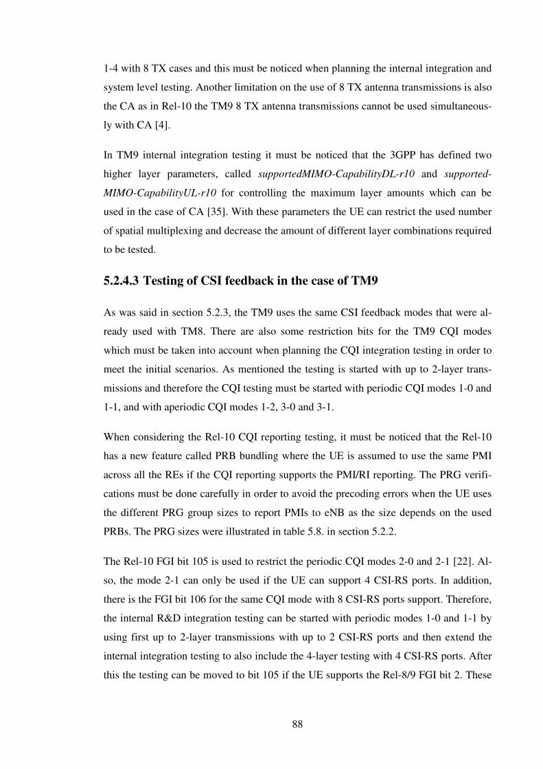
88
1-4 with 8 TX cases and this must be noticed when planning the internal integration and
system level testing. Another limitation on the use of 8 TX antenna transmissions is also
the CA as in Rel-10 the TM9 8 TX antenna transmissions cannot be used simultaneous-
ly with CA [4].
In TM9 internal integration testing it must be noticed that the 3GPP has defined two
higher layer parameters, called supportedMIMO-CapabilityDL-r10 and supported-
MIMO-CapabilityUL-r10 for controlling the maximum layer amounts which can be
used in the case of CA [35]. With these parameters the UE can restrict the used number
of spatial multiplexing and decrease the amount of different layer combinations required
to be tested.
5.2.4.3 Testing of CSI feedback in the case of TM9
As was said in section 5.2.3, the TM9 uses the same CSI feedback modes that were al-
ready used with TM8. There are also some restriction bits for the TM9 CQI modes
which must be taken into account when planning the CQI integration testing in order to
meet the initial scenarios. As mentioned the testing is started with up to 2-layer trans-
missions and therefore the CQI testing must be started with periodic CQI modes 1-0 and
1-1, and with aperiodic CQI modes 1-2, 3-0 and 3-1.
When considering the Rel-10 CQI reporting testing, it must be noticed that the Rel-10
has a new feature called PRB bundling where the UE is assumed to use the same PMI
across all the REs if the CQI reporting supports the PMI/RI reporting. The PRG verifi-
cations must be done carefully in order to avoid the precoding errors when the UE uses
the different PRG group sizes to report PMIs to eNB as the size depends on the used
PRBs. The PRG sizes were illustrated in table 5.8. in section 5.2.2.
The Rel-10 FGI bit 105 is used to restrict the periodic CQI modes 2-0 and 2-1 [22]. Al-
so, the mode 2-1 can only be used if the UE can support 4 CSI-RS ports. In addition,
there is the FGI bit 106 for the same CQI mode with 8 CSI-RS ports support. Therefore,
the internal R&D integration testing can be started with periodic modes 1-0 and 1-1 by
using first up to 2-layer transmissions with up to 2 CSI-RS ports and then extend the
internal integration testing to also include the 4-layer testing with 4 CSI-RS ports. After
this the testing can be moved to bit 105 if the UE supports the Rel-8/9 FGI bit 2. These
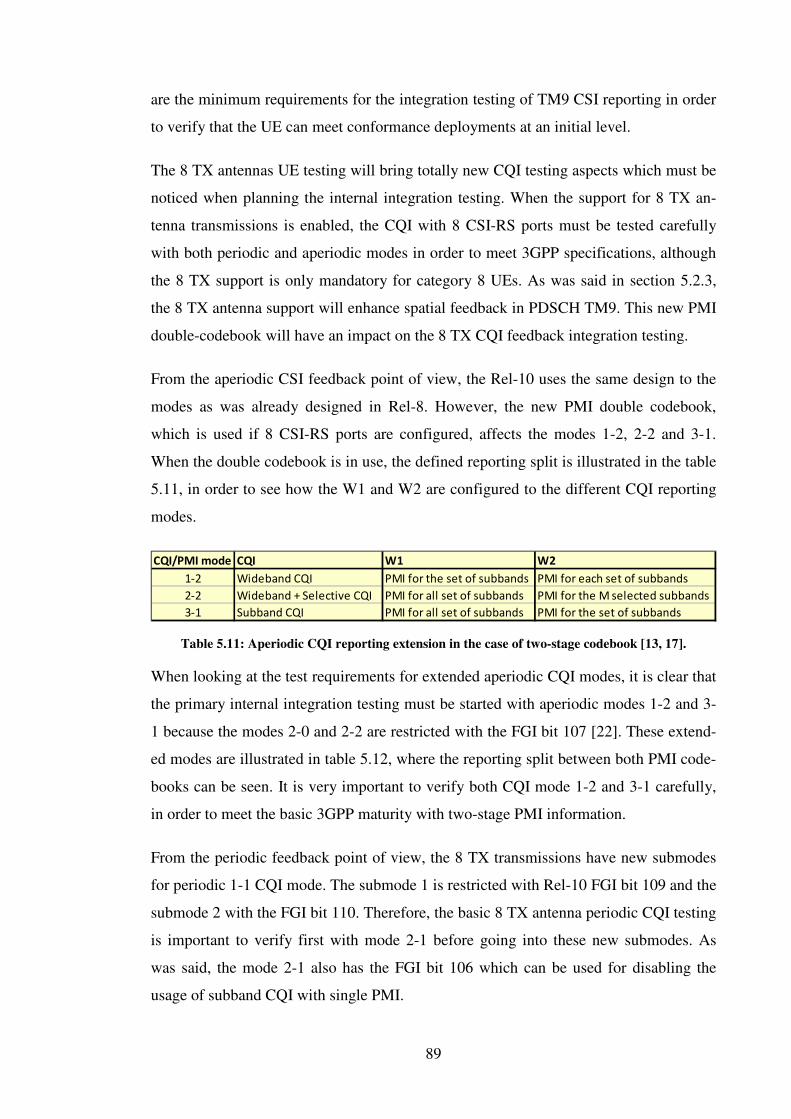
89
are the minimum requirements for the integration testing of TM9 CSI reporting in order
to verify that the UE can meet conformance deployments at an initial level.
The 8 TX antennas UE testing will bring totally new CQI testing aspects which must be
noticed when planning the internal integration testing. When the support for 8 TX an-
tenna transmissions is enabled, the CQI with 8 CSI-RS ports must be tested carefully
with both periodic and aperiodic modes in order to meet 3GPP specifications, although
the 8 TX support is only mandatory for category 8 UEs. As was said in section 5.2.3,
the 8 TX antenna support will enhance spatial feedback in PDSCH TM9. This new PMI
double-codebook will have an impact on the 8 TX CQI feedback integration testing.
From the aperiodic CSI feedback point of view, the Rel-10 uses the same design to the
modes as was already designed in Rel-8. However, the new PMI double codebook,
which is used if 8 CSI-RS ports are configured, affects the modes 1-2, 2-2 and 3-1.
When the double codebook is in use, the defined reporting split is illustrated in the table
5.11, in order to see how the W1 and W2 are configured to the different CQI reporting
modes.
Table 5.11: Aperiodic CQI reporting extension in the case of two-stage codebook [13, 17].
When looking at the test requirements for extended aperiodic CQI modes, it is clear that
the primary internal integration testing must be started with aperiodic modes 1-2 and 3-
1 because the modes 2-0 and 2-2 are restricted with the FGI bit 107 [22]. These extend-
ed modes are illustrated in table 5.12, where the reporting split between both PMI code-
books can be seen. It is very important to verify both CQI mode 1-2 and 3-1 carefully,
in order to meet the basic 3GPP maturity with two-stage PMI information.
From the periodic feedback point of view, the 8 TX transmissions have new submodes
for periodic 1-1 CQI mode. The submode 1 is restricted with Rel-10 FGI bit 109 and the
submode 2 with the FGI bit 110. Therefore, the basic 8 TX antenna periodic CQI testing
is important to verify first with mode 2-1 before going into these new submodes. As
was said, the mode 2-1 also has the FGI bit 106 which can be used for disabling the
usage of subband CQI with single PMI.
CQI/PMI mode CQI W1 W2
1-2 Wideband CQI PMI for the set of subbands PMI for each set of subbands
2-2 Wideband + Selective CQI PMI for all set of subbands PMI for the M selected subbands
3-1 Subband CQI PMI for all set of subbands PMI for the set of subbands

90
When considering the periodic wideband CQI feedback in mode 1-1, the RI/PMI/CQI
information is carried in two separate feedback reports. The first report contains the RI
information and the second one contains associated PMI/CQI information. In order to
add the two-stage codebook into the transmission, two submodes have been introduced
to the Rel-10. With higher layer signaling, the network can assign a submode to the UE
by using PUCCH_format1-1_CSI_reporting_mode parameter [22]. In submode 1, the
long-term PMI is included into the first feedback report together with the RI. In the
submode 2 on the other hand, both the long-term PMI and the short-term PMI are con-
tained in the second feedback report [17]. However, it is difficult to achieve this, and
therefore the PMI codebook in second report has to be subsampled. Both submodes
must be tested properly in order to meet the requirements for Rel-10 wideband periodic
feedbacks and the internal integration testing must also be focused on the submode 2
subsampling in order to see that the UE selects the right entries for the feedback report-
ing.
The periodic subband CQI feedback in the mode 2-1 is improved. The feedback reports
are in this case carried in three separate reports, in order to include the two-stage PMI
information into the subbands [17]. The Precoder type indicator (PTI) has been taken
into use by adding it to the RI reports so that the UE can indicate the contents of the
second and third reports [16]. By this way, the UE can estimate the variations on long-
term PMI feedback effectively. If the PTI bit is set to 0, the second report includes the
long-term PMI component for the subband and after that the third report includes the
wideband short-term PMI component jointly with the associated CQI. However, if the
long-term PMI has not modified during the reporting, the PTI is set to 1. The second
report includes wideband short-term PMI feedback jointly with associated CQI and the
third reports with short-term PMI feedback to every subband with subband CQIs [4].
This configuration is illustrated in figure 5.12, where it can be seen that the testing must
concentrate especially on the different variations between the PTI and subband PMIs in
order to verify the physical layer R&D implementation in both internal integration and
system level testing.
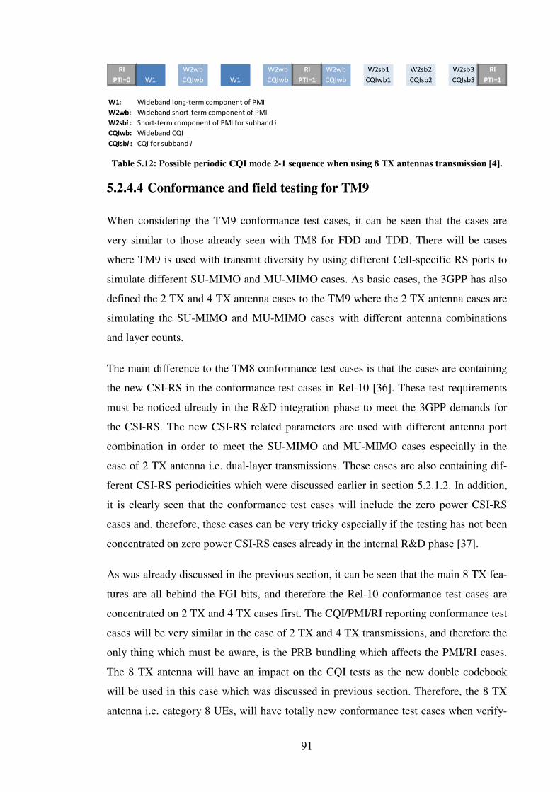
91
Table 5.12: Possible periodic CQI mode 2-1 sequence when using 8 TX antennas transmission [4].
5.2.4.4 Conformance and field testing for TM9
When considering the TM9 conformance test cases, it can be seen that the cases are
very similar to those already seen with TM8 for FDD and TDD. There will be cases
where TM9 is used with transmit diversity by using different Cell-specific RS ports to
simulate different SU-MIMO and MU-MIMO cases. As basic cases, the 3GPP has also
defined the 2 TX and 4 TX antenna cases to the TM9 where the 2 TX antenna cases are
simulating the SU-MIMO and MU-MIMO cases with different antenna combinations
and layer counts.
The main difference to the TM8 conformance test cases is that the cases are containing
the new CSI-RS in the conformance test cases in Rel-10 [36]. These test requirements
must be noticed already in the R&D integration phase to meet the 3GPP demands for
the CSI-RS. The new CSI-RS related parameters are used with different antenna port
combination in order to meet the SU-MIMO and MU-MIMO cases especially in the
case of 2 TX antenna i.e. dual-layer transmissions. These cases are also containing dif-
ferent CSI-RS periodicities which were discussed earlier in section 5.2.1.2. In addition,
it is clearly seen that the conformance test cases will include the zero power CSI-RS
cases and, therefore, these cases can be very tricky especially if the testing has not been
concentrated on zero power CSI-RS cases already in the internal R&D phase [37].
As was already discussed in the previous section, it can be seen that the main 8 TX fea-
tures are all behind the FGI bits, and therefore the Rel-10 conformance test cases are
concentrated on 2 TX and 4 TX cases first. The CQI/PMI/RI reporting conformance test
cases will be very similar in the case of 2 TX and 4 TX transmissions, and therefore the
only thing which must be aware, is the PRB bundling which affects the PMI/RI cases.
The 8 TX antenna will have an impact on the CQI tests as the new double codebook
will be used in this case which was discussed in previous section. Therefore, the 8 TX
antenna i.e. category 8 UEs, will have totally new conformance test cases when verify-
RI
PTI=0 W1
W2wb
CQIwb W1
W2wb
CQIwb
RI
PTI=1
W2wb
CQIwb
W2sb1
CQIwb1
W2sb2
CQIsb2
W2sb3
CQIsb3
RI
PTI=1
W1: Wideband long-term component of PMI
W2wb: Wideband short-term component of PMI
W2sbi : Short-term component of PMI for subband i
CQIwb: Wideband CQI
CQIsbi : CQI for subband i

92
ing the CQI/PMI/RI reporting. This must be considered already in the R&D phase in
order to meet the new category 8 UEs conformance test cases already then.
When considering the TM9 field testing as a part of system level testing, the main test-
ing from the physical layer point of view is the transmission throughputs similarly as
was discussed in the field testing of TM8 in section 4.1.3. The same interference scenar-
ios also apply in the TM9 testing and therefore the testing must take into account the
same scenarios which were already introduced in TM8 field test section in section 4.1.3.
However, as the TM9 supports the 8 TX antenna transmission, it will bring totally new
challenges to the UE field testing [4]. The main issue with higher order MIMO is the
physical space required for the antennas. It is very difficult due to constraints of the
small physical size of the UE to achieve the necessary spatial separation of antennas in
order to achieve the spatial beamforming in the channel. Also the user´s hand may inter-
fere some of the antennas, and therefore the testing in the case of 8 TX antenna must be
concentrated on some special cases that the user may cause.
5.3 Uplink MIMO transmission
In the Rel-10, the uplink transmission is extended to support up to 4x4 spatial multi-
plexing to increase the data rate for the PUSCH [6]. Also the PUCCH transmission is
enhanced by using transmit diversity in order to increase the reliability of the control
signaling. Both SU-MIMO and MU-MIMO are supported to uplink direction similarly
way as was already discussed in downlink enhancements. In addition the structure of
the uplink multi antenna precoding is very similar to that already seen in downlink an-
tenna precoding. Wideband closed-loop precoding is defined for PUSCH in both TDD
and FDD modes supporting up to four layer transmission in uplink SU-MIMO. The UE
precoder is signaled to the terminal by the eNB.
5.3.1 Enhanced Sounding reference signal
In order to support multi antenna operations, the sounding reference signal need to be
tailored. The SRS transmitted from different antennas are separated using the same
method already defined in Rel-8. By using the different cyclic shifts and transmission
combinations the transmission antennas can be separated effectively even when the UE
uses up to four uplink antenna ports [14]. However, the cyclic shifts do not guarantee

93
sufficient orthogonality between the layers in the case of uplink MIMO SRS transmis-
sions in Rel-10. Therefore, the 3GPP has defined the Orthogonal Cover Codes (OCC)
to provide an additional dimension for separating the reference signals in a reliable
manner [14].
Another SRS enhancement in Rel-10 is the introduction of dynamic aperiodic SRS. In
dynamic aperiodic SRS the eNB can request the UE to send SRS at any time by indicat-
ing it in the PDCCH [4]. This helps especially to optimize the SRS resource usage, and
prioritize the SRS capacity. Dynamic aperiodic SRS is useful particular with uplink
MIMO because periodic SRS from UEs with multiple antennas would increase the SRS
resource consumption heavily.
Aperiodic SRS is very similar to the aperiodic CQI; it is triggered by signaling on
PDCCH as a part of DCI format 0/1A/2B/2C or 4, depending on whether the transmis-
sion type is either FDD or TDD [16]. The structure of an aperiodic SRS transmission is
similar to that already used in periodic SRS. Also the aperiodic SRS is transmitted with-
in the last symbol of a subframe. Like periodic SRS, the aperiodic SRS is time instant.
The transmission time of the aperiodic SRS is always configured per UE by higher-
layer signaling.
The higher-layer aperiodic SRS configuration follows the same principle aspects which
are also used for periodic SRS configurations. The 3GPP has defined the SRS-
ConfigAp-r10 parameter for configuring the shifts and transmission combinations for
the aperiodic SRS by using the parameters cyclicShiftAp-r10 and transmissionCombAp-
r10.
As was clarified, the aperiodic SRS is configured with higher-layer signaling in order to
avoid the collisions between other SRS transmissions which are send by other UEs.
However, the aperiodic SRS is never transmitted until the UE is explicitly triggered to
do so by an explicit SRS trigger on DCI formats 0/1A/2B/2C or 4 [16]. When the UE
receives the trigger with DCI, a single SRS is transmitted in the next available aperiodic
SRS instant which was configured with parameter set by higher-layer signaling before
the trigger. The trigger is configured with an UE dedicated parameter which is called
SoundingRS-UL-ConfigDedicatedAperiodic-r10 where the different DCI formats have
their own parameters for explicitly indicating the trigger DCI format which the UE
needs to follow then.

94
5.3.2 Uplink MIMO transmission modes and DCI format 4
The concept of transmission modes has been released to SU-MIMO PUSCH transmis-
sion in Rel-10 in order to increase peak data rates on the uplink side [4]. Two PUSCH
transmission modes have been defined in Rel-10. The TM1 is very similar to that al-
ready introduced in Rel-8 and transmits from a single antenna port. The second trans-
mission mode is able to transmit from multiple antenna ports and is called TM2. In this
transmission mode the UE can be configured to transmit from either 2 or 4 antenna
ports in Rel-10.
For the TM2, the 3GPP has defined a new DCI format, called DCI format 4 [16]. When
the UE is configured to use TM2 with DCI format 4, it can transmit up to two transport
blocks per subframe with PUSCH. In the DCI format 4, each transport block is inde-
pendently acknowledged using the HARQ indicator. Also the transport block to layer
mapping uses the same rules that were already defined in Rel-8 and those are illustrated
in figure 2.8 in section 2.7.2.1. In order to indicate whether a retransmission is expected,
the DCI format 4 includes two independent NDI bits. The cyclic shift is in addition de-
fined in DCI format 4 for avoiding the collisions between UE transmissions.
Closed-loop codebook based precoding is used for the PUSCH in a very similar way to
that in PDSCH TM4 [14]. The UE is informed by the eNB about which rank and
precoder matrix should be used, as can be seen from figure 5.11. When the eNB is in
charge of both scheduling and channel estimation, there is no need for CQI/PMI feed-
back signaling. Instead, the network configures the UE to send SRS, based on which the
network can obtain uplink CSI. According to the SRS, the network can decide which
precoder and MCS should be used for transmission and indicates this to the UE. The
DM-RS from UE to network is also shown in figure 5.11. to illustrate the fact that the
SRS is used for estimating the CSI and DM-RS is used for demodulation.

95
Figure 5.11: Uplink MIMO procedure in transmission mode 2 [14].
The used codebook design for uplink is very different from that used for downlink. This
is because the power consumption is limited in the UE and thus the codebook needs to
take the usage of power amplifiers into account. Another uplink specific property of the
uplink codebooks are the antenna selection elements. These elements can be used to
turn off and on the terminal antennas to save the UE battery power.
5.3.3 Uplink MIMO testing aspects
From the Rel-10 testing point of view the uplink MIMO is a very tricky feature to be
tested. As the CA and TM9 are the main features of Rel-10 from the physical layer
point of view, the operators probably will not have much interest to the uplink MIMO.
The initial uplink MIMO UE deployments will only have one or two antennas in the
uplink direction. This must be noticed when planning the internal integration testing as
the interests might change at some point dramatically, for example if the cloud compu-
ting makes its breakthrough and the need for higher uplink throughputs increases ac-
cordingly for UEs.
When considering the initial SRS deployments, it can be seen that the new OCC separa-
tion between reference signals is restricted with the FGI bit 101 [22]. As the OCC sepa-
ration between the layers is needed in order to support at least two layer deployments in
the uplink MIMO, it can be seen that the first uplink MIMO deployments are only using
the transmit diversity with one layer on PUSCH. In addition, the aperiodic SRS is also
restricted with the FGI bit 102. Therefore, the internal integration testing must first be
concentrated on periodic SRS in order to meet the initial Rel-10 requirements in the
case of uplink MIMO.

96
As was said in the section 5.1.2.3, the 3GPP has defined the two-
AntennaPortsForPUCCH-r10 parameter for restricting the transmit diversity support
for PUCCH. This leads to a situation where UE can block out all the new Rel-10 fea-
tures from the uplink. From the physical layer testing point of view, the initial testing of
uplink MIMO will only include a so called release update as the Rel-8/9 baseline must
be transferred to Rel-10 TM1 deployment with DCI format 0 and consequently the test-
ing does not contain any actual new features.
The 3GPP has started the discussion about the uplink MIMO conformance test cases, it
has been stated that the maximum supported layer count will be two in the Rel-10
timeframe as the maximum antenna connector count is as well two [38]. Therefore, the
conformance test cases will also contain some TM2 cases and this must be taken into
account when planning the internal R&D integration and system level testing to meet
the 3GPP demands. As the discussion is still at an early stage it might change in the
future as the operators do not have any interests in the uplink MIMO at the moment.
Before going into the possible uplink MIMO conformance test cases it is good to take a
look at some issues which the layer two deployments will have to the other Rel-10 fea-
tures and how it will affect to the physical layer testing.
When the two layer TM2 uplink MIMO is needed for the 3GPP conformance test cases,
the testing must first be concentrate on the OCC separation which must be enabled for
the two layer transmissions. As the PUSCH TM2 is very similar to the closed-loop
PDSCH TM4, the testing aspects of the uplink DCI format 4 can be reused here in the
R&D phase.
The internal integration testing must include the basic throughput cases where the UE
uses different antenna combinations in the case of rank 1 by simulating the SU-MIMO
and MU-MIMO cases with different MCS values on different bandwidths. In the case of
rank 2, the testing must concentrate on the cases where uplink control signaling is
transmitted on PUSCH as this will cause interesting situations. In these cases it must be
verified that the ACK/NACK and RI values are replicated across all the layers because
the control data is channel coded and multiplexed with the data. If this is not verified
properly, it might lead to CRC fails on the network side.
In the case of CQI and PMI reporting, the reports are mapped only to the codeword with
the highest MCS as is indicated by the initial uplink grant. However, in the case where

97
both codewords have the same MCS value, the codeword 0 is always selected for the
CQI and PMI reporting. In addition, the two layer transmission also effect on the UCI
transmission and this must be noticed when planning the test requirements for the two
layer uplink MIMO.
As was already pointed out, the uplink MIMO conformance test cases are still under
discussion and, therefore, it is hard to know for sure what kind of cases the 3GPP RAN5
will decide on. However, it is most likely that the 3GPP will have the basic transmission
cases for uplink TM1, and this must be verified already in the R&D integration phase.
The TM2 will have much more complicated cases but with a sufficient test plan, as was
discussed in this thesis, the test cases will include the basic high data rate cases and the
control signaling cases.
From the uplink MIMO field testing point of view, testing should be concentrated on
cases similar to those already discussed for TM8 and TM9. The different interference
scenarios together bring very interesting test conditions for the uplink MIMO where the
testing must concentrate especially on the data throughputs from the physical layer
point of view.
Another very important testing aspect is the power consumption. As the 3GPP has lim-
ited the UE´s maximum transmit power to 23 dBm, the power must be shared across the
amplifiers/antennas [13]. This will affect some receiver functions such as channel esti-
mation and frequency tracking. The channel conditions may vary very much in the real
life conditions, these kinds of problems must be tested properly. As the physical size of
the UE is typically small, the antenna placement may cause problems as was discussed
also in TM9 field testing section 5.2.4.4. The power imbalance may differ between the
antennas due to UE orientation or how the UE is held by the user. These kinds of situa-
tions must be tested carefully in order to provide quality thus a good user experience.

98
6 CONCLUSIONS
The main target of this thesis was to analyze the Rel-9 and Rel-10 features from the
physical layer point of view and to evaluate the testing requirements for these features.
The purpose was to introduce the new features and to study the internal integration and
system level testing aspects deeply and also to inspect the conformance test cases for a
specific feature with different field testing aspects.
The analysis showed that the Rel-9 contains only two new major features which have a
great effect on the physical layer testing. These features are the dual-layer beamforming
called TM8 and the positioning methods named OTDOA and E-CID.
The TM8 testing requirements mainly affect the TDD testing as the TM8 is not manda-
tory for UEs which only support FDD. The internal integration and system level testing
contain testing requirements especially for the new DCI format 2B and CQI reporting. It
was also noticed that the MU-MIMO aspects must be considered when planning the
testing activities for the TM8.
Furthermore, LTE positioning methods OTDOA and E-CID have testing requirements
from the physical layer point of view. It was shown that the OTDOA is based on PRSs
and therefore the testing requires that the timing and muting of PRS must be verified. In
addition, OTDOA has totally new conformance test cases which must be considered
already in integration testing phase to achieve accurate UE positioning. Also E-CID has
similar testing aspects to the UE positioning accuracy and to the estimation of receive-
transmit duration.
The Rel-10 analysis of the physical layer aspects showed that the transition from LTE to
LTE-Advanced brings many new testing requirements which must be considered when
planning the Rel-10 testing activities in order to see that the UE meets the next genera-
tion mobile access network demands.
Analysis showed that the largest testing requirements originate from the CA which is
the most important Rel-10 feature and also has a great impact on the physical layer de-
sign and testing. Different CA deployment aspects were analyzed and it was seen that
the initial CA test requirements consist of two downlink CCs and one uplink CC in the
case of FDD. In TDD deployments, there are two downlink CCs and two uplink CCs.

99
The asynchronous deployments in CA on FDD require novel test requirements which
must be taken into account carefully for UE feedback reporting like HARQ feedback
and CSI feedback testing. The analysis showed especially that the feedback reporting
has some very complex scenarios where different prioritizations must be utilized in or-
der to avoid collisions between different report types.
The second Rel-10 feature that was analyzed was the multi-layer beamforming i.e.
TM9. As mentioned, this feature has a great effect on the physical layer testing where
the requirements must especially be concentrated on the new DCI format 2C and on the
CSI-RS. The main testing requirements come from the multi-layer transmissions which
utilize different SU-MIMO and MU-MIMO deployments on the UE. The analysis also
showed that the 3GPP has defined many FGIs to restrict some deployment scenarios
and these restrictions must be taken into account in testing in order to at first focus on
the mandatory aspects of TM9. In addition, it was shown that the MU-MIMO has its
first opportunity for the true commercial breakthrough, and therefore these aspects must
also be considered when planning the testing activities.
The last main feature that was analyzed in this thesis was the uplink MIMO which
brings testing requirements where two transport blocks are used on uplink to utilize
even higher uplink throughputs. From the physical layer point of view, this feature
brings testing activities for the new DCI format 4 and different control signaling as-
pects. It was however seen that the uplink MIMO aspects are not as important as the CA
and TM9 as the 3GPP has restricted the uplink to use only transmit diversity by using
the FGI bits. Therefore, uplink MIMO does not have such a great impact on the test
requirements at this point in time.

100
REFERENCES
[1] 3GPP TR 25.913, “Requirements for Evolved UTRA (E-UTRA) and
Evolved UTRAN (E-UTRAN)”, Release 9, December 2009.
[2] 3GPP TS 36.300, “Evolved Universal Terrestrial Radio Access (E-UTRA)
and Evolved Universal Terrestrial Radio Access Network (E-UTRAN):
Overall description”, Stage 2, Release 10, June 2012.
[3] Agilent Technologies.: LTE and the Evolution to 4G Wireless: Design and
Measurement Challenges. Agilent Technologies, China, 2009.
[4] Baker M., Sesia S., Toufik I.: LTE – The UMTS Long Term Evolution:
From Theory to Practice, John Wiley & Sons Ltd, United Kingdom, 2011.
[5] Beming P., Dahlman E., Parkvall S., Sköld J.: 3G Evolution: HSPA and
LTE for Mobile Broadband. Elsevier, United Kingdom, 2008.
[6] Dahlman E., Parkvall S., Sköld J.: 4G LTE/LTE-Advanced for Mobile
Broadband. Elsevier, United Kingdom, 2011.
[7] Holma H., Toskala A.: LTE for UMTS: OFDMA and SC-FDMA Based
Radio Access. John Wiley & Sons Ltd, United Kingdom, 2009.
[8] Khan F.: LTE for 4G Mobile Broadband: Air Interface Technologies and
Performance. Cambridge University Press, United Kingdom, 2009.
[9] 3GPP, “Overview of 3GPP Release 9”, June 2011.
[10] 3GPP, “Overview of 3GPP Release 10”, June 2011.
[11] 3GPP, “Overview of 3GPP Release 11”, June 2011.
[12] 3GPP TR 25.892, “Feasibility Study for Orthogonal Frequency Division
Multiplexing (OFDM) for UTRAN enhancement”, Release 6, June 2004.
[13] Ghosh A., Ratasuk R.: Essentials of LTE and LTE-A. Cambridge Univer-
sity Press, United Kingdom, 2011

101
[14] Holma H., Toskala A.: LTE for UMTS: Evolution to LTE-Advanced. John
Wiley & Sons Ltd, United Kingdom, 2011.
[15] 3GPP TS 36.211, “Physical Channels and Modulation”, Release 10, June
2012.
[16] 3GPP TS 36.212, “Multiplexing and channel coding”, Release 10, June
2012.
[17] 3GPP TS 36.213, “Physical layer procedures”, Release 10, June 2012.
[18] 3GPP TS 36.913, “Requirements for further advancements for Evolved
Universal Terrestrial Radio Access (E-UTRA) (LTE-Advanced)”, Release
10, March 2011.
[19] 3GPP TS 36.912, “Feasibility study for Further Advancements for E-
UTRA (LTE-Advanced)”, Release 10, March 2011.
[20] 3GPP TS 36.101, “User Equipment (UE) radio transmission and recep-
tion”, Release 10, July 2012.
[21] 3GPP TS 36.521-1, “User Equipment (UE) conformance specification
Radio transmission and reception Part 1: Conformance Testing”, Release
10, July 2012.
[22] 3GPP TS 36.331, “Radio Resource Control (RRC); Protocol specifica-
tion”, Release 10, July 2012.
[23] Jiaheng W., Payaro M.: On the Robustness of Transmit Beamforming.
Signal Processing, IEEE Transactions on, 2010, 58(11), p.5933-5938.
[24] Irmer, R. et al.: Multisite field trial for LTE and advanced concepts.
Communications Magazine, IEEE, 2009, 47(2), p.92-98.
[25] 3GPP TS 36.302, “Services provided by the physical layer”, Release 10,
March 2012.
[26] 3GPP TS 36.321, “Medium Access Control (MAC) protocol specifica-
tion”, Release 10, March 2012.

102
[27] Furuskog, J., Kangas, A., Medbo, J., Siomina, I.: Propagation channel
impact on LTE positioning accuracy: A study based on real measurements
of observed time difference of arrival. Personal, Indoor and Mobile Radio
Communication, IEEE 20th International Symposium on, 2009, p.2213-
2217.
[28] Buehrer R. M., Zekavat R.: Handbook of Position Location: Theory, Prac-
tice and Advances. Wiley-IEEE Press, New Jersey, 2011.
[29] 3GPP Contribution R1-092307, “Analysis of UE Subframe Timing Offset
Measurement Sensitivity to OTDOA Performance”, TSG-RAN WG1,
June 2009.
[30] 3GPP Contribution R1-091979, “Further performance evaluation of UE
Positioning Based on AoA+TA”, TSG-RAN WG1, May 2009.
[31] 3GPP TS 37.571-1, “User Equipment (UE) conformance specification for
UE positioning; Part 1: Conformance test specification”, Release 10, July
2012.
[32] 3GPP TS 37.571-5, “User Equipment (UE) conformance specification for
UE positioning; Part 5: Test scenarios and assistance data”, Release 10,
July 2012.
[33] 3GPP TS 36.355, “LTE Positioning Protocol (LPP)”, Release 10, July
2012.
[34] 3GPP Contribution R1-091595, “Performance of UE Positioning Based on
AoA+TA”, TSG-RAN WG1, March 2009.
[35] 3GPP TS 36.306, “User Equipment (UE) radio access capabilities”, Re-
lease 10, June 2012.
[36] 3GPP Contribution R4-116270, “CQI reporting accuracy test on fre-
quency-selective scheduling on eDL MIMO”, TSG-RAN WG4, Novem-
ber 2011.
103
[37] 3GPP Contribution R4-120953, “Introduction of TM9 demodulation per-
formance requirements”, TSG-RAN WG4, February 2012.
[38] 3GPP Contribution R1-105036, “WF on UE Category for Rel. 10”, TSG-
RAN WG1, August 2010.
[39] Rohde&Schwarz homepage (accessed 2012) URL: http://www2.rohde-
schwarz.com/en/products/test_and_measurement/mobile_radio/
[40] 3GPP TS 36.521-3, “User Equipment (UE) conformance specification;
Radio transmission and reception; Part 3: Radio Resource Management
(RRM) conformance testing”, Release 10, June 2012.
[41] 3GPP Contribution R5-112447, “Carrier Aggregation and Release 10 re-
lated work”, TSG-RAN WG5, May 2011.
[42] Guangxiang Y., Xiang Z., Wenbo W., Yang Y.: Carrier aggregation for
LTE-advanced mobile communication systems. Communications Maga-
zine, IEEE, 2010, 48(2), p.88-93.
[43] Qingzhan Z., Zhiping S., Wentao W., Zijia H.: Analyses of Interferences
between Component Carriers in Carrier Aggregation. Communications
and Mobile Computing (CMC), IEEE, 2011, p.420-423.
[44] 3GPP Contribution R4-114849, “List of RRM Test Cases for Carrier Ag-
gregation”, TSG-RAN WG4, August 2011.
[45] Nakamura T.: LTE Rel-9 and LTE-Advanced in 3GPP. NTT Docomo,
2009, press release.
[46] Anuradha B., Parikh J.: LTE Advanced: The 4G Mobile Broadband Tech-
nology. International Journal of Computer Applications (0975 – 8887),
January 2011, 13(5), p.17-21.
[47] 3GPP: Active work item program (accessed 2012) URL:
http://www.3gpp.org/ftp/Specs/html-info/GanttChart-Level-2.htm
[48] Fox D.: Testing UMTS: Assuring Conformance and Quality of UMTS Us-
er Equipment. John Wiley & Sons Ltd, United Kingdom, 2008.