Embed Size (px)
Citation preview

3D-Model Based Enterprise a SASIG initiative
Ram Pentakota
Director, Global Engineering Application Services Johnson Controls Automotive Seating

SASIG is a global consortium of automotive standards organizations.
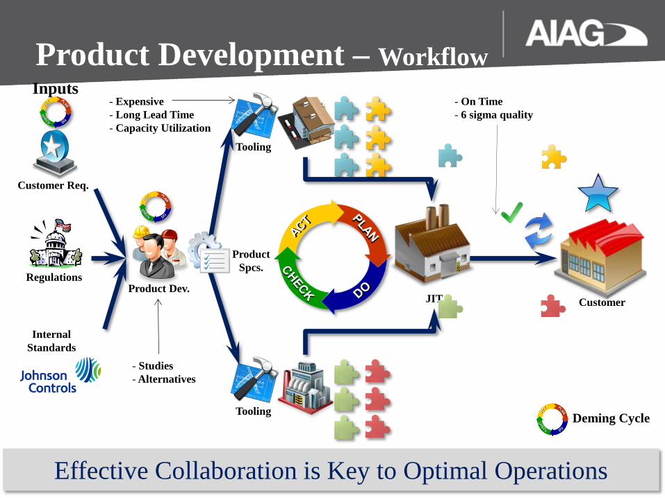
Internal Standards
Regulations
Customer Req.
Tooling
Tooling
Customer JIT Product Dev.
- Expensive - Long Lead Time - Capacity Utilization
- On Time - 6 sigma quality
Product Development – Workflow
Product Spcs.
Effective Collaboration is Key to Optimal Operations
Deming Cycle
- Studies - Alternatives
Inputs

What is ?
3D GD&T (Model Based Definition) is a system in which product details are captured directly in the 3D model.
5 Embedded GD&T
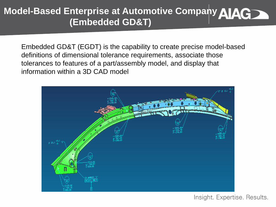
Embedded GD&T (EGDT) is the capability to create precise model-based definitions of dimensional tolerance requirements, associate those tolerances to features of a part/assembly model, and display that information within a 3D CAD model
Model-Based Enterprise at Automotive Company (Embedded GD&T)

Why ?
Where is my Datum A ?
(Difficult to Communicate GD&T Content)
The highlighted area is Datum A
(Easy to Communicate GD&T Content)
Drawings 3D GD&T

Why ?
How many Datums do I have ? (Difficult to manage GD&T Content)
I have Datums A,B,C,D,F
(Easy to manage GD&T Content)
Drawings 3D GD&T

Why ?
Do I have any GD&T Mistakes?
(No Quality GD&T Check)
I have a Problem With Datum A
(Automatic GD&T Quality Checks)
Drawings 3D GD&T Datum A Errors

– Intelligent Content w/Quality Checks Why
Intelligent system 1- GD&T quality 2- engineer’s GD&T skills

– Checking Inter-level zone dependencies Part
Drawing Assembly Drawing
Why
Component details not visible at the assembly level
Product Details Managed on Separate Drawings
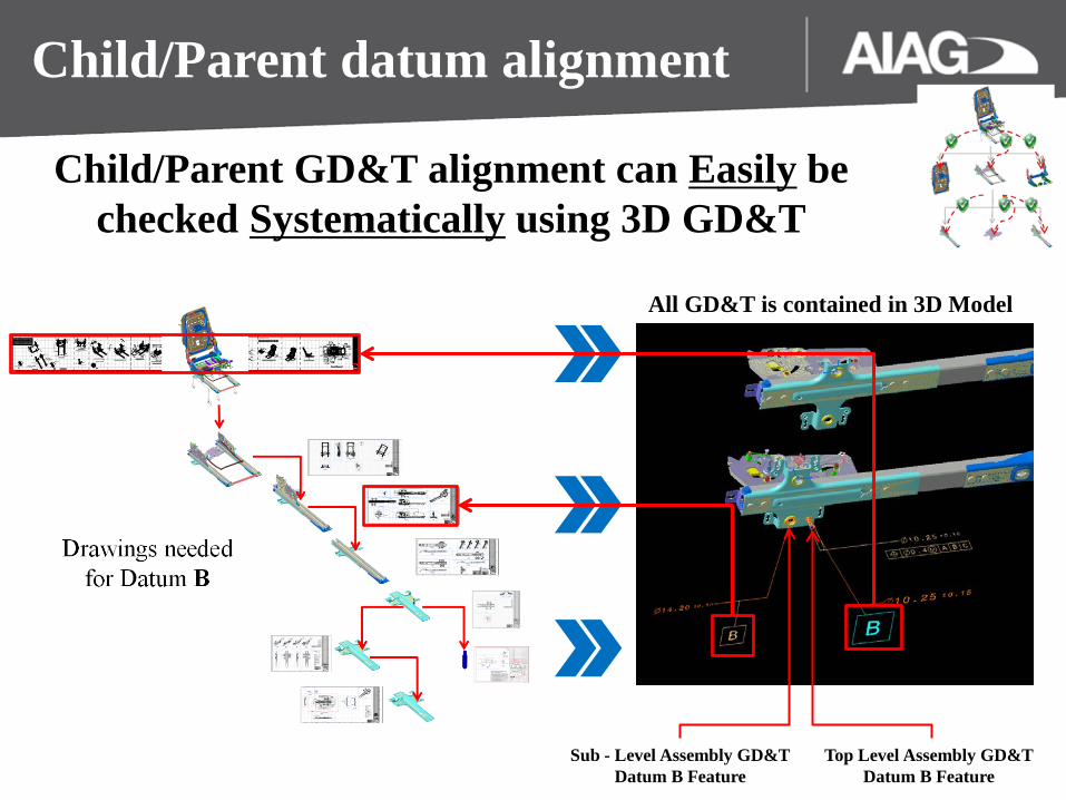
Child/Parent datum alignment
Top Level Assembly GD&T Datum B Feature
Child/Parent GD&T alignment can Easily be checked Systematically using 3D GD&T
Sub - Level Assembly GD&T Datum B Feature
All GD&T is contained in 3D Model

Manufacturing Design
Build Fixture
Check Fixture
A
B
C
Controlled Part Features
GD&T CAD
A
B
C MBD Model
Why do we need 3D MBE? Drawings Limitations/Issues 3D Product Definition Model Benefits 2D Skills in a 3D World
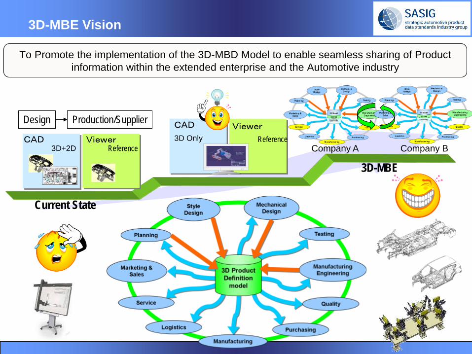
Company A Company B
Design Production/Supplier
3D+2DCAD Viewer
Reference
CAD Viewer
3D Only Reference
3D-MBE Vision
To Promote the implementation of the 3D-MBD Model to enable seamless sharing of Product information within the extended enterprise and the Automotive industry
3D-MBE
Current State
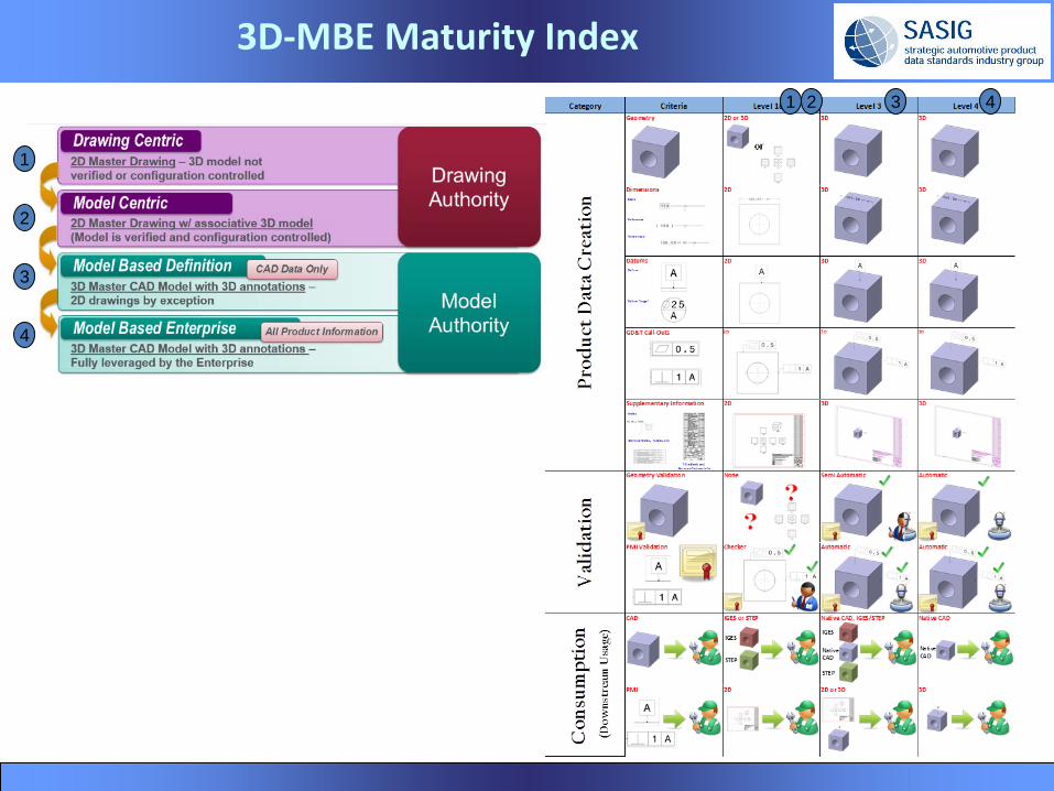
3D-MBE Maturity Index
3
2
1
4
1 2 3 4

3D-MBE Benefits Category Key Enablers Typical Range
Designer Efficiency •GS&T advisor supported GD&T information added to 3D model
10 - 30%
Engineering Efficiency •Reduced involvement in repeat drawing creation iterations for GD&T information checking and validation
5 – 10%
Engineering effectiveness improvement
•Productivity gains to effectiveness 10 – 20%
Reduced need for manufactured part checking
•Access to correct GD&T information for manufacturing process planning
15 - 25%
Reduced Rework and Scrap •Access to correct product information 10 – 20%
Reduced Cost of Quality •Access to correct GD&T information for manufacturing process planning
2 – 10 %
Improved win rate (and margins) through higher quote confidence
•Sufficient time for cost estimation and sourcing based on timely and accurate PMI data availability
TBD
Quality of Life Improvement •Eliminate non-value work Intangible but Significant
Risk mitigation against significant product fulfillment error
•Single source of product information •Access to correct product information to all stakeholders
Significant
Target: Reduction in physical parts and testing by 50%
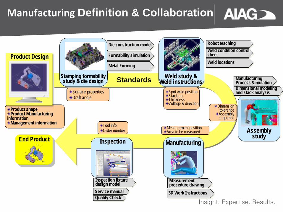
Manufacturing Definition & Collaboration
Stamping formability study & die design
Inspection Assembly
study
Manufacturing Process Simulation
Inspection fixture design model
Measurement procedure drawing
Service manual
Dimensional modeling and stack analysis
Product shape Product Manufacturing
information Management information
Product Design
Surface properties Draft angle
Spot weld position Stack up Thickness Voltage & direction Dimension
tolerance Assembly sequence
Measurement position Area to be measured
Manufacturing
Tool info Order number
Die construction model
Formability simulation
Metal Forming
Robot teaching Weld condition control sheet Weld locations
3D Work Instructions Quality Check
End Product
Weld study & Weld instructions Standards

What is role of Drawing?
Current State
CAD 3D Model
2D Paper
Certification Marketing
Service
Logistics
Parts list
Die & Eqt
Analysis Design
Supplier
Interference Cost
Verification Tests
Inspect model
Meetings
Inspection
Assembly
Machining
Place order
Supplier
Viewer Bidding
Process
Packaging Arrange order
Future State
CAD 3D Model Certification Marketing
Service
Logistics
Parts list
Die & Eqt
Analysis Design
Supplier
Interference
Cost
Verification Tests
Inspect model
Meetings
Inspection
Assembly
Machining
Place order
Viewer
Bidding Process
Packaging Arrange order
Supplier
Too big of a jump
All major OEMs have been trying for the past 10 years to implement full 3D.

What to do about operations that was always done in 2D?
3D-MBE Interim Approach
2D Only 3D+2D(2D+3D)
3D Only 3D + Automatic 2D
Continue 2D operations in the transitioning stage
Start transition to 3D models
Address issues in the transitioning stage
・Addressing 2D drawing for legal compliance Document for submission to government agencies Contracts with suppliers
・Addressing the existing 2D drawing process Drawing mark ups made at work site Circulated by physically providing on site in paper
・Being able to see the whole drawing at once Paper drawings spread out line side
・Size reduction to send files ・No tools necessary (PCs not needed) ・Management of approved information
Future
3D penetration rate
2D drawing automatically created with 3-view drawings and layout of views
To address the 2D drawing processes
Disposed
2D drawing operation

Visualization CAD
3D MBD Utilization Native CAD
Prototype Part
3D PDF JT Eng.
AQEs
Purchasing Suppliers
Eng. Suppliers
Etc,
AMEs
Tool Shop
Design
Costing

Man-hour reductions Using 3D Annotated Model
Manufacturing Work Instructions Product Development
Man-hours for creation
3D Annotated
Model
3D + 2D
▲50%
Man-hours for creation
3D Annotated
Model
3D + 2D
▲50%
An OEM study validated a 50 % man-hour reduction using 3D Annotated Models

Virtual Verification
Virtual verification (Compare a scanned part to 3D GD&T model) Higher priority for profile and position based callout in GD&T compare
Virtual verification can significantly reduce PPAP cost and be a powerful tool in 6 sigma studies
GD&T Scanned Part

Model Based Dimensional Analysis

Technical Data Package Release to Release GD&T Compare
New Annotations Old Annotations Supplier BOM Package

3D Master: Important points to be considered
Departments Barriers
Impacts on internal Processes
Communication and Collaboration
Evolution of certification
Impacts on Supply Chain
Cultural Change Think 3D and not 2D

Thank You