Embed Size (px)
Citation preview
663
Proceedings of the IMProVe 2011
International conference on Innovative Methods in Product Design
June 15th – 17th, 2011, Venice, Italy
3D CAD and multi-domain simulation integration for Energy Scavenger design
S. Tornincasa (a), E. Bonisoli (a), F. Di Monaco (a) (a) Department of Production Systems and Business Economics, Politecnico di Torino, ITALY
Article Information
Keywords: Virtual Prototyping, CAD-CAE integration, Multi-domain Simulation, Energy Harvester.
Corresponding author: Stefano Tornincasa Tel.: +39 011 090 7274 Fax.: +39 011 090 7299 e-mail: [email protected] Address: C.so Duca degli Abruzzi, 24 10129 Torino, ITALY
Abstract
This paper presents an example of integration between 3D CAD models and multi-domain simulation applied to the optimization of an energy scavenger device. A MATLAB® framework controls a block-oriented Simulink® model of the energy scavenger, drives the FEMM finite element magnetic simulation of the device and manages the updating of the SolidWorks® CAD models. All the model parameters are stored in a unique data file from which data for all simulations and models are extracted. This leads to a reduction in both the number of errors produced and the time required at the design stage. Moreover constructive drawings are automatically updated and are immediately suitable for tolerance and design constraints checks and also for the effective prototyping of the device. Constructed prototypes are suitable for experimental tests and model performance validations.
1 Introduction In the field of Virtual Prototyping [1] and Simulation
Based Design [2-3] the main objective has always been to achieve the widest possible integration between different design tools in order to optimize, simplify and speed up the design process from the initial drafts to the final validation [4-6]. This integration is usually accomplished between 3D CAD, FEM and multi-body dynamics analysis instruments, which are often already available in the majority of CAE packages [7-9]. A further Widely used technique is co-simulation between different time-domain lumped parameters simulation environments to simulate both control and controlled system and interactions between complex multi-domain systems [10-12]. Even so it is very rare to find in literature examples of interaction and automatic data exchange between this last kind of simulation environments and 3D CAD systems [13-15].
For these reasons a MATLAB® based platform has been developed to allow the integration of different designs and simulation environments thus reducing, simplifying and automating a lot of iterative editing operations. The proposed methodology, in this case applied to an Energy Scavenger device powering a tyre sensor node [16], can be transferred to a wide variety of situations.
This methodology, starting from a single configuration file containing geometric and functional system parameters, can automatically execute simulations, FEM analysis, CAD models and constructive drawings in order to validate design and build prototypes. In this way a complete and effective multi-directional integration between different software environments, concerning
different and distant engineering aspects, has been achieved.
To create this platform following software tools have been used: - MATLAB®: the well known numerical computing
environment and programming language has been used to the management and hierarchical structure operations.
- Simulink®: the MATLAB® simulative tool has been used to create a block-oriented substructured environment for the development of the physical model of the system.
- Finite Element Method Magnetic (FEMM): is a freeware powerful finite element tool for 2D and axial-symmetric electro-magnetic field computing. It has been used to calculate magnetic forces and fluxes maps.
- SolidWorks®: reference software in the field of mechanical design and drawing suitable both for preliminary models, as the methodological set-up of new design proposals, and to develop detailed models and drawings.
2 Device working principle The device under examination is a vibrational magneto-
mechanic energy scavenger conceived to power a remote sensor mounted on the inner-liner of a tyre [16]. The sketch of the device is shown in fig. 1.
When revolving around its axis, the external surface of the tyre is subjected to high deformation gradients when contacting ground. An energy scavenger, bonded to the

664
S. Tornincasa et al. 3D CAD and multi-domain simulation integration for Energy Scavenger design
June 15th – 17th, 2011, Venice, Italy Proceedings of the IMProVe 2011
inner layer of the tyre, follows the imposed external deformation.
Fig. 1 Energy scavenger sketch (the figure is not to scale)
In fig. 2 the main phases involved in the energy scavenger dynamic behaviour are sketched: 1) the tyre doesn’t touch the ground, so the scavenger
is subjected to radial (centripetal) acceleration, therefore a centrifugal force acts on the device;
2) the tyre arrives up to the ground and is deformed, so the scavenger is subjected to an acceleration peak;
3) the tyre is on the ground (contact patch, footprint) and it moves with a straight motion, the radial acceleration quickly drops to zero;
4) the tyre leaves the ground contact and the scavenger is again subjected to another acceleration peak.
Fig. 2 Energy scavenger behaviour during wheel rotation (the figure is not to scale)
The floating magnet inside the scavenger is radially repelled toward the revolution axis during the third phase and again it is forced toward the inner liner during the fourth phase. The motion of the floating magnet is responsible for the energy conversion. The main details of the scavenger are shown in fig. 1. The floating magnet has a magnetization axis parallel to the guide axis, which is fixed radially in the tyre. The inner size of the guide is slightly bigger than the magnet, in order to allow the air to flow through the two chambers above and below the magnet. Two rubber bumpers are bonded to the upper and lower lids to prevent fatal collisions of the magnet at the end of the strokes. Between the lids are wound two coils, divided by a separator connected to the guide. When the floating magnet moves along the guide, excited
by the external deformation of the tyre, the variation of the magnetic flux linked to the coils produces an electromotive force that can be used as power supply for an electrical load. The coils are series connected and wound in opposite direction so that to sum their electromotive force. A lower, smaller and fixed magnet has an elastic nonlinear preload function: when the tyre is on the ground (phase 3), it repels the floating magnet toward the wheel axis, allowing the active motion. The behaviour of the dynamic system will be adaptive resonant, due to the fact that during the undeformed tyre arc the floating magnet displacement and the resonant dynamic properties are dependent with respect to the wheel speed. An external shell of soft magnetic composite material (SMC) can be added to contain magnetic flux and flux linking with coils.
3 Design, simulation and optimization multi-software framework
A framework in which MATLAB® manages and drives all the other software tools for simulations, data exchange and CAD models updating (fig. 3), has been developed in order to allow a correct and effective interaction between the different components of the device.
Fig. 3 Interactions between software tools
Particularly through a sequence of MATLAB® functions the following operations are provided: - to define the geometrical characteristics by the
creation of a shared parametric model used by all simulative tools, multibody (MB) and finite element models (CAE) and 3D modeling software (CAD);
- to compile SolidWorks® in order to obtain an automatic model and drawings update from geometric data file;
- to pilot FEMM in order to calculate magnetic forces and linked fluxes maps for the substructured multibody model;
- to pilot Simulink® models starting from geometric data, magnetic maps and accelerometric data available for the different vehicle speeds. It is also possible to perform simulation sequences with variable parameters to make comparisons or optimizations;
- to post-process data for further elaborations and to compare different configurations or simulation and experimental results.
3.1 Functional parameterization choices
One of the key aspects in the realization of this platform is the most convenient choice of the geometrical parameters of the Energy Scavenger components. This is not an unambiguous choice but it is fundamental to take into account all the relationships linked to the industrialization and production aspects of the
665
S. Tornincasa et al. 3D CAD and multi-domain simulation integration for Energy Scavenger design
June 15th – 17th, 2011, Venice, Italy Proceedings of the IMProVe 2011
components. Through these parameters, both the geometric description of the device and its functional simulation are completely defined. The chosen parameters are used to compile a configuration file suitable both for simulation environments and solid models.
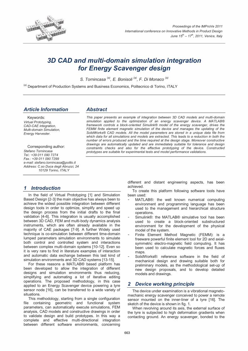
Parameters should be chosen in order to avoid redundancy, conflicts and ambiguity. It is also necessary to preserve parameters independence and at the same time minimize their number [17]. As an example (fig. 4) since the nominal inner diameter of the guide and the floating magnet one are the same, their quotes are directly obtained from the same parameter dm. Similarly the inner coils radius, as its sizes are tightly linked to the guide, is not directly parameterized but its value is calculated as the sum of dm/2 and guide thickness dr_guide and the external one as sum of the calculated inner radius and coil thickness dr_coil.
Fig. 4 Energy scavenger geometry parameterization
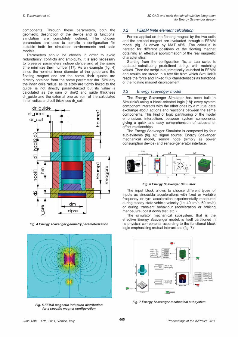
Fig. 5 FEMM magnetic induction distribution for a specific magnet configuration
3.2 FEMM finite element calculation
Forces applied on the floating magnet by the two coils and the preload magnet are evaluated through a FEMM model (fig. 5) driven by MATLAB®. The calculus is iterated for different positions of the floating magnet obtaining an effective approximation of the real magnetic characteristics.
Starting from the configuration file, a Lua script is updated substituting predefined strings with matching values. Then the script is automatically launched in FEMM and results are stored in a text file from which Simulink® reads the force and linked flux characteristics as functions of the floating magnet displacement.
3.3 Energy scavenger model
The Energy Scavenger Simulator has been built in Simulink® using a block-oriented logic [18]: every system component interacts with the other ones by a mutual data exchange about actions and reactions between the same components. This kind of logic partitioning of the model emphasizes interactions between system components giving a quick and easy comprehension of cause-and-effect relationships.
The Energy Scavenger Simulator is composed by four sub-systems (fig. 6): signal source, Energy Scavenger mechanical model, sensor node (simply as power consumption device) and sensor-generator interface.
Fig. 6 Energy Scavenger Simulator
The input block allows to choose different types of inputs as sinusoidal accelerations with fixed or variable frequency or tyre acceleration experimentally measured during steady-state vehicle velocity (i.e. 40 km/h, 60 km/h) or during transient behaviour (acceleration or braking manoeuvre, coast down test, etc.).
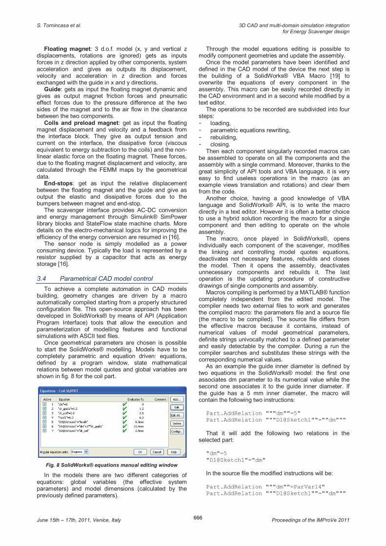
The simulator mechanical subsystem, that is the effective Energy Scavenger model, is itself partitioned in its physical components according to the functional block logic emphasizing mutual interactions (fig. 7).
Fig. 7 Energy Scavenger mechanical subsystem
666
S. Tornincasa et al. 3D CAD and multi-domain simulation integration for Energy Scavenger design
June 15th – 17th, 2011, Venice, Italy Proceedings of the IMProVe 2011
Floating magnet: 3 d.o.f. model (x, y and vertical z displacements, rotations are ignored) gets as inputs forces in z direction applied by other components, system acceleration and gives as outputs its displacement, velocity and acceleration in z direction and forces exchanged with the guide in x and y directions.
Guide: gets as input the floating magnet dynamic and gives as output magnet friction forces and pneumatic effect forces due to the pressure difference at the two sides of the magnet and to the air flow in the clearance between the two components.
Coils and preload magnet: get as input the floating magnet displacement and velocity and a feedback from the interface block. They give as output tension and current on the interface, the dissipative force (viscous equivalent to energy subtraction to the coils) and the non-linear elastic force on the floating magnet. These forces, due to the floating magnet displacement and velocity, are calculated through the FEMM maps by the geometrical data.
End-stops: get as input the relative displacement between the floating magnet and the guide and give as output the elastic and dissipative forces due to the bumpers between magnet and end-stop.
The scavenger interface provides AC-DC conversion and energy management through Simulink® SimPower library blocks and StateFlow state machine charts. More details on the electro-mechanical logics for improving the efficiency of the energy conversion are resumed in [16].
The sensor node is simply modelled as a power consuming device. Typically the load is represented by a resistor supplied by a capacitor that acts as energy storage [16].
3.4 Parametrical CAD model control
To achieve a complete automation in CAD models building, geometry changes are driven by a macro automatically compiled starting from a properly structured configuration file. This open-source approach has been developed in SolidWorks® by means of API (Application Program Interface) tools that allow the execution and parameterization of modelling features and functional simulations with ASCII text files.
Once geometrical parameters are chosen is possible to start the SolidWorks® modelling. Models have to be completely parametric and equation driven: equations, defined by a program window, state mathematical relations between model quotes and global variables are shown in fig. 8 for the coil part.
Fig. 8 SolidWorks® equations manual editing window
In the models there are two different categories of equations: global variables (the effective system parameters) and model dimensions (calculated by the previously defined parameters).
Through the model equations editing is possible to modify component geometries and update the assembly.
Once the model parameters have been identified and defined in the CAD model of the device the next step is the building of a SolidWorks® VBA Macro [19] to overwrite the equations of every component in the assembly. This macro can be easily recorded directly in the CAD environment and in a second while modified by a text editor.
The operations to be recorded are subdivided into four steps: - loading, - parametric equations rewriting, - rebuilding, - closing.
Then each component singularly recorded macros can be assembled to operate on all the components and the assembly with a single command. Moreover, thanks to the great simplicity of API tools and VBA language, it is very easy to find useless operations in the macro (as an example views translation and rotations) and clear them from the code.
Another choice, having a good knowledge of VBA language and SolidWorks® API, is to write the macro directly in a text editor. However it is often a better choice to use a hybrid solution recording the macro for a single component and then editing to operate on the whole assembly.
The macro, once played in SolidWorks®, opens individually each component of the scavenger, modifies the linking and controlling model quotes equations, deactivates not necessary features, rebuilds and closes the model. Then it opens the assembly, deactivates unnecessary components and rebuilds it. The last operation is the updating procedure of constructive drawings of single components and assembly.
Macros compiling is performed by a MATLAB® function completely independent from the edited model. The compiler needs two external files to work and generates the compiled macro: the parameters file and a source file (the macro to be compiled). The source file differs from the effective macros because it contains, instead of numerical values of model geometrical parameters, definite strings univocally matched to a defined parameter and easily detectable by the compiler. During a run the compiler searches and substitutes these strings with the corresponding numerical values.
As an example the guide inner diameter is defined by two equations in the SolidWorks® model: the first one associates dm parameter to its numerical value while the second one associates it to the guide inner diameter. If the guide has a 5 mm inner diameter, the macro will contain the following two instructions:
Part.AddRelation """dm""=5"
Part.AddRelation """D1@Sketch1""=""dm"""
That it will add the following two relations in the
selected part: "dm"=5
"D1@Sketch1"="dm"
In the source file the modified instructions will be: Part.AddRelation """dm""=ParVar14"
Part.AddRelation """D1@Sketch1""=""dm"""

667
S. Tornincasa et al. 3D CAD and multi-domain simulation integration for Energy Scavenger design
June 15th – 17th, 2011, Venice, Italy Proceedings of the IMProVe 2011
The macro compiler, when it detects ParVar14 string, recognizes it and substitutes the associated value. The second equation, since it does not constitute a parameter definition, will not be edited. Obviously it is necessary to avoid confusing any part of the source code with the string chosen to define parameters.
3.5 Design feedback, test and comparison
In the generated models it is possible through SolidWorks® embedded tools, but widely available in the largest part of CAD software, to perform a complete check of interferences and tolerances analysis. Drawings of the parts and assembly are univocally linked to solid models. Models changes are automatically transferred to the drawings, immediately available to perform a check on design constraints and to eventually start prototypes construction. In this way it is possible to quickly set up an experimental test campaign in order to verify and validate simulated design configurations. Through a comparison, automated by a complete set of MATLAB® functions, between simulation and experimental results it is possible to improve and refine the system simulation model. As shown in fig. 9, this closed-loop approach between geometrical parameters, CAD models, CAE evaluations and multibody simulation tools, represents an effective and innovative design tool for the optimization of performance of energy scavenger devices.
Fig. 9 Summary of the design approach
4 Conclusion Integration between simulation, analysis and CAD
instruments is everyday more important to obtain a quicker and more effective virtual environment and rapid prototyping. A design optimization can be faster with a simulation and drawing automation for all the configuration of possible interest. A complete and effective system parameterization with a complete sharing of the parameters, stored in a unique data file, between all the involved software gives the designer great advantages in terms of time saving and error reduction. These characteristics of multi-objective design has been successfully implemented to optimize an Energy Scavenger device powering a tyre sensor node.
Acknowledgement The work has been performed under a research
project with Pirelli Tyre S.p.A. The authors would like to thank Dr. Giorgio Audisio, Dr. Federico Mancosu, Dr. Massimo Brusarosco from Pirelli Tyre S.p.A. for their enthusiasm and driving force in the project.
References [1] M. Eccleston. Virtual prototyping. Manufacturing Engineer 75, 6 (1996) pp 129-132. [2] M. A. Bossak. Simulation based design. Journal of Materials Processing Technology 76, 1 (1998) pp 8-11. [3] R. A. Dougal, B. Langland, A. Monti. Virtual prototyping as a mechanism for simulation-based design. Proceedings of the 2007 summer computer simulation conference, July 15th – 18th , 2007, San Diego. [4] J. C. H. Chung, T. S. Hwang, C. T. Wu, Y. Jiang, J. Y. Wang, Y. Bai, H. Zou. Framework for integrated mechanical design automation. Computer-Aided Design 32, 5-6 (2000) pp 355-365. [5] R. Sinha, C. J. J. Paredis, V. C. Liang, P. K. Khosla. Modeling and simulation methods for design of engineering systems. Journal of Computing and Information Science in Engineering 1, 1 (2001) pp 84-91. [6] R. Sinha, C. J. J. Paredis, P. K. Khosla. Integration of Mechanical CAD and Behavioral Modeling. Proceedings of the 2000 IEEE/ACM international workshop on Behavioral modeling and simulation, October 19th – 20th, 2000, Orlando, pp 31-36. [7] G. M. Mocko, S. J. Feneves. A Survey of Design–Analysis Integration Issues. NISTIR 6996, National Institute of Standards and Technology 2003. [8] S. H. Lee. A CAD–CAE integration approach using feature-based multi-resolution and multi-abstraction modelling techniques. Computer-Aided Design 37, 9 (2005) pp 941-955. [9] Y. Y. Lin-Chen, J. Wang, Q. K. Wu. A software tool development for pneumatic actuator system simulation and design. Computers in Industry 51, 1 (2003) pp 73-88. [10] J. Liu. Integrated Mechanical and Electro-hydraulic System Modeling and Virtual Reality Simulation Technology of a Virtual Robotic Excavator. IEEE 10th International Conference on Computer-Aided Industrial Design & Conceptual Design, November 26th – 29th, 2009, Wenzhou, pp 797-802. [11] G. Rui-guang, Z. Hong-tian, L. Wan-you. Virtual prototype collaborative modeling & simulation technology for propulsion device of special ship. Fifth International Conference on Natural Computation, August 14th – 16th, 2009, Tianjin, pp 473-476. [12] M. Changlin, L. Feng, H. Lin, Z. Zhili. Modeling and simulation for electro-hydraulic systems based on multi-software collaboration. 7th International Conference on System Simulation and Scientific Computing, October 10th – 12th, 2008, Beijing, pp 110-113. [13] M. I. C. Dede, S. Tosunoglu. Virtual rapid robot prototyping. ASME Early Career Technical Journal 5,1 (2006) pp 7.1-7.8. [14] P. Bhattacharya, N. A. Welakwe, R. Makanaboyina, A. Chimalakonda. Integration of CATIA with Modelica. proceedings of Modelica conference, September 4th - 5th, 2006, Vienna, pp 671-675. [15] T. Juhasz, U. Schmucker. CAD to SIM: CAD Model Conversion for Dymola-based Mechatronic Simulation. Tenth International Conference on Computer Modeling and Simulation, April 1st – 3rd, 2008, Cambridge, pp 289-294. [16] E. Bonisoli, A. Canova, F. Freschi, S. Moos, M. Repetto, S. Tornincasa. Dynamic Simulation of an Electromechanical Energy Scavenging Device. IEEE Transaction on Magnetics 46, 8 (2010) pp 2856-2859. [17] K. H. Chang, S. H. Joo. Design parameterization and tool integration for CAD-based mechanism optimization. Advances in Engineering Software 37, 12 (2006) pp 779-796.

668
S. Tornincasa et al. 3D CAD and multi-domain simulation integration for Energy Scavenger design
June 15th – 17th, 2011, Venice, Italy Proceedings of the IMProVe 2011
[18] M. Velardocchia, N. D’Alfio, E. Bonisoli, E. Galvagno, F. Amisano, A. Sorniotti. Block-oriented models of torque gap filler devices for AMT transmissions. SAE World Congress & Exhibition, April 14th – 17th, 2008, Detroit. [19] SolidWorks Office, API Fundamentals: Designing Productivity Tools for SolidWorks. SolidWorks Corporation, Concord, Massachusetts, 2004.