Embed Size (px)
Citation preview
ISSN 1520-295X
3D-BASIS-ME-MB:Computer Program for Nonlinear DynamicAnalysis of Seismically Isolated Structures
by
P.C. Tsopelas, P.C. Roussis, M.C. Constantinou,R. Buchanan and A.M. Reinhorn
University at Buffalo, State University of New YorkDepartment of Civil, Structural and Environmental Engineering
Buffalo, New York 14260
Technical Report MCEER-05-0009
October 3, 2005
This research was conducted at the University at Buffalo, State University of New York and wassupported primarily by the Earthquake Engineering Research Centers Program of the National Science
Foundation under award number EEC-9701471.

NOTICEThis report was prepared by the University at Buffalo, State University of NewYork as a result of research sponsored by the Multidisciplinary Center for Earth-quake Engineering Research (MCEER) through a grant from the Earthquake Engi-neering Research Centers Program of the National Science Foundation under NSFaward number EEC-9701471 and other sponsors. Neither MCEER, associates ofMCEER, its sponsors, the University at Buffalo, State University of New York, norany person acting on their behalf:
a. makes any warranty, express or implied, with respect to the use of any infor-mation, apparatus, method, or process disclosed in this report or that such usemay not infringe upon privately owned rights; or
b. assumes any liabilities of whatsoever kind with respect to the use of, or thedamage resulting from the use of, any information, apparatus, method, or pro-cess disclosed in this report.
Any opinions, findings, and conclusions or recommendations expressed in thispublication are those of the author(s) and do not necessarily reflect the views ofMCEER, the National Science Foundation, or other sponsors.

3D-BASIS-ME-MB:Computer Program for Nonlinear Dynamic Analysis of
Seismically Isolated Structures
by
P.C. Tsopelas,1 P.C. Roussis,2 M.C. Constantinou,3
R. Buchanan,4 and A.M. Reinhorn5
Publication Date: October 3, 2005Submittal Date: May 13, 2005
Technical Report MCEER-05-0009
Task Number 8.2.1
NSF Master Contract Number EEC 9701471
1 Associate Professor, Department of Civil Engineering, The Catholic University ofAmerica
2 Postdoctoral Associate, Department of Civil, Structural and Environmental Engi-neering, University at Buffalo, State University of New York
3 Professor, Department of Civil, Structural and Environmental Engineering, Univer-sity at Buffalo, State University of New York
4 Lead Engineer, AMEC Oil & Gas, Aberdeen, United Kingdom5 Furnas Eminent Professor, Department of Civil, Structural and Environmental Engi-
neering, University at Buffalo, State University of New York
MULTIDISCIPLINARY CENTER FOR EARTHQUAKE ENGINEERING RESEARCHUniversity at Buffalo, State University of New YorkRed Jacket Quadrangle, Buffalo, NY 14261


iii
Preface
The Multidisciplinary Center for Earthquake Engineering Research (MCEER) is a nationalcenter of excellence in advanced technology applications that is dedicated to the reductionof earthquake losses nationwide. Headquartered at the University at Buffalo, State Univer-sity of New York, the Center was originally established by the National Science Foundationin 1986, as the National Center for Earthquake Engineering Research (NCEER).
Comprising a consortium of researchers from numerous disciplines and institutionsthroughout the United States, the Center’s mission is to reduce earthquake losses throughresearch and the application of advanced technologies that improve engineering, pre-earthquake planning and post-earthquake recovery strategies. Toward this end, the Centercoordinates a nationwide program of multidisciplinary team research, education andoutreach activities.
MCEER’s research is conducted under the sponsorship of two major federal agencies: theNational Science Foundation (NSF) and the Federal Highway Administration (FHWA),and the State of New York. Significant support is derived from the Federal EmergencyManagement Agency (FEMA), other state governments, academic institutions, foreigngovernments and private industry.
MCEER’s NSF-sponsored research objectives are twofold: to increase resilience by devel-oping seismic evaluation and rehabilitation strategies for the post-disaster facilities andsystems (hospitals, electrical and water lifelines, and bridges and highways) that societyexpects to be operational following an earthquake; and to further enhance resilience bydeveloping improved emergency management capabilities to ensure an effective responseand recovery following the earthquake (see the figure below).
-
Infrastructures that Must be Available /Operational following an Earthquake
Intelligent Responseand Recovery
Hospitals
Water, GasPipelines
Electric PowerNetwork
Bridges andHighways
More
Earthquake
Resilient Urban
Infrastructure
System
Cost-
Effective
Retrofit
Strategies
Earthquake Resilient CommunitiesThrough Applications of Advanced Technologies

iv
A cross-program activity focuses on the establishment of an effective experimental andanalytical network to facilitate the exchange of information between researchers locatedin various institutions across the country. These are complemented by, and integrated with,other MCEER activities in education, outreach, technology transfer, and industry partner-ships.
The suite of 3D-BASIS computer programs is widely accepted by the engineering and academiccommunities for use in the nonlinear dynamic analysis of three-dimensional seismically isolatedstructures. This report introduces 3D-BASIS-ME-MB, which offers a new capability to analyzemultiple superstructures on multiple bases, hence the extension MB. The enhanced 3D-BASIS-ME-MB program is primarily useful in (a) performing analyses for schematic designs where speed in bothmodeling of the isolated structure and performing multiple dynamic analyses is desired, and (b)verifying the validity of modeling assumptions and the accuracy of solutions of more complexanalysis programs such as SAP2000 and ETABS. The authors provide two examples of seismicallyisolated structures to verify 3D-BASIS-ME-MB and demonstrate its capabilities. The first exampleis a 7-story model structure that was tested on the earthquake simulator of the University at Buffaloand was also used as a verification example for program SAP2000. The second example is a two-tower, multi-story structure with a split-level seismic isolation system, which was analyzed incomputer code ABAQUS using the most advanced analysis tools available. The results from bothexamples attest to the validity and accuracy of 3D-BASIS-ME-MB.
v
ABSTRACT
Program 3D-BASIS-ME-MB is a computer program for the dynamic response-history
analysis of seismically isolated structures. The new program offers the following
improvements over its predecessor: capability to analyze multiple superstructures on
multiple isolation-system levels; (b) addition of a new element for modeling the uplift-
restraining XY-FP isolator; (c) improvement modeling of viscous damper element; (d)
capability to capture overturning moment effects on axial bearing loads, including
bearing uplift; and (e) streamlined program output. Two examples of seismically isolated
structures are used for verifying 3D-BASIS-ME-MB and demonstrating its capabilities.
The first example is a 7-story model structure that was tested on the earthquake simulator
of the University at Buffalo (Al-Hussaini et al, 1994) and was also used as a verification
example for program SAP2000 (Scheller and Constantinou, 1999 and Computers and
Structures Inc., 2004). The second example is a two-tower, multi-story structure with a
split-level seismic isolation system. In both examples the analyzed structure is excited
under conditions of bearing uplift, thus yielding a case of much interest in verifying the
capabilities of analysis software.


vii
ACKNOWLEDGEMENTS
Financial support for this project was provided by the Multidisciplinary Center for
Earthquake Engineering Research (Project 8.2.1) and by Mills-Peninsula Health Services
of Burlingame, CA. Dr. Charles Kircher of C. Kircher and Associates, Palo Alto, CA
and Mr. William Holmes, Mr. Tom Lauck, Ms. Leticia Duenas and Mr. Francisco Parisi
of Rutherford and Chekene, Oakland, CA provided assistance in the development of the
verification examples.

ix
TABLE OF CONTENTS
Section Title Page
1 INTRODUCTION ........................................................................................................ 1
2 DESCRIPTION OF PROGRAM 3D-BASIS-ME-MB ................................................ 7
2.1 Superstructure and Isolation System Configuration............................................. 7
2.2 Superstructure Configuration ............................................................................... 8
2.3 Isolation System Configuration.......................................................................... 10
2.4 Modeling of Structural System between Bases .................................................. 11
2.5 Story Stiffness, Center of Stiffness and Center of Damping.............................. 13
2.6 Analytical Model and Equations of Motion ....................................................... 14
2.7 Solution Method ................................................................................................. 17
2.8 Solution Algorithm............................................................................................. 17
2.8.1 Varying Time Step for Accuracy ........................................................... 18
3 ENHANCEMENTS INTRODUCED IN 3D-BASIS-ME-MB .................................. 21
3.1 Introduction ........................................................................................................ 21
3.2 Element for the Uplift-Restraining XY-FP Isolator ........................................... 22
3.3 Element for Viscous Damper ............................................................................. 28
3.4 Construction of Relation Between Inertial Forces and Axial Bearing Loads .... 29
3.4.1 Case of No Isolator Uplift ...................................................................... 29
3.4.2 Case of Isolator Uplift ............................................................................ 31
3.4.3 User Supplied Information ..................................................................... 33
4 VERIFICATION EXAMPLES .................................................................................. 35
4.1 Introduction ........................................................................................................ 35
4.2 Verification Example 1: Seven-Story Isolated Model........................................ 35
4.3 Verification Example 2: Two-Tower, Split-Level Isolated Structure ................ 38
5 USER’S GUIDE TO PROGRAM 3D-BASIS-ME-MB............................................. 45
6 SUMMARY................................................................................................................ 85

x
TABLE OF CONTENTS
SECTION TITLE PAGE
7 REFERENCES ........................................................................................................... 87
APPENDIX A EXAMPLE OF CALCULATION OF STORY STIFFNESS AND
LOCATION OF CENTER OF STIFFNESS ........................................91
APPENDIX B INPUT TO PROGRAM 3D-BASIS-ME-MB FOR EXAMPLE OF
7-STORY TESTED MODEL ...............................................................97
APPENDIX C CONSTRUCTION OF RELATION BETWEEN INERTIA FORCES
AND AXIAL BEARING LOADS IN EXAMPLE OF TESTED
7-STORY MODEL .............................................................................101
APPENDIX D COMPARISON OF RESULTS OF PROGRAM 3D-BASIS-ME-MB
TO EXPERIMENTAL RESULTS FOR TESTED 7-STORY MODEL
……………………………………………………………………….105
APPENDIX E COMPARISON OF RESULTS OF PROGRAM ABAQUS TO
EXPERIMENTAL RESULTS FOR TESTED 7-STORY MODEL ..111
APPENDIX F DESCRIPTION OF TWO-TOWER, SPLIT-ISOLATION LEVEL
VERIFICATION MODEL..................................................................117
APPENDIX G INPUT TO PROGRAM 3D-BASIS-ME-MB FOR TWO-TOWER
VERIFICATION MODEL..................................................................121
APPENDIX H CONSTRUCTION OF RELATION BETWEEN INERTIA FORCES
AND AXIAL BEARING LOADS IN TWO-TOWER VERIFICATION
MODEL ..............................................................................................125
APPENDIX I CALCULATION OF INPUT PARAMETERS FOR
SUPERSTRUCTURE OF TWO-TOWER EXAMPLE .....................133
xi
TABLE OF CONTENTS
SECTION TITLE PAGE
APPENDIX J COMPARISON OF RESULTS OF PROGRAM 3D-BASIS-ME-MB
TO RESULTS OF PROGRAM ABAQUS FOR TWO-TOWER
VERIFICATION MODEL (CASE OF FRICTION COEFFICIENT
max 0.07f = ).........................................................................................147
APPENDIX K COMPARISON OF RESULTS OF PROGRAM 3D-BASIS-ME-MB
TO RESULTS OF PROGRAM ABAQUS FOR TWO-TOWER
VERIFICATION MODEL (CASE OF FRICTION COEFFICIENT
max 0.04f = ).........................................................................................161


xiii
LIST OF FIGURES
FIGURE TITLE PAGE
1-1 Model that can be analyzed in program 3D-BASIS-ME..................................2
1-2 Model that can be analyzed in program 3D-BASIS-ME-MB. .........................4
2-1 Degrees of freedom and reference frames in 3D-BASIS-ME-MB. .................8
2-2 Three-dimensional rendering of isolated multiple superstructures on
several bases......................................................................................................9
2-3 Degrees of freedom of one floor of one superstructure. .................................10
2-4 Linear springs representing vertical elements of story (i) connecting
top and bottom bases.......................................................................................12
2-5 Plan view of story (i) and vertical elements connecting two bases. ...............14
3-1 Three-dimensional view of the uplift-restraining XY-FP isolator. ................23
3-2 Variation of coefficient of friction with (a) velocity of sliding; and
(b) bearing contact pressure. ...........................................................................25
3-3 Force interaction curves for XY-FP and FP isolators.....................................27
3-4 Graphical representation of the constitutive relation for the general
nonlinear viscous element...............................................................................29
3-5 Schematic of model used to calculate matrix [ ]T . .........................................31
3-6 Schematic of model used to calculate matrix [ ]A . .........................................32
4-1 Schematic of 7-story model tested on shake table (Al Hussaini et al, 1994). 36
4-2 View of Friction Pendulum bearing modeled in ABAQUS. ..........................38
4-3 Schematic of two-tower, split-level isolated structure. ..................................39
4-4 Frictional model used for FP isolators of two-tower structure. ......................40

xiv
LIST OF FIGURES
FIGURE TITLE PAGE
4-5 Horizontal ground acceleration history in two-tower model. .........................40
4-6 Uplift displacement history of isolator 2 as predicted in ABAQUS. .............41
5-1 Sketch of 3D-BASIS-ME-MB model of multiple structures on
multiple isolated bases. ...................................................................................46

1
SECTION 1
INTRODUCTION
Used by the engineering and academic communities, the 3D-BASIS class of computer
programs is widely accepted for the nonlinear dynamic analysis of three-dimensional
seismically isolated structures. The program contributed to the verification and
development of new standards for the design of seismically isolated structures and
contributed to the advancement of seismic isolation.
Built on the core philosophy of its predecessors, program 3D-BASIS-ME-MB represents
an enhanced version of program 3D-BASIS-ME (Tsopelas et al, 1994), which is a further
extension of the original program 3D-BASIS (Nagarajaiah et al, 1989).
An overview of features offered by the current version, 3D-BASIS-ME, is given below:
1. Analyzes an isolated structure consisting of a rigid base with several superstructures
connected on top of the common base (Figure 1-1). Each superstructure consists of
several rigid floors.
2. The degrees of freedom consist of three displacements (2 translations and one rotation
about the vertical axis) of each of the floors and the base.
3. The isolation system is explicitly modeled with each isolator or damper described in
terms of a constitutive relation and location beneath the base.
4. Vertical ground acceleration effects are considered in modeling the behavior of
sliding isolators. The modeling simply increases or decreases the instantaneous axial
load on the bearings by use of ( )V1N a P= + , where N is the instantaneous axial
load, P is the gravity load and Va is the vertical ground acceleration. In case the
vertical flexibility of the structure affects the axial load on the bearings, a separate
pre-analysis can be performed (given that the modeling assumes independency
between the vertical and lateral degrees of freedom) and an effective vertical
acceleration history is calculated first and then used in the dynamic analysis.
5. The overturning moment effects on the axial load of bearings are calculated at each
time step by a user defined subroutine. This routine calculates the axial load on each

2
bearing on the basis of the overturning moments along the two principal directions.
This modeling cannot properly handle bearing uplift. However, the program does not
calculate the amount of uplift displacement at individual isolators.
6. Each superstructure is described either in terms of a shear type representation or in
terms of mode shapes, masses, moments of inertia, eccentricities and locations of
center of mass. The mode shapes are derived from a detailed model of each
superstructure in another computer program like SAP2000 (Computers and
Structures, 1998) or ETABS (Computers and Structures, 1995).
Figure 1-1: Model that can be analyzed in program 3D-BASIS-ME.
The new program 3D-BASIS-ME-MB offers the following additional features:
1. Analyzes a more complex configuration as illustrated in Figure 1-2. In this
configuration the structure consists of three parts:
• Superstructure, consisting of up to 5 separate superstructures. Each superstructure

3
is modeled as having rigid floors with three degrees of freedom each (two
translations and one rotation). The input data consists of the floor mass, moment
of inertia and location of centers of mass, and shear stiffness, torsional stiffness
and center of resistance per story. Alternatively, the input data for representing the
stiffness of each part of the superstructure are in terms of mode shapes and
frequencies obtained from analysis of a detailed model in another program like
SAP2000 or ETABS.
• Substructure consisting of up to 5 bases above the lowest isolation interface.
Isolators are located at each of the 5 bases. Each base is represented as a rigid
floor with 3 degrees of freedom. The mass, moment of inertia and location of
center of mass of each floor is input. The stiffness characteristics of the
substructure are input in a manner similar to that of each part of the
superstructure.
• Isolators and dampers may be located at each base of the substructure. Each
isolator and damper is explicitly modeled in terms of its location, orientation and
constitutive relation.
2. The isolation system has the following new elements:
• The new XY-FP bearing capable of sustaining tension is represented (Roussis and
Constantinou, 2005). The orientation of the bearing may be in any arbitrary
direction with the respect to the global reference frame.
• The existing viscous damper element is modified to have a more general
constitutive relation and to have capability for placement at an arbitrary direction
with respect to the global reference frame.
3. Overturning moment effects are captured in a more complex and accurate way. The
axial load on each isolator is calculated at each time step through a procedure that
relates the instantaneous floor inertia forces to the axial load on the bearings. This
relation can be exactly derived in a static analysis model of the complete structural
system (say in a program SAP2000 or ETABS) including cases in which uplift
occurs. When bearing uplift occurs, the program returns zero axial bearing force for

4
the bearings which uplift and redistributes axial forces to the other bearings so that
equilibrium in the vertical direction is satisfied.
4. Program output is streamlined for easy assessment of performance of the structural
system. Specifically, floor response spectra are calculated and exported to excel files
for viewing.
Figure 1-2: Model that can be analyzed in program 3D-BASIS-ME-MB.
The enhanced 3D-BASIS-ME-MB program is primarily useful in (a) performing analyses
for schematic designs where speed in modeling of the isolated structure and speed in
performing multiple dynamic analyses is desired, and (b) verifying the validity of
modeling assumptions and verifying the accuracy of solutions of more complex analysis
programs such as SAP2000 and ETABS. Program 3D-BASIS-ME-MB is not intended to

5
replace or compete with commercial programs for the analysis of seismically isolated
structures. Rather, it is intended to be a public domain analysis program that is
complementary to commercially available analysis programs.

7
SECTION 2
DESCRIPTION OF PROGRAM 3D-BASIS-ME-MB
2.1 Superstructure and Isolation System Configuration
Program 3D-BASIS-ME-MB offers the capability to analyze multiple superstructures on
Multiple Bases, hence the extension MB over its predecessor program 3D-BASIS-ME
(Tsopelas et al, 1994). Figure 2-1 and 2-2 illustrate what the program can analyze: a
number of superstructures (here shown as three superstructures) supported by a number
of bases (here shown as three bases). The bases are inter-connected with linear elastic and
viscous elements (representing structural elements such as columns, braces, walls, etc.).
The bases are also connecting to the ground through elements that represent seismic
isolation hardware. Each base is considered rigid in its own plane and described by its
mass, the moment of inertia about the center of mass and the location of the center of
mass. The motion of each base is calculated with respect to the position of the ground,
which is described with respect to a fixed reference frame. The motion of each base is
described by two displacements in the horizontal direction and a rotation about the
vertical axis at the center of mass, all with respect the instantaneous position of the
ground. The ground motion consists of translational three-dimensional components along
the global axes. Each superstructure consists of floors that are rigid, with motion
described with respect to the superstructure reference frame that parallels the fixed
reference frame and is attached to the center of mass of the first (top) base. The
superstructure reference frame serves as the global reference system with respect to
which all coordinates are measured.

8
Figure 2-1: Degrees of freedom and reference frames in 3D-BASIS-ME-MB.
2.2 Superstructure Configuration
Assumed to remain elastic at all times, each superstructure in 3D-BASIS-ME-MB can be
modeled using:
(i) A shear-building representation, or
(ii) A full three-dimensional representation.
In the shear-building representation, the stiffness matrix of the superstructure is internally
constructed by the program, based on input story translational and rotational stiffnesses,
and eccentricities of center of stiffness (or resistance) with respect to the center of mass
for each floor. In the shear-type representation, it is assumed that the centers of mass
(C.M.) of each floor in each superstructure lie on a common vertical axis. The reader
Superstructure 1
Isolators
Mb2
Base 1
Base 2
Base 3
Superstructure 2
Superstructure 3 m f4
m f3
m f2
m f1
m f3
m f2
m f1
m f2
m f1
Ub1
Ub2
Ub3
Ug
C.M.b
C.M.b
C.M.b
u31
Isolators
Fixed Reference Frame
u12
u23
Linear Springs and Linear Viscous Dampers Representing Vertical Elements (Columns and Walls)
Superstructure Reference Frame
w.r.t. C.M. of 1st BASE
Reference Frame w.r.t. Ground
Mb3
Mb1

9
Figure 2-2: Three-dimensional rendering of isolated multiple superstructures on several bases.
should note that this assumption introduces an error with respect to the rotational degrees
of freedom in the case that the centers of mass of each floor in a superstructure do not
satisfy this constraint. In addition it is assumed that the floors are rigid, and all vertical
story elements (walls and columns) are inextensible.
In the full three-dimensional representation, the dynamic characteristics of the
superstructure in terms of frequencies and mode shapes are determined externally by
other software and imported into program 3D-BASIS-ME-MB. In this way, the
extensibility of the vertical elements, joint rotations, arbitrary location of the centers of
mass, and floor flexibility may be implicitly accounted for.
Three degrees of freedom (DOF) per floor are required in the three-dimensional

10
representation of the superstructure. Thus, the number of modes required for modal
reduction of the differential equation of motion of each superstructure is a multiple of
three. The minimum number of modes required is three.
The degrees of freedom of the floors and bases and the configuration of a multiple-
building isolated structure are presented in Figure 2-2 in a three-dimensional illustration.
The coordinates of the center of mass of each floor of every superstructure are measured
with respect to the global reference system, which is attached to the C.M. of the first (top)
base. The center of stiffness (or resistance) of each floor is located at distances xje and yje
(eccentricities) with respect to the center of mass of the floor (Figure 2-3).
Figure 2-3: Degrees of freedom of one floor of one superstructure.
In both the shear-building and the full three-dimensional representation, floor masses are
considered lumped at the center of mass of the floor. Three degrees of freedom are used
to describe the motion of the C.M. of each floor; two translational (in the horizontal
global X and Y directions) and one rotational about the vertical global axis.
2.3 Isolation System Configuration
The isolation system is modeled with spatial distribution and explicit nonlinear force-
displacement relation for each isolator. The isolators are considered rigid in the vertical

11
direction and to have negligible resistance to torsion. Program 3D-BASIS-ME-MB has
the following elements for modeling the behavior of isolators:
(i) Linear elastic element.
(ii) Linear and nonlinear viscous elements for fluid viscous dampers or other
devices displaying viscous behavior.
(iii) Hysteretic element for elastomeric bearings and steel dampers.
(iv) Stiffening (biaxial) hysteretic element for elastomeric bearings.
(v) Hysteretic element for flat sliding bearings.
(vi) Hysteretic element for spherical sliding (Friction Pendulum) bearings.
(vii) Hysteretic element for the uplift-restraining FP (XY-FP) bearings.
Isolator elements can be placed below each base of the structure (see Figures 1-1 and 2-
1).
2.4 Modeling of Structural System between Bases
In program 3D-BASIS-ME-MB, a base is a rigid slab below which isolators are placed
(see Figure 2-1). The part below the first base is the called substructure, whereas the part
above the first base consists of a number of superstructures. In-between bases, structural
elements such as columns and walls extend vertically. The behavior of these vertical
elements between bases is modeled using linear springs and linear viscous dampers.
Program 3D-BASIS-ME-MB requires as input the constants of springs and dampers and
the location of the center of resistance of these elements.
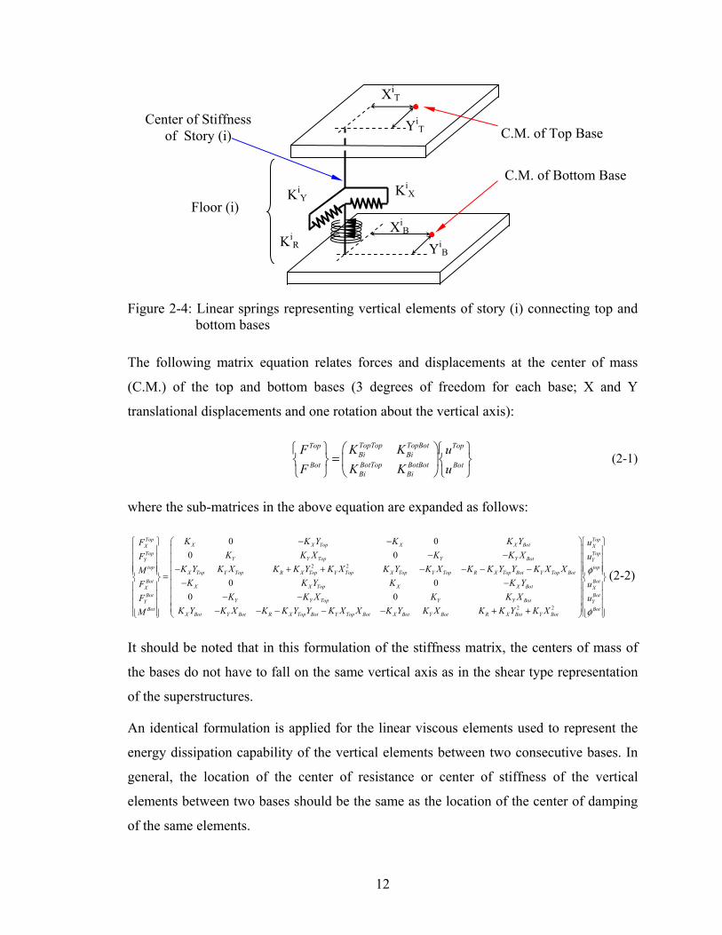
Figure 2-4 shows two consecutive bases, designated as Top and Bottom, interconnected
by columns and walls which are represented by two translational springs and one
rotational spring (about axes X, Y and Z, respectively), all located at the center of
stiffness of the story (or space) between the two bases.
12
Figure 2-4: Linear springs representing vertical elements of story (i) connecting top and bottom bases
The following matrix equation relates forces and displacements at the center of mass
(C.M.) of the top and bottom bases (3 degrees of freedom for each base; X and Y
translational displacements and one rotation about the vertical axis):
TopTop TopBotTop TopBi BiBotTop BotBotBot BotBi Bi
K KF uK KF u
⎛ ⎞⎧ ⎫ ⎧ ⎫=⎨ ⎬ ⎜ ⎟⎨ ⎬
⎩ ⎭ ⎩ ⎭⎝ ⎠ (2-1)
where the sub-matrices in the above equation are expanded as follows:
2 2
0 00 0
0 00 0
TopX X Top X X BotX
TopY Y Top Y Y BotY
topX Top Y Top R X Top Y Top X Top Y Top R X Top Bot Y Top Bot
BotX X Top X X BotX
BotY Y Top Y Y BotY
Bot
K K Y K K YFK K X K K XF
K Y K X K K Y K X K Y K X K K Y Y K X XMK K Y K K YF
K K X K K XFM
− −⎧ ⎫⎪ ⎪ − −⎪ ⎪⎪ ⎪ − + + − − − −⎪ ⎪ =⎨ ⎬ − −⎪ ⎪⎪ ⎪ − −⎪ ⎪⎪ ⎪⎩ ⎭
2 2
TopXTopYtop
BotXBotYBot
X Bot Y Bot R X Top Bot Y Top Bot X Bot Y Bot R X Bot Y Bot
uu
uu
K Y K X K K Y Y K X X K Y K X K K Y K X
φ
φ
⎛ ⎞ ⎧ ⎫⎜ ⎟ ⎪ ⎪⎜ ⎟ ⎪ ⎪⎜ ⎟ ⎪ ⎪⎪ ⎪⎜ ⎟⎨ ⎬⎜ ⎟ ⎪ ⎪⎜ ⎟ ⎪ ⎪⎜ ⎟ ⎪ ⎪⎜ ⎟− − − − − + + ⎪ ⎪⎩ ⎭⎝ ⎠
(2-2)
It should be noted that in this formulation of the stiffness matrix, the centers of mass of
the bases do not have to fall on the same vertical axis as in the shear type representation
of the superstructures.
An identical formulation is applied for the linear viscous elements used to represent the
energy dissipation capability of the vertical elements between two consecutive bases. In
general, the location of the center of resistance or center of stiffness of the vertical
elements between two bases should be the same as the location of the center of damping
of the same elements.
KiX Ki
Y
KiR
XiT
YiT
YiB
XiB
C.M. of Bottom Base
C.M. of Top Base
Floor (i)
Center of Stiffness of Story (i)
13
2.5 Story Stiffness, Center of Stiffness and Center of Damping
The story stiffness and location of the center of stiffness and center of damping may be
calculated if the lateral (horizontal) stiffness of each vertical element is known. Referring
to Figure 2-5, the story horizontal stiffness is described by
, N N
i j i jX x Y y
j jK k K k= =∑ ∑ (2-3)
where KiX and Ki
Y are the resultant stiffness constants along the X and Y directions in
story (i), and kjx , kj
y are the lateral (horizontal) stiffness constants along X and Y
directions of the vertical element (j). The location of the center of stiffness of the floor is
described by:
,
N Nj j
y j x jj ji i
CS CSN Nj j
y xj j
k x k yX Y
k k= =∑ ∑
∑ ∑ (2-4)
where XiCS and Yi
CS are the coordinates of the center of stiffness of story (i) with respect
to the coordinate system xOy as shown in Figure 2-5. Moreover, xj and yj are the
coordinates of vertical element (j) with respect to coordinate system xOy.
The resultant rotational stiffness constant of the story, KiR, is given by:
( )2 2( ) ( )N
i j i j i jR x j CS y j CS r
jK k y Y k x X k= − + − +∑ (2-5)
The resultant damping constants and the location of the center of damping of each story
of the substructure can be calculated in a similar manner by use of equations (2-3) to
(2-5) and replacing the stiffness constants with the damping constants. However, in
general the location of the center of damping is assumed to be the same as the location of
the center of stiffness.
The resultant stiffness and the location of the center of stiffness of each story of the
substructure may be most conveniently calculated by static analysis in computer
programs like ETABS and STAAD. One example of such calculation is presented in

14
Appendix A.
Figure 2-5: Plan view of story (i) and vertical elements connecting two bases.
2.6 Analytical Model and Equations of Motion
The equations of motion of the superstructures (structures above first base) are given by
the following matrix expression:
{ }1 1 1 3 1 3 1b b b b b b b b b b b bN N N N N N N N N N N N B gM u C u K u M R u u× × × × × × × × ×+ + = − + (2-6)
In the above equation, M, C, and K are the combined mass, damping and stiffness
matrices of the superstructure buildings, u is the combined displacement vector of the
superstructure buildings relative to the first base, and R is a transformation matrix which
transfers the first base and ground acceleration vectors from the center of mass of the first
base to the center of mass of each floor of each superstructure. The subscripts in the
equation indicate matrix sizes. Nb is the total number of degrees of freedom of the
superstructures above the first base and is equal to 3 times the number of floors of all
X
Y
Center of Stiffness
yj
yk
xk
xj
Column (j)
O
XCS
YCS
Arbitrary Coordinate System
Column (k)

15
superstructures. The interested reader can find the description of matrix R in Tsopelas et
al. (1994).
The equations of dynamic equilibrium of the isolated structure are given by the following
matrix equation:
{ } 11 11 1 1 1 1
11 1
11 11 1 1 111 1
0 00
0 0
0
T T kB B g B B B
k kk kkBk Bk B B Bk Bk
kB B B NBk kk kkB B Bk Bk NBk
M MR u K uR M R MR M u I u K K u
M u I K K K u
C uC C u fC C C u f
⎡ ⎤ ⎧ ⎡ ⎤ ⎫ ⎡ ⎤ ⎧ ⎫⎪ ⎪ ⎪ ⎪⎢ ⎥ ⎢ ⎥ ⎢ ⎥+ + + +⎨ ⎬ ⎨ ⎬⎢ ⎥ ⎢ ⎥ ⎢ ⎥⎪ ⎪ ⎪ ⎪⎢ ⎥ ⎢ ⎥ ⎢ ⎥+⎣ ⎦ ⎩ ⎣ ⎦ ⎭ ⎣ ⎦ ⎩ ⎭
⎡ ⎤ ⎧ ⎫ ⎧⎪ ⎪ ⎪⎢ ⎥+ +⎨ ⎬ ⎨⎢ ⎥⎪ ⎪⎢ ⎥+⎣ ⎦ ⎩ ⎭ ⎩
0⎫⎪ =⎬
⎪ ⎪⎭
(2-7)
The second (middle) of the three sub-matrix equations in (2-7) is the equation of
equilibrium of the first base, which acts as the interface between the superstructures and
the lower bases. The modified mass matrix in (2-7) is a product of the mass matrix and
the transformation matrices involving R in the following expression:
1
0 0 0 0 00 0 0 0 0
0 0 0 0 0 0
TB
Bk
I M I RR I M I
I M I
⎡ ⎤ ⎡ ⎤ ⎡ ⎤⎢ ⎥ ⎢ ⎥ ⎢ ⎥⎢ ⎥ ⎢ ⎥ ⎢ ⎥⎢ ⎥ ⎢ ⎥ ⎢ ⎥⎣ ⎦ ⎣ ⎦ ⎣ ⎦
(2-8)
where, MB1 is a 3x3 diagonal mass matrix of the first base, MBk is a (Nbs-3)x(Nbs-3) mass
matrix which contains the masses and moments of inertia of the rest of the bases of the
substructure (excluding the first base), and Nbs is the total number of degrees of freedom
of the bases (equal to three times the number of bases). Sub-matrices K11B1, K1k
B1, Kk1B1,
K11B1, Kkk
Bk, C11B1, C1k
B1, Ck1B1, C11
B1, CkkBk are stiffness and damping matrices of the
vertical elements (represented as linear elastic and linear viscous elements) between
bases. Matrices KkkBk and Ckk
Bk also include contributions from linear-elastic and linear-
viscous elements of the isolation system located below at the lowest base (connected

16
between the lowest base and the ground). Moreover, fN is a vector containing the forces
in elements of the isolation system.
Modal reduction for the equations of equilibrium of the superstructure is employed in
accordance with the following equation:
3 3 1i i i ii i inf nf ne ne
u Y× ×
= Φ (2-9)
where, Φi is the ortho-normal modal matrix relative to the mass matrix of superstructure
(i), Yi is the modal displacement vector of superstructure (i) relative to the first base and
nei is the number of eigenvectors of superstructure (i) used in the analysis.
Combining equations (2-6) to (2-9), the following equation is derived. Note that this
equation is written for the case of three bases.
( ) ( ) ( )
( ) ( )
1 1
2 2
3 3 1
11 121 1 1
21 22 11 121 1 2 2 2
21 22 112 2 3 3
2b bs b bs b bs
b bs b bs b b
T
T TB B
B B
B BM N M N M N
B B B
B B B B B
B B B BM N M N M N
I MR YR M R MR M u
M uM u
YC C uC C C C u
C C C u
ξω+ × + + ×
+ × + +
⎛ ⎞ ⎧ ⎫Φ⎜ ⎟ ⎪ ⎪Φ + ⎪ ⎪⎜ ⎟ +⎨ ⎬⎜ ⎟ ⎪ ⎪⎜ ⎟⎜ ⎟ ⎪ ⎪⎝ ⎠ ⎩ ⎭
⎧ ⎫⎛ ⎞⎪ ⎪⎜ ⎟⎪ ⎪⎜ ⎟+ ⎨ ⎬⎜ ⎟+ ⎪ ⎪⎜ ⎟ ⎪ ⎪+⎝ ⎠ ⎩ ⎭( )
( ) ( ) ( )
( ) ( )
{ }
1
2
11 1211 1
21 22 11 1221 1 2 2
21 22 1132 2 3 1
1 13 1
2 2
3 31 3
0
s
b bsb bs b bs
b bs b bs
BB B
BB B B B
BB B B M NM N M N
T
TNB B
gNB B
NB BM N M N
YuK KuK K K KuK K K
MRf R MR M
uf Mf M
ω×
+ ×+ × +
×
+ × + ×
+
⎛ ⎞ ⎧ ⎫⎜ ⎟ ⎪ ⎪
⎪ ⎪⎜ ⎟+ +⎨ ⎬⎜ ⎟+ ⎪ ⎪⎜ ⎟⎜ ⎟ ⎪ ⎪+ ⎩ ⎭⎝ ⎠
⎧ ⎫Φ⎧ ⎫⎪ ⎪⎪ ⎪ +⎪ ⎪ ⎪ ⎪+ = −⎨ ⎬ ⎨ ⎬
⎪ ⎪ ⎪ ⎪⎪ ⎪ ⎪ ⎪⎩ ⎭ ⎩ ⎭ (2-10)
Equation (2-10) may be written as
+ + + =t t t t tM u C u K u f P (2-11)

17
in which subscript t denotes that the equation is valid at time t . Extending Equation
(2-11) to time (t + ∆t), where ∆t is the time step, we have
+ + + + ++ + + =t ∆t t ∆t t ∆t t ∆t t ∆tM u C u K u f P (2-12)
The difference between Equations (2-11) and (2-12) gives the incremental equation of
equilibrium
+ + + + ++ + + = − − − −t ∆t t ∆t t ∆t t ∆t t ∆t t t t tM ∆u C ∆u K ∆u ∆f P M u C u K u f (2-13)
Accordingly, the response of the multiple building superstructure and bases is represented
by the mixed vectors consisting of modal coordinates for the superstructures and vectors
tu , tu , and tu .
2.7 Solution Method
The pseudo-force method is used in the present study as originally adopted in the
program 3D-BASIS by Nagarajaiah et al. (1989). This method has been used for
nonlinear dynamic analysis of shells by Stricklin et al. (1971) and by Darbre and Wolf
(1988) for soil-structure interaction problems. More details and the advantages of this
method in the analysis of seismically isolated structures have been presented by
Nagarajaiah et al. (1989, 1990, 1991a, and 1991b). In the pseudo-force method, the
incremental nonlinear force vector ttf ∆+∆ in Equation (2-13) is unknown. It is, thus,
brought on the right hand side of Equation (2-13) and treated as pseudo-force vector.
2.8 Solution Algorithm
The differential equations of motion are integrated in the incremental form of Equations
2-13. The solution involves two stages:
(i) Solution of the dynamic equations of motion (second-order ordinary
differential equations) using the unconditionally stable (for both positive and
negative tangent stiffness⎯Cheng, 1988) Newmark's constant-average-
acceleration method (Newmark, 1959).

18
(ii) Solution of the first-order ordinary differential equations governing the
nonlinear behavior of the isolation elements using an unconditionally stable
semi-implicit Runge-Kutta method suitable for stiff differential equations
(Rosenbrock, 1964). The solution algorithm of the pseudo force method with
iteration is presented in Table 2-1.
2.8.1 Varying Time Step for Accuracy
The solution algorithm has the option of using a constant time step or variable time step.
For the variable time step option, the time step is reduced from slipt∆ (time step at high
velocities) to a fraction of its value at low velocities to maintain accuracy in sliding
isolated structures. The time step is reduced based on the magnitude of the resultant
velocity at the center of mass of the lower isolation level:
2
1 expstick sliput tB
⎡ ⎤⎛ ⎞∆ = ∆ − −⎢ ⎥⎜ ⎟
⎝ ⎠⎣ ⎦ (2-14)
in which u is the resultant velocity at the center of mass of the lowest base, stickt∆ is the
reduced time step when the base velocity is low ( slipt∆ > stickt∆ > slipt∆ /nl; nl is an integer
to introduce the desired reduction), and B is a constant to define the range of velocity
over which the reduction takes place. It is important to note that the reduction in the time
step is not continuous as indicated by Equation (2-14), but rather at discrete intervals of
velocity. This procedure is adopted for computational efficiency. Equation (2-14) has
been a feature in the 3D-BASIS series of programs (Nagarajaiah et al, 1989, 1990, 1991a,
and 1991b).

19
Table 2-1: Solution algorithm
A. Initial Conditions: 1. Form stiffness K , mass M , and damping matrices C~ . Initialize 0u~ , 0
~u , and 0~u .
2. Select time step ∆t, set parameters δ = 0.25 and θ = 0.5, and calculate the integration constants:
⎟⎠⎞
⎜⎝⎛ −⋅∆==
∆⋅==
∆⋅=
∆⋅= 1
2;;;
21;1;1
6543221 δθ
δθ
δθ
δδδtaa
taa
ta
ta
3. Form the effective stiffness matrix KCMK ~~~41
* +⋅+⋅= aa 4. Triangularize K* using Gaussian elimination (only if the time step is different from the
previous step). B. Iteration at each time step: 1. Assume the pseudo-force 0=∆ ∆+
ittf in iteration i = 1.
2. Calculate the effective load vector at time t + ∆t: ( ) ( )tttt
itttttt aaaa uuCuuMfPP ~~~~~~~
6532* ⋅+⋅+⋅+⋅⋅+∆−∆= ∆+∆+∆+
( )tttttt fuKuCuMPP tt +⋅+⋅+⋅−=∆ ∆+∆+~~~~~~~~
3. Solve for displacements at time t+∆t: **tt
itt ∆+∆+ =∆⋅ PuK
4. Update the state of motion at time t+∆t: tt
ittttt aaa uuuuu ~~~~~
321 ⋅−⋅−∆⋅+= ∆+∆+
tti
ttttt aaa uuuuu ~~~~~654 ⋅−⋅−∆⋅+= ∆+∆+
ittttt ∆+∆+ ∆+= uuu ~~~
5. Compute the forces mobilized in each isolation element following the steps: 5a. Calculate bearing axial forces at iteration (i) using acceleration distribution at time
(t). [Axial forces are calculated using an iterative process. First, the isolators which undergo uplift are identified using the method described in Section 3.4. Then, axial loads in each isolator are updated and if there are additional isolators that uplift then an iteration process takes place until it converges.]
5b. Compute the state of motion at each bearing. 5c. Solve the first-order ODEs, using semi-implicit Runge-Kutta method, to evaluate
the variable Zit+∆t used in the nonlinear force equations at each bearing. [For the
calculation of the Zit+∆t the average velocity between the previous and current time
steps are used (Vt + Vit+∆t)/2].
6. Compute the resultant nonlinear force vector of the isolation system, 1+∆+∆ i
ttf . [The nonlinear forces are with respect to the C.M. of the base that the isolators are located.]
7. Compute :MomentMaxref
Errori
tti
tt
..
1∆+
+∆+ ∆−∆
=ff
, where ||.|| is the Euclidean norm
8. If Error ≥ Tolerance, further iteration is needed, iterate starting form step B-1 and use 1+∆+∆ i
ttf as the pseudo-force and the state of motion at time t, tu~ , tu~ , and tu~ . 9. If Error ≤ Tolerance, no further iteration is needed, update the nonlinear force vector:

20
1+∆+∆+ ∆+= i
ttttt fff 10. Reset time step if necessary (the velocity of the lowest isolation base is used in the
criteria of Section 2.4.1) 11. GoTo Step B-1 if the time step is not reset or GoTo A-2 if the time step is reset.

21
SECTION 3
ENHANCEMENTS INTRODUCED IN 3D-BASIS-ME-MB
3.1 Introduction
Program 3D-BASIS-ME-MB offers the following new features:
1. Analyzes a more complex configuration as illustrated in Figure 1-2. In this
configuration the structure consists of three parts:
• Superstructure, consisting of up to 5 separate superstructures. Each is modeled as
having rigid floors with three degrees of freedom each (two translations and one
rotation). The input data consists of the floor mass, moment of inertia and location
of centers of mass, and shear stiffness, torsional stiffness and center of resistance
per story. Alternatively, the input data for representing the stiffness of each part of
the superstructure are in terms of mode shapes and frequencies obtained from
analysis of a detailed model in another program like SAP2000 or ETABS.
• Substructure consisting of up to 5 bases above the lowest isolation interface.
Isolators are located at each of the 5 bases. Each base is represented as a rigid
floor with 3 degrees of freedom. The mass, moment of inertia and location of
center of mass of each floor is input. The stiffness characteristics of the
substructure are input in a manner similar to that of each part of the
superstructure.
• Isolators and dampers that may be located at each base of the substructure. Each
isolator and damper is explicitly modeled in terms of its location, orientation and
constitutive relation.
2. The isolation system has the following new elements:
• The new XY-FP bearing capable of sustaining tension is represented (Roussis and
Constantinou, 2005). The orientation of the bearing may be in any arbitrary
direction with the respect to the global reference frame.
• The existing viscous damper element is modified to have a more general

22
constitutive relation and to have capability for placement at an arbitrary direction
with respect to the global reference frame.
3. Overturning moment effects are captured in a more complex and accurate way. The
axial load on each isolator is calculated at each time step through a procedure
described below in Section 3.4 that relates the instantaneous floor inertia forces to the
axial load on the bearings. This relation can be exactly derived in a static analysis
model of the complete structural system (say in a program like SAP2000 or ETABS)
including cases in which uplift occurs. When bearing uplift occurs, the program
returns zero axial bearing force for the bearings which uplift and redistributes axial
forces to the other bearings so that equilibrium in the vertical direction is satisfied.
4. Program output is streamlined for easy assessment of performance of the structural
system. Specifically, floor response spectra are calculated and exported to excel files
for viewing.
3.2 Element for the Uplift-Restraining XY-FP Isolator
Force-displacement constitutive relationship The principles of operation and mathematical model of the newly introduced XY-FP
isolator have been established by Roussis and Constantinou (2005).
Based on the Friction-Pendulum principle (Zayas et al., 1987; Mokha et al., 1988), the
XY-FP isolator consists of two orthogonal concave stainless steel-faced beams
interconnected through a sliding mechanism that permits tension to develop in the
bearing, thereby preventing potential uplift (Figure 3-1). Under the imposed constraint to
remain mutually perpendicular (except for small rotation about the vertical axis), the two
opposing beams can move independently relative to each other to form a bi-directional
(XY) motion mechanism. For a detailed description of the XY-FP isolator, the reader is
referred to Roussis and Constantinou (2005).

23
Figure 3-1: Three-dimensional view of the uplift-restraining XY-FP isolator.
Neglecting the effect of lateral force on friction force, the force-displacement constitutive
relationship in the local co-ordinate system is given collectively by
1 1 111
222 2 2
sgn( )0000 sgn( )
F U UNN RNN RF U U
µµ
⎧ ⎫⎡ ⎤⎧ ⎫ ⎧ ⎫⎡ ⎤ ⎪ ⎪= +⎨ ⎬ ⎨ ⎬ ⎨ ⎬⎢ ⎥⎢ ⎥⎪ ⎪⎣ ⎦⎩ ⎭ ⎩ ⎭ ⎣ ⎦ ⎩ ⎭
(3-1)
where 1R and 2R are the radii of curvature of the lower and upper concave beams,
respectively (minus the small height of the pivot point to the concave surface of the
beam); 1µ and 2µ are the associated sliding friction coefficients; 1U and 2U are the
displacements in local axis 1 and 2, respectively; N is the normal force on the bearing,
positive when compressive; and sgn( )iU is the signum function operating on the sliding
velocities.
Equation (3-1) describes the resisting force of the isolator along the i -direction assuming
small angles of rotation ϕ (linearized form). The resisting force is synthesized by two
components, one representing the pendulum effect associated with a restoring force (in
the case of compressive normal load), and the other representing the contribution of
friction developed at the sliding interface.
Having defined the constitutive relation of the bearing with respect to the local co-
ordinate system, the corresponding force-displacement relationship in the global co-
ordinate system can be readily derived as

24
1
2
cos sinsin cos
Tx
y
F FF F
θ θθ θ
⎧ ⎫ ⎧ ⎫⎡ ⎤=⎨ ⎬ ⎨ ⎬⎢ ⎥−⎣ ⎦ ⎩ ⎭⎩ ⎭
(3-2)
Isolator normal force In general, the normal force on the isolation bearing is a fast-varying function of time due
to the effect of vertical earthquake motion and global overturning moment. For a
vertically rigid superstructure, the normal force on the bearing at any given time is
synthesized by
1 gv OMu NN Wg W
⎛ ⎞= + +⎜ ⎟
⎝ ⎠ (3-3)
where W is the weight acting on the isolator; gvu is the vertical ground acceleration
(positive when the direction is upwards); and OMN is the additional axial force due to
overturning moment effects (positive when compressive).
Evaluation of the bearing normal force according to Equation (3-3) is of utmost
importance for the accuracy of the XY-FP model. The fluctuation in the bearing axial
force caused by the vertical component of ground motion and overturning moments can
be large enough to cause reversal of the axial force from compression to tension.
Coefficient of sliding friction The coefficient of sliding friction mobilized on a typical sliding bearing interface is
modeled by the following equation (Constantinou et al., 1990):
max max min( ) a us f f f eµ −= − − (3-4)
where the coefficient of sliding friction sµ ranges from minf , at very low velocities of
sliding, to maxf , at large velocities; u is the velocity of sliding; and a is a constant,
having units of time per unit length, that controls the variation of the coefficient of
friction with velocity. The dependency of the coefficient of friction on velocity is
illustrated in Figure 3-2(a).

25
Figure 3-2: Variation of coefficient of friction with (a) velocity of sliding; and (b) bearing contact pressure.
In general, parameters maxf , minf , and a are functions of bearing pressure and temperature.
However, the dependency of minf and a on pressure is insignificant (compared with that
of maxf ) and can be neglected (Tsopelas et al., 1994). A representative expression
describing the variation of parameter maxf with pressure is given by
max max 0 max 0 max p( ) tanh( )f f f f pε= − − (3-5)
where parameter maxf ranges from max 0f , at almost zero pressure, to max pf , at very high
pressure; p is the bearing contact pressure; and ε is a constant that controls the variation
of maxf between very low and very high pressures. Figure 3-2(b) presents the assumed
variation of friction parameter maxf with pressure, which is typical of the behavior of
sliding bearings (Soong and Constantinou, 1994).
Model for XY-FP isolator in 3D-BASIS-ME-MB
To accommodate the mechanical behavior of the new XY-FP isolator, a new hysteretic
element was incorporated into 3D-BASIS-ME-MB. The new element is synthesized by
two independent uniaxial hysteretic elements allowing different frictional interface
properties along the principal isolator directions (Roussis and Constantinou, 2005). It
should be emphasized that, contrary to the element representing the conventional FP
isolator, the new element is capable of accommodating the uplift-restraint property of the
26
XY-FP isolator by allowing continuous transition of the bearing axial force from
compression to tension and vice versa. Moreover, the new element can assume different
frictional interface properties under compressive and tensile isolator normal force.
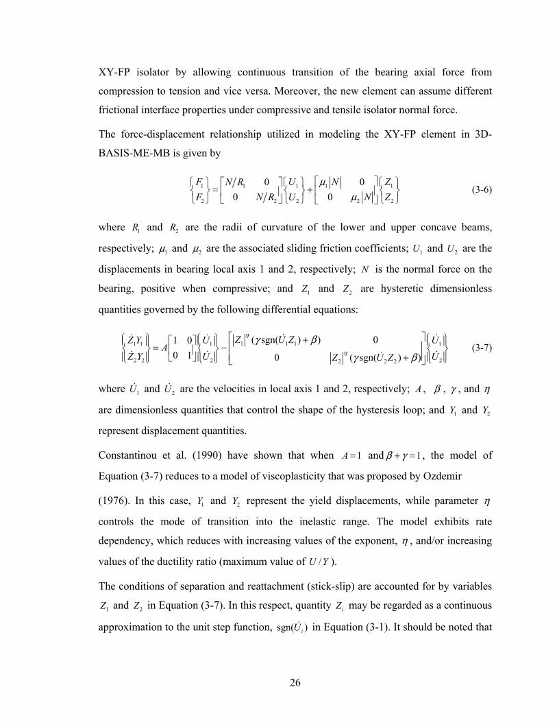
The force-displacement relationship utilized in modeling the XY-FP element in 3D-
BASIS-ME-MB is given by
1 1 111
222 2 2
0000
F U ZNN RNN RF U Z
µµ
⎡ ⎤⎧ ⎫ ⎧ ⎫ ⎧ ⎫⎡ ⎤= +⎨ ⎬ ⎨ ⎬ ⎨ ⎬⎢ ⎥⎢ ⎥⎣ ⎦⎩ ⎭ ⎩ ⎭ ⎩ ⎭⎣ ⎦
(3-6)
where 1R and 2R are the radii of curvature of the lower and upper concave beams,
respectively; 1µ and 2µ are the associated sliding friction coefficients; 1U and 2U are the
displacements in bearing local axis 1 and 2, respectively; N is the normal force on the
bearing, positive when compressive; and 1Z and 2Z are hysteretic dimensionless
quantities governed by the following differential equations:
1 1 11 1 1 1
2 2 2 22 2 2
( sgn( ) ) 01 00 1 0 ( sgn( ) )
Z U ZZ Y U UA
Z Y U UZ U Z
η
η
γ β
γ β
⎡ ⎤⎧ ⎫ ⎧ ⎫ ⎧ ⎫+⎡ ⎤⎪ ⎪ ⎪ ⎪ ⎪ ⎪⎢ ⎥= −⎨ ⎬ ⎨ ⎬ ⎨ ⎬⎢ ⎥⎢ ⎥+⎣ ⎦⎪ ⎪ ⎪ ⎪ ⎪ ⎪⎩ ⎭ ⎩ ⎭ ⎩ ⎭⎣ ⎦
(3-7)
where 1U and 2U are the velocities in local axis 1 and 2, respectively; A , β , γ , and η
are dimensionless quantities that control the shape of the hysteresis loop; and 1Y and 2Y
represent displacement quantities.
Constantinou et al. (1990) have shown that when 1A = and 1β γ+ = , the model of
Equation (3-7) reduces to a model of viscoplasticity that was proposed by Ozdemir
(1976). In this case, 1Y and 2Y represent the yield displacements, while parameter η
controls the mode of transition into the inelastic range. The model exhibits rate
dependency, which reduces with increasing values of the exponent, η , and/or increasing
values of the ductility ratio (maximum value of /U Y ).
The conditions of separation and reattachment (stick-slip) are accounted for by variables
1Z and 2Z in Equation (3-7). In this respect, quantity iZ may be regarded as a continuous
approximation to the unit step function, sgn( )iU in Equation (3-1). It should be noted that

27
= 1iZ ± during the sliding phase, whereas 1iZ < during the sticking phase (elastic
behavior with very high stiffness).
A limitation of the employed plasticity model is its inability to reproduce truly rigid-
plastic behavior. However, since Teflon-steel interfaces undergo very small elastic
displacement before sliding, a small value of yield displacement Y , in the range of 0.13
to 0.50 mm (0.005 to 0.02 in.), can be reasonably assumed (larger values can also be
justified on the basis of actual bearing behavior), and hence the viscoplasticity model can
be used (Constantinou et al., 1990). The model exhibits insignificant rate dependency for
such low yield displacement and resulting ductility ratio, and for parameter values of
2η = , 0.1β = , and 0.9γ = suggested by Constantinou et al. (1990).
It should be emphasized that Equation (3-7) is uncoupled, representing two independent
uniaxial hysteretic elements along the principal directions of the isolator. Accordingly,
the biaxial interaction between forces in the two orthogonal directions is nonexistent,
rendering the interaction surface to be square, as opposed to the circular interaction
surface for the biaxial behavior of the spherical FP isolator (Figure 3-3).
Figure 3-3: Force interaction curves for XY-FP and FP isolators.
The model in 3D-BASIS-ME-MB accounts for the variability of the normal force through
Equation (3-3). The additional axial force due to overturning moment effects, OMN , in
Equation (3-3) is calculated through the procedure presented in Section 3.4.1. Moreover,
the dependency of the coefficient of friction on sliding velocity and bearing pressure is
explicitly modeled according to Equations (3-4) and (3-5), respectively.

28
3.3 Element for Viscous Damper
Program 3D-BASIS-ME-MB has two elements for modeling viscous damper behavior.
Both are uni-axial elements that can be placed in an arbitrary direction with respect to the
global co-ordinate system.
Linear/nonlinear viscous element
This element has the following constitutive relation:
sgn( )F C U Uα
= (3-8)
Where F is the force along the axis of the damper, U is the relative velocity of the one
end of the damper with respect to the other end along the axis of the damper, C is the
damper constant, and α is the power constant. For 1α = , linear viscous behavior is
obtained.
General nonlinear viscous element
This element has the following constitutive relation:
( )( )
1
2
01 1 12
02 2 max 12
sgn( ) for
sgn( ) for
F C U U U VF
F C U U F U V
α
α
⎧ + ≤⎪= ⎨⎪ + ≤ >⎩
(3-9)
which is portrayed in Figure 3-4. This relation distinguishes between two ranges of
velocity, separated by velocity 12V , in each of which a different constitutive relation
applies. This relation is the linear or nonlinear viscous relation with an added friction
force ( 01F and 02F ) that simulates friction in the seals of viscous dampers. Moreover, the
force output of the element is bound by force limit maxF . Equation (3-9) represents the
novelty introduced in 3D-BASIS-ME-MB. It allows for a more realistic representation of
viscous damper behavior.

29
Figure 3-4: Graphical representation of the constitutive relation for the general nonlinear viscous element.
3.4 Construction of Relation between Inertial Forces and Axial
Bearing Loads
3.4.1 Case of No Isolator Uplift
In order to account for the variability of axial forces in the isolation bearings due to
overturning moment effects, 3D-BASIS-ME was modified to include a direct relationship
between floor inertia forces and additional axial load on bearings (Roussis and
Constantinou, 2005). At each time step of integration (beginning of time step), the
horizontal inertia forces, { }IF , are calculated from the floor accelerations and multiplied
by a coefficient matrix, [ ]T , to obtain the corresponding change of vertical loads on the
bearings due to overturning moment effects, { }OMN . The additional vertical load can be
expressed as
{ } [ ]{ }OM IN T F= (3-10)
where { } ,1 ,2 ,1
T
OM OM OM OM nnN N N N
×⎡ ⎤= ⎣ ⎦… is the vector of bearing axial forces;
[ ] 2n iT
× is a coefficient matrix relating additional bearing axial forces to floor inertia
forces; { } , , ,1 ,12 1
T
I I ix I iy I x I yiF F F F F
×⎡ ⎤= ⎣ ⎦… is the vector of inertia forces at every

30
floor level and isolated-base level; n is the number of bearings; and i is three times the
total number of floors plus the number of isolated bases (model might have more than
one superstructure/building), or in other words i is equal to the total number of dynamic
degrees of freedom considered in the structural model (X and Y translation and Rotation
at the C.M. of every slab in the structural model).
The coefficient matrix, [ ]T , is evaluated externally by other computer programs (e.g.,
SAP2000 or ETABS) and imported into program 3D-BASIS-ME-MB. It shall be
calculated from linear static analyses of the structure supported on hinge supports and
subjected to horizontally acting unit loads at the C.M. of the different floor levels. For
example, the -thi column of matrix [ ]T is calculated as the local frame column loads
upon application of a unit lateral force at the center of mass of the -thi floor, with the
lateral forces of the remaining floors being zero. It should be noted that construction of
matrix [ ]T is not sufficient to describe the distribution of axial force on the bearings
when uplift occurs.
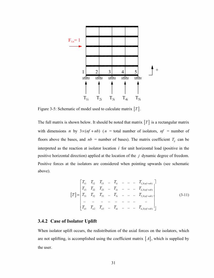
In the case of a multi-story structure on five isolators as shown in Figure 3-5, and
assuming that no uplift occurs, matrix [ ]T , supplied in file TMATRIX.DAT, is
calculated by static analysis (e.g., SAP2000; ETABS; or STAAD, Research Engineers
International, 2002) using a model in which the bearings are modeled as pins or as a
combinations of pins and rollers. Care should be exercised in modeling the isolators so
that the horizontal component of reactions does not incorrectly affect the balance of
moments. For example, in cases in which all isolators are at the same level (as in the case
illustrated in Figure 3-5), the bearings can be arbitrarily represented as pins or rollers
since the resultant horizontal reaction is always the same. However, in the case of split
level isolation system, the horizontal reaction distribution to the various levels needs to
be properly considered. This will become apparent in one of the two examples in this
manual.
The unit horizontal load is applied at the i th degree of freedom and the reactions at
isolator locations constitute the i th column of the matrix [ ]T .
31
Figure 3-5: Schematic of model used to calculate matrix [ ]T .
The full matrix is shown below. It should be noted that matrix [ ]T is a rectangular matrix
with dimensions n by 3 ( )nf nb× + ( n = total number of isolators, nf = number of
floors above the bases, and nb = number of bases). The matrix coefficient ijT can be
interpreted as the reaction at isolator location i for unit horizontal load (positive in the
positive horizontal direction) applied at the location of the j dynamic degree of freedom.
Positive forces at the isolators are considered when pointing upwards (see schematic
above).
[ ]
11 12 13 1 1,3( )
21 22 23 2 2,3( )
31 32 33 3 3,3( )
1 2 3 ,3( )
.. .. .. ..
.. .. .. ..
.. .. .. .. ... .. .. .. .. .. .. .. ..
.. .. .. ..
i nf nb
i nf nb
i nf nb
n n n ni n nf nb
T T T T TT T T T TT T T T TT
T T T T T
+
+
+
+
⎡ ⎤⎢ ⎥⎢ ⎥⎢ ⎥=⎢ ⎥⎢ ⎥⎢ ⎥⎣ ⎦
(3-11)
3.4.2 Case of Isolator Uplift
When isolator uplift occurs, the redistribution of the axial forces on the isolators, which
are not uplifting, is accomplished using the coefficient matrix [ ]A , which is supplied by
the user.

32
The coefficient matrix, [ ]A , is evaluated externally by other computer programs (e.g.,
SAP2000, ETABS or STAAD) and imported into program 3D-BASIS-ME-MB. It is
calculated by linear static analyses of the structure loaded with unit vertical loads at the
location of an isolator (which is removed for the analysis). The calculated reactions at
each location of the remaining isolators constitute the coefficients of a column of matrix
[ ]A . The non-uplifting isolators must be modeled as pins or rollers using the same
concepts as for the case of construction of the [ ]T matrix. However, in this case the
errors introduced by incorrect distribution of horizontal reactions in split level isolation
systems are less important and all isolators could be modeled as pins for simplicity. The
analysis needs to be repeated for each isolator. For example, the i th column of matrix [ ]A
is calculated as shown in the schematic below:
Figure 3-6: Schematic of model used to calculate matrix [ ]A .
The full matrix [ ]A is presented in (3-12). It should be noted that matrix [ ]A is square,
with a unit diagonal, non-symmetric matrix with dimensions n by n ( n = total number
of isolators). The matrix coefficient ijA can be interpreted as the reaction at isolator
location i for unit vertical load applied at the isolator location j (where isolator j has

33
been removed).
[ ]
12 13 1 1
21 23 2 2
31 32 3 3
1 2 3
1 2 3
1 .. ..1 .. ..
1 .. .... .. .. .. .. .. ..
.. 1 .... .. .. .. .. .. ..
.. ..
i n
i n
i n
i i i in
n n n ni nn
A A A AA A A AA A A A
AA A A A
A A A A A
⎡ ⎤⎢ ⎥⎢ ⎥⎢ ⎥⎢ ⎥= ⎢ ⎥⎢ ⎥⎢ ⎥⎢ ⎥⎢ ⎥⎣ ⎦
(3-12)
The axial loads on the isolators when a number of them uplift (a = number of isolators
which uplift) is given by equation (3-13).
0
0
a aa ab aOM
b b ba bbuplf OM
N A A XN N A A
⎧ ⎫⎧ ⎫ ⎡ ⎤ ⎧ ⎫= +⎨ ⎬ ⎨ ⎬ ⎨ ⎬⎢ ⎥
⎣ ⎦ ⎩ ⎭⎩ ⎭ ⎩ ⎭ (3-13)
where, buplfN contains the axial loads on the isolators which do not uplift,
{ } Ta bOM OM OMN N N⎡ ⎤= ⎣ ⎦ is the vector containing the normal loads on the bearings as
calculated by equation (3-10) rearranged in such a way that the terms corresponding to
isolators that uplift are located in the first a positions of the vector, matrix [ ]A is the
coefficient matrix obtained as described above rearranged in such a way that the columns
and rows corresponding to isolators that uplift and those that do not uplift, and { }aX is a
vector, which is evaluated by solving the system of linear algebraic equations in equation
(3-14).
{ } { }a aa aOMN A X⎡ ⎤− = ⎣ ⎦ (3-14)
3.4.3 User Supplied Information
In the case where it is desired to account for overturning moment effects, the user needs
to provide the following information in program 3D-BASIS-ME-MB:
• For the uplift-restraining XY-FP isolators (C.7.8 in Section 5): matrix [ ]T
34
supplied in file TMATRIX.DAT.
• For flat sliding and FPS isolators (C.7.5 and C.7.8 in Section 5): matrix [ ]T
supplied in file TMATRIX.DAT and matrix [ ]A supplied in file
TMATRIXUPLF.DAT.
All other calculations are internally done in the program.
It should be noted that when the user supplies a zero matrix [T] and a unit matrix [A], the
result is constant axial load on all bearings due to overturning moment effects.
35
SECTION 4
VERIFICATION EXAMPLES
4.1 Introduction
Two examples are used in the verification of program 3D-BASIS-ME-MB. In both cases
the analyzed structure is seismically isolated with Friction Pendulum bearings and is
excited under conditions of bearing uplift. This represents the most extreme condition
that bearings are subjected to and is a case of much interest in verifying the capabilities of
analysis software. It may be mentioned in passing that the verification examples include a
great deal of information on how to use the program and provide further clarifications on
practical topics that are inherently difficult to explain in the abstract.
The first example is a 7-story model structure that was tested on the shake table at the
University at Buffalo (Al-Hussaini et al, 1994). This example is of much interest since it
was studied in verification examples of program SAP2000 (Scheller and Constantinou,
1999; and Computers and Structures, 2003). Results of analysis by program 3D-BASIS-
ME-MB and by program ABAQUS (ABAQUS, 2004) are compared to experimental
results.
The second example is a two-tower multi-story structure with a split seismic-isolation-
system level. The isolation system again consists of Friction Pendulum bearings and the
structure is excited under conditions of bearing uplift. Results of analysis by program 3D-
BASIS-ME-MB are compared to results produced by program ABAQUS.
4.2 Verification Example 1: Seven-Story Isolated Model
Figure 4-1 illustrates the 7-story model of this verification study. It was tested by Al-
Hussaini et al (1994). Additional information on this model may be found in Scheller and
Constantinou (1999), where experimental results in electronic format are available, and in
Computers and Structures (2004).

36
Figure 4-1: Schematic of 7-story model tested on shake table (Al Hussaini et al, 1994).
The isolation system of this model structure consisted of eight Friction Pendulum
bearings with radius of curvature equal to 9.75 in. and coefficient of friction in high-
velocity motion equal to 0.06. Total weight on the eight bearings was 47.5 kip. In one test
in configuration MFUIS with El Centro motion, component S00E, scaled to peak
acceleration of 0.58g, the model experienced uplift. This case is modeled in programs
3D-BASIS-ME-MB and ABAQUS and compared to experimental results.
The input file in program 3D-BASIS-ME-MB is presented in Appendix B. Moreover,
Appendix C describes the construction of matrices [T] and [A].
The Friction Pendulum bearings were modeled in program ABAQUS by modeling
coincident nodes at the position of each isolator. One node was defined as part of the
superstructure, whilst the other was used in the definition of the substructure or

37
foundations. The bearing was then modeled using a contact feature known as an
analytical rigid surface that creates master/slave sliding contact between the coincident
nodes, as shown in Figure 4-2. This feature allowed each component of the bearing to be
explicitly modeled. One node was selected as the master and the concave sliding surface
of the bearing was created at this node by defining an axis of revolution that sets up a
local coordinate cylindrical coordinate system, in (r,z) space. The sliding surface was
then created by defining the coordinates of three points in this local coordinate system,
one at the center of curvature of the sliding surface, one on the axis of revolution, at the
surface of the bearing and one at an arbitrary point on the sliding surface, at or beyond
the displacement capacity of the bearing. The convex slider was defined simply as the
slave node. The articulation of the slider in the housing plate socket, in effect a pinned
connection was defined implicitly, since the analytical surface feature activates only
translational degrees of freedom at nodes connected to it. The concave sliding surface is a
smooth, continuous surface, which is important for contact since it avoids the inherent
discontinuities that arise when using a surface defined with discrete facets and was
modeled with a radius of 9.75 inch. The interaction between the slider and sliding surface
was defined using the same friction model described in Al-Hussaini et al (1994) and
Scheller and Constantinou (1999) for this structure.
Note that the representation of the slider shown in Figure 4-2 makes no contribution to
the physical response of the bearing model and is purely for visualization. By default
separation of the coincident nodes and hence bearing uplift is allowed. However,
additional features can be employed to allow transmittal of tension forces normal to the
bearing, as well as limit the bearing displacement, e.g. due to the presence of the
retaining ring on the concave surface, as required. This modeling technique could be
readily adapted to model the XY-FP isolator described in Section 3.2 of this report.
Further details on the modeling of structures isolated with Friction Pendulum bearings in
ABAQUS may be found in Clarke et al. (2005).

38
Figure 4-2: View of Friction Pendulum bearing modeled in ABAQUS.
Results of program 3D-BASIS-ME-MB plotted against experimental results are
presented in Appendix D and results of program ABAQUS plotted against experimental
results are presented in Appendix E.
It may be observed in the results of Appendix D that program 3D-BASIS-ME-MB
predicts very well the experimental response, with the exception of the hysteretic loops
for the interior bearing. However, in this case the gravity load on the bearings was not
measured and it was assumed to be the one based on tributary area distribution, thus
leading to differences in the calculated and measured shear forces and displacements in
the bearing. Assumption of different gravity load distribution leads to different calculated
response that is closer to the experimental response.
The response calculated by program ABAQUS also compares very well with the
experimental response. However, it may be noted that certain predictions of program 3D-
BASIS-ME-MB are slightly better than those of program ABAQUS (i.e., shear force in
uplifted bearings and drift). This may be attributed to the fact that the model of the
superstructure in program 3D-BASIS-ME-MB was adjusted to better fit the
experimentally identified modal properties of the model.
4.3 Verification Example 2: Two-Tower, Split-Level Isolated Structure
The second example concerns a two-tower multi-story structure with a split seismic-

39
isolation-system level. The model geometry is illustrated in the schematic of Figure 4-3.
The isolation system consists of Friction Pendulum bearings with radius of curvature
equal to 169 in. and coefficient of friction in high-velocity motion equal to 0.07. The
frictional model used along with the associated isolator properties are depicted in Figure
4-4. Appendix F presents schematics that describe the two-tower verification model in
terms of section properties, model masses, and weight on bearings.
The first two modes of the structure (with isolators represented as pins) were assumed to
have damping ratio equal to 2% of critical. Damping in the remaining modes was
represented by the Rayleigh approach.
Figure 4-3: Schematic of two-tower, split-level isolated structure.

40
Figure 4-4: Frictional model used for FP isolators of two-tower structure.
The seismic excitation consists of the horizontal component acceleration history shown in
Figure 4-5. Appendix G presents the input file in program 3D-BASIS-ME-MB and
Appendix H describes the construction of matrices [ ]T and [ ]A . Appendix I describes
the analysis that resulted in the information on stiffness, etc. for input to program 3D-
BASIS-ME-MB to describe the superstructure. Appendix J presents a comparison of
results obtained with programs 3D-BASIS-ME-MB and ABAQUS. These results are for
the case in which the coefficient of friction fmax=0.07 as presented in the description of
the model in Appendix F.
HORIZONTAL ACCELERATION INPUT HISTORY
-0.4
-0.3
-0.2
-0.1
0
0.1
0.2
0.3
0.4
0.5
0 5 10 15 20 25 30 35 40 45TIME (sec)
AC
CEL
ERA
TIO
N (g
)
Figure 4-5: Horizontal ground acceleration history in two-tower model.

41
In comparing the results obtained by programs ABAQUS and 3D-BASIS-ME-MB, it is
important to note that the analyzed structure experiences considerable bearing uplift. As
an example, Figure 4-6 presents the uplift displacement history calculated in ABAQUS
for isolator No. 2 (similar behavior was calculated for bearing 3 and to a lesser extent for
bearings 5 and 6-those directly below the two towers). The maximum uplift displacement
is about 0.45 inch and the duration of each uplift episode is about 0.5 second. That is, the
analyzed structure is in a state of rocking mode, which can be accurately captured only in
an analysis in which geometric nonlinearities are accounted for. Nevertheless, the results
obtained by program 3D-BASIS-ME-MB, which does not have geometric nonlinearity
capabilities, favorably compare to those obtained by program ABAQUS.
ISOLATOR 2 UPLIFT DISPLACEMENT
-0.050.000.050.100.150.200.250.300.350.400.450.50
5 10 15 20 25TIME (sec)
DIS
PLA
CEM
ENT
(inch
)
Figure 4-6: Uplift displacement history of isolator 2 as predicted in ABAQUS.
The following observations may be made in the comparison of results in Appendix J:
1. The bearing displacement histories appear different in the predictions of the two
programs. The differences are attributed to the tendency of program ABAQUS to
predict more permanent displacement. A likely explanation for this behavior are small
differences in modeling the velocity dependence of the coefficient of friction in the
two programs and differences in modeling frictional behavior (viscoplasticity-based
model in 3D-BASIS-ME-MB and direct friction model in ABAQUS). While these
differences in modeling are typically insignificant in high velocity motions, they are
important in low velocity motions as those in this example. The bearing displacement

42
history compared more favorably when the input excitation was scaled up so that the
predicted displacements increased substantially (however, the uplift displacements
also increased to unrealistic levels).
2. Force-displacement loops of individual bearings and of the isolation system at the two
levels compare well in the predictions of the two programs. Particularly interesting
are the loops for isolators No.2 and 3, which indicate that the two bearings experience
much more uplift than any of the other bearings. Nevertheless, the predictions of
program 3D-BASIS-ME-MB favorably compares to those of the much more
sophisticated program ABAQUS.
3. The drift history predicted by 3D-BASIS-ME-MB for the bottom story of the 4-story
tower on the right compare very well with those of ABAQUS. However, the
comparison is not as good for the drift history predicted for the bottom story of the 3-
story tower on the left. This is the result of the significant uplift experienced by
isolators No. 2 and 3 and the resulting rocking of the left tower. The results on drift
presented for ABAQUS include the rigid body rocking effect, whereas those of 3D-
BASIS-ME-MB do not. The rigid body contribution to drift (difference in
displacement between top and bottom of story) is as much as 0.45x15/27.5=0.25 inch,
where 0.45 inch is the maximum uplift displacement, 15 feet is the story height and
27.5 feet is the span between the uplifting bearings.
4. The predictions of the two programs for the top floor accelerations of the two towers
compare well, although program 3D-BASIS-ME-MB predicts more acceleration than
program ABAQUS. This appears as a paradox given that program 3D-BASIS-ME-
MB does not account for the additional acceleration due to the rigid body, rocking
motion effect when uplift occurs. However, program ABAQUS with its geometric
nonlinearity capabilities captures the effects of rocking on reducing the inertia effects
due to lengthening of the period of oscillations, resulting in a canceling of the effects.
5. Predictions of brace forces in the two programs compare well, although program 3D-
BASIS-ME-MB appears to over-predict the force. There are two reasons contributing
to this difference. First, program 3D-BASIS-ME-MB does not account for period
lengthening and thus reduction of inertia effects as the towers undergo rocking.

43
Second, and likely the major contributor to the difference, is that the brace force was
not directly calculated in 3D-BASIS-ME-MB but rather extracted from the history of
story shear as follows (in a separate analysis following analysis in 3D-BASIS-ME-
MB): the contribution to the story shear from column deformation was subtracted
(assuming shear type behavior) and the remaining force was resolved along the brace
axis assuming truss behavior.
Additional results for the two-tower example are presented in Appendix K where all
parameters of the analyzed model are the same except that the friction coefficient fmax is
0.04 rather than 0.07. This situation results in larger bearing displacements and in
reduction of the duration and amplitude of uplift displacements (reduced to a peak of
about 0.3 inch and of duration of about 0.3 second for each uplift episode). The results of
analysis by the two programs presented in Appendix K compare more favorably than
those of Appendix J. Apparently, the amount and duration of bearing uplift episodes is
important in the accurate prediction of response by program 3D-BASIS-ME-MB. This
statement is further collaborated by the excellent comparison of results predicted by the
two programs in the case of the tested 7-story model, a case in which the duration and
amount of uplift were very small.

45
SECTION 5
USER’S GUIDE TO PROGRAM 3D-BASIS-ME-MB
A.1 INPUT FORMAT FOR 3D-BASIS-ME-MB The program 3D-BASIS-ME-MB requires the input file with name 3DBMEMB.DAT and the earthquake excitation file names WAVEX.DAT, WAVEY.DAT and WAVEZ.DAT. The main output file is 3DBMEMB.OUT.
The program produces other output files: (i) output files for each isolated base named [ISOLBASE_No 1.OUT] containing time histories of the accelerations and displacements of the base at the C.M. of the base; (ii) output files for each superstructure/building named [1001], [1002], etc., containing time histories of the accelerations and displacements of each floor at the C.M. of the floor; (iii) output file named [BASE] containing time histories of isolators (forces, displacement, etc.), shear forces of the bases and structural shears above the top (first) base.
In the program dynamic arrays are used; also, double precision is used for accuracy. Common block size has been set to 100,000 and should be changed if the need arises. A free format is used to read all input data. Hence, conventional delimiters (commas, blanks) may be used to separate data items. Standard FORTRAN variable format is used to distinguish integers and floating-point numbers. Therefore, input data must conform to the specified variable type. All values are to be input unless mentioned otherwise. No blank lines are to be specified.
Note: 1. Provision is made for a line of user defined descriptive text between each
set of data items (refer to variable USER_TXT in sections A.2 to A.9 and to the example data files accompanying this.
In addition, comment lines could be used in the data file directly following the user-defined text lines (variable USER_TXT). Comment lines must begin with “:”. The following is an example of the syntax of the aforementioned variables:
GENERAL CONTROL INFORMATION....(section header; variable USER_TXT)
: option story eigenv isol .....………………..(comment line)
1 6 6 22 ..………………………..(data line)
2. Equations of motion are written at the reference frame located at the C.M. of the top base for each floor of every superstructure and for the bases the equations of motion are written with respect to the C.M. of each base.
3. Figure 5-1 presents the sketch of the model of multiple structures on several bases.

46
Figu
re 5
-1: R
efer
ence
fram
es a
nd d
egre
es o
f fre
edom
in 3
D-B
ASI
S-M
E-M
B.
1st S
uper
stru
ctur
e
Isol
ator
s
Mb2
1st B
ase
2nd
Bas
e
3rd
Bas
e
2nd S
uper
stru
ctur
e 3rd
Sup
erst
ruct
ure
m f4
m f3
m f2
m f1
m f3
m f2
m f1
m f2
m f1
Ub1
Ub2
Ub3
Ug
C.M
. b3
C.M
. b2
C.M
. b1
u 31
Isol
ator
s
Fixe
d R
efer
ence
Fr
ame
u 12
u 23
Line
ar S
prin
gs a
nd L
inea
r Vis
cous
Dam
pers
R
epre
sent
ing
Ver
tical
Ele
men
ts (C
olum
ns
and
Wal
ls)
Supe
rstru
ctur
e R
efer
ence
Fra
me
w.r.
t.
C.M
. of
1st B
ASE
Ref
eren
ce F
ram
e w
.r.t.
Gro
und
Mb3
Mb1

47
A.2 PROBLEM TITLE One card TITLE TITLE up to 80 characters
A.3 UNITS One card LENGTH, MASS, RTIME
LENGTH = Basic unit of length up to 20 characters MASS = Basic unit of mass up to 20 characters RTIME = Basic unit of time up to 20 characters
A.4 CONTROL PARAMETERS
A.4.1 Control Parameters: Entire structure USER_TXT Reference information; up to 80 characters of text. One card ISEV, NB, NBSLBS, NP, INP, ITMAT, ITRDAL, G
ISEV = Index for superstructure stiffness input ISEV = 1 for option 1 - Data for stiffness of the superstructures to
be input. ISEV = 2 for option 2 - Eigenvalues and eigenvectors of the
superstructures (for fixed base condition) to be input. NBSLBS = Number of “isolated” bases of the substructure NB = Number of superstructures on the top base (first base). NP = Number of isolation bearings. INP = Number of bearings at which output is desired. ITMAT = Index to account for variations of axial loads on isolators
due to overturning moment effects. ITMAT = 1 - For neglecting variation of axial bearing loads due to
overturning moment effects. ITMAT = 2 - For variation of the isolators normal loads to be
accounted for using externally supplied Normal Load Distribution Matrices. Data is supplied in the files TMATRIX.DAT and TMATRIXUPLF.DAT. See Section H.
ITRDAL = Index to account for type of iterations in the isolator axial load redistribution scheme (relevant only for ITMAT=2)
ITRDAL = 1 - Iteration and redistribution until convergence. ITRDAL = 2 - Two-Step Iteration that is fast and only slightly in
error. G = Gravitational acceleration.
48
Note: 1. Number of bearings is the total number of isolators under all bases.
2. If ITMAT =1 then the value of ITRDAL index does not affect the execution of the program.
A.4.2 Control Parameters: Superstructures USER_TXT Reference information; up to 80 characters of text. NB cards
NF(I), NE(I), I = 1 ,NB NF(I) = Number of floors of superstructure “I” excluding bases. (If NF<l then NF set = 1) NE(I) = Number of eigenvalues of superstructure “I” to be
retained in the analysis. (If NE<3then NE set = 3)
Note: 1. Number of eigenvectors to be retained in an analysis should be in groups of
three (3); the minimum being one set of three modes.
A.4.3 Control Parameters: Integration USER_TXT Reference information; up to 80 characters of text. one card TSI, TOL, FMNORM, MAXMI, KVSTEP
TSI = Time step of integration. Default = TSR (refer to A.4.5) TOL = Tolerance for the nonlinear force vector computation. Recommended value = 0.001. FMNORM = Reference moment for convergence. MAXMI = Maximum number of iterations within a time step. KVSTEP = Index for time step variation. KVSTEP = 1 for constant time step. KVSTEP = 2 for variable time step.
Note: 1. The time step of integration cannot exceed the time step of earthquake
record.
2. If MAXMI is exceeded the program is terminated with an error message.
3. Compute an estimate of FMNORM by multiplying the expected base shear by one half of the maximum base dimension.
A.4.4 Control Parameters: Newmark's Method
49
USER_TXT Reference information; up to 80 characters of text. One card GAM, BET
GAM = Parameter which produces numerical damping within a time step. (Recommended value = 0.5)
BET = Parameter which controls the variation of acceleration within a time step. (Recommended value = 0.25)
A.4.5 Control Parameters: Earthquake Input USER_TXT Reference information; up to 80 characters of text. One card INDGACC, TSR, LOR, XTH, ULF
INDGACC = Index for earthquake time history record. INDGACC = 1 for a single earthquake record at an angle of incidence
XTH. INDGACC = 2 for two independent earthquake records along the X and
Y Axes. INDGACC = 3 for two independent earthquake records along the X and Z
(vertical) axes. (X axis excitation at angle of incidence XTH) INDGACC = 4 for three independent earthquake records along X, Y and
Z (vertical) axes. TSR = Time step of earthquake record(s). LOR = Length of earthquake record(s). (number of data in
earthquake record) XTH = Angle of incidence of the earthquake with respect to the X-
axis in anticlockwise direction (only for option INDGACC=l). The unit for angle is degrees.
ULF = Load factor (multiplies earthquake records for scaling to the desired units and amplitude).
Note: 1. Four options are available for the earthquake record input:
INDGACC = 1 refers to a single earthquake record input at any angle of incidence XTH. Input only one earthquake record (read through a single file WAVEX.DAT). Refer to F.2 for wave input information.
INDGACC = 2 refers to two independent earthquake records input in the X and Y directions, e.g. El Centro N-S along the X direction and El Centro E-W along the Y direction. Input two independent earthquake records in the X and Y directions (read through two files WAVEX.DAT and WAVEY.DAT). Refer to F.2 and F.3 for wave input information.

50
INDGACC = 3 refers to two independent earthquake records input in the X and Z directions, e.g. El Centro N-S along the X direction and El Centro Vertical along the Z direction. Input two independent earthquake records in the X and Z directions (read through two files WAVEX.DAT and WAVEZ.DAT). Refer to F.2 and F.4 for wave input information.
INDGACC = 4 refers to three independent earthquake records input in the X, Y and Z directions, e.g. El Centro N-S along the X direction and El Centro E- W along the Y direction and El Centro vertical along the Z direction. Input three independent earthquake records in the X, Y and Z directions (read through three files WAVEX.DAT, WAVEY.DAT and WAVEZ.DAT). Refer to F.2 to F.4 for wave input information.
2. The time step of earthquake record and the length of earthquake record has to be the same in X, Y and Z directions for INDGACC = 2 or 3 or 4.
3. Specification of angle for cases INDGACC 2, 3 and 4 other than zero is disregarded. No rotation of motions is performed.
4. Load factor is applied to the earthquake records in the X, Y and Z directions.
B.1 SUPERSTRUCTURE DATA USER_TXT Reference information; up to 80 characters of text.
Go to B.2 for option 1 – three-dimensional shear-building representation of superstructure.
Go to B.3 for option 2 - full three-dimensional representation of the superstructure. Eigenvalue analysis has to be done prior to 3D-BASIS-ME-MB analysis using another computer program, e.g., ETABS.
Note: 1. The same type of group, B2 or B3, must be given for all superstructures
(the same option, either 1 or 2, must be used for all superstructures).
2. The data must be supplied in the following sequence:
B2 or B3, B4, B5, B6 and B7 for superstructure No.1, then repeat for superstructure No.2, etc. for a total of NB superstructures.
B.2 SHEAR STIFFNESS DATA FOR THREE-DIMENSIONAL SHEAR BUILDING (ISEV=1)

51
USER_TXT Reference information; up to 80 characters of text.
B.2.1 Shear Stiffness: X-Direction (Input only if ISEV=1) USER_TXT Reference information; up to 80 characters of text. NF cards SX(I), I=1,NF
SX(I) = Shear stiffness of story I in the X direction.
Note: 1. Shear stiffness of each story in the X direction starting from the top story
and progressing to the first story. One card is used for each story.
B.2.2 Shear Stiffness: Y-Direction (Input only if ISEV=1) USER_TXT Reference information; up to 80 characters of text. NF cards SY(I), I=1,NF
SY(I) = Shear stiffness of story I in the Y direction.
Note: 1. Shear stiffness of each story in the Y direction starting from the top story
and progressing to the first story.
B.2.3 Torsional Stiffness in θ-Direction (Input only if ISEV=1) USER_TXT Reference information; up to 80 characters of text. NF cards ST(I), I=1,NF
ST(I) = Torsional stiffness of story I in the θ direction about the Center of Mass of the floor .
Note: 1. Torsional stiffness of each story starting from the top story and progressing
to the first story.
B.2.4 Eccentricity Data: X-Direction (Input only if ISEV=1) USER_TXT Reference information; up to 80 characters of text. NF cards EX(I), I=I,NF
EX(I) = Distance of Center of Resistance from the Center of Mass of floor I. Default = 0.0001.

52
B.2.5 Eccentricity Data: Y-Direction (Input only if ISEV=1) USER_TXT Reference information; up to 80 characters of text. NF cards EY(I), I=I,NF
EY(I) = Distance of Center of Resistance from the Center of Mass of floor I. Default = 0.0001.
Note: 1. The case of zero eccentricity in both the X and Y directions cannot be
solved correctly by the eigen-solver in the program; hence if both the eccentricities are zero, a default value of 0.0001 is used.
B.3 EIGENVALUES AND EIGENVECTORS FOR FULLY THREE DIMENSIONAL BUILDING (ISEV=2) USER_TXT Reference information; up to 80 characters of text.
B.3.1 Eigenvalues (Input only if ISEV=2) USER_TXT Reference information; up to 80 characters of text. NE cards W(I), I=I,NE
W(I) = Eigenvalue of Ith mode.
Note: 1. Input starting from the first mode and progressing to the NE mode.
2. Eigenvalues are frequencies squared ( 2ω in units of rad2/s2)
B.3.2 Eigenvectors (Input only if ISEV=2) USER_TXT Reference information; up to 80 characters of text. NE cards (E(K,J), K=1,3*NF ), J=1,NE
E(K,J) = Value corresponding to Kth floor of eigenvector of Jth mode.
Note: 1. Input starting from the first mode and progressing to the NE mode.
2. Eigenvectors must be normalized with respect to the mass matrix of superstructure (ΦTMΦ={1}).

53
B.4 SUPERSTRUCTURE MASS DATA
B.4.1 Translational Mass USER_TXT Reference information; up to 80 characters of text. NF Cards CMX(I), I=I,NF
CMX(I) = Translational mass at floor I.
Note: 1. Input starting from the top floor and progressing to the first floor.
B.4.2 Rotational Mass (Mass Moment of Inertia) USER_TXT Reference information; up to 80 characters of text. NF Cards CMT(I), I=I,NF
CMT(I) = Mass moment of inertia of floor I about the center of mass of the floor .
Note: 1. Input starting from the top floor and progressing to the first floor.
B.5 SUPERSTRUCTURE DAMPING DATA USER_TXT Reference information; up to 80 characters of text. NE Cards DR(I), I=l,NE
DR(I) = Damping ratio corresponding to mode I.
Note: 1. Input starting from the first mode and progressing to the NE mode.
B.6 DISTANCE TO THE CENTER OF MASS OF THE FLOOR USER_TXT Reference information; up to 80 characters of text. NF cards XN(I), YN(I), I=1,NF
XN(I) = Distance of the Center of Mass of the floor I from the Center of Mass of the top (first) base in the X direction.
YN(I) = Distance of the Center of Mass of the floor I from the Center of Mass of the top (first) base in the Y direction. (If ISEV=1

54
then XN(I) and YN(I) set 0)
Note: 1. Input starting from the top floor and progressing to the first floor.
B.7 HEIGHT OF THE FLOORS FROM THE GROUND USER_TXT Reference information; up to 80 characters of text. NF cards H(I), I=1,NF
H(I) = Height of the floor I from the ground.
Note: 1. Input starting from the top floor and progressing to lower floor.
C.1 ISOLATION SYSTEM DATA USER_TXT Reference information; up to 80 characters of text.
C.2 HEIGHT OF THE ISOLATED BASES/SLABS FROM THE GROUND USER_TXT Reference information; up to 80 characters of text. NBSLBS cards HSLABS(I), I=1,NBSLBS
HSLABS(I) = Height of base I from the ground.
Note: 1. Input starting from the top (first) base and progessing to the bottom
NBSLBSst base.
C.3 STIFFNESS DATA FOR VERTICAL ELEMENTS CONNECTING TWO BASES USER_TXT Reference information; up to 80 characters of text. NBSLBS cards SXE(I), SYE(I), STE(I), EXETOP(I), EYETOP(I), EXEBOT(I), EYEBOT(I), I=1,NBSLBS
SXE(I) = Resultant stiffness of vertical elements (exclusive of isolators) connecting base I to base (I+1) in the X direction.

55
SYE(I) = Resultant stiffness of vertical elements (exclusive of isolators) connecting base I to base (I+1) in the Y direction.
STE(I) = Resultant of Torsional stiffness of vertical elements (exclusive of isolators) connecting base I to base (I+1) in the vertical direction about the Center of Resistance of the vertical elements connecting base I to base I+1.
EXETOP(I) = Distance of the Center of Stiffness of the vertical elements connecting base I to base I+1 from the Center of Mass of base I in the X-direction.
EYETOP(I) = Distance of the Center of Stiffness of the vertical elements connecting base I to base I+1 from the Center of Mass of base I in the Y-direction.
EXEBOT(I) = Distance of the Center of Stiffness of the vertical elements connecting base I to the base I+1 from the Center of Mass of base I+1 in the X-direction.
EYEBOT(I) = Distance of the Center of Stiffness of the vertical elements connecting base I to the base I+1 from the Center of Mass of base I+1 in the Y-direction.
C.4 MASS DATA OF BASES USER_TXT Reference information; up to 80 characters of text. NBSLBS cards CMXB(I), CMTB(I), I=1,NBSLBS
CMXB = Mass of base in the translational direction. CMTB = Mass moment of inertia of base about the center of mass of
base.
C.5 DAMPING DATA FOR VERTICAL ELEMENTS CONNECTING TWO BASES USER_TXT Reference information; up to 80 characters of text. NBSLBS cards CBX(I), CBY(I), CBT(I), ECXTOP(I), ECYTOP(I), ECXBOT(I), ECYBOT(I), I=1,NBSLBS
CBX(I) = Resultant Damping of vertical elements (exclusive of isolators) connecting base I to base I+1 in the X direction.
CBY(I) = Resultant Damping of vertical elements (exclusive of isolators) connecting base I to base I+1 in the Y direction.
CBT(I) = Resultant of Torsional Damping of vertical elements (exclusive of isolators) connecting base I to base I+1 in the

56
vertical direction about the Center of Damping of the vertical elements connecting base I to base I+1.
ECXTOP(I) = Eccentricity of the Center of Damping of vertical elements connecting base I to base I+1 from the Center of Mass of base I in the X-direction.
ECYTOP(I) = Eccentricity of the Center of Damping of vertical elements connecting base I to base I+1 from the Center of Mass of base I in the Y-direction.
ECXBOT(I) = Eccentricity of the Center of Damping of vertical elements connecting base I to base I+1 from the Center of Mass of base I+1 in the X-direction.
ECYBOT(I) = Eccentricity of the Center of Damping of vertical elements connecting base I to base I+1 from the Center of Mass of base I+1 in the Y-direction.
C.6 COORDINATES OF BEARINGS Coordinates of isolation elements with respect to the Center of Mass of the base its element belongs. One card containing the X and Y coordinates of each isolation element is used. The first card in the sequence corresponds to element No.1, the second to element No.2, etc. up to element No. NP.
USER_TXT Reference information; up to 80 characters of text. NP Cards XP(I), YP(I), I=1,NP
XP(I) = X-Coordinate of isolation element I from the Center of Mass of the isolated base below which is placed.
YP(I) = Y-Coordinate of isolation element I from the Center of Mass of the isolated base below which is placed.
Note: 1. If NP equals zero then skip Section C.6.
C.7 ISOLATION ELEMENT DATA USER_TXT Reference information; up to 80 characters of text.
This set of data for the isolation elements consists of two (2) cards for each isolation element.
1. The first card contains three (3) values. The first identifies the base below which the element is located, the second identifies the type of element, and the third specifies its orientation.

57
2. The second card contains the mechanical properties. The values in the second card vary for each type of isolator.
Two cards are used for isolation element No.1, then another two for element No.2, etc. up to No. NP. The first of the two cards for each element always contains three integer numbers. These numbers are stored in array INELEM(NP,3) which has NP rows and three columns. The card containing these three numbers is identified in the sequel as:
INELEM(K,3), INELEM(K,1), INELEM(K,2), where K refers to the isolation element number (1 to NP), INELEM(K,3) indicates the location of the isolator, INELEM(K,1) denotes whether the element is uniaxial (unidirectional) or biaxia1 (bi-directional), and INELEM(K,2) denotes the type of element : INELEM(K,3) = Base below which the isolator is located; takes values 1 or
2 or 3….or NBSLBS
INELEM(K,1) = 1 for uni-axial e1ement in the X direction = 2 for uni-axial element in the Y direction = 3 for bi-axial element
INELEM(K,2) = 1 for linear elastic element = 2 for linear/nonlinear viscous element = 3 for hysteretic element for elastomeric bearings/steel
dampers = 4 for hysteretic element for flat sliding bearings (friction
force and maxf independent of instantaneous value of normal load)
= 5 for hysteretic element for flat sliding bearings (friction force and maxf depend on instantaneous value of normal load)
= 6 for FPS bearing element = 7 for stiffening hysteretic element = 8 for uplift-restraining XY-FP baring element = 9 for a general nonlinear viscous element
Note: 1. Uniaxial element refers to an element in which biaxial interaction between
forces in the X and Y directions is neglected. The interaction surface is square. A bi-axial element has circular interaction surface.
2. If NP equals zero then skip Section C.7.
C.7.1 Linear Elastic Element One card INELEM(K,3), INELEM(K, 1 ), INELEM(K,2)

58
INELEM(K,3) = Base below which the isolator is located INELEM(K,1) = 1 or 2 or 3 INELEM(K,2) = 1 (Refer to C.7 for further details).
One card PS(K,1), PS(K,2)
PS(K, 1 ) = Shear stiffness in the X direction for biaxial element or uniaxial element in the X direction (leave blank if the uniaxial element is in the Y direction only).
PS(K,2) = Shear stiffness in the y direction for biaxial element or uniaxial element in the Y direction (leave blank if the uniaxial element is in the X direction only).
Note: 1. Biaxial element means elastic stiffness in both X and Y directions (no
interaction between forces in X and Y direction).
Constitutive Equations: This element can be used to model the behavior of helical steel springs, rubber springs or other devices that exhibit linear elastic behavior.
The forces generated in each element are
x x xF K U= (5-1)
y y yF K U= (5-2)
where xK , yK , and xU , yU are the stiffnesses and displacements of the element in X and Y directions, respectively.
C.7.2 Linear/Nonlinear Viscous Element One card INELEM(K,3), INELEM(K, 1 ), INELEM(K,2)
INELEM(K,3) = Base below which the isolator is located INELEM(K,1) = 1 or 2 or 3 INELEM(K,2) = 2 (Refer to C.7 for further details).
One card PC(K,1), PC(K,2), PC(K,3), PC(K,4), PC(K,5), PC(K,6)
PC(K, 1 ) = Damping coefficient in the A-direction for biaxial element or uniaxial element in the A-direction (leave blank if the uniaxial element is in the B-direction only).
PC(K,2) = Damping coefficient in the B-direction for biaxial element or
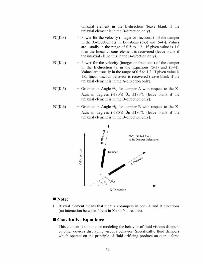
59
uniaxial element in the B-direction (leave blank if the uniaxial element is in the B-direction only).
PC(K,3) = Power for the velocity (integer or fractional) of the damper in the A-direction (α in Equations (5-3) and (5-4)). Values are usually in the range of 0.5 to 1.2. If given value is 1.0 then the linear viscous element is recovered (leave blank if the uniaxial element is in the B-direction only).
PC(K,4) = Power for the velocity (integer or fractional) of the damper in the B-direction (a in the Equations (5-3) and (5-4)). Values are usually in the range of 0.5 to 1.2. If given value is 1.0, linear viscous behavior is recovered (leave blank if the uniaxial element is in the A-direction only).
PC(K,5) = Orientation Angle θΑ for damper A with respect to the X-Axis in degrees (-180o≤ θΑ ≤180o). (leave blank if the uniaxial element is in the B-direction only).
PC(K,6) = Orientation Angle θΒ for damper B with respect to the X-Axis in degrees (-180o≤ θΒ ≤180o). (leave blank if the uniaxial element is in the B-direction only).
Note: 1. Biaxial element means that there are dampers in both A and B directions
(no interaction between forces in X and Y direction).
Constitutive Equations: This element is suitable for modeling the behavior of fluid viscous dampers or other devices displaying viscous behavior. Specifically, fluid dampers which operate on the principle of fluid orificing produce an output force

60
which is proportional to the power of the velocity (Constantinou et al., 1992).
The mobilized forces on a viscous element are described by
sgn( )A A A AF C U Uα
= (5-3)
sgn( )B B B BF C U Uα
= (5-4)
where AC , BC and AU , BU are damping coefficients and velocities experienced by viscous elements placed along the A and B directions respectively, and α is a coefficient taking real positive values. For 1α = , the linear viscous element is recovered.
C.7.3 Hysteretic Element for Elastomeric Bearings/Steel Yielding Devices
One card INELEM(K,3), INELEM(K, 1 ), INELEM(K,2)
INELEM(K,3) = Base below which isolator is located INELEM(K,1) = 1 or 2 or 3 INELEM(K,2) = 3 (Refer to C.7 for further details).
One card (ALP(K,I), I=1,2), (YF(K,I), I=1,2), (YD(K,I), I=1,2)
ALP(K,l) = Post-to-pre-yielding stiffness ratio (leave blank if the uniaxial element is in the Y-direction only);
YF(K,l) = Yield Force (leave blank if the uniaxial element is in the Y direction only);
YD(K,1) = Yield Displacement; in the X-direction for biaxial element or uniaxial element in the X-direction (leave blank if the uniaxial element is in the Y direction only);
ALP(K,2) = Post-to-pre-yielding stiffness ratio (leave blank if the uniaxia1 element is in the X-direction only);
YF(K,2) = Yield force (leave blank if the uniaxial element is in the X-direction only);
YD(K,2) = Yield displacement; in the Y-direction for biaxial element or uniaxial element in the Y-direction (leave blank if the uniaxial element is in the X-direction only).
Constitutive Equations:

61
This element may be used in modeling the behavior of low-damping rubber bearings, high-damping rubber bearings in the range of strain prior to stiffening, and lead-rubber bearings.
The forces along the orthogonal directions which are mobilized during motion of elastomeric bearings or steel yielding devices are described by
( )1Y
Yx x x
FF U F ZY
α α= + − (5-5)
( )1Y
Yy y y
FF U F ZY
α α= + − (5-6)
where α is the post-yielding to pre-yielding stiffness ratio; YF is the yield force; Y is the yield displacement; and xZ and yZ are dimensionless variables governed by the following system of differential equations which was proposed by Park et al. (1986) :
2
2
( sgn( ) ) ( sgn( ) )1 00 1 ( sgn( ) ) ( sgn( ) )
x x x x y y yx x x
y y yx y x x y y y
Z U Z Z Z U ZZ Y U UA
Z Y U UZ Z U Z Z U Z
γ β γ β
γ β γ β
⎡ ⎤+ +⎧ ⎫ ⎧ ⎫ ⎧ ⎫⎡ ⎤⎪ ⎪ ⎪ ⎪ ⎪ ⎪⎢ ⎥= −⎨ ⎬ ⎨ ⎬ ⎨ ⎬⎢ ⎥ ⎢ ⎥+ +⎣ ⎦⎪ ⎪ ⎪ ⎪ ⎪ ⎪⎩ ⎭ ⎩ ⎭ ⎩ ⎭⎣ ⎦ (5-7)
in which A , γ , and β are dimensionless quantities that control the shape of the hysteresis loop. Furthermore, xU , yU and xU , yU represent the displacements and velocities that occur at the isolation element.
C.7.4 Biaxial Hysteretic Element for Flat Sliding Bearings (Friction Coefficient Independent of Instantaneous Value of Normal Load)
One card INELEM(K,3), INELEM(K, 1 ), INELEM(K,2)
INELEM(K,3) = Base below which the isolator is located INELEM(K,1) = 1 or 2 or 3 INELEM(K,2) = 4 (Refer to C.7 for further details).
One card (FMAX(K,I), I=1,2), (FMIN(K,I), I=1,2), (PA(K,I), I=1,2), (YD(K,I), I=1,2), FN(K)
FMAX(K,1) = Maximum coefficient of sliding friction (leave blank if the uniaxial element is in the Y-direction only);
FMAX(K,2) = Maximum coefficient of sliding friction (leave blank if the uniaxial element is in the X-direction only);
FMIN(K,1) = Minimum coefficient of sliding friction (leave blank if the uniaxial element is in the Y-direction only);
FMIN(K,2) = Minimum coefficient of sliding friction (leave blank if the

62
uniaxial element is in the X-direction only);
PA(K,I) = Constant which controls the transition of coefficient of sliding friction from maximum to minimum value (leave blank if the uniaxial element is in the Y-direction only);
PA(K,2) = Constant which controls the transition of coefficient of sliding friction from maximum to minimum value (leave blank if the uniaxial element is in the X-direction only);
YD(K, 1) = Yield displacement; in the X-direction for biaxial element or uniaxial element in the X-direction (leave blank if the uniaxial element is in the Y-direction only);
YD(K,2) = Yield displacement; in the Y-direction for biaxial element or uniaxial element in the Y-direction (leave blank if the uniaxial element is in the X-direction only).
FN(K) = Initial normal force at the sliding interface.
Constitutive Equations: For flat sliding bearings, the mobilized forces are described by the equations (Constantinou et al., 1990; Mokha et al., 1993)
x s xF NZµ= (5-8)
y s yF NZµ= (5-9)
in which N is the vertical load carried by the bearing; and sµ is the coefficient of sliding friction which, in general, depends on the bearing pressure, direction of motion as specified by angle ( )1tan y xU Uθ −= and
the instantaneous velocity of sliding 2 2x yU U U= + .
The conditions of separation and reattachment and biaxial interaction are accounted for by variables xZ and yZ in Equation (5-7), namely
2
2
( sgn( ) ) ( sgn( ) )1 00 1 ( sgn( ) ) ( sgn( ) )
x x x x y y yx x x
y y yx y x x y y y
Z U Z Z Z U ZZ Y U UA
Z Y U UZ Z U Z Z U Z
γ β γ β
γ β γ β
⎡ ⎤+ +⎧ ⎫ ⎧ ⎫ ⎧ ⎫⎡ ⎤⎪ ⎪ ⎪ ⎪ ⎪ ⎪⎢ ⎥= −⎨ ⎬ ⎨ ⎬ ⎨ ⎬⎢ ⎥ ⎢ ⎥+ +⎣ ⎦⎪ ⎪ ⎪ ⎪ ⎪ ⎪⎩ ⎭ ⎩ ⎭ ⎩ ⎭⎣ ⎦
in which xU , yU and xU , yU represent the displacements and velocities respectively that occur at the isolation element; A , γ , and β are dimensionless quantities that control the shape of the hysteresis loop.
The dependency of the coefficient of friction on sliding velocity is explicitly modeled according to Equation (3-4), namely

63
max max min( ) a Us f f f eµ −= − −
where the coefficient of sliding friction sµ ranges from minf , at very low velocities of sliding, to maxf , at large velocities; U is the velocity of sliding; and α is a constant, having units of time per unit length, that controls the variation of the coefficient of friction with velocity. The dependency of the coefficient of friction on velocity is illustrated in Figure 3-2(a).
The dependency of the maximum coefficient of friction maxf on bearing pressure is neglected.
C.7.5 Biaxial Hysteretic Element for Flat Sliding Bearings (Friction Coefficient Dependent on Instantaneous Value of Normal Load) One card INELEM(K,3), INELEM(K,1), INELEM(K,2)
INELEM(K,3) = Base below which the isolator is located INELEM(K,1) = 1 or 2 or 3 INELEM(K,2) = 5 (Refer to C.7 for further details).
One card (FMAX(K,I), I=1,2), (FMIN(K,I), I=1,2), (PA(K,I), I=1,2), (YD(K,I), I=1,2), FN(K)
FMAX(K, 1 ) = Maximum coefficient of sliding friction at almost zero pressure ( max 0f in Equation (3-5)) (leave blank if the uniaxial element is in the Y-direction only);
FMAX(K,2) = Maximum coefficient of sliding friction at almost zero pressure ( max 0f in Equation (3-5)) (leave blank if the uniaxial element is in the X-direction only);
FMIN(K,l) = Minimum coefficient of sliding friction (independent of pressure) (leave blank if the uniaxial element is in the Y-direction only);
FMIN(K,2) = Minimum coefficient of sliding friction (independent of pressure) (leave blank if the uniaxial element is in the X-direction only);
PA(K,1) = Constant which controls the transition of coefficient of sliding friction from maximum ( maxf ) to minimum ( minf ) value (leave blank if the uniaxial element is in the Y-direction only);
PA(K,2) = Constant which controls the transition of coefficient of sliding friction from maximum ( maxf ) to minimum ( minf ) value (leave blank if the uniaxial element is in the X-

64
direction only);
YD(K,1) = Yield displacement; in the X-direction for biaxial element or uniaxial element in the X-direction (leave blank if the uniaxial element is in the Y-direction only).
YD(K,2) = Yield displacement; in the Y-direction for biaxial element or uniaxial element in the Y-direction (leave blank if the uniaxial element is in the X-direction only).
FN(K) = Initial normal force at the sliding interface (static condition).
Constitutive Equations: This element for flat sliding bearings is again described by Equations (5-7) to (5-9) with the exception that N is not constant but rather described by Equation (3-3), namely
1 gv OMu NN Wg W
⎛ ⎞= + +⎜ ⎟
⎝ ⎠
where W is the weight acting on the isolator; gvu is the vertical ground acceleration (positive when the direction is upwards); and OMN is the additional axial force due to overturning moment effects (positive when compressive).
The user needs to provide matrix [ ]T in file TMATRIX.DAT and matrix
[ ]A in file TMATRIXUPLF.DAT according to the procedure described in Section 3.4.
It should be noted that when gvu is not given and when the user-supplied routine returns zero for the additional axial load OMN , the model collapses to the constant normal load ( iN W= ) model.
The dependency of the maximum coefficient of friction maxf on bearing pressure is accounted for through Equation (3-5), namely
max max 0 max 0 max p( ) tanh( )f f f f pε= − −
where parameter maxf ranges from max 0f , at almost zero pressure, to max pf , at very high pressure; p is the bearing contact pressure; and ε is a constant that controls the variation of maxf between very low and very high pressures. Figure 3-2(b) presents the assumed variation of friction parameter maxf with pressure, which is typical of the behavior of sliding bearings.
65
The element requires the user-supplied subroutine FFMAX described in Section J.1.
C.7.6 Element for Friction Pendulum Bearing (FPS) (Friction Coefficient Dependent on Instantaneous Value of Normal Load)
One card INELEM(K,3), INELEM(K,1), INELEM(K,2)
INELEM(K,3) = Base below which the isolator is located INELEM(K,1) = 1 or 2 or 3 INELEM(K,2) = 6 (Refer to C.7 for further details).
One card ALP(K,3), (FMAX(K,I), I= 1,2), (FMIN(K,I), 1=1,2), (PA(K,I), I= 1,2), (YD(K,I), I= 1,2), FN(K)
ALP(K,3) = Radius of curvature of the concave surface of the bearing;
FMAX(K,1) = Maximum coefficient of sliding friction at almost zero pressure ( max 0f in Equation (3-5)) (leave blank if the uniaxial element is in the Y-direction only);
FMAX(K,2) = Maximum coefficient of sliding friction at almost zero pressure ( max 0f in Equation (3-5)) (leave blank if the uniaxial element is in the X-direction only);
FMIN(K,1) = Minimum coefficient of sliding friction (independent of pressure) (leave blank if the uniaxial element is in the Y-direction only);
FMIN(K,2) = Minimum coefficient of sliding friction (independent of pressure) (leave blank if the uniaxial element is in the X-direction only);
PA(K,1) = Constant which controls the transition of coefficient of sliding friction from maximum ( maxf ) to minimum ( minf ) value (leave blank if the uniaxial element is in the Y-direction only);
PA(K,2) = Constant which controls the transition of coefficient of sliding friction from maximum ( maxf ) to minimum ( minf ) value (leave blank if the uniaxial element is in the X-direction only);
YD(K,1) = Yield displacement; in the X-direction for biaxial element or uniaxial element in the X-direction (leave blank if the uniaxial element is in the Y-direction only);
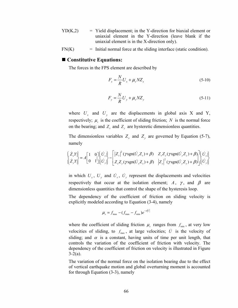
66
YD(K,2) = Yield displacement; in the Y-direction for biaxial element or uniaxial element in the Y-direction (leave blank if the uniaxial element is in the X-direction only).
FN(K) = Initial normal force at the sliding interface (static condition).
Constitutive Equations: The forces in the FPS element are described by
x x s xNF U NZR
µ= + (5-10)
y y s yNF U NZR
µ= + (5-11)
where xU and yU are the displacements in global axis X and Y, respectively; sµ is the coefficient of sliding friction; N is the normal force on the bearing; and xZ and yZ are hysteretic dimensionless quantities.
The dimensionless variables xZ and yZ are governed by Equation (5-7), namely
2
2
( sgn( ) ) ( sgn( ) )1 00 1 ( sgn( ) ) ( sgn( ) )
x x x x y y yx x x
y y yx y x x y y y
Z U Z Z Z U ZZ Y U UA
Z Y U UZ Z U Z Z U Z
γ β γ β
γ β γ β
⎡ ⎤+ +⎧ ⎫ ⎧ ⎫ ⎧ ⎫⎡ ⎤⎪ ⎪ ⎪ ⎪ ⎪ ⎪⎢ ⎥= −⎨ ⎬ ⎨ ⎬ ⎨ ⎬⎢ ⎥ ⎢ ⎥+ +⎣ ⎦⎪ ⎪ ⎪ ⎪ ⎪ ⎪⎩ ⎭ ⎩ ⎭ ⎩ ⎭⎣ ⎦
in which xU , yU and xU , yU represent the displacements and velocities respectively that occur at the isolation element; A , γ , and β are dimensionless quantities that control the shape of the hysteresis loop.
The dependency of the coefficient of friction on sliding velocity is explicitly modeled according to Equation (3-4), namely
max max min( ) a Us f f f eµ −= − −
where the coefficient of sliding friction sµ ranges from minf , at very low velocities of sliding, to maxf , at large velocities; U is the velocity of sliding; and α is a constant, having units of time per unit length, that controls the variation of the coefficient of friction with velocity. The dependency of the coefficient of friction on velocity is illustrated in Figure 3-2(a).
The variation of the normal force on the isolation bearing due to the effect of vertical earthquake motion and global overturning moment is accounted for through Equation (3-3), namely

67
1 gv OMu NN Wg W
⎛ ⎞= + +⎜ ⎟
⎝ ⎠
where W is the weight acting on the isolator; gvu is the vertical ground acceleration (positive when the direction is upwards); and OMN is the additional axial force due to overturning moment effects (positive when compressive).
The user needs to provide matrix [ ]T in file TMATRIX.DAT and matrix
[ ]A in file TMATRIXUPLF.DAT according to the procedure described in Section 3.4.
It should be noted that when gvu is not given and when the user-supplied routine returns zero for the additional axial load OMN , the model collapses to the constant normal load ( iN W= ) model.
The dependency of the maximum coefficient of friction maxf on bearing pressure is accounted for through Equation (3-5), namely
max max 0 max 0 max p( ) tanh( )f f f f pε= − −
where parameter maxf ranges from max 0f , at almost zero pressure, to max pf , at very high pressure; p is the bearing contact pressure; and ε is a constant that controls the variation of maxf between very low and very high pressures. Figure 3-2(b) presents the assumed variation of friction parameter maxf with pressure, which is typical of the behavior of sliding bearings.
The element requires the user-supplied subroutine FFMAX described in Section J.1.
C.7.7 Stiffening Biaxial Hysteretic Element for Elastomeric Bearings One card INELEM(K,3), INELEM(K,1), INELEM(K,2)
INELEM(K,3) = Base below which the isolator is located INELEM(K,1) = 1 or 2 or 3 INELEM(K,2) = 7 (Refer to C.7 for further details).
One card ALP(K,3), ALP(K,4), ALP(K,5), ALP(K,6), ALP(K,7), YD(K,1)
ALP(K,3) = Characteristic strength (Q of Equation 4.6); ALP(K,4) = Tangent stiffness K1 (see Equation 4.1); ALP(K,5) = Tangent stiffness K2 (see Equation 4.1);

68
ALP(K,6) = Displacement limit D1 (see Equation 4.1); ALP(K,7) = Displacement limit D2 (see Equation 4.1); YD(K,1) = Yield displacement;
Constitutive Equations: The element is appropriate for modeling the behavior of high-damping rubber bearings. Typically, these bearings exhibit higher stiffness at large strains. The element is formed by combining the elastoplastic version ( 0α = ) of the biaxial hysteretic element described by Equations (5-5) through (5-7) and a stiffening bilinear spring.
The complete model consists of the combination of components given by Equations (5-5) and (5-6), with 0α = and YF Q= , and components xsF and ysF of the resultant force F of the stiffening bilinear spring:
x x xsF QZ F= + (5-12)
y y ysF QZ F= + (5-13)
where
cosxsF F θ= (5-14)
sinysF F θ= (5-15)
in which
1 12
2 1 11 1 2
2 1
1 2 1 22 2
,( ) ( ) sgn( ) ,( ) 2( )( ) sgn( ) ,
2
K U U DK K U DF U K U D U DD DK K D D U K U U D
⎧ ⎫⎪ ⎪≤⎪ ⎪
− −⎪ ⎪= + < ≤⎨ ⎬−⎪ ⎪⎪ ⎪− + + >⎪ ⎪⎩ ⎭
(5-16)

69
*
*
*
*
when , 0/ 2 when 0, 0
when , 0
when 0, 0/ 2 and when 00 and when 0
x y
x y
x y
x y
y x
x y
U UU U
U UU U
U U UU U U
θ θθ θ π
θ θ πθ θ
θ πθ
⎫= >⎪= + < > ⎪⎪= + < ⎪⎬= − > < ⎪⎪= = =⎪
= = = ⎪⎭
(5-17)
and
* 1tan y
x
UU
θ −⎛ ⎞⎜ ⎟=⎜ ⎟⎝ ⎠
(5-18)
In Equation (5-16), 2 2x yU U U= + is the resultant displacement; 1K is
the tangent stiffness mobilized for displacements less than the limit 1D ; and 2K is the higher tangent stiffness mobilized for displacements larger than the limit 2D , as illustrated in the figure below.

70
Model for stiffening bilinear spring.
C.7.8 Element for Uplift-Restraining (XY-FP) Friction Pendulum Bearing One card INELEM(K,3), INELEM(K,1), INELEM(K,2)
INELEM(K,3) = Base below which the isolator is located INELEM(K,1) = 1 or 2 or 3 INELEM(K,2) = 8 (Refer to C.7 for further details).
Three Cards ALP(K,3), ALP(K,5), FN(K), ALP(K,4) Compression: (FMAX(K,J), J=1,2), (FMIN(K,J), J=1,2), (PA(K,J), J=1,2), (YD(K,J), J=1,2) Tension: (FMAX(K,J), J=3,4), (FMIN(K,J), J=3,4), (PA(K,J), J=3,4), (YD(K,J), J=3,4)
ALP(K,3) = R1 ; Radius of curvature of the concave surface of the bearing in direction 1;
ALP(K,5) = R2 ; Radius of curvature of the concave surface of the bearing in direction 1;
FN(K) = Initial normal force at the sliding interface (static condition) ALP(K,4) = Angle of orientation of the isolator with respect to global X-
direction in units of degrees.
Frictional Interface Properties when Isolator in COMPRESSION FMAX(K,1) = Maximum coefficient of sliding friction at almost zero
pressure in 1-direction ( max 0f in Equation (3-5))
FMAX(K,2) = Maximum coefficient of sliding friction at almost zero pressure in 2-direction ( max 0f in Equation (3-5))
FMIN(K,1) = Minimum coefficient of sliding friction (independent of

71
pressure) in 1-direction
FMIN(K,2) = Minimum coefficient of sliding friction (independent of pressure) in 2-direction
PA(K,1) = Constant which controls the transition of coefficient of sliding friction from maximum ( maxf ) to minimum ( minf ) value along 1-direction.
PA(K,2) = Constant which controls the transition of coefficient of sliding friction from maximum ( maxf ) to minimum ( minf ) value along 2-direction.
YD(K,1) = Yield displacement in the 1-direction
YD(K,2) = Yield displacement in the 2-direction
Frictional Interface Properties when Isolator in TENSION FMAX(K,3) = Maximum coefficient of sliding friction at almost zero
pressure in 1-direction ( max 0f in Equation (3-5))
FMAX(K,4) = Maximum coefficient of sliding friction at almost zero pressure in 2-direction ( max 0f in Equation (3-5))
FMIN(K,3) = Minimum coefficient of sliding friction (independent of pressure) in 1-direction
FMIN(K,4) = Minimum coefficient of sliding friction (independent of pressure) in 2-direction
PA(K,3) = Constant which controls the transition of coefficient of sliding friction from maximum ( maxf ) to minimum ( minf ) value along 1-direction.
PA(K,4) = Constant which controls the transition of coefficient of sliding friction from maximum ( maxf ) to minimum ( minf ) value along 2-direction.
YD(K,3) = Yield displacement in the 1-direction
YD(K,4) = Yield displacement in the 2-direction
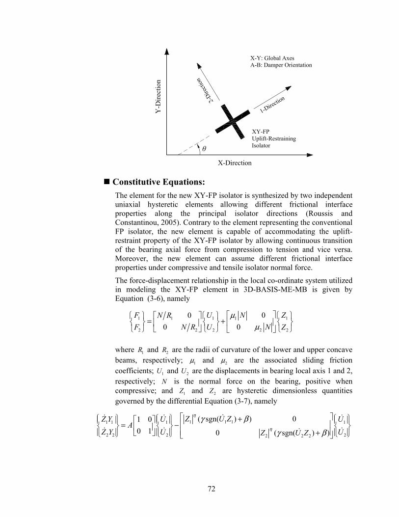
72
Constitutive Equations: The element for the new XY-FP isolator is synthesized by two independent uniaxial hysteretic elements allowing different frictional interface properties along the principal isolator directions (Roussis and Constantinou, 2005). Contrary to the element representing the conventional FP isolator, the new element is capable of accommodating the uplift-restraint property of the XY-FP isolator by allowing continuous transition of the bearing axial force from compression to tension and vice versa. Moreover, the new element can assume different frictional interface properties under compressive and tensile isolator normal force.
The force-displacement relationship in the local co-ordinate system utilized in modeling the XY-FP element in 3D-BASIS-ME-MB is given by Equation (3-6), namely
1 1 111
222 2 2
0000
F U ZNN RNN RF U Z
µµ
⎡ ⎤⎧ ⎫ ⎧ ⎫ ⎧ ⎫⎡ ⎤= +⎨ ⎬ ⎨ ⎬ ⎨ ⎬⎢ ⎥⎢ ⎥⎣ ⎦⎩ ⎭ ⎩ ⎭ ⎩ ⎭⎣ ⎦
where 1R and 2R are the radii of curvature of the lower and upper concave beams, respectively; 1µ and 2µ are the associated sliding friction coefficients; 1U and 2U are the displacements in bearing local axis 1 and 2, respectively; N is the normal force on the bearing, positive when compressive; and 1Z and 2Z are hysteretic dimensionless quantities governed by the differential Equation (3-7), namely
1 1 11 1 1 1
2 2 2 22 2 2
( sgn( ) ) 01 00 1 0 ( sgn( ) )
Z U ZZ Y U UA
Z Y U UZ U Z
η
η
γ β
γ β
⎡ ⎤⎧ ⎫ ⎧ ⎫ ⎧ ⎫+⎡ ⎤⎪ ⎪ ⎪ ⎪ ⎪ ⎪⎢ ⎥= −⎨ ⎬ ⎨ ⎬ ⎨ ⎬⎢ ⎥⎢ ⎥+⎪ ⎪ ⎣ ⎦ ⎪ ⎪ ⎪ ⎪⎩ ⎭ ⎩ ⎭ ⎩ ⎭⎣ ⎦

73
where 1U and 2U are the velocities in local axis 1 and 2, respectively; A , β , γ and η are dimensionless quantities that control the shape of the hysteresis loop; and 1Y and 2Y represent the yield displacements.
The corresponding force-displacement relationship in the global co-ordinate system is given by Equation (3-2):
1
2
cos sinsin cos
Tx
y
F FF F
θ θθ θ
⎧ ⎫ ⎧ ⎫⎡ ⎤=⎨ ⎬ ⎨ ⎬⎢ ⎥−⎣ ⎦ ⎩ ⎭⎩ ⎭
The dependency of the coefficient of friction on sliding velocity is explicitly modeled according to Equation (3-4), namely
max max min( ) a Us f f f eµ −= − −
where the coefficient of sliding friction sµ ranges from minf , at very low velocities of sliding, to maxf , at large velocities; U is the velocity of sliding; and α is a constant, having units of time per unit length, that controls the variation of the coefficient of friction with velocity. The dependency of the coefficient of friction on velocity is illustrated in Figure 3-2(a).
The variation of the normal force on the isolation bearing due to the effect of vertical earthquake motion and global overturning moment is accounted for through Equation (3-3), namely
1 gv OMu NN Wg W
⎛ ⎞= + +⎜ ⎟
⎝ ⎠
where W is the weight acting on the isolator; gvu is the vertical ground acceleration (positive when the direction is upwards); and OMN is the additional axial force due to overturning moment effects (positive when compressive).
The user needs to provide matrix [ ]T in file TMATRIX.DAT according to the procedure described in Section 3.4.1.
The dependency of the maximum coefficient of friction maxf on bearing pressure is accounted for through Equation (3-5), namely
max max 0 max 0 max p( ) tanh( )f f f f pε= − −
where parameter maxf ranges from max 0f , at almost zero pressure, to max pf , at very high pressure; p is the bearing contact pressure; and ε is a constant that controls the variation of maxf between very low and very high

74
pressures. Figure 3-2(b) presents the assumed variation of friction parameter maxf with pressure, which is typical of the behavior of sliding bearings.
The element requires the user-supplied subroutine FFMAX described in Section J.1.
C.7.9 General Nonlinear Viscous Element One card INELEM(K,3), INELEM(K,1), INELEM(K,2)
INELEM(K,3) = Base below which the isolator is located INELEM(K,1) = 1 or 2 or 3 INELEM(K,2) = 9 (Refer to C.7 for further details).
One card (PC(K,I), I=1,14)
PC(K,1) = Force offset for dampers A or B in range 1 (F01 in Equation (5-19)). (leave blank if the uniaxial element is in the B-direction only).
PC(K,2) = Force offset for dampers A or B in range 2 (F02 in Equation (5-19)). (leave blank if the uniaxial element is in the A-direction only).
PC(K,3) = Nonlinear viscous constant for damper A in range 1 (C1A in Equation (5-19)) (leave blank if the uniaxial element is in the B-direction only).
PC(K,4) = Nonlinear viscous constant for damper A in range 2 (C2A in Equation (5-19)) (leave blank if the uniaxial element is in the B-direction only).
PC(K,5) = Limit velocity for transition from range 1 to 2 in A-direction ( )12 AV (leave blank if the uniaxial element is in the B-
direction only).
PC(K,6) = Nonlinear viscous constant for damper B in range 1 (C1B in Equation (5-19)) (leave blank if the uniaxial element is in the A-direction only).
PC(K,7) = Nonlinear viscous constant for damper B in range 2 (C2B in Equation (5-19)) (leave blank if the uniaxial element is in the A-direction only).
PC(K,8) = Limit velocity for transition from range 1 to 2 in B-direction ( )12 BV (leave blank if the uniaxial element is in the A-
direction only).
PC(K,9) = Power for the velocity (integer or fractional) in the range 1
75
for either dampers A or B (p1 in Equation (5-19))
PC(K,10) = Power for the velocity (integer or fractional) in the range 2 for either dampers A or B (p2 in Equation (5-19))
PC(K,11) = Maximum damper force for either one of the dampers A or B ( maxF in Equation (5-19))
PC(K,12) = Displacement limit for damper operation start at low velocities and displacements for either A or B.
PC(K,13) = Orientation Angle θΑ for damper A with respect to the X-Axis in degrees (-180o≤ θΑ ≤180o ). (leave blank if the uniaxial element is in the B-direction only).
PC(K,14) = Orientation Angle θΒ for damper B with respect to the X-Axis in degrees (-180o≤ θΒ ≤180o ) (leave blank if the uniaxial element is in the B-direction only).
Note: 1. This model is suitable for a cluster of two (horizontal) damper A and B
oriented at an arbitrary angle to each other and to the building. The dampers have different nonlinear properties, but same maximum and same offset constants. Biaxial element means that there are dampers in both A and B directions (no interaction between forces in X and Y direction).
Constitutive Equations: The force-velocity relation of the general nonlinear viscous element is given by

76
( )( )
1
2
01 1 12
02 2 max 12
sgn( ) if
sgn( ) if
p
D p
F C U U U VF
F C U U F U V
⎧ + ≤⎪= ⎨⎪ + ≤ >⎩
(5-19)

77
D.1 OUTPUT DATA
D.2 OUTPUT PARAMETERS USER_TXT Reference information; up to 80 characters of text. One card LTMH, KPD, IPROF
LTMH: LTMH = 1 for both the time history and peak response output. LTMH = 0 for only peak response output.
KPD = No. of time steps before the next response quantity is output.
IPROF: IPROF = 1 for accelerations-displacements profiles output. IPROF = 0 for no accelerations-displacements profiles output.
D.3 ISOLATOR OUTPUT USER_TXT Reference information; up to 80 characters of text. INP cards IP(I), I=1,INP
IP(I) = Bearing number of bearings I at which the force and displacement response is desired.
Note: 1. If INP equals zero then skip Section D.3.
D.4 INTERSTORY DRIFT OUTPUT The following set of cards must be imported as many times as the number of super-structures NB.
USER_TXT Reference information; up to 80 characters of text. One card ICOR(I), I=l,NB
ICOR(I) = Number of column lines of superstructure I at which the interstory drift is desired.
ICOR(I) cards CORDX(K), CORDY(K), K= 1,ICOR(I)
CORDX(K) = X co-ordinate of the column line at which the interstory drift
is desired.

78
CORDY(K) = Y co-ordinate of the column line at which the interstory drift is desired.
Note: 1. Maximum number of columns at which drift output may be requested is
limited to six for each superstructure (maximum value for ICOR(I) is six)
2. The coordinates of the column lines are with respect to the reference axis at the center of mass of the top (first) base.
E.1 INITIAL CONDITIONS USER_TXT Reference information; up to 80 characters of text. NBSLBS cards DN(3*(K-1)+1,1), DN(3*(K-1)+2,1), DN(3*(K-1)+3,1), K=1,NBSLBS
DN(3*(K-1)+1,1) = Initial displacement of the C.M. of base K along the X-direction
DN(3*(K-1)+2,1) = Initial displacement of the C.M. of base K along the Y-direction
DN(3*(K-1)+3,1) = Initial rotation of the C.M. of base K.
F.1 SEISMIC INPUT (EARTHQUAKE TIME HISTORIES) This set of data requires separate file(s) from the set of data presented in sections A to E.
F.2 UNI-DIRECTIONAL EARTHQUAKE RECORD File: WAVEX.DAT
USER_TXT Reference information; up to 80 characters of text. LOR cards X(I), I= 1,LOR
X(I) = Unidirectional acceleration component.
Note: 1. If INDGACC as specified in A.4.4 is 1 or 3, then the input will be assumed
at an angle XTH specified in A.4.4. If INDGACC as specified in A.4.4 is 2 or 4, then X(LOR) is considered to be the X component of the bidirectional earthquake.

79
F.3 EARTHQUAKE RECORD IN THE Y-DIRECTION FOR BIDIRECTIONAL EARTHQUAKE File: WAVEY.DAT (Input only if INDGACC = 2 or 4)
USER_TXT Reference information; up to 80 characters of text. LOR cards Y(I,l), I=1,LOR
Y(I,1) = Acceleration component in the Y direction.
F.4 EARTHQUAKE RECORD IN THE Z (VERTICAL) DIRECTION File: WAVEZ.DA T (Input only if INDGACC = 3 or 4)
USER_TXT Reference information; up to 80 characters of text. LOR cards Y(I,2), I=1,LOR
Y(I,2) = Acceleration component in the Z direction.
G.1 NORMAL LOAD VARIATION INPUT FOR ISOLATORS This set of data requires separate files from the set of data presented in sections A to F.
This set of data is supplied only for ITMAT =2 (in section A.4.1)
G.2 EFFECT OF INERTIAL LOADS (HORIZONTAL LOADS ON FLOORS AND BASES) ON THE NORMAL LOADS OF ISOLATORS File: TMATRIX.DAT (Input only if ITMAT = 2)
USER_TXT Reference information; up to 80 characters of text. NP cards TMATRIX(I,J), J = 1, 3*MNF+3*NBSLBS
TMATRIX(I,J) = Coefficients relating the normal loads on the isolators with the horizontal inertia forces.
G.3 EFFECT OF ISOLATOR UPLIFT ON THE NORMAL LOADS OF THE ISOLATORS File: TMATRIXUPLF.DAT (Input only if ITMAT = 2)
USER_TXT Reference information; up to 80 characters of text.

80
NP cards ALPHA(I,J), J = 1,NP
ALPHA(I,J) = Coefficients relating axial loads on the isolators when one isolator undergoes uplift.

81
H.1 OUTPUT FILES The set of output files and their contents are presented in the table below.
FILE DESCRIPTION / COMMENT 3DBMEMB.OUT General output, summary results in terms of Maxima and Minima
and profiles of accelerations and displacements 1001, 1002, etc. Time histories of Superstructure quantities (Accelerations and
Displacements) BASE Time histories of quantities related to bases (Isolator Displacement
and Forces, Structural Shears and Base Shears) ISOLBASE_No 1.OUT, ISOLBASE_No2.OUT, etc.
Time histories of Accelerations and Displacements at C.M. of each Base
ISOL8 Time histories of all Isolators of Type 8 only The following files are printed to aid the user in plotting important results ACCELR.INP Accelerations for all dynamic DOF of the model at C.M. of each
level 1st col.: Time, 2nd col: Accel. in x-dir. of top floor of superstructure #1 3nd col: Accel. in y-dir. of top floor of superstructure #1 4th col: Accel. in rot-dir. of top floor of superstructure #1 5th col: Accel. in x-dir. of the second-from-the-top floor of
superstructure #1 …..the dynamic DOFs of superstructure #2 follow ….. …..the dynamic DOFs of the isol. bases follow from top to bottom
DISPLR.INP Displacements for all dynamic DOF of the model at C.M. of each level 1st col.: Time, 2nd col: Displ. in x-dir. of top floor of superstructure #1 3nd col: Displ. in y-dir. of top floor of superstructure #1 4th col: Displ. in rot-dir. of top floor of superstructure #1 5th col: Displ. in x-dir. of the second-from-the-top floor of
superstructure #1 …..the Dynamic DOFs of superstructure #2 follow ….. …..the Dynamic DOFs of the isol. bases follow, from top to bottom
ISOL_NOR-FORCE.INP Normal forces on isolators Output for (n) number of isolators requested in Section D3
ISOL_D-F_X-DIR.INP, ISOL_D-F_X-DIR.INP
Isolator Displacement and Forces in X-dir and Y-dir respectively Output for (n) number of isolators requested in Section D3 1st col.: Time, 2nd col: Displ. of Isolator #1 3nd col: Displ. of Isolator #2 ….. nth +1 col: Force of Isolator #1 ….
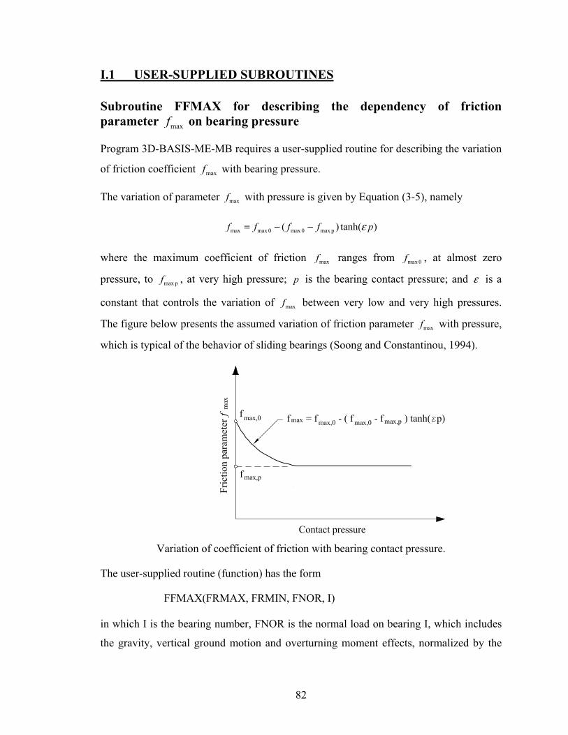
82
I.1 USER-SUPPLIED SUBROUTINES
Subroutine FFMAX for describing the dependency of friction parameter maxf on bearing pressure
Program 3D-BASIS-ME-MB requires a user-supplied routine for describing the variation
of friction coefficient maxf with bearing pressure.
The variation of parameter maxf with pressure is given by Equation (3-5), namely
max max 0 max 0 max p( ) tanh( )f f f f pε= − −
where the maximum coefficient of friction maxf ranges from max 0f , at almost zero
pressure, to max pf , at very high pressure; p is the bearing contact pressure; and ε is a
constant that controls the variation of maxf between very low and very high pressures.
The figure below presents the assumed variation of friction parameter maxf with pressure,
which is typical of the behavior of sliding bearings (Soong and Constantinou, 1994).
Variation of coefficient of friction with bearing contact pressure.
The user-supplied routine (function) has the form
FFMAX(FRMAX, FRMIN, FNOR, I)
in which I is the bearing number, FNOR is the normal load on bearing I, which includes
the gravity, vertical ground motion and overturning moment effects, normalized by the
83
weight iW on the bearing. Furthermore, FRMAX and FRMIN are respectively the
parameters max 0f and min 0f under almost zero static pressure of bearing I, supplied
through the input file. Function FFMAX returns the value of maxf at the bearing pressure
resulting from the instantaneous normal load. Note that parameter minf is assumed
independent of pressure, that is min 0 minf f= .
As an example, Constantinou et al. (1993) gave the following values for the parameters
of a bearing at pressure of 17.2 MPa: max 0 0.12f = , max p 0.05f = , 0.012ε = ( p is in units
of MPa). For this case function FFMAX should be of the form:
FUNCTION FFMAX(FRMAX, FRMIN, FNOR, I) IMPLICIT REAL *8 COMMON / MAIN1 / NB, NP, MNF, MNE, NFE, MXF DIMENSIQN P(500) DATA / P(J)=17.2, J=1,../ etc. PRES=FNOR*P(I) FFMAX=FRMAX-0.07*DTANH(0.012*PRES) RETURN END
Note that P(J) contains the bearing pressure under static conditions of bearing J. Quantity
PRES is the instantaneous bearing pressure in units of MN/m2 or MPa.
In the case where the dependency on pressure of parameter maxf is neglected⎯as is the
default in 3DBASIS-ME-MB⎯function FFMAX should be
FUNCTION FFMAX(FRMAX, FRMIN, FNOR, I) IMPLICIT REAL *8 COMMON / MAIN1 / NB, NP, MNF, MNE, NFE, MXF FFMAX=FRMAX RETURN END


85
SECTION 6
SUMMARY
Program 3D-BASIS-ME-MB represents a versatile tool for the analysis of complex
seismically-isolated structures. The new program offers improvements over its
predecessor (3D-BASIS-ME) including the capability to analyze multiple superstructures
on multiple isolation-system levels; the addition of a new element for modeling the
mechanical behavior of the uplift-restraining XY-FP isolator; an improvement of the
existing viscous damper element; capability to capture the effects of lateral loads on
bearing axial forces, including bearing uplift; and streamlined program output.
Two examples of seismically isolated structures have been used for verifying 3D-BASIS-
ME-MB and demonstrating its capabilities. The first example is a 7-story model structure
that was tested on the earthquake simulator of the University at Buffalo (Al-Hussaini et
al, 1994) and was also used as a verification example for program SAP2000 (Scheller and
Constantinou, 1999 and Computers and Structures, 2004). The second example is a two-
tower, multi-story structure with a split seismic-isolation-system level. In both examples
the analyzed structure is seismically isolated with Friction Pendulum bearings and is
excited under conditions of bearing uplift. This represents the most extreme condition
that bearings are subjected to and is a case of much interest in verifying the capabilities of
analysis software.
In the first example, analysis results obtained from program 3D-BASIS-ME-MB are
compared with both experimental results and results obtained from program ABAQUS.
In the second example, results of analysis produced by program 3D-BASIS-ME-MB are
compared with results obtained from program ABAQUS.
The satisfactory comparisons of results in both examples attest to the validity and
accuracy of program 3D-BASIS-ME-MB.

86
Finally, it should be noted that program 3D-BASIS-ME-MB has inherent limitations as
described below:
1) Although it is possible to detect bearing uplift from histories of isolator
axial load (also from the shapes of isolator force-displacement loops and
from histories of isolator shear force), the program cannot calculate the
isolator uplift displacement.
2) Analysis of structures with split level isolation system is approximate in
the sense that the effect on the isolator axial loads of the shear force
distribution at the various isolation levels is approximate.
3) The program is not capable of capturing rigid body rocking effects that
result from isolator uplift. (To capture these effects, geometrically
nonlinear analysis would be required).

87
SECTION 7
REFERENCES
ABAQUS, Inc. (2004), “ABAQUS Analysis User’s Manual,” Version 6.4, Pawtucket,
Rhode Island.
Al-Hussaini T. M., Zayas V. A., and Constantinou M. C. (1994), “Seismic Isolation of
Multi-Story Frame Structures Using Spherical Sliding Isolation System,” Technical
Report NCEER-94-0007, National Center for Earthquake Engineering Research, State
University of New York, Buffalo, NY.
Clarke, C. S. J., Buchanan, R., Efthymiou, M., and Shaw, C. (2005), “Structural Platform
Solution for Seismic Arctic Environments⎯Sakhalin II Offshore Facilities,” Paper OTC-
17378-PP, Offshore Technology Conference, Houston, Texas.
Computers and Structures, Inc. (1998), “SAP2000 Analysis Reference Manual,” Version
7.5, Berkeley, CA.
Computers and Structures Inc. (2003), “SAP2000: Integrated Finite Element Analysis
and Design of Structures,” Version 8.2, Berkeley, CA.
Computers and Structures Inc. (1995), “ETABS Analysis Reference Manual,” Version
6.0, Berkeley, CA.
Constantinou M. C., Mokha A., and Reinhorn A. M. (1990), “Teflon Bearings in Base
Isolation II: Modeling,” Journal of Structural Engineering; 116(2): 455-474.
Constantinou, M. C. and Symans, M. D. (1992), “Experimental and analytical
investigation of seismic response of structures with supplemental fluid viscous dampers,”
Technical Report NCEER-92-0032, National Center for Earthquake Engineering
Research, State University of New York, Buffalo, NY.
Mokha A., Constantinou M. C., and Reinhorn A. M. (1988), “Teflon Bearings in
Aseismic Base Isolation: Experimental Studies and Mathematical Modeling,” Technical
Report NCEER-88-0038, National Center for Earthquake Engineering Research, State
88
University of New York, Buffalo, NY.
Mokha, A. S., Constantinou, M. C., and Reinhorn, A. M. (1993), “Verification of Friction
Model of Teflon Bearings under Triaxial Load,” Journal of Structural Engineering,
119(1), 240-261.
Nagarajaiah, S., Reinhorn, A.M., and Constantinou, M.C. (1989), “Nonlinear Dynamic
Analysis of Three Dimensional Base Isolated Structures (3D-BASIS),” Technical Report
NCEER-89-0019, National Center for Earthquake Engineering Research, State University
of New York, Buffalo, NY.
Nagarajaiah, S. (1990), “Nonlinear Dynamic Analysis of Three Dimensional Base
Isolated Structures”, Ph.D. Thesis, University at Buffalo, State University of New York,
Buffalo, NY.
Nagarajaiah, S., Reinhorn, A.M., and Constantinou, M.C. (1991a), “Nonlinear Dynamic
Analysis of Three Dimensional Base Isolated Structures”, Journal of Structural
Engineering, ASCE, Vol. 117, No. 7, 2035-2054.
Nagarajaiah, S., Reinhorn, A.M., and Constantinou, M.C. (1991b), “3D-BASIS:
Nonlinear Dynamic Analysis of Three Dimensional Base Isolated Structures,” Technical
Report NCEER-91-0005, National Center for Earthquake Engineering Research, State
University of New York, Buffalo, NY.
Ozdemir H. (1976), “Nonlinear Transient Dynamic Analysis of Yielding Structures,”
Ph.D. Thesis, Department of Civil Engineering, University of California, at Berkeley,
CA.
Park, Y. J., Wen, Y. K., and Ang, A. H. S. (1986), “Random Vibration of Hysteretic
Systems under Bidirectional Ground Motions,” Earthquake Engineering and Structural
Dynamics, 14(4), 543-557.
Research Engineers International (2002), “Computer Program STAAD Pro.”
Roussis, P. C. and Constantinou, M. C. (2005), “Experimental and Analytical Studies of

89
Structures Seismically Isolated with an Uplift-Restraint Isolation System,” Technical
Report MCEER-05-0001, Multidisciplinary Center for Earthquake Engineering
Research, State University of New York, Buffalo, NY.
Scheller, J. and Constantinou, M. C. (1999), “Response History Analysis of Structures
with Seismic Isolation and Energy Dissipation Systems: Verification Examples for
Program SAP2000,” Technical Report MCEER-99-0002, Multidisciplinary Center for
Earthquake Engineering Research, Buffalo, NY.
Soong T. T. and Constantinou M. C. (1994), Passive and Active Structural Vibration
Control in Civil Engineering, Springer-Verlag: Wien, NY.
Tsopelas, P.C., Constantinou, M.C., and Reinhorn, A.M. (1994), “3D-BASIS-ME:
Computer Program for Nonlinear Dynamic Analysis of Seismically Isolated Single and
Multiple Structures and Liquid Storage Tanks,” Technical Report MCEER-94-0010,
Multidisciplinary Center for Earthquake Engineering Research, State University of New
York, Buffalo, NY.
Zayas V., Low S. S., and Mahin S. A. (1987), “The FPS Earthquake Resisting System:
Experimental Report,” Technical Report UBC/EERC-87/01, Earthquake Engineering
Research Center, University of California, Berkeley, CA.


91
APPENDIX A
EXAMPLE OF CALCULATION OF STORY STIFFNESS
AND LOCATION OF CENTER OF STIFFNESS
92
EXAMPLE OF CALCULATION OF STORY STIFFNESS
AND LOCATION OF CENTER OF STIFFNESS
This appendix presents an example of calculating the stiffness and location of the center of
stiffness of a story. A story is the part of the substructure between two bases exclusive of the
isolators. The resultant stiffness in the two horizontal directions, the rotational stiffness and the
location of the center of stiffness are parameters that must be input in program 3D-BASIS-ME-
MB for each story of the substructure.
Consider Figure 1-2 and the story between bases 3 and 4. In determining the stiffness and
location of the center of stiffness of this story, the structure needs to be modeled in a static
analysis program exclusive of the isolators. Each base in this model will be modeled as a rigid
diaphragm. Base 4 will be restrained against lateral movement and rotation. Horizontal loads will
be applied to base 3 and the displacement and rotation of base 3 with respect to base 4 will be
calculated and used to determine the stiffness and location of the center of stiffness. Two loading
cases in each principal direction need to be considered. It is appropriate to include in the model
of analysis the part of the structure above base 3. However, in the example this part is
disregarded for simplicity and ease in the presentation of results.
Figure A-1 shows the analyzed system. Since base 4 is the lowest base (at the ground level) it
modeled fixed to the ground. Also, the part above base 3 is disregarded (only for simplicity in
this example). The vertical elements in this story consist of six columns of which four are rigidly
connected to the bases and two (numbered 1 and 2) are pin-connected at the bottom. Figure A-1
presents the model of the story in program STAAD. Input to this program is listed in Table A-1.
Analysis is performed only for loading in the transverse direction (direction Z in the STAAD
model) so that only the following can be calculated: rotational stiffness, transverse stiffness (or Z
direction stiffness in the STAAD model) and the location of the center of stiffness in the
longitudinal direction (direction X in the STAAD model). A similar analysis for loading in the
longitudinal direction (or X direction in the STAAD model) will result in the longitudinal
stiffness (or X direction stiffness in the STAAD model) and the location of the center of stiffness
along the transverse direction (or Z direction in the STAAD model).
Loads are applied at joints 7 and 18 in the transverse direction and the displacements and
rotations are calculated. Output of program STAAD is listed in Table A-2 and Figure A-2 shows

93
a graph of the deformed structure under action of one of the joint loads.
Figure A-1: Model of story between bases 3 and 4 in program STAAD.
Table A-1: Input to program STAAD
STAAD SPACE * EXAMPLE PROBLEM FOR CALCULATING *STIFFNESS AND LOCATION OF CENTER OF STIFFNESS UNIT FEET KIP JOINT COORD 1 0 0 0 ; 2 0 0 20 REP ALL 2 20 0 0 7 0 15 0 11 0 15 20 12 5 15 0 14 15 15 0 15 5 15 20 17 15 15 20 18 20 15 0 22 20 15 20 23 25 15 0 25 35 15 0 26 25 15 20 28 35 15 20 29 40 15 0 33 40 15 20 34 20 3.75 0 36 20 11.25 0 37 20 3.75 20 39 20 11.25 20 MEMBER INCI *COLUMNS 1 1 7 ; 2 2 11 3 3 34 ; 4 34 35 ; 5 35 36 ; 6 36 18 7 4 37 ; 8 37 38 ; 9 38 39 ; 10 39 22 11 5 29 ; 12 6 33 *BEAMS IN Z DIRECTION AT X=0 13 7 8 16 *BEAMS IN Z DIRECTION AT X=20 17 18 19 20 *BEAMS IN Z DIRECTION AT X=40 21 29 30 24 *BEAMS IN X DIRECTION AT Z = 0 25 7 12 ; 26 12 13 ; 27 13 14 ; 28 14 18

94
29 18 23 ; 30 23 24 ; 31 24 25 ; 32 25 29 *BEAMS IN X DIRECTION AT Z = 20 33 11 15 ; 34 15 16 ; 35 16 17 ; 36 17 22 37 22 26 ; 38 26 27 ; 39 27 28 ; 40 28 33 DEFINE MESH A JOINT 7 B JOINT 11 C JOINT 22 D JOINT 18 E JOINT 33 F JOINT 29 G JOINT 3 H JOINT 4 GENERATE ELEMENT MESH ABCD 4 4 MESH DCEF 4 4 * MEMB PROP 1 TO 40 PRIS YD 1 ZD 1 ELEM PROP * 41 TO 72 TH 5.0 UNIT INCH CONSTANT E 3000 ALL POISSON CONCRETE ALL SUPPORT 3 TO 6 FIXED 1 2 PINNED LOAD 1 JOINT LOAD 7 FZ 1000 LOAD 2 JOINT LOAD 18 FZ 1000 PERFORM ANALYSIS PRINT DISPLACEMENTS LIST 7 18 FINISH
Table A-2: Output of program STAAD

95
Figure A-2: Deformed story under action of load at joint 7.
Results of the analysis are used as follows to calculate the stiffness and location of the center of stiffness.
The displacement of joint 7 in the direction of the applied load of 1000 kip at joint 7 can be written as:
7 7 7Tu u Xθ= + (A-1)
where Tu is the displacement of the center of stiffness, 7θ is the rotation of the base and 7X is the distance
(along the X axis) of joint 7 to the center of stiffness. Similarly, the displacement of joint 18 in the
direction of the applied load of 1000 kip at joint 18 can be written as:
18 18 18Tu u Xθ= + (A-2)
where Tu is the displacement of the center of stiffness, 18θ is the rotation of the base and 18X is the
distance (along the X axis) of joint 18 to the center of stiffness ( 718 240 X X in= − ).
From analysis (see Table A-2), 7 72.832 .inu = , 7 0.1615radθ = (average of values at joints 7 and 18:
0.162 and 0.161), 18 24.374 .inu = and 18 0.040 radθ = (average values at joints 7 and 18). Solution of
equations (A-1) and (A-2) results in values for displacement Tu and distance 1X :
721.18 ., 319.82 .Tu in X in= = The translational stiffness in the Z direction is then calculated as
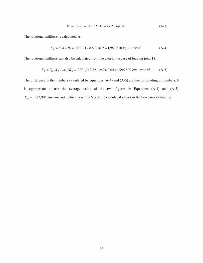
96
7 / 1000/ 21.18 47.21 /z TK F u kip in= = = (A-3)
The rotational stiffness is calculated as
7 7 7/ 1000 319.82/0.1615 1,980,310 /RK F X kip in radθ= = ⋅ = − (A-4)
The rotational stiffness can also be calculated from the data in the case of loading joint 18:
718 18( 240) / 1000 (319.82 240)/0.04 1,995,500 /RK F X kip in radθ− == ⋅ − = − (A-5)
The difference in the numbers calculated by equations (A-4) and (A-5) are due to rounding of numbers. It
is appropriate to use the average value of the two figures in Equations (A-4) and (A-5),
1,987,905 /RK kip in rad= − , which is within 5% of the calculated values in the two cases of loading.

97
APPENDIX B
INPUT TO PROGRAM 3D-BASIS-ME-MB
FOR EXAMPLE OF 7-STORY TESTED MODEL
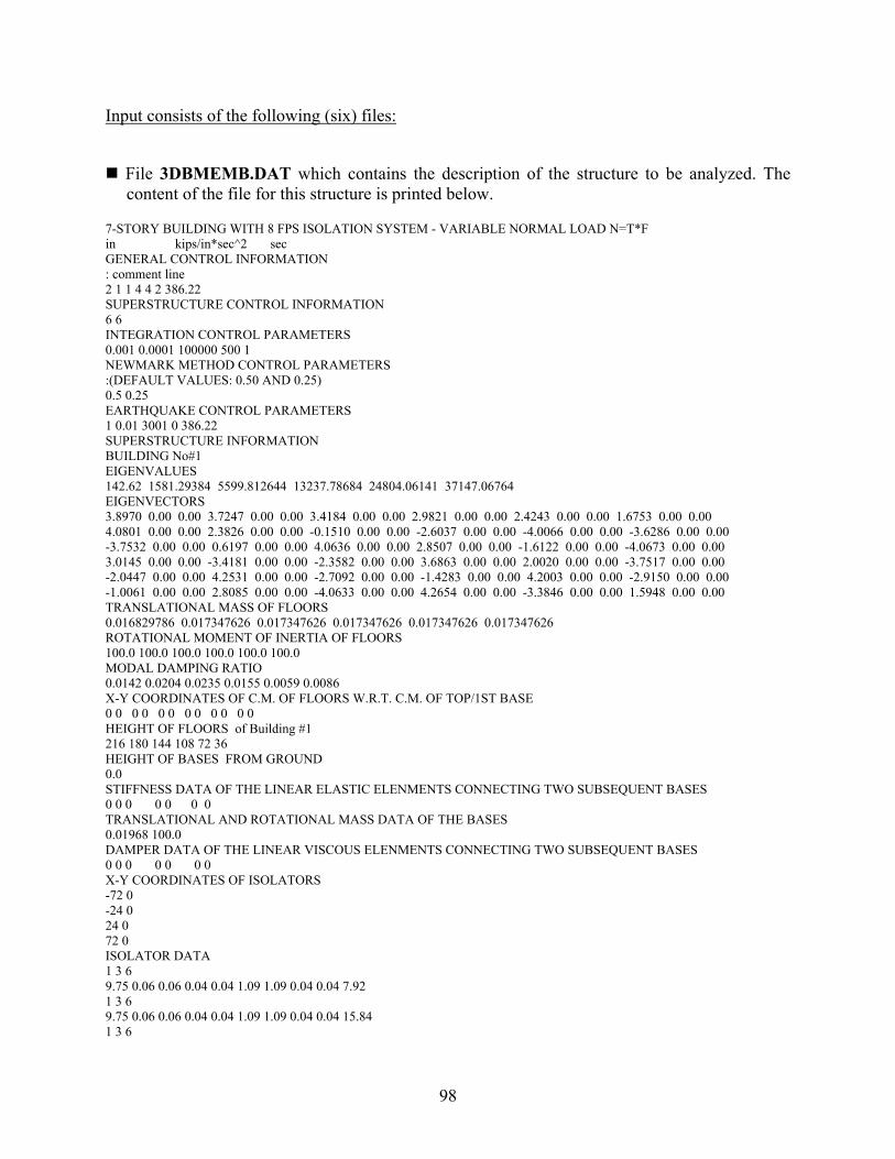
98
Input consists of the following (six) files:
File 3DBMEMB.DAT which contains the description of the structure to be analyzed. The content of the file for this structure is printed below.
7-STORY BUILDING WITH 8 FPS ISOLATION SYSTEM - VARIABLE NORMAL LOAD N=T*F in kips/in*sec^2 sec GENERAL CONTROL INFORMATION : comment line 2 1 1 4 4 2 386.22 SUPERSTRUCTURE CONTROL INFORMATION 6 6 INTEGRATION CONTROL PARAMETERS 0.001 0.0001 100000 500 1 NEWMARK METHOD CONTROL PARAMETERS :(DEFAULT VALUES: 0.50 AND 0.25) 0.5 0.25 EARTHQUAKE CONTROL PARAMETERS 1 0.01 3001 0 386.22 SUPERSTRUCTURE INFORMATION BUILDING No#1 EIGENVALUES 142.62 1581.29384 5599.812644 13237.78684 24804.06141 37147.06764 EIGENVECTORS 3.8970 0.00 0.00 3.7247 0.00 0.00 3.4184 0.00 0.00 2.9821 0.00 0.00 2.4243 0.00 0.00 1.6753 0.00 0.00 4.0801 0.00 0.00 2.3826 0.00 0.00 -0.1510 0.00 0.00 -2.6037 0.00 0.00 -4.0066 0.00 0.00 -3.6286 0.00 0.00 -3.7532 0.00 0.00 0.6197 0.00 0.00 4.0636 0.00 0.00 2.8507 0.00 0.00 -1.6122 0.00 0.00 -4.0673 0.00 0.00 3.0145 0.00 0.00 -3.4181 0.00 0.00 -2.3582 0.00 0.00 3.6863 0.00 0.00 2.0020 0.00 0.00 -3.7517 0.00 0.00 -2.0447 0.00 0.00 4.2531 0.00 0.00 -2.7092 0.00 0.00 -1.4283 0.00 0.00 4.2003 0.00 0.00 -2.9150 0.00 0.00 -1.0061 0.00 0.00 2.8085 0.00 0.00 -4.0633 0.00 0.00 4.2654 0.00 0.00 -3.3846 0.00 0.00 1.5948 0.00 0.00 TRANSLATIONAL MASS OF FLOORS 0.016829786 0.017347626 0.017347626 0.017347626 0.017347626 0.017347626 ROTATIONAL MOMENT OF INERTIA OF FLOORS 100.0 100.0 100.0 100.0 100.0 100.0 MODAL DAMPING RATIO 0.0142 0.0204 0.0235 0.0155 0.0059 0.0086 X-Y COORDINATES OF C.M. OF FLOORS W.R.T. C.M. OF TOP/1ST BASE 0 0 0 0 0 0 0 0 0 0 0 0 HEIGHT OF FLOORS of Building #1 216 180 144 108 72 36 HEIGHT OF BASES FROM GROUND 0.0 STIFFNESS DATA OF THE LINEAR ELASTIC ELENMENTS CONNECTING TWO SUBSEQUENT BASES 0 0 0 0 0 0 0 TRANSLATIONAL AND ROTATIONAL MASS DATA OF THE BASES 0.01968 100.0 DAMPER DATA OF THE LINEAR VISCOUS ELENMENTS CONNECTING TWO SUBSEQUENT BASES 0 0 0 0 0 0 0 X-Y COORDINATES OF ISOLATORS -72 0 -24 0 24 0 72 0 ISOLATOR DATA 1 3 6 9.75 0.06 0.06 0.04 0.04 1.09 1.09 0.04 0.04 7.92 1 3 6 9.75 0.06 0.06 0.04 0.04 1.09 1.09 0.04 0.04 15.84 1 3 6
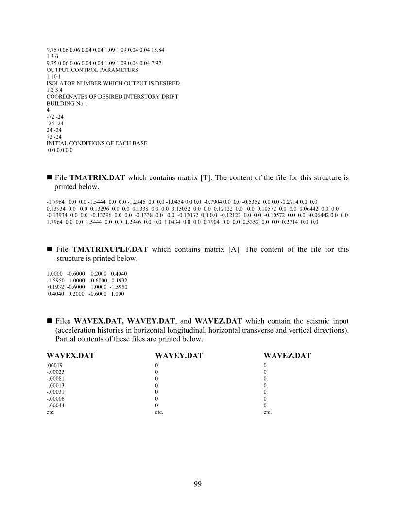
99
9.75 0.06 0.06 0.04 0.04 1.09 1.09 0.04 0.04 15.84 1 3 6 9.75 0.06 0.06 0.04 0.04 1.09 1.09 0.04 0.04 7.92 OUTPUT CONTROL PARAMETERS 1 10 1 ISOLATOR NUMBER WHICH OUTPUT IS DESIRED 1 2 3 4 COORDINATES OF DESIRED INTERSTORY DRIFT BUILDING No 1 4 -72 -24 -24 -24 24 -24 72 -24 INITIAL CONDITIONS OF EACH BASE 0.0 0.0 0.0
File TMATRIX.DAT which contains matrix [T]. The content of the file for this structure is printed below.
-1.7964 0.0 0.0 -1.5444 0.0 0.0 -1.2946 0.0 0.0 -1.0434 0.0 0.0 -0.7904 0.0 0.0 -0.5352 0.0 0.0 -0.2714 0.0 0.0 0.13934 0.0 0.0 0.13296 0.0 0.0 0.1338 0.0 0.0 0.13032 0.0 0.0 0.12122 0.0 0.0 0.10572 0.0 0.0 0.06442 0.0 0.0 -0.13934 0.0 0.0 -0.13296 0.0 0.0 -0.1338 0.0 0.0 -0.13032 0.0 0.0 -0.12122 0.0 0.0 -0.10572 0.0 0.0 -0.06442 0.0 0.0 1.7964 0.0 0.0 1.5444 0.0 0.0 1.2946 0.0 0.0 1.0434 0.0 0.0 0.7904 0.0 0.0 0.5352 0.0 0.0 0.2714 0.0 0.0
File TMATRIXUPLF.DAT which contains matrix [A]. The content of the file for this structure is printed below.
1.0000 -0.6000 0.2000 0.4040 -1.5950 1.0000 -0.6000 0.1932 0.1932 -0.6000 1.0000 -1.5950 0.4040 0.2000 -0.6000 1.000
Files WAVEX.DAT, WAVEY.DAT, and WAVEZ.DAT which contain the seismic input (acceleration histories in horizontal longitudinal, horizontal transverse and vertical directions). Partial contents of these files are printed below.
WAVEX.DAT .00019 -.00025 -.00081 -.00013 -.00031 -.00006 -.00044 etc.
WAVEY.DAT 0 0 0 0 0 0 0 etc.
WAVEZ.DAT 0 0 0 0 0 0 0 etc.

101
APPENDIX C
CONSTRUCTION OF RELATION BETWEEN INERTIA FORCES AND AXIAL
BEARING LOADS IN EXAMPLE OF TESTED 7-STORY MODEL

102
CONSTRUCTION OF RELATION BETWEEN INERTIA FORCES AND AXIAL
BEARING LOADS IN EXAMPLE OF TESTED 7-STORY MODEL
For the 7-story model verification example described in Section 4.2, the coefficient matrices [ ]T
and [ ]A , which are required for accounting for the variation of normal loads on isolators, were
constructed as follows:
• Matrix [ ]T was calculated by static analysis in computer code SAP2000 of a model of
the 7-story structure with all bearings represented as pins.
• Matrix [ ]A was also calculated in a series of four SAP2000 static analyses in which one
of the four supports was removed, an upward unit load was applied at the bearing
location, and the reactions at the remaining three bearings (represented as pins) were
calculated.
Figure C-1 shows the models considered in constructing matrix [ ]T . The reactions in this case,
where a unit force is applied at the 7th floor, correspond to the 1st column of matrix [ ]T . The
complete matrix is obtained in an analogous way by applying the unit force at each floor level.
Matrix [ ]T is presented below:
-1.7964 0 0 1.5444 0 0 1.2946 0 0 1.0434 0 0 0.7904 0 0 0.5352 0 0 0.2714 0 00.1393 0 0 0.1329 0 0 0.1338 0 0 0.1303 0 0 0.1212 0 0 0.1057 0 0 0.0644 0 00.1393 0 0 0.1329 0 0 0.1338 0 0 0.1303 0 0 0.1212 0 0 0.1057 0 0 0.0644 0 0
1.7964 0 0 1.5444 0 0 1.
− − − − − −
− − − − − − −2946 0 0 1.0434 0 0 0.7904 0 0 0.5352 0 0 0.2714 0 0
⎡ ⎤⎢ ⎥⎢ ⎥⎢ ⎥⎢ ⎥⎣ ⎦
Note that several columns in matrix [ ]T have zero values. The zero elements in the matrix
represent reactions at the four supports due to inertia forces acting in the transverse (z) direction
and in the rotational direction (moment about vertical axis). This is necessary since the model in
3D-BASIS-ME-MB is three-dimensional, wheres the analysis performed herein is two-
dimensional. Note that in a three-dimensional analysis of the structure (by including excitation
in the transverse direction or by providing torsional coupling), these elements would not be zero.
Matrix [ ]A was calculated by the procedure described in Section 3.2, which is illustrated in the
schematic of Figure C-2.

103
Figure C-1: Structural model used in constructing matrix [ ]T . (The reaction forces shown
constitute the first column of matrix [ ]T )
Figure C-2: Illustration of procedure used to construct matrix A⎡ ⎤⎣ ⎦ .
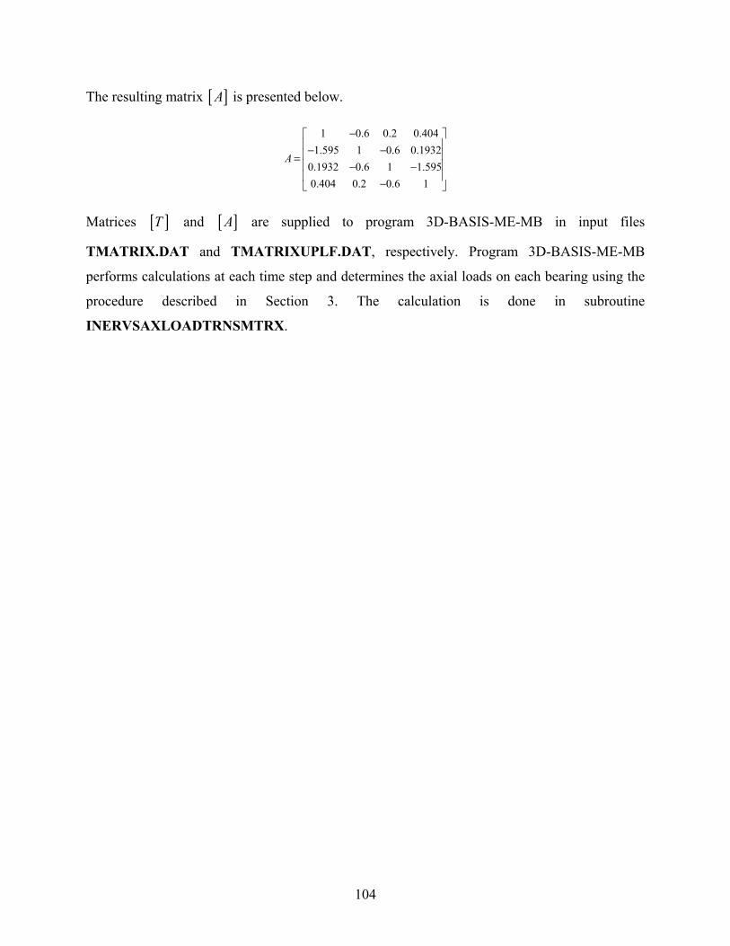
104
The resulting matrix [ ]A is presented below.
1 0.6 0.2 0.4041.595 1 0.6 0.1932
0.1932 0.6 1 1.5950.404 0.2 0.6 1
A
−⎡ ⎤⎢ ⎥− −⎢ ⎥=⎢ ⎥− −⎢ ⎥−⎣ ⎦
Matrices [ ]T and [ ]A are supplied to program 3D-BASIS-ME-MB in input files
TMATRIX.DAT and TMATRIXUPLF.DAT, respectively. Program 3D-BASIS-ME-MB
performs calculations at each time step and determines the axial loads on each bearing using the
procedure described in Section 3. The calculation is done in subroutine
INERVSAXLOADTRNSMTRX.

105
APPENDIX D
COMPARISON OF RESULTS OF PROGRAM 3D-BASIS-ME-MB TO
EXPERIMENTAL RESULTS FOR TESTED 7-STORY MODEL

106
Superstructure Response: El Centro S00E 200% To
tal A
ccel
erat
ion
(g)
-0.6
-0.4
-0.2
0.0
0.2
0.4
0.6
3D-BASIS-ME-MBEXPERIMENTAL
Drif
t (%
)
-0.6
-0.4
-0.2
0.2
0.4
0.6
-0.8
0.0
0.8
X Direction
Time (sec)
0 5 10 15 20 25 30
Shea
r For
ce /
Wei
ght
-0.4-0.3-0.2-0.10.00.10.20.30.4
7th Floor
3rd Story
2nd StoryWeight = 47.6 kip
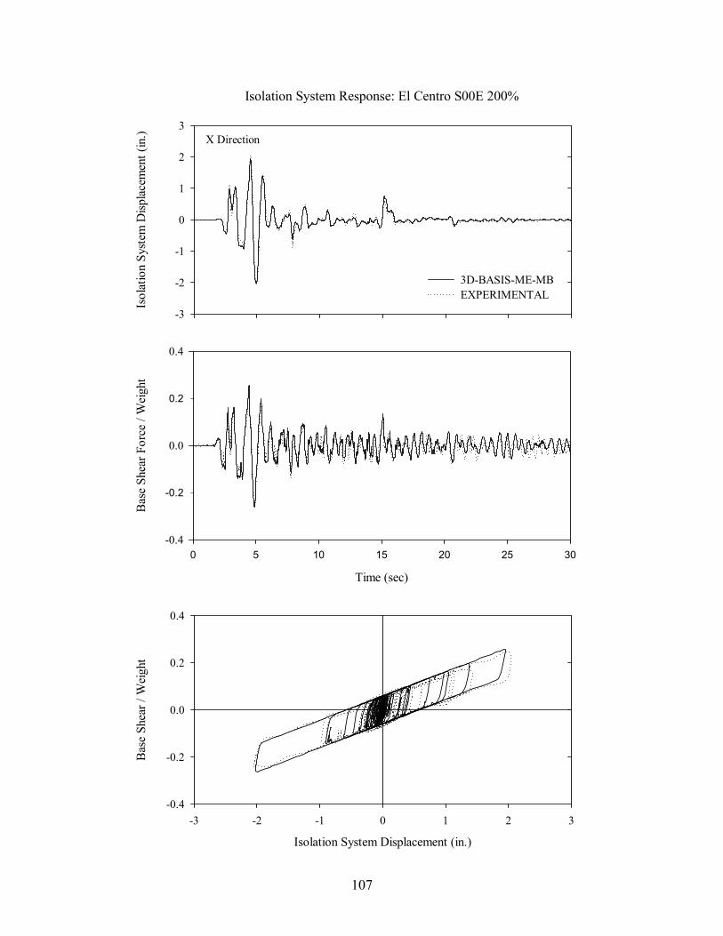
107
Isol
atio
n Sy
stem
Disp
lace
men
t (in
.)
-3
-2
-1
0
1
2
3
3D-BASIS-ME-MBEXPERIMENTAL
Isolation System Response: El Centro S00E 200%
Isolation System Displacement (in.)
-2 -1 1 2-3 0 3
Bas
e Sh
ear /
Wei
ght
-0.2
0.2
-0.4
0.0
0.4
X Direction
Time (sec)
0 5 10 15 20 25 30
Bas
e Sh
ear F
orce
/ W
eigh
t
-0.2
0.2
-0.4
0.0
0.4

108
Time (sec)0 5 10 15 20 25 30
Shea
r For
ce (k
ip)
-4
-2
2
4
0
Individual Bearing Response: El Centro S00E 200%
Disp
lace
men
t (in
)
-3
-2
-1
0
1
2
3
3D-BASIS-ME-MBEXPERIMAENTAL
X Direction
Displacement (in)
-3 -2 -1 1 2 30
Shea
r For
ce (k
ip)
-4
-2
2
4
0
Exterior Bearing (C0)

109
Time (sec)0 5 10 15 20 25 30
Shea
r For
ce (k
ip)
-4
-2
2
4
0
Individual Bearing Response: El Centro S00E 200%
Disp
lace
men
t (in
)
-3
-2
-1
0
1
2
3
3D-BASIS-ME-MBEXPERIMENTAL
X Direction
Displacement (in)
-3 -2 -1 1 2 30
Shea
r For
ce (k
ip)
-4
-2
2
4
0
Interior Bearing (C1)

111
APPENDIX E
COMPARISON OF RESULTS OF PROGRAM ABAQUS TO EXPERIMENTAL
RESULTS FOR TESTED 7-STORY MODEL
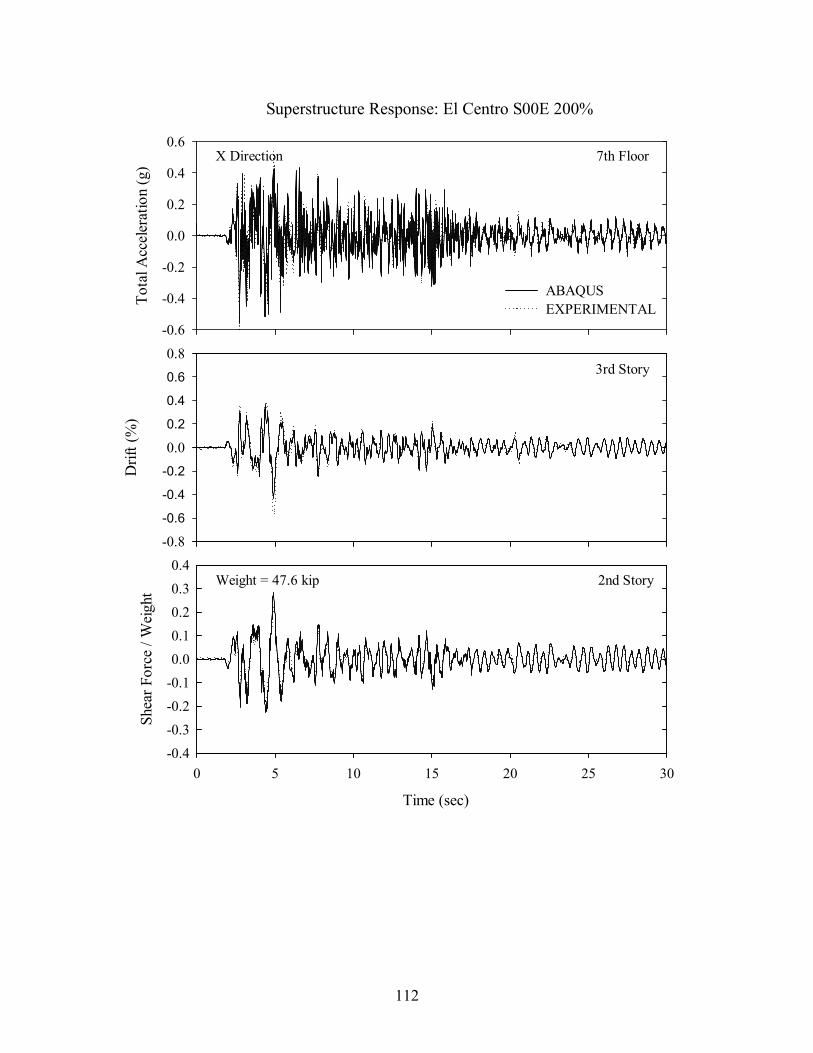
112
Superstructure Response: El Centro S00E 200%
Tota
l Acc
eler
atio
n (g
)
-0.6
-0.4
-0.2
0.0
0.2
0.4
0.6
ABAQUSEXPERIMENTAL
Drif
t (%
)
-0.6
-0.4
-0.2
0.2
0.4
0.6
-0.8
0.0
0.8
X Direction
Time (sec)
0 5 10 15 20 25 30
Shea
r For
ce /
Wei
ght
-0.4-0.3-0.2-0.10.00.10.20.30.4
7th Floor
3rd Story
2nd StoryWeight = 47.6 kip

113
Isol
atio
n Sy
stem
Dis
plac
emen
t (in
.)
-3
-2
-1
0
1
2
3ABAQUSEXPERIMENTAL
Isolation System Response: El Centro S00E 200%
Isolation System Displacement (in.)
-2 -1 1 2-3 0 3
Bas
e Sh
ear /
Wei
ght
-0.2
0.2
-0.4
0.0
0.4
X-Direction
Time (sec)
0 5 10 15 20 25 30
Bas
e Sh
ear F
orce
/ W
eigh
t
-0.2
0.2
-0.4
0.0
0.4

114
Time (sec)0 5 10 15 20 25 30
Shea
r For
ce (k
ip)
-4
-2
2
4
0
Individual Bearing Response: El Centro S00E 200%D
ispl
acem
ent (
in)
-3
-2
-1
0
1
2
3
ABAQUSEXPERIMAENTAL
X-Direction
Displacement (in)
-3 -2 -1 1 2 30
Shea
r For
ce (k
ip)
-4
-2
2
4
0
Exterior Bearing (C0)

115
Time (sec)0 5 10 15 20 25 30
Shea
r For
ce (k
ip)
-4
-2
2
4
0
Individual Bearing Response: El Centro S00E 200%D
ispl
acem
ent (
in)
-3
-2
-1
0
1
2
3
ABAQUSEXPERIMENTAL
X-Direction
Displacement (in)
-3 -2 -1 1 2 30
Shea
r For
ce (k
ip)
-4
-2
2
4
0
Interior Bearing (C1)


117
APPENDIX F
DESCRIPTION OF TWO-TOWER, SPLIT-ISOLATION LEVEL
VERIFICATION MODEL
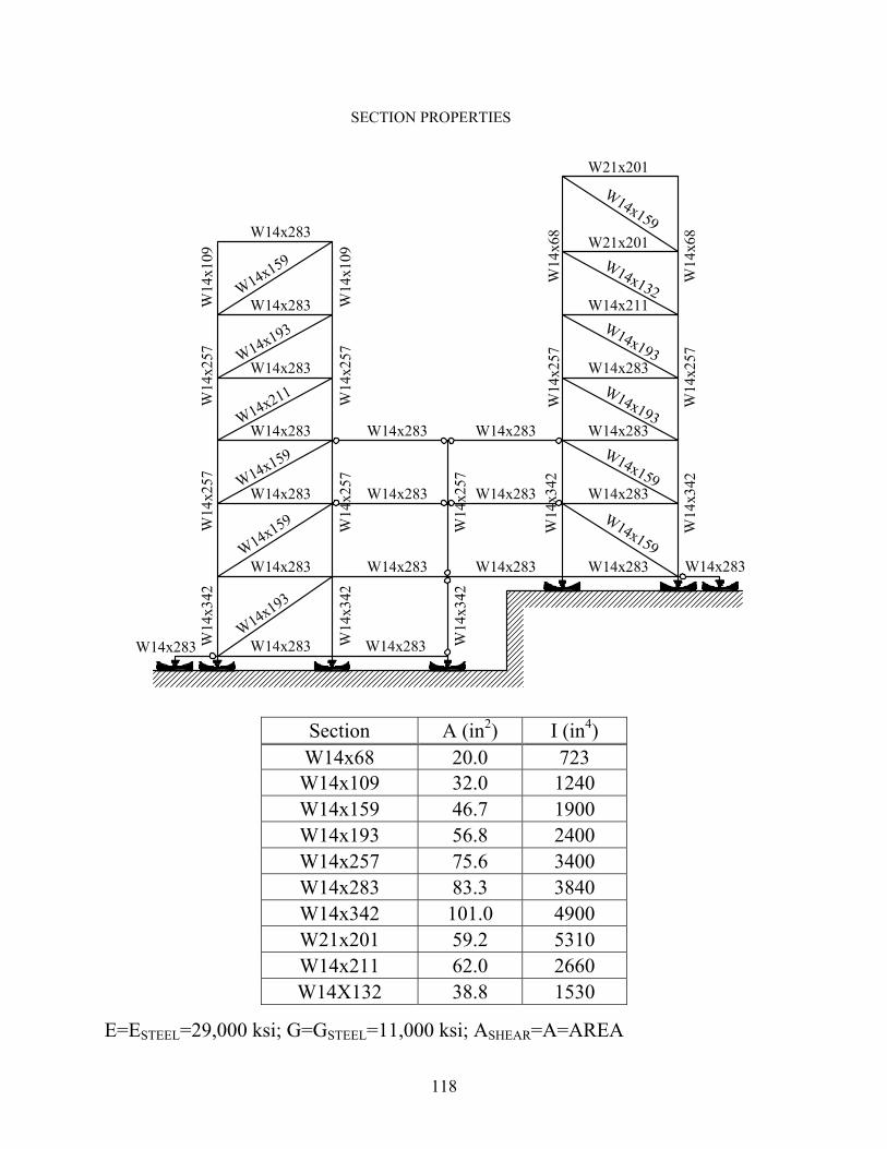
118
Section A (in2) I (in4) W14x68 20.0 723 W14x109 32.0 1240 W14x159 46.7 1900 W14x193 56.8 2400 W14x257 75.6 3400 W14x283 83.3 3840 W14x342 101.0 4900 W21x201 59.2 5310 W14x211 62.0 2660 W14X132 38.8 1530
E=ESTEEL=29,000 ksi; G=GSTEEL=11,000 ksi; ASHEAR=A=AREA

119

120

121
APPENDIX G
INPUT TO PROGRAM 3D-BASIS-ME-MB
FOR TWO-TOWER VERIFICATION MODEL

122
Input consists of the following (six) files:
File 3DBMEMB.DAT which contains the description of the structure to be analyzed. The content of the file for this structure is printed below.
2-Tower Hospital Model 2D 7-FPS ISOLATORS in Kip/in*sec^2 sec GENERAL CONTROL INFORMATION : comment line 2 2 4 7 7 2 386.22 SUPERSTRUCTURE CONTROL INFORMATION 3 3 4 4 INTEGRATION CONTROL PARAMETERS 0.001 0.0001 10000 1000 1 NEWMARK METHOD CONTROL PARAMETERS :(DEFAULT VALUES: 0.50 AND 0.25) 0.5 0.25 EARTHQUAKE CONTROL PARAMETERS : scale factor 386.22 1 0.005 8200 0 386.22 SUPERSTRUCTURE INFORMATION BUILDING No#1 EIGENVALUES :8.82 33.979 59.537 77.79 1154.57 3544.65 EIGENVECTORS 0.5079 0.0000 0.0000 0.3321 0.0000 0.0000 0.1779 0.0000 0.0000 0.2896 0.0000 0.0000 -0.4003 0.0000 0.0000 -0.4916 0.0000 0.0000 0.1036 0.0000 0.0000 -0.5091 0.0000 0.0000 0.5025 0.0000 0.0000 TRANSLATIONAL MASS OF FLOORS 2.846 1.888 1.902 ROTATIONAL MOMENT OF INERTIA OF FLOORS 1.E+6 1.E+6 1.E+6 MODAL DAMPING RATIO 0.02 0.02 0.02 0.02 0.02 0.02 0.02 0.02 0.02 X-Y COORDINATES OF C.M. OF FLOORS W.R.T. C.M. OF TOP/1ST BASE 0.0 0.0 0.0 0.0 0.0 0.0 HEIGHT OF FLOORS of Building #1 99.0 81.5 66.5 BUILDING No#2 EIGENVALUES :6.863 23.937 43.542 60.439 47.10 572.98 1895.91 3652.87 EIGENVECTORS 0.4915 0.0000 0.0000 0.3432 0.0000 0.0000 0.2115 0.0000 0.0000 0.1098 0.0000 0.0000 0.2952 0.0000 0.0000 -0.2425 0.0000 0.0000 -0.4705 0.0000 0.0000 -0.3619 0.0000 0.0000 0.1606 0.0000 0.0000 -0.5625 0.0000 0.0000 0.1230 0.0000 0.0000 0.4167 0.0000 0.0000 0.0295 0.0000 0.0000 -0.2287 0.0000 0.0000 0.5138 0.0000 0.0000 -0.4763 0.0000 0.0000 TRANSLATIONAL MASS OF FLOORS 2.814 1.834 1.834 1.84 ROTATIONAL MOMENT OF INERTIA OF FLOORS 1.E+6 1.E+6 1.E+6 1.E+6 MODAL DAMPING RATIO 0.02 0.02 0.02 0.02 0.02 0.02 0.02 0.02 0.02 0.02 0.02 0.02 X-Y COORDINATES OF C.M. OF FLOORS W.R.T. C.M. OF TOP/1ST BASE 0.0 0.0 0.0 0.0 0.0 0.0 0.0 0.0 HEIGHT OF FLOORS of Building #2 114.5 96.5 81.5 66.5

123
HEIGHT OF BASES FROM GROUND 51.5 36.5 19.0 0.0 STIFFNESS DATA OF THE LINEAR ELASTIC ELENMENTS CONNECTING TWO SUBSEQUENT BASES : ONLY BRACES CONTRIBUTE IN STIFFNESS 4586. 4586. 1.e+15 0.0 0.0 0.0 0.0 4775. 4775. 1.e+15 0.0 0.0 0.0 0.0 2307. 2307. 1.e+15 0.0 0.0 0.0 0.0 0.0 0.0 0.0 0.0 0.0 0.0 0.0 TRANSLATIONAL AND ROTATIONAL MASS DATA OF THE BASES 4.062 1.E8 4.737 1.E8 2.948 1.E8 0.414 1.E8 DAMPER DATA OF THE LINEAR VISCOUS ELENMENTS CONNECTING TWO SUBSEQUENT BASES 14.3 14.3 1.e4 0.0 0.0 0.0 0.0 14.9 14.9 1.e4 0.0 0.0 0.0 0.0 7.2 7.2 1.e4 0.0 0.0 0.0 0.0 0.0 0.0 0.00 0.0 0.0 0.0 0.0 X-Y COORDINATES OF ISOLATORS -65.0 0.0 -55.0 0.0 -27.5 0.0 0.0 0.0 27.5 0.0 55.0 0.0 65.0 0.0 ISOLATOR DATA 4 1 6 169.0 0.07 0.02 0.5 0.004 2819.3 4 1 6 169.0 0.07 0.02 0.5 0.004 534.2 4 1 6 169.0 0.07 0.02 0.5 0.004 534.2 4 1 6 169.0 0.07 0.02 0.5 0.004 1576.0 3 1 6 169.0 0.07 0.02 0.5 0.004 903.2 3 1 6 169.0 0.07 0.02 0.5 0.004 903.2 3 1 6 169.0 0.07 0.02 0.5 0.004 3192.2 OUTPUT CONTROL PARAMETERS 1 10 1 ISOLATOR NUMBER WHICH OUTPUT IS DESIRED 1 2 3 4 5 6 7 COORDINATES OF DESIRED INTERSTORY DRIFT BUILDING No 1 1 0.0 0.0 BUILDING No 2 1 0.0 0.0 INITIAL CONDITIONS OF EACH BASE 0.0 0.0 0.0 0.0 0.0 0.0 0.0 0.0 0.0 0.0 0.0 0.0

124
File TMATRIX.DAT which contains matrix [T]. The content of the file for this structure is printed below.
0.0 0 0 0.0 0 0 0.0 0 0 0.0 0 0 0.0 0 0 0.0 0 0 0.0 0 0 0.0 0 0 0.0 0 0 0.0 0 0 0.0 0 0 -2.39 0 0 -1.85 0 0 -1.39 0 0 -0.97 0 0 -0.93 0 0 -0.90 0 0 -0.86 0 0 -0.87 0 0 -0.63 0 0 -0.32 0 0 0.37 0 0 2.38 0 0 1.84 0 0 1.38 0 0 0.97 0 0 0.93 0 0 0.90 0 0 0.86 0 0 0.87 0 0 0.63 0 0 0.32 0 0 -0.37 0 0 0.0 0 0 0.0 0 0 0.0 0 0 0.0 0 0 0.0 0 0 0.0 0 0 0.0 0 0 0.0 0 0 0.0 0 0 0.0 0 0 0.0 0 0 -0.91 0 0 -0.81 0 0 -0.73 0 0 -2.89 0 0 -2.27 0 0 -1.76 0 0 -1.25 0 0 -0.70 0 0 -0.39 0 0 -0.07 0 0 -0.08 0 0 0.91 0 0 0.81 0 0 0.73 0 0 2.89 0 0 2.27 0 0 1.76 0 0 1.25 0 0 0.70 0 0 0.39 0 0 0.07 0 0 0.08 0 0 0.0 0 0 0.0 0 0 0.0 0 0 0.0 0 0 0.0 0 0 0.0 0 0 0.0 0 0 0.0 0 0 0.0 0 0 0.0 0 0 0.0 0 0
File TMATRIXUPLF.DAT which contains matrix [A]. The content of the file for this structure is printed below.
1.0 0.00 0.00 0.00 0.00 0.00 0.00 0.0 1.00 -0.92 0.24 -0.92 0.98 0.00 0.0 -1.03 1.00 -0.80 0.94 -0.98 0.00 0.0 0.03 -0.10 1.00 -0.07 0.01 0.00 0.0 -0.97 0.88 -0.52 1.00 -1.01 0.00 0.0 0.97 -0.86 0.09 -0.95 1.00 0.00 0.0 0.00 0.00 0.00 0.00 0.00 1.00
Files WAVEX.DAT, WAVEY.DAT, and WAVEZ.DAT which contain the seismic input (acceleration histories in horizontal longitudinal, horizontal transverse and vertical directions). Partial contents of these files are printed below.
WAVEX.DAT -0.004118458 -0.005039125 -0.005097430 -0.004822879 -0.004773737 etc.
WAVEY.DAT 0 0 0 0 0 etc.
WAVEZ.DAT 0 0 0 0 0 etc.

125
APPENDIX H
CONSTRUCTION OF RELATION BETWEEN INERTIA FORCES AND
AXIAL BEARING LOADS IN TWO-TOWER VERIFICATION MODEL
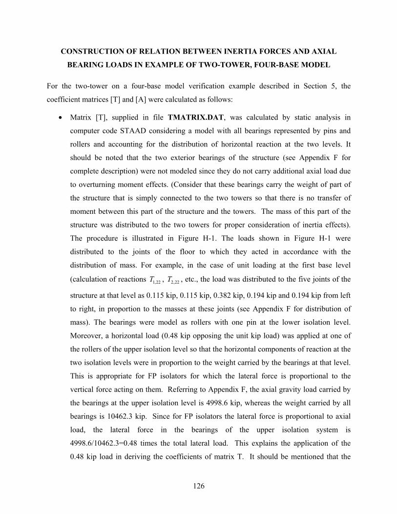
126
CONSTRUCTION OF RELATION BETWEEN INERTIA FORCES AND AXIAL
BEARING LOADS IN EXAMPLE OF TWO-TOWER, FOUR-BASE MODEL
For the two-tower on a four-base model verification example described in Section 5, the
coefficient matrices [T] and [A] were calculated as follows:
• Matrix [T], supplied in file TMATRIX.DAT, was calculated by static analysis in
computer code STAAD considering a model with all bearings represented by pins and
rollers and accounting for the distribution of horizontal reaction at the two levels. It
should be noted that the two exterior bearings of the structure (see Appendix F for
complete description) were not modeled since they do not carry additional axial load due
to overturning moment effects. (Consider that these bearings carry the weight of part of
the structure that is simply connected to the two towers so that there is no transfer of
moment between this part of the structure and the towers. The mass of this part of the
structure was distributed to the two towers for proper consideration of inertia effects).
The procedure is illustrated in Figure H-1. The loads shown in Figure H-1 were
distributed to the joints of the floor to which they acted in accordance with the
distribution of mass. For example, in the case of unit loading at the first base level
(calculation of reactions 1,22T , 2,22T , etc., the load was distributed to the five joints of the
structure at that level as 0.115 kip, 0.115 kip, 0.382 kip, 0.194 kip and 0.194 kip from left
to right, in proportion to the masses at these joints (see Appendix F for distribution of
mass). The bearings were model as rollers with one pin at the lower isolation level.
Moreover, a horizontal load (0.48 kip opposing the unit kip load) was applied at one of
the rollers of the upper isolation level so that the horizontal components of reaction at the
two isolation levels were in proportion to the weight carried by the bearings at that level.
This is appropriate for FP isolators for which the lateral force is proportional to the
vertical force acting on them. Referring to Appendix F, the axial gravity load carried by
the bearings at the upper isolation level is 4998.6 kip, whereas the weight carried by all
bearings is 10462.3 kip. Since for FP isolators the lateral force is proportional to axial
load, the lateral force in the bearings of the upper isolation system is
4998.6/10462.3=0.48 times the total lateral load. This explains the application of the
0.48 kip load in deriving the coefficients of matrix T. It should be mentioned that the

127
derivation of the 0.48 kip figure, it was assumed that the isolator displacements are equal
at each instant of time (which is basically true). Moreover, it was assumed that the ratio
of axial load at the upper isolators to the total weight remains constant at each instant of
time. This is not always approximately true but rather depends on the analyzed structural
system configuration. For the system analyzed herein, bearings 1 and 2, and bearings 4
and 5 act as pairs for which the sum of axial load remains nearly constant during seismic
excitation. That is, the overturning moment created by the inertia forces of the left tower
primarily affect the axial loads on bearing pair 1-2, whereas those of the right tower
affect the axial loads on bearing pair 4-5. The result is that the ratio of lateral load in the
upper isolators to the lateral load in all isolators remains practically constant (herein
calculated as 0.48) even in the presence of bearing uplift.
• Matrix [A], supplied in file TMATRIXUPLF.DAT, was also calculated by static
analysis in program STAAD considering a model with each support successively
removed, a unit load applied at that location and the reactions at the remaining supports
calculated. The supports were modeled as rollers with one pin. The procedure is
illustrated in Figure H-2.
It should be noted that the model displayed in Figures H-1 and H-2 does not contain the two
exterior bearings. These bearings (and the structure above them of which the bearings carry the
weight) are connected to the structure by simple connections so that they do not carry additional
axial as a result of horizontal inertia forces. That is, axial load on these bearings remains constant
when horizontal seismic excitation is applied. Accordingly, these bearings were not included in
the formulation of matrices [T] and [A].
Matrices [T] and [A] are presented below:
1.92 0 0 1.44 0 0 1.03 0 0 0.69 0 0 0.64 0 0 0.60 0 0 0.57 0 0 0.56 0 0 0.35 0 0 0.13 0 0 0.02 0 01.92 0 0 1.44 0 0 1.03 0 0 0.69 0 0 0.64 0 0 0.60 0 0 0.57 0 0 0.56 0 0 0.35 0 0 0.12 0 0 0.03 0 0
0 0 0 0 0 0 0 0 0 0 0 0 0 0 0 0 0 0 0 0 0 0 0 0 0 0 0 0 0 0 0.01 0 00.97 0 0 0.87 0 0
T =
− − − − − − − − − −−
− − −
⎡ ⎤⎣ ⎦
0.77 0 0 2.92 0 0 2.13 0 0 1.80 0 0 1.29 0 0 0.74 0 0 0.42 0 0 0.08 0 0 0.01 0 00.97 0 0 0.87 0 0 0.77 0 0 2.92 0 0 2.31 0 0 1.80 0 0 1.29 0 0 0.74 0 0 0.42 0 0 0.09 0 0 0.01 0 0
− − − − − − − −
⎡ ⎤⎢ ⎥⎢ ⎥⎢ ⎥⎣ ⎦
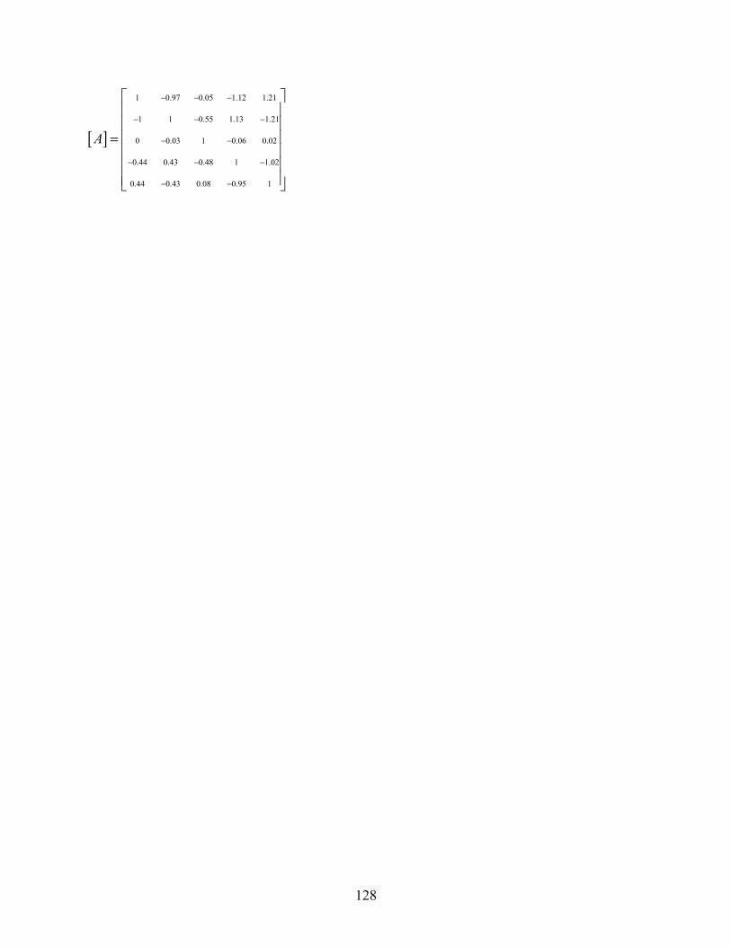
128
[ ]
1 0.97 0.05 1.12 1.21
1 1 0.55 1.13 1.21
0 0.03 1 0.06 0.02
0.44 0.43 0.48 1 1.02
0.44 0.43 0.08 0.95 1
A
− − −
− − −
− −
− − −
− −
⎡ ⎤⎢ ⎥⎢ ⎥⎢ ⎥=⎢ ⎥⎢ ⎥⎢ ⎥⎣ ⎦

129
Figu
re H
-1: S
truct
ural
mod
el u
sed
in c
onst
ruct
ion
of m
atrix
[]
T
T 1,1
0
T 1,1
T 2,1 T 3
1
T 5,1
T 4,1
1 2
3 4
5
1
T 1,4
T 2,4 T 3
,4
T 5,4
T 4,4
12
3
45
1
T 1,7
T 2,7 T 3
,7
T 5,7
T 4,7
12
3
45
1
T 5,1
0 T 5
,13
T 2,1
0 T 3,1
0 T 4,1
0 1
2 3 4
5
1
T 1,1
3 T 2
,13 T 3
,13 T 4
,13
1 2
3
45
1
T 1,1
6 T 2
,16 T 3
,16
T 5,1
6 T 4
,16
12
3
45
1
T 1,1
9 T 2
,19 T 3
,19
T 5,1
9 T 4
,19
12
3
45
1
0.48
0.48
0.48
0.48
0.48
0.
480.
48

130
Figu
re H
-1 C
ontin
ued
T 1,3
1 T 2
,31
T 3,3
1 T 5
,31
T 4,3
1 1
2 3 4
51
T 1,2
8 T 2
,28
T 3,2
8 T 5
,28
T 4,2
8 1
23
45
1
T 1,2
2 T 2
,22
T 3,2
2 T 4,2
2 1
2 3
4 5
1
T 5,2
2
T 1,2
5 T 2
,25
T 3,2
5 T 4,2
5 1
23
45
1
T 5,2
5
0.48
0.48
0.
48
0.48
131
Figure H-2: Structural models used in construction of matrix [A]
A11 =1
A21 A31
A51 A41
A12
A22=1
A32
A52 A42
A13 A23
A33=1 A53 A43
A14
A44=1
A34
A54
A24
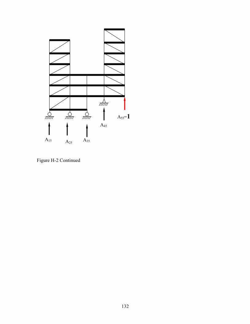
132
Figure H-2 Continued
A15
A55=1
A35
A45
A25

133
APPENDIX I
CALCULATION OF INPUT PARAMETERS
FOR SUPERSTRUCTURE OF TWO-TOWER EXAMPLE

134
CALCULATION OF INPUT PARAMETERS FOR SUPERSTRUCTURE OF
TWO-TOWER EXAMPLE
Input parameters for the description of the isolated superstructure in 3D-BASIS-ME-MB
include the stiffness, mass and damping properties of each of the two towers (termed
superstructures) and the stiffness, mass and damping properties of each of the stories
below the two towers(termed the bases). In this example, there are two superstructures
(left and right towers, respectively of 3 and 4 stories) and four bases. The bases are
numbered 1, 2, 3 and 4 starting from the one at the top. Information on the two
superstructures (towers) was input in the form of floor masses, mode shapes, frequencies
and damping ratios (best way of describing properties). For the four bases (stories below
the towers), the parameters were input as mass, shear stiffness and damping constant. For
example, for base 1, the input consisted of the mass at the level of joints 4-11-18-21-28
(see Figure I-1) and the stiffness K1 and damping constant C1 for the story below the
mass. (Note that the joint numbering mentioned above was not used in 3D-BASIS-ME-
MB but rather used only in program STAAD in the model to calculate various stiffness
parameters as described below).
The structure was modeled in computer program STAAD in order to calculate the
stiffness parameters needed to input in program 3D-BASIS-ME-MB. Figure I-1 shows
the model.

135
Figure I-1: Model of two-tower example structure in program STAAD.
Right Tower
To obtain the stiffness properties of the right tower (a similar approach was followed for
the left tower), unit displacements of the four floors of the right tower were imposed and
the forces needed to impose these displacements were calculated while all joints were
restrained against lateral movement. The input file to program STAAD to achieve this is
presented in Table I-1.
Table I-1: Input to program STAAD.
STAAD PLANE TWO-TOWER * INPUT WIDTH 79 PAGE LENGTH 50 UNITS FEET KIP JOINT COORDINATES 1 0 0; 2 0 19; 3 0 36.5; 4 0 51.5; 5 0 66.5; 6 0 81.5;7 0 99; 8 27.5 0; 9 27.5 19; 10 27.5 36.5; 11 27.5 51.5; 12 27.5 66.5; 13 27.5 81.5; 14 27.5 99; 15 55 0; 16 55 19; 17 55 36.5; 18 55 51.5; 19 82.5 19; 20 82.5 36.5;21 82.5 51.5;22 82.5 66.5;23 82.5 81.5;24 82.5 96.5;

136
25 82.5 114.5; 26 110 19;27 110 36.5;28 110 51.5;29 110 66.5;30 110 81.5;31 110 96.5; 32 110 114.5 33 0 -1;34 27.5 -1;35 55 -1;36 82.5 18; 37 110 18 MEMBER INCIDENCES 1 1 2 6; 7 8 9 12; 13 15 16 15; 16 19 20 21; 22 26 27 27; 28 1 8; 29 8 15; 30 2 9;31 9 16;32 16 19;33 19 26; 34 3 10;35 10 17;36 17 20;37 20 27; 38 4 11;39 11 18;40 18 21;41 21 28 42 5 12; 43 6 13; 44 7 14; 45 22 29; 46 23 30; 47 24 31; 48 25 32; 49 1 9 54; 55 20 26 60 61 1 33;62 8 34;63 15 35;64 19 36;65 26 37 MEMBER PROPERTY AMERICAN 1 7 13 16 17 22 23 TABLE ST W14X342 2 TO 5 8 TO 11 14 15 18 19 24 25 TABLE ST W14X257 6 12 TABLE ST W14X109 20 21 26 27 TABLE ST W14X68 28 TO 45 TABLE ST W14X283 46 TABLE ST W14X211 47 48 TABLE ST W21X201 49 TABLE ST W14X193 50 51 54 55 56 60 TABLE ST W14X159 52 TABLE ST W14X211 53 57 58 TABLE ST W14X193 59 TABLE ST W14X132 *1 FOOT TALL BEARINGS 61 TO 65 TABLE ST W14X342 * MEMBER TRUSS 13 35 36 39 40 MEMBER RELEASES 14 START MZ CONSTANTS E STEEL ALL POISSON STEEL ALL SUPPORTS 33 TO 37 PINNED * * CONSTRUCTION OF STIFFNESS MATRIX OF RIGHT TOWER * *FLOORS RESTRAINED AGAINST LATERAL MOVEMENT 16 17 18 FIXED BUT FY MZ 14 13 12 25 24 23 22 FIXED BUT FY MZ * UNITS INCH *SUPPORT MOVEMENTS LOAD 1 SUPPORT DISPL 25 FX 1 LOAD 2
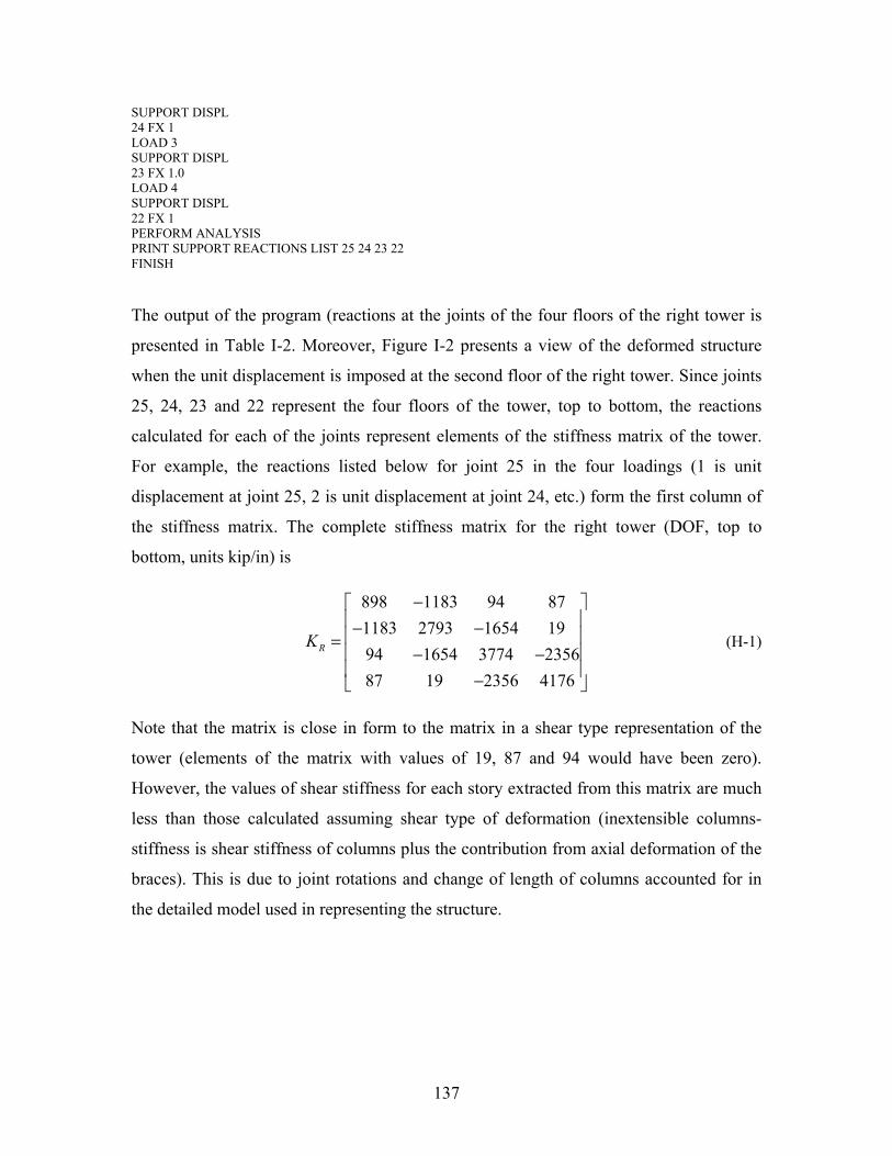
137
SUPPORT DISPL 24 FX 1 LOAD 3 SUPPORT DISPL 23 FX 1.0 LOAD 4 SUPPORT DISPL 22 FX 1 PERFORM ANALYSIS PRINT SUPPORT REACTIONS LIST 25 24 23 22 FINISH
The output of the program (reactions at the joints of the four floors of the right tower is
presented in Table I-2. Moreover, Figure I-2 presents a view of the deformed structure
when the unit displacement is imposed at the second floor of the right tower. Since joints
25, 24, 23 and 22 represent the four floors of the tower, top to bottom, the reactions
calculated for each of the joints represent elements of the stiffness matrix of the tower.
For example, the reactions listed below for joint 25 in the four loadings (1 is unit
displacement at joint 25, 2 is unit displacement at joint 24, etc.) form the first column of
the stiffness matrix. The complete stiffness matrix for the right tower (DOF, top to
bottom, units kip/in) is
898 1183 94 871183 2793 1654 1994 1654 3774 235687 19 2356 4176
RK
−⎡ ⎤⎢ ⎥− −⎢ ⎥=⎢ ⎥− −⎢ ⎥−⎣ ⎦
(H-1)
Note that the matrix is close in form to the matrix in a shear type representation of the
tower (elements of the matrix with values of 19, 87 and 94 would have been zero).
However, the values of shear stiffness for each story extracted from this matrix are much
less than those calculated assuming shear type of deformation (inextensible columns-
stiffness is shear stiffness of columns plus the contribution from axial deformation of the
braces). This is due to joint rotations and change of length of columns accounted for in
the detailed model used in representing the structure.
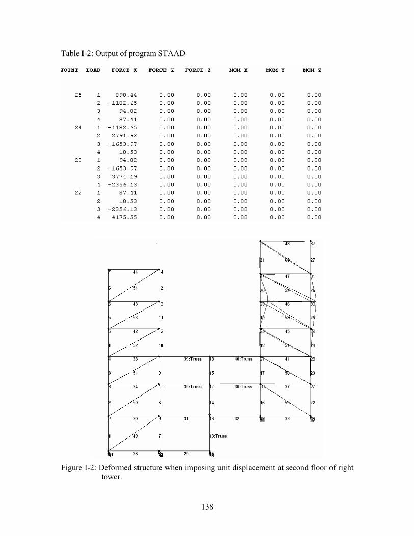
138
Table I-2: Output of program STAAD
Figure I-2: Deformed structure when imposing unit displacement at second floor of right
tower.
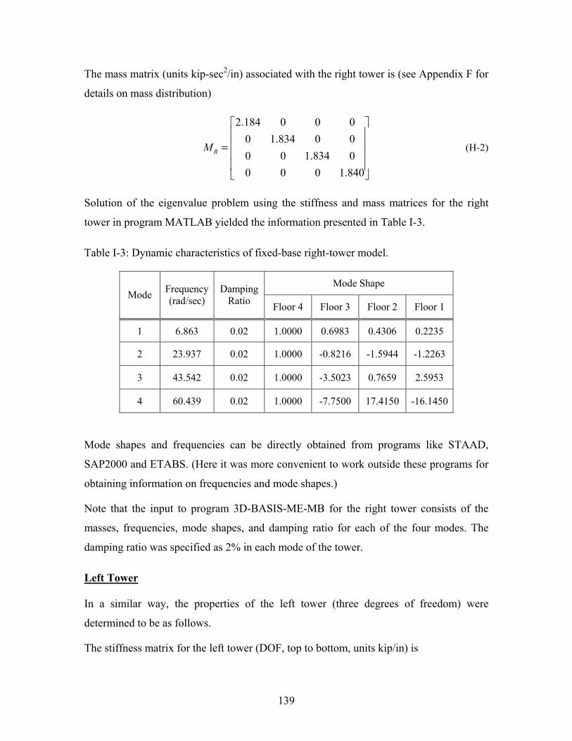
139
The mass matrix (units kip-sec2/in) associated with the right tower is (see Appendix F for
details on mass distribution)
2.184 0 0 00 1.834 0 00 0 1.834 00 0 0 1.840
RM
⎡ ⎤⎢ ⎥⎢ ⎥=⎢ ⎥⎢ ⎥⎣ ⎦
(H-2)
Solution of the eigenvalue problem using the stiffness and mass matrices for the right
tower in program MATLAB yielded the information presented in Table I-3.
Table I-3: Dynamic characteristics of fixed-base right-tower model.
Mode Shape Mode Frequency
(rad/sec) Damping
Ratio Floor 4 Floor 3 Floor 2 Floor 1
1 6.863 0.02 1.0000 0.6983 0.4306 0.2235
2 23.937 0.02 1.0000 -0.8216 -1.5944 -1.2263
3 43.542 0.02 1.0000 -3.5023 0.7659 2.5953
4 60.439 0.02 1.0000 -7.7500 17.4150 -16.1450
Mode shapes and frequencies can be directly obtained from programs like STAAD,
SAP2000 and ETABS. (Here it was more convenient to work outside these programs for
obtaining information on frequencies and mode shapes.)
Note that the input to program 3D-BASIS-ME-MB for the right tower consists of the
masses, frequencies, mode shapes, and damping ratio for each of the four modes. The
damping ratio was specified as 2% in each mode of the tower.
Left Tower
In a similar way, the properties of the left tower (three degrees of freedom) were
determined to be as follows.
The stiffness matrix for the left tower (DOF, top to bottom, units kip/in) is

140
1246 1647 1461647 3965 2424146 2424 4256
LK−⎡ ⎤
⎢ ⎥= − −⎢ ⎥⎢ ⎥−⎣ ⎦
(H-3)
The mass matrix (units kip-sec2/in) associated with the left tower is
2.836 0 0
0 1.888 00 0 1.902
LM⎡ ⎤⎢ ⎥= ⎢ ⎥⎢ ⎥⎣ ⎦
(H-4)
Table I-4 lists the dynamic characteristics of the left tower in terms of natural
frequencies, damping ratios, and mode shapes.
Table I-4: Dynamic characteristics of fixed-base left-tower model.
Mode Shape Mode Frequency
(rad/sec) Damping
Ratio Floor 3 Floor 2 Floor 1
1 8.820 0.02 1.0000 0.6537 0.3502
2 33.979 0.02 1.0000 -1.3819 -1.6971
3 59.537 0.02 1.0000 -4.9156 4.8514
Story Below First Base
The calculation of stiffness K1 of the story below the first base (see Figure I-1) was based
on restraining the lateral movement of all nodes below the first base, imposing a
distributed (based on mass distribution) 1000-kip load at the first base level (joints 4, 11,
18, 21 and 28), and calculating the average displacement of these joints.
The input file to program STAAD is presented in Table I-5 and the deformed structure is
shown in Figure I-3. The calculated displacements at the joints of the floor ranged from
0.2010 to 0.2333 in., with the average being 0.2180 in. The story stiffness was then
calculated as K1 = 1000 kip / 0.21807 in = 4586 kip/in.
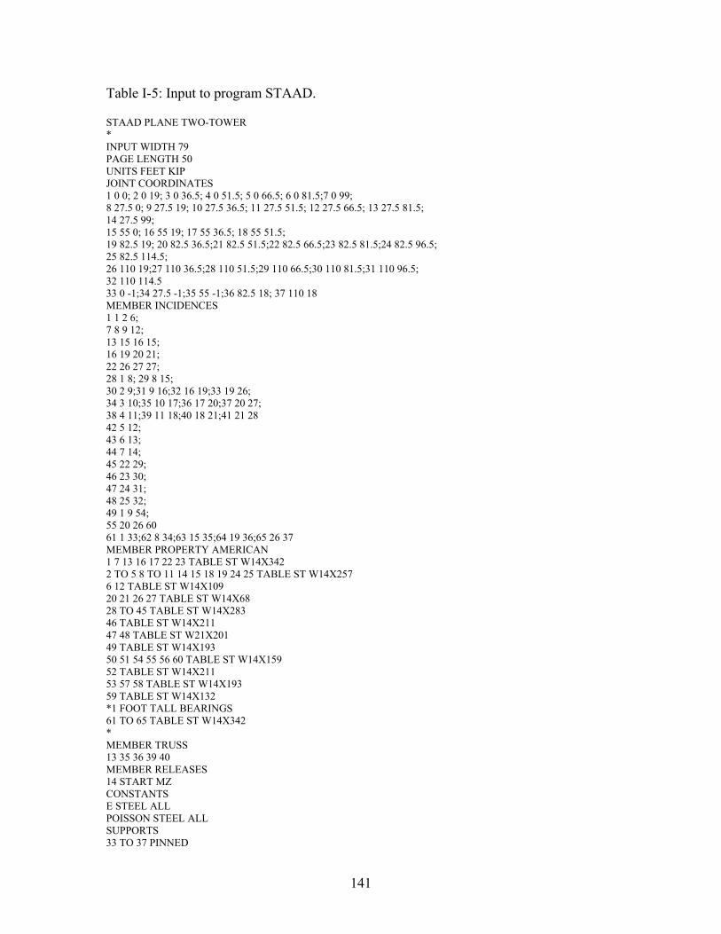
141
Table I-5: Input to program STAAD.
STAAD PLANE TWO-TOWER * INPUT WIDTH 79 PAGE LENGTH 50 UNITS FEET KIP JOINT COORDINATES 1 0 0; 2 0 19; 3 0 36.5; 4 0 51.5; 5 0 66.5; 6 0 81.5;7 0 99; 8 27.5 0; 9 27.5 19; 10 27.5 36.5; 11 27.5 51.5; 12 27.5 66.5; 13 27.5 81.5; 14 27.5 99; 15 55 0; 16 55 19; 17 55 36.5; 18 55 51.5; 19 82.5 19; 20 82.5 36.5;21 82.5 51.5;22 82.5 66.5;23 82.5 81.5;24 82.5 96.5; 25 82.5 114.5; 26 110 19;27 110 36.5;28 110 51.5;29 110 66.5;30 110 81.5;31 110 96.5; 32 110 114.5 33 0 -1;34 27.5 -1;35 55 -1;36 82.5 18; 37 110 18 MEMBER INCIDENCES 1 1 2 6; 7 8 9 12; 13 15 16 15; 16 19 20 21; 22 26 27 27; 28 1 8; 29 8 15; 30 2 9;31 9 16;32 16 19;33 19 26; 34 3 10;35 10 17;36 17 20;37 20 27; 38 4 11;39 11 18;40 18 21;41 21 28 42 5 12; 43 6 13; 44 7 14; 45 22 29; 46 23 30; 47 24 31; 48 25 32; 49 1 9 54; 55 20 26 60 61 1 33;62 8 34;63 15 35;64 19 36;65 26 37 MEMBER PROPERTY AMERICAN 1 7 13 16 17 22 23 TABLE ST W14X342 2 TO 5 8 TO 11 14 15 18 19 24 25 TABLE ST W14X257 6 12 TABLE ST W14X109 20 21 26 27 TABLE ST W14X68 28 TO 45 TABLE ST W14X283 46 TABLE ST W14X211 47 48 TABLE ST W21X201 49 TABLE ST W14X193 50 51 54 55 56 60 TABLE ST W14X159 52 TABLE ST W14X211 53 57 58 TABLE ST W14X193 59 TABLE ST W14X132 *1 FOOT TALL BEARINGS 61 TO 65 TABLE ST W14X342 * MEMBER TRUSS 13 35 36 39 40 MEMBER RELEASES 14 START MZ CONSTANTS E STEEL ALL POISSON STEEL ALL SUPPORTS 33 TO 37 PINNED
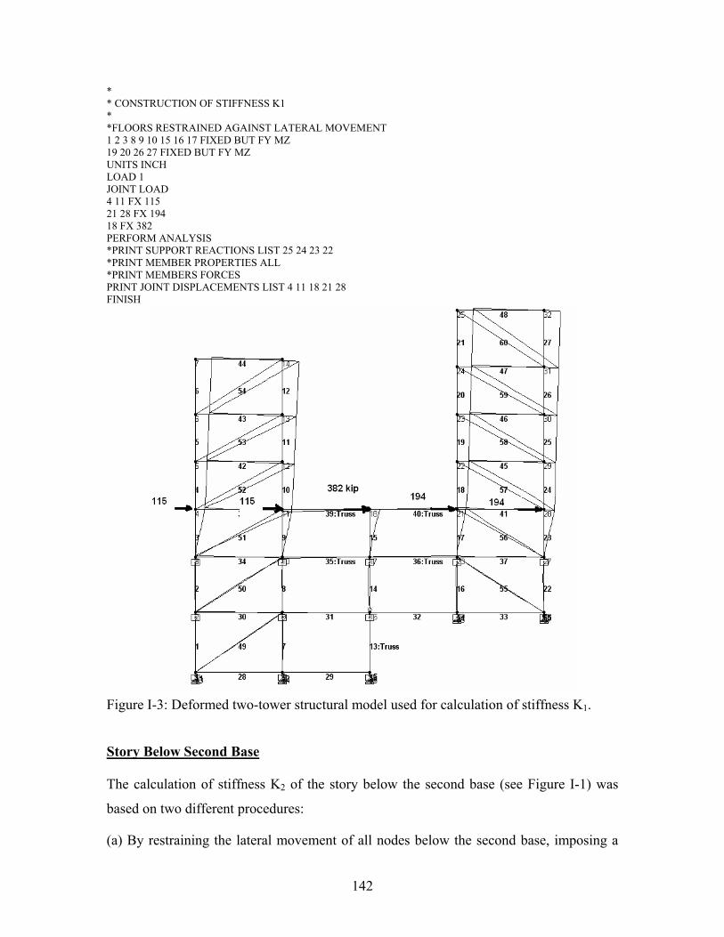
142
* * CONSTRUCTION OF STIFFNESS K1 * *FLOORS RESTRAINED AGAINST LATERAL MOVEMENT 1 2 3 8 9 10 15 16 17 FIXED BUT FY MZ 19 20 26 27 FIXED BUT FY MZ UNITS INCH LOAD 1 JOINT LOAD 4 11 FX 115 21 28 FX 194 18 FX 382 PERFORM ANALYSIS *PRINT SUPPORT REACTIONS LIST 25 24 23 22 *PRINT MEMBER PROPERTIES ALL *PRINT MEMBERS FORCES PRINT JOINT DISPLACEMENTS LIST 4 11 18 21 28 FINISH
Figure I-3: Deformed two-tower structural model used for calculation of stiffness K1.
Story Below Second Base
The calculation of stiffness K2 of the story below the second base (see Figure I-1) was
based on two different procedures:
(a) By restraining the lateral movement of all nodes below the second base, imposing a

143
distributed (based on mass distribution) 1000-kip load at the second base level (joints 3,
10, 17, 20 and 27), and calculating the average displacement of these joints. The loads at
these joints were 107, 107, 382, 202, and 202 kip, respectively.
The deformed structure is shown in Figure I-4. The calculated displacements at the joints
of the floor ranged from 0.2133 to 0.2492 in., with the average being 0.23153 in. The
story stiffness was then calculated as K2 = 1000 kip / 0.23153 in = 4319 kip/in.
Figure I-4: Deformed two-tower structural model used for calculation of stiffness K1.
(b) By restraining the lateral movement of all nodes below and above the second base
(except those of the two towers), imposing a distributed (based on mass distribution)
1000-kip load at the second base level (joints 3, 10, 17, 20 and 27), and calculating the
average displacement of these joints. The loads at these joints were 107, 107, 382, 202
and 202 kip, respectively. The resulting stiffness is the sum K1 + K2, from where K2 can
be calculated.
The deformed structure is shown in Figure I-5. The calculated displacements at the joints
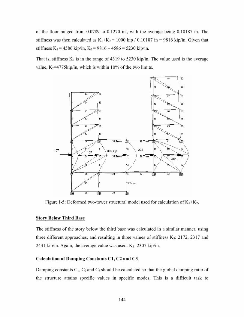
144
of the floor ranged from 0.0789 to 0.1270 in., with the average being 0.10187 in. The
stiffness was then calculated as K1+K2 = 1000 kip / 0.10187 in = 9816 kip/in. Given that
stiffness K1 = 4586 kip/in, K2 = 9816 – 4586 = 5230 kip/in.
That is, stiffness K2 is in the range of 4319 to 5230 kip/in. The value used is the average
value, K2=4775kip/in, which is within 10% of the two limits.
Figure I-5: Deformed two-tower structural model used for calculation of K1+K2.
Story Below Third Base
The stiffness of the story below the third base was calculated in a similar manner, using
three different approaches, and resulting in three values of stiffness K3: 2172, 2317 and
2431 kip/in. Again, the average value was used: K3=2307 kip/in.
Calculation of Damping Constants C1, C2 and C3
Damping constants C1, C2 and C3 should be calculated so that the global damping ratio of
the structure attains specific values in specific modes. This is a difficult task to

145
accomplish given the way damping is specified for the superstructures (towers) in
program 3D-BASIS-ME-MB and the complex eigenvalue procedures required to
calculate damping ratios.
The structure with all supports pinned was analyzed and the frequencies were calculated.
It was chosen to construct the stiffness matrix of the structure using program STAAD and
then perform the eigenvalue analysis in MATLAB. When the bearings are pinned, the
structure has nine effective degrees of freedom, which are selected to be the lateral
displacements of the floors, starting from the right tower, top to bottom(4 degrees),
followed by the left tower, top to bottom (3 degrees) and then the first and second bases.
The global stiffness matrix, in units of kip/in, is
898 1183 94 87 0 0 0 41 29
1183 2793 1654 19 0 0 0 11 7
94 1654 3774 2356 0 0 0 63 38
87 19 2356 4176 0 0 0 1587 279
0 0 0 0 1246 1647 146 93 69
0 0 0 0 1647 3965 2424 46 26
0 0 0 0 146 2424 4259 1655 298
41 11 63 1587 93 46 1655 5287 1894
29 7 38 279 69 26
K
−
− −
− −
− − −
−
− −
− − −
− − −
−
=298 1894 4860
4 1 6 11 43 16 34 155 1165
898 1183 94 87 0 0 0 41 29
1183 2793 1654 19 0 0 0 11 7
94 1654 3774 2356 0 0 0 63 38
87 19 2356 4176 0 0 0 1587 279
0 0 0 0 1246 1647 146 93 69
0 0 0 0 1647 3965 2424 46 26
0 0 0 0 146 2424 4259 1655 298
41 11 63 15
− −
− − − −
−
− −
− −
− − −
−
− −
− − −
− 87 93 46 1655 5287 1894
29 7 38 279 69 26 298 1894 4860
− −
− − −
⎡ ⎤⎢ ⎥⎢ ⎥⎢ ⎥⎢ ⎥⎢ ⎥⎢ ⎥⎢ ⎥⎢ ⎥⎢ ⎥⎢ ⎥⎢ ⎥⎢ ⎥⎢ ⎥⎢ ⎥⎢ ⎥⎢ ⎥⎢ ⎥⎢ ⎥⎢ ⎥⎢ ⎥⎢ ⎥⎢ ⎥⎢ ⎥⎢ ⎥⎢ ⎥⎢ ⎥⎢ ⎥⎢ ⎥⎣ ⎦
(H-5)
and the global mass matrix, in units of kip-sec2/in, is

146
2.814 0 0 0 0 0 0 0 0
0 1.834 0 0 0 0 0 0 0
0 0 1.834 0 0 0 0 0 0
0 0 0 1.840 0 0 0 0 0
0 0 0 0 2.836 0 0 0 0
0 0 0 0 0 1.888 0 0 0
0 0 0 0 0 0 1.902 0 0
0 0 0 0 0 0 0 4.062 0
0 0 0 0 0 0 0 0 4.737
M
⎡ ⎤⎢ ⎥⎢ ⎥⎢ ⎥⎢ ⎥⎢ ⎥⎢ ⎥=⎢ ⎥⎢ ⎥⎢ ⎥⎢ ⎥⎢ ⎥⎢ ⎥⎣ ⎦
(H-6)
Eigenvalue analysis resulted in the following frequencies in units of rad/sec:
[5.495, 7.849, 17.661, 26.565, 34.164, 39.912, 45.429, 59.880, 61.291].
Constructing the damping matrix [C] based on the Rayleigh approach,
1 2[ ] [ ] [ ]C a M a K= + (H-7)
where [M] and [K] are the mass and stiffness matrices of (H-6) and (H-5), respectively.
Parameters 1a and 2a were selected so that the damping ratio in the first two modes is
matched, that is:
2 2
1 1 2 2 2 11 2 2
2 1
2 2a ξ ω ω ξ ω ωω ω
−=−
(H-8)
2 2 1 12 2 2
2 1
2 2a ξ ω ξ ωω ω
−=−
(H-9)
Using 1 2 0.02= =ξ ξ , 1 5.45 /secradω = and 2 7.84 /secradω = , we calculate 1 0.1286a =
and 2 0.003a = . The damping constants iC , 1 or 2i = were calculated as
1 2i i iC a M a K= + (H-10)
147
APPENDIX J
COMPARISON OF RESULTS OF PROGRAM 3D-BASIS-ME-MB TO RESULTS
OF PROGRAM ABAQUS FOR TWO-TOWER VERIFICATION MODEL
(CASE OF FRICTION COEFFICIENT max 0.07f = )
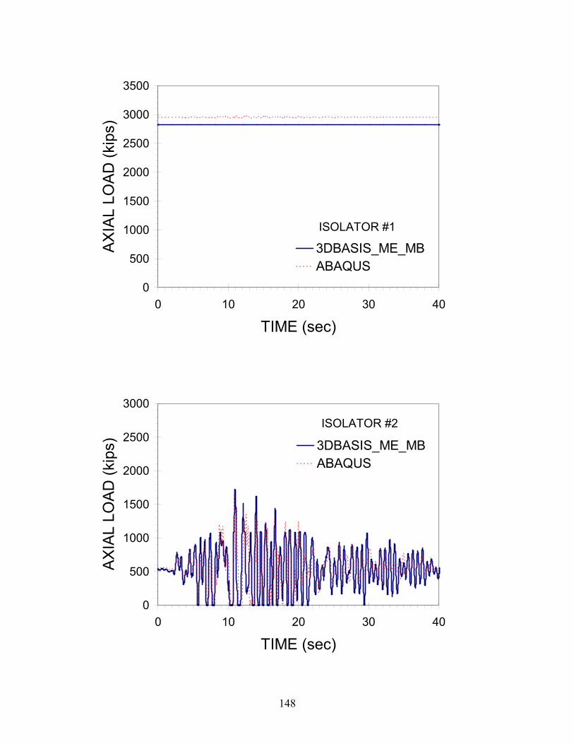
148
0
500
1000
1500
2000
2500
3000
3500
0 10 20 30 40
TIME (sec)
AX
IAL
LOA
D (k
ips)
3DBASIS_ME_MBABAQUS
ISOLATOR #1
0
500
1000
1500
2000
2500
3000
0 10 20 30 40
TIME (sec)
AX
IAL
LOA
D (k
ips) 3DBASIS_ME_MB
ABAQUS
ISOLATOR #2

149
0
500
1000
1500
2000
2500
3000
0 10 20 30 40
TIME (sec)
AX
IAL
LOA
D (k
ips) 3DBASIS_ME_MB
ABAQUS
ISOLATOR #3
0
500
1000
1500
2000
2500
3000
0 10 20 30 40
TIME (sec)
AX
IAL
LOA
D (k
ips) 3DBASIS_ME_MB
ABAQUS
ISOLATOR #4
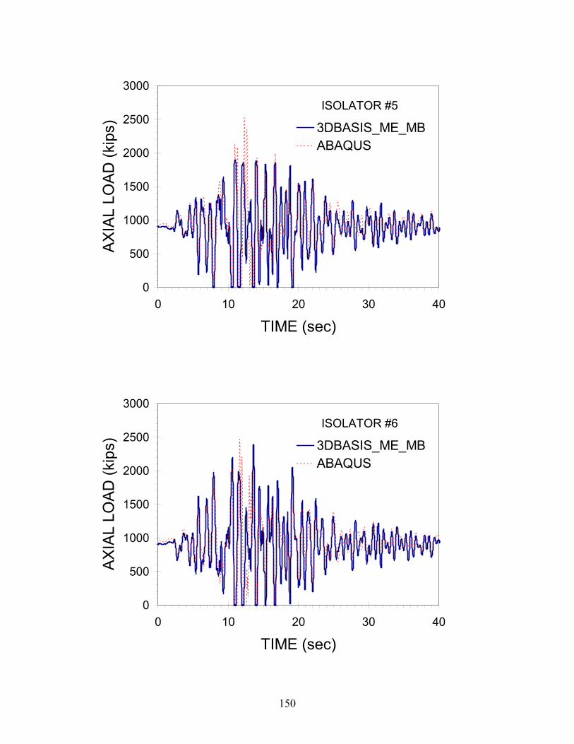
150
0
500
1000
1500
2000
2500
3000
0 10 20 30 40
TIME (sec)
AX
IAL
LOA
D (k
ips) 3DBASIS_ME_MB
ABAQUS
ISOLATOR #5
0
500
1000
1500
2000
2500
3000
0 10 20 30 40
TIME (sec)
AX
IAL
LOA
D (k
ips) 3DBASIS_ME_MB
ABAQUS
ISOLATOR #6

151
0
500
1000
1500
2000
2500
3000
3500
0 10 20 30 40
TIME (sec)
AX
IAL
LOA
D (k
ips)
3DBASIS_ME_MBABAQUS
ISOLATOR #7

152
-3
0
3
0 10 20 30 40
TIME (sec)
ISO
L. S
YS. D
ISPL
. (in
) 3DBASIS_ME_MBABAQUS
ISOLATION LEVEL BELOW 3-STORY TOWER on the LEFT
-900
0
900
-3 0 3DISPL. BELOW 3-STORY TOWER on the LEFT (in)
ISO
L. S
YS
. FO
RC
E (k
ips) 3DBASIS_ME_MB
ABAQUS
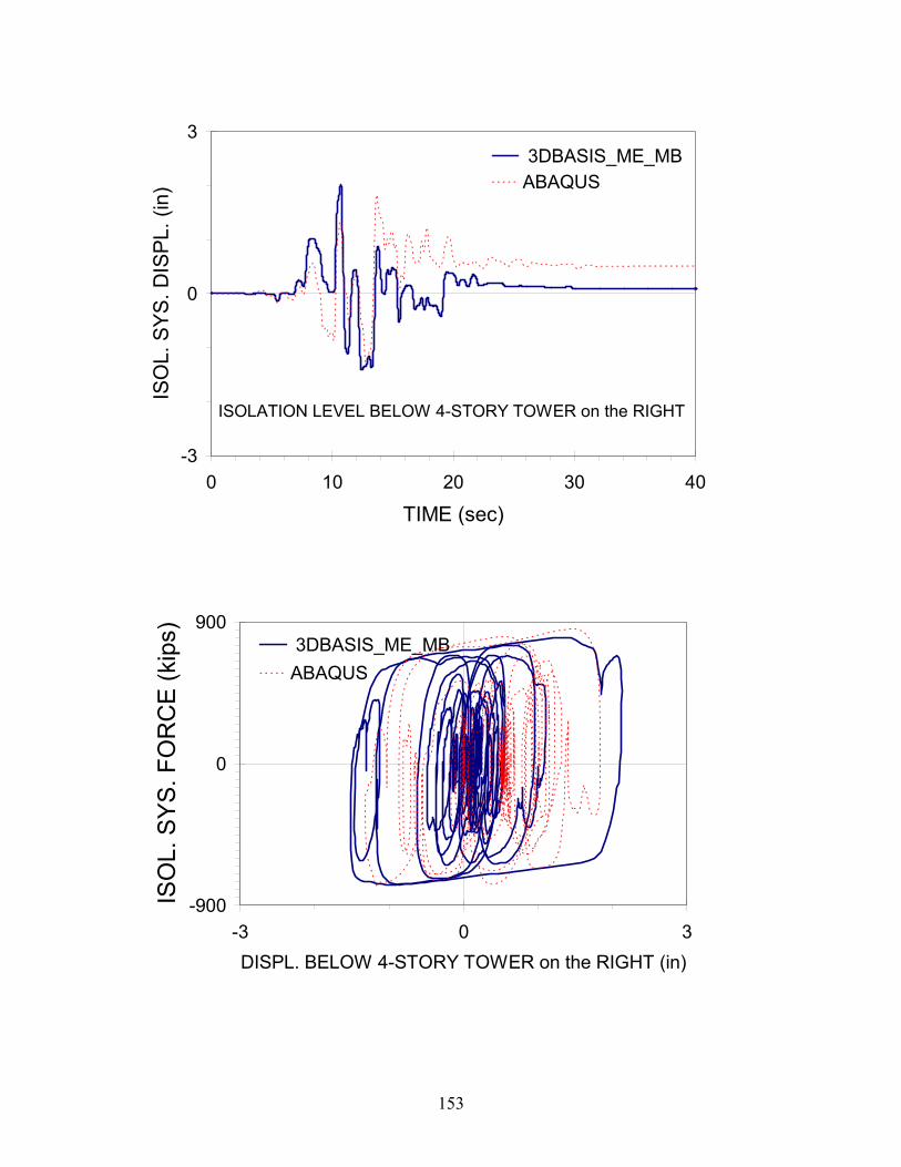
153
-3
0
3
0 10 20 30 40
TIME (sec)
ISO
L. S
YS. D
ISPL
. (in
) 3DBASIS_ME_MBABAQUS
ISOLATION LEVEL BELOW 4-STORY TOWER on the RIGHT
-900
0
900
-3 0 3DISPL. BELOW 4-STORY TOWER on the RIGHT (in)
ISO
L. S
YS
. FO
RC
E (k
ips) 3DBASIS_ME_MB
ABAQUS
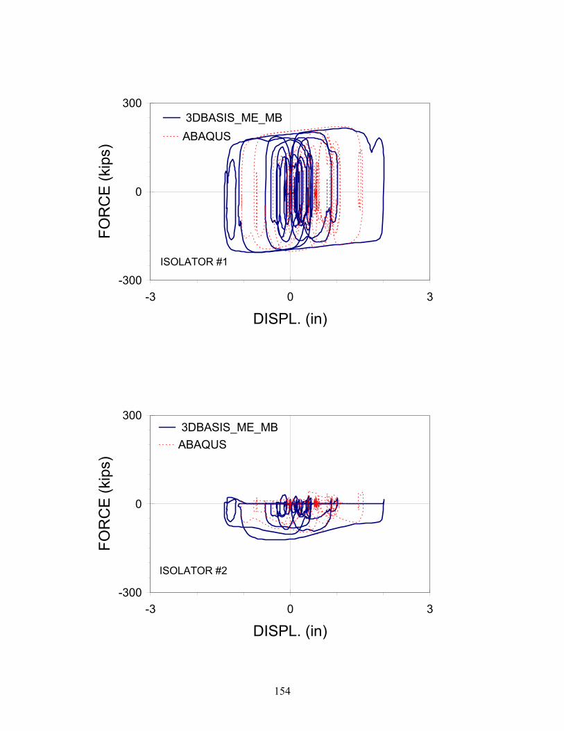
154
-300
0
300
-3 0 3
DISPL. (in)
FOR
CE
(kip
s) 3DBASIS_ME_MBABAQUS
ISOLATOR #1
-300
0
300
-3 0 3
DISPL. (in)
FOR
CE
(kip
s)
3DBASIS_ME_MBABAQUS
ISOLATOR #2

155
-300
0
300
-3 0 3
DISPL. (in)
FOR
CE
(kip
s) 3DBASIS_ME_MB
ABAQUS
ISOLATOR #3
-300
0
300
-3 0 3
DISPL. (in)
FOR
CE
(kip
s)
3DBASIS_ME_MBABAQUS
ISOLATOR #4
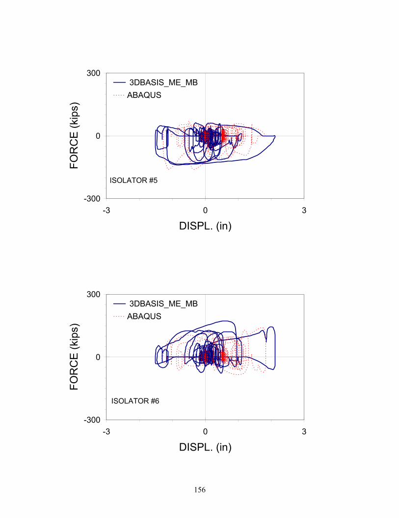
156
-300
0
300
-3 0 3
DISPL. (in)
FOR
CE
(kip
s) 3DBASIS_ME_MBABAQUS
ISOLATOR #5
-300
0
300
-3 0 3
DISPL. (in)
FOR
CE
(kip
s)
3DBASIS_ME_MBABAQUS
ISOLATOR #6
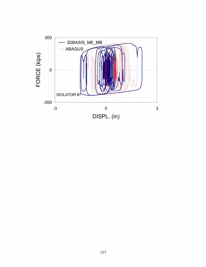
157
-300
0
300
-3 0 3
DISPL. (in)
FOR
CE
(kip
s) 3DBASIS_ME_MBABAQUS
ISOLATOR #7

158
-1
0
1
0 10 20 30 40TIME (sec)
DR
IFT
(in)
3DBASIS_ME_MBABAQUS
BOTTOM STORY of 3-STORY TOWER on the LEFT
-1
0
1
0 10 20 30 40TIME (sec)
DR
IFT
(in)
3DBASIS_ME_MBABAQUS
BOTTOM STORY of 4-STORY TOWER on the RIGHT

159
-0.5
0.0
0.5
0 10 20 30 40
TIME (secs)
AC
CE
LER
ATI
ON
(g)
3DBASIS_ME_MBABAQUS
TOP STORY of 3-STORY TOWER on the LEFT
-0.5
0.0
0.5
0 10 20 30 40
TIME (secs)
AC
CE
LER
ATI
ON
(g)
3DBASIS_ME_MBABAQUS
TOP STORY of 4-STORY TOWER on the RIGHT

160
-800
0
800
0 5 10 15 20 25 30 35 40TIME (sec)
BR
AC
E F
OR
CE
(kip
s)3D-BASISME_MBABAQUS
BOTTOM FLOOR 4-STORY TOWER on the RIGHT

161
APPENDIX K
COMPARISON OF RESULTS OF PROGRAM 3D-BASIS-ME-MB TO RESULTS
OF PROGRAM ABAQUS FOR TWO-TOWER VERIFICATION MODEL
(CASE OF FRICTION COEFFICIENT max 0.04f = )

162
-3
0
3
0 10 20 30 40
TIME (sec)
ISO
L. S
YS. D
ISPL
. (in
) 3DBASIS_ME_MBABAQUS
ISOLATION LEVEL BELOW 3-STORY TOWER on the LEFT
-900
0
900
-3 0 3DISPL. BELOW 3-STORY TOWER on the LEFT (in)
ISO
L. S
YS
. FO
RC
E (k
ips) 3DBASIS_ME_MB
ABAQUS
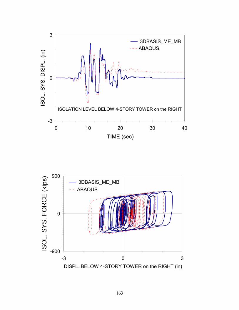
163
-3
0
3
0 10 20 30 40
TIME (sec)
ISO
L. S
YS. D
ISPL
. (in
) 3DBASIS_ME_MBABAQUS
ISOLATION LEVEL BELOW 4-STORY TOWER on the RIGHT
-900
0
900
-3 0 3DISPL. BELOW 4-STORY TOWER on the RIGHT (in)
ISO
L. S
YS
. FO
RC
E (k
ips) 3DBASIS_ME_MB
ABAQUS

164
-300
0
300
-3 0 3
DISPL. (in)
FOR
CE
(kip
s) 3DBASIS_ME_MBABAQUS
ISOLATOR #1
-300
0
300
-3 0 3
DISPL. (in)
FOR
CE
(kip
s)
3DBASIS_ME_MBABAQUS
ISOLATOR #2

165
-300
0
300
-3 0 3
DISPL. (in)
FOR
CE
(kip
s) 3DBASIS_ME_MB
ABAQUS
ISOLATOR #3
-300
0
300
-3 0 3
DISPL. (in)
FOR
CE
(kip
s)
3DBASIS_ME_MBABAQUS
ISOLATOR #4

166
-300
0
300
-3 0 3
DISPL. (in)
FOR
CE
(kip
s) 3DBASIS_ME_MBABAQUS
ISOLATOR #5
-300
0
300
-3 0 3
DISPL. (in)
FOR
CE
(kip
s)
3DBASIS_ME_MBABAQUS
ISOLATOR #6

167
-300
0
300
-3 0 3
DISPL. (in)
FOR
CE
(kip
s) 3DBASIS_ME_MBABAQUS
ISOLATOR #7

168
-0.5
0.0
0.5
0 10 20 30 40
TIME (secs)
AC
CE
LER
ATI
ON
(g)
3DBASIS_ME_MBABAQUS
TOP STORY of 3-STORY TOWER on the LEFT
-0.5
0.0
0.5
0 10 20 30 40
TIME (secs)
AC
CE
LER
ATI
ON
(g)
3DBASIS_ME_MBABAQUS
TOP STORY of 4-STORY TOWER on the RIGHT

169
-1
0
1
0 10 20 30 40TIME (sec)
DR
IFT
(in)
3DBASIS_ME_MBABAQUS
BOTTOM STORY of 3-STORY TOWER on the LEFT
-1
0
1
0 10 20 30 40TIME (sec)
DR
IFT
(in)
3DBASIS_ME_MBABAQUS
BOTTOM STORY of 4-STORY TOWER on the RIGHT

170
-800
0
800
0 5 10 15 20 25 30 35 40TIME (sec)
BR
AC
E F
OR
CE
(kip
s)3D-BASISME_MBABAQUS
BOTTOM FLOOR 4-STORY TOWER on the RIGHT

171
0
500
1000
1500
2000
2500
3000
3500
0 10 20 30 40
TIME (sec)
AX
IAL
LOA
D (k
ips)
3DBASIS_ME_MBABAQUS
ISOLATOR #1
0
500
1000
1500
2000
2500
3000
0 10 20 30 40
TIME (sec)
AX
IAL
LOA
D (k
ips) 3DBASIS_ME_MB
ABAQUS
ISOLATOR #2
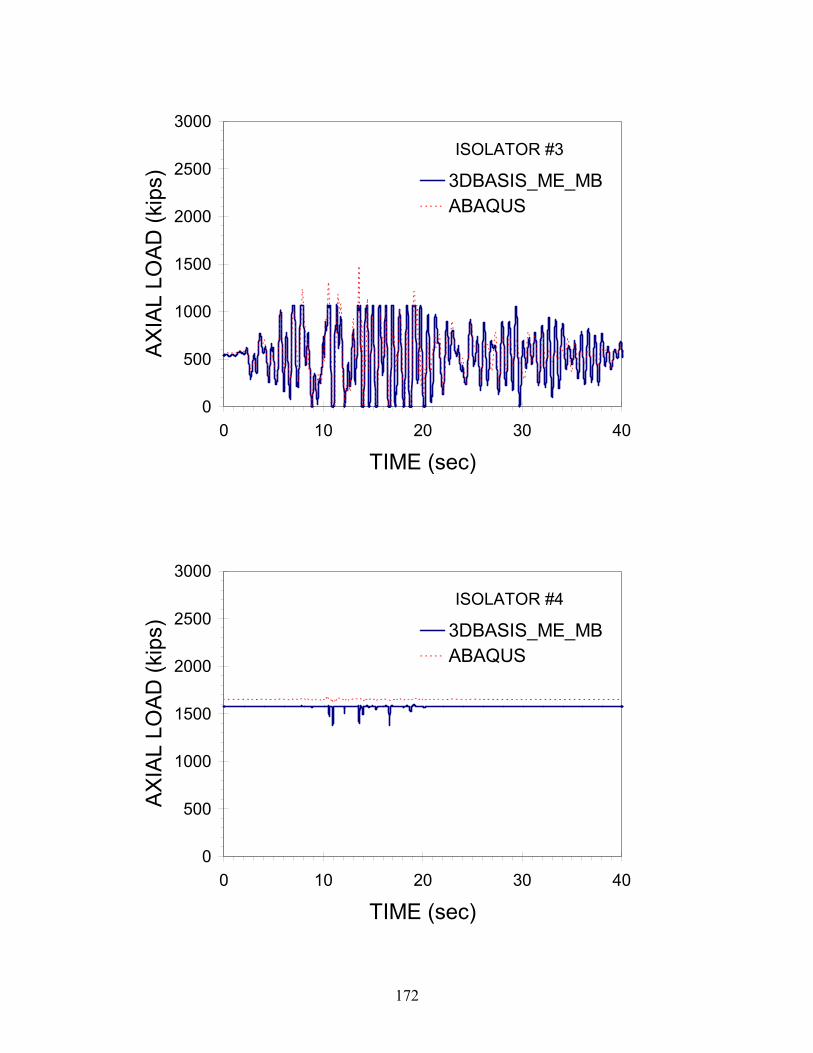
172
0
500
1000
1500
2000
2500
3000
0 10 20 30 40
TIME (sec)
AX
IAL
LOA
D (k
ips) 3DBASIS_ME_MB
ABAQUS
ISOLATOR #3
0
500
1000
1500
2000
2500
3000
0 10 20 30 40
TIME (sec)
AX
IAL
LOA
D (k
ips) 3DBASIS_ME_MB
ABAQUS
ISOLATOR #4

173
0
500
1000
1500
2000
2500
3000
0 10 20 30 40
TIME (sec)
AX
IAL
LOA
D (k
ips) 3DBASIS_ME_MB
ABAQUS
ISOLATOR #5
0
500
1000
1500
2000
2500
3000
0 10 20 30 40
TIME (sec)
AX
IAL
LOA
D (k
ips) 3DBASIS_ME_MB
ABAQUS
ISOLATOR #6

174
0
500
1000
1500
2000
2500
3000
3500
0 10 20 30 40
TIME (sec)
AX
IAL
LOA
D (k
ips)
3DBASIS_ME_MBABAQUS
ISOLATOR #7
Formerly the National Center for Earthquake Engineering Research
175
Multidisciplinary Center for Earthquake Engineering Research List of Technical Reports
The Multidisciplinary Center for Earthquake Engineering Research (MCEER) publishes technical reports on a variety of subjects related to earthquake engineering written by authors funded through MCEER. These reports are available from both MCEER Publications and the National Technical Information Service (NTIS). Requests for reports should be directed to MCEER Publications, Multidisciplinary Center for Earthquake Engineering Research, State University of New York at Buffalo, Red Jacket Quadrangle, Buffalo, New York 14261. Reports can also be requested through NTIS, 5285 Port Royal Road, Springfield, Virginia 22161. NTIS accession numbers are shown in parenthesis, if available. NCEER-87-0001 "First-Year Program in Research, Education and Technology Transfer," 3/5/87, (PB88-134275, A04, MF-
A01). NCEER-87-0002 "Experimental Evaluation of Instantaneous Optimal Algorithms for Structural Control," by R.C. Lin, T.T.
Soong and A.M. Reinhorn, 4/20/87, (PB88-134341, A04, MF-A01). NCEER-87-0003 "Experimentation Using the Earthquake Simulation Facilities at University at Buffalo," by A.M. Reinhorn
and R.L. Ketter, to be published. NCEER-87-0004 "The System Characteristics and Performance of a Shaking Table," by J.S. Hwang, K.C. Chang and G.C.
Lee, 6/1/87, (PB88-134259, A03, MF-A01). This report is available only through NTIS (see address given above).
NCEER-87-0005 "A Finite Element Formulation for Nonlinear Viscoplastic Material Using a Q Model," by O. Gyebi and G.
Dasgupta, 11/2/87, (PB88-213764, A08, MF-A01). NCEER-87-0006 "Symbolic Manipulation Program (SMP) - Algebraic Codes for Two and Three Dimensional Finite Element
Formulations," by X. Lee and G. Dasgupta, 11/9/87, (PB88-218522, A05, MF-A01). NCEER-87-0007 "Instantaneous Optimal Control Laws for Tall Buildings Under Seismic Excitations," by J.N. Yang, A.
Akbarpour and P. Ghaemmaghami, 6/10/87, (PB88-134333, A06, MF-A01). This report is only available through NTIS (see address given above).
NCEER-87-0008 "IDARC: Inelastic Damage Analysis of Reinforced Concrete Frame - Shear-Wall Structures," by Y.J. Park,
A.M. Reinhorn and S.K. Kunnath, 7/20/87, (PB88-134325, A09, MF-A01). This report is only available through NTIS (see address given above).
NCEER-87-0009 "Liquefaction Potential for New York State: A Preliminary Report on Sites in Manhattan and Buffalo," by
M. Budhu, V. Vijayakumar, R.F. Giese and L. Baumgras, 8/31/87, (PB88-163704, A03, MF-A01). This report is available only through NTIS (see address given above).
NCEER-87-0010 "Vertical and Torsional Vibration of Foundations in Inhomogeneous Media," by A.S. Veletsos and K.W.
Dotson, 6/1/87, (PB88-134291, A03, MF-A01). This report is only available through NTIS (see address given above).
NCEER-87-0011 "Seismic Probabilistic Risk Assessment and Seismic Margins Studies for Nuclear Power Plants," by Howard
H.M. Hwang, 6/15/87, (PB88-134267, A03, MF-A01). This report is only available through NTIS (see address given above).
NCEER-87-0012 "Parametric Studies of Frequency Response of Secondary Systems Under Ground-Acceleration Excitations,"
by Y. Yong and Y.K. Lin, 6/10/87, (PB88-134309, A03, MF-A01). This report is only available through NTIS (see address given above).
NCEER-87-0013 "Frequency Response of Secondary Systems Under Seismic Excitation," by J.A. HoLung, J. Cai and Y.K.
Lin, 7/31/87, (PB88-134317, A05, MF-A01). This report is only available through NTIS (see address given above).
NCEER-87-0014 "Modelling Earthquake Ground Motions in Seismically Active Regions Using Parametric Time Series
Methods," by G.W. Ellis and A.S. Cakmak, 8/25/87, (PB88-134283, A08, MF-A01). This report is only available through NTIS (see address given above).

Formerly the National Center for Earthquake Engineering Research
176
NCEER-87-0015 "Detection and Assessment of Seismic Structural Damage," by E. DiPasquale and A.S. Cakmak, 8/25/87,
(PB88-163712, A05, MF-A01). This report is only available through NTIS (see address given above). NCEER-87-0016 "Pipeline Experiment at Parkfield, California," by J. Isenberg and E. Richardson, 9/15/87, (PB88-163720,
A03, MF-A01). This report is available only through NTIS (see address given above). NCEER-87-0017 "Digital Simulation of Seismic Ground Motion," by M. Shinozuka, G. Deodatis and T. Harada, 8/31/87,
(PB88-155197, A04, MF-A01). This report is available only through NTIS (see address given above). NCEER-87-0018 "Practical Considerations for Structural Control: System Uncertainty, System Time Delay and Truncation of
Small Control Forces," J.N. Yang and A. Akbarpour, 8/10/87, (PB88-163738, A08, MF-A01). This report is only available through NTIS (see address given above).
NCEER-87-0019 "Modal Analysis of Nonclassically Damped Structural Systems Using Canonical Transformation," by J.N.
Yang, S. Sarkani and F.X. Long, 9/27/87, (PB88-187851, A04, MF-A01). NCEER-87-0020 "A Nonstationary Solution in Random Vibration Theory," by J.R. Red-Horse and P.D. Spanos, 11/3/87,
(PB88-163746, A03, MF-A01). NCEER-87-0021 "Horizontal Impedances for Radially Inhomogeneous Viscoelastic Soil Layers," by A.S. Veletsos and K.W.
Dotson, 10/15/87, (PB88-150859, A04, MF-A01). NCEER-87-0022 "Seismic Damage Assessment of Reinforced Concrete Members," by Y.S. Chung, C. Meyer and M.
Shinozuka, 10/9/87, (PB88-150867, A05, MF-A01). This report is available only through NTIS (see address given above).
NCEER-87-0023 "Active Structural Control in Civil Engineering," by T.T. Soong, 11/11/87, (PB88-187778, A03, MF-A01). NCEER-87-0024 "Vertical and Torsional Impedances for Radially Inhomogeneous Viscoelastic Soil Layers," by K.W. Dotson
and A.S. Veletsos, 12/87, (PB88-187786, A03, MF-A01). NCEER-87-0025 "Proceedings from the Symposium on Seismic Hazards, Ground Motions, Soil-Liquefaction and Engineering
Practice in Eastern North America," October 20-22, 1987, edited by K.H. Jacob, 12/87, (PB88-188115, A23, MF-A01). This report is available only through NTIS (see address given above).
NCEER-87-0026 "Report on the Whittier-Narrows, California, Earthquake of October 1, 1987," by J. Pantelic and A.
Reinhorn, 11/87, (PB88-187752, A03, MF-A01). This report is available only through NTIS (see address given above).
NCEER-87-0027 "Design of a Modular Program for Transient Nonlinear Analysis of Large 3-D Building Structures," by S.
Srivastav and J.F. Abel, 12/30/87, (PB88-187950, A05, MF-A01). This report is only available through NTIS (see address given above).
NCEER-87-0028 "Second-Year Program in Research, Education and Technology Transfer," 3/8/88, (PB88-219480, A04, MF-
A01). NCEER-88-0001 "Workshop on Seismic Computer Analysis and Design of Buildings With Interactive Graphics," by W.
McGuire, J.F. Abel and C.H. Conley, 1/18/88, (PB88-187760, A03, MF-A01). This report is only available through NTIS (see address given above).
NCEER-88-0002 "Optimal Control of Nonlinear Flexible Structures," by J.N. Yang, F.X. Long and D. Wong, 1/22/88, (PB88-
213772, A06, MF-A01). NCEER-88-0003 "Substructuring Techniques in the Time Domain for Primary-Secondary Structural Systems," by G.D.
Manolis and G. Juhn, 2/10/88, (PB88-213780, A04, MF-A01). NCEER-88-0004 "Iterative Seismic Analysis of Primary-Secondary Systems," by A. Singhal, L.D. Lutes and P.D. Spanos,
2/23/88, (PB88-213798, A04, MF-A01).
Formerly the National Center for Earthquake Engineering Research
177
NCEER-88-0005 "Stochastic Finite Element Expansion for Random Media," by P.D. Spanos and R. Ghanem, 3/14/88, (PB88-213806, A03, MF-A01).
NCEER-88-0006 "Combining Structural Optimization and Structural Control," by F.Y. Cheng and C.P. Pantelides, 1/10/88,
(PB88-213814, A05, MF-A01). NCEER-88-0007 "Seismic Performance Assessment of Code-Designed Structures," by H.H-M. Hwang, J-W. Jaw and H-J.
Shau, 3/20/88, (PB88-219423, A04, MF-A01). This report is only available through NTIS (see address given above).
NCEER-88-0008 "Reliability Analysis of Code-Designed Structures Under Natural Hazards," by H.H-M. Hwang, H. Ushiba
and M. Shinozuka, 2/29/88, (PB88-229471, A07, MF-A01). This report is only available through NTIS (see address given above).
NCEER-88-0009 "Seismic Fragility Analysis of Shear Wall Structures," by J-W Jaw and H.H-M. Hwang, 4/30/88, (PB89-
102867, A04, MF-A01). NCEER-88-0010 "Base Isolation of a Multi-Story Building Under a Harmonic Ground Motion - A Comparison of
Performances of Various Systems," by F-G Fan, G. Ahmadi and I.G. Tadjbakhsh, 5/18/88, (PB89-122238, A06, MF-A01). This report is only available through NTIS (see address given above).
NCEER-88-0011 "Seismic Floor Response Spectra for a Combined System by Green's Functions," by F.M. Lavelle, L.A.
Bergman and P.D. Spanos, 5/1/88, (PB89-102875, A03, MF-A01). NCEER-88-0012 "A New Solution Technique for Randomly Excited Hysteretic Structures," by G.Q. Cai and Y.K. Lin,
5/16/88, (PB89-102883, A03, MF-A01). NCEER-88-0013 "A Study of Radiation Damping and Soil-Structure Interaction Effects in the Centrifuge," by K. Weissman,
supervised by J.H. Prevost, 5/24/88, (PB89-144703, A06, MF-A01). NCEER-88-0014 "Parameter Identification and Implementation of a Kinematic Plasticity Model for Frictional Soils," by J.H.
Prevost and D.V. Griffiths, to be published. NCEER-88-0015 "Two- and Three- Dimensional Dynamic Finite Element Analyses of the Long Valley Dam," by D.V.
Griffiths and J.H. Prevost, 6/17/88, (PB89-144711, A04, MF-A01). NCEER-88-0016 "Damage Assessment of Reinforced Concrete Structures in Eastern United States," by A.M. Reinhorn, M.J.
Seidel, S.K. Kunnath and Y.J. Park, 6/15/88, (PB89-122220, A04, MF-A01). This report is only available through NTIS (see address given above).
NCEER-88-0017 "Dynamic Compliance of Vertically Loaded Strip Foundations in Multilayered Viscoelastic Soils," by S.
Ahmad and A.S.M. Israil, 6/17/88, (PB89-102891, A04, MF-A01). NCEER-88-0018 "An Experimental Study of Seismic Structural Response With Added Viscoelastic Dampers," by R.C. Lin, Z.
Liang, T.T. Soong and R.H. Zhang, 6/30/88, (PB89-122212, A05, MF-A01). This report is available only through NTIS (see address given above).
NCEER-88-0019 "Experimental Investigation of Primary - Secondary System Interaction," by G.D. Manolis, G. Juhn and
A.M. Reinhorn, 5/27/88, (PB89-122204, A04, MF-A01). NCEER-88-0020 "A Response Spectrum Approach For Analysis of Nonclassically Damped Structures," by J.N. Yang, S.
Sarkani and F.X. Long, 4/22/88, (PB89-102909, A04, MF-A01). NCEER-88-0021 "Seismic Interaction of Structures and Soils: Stochastic Approach," by A.S. Veletsos and A.M. Prasad,
7/21/88, (PB89-122196, A04, MF-A01). This report is only available through NTIS (see address given above).
NCEER-88-0022 "Identification of the Serviceability Limit State and Detection of Seismic Structural Damage," by E.
DiPasquale and A.S. Cakmak, 6/15/88, (PB89-122188, A05, MF-A01). This report is available only through NTIS (see address given above).

Formerly the National Center for Earthquake Engineering Research
178
NCEER-88-0023 "Multi-Hazard Risk Analysis: Case of a Simple Offshore Structure," by B.K. Bhartia and E.H. Vanmarcke, 7/21/88, (PB89-145213, A05, MF-A01).
NCEER-88-0024 "Automated Seismic Design of Reinforced Concrete Buildings," by Y.S. Chung, C. Meyer and M.
Shinozuka, 7/5/88, (PB89-122170, A06, MF-A01). This report is available only through NTIS (see address given above).
NCEER-88-0025 "Experimental Study of Active Control of MDOF Structures Under Seismic Excitations," by L.L. Chung,
R.C. Lin, T.T. Soong and A.M. Reinhorn, 7/10/88, (PB89-122600, A04, MF-A01). NCEER-88-0026 "Earthquake Simulation Tests of a Low-Rise Metal Structure," by J.S. Hwang, K.C. Chang, G.C. Lee and
R.L. Ketter, 8/1/88, (PB89-102917, A04, MF-A01). NCEER-88-0027 "Systems Study of Urban Response and Reconstruction Due to Catastrophic Earthquakes," by F. Kozin and
H.K. Zhou, 9/22/88, (PB90-162348, A04, MF-A01). NCEER-88-0028 "Seismic Fragility Analysis of Plane Frame Structures," by H.H-M. Hwang and Y.K. Low, 7/31/88, (PB89-
131445, A06, MF-A01). NCEER-88-0029 "Response Analysis of Stochastic Structures," by A. Kardara, C. Bucher and M. Shinozuka, 9/22/88, (PB89-
174429, A04, MF-A01). NCEER-88-0030 "Nonnormal Accelerations Due to Yielding in a Primary Structure," by D.C.K. Chen and L.D. Lutes,
9/19/88, (PB89-131437, A04, MF-A01). NCEER-88-0031 "Design Approaches for Soil-Structure Interaction," by A.S. Veletsos, A.M. Prasad and Y. Tang, 12/30/88,
(PB89-174437, A03, MF-A01). This report is available only through NTIS (see address given above). NCEER-88-0032 "A Re-evaluation of Design Spectra for Seismic Damage Control," by C.J. Turkstra and A.G. Tallin, 11/7/88,
(PB89-145221, A05, MF-A01). NCEER-88-0033 "The Behavior and Design of Noncontact Lap Splices Subjected to Repeated Inelastic Tensile Loading," by
V.E. Sagan, P. Gergely and R.N. White, 12/8/88, (PB89-163737, A08, MF-A01). NCEER-88-0034 "Seismic Response of Pile Foundations," by S.M. Mamoon, P.K. Banerjee and S. Ahmad, 11/1/88, (PB89-
145239, A04, MF-A01). NCEER-88-0035 "Modeling of R/C Building Structures With Flexible Floor Diaphragms (IDARC2)," by A.M. Reinhorn, S.K.
Kunnath and N. Panahshahi, 9/7/88, (PB89-207153, A07, MF-A01). NCEER-88-0036 "Solution of the Dam-Reservoir Interaction Problem Using a Combination of FEM, BEM with Particular
Integrals, Modal Analysis, and Substructuring," by C-S. Tsai, G.C. Lee and R.L. Ketter, 12/31/88, (PB89-207146, A04, MF-A01).
NCEER-88-0037 "Optimal Placement of Actuators for Structural Control," by F.Y. Cheng and C.P. Pantelides, 8/15/88,
(PB89-162846, A05, MF-A01). NCEER-88-0038 "Teflon Bearings in Aseismic Base Isolation: Experimental Studies and Mathematical Modeling," by A.
Mokha, M.C. Constantinou and A.M. Reinhorn, 12/5/88, (PB89-218457, A10, MF-A01). This report is available only through NTIS (see address given above).
NCEER-88-0039 "Seismic Behavior of Flat Slab High-Rise Buildings in the New York City Area," by P. Weidlinger and M.
Ettouney, 10/15/88, (PB90-145681, A04, MF-A01). NCEER-88-0040 "Evaluation of the Earthquake Resistance of Existing Buildings in New York City," by P. Weidlinger and M.
Ettouney, 10/15/88, to be published. NCEER-88-0041 "Small-Scale Modeling Techniques for Reinforced Concrete Structures Subjected to Seismic Loads," by W.
Kim, A. El-Attar and R.N. White, 11/22/88, (PB89-189625, A05, MF-A01).

Formerly the National Center for Earthquake Engineering Research
179
NCEER-88-0042 "Modeling Strong Ground Motion from Multiple Event Earthquakes," by G.W. Ellis and A.S. Cakmak, 10/15/88, (PB89-174445, A03, MF-A01).
NCEER-88-0043 "Nonstationary Models of Seismic Ground Acceleration," by M. Grigoriu, S.E. Ruiz and E. Rosenblueth,
7/15/88, (PB89-189617, A04, MF-A01). NCEER-88-0044 "SARCF User's Guide: Seismic Analysis of Reinforced Concrete Frames," by Y.S. Chung, C. Meyer and M.
Shinozuka, 11/9/88, (PB89-174452, A08, MF-A01). NCEER-88-0045 "First Expert Panel Meeting on Disaster Research and Planning," edited by J. Pantelic and J. Stoyle, 9/15/88,
(PB89-174460, A05, MF-A01). NCEER-88-0046 "Preliminary Studies of the Effect of Degrading Infill Walls on the Nonlinear Seismic Response of Steel
Frames," by C.Z. Chrysostomou, P. Gergely and J.F. Abel, 12/19/88, (PB89-208383, A05, MF-A01). NCEER-88-0047 "Reinforced Concrete Frame Component Testing Facility - Design, Construction, Instrumentation and
Operation," by S.P. Pessiki, C. Conley, T. Bond, P. Gergely and R.N. White, 12/16/88, (PB89-174478, A04, MF-A01).
NCEER-89-0001 "Effects of Protective Cushion and Soil Compliancy on the Response of Equipment Within a Seismically
Excited Building," by J.A. HoLung, 2/16/89, (PB89-207179, A04, MF-A01). NCEER-89-0002 "Statistical Evaluation of Response Modification Factors for Reinforced Concrete Structures," by H.H-M.
Hwang and J-W. Jaw, 2/17/89, (PB89-207187, A05, MF-A01). NCEER-89-0003 "Hysteretic Columns Under Random Excitation," by G-Q. Cai and Y.K. Lin, 1/9/89, (PB89-196513, A03,
MF-A01). NCEER-89-0004 "Experimental Study of `Elephant Foot Bulge' Instability of Thin-Walled Metal Tanks," by Z-H. Jia and R.L.
Ketter, 2/22/89, (PB89-207195, A03, MF-A01). NCEER-89-0005 "Experiment on Performance of Buried Pipelines Across San Andreas Fault," by J. Isenberg, E. Richardson
and T.D. O'Rourke, 3/10/89, (PB89-218440, A04, MF-A01). This report is available only through NTIS (see address given above).
NCEER-89-0006 "A Knowledge-Based Approach to Structural Design of Earthquake-Resistant Buildings," by M. Subramani,
P. Gergely, C.H. Conley, J.F. Abel and A.H. Zaghw, 1/15/89, (PB89-218465, A06, MF-A01). NCEER-89-0007 "Liquefaction Hazards and Their Effects on Buried Pipelines," by T.D. O'Rourke and P.A. Lane, 2/1/89,
(PB89-218481, A09, MF-A01). NCEER-89-0008 "Fundamentals of System Identification in Structural Dynamics," by H. Imai, C-B. Yun, O. Maruyama and
M. Shinozuka, 1/26/89, (PB89-207211, A04, MF-A01). NCEER-89-0009 "Effects of the 1985 Michoacan Earthquake on Water Systems and Other Buried Lifelines in Mexico," by
A.G. Ayala and M.J. O'Rourke, 3/8/89, (PB89-207229, A06, MF-A01). NCEER-89-R010 "NCEER Bibliography of Earthquake Education Materials," by K.E.K. Ross, Second Revision, 9/1/89,
(PB90-125352, A05, MF-A01). This report is replaced by NCEER-92-0018. NCEER-89-0011 "Inelastic Three-Dimensional Response Analysis of Reinforced Concrete Building Structures (IDARC-3D),
Part I - Modeling," by S.K. Kunnath and A.M. Reinhorn, 4/17/89, (PB90-114612, A07, MF-A01). This report is available only through NTIS (see address given above).
NCEER-89-0012 "Recommended Modifications to ATC-14," by C.D. Poland and J.O. Malley, 4/12/89, (PB90-108648, A15,
MF-A01). NCEER-89-0013 "Repair and Strengthening of Beam-to-Column Connections Subjected to Earthquake Loading," by M.
Corazao and A.J. Durrani, 2/28/89, (PB90-109885, A06, MF-A01).
Formerly the National Center for Earthquake Engineering Research
180
NCEER-89-0014 "Program EXKAL2 for Identification of Structural Dynamic Systems," by O. Maruyama, C-B. Yun, M. Hoshiya and M. Shinozuka, 5/19/89, (PB90-109877, A09, MF-A01).
NCEER-89-0015 "Response of Frames With Bolted Semi-Rigid Connections, Part I - Experimental Study and Analytical
Predictions," by P.J. DiCorso, A.M. Reinhorn, J.R. Dickerson, J.B. Radziminski and W.L. Harper, 6/1/89, to be published.
NCEER-89-0016 "ARMA Monte Carlo Simulation in Probabilistic Structural Analysis," by P.D. Spanos and M.P. Mignolet,
7/10/89, (PB90-109893, A03, MF-A01). NCEER-89-P017 "Preliminary Proceedings from the Conference on Disaster Preparedness - The Place of Earthquake
Education in Our Schools," Edited by K.E.K. Ross, 6/23/89, (PB90-108606, A03, MF-A01). NCEER-89-0017 "Proceedings from the Conference on Disaster Preparedness - The Place of Earthquake Education in Our
Schools," Edited by K.E.K. Ross, 12/31/89, (PB90-207895, A012, MF-A02). This report is available only through NTIS (see address given above).
NCEER-89-0018 "Multidimensional Models of Hysteretic Material Behavior for Vibration Analysis of Shape Memory Energy
Absorbing Devices, by E.J. Graesser and F.A. Cozzarelli, 6/7/89, (PB90-164146, A04, MF-A01). NCEER-89-0019 "Nonlinear Dynamic Analysis of Three-Dimensional Base Isolated Structures (3D-BASIS)," by S.
Nagarajaiah, A.M. Reinhorn and M.C. Constantinou, 8/3/89, (PB90-161936, A06, MF-A01). This report has been replaced by NCEER-93-0011.
NCEER-89-0020 "Structural Control Considering Time-Rate of Control Forces and Control Rate Constraints," by F.Y. Cheng
and C.P. Pantelides, 8/3/89, (PB90-120445, A04, MF-A01). NCEER-89-0021 "Subsurface Conditions of Memphis and Shelby County," by K.W. Ng, T-S. Chang and H-H.M. Hwang,
7/26/89, (PB90-120437, A03, MF-A01). NCEER-89-0022 "Seismic Wave Propagation Effects on Straight Jointed Buried Pipelines," by K. Elhmadi and M.J. O'Rourke,
8/24/89, (PB90-162322, A10, MF-A02). NCEER-89-0023 "Workshop on Serviceability Analysis of Water Delivery Systems," edited by M. Grigoriu, 3/6/89, (PB90-
127424, A03, MF-A01). NCEER-89-0024 "Shaking Table Study of a 1/5 Scale Steel Frame Composed of Tapered Members," by K.C. Chang, J.S.
Hwang and G.C. Lee, 9/18/89, (PB90-160169, A04, MF-A01). NCEER-89-0025 "DYNA1D: A Computer Program for Nonlinear Seismic Site Response Analysis - Technical
Documentation," by Jean H. Prevost, 9/14/89, (PB90-161944, A07, MF-A01). This report is available only through NTIS (see address given above).
NCEER-89-0026 "1:4 Scale Model Studies of Active Tendon Systems and Active Mass Dampers for Aseismic Protection," by
A.M. Reinhorn, T.T. Soong, R.C. Lin, Y.P. Yang, Y. Fukao, H. Abe and M. Nakai, 9/15/89, (PB90-173246, A10, MF-A02). This report is available only through NTIS (see address given above).
NCEER-89-0027 "Scattering of Waves by Inclusions in a Nonhomogeneous Elastic Half Space Solved by Boundary Element
Methods," by P.K. Hadley, A. Askar and A.S. Cakmak, 6/15/89, (PB90-145699, A07, MF-A01). NCEER-89-0028 "Statistical Evaluation of Deflection Amplification Factors for Reinforced Concrete Structures," by H.H.M.
Hwang, J-W. Jaw and A.L. Ch'ng, 8/31/89, (PB90-164633, A05, MF-A01). NCEER-89-0029 "Bedrock Accelerations in Memphis Area Due to Large New Madrid Earthquakes," by H.H.M. Hwang,
C.H.S. Chen and G. Yu, 11/7/89, (PB90-162330, A04, MF-A01). NCEER-89-0030 "Seismic Behavior and Response Sensitivity of Secondary Structural Systems," by Y.Q. Chen and T.T.
Soong, 10/23/89, (PB90-164658, A08, MF-A01). NCEER-89-0031 "Random Vibration and Reliability Analysis of Primary-Secondary Structural Systems," by Y. Ibrahim, M.
Grigoriu and T.T. Soong, 11/10/89, (PB90-161951, A04, MF-A01).

Formerly the National Center for Earthquake Engineering Research
181
NCEER-89-0032 "Proceedings from the Second U.S. - Japan Workshop on Liquefaction, Large Ground Deformation and
Their Effects on Lifelines, September 26-29, 1989," Edited by T.D. O'Rourke and M. Hamada, 12/1/89, (PB90-209388, A22, MF-A03).
NCEER-89-0033 "Deterministic Model for Seismic Damage Evaluation of Reinforced Concrete Structures," by J.M. Bracci,
A.M. Reinhorn, J.B. Mander and S.K. Kunnath, 9/27/89, (PB91-108803, A06, MF-A01). NCEER-89-0034 "On the Relation Between Local and Global Damage Indices," by E. DiPasquale and A.S. Cakmak, 8/15/89,
(PB90-173865, A05, MF-A01). NCEER-89-0035 "Cyclic Undrained Behavior of Nonplastic and Low Plasticity Silts," by A.J. Walker and H.E. Stewart,
7/26/89, (PB90-183518, A10, MF-A01). NCEER-89-0036 "Liquefaction Potential of Surficial Deposits in the City of Buffalo, New York," by M. Budhu, R. Giese and
L. Baumgrass, 1/17/89, (PB90-208455, A04, MF-A01). NCEER-89-0037 "A Deterministic Assessment of Effects of Ground Motion Incoherence," by A.S. Veletsos and Y. Tang,
7/15/89, (PB90-164294, A03, MF-A01). NCEER-89-0038 "Workshop on Ground Motion Parameters for Seismic Hazard Mapping," July 17-18, 1989, edited by R.V.
Whitman, 12/1/89, (PB90-173923, A04, MF-A01). NCEER-89-0039 "Seismic Effects on Elevated Transit Lines of the New York City Transit Authority," by C.J. Costantino,
C.A. Miller and E. Heymsfield, 12/26/89, (PB90-207887, A06, MF-A01). NCEER-89-0040 "Centrifugal Modeling of Dynamic Soil-Structure Interaction," by K. Weissman, Supervised by J.H. Prevost,
5/10/89, (PB90-207879, A07, MF-A01). NCEER-89-0041 "Linearized Identification of Buildings With Cores for Seismic Vulnerability Assessment," by I-K. Ho and
A.E. Aktan, 11/1/89, (PB90-251943, A07, MF-A01). NCEER-90-0001 "Geotechnical and Lifeline Aspects of the October 17, 1989 Loma Prieta Earthquake in San Francisco," by
T.D. O'Rourke, H.E. Stewart, F.T. Blackburn and T.S. Dickerman, 1/90, (PB90-208596, A05, MF-A01). NCEER-90-0002 "Nonnormal Secondary Response Due to Yielding in a Primary Structure," by D.C.K. Chen and L.D. Lutes,
2/28/90, (PB90-251976, A07, MF-A01). NCEER-90-0003 "Earthquake Education Materials for Grades K-12," by K.E.K. Ross, 4/16/90, (PB91-251984, A05, MF-
A05). This report has been replaced by NCEER-92-0018. NCEER-90-0004 "Catalog of Strong Motion Stations in Eastern North America," by R.W. Busby, 4/3/90, (PB90-251984, A05,
MF-A01). NCEER-90-0005 "NCEER Strong-Motion Data Base: A User Manual for the GeoBase Release (Version 1.0 for the Sun3)," by
P. Friberg and K. Jacob, 3/31/90 (PB90-258062, A04, MF-A01). NCEER-90-0006 "Seismic Hazard Along a Crude Oil Pipeline in the Event of an 1811-1812 Type New Madrid Earthquake,"
by H.H.M. Hwang and C-H.S. Chen, 4/16/90, (PB90-258054, A04, MF-A01). NCEER-90-0007 "Site-Specific Response Spectra for Memphis Sheahan Pumping Station," by H.H.M. Hwang and C.S. Lee,
5/15/90, (PB91-108811, A05, MF-A01). NCEER-90-0008 "Pilot Study on Seismic Vulnerability of Crude Oil Transmission Systems," by T. Ariman, R. Dobry, M.
Grigoriu, F. Kozin, M. O'Rourke, T. O'Rourke and M. Shinozuka, 5/25/90, (PB91-108837, A06, MF-A01). NCEER-90-0009 "A Program to Generate Site Dependent Time Histories: EQGEN," by G.W. Ellis, M. Srinivasan and A.S.
Cakmak, 1/30/90, (PB91-108829, A04, MF-A01). NCEER-90-0010 "Active Isolation for Seismic Protection of Operating Rooms," by M.E. Talbott, Supervised by M.
Shinozuka, 6/8/9, (PB91-110205, A05, MF-A01).

Formerly the National Center for Earthquake Engineering Research
182
NCEER-90-0011 "Program LINEARID for Identification of Linear Structural Dynamic Systems," by C-B. Yun and M.
Shinozuka, 6/25/90, (PB91-110312, A08, MF-A01). NCEER-90-0012 "Two-Dimensional Two-Phase Elasto-Plastic Seismic Response of Earth Dams," by A.N. Yiagos, Supervised
by J.H. Prevost, 6/20/90, (PB91-110197, A13, MF-A02). NCEER-90-0013 "Secondary Systems in Base-Isolated Structures: Experimental Investigation, Stochastic Response and
Stochastic Sensitivity," by G.D. Manolis, G. Juhn, M.C. Constantinou and A.M. Reinhorn, 7/1/90, (PB91-110320, A08, MF-A01).
NCEER-90-0014 "Seismic Behavior of Lightly-Reinforced Concrete Column and Beam-Column Joint Details," by S.P.
Pessiki, C.H. Conley, P. Gergely and R.N. White, 8/22/90, (PB91-108795, A11, MF-A02). NCEER-90-0015 "Two Hybrid Control Systems for Building Structures Under Strong Earthquakes," by J.N. Yang and A.
Danielians, 6/29/90, (PB91-125393, A04, MF-A01). NCEER-90-0016 "Instantaneous Optimal Control with Acceleration and Velocity Feedback," by J.N. Yang and Z. Li, 6/29/90,
(PB91-125401, A03, MF-A01). NCEER-90-0017 "Reconnaissance Report on the Northern Iran Earthquake of June 21, 1990," by M. Mehrain, 10/4/90, (PB91-
125377, A03, MF-A01). NCEER-90-0018 "Evaluation of Liquefaction Potential in Memphis and Shelby County," by T.S. Chang, P.S. Tang, C.S. Lee
and H. Hwang, 8/10/90, (PB91-125427, A09, MF-A01). NCEER-90-0019 "Experimental and Analytical Study of a Combined Sliding Disc Bearing and Helical Steel Spring Isolation
System," by M.C. Constantinou, A.S. Mokha and A.M. Reinhorn, 10/4/90, (PB91-125385, A06, MF-A01). This report is available only through NTIS (see address given above).
NCEER-90-0020 "Experimental Study and Analytical Prediction of Earthquake Response of a Sliding Isolation System with a
Spherical Surface," by A.S. Mokha, M.C. Constantinou and A.M. Reinhorn, 10/11/90, (PB91-125419, A05, MF-A01).
NCEER-90-0021 "Dynamic Interaction Factors for Floating Pile Groups," by G. Gazetas, K. Fan, A. Kaynia and E. Kausel,
9/10/90, (PB91-170381, A05, MF-A01). NCEER-90-0022 "Evaluation of Seismic Damage Indices for Reinforced Concrete Structures," by S. Rodriguez-Gomez and
A.S. Cakmak, 9/30/90, PB91-171322, A06, MF-A01). NCEER-90-0023 "Study of Site Response at a Selected Memphis Site," by H. Desai, S. Ahmad, E.S. Gazetas and M.R. Oh,
10/11/90, (PB91-196857, A03, MF-A01). NCEER-90-0024 "A User's Guide to Strongmo: Version 1.0 of NCEER's Strong-Motion Data Access Tool for PCs and
Terminals," by P.A. Friberg and C.A.T. Susch, 11/15/90, (PB91-171272, A03, MF-A01). NCEER-90-0025 "A Three-Dimensional Analytical Study of Spatial Variability of Seismic Ground Motions," by L-L. Hong
and A.H.-S. Ang, 10/30/90, (PB91-170399, A09, MF-A01). NCEER-90-0026 "MUMOID User's Guide - A Program for the Identification of Modal Parameters," by S. Rodriguez-Gomez
and E. DiPasquale, 9/30/90, (PB91-171298, A04, MF-A01). NCEER-90-0027 "SARCF-II User's Guide - Seismic Analysis of Reinforced Concrete Frames," by S. Rodriguez-Gomez, Y.S.
Chung and C. Meyer, 9/30/90, (PB91-171280, A05, MF-A01). NCEER-90-0028 "Viscous Dampers: Testing, Modeling and Application in Vibration and Seismic Isolation," by N. Makris
and M.C. Constantinou, 12/20/90 (PB91-190561, A06, MF-A01). NCEER-90-0029 "Soil Effects on Earthquake Ground Motions in the Memphis Area," by H. Hwang, C.S. Lee, K.W. Ng and
T.S. Chang, 8/2/90, (PB91-190751, A05, MF-A01).

Formerly the National Center for Earthquake Engineering Research
183
NCEER-91-0001 "Proceedings from the Third Japan-U.S. Workshop on Earthquake Resistant Design of Lifeline Facilities and Countermeasures for Soil Liquefaction, December 17-19, 1990," edited by T.D. O'Rourke and M. Hamada, 2/1/91, (PB91-179259, A99, MF-A04).
NCEER-91-0002 "Physical Space Solutions of Non-Proportionally Damped Systems," by M. Tong, Z. Liang and G.C. Lee,
1/15/91, (PB91-179242, A04, MF-A01). NCEER-91-0003 "Seismic Response of Single Piles and Pile Groups," by K. Fan and G. Gazetas, 1/10/91, (PB92-174994,
A04, MF-A01). NCEER-91-0004 "Damping of Structures: Part 1 - Theory of Complex Damping," by Z. Liang and G. Lee, 10/10/91, (PB92-
197235, A12, MF-A03). NCEER-91-0005 "3D-BASIS - Nonlinear Dynamic Analysis of Three Dimensional Base Isolated Structures: Part II," by S.
Nagarajaiah, A.M. Reinhorn and M.C. Constantinou, 2/28/91, (PB91-190553, A07, MF-A01). This report has been replaced by NCEER-93-0011.
NCEER-91-0006 "A Multidimensional Hysteretic Model for Plasticity Deforming Metals in Energy Absorbing Devices," by
E.J. Graesser and F.A. Cozzarelli, 4/9/91, (PB92-108364, A04, MF-A01). NCEER-91-0007 "A Framework for Customizable Knowledge-Based Expert Systems with an Application to a KBES for
Evaluating the Seismic Resistance of Existing Buildings," by E.G. Ibarra-Anaya and S.J. Fenves, 4/9/91, (PB91-210930, A08, MF-A01).
NCEER-91-0008 "Nonlinear Analysis of Steel Frames with Semi-Rigid Connections Using the Capacity Spectrum Method,"
by G.G. Deierlein, S-H. Hsieh, Y-J. Shen and J.F. Abel, 7/2/91, (PB92-113828, A05, MF-A01). NCEER-91-0009 "Earthquake Education Materials for Grades K-12," by K.E.K. Ross, 4/30/91, (PB91-212142, A06, MF-
A01). This report has been replaced by NCEER-92-0018. NCEER-91-0010 "Phase Wave Velocities and Displacement Phase Differences in a Harmonically Oscillating Pile," by N.
Makris and G. Gazetas, 7/8/91, (PB92-108356, A04, MF-A01). NCEER-91-0011 "Dynamic Characteristics of a Full-Size Five-Story Steel Structure and a 2/5 Scale Model," by K.C. Chang,
G.C. Yao, G.C. Lee, D.S. Hao and Y.C. Yeh," 7/2/91, (PB93-116648, A06, MF-A02). NCEER-91-0012 "Seismic Response of a 2/5 Scale Steel Structure with Added Viscoelastic Dampers," by K.C. Chang, T.T.
Soong, S-T. Oh and M.L. Lai, 5/17/91, (PB92-110816, A05, MF-A01). NCEER-91-0013 "Earthquake Response of Retaining Walls; Full-Scale Testing and Computational Modeling," by S.
Alampalli and A-W.M. Elgamal, 6/20/91, to be published. NCEER-91-0014 "3D-BASIS-M: Nonlinear Dynamic Analysis of Multiple Building Base Isolated Structures," by P.C.
Tsopelas, S. Nagarajaiah, M.C. Constantinou and A.M. Reinhorn, 5/28/91, (PB92-113885, A09, MF-A02). NCEER-91-0015 "Evaluation of SEAOC Design Requirements for Sliding Isolated Structures," by D. Theodossiou and M.C.
Constantinou, 6/10/91, (PB92-114602, A11, MF-A03). NCEER-91-0016 "Closed-Loop Modal Testing of a 27-Story Reinforced Concrete Flat Plate-Core Building," by H.R.
Somaprasad, T. Toksoy, H. Yoshiyuki and A.E. Aktan, 7/15/91, (PB92-129980, A07, MF-A02). NCEER-91-0017 "Shake Table Test of a 1/6 Scale Two-Story Lightly Reinforced Concrete Building," by A.G. El-Attar, R.N.
White and P. Gergely, 2/28/91, (PB92-222447, A06, MF-A02). NCEER-91-0018 "Shake Table Test of a 1/8 Scale Three-Story Lightly Reinforced Concrete Building," by A.G. El-Attar, R.N.
White and P. Gergely, 2/28/91, (PB93-116630, A08, MF-A02). NCEER-91-0019 "Transfer Functions for Rigid Rectangular Foundations," by A.S. Veletsos, A.M. Prasad and W.H. Wu,
7/31/91, to be published.

Formerly the National Center for Earthquake Engineering Research
184
NCEER-91-0020 "Hybrid Control of Seismic-Excited Nonlinear and Inelastic Structural Systems," by J.N. Yang, Z. Li and A. Danielians, 8/1/91, (PB92-143171, A06, MF-A02).
NCEER-91-0021 "The NCEER-91 Earthquake Catalog: Improved Intensity-Based Magnitudes and Recurrence Relations for
U.S. Earthquakes East of New Madrid," by L. Seeber and J.G. Armbruster, 8/28/91, (PB92-176742, A06, MF-A02).
NCEER-91-0022 "Proceedings from the Implementation of Earthquake Planning and Education in Schools: The Need for
Change - The Roles of the Changemakers," by K.E.K. Ross and F. Winslow, 7/23/91, (PB92-129998, A12, MF-A03).
NCEER-91-0023 "A Study of Reliability-Based Criteria for Seismic Design of Reinforced Concrete Frame Buildings," by
H.H.M. Hwang and H-M. Hsu, 8/10/91, (PB92-140235, A09, MF-A02). NCEER-91-0024 "Experimental Verification of a Number of Structural System Identification Algorithms," by R.G. Ghanem,
H. Gavin and M. Shinozuka, 9/18/91, (PB92-176577, A18, MF-A04). NCEER-91-0025 "Probabilistic Evaluation of Liquefaction Potential," by H.H.M. Hwang and C.S. Lee," 11/25/91, (PB92-
143429, A05, MF-A01). NCEER-91-0026 "Instantaneous Optimal Control for Linear, Nonlinear and Hysteretic Structures - Stable Controllers," by J.N.
Yang and Z. Li, 11/15/91, (PB92-163807, A04, MF-A01). NCEER-91-0027 "Experimental and Theoretical Study of a Sliding Isolation System for Bridges," by M.C. Constantinou, A.
Kartoum, A.M. Reinhorn and P. Bradford, 11/15/91, (PB92-176973, A10, MF-A03). NCEER-92-0001 "Case Studies of Liquefaction and Lifeline Performance During Past Earthquakes, Volume 1: Japanese Case
Studies," Edited by M. Hamada and T. O'Rourke, 2/17/92, (PB92-197243, A18, MF-A04). NCEER-92-0002 "Case Studies of Liquefaction and Lifeline Performance During Past Earthquakes, Volume 2: United States
Case Studies," Edited by T. O'Rourke and M. Hamada, 2/17/92, (PB92-197250, A20, MF-A04). NCEER-92-0003 "Issues in Earthquake Education," Edited by K. Ross, 2/3/92, (PB92-222389, A07, MF-A02). NCEER-92-0004 "Proceedings from the First U.S. - Japan Workshop on Earthquake Protective Systems for Bridges," Edited
by I.G. Buckle, 2/4/92, (PB94-142239, A99, MF-A06). NCEER-92-0005 "Seismic Ground Motion from a Haskell-Type Source in a Multiple-Layered Half-Space," A.P. Theoharis, G.
Deodatis and M. Shinozuka, 1/2/92, to be published. NCEER-92-0006 "Proceedings from the Site Effects Workshop," Edited by R. Whitman, 2/29/92, (PB92-197201, A04, MF-
A01). NCEER-92-0007 "Engineering Evaluation of Permanent Ground Deformations Due to Seismically-Induced Liquefaction," by
M.H. Baziar, R. Dobry and A-W.M. Elgamal, 3/24/92, (PB92-222421, A13, MF-A03). NCEER-92-0008 "A Procedure for the Seismic Evaluation of Buildings in the Central and Eastern United States," by C.D.
Poland and J.O. Malley, 4/2/92, (PB92-222439, A20, MF-A04). NCEER-92-0009 "Experimental and Analytical Study of a Hybrid Isolation System Using Friction Controllable Sliding
Bearings," by M.Q. Feng, S. Fujii and M. Shinozuka, 5/15/92, (PB93-150282, A06, MF-A02). NCEER-92-0010 "Seismic Resistance of Slab-Column Connections in Existing Non-Ductile Flat-Plate Buildings," by A.J.
Durrani and Y. Du, 5/18/92, (PB93-116812, A06, MF-A02). NCEER-92-0011 "The Hysteretic and Dynamic Behavior of Brick Masonry Walls Upgraded by Ferrocement Coatings Under
Cyclic Loading and Strong Simulated Ground Motion," by H. Lee and S.P. Prawel, 5/11/92, to be published. NCEER-92-0012 "Study of Wire Rope Systems for Seismic Protection of Equipment in Buildings," by G.F. Demetriades,
M.C. Constantinou and A.M. Reinhorn, 5/20/92, (PB93-116655, A08, MF-A02).

Formerly the National Center for Earthquake Engineering Research
185
NCEER-92-0013 "Shape Memory Structural Dampers: Material Properties, Design and Seismic Testing," by P.R. Witting and F.A. Cozzarelli, 5/26/92, (PB93-116663, A05, MF-A01).
NCEER-92-0014 "Longitudinal Permanent Ground Deformation Effects on Buried Continuous Pipelines," by M.J. O'Rourke,
and C. Nordberg, 6/15/92, (PB93-116671, A08, MF-A02). NCEER-92-0015 "A Simulation Method for Stationary Gaussian Random Functions Based on the Sampling Theorem," by M.
Grigoriu and S. Balopoulou, 6/11/92, (PB93-127496, A05, MF-A01). NCEER-92-0016 "Gravity-Load-Designed Reinforced Concrete Buildings: Seismic Evaluation of Existing Construction and
Detailing Strategies for Improved Seismic Resistance," by G.W. Hoffmann, S.K. Kunnath, A.M. Reinhorn and J.B. Mander, 7/15/92, (PB94-142007, A08, MF-A02).
NCEER-92-0017 "Observations on Water System and Pipeline Performance in the Limón Area of Costa Rica Due to the April
22, 1991 Earthquake," by M. O'Rourke and D. Ballantyne, 6/30/92, (PB93-126811, A06, MF-A02). NCEER-92-0018 "Fourth Edition of Earthquake Education Materials for Grades K-12," Edited by K.E.K. Ross, 8/10/92,
(PB93-114023, A07, MF-A02). NCEER-92-0019 "Proceedings from the Fourth Japan-U.S. Workshop on Earthquake Resistant Design of Lifeline Facilities
and Countermeasures for Soil Liquefaction," Edited by M. Hamada and T.D. O'Rourke, 8/12/92, (PB93-163939, A99, MF-E11).
NCEER-92-0020 "Active Bracing System: A Full Scale Implementation of Active Control," by A.M. Reinhorn, T.T. Soong,
R.C. Lin, M.A. Riley, Y.P. Wang, S. Aizawa and M. Higashino, 8/14/92, (PB93-127512, A06, MF-A02). NCEER-92-0021 "Empirical Analysis of Horizontal Ground Displacement Generated by Liquefaction-Induced Lateral
Spreads," by S.F. Bartlett and T.L. Youd, 8/17/92, (PB93-188241, A06, MF-A02). NCEER-92-0022 "IDARC Version 3.0: Inelastic Damage Analysis of Reinforced Concrete Structures," by S.K. Kunnath, A.M.
Reinhorn and R.F. Lobo, 8/31/92, (PB93-227502, A07, MF-A02). NCEER-92-0023 "A Semi-Empirical Analysis of Strong-Motion Peaks in Terms of Seismic Source, Propagation Path and
Local Site Conditions, by M. Kamiyama, M.J. O'Rourke and R. Flores-Berrones, 9/9/92, (PB93-150266, A08, MF-A02).
NCEER-92-0024 "Seismic Behavior of Reinforced Concrete Frame Structures with Nonductile Details, Part I: Summary of
Experimental Findings of Full Scale Beam-Column Joint Tests," by A. Beres, R.N. White and P. Gergely, 9/30/92, (PB93-227783, A05, MF-A01).
NCEER-92-0025 "Experimental Results of Repaired and Retrofitted Beam-Column Joint Tests in Lightly Reinforced Concrete
Frame Buildings," by A. Beres, S. El-Borgi, R.N. White and P. Gergely, 10/29/92, (PB93-227791, A05, MF-A01).
NCEER-92-0026 "A Generalization of Optimal Control Theory: Linear and Nonlinear Structures," by J.N. Yang, Z. Li and S.
Vongchavalitkul, 11/2/92, (PB93-188621, A05, MF-A01). NCEER-92-0027 "Seismic Resistance of Reinforced Concrete Frame Structures Designed Only for Gravity Loads: Part I -
Design and Properties of a One-Third Scale Model Structure," by J.M. Bracci, A.M. Reinhorn and J.B. Mander, 12/1/92, (PB94-104502, A08, MF-A02).
NCEER-92-0028 "Seismic Resistance of Reinforced Concrete Frame Structures Designed Only for Gravity Loads: Part II -
Experimental Performance of Subassemblages," by L.E. Aycardi, J.B. Mander and A.M. Reinhorn, 12/1/92, (PB94-104510, A08, MF-A02).
NCEER-92-0029 "Seismic Resistance of Reinforced Concrete Frame Structures Designed Only for Gravity Loads: Part III -
Experimental Performance and Analytical Study of a Structural Model," by J.M. Bracci, A.M. Reinhorn and J.B. Mander, 12/1/92, (PB93-227528, A09, MF-A01).

Formerly the National Center for Earthquake Engineering Research
186
NCEER-92-0030 "Evaluation of Seismic Retrofit of Reinforced Concrete Frame Structures: Part I - Experimental Performance of Retrofitted Subassemblages," by D. Choudhuri, J.B. Mander and A.M. Reinhorn, 12/8/92, (PB93-198307, A07, MF-A02).
NCEER-92-0031 "Evaluation of Seismic Retrofit of Reinforced Concrete Frame Structures: Part II - Experimental
Performance and Analytical Study of a Retrofitted Structural Model," by J.M. Bracci, A.M. Reinhorn and J.B. Mander, 12/8/92, (PB93-198315, A09, MF-A03).
NCEER-92-0032 "Experimental and Analytical Investigation of Seismic Response of Structures with Supplemental Fluid
Viscous Dampers," by M.C. Constantinou and M.D. Symans, 12/21/92, (PB93-191435, A10, MF-A03). This report is available only through NTIS (see address given above).
NCEER-92-0033 "Reconnaissance Report on the Cairo, Egypt Earthquake of October 12, 1992," by M. Khater, 12/23/92,
(PB93-188621, A03, MF-A01). NCEER-92-0034 "Low-Level Dynamic Characteristics of Four Tall Flat-Plate Buildings in New York City," by H. Gavin, S.
Yuan, J. Grossman, E. Pekelis and K. Jacob, 12/28/92, (PB93-188217, A07, MF-A02). NCEER-93-0001 "An Experimental Study on the Seismic Performance of Brick-Infilled Steel Frames With and Without
Retrofit," by J.B. Mander, B. Nair, K. Wojtkowski and J. Ma, 1/29/93, (PB93-227510, A07, MF-A02). NCEER-93-0002 "Social Accounting for Disaster Preparedness and Recovery Planning," by S. Cole, E. Pantoja and V. Razak,
2/22/93, (PB94-142114, A12, MF-A03). NCEER-93-0003 "Assessment of 1991 NEHRP Provisions for Nonstructural Components and Recommended Revisions," by
T.T. Soong, G. Chen, Z. Wu, R-H. Zhang and M. Grigoriu, 3/1/93, (PB93-188639, A06, MF-A02). NCEER-93-0004 "Evaluation of Static and Response Spectrum Analysis Procedures of SEAOC/UBC for Seismic Isolated
Structures," by C.W. Winters and M.C. Constantinou, 3/23/93, (PB93-198299, A10, MF-A03). NCEER-93-0005 "Earthquakes in the Northeast - Are We Ignoring the Hazard? A Workshop on Earthquake Science and
Safety for Educators," edited by K.E.K. Ross, 4/2/93, (PB94-103066, A09, MF-A02). NCEER-93-0006 "Inelastic Response of Reinforced Concrete Structures with Viscoelastic Braces," by R.F. Lobo, J.M. Bracci,
K.L. Shen, A.M. Reinhorn and T.T. Soong, 4/5/93, (PB93-227486, A05, MF-A02). NCEER-93-0007 "Seismic Testing of Installation Methods for Computers and Data Processing Equipment," by K. Kosar, T.T.
Soong, K.L. Shen, J.A. HoLung and Y.K. Lin, 4/12/93, (PB93-198299, A07, MF-A02). NCEER-93-0008 "Retrofit of Reinforced Concrete Frames Using Added Dampers," by A. Reinhorn, M. Constantinou and C.
Li, to be published. NCEER-93-0009 "Seismic Behavior and Design Guidelines for Steel Frame Structures with Added Viscoelastic Dampers," by
K.C. Chang, M.L. Lai, T.T. Soong, D.S. Hao and Y.C. Yeh, 5/1/93, (PB94-141959, A07, MF-A02). NCEER-93-0010 "Seismic Performance of Shear-Critical Reinforced Concrete Bridge Piers," by J.B. Mander, S.M. Waheed,
M.T.A. Chaudhary and S.S. Chen, 5/12/93, (PB93-227494, A08, MF-A02). NCEER-93-0011 "3D-BASIS-TABS: Computer Program for Nonlinear Dynamic Analysis of Three Dimensional Base Isolated
Structures," by S. Nagarajaiah, C. Li, A.M. Reinhorn and M.C. Constantinou, 8/2/93, (PB94-141819, A09, MF-A02).
NCEER-93-0012 "Effects of Hydrocarbon Spills from an Oil Pipeline Break on Ground Water," by O.J. Helweg and H.H.M.
Hwang, 8/3/93, (PB94-141942, A06, MF-A02). NCEER-93-0013 "Simplified Procedures for Seismic Design of Nonstructural Components and Assessment of Current Code
Provisions," by M.P. Singh, L.E. Suarez, E.E. Matheu and G.O. Maldonado, 8/4/93, (PB94-141827, A09, MF-A02).
NCEER-93-0014 "An Energy Approach to Seismic Analysis and Design of Secondary Systems," by G. Chen and T.T. Soong,
8/6/93, (PB94-142767, A11, MF-A03).
Formerly the National Center for Earthquake Engineering Research
187
NCEER-93-0015 "Proceedings from School Sites: Becoming Prepared for Earthquakes - Commemorating the Third
Anniversary of the Loma Prieta Earthquake," Edited by F.E. Winslow and K.E.K. Ross, 8/16/93, (PB94-154275, A16, MF-A02).
NCEER-93-0016 "Reconnaissance Report of Damage to Historic Monuments in Cairo, Egypt Following the October 12, 1992
Dahshur Earthquake," by D. Sykora, D. Look, G. Croci, E. Karaesmen and E. Karaesmen, 8/19/93, (PB94-142221, A08, MF-A02).
NCEER-93-0017 "The Island of Guam Earthquake of August 8, 1993," by S.W. Swan and S.K. Harris, 9/30/93, (PB94-
141843, A04, MF-A01). NCEER-93-0018 "Engineering Aspects of the October 12, 1992 Egyptian Earthquake," by A.W. Elgamal, M. Amer, K.
Adalier and A. Abul-Fadl, 10/7/93, (PB94-141983, A05, MF-A01). NCEER-93-0019 "Development of an Earthquake Motion Simulator and its Application in Dynamic Centrifuge Testing," by I.
Krstelj, Supervised by J.H. Prevost, 10/23/93, (PB94-181773, A-10, MF-A03). NCEER-93-0020 "NCEER-Taisei Corporation Research Program on Sliding Seismic Isolation Systems for Bridges:
Experimental and Analytical Study of a Friction Pendulum System (FPS)," by M.C. Constantinou, P. Tsopelas, Y-S. Kim and S. Okamoto, 11/1/93, (PB94-142775, A08, MF-A02).
NCEER-93-0021 "Finite Element Modeling of Elastomeric Seismic Isolation Bearings," by L.J. Billings, Supervised by R.
Shepherd, 11/8/93, to be published. NCEER-93-0022 "Seismic Vulnerability of Equipment in Critical Facilities: Life-Safety and Operational Consequences," by
K. Porter, G.S. Johnson, M.M. Zadeh, C. Scawthorn and S. Eder, 11/24/93, (PB94-181765, A16, MF-A03). NCEER-93-0023 "Hokkaido Nansei-oki, Japan Earthquake of July 12, 1993, by P.I. Yanev and C.R. Scawthorn, 12/23/93,
(PB94-181500, A07, MF-A01). NCEER-94-0001 "An Evaluation of Seismic Serviceability of Water Supply Networks with Application to the San Francisco
Auxiliary Water Supply System," by I. Markov, Supervised by M. Grigoriu and T. O'Rourke, 1/21/94, (PB94-204013, A07, MF-A02).
NCEER-94-0002 "NCEER-Taisei Corporation Research Program on Sliding Seismic Isolation Systems for Bridges:
Experimental and Analytical Study of Systems Consisting of Sliding Bearings, Rubber Restoring Force Devices and Fluid Dampers," Volumes I and II, by P. Tsopelas, S. Okamoto, M.C. Constantinou, D. Ozaki and S. Fujii, 2/4/94, (PB94-181740, A09, MF-A02 and PB94-181757, A12, MF-A03).
NCEER-94-0003 "A Markov Model for Local and Global Damage Indices in Seismic Analysis," by S. Rahman and M.
Grigoriu, 2/18/94, (PB94-206000, A12, MF-A03). NCEER-94-0004 "Proceedings from the NCEER Workshop on Seismic Response of Masonry Infills," edited by D.P. Abrams,
3/1/94, (PB94-180783, A07, MF-A02). NCEER-94-0005 "The Northridge, California Earthquake of January 17, 1994: General Reconnaissance Report," edited by
J.D. Goltz, 3/11/94, (PB94-193943, A10, MF-A03). NCEER-94-0006 "Seismic Energy Based Fatigue Damage Analysis of Bridge Columns: Part I - Evaluation of Seismic
Capacity," by G.A. Chang and J.B. Mander, 3/14/94, (PB94-219185, A11, MF-A03). NCEER-94-0007 "Seismic Isolation of Multi-Story Frame Structures Using Spherical Sliding Isolation Systems," by T.M. Al-
Hussaini, V.A. Zayas and M.C. Constantinou, 3/17/94, (PB94-193745, A09, MF-A02). NCEER-94-0008 "The Northridge, California Earthquake of January 17, 1994: Performance of Highway Bridges," edited by
I.G. Buckle, 3/24/94, (PB94-193851, A06, MF-A02). NCEER-94-0009 "Proceedings of the Third U.S.-Japan Workshop on Earthquake Protective Systems for Bridges," edited by
I.G. Buckle and I. Friedland, 3/31/94, (PB94-195815, A99, MF-A06).

Formerly the National Center for Earthquake Engineering Research
188
NCEER-94-0010 "3D-BASIS-ME: Computer Program for Nonlinear Dynamic Analysis of Seismically Isolated Single and Multiple Structures and Liquid Storage Tanks," by P.C. Tsopelas, M.C. Constantinou and A.M. Reinhorn, 4/12/94, (PB94-204922, A09, MF-A02).
NCEER-94-0011 "The Northridge, California Earthquake of January 17, 1994: Performance of Gas Transmission Pipelines,"
by T.D. O'Rourke and M.C. Palmer, 5/16/94, (PB94-204989, A05, MF-A01). NCEER-94-0012 "Feasibility Study of Replacement Procedures and Earthquake Performance Related to Gas Transmission
Pipelines," by T.D. O'Rourke and M.C. Palmer, 5/25/94, (PB94-206638, A09, MF-A02). NCEER-94-0013 "Seismic Energy Based Fatigue Damage Analysis of Bridge Columns: Part II - Evaluation of Seismic
Demand," by G.A. Chang and J.B. Mander, 6/1/94, (PB95-18106, A08, MF-A02). NCEER-94-0014 "NCEER-Taisei Corporation Research Program on Sliding Seismic Isolation Systems for Bridges:
Experimental and Analytical Study of a System Consisting of Sliding Bearings and Fluid Restoring Force/Damping Devices," by P. Tsopelas and M.C. Constantinou, 6/13/94, (PB94-219144, A10, MF-A03).
NCEER-94-0015 "Generation of Hazard-Consistent Fragility Curves for Seismic Loss Estimation Studies," by H. Hwang and
J-R. Huo, 6/14/94, (PB95-181996, A09, MF-A02). NCEER-94-0016 "Seismic Study of Building Frames with Added Energy-Absorbing Devices," by W.S. Pong, C.S. Tsai and
G.C. Lee, 6/20/94, (PB94-219136, A10, A03). NCEER-94-0017 "Sliding Mode Control for Seismic-Excited Linear and Nonlinear Civil Engineering Structures," by J. Yang,
J. Wu, A. Agrawal and Z. Li, 6/21/94, (PB95-138483, A06, MF-A02). NCEER-94-0018 "3D-BASIS-TABS Version 2.0: Computer Program for Nonlinear Dynamic Analysis of Three Dimensional
Base Isolated Structures," by A.M. Reinhorn, S. Nagarajaiah, M.C. Constantinou, P. Tsopelas and R. Li, 6/22/94, (PB95-182176, A08, MF-A02).
NCEER-94-0019 "Proceedings of the International Workshop on Civil Infrastructure Systems: Application of Intelligent
Systems and Advanced Materials on Bridge Systems," Edited by G.C. Lee and K.C. Chang, 7/18/94, (PB95-252474, A20, MF-A04).
NCEER-94-0020 "Study of Seismic Isolation Systems for Computer Floors," by V. Lambrou and M.C. Constantinou, 7/19/94,
(PB95-138533, A10, MF-A03). NCEER-94-0021 "Proceedings of the U.S.-Italian Workshop on Guidelines for Seismic Evaluation and Rehabilitation of
Unreinforced Masonry Buildings," Edited by D.P. Abrams and G.M. Calvi, 7/20/94, (PB95-138749, A13, MF-A03).
NCEER-94-0022 "NCEER-Taisei Corporation Research Program on Sliding Seismic Isolation Systems for Bridges:
Experimental and Analytical Study of a System Consisting of Lubricated PTFE Sliding Bearings and Mild Steel Dampers," by P. Tsopelas and M.C. Constantinou, 7/22/94, (PB95-182184, A08, MF-A02).
NCEER-94-0023 “Development of Reliability-Based Design Criteria for Buildings Under Seismic Load,” by Y.K. Wen, H.
Hwang and M. Shinozuka, 8/1/94, (PB95-211934, A08, MF-A02). NCEER-94-0024 “Experimental Verification of Acceleration Feedback Control Strategies for an Active Tendon System,” by
S.J. Dyke, B.F. Spencer, Jr., P. Quast, M.K. Sain, D.C. Kaspari, Jr. and T.T. Soong, 8/29/94, (PB95-212320, A05, MF-A01).
NCEER-94-0025 “Seismic Retrofitting Manual for Highway Bridges,” Edited by I.G. Buckle and I.F. Friedland, published by
the Federal Highway Administration (PB95-212676, A15, MF-A03). NCEER-94-0026 “Proceedings from the Fifth U.S.-Japan Workshop on Earthquake Resistant Design of Lifeline Facilities and
Countermeasures Against Soil Liquefaction,” Edited by T.D. O’Rourke and M. Hamada, 11/7/94, (PB95-220802, A99, MF-E08).

Formerly the National Center for Earthquake Engineering Research
189
NCEER-95-0001 “Experimental and Analytical Investigation of Seismic Retrofit of Structures with Supplemental Damping: Part 1 - Fluid Viscous Damping Devices,” by A.M. Reinhorn, C. Li and M.C. Constantinou, 1/3/95, (PB95-266599, A09, MF-A02).
NCEER-95-0002 “Experimental and Analytical Study of Low-Cycle Fatigue Behavior of Semi-Rigid Top-And-Seat Angle
Connections,” by G. Pekcan, J.B. Mander and S.S. Chen, 1/5/95, (PB95-220042, A07, MF-A02). NCEER-95-0003 “NCEER-ATC Joint Study on Fragility of Buildings,” by T. Anagnos, C. Rojahn and A.S. Kiremidjian,
1/20/95, (PB95-220026, A06, MF-A02). NCEER-95-0004 “Nonlinear Control Algorithms for Peak Response Reduction,” by Z. Wu, T.T. Soong, V. Gattulli and R.C.
Lin, 2/16/95, (PB95-220349, A05, MF-A01). NCEER-95-0005 “Pipeline Replacement Feasibility Study: A Methodology for Minimizing Seismic and Corrosion Risks to
Underground Natural Gas Pipelines,” by R.T. Eguchi, H.A. Seligson and D.G. Honegger, 3/2/95, (PB95-252326, A06, MF-A02).
NCEER-95-0006 “Evaluation of Seismic Performance of an 11-Story Frame Building During the 1994 Northridge
Earthquake,” by F. Naeim, R. DiSulio, K. Benuska, A. Reinhorn and C. Li, to be published. NCEER-95-0007 “Prioritization of Bridges for Seismic Retrofitting,” by N. Basöz and A.S. Kiremidjian, 4/24/95, (PB95-
252300, A08, MF-A02). NCEER-95-0008 “Method for Developing Motion Damage Relationships for Reinforced Concrete Frames,” by A. Singhal and
A.S. Kiremidjian, 5/11/95, (PB95-266607, A06, MF-A02). NCEER-95-0009 “Experimental and Analytical Investigation of Seismic Retrofit of Structures with Supplemental Damping:
Part II - Friction Devices,” by C. Li and A.M. Reinhorn, 7/6/95, (PB96-128087, A11, MF-A03). NCEER-95-0010 “Experimental Performance and Analytical Study of a Non-Ductile Reinforced Concrete Frame Structure
Retrofitted with Elastomeric Spring Dampers,” by G. Pekcan, J.B. Mander and S.S. Chen, 7/14/95, (PB96-137161, A08, MF-A02).
NCEER-95-0011 “Development and Experimental Study of Semi-Active Fluid Damping Devices for Seismic Protection of
Structures,” by M.D. Symans and M.C. Constantinou, 8/3/95, (PB96-136940, A23, MF-A04). NCEER-95-0012 “Real-Time Structural Parameter Modification (RSPM): Development of Innervated Structures,” by Z.
Liang, M. Tong and G.C. Lee, 4/11/95, (PB96-137153, A06, MF-A01). NCEER-95-0013 “Experimental and Analytical Investigation of Seismic Retrofit of Structures with Supplemental Damping:
Part III - Viscous Damping Walls,” by A.M. Reinhorn and C. Li, 10/1/95, (PB96-176409, A11, MF-A03). NCEER-95-0014 “Seismic Fragility Analysis of Equipment and Structures in a Memphis Electric Substation,” by J-R. Huo and
H.H.M. Hwang, 8/10/95, (PB96-128087, A09, MF-A02). NCEER-95-0015 “The Hanshin-Awaji Earthquake of January 17, 1995: Performance of Lifelines,” Edited by M. Shinozuka,
11/3/95, (PB96-176383, A15, MF-A03). NCEER-95-0016 “Highway Culvert Performance During Earthquakes,” by T.L. Youd and C.J. Beckman, available as
NCEER-96-0015. NCEER-95-0017 “The Hanshin-Awaji Earthquake of January 17, 1995: Performance of Highway Bridges,” Edited by I.G.
Buckle, 12/1/95, to be published. NCEER-95-0018 “Modeling of Masonry Infill Panels for Structural Analysis,” by A.M. Reinhorn, A. Madan, R.E. Valles, Y.
Reichmann and J.B. Mander, 12/8/95, (PB97-110886, MF-A01, A06). NCEER-95-0019 “Optimal Polynomial Control for Linear and Nonlinear Structures,” by A.K. Agrawal and J.N. Yang,
12/11/95, (PB96-168737, A07, MF-A02).

Formerly the National Center for Earthquake Engineering Research
190
NCEER-95-0020 “Retrofit of Non-Ductile Reinforced Concrete Frames Using Friction Dampers,” by R.S. Rao, P. Gergely and R.N. White, 12/22/95, (PB97-133508, A10, MF-A02).
NCEER-95-0021 “Parametric Results for Seismic Response of Pile-Supported Bridge Bents,” by G. Mylonakis, A. Nikolaou
and G. Gazetas, 12/22/95, (PB97-100242, A12, MF-A03). NCEER-95-0022 “Kinematic Bending Moments in Seismically Stressed Piles,” by A. Nikolaou, G. Mylonakis and G. Gazetas,
12/23/95, (PB97-113914, MF-A03, A13). NCEER-96-0001 “Dynamic Response of Unreinforced Masonry Buildings with Flexible Diaphragms,” by A.C. Costley and
D.P. Abrams,” 10/10/96, (PB97-133573, MF-A03, A15). NCEER-96-0002 “State of the Art Review: Foundations and Retaining Structures,” by I. Po Lam, to be published. NCEER-96-0003 “Ductility of Rectangular Reinforced Concrete Bridge Columns with Moderate Confinement,” by N. Wehbe,
M. Saiidi, D. Sanders and B. Douglas, 11/7/96, (PB97-133557, A06, MF-A02). NCEER-96-0004 “Proceedings of the Long-Span Bridge Seismic Research Workshop,” edited by I.G. Buckle and I.M.
Friedland, to be published. NCEER-96-0005 “Establish Representative Pier Types for Comprehensive Study: Eastern United States,” by J. Kulicki and Z.
Prucz, 5/28/96, (PB98-119217, A07, MF-A02). NCEER-96-0006 “Establish Representative Pier Types for Comprehensive Study: Western United States,” by R. Imbsen, R.A.
Schamber and T.A. Osterkamp, 5/28/96, (PB98-118607, A07, MF-A02). NCEER-96-0007 “Nonlinear Control Techniques for Dynamical Systems with Uncertain Parameters,” by R.G. Ghanem and
M.I. Bujakov, 5/27/96, (PB97-100259, A17, MF-A03). NCEER-96-0008 “Seismic Evaluation of a 30-Year Old Non-Ductile Highway Bridge Pier and Its Retrofit,” by J.B. Mander,
B. Mahmoodzadegan, S. Bhadra and S.S. Chen, 5/31/96, (PB97-110902, MF-A03, A10). NCEER-96-0009 “Seismic Performance of a Model Reinforced Concrete Bridge Pier Before and After Retrofit,” by J.B.
Mander, J.H. Kim and C.A. Ligozio, 5/31/96, (PB97-110910, MF-A02, A10). NCEER-96-0010 “IDARC2D Version 4.0: A Computer Program for the Inelastic Damage Analysis of Buildings,” by R.E.
Valles, A.M. Reinhorn, S.K. Kunnath, C. Li and A. Madan, 6/3/96, (PB97-100234, A17, MF-A03). NCEER-96-0011 “Estimation of the Economic Impact of Multiple Lifeline Disruption: Memphis Light, Gas and Water
Division Case Study,” by S.E. Chang, H.A. Seligson and R.T. Eguchi, 8/16/96, (PB97-133490, A11, MF-A03).
NCEER-96-0012 “Proceedings from the Sixth Japan-U.S. Workshop on Earthquake Resistant Design of Lifeline Facilities and
Countermeasures Against Soil Liquefaction, Edited by M. Hamada and T. O’Rourke, 9/11/96, (PB97-133581, A99, MF-A06).
NCEER-96-0013 “Chemical Hazards, Mitigation and Preparedness in Areas of High Seismic Risk: A Methodology for
Estimating the Risk of Post-Earthquake Hazardous Materials Release,” by H.A. Seligson, R.T. Eguchi, K.J. Tierney and K. Richmond, 11/7/96, (PB97-133565, MF-A02, A08).
NCEER-96-0014 “Response of Steel Bridge Bearings to Reversed Cyclic Loading,” by J.B. Mander, D-K. Kim, S.S. Chen and
G.J. Premus, 11/13/96, (PB97-140735, A12, MF-A03). NCEER-96-0015 “Highway Culvert Performance During Past Earthquakes,” by T.L. Youd and C.J. Beckman, 11/25/96,
(PB97-133532, A06, MF-A01). NCEER-97-0001 “Evaluation, Prevention and Mitigation of Pounding Effects in Building Structures,” by R.E. Valles and
A.M. Reinhorn, 2/20/97, (PB97-159552, A14, MF-A03). NCEER-97-0002 “Seismic Design Criteria for Bridges and Other Highway Structures,” by C. Rojahn, R. Mayes, D.G.
Anderson, J. Clark, J.H. Hom, R.V. Nutt and M.J. O’Rourke, 4/30/97, (PB97-194658, A06, MF-A03).

Formerly the National Center for Earthquake Engineering Research
191
NCEER-97-0003 “Proceedings of the U.S.-Italian Workshop on Seismic Evaluation and Retrofit,” Edited by D.P. Abrams and
G.M. Calvi, 3/19/97, (PB97-194666, A13, MF-A03). NCEER-97-0004 "Investigation of Seismic Response of Buildings with Linear and Nonlinear Fluid Viscous Dampers," by
A.A. Seleemah and M.C. Constantinou, 5/21/97, (PB98-109002, A15, MF-A03). NCEER-97-0005 "Proceedings of the Workshop on Earthquake Engineering Frontiers in Transportation Facilities," edited by
G.C. Lee and I.M. Friedland, 8/29/97, (PB98-128911, A25, MR-A04). NCEER-97-0006 "Cumulative Seismic Damage of Reinforced Concrete Bridge Piers," by S.K. Kunnath, A. El-Bahy, A.
Taylor and W. Stone, 9/2/97, (PB98-108814, A11, MF-A03). NCEER-97-0007 "Structural Details to Accommodate Seismic Movements of Highway Bridges and Retaining Walls," by R.A.
Imbsen, R.A. Schamber, E. Thorkildsen, A. Kartoum, B.T. Martin, T.N. Rosser and J.M. Kulicki, 9/3/97, (PB98-108996, A09, MF-A02).
NCEER-97-0008 "A Method for Earthquake Motion-Damage Relationships with Application to Reinforced Concrete Frames,"
by A. Singhal and A.S. Kiremidjian, 9/10/97, (PB98-108988, A13, MF-A03). NCEER-97-0009 "Seismic Analysis and Design of Bridge Abutments Considering Sliding and Rotation," by K. Fishman and
R. Richards, Jr., 9/15/97, (PB98-108897, A06, MF-A02). NCEER-97-0010 "Proceedings of the FHWA/NCEER Workshop on the National Representation of Seismic Ground Motion
for New and Existing Highway Facilities," edited by I.M. Friedland, M.S. Power and R.L. Mayes, 9/22/97, (PB98-128903, A21, MF-A04).
NCEER-97-0011 "Seismic Analysis for Design or Retrofit of Gravity Bridge Abutments," by K.L. Fishman, R. Richards, Jr.
and R.C. Divito, 10/2/97, (PB98-128937, A08, MF-A02). NCEER-97-0012 "Evaluation of Simplified Methods of Analysis for Yielding Structures," by P. Tsopelas, M.C. Constantinou,
C.A. Kircher and A.S. Whittaker, 10/31/97, (PB98-128929, A10, MF-A03). NCEER-97-0013 "Seismic Design of Bridge Columns Based on Control and Repairability of Damage," by C-T. Cheng and
J.B. Mander, 12/8/97, (PB98-144249, A11, MF-A03). NCEER-97-0014 "Seismic Resistance of Bridge Piers Based on Damage Avoidance Design," by J.B. Mander and C-T. Cheng,
12/10/97, (PB98-144223, A09, MF-A02). NCEER-97-0015 “Seismic Response of Nominally Symmetric Systems with Strength Uncertainty,” by S. Balopoulou and M.
Grigoriu, 12/23/97, (PB98-153422, A11, MF-A03). NCEER-97-0016 “Evaluation of Seismic Retrofit Methods for Reinforced Concrete Bridge Columns,” by T.J. Wipf, F.W.
Klaiber and F.M. Russo, 12/28/97, (PB98-144215, A12, MF-A03). NCEER-97-0017 “Seismic Fragility of Existing Conventional Reinforced Concrete Highway Bridges,” by C.L. Mullen and
A.S. Cakmak, 12/30/97, (PB98-153406, A08, MF-A02). NCEER-97-0018 “Loss Asssessment of Memphis Buildings,” edited by D.P. Abrams and M. Shinozuka, 12/31/97, (PB98-
144231, A13, MF-A03). NCEER-97-0019 “Seismic Evaluation of Frames with Infill Walls Using Quasi-static Experiments,” by K.M. Mosalam, R.N.
White and P. Gergely, 12/31/97, (PB98-153455, A07, MF-A02). NCEER-97-0020 “Seismic Evaluation of Frames with Infill Walls Using Pseudo-dynamic Experiments,” by K.M. Mosalam,
R.N. White and P. Gergely, 12/31/97, (PB98-153430, A07, MF-A02). NCEER-97-0021 “Computational Strategies for Frames with Infill Walls: Discrete and Smeared Crack Analyses and Seismic
Fragility,” by K.M. Mosalam, R.N. White and P. Gergely, 12/31/97, (PB98-153414, A10, MF-A02).
Formerly the National Center for Earthquake Engineering Research
192
NCEER-97-0022 “Proceedings of the NCEER Workshop on Evaluation of Liquefaction Resistance of Soils,” edited by T.L. Youd and I.M. Idriss, 12/31/97, (PB98-155617, A15, MF-A03).
MCEER-98-0001 “Extraction of Nonlinear Hysteretic Properties of Seismically Isolated Bridges from Quick-Release Field
Tests,” by Q. Chen, B.M. Douglas, E.M. Maragakis and I.G. Buckle, 5/26/98, (PB99-118838, A06, MF- A01).
MCEER-98-0002 “Methodologies for Evaluating the Importance of Highway Bridges,” by A. Thomas, S. Eshenaur and J.
Kulicki, 5/29/98, (PB99-118846, A10, MF-A02). MCEER-98-0003 “Capacity Design of Bridge Piers and the Analysis of Overstrength,” by J.B. Mander, A. Dutta and P. Goel,
6/1/98, (PB99-118853, A09, MF-A02). MCEER-98-0004 “Evaluation of Bridge Damage Data from the Loma Prieta and Northridge, California Earthquakes,” by N.
Basoz and A. Kiremidjian, 6/2/98, (PB99-118861, A15, MF-A03). MCEER-98-0005 “Screening Guide for Rapid Assessment of Liquefaction Hazard at Highway Bridge Sites,” by T. L. Youd,
6/16/98, (PB99-118879, A06, not available on microfiche). MCEER-98-0006 “Structural Steel and Steel/Concrete Interface Details for Bridges,” by P. Ritchie, N. Kauhl and J. Kulicki,
7/13/98, (PB99-118945, A06, MF-A01). MCEER-98-0007 “Capacity Design and Fatigue Analysis of Confined Concrete Columns,” by A. Dutta and J.B. Mander,
7/14/98, (PB99-118960, A14, MF-A03). MCEER-98-0008 “Proceedings of the Workshop on Performance Criteria for Telecommunication Services Under Earthquake
Conditions,” edited by A.J. Schiff, 7/15/98, (PB99-118952, A08, MF-A02). MCEER-98-0009 “Fatigue Analysis of Unconfined Concrete Columns,” by J.B. Mander, A. Dutta and J.H. Kim, 9/12/98,
(PB99-123655, A10, MF-A02). MCEER-98-0010 “Centrifuge Modeling of Cyclic Lateral Response of Pile-Cap Systems and Seat-Type Abutments in Dry
Sands,” by A.D. Gadre and R. Dobry, 10/2/98, (PB99-123606, A13, MF-A03). MCEER-98-0011 “IDARC-BRIDGE: A Computational Platform for Seismic Damage Assessment of Bridge Structures,” by
A.M. Reinhorn, V. Simeonov, G. Mylonakis and Y. Reichman, 10/2/98, (PB99-162919, A15, MF-A03). MCEER-98-0012 “Experimental Investigation of the Dynamic Response of Two Bridges Before and After Retrofitting with
Elastomeric Bearings,” by D.A. Wendichansky, S.S. Chen and J.B. Mander, 10/2/98, (PB99-162927, A15, MF-A03).
MCEER-98-0013 “Design Procedures for Hinge Restrainers and Hinge Sear Width for Multiple-Frame Bridges,” by R. Des
Roches and G.L. Fenves, 11/3/98, (PB99-140477, A13, MF-A03). MCEER-98-0014 “Response Modification Factors for Seismically Isolated Bridges,” by M.C. Constantinou and J.K. Quarshie,
11/3/98, (PB99-140485, A14, MF-A03). MCEER-98-0015 “Proceedings of the U.S.-Italy Workshop on Seismic Protective Systems for Bridges,” edited by I.M. Friedland
and M.C. Constantinou, 11/3/98, (PB2000-101711, A22, MF-A04). MCEER-98-0016 “Appropriate Seismic Reliability for Critical Equipment Systems: Recommendations Based on Regional
Analysis of Financial and Life Loss,” by K. Porter, C. Scawthorn, C. Taylor and N. Blais, 11/10/98, (PB99-157265, A08, MF-A02).
MCEER-98-0017 “Proceedings of the U.S. Japan Joint Seminar on Civil Infrastructure Systems Research,” edited by M.
Shinozuka and A. Rose, 11/12/98, (PB99-156713, A16, MF-A03). MCEER-98-0018 “Modeling of Pile Footings and Drilled Shafts for Seismic Design,” by I. PoLam, M. Kapuskar and D.
Chaudhuri, 12/21/98, (PB99-157257, A09, MF-A02).

Formerly the National Center for Earthquake Engineering Research
193
MCEER-99-0001 "Seismic Evaluation of a Masonry Infilled Reinforced Concrete Frame by Pseudodynamic Testing," by S.G. Buonopane and R.N. White, 2/16/99, (PB99-162851, A09, MF-A02).
MCEER-99-0002 "Response History Analysis of Structures with Seismic Isolation and Energy Dissipation Systems:
Verification Examples for Program SAP2000," by J. Scheller and M.C. Constantinou, 2/22/99, (PB99-162869, A08, MF-A02).
MCEER-99-0003 "Experimental Study on the Seismic Design and Retrofit of Bridge Columns Including Axial Load Effects,"
by A. Dutta, T. Kokorina and J.B. Mander, 2/22/99, (PB99-162877, A09, MF-A02). MCEER-99-0004 "Experimental Study of Bridge Elastomeric and Other Isolation and Energy Dissipation Systems with
Emphasis on Uplift Prevention and High Velocity Near-source Seismic Excitation," by A. Kasalanati and M. C. Constantinou, 2/26/99, (PB99-162885, A12, MF-A03).
MCEER-99-0005 "Truss Modeling of Reinforced Concrete Shear-flexure Behavior," by J.H. Kim and J.B. Mander, 3/8/99,
(PB99-163693, A12, MF-A03). MCEER-99-0006 "Experimental Investigation and Computational Modeling of Seismic Response of a 1:4 Scale Model Steel
Structure with a Load Balancing Supplemental Damping System," by G. Pekcan, J.B. Mander and S.S. Chen, 4/2/99, (PB99-162893, A11, MF-A03).
MCEER-99-0007 "Effect of Vertical Ground Motions on the Structural Response of Highway Bridges," by M.R. Button, C.J.
Cronin and R.L. Mayes, 4/10/99, (PB2000-101411, A10, MF-A03). MCEER-99-0008 "Seismic Reliability Assessment of Critical Facilities: A Handbook, Supporting Documentation, and Model
Code Provisions," by G.S. Johnson, R.E. Sheppard, M.D. Quilici, S.J. Eder and C.R. Scawthorn, 4/12/99, (PB2000-101701, A18, MF-A04).
MCEER-99-0009 "Impact Assessment of Selected MCEER Highway Project Research on the Seismic Design of Highway
Structures," by C. Rojahn, R. Mayes, D.G. Anderson, J.H. Clark, D'Appolonia Engineering, S. Gloyd and R.V. Nutt, 4/14/99, (PB99-162901, A10, MF-A02).
MCEER-99-0010 "Site Factors and Site Categories in Seismic Codes," by R. Dobry, R. Ramos and M.S. Power, 7/19/99,
(PB2000-101705, A08, MF-A02). MCEER-99-0011 "Restrainer Design Procedures for Multi-Span Simply-Supported Bridges," by M.J. Randall, M. Saiidi, E.
Maragakis and T. Isakovic, 7/20/99, (PB2000-101702, A10, MF-A02). MCEER-99-0012 "Property Modification Factors for Seismic Isolation Bearings," by M.C. Constantinou, P. Tsopelas, A.
Kasalanati and E. Wolff, 7/20/99, (PB2000-103387, A11, MF-A03). MCEER-99-0013 "Critical Seismic Issues for Existing Steel Bridges," by P. Ritchie, N. Kauhl and J. Kulicki, 7/20/99,
(PB2000-101697, A09, MF-A02). MCEER-99-0014 "Nonstructural Damage Database," by A. Kao, T.T. Soong and A. Vender, 7/24/99, (PB2000-101407, A06,
MF-A01). MCEER-99-0015 "Guide to Remedial Measures for Liquefaction Mitigation at Existing Highway Bridge Sites," by H.G.
Cooke and J. K. Mitchell, 7/26/99, (PB2000-101703, A11, MF-A03). MCEER-99-0016 "Proceedings of the MCEER Workshop on Ground Motion Methodologies for the Eastern United States,"
edited by N. Abrahamson and A. Becker, 8/11/99, (PB2000-103385, A07, MF-A02). MCEER-99-0017 "Quindío, Colombia Earthquake of January 25, 1999: Reconnaissance Report," by A.P. Asfura and P.J.
Flores, 10/4/99, (PB2000-106893, A06, MF-A01). MCEER-99-0018 "Hysteretic Models for Cyclic Behavior of Deteriorating Inelastic Structures," by M.V. Sivaselvan and A.M.
Reinhorn, 11/5/99, (PB2000-103386, A08, MF-A02).
Formerly the National Center for Earthquake Engineering Research
194
MCEER-99-0019 "Proceedings of the 7th U.S.- Japan Workshop on Earthquake Resistant Design of Lifeline Facilities and Countermeasures Against Soil Liquefaction," edited by T.D. O'Rourke, J.P. Bardet and M. Hamada, 11/19/99, (PB2000-103354, A99, MF-A06).
MCEER-99-0020 "Development of Measurement Capability for Micro-Vibration Evaluations with Application to Chip
Fabrication Facilities," by G.C. Lee, Z. Liang, J.W. Song, J.D. Shen and W.C. Liu, 12/1/99, (PB2000-105993, A08, MF-A02).
MCEER-99-0021 "Design and Retrofit Methodology for Building Structures with Supplemental Energy Dissipating Systems,"
by G. Pekcan, J.B. Mander and S.S. Chen, 12/31/99, (PB2000-105994, A11, MF-A03). MCEER-00-0001 "The Marmara, Turkey Earthquake of August 17, 1999: Reconnaissance Report," edited by C. Scawthorn;
with major contributions by M. Bruneau, R. Eguchi, T. Holzer, G. Johnson, J. Mander, J. Mitchell, W. Mitchell, A. Papageorgiou, C. Scaethorn, and G. Webb, 3/23/00, (PB2000-106200, A11, MF-A03).
MCEER-00-0002 "Proceedings of the MCEER Workshop for Seismic Hazard Mitigation of Health Care Facilities," edited by
G.C. Lee, M. Ettouney, M. Grigoriu, J. Hauer and J. Nigg, 3/29/00, (PB2000-106892, A08, MF-A02). MCEER-00-0003 "The Chi-Chi, Taiwan Earthquake of September 21, 1999: Reconnaissance Report," edited by G.C. Lee and
C.H. Loh, with major contributions by G.C. Lee, M. Bruneau, I.G. Buckle, S.E. Chang, P.J. Flores, T.D. O'Rourke, M. Shinozuka, T.T. Soong, C-H. Loh, K-C. Chang, Z-J. Chen, J-S. Hwang, M-L. Lin, G-Y. Liu, K-C. Tsai, G.C. Yao and C-L. Yen, 4/30/00, (PB2001-100980, A10, MF-A02).
MCEER-00-0004 "Seismic Retrofit of End-Sway Frames of Steel Deck-Truss Bridges with a Supplemental Tendon System:
Experimental and Analytical Investigation," by G. Pekcan, J.B. Mander and S.S. Chen, 7/1/00, (PB2001-100982, A10, MF-A02).
MCEER-00-0005 "Sliding Fragility of Unrestrained Equipment in Critical Facilities," by W.H. Chong and T.T. Soong, 7/5/00,
(PB2001-100983, A08, MF-A02). MCEER-00-0006 "Seismic Response of Reinforced Concrete Bridge Pier Walls in the Weak Direction," by N. Abo-Shadi, M.
Saiidi and D. Sanders, 7/17/00, (PB2001-100981, A17, MF-A03). MCEER-00-0007 "Low-Cycle Fatigue Behavior of Longitudinal Reinforcement in Reinforced Concrete Bridge Columns," by
J. Brown and S.K. Kunnath, 7/23/00, (PB2001-104392, A08, MF-A02). MCEER-00-0008 "Soil Structure Interaction of Bridges for Seismic Analysis," I. PoLam and H. Law, 9/25/00, (PB2001-
105397, A08, MF-A02). MCEER-00-0009 "Proceedings of the First MCEER Workshop on Mitigation of Earthquake Disaster by Advanced
Technologies (MEDAT-1), edited by M. Shinozuka, D.J. Inman and T.D. O'Rourke, 11/10/00, (PB2001-105399, A14, MF-A03).
MCEER-00-0010 "Development and Evaluation of Simplified Procedures for Analysis and Design of Buildings with Passive
Energy Dissipation Systems," by O.M. Ramirez, M.C. Constantinou, C.A. Kircher, A.S. Whittaker, M.W. Johnson, J.D. Gomez and C. Chrysostomou, 11/16/01, (PB2001-105523, A23, MF-A04).
MCEER-00-0011 "Dynamic Soil-Foundation-Structure Interaction Analyses of Large Caissons," by C-Y. Chang, C-M. Mok,
Z-L. Wang, R. Settgast, F. Waggoner, M.A. Ketchum, H.M. Gonnermann and C-C. Chin, 12/30/00, (PB2001-104373, A07, MF-A02).
MCEER-00-0012 "Experimental Evaluation of Seismic Performance of Bridge Restrainers," by A.G. Vlassis, E.M. Maragakis
and M. Saiid Saiidi, 12/30/00, (PB2001-104354, A09, MF-A02). MCEER-00-0013 "Effect of Spatial Variation of Ground Motion on Highway Structures," by M. Shinozuka, V. Saxena and G.
Deodatis, 12/31/00, (PB2001-108755, A13, MF-A03). MCEER-00-0014 "A Risk-Based Methodology for Assessing the Seismic Performance of Highway Systems," by S.D. Werner,
C.E. Taylor, J.E. Moore, II, J.S. Walton and S. Cho, 12/31/00, (PB2001-108756, A14, MF-A03).

Formerly the National Center for Earthquake Engineering Research
195
MCEER-01-0001 “Experimental Investigation of P-Delta Effects to Collapse During Earthquakes,” by D. Vian and M. Bruneau, 6/25/01, (PB2002-100534, A17, MF-A03).
MCEER-01-0002 “Proceedings of the Second MCEER Workshop on Mitigation of Earthquake Disaster by Advanced
Technologies (MEDAT-2),” edited by M. Bruneau and D.J. Inman, 7/23/01, (PB2002-100434, A16, MF-A03).
MCEER-01-0003 “Sensitivity Analysis of Dynamic Systems Subjected to Seismic Loads,” by C. Roth and M. Grigoriu,
9/18/01, (PB2003-100884, A12, MF-A03). MCEER-01-0004 “Overcoming Obstacles to Implementing Earthquake Hazard Mitigation Policies: Stage 1 Report,” by D.J.
Alesch and W.J. Petak, 12/17/01, (PB2002-107949, A07, MF-A02). MCEER-01-0005 “Updating Real-Time Earthquake Loss Estimates: Methods, Problems and Insights,” by C.E. Taylor, S.E.
Chang and R.T. Eguchi, 12/17/01, (PB2002-107948, A05, MF-A01). MCEER-01-0006 “Experimental Investigation and Retrofit of Steel Pile Foundations and Pile Bents Under Cyclic Lateral
Loadings,” by A. Shama, J. Mander, B. Blabac and S. Chen, 12/31/01, (PB2002-107950, A13, MF-A03). MCEER-02-0001 “Assessment of Performance of Bolu Viaduct in the 1999 Duzce Earthquake in Turkey” by P.C. Roussis,
M.C. Constantinou, M. Erdik, E. Durukal and M. Dicleli, 5/8/02, (PB2003-100883, A08, MF-A02). MCEER-02-0002 “Seismic Behavior of Rail Counterweight Systems of Elevators in Buildings,” by M.P. Singh, Rildova and
L.E. Suarez, 5/27/02. (PB2003-100882, A11, MF-A03). MCEER-02-0003 “Development of Analysis and Design Procedures for Spread Footings,” by G. Mylonakis, G. Gazetas, S.
Nikolaou and A. Chauncey, 10/02/02, (PB2004-101636, A13, MF-A03, CD-A13). MCEER-02-0004 “Bare-Earth Algorithms for Use with SAR and LIDAR Digital Elevation Models,” by C.K. Huyck, R.T.
Eguchi and B. Houshmand, 10/16/02, (PB2004-101637, A07, CD-A07). MCEER-02-0005 “Review of Energy Dissipation of Compression Members in Concentrically Braced Frames,” by K.Lee and
M. Bruneau, 10/18/02, (PB2004-101638, A10, CD-A10). MCEER-03-0001 “Experimental Investigation of Light-Gauge Steel Plate Shear Walls for the Seismic Retrofit of Buildings”
by J. Berman and M. Bruneau, 5/2/03, (PB2004-101622, A10, MF-A03, CD-A10).
MCEER-03-0002 “Statistical Analysis of Fragility Curves,” by M. Shinozuka, M.Q. Feng, H. Kim, T. Uzawa and T. Ueda, 6/16/03, (PB2004-101849, A09, CD-A09).
MCEER-03-0003 “Proceedings of the Eighth U.S.-Japan Workshop on Earthquake Resistant Design f Lifeline Facilities and
Countermeasures Against Liquefaction,” edited by M. Hamada, J.P. Bardet and T.D. O’Rourke, 6/30/03, (PB2004-104386, A99, CD-A99).
MCEER-03-0004 “Proceedings of the PRC-US Workshop on Seismic Analysis and Design of Special Bridges,” edited by L.C.
Fan and G.C. Lee, 7/15/03, (PB2004-104387, A14, CD-A14). MCEER-03-0005 “Urban Disaster Recovery: A Framework and Simulation Model,” by S.B. Miles and S.E. Chang, 7/25/03,
(PB2004-104388, A07, CD-A07). MCEER-03-0006 “Behavior of Underground Piping Joints Due to Static and Dynamic Loading,” by R.D. Meis, M. Maragakis
and R. Siddharthan, 11/17/03, (PB2005-102194, A13, MF-A03, CD-A00). MCEER-03-0007 “Seismic Vulnerability of Timber Bridges and Timber Substructures,” by A.A. Shama, J.B. Mander, I.M.
Friedland and D.R. Allicock, 12/15/03. MCEER-04-0001 “Experimental Study of Seismic Isolation Systems with Emphasis on Secondary System Response and
Verification of Accuracy of Dynamic Response History Analysis Methods,” by E. Wolff and M. Constantinou, 1/16/04 (PB2005-102195, A99, MF-E08, CD-A00).

Formerly the National Center for Earthquake Engineering Research
196
MCEER-04-0002 “Tension, Compression and Cyclic Testing of Engineered Cementitious Composite Materials,” by K. Kesner and S.L. Billington, 3/1/04, (PB2005-102196, A08, CD-A08).
MCEER-04-0003 “Cyclic Testing of Braces Laterally Restrained by Steel Studs to Enhance Performance During Earthquakes,”
by O.C. Celik, J.W. Berman and M. Bruneau, 3/16/04, (PB2005-102197, A13, MF-A03, CD-A00). MCEER-04-0004 “Methodologies for Post Earthquake Building Damage Detection Using SAR and Optical Remote Sensing:
Application to the August 17, 1999 Marmara, Turkey Earthquake,” by C.K. Huyck, B.J. Adams, S. Cho, R.T. Eguchi, B. Mansouri and B. Houshmand, 6/15/04, (PB2005-104888, A10, CD-A00).
MCEER-04-0005 “Nonlinear Structural Analysis Towards Collapse Simulation: A Dynamical Systems Approach,” by M.V.
Sivaselvan and A.M. Reinhorn, 6/16/04, (PB2005-104889, A11, MF-A03, CD-A00). MCEER-04-0006 “Proceedings of the Second PRC-US Workshop on Seismic Analysis and Design of Special Bridges,” edited
by G.C. Lee and L.C. Fan, 6/25/04, (PB2005-104890, A16, CD-A00). MCEER-04-0007 “Seismic Vulnerability Evaluation of Axially Loaded Steel Built-up Laced Members,” by K. Lee and M.
Bruneau, 6/30/04, (PB2005-104891, A16, CD-A00). MCEER-04-0008 “Evaluation of Accuracy of Simplified Methods of Analysis and Design of Buildings with Damping Systems
for Near-Fault and for Soft-Soil Seismic Motions,” by E.A. Pavlou and M.C. Constantinou, 8/16/04, (PB2005-104892, A08, MF-A02, CD-A00).
MCEER-04-0009 “Assessment of Geotechnical Issues in Acute Care Facilities in California,” by M. Lew, T.D. O’Rourke, R.
Dobry and M. Koch, 9/15/04, (PB2005-104893, A08, CD-A00). MCEER-04-0010 “Scissor-Jack-Damper Energy Dissipation System,” by A.N. Sigaher-Boyle and M.C. Constantinou, 12/1/04. MCEER-04-0011 “Seismic Retrofit of Bridge Steel Truss Piers Using a Controlled Rocking Approach,” by M. Pollino and M.
Bruneau, 12/20/04. MCEER-05-0001 “Experimental and Analytical Studies of Structures Seismically Isolated with an Uplift-Restraint Isolation
System,” by P.C. Roussis and M.C. Constantinou, 1/10/05. MCEER-05-0002 “A Versatile Experimentation Model for Study of Structures Near Collapse Applied to Seismic Evaluation of
Irregular Structures,” by D. Kusumastuti, A.M. Reinhorn and A. Rutenberg, 3/31/05. MCEER-05-0003 “Proceedings of the Third PRC-US Workshop on Seismic Analysis and Design of Special Bridges,” edited
by L.C. Fan and G.C. Lee, 4/20/05. MCEER-05-0004 “Approaches for the Seismic Retrofit of Braced Steel Bridge Piers and Proof-of-Concept Testing of an
Eccentrically Braced Frame with Tubular Link,” by J.W. Berman and M. Bruneau, 4/21/05. MCEER-05-0005 “Simulation of Strong Ground Motions for Seismic Fragility Evaluation of Nonstructural Components in
Hospitals,” by A. Wanitkorkul and A. Filiatrault, 5/26/05. MCEER-05-0006 “Seismic Safety in California Hospitals: Assessing an Attempt to Accelerate the Replacement or Seismic
Retrofit of Older Hospital Facilities,” by D.J. Alesch, L.A. Arendt and W.J. Petak, 6/6/05. MCEER-05-0007 “Development of Seismic Strengthening and Retrofit Strategies for Critical Facilities Using Engineered
Cementitious Composite Materials,” by K. Kesner and S.L. Billington, 8/29/05. MCEER-05-0008 “Experimental and Analytical Studies of Base Isolation Systems for Seismic Protection of Power
Transformers,” by N. Murota, M.Q. Feng and G-Y. Liu, 9/30/05. MCEER-05-0009 “3D-BASIS-ME-MB: Computer Program for Nonlinear Dynamic Analysis of Seismically Isolated
Structures,” by P.C. Tsopelas, P.C. Roussis, M.C. Constantinou, R. Buchanan and A.M. Reinhorn, 10/3/05.

University at Buffalo The State University of New York
University at Buffalo, State University of New York
Red Jacket Quadrangle ■ Buffalo, New York 14261
Phone: (716) 645-3391 ■ Fax: (716) 645-3399
E-mail: [email protected] ■ WWW Site http://mceer.buffalo.edu
ISSN 1520-295X