Embed Size (px)
Citation preview

3.9-1 Revision 3
V.C. Summer Nuclear Station, Units 2 and 3Updated Final Safety Analysis Report
3.9 Mechanical Systems and Components
3.9.1 Special Topics for Mechanical Components
3.9.1.1 Design Transients
To provide a high degree of integrity for the equipment in the reactor coolant system (RCS), components designed and constructed to the requirements for Class 1 in ASME Code, Section III are evaluated for design, service, and test conditions.
The design conditions include those pressure, temperature, and mechanical loadings selected as the basis for the design. Service conditions cover those normal operating conditions, anticipated transients, and postulated accident conditions expected or postulated to occur during operation. The evaluation of the service and testing conditions includes an evaluation of fatigue due to cyclic stresses.
The following five operating conditions, as defined in ASME Code, Section III, are considered in the design of the reactor coolant system Class 1 components, auxiliary Class 1 components, reactor coolant system component supports, and reactor internals.
Level A Service Conditions - (Normal Conditions) These conditions include any condition in the course of system startup, operation in the design power range, hot standby, and system shutdown other than Level B, Level C, or Level D service conditions or testing conditions. Tests not requiring a pressure greater than the component design pressure are considered to be normal condition design transients.
Level B Service Conditions - (Upset Conditions, Incidents of Moderate Frequency) These conditions include any deviations from Level A service conditions anticipated to occur often enough that the design includes a capability to withstand the conditions without operational impairment. The Level B service conditions include those transients resulting from any single operator error or control malfunction, transients caused by a fault in a system component requiring its isolation from the system, and transients due to loss of load or power. Level B service conditions include any abnormal incidents not resulting in a forced outage and also forced outages for which the corrective action does not include any repair of mechanical damage. The estimated duration of Level B service condition is included in the design specifications.
Level C Service Conditions - (Emergency Conditions, Infrequent Incidents) These conditions include those deviations from Level A service conditions that require shutdown for correction of the conditions or repair of damage in the system. The conditions have a low probability of occurrence but are included to establish that no gross loss of structural integrity will result as a concomitant effect of any damage developed in the system. The postulated occurrences for such events which result in more than 25 strong stress cycles are evaluated for cyclic fatigue using Level B service limits. Strong stress cycles are those having an alternating stress intensity value greater than that for 106 cycles from the applicable fatigue design curves.
Level D Service Conditions - (Faulted Conditions, Limiting Faults) These conditions include those combinations of conditions associated with extremely low-probability postulated events whose consequences are such that the integrity and operability of the nuclear energy system may be impaired to the extent that consideration of public health and safety is involved. Such considerations require compliance with safety criteria as may be specified by regulatory authorities.
Testing Conditions - Testing conditions are those pressure overload tests that include primary and secondary hydrostatic tests and steam generator tube leak tests specified. Other types of tests are classified under one of the other service condition categories.

3.9-2 Revision 3
V.C. Summer Nuclear Station, Units 2 and 3Updated Final Safety Analysis Report
In addition to the design transients defined for evaluation of the ASME Code, Section III, Class 1 components, other transients are defined to address the same normal operating conditions, anticipated transients, and postulated accident conditions. These alternate transients are developed for evaluations of other effects. For example, a set of transients is developed for equipment qualification (see Section 3.11) and a set for accident analysis (see Chapter 15). These transients have somewhat different assumptions for the number of transients and sequence of events than do the design transients.
To provide a high degree of integrity for the equipment in the reactor coolant system, the transient conditions selected for equipment fatigue evaluation are based upon a conservative estimate of the magnitude and frequency of the temperature and pressure transients that may occur during plant operation.
To a large extent, the specific transients to be considered for equipment fatigue analyses are based upon engineering judgment and experience. The plant condition (PC) categorization defined in ANS N51.1 (Reference 1), which categorizes transients on the basis of expected frequency, are also part of the process to define transients and which service condition applies for a given transient.
The transients selected are severe enough or frequent enough to be of possible significance to component cyclic behavior. The transients selected are a conservative representation of transients that, used as a basis for component fatigue evaluation, provide confidence that the component is appropriate for its application for the 60-year design objective. These transients are described by pertinent variations in pressure, fluid temperature, and fluid flow. Because of the large number of possible operating transients, design transients are chosen to provide a conservative representation for component cyclic analysis. The frequency in some cases is greater than the maximum frequency that defines the plant condition in ANS N51.1 (Reference 1).
The design transients and the number of events of each that are normally used for fatigue evaluations of components are presented in Table 3.9-1. A limited number of events affecting only the core makeup tank or passive residual heat removal heat exchanger are not included in the design transients. Subsections 5.4.13 and 5.4.14 describe these events.
The effects of each transient vary in consequence for each of the analyzed components. For example, the reactor vessel is subject to the pressure and temperature variations in the reactor coolant loop flow, but, the core makeup tank and passive residual heat removal heat exchangers are subject only to the pressure changes for many of the reactor coolant system transients. Additionally, the steam generator is subject to changes in the feedwater and steam system parameters that may have little or no effect on the other Class 1 components.
The individual component fatigue evaluations are based on component specific analyses of the stress levels and cycles of applied stress of the design transients. In many cases, the fatigue evaluations for the individual components combine two or more of the design transients into one bounding condition for that component.
In some cases the use of the total number of the design transients in a component fatigue analysis may indicate the requirement for a significant redesign of a portion of a component. In such cases, the number of one or more of the transients evaluated in the analysis may be reduced. In each case, the number of transients to be included in the analysis is specified in the component design specification.
In accordance with ASME Code, Section III, Level D service conditions and up to 25 stress cycles for Level C service conditions may be excluded from cyclic fatigue analysis. Any Level C service condition in excess of the 25-cycle limit is evaluated for the effect on cyclic fatigue, using Level B

*NRC Staff approval is required prior to implementing a change in this information.
3.9-3 Revision 3
V.C. Summer Nuclear Station, Units 2 and 3Updated Final Safety Analysis Report
criteria. The determination of which transients and seismic events are included in the 25-cycle exclusion is made separately for each component and piping line.
Levels C and D events are included in the design transients to provide the basis for pressure and temperatures used in the component stress analyses of these events. The number of events is given in the description of the transients and in Table 3.9-1 to support the determination that the fatigue evaluations do not have to consider these events.
[The stress analysis, including analysis of fatigue, of the piping, applicable component nozzles, and piping and component supports includes the effect of thermal stratification and thermal cycling.]* Thermal stratification may occur in piping when fluid rates are low and do not result in adequate mixing. Thermal cycling due to stratification may occur because of leaking valves or operational practices.
The design of piping and component nozzles in the AP1000 includes provisions to minimize the potential for and the effects of thermal stratification and cycling. [Piping and component supports are designed and evaluated for the thermal expansion of the piping resulting from potential stratification modes. The evaluation includes consideration of the information on thermal cycling and thermal stratification included in NRC Bulletins 88-08 and 88-11 and other applicable design standards.]*
The effects of earthquakes are not considered directly in the analyses leading to the fluid systems design transients. The presence or absence of seismic activity has no effect on the input data used for the analyses nor on the resulting pressure, temperature, and flow transients. Therefore, where applicable, in addition to the effects produced by the transients, earthquake loadings must be considered. See subsection 3.9.3 for a description of the seismic loads and other mechanical loads and loading combinations evaluated.
3.9.1.1.1 Level A Service Conditions (Normal Conditions)
The following reactor coolant system transients are considered normal operating transients (plant condition PC-1 per ANS N51.1) and are analyzed using Level A service limits:
Reactor coolant pump startup and shutdown Plant heatup and cooldown Unit loading and unloading between 0 and 15 percent of full power Unit loading and unloading at 5 percent of full power per minute Step load increase and decrease of 10 percent of full power Large step load decrease with steam dump Steady-state fluctuations and load regulation Boron concentration equalization Feedwater cycling Core lifetime extension Feedwater heaters out of service Refueling Turbine roll test Primary leakage test Secondary leakage test Core makeup tank high-pressure injection test Passive residual heat removal test Reactor coolant system makeup Daily load follow operations

3.9-4 Revision 3
V.C. Summer Nuclear Station, Units 2 and 3Updated Final Safety Analysis Report
3.9.1.1.1.1 Reactor Coolant Pump Startup and Shutdown
The reactor coolant pumps are started and stopped during such routine operations as plant heatup and cooldown and in connection with recovery from certain transients, such as loss of power. Other (undefined) circumstances may also require pump starting and stopping.
Of the spectrum of reactor coolant system pressure and temperature conditions under which these operations may occur, three conditions have been selected for defining transients:
Cold condition: 70°F and 400 psig - The minimum pressure required for reactor coolant pump operation may be as low as 100 psig. A pressure of 400 psig is considered a conservative value for design purposes.
Pump restart condition: 100°F and 400 psig - These conditions are included to cover situations requiring stopping and restarting the pumps after plant heatup has commenced.
Hot condition: 557°F and 2235 psig
These pressure and temperature values are defined for use in the design and fatigue evaluation processes. Actual pump starting and stopping conditions may be controlled by other factors such as reactor vessel material ductility considerations.
For reactor coolant pump starting and stopping operations, it is assumed that variations in reactor coolant system primary-side temperature and in-pressurizer pressure and temperature are negligible. Temperature and pressure changes in the steam generator secondary side are also assumed negligible. The only significant variables are the primary system flow and the pressure changes resulting from the pump operations.
The following cases are considered.
Case 1 - Pump Startup
Two startup cases are defined as described below.
One case represents the variations in reactor coolant loop flow at cold conditions, which accompany the simultaneous ramp up in speed of both reactor coolant pumps in one loop being driven from low speed to high speed. This case involves both the highest dynamic pressure loss and the largest change in dynamic pressure loss for cold conditions and, thus, conservatively represents the variations in reactor coolant flow accompanying operation of any single pump during cold conditions.
A case is also defined that represents the variations in reactor coolant loop flow at hot conditions, which accompany the startup of a second pump in the loop with a pump currently operating and both pumps in the other loop idle. This case involves both the highest dynamic pressure loss and the largest change in dynamic pressure loss and, thus, conservatively represents the variations in reactor coolant loop flow accompanying startup of any given single pump during hot conditions.
Case 2 - Pump Shutdown
This case represents the variations in reactor coolant loop flow, which accompany the shutdown of a pump when the only other operating pump is in the same loop. This transient is the reverse of the hot condition pump startup transient and involves an equally limiting change in dynamic pressure loss. It thus conservatively represents the variations in reactor coolant flow accompanying shutdown of any given single pump.

3.9-5 Revision 3
V.C. Summer Nuclear Station, Units 2 and 3Updated Final Safety Analysis Report
Design values for the pump starting/stopping conditions are given in Table 3.9-2 along with the assumed number of occurrences.
An example of the consequence of a pump startup is that the loop flow change associated with pump startup develops a pressure differential in the normal (forward) direction across the divider plate of the steam generator in that loop. In the loop undergoing reverse flow, the direction of the divider plate differential is reversed. The magnitude of the dynamic pressure drop depends on the volumetric flowrate through the loop and on the density and viscosity of the reactor coolant.
3.9.1.1.1.2 Plant Heatup and Cooldown
For the purpose of designing the major reactor coolant system components, the plant heatup and cooldown operations are conservatively represented by uniform ramp temperature changes of 100°F per hour when the system temperature is above 350°F. (For the pressurizer vessel, the design cooldown rate is 200°F per hour.) This rate bounds both potential nuclear heatup operations and cooldown using the steam dump system when system temperatures are greater than 350°F. Below 350°F, only reactor coolant pump heat and small amounts of decay heat are available to heat the reactor coolant system. Cooldown between 350°F and the shutdown temperature of 125°F is accomplished via the normal residual heat removal system. In this range, a uniform ramp rate of 50°F per hour is considered to bound the temperature changes resulting from these operations.
The number of plant heatup and cooldown operations is defined as 200 each, which corresponds to approximately three occurrences per year for design purposes.
3.9.1.1.1.3 Unit Loading and Unloading Between 0 and 15 Percent of Full Power
The unit loading and unloading cases between the 0 and 15 percent load are represented by continuous and uniform ramp steam load changes, which require 30 minutes for loading and five minutes for unloading. During loading, reactor coolant temperatures are changed from their no-load values to their normal load programmed temperature values at 15 percent load. The reverse temperature change occurs during unloading.
Before loading, it is assumed that the plant is at hot standby, with feedwater cycling from the main or startup feedwater system. Loading commences, and during the first two hours, the feedwater temperature increases to the 15 percent load value, because of steam dump and turbine startup heat input to the feedwater.
After unloading, feedwater heating is reduced, steam dump is reduced to residual heat removal requirements, and feedwater temperature decreases from the 15 percent load value. Reactor coolant system pressure and pressurizer pressure are assumed to remain constant at the normal operating values during these operations.
The number of these loading and unloading transients is assumed to be 500 each for design purposes.
3.9.1.1.1.4 Unit Loading and Unloading at Five Percent of Full Power per Minute
The unit loading and unloading operations are conservatively represented by continuous and uniform ramp power changes of 5 percent per minute between the 15 percent and 100 percent power levels. This load swing is the maximum possible that is consistent with operation under automatic reactor control. The reactor temperature will vary with load prescribed by the reactor control system.
The number of loading and unloading operations is defined as 2000 each for the 60-year plant design objective. The 2000 occurrences includes the plant loading and unloading for the normal plant

3.9-6 Revision 3
V.C. Summer Nuclear Station, Units 2 and 3Updated Final Safety Analysis Report
startup/shutdown, and loading resulting from all service levels B, C, and D transients that result in a reactor trip.
3.9.1.1.1.5 Step Load Increase and Decrease of 10 Percent of Full Power
The 10 percent step change in load demand results from disturbances in the electrical network to which the unit is tied. The reactor control system is designed to restore plant equilibrium without reactor trip following a 10 percent step change in turbine load demand initiated from nuclear plant equilibrium conditions between 15 and 100 percent of full load (the power range for automatic reactor control).
Following a step decrease in turbine load, the secondary-side steam pressure and temperature initially increase. The reactor coolant system average temperature and pressurizer pressure also increase, but this change lags slightly behind the secondary-side change. Because of the coolant temperature increase and the power mismatch between turbine and reactor, the control system automatically inserts the control rods to reduce core power. The reactor coolant temperature then decreases from its peak value to a value below its initial equilibrium value.
Pressurizer pressure also decreases from its peak value and follows the reactor coolant decreasing temperature trend. At some point during the decreasing pressure transient, the saturated water in the pressurizer begins to flash. This reduces the rate of pressure decrease. Subsequently, the pressurizer heaters turn on and restore the pressure to its normal value.
Following a step increase in turbine load, the reverse situation occurs. The secondary-side steam pressure and temperature initially decreases and the reactor coolant average temperature pressure initially decreases. The control system automatically withdraws the control rods to increase core power.
The decreasing pressure transient is reversed by actuation of the pressurizer heaters, and eventually the system pressure is restored to its normal value. The reactor coolant average temperature rises to a value above its initial equilibrium value.
The number of operations is specified as 3000 times each, or 50 times per year, for design purposes.
3.9.1.1.1.6 Large Step Load Decrease With Steam Dump
This transient applies to a step decrease in turbine load from full power. This step decrease in turbine load results in a rapid mismatch between nuclear and turbine power that automatically initiates a secondary-side steam dump and actuates the rapid power reduction system, which prevents both reactor trip and lifting of steam generator safety valves.
After the large step load decrease, reactor power is reduced at a controlled rate, which results in lower flow through the steam dump system.
The AP1000 plant is designed to accept a step load change to house load, without a reactor trip, with up to 40 percent of the load reduction provided by the steam dump capability. The balance of the load reduction is provided by the rapid power reduction system. The number of occurrences of this transient is specified at 200 times for design purposes.
3.9.1.1.1.7 Steady-State Fluctuations and Load Regulation
Reactor coolant pressure and temperature can vary around the nominal (steady-state) values during power operation. These variations can occur at many frequencies but for design purposes two cases are considered.

3.9-7 Revision 3
V.C. Summer Nuclear Station, Units 2 and 3Updated Final Safety Analysis Report
Initial Fluctuations - Initial fluctuations are due to rod cycling during the first 20 full power months of reactor operation. Reactor coolant temperature is assumed to vary by ± 3°F, and pressure by ± 25 psi once during each 2-minute period. The total number of occurrences is specified as 1.5 x 10⁵. The fluctuations are assumed to occur consecutively, but not simultaneously, with random fluctuations.
Random Fluctuations - Reactor coolant temperature is assumed to vary by ± 0.5°F, and pressure by ± six psi, once during each six-minute period. The total number of occurrences for design purposes does not exceed 4.6 x 10⁶.
These small, primary-side fluctuations have no effect on the steam generator secondary side.
The above described steady-state fluctuations and the following load regulation transients are considered to be mutually exclusive. Component evaluations are based on the more limiting of either the steady-state fluctuations or the load regulation transients.
Load Regulation - Load regulation refers to the relatively small, rapid fluctuations in load, regarding some nominal operating condition that is the result of the participation of the plant in some form of grid frequency control. The nominal operating condition is either a constant power level or a very slowly changing power level such as that which occurs because of a daily load follow maneuver.
For design purposes it is assumed that the plant experiences load changes of 10 percent of rated load peak-to-peak at a rate of 2 percent of rated load per minute. It is assumed that up to 35 of these load swings may occur during any given day of plant operation. Frequency control capability is to be provided while performing ramp power changes required for load follow maneuvers. This capability is to be provided within 15 to 95 percent of full power. Load regulation is performed with a continuous spray flow.
Assuming continuous operation of the plant in the load regulation mode for the 60-year design objective and accounting for 90 percent availability, the following component cycling limits will not be exceeded:
Control rod drive mechanism stepping ≤ 15 x 106 steps Pressurizer spray on-off cycling ≤ 750,000 Pressurizer backup heater on-off cycling ≤ 750,000
This cycling of the components should be considered to occur in addition to the duty cycles imposed on these components due to other modes of plant operation.
3.9.1.1.1.8 Boron Concentration Equalization
Following any large change in boron concentration in the reactor coolant system, the pressurizer spray is operated to equalize the concentration between the loops and the pressurizer. This can be done by manually operating the pressurizer backup heaters, which causes a pressure increase and spray initiation at a pressurizer pressure of approximately 2260 psia. The pressure increases to approximately 2267 psia before being returned to 2250 psia by the proportional spray. The pressure is maintained at 2250 psia by spray operation, matching the heat input from the backup heaters, until the concentration is equalized.
Since reactor coolant system boron concentration changes are not required for daily load follow, it is assumed that this operation is performed about once each week. For design purpose the total number of occurrences is placed at 2900.
The operations cause no significant effects on the steam generator secondary side. The only effects of these operations on the primary system are as follows:

3.9-8 Revision 3
V.C. Summer Nuclear Station, Units 2 and 3Updated Final Safety Analysis Report
The reactor coolant pressure varies in step with the pressurizer pressure.
The pressurizer surge line nozzle at the hot leg will experience the temperature transient associated with outflow from the pressurizer.
3.9.1.1.1.9 Feedwater Cycling
The feedwater cycling transient occurs when the plant is being maintained at hot standby or no-load condition. With the plant in the steam pressure mode of steam dump control, a low steam generation rate occurs because of dissipation of decay and/or pump heat. This low steam generation rate decreases steam generator water level.
To compensate for the decreasing level, the steam generators are fed using the startup feedwater control. Either the main or startup feedwater pumps can continuously provide flow to the steam generators and maintain the desired steam generator level. For this case the reactor coolant system transient is relatively moderate.
If the startup feedwater control system is unavailable, the feedwater is provided intermittently in a slug-feeding mode.
Two modes of slug-feeding the steam generators are considered. In the first mode, it is assumed that the steam generators are slug-fed through the startup feedwater nozzle once every two hours. In the second mode, it is assumed that tighter control of steam generator water level is maintained by slug-feeding once every 24 minutes.
For design purposes, the following numbers of feedwater cycling transients are considered:
Mode 1: Slug feed every 2 hours – 3000 cycles Mode 2: Slug feed every 24 minutes – 15,000 cycles
The component designers consider both modes of slug-feeding. Each component evaluation is based on the more limiting of the two modes.
3.9.1.1.1.10 Core Lifetime Extension
These transients occur at the end of core life when the critical boron concentration required to maintain full thermal power conditions becomes less than achievable (approximately 10 ppm). To extend core lifetime beyond this point, the operator does the following:
Allows the reactor coolant system average temperature to decrease below the normal programmed temperature, thereby adding reactivity to the core through the negative moderator temperature coefficient.
Manually controls the turbine to maintain full electrical load until the turbine control valves have fully opened.
Reduces steam flow by an amount that will maintain the plant at full rated electrical load after a feedwater heater has been taken out of service and allow plant conditions to reach a new steady state.
Takes a feedwater heater out of service.
This process is repeated until the maximum allowable feedwater heaters have been taken out of service and the turbine control valves have fully opened.

3.9-9 Revision 3
V.C. Summer Nuclear Station, Units 2 and 3Updated Final Safety Analysis Report
For design purposes, the number of occurrences of these transients is a total of 40 transients. During this mode of operation, the plant is not capable of daily load follow operation. Thus, this transient is considered separately from unit loading and unloading transients.
3.9.1.1.1.11 Feedwater Heaters Out of Service
These transients occur when one or more feedwater heaters are taken out of service. During the time that the heaters are out of service, the operator maintains the plant at full rated thermal load. To accomplish this, the operator performs the following:
Calculates the appropriate steam flow reduction which will maintain the plant at full rated thermal load after the heater has been taken out of service.
Reduces steam flow by the appropriate amount and allow plant conditions to reach a new steady state (approximately 10 minutes).
Takes heater (or heaters) out of service.
The transient is based on the maximum allowable number of heaters out of service. For design purposes, the number of occurrences of this transient is a total of 180.
3.9.1.1.1.12 Refueling
At the beginning of the refueling operation, the reactor coolant system is assumed to have been cooled down to 140°F. The vessel head is removed and the refueling canal is filled. This is done by transferring water from the in-containment refueling water storage tank, which is conservatively assumed to be at 70°F, into the reactor coolant system by means of the spent fuel pit cooling pumps. The refueling water flows directly into the reactor vessel via one of the passive safety injection system connections to the vessel.
This operation is assumed to occur 40 times over the expected plant design. This transient is experienced only by the primary system.
3.9.1.1.1.13 Turbine Roll Test
This transient is imposed upon the plant during the hot functional test for turbine cycle checkout. Reactor coolant pump power is used to heat the reactor coolant to operating temperature (no-load conditions), and the steam generator is used to perform a turbine roll test. However, the plant cooldown during this test exceeds the 100°F per hour design rate.
The number of such test cycles is specified at 20 times, to be performed at the beginning of plant operation before reactor operation. This transient occurs before plant startup, so the number of cycles is independent of other operating transients.
The transient curves and the number of cycles are based on a conservatively high steam flowrate for turning the turbine.
3.9.1.1.1.14 Primary-Side Leakage Test
A leakage test is performed after each opening of the primary system. During this test the primary system pressure is raised (for design purposes) to 2500 psia, with the system temperature above the minimum temperature imposed by reactor vessel material ductility requirements, while the system is checked for leaks.

3.9-10 Revision 3
V.C. Summer Nuclear Station, Units 2 and 3Updated Final Safety Analysis Report
The secondary side of the steam generator is pressurized so that the pressure differential across the tubesheet does not exceed 1600 psi. This is accomplished with the steam, feedwater, and blowdown lines closed.
For design purposes the number of occurrences is a total of 200 cycles.
3.9.1.1.1.15 Secondary-Side Leakage Test
A secondary side leakage test is performed after each opening of the secondary system to check closures for leakage. For design purposes, it is assumed that the steam generator secondary side is pressurized to just below its design pressure to prevent the safety valves from lifting. So that a secondary-side to primary-side pressure differential of 670 psi is not exceeded, the primary side must also be pressurized. The 670 psi differential is the steam generator design differential pressure for secondary-to-primary pressure. The primary system must be above the minimum temperature imposed by reactor vessel material ductility requirements (that is, between 120°F and 250°F). It is assumed that this test is performed 80 times for design purposes.
3.9.1.1.1.16 Core Makeup Tank High Pressure Injection Test
During hot functional testing with the reactor coolant system in hot standby condition, the core makeup tank injection flowrate is tested. The reactor coolant system temperature is 400°F. The core makeup tank injection lines are opened, and the core makeup tank injects cold water into the reactor coolant system. When valves are cycled during power, there is no effect on temperature or pressure.
3.9.1.1.1.17 Passive Residual Heat Removal Test
During hot functional testing with the reactor coolant system in hot standby condition, the passive residual heat removal flow and heat transfer rates are tested. Passive residual heat removal flow is initiated by opening the passive residual heat removal isolation valves. The passive residual heat removal cools the reactor coolant system for up to 30 minutes.
3.9.1.1.1.18 Reactor Coolant System Makeup
The chemical and volume control system makeup subsystem is used to accommodate normal minor leakage from the reactor coolant system. On a low programmed pressurizer level signal one of the chemical and volume control system makeup pumps starts automatically in order to provide makeup. The pump automatically stops when the pressurizer level increases to the high programmed setpoint. The addition of the makeup water to the reactor coolant system via the chemical and volume control system purification loop and attendant changes in reactor coolant system parameters constitute the reactor coolant system makeup design transient. The total number of occurrences of the makeup transient is 5640, which corresponds to twice per week during the plant design objective of 60 years assuming a 90 percent availability factor for the plant.
3.9.1.1.1.19 Daily Load Follow Operations
During the load follow operations, the plant power is reduced from the 100-percent power to 50-percent at a prescribed rate and remains there for a specified time, and then the power ramps up to 100-percent power at a prescribed rate. Power remains at 100-percent power for the remainder of the 24-hour cycle. The reactor coolant temperature will vary with load as prescribed by the reactor control systems.
The AP1000 features a rod control system that provides a load follow capability without requiring a change in the boron concentration in the coolant. Thus, the reactivity gain available from temperature
RN-12-033

3.9-11 Revision 3
V.C. Summer Nuclear Station, Units 2 and 3Updated Final Safety Analysis Report
reduction is not required for load follow, and reduced temperature return to power is not applicable to the AP1000.
The number of daily load follow operations is specified as 17,800 times during the plant design objective of 60 years. One swing of load follow operation consists of one power ramp down from steady-state 100-percent power to 50-percent power and one power ramp up from steady-state 50-percent power to 100-percent power.
3.9.1.1.2 Level B Service Conditions (Upset Conditions)
The following paragraphs describe the reactor coolant system upset condition transients, which are considered to be plant condition PC-2 and PC-3 per ANS N51.1. From the standpoint of the use of design transient in the evaluation of cyclic fatigue, there is no difference between PC-2 and PC-3. These transients are analyzed using Level B service limits and are as follows:
Loss of load
Loss of power
Reactor trip from reduced power
Reactor trip from full powerCase A - with no inadvertent cooldown
Case B - with cooldown and no safeguards actuation
Case C - with cooldown and safeguards actuation
Control rod drop - three cases
Cold overpressure
Inadvertent safeguards actuation - three cases
Partial loss of reactor coolant flow
Inadvertent reactor coolant system depressurization
Excessive feedwater flow
Loss of power with natural circulation cooldownCase A - loss of power with natural circulation cooldown with onsite ac powerCase B - loss of power with natural circulation cooldown without onsite ac power
Under the upset condition transients listed, 505 reactor trip cases are assumed. A total of 505 reactor trips for design purposes exceeds the design goal. The design goal for the AP1000 is less than one unplanned trip per year. The number of reactor trips in the design transients represents a conservative number for the analysis of cyclic stresses in the components and is not to be considered an estimate of expected plant performance.
For some component or portions of components, the number of reactor trips analyzed for the effects of cyclic loads may be reduced from 505. In each case the number of reactor trips analyzed is greater than the design goal of one per year.

3.9-12 Revision 3
V.C. Summer Nuclear Station, Units 2 and 3Updated Final Safety Analysis Report
3.9.1.1.2.1 Loss of Load
This transient involves a step decrease in turbine load from full power (turbine trip) without immediate automatic reactor trip or rapid power reduction. These conditions produce the most severe pressure transient on the reactor coolant system under upset conditions. The reactor is assumed to trip as a consequence of a trip initiated by the reactor protection system. Since redundant means for tripping the reactor are provided by the reactor protection system, a transient of this nature is not expected, but is included to confirm conservative component design.
The number of occurrences of this transient is specified at 30 times for design purposes.
3.9.1.1.2.2 Loss of Power
This transient applies to a blackout situation involving the loss of outside electrical power to the station, assumed to be operating initially at 102 percent power, followed by reactor and turbine trips. The reactor coolant pumps are de-energized, as are electrical loads connected to the turbine-generator bus, including the main feedwater and condensate pumps.
As the reactor coolant pumps coast down, reactor coolant system flow reaches an equilibrium value through natural circulation. This condition permits removal of core residual heat through the steam generators, which receive feedwater from the startup feedwater system. For this event reactor coolant temperature stabilizes at hot standby conditions.
The number of occurrences of this transient is specified at 30 times for design purposes.
For one occurrence, a worst case is postulated in which the shell side of a single steam generator is assumed to be emptied after the blackout. The startup feedwater flow is then delivered into the hot, dry shell side. The steam generator tube and secondary shell integrity are evaluated for this condition.
3.9.1.1.2.3 Reactor Trip from Reduced Power
A significant percentage of reactor trips occur at low power as the plant is being brought up from hot standby to power. The low power reactor trip is provided to bound these occurrences without the excessive conservatism associated with the reactor trip from full power. The transient is assumed to start at 25 percent load, which bounds the conditions associated with achieving criticality, turbine roll, and turbine synchronization; establishing automatic rod control; and making the transitions in feedwater control from the startup feedwater nozzle to the main feedwater nozzle.
Reactor coolant system temperature and pressure variations are similar to those of reactor trip from full power, but are smaller. The transients continue until the reactor coolant and steam generator secondary side temperatures are in equilibrium at zero power conditions. Controlled steam dump and startup feedwater remove any core residual heat and prevent steam generator safety valve actuation. For design purposes, 180 reactor trips from reduced power are postulated.
3.9.1.1.2.4 Reactor Trip from Full Power
Reactor trips from full power may occur for a variety of reasons. The reactor coolant temperature and pressure undergo rapid decreases from full power values as the reactor protection system causes the control rods to move into the core. Transients also occur in the secondary side of the steam generator because of continued heat transfer from the reactor coolant through the steam generators.
These transients continue until the reactor coolant and steam generator secondary side temperatures are in equilibrium at zero power conditions. Continuation of feedwater flow and

3.9-13 Revision 3
V.C. Summer Nuclear Station, Units 2 and 3Updated Final Safety Analysis Report
controlled steam dump remove the core residual heat and prevent steam generator safety valve actuation. For design purposes, reactor trip from full power is assumed to occur 120 times.
Three reactor trip cooldown transients are considered.
Case A - Reactor Trip With No Inadvertent Cooldown
Steam and feedwater flow are both controlled to bring the plant back to no-load conditions and maintain it at no load. For design purposes, 50 occurrences of this transient are specified.
It is assumed that for most reactor trip Case A transients, the turbine control system operates as designed. For five of the reactor trip Case A transients, it is conservatively assumed that the control system fails, which results in an emergency turbine overspeed. This situation could be initiated with malfunction of the turbine control system, which results in a turbine speed increase past the overspeed trip setpoint. It is assumed that the reactor then trips and that the turbine speed increases to 120 percent of nominal, with accompanying proportional increases in generator bus frequency, reactor coolant pump speed and reactor coolant flowrate. None of the other reactor coolant system primary side, pressurizer, or steam generator secondary side variables is affected.
For design purposes it is assumed that the emergency turbine overspeed constitutes a special case of the reactor trip with no inadvertent cooldown transient. Thus, for five of the 50 occurrences, the effects of the reactor coolant flow variation are considered in addition to the basic pressure and temperature variations.
Case B - Reactor Trip With Cooldown and No Safeguards Actuation
Following the reactor trip, the steam generator water level falls because of shrinkage in the secondary side. This is assumed to cause startup feedwater flow to actuate on low steam generator water level. For this case, it is assumed that the startup feedwater is actuated within five seconds of the reactor trip. Both main and startup feedwater flow continue for approximately one minute after the reactor trip. This maintains a high heat transfer rate through the steam generator, which continues to drive the primary side pressure and temperature down. The reactor coolant system pressure decreases to just above the safety injection setpoint. The flow through the main feedwater nozzle is then terminated, and flow through the startup feedwater nozzle is continued. The plant is then brought back to the no-load condition.
For design purposes, 50 occurrences of this transient are specified.
Case C - Reactor Trip with Cooldown and Passive Residual Heat Removal Actuation
This transient is similar to Case B, but it is assumed that the steam generator secondary side shrinkage is sufficient to actuate the passive residual heat removal heat exchanger of the passive core cooling system on low level.
For design purposes, 20 occurrences of this transient are specified.
3.9.1.1.2.5 Control Rod Drop
This transient occurs when one or more rod cluster control assemblies inadvertently drop into the core because of equipment failure or operator error. If this rod drop occurs while the plant is at power, pressure and temperature transients will occur in the reactor coolant system and on the secondary side of the steam generators. The severity of the rod drop accident depends on a number of factors, such as the number and worth of rod cluster control assemblies that drop, and the value of the moderator temperature coefficient of reactivity. The control rod drop cases assume the control banks to be fully withdrawn.
3.9-14 Revision 3
V.C. Summer Nuclear Station, Units 2 and 3Updated Final Safety Analysis Report
The following three types of control rod drop transients are postulated for design purposes.
Control Rod Drop - Case A
This transient occurs when the worth of the dropped control rods is high. When the rods drop, reactor power quickly decreases, but plant load is maintained at its initial value.
The steam load-reactor power mismatch causes the plant to cool down, eventually leading to a reactor trip on low pressurizer pressure. Following the reactor trip, the steam generator water level falls because of shrinkage in the secondary side. This is assumed to cause startup feedwater flow to actuate on low steam generator level, thus continuing to drive the primary system temperature and pressure down. The transient is terminated just above the safeguards actuation setpoint.
The responses of the various plant parameters during this transient are identical to those of reactor trip from full power - Case B. For design purposes, 30 occurrences of this transient are specified in addition to the 50 occurrences of reactor trip from full power.
Control Rod Drop - Case B
This transient occurs when the worth of the dropped control rods is relatively low and when the moderator temperature coefficient of reactivity is zero. When the rod drops, reactor power is reduced. However, plant steam load is maintained at its initial value.
The steam load-reactor power mismatch causes the plant to cool down. With a zero moderator temperature coefficient of reactivity, no reactor power recovery occurs. Plant cooldown continues, causing a reactor trip due to low pressurizer pressure, which is then followed by turbine trip. The resultant shrinkage of the steam generator water mass actuates startup feedwater flow. Introduction of the startup feedwater into the steam generators continues to cool the plant. Pressure drops to just below the safeguards actuation setpoint and the passive safety injection system is actuated.
The response of the various plant parameters during this transient are very similar to those of reactor trip from full power - Case C.
The control rod drop - Case B transient is bounded by the reactor trip from full power - Case C transient. The specified number of occurrences of full power reactor trip - Case C transients incorporates the control rod drop - Case B transient frequency of occurrence.
Control Rod Drop - Case C
As in Case B, this transient occurs when the worth of the dropped rod is relatively low. For this case, however, the rod drop is considered to occur when the moderator temperature coefficient of reactivity is negative. When the rod drops, reactor power is reduced but no trip occurs.
However, plant steam load is maintained at the initial value through the transient.
The steam load-reactor power mismatch causes the plant to cool down. With a negative moderator temperature coefficient of reactivity, reactor power returns to its initial value. The plant eventually stabilizes, with reactor power, plant steam flow, reactor coolant system pressure, and pressurizer pressure equal to their initial values, but the reactor coolant system temperature and steam generator secondary-side temperature and pressure are lower.
The magnitude of the reactor coolant system temperature reduction is proportional to the relative worth of the dropped control rod and the negative moderator temperature coefficient of reactivity. For design purposes, 30 occurrences of this transient are specified. The Case B transients are included in the 30 transients.

3.9-15 Revision 3
V.C. Summer Nuclear Station, Units 2 and 3Updated Final Safety Analysis Report
At the end of the control rod drop - Case C transient, plant parameters stabilize at their final values. After plant parameters achieve their final values, the plant remains at these conditions indefinitely. Subsequently, plant parameters are returned to their initial values.
Following initiation of recovery, hot and cold leg temperatures and steam generator steam temperature and pressure return to their initial values, consistent with normal plant heatup rates. Pressurizer water volume returns to its initial value in about the same amount of time as the return of hot and cold leg temperatures to their initial values. Pressurizer surge rate variation is consistent with the increase in pressurizer water level.
3.9.1.1.2.6 Cold Overpressure
The safety valve located in the residual heat removal pump suction piping provides the capability for additional reactor coolant system inventory letdown in order to maintain the reactor coolant system pressure consistent with the reactor vessel pressure temperature limits, as required by Appendix G of 10 CFR Part 50. Reactor coolant system cold overpressurization occurs at low temperature (below 350°F) during plant heatup or cooldown, and can occur with or without a steam bubble in the pressurizer. A cold overpressurization is especially severe when the reactor coolant system is water solid. The event is inadvertent, and can be generated by an equipment malfunction or an operator error.
Cold overpressure events are initiated by either a mass addition that exceeds normal letdown capabilities, or a heat addition that attempts to expand the reactor coolant system water volume.
Under water-solid conditions, a worst-case scenario, the mass addition causes an increase in system pressure until the relief valve set pressure, plus accumulation, is reached. The relief valve remains open, with the system pressure stabilizing at the set pressure plus accumulation, until the mass injection is terminated by the operator. Heat addition, also under water-solid conditions, results in a system pressure increase that eventually is terminated by the relief valve.
Once thermal equilibrium is established between the heat source and the reactor coolant system, and the volume expansion has been let down through the relief valve, system pressure stabilizes at the relief valve set pressure.
Fifteen reactor coolant system cold overpressure events, as described above, are specified for design purposes.
3.9.1.1.2.7 Inadvertent Safeguards Actuation
A spurious system-level actuation of the passive core cooling system results in an immediate reactor trip followed by actuation of the various components of the passive core cooling system. The resulting transient is bounded by the reactor trip Case C. The number of reactor trip transients is sufficient to cover a system-level inadvertent safeguards actuation.
A spurious actuation of the passive residual heat removal heat exchanger isolation valves or the core makeup tank valves causes cold reactor coolant to flow into the reactor coolant system. Rapid changes in the temperature of the core makeup tank or passive residual heat removal heat exchanger and associated piping occur. Ten events of this limited transient are postulated.
3.9.1.1.2.8 Partial Loss of Reactor Coolant Flow
This transient applies to a partial loss of flow from full power in which a reactor coolant pump is tripped out of service as a result of loss of power to that pump. The consequences of such an accident are a reactor trip on low reactor coolant flow, followed by a turbine trip; actuation of startup

3.9-16 Revision 3
V.C. Summer Nuclear Station, Units 2 and 3Updated Final Safety Analysis Report
feed control; and automatic opening of the steam dump system. Flow reversal occurs in the associated cold leg. The normal flow direction is maintained in the hot leg of the affected loop but at a reduced rate. Flow through the operating pump in this loop increases.
Operation of the steam dump system tends to bring the plant toward no-load conditions. Cold feedwater from the startup feedwater system then enters the steam generators, causing the plant to cool down. This cooldown continues until termination of startup feed water. The plant is then returned to no-load conditions.
The number of occurrences of this transient is specified as 60 times for design purposes.
3.9.1.1.2.9 Inadvertent Reactor Coolant System Depressurization - Umbrella Case
Several events can be postulated as occurring during normal plant operation that cause rapid depressurization of the reactor coolant system. These include the following:
Actuation of a single pressurizer safety valve with failure of the valve to reclose
Malfunction of a single pressurizer pressure controller causing two pressurizer spray valves to open
Inadvertent opening of one pressurizer spray valve
Inadvertent opening of the auxiliary spray valve
Umbrella Case - Of these events, the pressurizer safety valve actuation causes the most severe reactor coolant system pressure and temperature transients. It can be used as an umbrella case to conservatively represent the reactor coolant pressure and temperature variations arising from any of them.
Although inadvertent actuation of the pressurizer spray is included among the transient events covered by the umbrella case, the pressurizer safety valve actuation case selected to represent the depressurization transients does not involve spray operation. Therefore, for the umbrella case, it is assumed that pressurizer spray is not actuated and that no temperature transients due to flow occur at the spray nozzle.
Inadvertent Pressurizer Spray - The inadvertent pressurizer spray transient represents the depressurization transient, with the most significant temperature variations on portions of the pressurizer, spray nozzle, and spray piping. Should auxiliary spray flow be inadvertently initiated, it could cause a rapid temperature change at the pressurizer spray nozzle and on the pressurizer vessel. Therefore, to provide a conservative design for these components, an inadvertent pressurizer spray transient is defined.
An inadvertent pressurizer spray occurs if the normal spray valve is opened during normal plant operation because of either failure of a control component or operator error. This introduces water at reactor coolant system cold leg temperature into the pressurizer. The flowrate is assumed to be the maximum design spray flowrate. This transient results in a pressure decrease and, eventually, in a low-pressure reactor trip.
An inadvertent auxiliary spray occurs if the auxiliary spray valve is opened during normal plant operation because of either failure of a control component or operator error. The opening of the auxiliary spray valve causes an inadvertent spray transient only during the limited time that the makeup pump in the chemical volume and control system is operating. The inadvertent auxiliary

3.9-17 Revision 3
V.C. Summer Nuclear Station, Units 2 and 3Updated Final Safety Analysis Report
spray introduces cold water into the pressurizer, which results in a sharp pressure decrease and, eventually, in a low-pressure reactor trip.
The temperature of the auxiliary spray flow is dependent upon the performance of the regenerative heat exchanger. The most conservative case assumes that the letdown stream is shut off and that unheated charging fluid enters the 653°F pressurizer. It is assumed that the temperature of the spray water is 70°F and that the spray flowrate is equal to the normal charging rate.
For both cases, it is also assumed that the spray flow continues for five minutes before it is shut off and that the temperature changes at the pressurizer and spray nozzle occur as steps. For design purposes, it is assumed that no reactor coolant temperature changes occur as the result of inadvertent spray.
For design purposes, 20 occurrences of the inadvertent reactor coolant system depressurization transient are specified. Component evaluations are based on the more limiting of either the umbrella case or the inadvertent spray case except for the steam generator that is based on a combination of design transients (5 stuck open PSV and 15 inadvertent spray) that total up to the 20 transients. For those components for which the limiting transient is caused by the inadvertent pressurizer spray transient, 10 occurrences of inadvertent normal spray and five occurrences of inadvertent auxiliary spray are postulated.
3.9.1.1.2.10 Excessive Feedwater Flow
An excessive feedwater flow transient is conservatively defined as an umbrella case to cover the occurrence of several events of the same general nature. The postulated transient results from inadvertent opening of a feedwater control valve while the plant is at the hot standby or no-load condition, with the feedwater, condensate, and heater drain systems in operation.
It is assumed that the stem of a feedwater control valve fails and the valve immediately reaches the full open position. In the steam generator directly affected by the malfunctioning valve (failed loop), the feedwater flow step increases from essentially zero flow to the value determined by the system resistance and the developed head of the operating feedwater pumps. Steam flow is assumed to remain at zero.
The passive safety injection system is actuated on a low pressurizer pressure signal. Main feedwater flow is effectively isolated on the safety injection signal.
This transient is assumed to occur 30 times for design purposes.
3.9.1.1.2.11 Loss of Power with Natural Circulation Cooldown
This event is the same as a loss of power transient, except that the reactor coolant system temperature is reduced by natural circulation through the operation of either the startup feedwater pumps and steam dump through the power-operated relief valves if onsite power is available or the passive residual heat removal system transferring heat to the in-containment refueling water storage tank if onsite power is not available. For design purposes 30 natural circulation cooldown occurrences, are assumed. These two cases are discussed below.
Case A - Loss of Power with Natural Circulation Cooldown with Onsite ac Power
For this case, natural circulation cooldown is performed with onsite ac power available. This permits operation of the startup feedwater pumps which enables steam dump through the steam generator power-operated relief valves. This transient is analyzed assuming at least one onsite diesel is operable. For this case the startup feedwater pumps operate and the control rod drive mechanism fan coolers operate to maintain the temperature of the reactor vessel head close to the temperature

3.9-18 Revision 3
V.C. Summer Nuclear Station, Units 2 and 3Updated Final Safety Analysis Report
of the remainder of the reactor vessel. For design purposes, 20 occurrences of this transient are assumed.
Case B - Loss of Power with Natural Circulation Cooldown without Onsite ac Power
For this case, the reactor coolant is cooled by natural circulation with the passive residual heat removal heat exchangers. For this case, no credit is taken for nonsafety-related equipment including the diesel generators. For design purposes, 10 occurrences of this transient are assumed.
3.9.1.1.3 Level C Service Conditions (Emergency Conditions)
The following paragraphs describe the reactor coolant system emergency condition transients considered to be plant condition PC-4 per ANS N51.1. A list of these transients follows. The effect of these events are analyzed using Service Level C limits. As noted previously, up to 25 strong stress cycles due to these transients are not analyzed for cyclic fatigue. Any cycles exceeding the 25 excluded are analyzed for cyclic fatigue using Service Level B limits. The mechanical loads due to pipe rupture are analyzed using Service Level D limits. See subsection 3.6.2 for a discussion of the analysis of mechanical loads due to pipe break.
Small loss of coolant accident Small steam line break Complete loss of flow Small feedwater line break Steam generator tube rupture Inadvertent opening of automatic depressurization system valves
3.9.1.1.3.1 Small Loss-of-Coolant Accident
For design transient purposes, the small loss-of-coolant accident is a pipe break equivalent to the severance of a 1-inch ID branch connection to the reactor coolant system. It is assumed that the passive core cooling system is actuated and that it delivers water at a minimum temperature of 70°F to the reactor vessel.
It is assumed that this transient occurs five times for design purposes.
3.9.1.1.3.2 Small Steam Line Break
For design purposes, a small steam line break is a break equivalent to a steam generator safety valve opening and remaining open.
For design purposes, it is assumed that this transient occurs five times.
3.9.1.1.3.3 Complete Loss of Flow
This accident involves a complete loss of flow from full power resulting from the simultaneous loss of power to all reactor coolant pumps. The consequences are a reactor trip on low pump speed, followed by an automatic turbine trip.
This event is considered to be bounded by the loss of power transient. The frequency of occurrence of loss of power transients incorporates the frequency of occurrence of complete loss of flow accidents.

3.9-19 Revision 3
V.C. Summer Nuclear Station, Units 2 and 3Updated Final Safety Analysis Report
3.9.1.1.3.4 Small Feedwater Line Break
This transient is postulated as a small break in the piping between the steam generator and the main feedwater isolation valve. The main feedwater control system is assumed to malfunction. The malfunction of the main feedwater flow in the affected loop is equivalent to the fluid spilling through the break. No main feedwater is supplied to either steam generator.
After reactor trip, the main feedwater control system is assumed to be lost and reverse flow is assumed to be initiated from the pipe with the break. During the course of the transient, reactor trip, turbine trip, the passive core cooling system and the startup feedwater system are actuated because of low level in the steam generator.
For design purposes, this transient is assumed to occur five times.
3.9.1.1.3.5 Steam Generator Tube Rupture
This transient is postulated as the double-ended rupture of a single steam generator tube, which results in decreases in pressurizer level and reactor coolant pressure. Assuming no operator action, the reactor eventually trips on overtemperature ∆T or low pressurizer pressure. Reactor trip initiates a turbine trip. Reactor coolant system pressure continues to decrease after the trip because of energy transfer from the primary system to the secondary side and continued primary to secondary leakage through the ruptured steam generator tube. Continued reactor coolant system leakage results in an actuation of the passive core cooling system because of low pressurizer level or pressure.
For design purposes this transient is assumed to occur five times.
3.9.1.1.3.6 Inadvertent Opening of Automatic Depressurization System Valves
Rapid depressurization of the reactor coolant system results from the inadvertent opening of the automatic depressurization system valves. This event occurs by:
Inadvertent opening of two 4-inch or 8-inch motor-operated automatic depressurization system valves connected to the pressurizer. Inadvertent opening of the larger valves connected to the reactor coolant system hot legs is not possible at normal operating pressure.
Inadvertent automatic depressurization system actuation due to a spurious system level signal.
For design purposes, 15 occurrences of the inadvertent opening of automatic depressurization system valves transient are assumed.
3.9.1.1.4 Level D Service Condition (Faulted Conditions)
The following paragraphs discuss the reactor coolant system faulted condition transients considered to be plant condition PC-5 per ANS/ANSI N51.1. A list of these transients follows. These transients are analyzed using Level D service limits and are not analyzed for fatigue due to cyclic loads. See subsection 3.6.2 for a discussion of the analysis of mechanical loads due to pipe break.
The components are not evaluated for the dynamic effects of pipe rupture for the pipe break events when the requirements for mechanistic pipe break have been satisfied for the connecting piping. See subsection 3.6.3 for a discussion of the leak-before-break requirements for mechanistic pipe break.

3.9-20 Revision 3
V.C. Summer Nuclear Station, Units 2 and 3Updated Final Safety Analysis Report
The maximum fluid pressure on components is evaluated for these events when leak-before-break requirements are satisfied.
Reactor coolant pipe break (large loss-of-coolant accident) Large steam line break Large feedwater line break Reactor coolant pump locked rotor Control rod ejection
Each of these accidents is evaluated for one occurrence only.
3.9.1.1.4.1 Reactor Coolant Pipe Break (Large Loss-of-Coolant Accident)
Following a rupture of a reactor coolant pipe or connecting branch line that results in a large loss of coolant, the primary system pressure decreases rapidly. This rapid decrease causes the primary system temperature to decrease. Because of the rapid blowdown of coolant from the system and the comparatively large heat capacity of the metal sections of the components, it is likely that the metal will remain at or near operating temperature during blowdown. The passive safety injection system is actuated to introduce water, at an assumed minimum temperature of 70°F, into the reactor coolant system (reactor vessel). The safety injection signal also trips the reactor and the turbine.
3.9.1.1.4.2 Large Steam Line Break
This transient is based on a double-ended rupture of a main steam line. The analyses performed are based on the following conservative assumptions:
The plant is initially at no-load condition.
The steam line break results in an immediate reactor trip.
Main steam line isolation valves are initially open.
The passive core cooling system operates as designed, and no single failures are assumed. This maximizes the extent and rate of plant cooldown.
Reactor coolant pumps continue to operate until tripped on core makeup tank actuation coincident with low pressurizer water level.
An alternate definition of large steam break if postulated for evaluation of steam generator pressure boundary components, with respect to stress levels in the steam generator tubes and tubesheet, may represent a more severe transient. The alternate definition is as follows: If the break should occur while the plant is operating at full power instead of no load, and the break is located outside of containment, the affected steam generator will quickly blow down to atmospheric pressure. Flow through the startup feedwater nozzle is then delivered to the hot, dry shell side of the affected steam generator. The primary side pressurizes to 2600 psia (set pressure of pressurizer safety valves plus one percent set pressure error plus 3 percent accumulation). This results in a large differential pressure across the tubes and tubesheet. The combination of parameters giving the most conservative results is used.
The simultaneous, complete severance of both a main steam line and a feedwater line is not a credible event in the AP1000. In addition to the application of criteria to demonstrate leak-before-break on these lines, layout and support requirements are imposed to prevent extensive steam line or feedwater line displacement following rupture.
3.9-21 Revision 3
V.C. Summer Nuclear Station, Units 2 and 3Updated Final Safety Analysis Report
3.9.1.1.4.3 Large Feedwater Line Break
This postulated accident involves the double-ended rupture of a main feedwater line, which results in rapid blowdown of the affected steam generator and termination of feedwater flow to the other. The plant is assumed to be operating at an initial power level of 102 percent of design rating, with temperatures 4°F higher than nominal, full power values when the break occurs. The feedwater line break results in immediate reactor and turbine trips. The passive core cooling system is actuated, the passive residual heat removal heat exchanger operates, and the reactor coolant pumps are tripped.
In the analysis, no credit is taken for operation of pressure control systems, steam dump, or steam generator power-operated relief valves. The intact steam generator feeds the break through the main steam header after the faulted steam generator discharges its liquid inventory. Steam flow continues until the main steam lines are isolated on low steam line pressure.
3.9.1.1.4.4 Reactor Coolant Pump Locked Rotor
This accident is based on the seizure of the rotating assembly of a reactor coolant pump rotor, with the plant operating at full power. Reactor trip occurs rapidly, as the result of low coolant flow in the affected cold leg. Assumptions made in the analysis include the following:
Initially the plant is operating at 102 percent of design rating. Tavg is initially 4°F above the program value. No return to criticality occurs in the core. No credit is taken for reactor coolant system pressure control.
For the determination of the increase in pressure and response of the reactor core to the reduction in flow, the seizure is assumed to occur instantaneously. For the evaluation of dynamic effects imposed on the pump casing, steam generator, and connecting piping, the rotating assembly is assumed to come to a stop rapidly but not instantaneously. See subsection 5.4.1 for a discussion of the time for a locked rotor to occur.
Level D pressure limits are applied to the affected reactor coolant pump, steam generator channel head and piping, and Level B pressure limits are applied to the rest of the reactor coolant system. The system effects and the maximum fluid pressure are evaluated for this condition on components not affected by the dynamic effects.
3.9.1.1.4.5 Control Rod Ejection
This accident is based on the single most reactive control rod being instantaneously ejected from the core. This reactivity insertion in a particular region of the core causes a severe pressure increase in the reactor coolant system in such a way that the pressurizer safety valves will lift. It also causes a more severe temperature transient in the loop associated with the affected region (the hot loop) than in the other loop.
Since the pressure boundary of the control rod drive mechanism is constructed using the requirements of the ASME Code, Section III, the ejection of the control rod is postulated as a nonmechanistic event and not as the result of a rupture of the control rod drive housing. The analysis of the system response is based on the reactivity insertion without any mitigating effects (on the pressure transient) of coolant blowdown through the hole in the vessel head above the rod. The maximum fluid pressure on the components is evaluated for this condition.
3.9.1.1.5 Test Conditions Transients
The following paragraphs describe the following reactor coolant system test conditions transients:

3.9-22 Revision 3
V.C. Summer Nuclear Station, Units 2 and 3Updated Final Safety Analysis Report
Primary-side hydrostatic test Secondary-side hydrostatic test Tube leakage test
3.9.1.1.5.1 Primary-Side Hydrostatic Test
The pressure tests covered by this subsection include both shop and field hydrostatic tests that occur as a result of component or system testing. This hydrostatic test is performed at a water temperature compatible with reactor material ductility requirements and a test pressure of 3107 psig (1.25 times design pressure). In this test, the reactor coolant system is pressurized to 3107 psig coincident with steam generator secondary-side pressure of zero psig. The reactor coolant system is designed for 10 cycles of these hydrostatic tests. The number of cycles is independent of other operating transients.
Additional, lower-pressure hydrostatic tests may be performed to meet the inservice inspection requirements of ASME Code, Section XI, Subarticle IWB-5200. Four such tests are expected. The increase in the fatigue usage factor caused by these tests is covered by the primary-side leakage tests that are considered for design. No additional specification is required.
3.9.1.1.5.2 Secondary-Side Hydrostatic Test
The secondary side of the steam generator is pressurized to 1.25 design pressure, with a minimum water temperature of 120°F. Pressure is maintained on the primary side to avoid overstressing the tubesheet. For design purposes it is assumed that the steam generator will experience 10 cycles of this test. These hydrostatic test cycles are considered in the stress and fatigue analyses.
These tests may be performed either before plant startup or after major repairs or both. The number of cycles is independent of other operating transients.
3.9.1.1.5.3 Tube Leakage Test
It may be necessary to check the steam generator for tube leakage and tube-to-tubesheet leakage. This is done by inspecting the underside (channel-head side) of the tubesheet for water leakage, with the secondary side pressurized. Tube leakage tests are performed during plant cold shutdown.
For these tests, the secondary side of the steam generator is pressurized with water, initially at a relatively low pressure, and the primary system remains depressurized. The underside of the tubesheet is examined for leaks. If any are observed, the secondary side is depressurized and the leaking tube is plugged. The secondary side is then repressurized (to a higher pressure), and the underside of the tubesheet is again checked for leaks. This process is repeated until the leaks are repaired. The maximum (final) secondary-side test pressure reached is 840 psig.
The total number of tube leakage test cycles is defined as 800 for design purposes. The following is a breakdown of the anticipated number of occurrences at each secondary side test pressure:
Test Pressure(psig)
Number ofOccurrences
200 400
400 200
600 120
840 80

*NRC Staff approval is required prior to implementing a change in this information.
3.9-23 Revision 3
V.C. Summer Nuclear Station, Units 2 and 3Updated Final Safety Analysis Report
During these tests, both the primary and the secondary sides of the steam generators are at ambient temperatures. Neither the primary-side nor secondary-side design pressure is exceeded. The expected secondary-to-primary pressure differential exceeds the design value of 670 psi for some of the test cycles.
3.9.1.2 Computer Programs Used in Analyses
A number of computer programs that are used in the dynamic and static analyses of mechanical loads, stresses, and deformations, and in the hydraulic transient load analyses, of seismic Category I components and supports are listed in Table 3.9-15. A complete list of programs will be included in the ASME Code Design Reports. [The Combined License applicant will implement the NRC benchmark program using AP1000 specific problems (Reference 20) if a piping analysis computer program other than those used for design certification (PIPESTRESS, GAPPIPE, WECAN, and ANSYS) is used.]*
The development process, verification, validation, configuration control and error reporting and resolution for computer programs used in these analyses for the AP1000 are completed in compliance with an established quality assurance program. The quality assurance program is described in Chapter 17. The verification conforms to at least one of the following methods:
Hand calculations
Alternate verified calculational methods
Results of other verified programs
Results obtained from experiments and tests
Known solutions for similar or standard problems
Measured and documented plant data
Confirmed published data and correlations
Results of standard programs and benchmarks
Parametric sensitivity analysis
Reference to a verification and validation that has been reviewed and accepted by an independent third party
3.9.1.3 Experimental Stress Analysis
For the reactor internals, measured results from prototype plants and various scale model tests are used to validate the analysis of vibrations of reactor vessel internals as discussed in subsection 3.9.2. [No other experimental stress analysis is used for the AP1000.]*
3.9.1.4 Considerations for the Evaluation of the Faulted Conditions
Subsections 3.9.3 describes the analytical methods used to evaluate ASME Code, Section III, Class 1 components for Service Level D Conditions (faulted conditions).

3.9-24 Revision 3
V.C. Summer Nuclear Station, Units 2 and 3Updated Final Safety Analysis Report
3.9.1.5 Module Interaction, Coupling, and Other Issues
Many portions of the systems for the AP1000 are assembled as modules and shipped to the plant as completed or partially completed units. The following provides a discussion of influence of modularization on the structural analysis, inservice inspection, and maintenance in the AP1000.
The modules are constructed using a structural steel framework to support the equipment, pipe, and pipe supports in the module. Piping in the modules is routed and analyzed in the same manner as in a plant built by traditional methods. See subsection 3.7.3 for additional discussion of the structural analysis of modules.
The modules are designed and engineered to provide access for inservice inspection and maintenance activities. Field run pipes and equipment supports do not hinder access for maintenance and inspection.
The quality assurance requirements for the installation and welding of components, piping, supports, and structural elements are the same as in a plant built by traditional methods. The improved access to the parts of the module during fabrication enhances inspection.
3.9.2 Dynamic Testing and Analysis
3.9.2.1 Piping Vibration, Thermal Expansion, and Dynamic Effects
A pre-operational test program as described in Section 14.2 is implemented as required by NB-3622.3, NC-3622, and ND-3622 of the ASME Code, Section III to verify that the piping and piping restraints will withstand dynamic effects due to transients, such as pump trips and valve trips, and that piping vibrations are within acceptable levels. The piping systems to be tested include ASME Code, Section III, Class 1, 2, and 3 systems, high energy systems inside seismic Category I structures, high energy portions of systems whose failure could reduce the functioning of seismic Category I features to an unacceptable level, and the seismic Category I portions of moderate-energy piping systems located outside containment. This includes ASME instrumentation lines up to the first support in each of three orthogonal directions from the process pipe or equipment connection point.
The pre-operational test program for the ASME Code, Section III, Class 1, 2, and 3, and other high-energy or seismic Category I piping systems simulates actual operating modes to demonstrate that the components comprising these systems meet functional design requirements and that piping vibrations are within acceptable levels. The pre-operational testing programs are outlined in subsection 14.2.8. Piping systems are checked in three sequential steps or series of tests and inspections.
Construction acceptance, the first step, entails inspection of components for correct installation. During this phase, pipe and equipment supports are checked for correct assembly and setting. The cold locations of reactor coolant system components, such as steam generators and reactor coolant pumps, are recorded.
During the second step of testing, plant heatup, the plant is heated to normal operating temperatures. During the heatup, systems are observed periodically to verify proper expansion. Expansion data is recorded at the end of heatup.
During the third step of testing, performance testing, systems are operated to check the performance of critical pumps, valves, controls, and auxiliary equipment. This phase of testing includes transient tests performed as outlined in Chapter 14. During this phase of testing, the piping and piping restraints are observed for vibration and expansion response. Automatic safety devices, control

3.9-25 Revision 3
V.C. Summer Nuclear Station, Units 2 and 3Updated Final Safety Analysis Report
devices, and other major equipment are observed for indications of overstress, excess vibration, overheating, and noise. Each system test includes critical valve operation during transient system modes.
The locations in the piping system selected for observation during the testing, and the respective acceptance standards, are provided in the preoperational vibration, thermal expansion, and dynamic effects test program plan.
Provisions are made to verify the operability of essential snubbers by recording hot and cold positions. If vibration during testing exceeds the acceptance standard, corrective measures are taken and the test is performed again to demonstrate adequacy.
3.9.2.1.1 Piping Vibration Details
Piping vibration loadings can be placed in two categories: transient-induced vibrations and steady-stat1e vibrations. The first is a dynamic system response to a transient, time-dependent forcing function, such as fast valve closure. The second is a constant vibration, usually flow-induced. Piping vibration testing and assessment is performed in accordance with ANSI/ASME OM-S/G (Reference 39), Part 3.
Transient Response
Dynamic events falling in this category are anticipated operational occurrences. The systems and the transients included in the preoperational test program are outlined in Section 14.2.
For those types of transients where a time-dependent dynamic analysis is performed on the system, the stresses obtained are combined with system stresses resulting from other operating conditions in according to the criteria identified in subsection 3.9.3.
Details of the program and the pipe monitoring displacement transducers or scratch plates and strain gage or load cells locations, including the criteria for evaluation of data gained, are provided in the test procedures.
Steady-State Vibration
System vibrations resulting from flow disturbances are considered steady-state vibration. Since the exact nature of the flow disturbance is not known prior to pump operation, no analysis is performed. If system vibration is evident during initial operation, the maximum amplitudes are measured and related to alternating stress intensity levels based on the guidance of ANSI/ASME OM-S/G (Reference 39), Part 3.
The AP1000 preoperational vibration monitoring program includes appropriate safety-related instrument lines up to the first support in each of three orthogonal directions from the process pipe or equipment connection point. The acceptance standard is that the maximum alternating stress intensity, Salt, calculated from the measured amplitudes, shall be limited as defined in the following:
A. For ASME Class 1 piping systems:
where:
C2 = secondary stress index as defined in the ASME Code
RN-15-022
RN-15-022
∝≤ S M
ZKC = S el22
alt

3.9-26 Revision 3
V.C. Summer Nuclear Station, Units 2 and 3Updated Final Safety Analysis Report
= allowable stress reduction factor: 1.3 for materials covered by Figure I-9.1; or 1.0 for materials covered by Figure I-9.2.1 or I-9.2.2 of the ASME Code, Section III, Appendices
K2 = local stress index as defined in the ASME Code
M = maximum zero to peak dynamic moment loading due to vibration only, or in combination with other loads as required by the system design specification
Sel = 0.8 SA, where SA is the alternating stress at 106 cycles from Figure I-9.1; or SA at 1011 cycles from Figure I-9.2.2 of the ASME Code. The influence of temperature on the modulus of elasticity is considered.
Z = section modulus of the pipe
B. For ASME Class 2 and 3 or ANSI B31.1 piping:
where:
C2K2 = 2i
i = stress intensification factor, as defined in subsection NC and ND of the ASME Code or in ANSI B31.1.
If significant vibration levels are detected during the test program that have not been previously considered in the piping system analysis, consideration is given to modifying the design specification to re-verify applicable code conformance using the measured vibration as input.
If required, additional restraints are provided to reduce stresses to below the acceptance levels.
3.9.2.1.2 Piping Thermal Expansion Program
The piping thermal expansion testing program verifies that the piping systems expand within acceptable limits during heatup and cooldown. Also, this program verifies that the standard component supports (including spring hangers, snubbers, and struts) can accommodate the expansion of the piping within an acceptable range for required modes of operation. Test specifications for thermal expansion testing of piping systems during preoperational and start-up testing will be in accordance with ASME OM-S/G (Reference 39), Part 7.
3.9.2.2 Seismic Qualification Testing of Safety-Related Mechanical Equipment
Safety-related mechanical equipment and supports are tested or analyzed to demonstrate functional integrity during and following a postulated safe shutdown earthquake. Equipment that must be active to shut down the plant or mitigate the effects of postulated accidents is analyzed or tested to verify operability. The operability requirements for active valves are discussed more fully in subsection 3.9.3.2.
Section 3.2 lists the equipment classification and seismic category for components and equipment in the AP1000. Table 3.9-12 lists the active valves. The AP1000 has no safety-related active pumps or turbines.
∝
∝≤ S M
ZKC = S el22
alt
RN-15-022

3.9-27 Revision 3
V.C. Summer Nuclear Station, Units 2 and 3Updated Final Safety Analysis Report
Seismic Category I safety-related equipment is shown to have structural integrity by analysis satisfying the stress criteria applicable to the particular piece of equipment or by tests showing that the equipment retains its structural integrity under the simulated test environment.
Analyses used to verify functional integrity demonstrate that stresses do not exceed the allowables specified for the appropriate loading combinations listed in subsection 3.9.3. Deformations do not exceed those that permit the component to perform its required safety function.
Subsection 3.7.3 describes the methods for seismic subsystem analysis.
Tests used to verify operability demonstrate that the component is not prevented from performing its required safety function during and after the test.
The testing procedures used in the seismic qualification of instrumentation and electrical equipment are discussed in Section 3.10. The operability of active valves includes the operability of the valve operator. Valves and operators are tested for operability as an assembly. Section 3.10 includes a description of operability testing for ASME Code Classes 1, 2, and 3 valves and respective drives, operators, and vital auxiliary equipment. That section includes a description of the seismic operability criteria.
Dynamic testing, analysis, or a combination of the two may be used to qualify safety-related seismic Category I mechanical equipment for a postulated safe shutdown earthquake. The criteria used to decide whether dynamic testing or analysis is used are as follows:
Analysis without Testing
Structural analysis without testing is used if structural integrity alone can verify the intended design function. Equipment which falls into this category includes:
Piping Ductwork Tanks and vessels Heat exchangers Filters Passive valves
Dynamic analysis without testing is used to qualify heavy machinery too large to be tested. For active equipment, it is verified that deformations due to seismic loadings do not cause binding of moving parts to the extent that the component cannot perform its required safety function.
Dynamic Testing
Dynamic testing is used for components with mechanisms that must change position in order to perform the required safety function. Section 3.10 discusses the seismic qualification of electrical equipment and combinations of valves and valve operators. Such components include the following:
Electric motor valve operators Valve position sensors Similar appurtenances for other active valves
Combinations of Analysis with Testing
Combinations of analysis, static testing, and dynamic testing are used for seismic qualification of complex valves. Section 3.10 discusses the requirements for these combinations for equipment, which includes the following:

3.9-28 Revision 3
V.C. Summer Nuclear Station, Units 2 and 3Updated Final Safety Analysis Report
Main steam and main feedwater isolation valves Other active valves
3.9.2.3 Dynamic Response Analysis of Reactor Internals under Operational Flow Transients and Steady-State Conditions
The vibration characteristics and behavior due to flow-induced excitation are complex and not readily ascertained by analytical means alone. Assessment of vibrational response is done using a combination of analysis and testing. Comparisons of results obtained from reference plant vibration measurement programs have been used to confirm the validity of scale model tests and other prediction methods as well to confirm the adequacy of reference plant internals regarding flow induced vibration. The flow-induced vibration assessment is documented in WCAP-15949 (Reference 18).
Reactor components are excited by flowing coolant, which causes oscillatory pressures on the surfaces. The integration of these pressures over the applied area provides the forcing functions to be used in the dynamic analysis of the structures. In view of the complexities of the geometries and the random character of the pressure oscillations, a closed form solution of the vibration problem by the integration of the differential equations is not always practical and realistic.
The determination of forcing functions as a direct correlation of pressure oscillations cannot be practically performed independently of the dynamic characteristics of the reactor vessel internals structure. The main objective is to establish the characteristics of the forcing functions that determine the response of the structures.
By studying the dynamic properties of the structure from previous analytical and experimental work, the characteristics of the forcing function are deduced. These studies indicate that the most important forcing functions are flow turbulence and pump-related excitation. The relevance of such excitation depends on factors that include the type and location of components and flow conditions.
The effects of these forcing functions have been studied in tests performed on models and reference plants. These effects will be factored into the analysis models used to evaluate flow-induced vibrations in the AP1000 reactor internals.
The structural analysis models include modeling of the gaps between the core barrel and reactor vessel, the core barrel and upper core plate, and the core barrel and core shroud. To ensure that the range of possible gaps between the components is evaluated, time-history analyses are performed with various sets of gaps. The resulting loads are evaluated, and the resulting highest load for each component is used in the structural analysis.
Loads on the reactor vessel internals components result from the reactor coolant pump pulsations. Using a reactor coolant system analysis, the resulting pressure differences across the components are calculated for inclusion in the structural evaluation models. The uncertainties associated with these component loads are considered by using a general design basis in which the reactor coolant pump related pressure pulsations are taken to be coincident with the component natural frequency if the natural frequency is within ±10% of the reactor coolant pump excitation frequency. The calculated maximum forces from this resonance condition are used in the component structural evaluation.
The vibration assessment program for the AP1000 reactor internals determines, prior to testing of the first AP1000, that the internals are not expected to be subject to unacceptable flow-induced vibrations. The assessment is consistent with the guidelines of Regulatory Guide 1.20. Conformance with Regulatory Guide 1.20 is summarized in subsection 1.9.1.
3.9-29 Revision 3
V.C. Summer Nuclear Station, Units 2 and 3Updated Final Safety Analysis Report
The reactor vessel internals in the AP1000 are similar in size and overall configurations to the reactor vessel internals in previous Westinghouse-designed three-loop nuclear power plants.
The original reference plant for Westinghouse three-loop plant reactor internals flow-induced vibration is H. B. Robinson. The results of vibrations testing at H. B. Robinson are reported in WCAP-7765-AR (Reference 3).
Successive design changes that have been incorporated into the AP1000 design since the reference plant tests have also been tested in preoperational plant vibration measurement programs, including the following:
Inverted hat upper internals and 17x17 guide tubes at DOEL 3 and Sequoyah 1 XL lower core support structure at DOEL 4 Core shroud at Yonggwang 4 Neutron panels at Trojan 1
These tests confirmed that the internals behaved as expected and that the vibration levels were within allowable values. The vibration testing for 17x17 fuel internals and inverted hat upper internals is reported in WCAP-8766 (Reference 4) and WCAP-8516-P (Reference 5). The vibration testing of three-loop XL type lower core support structure in DOEL 4 is reported in WCAP 10846 (Reference 6). The vibration evaluations of upper and lower internals assemblies for a four-loop XL plant are reported in WCAP-10865 (Reference 7). The vibration testing of the core shroud lower internals design is reported in Reference 13.
The results of the Doel 3 and Doel 4 reactor internals vibration test programs are utilized to perform the vibration assessment of the AP1000 reactor internals. The measured responses from Doel 3 and Doel 4 are adjusted to the higher AP1000 flowrate to support the determination of the expected upper internals and lower internals vibration levels respectively. The velocity through the core is approximately the same as that of Doel 4.
The results of the Trojan 1 tests showed that the lower internals vibrations are lower with neutron panels than with a circular thermal shield as reported in WCAP-8766 (Reference 4).
Subsequent operation of numerous plants has further demonstrated the adequacy of the reactor vessel internals regarding flow-induced vibration.
AP1000 includes design features that differ from the design in plants in which the reactor internals have been tested as outlined previously. These design differences include the following:
The design has four inlet nozzles and two outlet nozzles in a three-loop size reactor vessel with a three-loop size core barrel diameter.
The AP1000 core barrel overall length is 11 inches longer than that of the standard 3XL design.
The skirt of the internals support structure is 11-inches longer than the skirt of previous three-loop internals designs.
The upper support plate has sixty-nine 9.78 inch diameter holes as compared to sixty-one 9.50 inch diameter holes in the previous three-loop design. The plate thickness is identical at 12 inches in both designs.
The design has a new in-core instrumentation system.

3.9-30 Revision 3
V.C. Summer Nuclear Station, Units 2 and 3Updated Final Safety Analysis Report
The structures below the lower core support plate and the height of the lower plenum have been changed. The core barrel restraint elevation is within the radius of the lower head.
The reactor coolant is moved using a sealless pump instead of a shaft seal pump.
A flow skirt is included in the reactor vessel lower head.
The vibrations of the upper internals components are well characterized by previous plant testing based on the following: The control assembly guide tubes and support column designs are similar to those in a previously tested plant. With respect to vibratory loads on these components, the higher outlet nozzle velocity of the AP1000 relative to the outlet nozzle velocity of previously tested three-loop plants is expected to be countered by the increased distance of the most highly loaded guide tube from the outlet nozzles.
The AP1000 upper internals design is substantially the same as that measured in the Doel 3 plant and 3XL scale model tests. The AP1000 support column, guide tube and upper support assembly are nearly identical to the components in the 3XL scale model test. There are a greater number of guide tubes and support columns, but as mentioned above, the components expected to be the most highly loaded are farther from the outlet nozzles. Preliminary consideration indicates that the corresponding AP1000 responses will be calculated to be similar to the previous plant responses.
The vibration assessment evaluation will demonstrate that the vibration levels of the AP1000 lower internals are acceptable. Comparison of lower internals design features between the AP1000 and standard 3XL are discussed below.
Although the inlet nozzle and upper downcomer configuration of the AP1000 design differs from that of the 3XL design, the inlet nozzle velocity is less than that of Doel 4.
The core barrel outside diameter and inside diameter and the reactor vessel inside diameter are approximately the same as the tested three-loop plants. The core barrel length is 11 inches longer (~6%). Although the AP1000 coolant velocity at the inlet nozzle is higher, the coolant velocity at the elevation of the lower radial support keys is approximately the same compared to previous three-loop plants. The coolant velocity in the downcomer annulus between the core barrel and the reactor vessel wall is lower in the AP1000 design than in previous three-loop plants.
The vibrational response of the core barrel was measured during the Doel 4 reactor internals vibration measurement program. The diameter, length, and thickness are nearly identical to the AP1000 core barrel, and both use the single combined lower core support plate and neutron panels.
The core shroud is shorter than the core barrel, has a smaller outer diameter than the core barrel inside diameter, and is more rigidly clamped at its axially supported end, so that it is not expected to have a significant effect on core barrel vibration.
The replacement of the baffle-former structure with the core shroud reduces the stiffness of the lower internals assembly. The AP1000 shell mode amplitudes are estimated to be higher than three-loop core barrel responses based on scaling the measured responses to the AP1000 reduced core barrel stiffness. The AP1000 shell mode amplitudes are expected to be acceptable.
The AP1000 core barrel and core shroud will be instrumented during the pre-operational testing of the first plant to determine the shell mode and beam mode frequencies and amplitudes.
The in-core instrumentation cables are inside the upper internals support columns and are thus shielded from core plenum coolant flows. The instrumentation cables are subjected to fuel assembly

3.9-31 Revision 3
V.C. Summer Nuclear Station, Units 2 and 3Updated Final Safety Analysis Report
outlet nozzle turbulence. This is judged to be not greater than the inlet nozzle turbulence to which in-core instrumentation thimbles in previous plants were subjected.
One of the changes below the lower core support is the addition of a vortex suppressor. The vortex suppressor design is subject to flow-induced vibrations from coolant flows in the core inlet plenum and by motions of the core barrel. The other significant changes below the lower core support plate are the removal of bottom mounted instrumentation and associated guide tubes and the reduction of the plenum height.
The sealless reactor coolant pumps of the AP1000, have a higher rotational speed and the same number of impeller blades as in previous plants. An evaluation of pump-induced loads is included in the vibration assessment. For calculation of pump induced pulsations acting on the AP1000 reactor internals, the pulsation level at the pumps is taken to be the same as the level of previous shaft seal pumps. Since the horsepower of an AP1000 pump is lower than that of a 3XL shaft seal pump, the shaft seal pump pulsation is expected to be a conservative analysis basis for the AP1000.
3.9.2.4 Pre-operational Flow-Induced Vibration Testing of Reactor Internals
The pre-operational vibration test program for the reactor internals of the AP1000 conducted on the first AP1000 is consistent with the guidelines of Regulatory Guide 1.20 for a comprehensive vibration assessment program. Design features that have not previously been tested in the reference plants or subsequent testing are tested to verify the vibration analysis. Conformance with Regulatory Guide 1.20 is summarized in subsection 1.9.1.
The program is directed toward confirming the long-term, steady-state vibration response of the reactor internals for operating conditions. The three aspects of this evaluation are the following: a prediction of the vibrations of the reactor internals, a preoperational vibration test program of the internals of the first plant, and a correlation of the analysis and test results.
With respect to the reactor internals preoperational test program, the first AP1000 plant reactor vessel internals are classified as prototype as defined in Regulatory Guide 1.20. The AP1000 reactor vessel internals do not represent a first-of-a-kind or unique design based on the arrangement, design, size, or operating conditions. The units referenced in the subsection 3.9.2.3 as supporting the AP1000 reactor vessel internals design features and configuration have successfully completed vibration assessment programs including vibration measurement programs. These units have subsequently demonstrated extended satisfactory inservice operation.
The reference plant for the AP1000 is H. B. Robinson that has substantially the same size and operating conditions as the AP1000. Structural differences include modifications resulting from the use of 17x17 fuel, the removal of the thermal shield and the change to the inverted top hat upper internals support assembly. These design changes were incorporated into the Doel 3 and Doel 4 reactor internals as well as the AP1000.
The effects of these design evolutions from the reference plant were shown by instrumented preoperational testing at the Doel 3 (upper internals) and Doel 4 (lower internals) plants. The predicted vibrational responses of the AP1000 reactor internals will be supported by the Doel 3 and 4 vibration measurement programs.
The pre-operational test program of the first AP1000 plant includes a limited vibration measurement program and a pre- and post-hot functional inspection program. This program satisfies the guidelines for a Regulatory Guide 1.20 Prototype Category plant. AP1000 plants subsequent to the first plant will also be subject to the pre- and post-hot functional inspection program. The program for plants subsequent to the first plant satisfies the guidelines for a Non-Prototype Category IV plant.

3.9-32 Revision 3
V.C. Summer Nuclear Station, Units 2 and 3Updated Final Safety Analysis Report
The acceptance standard for the vibration predictions is established and related to the ASME Code allowables for long term steady-state conditions.
During the hot functional test, the internals are subjected to a total operating time at greater than normal full-flow conditions of at least 240 hours. This provides a cyclic loading of greater than 106 cycles on the main structural elements of the internals. In addition, there is some operating time with one, two, or three pumps operating.
Instrumentation is designed and installed to measure the vibration of the internals during hot functional testing. The instrumentation includes devices attached to reactor vessel internals to measure component strains and accelerations.
Since the most notable differences with previously tested designs are in the lower internals, the instrumentation is concentrated on the lower internals. In particular, instrumentation is provided to verify that the incorporation of a core shroud does not cause an unacceptable vibration and to confirm that the flow-induced vibration of the vortex suppression plate is acceptable.
Inspection before and after the hot functional test serves to confirm that the internals are functioning correctly. This inspection is performed on both the first and all subsequent AP1000 plants. When no indications of harmful vibrations or signs of abnormal wear are detected and no apparent structural changes take place, the core support structures are considered to be structurally adequate and sound for operation. If such indications are detected, further evaluation is required.
The testing and inspection plan of the first plant includes features with emphasis on the areas outlined below. The visual inspection plan also applies to plants subsequent to the first.
General
Major load-bearing elements of the reactor internals relied upon to retain the core structure in place
The lateral, vertical, and torsional restraints provided within the vessel
The locking and bolting devices the failure of which could adversely affect the structural integrity of the internals
The other locations on the reactor internal components that are similar to those that were examined on the reference plant designs
The inside of the vessel, inspected before and after the hot functional test with the internals removed, to verify that no loose parts or foreign material is present
Lower Internals
Major girth welds
Upper core plate aligning pin - bearing surface examined for shadow marks, burnishing, buffing, or scoring, welds inspected for integrity
Irradiation specimen guide screw locking devices and dowel pins - checked for lockweld integrity
Radial support key welds
Secondary core support assembly screw locking devices checked for lock-weld integrity

3.9-33 Revision 3
V.C. Summer Nuclear Station, Units 2 and 3Updated Final Safety Analysis Report
Lower radial support keys and inserts - bearing surfaces examined for shadow marks, burnishing, buffing, or scoring, integrity of the lock-welds checked
Core shroud top plate alignment inserts - bearing surface examined for shadow marks, burnishing, buffing, or scoring - locking devices checked for lock-weld integrity
Upper Internals
Guide tubes and support columns
Upper core plate alignment inserts - bearing surface examined for shadow marks, burnishing, buffing, or scoring - locking devices checked for lock-weld integrity
Guide tube enclosure and card weld integrity
The reactor internals flow-induced vibration measurement program will be conducted during preoperational tests of the first AP1000. The response of the reactor and the internals due to flow-induced vibration will be measured during the hot functional test. Data will be acquired at several temperatures from cold startup to hot standby conditions. The location of the transducers is outlined in Table 3.9-4. The leads for the internally mounted transducers will be routed through the top mounted instrumentation guide tube conduits through special fittings that will be removed following the test.
The expected and acceptable vibration levels and expected natural frequencies will be determined as part of the vibration assessment program. The acceptance standards for the inspection of reactor internals before and after the hot functional testing are the same as required in the shop by the original design drawings and specifications.
3.9.2.5 Dynamic System Analysis of the Reactor Internals Under Faulted Conditions
The reactor internals analysis for Level D Service condition events considers safe shutdown earthquake seismic events and pipe rupture conditions. Subsection 3.9.3 defines the loads and loading combinations considered.
The standard for acceptability in regard to mechanical integrity analyses, are that adequate core cooling and core shutdown must be provided. This implies that the deformation of the reactor internals must be sufficiently small so that the geometry remains substantially intact. Consequently, the limitations established for the internals are concerned with the deflections and stability of the parts in addition to stress criteria to confirm integrity of the components.
The AP1000 design loads for LOCA conditions are based on the use of mechanistic pipe break criteria (see subsection 3.6.3).
3.9.2.5.1 Reactor Internals Analysis Methodology
The evaluation of the reactor internals consists of two major steps. The first step is the three-dimensional response of the reactor internals resulting from the seismic and pipe rupture conditions caused by breaks in the pipe that are not qualified by leak-before-break criteria. The breaks evaluated are those which have the greatest dynamic effect on the reactor internals.
The second step of the evaluation is the component stress evaluations. Maximum stresses and displacements under seismic plus pipe rupture conditions are obtained for the reactor internal components and are combined by the square root of the sum of the squares rule. These maximum stresses and displacements are compared to the allowable values for Level D service conditions.

3.9-34 Revision 3
V.C. Summer Nuclear Station, Units 2 and 3Updated Final Safety Analysis Report
3.9.2.5.1.1 Dynamic Response of Reactor Pressure Vessel System for Postulated Pipe Rupture
The structural analysis of the reactor vessel system for a postulated pipe rupture considers simultaneous application of the time-history loads that could result from the rupture. The mechanical loads are limited to those due to the movement of the fluid through the reactor internals and a small depressurization effect. Because of the application of mechanistic pipe rupture criteria, evaluation of dynamic effects such as cavity pressurization loads, jet impingement loads, and internal hydraulic pressure transients is limited to those pipe breaks which are not excluded by mechanistic pipe break criteria.
The vessel is restrained by reactor vessel supports beneath four of the reactor vessel nozzles and the reactor coolant loop piping. The reactor coolant loop piping is also supported by the steam generator and steam generator supports.
Analysis of the reactor internals for the loads resulting from a postulated pipe rupture is based on the time-history response of the internals to simultaneously applied forcing functions. The forcing functions are defined at points in the system where changes in cross section or direction of flow occur in such a way that differential loads are generated during the transient. The dynamic mechanical analysis can employ the displacement method, lumped parameters, and stiffness matrix formulations. Because of the complexity of the system and the components, finite element stress analysis codes are used to provide information at various points.
A digital computer program modeling the blowdown of coolant out the break (see WCAP-8708-P-A, Reference 8), has been developed to calculate local fluid pressure, flow, and density transients that occur in pressurized water reactor coolant systems during a loss of coolant accident. This program is applied to the subcooled, transition, and saturated two-phase blowdown regimes. The program is based on the method of characteristics wherein the resulting set of ordinary differential equations, obtained from the laws of conservation of mass, momentum, and energy are solved numerically, using a fixed mesh in both space and time.
Although spatially, one-dimensional conservation laws are used, the code can be applied to describe three-dimensional system geometries by use of the equivalent piping networks. Such piping networks may contain any number of channels of various diameters, dead ends, branches (with up to six pipes connected to each branch), contractions, expansions, orifices, pumps, and free surfaces (such as in the pressurizer). System losses such as friction, contraction, and expansion, are considered.
The program evaluates the pressure and velocity transients for a maximum of 2400 locations throughout the system. These pressure and velocity transients are stored as a permanent tape file and are made available to a program that uses a detailed geometric description in evaluating the loadings on the reactor internals.
Each reactor component for which calculations are required is designated as an element and assigned an element number. Forces acting upon each of the elements are calculated summing up the effects of the following:
Pressure differential across the element Flow stagnation on and unrecovered orifice losses across the element Friction losses along the element
Input to the code, in addition to the pressure and velocity transients, includes the effective area of each element on which the force acts because of the pressure differential across the element, a

3.9-35 Revision 3
V.C. Summer Nuclear Station, Units 2 and 3Updated Final Safety Analysis Report
coefficient to account for flow stagnation and unrecovered orifice losses, and the total area of the element along which the shear forces act.
The pressure waves generated within the reactor are highly dependent on the location and nature of the postulated pipe failure. In general, the more rapid the severance of the pipe and the larger the pipe, the more severe the imposed loading is on the components. With the application of mechanistic pipe rupture and the determination of leak-before-break characteristics in large diameter pipe, the pressure waves are of small consequence compared with the seismic loads.
3.9.2.5.1.2 Reactor Vessel, Core Support, and Internal Components Modeling
The mathematical model of the reactor pressure vessel (RV) is a three-dimensional, nonlinear, finite element “stick” model that represents the dynamic characteristics of the reactor vessel and its internals in the six geometric degrees of freedom. The model is developed using a general purpose finite element computer code. The model consists of four major concentric, structural submodels connected by nonlinear impact elements, hydrodynamic mass, and stiffness matrices. The four major concentric submodels represent the following major components:
Reactor vessel shell, hemispherical domed head, the lower dome, flow skirt, and integrated head package super element
Core barrel (CB), lower core support plate (LCSP), secondary core support structure (SCSS) and vortex suppression plate, the CB neutron pads and the upper internals (UI) superelement consisting of the upper support plate (USP), guide tubes (GT), upper support columns (USC), upper core plate (UCP), and upper mounted instrumentation assembly (UMIA)
Core shroud (CS)
“Simplified” fuel assembly (FA)
Several structural interfaces, for both linear and nonlinear impact elements, and hydrodynamic mass matrices include the following:
Lower radial keys between the RV and CB
RV flange and CB flanges
RV and UI flange
UI flange and hold-down spring
Hydrodynamic mass matrices between the RV and CB, the CB and CS and the CS and FA
Restraint provided by the support stiffness at the RV four inlet nozzle support pads of the primary loop and ground
Hot and cold leg loops super elements
Other stiffness matrices
The nonlinear impact elements are included for both radial and tangential gaps and stiffnesses at several interface locations. Each concentricity is generally modeled by an assemblage of 24 (with two exceptions noted below) single DOF gap-spring combination elements located every 15 degrees around the circumferential direction. In some cases, bilinear stiffness is also modeled. Gaps are set

3.9-36 Revision 3
V.C. Summer Nuclear Station, Units 2 and 3Updated Final Safety Analysis Report
by determining the steady-state hot gap values between concentric cylinders. The locations of these concentric assemblages are between:
RV and CB at the lower radial keys (only 4) CB nozzles and RV outlet nozzles (only 2) RV and CB flanges and the RV and UI flanges. UCP-CB alignment plate CS-CB alignment plate FA and CS (radial) FA nozzles and UCP and LCSP (vertical)
This model is referred as the reactor equipment system model (RESM).
The dynamic time history of the RESM for seismic and loss-of-coolant-accident (LOCA) events provide a number of outputs for all of the components that are included in the model. Thus, for example, the impact forces at all the gap elements are one of the key output results provided to the component analysts. Other results include the internal forces and moments, acceleration and displacement time histories for the detailed stress analyses of the core support, and internals component. Head and lower dome motions, core plate, and CS displacement time histories are also provided for evaluation of the CRDMs, SCCS, flow skirt, and fuel assembly (core) components.
3.9.2.5.2 Analytical Methods
The time-history effects of the internals hydraulic loads and loop mechanical loads are combined and applied simultaneously to the appropriate nodes of the mathematical model of the reactor vessel and internals. The analysis is performed by numerically integrating the differential equations of motion to obtain the transient response.
The output of the analysis includes the displacements of the reactor vessel and the loads in the reactor vessel supports that are combined with other applicable Level D Service condition loads and used to calculate the stresses in the supports.
Also, the reactor vessel displacements are applied as input to the pipe rupture blowdown analysis of the primary loop piping. The resulting loads and stresses in the piping components and supports include both pipe rupture blowdown loads and reactor vessel displacements. Thus, the effect of vessel displacements upon loop response and the effect of loop blowdown upon vessel displacements are both evaluated.
For analysis of a simultaneous seismic event with the intensity of the safe shutdown earthquake (SSE) with the pipe rupture transient, the combined effect is determined by considering the maximum stresses for each condition and combining them with square root of the sum of the squares method.
The system seismic analysis of the reactor vessel and its internals is either performed by a response spectrum analysis method or by a time-history integration method. Both of these analysis techniques are consistent with guidelines in the Standard Review Plan.
For certain systems or components, when time dependent seismic response is desired, the nonlinear time history analysis is used. The seismic time-history analysis technique is essentially the same as that for the pipe rupture analysis, except that in seismic analysis time history accelerations are used as the forcing function. The seismic response is combined with the pipe rupture response, as outlined in subsection 3.9.3, in order to obtain the maximum stresses and deflections.
Reactor internals components are within acceptable stress and deflection limits for the postulated pipe rupture combined with the safe shutdown earthquake condition.

3.9-37 Revision 3
V.C. Summer Nuclear Station, Units 2 and 3Updated Final Safety Analysis Report
3.9.2.5.3 Control Rod Insertion
During full power plant operation, rod cluster control assemblies and the corresponding drive rod assemblies are held at a fully withdrawn position by their respective control rod drive mechanisms. During certain accident conditions, such as small break loss of coolant accident or a safe shutdown earthquake condition or both, control assemblies are assumed to drop to their fully inserted position. The guide tubes are evaluated to demonstrate the function of the control rods for a break size consistent with use of the leak-before-break criteria.
No credit for the function of the control rods is assumed for large breaks in the safety analyses outlined in Chapter 15. However, for break sizes consistent with use of the leak-before-break criteria, the design of the guide tubes permits control rod insertion at each control rod position.
3.9.2.6 Correlation of Reactor Internals Vibration Tests with the Analytical Results
The results of dynamic analysis of reactor internals have been compared to the results of preoperational testing in reference plants. This comparison verifies that the analytical model used provides appropriate results.
The preoperational vibration test program for the reactor vessel internals of the AP1000 conducted on the first plant, conforms to the intent of the guidelines in Regulatory Guide 1.20 for a comprehensive vibration assessment program. This program includes a correlation of the analysis and test results. This comparison provides additional verification for the analytical model.
3.9.3 ASME Code Classes 1, 2, and 3 Components, Component Supports, and Core Support Structures
Pressure-retaining components, core support structures, and component supports that are safety-related are classified as Class A, B, or C (see subsection 3.2.2) and are constructed according to the rules of the ASME Code, Section III, Division 1. As noted in subsection 3.2.2, Classes A, B, and C mechanical components meet the requirements of Code Classes 1, 2, and 3 respectively.
This subsection discusses the application of the ASME Code to safety-related components and core support structures, the operability of pumps and valves, the design and installation criteria for overpressure protection devices, automatic depressurization devices and the requirements for component supports.
Section 3.8 addresses the loads, loading combinations, and stress limits for structures, including containment.
The ASME Code, Section III requires that a design specification be prepared for ASME Class 1, 2, and 3 components. The specification conforms to and is certified to the requirements of ASME Code, Section III. The Code also requires a design report for safety-related components, to demonstrate that the as-built component meets the requirements of the relevant ASME Design Specification and the applicable ASME Code. The design specifications and design reports will be completed as discussed in subsection 3.9.8.2. Design specifications for ASME Class 1, 2, and 3 components and piping are prepared utilizing procedures that meet the ASME Code. The design report includes as-built reconciliation.
The as-built reconciliation includes the evaluation of pipe break dynamic loads, changes in support locations, construction deviations, and completion of the small bore piping analysis.

3.9-38 Revision 3
V.C. Summer Nuclear Station, Units 2 and 3Updated Final Safety Analysis Report
3.9.3.1 Loading Combinations, Design Transients, and Stress Limits
The integrity of the pressure boundary of safety-related components is provided by the use of the ASME Code. Using the methods and equations in the ASME Code, stress levels in the components and supports are calculated for various load combinations. These load combinations may include the effects of internal pressure, dead weight of the component and insulation, and fluid, thermal expansion, dynamic loads due to seismic motion, and other loads.
To determine if a design is acceptable for the loading combination, the calculated stress levels are compared to acceptance standards in the ASME Code. The acceptance standards in the ASME Code differ depending on the plant operating modes and loads considered. The ASME Code includes a design limit and four service limits (A, B, C, and D) against which to evaluate design conditions and plant and system operating conditions.
The design transients for the AP1000 are defined in subsection 3.9.1. The transients are classified into Level A, B, C, and D Service conditions and test conditions, depending on the expected frequency of occurrence and severity. The description of the transients in subsection 3.9.1 provides the initial plant operating condition and identifies the different component operating conditions. The design transients for Levels A and B are used in the evaluation of cyclic fatigue for the Class 1 components and piping. The effects of seismic events are also included in the evaluation of cyclic fatigue (See subsection 3.9.3.1.2). Level D and up to 25 strong stress cycles of Level C service conditions are not required by the rules of the ASME Code to be included in the fatigue evaluation.
3.9.3.1.1 Seismic Loads and Combinations Including Seismic Loads
Seismic Category I systems and components, including core support structures, are designed for one occurrence of the safe shutdown earthquake which is evaluated as a Service Level D condition for pressure boundary integrity. In addition, systems and components sensitive to fatigue are evaluated for cyclic motion due to earthquakes smaller than the safe shutdown earthquake. Using analysis methods, these effects are considered by inclusion of seismic events with an amplitude not less than one-third of the safe shutdown earthquake amplitude. The number of cycles is calculated based on IEEE-344-1987 (Reference 21) to provide the equivalent fatigue damage of two full safe shutdown earthquake events with 10 high-stress cycles per event. There are five seismic events with an amplitude equal to one-third of the safe shutdown earthquake response. Each of the one-third safe shutdown earthquake events has 63 high-stress cycles.
ASME Class 1, 2, 3 and CS systems, components and supports are analyzed for the safe shutdown earthquake with other dynamic events. See Tables 3.9-5 and 3.9-8 for load combinations.
The safe shutdown earthquake is analyzed in combination with those operating modes that occur more than 10 percent of the time. Plant conditions combined with safe shutdown earthquake include the following:
Normal 100-percent power operation. Material properties are based on those at operating temperatures. Water inventories are based on normal operating levels. The in-containment refueling water storage tank is full, the refueling canal is empty, the spent fuel pit, fuel transfer canal, cask loading pit and cask washdown pit are full, and the passive containment cooling system tank is full.
The safe shutdown earthquake, which is postulated to occur with the plant at normal 100-percent power operation, is assumed to cause nonsafety-related systems, including ac power sources, to be unavailable. A single active failure in the safety-related systems is also postulated.

*NRC Staff approval is required prior to implementing a change in this information.
3.9-39 Revision 3
V.C. Summer Nuclear Station, Units 2 and 3Updated Final Safety Analysis Report
The timing and causal relationships that exist between the safe shutdown earthquake and transients such as valve discharge are considered and the events combined when the safe shutdown earthquake is the cause of the transient condition. For analysis of piping systems, the timing and causal relationships are not used to exclude load combinations. The safe shutdown earthquake duration is assumed to be 30 seconds. Nonseismically analyzed structures and components are assumed to be unavailable at the beginning of the safe shutdown earthquake. A single active component failure is assumed to occur at the time the component would be expected to function after the failure of the nonseismic components and structures.
Nonsafety-related systems are evaluated to confirm that their failure in an earthquake does not jeopardize plant safety.
A water source is provided for limited fire protection after occurrence of the safe shutdown earthquake. See Section 9.5 for additional information on fire protection.
The AP1000 is also designed for special combinations of events that are not based on the probability of occurrence but are based on past precedents and regulatory guidelines. These special combinations are treated as load combinations, not event sequences. That is, even though the safe shutdown earthquake event does not occur coincident with another event, the loads were combined to provide additional design margin.
ASME Code components, supports, and support miscellaneous steel for these components are designed for the safe shutdown earthquake combined by the square root of the sum of the squares method, with short-term dynamic loads due to postulated pipe ruptures. The pipe ruptures included in this combination are those postulated in accordance with subsections 3.6.1 and 3.6.2, but do not include those postulated in the break exclusion zone for evaluation of spray wetting, flooding, and subcompartment pressurization effects, nor those excluded by application of mechanistic pipe rupture criteria. (See subsection 3.6.3.) This combination is used for components and supports that are required to mitigate the effects of the postulated pipe rupture.
The containment boundary is designed for the safe shutdown earthquake in combination with containment design pressure at containment design temperature.
The polar crane is designed assuming occurrence of the safe shutdown earthquake during handling of a critical load, such as the reactor vessel head.
3.9.3.1.2 Loads for Class 1 Components, Core Support, and Component Supports
The loads used in the analysis of the Class 1 components, core supports, and component supports are described in the following paragraphs. The loads are listed in Table 3.9-3. Additional information on the loads, stress limits and analysis methods for piping is described in subsection 3.9.3.1.5.
Pressure loading is identified as either design pressure or operating pressure. [The design pressure is used in minimum wall thickness calculations in accordance with the ASME Code.]* The term “operating pressure” is associated with Service Levels A, B, C, and D conditions.
[A dead-weight analysis is performed to meet ASME Code requirements by applying a load equal to the acceleration due to gravity (1.0g) downward on the piping system and components. The piping is assigned a distributed mass or weight as a function of its properties. This method provides a distributed loading to the piping system as a function of the weight of the pipe, insulation, and contained fluid during normal operating conditions.]*

3.9-40 Revision 3
V.C. Summer Nuclear Station, Units 2 and 3Updated Final Safety Analysis Report
The analysis of the safe shutdown earthquake loads demonstrates pressure boundary integrity of the Class 1 systems and components. Seismic loads are identified as either seismic inertia loads or seismic anchor motion loads. The seismic inertia loads represent the dynamic portion of the response, and the seismic anchor motion loads represent the static portion. Subsection 3.7.3 describes seismic analysis methods.
Transient dynamic flow and pressure loads resulting from a postulated pipe break are analyzed. Structural consideration of dynamic effects of postulated pipe breaks requires postulation of a finite number of break locations. Section 3.6 defines postulated pipe break locations.
Safety-related piping including the reactor coolant loops, the main steam piping, and reactor coolant system branch lines equal to or larger than six inches nominal pipe size is evaluated with a leak-before-break analysis to verify that there are no locations subject to a sudden, unanticipated rupture of one of these lines. As a result, the piping and components in these systems do not have to be analyzed for the dynamic effects of a break in the pipe when the leak-before-break criteria are satisfied.
The pipe rupture event considered as a loading is the largest pipe that does not satisfy leak-before-break criteria. The leak-before-break analyses use the acceptance standard of the broad scope rule change to General Design Criterion 4 and NUREG 1061, Volume 3. Subsection 3.6.3 outlines the acceptance standard and approach, including application, methodology, and limits.
Transient dynamic loads are also associated with valve opening and closing. The categories associated with valve operation include automatic depressurization system actuation, fast valve closure, relief valve closed system, relief valve open system, and safety valve discharge. Transient dynamic loads include those due to actuation of the explosive device in squib valves. Components and piping are evaluated for the dynamic response to these transient loads. The relief valve open system (sustained) is evaluated as a static load.
In addition to the loads that apply to the ASME Code Class 1 components, additional miscellaneous loads apply to selected components. These loads are evaluated on a case-by-case basis and are not combined with any other Level C or D Service condition. These miscellaneous loads include the following circumstances.
The reactor coolant pump, steam generator channel head, and connected piping are evaluated for a postulated seized rotor event. For this condition, the rotating mass of the reactor coolant pump is assumed to come to a rapid (but not instantaneous) stop and to transfer the angular momentum through the motor enclosure and pump casing to the steam generator nozzle and reactor coolant piping. The stresses calculated for this event are evaluated using Level D limits for the immediately affected components and supports and using Level B limits for components in the other loop.
For additional information on the specification and analysis of locked rotor loads, see the description in the reactor coolant pump information in subsection 5.4.1.
The passive residual heat removal heat exchanger is evaluated for hydraulic loads from the discharge of steam from the automatic depressurization system valves through the spargers in the in-containment refueling water storage tank. These loads include pressure pulses from the introduction of steam into the tank and collapse of the steam bubbles and the gross movement of water in the tank. The stresses in the passive residual heat removal heat exchanger calculated for this event are evaluated using Level B stress limits.
For additional information on the specification and analysis of hydraulic loads see the description in the passive residual heat removal heat exchanger information in subsection 5.4.14.

*NRC Staff approval is required prior to implementing a change in this information.
3.9-41 Revision 3
V.C. Summer Nuclear Station, Units 2 and 3Updated Final Safety Analysis Report
Portions of the integrated head package that provide seismic restraint for the control rod drive mechanisms also act as part of the load path for the lifting rig function of the integrated head package. These components are designed and evaluated for heavy load lifting.
For additional information on the design and evaluation of the components of the integrated head package in the load path of the lifting rig, see subsection 3.9.7.
The ASME Code, Section III requires satisfaction of certain requirements relative to design transient conditions for Class 1 components. Subsection 3.9.1.1 summarizes the design transients.
To provide integrity for the reactor coolant system, the transient conditions selected for fatigue evaluation are based on conservative estimates of the magnitude and anticipated frequency of occurrence of the temperature and pressure transients resulting from various plant operation conditions. Generally, only Level A and B service condition design transients are evaluated in the analysis of cyclic fatigue. Up to 25 stress cycles for Level C service conditions may be excluded from cyclic fatigue analysis in conformance with ASME Code, Section III criteria. Any Level C service conditions which are in excess of the 25-cycle limit are evaluated for the effect on cyclic fatigue using Level B criteria. For the evaluation of cyclic fatigue, the cycles included for seismic events are evaluated using Level B criteria and are not excluded from the fatigue evaluation regardless of the size of the stress range considered. The determination of which transient events are included in the 25-cycle exclusion is made separately for each component and line of piping.
The effects of seismic events on the design of components other than piping are considered in one of the following ways. The effects of seismic events are considered by including 20 full cycles of the maximum safe shutdown earthquake stress range in the fatigue analysis. The seismic contribution to the fatigue evaluation is based on five seismic events with an amplitude of one-third the safe shutdown earthquake and 63 cycles per event. The seismic evaluation of piping components is discussed in subsection 3.9.3.1.5.
Thermal Stratification, Cycling, and Striping
Thermal stratification, cycling and striping (TASCS) are phenomena that have resulted in pipe cracking at nuclear power plants. As a result of these incidents, the United States Nuclear Regulatory Commission has issued several bulletins, which are discussed below.
Thermal stratification may occur in piping when flowrates are low and adequate mixing of hot and cold fluid layers does not occur. Thermal cycling due to stratification may occur because of leaking valves or plant operation. Thermal striping is a cyclic mechanism caused by instabilities in the hot-cold fluid interface in stratified fluid during relatively steady flow conditions. The design of piping and component nozzles in the AP1000 includes provisions to minimize the potential for and the effects of thermal stratification and cycling. [Piping and component supports are designed and evaluated for the thermal expansion of the piping resulting from potential stratification modes. The evaluation includes consideration of the information on thermal cycling and thermal stratification included in NRC Bulletins 79-13, 88-08, and 88-11, and other applicable design standards.]*
NRC Bulletin 79-13
Bulletin 79-13 (Reference 16) was issued as a result of a feedwater line cracking incident at Donald C. Cook Unit 2. This bulletin required that inspections of operating plant feedwater lines be performed. This resulted in the discovery of cracks in the feedwater lines of several plants. To provide a uniform approach to address this issue, a Feedwater Line Cracking Owners Group was established. The specific tasks of the Owners Group Program were to evaluate the thermal, hydraulic, structural and environmental conditions which could individually or collectively contribute to feedwater line crack initiation and growth. The Feedwater Line Cracking Owners Group was disbanded in 1981, after the original investigations were completed. The results of this program

3.9-42 Revision 3
V.C. Summer Nuclear Station, Units 2 and 3Updated Final Safety Analysis Report
indicated that the primary cause of the cracking was thermal fatigue loading induced by thermal stratification and high-cycle thermal striping during low flow auxiliary feedwater injection. The mode of failure was concluded to be corrosion fatigue. This information is documented in WCAP-9693 (Reference 17).
The AP1000 steam generators are equipped with separate nozzles for the main feedwater and startup feedwater lines. Analyses of the AP1000 main feedwater nozzles are performed to demonstrate that the applicable requirements of the ASME Section III Code are met. Thermal stratification is prevented in the main feedwater line based on the flowrate limitations within the main feedwater line and the flow control stability for feedwater control. Low feedwater flow duty is provided by the startup feedwater line while higher feedwater flowrates are provided and controlled via the main feedwater line. The switchover from the startup to the main feedwater line occurs above a minimum flowrate to prevent thermal stratification for limiting temperature deviations. Main feedwater control valve positioning during normal operation is the function of the plant control system. The control scheme enhances steam generator level stability and thus reduces potential feedwater thermal stratification resulting from temporary low flow transients
NRC Bulletin 88-08
Bulletin 88-08, Supplement 1, Supplement 2, and Supplement 3 (Reference 12) were issued following the discovery of cracks in unisolable piping at several nuclear power plants. These cracks were attributed to unanalyzed thermal stresses resulting from isolation valve leakage. This bulletin required that utilities: 1) review systems connected to the reactor coolant system to determine whether unisolable sections of piping connected to the reactor coolant system can be subjected to stresses from temperature stratification or temperature oscillations that could be induced by leaking valves and that were not evaluated in the design analysis of the piping, 2) nondestructively examine the welds, heat-affected zones and high stress locations, including geometric discontinuities and base metal, as appropriate, to provide assurance that there are no existing flaws, and 3) plan and implement a program to provide continuing assurance of piping integrity. This assurance may be provided by designing the system to withstand the stresses from valve leakage, instrumenting the piping to detect adverse temperature distributions and establishing appropriate limits on these temperature distributions, or providing a means that pressure upstream from isolation valves that might leak into the reactor coolant system is monitored and does not exceed reactor coolant system pressure. In addition to leakage into the reactor coolant system, leakage out of the reactor coolant system may also result in adverse thermal stresses as discussed in Supplement 3 of the bulletin.
For adverse stresses from leakage to occur in unisolable piping, three conditions are necessary:
1. A component with the potential for leakage must exist. In most cases, this will be a valve.
2. A pressure differential capable of forcing leakage through the pressure-retaining component must exist. Leakage in unisolable piping sections may be directed toward the reactor coolant system (“inleakage”), or from the reactor coolant system (“outleakage”).
3. A temperature differential between the unisolable piping section and the leakage source sufficient to produce significant stresses in the event of leakage must exist. For cases involving inleakage, this could result from a cold leakage entering hot sections of unisolable piping. For cases involving outleakage, this could result from hot leakage from the reactor coolant system entering cold sections of unisolable piping.
The criteria used in the evaluation of the AP1000 systems design for susceptibility to adverse stresses from valve leakage are summarized below:
Single isolation valves can leak, regardless of design except for explosively actuated valves.

*NRC Staff approval is required prior to implementing a change in this information.
3.9-43 Revision 3
V.C. Summer Nuclear Station, Units 2 and 3Updated Final Safety Analysis Report
It is generally assumed that two or more closed valves in series are sufficient to limit the amount of leakage to a magnitude which would have a negligible effect on piping integrity.
Valves which have external operators may leak through the valve seat and packing. In the case of leaking through the packing, additional in-series closed valves may not be beneficial.
A positive pressure difference should be considered as a possible leak source.
Cross-leakage is possible between interconnected lines that are attached to different reactor coolant loop pipes and are isolated by single check valves.
[• Sections of piping systems which have a slope of greater than 45 degrees from the horizontal plane are not subject to thermal stratification, cycling and striping thermal loadings.
Pipe lines, or sections of lines less than or equal to 1-inch nominal size do not require a thermal stratification, cycling and striping evaluation.]*
The unisolable portions of the following lines connected to the reactor coolant system have been reviewed and are not susceptible to thermal stratification, cycling or striping:
Core make up lines from the cold legs to the core make up tanks.
Auxiliary pressurizer spray from the pressurizer spray line to the auxiliary spray check valve.
Chemical and volume control purification line from the passive residual heat removal line to the charging valve.
Pressurizer safety valve lines from the pressurizer to the safety valve.
Pressurizer spray lines from the cold legs to the pressurizer.
Automatic depressurization Stage 1, 2, and 3 lines from the pressurizer to the depressurization valves.
The unisolable portions of the following lines connected to the reactor coolant system have been reviewed and are determined to be susceptible to thermal stratification, cycling or striping:
Passive residual heat removal line from the passive residual heat removal heat exchanger to the steam generator channel head.
Automatic depressurization Stage 4 lines from the hot legs to the Stage 4 depressurization valves.
Passive residual heat removal lines from the hot leg to the passive residual heat removal heat exchanger.
Chemical and volume control purification line from the pressurizer spray line to the letdown valve.
Normal residual heat removal suction lines from the hot legs to the isolation valves.
Direct vessel injection lines from the reactor vessel nozzle up to the accumulator injection valves, core make up injection valves, in-containment refueling water storage tank injection valves, and normal residual heat removal injection valves.

3.9-44 Revision 3
V.C. Summer Nuclear Station, Units 2 and 3Updated Final Safety Analysis Report
Analyses of these lines are performed to demonstrate that the applicable requirements of the ASME Section III Code are met. This analysis includes consideration of plant operation and thermal stratification using temperature distributions which are developed from finite element fluid flow and heat transfer analysis.
The final design reports for ASME components, including reconciliation of the as-built piping is discussed in subsection 3.9.8. This reconciliation includes verification of the thermal cycling and stratification loadings considered in the stress analysis.
NRC Bulletin 88-11
Bulletin 88-11 (Reference 14) was issued after Portland General Electric Company experienced difficulties in setting whip restraint gap sizes on the pressurizer surge line at Trojan plant. The cold gaps were adjusted to design settings several times and were found to be out of specification after each operating cycle. The gap changes were caused by plastic deformation in the surge line piping resulting from excessive thermal loadings. The thermal loadings were determined to be caused by thermal stratification based on monitoring and analysis. Several similar incidents were subsequently discovered in other surge lines, and an industry-wide program to evaluate this phenomena was undertaken by the various PWR owners groups.
The purpose of Bulletin 88-11 was a request to addresses, establish, and implement a program to confirm pressurizer surge line integrity in view of the occurrence of thermal stratification, and to require addressees to inform the NRC staff of the actions taken to resolve this issue.
The actions requested in the bulletin are discussed below, and the manner in which AP1000 addresses the actions, if required, for surge line stratification:
For all licensees of operating PWRs:
Request 1.
The actions included under this heading are not applicable to the AP1000.
For all applicants for PWR Operating Licenses:
Request 2. a)
Before issuance of the low power license, applicants are requested to demonstrate that the pressurizer surge line meets the applicable design codes and other FSAR and regulatory commitments for the licensed life of the plant. This may be accomplished by performing a plant specific or generic bounding analysis. The analysis should include consideration of thermal stratification and thermal striping to ensure that fatigue and stresses are in compliance with applicable code limits. The analysis and hot functional testing should verify that piping thermal deflections result in no adverse consequences, such as contacting the pipe whip restraints. If analysis or test results show Code noncompliance, conduct of all actions specified below is requested.
AP1000 Conformance
Analysis of the AP1000 surge line considers thermal stratification and thermal striping, and demonstrates that the surge line meets applicable code requirements for the licensed life of the plant. Hot functional testing requirements for the AP1000 ensure that piping thermal deflections result in no adverse consequences.
Request 2. b)

3.9-45 Revision 3
V.C. Summer Nuclear Station, Units 2 and 3Updated Final Safety Analysis Report
Applicants are requested to evaluate operational alternatives or piping modifications needed to reduce fatigue and stresses to acceptable levels.
AP1000 Conformance
Analysis of the AP1000 surge line ensures that stress and fatigue requirements are satisfied, therefore the evaluation of operational alternatives or piping modifications is not required.
Request 2. c)
Applicants are requested to either monitor the surge line for the effects of thermal stratification, beginning with hot functional testing, or obtain data through collective efforts to assess the extent of thermal stratification, thermal striping and piping displacements.
AP1000 Conformance
As part of the Westinghouse Owners Group program on surge line thermal stratification, Westinghouse collected surge line physical design and plant operational data for all domestic Westinghouse PWRs. In addition, Westinghouse collected surge line monitoring data from approximately 30 plants. This experience was used in the development of the AP1000 thermal stratification loadings. As described in the AP1000 Conformance to Request 3 of Bulletin 88-11, monitoring will be performed during hot functional testing and during the first cycle of the first AP1000 plant. This Combined License item is identified in subsection 3.9.8.5. Subsequent monitoring of the AP1000 surge line is not required.
Request 2. d)
Applicants are requested to update stress and fatigue analyses, as necessary, to ensure Code compliance. The analyses should be completed no later than one year after issuance of the low power license.
AP1000 Conformance
Revision of the stress and fatigue analyses is not required for the AP1000 surge line, since the design analysis considers thermal stratification and thermal striping.
Request 3)
Addressees are requested to generate records to document the development and implementation of the program requested by Items 1 or 2, as well as any subsequent corrective actions, and maintain these records in accordance with 10 CFR Part 50, Appendix B and plant procedures.
AP1000 Conformance
AP1000 procedures require documentation and maintenance of records in accordance with 10 CFR Part 50, Appendix B.
A monitoring program will be implemented as discussed in subsection 3.9.8.5 at the first AP1000 to record temperature distributions and thermal displacements of the surge line piping, as well as pertinent plant parameters such as pressurizer temperature and level, hot leg temperature, and reactor coolant pump status. Monitoring will be performed during hot functional testing and during the first fuel cycle. The resulting monitoring data will be evaluated to show that it is within the bounds of the analytical temperature distributions and displacements.

3.9-46 Revision 3
V.C. Summer Nuclear Station, Units 2 and 3Updated Final Safety Analysis Report
PRESSURIZER SURGE LINE MONITORING
General
The pressurizer surge line is monitored at the first AP1000 plant to record temperature distributions and thermal displacements of the surge line piping, as well as pertinent plant parameters. This monitoring occurs during the hot functional testing and first fuel cycle. The resulting monitoring data is evaluated to verify that the pressurizer surge line is within the bounds of the analytical temperature distributions and displacements.
Subsequent AP1000 plants (after the first AP1000 plant) confirm that the heatup and cooldown procedures are consistent with the pertinent attributes of the first AP1000 plant surge line monitoring. In addition, changes to the heatup and cooldown procedures consider the potential impact on stress and fatigue analyses consistent with the concerns of NRC Bulletin 88-11.
The pressurizer surge line monitoring activities include the following methodology and requirements:
Monitoring Method
The pressurizer surge line pipe wall is instrumented with outside mounted temperature and displacement sensors. The data from this instrumentation is supplemented by plant computer data from related process and control parameters.
Locations to be Monitored
In addition to the existing permanent plant temperature instrumentation, temperature and displacement monitoring will be included at critical locations on the surge line. The additional locations utilized for monitoring during the hot functional testing and the first fuel cycle (see subsection 14.2.9.2.22) are selected based on the capability to provide effective monitoring.
Data Evaluation
Data evaluation is performed at the completion of the monitoring period (one fuel cycle). The evaluation includes a comparison of the data evaluation results with the thermal profiles and transient loadings defined for the pressurizer surge line, accounting for expected pipe outside wall temperatures. Interim evaluations of the data are performed during the hot functional testing period, up to the start of normal power operation, and again once three months worth of normal operating data has been collected, to identify any unexpected conditions in the pressurizer surge line.
Other Applications
Thermal stratification in the reactor coolant loops resulting from actuation of passive safety features is evaluated as a design transient. Stratification effects due to both Level B and Level D service conditions are considered. The criteria used in the evaluation of the stress in the loop piping due to stratification is the same as that applicable for other Level B and Level D service conditions.
3.9.3.1.3 ASME Code Class 1 Components and Supports and Class CS Core Support Loading Combinations and Stress Limits
Tables 3.9-5 and 3.9-8 list loading combinations for ASME Class 1 components and component supports and Class CS core support structures. Table 3.9-9 lists the stress limits for these components. Table 3.9-3 lists the loads included in the loading combinations.
The stress limits for Service Level D that allow inelastic deformation are supplemented with the requirements of “Rules for Evaluation of Service Loadings with Level D Service Limits,” Appendix F of ASME Code, Section III. The limits and rules of Appendix F confirm that pressure boundary integrity and core support structural integrity are maintained but do not confirm operability. The limits

*NRC Staff approval is required prior to implementing a change in this information.
3.9-47 Revision 3
V.C. Summer Nuclear Station, Units 2 and 3Updated Final Safety Analysis Report
and rules of Appendix F do not apply to the portion of the component or support in which the failure has been postulated. Subsection 3.9.1 provides a discussion of design transients used in the analysis of cyclic fatigue.
The structural stress analyses performed on the ASME Code Class 1 components and supports and Class CS core support structures consider the loadings specified, as shown in Table 3.9-3. These loads result from thermal expansion, pressure, weight, earthquake, pipe rupture, and plant operational thermal and pressure transients. Dynamic effects of pipe rupture, including the loss of coolant accident, are not included in loading combinations when the leak-before-break criteria are satisfied. The methods and acceptance standard for leak-before-break analyses are described in subsection 3.6.3.
[The combination of safe shutdown earthquake plus pipe rupture]* (those breaks not excluded by mechanistic pipe break criteria) [loads by square-root-sum-of the squares is considered.]* This loading combination is evaluated for ASME Code components and piping that are required to mitigate the effects of the postulated pipe rupture and the supports for those components and piping.
The dynamic effects of pipe rupture that are combined with safe shutdown earthquake in loading combinations are those for lines for which the leak-before-break criteria are not satisfied. [When the safe shutdown earthquake event is determined mechanistically to result in concurrent transient loads due to relief valve or safety valve discharge in ASME Code Class 1, 2, or 3 systems, the maximum response due to the safe shutdown earthquake is combined with the maximum response due to the valve opening discharge transient. The responses are combined using the square-root-sum-of-the-squares method.]* Concurrent sustained loads due to open system relief valve discharge are combined with safe shutdown earthquake by absolute sum.
3.9.3.1.4 Analysis of Reactor Coolant Loop Piping
The reactor coolant loop and support system model consists of the primary loop piping (hot and cold legs), the connecting components (reactor vessel, steam generator, and reactor coolant pump) and the components supports (steam generator and reactor vessel).
The integrated reactor coolant loop and supports system model is the basic system model used to compute loadings on components, component supports, and piping. The system model includes the stiffness and mass characteristics of the reactor coolant loop piping and components, the stiffness of supports, and the stiffnesses of auxiliary line piping affecting the system. This model is used to determine the static and dynamic loads on the primary loop piping and the component supports and the interfacing loads on the connecting components.
The analysis of the connecting components is based on more detailed models of the steam generator, reactor vessel, and reactor coolant pump. Appendix 3C describes the analytical methods used in evaluating the piping of the reactor coolant loops.
[The primary loop analysis for the safe shutdown earthquake uses the time-history integration or response spectra methods for seismic dynamic analysis.]* Appendix 3C provides a description of the model.
The model used in the static analysis is modified for the dynamic analysis by including the mass characteristics of the piping and equipment. [In the time-history seismic analysis, the containment internals structure is included in the system coupled model unless appropriate time-history seismic input from the building is provided at multiple support locations.]* The effect of the equipment motion on the reactor coolant loop and supports system is obtained by modeling the mass and the stiffness characteristics of the equipment in the overall system model.

*NRC Staff approval is required prior to implementing a change in this information.
3.9-48 Revision 3
V.C. Summer Nuclear Station, Units 2 and 3Updated Final Safety Analysis Report
The main loop piping and the surge line satisfy the leak-before-break requirements for the elimination of nonmechanistic pipe breaks. See subsection 3.6.3 for a description of the evaluation of piping for leak-before-break requirements. Reactor coolant system piping of 6-inch nominal pipe size or larger is evaluated for leak-before-break characteristics. The reactor coolant loop piping is evaluated for loads due to a break in the largest connected pipe that does not meet leak-before-break requirements. [The primary loop analysis for pipe breaks uses time-history integration or equivalent static analysis to determine the structural response due to jet impingement loads, thrust loads, and subcompartment pressure loads.]*
Operating transients in a nuclear power plant cause thermal or pressure fluctuations or both in the reactor coolant fluid. The thermal transients cause time-varying temperature distributions across the pipe wall. The transients as summarized in subsection 3.9.1.1 are used to define the fluctuations in plant parameters.
A one-dimensional finite difference heat transfer program is generally used to solve the thermal transient problem. The pipe is represented by many elements through the thickness of the pipe. The convective heat-transfer coefficient used in this program represents the time-varying heat transfer due to free and forced convection. The outer surface is assumed to be adiabatic, while the inner surface boundary experiences the temperature of the coolant fluid.
Fluctuations in the temperature of the coolant fluid produce a temperature distribution through the pipe wall thickness that varies with time. The average through-wall temperature, TA, is calculated by integrating the temperature distribution across the wall. This integration is performed over each time step so that TA is determined as a function of time.
A load-set is defined as a set of pressure loads, moment loads, and through-wall thermal effects at a given location and time in each transient. The through-wall thermal effects are functions of time and can be subdivided into four parts:
Average temperature (TA), which is the average temperature through-wall of the pipe that contributes to general expansion loads
Radial linear thermal gradient, which contributes to the through-wall bending moment (∆T1)
Radial nonlinear thermal gradient (∆T2), which contributes to a peak stress associated with shearing of the surface
Discontinuity temperature (TA - TB) which represents the difference in average temperature at the cross sections on each side of a discontinuity
Each transient is described by at least two load-sets representing the maximum and minimum stress states during each transient. The construction of the load-sets is accomplished by combining the following to yield the maximum (minimum) stress state during each transient.
∆T1 ∆T2 αATA - αBTB Moment loads due to TA Pressure loads
This procedure produces at least twice as many load-sets as transients for each point.
For the possible load-set combinations, the primary-plus-secondary and peak stress intensities, fatigue reduction factors (Ke), and cumulative usage factors (U) are calculated.

*NRC Staff approval is required prior to implementing a change in this information.
3.9-49 Revision 3
V.C. Summer Nuclear Station, Units 2 and 3Updated Final Safety Analysis Report
The combination of load-sets yielding the highest alternating stress intensity range is first used to calculate the incremental usage factor. The next most severe combination is then determined, and the incremental usage factor is calculated. This procedure is repeated until the combinations having an allowable number of cycles less than 1011 are formed. The total cumulative usage factor at a point is the summation of the incremental usage factors.
3.9.3.1.5 ASME Classes 1, 2, and 3 Piping
The loads for ASME Code Classes 1, 2, and 3 piping are included in the loads listed in Table 3.9-3. [Tables 3.9-5, 3.9-6, and 3.9-9 list the loading combinations and stress limits for Class 1 piping. Tables 3.9-5, 3.9-7, and 3.9-10 list the loading combinations and stress limits for Class 2 and 3 piping.
Piping systems are designed and analyzed for Levels A, B, and C service conditions, and corresponding service level requirements to the rules of the ASME Code, Section III. The analysis or test methods and associated stress or load allowable limits that are used in evaluation of Level D service conditions are those that are defined in Appendix F of the ASME Code, Section III. Inelastic analysis methods are not used.]*
Subsection 3.7.3 summarizes seismic analysis methods and criteria. Subsection 3.6.2 summarizes pipe break analysis methods.
The supports are represented by stiffness matrices in the system model for the dynamic analysis. Alternate methods for support stiffnesses representation is provided in subsection 3.9.3.4. Shock suppressors that resist rapid motions and limit stop supports with gaps are also included in the analysis. The solution for the seismic disturbance uses the response spectra method. This method uses the lumped mass technique, linear elastic properties, and the principle of modal superposition. Alternatively, the time-history method may be used for the solution of the seismic disturbance.
The total response obtained from the seismic analysis consists of two parts: the inertia response of the piping system and the response from differential anchor motions (see subsection 3.7.3). The stresses resulting from the anchor motions are considered to be secondary and are evaluated to the limits in Tables 3.9-6 and 3.9-7.
The mathematical models used in the seismic analyses of the Class 1, 2, and 3 piping systems lines are also used for pipe rupture effect analysis. To obtain the dynamic solution for auxiliary lines with active valves, the time-history deflections from the analysis of the reactor coolant loop are applied at nozzle connections. For other lines that must maintain structural integrity or that have no active valves, the motion of the reactor coolant loop is applied statically.
[The functional capability requirements for ASME piping systems that must maintain an adequate fluid flow path to mitigate a Level C or Level D plant event are shown in Table 3.9-11.]* These requirements are based on Reference 19.
Thermal analysis is required to obtain the stresses and loadings above the stress free state of the system. The stress free state of a piping system is defined as a temperature of 70°F. [If the piping system operating temperature is 150°F or less, no thermal expansion analysis is required. If the piping system does not contain at least one 90-degree bend, then thermal expansion analysis is required.]* This type of layout is avoided when practical. [The thermal anchor displacements are also considered as negligible if they are 1/16 inches or less.]* This is consistent with the practice that 1/16-inch of gap is allowed at a pipe support.

*NRC Staff approval is required prior to implementing a change in this information.
3.9-50 Revision 3
V.C. Summer Nuclear Station, Units 2 and 3Updated Final Safety Analysis Report
[A thermal transient heat transfer analysis is performed for each different piping component on the Class 1 branch lines larger than 1-inch nominal diameter.]* The following discussion on the evaluation of cyclic fatigue is not applicable to Class 2 and 3 pipe.
[The Level A and B service condition and test condition transients identified in subsection 3.9.1.1 are included in the fatigue evaluation. For each thermal transient, two load-sets are defined representing the maximum and minimum stress states for that transient. The effects of seismic events on the design of piping are considered in one of the following ways. The effects of seismic events are considered by including 20 full cycles of the maximum safe shutdown earthquake stress range in the fatigue analysis. Alternatively, the seismic contribution to the fatigue evaluation is based on five seismic events with an amplitude of one-third the safe shutdown earthquake and 63 cycles per event.
The primary-plus-secondary and peak stress intensity ranges, fatigue reduction factors, and cumulative usage factors are calculated for the possible load-set combinations. It is conservatively assumed that the transients can occur in any sequence, thus resulting in the most conservative and restrictive combinations of transients.]*
The combination of load-sets yielding the highest alternating stress intensity range is determined, and the incremental usage factor is calculated. Likewise, the next most severe combination is then determined, and the incremental usage factor is calculated. This procedure is repeated until the combinations having an allowable cycle of less than 1011 are formed. The total cumulative usage factor at a point is the summation of the incremental usage factors.
The methods and criteria used in the design and analysis of the ASME Code Classes 1, 2, and 3 piping are itemized in Table 3.9-19. These methods are included in the design specifications and design reports required for piping in subsection 3.9.8.2. Use of these methods is documented in both as-designed and as-built reports.
3.9.3.1.6 Analysis of Primary Components and Class 1 Valves and Auxiliary Components
Primary components that serve as part of the pressure boundary in the reactor coolant loop include the steam generators, reactor coolant pumps, pressurizer, and reactor vessel. This equipment is AP1000 Equipment Class A. The pressure boundary meets the requirements of ASME Code, Section III. This equipment is evaluated for the loading combinations outlined in Table 3.9-5. The equipment is analyzed for the normal loads of weight, pressure, and temperature; mechanical transients of safe shutdown earthquake and auxiliary line pipe ruptures; and pressure and temperature transients are outlined in subsection 3.9.1.1.
The results of the reactor coolant loop analysis and other ASME Code, Section III, Class 1, 2, and 3 piping analyses are used to determine the seismic loads acting on the equipment nozzles and the support and component interface locations. Subsection 3.7.3 summarizes seismic analysis methods and criteria used for analysis of primary components. The results of the reactor coolant loop analysis, other ASME Code, Section III, Class 1, 2, and 3 piping analyses, and the reactor vessel system analysis are used to determine pipe break loads on the equipment nozzles and the support component interface locations for those lines that do not meet the leak-before-break requirements.
Section 3.6 summarizes the pipe break analysis methods used to determine pipe rupture loads for the ASME Code Class 1 components.
Seismic analyses are performed individually for the reactor coolant pump, pressurizer, and steam generator. Detailed and complex dynamic models are used for the dynamic analyses. Seismic analyses for the steam generator, reactor coolant pump, and pressurizer are performed using 4 percent damping for the safe shutdown earthquake.

3.9-51 Revision 3
V.C. Summer Nuclear Station, Units 2 and 3Updated Final Safety Analysis Report
The reactor pressure vessel is seismically qualified in accordance with ASME Code, Section III. The loadings used in the analysis are based on loads generated by a dynamic system analysis.
Auxiliary equipment that serves as part of the reactor coolant system pressure boundary includes ASME Code, Section III, Class 1 valves, core makeup tanks, and passive residual heat removal heat exchanger. Components and valves which form part of the reactor coolant system pressure boundary are designed and analyzed according to the appropriate portions of the ASME Code, Section III. This equipment is evaluated for the loading combinations and stress limits in Tables 3.9-5 and 3.9-9. The operability criteria for these valves are described in subsection 3.9.3.2.
Valves in sample and instrument lines connected to the reactor coolant system are not considered to be AP1000 Equipment Class A nor ASME Class 1. This is because the nozzles where the lines connect to the primary system piping include an orifice with a 3/8-inch hole. This hole restricts the flow so that loss through a severance of one of these lines can be made up by normal charging flow. These small lines are seismically analyzed as described in subsection 3.7.3.
3.9.3.1.7 ASME Code Class 2 and 3 Components
Table 3.9-3 lists the loads for ASME Code Class 2 and 3 components. Table 3.9-5 provides the loading combinations. The loading conditions for ASME Class 2 and 3 piping are presented in Table 3.9-3. Table 3.9-10 presents the stress limits for the various service levels. Functional capability requirements are presented in Table 3.9-11. Subsection 3.7.3 summarizes the seismic analysis methods and criteria for these components. The pipe break analysis methods are summarized in subsection 3.6.2. Analysis methods for Class 2 and 3 piping are summarized in subsection 3.9.3.1.5.
The allowable stress limits established for the components are low enough so that breach of the pressure-retaining boundary does not occur. Active valves requirements are further described in subsection 3.9.3.2.
3.9.3.2 Pump and Valve Operability Assurance
The design and service limits specified by the ASME Code, Section III are established to confirm the pressure-retaining or support function of the ASME Code-class component. To assess the functional capability of required components to operate, additional criteria and considerations, including collapse and deflection limits, are developed.
3.9.3.2.1 Pump Operability
There are no active pumps relied upon to perform a safety-related function in the AP1000.
3.9.3.2.2 Valve Operability
Active valves are those whose operability is relied upon to perform a safety-related function during transients or events considered in the respective operating condition categories. Inactive components are those whose operability is not relied upon to perform a safety-related function for the various transients and plant conditions. Table 3.9-12 lists the active valves.
Table 3.9-9 provides the stress limits used for active Class 1 valves. Table 3.9-10 provides the stress limits used for active Class 2 and Class 3 valves.
Active valves are subjected to a series of tests and inspections prior to service and during the plant life. These tests and inspections along with controls on maintenance and operation provide appropriate reliability of the valve for the design life objective of the plant.

3.9-52 Revision 3
V.C. Summer Nuclear Station, Units 2 and 3Updated Final Safety Analysis Report
Prior to installation, qualification of functional capability of active valve assemblies is performed in accordance with the requirements of ASME QME-1-2007 (Reference 36). Prior to installation, the following tests, as appropriate to the function and mission of the valve, are performed: shell hydrostatic test, backseat and main seat leakage tests, disc hydrostatic tests, and operational tests to verify that the valve opens and closes.
Cold hydro tests, hot functional tests, periodic inservice inspections, and periodic inservice operations are performed in situ to verify the functional capability of the valve.
Refer to Section 3.11 for the operability qualification of motor operators for the environmental conditions.
For active valves with extended structures, an analysis of the extended structure is performed for equivalent static seismic safe shutdown earthquake loads applied at the center of gravity of the extended structure.
In addition to these tests and analyses, a representative number of valves of each design type are tested for verification of operability during a simulated Service Level D (safe shutdown earthquake) condition event by demonstrating operational capabilities within the specified limits. Valve sizes that cover the range of sizes in service are tested.
When seismic qualification is based on dynamic or equivalent static load testing for structures, systems or subsystems that contain mechanisms that must change position in order to function, operability testing is performed for the safe shutdown earthquake preceded by one or more earthquakes. The number of preceding earthquakes is calculated based on IEEE-344-1987 to provide the equivalent fatigue damage of one safe shutdown earthquake event.
The seismic qualification testing procedures for valve operability testing are as follows: The valve is mounted in a manner that will conservatively represent typical valve installations. The valve includes the operator, accessory solenoid valves, and position sensors when attached to the valve in service.
The operability of the valve during a Service Level D condition is demonstrated by satisfying the following criteria:
A static load or loads equivalent to those resulting from the accelerations due to Service Level D conditions is applied to the extended structure center of gravity so that the resulting deflection is in the nearest direction of the extended structure. The design pressure of the valve is applied to the valve during the static deflection tests.
The valve is cycled while in the deflected position. The valve must function within the specified operating time limits while subject to design pressure.
Electrical motor operators, position sensors, and pilot solenoid valves necessary for operation are qualified in accordance with IEEE seismic qualification standards. Section 3.10 describes the methods and criteria used to qualify electrical equipment.
Active valves that do not have an extended structure, such as check valves and safety valves, are considered separately.
Check valves are characteristically simple in design, and their operation is not affected by seismic accelerations or the maximum applied nozzle loads. The check valve design is compact, and there are no extended structures or masses whose motion could cause distortions that could restrict operation of the valve. These valves are designed such that if structural integrity is maintained, the valve operability is maintained. In addition to these design considerations, the check valves also
*NRC Staff approval is required prior to implementing a change in this information.
3.9-53 Revision 3
V.C. Summer Nuclear Station, Units 2 and 3Updated Final Safety Analysis Report
undergo the following: in-shop hydrostatic test, in-shop seat leakage test, and periodic in situ valve testing and inspection.
Pressurizer and main steam safety valves are qualified for operability in the same manner as valves with extended structures. The qualification methods include analysis of the bonnet for equivalent static safe shutdown earthquake loads, in shop hydrostatic and seat leakage tests, and periodic in situ valve inspection.
To verify analysis methods, representative safety valves are tested. This test is described as follows:
The safety valve is mounted to represent the specified installation.
The valve body is pressurized to its normal system pressure.
A static load representing the Service Level D condition load is applied to the top of the valve bonnet in the weakest direction of the extended structure.
The pressure is increased until the valve actuates.
Actuation of the valve at its setpoint provides for operability during the Service Level D condition load.
Using these methods, the active valves in the system are qualified for operability during a Service Level D condition event. These methods conservatively simulate the seismic event, and confirm that the active valves perform their safety-related function when necessary.
3.9.3.3 Design and Installation Criteria of Class 1, 2, and 3 Pressure Relieving Devices
[The design of pressure relieving valves comply with the requirements of ASME Code, Section III, Appendix O, “Rules for the Design of Safety Valve Installations.”]* When there is more than one valve on the same run of pipe, the sequence of valve openings is based on the anticipated sequence of valve opening. This sequence is determined by the set point pressures or control system logic. The applicable stress limits are satisfied for the components in the piping run and connecting systems including supports. The reaction forces and moments are based on a dynamic load factor of 2.0 unless a dynamic structural analysis is performed to calculate these forces and moments.
3.9.3.3.1 Pressure Relief Devices and Automatic Depressurization Valves Connected to the Pressurizer
The pressurizer safety valves provide overpressure protection for the reactor coolant system. The safety valves connected to the pressurizer are the only ASME Code, Section III, Class 1 pressure relief valves in the AP1000. The automatic depressurization system valves that provide a means to reduce reactor coolant system pressure to allow the passive core cooling system to fully function are not designed to provide overpressure protection and are not classified as pressure relief devices.
The safety valves and the first three stages of the automatic depressurization valves are mounted in and supported by the pressurizer safety and relief valve (PSARV) module located above the pressurizer. The valves are connected to two piping manifolds that are connected to two nozzles located in the pressurizer upper head. [The spring loaded safety valves are designed to prevent system pressure from exceeding design pressure by more than ten percent.]*
If the pressure exceeds the setpoint of the safety valve, the valve opens and steam is discharged through a rupture disk to the containment atmosphere. The pressurizer volume is sized so that opening of the safety valve is not required for any Level A or B service condition transient. The

*NRC Staff approval is required prior to implementing a change in this information.
3.9-54 Revision 3
V.C. Summer Nuclear Station, Units 2 and 3Updated Final Safety Analysis Report
connecting pipe between the pressurizer and safety valves does not include a loop seal. The safety valves seal against the steam and any noncondensible gas in the upper portion of the pressurizer.
The valves for the automatic depressurization system open when required for the passive safety injection system. The motor-operated automatic depressurization valves open in sequence to reduce reactor coolant system pressure when required to allow stored water sources to cool the core. The valves open in stages as required by the controls for the automatic depressurization system. The automatic depressurization system valves open more slowly than do the safety valves. The operation of the automatic depressurization system is outlined in subsection 5.4.6 and Section 6.3. For the three stages that are connected to the pressurizer, the valves discharge into the in-containment refueling water storage tank through a sparger. The piping connection of the automatic depressurization system valves to the pressurizer contain loop seals.
The valve opening generates transient thrust forces at each change in flow direction or area. The analysis of the piping system and support considers the transient forces associated with valve opening.
For each pressurizer safety and automatic depressurization system piping system, an analytical hydraulic model is developed. The piping from the pressurizer nozzle to the rupture disk and in-containment refueling water storage tank sparger is modeled as a series of single pipes. The pressurizer is modeled as a reservoir that contains steam at constant pressure and at constant temperature. Fluid acceleration inside the pipe generates reaction forces on the segments of the line that are bounded at either end by an elbow or bend. Reaction forces resulting from fluid pressure and momentum variations are calculated. These forces are defined in terms of the fluid properties for the transient hydraulic analysis.
3.9.3.3.2 Pressure Relief Devices for Class 2 Systems and Components
Pressure relieving devices for ASME Code, Section III, Class 2 systems include the safety valves and power operated relief valves on the steam line and the relief valve on the containment isolation portion of the normal residual heat removal system.
The design and analysis requirements for the safety and relief valves and discharge piping for the steam line are described in subsection 10.3.2.
In addition to providing overpressure protection for the normal residual heat removal system, the relief valve also provides low temperature overpressure protection for the reactor coolant system. The location and connection for the valve on the residual heat removal system are discussed in subsection 5.4.7.
3.9.3.3.3 Design and Analysis Requirements for Pressure Relieving Devices
The design of pressure-relieving devices can be generally grouped in two categories: open discharge and closed discharge.
Open Discharge
An open discharge is characterized by a relief or safety valve discharging to the atmosphere or to a vent stack open to the atmosphere. [The design and analysis of open discharge valve stations includes the following considerations:
Stresses in the valve header, the valve inlet piping, and local stresses in the header-to-valve inlet piping junction due to thermal effects, internal pressure, seismic loads, and thrust loads are considered.
*NRC Staff approval is required prior to implementing a change in this information.
3.9-55 Revision 3
V.C. Summer Nuclear Station, Units 2 and 3Updated Final Safety Analysis Report
Thrust forces include both pressure and momentum effects.
Where more than one safety or relief valve is installed on the same pipe run, valve spacing requirements are as specified in the ASME Code. The minimum moments to be used in stress calculations are those specified in the ASME Code.
The effects of the valve discharge on piping connected to the valve header are considered.
The reaction forces and moments used in stress calculations include the effects of a dynamic load factor (DLF), or are the maximum instantaneous values obtained from a time-history structural analysis.]*
Closed Discharge
The closed discharge system is characterized by piping between the valve and a tank or some other terminal end. Under steady-state conditions, there are no net unbalanced forces. [The initial transient response and resulting stresses are determined using either a time-history computer solution]* or a conservative equivalent static solution. [In calculating initial transient forces, pressure and momentum terms as well as water slug effects are included.]*
3.9.3.4 Component and Piping Supports
[The supports for ASME Code, Section III, Class 1, 2, and 3 components including pipe supports satisfy the requirements of the ASME Code, Section III, Subsection NF.]* In addition to meeting the requirements of ASME Code, Section III, Subsection NF, the welded connections of ASTM A500 Grade B tube steel members (identified as hollow structural sections [HSSs]) satisfy the requirements of the AISC “Load and Resistance Factor Design Specification for Steel Hollow Structural Sections,” November 10, 2000. The nominal strength of the connections, as provided in Sections 8 and 9 of the AISC “Load and Resistance Factor Design Specification for Steel Hollow Structural Sections,” November 10, 2000, will be divided by a safety factor to generate the allowable stress design (ASD) connection capacity. [The boundary between the supports and the building structure is based on the rules found in Subsection NF.]* Table 3.9-3 presents the loading conditions. [Table 3.9-8 summarizes the load combinations. The stress limits are presented in Tables 3.9-9 and 3.9-10 for the various service levels.]*
The criteria of Appendix F of the ASME Code Section III is used for the evaluation of Level D service conditions. When supports for components not built to ASME Code, Section III criteria are evaluated for the effect of Level D service conditions, the allowable stress levels are based on tests or accepted industry standards comparable to those in Appendix F of ASME Code, Section III.
In order to provide for operability of active equipment, including valves, ASME limits for Service Level C loadings are met for the supports of these items.
Dynamic loads for components loaded in the elastic range are calculated using dynamic load factors, time-history analysis, or any other method that accounts for elastic behavior of the component. A component is assumed to be in the elastic range if yielding across a section does not occur. Local yielding due to stress concentration is assumed not to affect the validity of the assumptions of elastic behavior. The stress allowables of Appendix F for elastically analyzed components are used for Code components. Inelastic stress analysis is not used.
The stiffness of the pipe support miscellaneous steel is controlled by one of the following methods so that component nozzle loads are not adversely affected by support deformation:

*NRC Staff approval is required prior to implementing a change in this information.
3.9-56 Revision 3
V.C. Summer Nuclear Station, Units 2 and 3Updated Final Safety Analysis Report
[Pipe support miscellaneous steel deflections are limited for dynamic combined faulted loading to 1/8 inch in each restrained direction. The dynamic faulted loading combinations considered are those in Table 3.9-8 associated with Level D service limits.]* These deflections are defined with respect to the structure to which the miscellaneous steel is attached. These deflection limits, provide adequate stiffness for seismic analysis and are small enough so that nozzle loads are not affected by pipe support deformation. In this case, the pipe support and miscellaneous steel are represented by the following stiffness values in the piping system analysis. Default rigid stiffness values are used for supports except that vendor stiffness values are used for snubbers and rigid gapped supports. [The mass of the pipe support miscellaneous steel is evaluated as a self-weight excitation loading on the steel and the structures supporting the steel.]*
[Alternatively, if the deflections for dynamic loading exceeds 1/8 inches, the pipe support and miscellaneous steel are represented by calculated stiffness values in the piping system analysis.]*
Use of baseplates with concrete expansion anchors is minimized in the AP1000. Concrete expansion anchors may be used for pipe supports. For these pipe support baseplate designs, the baseplate flexibility requirements of IE Bulletin 79-02, Revision 2, dated November 8, 1979 are met by accounting for the baseplate flexibility in the calculation of anchor bolt loads. Supplemental requirements for fastening anchor bolts to concrete are outlined in subsection 3.8.4.5.1.
[Friction forces induced by the pipe on the support must be considered in the analysis of sliding type supports, such as guides or box supports, when the resultant unrestrained thermal motion is greater than 1/16 inch. The friction force is equal to the coefficient of friction times the pipe load, and acts in the direction of pipe movement. A coefficient of friction of 0.35 for steel-on-steel sliding surfaces shall be used. If a self-lubricated bearing plate is used, a 0.15 coefficient of friction shall be used. The pipe load from which the friction force is developed includes only deadweight and thermal loads. The friction force can not be greater than the product of the pipe movement and the stiffness of the pipe support in the direction of movement.]*
Small gaps are provided for frame type supports built around the pipe. These gaps allow for radial thermal expansion of the pipe as well as allowing for pipe rotation. The minimum gap (total of opposing sides) between the pipe and the support is equal to the diametral expansion of the pipe due to temperature and pressure. [The maximum gap is equal to the diametral expansion of the pipe due to temperature and pressure plus 1/8 inch.]*
For standard component pipe supports, the manufacturer’s functional limitations for example, travel limits and sway angles, should be followed. This criterion is applicable to limit stops, snubbers, rods, hangers and sway struts. Snubber settings should be chosen such that pipe movement occurs over the mid range of the snubber travel. Some margin should be provided between the expected pipe movement and the maximum or minimum snubber-stroke to accommodate construction tolerance.
3.9.3.4.1 ASME Code Class 1 Component Supports
The load combinations and allowable stresses for ASME Code Class 1 component supports are given in Tables 3.9-8 and 3.9-9.
3.9.3.4.1.1 Class 1 Component Supports Models and Methods
The static and dynamic structural analyses employ the matrix method and normal mode theory for the solution of lumped-parameter, multimass structural models. The equipment support structure models are dual-purpose, since they represent quantitatively the elastic restraints that the supports impose upon the component, and represent the individual support member stresses due to the forces imposed upon the supports by the component.

*NRC Staff approval is required prior to implementing a change in this information.
3.9-57 Revision 3
V.C. Summer Nuclear Station, Units 2 and 3Updated Final Safety Analysis Report
A description of the supports for the reactor pressure vessel, steam generator, and pressurizer is found in subsection 5.4.10. The supports are modeled using elements such as beams, plates, and springs where applicable.
The reactor vessel supports are located at each of the four inlet nozzles and are modeled using a finite element computer program.
Steam generator supports include a column support below the steam generator, a lateral support attached to the top of the column support, a lateral support transverse to the hot leg attached to the secondary shell at the operating floor, and a lateral support (snubbers) parallel to the hot leg attached to the secondary shell at the top of the steam generator compartment, and are normally modeled as linear or nonlinear springs. The reactor coolant pump is supported by the connection to the steam generator and does not have separate supports.
The pressurizer is supported by four columns. Each core makeup tank is supported by eight columns.
The passive residual heat removal heat exchanger is supported by the in-containment refueling water storage tank. The channel heads are outside of the tank and the tubesheets are connected to the tank wall. The tubes are inside the tank, exposed to fluid motion and supported by a structure resting on the floor of the tank and attached to the tank wall.
For each operating condition, the loads (obtained from the reactor coolant loop analysis or the analysis of the component) acting on the reactor pressure vessel, steam generator, and pressurizer supports are appropriately combined. The adequacy of each member of the supports, is verified by solving the stress and interaction equations of ASME Code, Section III, Subsection NF and Appendix F. The adequacy of the reactor pressure vessel support structure is verified using a finite element computer program and comparing the resultant stresses to the criteria given in ASME Code, Section III, Subsection NF and Appendix F.
The test load method given in Appendix F is an acceptable method of qualifying components in lieu of satisfying the stress/load limits established for the component analysis. The test load method is not used in the AP1000 to qualify supports of components built to ASME Code, Section III requirements.
3.9.3.4.2 ASME Code Class 2 and 3 Supports
[Class 2 and 3 component supports are designed and analyzed for design condition, and Level A, B, C, and D service conditions to the rules and requirements of ASME Section III, Subsection NF, and Appendix F.]* The analyses or test methods and associated stress or load allowable limits that are used in the evaluation of linear supports for Level D service conditions are those defined in the ASME Code. Plate and shell type supports satisfy the Level D service condition limits provided in Appendix F of the ASME Code, Section III. Tables 3.9-8 and 3.9-10 outline the allowable stresses and loading combinations for ASME Code, Section III, Class 2 and 3 component supports.
3.9.3.4.3 Snubbers Used as Component and Piping Supports
The location and size of the snubbers are determined by stress analysis. Access for the testing, inspection, and maintenance of snubbers is considered in the AP1000 layout. The location and line of action of a snubber are selected based on the necessity of limiting seismic stresses in the piping and nozzle loads on equipment. Snubbers are chosen in lieu of rigid supports where restricting thermal growth would induce excessive thermal stresses in the piping or nozzle loads or equipment. Snubbers that are designed to lock up at a given velocity are specified with lock-up velocities sufficiently large to envelope the highest thermal growth rates of the pipe or equipment for design

*NRC Staff approval is required prior to implementing a change in this information.
3.9-58 Revision 3
V.C. Summer Nuclear Station, Units 2 and 3Updated Final Safety Analysis Report
thermal transients. The snubbers are constructed to ASME Code, Section III, Subsection NF standards.
[In the piping system seismic stress analysis, the snubbers are modeled as stiffness elements. The stiffness value is based on vendor stiffness data for the snubber, snubber extension, and pipe clamp assembly.]* Supports for active valves are included in the overall design and qualification of the valve.
The elimination of the analysis of dynamic effects of pipe breaks due to leak-before-break considerations, as outlined in subsection 3.6.3, permits the use of fewer snubbers than in plants that were designed without considering leak before break. Also, the AP1000 uses gapped support devices to minimize the use of snubbers. The evaluation of those snubbers used as supports is outlined below.
Design specifications for snubbers include:
Seismic requirements Normal environmental parameters Accident/post-accident environmental parameters Full-scale performance test to measure pertinent performance requirements Instructions for periodic maintenance (in technical manuals)
Two types of tests will be performed on the snubbers to verify proper operation:
Production tests, including dynamic testing, on every unit to verify proper operability
Qualification tests on randomly selected production models to demonstrate the required load performance (load rating)
The production operability tests for large hydraulic snubbers (that is, those with capacities of 50 kips or greater) include 1) a full Level D load test to verify sufficient load capacity, 2) testing at full load to verify proper bleed with the control valve closed, 3) testing to verify the control valve closes within the specified velocity range, and 4) testing to demonstrate that breakaway and drag loads are within the design limits.
The operability of essential snubbers is verified as described in subsection 3.9.3.4.4 and in the inservice testing program required by subsection 3.9.8.3 by verifying the proper installation of the snubbers, and performing visual inspections and measurements of the cold and hot positions of the snubbers as required during plant heatup to verify the snubbers are performing as intended. The ASME OM Code used to develop the inservice testing plan for the AP1000 Design Certification is the 1995 Edition and 1996 Addenda. Inservice testing is performed in accordance with Section XI of the ASME Code and applicable addenda, as required by 10 CFR 50.55a.
3.9.3.4.4 Inspection, Testing, Repair, and/or Replacement of Snubbers
A program for inservice examination and testing of dynamic supports (snubbers) in the AP1000 is prepared in accordance with the requirements of ASME OM Code, Subsection ISTD.
The inservice examination and testing includes a thermal motion monitoring program that is established for verification of snubber movement, adequate clearance and gaps, including motion measurements, and acceptance criteria to assure compliance with ASME Section III, Subsection NF.
The inservice examination and testing plan for applicable snubbers is prepared in accordance with the requirements of the ASME OM Code, Subsection ISTD. Snubber maintenance, repairs,

3.9-59 Revision 3
V.C. Summer Nuclear Station, Units 2 and 3Updated Final Safety Analysis Report
replacements, and modifications are performed in accordance with the requirements of the ASME OM Code, Subsection ISTD. Details of the inservice examination and testing program, including test schedules and frequencies, are reported in the inservice inspection and testing plan included in the inservice testing program required by subsection 3.9.8.3.
a. Snubber Design and Testing
1. A list of snubbers on systems which experience sufficient thermal movement to measure cold to hot position is included in Table 3.9-201.
2. The snubbers are tested to verify they can perform as required during the seismic events, and under anticipated operational transient loads or other mechanical loads associated with the design requirements for the plant. Production and qualification test programs for both hydraulic and mechanical snubbers are carried out by the snubber vendors in accordance with the snubber installation instruction manual required to be furnished by the snubber supplier. Acceptance criteria for compliance with ASME Section III Subsection NF, and other applicable codes, standards, and requirements, are as follows:
Snubber production and qualification test programs are carried out by strict adherence to the manufacturer’s snubber installation and instruction manual. This manual is prepared by the snubber manufacturer and subjected to review for compliance with the applicable provisions of the ASME Pressure Vessel and Piping Code of record. The test program is periodically audited during implementation for compliance.
Snubbers are inspected and tested for compliance with the design drawings and functional requirements of the procurement specifications.
Snubbers are inspected and qualification tested. No sampling methods are used in the qualification tests.
Snubbers are load rated by testing in accordance with the snubber manufacturer’s testing program and in compliance with the applicable sections of ASME QME-1-2007, Subsection QDR and the ASME Code for Operation and Maintenance of Nuclear Power Plants (OM Code), Subsection ISTD.
Design compliance of the snubbers per ASME Section III, Paragraph NF-3128, and Subparagraphs NF-3411.3 and NF-3412.4.
The snubbers are tested for various abnormal environmental conditions. Upon completion of the abnormal environmental transient test, the snubber is tested dynamically at a frequency within a specified frequency range. The snubber must operate normally during the dynamic test. The functional parameters cited in Subparagraph NF-3412.4 are included in the snubber qualification and testing program. Other parameters in accordance with applicable ASME QME-1-2007 and the ASME OM Code will be incorporated.
The codes and standards used for snubber qualification and production testing are as follows:
– ASME B&PV Code Section III (Code of Record date) and Subsection NF.
– ASME QME-1-2007, Subsection QDR and ASME OM Code, Subsection ISTD.

3.9-60 Revision 3
V.C. Summer Nuclear Station, Units 2 and 3Updated Final Safety Analysis Report
Large bore hydraulic snubbers are full Service Level D load tested, including verifying bleed rates, control valve closure within the specified velocity ranges and drag forces/breakaway forces are acceptable in accordance with ASME, QME-1-2007 and ASME OM Codes.
3. Safety-related snubbers are identified in Table 3.9-201, including the snubber identification and the associated system or component, e.g., line number. The snubbers on the list are hydraulic and constructed to ASME Section III, Subsection NF. The snubbers are used for shock loading only. None of the snubbers are dual purpose or vibration arrestor type snubbers.
b. Snubber Installation Requirements
Installation instructions contain instructions for storage, handling, erection, and adjustments (if necessary) of snubbers. Each snubber has an installation location drawing that contains the installation location of the snubber on the pipe and structure, the hot and cold settings, and additional information needed to install the particular snubber.
The description of the snubber preservice and inservice testing programs in this section is based on the ASME OM Code 2001 Edition through 2003 Addenda. The initial inservice testing program incorporates the latest edition and addenda of the ASME OM Code approved in 10 CFR 50.55a(f) on the date 12 months before initial fuel load. Limitations and modifications set forth in 10 CFR 50.55a are incorporated.
c. Snubber Preservice Examination and Testing
The preservice examination plan for applicable snubbers is prepared in accordance with the requirements of the ASME Code for Operation and Maintenance of Nuclear Power Plants (OM Code), Subsection ISTD, and the additional requirements of this Section. This examination is made after snubber installation but not more than 6 months prior to initial system preoperational testing. The preservice examination verifies the following:
1. There are no visible signs of damage or impaired operational readiness as a result of storage, handling, or installation.
2. The snubber load rating, location, orientation, position setting, and configuration (attachments, extensions, etc.) are according to design drawings and specifications.
3. Snubbers are not seized, frozen or jammed.
4. Adequate swing clearance is provided to allow snubber movements.
5. If applicable, fluid is to the recommended level and is not to be leaking from the snubber system.
6. Structural connections such as pins, fasteners and other connecting hardware such as lock nuts, tabs, wire, cotter pins are installed correctly.
If the period between the initial preservice examination and initial system preoperational tests exceeds 6 months, reexamination of Items 1, 4, and 5 is performed. Snubbers, which are installed incorrectly or otherwise fail to meet the above requirements, are repaired or replaced and re-examined in accordance with the above criteria.

3.9-61 Revision 3
V.C. Summer Nuclear Station, Units 2 and 3Updated Final Safety Analysis Report
A preservice thermal movement examination is also performed, during initial system heatup and cooldown. For systems whose design operating temperature exceeds 250ºF (121ºC), snubber thermal movement is verified.
Additionally, preservice operational readiness testing is performed on snubbers. The operational readiness test is performed to verify the parameters of ISTD 5120. Snubbers that fail the preservice operational readiness test are evaluated to determine the cause of failure, and are retested following completion of corrective action(s).
Snubbers that are installed incorrectly or otherwise fail preservice testing requirements are re-installed correctly, adjusted, modified, repaired or replaced, as required. Preservice examination and testing is re-performed on installation-corrected, adjusted, modified, repaired or replaced snubbers as required.
d. Snubber Inservice Examination and Testing
Inservice examination and testing of safety-related snubbers is conducted in accordance with the requirements of the ASME OM Code, Subsection ISTD. Inservice examination is initially performed not less than two months after attaining 5 percent reactor power operation and is completed within 12 calendar months after attaining 5 percent reactor power. Subsequent examinations are performed at intervals defined by ISTD-4252 and Table ISTD-4252-1. Examination intervals, subsequent to the third interval, are adjusted based on the number of unacceptable snubbers identified in the current interval.
An inservice visual examination is performed on the snubbers to identify physical damage, leakage, corrosion, degradation, indication of binding, misalignment or deformation and potential defects generic to a particular design. Snubbers that do not meet visual examination requirements are evaluated to determine the root cause of the unacceptability, and appropriate corrective actions (e.g., snubber is adjusted, repaired, modified, or replaced) are taken. Snubbers evaluated as unacceptable during visual examination may be accepted for continued service by successful completion of an operational readiness test.
Snubbers are tested inservice to determine operational readiness during each fuel cycle, beginning no sooner than 60 days before the start of the refueling outage. Snubber operational readiness tests are conducted with the snubber in the as-found condition, to the extent practical, either in-place or on a test bench, to verify the test parameters of ISTD-5210. When an in-place test or bench test cannot be performed, snubber subcomponents that control the parameters to be verified are examined and tested. Preservice examinations are performed on snubbers after reinstallation when bench testing is used (ISTD-5224), or on snubbers where individual subcomponents are reinstalled after examination (ISTD-5225).
Defined test plan groups (DTPG) are established and the snubbers of each DTPG are tested according to an established sampling plan each fuel cycle. Sample plan size and composition is determined as required for the selected sample plan, with additional sampling as may be required for that sample plan based on test failures and failure modes identified. Snubbers that do not meet test requirements are evaluated to determine root cause of the failure, and are assigned to failure mode groups (FMG) based on the evaluation, unless the failure is considered unexplained or isolated. The number of unexplained snubber failures, not assigned to a FMG, determines the additional testing sample. Isolated failures do not require additional testing. For unacceptable snubbers, additional testing is conducted for the DTPG or FMG until the appropriate sample plan completion criteria are satisfied.
Unacceptable snubbers are adjusted, repaired, modified, or replaced. Replacement snubbers meet the requirements of ISTD-1600. Post-maintenance examination and testing, and

*NRC Staff approval is required prior to implementing a change in this information.
3.9-62 Revision 3
V.C. Summer Nuclear Station, Units 2 and 3Updated Final Safety Analysis Report
examination and testing of repaired snubbers, is done to verify as acceptable the test parameters that may have been affected by the repair or maintenance activity.
Service life for snubbers is established, monitored and adjusted as required by ISTD-6000 and the guidance of ASME OM Code Nonmandatory Appendix F.
3.9.3.5 Instrumentation Line Supports
[The design loads, load combinations, and acceptance criteria for safety-related instrumentation supports are similar to those of pipe supports. Design loads include deadweight, thermal, and seismic (as appropriate). The acceptance criteria is ASME Subsection NF.]*
3.9.4 Control Rod Drive System (CRDS)
3.9.4.1 Descriptive Information of CRDS
3.9.4.1.1 Control Rod Drive Mechanism (CRDM)
The AP1000 control rod drive mechanism is based on a proven Westinghouse design that has been used in many operating nuclear power plants. Figure 3.9-4 shows the control rod drive mechanism. Figure 4.2-8 shows the configuration of the driveline, including the control rod drive mechanism. Subsection 4.2.2 describes the design of the rod cluster control assemblies and gray rod cluster assemblies. The material requirements for the control rod drive mechanisms and the control assemblies are discussed in Section 4.5.
Control rod drive mechanisms are located on the head of the reactor vessel. They are coupled to rod cluster control assemblies (RCCAs) that have neutron absorber material over the active length of the control rods. The control rod drive mechanisms are also attached to gray rod cluster assemblies (GRCAs) that are used for load follow. The gray rod cluster assemblies are geometrically identical to the rod cluster control assemblies except that most of the rodlets are fabricated from a material specified in subsection 4.2.2.
The control rod drive mechanisms for both the rod cluster control assemblies and the gray rod cluster assemblies are identical. Although the gray rod cluster assemblies are expected to drop during a trip insertion, the insertion of these assemblies is not required in order to shut down the reactor.
The primary functions of the control rod drive mechanism is to insert or withdraw, at a designated speed, 53 rod cluster control assemblies and 16 gray rod cluster assemblies from the core to control average core temperature. During startup and shutdown the control assemblies control changes in reactivity.
Operation of the control rod drive mechanisms is integrated to move groups of assemblies together. Each cluster assembly is in a bank of assemblies which is used for reactivity control, axial power distribution control, or shutdown control. The assemblies of each bank of several rod cluster control assemblies or gray rod cluster assemblies move at the same time.
The design of the control rod drive mechanisms and the control assemblies permits load follow without the use of chemical shim over most of the life of the core. The design of the control rod drive mechanisms also permits holding the rod cluster control assemblies and the gray rod cluster assemblies at any step elevation within the range of rod travel during normal operation. The rod cluster control assemblies and gray rod cluster assemblies have the same mechanical coupling with the control rod drive mechanism.

3.9-63 Revision 3
V.C. Summer Nuclear Station, Units 2 and 3Updated Final Safety Analysis Report
The control rod drive mechanism is a magnetically operated jack (magjack). A magnetic jack is an arrangement of three electromagnets energized in a controlled sequence by a power cycle to insert or withdraw rod cluster control assemblies and gray rod cluster assemblies in the reactor core in discrete steps. The control rod drive mechanism is designed to release the drive rod and rod cluster control assembly during any part of the power cycle sequencing if electrical power to the coils is interrupted. When released from the control rod drive mechanism, the drive rod and rod cluster control assembly or gray rod cluster assembly falls by gravity into a fully inserted position.
The control rod drive mechanism consists of four separate subassemblies. These are the pressure vessel, coil stack assembly, latch assembly, and drive rod assembly.
The pressure vessel includes a latch housing and a rod travel housing that are connected by a threaded, seal-welded, maintenance joint that facilitates removal of the latch assembly. The top of the rod travel housing provides seismic support by an interface with the integrated head package. The latch housing is the lower portion of the vessel and contains the latch assembly. The latch housing is welded to the mechanism nozzle by a bi-metallic weld. The nozzle of the control rod drive mechanism is attached to the vessel head by a shrink-fit and a partial penetration weld. The rod travel housing is the upper portion of the vessel and provides space for the drive rod during its upward movement as the control rods are withdrawn from the core.
The coil stack assembly includes the coil housings, electrical conduit and connector, and three operating coils: the stationary gripper coil, the movable gripper coil, and the lift coil. The coil stack assembly is a separate unit. It is installed on the drive mechanism by sliding it over the outside of the latch housing. It rests on the base of the latch housing without mechanical attachment. Energizing the operating coils causes movement of the pole pieces and latches in the latch assembly.
The latch assembly includes the guide tube, stationary pole pieces, movable pole pieces, and two sets of latches: the movable gripper latches and the stationary gripper latches. The latches engage grooves in the drive rod assembly. The movable gripper latches are moved up or down in 5/8-inch steps by the lift pole to raise or lower the drive rod. The stationary gripper latches hold the drive rod assembly while the movable gripper latches are repositioned for the next 5/8-inch step.
The drive rod assembly includes a coupling, drive rod, disconnect button, disconnect rod, and locking button. The drive rod has a 5/8-inch pitch from groove to groove that engage the latches during holding or moving of the drive rod. The coupling is attached to the drive rod and provides the means for coupling to the rod cluster control assembly directly below the control rod drive mechanism. The disconnect button, disconnect rod, and locking button provide positive locking of the coupling to the rod cluster control assembly and permit remote disconnection of the drive rod.
The control rod drive mechanism withdraws and inserts a rod cluster control assembly or gray rod cluster assembly as shaped electrical pulses are received by the operating coils. An on or off sequence, repeated by silicon-controlled rectifiers in the power programmer, causes either withdrawal or insertion of the control rod. Withdrawal of the drive rod and rod cluster control assembly or gray rod cluster assembly is accomplished by magnetic forces. Insertion is by gravity. The mechanism is capable of raising or lowering a maximum 400-pound load (which includes the drive rod weight) at a rate of 45 inches per minute.
During plant operation, the stationary gripper coil and movable gripper coil of the drive mechanism holds the rod cluster control assembly in a static position until a stepping sequence is initiated, at which time the stationary gripper coil, movable gripper coil, and lift coil are energized sequentially.
The control rod position is measured by 48 discrete coils mounted on the position indicator assembly surrounding the rod travel housing. Each coil magnetically senses the entry and presence of the top of the ferromagnetic drive rod assembly as it moves through the coil center line.

3.9-64 Revision 3
V.C. Summer Nuclear Station, Units 2 and 3Updated Final Safety Analysis Report
The mechanism internals are designed to operate in 650°F reactor coolant. The pressure vessel is designed to contain reactor coolant at 650°F and 2500 psia. The three operating coils are designed to operate at 392°F, with forced-air cooling required to maintain the coil internal temperature at or below 392°F. The air for cooling is provided by fans and shrouds included as part of the integrated head package. A loss of the air cooling would be expected to result in the release of the drive rod in the worst case. For this reason, the cooling air is not required to be a safety-related system and does not require an emergency power supply.
The design and construction of the control rod drive mechanism includes provisions to establish that gross failure of the housing sufficient to allow a control rod to be ejected from the core is not credible. These provisions include the following:
Construction of the housing of Type 304 or 316 stainless steel, which exhibits excellent notch toughness at the temperatures that will be encountered.
Stress levels in the mechanism are not affected by system thermal transients at power or by thermal movement of the reactor coolant loops.
The control rod drive mechanisms are hydrotested after manufacture at a minimum of 125 percent of system design pressure.
The housings are hydrotested at a minimum of 125 percent of system design pressure after installation to the reactor vessel head and during the hydro test of the completed reactor coolant system.
The analyses of postulated accidents discussed in Chapter 15 include the evaluation of a nonmechanistic control rod ejection. Section 3.5 does not consider ejected rods to be a credible missile.
3.9.4.1.2 Control Rod Withdrawal
The rod cluster control assembly is withdrawn by repeating the following sequence of events. The sequence, starting with the stationary and movable grippers energized in the hold position, is as follows:
1. Moveable Gripper Coil B - OFF
The latch-locking plunger separates from the movable gripper pole under the force of a spring and gravity. Three links, pinned to the plunger, swing the three movable gripper latches out of the drive rod assembly groove. Note: the movable gripper is turned off at the start of rod motion even though it will be turned on in step 2 to provide identical CRDM cycling for all steps since a step ends with the movable gripper off.
2. Movable Gripper Coil B - ON
The latch-locking plunger rises and swings the movable gripper latches into the drive rod assembly groove. A small axial clearance exists between the latch teeth and the drive rod.
3. Stationary Gripper Coil A - OFF
The force of gravity, acting upon the drive rod assembly and attached control rod, causes the stationary gripper latches and plunger to move downward 1/16 inch, transferring the load of the drive rod assembly and attached control rod to the movable gripper latches. The plunger

3.9-65 Revision 3
V.C. Summer Nuclear Station, Units 2 and 3Updated Final Safety Analysis Report
continues to move downward and swings the stationary gripper latches out of the drive rod assembly groove.
4. Lift Coil C - ON
The 5/8-inch gap between the movable gripper pole and the lift pole closes, and the drive rod assembly rises one step length (5/8 inch).
5. Stationary Gripper Coil A - ON
The plunger rises and closes the gap below the stationary gripper pole. The three links, pinned to the plunger, swing the stationary gripper latches into a drive rod assembly groove. The latches contact the drive rod assembly and lift it (and the attached control rod) a small fraction of an inch. The small vertical drive rod assembly movement transfers the drive rod assembly load from the movable gripper latches to the stationary gripper latches.
6. Movable Gripper Coil B - OFF
The latch-locking plunger separates from the movable gripper pole under the force of a spring and gravity. Three links, pinned to the plunger, swing the three movable gripper latches out of the drive rod assembly groove.
7. Lift Coil C - OFF
The gap between the movable gripper pole and the lift pole opens. The movable gripper latches drop 5/8 inch to a position adjacent to a drive rod assembly groove.
8. Repeat Step
The sequence just described (items 1 through 6) is termed one step or one cycle. The rod cluster control assembly moves 5/8 inch for each step or cycle. The sequence is repeated at a rate of up to 72 steps per minute, and the drive rod assembly (which has a 5/8-inch groove pitch) is raised 72 grooves per minute. The rod cluster control assembly is thus withdrawn at a rate of up to 45 inches per minute. The gray rod cluster assemblies are withdrawn in an identical manner.
After rod motion has ended, movable gripper coil B is turned on to re-establish double-hold (that is, holding the rod in place with both the stationary and movable grippers).
3.9.4.1.3 Control Rod Insertion
The sequence for rod cluster control assembly insertion is similar to that for control rod withdrawal, except that the timing of lift coil C ON and OFF is changed to permit lowering of the control assembly. The sequence, starting with the stationary gripper energized in the hold position, is as follows:
1. Movable Gripper Coil B - OFF
The latch-locking plunger separates from the movable gripper pole under the force of a spring and gravity. Three links, pinned to the plunger, swing the three movable gripper latches out of the drive rod assembly groove.
2. Lift Coil C - ON
The 5/8-inch gap between the movable gripper and lift the pole closes. The movable gripper latches are raised to a position adjacent to a drive rod assembly groove.

3.9-66 Revision 3
V.C. Summer Nuclear Station, Units 2 and 3Updated Final Safety Analysis Report
3. Movable Gripper Coil B - ON
The latch-locking plunger rises and swings the movable gripper latches into a drive rod assembly groove. A small axial clearance exists between the latch teeth and the drive rod assembly.
4. Stationary Gripper Coil A - OFF
The force of gravity, acting upon the drive rod assembly and attached rod cluster control assembly, causes the stationary gripper latches and plunger to move downward 1/16 inch transferring the load of the drive rod assembly and attached rod cluster control assembly to the movable gripper latches. The plunger continues to move downward and swings the stationary gripper latches out of the drive rod assembly groove.
5. Lift Coil C - OFF
The force of gravity and spring force separate the movable gripper pole from the lift pole. The drive rod assembly and attached rod cluster control assembly drop down 5/8 inch.
6. Stationary Gripper A - ON
The plunger rises and closes the gap below the stationary gripper pole. The three links, pinned to the plunger, swing the three stationary gripper latches into a drive rod assembly groove. The latches contact the drive rod assembly and lift it (and the attached control rod) a small fraction of an inch. The small, vertical drive rod assembly movement transfers the drive rod assembly load from the movable gripper latches to the stationary gripper latches.
7. Movable Gripper Coil B - OFF
The latch-locking plunger separates from the movable gripper pole under the force of a spring and gravity. Three links, pinned to the plunger, swing the three movable gripper latches out of the drive rod assembly groove.
8. Repeat Step
The sequence is repeated, as for rod cluster control assembly withdrawal, up to 72 times per minute, which gives an insertion rate of 45 inches per minute. The gray rod cluster assemblies are inserted in an identical manner.
After rod motion has ended, movable gripper coil B is turned on to re-establish double-hold (that is, holding the rod in place with both the stationary and movable grippers).
3.9.4.1.4 Holding and Tripping of the Control Rods
During most of the plant operating time, the control rod drive mechanisms hold the rod cluster control assemblies withdrawn from the core in a static position. During most plant operation the gray rod cluster assemblies are held by the control rod drive mechanisms withdrawn or inserted in the core in a static position as directed by flux shape considerations. In the holding mode, two coils – stationary gripper coil A and movable gripper coil B – are energized on each mechanism. The drive rod assembly and attached rod cluster control assemblies or gray rod cluster assemblies hang suspended from the three latches of the stationary gripper. Additionally, the three latches of the movable gripper are engaged to hold the drive rod assembly in place in the event of a failure that would cause the release of the stationary gripper.

3.9-67 Revision 3
V.C. Summer Nuclear Station, Units 2 and 3Updated Final Safety Analysis Report
When the drive line is positioned in the last few steps, the rod cluster control assemblies and gray rod cluster assemblies are out of the last portion of the core, although not fully withdrawn from the fuel assemblies. This covers the range of steps from 263-266. The control rod drive mechanism may be located at any one or more of these step locations during operation of the plant and be considered fully out without any adverse impact on the control rod drive mechanism or plant operation.
The rod clusters cannot be physically withdrawn from the guide tubes by the control rod drive mechanisms since no additional grooves are machined in the drive rod past the last position.
If power to the stationary and movable gripper coils is cut off, the combined weights of the drive rod assembly and the rod cluster control assembly or gray rod cluster assembly (plus the stationary gripper and movable gripper return springs) move the latches out of the drive rod assembly groove. The trip occurs as follows:
The magnetic field, holding the stationary gripper plunger against the stationary gripper pole, collapses, and the stationary gripper plunger is forced down by the stationary gripper return spring and the weight acting upon the latches.
The magnetic field, holding the moveable gripper plunger against the movable gripper pole, collapses, and the movable gripper plunger is forced down by the moveable gripper return spring and the weight acting upon the latches.
The control rod falls by gravity into the core. After the driveline is released by the mechanism, it falls freely until the control rods enter the dashpot section of the fuel assembly where the coolant in the guide tubes slows the rate of descent until the rods are fully inserted.
3.9.4.1.5 Testing Program
As noted earlier, the AP1000 control rod drive mechanism is based on a proven Westinghouse design that has been used in many operating nuclear power plants. The control rod cluster and fuel assembly thimble tube mechanical design is also based on a proven design. The production tests that each control rod drive mechanism undergoes are outlined in subsection 3.9.4.4.
3.9.4.2 Applicable CRDS Design Specifications
The specifications for the design, fabrication, construction, and operation of the control rod drive system (CRDS) include provisions related to the functional requirements, pressure boundary integrity, strength and durability of the internal components, and electrical requirements for the operating mechanism. The specifications and design requirements are consistent with the safety classification of the various parts of the control rod drive system as defined in Section 3.2.
The materials used in the control rod drive mechanisms are discussed in subsection 4.5.1. The rod position instrumentation is described in Section 7.7.
Since the AP1000 control rod drive mechanism is a design previously provided for other nuclear power plants the specifications are well established. The specifications are outlined in the following discussions.
3.9.4.2.1 Control Rod Drive Mechanism Functional Requirements
The suitability of the functional requirements for the step size and rate of withdrawal and insertion during normal operation and the time to drop into the core have been demonstrated during many years of successful operation of similar Westinghouse-designed control rod drive mechanisms. The time required for the control rod drive system to release the rod cluster control assemblies into the

3.9-68 Revision 3
V.C. Summer Nuclear Station, Units 2 and 3Updated Final Safety Analysis Report
core is evaluated to determine that it is sufficient in analyses of postulated accident conditions. For a discussion of the evaluation of the performance of the reactivity control function of the AP1000 control rod drive system and specific AP1000 accident analyses see Section 4.6 and Chapter 15.
The basic operational requirements for the control rod drive mechanisms follow:
5/8-inch step
166.755 inch travel, maximum (cold conditions)
400-pound maximum load
Step in or out at 45 inches per minute (72 steps per minute) maximum, 5 inches per minute (8 steps per minute) minimum
Electrical power interruption initiating release of drive rod assembly
Trip delay time of less than or equal to 150 millisecond. Free fall of drive rod assembly is to begin less than 150 millisecond after power interruption, no matter what holding or stepping action is being executed, with any load and coolant temperature of 100°F to 650°F.
60-year design objective with normal refurbishment
Testing and operating experience has validated these requirements and the capability of the AP1000 control rod drive mechanism design to meet them.
3.9.4.2.2 Pressure Housing Requirements
The pressure housing portion of the control rod drive mechanism, the latch housing and rod travel housing, comprises a portion of the reactor coolant pressure boundary. The design pressure and temperature for the control rod drive mechanism pressure housing are the same as for the reactor vessel.
As part of the reactor coolant pressure boundary, the pressure housing is constructed in conformance with requirements in 10 CFR 50.55a. The conformance of the reactor coolant pressure boundary with applicable code and standards is discussed in Section 5.2. The pressure housing meets design, material, fabrication, analysis, quality assurance, and other requirements for Class 1 components in ASME Code, Section III. The pressure housing is required to meet stress requirements for design and transient conditions. The AP1000 control rod drive mechanism pressure housing uses only one canopy seal weld, which is between the latch housing and the rod travel housing. The rod travel housing includes a vent hole to allow water to drain from the canopy seal weld area. This eliminates the presence of an oxygenated environment near the weld. The single AP1000 canopy seal weld has reduced stresses compared to the lower seal weld in past designs. These design improvements over past control rod drive mechanisms aid to prevent the occurrence of stress corrosion cracking.
3.9.4.2.3 Internal Component Requirements
The internal components of the control rod drive mechanism include the latch assembly, drive rod and the coupling that attaches the drive rod to the rod cluster control assemblies and gray rod cluster assemblies.
The design, fabrication, inspection, and testing of these non-pressure boundary components typically do not come under the jurisdiction of the ASME Code. For those materials which do not have

3.9-69 Revision 3
V.C. Summer Nuclear Station, Units 2 and 3Updated Final Safety Analysis Report
established stress limits the limits are based on the material specification mechanical property requirements.
In addition to dead-weight and operational loads, the design of the driveline is evaluated for loads due to safe shutdown earthquake and flow induced vibration as described in subsection 3.9.5.3, and the resulting deflections are limited such that the CRDM will function properly.
Postulated failures of drive rod assemblies and latch mechanisms by fracture or decoupling lead to a decrease in reactivity. A postulated failure leading to the release of a drive rod or portion of a drive rod results in an insertion of control rods guided by the control rod assembly. A control rod drop is indicated by instrumentation that monitors the nuclear reaction and detect a decrease in reactivity.
A postulated failure of a control rod drive mechanism to insert a control assembly due to sticking or galling of the drive rod or latch assembly is accounted for in the safety analyses, which assume that the control assembly at the most reactive core location is inoperable.
In addition to the requirements related to the strength of the internal components, criteria have been developed for clearances in the latch assembly and between the latch arms and drive rod. The latch assembly has parts of austenitic and ferritic stainless steels and other alloys. Differential thermal expansion could eliminate clearances and result in binding or otherwise restrict movement of the latch assembly if not allowed for in the design.
The design requirement is that sufficient clearance exist between the moving parts in the latch assembly at expected operating and design condition temperatures. An evaluation of the thermal expansion, room temperature clearances, and geometry demonstrates that an appropriate clearance is available at design and normal operating conditions.
For the magjack mechanism to work properly to insert or withdraw the control rods, the latch arms contacting the drive rod, (that is the movable and stationary gripper latches) must not be under load at the same time. The effect of the differential thermal expansion on the latch arms, pressure housing, is evaluated to provide that the appropriate clearance between the drive rod and the unloaded latch arm is maintained.
3.9.4.2.4 Coil Stack Assembly Requirements
The coil stack assembly provides the electromotive force to move the latches in the latch assembly. The safety function of rapid insertion of the control rods can be accomplished by removing power from the coils. The separation and redundancy required of the control system and power supplied to the control rod drive system is discussed in Section 4.6.
Postulated electrical or structural failures of the coil assembly do not result in a condition would prevent control rod insertion. As a result, the electrical coils are built using standard industrial quality assurance and are not required to be built to IEEE Class 1E standards.
The coil stack assembly is located outside the pressure housing. The assembly does not come in contact with the reactor coolant and does not have any pressure-retaining function. The operating temperature of the coils is maintained below 392°F.
The coil stack assembly slides over the pressure housing and remains in place without a permanent mechanical or welded attachment. The assembly clearances permit removal of an assembly even when the control rod drive mechanism is at normal operating temperature. Thus, a malfunctioning coil assembly could be replaced without a complete cooldown of the plant. The clearances between the coil and coil housing are selected to minimize the gap at normal operating temperature to facilitate coil cooling.

3.9-70 Revision 3
V.C. Summer Nuclear Station, Units 2 and 3Updated Final Safety Analysis Report
3.9.4.3 Design Loads, Stress Limits, and Allowable Deformations
The pressure housing portion of the control rod drive mechanism is a Class 1 component required to meet the requirements of ASME Code, Section III. Subsection 3.9.3 defines the loading combinations considered in the evaluation of ASME Code, Section III, pressure boundary components.
For each loading combination, the appropriate stresses due to pressure, component weight, external loads, hydraulic forces, thermal gradients, and seismic dynamic forces are evaluated and demonstrated to be less than the applicable stress limits. The cyclic stresses are combined with constant stresses to evaluate the fatigue usage due to cyclic loads. The transients used in the evaluation of cyclic loads are described in subsection 3.9.1. The effect of seismic events is addressed by considering a seismic event with an amplitude equal to one-third of the safe shutdown earthquake evaluated as a Level B event. The seismic contribution to the fatigue evaluation is based on five seismic events with an amplitude of one-third the safe shutdown earthquake and with 63 cycles per event. The results of the stress evaluation are documented in a component stress report, as required by the ASME Code.
The control rod drive mechanism is supported by the attachment of the bottom of the assembly to the reactor vessel head and a connection to the integrated head package at the top of the rod travel housing. The integrated head package also provides the support to the cooling air shrouds and control rod drive mechanism electrical supply cables to prevent excessive loading on the control rod drive mechanisms during seismic events.
Hydrostatic tests according to the requirements of the ASME Code verify the pressure boundary integrity of the pressure housing prior to operation. The nozzle is attached to the reactor vessel head by the head supplier and is hydro tested as required. The rod travel housing seal weld is performed prior to final assembly following the assembly of the travel housing to the latch assembly housing. The hydrostatic test of the connection of the rod travel housing to the latch assembly is done as part of the system hydrostatic test.
To assure functional capability of the control rod dive mechanism following a seismic event or a pipe break, the bending moments on the control rod drive mechanisms are limited to those that produce stress levels in the pressure boundary of the control rod drive mechanism less than ASME Code limits during anticipated transient conditions. This limit provides that the rod travel housing does not bend to the extent that the drive rod binds during insertion of the control rods. The analysis evaluates the load combinations that include safe shutdown earthquake and pipe break. The pipe break considered is at least as large as the largest pipe in or connected to the reactor coolant system that is not qualified as leak before break line. See subsection 3.9.7 for information on the control rod drive mechanism deflection limit requirements for the integrated head package.
3.9.4.4 Control Rod Drive Mechanism Performance Assurance Program
The capability of the pressure housing components to perform throughout the 60 year design objective is confirmed by the stress analysis report required by the ASME Code, Section III.
To confirm the operational adequacy of the combination of fuel assembly, control rod drive mechanism, and rod cluster control assembly, functional test programs have been conducted. These tests verify that the trip time achieved by the control rod drive mechanisms meets the design requirements. These tests have been reported in WCAP-8446 (Reference 9).
The units are production tested prior to shipment to confirm the capability of the control rod drive mechanism to meet design specification operation requirements. Each production control rod drive mechanism undergoes a production test as listed in Table 3.9-13.

3.9-71 Revision 3
V.C. Summer Nuclear Station, Units 2 and 3Updated Final Safety Analysis Report
The trip time requirement is confirmed for each control rod drive mechanism prior to initial reactor operation and at periodic intervals after initial reactor operation, as required by the technical specifications. See Section 14.2 for preoperational and startup testing.
To demonstrate proper operation of the control rod drive mechanism and to provide acceptable core power distributions, rod cluster control assembly partial movement checks are performed as required by the Technical Specifications. In addition, periodic drop tests of the rod cluster control assembly are performed at each refueling shutdown to demonstrate continued capability to meet trip time requirements, consistent with safety analyses in Chapter 15.
3.9.5 Reactor Pressure Vessel Internals
3.9.5.1 Design Arrangements
The AP1000 reactor internals consist of two major assemblies - the lower internals and the upper internals. The reactor internals provide the protection, alignment and support for the core, control rods, and gray rods to provide safe and reliable reactor operation. In addition, the reactor internals help to accomplish the following: direct the main coolant flow to and from the fuel assemblies; absorb control rod dynamic loads, fuel assembly loads, and other loads and transmit these loads to the reactor vessel; support instrumentation within the reactor vessel; provide protection for the reactor vessel against excessive radiation exposure from the core; and position and support reactor vessel radiation surveillance specimens.
During reactor operation, the core barrel directs the coolant flow from the reactor vessel inlet nozzles, through the downcomer annulus, and into the lower plenum below the lower core support plate. The flow then turns and passes through the lower support plate and into the core region. After leaving the core, it passes through the upper core plate; then bypasses through and around the control rod guide tubes and the support columns to reach the outlet nozzles. During operation, a small amount of inlet coolant is diverted from the core to cool the core shroud and the vessel head area.
3.9.5.1.1 Lower Core Support Assembly
The major containment and support member of the reactor internals is the lower core support assembly, shown in Figure 3.9-5. This assembly consists of the core barrel, lower core support plate, secondary core support, vortex suppression plate, core shroud, neutron panels, radial supports, and related attachment hardware. The major material for this structure is 300 series austenitic stainless steel. The lower core support assembly is supported at its upper flange from a ledge in the reactor vessel flange. Its lower end is restrained in its transverse movement by a radial support system attached to the vessel wall. The radial support system consists of keys attached to the lower end of the core barrel subassembly. These keys engage clevis inserts in the reactor vessel. This system restricts the lower end of the core barrel from rotational and/or translational movement, but allows for radial thermal growth and axial displacement.
The core shroud is located inside the core barrel and above the lower core support. This shroud forms the radial periphery of the core. Through the dimensional control of the cavity (the gap between the fuel assemblies and the shroud) and the shroud cooling flow inlets, the core shroud provides directional and metered control of the reactor coolant through the core. The core shroud serves to provide a transition from the round core barrel to the square fuel assemblies.
Loads acting vertically downward from weight, fuel assembly preload, control rod dynamic loading, hydraulic loads, and earthquake acceleration are carried by the lower core support plate into the core supports. The loads are then carried through the core barrel shell to the core barrel flange, which is supported by the vessel flange. Transverse loads from earthquake acceleration, coolant cross-flow, and vibration are carried by the core barrel shell and distributed through the lower radial support to

3.9-72 Revision 3
V.C. Summer Nuclear Station, Units 2 and 3Updated Final Safety Analysis Report
the vessel wall and to the vessel flange. Transverse loads from the fuel assemblies are transmitted to the core barrel shell by direct connection of the lower core support plate to the barrel wall, and by upper core plate alignment pins.
The main radial support system of the lower end of the core barrel is accomplished by key and keyway joints to the reactor vessel wall. Clevis blocks are welded to the vessel inner diameter at equally spaced points around the inner circumference of the vessel. Another insert block is bolted to each of these blocks and has a keyway geometry. Opposite each of these is a key attached to the internals. During assembly, as the internals are lowered into the vessel, the keys engage the keyways in the axial direction. Correct positioning of the internals is provided by the installation equipment (lifting rig) guide studs and bushings. In this design, the internals have a support at the furthest extremity, and the core barrel is modeled as a beam, which is supported at the top and bottom.
Radial and axial expansion of the core barrel is accommodated, but transverse movement of the core barrel is restricted by this design. With this system, cyclic stresses in the internal structures are within ASME Code, Section III, Subsection NG limits.
In the event of an abnormal downward vertical displacement of the internals following a hypothetical failure, energy-absorbing devices limit the dynamic force imposed on the reactor vessel. The energy absorbing device is the secondary core support. In addition, the secondary core support also transmits the vertical load of the core uniformly to the reactor vessel, limits the displacement to prevent withdrawal of the control rods from the core, and limits the displacement to prevent loss of alignment of the core with the upper core support to allow the control rods to be inserted into the reactor.
The lower plenum vortex suppressor plate is positioned in the vessel lower plenum to suppress flow vortices formed by the reactor coolant flow reversal in this region. The suppressor plate is supported by columns from the lower core support plate.
3.9.5.1.2 Upper Core Support Assembly
The AP1000 upper core support assembly consists of the upper support, the upper core plate, the support columns, and the guide tube assemblies. Figure 3.9-6 shows the upper core support assembly.
The support grid assembly establishes the spacing between the upper support and the upper core plate. The support columns are fastened at the top and bottom to these plates. The support columns transmit the mechanical loadings between the two plates and some serve the supplementary function of supporting the tubes that house the fixed in-core detectors.
The instrument columns housing the in-core detector provide a protective path for the detectors during installation, reactor operation, and removal at refueling outages.
The guide tube assemblies sheath and guide the control rod drive shafts and control rods. The guide tubes are fastened to the upper support and are restrained by pins in the upper core plate for proper orientation and support.
The upper core support assembly is positioned in its proper orientation, with respect to the lower core support assembly, by flat-sided pins in the core barrel. Four equally spaced flat-sided pins are located at an elevation in the core barrel where the upper core plate is positioned. Four mating sets of inserts are located in the upper core plate at the same positions. As the upper support assembly is lowered into the lower support assembly, the inserts engage the flat-sided pins in the axial direction. Lateral displacement of the plate and of the upper support assembly is restricted by this design.

3.9-73 Revision 3
V.C. Summer Nuclear Station, Units 2 and 3Updated Final Safety Analysis Report
Fuel assembly locating pins protrude from the bottom of the upper core plate and engage the fuel assemblies as the upper assembly is lowered into place. This system of locating pins and guidance arrangement provides proper alignment of the lower core support assembly, the upper core support assembly, the fuel assemblies, and control rods.
The upper and lower core support assemblies are preloaded by a large circumferential spring, which rests between the upper barrel flange and the upper core support assembly. This spring is compressed by installation of the reactor vessel head.
Vertical loads from weight, earthquake acceleration, hydraulic loads, and fuel assembly preload are transmitted through the upper core plate via the support columns, to the upper support, and then into the reactor vessel head. Transverse loads from coolant cross-flow, earthquake acceleration, and possible vibrations are distributed by the support columns to the upper support and upper core plate. The upper support plate is particularly stiff to minimize deflection.
3.9.5.1.3 Core Shroud
The core shroud is between the lower core barrel and core, surrounding the core and forming the core cavity. The core shroud consists of formed vertical plates with fully welded vertical seams to prevent lateral flow from the fuel assemblies. This core shroud is a proven design that is currently utilized in operating plants.
3.9.5.1.4 Flow Skirt
The flow skirt is a perforated cylindrical ring, shown schematically in Figure 3.9-9, that is an attachment to the rector vessel bottom head. However, since this structure is located entirely within the pressure boundary, it will be described in this reactor internals section. The flow skirt is welded to support lugs on the inside surface of the reactor vessel bottom head. A vertical clearance is provided between the top of the flow skirt and the bottom surface of the lower core support plate to prevent contact during operation and postulated core drop accident conditions. The flow skirt provides a more uniform core inlet flow distribution.
3.9.5.1.5 Reactor Internals Interface Arrangement
Figure 3.9-8 shows the arrangement of reactor internals components shown in Figures 3.9-5 and 3.9-6 and their relative position in the reactor vessel. As shown in the figure, the lower reactor internal (Figure 3.9-5) rests on the vessel ledge. The upper core support structure (Figure 3.9-6) also rests at the same location on the top of a large compression spring (hold down spring). The hold down spring is between the upper support plate flange and the core barrel flange as shown in the figure. Both the assemblies are held together by reactor vessel closure studs, which clamp the upper head to upper shell of reactor vessel. The lower reactor internals are also guided laterally by four support lugs welded to the bottom head of reactor vessel.
3.9.5.2 Design Loading Conditions
3.9.5.2.1 Level A and B Service Conditions
The level A and B service conditions that provide the basis for the design of the reactor internals are:
Fuel assembly and reactor internals weight
Fuel assembly and core component spring forces, including spring preloading forces
Differential pressure and coolant flow forces

3.9-74 Revision 3
V.C. Summer Nuclear Station, Units 2 and 3Updated Final Safety Analysis Report
Temperature gradients
Operational thermal transients listed in Table 3.9-1
Differences in thermal expansion, due to temperature differences and differential expansion of materials
Loss of load/pump overspeed
Earthquake (included only in fatigue evaluation; amplitude equal to one-third of the safe shutdown earthquake response)
3.9.5.2.2 Level C Service Conditions
The Level C service conditions that are the basis for the design of the reactor internals are small break loss of coolant accident, and small steam line break.
3.9.5.2.3 Level D Service Conditions
The Level D service conditions that are the basis for the design of the reactor internals are safe shutdown earthquake (SSE), and pipe rupture. The pipe ruptures are evaluated for lines for which dynamic effect can not be excluded based on mechanistic pipe break criteria. See subsection 3.6.3 for a description of mechanistic pipe break criteria. The breaks considered are those inside containment, in systems that carry reactor coolant, steam and feedwater. These breaks have the greatest effect on the reactor internals response.
3.9.5.2.4 Design Loading Categories
The combination of design loadings fit into either the service level A, B, C, or D conditions shown on Figures NG-3221-1 and NG-3224-1, NG-3232-1, and by Appendix F of the ASME Code, Section III.
3.9.5.3 Design Bases
The reactor vessel internals components designated as ASME III Class CS core support structures are designed, fabricated, and examined in accordance with the requirements of ASME III, Subsection NG for Core Support Structures. The design documentation for these Class CS core support structures include a certified Design Specification and a certified Design Report conforming to the requirements of ASME III, Subsection NCA.
The basis used for design, construction, and examination, for those reactor vessel internals components not designated ASME III Class CS core support structures, is defined by Westinghouse as provided in the ASME Code, Subsection NG.
The scope of the stress analysis requires many different techniques and methods, both static and dynamic. The analysis performed depends on the mode of operation.
3.9.5.3.1 Mechanical Design Basis
The design bases for the mechanical design of the AP1000 reactor vessel internals components are as follows:
The reactor internals, in conjunction with the fuel assemblies, direct reactor coolant through the core to achieve an acceptable flow distribution and to restrict bypass flow so that the heat transfer performance requirements are met for the varying modes of operation. In addition,

3.9-75 Revision 3
V.C. Summer Nuclear Station, Units 2 and 3Updated Final Safety Analysis Report
required cooling for the reactor pressure vessel head is provided so that the temperature differences between the vessel flange and head do not result in leakage from the flange during reactor operation.
The core shroud forms the core cavity and directs the reactor coolant flow through the fuel assemblies.
Provisions are made for installing in-core instrumentation useful for plant operation, and vessel material test specimens required for a pressure vessel irradiation surveillance program.
The core internals are designed to withstand mechanical loads arising from the safe shutdown earthquake and to meet the requirements of the following item.
The reactor has mechanical provisions which are sufficient to adequately support the core and internals and to maintain the core intact with acceptable heat transfer geometry following transients arising from abnormal operating conditions.
Following a design basis accident, the plant is capable of being shut down and cooled in an orderly fashion, so that the fuel cladding temperature is kept within specified limits. Therefore, the deformation of certain critical reactor internals is kept sufficiently small to allow continued core cooling.
The functional limitations for the core structures and internal structures during the design basis accident are shown in Table 3.9-14.
Details of the dynamic analyses, input forcing functions, and response loadings are presented in subsection 3.9.2.
3.9.5.3.2 Allowable Deflections
Loads and deflections imposed on components, as a result of shock and vibration, are determined analytically and/or experimentally in both scaled models and operating reactors. The cyclic stresses resulting from these dynamic loads and deflections are combined with the stresses imposed by loads from component weights, hydraulic forces, and thermal gradients for the determination of the total stresses of the internals.
The reactor internals are designed to withstand stresses originating from various operating conditions, as summarized in Table 3.9-1.
For normal operating conditions, downward vertical deflection of the lower core support plate is negligible.
For normal operating and accident conditions, the deflection criteria of internal structures are the limiting values given in Table 3.9-14. The upper barrel radial inward deflection limit is based on preventing contact between the barrel and the peripheral upper guide tubes during a LOCA event. The rod cluster control assembly can be dropped during the LOCA event if the guide tubes are not contacted by the barrel. The radial outward (uniform) deflection is based on maintaining flow in the downcomer annulus between the core barrel and pressure vessel wall. A peak deflection greater than the uniform allowable is acceptable provided that the annulus blockage from the deflected core barrel is less than the non-uniform radial outward deflection limit. The upper package allowable deflection is based on the clearance between the upper core plate and guide tube support pin shoulder. Exceeding this value could result in potential buckling of the guide tube and potential loss of function during operating or accident conditions. The rod cluster guide tube allowable lateral

3.9-76 Revision 3
V.C. Summer Nuclear Station, Units 2 and 3Updated Final Safety Analysis Report
deflection is based on test data that indicates the rod cluster control assembly drop time will not be impaired.
The criteria for the postulated core drop accident are based on analyses that determine the total downward displacement of the internal structures, following a hypothetical core drop resulting from loss of the normal core barrel supports. The initial clearance between the secondary core support structures and the reactor vessel lower head in the hot condition is approximately 0.5 inch. An additional displacement of approximately 0.6 inch would occur from the strain of the energy-absorbing devices of the secondary core support. Therefore, the total drop distance is about 1.1 inches. That distance is less than the distance that permits the tips of the rod cluster control assembly to come out of the guide thimble in the fuel assemblies.
The secondary core support is only required to function during an accident involving the hypothetical catastrophic failure of core support (such as core barrel or barrel flange). There are four supports in each reactor. This structure limits the fall of the core and absorbs much of the energy of the fall which otherwise would be imparted to the vessel.
The energy of the fall is calculated assuming a complete and instantaneous failure of the primary core support. The energy is absorbed during the plastic deformation of the controlled volume of stainless steel loaded in tension. The maximum deformation of this austenitic stainless piece is limited to approximately 18 percent, after which a positive stop is provided. The maximum deformation of the secondary core support allows for the maintenance of flow paths through the lower portion of the vessel and lower core support to provide cooling of the fuel under forced and natural circulation conditions.
3.9.6 Inservice Testing of Pumps and Valves
Inservice testing of ASME Code, Section III, Class 1, 2, and 3 pumps and valves is performed in accordance with the ASME Operations and Maintenance (OM) Code and applicable addenda, as required by 10 CFR 50.55a(f), except where specific relief has been granted by the NRC in accordance with 10 CFR 50.55a(f). The Code includes requirements for leak tests and functional tests for active components.
The requirements for system pressure tests are defined in the ASME Code, Section XI, IWA-5000. These tests verify the pressure boundary integrity and are part of the inservice inspection program, not part of the inservice test program.
Testing requirements for components constructed to the ASME Code are in several parts of the ASME OM Code (Reference 2). The ASME OM Code used to develop the inservice testing plan for the AP1000 Design Certification is the 1995 Edition and 1996 Addenda. The edition and addenda to be used for the inservice testing program are administratively controlled; the description of the inservice testing program in this section is based on the ASME OM Code 2001 Edition through 2003 Addenda. The initial inservice testing program incorporates the latest edition and addenda of the ASME OM Code approved in 10 CFR 50.55a(f) on the date 12 months before initial fuel load. Limitations and modifications set forth in 10 CFR 50.55a are incorporated. A limited number of valves not constructed to the ASME Code are also included in the inservice testing plan using the requirements of the ASME OM Code. These valves are relied on in some safety analyses.
The specific ASME Code requirements for functional testing of pumps are found in the ASME OM Code, Subsection ISTB. The specific ASME Code requirements for functional testing of valves are found in the ASME OM Code, Subsection ISTC. The functional tests are required for pumps and valves that have an active safety-related function.

3.9-77 Revision 3
V.C. Summer Nuclear Station, Units 2 and 3Updated Final Safety Analysis Report
The AP1000 inservice test plan does not include testing of pumps and valves in nonsafety-related systems unless they perform safety-related missions, such as containment isolation. Subsection 16.3.1 describes the evaluation of the importance of nonsafety-related systems, structures and components. Fluid systems with important missions are shown to be available by operation of the system.
The AP1000 inservice test plan includes periodic systems level tests and inspections that demonstrate the capability of safety-related features to perform their safety-related functions such as passing flow or transferring heat. For this system level testing, the test and inspection frequency is once every 10 years. Staggering of the tests of redundant components is not required. These tests may be performed in conjunction with inservice tests conducted to exercise check valves or to perform power-operated valve operability tests. Alternate means of performing these tests and inspections that provide equivalent demonstration may be developed in the inservice test program. Table 3.9-17 identifies the system level tests. The system level testing is not governed by the ASME OM Code.
A preservice test program, which identifies the required functional testing, is to be submitted to the NRC prior to performing the tests and following the start of construction. The inservice test program, which identifies requirements for functional testing, is to be submitted to the NRC prior to the anticipated date of commercial operation as described above. Table 3.9-16 identifies the components subject to the preservice and the inservice test program. This table also identifies the method and frequency of preservice and inservice testing.
Table 13.4-201 provides milestones for preservice and inservice test program implementation.
3.9.6.1 Inservice Testing of Pumps
Safety-related pumps are subject to operational readiness testing. The only safety-related mission performed by an AP1000 pump is the coast down of the reactor coolant pumps. As a result, the AP1000 inservice test plan does not include any pumps.
The AP1000 inservice test plan does not include testing of pumps in nonsafety-related systems unless they perform safety-related missions. Systems containing pumps with important missions have the capability during operation to measure the flowrate, the pump head, and pump vibration to confirm availability of the pumps. These measurements may be made with temporary instruments or test devices. The AP1000 inservice test plan does not include testing of nonsafety-related pumps because they do not perform safety-related missions.
3.9.6.2 Inservice Testing of Valves
Safety-related valves and other selected valves are subject to operational readiness testing. Inservice testing of valves assesses operational readiness including actuating and position indicating systems. The valves that are subject to inservice testing include those valves that perform a specific function in shutting down the reactor to a safe shutdown condition, in maintaining a safe shutdown condition, or in mitigating the consequences of an accident. The AP1000 safe shutdown condition includes conditions other than the cold shutdown mode. Safe shutdown conditions are discussed in subsection 7.4.1. In addition, pressure relief devices used for protecting systems or portions of systems that perform a function in shutting down the reactor to a safe shutdown condition, in maintaining a safe shutdown condition, or in mitigating the consequences of an accident, are subject to inservice testing.
The AP1000 inservice test plan does not include testing of nonsafety-related valves except where they perform safety-related missions. Valves that are identified as having important nonsafety-related missions have provisions to allow testing but are not included in the inservice test plan unless

3.9-78 Revision 3
V.C. Summer Nuclear Station, Units 2 and 3Updated Final Safety Analysis Report
inservice testing is identified as part of the regulatory oversight required for investment protection (see Section 16.3). This testing may use temporary instruments or test devices.
The valve test program is controlled administratively by the Combined License holder and is based on the plan outlined in this subsection. Valves (including relief valves) subject to inservice testing in accordance with the ASME Code are indicated in Table 3.9-16. This table includes the type of testing to be performed and the frequency at which the testing should be performed. The test program conforms to the requirements of ASME OM, Subsection ISTC, to the extent practical. The guidance in NRC Generic Letters, AEOD reports, and industry and utility guidelines (including NRC Generic Letter 89-04) is also considered in developing the test program and is reflected in the inservice testing requirements identified in Table 3.9-16. Inservice testing may incorporate the use of nonintrusive techniques to periodically assess degradation and performance of selected check valves. The testing of power-operated valves utilizes guidance from Generic Letter 96-05 and the Joint Owners Group (JOG) MOV Periodic Verification (PV) study, MPR 2524-A (November 2006). The lessons learned from this guidance and study are reflected in the inservice testing program requirements and valve procurement testing requirements. During the inservice testing period, the following are performed to demonstrate the acceptability of the functional performance of power operated valves other than motor-operated valves; (1) periodically assess the diagnostic methods used in the verification for valve function; and (2) evaluation of lessons learned through other related programs such as MOV Generic Letter (GL) 89-10 and 96-05 Programs. The Inservice Test Program requires periodic updating that takes into account changes to diagnostic methods and test equipment, emergent industry issues, and equipment alignment.
Safety-related check valves with safety function to open or with a safety function to close or remain closed to prevent reverse flow are exercised to both the open and closed positions regardless of safety function position in accordance with the ASME OM Code. Safety-related power-operated valves with an active function are subject to an exercise test and an operability test. The operability test may be either a static or a dynamic (flow and differential pressure) test as described in subsection 3.9.6.2.2, Power-Operated Valve Operability Tests. Refer to subsection 3.9.6.2.1 for additional information.
Relief from the requirements for testing is discussed in subsection 3.9.6.3. If required, the alternative to the tests are justified and documented in Table 3.9-16.
3.9.6.2.1 Valve Functions Tested
The AP1000 inservice testing program plan identifies the safety-related missions for safety-related valves for the AP1000 systems. The following safety-related valve missions have been identified in Table 3.9-16.
Maintain closed Maintain open Transfer closed (active function) Transfer open (active function) Throttle flow (active function)
Based on the safety-related missions identified for each valve, the inservice tests to confirm the capability of the valve to perform these missions are identified. Active valves include valves that transfer open, transfer closed, and/or have throttling missions. Active valves, as defined in the ASME Code, include valves that change obturator (the part of the valve that blocks the flow stream) position to accomplish the safety-related function(s). Valve missions to maintain closed and maintain open are designated as passive and do not include valve exercise inservice testing. Although the throttling function is included in the AP1000 inservice testing program, testing of throttling (pressure regulation) is not required in the ASME OM Code.

3.9-79 Revision 3
V.C. Summer Nuclear Station, Units 2 and 3Updated Final Safety Analysis Report
If upon removal of the actuation power (electrical power, air or fluid for actuation) an active valve fails to the position associated with performing its safety-related function, it is identified as “active-to-fail” in Table 3.9-16. The “fail-safe” test is not specifically identified; this function is tested as part of the exercise test.
Valve and actuator characteristics and functions are used in determining the type of inservice testing for the valve. These valve functions include:
Active or active-to-fail for fulfillment of the safety-related mission(s)
Reactor coolant system pressure boundary isolation function
Containment isolation function
Seat leakage (in the closed position), is limited to a specific maximum amount when important for fulfillment of the safety-related mission(s)
Actuators that fail to a specific position (open/closed) upon loss of actuating power for fulfillment of the safety-related mission(s)
Safety-related remote position indication
The ASME inservice testing categories are assigned based on the safety-related valve functions and the valve characteristics. The following criteria are used in assigning the ASME inservice testing categories to the AP1000 valves.
Category A–safety-related valves with safety-related seat leakage requirements (valves for which seat leakage is limited to a specific maximum amount in the closed position for fulfillment of their required function(s))
Category B–safety-related valves requiring inservice testing, but without safety-related seat leakage requirements (valves for which seat leakage in the closed position is inconsequential for fulfillment of the required function(s))
Category C–safety-related, self-actuated valves (such as check valves and pressure relief valves) (valves that are self-actuating in response to some system characteristic, such as pressure (relief valves) or flow direction (check valves) for fulfillment of the required function(s))
Category D–safety-related, explosively actuated valves and nonreclosing pressure relief devices (valves that are actuated by an energy source capable of only one operation, such as rupture disks or explosively actuated valves)
3.9.6.2.2 Valve Testing
Valve testing uses reference values determined from the results of preservice testing or inservice testing. These tests that establish reference and IST values are performed under conditions as near as practicable to those expected during the IST. Reference values are established only when a valve is known to be operating acceptably.
Pre-conditioning of valves or their associated actuators or controls prior to IST testing undermines the purpose of IST testing and is not allowed. Pre-conditioning includes manipulation, pre-testing, maintenance, lubrication, cleaning, exercising, stroking, operating, or disturbing the valve to be tested in any way, except as may occur in an unscheduled, unplanned, and unanticipated manner during normal operation.

3.9-80 Revision 3
V.C. Summer Nuclear Station, Units 2 and 3Updated Final Safety Analysis Report
Four basic groups of inservice tests have been identified for the AP1000. These testing groups are described below.
Remote Valve Position Indication Inservice Tests
Valves that are included in the inservice testing program that have position indication will be observed locally during valve exercising to verify proper operation of the position indication. The frequency for this position indication test is once every two years, unless otherwise justified. Where local observation is not practicable, other methods will be used for verification of valve position indicator operation. The alternate method and justification are provided in Table 3.9-16. Position indication testing requirements for passive valves is identified in Table 3.9-16.
Valve Leakage Inservice Tests
Valves with safety-related seat leakage limits will be tested to verify their seat leakage. These valves include:
Containment Isolation - valves that provide isolation of piping/lines that penetrate the containment.
Containment isolation valves are tested in accordance with 10 CFR 50, Appendix J. Depending on the function and configuration, some valves are tested during the integrated leak rate testing (Type A) or individually as a part of the Type C testing or both. The leak rate test frequency for containment isolation valves is defined in subsection 6.2.5. The provisions in 10 CFR 50.55a (b) 2 that require leakage limits and corrective actions for individual containment isolation valves by reference to ASME OM, ISTC, which addresses the corrective actions to be taken following the measured inability of a valve to meet its leakage criteria, apply to the AP1000 containment isolation valves.
The ASME Code specifies a test frequency for other than containment isolation valves of at least once every 2 years. The ASME Code does not require additional leak testing for valves that demonstrate operability during the course of plant operation. In such cases, the acceptability of the valve performance is recorded during plant operation to satisfy inservice testing requirements. Therefore, a specific inservice test need not be performed on valves that meet this criteria. The AP1000 maximum leakage requirement for pressure isolation valves that provide isolation between high and low pressure systems is included in the surveillance requirements for Technical Specification 3.4.15. The pressure isolation valves that require leakage testing are tabulated in Table 3.9-18.
The AP1000 has no temperature isolation valves whose leakage may cause unacceptable thermal loading to piping or supports.
Manual/Power-Operated Valve Tests
Manual/Power-Operated Valve Exercise Tests - Safety-related active valves and other selected active valves, both manual- and power-operated (motor-operated, air-operated, hydraulically operated, solenoid-operated) will be exercised periodically. The ASME code specifies a quarterly valve exercise frequency for power-operated valves. Active manual valves are exercised once every two years in accordance with 10 CFR 50.55a(b)(3)(iv). The AP1000 test frequencies are identified in Table 3.9-16.
In some cases, the valves are tested on a less frequent basis because it is not practicable to exercise the valve during plant operation. If quarterly full-stroke exercise testing of a valve is not practicable, then full-stroke testing will be performed during cold shutdowns on a frequency not more often than quarterly. If this is not practicable, then the full-stroke testing will be performed each refueling cycle.

3.9-81 Revision 3
V.C. Summer Nuclear Station, Units 2 and 3Updated Final Safety Analysis Report
The inservice testing requirement for measuring stroke time for valves in the AP1000 will be completed in conjunction with a valve exercise inservice test. The stroke time test is not identified as a separate inservice test.
Valves that operate during the course of normal plant operation at a frequency that satisfies the exercising requirement need not be additionally exercised, provided that the observations required of inservice testing are made and recorded at intervals no greater than that specified in this section. Stroke time is measured and compared to the reference value, except for valves classified as fast-acting (e.g., solenoid-operated valves with stroke time less than 2 seconds), for which a stroke time limit of 2 seconds is assigned.
Safety-related valves that fail to the safety-related actuation position to perform the safety-related missions, are subject to a valve exercise inservice test. The test verifies that the valve repositions to the safety-related position on loss of actuator power. The valve exercise test satisfies this test as long as the test removes actuator power for the valve. The fail-safe test is not identified as a separate test in Table 3.9-16.
During valve exercise tests, the necessary valve obturator movement is verified while observing an appropriate direct indicator, such as indicating lights that signal the required changes of obturator position, or by observing other evidence or positive means, such as changes in system pressure, flow, level, or temperature that reflects change of obturator position.
Power-Operated Valve Operability Tests - The safety-related, power-operated valves (POVs) are required by the procurement specifications to have the capabilities to perform diagnostic testing to verify the capability of the valves to perform their design basis safety functions. The POVs include the motor-operated valves. Testing as required by 10 CFR 50.55a(b)(3)(ii) is performed on motor-operated valves (MOVs) that are included in the ASME OM Code inservice testing program to demonstrate that the MOVs are capable of performing their design basis safety function(s). Table 3.9-16 identifies valves that will require valve operability testing. Table 13.4-201 provides milestones for the MOV program implementation.
POVs will be tested at periodic frequencies consistent with the Joint Owners Group (JOG) MOV Periodic Verification (PV) Program (MPR-2524-A, Reference 37; see also NRC Safety Evaluation on periodic verification, Reference 38). This approach uses POV risk ranking and functional margin as its basis.
The initial test frequency of POVs shall be in accordance with applicable ASME OM Code Cases and the OM Code. The use of ASME OM Code Cases is consistent with the NRC Regulatory Guide 1.192, Operation and Maintenance Code Case Acceptability, ASME OM Code. This approach may use POV risk ranking and functional margin as its basis. The initial functional margin shall be determined from ASME QME-1 (Reference 36) and baseline testing with supplementary analysis covering uncertainties and risk ranking.
Risk Ranking
The risk ranking shall consist of calculating the at-power risk importance, developing component ranking worksheets, and conducting an expert panel review. Guidance for this process is outlined in the JOG MOV PV Study, MPR-2524-A.
Functional Margin
The functional margin for POVs that meet the JOG MOV Program will use the methodology in the JOG MOV Program considering the valve design features, material of construction, operating

3.9-82 Revision 3
V.C. Summer Nuclear Station, Units 2 and 3Updated Final Safety Analysis Report
parameters, actuator capability, and uncertainties. The uncertainties shall consider degradations, and variations of diagnostic measurements and control logic.
Active MOV Test Frequency Determination - The ability of a valve to meet its design basis functional requirements (i.e. required capability) is verified during valve qualification testing as required by procurement specifications. Valve qualification testing measures valve actuator actual output capability. The actuator output capability is compared to the valve's required capability defined in procurement specifications, establishing functional margin; that is, that increment by which the MOV's actual output capability exceeds the capability required to operate the MOV under design basis conditions. Subsection 5.4.8 discusses valve functional design and qualification requirements. The initial inservice test frequency is determined as required by ASME OM Code Case OMN-1, Revision 1 (Reference 202). The design basis capability testing of MOVs utilizes guidance from Generic Letter 96-05 and the JOG MOV Periodic Verification PV Program. Valve functional margin is evaluated following subsequent periodic testing to address potential time-related performance degradation, accounting for applicable uncertainties in the analysis. If the evaluation shows that the functional margin will be reduced to less than established acceptance criteria within the established test interval, the test interval is decreased to less than the time for the functional margin to decrease below acceptance criteria. If there is not sufficient data to determine test frequency as described above, the test frequency is limited to not exceed two (2) refueling cycles or three (3) years, whichever is longer, until sufficient data exist to extend the test frequency. Appropriate justification is provided for any increased test interval, and the maximum test interval shall not exceed 10 years. This is to ensure that each MOV in the IST program will have adequate margin (including consideration for aging-related degradation, degraded voltage, control switch repeatability, and load-sensitive MOV behavior) to remain operable until the next scheduled test, regardless of its risk categorization or safety significance. Uncertainties associated with performance of these periodic verification tests and use of the test results (including those associated with measurement equipment and potential degradation mechanisms) are addressed appropriately. Uncertainties may be considered in the specification of acceptable valve setup parameters or in the interpretation of the test results (or a combination of both). Uncertainties affecting both valve function and structural limits are addressed.
Maximum torque and/or thrust (as applicable) achieved by the MOV (allowing sufficient margin for diagnostic equipment inaccuracies and control switch repeatability) are established so as not to exceed the allowable structural and undervoltage motor capability limits for the individual parts of the MOV.
Solenoid-operated valves (SOVs) are tested to confirm the valve moves to its energized position and is maintained in that position, and to confirm that the valve moves to the appropriate failure mode position when de-energized.
Other Power-Operated Valve Operability Tests - Power-Operated valves other than active MOVs are exercised quarterly in accordance with ASME OM ISTC, unless justification is provided in the inservice testing program for testing these valves at other than Code mandated frequencies.
Although the design basis capability of power-operated valves is verified as part of the design and qualification process, power-operated valves that perform an active safety function are tested again after installation in the plant, as required, to ensure valve setup is acceptable to perform their required functions, consistent with valve qualification. These tests, which are typically performed under static (no flow or pressure) conditions, also document the "baseline" performance of the valves to support maintenance and trending programs. During the testing, critical parameters needed to ensure proper valve setup are measured. Depending on the valve and actuator type, these parameters may include seat load, running torque or thrust, valve travel, actuator spring rate, bench set and regulator supply pressure. Uncertainties associated with performance of these tests and use of the test results (including those associated with measurement equipment and potential

3.9-83 Revision 3
V.C. Summer Nuclear Station, Units 2 and 3Updated Final Safety Analysis Report
degradation mechanisms) are addressed appropriately. Uncertainties may be considered in the specification of acceptable valve setup parameters or in the interpretation of the test results (or a combination of both). Uncertainties affecting both valve function and structural limits are addressed.
Additional testing is performed as part of the air-operated valve (AOV) program, which includes the key elements for an AOV Program as identified in the JOG AOV program document, Joint Owners Group Air Operated Valve Program Document, Revision 1, December 13, 2000 (References 203 and 204). The AOV program incorporates the attributes for a successful power-operated valve long-term periodic verification program, as discussed in Regulatory Issue Summary 2000-03, Resolution of Generic Safety Issue 158: Performance of Safety-Related Power-Operated Valves Under Design Basis Conditions, by incorporating lessons learned from previous nuclear power plant operations and research programs as they apply to the periodic testing of air- and other power-operated valves included in the IST program. For example, key lessons learned addressed in the AOV program include:
Valves are categorized according to their safety significance and risk ranking.
Setpoints for AOVs are defined based on current vendor information or valve qualification diagnostic testing, such that the valve is capable of performing its design-basis function(s).
Periodic static testing is performed, at a minimum on high risk (high safety significance) valves, to identify potential degradation, unless those valves are periodically cycled during normal plant operation, under conditions that meet or exceed the worst case operating conditions within the licensing basis of the plant for the valve, which would provide adequate periodic demonstration of AOV capability. If required based on valve qualification or operating experience, periodic dynamic testing is performed to re-verify the capability of the valve to perform its required functions.
Sufficient diagnostics are used to collect relevant data (e.g., valve stem thrust and torque, fluid pressure and temperature, stroke time, operating and/or control air pressure, etc.) to verify the valve meets the functional requirements of the qualification specification.
Test frequency is specified, and is evaluated each refueling outage based on data trends as a result of testing. Frequency for periodic testing is in accordance with References 203 and 204, with a minimum of 5 years (or 3 refueling cycles) of data collected and evaluated before extending test intervals.
Post-maintenance procedures include appropriate instructions and criteria to ensure baseline testing is re-performed as necessary when maintenance on the valve, repair or replacement, have the potential to affect valve functional performance.
Guidance is included to address lessons learned from other valve programs specific to the AOV program.
Documentation from AOV testing, including maintenance records and records from the corrective action program are retained and periodically evaluated as a part of the AOV program.
Successful completion of the preservice and IST of MOVs, in addition to MOV testing as required by 10 CFR 50.55a, demonstrates that the following criteria are met for each valve tested: (i) valve fully opens and/or closes as required by its safety function; (ii) adequate margin exists and includes consideration of diagnostic equipment inaccuracies, degraded voltage, control switch repeatability, load-sensitive MOV behavior, and a margin for degradation; and (iii) maximum torque and/or thrust (as applicable) achieved by the MOV (allowing sufficient margin for diagnostic equipment

3.9-84 Revision 3
V.C. Summer Nuclear Station, Units 2 and 3Updated Final Safety Analysis Report
inaccuracies and control switch repeatability) does not exceed the allowable structural and undervoltage motor capability limits for the individual parts of the MOV.
The attributes of the AOV testing program described above, to the extent that they apply to and can be implemented on other safety-related power-operated valves, such as electro-hydraulic valves, are applied to those other power-operated valves.
Check Valve Tests
Preoperational testing is performed during the initial test program (refer to Section 14.2) to verify that valves are installed in a configuration that allows correct operation, testing, and maintenance. Preoperational testing verifies that piping design features accommodate check valve testing requirements. Tests also verify disk movement to and from the seat and determine, without disassembly, that the valve disk positions correctly, fully opens or fully closes as expected, and remains stable in the open position under the full spectrum of system design-basis fluid flow conditions.
Check Valve Exercise Tests - Safety-related check valves identified with specific safety-related missions to transfer open or transfer closed or maintain close are tested periodically. Category C check valves are exercised to both the open and closed positions regardless of safety function position in accordance with ASME OM Code ISTC. The exercise test shows that the check valve opens in response to flow and closes when the flow is stopped. Sufficient flow is provided to fully open the check valve unless the maximum accident flows are not sufficient to fully open the check valve. During the exercise test, valve obturator position is verified by direct measurements using nonintrusive devices or by other positive means (i.e., changes in system pressure, temperature, flowrate, level, seat leakage, or nonintrusive tests results). The acceptance criteria for assessing individual valve performance will be based on full open (full disk lift or achieving design accident flowrates) and valve closure verification using differential pressure/backflow tests. Valves that cannot be checked using a flow test may use other means to exercise the valve to the open and closed position.
Valves that normally operate at a frequency that satisfies the exercising requirement need not be additionally exercised, provided that the observations required of inservice testing are made and recorded at intervals no greater than that specified in this section.
The ASME Code specifies a quarterly valve exercise frequency. The AP1000 test frequencies are identified in Table 3.9-16. In some cases, check valves are tested on a less frequent basis because it is not practical to exercise the valve during plant operation. If quarterly exercise testing is not practicable, then exercise testing is performed during cold shutdown on a frequency not more often than quarterly. If this is not practical, the exercise testing is performed during each refueling outage. If exercise testing during a refueling outage is not practical, then another means is provided. Other means include nonintrusive diagnostic techniques or valve disassembly and inspection. The check valves included in the inservice testing program outlined in Table 3.9-16 do not require another means as an alternate to exercise testing based on the ASME OM Code used to develop the inservice testing plan for the AP1000 Design Certification.
Acceptance criteria for this testing consider the specific system design and valve application. For example, a valve's safety function may require obturator movement in both open and closed directions. A mechanical exerciser may be used to operate a check valve for testing. Where a mechanical exerciser is used, acceptance criteria are provided for the force or torque required to move the check valve's obturator. Exercise tests also detect missing, sticking, or binding obturators.
When operating conditions, valve design, valve location, or other considerations prevent direct observation or measurements by use of conventional methods to determine adequate check valve function, diagnostic equipment and nonintrusive techniques are used to monitor internal conditions.

3.9-85 Revision 3
V.C. Summer Nuclear Station, Units 2 and 3Updated Final Safety Analysis Report
Nonintrusive tests used are dependent on system and valve configuration, valve design and materials, and include methods such as ultrasonic (acoustic), magnetic, radiography, and use of accelerometers to measure system and valve operating parameters (e.g., fluid flow, disk position, disk movement, disk impact, and the presence or absence of cavitation and back-tapping). Nonintrusive techniques also detect valve degradation. Diagnostic equipment and techniques used for valve operability determinations are verified as effective and accurate under the PST program.
Testing is performed, to the extent practicable, under normal operation, cold shutdown, or refueling conditions applicable to each check valve. Testing includes effects created by sudden starting and stopping of pumps, if applicable, or other conditions, such as flow reversal. When maintenance that could affect valve performance is performed on a valve in the IST program, post-maintenance testing is conducted prior to returning the valve to service.
Check Valve Low Differential Pressure Tests - Safety-related check valves that perform a safety-related mission to transfer open under low differential pressure conditions have periodic inservice testing to verify the capability of the valve to initiate flow.
The intent of this inservice test is to determine the pressure required to initiate flow. This differential pressure will verify that the valve will initiate flow at low differential pressure. This low pressure differential inservice test is performed in addition to exercise inservice tests. These tests are not required by ASME OM Code and are considered part of an augmented inspection program.
The specified frequency for this inservice test is once each refueling cycle.
Other Valve Inservice Tests
Explosively Actuated Valves - Explosively actuated valves are subject to periodic test firing of the explosive actuator charges. The inservice tests for these valves is specified in the ASME code. At least 20 percent of the charges installed in the plant in explosively actuated valves are fired and replaced at least once every 2 years. If a charge fails to fire, all charges with the same batch number are removed, discarded, and replaced with charges from a different batch. The firing of the explosive charge may be performed inside of the valve or outside of the valve in a test fixture. The maintenance and review of the service life for charges in explosively actuated valves follow the requirements in the ASME OM Code.
Industry and regulatory guidance is considered in development of IST program for squib valves. In addition, the IST program for squib valves incorporates lessons learned from the design and qualification process for these valves such that surveillance activities provide reasonable assurance of the operational readiness of squib valves to perform their safety functions.
Pressure/Vacuum Relief Devices - Pressure relief devices that provide safety-related functions or that protect equipment in systems that perform AP1000 safety-related missions are specified by ASME to have periodic inservice testing. The inservice tests for these valves are identified in ASME IST, Appendix I.
The periodic inservice testing include visual inspection, seat tightness determination, set pressure determination, and operational determination of balancing devices, alarms, and position indication as appropriate. The frequencies for this inservice test is every 5 years for ASME Class 1 and main steam line safety valve or every 10 years for ASME Classes 2 and 3 devices. Twenty percent of the valves from each valve group are tested within any 24-month interval for Class 1 and main steam safety valves, and within any 48-month interval for Class 2 and 3 devices. Nonreclosing pressure relief devices are inspected when installed and replaced every 5 years unless historical data indicate a requirement for more frequent replacement.

3.9-86 Revision 3
V.C. Summer Nuclear Station, Units 2 and 3Updated Final Safety Analysis Report
3.9.6.2.3 Valve Disassembly and Inspection
The program for periodic check valve disassembly and inspection includes evaluation to determine which of the valves identified in the inservice testing program in Table 3.9-16 require disassembly and inspection and the frequency of the inspection. If the test methods in ISTC 4.5.4(a) and ISTC 4.5.4(b) are impractical for certain check valves, or if sufficient flow cannot be achieved or verified, a sample disassembly examination program shall be used to verify valve obturator movement. The sample disassembly examination program shall group check valves of similar design, application, and service condition and require a periodic examination of one valve from each group.
During the disassembly process, the full-stroke motion of the obturator is verified. Nondestructive examination is performed on the hinge pin to assess wear, and seat contact surfaces are examined to verify adequate contact. Full-stroke motion of the obturator is re-verified immediately prior to completing reassembly. At least one valve from each group is disassembled and examined at each refueling outage, and all the valves in each group are disassembled and examined at least once every eight years. Before being returned to service, valves disassembled for examination or valves that received maintenance that could affect their performance are exercised with a full- or part-stroke. Details and bases of the sampling program are documented and recorded in the test plan.
Disassembly and inspection of other types of valves will be performed based on information from inservice testing, or other program requirements, as noted below:
AP1000 PRA importance measures.
Design reliability assurance program contained in Section 16.2.
Historical performance of power-operated valves (identify valve types which experience unacceptable degradation in service.)
Basic design of valves including the use of components subject to aging and requiring periodic replacement.
Analysis of trends of valve test parameters during valve inservice tests.
Results of nonintrusive techniques. Disassembly and inspection may not be needed if nonintrusive techniques are sufficient to detect unacceptable valve degradation.
3.9.6.2.4 Valve Preservice Tests
Each valve subject to inservice testing is also tested during the preservice test period. Preservice tests are conducted under conditions as near as practicable to those expected during subsequent inservice testing. Valves (or the control system) that have undergone maintenance that could affect performance, and valves that have been repaired or replaced, are re-tested to verify performance parameters that could have been affected are within acceptable limits. Safety and relief valves and nonreclosing pressure relief devices are preservice tested in accordance with the requirements of the ASME OM Code, Mandatory Appendix I.
Preservice tests for valves are performed in accordance with ASME OM, ISTC-3100.
3.9.6.2.5 Valve Replacement, Repair, and Maintenance
Testing in accordance with ASME OM, ISTC-3310 is performed after a valve is replaced, repaired, or undergoes maintenance. When a valve or its control system has been replaced, repaired, or has undergone maintenance that could affect valve performance, a new reference value is determined, or
RN-14-077

3.9-87 Revision 3
V.C. Summer Nuclear Station, Units 2 and 3Updated Final Safety Analysis Report
the previous value is reconfirmed by an inservice test. This test is performed before the valve is returned to service, or immediately if the valve is not removed from service. Deviations between the previous and new reference values are identified and analyzed. Verification that the new values represent acceptable operation is documented.
3.9.6.3 Relief Requests
Considerable experience has been used in designing and locating systems and valves to permit preservice and inservice testing required by the ASME OM Code. Deferral of testing to cold shutdown or refueling outages in conformance with the rules of the ASME OM Code when testing during power operation is not practical is not considered a relief request. Relief from the testing requirements of the ASME OM Code will be requested when full compliance with requirements of the ASME OM Code is not practical. In such cases, specific information will be provided which identifies the applicable code requirements, justification for the relief request, and the testing method to be used as an alternative.
The IST Program described herein utilizes Code Case OMN-1, Revision 1, "Alternative Rules for the Preservice and Inservice Testing of Certain Electric Motor-Operated Valve Assemblies in Light Water Reactor Power Plants" (Reference 202). Code Case OMN-1 establishes alternate rules and requirements for preservice and inservice testing to assess the operational readiness of certain motor operated valves in lieu of the requirements set forth in ASME OM Code Subsection ISTC.
OMN-1, Alternative Rules for the Preservice and Inservice Testing of Certain MOVs
Code Case OMN-1, Revision 1, "Alternative Rules for the Preservice and Inservice Testing of Certain Electric Motor Operated Valve Assemblies in Light Water Reactor Power Plants," establishes alternate rules and requirements for preservice and inservice testing to assess the operational readiness of certain motor-operated valves in lieu of the requirements set forth in OM Code Subsection ISTC. However, Regulatory Guide 1.192, "Operation and Maintenance Code Case Acceptability, ASME OM Code," June 2003, has not yet endorsed OMN-1, Revision 1.
Code Case OMN-1, Revision 0, has been determined by the NRC to provide an acceptable level of quality and safety when implemented in conjunction with the conditions imposed in Regulatory Guide 1.192. NUREG-1482, Revision 1, "Guidelines for Inservice Testing at Nuclear Power Plants," recommends the implementation of OMN-l by all licensees. Revision 1 to OMN-1 represents an improvement over Revision 0, as published in the ASME OM-2004 Code. OMN-1 Revision 1 incorporates the guidance on risk-informed testing of MOVs from OMN-11, "Risk-Informed Testing of Motor-Operated Valves," and provides additional guidance on design basis verification testing and functional margin, which eliminates the need for the figures on functional margin and test intervals in Code Case OMN-1.
The IST Program implements Code Case OMN-1, Revision 1, in lieu of the stroke-time provisions specified in ISTC-5120 for MOVs, consistent with the guidelines provided in NUREG-1482, Revision 1, Section 4.2.5.
Regulatory Guide 1.192 states that licensees may use Code Case OMN-1, Revision 0, in lieu of the provisions for stroke-time testing in Subsection ISTC of the 1995 Edition up to and including the 2000 Addenda of the ASME OM Code when applied in conjunction with the provisions for leakage rate testing in ISTC-3600 (1998 Edition with the 1999 and 2000 Addenda). Licensees who choose to apply OMN-1 are required to apply all of its provisions. The IST program incorporates the following provisions from Regulatory Guide 1.192:

3.9-88 Revision 3
V.C. Summer Nuclear Station, Units 2 and 3Updated Final Safety Analysis Report
(1) The adequacy of the diagnostic test interval for each motor-operated valve (MOV) is evaluated and adjusted as necessary, but not later than 5 years or three refueling outages (whichever is longer) from initial implementation of OMN-1.
(2) The potential increase in CDF and risk associated with extending high risk MOV test intervals beyond quarterly is determined to be small and consistent with the intent of the Commission's Safety Goal Policy Statement.
(3) Risk insights are applied using MOV risk ranking methodologies accepted by the NRC on a plant-specific or industry-wide basis, consistent with the conditions in the applicable safety evaluations.
(4) Consistent with the provisions specified for Code Case OMN-11 the potential increase in CDF and risk associated with extending high risk MOV test intervals beyond quarterly is determined to be small and consistent with the intent of the Commission's Safety Goal Policy Statement.
Compliance with the above items is addressed in subsection 3.9.6.2.2. Code Case OMN-1, Revision 1, is considered acceptable for use with OM Code-2001 Edition with 2003 Addenda. Finally, consistent with Regulatory Guide 1.192, the benefits of performing any particular test are balanced against the potential adverse effects placed on the valves or systems caused by this testing.
3.9.7 Integrated Head Package
The integrated head package (IHP) combines several components in one assembly to simplify refueling the reactor. Figure 3.9-7 illustrates the integrated head package. The integrated head package includes a lifting rig, seismic restraints for control rod drive mechanisms, support for reactor head vent piping, cable bridge, power cables, cables for in-core instrumentation, cable supports, and shroud assembly.
The integrated head package provides the ability to rapidly disconnect cables, including the CRDM power cables, digital rod position indication cables, and in-core instrument cables from the components. The integrated head package also provides the ability to rapidly disconnect the reactor head vent system.
The integrated head package provides the ability to move these components as an assembly to permit their lifting and removal with the reactor vessel head. In addition, the integrated head package provides support for the vessel head stud tensioner/detensioner during refueling.
The lifting rig function is discussed in subsection 9.1.5. The control rod drive mechanisms are discussed in subsection 3.9.4. The control rod drive mechanism support and cooling function is discussed in Section 4.6. The reactor vessel head vent function is discussed in subsection 5.4.12. The function and requirements of the in-core instrumentation are discussed in Chapter 7.
3.9.7.1 Design Bases
Components required to provide seismic restraint for the control rod drive mechanisms and the valves and piping of the reactor head vent are AP1000 equipment Class C, seismic Category I. These are designed in accordance with the ASME Code, Section III, Subsection NF requirements.
The loads and loading combinations due to seismic loads for these components are developed using the appropriate seismic spectra.
The structural design of the integrated head package is based on a design temperature consistent with the heat loads from the vessel head, the control rod drive mechanisms, and electrical power

3.9-89 Revision 3
V.C. Summer Nuclear Station, Units 2 and 3Updated Final Safety Analysis Report
cables. The design also considers changes in temperature resulting from plant design transients and loss of power to the cooling fans.
Components required to provide cooling to the control rod drive mechanisms are nonnuclear safety-related AP1000 equipment Class E. Section 4.6 offers a discussion of the effect of failure of cooling of the control rod drive mechanisms.
Those components that function as part of the lifting rig are required to be capable of lifting and carrying the total assembled load of the package. This includes the vessel head, control rod drive mechanisms, control rod drive mechanism seismic supports, shroud, cooling ducts, and insulation. The lifting rig components are required to meet the guidance for special lifting rigs, in NUREG-0612 (Reference 10). The lifting rig components are nonsafety-related, AP1000 equipment Class E.
The components of the incore instrumentation system (IIS) that interface with the IHP are the QuickLoc stalk assembly and the IIS cables and connectors. Access to each QuickLoc assembly – including connection/disconnection of the QuickLoc, connection/disconnection of the IIS cables, and attaching/removing the bullet nose assembly – is a maintenance requirement for design of the IHP shroud. The IHP must also provide support of the IIS cables.
The shroud assembly is required to provide radiation shielding of the control rod drive mechanism.
The shroud also minimizes the effects of external events such as jets from through-wall cracks in high- and moderate-energy pipes. The control rod drive mechanisms and small diameter piping, tubing and conduit within the shroud do not represent credible sources of missiles or jets due to breaks or cracks. Therefore, the shroud is not required to act as a missile shield to contain missiles generated within the integrated head package. It is also not required to deflect any jets originating within the integrated head package.
The cables and connectors, within the integrated head package, for the in-core instrumentation system are AP1000 equipment Class C, Class 1E. These cables are required to be physically and electrically independent of other cables including control rod drive mechanism power cables. Section 7.1 describes separation requirements. The cables and connector must be environmentally qualified, as discussed in Section 3.11. The cables are required to terminate at a connector plate located so that the cables can be readily connected or disconnected. The other cables within the integrated head package, including power cables and cables for the digital rod position indicator system, are not Class 1E.
The cable support provides seismic support and maintains separation for instrumentation and power cables.
3.9.7.2 Design Description
The integrated head package combines several separate components in one assembly to simplify refueling of the reactor. The purpose of the integrated head package is to reduce the outage time and personnel radiation exposure by combining operations associated with movement of the reactor vessel head during the refueling outage. In addition, the integrated head concept reduces the laydown space required in the containment. With the integrated head package, disconnections from and connections to the control rod drive mechanisms and rod position indicators (RPI) and other components within the cooling shroud assembly are not made at the individual component.
The integrated head package consists of the following main elements:
Shroud assembly Lifting system

3.9-90 Revision 3
V.C. Summer Nuclear Station, Units 2 and 3Updated Final Safety Analysis Report
Mechanism seismic support structure Cable support structure Cables In-core instrumentation Cable bridge
Brief descriptions of the principal elements of the integrated head package are provided in the following paragraphs.
Shroud assembly - The shroud assembly is a carbon steel structure that includes a shielding shroud and an air baffle. During normal operation, it directs the flow of cooling air to the control rod drive mechanism coil stacks. The rod position indicators are also cooled by this air flow. The duct work and air baffle are integral with, and supported by, the shroud assembly. The air cooling fans are attached to the IHP. Structurally, the shroud is integrated with the mechanism seismic support structure. The shroud also provides shielding at the vessel flange region.
The shroud structure is bolted to attachment lugs on the reactor vessel head.
Cabling, conduit and their supports and attachment hardware for the nonsafety-related control rod drive mechanism cables; digital rod position indication cables; miscellaneous power, control, and instrumentation cables; and safety-related in-core instrumentation cables are routed around the cable support attached to the shroud. The cable bridge attaches to the shroud.
Lifting system - This apparatus lifts the reactor vessel head and integrated head package as a unit. The lift legs transfer the head load during a head lift from the head attachment lugs to the lift rig. The lifting system consists of lift legs, sling block, clevises, and sling rods required to interface with the polar crane hook.
Mechanism seismic support structure - This structure provides seismic restraint for the control rod drive mechanisms. It is located near the top of the control rod drive mechanism rod travel housings. The digital rod position indication connector plate attached to the rod travel housing interfaces with spacer plates, where required, to form a system of bumpers that interface with the mechanism seismic support structure. This support interfaces with the shroud assembly to transfer seismic loads from the mechanisms to the reactor vessel head.
Cable support structure - The cable support is located at an elevation above the top of the rod travel housings. It provides permanent support and routing for the control rod drive mechanism power cables and rod position indication cables, which remain with the integrated head package and are normally not disturbed. These cables terminate at the connector plates, which constitute the interface with the mating cables. Cable disconnects are made at the connector plates.
Cables - The integrated head package cables include those portions of the control rod drive mechanism power cables, in-core instrumentation, and rod position indication instrumentation cables extending from the connector plates to the user devices. These cables remain with the integrated head package and are normally not disturbed. The individual cable length is sized to provide an orderly arrangement. A cable bride spanning between the integrated head package to the operating deck is used to support the routing of integrated head package cables. A connector rack mounted to the end of the cable bridge is used to manage, support, and provide a means to quickly connect and disconnect the cables during the refueling outage.
In-core instrumentation – The in-core instrumentation system consists of thermocouples to measure fuel assembly coolant outlet temperature, and in-core flux thimbles containing fixed detectors for measurement of the neutron flux distribution within the reactor core. The incore thimble tubes have enhanced resistance to fluid-induced vibration and wear. The thimble is stiffer than the
RN-14-064
RN-14-064
RN-14-064

3.9-91 Revision 3
V.C. Summer Nuclear Station, Units 2 and 3Updated Final Safety Analysis Report
design in previous operating plants and the gap between the thimble tube and the tubes used to guide and protect the thimble inside the reactor vessel is smaller to minimize vibration. The design of the thimble tube assembly also precludes an non-isolable leak of reactor coolant. The thermocouples and neutron detectors are routed through the integrated head package. These are inserted into the core through the reactor vessel head and upper internals assembly.
Cable bridge - The cables from the integrated head package are routed in circumferential trays mounted to the shroud. Cables routed to those cable trays are routed via a cable bridge that attaches to the shroud. The cable bridge is raised to a vertical position during the outage and sits on the head stand during refueling as part of the integrated head package.
3.9.7.3 Design Evaluation
The components of the integrated head package, which provide seismic support including the control rod drive mechanism seismic support and the shroud, are designed using the ASME Code, Section III, Subsection NF. Because of the application of mechanistic pipe break evaluations, the supporting elements do not have to be designed for loads due to a postulated break in a reactor coolant loop pipe. Pipes down to 6-inch nominal diameter are evaluated using mechanistic pipe break criteria and the integrated head package is analyzed for movement of the reactor vessel due to a break of any pipe not qualified for leak-before-break. See subsection 3.6.3 for a discussion of the mechanistic pipe break requirements.
The integrated head package satisfies the limit on deflection of the top of the control rod drive mechanism rod travel housing. This limit restricts the bending moments on the control rod drive mechanisms to less than those that produce stress levels in the pressure boundary of the control rod drive mechanism greater than ASME Code limits during anticipated transient or postulated accident conditions. This deflection limit provides that the rod travel housing does not bend to the extent that the drive rod binds during insertion of the control rods. This limit is based on the results of drive line drop testing with control rod drives travel housings in deflected positions.
The components of the integrated head package included in the load path of the lifting rig are designed to satisfy the requirements for lifting of heavy loads in NUREG-0612 (Reference 10). The criteria of ANSI N14.6, (Reference 11) is used to evaluate the loads and stresses during a lift. See subsection 9.1.5 for discussion of special lifting rigs for heavy loads. Components which are part of the lifting load path are evaluated for the load due to the proof test required per ANSI N14.6.
Those cables and connectors for the in-core instrumentation system that are required to meet Class 1E requirements are evaluated for environmental conditions including normal operation and postulated accident conditions.
3.9.7.4 Inspection and Testing Requirements
The components in the lifting load path are proof tested to 150 percent of the rated load per the requirements of ANSI N14.6. The components load tested are surface examined by appropriate examination methods before and after the proof test.
3.9.8 Combined License Information
3.9.8.1 Reactor Internals Vibration Assessment and Predicted Response
The information consistent with the guidance of Regulatory Guide 1.20 is addressed in WCAP-16687-P (Reference 34).
RN-14-064

*NRC Staff approval is required prior to implementing a change in this information.
3.9-92 Revision 3
V.C. Summer Nuclear Station, Units 2 and 3Updated Final Safety Analysis Report
3.9.8.2 Design Specifications and Reports
Design specifications and design reports for ASME Section III piping are made available for NRC review. Reconciliation of the as-built piping (verification of the thermal cycling and stratification loading considered in the stress analysis discussed in subsection 3.9.3.1.2) is completed by the COL holder after the construction of the piping systems and prior to fuel load (in accordance with DCD Tier 1 Section 2 ITAAC line item for the applicable systems).
[The design report for the ASME Class 1, 2, and 3 piping will include the reconciliation of the as-built piping as outlined in subsection 3.9.3. This reconciliation includes verification of the thermal cycling and stratification loadings considered in the stress analysis discussed in subsection 3.9.3.1.2.]*
3.9.8.3 Snubber Operability Testing
A program to verify operability of essential snubbers is addressed in subsection 3.9.3.4.4.
3.9.8.4 Valve Inservice Testing
The inservice test program is addressed in subsection 3.9.6.
3.9.8.5 Surge Line Thermal Monitoring
A monitoring program to record temperature distributions and thermal displacements of the surge line piping is addressed in subsection 3.9.3.1.2 and subsection 14.2.9.2.22
3.9.8.6 Piping Benchmark Program
The benchmark program as described in subsection 3.9.1.2 (if a piping analysis computer program other than one of those used for design certification is used) is addressed in APP-GW-GLR-006 (Reference 35).
The piping benchmark problems identified in (Reference 20) for the Westinghouse AP600 are also representative for the AP1000 and can be used for the AP1000 piping benchmark program if required.
3.9.8.7 As-Designed Piping Analysis
The piping packages chosen to demonstrate the AP1000 piping design are identified to be any piping package containing Class 1 piping larger than 1 inch in diameter plus the additional packages identified in Table 3.9-20.
Note: Piping packages included in Table 3.9-20 are generally Class 2/3 lines, with the exception of APP-RCS-PLR-230, which contains the 1-inch Class 1 reactor head vent piping.
The as-designed piping analysis is provided for the piping lines chosen to demonstrate all aspects of the piping design. A design report referencing the as-designed piping calculation packages, including ASME Section III piping analysis, support evaluations and piping component fatigue analysis for Class 1 piping using the methods and criteria outlined in Table 3.9-19 is made available for NRC review.
This topic is also addressed in subsection 14.3.3.

3.9-93 Revision 3
V.C. Summer Nuclear Station, Units 2 and 3Updated Final Safety Analysis Report
3.9.9 References
1. ANS/ANSI N51.1-83, “Nuclear Safety Criteria for the Design of Stationary Pressurized Water Reactor Plants.”
2. ANSI/ASME OM Code-1995 and 1996 Addenda, “Code for Operation and Maintenance of Nuclear Power Plants.”
3. Kuenzel, A. J., “Westinghouse PWR Internals Vibrations Summary Three-Loop Internals Assurance,” WCAP-7765-AR, November 1973.
4. Bloyd, C. N., Ciaramitaro, W., and Singleton, N. R., “Verification of Neutron Pad and 17 x 17 Guide Tube Designs by Preoperational Tests on the Trojan 1 Power Plant,” WCAP-8766 (Proprietary) and WCAP-8780, (Nonproprietary), May 1976.
5. Bloyd, C. N., and Singleton, N. R., “UHI Plant Internals Vibrations Measurement Program and Pre- and Post-Hot Functional Examinations,” WCAP-8516-P (Proprietary) and WCAP-8517 (Nonproprietary), March 1975.
6. Abou-Jaude, K. F. and Nitkiewicz, J. S., “Doel 4 Reactor Internals Flow-Induced Vibration Measurement Program,” WCAP-10846 (Proprietary), March 1985.
7. Bhandari, D. R. and Yu, C., “South Texas Plant (TGX) Reactor Internals Flow-Induced Vibration Assessment,” WCAP-10865 (Proprietary) and WCAP-10866 (Nonproprietary), February 1985.
8. Takeuchi, K., et al., “Multiflex-A Fortran-IV Computer Program for Analyzing Thermal-Hydraulic-Structure System Dynamics,” WCAP-8708-P-A, Volumes 1 and 2 (Proprietary) and WCAP-8709-A Volumes 1 and 2. (Nonproprietary), February 1976.
9. Cooper, F. W., Jr., “17 x 17 Drive Line Components Tests - Phase 1B 11, 111 D-Loop Drop and Deflection,” WCAP-8446 (Proprietary) and WCAP-8449 (Nonproprietary), December 1974.
10. NUREG-0612, Control of Heavy Loads at Nuclear Power Plants, Nuclear Regulatory Commission, July 1980.
11. “Special Lifting Devices for Shipping Containers Weighing 10,000 Pounds (4500 kg) or More,” ANSI N14.6.
12. NRC BULLETIN NO. 88-08: Thermal Stresses in Piping Connected to Reactor Coolant Systems, June 22, 1988, including Supplements 1, 2, and 3, dated: June 24, 1988; August 4, 1988; and April 11, 1989.
13. “A Comprehensive Vibration Assessment Program for Yonggwang Nuclear Generating Station, Final Evaluation of Pre-Core Hot Functional Measurement and Inspection Programs,” CE Report 10487-ME-TE-240-03, August 22, 1995.
14. NRC BULLETIN NO. 88-11: Pressurizer Surge Line Thermal Stratification, December 20, 1988.
15. Not used.

3.9-94 Revision 3
V.C. Summer Nuclear Station, Units 2 and 3Updated Final Safety Analysis Report
16. NRC IE Bulletin 79-13, “Cracking in Feedwater System Piping,” June 25, 1979 and Revisions 1 and 2, dated August 30, 1979 and November 16, 1979.
17. “Investigation of Feedwater Line Cracking in Pressurized Water Reactor Plants,” (Proprietary) WCAP-9693, June 1980.
18. “AP1000 Reactor Internals Flow-Induced Vibration Assessment Program,” WCAP-15949-P (Proprietary) and WCAP-15949-NP (Nonproprietary), Revision 2, April 2007.
19. “Functional Capability of Piping Systems,” NUREG-1367, Nuclear Regulatory Commission, November 1992.
20. “Piping Benchmark Problems for the Westinghouse AP600 Standardized Plant,” NUREG/CR-6414 (BNL-NUREG-52487), Brookhaven National Laboratory, January 1997, Prepared for the U.S. Nuclear Regulatory Commission.
21. APP-GW-GLR-035, “Consistency of Reactor Vessel Core Support Materials Relative to Known Issues of Irradiation-Assisted Stress Corrosion Cracking (IASCC) and Void Swelling for the AP1000 Plant,” Westinghouse Electric Company LLC.
22. Not used.
23. Not used.
24. Not used.
25. Not used.
26. Not used.
27. Not used.
28. Not used.
29. Not used.
30. Not used.
31. Not used.
32. Not used.
33. APP-GW-GLR-021, “AP1000 As-Built COL Information Items,” Westinghouse Electric Company LLC.
34. WCAP-16687-P, “AP1000 Reactor Internals Expected and Acceptable Responses During Preoperational Vibration Measurement Program,” March 2007.
35. APP-GW-GLR-006, “Benchmark Program for Piping Analysis Computer Programs,” Westinghouse Electric Company LLC.
36. ASME-QME-1-2007, “Qualification of Active Mechanical Equipment Used in Nuclear Power Plants.”

3.9-95 Revision 3
V.C. Summer Nuclear Station, Units 2 and 3Updated Final Safety Analysis Report
37. MPR-2524, “Joint Owners’ Group (JOG) Motor Operated Valve Periodic Verification Program Summary,” Revision A, November 2006.
38. Final Safety Evaluation by the Office of Nuclear Reactor Regulation Joint Owners’ Group Program on Periodic Verification of Design-Basis Capability of Safety-Related Motor-Operated Valves Project Nos. 691, 693, and 694, U.S. Nuclear Regulatory Commission, September 2006 (ADAMS Accession Number ML061280315) and its Supplement, September 2008 (ADAMS Accession Number ML082480638).
39. ASME OM-S/G-2000, "Standards and Guides for Operation and Maintenance of Nuclear Power Plants."
201. Not used.
202. ASME Code Case OMN-1, Revision 1, “Alternative Rules for the Preservice and Inservice Testing of Certain Electric Motor-Operated Valve Assemblies in Light Water Reactor Power Plants.”
203. Joint Owners Group Air Operated Valve Program Document, Revision 1, December 13, 2000.
204. USNRC, Eugene V. Imbro, letter to Mr. David J. Modeen, Nuclear Energy Institute, Comments on Joint Owners’ Group Air Operated Valve Program Document, dated October 8, 1999.
RN-15-022

3.9-96 Revision 3
V.C. Summer Nuclear Station, Units 2 and 3Updated Final Safety Analysis Report
Table 3.9-1 (Sheet 1 of 2)Reactor Coolant System Design Transients
Event Cycles
Level A Service Conditions
Reactor coolant pump startup and shutdown (cycles of start and stop) 3000
Heatup at 100°F per hour 200
Cooldown at 100°F per hour 200
Unit loading between 0 and 15 percent of full power 500
Unit unloading between 0 and 15 percent of full power 500
Unit loading at 5 percent of full power per minute 2000
Unit unloading at 5 percent of full power per minute 2000
Step load increase of 10 percent of full power 3000
Step load decrease of 10 percent of full power 3000
Large step load decrease with steam dump 200
Steady-state fluctuation and load regulation
Initial 1.5 x 10⁵
Random 4.6 x 10⁶
Load regulation 750,000
Boron concentration equalization 2900
Feedwater cycling at hot shutdown
Mode 1 3000
Mode 2 15,000
Core lifetime extension 40
Feedwater heaters out of service 180
Refueling 40
Turbine roll test 20
Primary-side leakage test 200
Secondary-side leakage test 80
Core makeup tank high-pressure injection test 5
Passive residual heat removal tests 5
Reactor coolant system makeup 5640
Daily load follow operation 17,800
Level B Service Conditions
Loss of load (without reactor trip) 30
Loss of offsite power 30
Reactor trip from reduced power 180
Reactor trip from full power
With no inadvertent cooldown 50
With cooldown and no safeguards actuation 50
With cooldown and PRHR actuation 20
RN-12-033
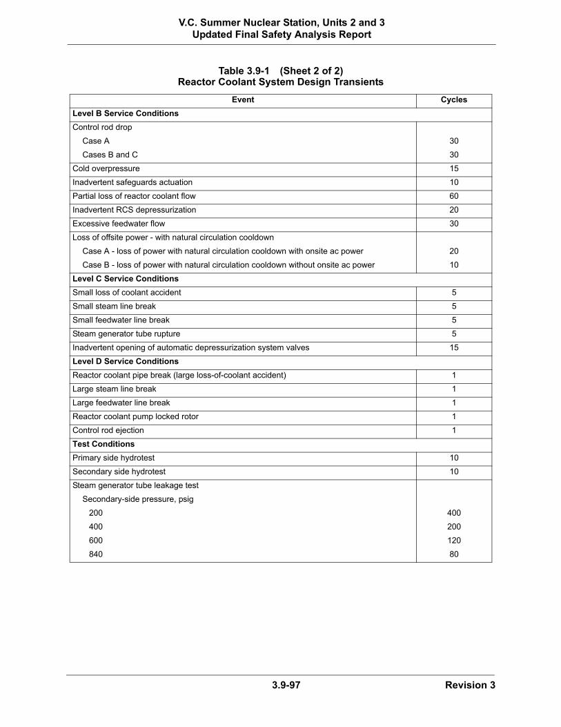
3.9-97 Revision 3
V.C. Summer Nuclear Station, Units 2 and 3Updated Final Safety Analysis Report
Table 3.9-1 (Sheet 2 of 2)Reactor Coolant System Design Transients
Event Cycles
Level B Service Conditions
Control rod drop
Case A 30
Cases B and C 30
Cold overpressure 15
Inadvertent safeguards actuation 10
Partial loss of reactor coolant flow 60
Inadvertent RCS depressurization 20
Excessive feedwater flow 30
Loss of offsite power - with natural circulation cooldown
Case A - loss of power with natural circulation cooldown with onsite ac power 20
Case B - loss of power with natural circulation cooldown without onsite ac power 10
Level C Service Conditions
Small loss of coolant accident 5
Small steam line break 5
Small feedwater line break 5
Steam generator tube rupture 5
Inadvertent opening of automatic depressurization system valves 15
Level D Service Conditions
Reactor coolant pipe break (large loss-of-coolant accident) 1
Large steam line break 1
Large feedwater line break 1
Reactor coolant pump locked rotor 1
Control rod ejection 1
Test Conditions
Primary side hydrotest 10
Secondary side hydrotest 10
Steam generator tube leakage test
Secondary-side pressure, psig
200 400
400 200
600 120
840 80

3.9-98 Revision 3
V.C. Summer Nuclear Station, Units 2 and 3Updated Final Safety Analysis Report
Table 3.9-2 Pump Starting/Stopping Conditions
Plant ConditionRCS
(°F)/(psig)SG Secondary
(°F)/(psig)Number of
Starts/Stops Operation
Cold 70/400 70/0 200 Cold Startup Transients
Cold 70/400 70/0 200 RCS heatup, cooldown
Restart 100/400 100/0 400 Hot functional RCP stops, starts
Hot 557/2235 557/1091 2200 Transients and miscellaneous

3.9-99 Revision 3
V.C. Summer Nuclear Station, Units 2 and 3Updated Final Safety Analysis Report
Table 3.9-3 (Sheet 1 of 2)Loadings for ASME Class 1, 2, 3, CS and Supports
Load Description
P Internal design pressure
PMAX Peak pressure
DW Dead weight
DML Design Mechanical Loads (other than DW). This includes Service Level A loads and RVOS loads that are Service Level B.
XL External mechanical loads, such as the nozzle reactions associated with piping systems, shall be combined with other loads in the loading combination expressions.
SSE Safe shutdown earthquake (inertia portion)
E Earthquake smaller than SSE (inertia portion)
FV Fast valve closure
RVC Relief/safety valve - closed system (transient)
RVOS Relief/safety valve - open system (sustained)
RVOT Relief/safety valve - open system (transient)
DY Dynamic load associated with various service conditions including FV, RVC, and RVOT as applicable (transient)
DN Dynamic load associated with Level A (Normal) service conditions including FV, RVC, and RVOT as applicable (transient)
DU Dynamic load associated with Level B (Upset) service conditions including FV, RVC, and RVOT as applicable (transient)
DE Dynamic load associated with Level C (Emergency) service conditions including FV, RVC, and RVOT as applicable (transient)
DF Dynamic load associated with Level D (Faulted) service conditions during which, or following which, the piping system being evaluated must remain intact including FV, RVC, and RVOT as applicable. This includes postulated pipe rupture events (transient)
DYS Dynamic load associated with various service conditions (sustained)
SSES Seismic anchor motion portion of SSE
ES Seismic anchor motion of earthquake smaller than SSE
TH Thermal loads for the various service conditions

3.9-100 Revision 3
V.C. Summer Nuclear Station, Units 2 and 3Updated Final Safety Analysis Report
TNU Service Level A and B (normal and upset) plant condition thermal loads; including thermal stratification and thermal cycling
TN Service Level A (normal) plant condition thermal loads
TU Service Level B (upset) plant condition thermal loads
TE Service Level C (emergency) plant condition thermal loads
TF Service Level D (faulted) plant condition thermal loads
SCVNU Static displacement of steel containment vessel - normal and upset conditions
SCVE Static displacement of steel containment vessel - emergency condition
SCVF Static displacement of steel containment vessel - faulted condition
HTDW Hydrostatic test dead weight
DBPB Design basis pipe break, includes LOCA and non-LOCA (transient)
LOCA Loss-of-coolant accident
HYDSP Building structure motions due to automatic depressurization system sparger discharge
DBPBS Design basis pipe break, includes LOCA and non-LOCA (sustained)
Table 3.9-3 (Sheet 2 of 2)Loadings for ASME Class 1, 2, 3, CS and Supports
Load Description

3.9-101 Revision 3
V.C. Summer Nuclear Station, Units 2 and 3Updated Final Safety Analysis Report
Table 3.9-4First Plant AP1000 Reactor Internals
Vibration Measurement Program Transducer Locations
Instrumented ComponentNumber and Type
of TransducersApproximate Transducer
LocationsDirection of Sensitivity
Core Shroud (Inner Wall) 4 accelerometers 0°, 45°, 180°, 315° Radial
Core Shroud to Core Barrel 4 relative displacement transducers
225°, 315° 2 Radial2 Tangential
Core Barrel Flange (Outer Wall) 4 strain gages 0°, 90, 180°, 270° Axial
Core Barrel Flange (Inner Wall) 1 strain gages 180° Axial
Core Barrel Mid-elevation (Outer Wall)
3 accelerometers 0°, 45°, 180° Radial
Core Barrel Mid-elevation 1 pressure transducer 0° Radial
Upper Support Skirt(Inner Wall)
3 strain gages 0°, 90°, 180° Axial
Upper Support Plate(Outer Wall)
1 strain gage 90° Axial
Upper Support Plate to Instrumentation Grid Assembly (IGA)
3 relative displacement transducers
Periphery of plate Horizontal
Lower Core Support Plate Weld 1 accelerometer Near the center of the plate Vertical
Vortex Suppression Plate Support Columns (2)
4 strain gages On outside columns at an elevation near LCSP with 3 gages on one column and 1 gage on another column; these two columns are 180° apart
Axial
Reactor Vessel (Head Studs) 4 accelerometers Studs at 0°, 90°, 180°, 270° Vertical
3 accelerometers Stud at 0°, stud at 180° (x-direction), stud at 180°(y-direction)
Horizontal
Instrumentation Grid Assembly (IGA) to Upper Support Plate
1 relative displacement transducer
Center of plate Vertical
IGA Guide Tubes (2) 4 strain gages 0°, 90° Axial
IGA Guide Tube Support 3 strain gages Bottom of support Axial
Lower Guide Tube on B-6 4 strain gages 0°, 90°, 180°, 270° Axial
Upper Guide Tube on B-6 2 strain gages 0°, 90° Axial
Upper Support Column on B-7 4 strain gages 0°, 90°, 180°, 270° Axial

*NRC Staff approval is required prior to implementing a change in this information.
3.9-102 Revision 3
V.C. Summer Nuclear Station, Units 2 and 3Updated Final Safety Analysis Report
Notes:1. The values of PMAX in the load combinations may be different for different levels of service conditions as provided
in the design transients. For earthquake loadings PMAX is equal to normal operating pressure at 100% power.2. SRSS equals the square root of the sum of the squares.3. Appropriate loads due to static displacements of the steel containment vessel and building settlement should be
added to the loading combinations expressions for ASME Code, Section III, Class 2 and 3 systems.4. In combining loads, the timing and causal relationships that exist between PMAX, and XL, are considered for
determination of the appropriate load combinations.5. The pressurizer safety valve discharge is a Level C service condition.6. See Table 3.9-3 for description of loads.7. For components that behave as anchors to the piping system, such as equipment nozzles, SSE and SSES are
combined by absolute sum. For other components, such as straight pipe, tees, and valves, SSE and SSES are combined by SRSS method.
8. In combining loads, the timing and causal relationships that exist between PMAX, DN, DU, DE, DF, and XL, are considered for determination of the appropriate load combinations.
9. In combining loads, the timing and causal relationships that exist between PMAX, DY, HYDSP, and XL, are considered for determination of the appropriate load combinations.
10. In combining loads, the timing and causal relationships that exist between PMAX, DY, and XL, are considered for determination of the appropriate load combinations.
11. In combining loads, the timing and causal relationships that exist between PMAX, RVOS, and XL, are considered for determination of the appropriate load combinations.
Table 3.9-5Minimum Design Loading Combinations for
ASME Class 1, 2, 3 and CS Systems and Components
Condition Design Loading Combinations(3)(6)
[Design P + DW + DML + XL
Level A Service PMAX(1) + DW + XL(4)
PMAX + DW + DN + XL(8)
Level B Service PMAX + DW + DU + XL(8)
Level C Service PMAX + DW + DE(5) + XL(8)
PMAX + DW + DY + HYDSP + XL(9)
Level D Service PMAX + DW + DF + XL(8)
PMAX + DW + SRSS(2) ((SSE + SSES) + DBPB)(7) + XL(4)
PMAX + DW + RVOS + SRSS (SSE + SSES)(7) + XL(11)
PMAX + DW + DYS + DBPBS + SRSS ((SSE + SSES)(7) + DY + HYDSP) + XL(9)(10)]*

*NRC Staff approval is required prior to implementing a change in this information.
3.9-103 Revision 3
V.C. Summer Nuclear Station, Units 2 and 3Updated Final Safety Analysis Report
Notes:1. The values of PMAX in the load combinations may be different for different levels of service conditions. For earthquake loading,
PMAX is equal to normal operating pressure at 100% power.2. Pressurizer safety valve discharge is classified as a Level C event.3. See Table 3.9-11 for functional capability requirements.4. The earthquake loads are assumed to occur at normal 100 percent power operation for the purposes of determining the total
moment ranges.5. Square root sum of the squares (SRSS) combination is used for ES, E, and other transient loads.6. FAM is amplitude of axial force for SSES; AM is nominal pipe metal area.7. See Table 3.9-3 for description of loads.8. Where:M1 is range of moments for TNU, M2 is one half the range of SSES moments,
M1 + M2 is larger of M1 plus one half the range of SSES, or full range of SSESC2, Do, I based on ASME III
Table 3.9-6Additional Load Combinations and Stress Limits for ASME Class 1 Piping
Condition Loads(7)Equation (NB3650) Stress Limit
[Level A/B PMAX(1), TNU, E, ES, RVC, DN, DU, SCVNU(2)(4)(5)
RVOS(2)
1011, 14
3.0 SmCUF = 1.0
TNU 12 3.0 Sm
PMAX + DW + DUPMAX + DW + RVOS(2)
1313
3.0 Sm 3.0 Sm
Level C TE + SCVE Note 3 Note 3
Level D(8) SSESTF + SCVFTNU + SSES
FAM/AM(6)
Note 3C2Do (M1 + M2)/2I(8)
1.0 SmNote 3
6.0 Sm]*

*NRC Staff approval is required prior to implementing a change in this information.
3.9-104 Revision 3
V.C. Summer Nuclear Station, Units 2 and 3Updated Final Safety Analysis Report
Notes:1. The values of PMAX in the load combinations may be different for different levels of service conditions. For earthquake
loading PMAX is equal to normal operating pressure at 100% power.2. Where: M1 is range of moments for TNU, M2 is one half the range of SSES moments, M1 + M2 is larger of
M1 plus one half the range of SSES, or full range of SSES3. See Table 3.9-3 for description of loads.4. The timing and causal relationships among TNU, TE, TF, SCVNU, SCVE, and SCVF are considered to determine
appropriate load combinations.5. FAM is amplitude of axial force for SSES; AM is nominal pipe metal area.6. See Table 3.9-11 for functional capability requirements.
Table 3.9-7Additional Load Combinations and Stress Limits for ASME Class 2, 3 Piping
Condition Loads(3)Equation
(NC/ND3650) Stress Limit
[Level A/B PMAX(1) + DW + TNU + SCVNU(4) 11 Sh + SA
Building Settlement 10a 3.0 SC
Level C TE + SCVE(4) Note 6 Note 6
Level D TNU + SSES i (M1 + M2)/Z(2) 3.0 Sh
SSES FAM/AM(5) 1.0 Sh
TF + SCVF(4) Note 6 Note 6]*
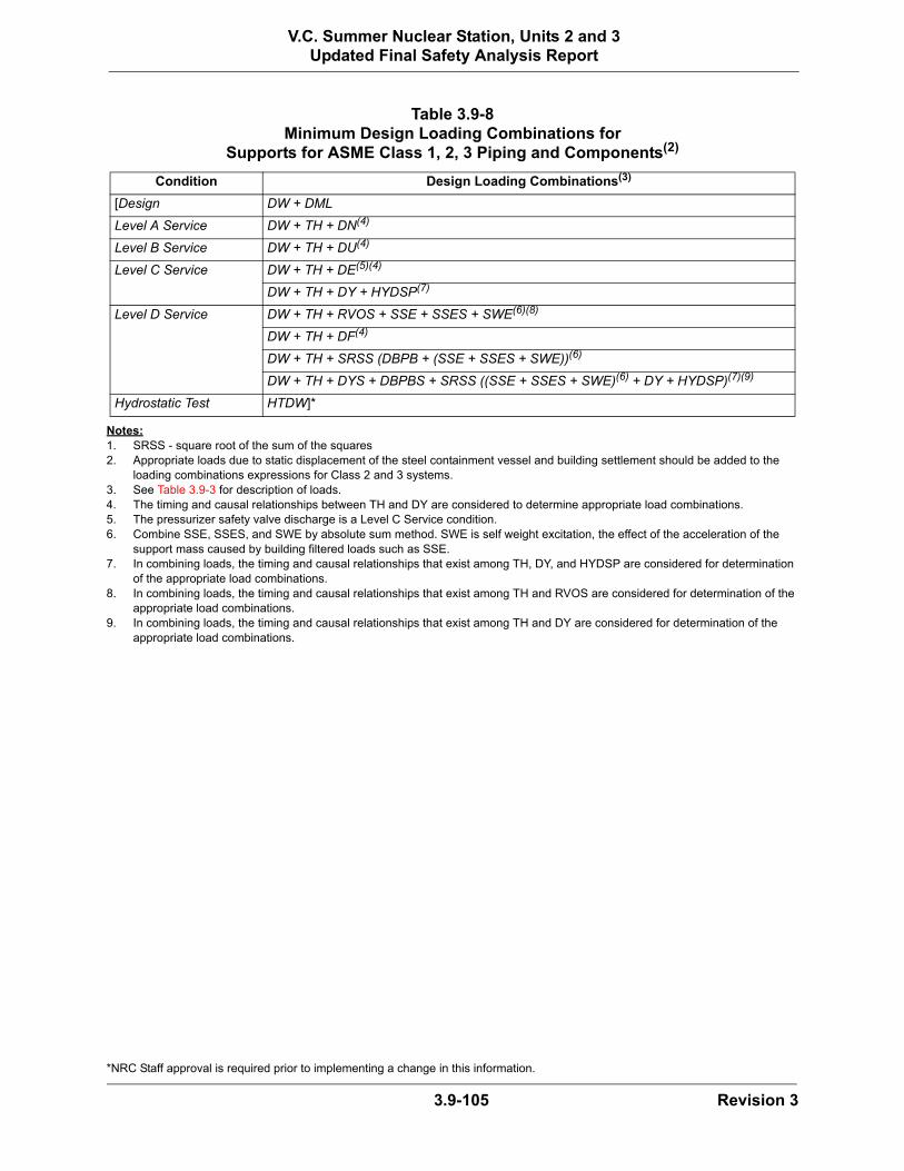
*NRC Staff approval is required prior to implementing a change in this information.
3.9-105 Revision 3
V.C. Summer Nuclear Station, Units 2 and 3Updated Final Safety Analysis Report
Notes:1. SRSS - square root of the sum of the squares2. Appropriate loads due to static displacement of the steel containment vessel and building settlement should be added to the
loading combinations expressions for Class 2 and 3 systems.3. See Table 3.9-3 for description of loads.4. The timing and causal relationships between TH and DY are considered to determine appropriate load combinations.5. The pressurizer safety valve discharge is a Level C Service condition.6. Combine SSE, SSES, and SWE by absolute sum method. SWE is self weight excitation, the effect of the acceleration of the
support mass caused by building filtered loads such as SSE.7. In combining loads, the timing and causal relationships that exist among TH, DY, and HYDSP are considered for determination
of the appropriate load combinations.8. In combining loads, the timing and causal relationships that exist among TH and RVOS are considered for determination of the
appropriate load combinations.9. In combining loads, the timing and causal relationships that exist among TH and DY are considered for determination of the
appropriate load combinations.
Table 3.9-8Minimum Design Loading Combinations for
Supports for ASME Class 1, 2, 3 Piping and Components(2)
Condition Design Loading Combinations(3)
[Design DW + DML
Level A Service DW + TH + DN(4)
Level B Service DW + TH + DU(4)
Level C Service DW + TH + DE(5)(4)
DW + TH + DY + HYDSP(7)
Level D Service DW + TH + RVOS + SSE + SSES + SWE(6)(8)
DW + TH + DF(4)
DW + TH + SRSS (DBPB + (SSE + SSES + SWE))(6)
DW + TH + DYS + DBPBS + SRSS ((SSE + SSES + SWE)(6) + DY + HYDSP)(7)(9)
Hydrostatic Test HTDW]*

*NRC Staff approval is required prior to implementing a change in this information.
3.9-106 Revision 3
V.C. Summer Nuclear Station, Units 2 and 3Updated Final Safety Analysis Report
Notes:a. A test of the components may be performed in lieu of analysis.b. Class 1 valve service Level D criteria for inactive valves is based on the criteria in ASME III, Appendix F, F-1420 for verification of pressure boundary integrity.c. Including pipe supports.d. In instances where the determination of allowable stress values utilizes Su (ultimate tensile stress) at temperatures not included in ASME Code Section III, Su shall be calculated
using one of the methods provided in Regulatory Guide 1.124, Revision 1.e. ASME Table 3131(a)-1.f. See Subsection 3.9.3.4 for supports for active equipment, valves, and piping with active valves.g. For active valves, pressure integrity verification will be based on using the ASME Code allowables one level less than the service loading condition. For example, for the
evaluation of Level D loading, Level C allowables will be used. Valve operability is demonstrated by testing or analysis. Check valve operability may be shown by analysis. See Subsection 3.9.3.2.2 for an outline of test requirements.
h. Table 3.9-6 includes additional stress limits for Class 1 piping.
Table 3.9-9Stress Criteria for ASME Code Section III
Class 1 Components(a) and Supports and Class CS Core Supports
Design/Service Level Vessels/Tanks Pumps Piping (h) Core Supports Valves, Disks & Seats
Components Supports (c,d)
Design and Service Level A
ASME Code, Section III NB-3221, 3222
[ASME Code, Section III NB-3652, Equation 9]*
ASME Code, Section III NG-3221, 3222, 3231, 3232
ASME Code, Section III NB-3520, 3525
[ASME Code, Section III Subsection NF (e)]*
Service Level B (Upset)
ASME Code, Section III NB-3223
[ASME Code, Section III NB-3654, Equation 9]*
ASME Code, Section III NG-3223, 3233
ASME Code, Section III NB-3525
[ASME Code, Section III Subsection NF (e)]*
Service Level C (Emergency)
ASME Code, Section III NB-3224
[ASME Code, Section III NB-3655, Equation 9]*
ASME Code, Section III NG-3224, 3234
ASME Code, Section III NB-3526
[ASME Code, Section III Subsection NF (e)]*
Service Level D (Faulted)
ASME Code, Section III (see Chapter 3.9.1.4) NB-3225 (no active Class 1 pumps used)
[ASME Code, Section III NB-3656, Equation 9]*
ASME Code, Section III (see chapter 3.9.1) NG-3225, 3235
(b) (g) [ASME Code, Section III Subsection NF, (e) (see Chapter 3.9.1) (f)]*

*NRC Staff approval is required prior to implementing a change in this information.
3.9-107 Revision 3
V.C. Summer Nuclear Station, Units 2 and 3Updated Final Safety Analysis Report
See following page for notes.
Table 3.9-10Stress Criteria for ASME Code Section IIIClass 2 and 3 Components and Supports
Design/ Service Level Vessels/Tanks Piping (f) Pumps Valves, Disks, SeatsComponent Supports
(a) (b)
Design and Service Level A
ASME Code Section III NC-3217 NC/ND-3310, 3320
[ASME Code, Section III NC/ND-3652, Equation 8]*
ASME Code Section III NC/ND-3400
ASME Code Section III NC/ND-3510
[ASME CodeSection III (c)]*
Service Level B (Upset)
ASME Code Section III NC/ND-3310, 3320
[ASME Code, Section III NC/ND-3653, Equation 9]*
ASME Code Section III NC/ND-3400
ASME Code Section III NC/ND-3520
[ASME Code Section III (c)]*
Service Level C (Emergency)
ASME Code Section III NC/ND-3310, 3320
[ASME Code, Section III NC/ND-3654, Equation 9]*
ASME Code Section III NC/ND-3400
ASME Code Section III NC/ND-3520
[ASME Code Section III (c)]*
Service Level D (Faulted)
ASME Code Section III NC/ND-3310, 3320
[ASME Code, Section III NC/ND-3655, Equation 9]*
ASME Code Section III NC/ND-3400
ASME Code Section III NC/ND-3520 (e)
[ASME CodeSection III (c) (d)]*

3.9-108 Revision 3
V.C. Summer Nuclear Station, Units 2 and 3Updated Final Safety Analysis Report
Notes:a. Including pipe supports.b. In instances where the determination of allowable stress values utilizes Su (ultimate tensile stress) at temperatures not included in ASME Code Section III, Su shall be calculated
using one of the methods provided in Regulatory Guide 1.124, Revision 1.c. ASME Table 3131(a)-1.d. See Subsection 3.9.3.4 for supports for active equipment, valves, and piping with active valves.e. For active valves, pressure integrity verification will be based on using the ASME Code allowables one level less than the service loading condition. For example, for the
evaluation of Level D loading, Level C allowables will be used. Valve operability is demonstrated by testing or analysis. Check valve operability may be shown by analysis. See Subsection 3.9.3.2.2 for an outline of test requirements.
f. Table 3.9-7 includes additional stress limits for Class 2 and 3 piping.

*NRC Staff approval is required prior to implementing a change in this information.
3.9-109 Revision 3
V.C. Summer Nuclear Station, Units 2 and 3Updated Final Safety Analysis Report
Notes:1. Applicable to Level C or Level D plant events for which the piping system must maintain an adequate fluid flow path2. Applicable to ASME Code Class 1 piping3. Applicable to ASME Code Class 2 and 3 piping4. Applicable to ASME Code Class 1, 2 and 3 piping when the following limitations are met:
4.1 Dynamic loads are reversing (slug-flow water hammer loads are non-reversing)4.2 Slug-flow water-hammer loads are combined with other design basis loads (for example: SSE; pipe break loads) 4.3 Steady-state bending stress from deadweight loads does not exceed:
4.4 When elastic response spectrum analysis is used, dynamic moments are calculated using 15% peak broadening and not more than 5% damping
5. For Class 1 piping, when slug-flow water hammer loads are only combined with pressure, weight and other sustained mechanical loads, the Equation 9 stress does not exceed the smaller of 1.8 Sy and 2.25 Sm.
6. For Class 2 and 3 piping, when slug-flow water hammer loads are only combined with pressure, weight and other sustained mechanical loads, the Equation 9 stress does not exceed the smaller of 1.8 Sy and 2.25 Sh.
Table 3.9-11Piping Functional Capability – ASME
Class 1, 2, and 3(1)
[Wall Thickness: Do/t ≤ 50, where Do, t are per ASME III
Service Level D Conditions Equation 9 ≤ smaller of 2.0 Sy and 3.0 Sm(2, 4, 5)
Equation 9 ≤ smaller of 2.0 Sy and 3.0 Sh(3, 4, 6)
External Pressure: Pexternal ≤ Pinternal
TE + SCVE C2*M*Do/2I ≤ 6.0 Sm(2) (NB-3650)
Equation 10a (NC3653.2) ≤ 3.0 Sc(3)
TF + SCVF C2*M*Do/2I ≤ 6.0 Sm(2) (NB-3650)
Equation 10a (NC 3653.2) ≤ 3.0 Sc(3]*
S 0.25 Z
M * 2BY≤

3.9-110 Revision 3
V.C. Summer Nuclear Station, Units 2 and 3Updated Final Safety Analysis Report
Table 3.9-12 (Sheet 1 of 7)List of ASME Class 1, 2, and 3 Active Valves
Valve No. Description Function(a)
Compressed Air System
CAS-PL-V014 Instrument Air Supply Outside Containment Isolation 2
CAS-PL-V015 Instrument Air Supply Inside Containment Isolation Check Valve 2
CAS-PL-V205 Service Air Supply Inside Containment Isolation Check Valve 2
Component Cooling Water System
CCS-PL-V200 Containment Isolation Valve – Inlet Line Isolation 2, 3
CCS-PL-V201 Containment Isolation Valve – Inlet Line Check Valve 2, 3
CCS-PL-V207 Containment Isolation Valve – Outlet Line Isolation 2, 3
CCS-PL-V208 Containment Isolation Valve – Outlet Line Isolation 2, 3
CCS-PL-V220 Containment Isolation Thermal Relief Valve 2
CCS-PL-V270 CCS IRC Relief Valve 3
CCS-PL-V271 CCS IRC Relief Valve 3
Chemical and Volume Control System
CVS-PL-V001 Reactor Coolant System Purification Stop 1
CVS-PL-V002 Reactor Coolant System Purification Stop 1
CVS-PL-V003 Reactor Coolant System Purification Stop 1
CVS-PL-V042 Flush Line Containment Isolation Relief 2
CVS-PL-V045 Letdown Containment Isolation IRC 2
CVS-PL-V047 Letdown Containment Isolation ORC 2
CVS-PL-V058 Letdown Line Containment Isolation Relief 2
CVS-PL-V067 Makeup Return Line Bypass Check Valve 1
CVS-PL-V080 Reactor Coolant System Purification Return Line Check Valve 1
CVS-PL-V081 Reactor Coolant System Purification Return Line Stop Valve 1
CVS-PL-V082 Reactor Coolant System Purification Return Line Check Valve 1
CVS-PL-V084 Auxiliary Pressurizer Spray Line Isolation 1
CVS-PL-V085 Auxiliary Pressurizer Spray Line Check Valve 1
CVS-PL-V090 Makeup Line Containment Isolation 2
CVS-PL-V091 Makeup Line Containment Isolation 2
CVS-PL-V092 Zinc Injection Containment Isolation Valve ORC 2
CVS-PL-V094 Zinc Injection Containment Isolation Valve IRC 2
CVS-PL-V098 Zinc Addition Line Containment Isolation Thermal Relief Valve 2
CVS-PL-V100 Makeup Line Containment Isolation Thermal Relief Check Valve 2
CVS-PL-V136A Demineralized Water System Isolation 3
CVS-PL-V136B Demineralized Water System Isolation 3
CVS-PL-V217 Hydrogen Injection Containment Isolation Check Valve IRC 2
CVS-PL-V219 Hydrogen Injection Containment Isolation Valve ORC 2
Demineralized Water System
DWS-PL-V245 Demineralized Water Supply Inside Containment Isolation Check Valve 2
RN-12-004
RN-12-004
RN-12-004

3.9-111 Revision 3
V.C. Summer Nuclear Station, Units 2 and 3Updated Final Safety Analysis Report
Table 3.9-12 (Sheet 2 of 7)List of ASME Class 1, 2, and 3 Active Valves
Valve No. Description Function(a)
Fuel Handing System
FHS-PL-V001 Fuel Transfer Tube Isolation Valve 3
Fire Protection System
FPS-PL-V052 Fire Water Supply Inside Containment Isolation Check Valve 2
Passive Containment Cooling System
PCS-PL-V001A Passive Containment Cooling Water Storage Tank Isolation 3,4
PCS-PL-V001B Passive Containment Cooling Water Storage Tank Isolation 3,4
PCS-PL-V001C Passive Containment Cooling Water Storage Tank Isolation 3,4
PCS-PL-V002A Passive Containment Cooling Water Storage Tank Series Isolation 3,4
PCS-PL-V002B Passive Containment Cooling Water Storage Tank Series Isolation 3,4
PCS-PL-V002C Passive Containment Cooling Water Storage Tank Series Isolation 3,4
PCS-PL-V005 Passive Containment Cooling Water Storage Tank Supply to Fire Protection System Isolation Manual Stop-Check Valve
3,4
PCS-PL-V009 Spent Fuel Pool Emergency Makeup Isolation 3
PCS-PL-V015 Water Bucket Makeup Line Drain Valve 3,4
PCS-PL-V020 Water Bucket Makeup Line Isolation Valve 3,4
PCS-PL-V023 PCS Recirculation Return Isolation Manual Stop Check Valve 3,4
PCS-PL-V039 PCCWST Long-Term Makeup Check Valve 3,4
PCS-PL-V042 PCCWST Long Term Makeup Isolation Drain Valve 3,4
PCS-PL-V044 PCCWST Long Term Makeup Isolation Valve 3,4
PCS-PL-V045 Emergency Makeup to the Spent Fuel Pool Isolation Valve 3
PCS-PL-V046 PCCWST Recirculation Return Isolation Valve 3,4
PCS-PL-V049 Emergency Makeup to the Spent Fuel Pool Drain Isolation Valve 3
PCS-PL-V050 Spent Fuel Pool Long Term Makeup Isolation Valve 3
PCS-PL-V051 Spent Fuel Pool Emergency Makeup Lower Isolation Valve 3
Primary Sampling System
PSS-PL-V008 Containment Isolation – Containment Air Sample Isolation 2
PSS-PL-V010A Containment Isolation – Liquid Sample Line 2
PSS-PL-V010B Containment Isolation – Liquid Sample Line 2
PSS-PL-V011A Containment Isolation – Liquid Sample Line 2
PSS-PL-V011B Containment Isolation – Liquid Sample Line 2
PSS-PL-V023 Containment Isolation – Sample Return Line 2
PSS-PL-V024 Containment Isolation – Sample Return Line 2
PSS-PL-V046 Containment Isolation – Air Sample Line 2
Potable Water System
PWS-PL-V418 PWS MCR Isolation Valve 3
PWS-PL-V420 PWS MCR Isolation Valve 3
PWS-PL-V498 PWS MCR Vacuum Relief 3
RN-13-0

3.9-112 Revision 3
V.C. Summer Nuclear Station, Units 2 and 3Updated Final Safety Analysis Report
Table 3.9-12 (Sheet 3 of 7)List of ASME Class 1, 2, and 3 Active Valves
Valve No. Description Function(a)
Passive Core Cooling System
PXS-PL-V014A Core Makeup Tank A Discharge Isolation 3,4
PXS-PL-V014B Core Makeup Tank B Discharge Isolation 3,4
PXS-PL-V015A Core Makeup Tank A Discharge Isolation 3,4
PXS-PL-V015B Core Makeup Tank B Discharge Isolation 3,4
PXS-PL-V016A Core Makeup Tank A Discharge Check 3,4
PXS-PL-V016B Core Makeup Tank Discharge Check 3,4
PXS-PL-V017A Core Makeup Tank A Discharge Check 3,4
PXS-PL-V017B Core Makeup Tank B Discharge Check 3,4
PXS-PL-V022A Accumulator A Pressure Relief 3
PXS-PL-V022B Accumulator B Pressure Relief 3
PXS-PL-V028A Accumulator A Discharge Check 1,3,4
PXS-PL-V028B Accumulator B Discharge Check 1,3,4
PXS-PL-V029A Accumulator A Discharge Check 1,3,4
PXS-PL-V029B Accumulator B Discharge Check 1,3,4
PXS-PL-V042 Nitrogen Supply Containment Isolation ORC Isolation Valve 2
PXS-PL-V043 Nitrogen Supply Containment Isolation IRC Check Valve 2
PXS-PL-V108A Passive Residual Heat Removal Heat Exchanger Control 3,4
PXS-PL-V108B Passive Residual Heat Removal Heat Exchanger Control 3,4
PXS-PL-V118A Recirculation Sump A Isolation 3,4
PXS-PL-V118B Recirculation Sump B Isolation 3,4
PXS-PL-V119A Recirculation Sump A Check 3,4
PXS-PL-V119B Recirculation Sump B Check 3,4
PXS-PL-V120A Recirculation Sump A Isolation 3,4
PXS-PL-V120B Recirculation Sump B Isolation 3,4
PXS-PL-V122A In-Containment Refueling Water Storage Tank Injection A Check 1,3,4
PXS-PL-V122B In-Containment Refueling Water Storage Tank Injection B Check 1,3,4
PXS-PL-V123A In-Containment Refueling Water Storage Tank Injection A Isolation 1,3,4
PXS-PL-V123B In-Containment Refueling Water Storage Tank Injection B Isolation 1,3,4
PXS-PL-V124A In-Containment Refueling Water Storage Tank Injection A Check 1,3,4
PXS-PL-V124B In-Containment Refueling Water Storage Tank Injection B Check 1,3,4
PXS-PL-V125A In-Containment Refueling Water Storage Tank Injection A Isolation 1,3,4
PXS-PL-V125B In-Containment Refueling Water Storage Tank Injection B Isolation 1,3,4
PXS-PL-130A In-Containment Refueling Water Storage Tank Gutter Isolation 3,4
PXS-PL-130B In-Containment Refueling Water Storage Tank Gutter Isolation 3,4
Reactor Coolant System
RCS-PL-V001A First Stage Automatic Depressurization System 1,3,4
RCS-PL-V001B First Stage Automatic Depressurization System 1,3,4
RCS-PL-V002A Second Stage Automatic Depressurization System 1,3,4
RCS-PL-V002B Second Stage Automatic Depressurization System 1,3,4

3.9-113 Revision 3
V.C. Summer Nuclear Station, Units 2 and 3Updated Final Safety Analysis Report
Table 3.9-12 (Sheet 4 of 7)List of ASME Class 1, 2, and 3 Active Valves
Valve No. Description Function(a)
Reactor Coolant System (Cont.)
RCS-PL-V003A Third Stage Automatic Depressurization System 1,3,4
RCS-PL-V003B Third Stage Automatic Depressurization System 1,3,4
RCS-PL-V004A Fourth Stage Automatic Depressurization System 1,3,4
RCS-PL-V004B Fourth Stage Automatic Depressurization System 1,3,4
RCS-PL-V004C Fourth Stage Automatic Depressurization System 1,3,4
RCS-PL-V004D Fourth Stage Automatic Depressurization System 1,3,4
RCS-PL-V005A Pressurizer Safety Valve 1,3
RCS-PL-V005B Pressurizer Safety Valve 1,3
RCS-PL-V010A Automatic Depressurization System Discharge Header A Vacuum Relief 3
RCS-PL-V010B Automatic Depressurization System Discharge Header B Vacuum Relief 3
RCS-PL-V011A First Stage Automatic Depressurization System Isolation 1,3,4
RCS-PL-V011B First Stage Automatic Depressurization System Isolation 1,3,4
RCS-PL-V012A Second Stage Automatic Depressurization System Isolation 1,3,4
RCS-PL-V012B Second Stage Automatic Depressurization System Isolation 1,3,4
RCS-PL-V013A Third Stage Automatic Depressurization System Isolation 1,3,4
RCS-PL-V013B Third Stage Automatic Depressurization System Isolation 1,3,4
RCS-PL-V150A Reactor Vessel Head Vent 1,3
RCS-PL-V150B Reactor Vessel Head Vent 1,3
RCS-PL-V150C Reactor Vessel Head Vent 1,3
RCS-PL-V150D Reactor Vessel Head Vent 1,3
Normal Residual Heat Removal System
RNS-PL-V001A Reactor Coolant System Inner HL Suction Isolation 1
RNS-PL-V001B Reactor Coolant System Inner HL Suction Isolation 1
RNS-PL-V002A Reactor Coolant System Outer HL Suction Isolation 1,2
RNS-PL-V002B Reactor Coolant System Outer HL Suction Isolation 1,2
RNS-PL-V003A Reactor Coolant System Pressure Boundary Valve Thermal Relief Check Valve
1
RNS-PL-V003B Reactor Coolant System Pressure Boundary Valve Thermal Relief Check Valve
1
RNS-PL-V011 RNS Discharge Containment Isolation Valve 2, 4
RNS-PL-V012 RNS Discharge Containment Isolation Test Connection Valve 4
RNS-PL-V013 RNS Discharge Containment Isolation Check Valve 2, 4
RNS-PL-V015A RNS Discharge Reactor Coolant System Pressure Boundary 1, 4
RNS-PL-V015B RNS Discharge Reactor Coolant System Pressure Boundary 1, 4
RNS-PL-V017A RNS Discharge Reactor Coolant System Pressure Boundary 1, 4
RNS-PL-V017B RNS Discharge Reactor Coolant System Pressure Boundary 1, 4
RNS-PL-V021 RNS HL Suction Pressure Relief 2

3.9-114 Revision 3
V.C. Summer Nuclear Station, Units 2 and 3Updated Final Safety Analysis Report
Table 3.9-12 (Sheet 5 of 7)List of ASME Class 1, 2, and 3 Active Valves
Valve No. Description Function(a)
Normal Residual Heat Removal System (Cont.)
RNS-PL-V022 RNS Suction Header Containment Isolation 2
RNS-PL-V023 RNS Suction from In-Containment Refueling Water Storage Tank Isolation 2
RNS-PL-V045 RNS Pump Discharge Pressure Relief 1
RNS-PL-V061 RNS – Chemical Volume Control System Containment Isolation 2
Sanitary Drainage System
SDS-PL-V001 Sanitary Drainage System Line MCR Isolation 3
SDS-PL-V002 Sanitary Drainage System Line MCR Isolation 3
Spent Fuel Pool Cooling System
SFS-PL-V034 Spent Fuel Pool Cooling System Suction Line Containment Isolation 2
SFS-PL-V035 Spent Fuel Pool Cooling System Suction Line Containment Isolation 2
SFS-PL-V037 Spent Fuel Pool Cooling System Discharge Line Containment Isolation 2
SFS-PL-V038 Spent Fuel Pool Cooling System Discharge Line Containment Isolation 2
SFS-PL-V042 Cask Loading Pit to SFS Pump Suction Isolation Valve 3
SFS-PL-V045 SFS Pump Discharge Line to Cask Loading Pit Isolation Valve 3
SFS-PL-V049 Cask Loading Pit to WLS Isolation Valve 3
SFS-PL-V066 Spent Fuel Pool to Cask Washdown Pit Isolation 3
SFS-PL-V067 Containment Isolation Thermal Relief Valve 2
SFS-PL-V068 Cask Washdown Pit Drain Isolation 3
SFS-PL-V071 Refueling Cavity to Steam Generator Compartment 3
SFS-PL-V072 Refueling Cavity to Steam Generator Compartment 3
Steam Generator System
SGS-PL-V027A Power Operated Relief Valve Block Valve Steam Generator 01 2,3,4
SGS-PL-V027B Power Operated Relief Valve Block Valve Steam Generator 02 2,3,4
SGS-PL-V030A Main Steam Safety Valve Steam Generator 01 2,3,4
SGS-PL-V030B Main Steam Safety Valve Steam Generator 02 2,3,4
SGS-PL-V031A Main Steam Safety Valve Steam Generator 01 2,3,4
SGS-PL-V031B Main Steam Safety Valve Steam Generator 02 2,3,4
SGS-PL-V032A Main Steam Safety Valve Steam Generator 01 2,3,4
SGS-PL-V032B Main Steam Safety Valve Steam Generator 02 2,3,4
SGS-PL-V033A Main Steam Safety Valve Steam Generator 01 2,3,4
SGS-PL-V033B Main Steam Safety Valve Steam Generator 02 2,3,4
SGS-PL-V034A Main Steam Safety Valve Steam Generator 01 2,3,4
SGS-PL-V034B Main Steam Safety Valve Steam Generator 02 2,3,4
SGS-PL-V035A Main Steam Safety Valve Steam Generator 01 2,3,4
SGS-PL-V035B Main Steam Safety Valve Steam Generator 02 2,3,4
SGS-PL-V036A Steam Line Condensate Drain Isolation 2,3,4
SGS-PL-V036B Steam Line Condensate Drain Isolation 2,3,4

3.9-115 Revision 3
V.C. Summer Nuclear Station, Units 2 and 3Updated Final Safety Analysis Report
Table 3.9-12 (Sheet 6 of 7)List of ASME Class 1, 2, and 3 Active Valves
Valve No. Description Function(a)
Steam Generator System (Cont.)
SGS-PL-V040A Main Steam Line Isolation 2,3,4
SGS-PL-V040B Main Steam Line Isolation 2,3,4
SGS-PL-V057A Main Feedwater Isolation 2,3,4
SGS-PL-V057B Main Feedwater Isolation 2,3,4
SGS-PL-V067A Startup Feedwater Isolation 2,3,4
SGS-PL-V067B Startup Feedwater Isolation 2,3,4
SGS-PL-V074A Steam Generator Blowdown Isolation 2,3,4
SGS-PL-V074B Steam Generator Blowdown Isolation 2,3,4
SGS-PL-V075A Steam Generator Series Blowdown Isolation 3,4
SGS-PL-V075B Steam Generator Series Blowdown Isolation 3,4
SGS-PL-V086A Steam Line Condensate Drain Control 3,4
SGS-PL-V086B Steam Line Condensate Drain Control 3,4
SGS-PL-V233A Power Operated Relief Valve 3,4
SGS-PL-V233B Power Operated Relief Valve 3,4
SGS-PL-V240A Main Steam Isolation Valve Bypass Isolation 2,3,4
SGS-PL-V240B Main Steam Isolation Valve Bypass Isolation 2,3,4
SGS-PL-V250A Main Feedwater Control 3,4
SGS-PL-V250B Main Feedwater Control 3,4
SGS-PL-V255A Startup Feedwater Control 3,4
SGS-PL-V255B Startup Feedwater Control 3,4
Nuclear Island Nonradioactive Ventilation System
VBS-PL-V186 MCR Supply Air Isolation Valve 3
VBS-PL-V187 MCR Supply Air Isolation Valve 3
VBS-PL-V188 MCR Return Air Isolation Valve 3
VBS-PL-V189 MCR Return Air Isolation Valve 3
VBS-PL-V190 MCR Exhaust Air Isolation Valve 3
VBS-PL-V191 MCR Exhaust Air Isolation Valve 3
Main Control Room Habitability System
VES-PL-V001 Air Delivery Alternate Isolation Valve 3
VES-PL-V002A Pressure Regulating Valve A 3
VES-PL-V002B Pressure Regulating Valve B 3
VES-PL-V005A Air Delivery Isolation Valve A 3
VES-PL-V005B Air Delivery Isolation Valve B 3
VES-PL-V022A Pressure Relief Isolation Valve A 3
VES-PL-V022B Pressure Relief Isolation Valve B 3
VES-PL-V040A Air Tank Safety Relief Valve A 3
VES-PL-V040B Air Tank Safety Relief Valve B 3

3.9-116 Revision 3
V.C. Summer Nuclear Station, Units 2 and 3Updated Final Safety Analysis Report
Note:a. Function: 1 – Reactor coolant system pressure boundary
2 – Containment isolation3 – Accident mitigation4 – Safe shutdown
Table 3.9-12 (Sheet 7 of 7)List of ASME Class 1, 2, and 3 Active Valves
Valve No. Description Function(a)
Main Control Room Habitability System (Cont.)
VES-PL-V041A Air Tank Safety Relief Valve A 3
VES-PL-V041B Air Tank Safety Relief Valve B 3
VES-PL-V044 Main Air Flow Path Isolation Valve 3
VES-PL-V045 Eductor Flow Path Isolation Valve 3
VES-PL-V046 Eductor Bypass Isolation Valve 3
Containment Air Filtration System
VFS-PL-V003 Containment Purge Inlet Containment Isolation Valve 2
VFS-PL-V004 Containment Purge Inlet Containment Isolation Valve 2
VFS-PL-V009 Containment Purge Discharge Containment Isolation Valve 2
VFS-PL-V010 Containment Purge Discharge Containment Isolation Valve 2
VFS-PL-V800A Vacuum Relief Containment Isolation A ORC 2
VFS-PL-V800B Vacuum Relief Containment Isolation B ORC 2
VFS-PL-V803A Vacuum Relief Containment Isolation Check Valve A IRC 2
VFS-PL-V803B Vacuum Relief Containment Isolation Check Valve B IRC 2
Central Chilled Water System
VWS-PL-V058 Fan Coolers Supply Containment Isolation 2
VWS-PL-V062 Fan Coolers Supply Containment Isolation Check Valve 2
VWS-PL-V080 Containment Isolation Thermal Relief Valve 2
VWS-PL-V082 Fan Coolers Return Containment Isolation 2
VWS-PL-V086 Fan Coolers Return Containment Isolation 2
Liquid Radwaste System
WLS-PL-V055 Sump Containment Isolation IRC 2
WLS-PL-V057 Sump Containment Isolation ORC 2
WLS-PL-V058 Containment Isolation Relief Valve 2
WLS-PL-V067 Reactor Coolant Drain Tank Gas Containment Isolation IRC 2
WLS-PL-V068 Reactor Coolant Drain Tank Gas Containment Isolation ORC 2
WLS-PL-V071A Chemical and Volume Control System Compartment to Sump 3
WLS-PL-V071B Passive Core Cooling System A Compartment to Sump 3
WLS-PL-V071C Passive Core Cooling System B Compartment to Sump 3
WLS-PL-V072A Chemical and Volume Control System Compartment to Sump 3
WLS-PL-V072B Passive Core Cooling System A Compartment to Sump 3
WLS-PL-V072C Passive Core Cooling System B Compartment to Sump 3

3.9-117 Revision 3
V.C. Summer Nuclear Station, Units 2 and 3Updated Final Safety Analysis Report
Table 3.9-13Control Rod Drive Mechanism Production Tests
Test Acceptance Standard
Cold (ambient) hydrostatic ASME Code, Section III
Confirm step length and load transfer(stationary gripper to movable gripper ormovable gripper to stationary gripper)
Step length:0.625+0.015 inch axial movement
Load transfer:0.055 inch nominal axial movement
Cold (ambient) performance test at design load -five full travel excursions
Operating speed:45 inches/minute
Trip delay:Free fall of drive rod to begin within150 milliseconds
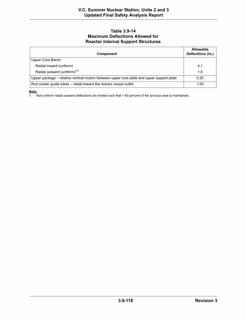
3.9-118 Revision 3
V.C. Summer Nuclear Station, Units 2 and 3Updated Final Safety Analysis Report
Note:1. Non-uniform radial outward deflections are limited such that > 90-percent of the annulus area is maintained.
Table 3.9-14Maximum Deflections Allowed for
Reactor Internal Support Structures
ComponentAllowable
Deflections (in.)
Upper Core Barrel
Radial inward (uniform) 4.1
Radial outward (uniform)(1) 1.0
Upper package – relative vertical motion between upper core plate and upper support plate 0.20
Rod cluster guide tubes – radial toward the reactor vessel outlet 1.00

3.9-119 Revision 3
V.C. Summer Nuclear Station, Units 2 and 3Updated Final Safety Analysis Report
Table 3.9-15Computer Programs for Seismic Category 1 Components
Program Application
ABAQUS Finite element structural analysis
ANSYS Finite element structural analysis
FATCON ASME fatigue analysis of piping components
GAPPIPE Static and dynamic analysis of piping systems
MAXTRAN Transient stress evaluation of piping components
WESTEMS ASME Class 1 fatigue analysis of piping and components
PIPESTRESS Static and dynamic analysis of piping systems
PIPSAN Structural and ASME stress analysis of piping and component supports
GTSTRUDL Structural and ASME stress analysis of piping and component supports and structural frames
STAAD-III Static and dynamic analysis of structural frames
THERST Transient heat transfer analysis of piping components
WECAN Finite element structural analysis
WEGAP Dynamic structural response of the reactor core
WECEVAL ASME stress evaluation of mechanical components
ITCH Transient hydraulic analysis
FORFUN Computes unbalanced hydraulic forces between piping elbows
RELAP-5 Transient dynamic analysis
THRUST Computes time-history hydraulic forcing functions
MULTIFLEX Thermal-hydraulic-structural system analysis
MULTIFLEX-SG Transient dynamic analysis
GEC2 Computes time-history hydraulic forcing functions
FATSTR ASME stress evaluation of piping components
HSTA Hydraulic system transient analysis
E0781 Axisymmetric containment shell analysis
FLOW 3D Finite element fluid flow and heat transfer
RN-14-089

3.9-120 Revision 3
V.C. Summer Nuclear Station, Units 2 and 3Updated Final Safety Analysis Report
Table 3.9-16 (Sheet 1 of 20)Valve Inservice Test Requirements
Valve Tag Number Description(1)
Valve/Actuator Type
Safety-Related Missions Safety Functions(2)
ASME Class/ IST Category
Inservice Testing Type and Frequency IST Notes
CAS-PL-V014 Instrument Air Supply Outside Containment Isolation
Remote AO Butterfly
Maintain CloseTransfer Close
Active-to-Failed Containment Isolation Safety Seat LeakageRemote Position
Class 2 Category A
Remote Position Indication, Exercise/2 YearsContainment Isolation Leak TestExercise Full Stroke/Refueling ShutdownFailsafe Test/Refueling ShutdownOperability Test
18, 27, 31
CAS-PL-V015 Instrument Air Supply Inside Containment Isolation
Check Maintain CloseTransfer Close
Active Containment Isolation Safety Seat Leakage
Class 2 Category AC
Containment Isolation Leak TestCheck Exercise/Refueling Shutdown
18, 27
CAS-PL-V204 Service Air Supply Outside Containment Isolation
Manual Maintain Close Containment Isolation Safety Seat Leakage
Class 2 Category A
Containment Isolation Leak Test 27
CAS-PL-V205 Service Air Supply Inside Containment Isolation
Check Maintain CloseTransfer Close
ActiveContainment IsolationSafety Seat Leakage
Class 2 Category AC
Containment Isolation Leak TestExercise Full Stroke/Refueling Shutdown
27, 37
CCS-PL-V200 CCS Containment Isolation Valve - Inlet Line ORC
Remote MO Butterfly
Maintain CloseTransfer Close
Active Containment Isolation Safety Seat LeakageRemote Position
Class 2 Category A
Remote Position Indication, Exercise/2 YearsContainment Isolation Leak TestExercise Full Stroke/Cold ShutdownOperability Test
14, 27, 31
CCS-PL-V201 CCS Containment Isolation Valve - Inlet Line IRC
Check Maintain CloseTransfer Close
ActiveContainment Isolation Safety Seat Leakage
Class 2 Category AC
Containment Isolation Leak TestCheck Exercise/Cold Shutdown
14, 27
CCS-PL-V207 CCS Containment Isolation Valve - Outlet Line IRC
Remote MO Butterfly
Maintain CloseTransfer Close
Active Containment Isolation Safety Seat Leakage Remote Position
Class 2 Category A
Remote Position Indication, Exercise/2 YearsContainment Isolation Leak TestExercise Full Stroke/Cold ShutdownOperability Test
14, 27, 31
CCS-PL-V208 CCS Containment Isolation Valve - Outlet Line ORC
Remote MO Butterfly
Maintain CloseTransfer Close
ActiveContainment Isolation Safety Seat Leakage Remote Position
Class 2 Category A
Remote Position Indication, Exercise/2 YearsContainment Isolation Leak TestExercise Full Stroke/Cold ShutdownOperability Test
14, 27, 31
CCS-PL-V220 CCS Containment Isolation Thermal Relief Valve
Relief Maintain CloseTransfer CloseTransfer Open
ActiveContainment IsolationSafety Seat Leakage
AC Containment Isolation Leak Test/2 Years 27
CCS-PL-V270 CCS IRC Relief Valve Relief Maintain CloseTransfer CloseTransfer Open
Active Class 3Category BC
Class 2/3 Relief Valve Tests/10 Years and 20% in 4 years
CCS-PL-V271 CCS IRC Relief Valve Relief Maintain CloseTransfer CloseTransfer Open
Active Class 3Category BC
Class 2/3 Relief Valve Tests/10 Years and 20% in 4 years
CVS-PL-V001 RCS Purification Stop Remote MO GATE Maintain CloseTransfer Close
Active Safety Seat LeakageRemote Position
Class 1 Category B
Remote Position Indication, Exercise/2 YearsRCS Isolation Leak Test/RefuelingExercise Full Stroke/Cold ShutdownOperability Test
6, 31, 32
CVS-PL-V002 RCS Purification Stop Remote MO GATE Maintain CloseTransfer Close
ActiveSafety Seat Leakage Remote Position
Class 1 Category B
Remote Position Indication, Exercise/2 YearsRCS Isolation Leak Test/RefuelingExercise Full Stroke/Cold ShutdownOperability Test
6, 31, 32
CVS-PL-V003 RCS Purification Stop Remote MO GLOBE
Maintain CloseTransfer Close
ActiveRemote Position
Class 3 Category B
Remote Position Indication, Exercise/2 YearsExercise Full Stroke/Cold Shutdown Operability Test
6, 31

3.9-121 Revision 3
V.C. Summer Nuclear Station, Units 2 and 3Updated Final Safety Analysis Report
CVS-PL-V040 Resin Flush IRC Isolation Manual Maintain Close Containment IsolationSafety Seat Leakage
Class 2 Category A
Containment Isolation Leak Test 27
CVS-PL-V041 Resin Flush ORC Isolation Manual Maintain Close Containment Isolation Safety Seat Leakage
Class 2 Category A
Containment Isolation Leak Test 27
CVS-PL-V042 Flush Line Containment Isolation Relief
Relief Maintain CloseTransfer OpenTransfer Close
ActiveContainment Isolation Safety Seat Leakage
Class 2 Category AC
Containment Isolation Leak TestClass 2/3 Relief Valve Tests/10 Years and 20% in 4 Years
27
CVS-PL-V045 Letdown Containment Isolation IRC
Remote AO GLOBE
Maintain CloseTransfer Close
Active-to-FailedContainment Isolation Safety Seat Leakage Remote Position
Class 2 Category A
Remote Position Indication, Exercise/2 YearsContainment Isolation Leak TestExercise Full Stroke/QuarterlyFailsafe Test/QuarterlyOperability Test
27, 31
CVS-PL-V047 Letdown Containment Isolation ORC
Remote AO GLOBE
Maintain CloseTransfer Close
Active-to-Failed Containment Isolation Safety Seat LeakageRemote Position
Class 2 Category A
Remote Position Indication, Exercise/2 YearsContainment Isolation Leak TestExercise Full Stroke/QuarterlyFailsafe Test/QuarterlyOperability Test
27, 31
CVS-PL-V058 Letdown Line Containment Isolation Relief
Relief Maintain CloseTransfer OpenTransfer Close
Active Containment Isolation Safety Seat Leakage
AC Containment Isolation Leak Test Class 2/3 Relief Valve Tests/10 Years and 20% in 4 years
27
CVS-PL-V067 Makeup Return Line Bypass Check Valve
Check Maintain CloseTransfer OpenTransfer Close
ActiveSafety Seat Leakage
Class 1Category AC
Check Exercise/Cold ShutdownRCS Isolation Leak Test/Refueling
6, 32
CVS-PL-V080 RCS Purification Return Line Check Valve
Check Maintain CloseTransfer Close
Active Safety Seat Leakage
Class 3 Category C
Check Exercise/Cold ShutdownRCS Isolation Leak Test/Refueling
6, 32
CVS-PL-V081 RCS Purification Return Line Stop Valve
AO Stop Check Maintain CloseTransfer Close
Active Safety Seat Leakage
Class 1 Category C
Check Exercise/Cold ShutdownRCS Isolation Leak Test/Refueling
6, 8, 32
CVS-PL-V082 RCS Purification Return Line Check Valve
Check Maintain CloseTransfer Close
Active Safety Seat Leakage
Class 1 Category C
Check Exercise/Cold ShutdownRCS Isolation Leak Test/Refueling
6, 32
CVS-PL-V084 Auxiliary Pressurizer Spray Line Isolation
Remote AO GLOBE
Maintain CloseTransfer Close
Active-to-Failed Safety Seat LeakageRemote Position
Class 1 Category B
Remote Position Indication, Exercise/2 YearsRCS Isolation Leak Test/RefuelingExercise Full Stroke/Cold ShutdownFailsafe Test/Cold ShutdownOperability Test
22, 31, 32
CVS-PL-V085 Auxiliary Pressurizer Spray Line Check Maintain CloseTransfer Close
Active Safety Seat Leakage
Class 1 Category C
Check Exercise/Cold ShutdownRCS Isolation Leak Test/Refueling
22, 32
CVS-PL-V090 Makeup Line Containment Isolation
Remote MO GATE Maintain CloseTransfer Close
Active Containment IsolationSafety Seat LeakageRemote Position
Class 2 Category A
Remote Position Indication, Exercise/2 YearsContainment Isolation Leak TestExercise Full Stroke/QuarterlyOperability Test
27, 31
CVS-PL-V091 Makeup Line Containment Isolation
Remote MO GATE Maintain CloseTransfer Close
ActiveContainment Isolation Safety Seat LeakageRemote Position
Class 2 Category A
Remote Position Indication, Exercise/2 YearsContainment Isolation Leak TestExercise Full Stroke/QuarterlyOperability Test
27, 31
CVS-PL-V092 Zinc Injection Containment Isolation ORC
Remote AO GLOBE
Maintain CloseTransfer Close
Active-to-FailedContainment Isolation Safety Seat LeakageRemote Position
Class 2 Category A
Remote Position Indication, Exercise/2 YearsContainment Isolation Leak TestExercise Full Stroke/Quarterly OperationFailsafe Test/Quarterly OperationOperability Test
27, 31
Table 3.9-16 (Sheet 2 of 20)Valve Inservice Test Requirements
Valve Tag Number Description(1)
Valve/Actuator Type
Safety-Related Missions Safety Functions(2)
ASME Class/ IST Category
Inservice Testing Type and Frequency IST Notes
RN-12-004
RN-12-004

3.9-122 Revision 3
V.C. Summer Nuclear Station, Units 2 and 3Updated Final Safety Analysis Report
CVS-PL-V094 Zinc Injection Containment Isolation IRC
Remote AOGlobe
Maintain CloseTransfer Close
Active-to-FailedContainment Isolation Safety Seat LeakageRemote Position
Class 2 Category A
Remote Position Indication, Exercise/2 YearsContainment Isolation Leak TestExercise Full Stroke /Quarterly OperationOperability TestFailsafe Test Quarterly
27, 31
CVS-PL-V098 Zinc Addition Line Containment Isolation Thermal Relief Valve
Thermal Relief Maintain CloseTransfer CloseTransfer Open
ActiveContainment IsolationSafety Seat Leakage
Class 2Category AC
Containment Isolation Leak TestClass 2/3 Relief Valve Tests/10 Years and 20% in 4 Years
27
CVS-PL-V100 Makeup Line Containment Isolation Relief
Check Maintain CloseTransfer CloseTransfer Open
ActiveContainment Isolation Safety Seat Leakage
Class 2 Category AC
Containment Isolation Leak Test/2 YearsCheck Exercise/Refueling Shutdown
23, 27
CVS-PL-V136A Demineralized Water System Isolation
Remote AO Butterfly
Maintain CloseTransfer Close
Active-to-FailedRemote Position
Class 3 Category B
Remote Position Indication, Exercise/2 YearsExercise Full Stroke/QuarterlyFailsafe Test/QuarterlyOperability Test
31
CVS-PL-V136B Demineralized Water System Isolation
Remote AO Butterfly
Maintain CloseTransfer Close
Active-to-FailedRemote Position
Class 3 Category B
Remote Position Indication, Exercise/2 YearsExercise Full Stroke/Quarterly Failsafe Test/QuarterlyOperability Test
31
CVS-PL-V217 Hydrogen Injection Containment Isolation Check IRC
Check Maintain CloseTransfer Close
ActiveContainment IsolationSafety Seat Leakage
Class 2Category AC
Containment Isolation Leak TestCheck/Exercise/Quarterly Operation
27
CVS-PL-V219 Hydrogen Injection Containment Isolation ORC
Remote AOGlobe
Maintain CloseTransfer Close
Active-to-FailedContainment IsolationSafety Seat LeakageRemote Position
Class 2Category A
Remote Position Indication, Exercise/2 YearsContainment Isolation Leak TestExercise Full Stroke/Quarterly Operation Operability TestFailsafe Test/Quarterly
27, 31
DWS-PL-V244 Demineralized Water Supply Containment Isolation - Outside
Manual Maintain Close Containment IsolationSafety Seat Leakage
Class 2 Category A
Containment Isolation Leak Test 27
DWS-PL-V245 Demineralized Water Supply Containment Isolation - Inside
Check Maintain CloseTransfer Close
ActiveContainment IsolationSafety Seat Leakage
Class 2 Category AC
Containment Isolation Leak TestExercise Full Stroke/Refueling Shutdown
27, 37
FPS-PL-V050 Fire Water Containment Supply Isolation
Manual Maintain Close Containment Isolation Safety Seat Leakage
Class 2 Category A
Containment Isolation Leak Test 27
FPS-PL-V052 Fire Water Containment Supply Isolation - Inside
Check Maintain CloseTransfer Close
ActiveContainment IsolationSafety Seat Leakage
Class 2 Category AC
Containment Isolation Leak TestExercise Full Stroke/Refueling Shutdown
27, 37
FHS-PL-V001 Fuel Transfer Tube Isolation Valve Manual Transfer CloseMaintain Close
Active Class 3 Category B
Exercise Full Stroke/2 YearsRemote Position Indication, Exercise/2 Years
33, 37
MSS-PL-V001 Turbine Bypass Control Valve Remote AO GLOBE
Maintain Close Transfer Close
Active-to-FailedRemote Position
Non Code Category B
Remote Position Indication, Exercise/2 YearsExercise Full Stroke/Cold ShutdownFailsafe Test/Cold ShutdownOperability Test
29, 31, 34
MSS-PL-V002 Turbine Bypass Control Valve Remote AO GLOBE
Maintain Close Transfer Close
Active-to-FailedRemote Position
Non Code Category B
Remote Position Indication, Exercise/2 YearsExercise Full Stroke/Cold ShutdownFailsafe Test/Cold ShutdownOperability Test
29, 31, 34
Table 3.9-16 (Sheet 3 of 20)Valve Inservice Test Requirements
Valve Tag Number Description(1)
Valve/Actuator Type
Safety-Related Missions Safety Functions(2)
ASME Class/ IST Category
Inservice Testing Type and Frequency IST Notes
RN-12-004
RN-12-004

3.9-123 Revision 3
V.C. Summer Nuclear Station, Units 2 and 3Updated Final Safety Analysis Report
MSS-PL-V003 Turbine Bypass Control Valve Remote AO GLOBE
Maintain Close Transfer Close
Active-to-FailedRemote Position
Non Code Category B
Remote Position Indication, Exercise/2 YearsExercise Full Stroke/Cold Shutdown Failsafe Test/Cold ShutdownOperability Test
29, 31, 34
MSS-PL-V004 Turbine Bypass Control Valve Remote AO GLOBE
Maintain Close Transfer Close
Active-to-FailedRemote Position
Non Code Category B
Remote Position Indication, Exercise/2 YearsExercise Full Stroke/Cold Shutdown Failsafe Test/Cold ShutdownOperability Test
29, 31, 34
MSS-PL-V005 Turbine Bypass Control Valve Remote AO GLOBE
Maintain Close Transfer Close
Active-to-FailedRemote Position
Non Code Category B
Remote Position Indication, Exercise/2 YearsExercise Full Stroke/Cold Shutdown Failsafe Test/Cold ShutdownOperability Test
29, 31, 34
MSS-PL-V006 Turbine Bypass Control Valve Remote AO GLOBE
Maintain Close Transfer Close
Active-to-FailedRemote Position
Non Code Category B
Remote Position Indication, Exercise/2 YearsExercise Full Stroke/Cold Shutdown Failsafe Test/Cold ShutdownOperability Test
29, 31, 34
MSS-PL-V015A Moisture Separator Reheater 2nd Stage Steam Isolation Valve
Remote AO GLOBE
Maintain Close Transfer Close
Active-to-FailedRemote Position
Non Code Category B
Remote Position Indication, Exercise/2 YearsExercise Part Stroke/OperationExercise Full Stroke/Cold ShutdownFailsafe Test/Cold ShutdownOperability Test
25, 31, 34
MSS-PL-V015B Moisture Separator Reheater 2nd Stage Steam Isolation Valve
Remote AO GLOBE
Maintain Close Transfer Close
Active-to-FailedRemote Position
Non Code Category B
Remote Position Indication, Exercise/2 YearsExercise Part Stroke/OperationExercise Full Stroke/Cold ShutdownFailsafe Test/Cold ShutdownOperability Test
25, 31, 34
MTS-PL-V001A Turbine Stop Valve Remote Electro Hydraulic Angle
Globe
Maintain Close Transfer Close
Active-to-Failed Remote Position
Non Code Category B
Remote Position Indication, Exercise/2 YearsExercise Full Stroke/Cold ShutdownFailsafe Test/Cold ShutdownOperability Test
31, 34, 35, 36
MTS-PL-V001B Turbine Stop Valve Remote Electro Hydraulic Angle
Globe
Maintain Close Transfer Close
Active-to-Failed Remote Position
Non Code Category B
Remote Position Indication, Exercise/2 YearsExercise Full Stroke/Cold ShutdownFailsafe Test/Cold ShutdownOperability Test
31, 34, 35, 36
MTS-PL-V002A Turbine Control Valve Remote Electro Hydraulic Angle
Globe
Maintain Close Transfer Close
Active-to-FailedRemote Position
Non Code Category B
Remote Position Indication, Exercise/2 YearsExercise Part Stroke/Operation Exercise Full Stroke/Cold Shutdown Failsafe Test/Cold ShutdownOperability Test
25, 31, 34, 36
MTS-PL-V002B Turbine Control Valve Remote Electro Hydraulic Angle
Globe
Maintain Close Transfer Close
Active-to-FailedRemote Position
Non Code Category B
Remote Position Indication, Exercise/2 YearsExercise Part Stroke/Operation Exercise Full Stroke/Cold Shutdown Failsafe Test/Cold ShutdownOperability Test
25, 31, 34, 36
MTS-PL-V003A Turbine Stop Valve Remote Electro Hydraulic Angle
Globe
Maintain Close Transfer Close
Active-to-FailedRemote Position
Non Code Category B
Remote Position Indication, Exercise/2 YearsExercise Full Stroke/Cold Shutdown Failsafe Test/Cold ShutdownOperability Test
31, 34, 35, 36
Table 3.9-16 (Sheet 4 of 20)Valve Inservice Test Requirements
Valve Tag Number Description(1)
Valve/Actuator Type
Safety-Related Missions Safety Functions(2)
ASME Class/ IST Category
Inservice Testing Type and Frequency IST Notes

3.9-124 Revision 3
V.C. Summer Nuclear Station, Units 2 and 3Updated Final Safety Analysis Report
MTS-PL-V003B Turbine Stop Valve Remote Electro Hydraulic Angle
Globe
Maintain Close Transfer Close
Active-to-FailedRemote Position
Non Code Category B
Remote Position Indication, Exercise/2 YearsExercise Full Stroke/Cold Shutdown Failsafe Test/Cold ShutdownOperability Test
MTS-PL-V004A Turbine Control Valve Remote Electro Hydraulic Angle
Globe
Maintain Close Transfer Close
Active-to-FailedRemote Position
Non Code Category B
Remote Position Indication, Exercise/2 YearsExercise Part Stroke/Operation Exercise Full Stroke/Cold Shutdown Failsafe Test/Cold ShutdownOperability Test
MTS-PL-V004B Turbine Control Valve Remote Electro Hydraulic Angle
Globe
Maintain Close Transfer Close
Active-to-FailedRemote Position
Non Code Category B
Remote Position Indication, Exercise/2 YearsExercise Part Stroke/Operation Exercise Full Stroke/Cold Shutdown Failsafe Test/Cold ShutdownOperability Test
PCS-PL-V001A PCCWST Isolation Remote AO Butterfly
Maintain OpenTransfer Open
Active-to-FailedRemote Position
Class 3 Category B
Remote Position Indication, Exercise/2 YearsExercise Full Stroke/Quarterly Failsafe Test/QuarterlyOperability Test
PCS-PL-V001B PCCWST Isolation Remote AO Butterfly
Maintain OpenTransfer Open
Active-to-FailedRemote Position
Class 3 Category B
Remote Position Indication, Exercise/2 YearsExercise Full Stroke/Quarterly Failsafe Test/QuarterlyOperability Test
31
PCS-PL-V001C PCCWST Isolation Remote MO GATE Maintain OpenTransfer Open
ActiveRemote Position
Class 3 Category B
Remote Position Indication, Exercise/2 YearsExercise Full Stroke/Quarterly Operability Test
31
PCS-PL-V002A PCCWST Series Isolation Remote MO GATE Maintain OpenTransfer Open
ActiveRemote Position
Class 3 Category B
Remote Position Indication, Exercise/2 YearsExercise Full Stroke/Quarterly Operability Test
31
PCS-PL-V002B PCCWST Series Isolation Remote MO GATE Maintain OpenTransfer Open
ActiveRemote Position
Class 3 Category B
Remote Position Indication, Exercise/2 Years Exercise Full Stroke/Quarterly Operability Test
31
PCS-PL-V002C PCCWST Series Isolation Remote MO GATE Maintain OpenTransfer Open
ActiveRemote Position
Class 3 Category B
Remote Position Indication, Exercise/2 YearsExercise Full Stroke/Quarterly Operability Test
31
PCS-PL-V005 PCCWST Supply to Fire Protection Service Isolation
Manual Maintain CloseTransfer Close
Active Class 3 Category B
Exercise Full Stroke/2 Years 37
PCS-PL-V009 Spent Fuel Pool Emergency Makeup Isolation
Manual Maintain CloseTransfer OpenMaintain Open
Active Class 3 Category B
Exercise Full Stroke/2 Years 37
PCS-PL-V015 Water Bucket Makeup Line Drain Valve
Manual Maintain CloseTransfer Close
Active Class 3 Category B
Exercise Full Stroke/2 Years 37
PCS-PL-V020 Water Bucket Makeup Line Isolation Valve
Manual Maintain OpenTransfer Open
Active Class 3 Category B
Exercise Full Stroke/2 Years 37
PCS-PL-V023 PCS Recirculation Return Isolation
Manual Maintain CloseTransfer Close
Active Class 3 Category B
Exercise Full Stroke/2 Years 13, 37
PCS-PL-V039 PCCWST Long-Term Makeup Check Valve
Check Maintain OpenTransfer Open
Active Class 3 Category C
Check Exercise/Refueling 21
Table 3.9-16 (Sheet 5 of 20)Valve Inservice Test Requirements
Valve Tag Number Description(1)
Valve/Actuator Type
Safety-Related Missions Safety Functions(2)
ASME Class/ IST Category
Inservice Testing Type and Frequency IST Notes

3.9-125 Revision 3
V.C. Summer Nuclear Station, Units 2 and 3Updated Final Safety Analysis Report
PCS-PL-V042 PCCWST Long-Term Makeup Isolation Drain Valve
Manual Maintain CloseTransfer Close
Active Class 3 Category B
Exercise Full Stroke/2 Years 37
PCS-PL-V044 PCCWST Long-Term Makeup Isolation Valve
Manual Maintain OpenTransfer Open
Active Class 3 Category B
Exercise Full Stroke/2 Years 37
PCS-PL-V045 Emergency Makeup to the Spent Fuel Pool Isolation Valve
Manual Maintain OpenTransfer Open
Active Class 3 Category B
Exercise Full Stroke/2 Years 37
PCS-PL-V046 PCCWST Recirculation Return Isolation Valve
Manual Maintain CloseTransfer Close
Active Class 3 Category B
Exercise Full Stroke/2 Years 37
PCS-PL-V049 Emergency Makeup to the Spent Fuel Pool Drain Isolation Valve
Manual Maintain CloseTransfer Close
Active Class 3 Category B
Exercise Full Stroke/2 Years 37
PCS-PL-V050 Spent Fuel Pool Long-Term Makeup Isolation Valve
Manual Maintain OpenTransfer OpenMaintain CloseTransfer Close
Active Class 3 Category B
Exercise Full Stroke/2 Years 37
PCS-PL-V051 Spent Fuel Pool Emergency Makeup Lower Isolation Valve
Manual Maintain OpenTransfer OpenMaintain CloseTransfer Close
Active Class 3 Category B
Exercise Full Stroke/2 Years 37
PSS-PL-V008 Containment Air Sample Containment Isolation IRC
Remote SO GLOBE
Maintain CloseTransfer Close
Active-to-Failed Containment Isolation Safety Seat LeakageRemote Position
Class 2 Category A
Remote Position Indication, Exercise/2 YearsContainment Isolation Leak TestExercise Full Stroke/QuarterlyFailsafe Test/QuarterlyOperability Test
27, 31
PSS-PL-V010A Liquid Sample Line Containment Isolation IRC
Remote SO GLOBE
Maintain CloseTransfer Close
Active-to-Failed Containment Isolation Safety Seat LeakageRemote Position
Class 2 Category A
Remote Position Indication, Exercise/2 YearsContainment Isolation Leak TestExercise Full Stroke/QuarterlyFailsafe Test/QuarterlyOperability Test
27, 31
PSS-PL-V010B Liquid Sample Line Containment Isolation IRC
Remote SO GLOBE
Maintain CloseTransfer Close
Active-to-FailedContainment Isolation Safety Seat Leakage Remote Position
Class 2 Category A
Remote Position Indication, Exercise/2 YearsContainment Isolation Leak TestExercise Full Stroke/QuarterlyFailsafe Test/QuarterlyOperability Test
27, 31
PSS-PL-V011A Liquid Sample Line Containment Isolation ORC
Remote AO GLOBE
Maintain CloseTransfer Close
Active-to-Failed Containment Isolation Safety Seat Leakage Remote Position
Class 2 Category A
Remote Position Indication, Exercise/2 YearsContainment Isolation Leak TestExercise Full Stroke/QuarterlyFailsafe Test/QuarterlyOperability Test
27, 31
PSS-PL-V011B Liquid Sample Line Containment Isolation ORC
Remote AO GLOBE
Maintain CloseTransfer Close
Active-to-Failed Containment Isolation Safety Seat Leakage Remote Position
Class 2 Category A
Remote Position Indication, Exercise/2 YearsContainment Isolation Leak TestExercise Full Stroke/QuarterlyFailsafe Test/QuarterlyOperability Test
27, 31
PSS-PL-V023 Sample Return Line Containment Isolation ORC
Remote AO GLOBE
Maintain Close Transfer Close
Active-to-FailedContainment Isolation Safety Seat Leakage Remote Position
Class 2 Category A
Remote Position Indication, Exercise/2 YearsContainment Isolation Leak TestExercise Full Stroke/QuarterlyFailsafe Test/QuarterlyOperability Test
27, 31
Table 3.9-16 (Sheet 6 of 20)Valve Inservice Test Requirements
Valve Tag Number Description(1)
Valve/Actuator Type
Safety-Related Missions Safety Functions(2)
ASME Class/ IST Category
Inservice Testing Type and Frequency IST Notes
RN-12-033RN-14-010
RN-12-033

3.9-126 Revision 3
V.C. Summer Nuclear Station, Units 2 and 3Updated Final Safety Analysis Report
PSS-PL-V024 Sample Return Line Containment Isolation IRC
Remote SO GLOBE
Maintain CloseTransfer Close
Active-to-FailedContainment Isolation Safety Seat Leakage Remote Position
Class 2 Category A
Remote Position Indication, Exercise/2 YearsContainment Isolation Leak TestExercise Full Stroke/QuarterlyFailsafe Test/QuarterlyOperability Test
27, 31
PSS-PL-V046 Air Sample Line Containment Isolation ORC
Remote AO GLOBE
Maintain CloseTransfer Close
Active-to-FailedContainment Isolation Safety Seat Leakage Remote Position
Class 2 Category A
Remote Position Indication, Exercise/2 YearsContainment Isolation Leak TestExercise Full Stroke/QuarterlyFailsafe Test/QuarterlyOperability Test
27, 31
PWS-PL-V418 PWS MCR Isolation Valve Manual Transfer CloseMaintain Close
Active Class 3 Category B
Exercise Full Stroke/2 Years
PWS-PL-V420 PWS MCR Isolation Valve Manual Transfer CloseMaintain Close
Active Class 3 Category B
Exercise Full Stroke/2 Years
PWS-PL-V498 PWS MCR Vacuum Relief Relief Transfer Open Active Class 3 Category C
Vacuum Relief/2 Years
PXS-PL-V002A Core Makeup Tank A Cold Leg Inlet Isolation
Remote MO GATE Maintain Open Remote Position Class 1 Category B
Remote Position Indication, Exercise/2 Years
PXS-PL-V002B Core Makeup Tank B Cold Leg Inlet Isolation
Remote MO GATE Maintain Open Remote Position Class 1 Category B
Remote Position Indication, Exercise/2 Years
PXS-PL-V014A Core Makeup Tank A Discharge Isolation
Remote AO GLOBE
Maintain OpenTransfer Open
Active-to-FailedRemote Position
Class 1 Category B
Remote Position Indication, Exercise/2 YearsExercise Full Stroke/QuarterlyFailsafe Test/QuarterlyOperability Test
31
PXS-PL-V014B Core Makeup Tank B Discharge Isolation
Remote AO GLOBE
Maintain OpenTransfer Open
Active-to-FailedRemote Position
Class 1 Category B
Remote Position Indication, Exercise/2 YearsExercise Full Stroke/QuarterlyFailsafe Test/QuarterlyOperability Test
31
PXS-PL-V015A Core Makeup Tank A Discharge Isolation
Remote AO GLOBE
Maintain OpenTransfer Open
Active-to-FailedRemote Position
Class 1 Category B
Remote Position Indication, Exercise/2 YearsExercise Full Stroke/QuarterlyFailsafe Test/QuarterlyOperability Test
31
PXS-PL-V015B Core Makeup Tank B Discharge Isolation
Remote AO GLOBE
Maintain OpenTransfer Open
Active-to-FailedRemote Position
Class 1 Category B
Remote Position Indication, Exercise/2 YearsExercise Full Stroke/QuarterlyFailsafe Test/QuarterlyOperability Test
31
PXS-PL-V016A Core Makeup Tank A Discharge Check
Check Maintain OpenTransfer OpenTransfer Close
Active Class 1 Category BC
Check Exercise/Refueling Shutdown 10
PXS-PL-V016B Core Makeup Tank B Discharge Check
Check Maintain OpenTransfer OpenTransfer Close
Active Class 1 Category BC
Check Exercise/Refueling Shutdown 10
PXS-PL-V017A Core Makeup Tank A Discharge Check
Check Maintain OpenTransfer OpenTransfer Close
Active Class 1 Category BC
Check Exercise/Refueling Shutdown 10
PXS-PL-V017B Core Makeup Tank B Discharge Check
Check Maintain OpenTransfer OpenTransfer Close
Active Class 1 Category BC
Check Exercise/Refueling Shutdown 10
Table 3.9-16 (Sheet 7 of 20)Valve Inservice Test Requirements
Valve Tag Number Description(1)
Valve/Actuator Type
Safety-Related Missions Safety Functions(2)
ASME Class/ IST Category
Inservice Testing Type and Frequency IST Notes
RN-12-033

3.9-127 Revision 3
V.C. Summer Nuclear Station, Units 2 and 3Updated Final Safety Analysis Report
PXS-PL-V021A Accumulator A Vent Isolation Remote Maintain Close Remote Position Category B Remote Position Indication, Exercise/2 Years
PXS-PL-V021B Accumulator B Vent Isolation Remote Maintain Close Remote Position Category B Remote Position Indication, Exercise/2 Years
PXS-PL-V022A Accumulator A Pressure Relief Relief Maintain CloseTransfer Open Transfer Close
Active Class 3 Category BC
Class 2/3 Relief Valve Tests/10 Years and 20% in 4 Years
PXS-PL-V022B Accumulator B Pressure Relief Relief Maintain CloseTransfer Open Transfer Close
Active Class 3 Category BC
Class 2/3 Relief Valve Tests/10 Years and 20% in 4 Years
PXS-PL-V027A Accumulator A Discharge Isolation Remote MO GATE Maintain Open Remote Position Class 1 Category B
Remote Position Indication, Exercise/2 Years
PXS-PL-V027B Accumulator B Discharge Isolation Remote MO GATE Maintain Open Remote Position Class 1 Category B
Remote Position Indication, Exercise/2 Years
PXS-PL-V028A Accumulator A Discharge Check Check Maintain CloseTransfer OpenTransfer Close
ActiveRCS Pressure BoundarySafety Seat Leakage
Class 1 Category AC
Check Exercise/Refueling ShutdownPressure Isolation Leak Test/2 years
9
PXS-PL-V028B Accumulator B Discharge Check Check Maintain CloseTransfer OpenTransfer Close
ActiveRCS Pressure BoundarySafety Seat Leakage
Class 1 Category AC
Check Exercise/Refueling ShutdownPressure Isolation Leak Test/2 Years
9
PXS-PL-V029A Accumulator A Discharge Check Check Maintain CloseTransfer OpenTransfer Close
ActiveRCS Pressure BoundarySafety Seat Leakage
Class 1 Category AC
Check Exercise/Refueling ShutdownPressure Isolation Leak Test/Refueling Shutdown
9
PXS-PL-V029B Accumulator B Discharge Check Check Maintain CloseTransfer OpenTransfer Close
ActiveRCS Pressure BoundarySafety Seat Leakage
Class 1 Category AC
Check Exercise/Refueling ShutdownPressure Isolation Leak Test/Refueling Shutdown
9
PXS-PL-V042 Nitrogen Supply Containment Isolation ORC
Remote AO GLOBE
Maintain CloseTransfer Close
Active-to-FailedContainment Isolation Safety Seat Leakage Remote Position
Class 2 Category A
Remote Position Indication, Exercise/2 YearsContainment Isolation Leak TestExercise Full Stroke/QuarterlyFailsafe Test/QuarterlyOperability Test
27, 31
PXS-PL-V043 Nitrogen Supply Containment Isolation IRC
Check Maintain CloseTransfer Close
ActiveContainment Isolation Safety Seat Leakage Remote Position
Class 2 Category AC
Remote Position Indication, Exercise/2 YearsContainment Isolation Leak TestCheck Exercise/Quarterly
27
PXS-PL-V101 PRHR HX Inlet Isolation Remote MO GATE Maintain Open Remote Position Class 1 Category B
Remote Position Indication, Exercise/2 Years
PXS-PL-V108A PRHR HX Control Remote AO BALL
Maintain OpenTransfer Open
Active-to-FailedRemote Position
Class 1 Category B
Remote Position Indication, Exercise/2 YearsExercise Full Stroke/Cold ShutdownFailsafe Test/Cold ShutdownOperability Test
30, 31
PXS-PL-V108B PRHR HX Control Remote AO BALL
Maintain OpenTransfer Open
Active-to-Failed Remote Position
Class 1 Category B
Remote Position Indication, Exercise/2 YearsExercise Full Stroke/Cold ShutdownFailsafe Test/Cold ShutdownOperability Test
30, 31
PXS-PL-V117A Containment Recirculation A Isolation
Remote MO GATE Maintain Open Remote Position Class 3 Category B
Remote Position Indication, Exercise/2 Years 31
PXS-PL-V117B Containment Recirculation B Isolation
Remote MO GATE Maintain Open Remote Position Class 3 Category B
Remote Position Indication, Exercise/2 Years
Table 3.9-16 (Sheet 8 of 20)Valve Inservice Test Requirements
Valve Tag Number Description(1)
Valve/Actuator Type
Safety-Related Missions Safety Functions(2)
ASME Class/ IST Category
Inservice Testing Type and Frequency IST Notes
RN-13-089

3.9-128 Revision 3
V.C. Summer Nuclear Station, Units 2 and 3Updated Final Safety Analysis Report
PXS-PL-V118A Containment Recirculation A Isolation
Squib Maintain OpenMaintain Close Transfer Open
ActiveRemote Position
Class 3 Category D
Remote Position Indication, Alternate/2 YearsCharge Test Fire/20% in 2 Years
5
PXS-PL-V118B Containment Recirculation B Isolation
Squib Maintain OpenMaintain Close Transfer Open
ActiveRemote Position
Class 3 Category D
Remote Position Indication, Alternate/2 YearsCharge Test Fire/20% in 2 Years
5
PXS-PL-V119A Containment Recirculation A Check
Check Maintain OpenMaintain Close Transfer Open Transfer Close
ActiveRemote Position
Class 3 Category BC
Remote Position Indication, Exercise/2 YearsCheck-Initial Open Differential Pressure/RefuelingCheck Exercise/Refueling Shutdown
11
PXS-PL-V119B Containment Recirculation B Check
Check Maintain OpenMaintain Close Transfer Open Transfer Close
ActiveRemote Position
Class 3 Category BC
Remote Position Indication, Exercise/2 YearsCheck-Initial Open Differential Pressure/RefuelingCheck Exercise/Refueling Shutdown
11
PXS-PL-V120A Containment Recirculation A Isolation
Squib Maintain OpenMaintain Close Transfer Open
ActiveRemote Position
Class 3 Category D
Remote Position Indication, Alternate/2 YearsCharge Test Fire/20% in 2 Years
5
PXS-PL-V120B Containment Recirculation B Isolation
Squib Maintain OpenMaintain Close Transfer Open
ActiveRemote Position
Class 3 Category D
Remote Position Indication, Alternate/2 YearsCharge Test Fire/20% in 2 Years
5
PXS-PL-V121A IRWST Line A Isolation Remote MO GATE Maintain Open Remote Position Class 3 Category B
Remote Position Indication, Exercise/2 Years
PXS-PL-V121B IRWST Line B Isolation Remote MO GATE Maintain Open Remote Position Class 3 Category B
Remote Position Indication, Exercise/2 Years
PXS-PL-V122A IRWST Injection A Check Check Maintain Open Maintain Close Transfer OpenTransfer Close
ActiveRCS Pressure BoundaryRemote Position
Class 1 Category BC
Remote Position Indication, Exercise/2 YearsCheck-Initial Open Differential Pressure/RefuelingCheck Exercise/Refueling Shutdown
12
PXS-PL-V122B IRWST Injection B Check Check Maintain Open Maintain Close Transfer OpenTransfer Close
ActiveRCS Pressure BoundaryRemote Position
Class 1 Category BC
Remote Position Indication, Exercise/2 YearsCheck-Initial Open Differential Pressure/RefuelingCheck Exercise/Refueling Shutdown
12
PXS-PL-V123A IRWST Injection A Isolation Squib Maintain OpenMaintain Close Transfer Open
ActiveRCS Pressure BoundaryRemote Position
Class 1 Category D
Remote Position Indication, Alternate/2 YearsCharge Test Fire/20% in 2 Years
5
PXS-PL-V123B IRWST Injection B Isolation Squib Maintain OpenMaintain Close Transfer Open
ActiveRCS Pressure BoundaryRemote Position
Class 1 Category D
Remote Position Indication, Alternate/2 YearsCharge Test Fire/20% in 2 Years
5
PXS-PL-V124A IRWST Injection A Check Check Maintain OpenMaintain Close Transfer Open Transfer Close
ActiveRCS Pressure BoundaryRemote Position
Class 1 Category BC
Remote Position Indication, Exercise/2 YearsCheck-Initial Open Differential Pressure/RefuelingCheck Exercise/Refueling Shutdown
12
PXS-PL-V124B IRWST Injection B Check Check Maintain OpenMaintain Close Transfer Open Transfer Close
ActiveRCS Pressure BoundaryRemote Position
Class 1 Category BC
Remote Position Indication, Exercise/2 YearsCheck-Initial Open Differential Pressure/RefuelingCheck Exercise/Refueling Shutdown
12
PXS-PL-V125A IRWST Injection A Isolation Squib Maintain OpenMaintain Close Transfer Open
ActiveRCS Pressure BoundaryRemote Position
Class 1 Category D
Remote Position Indication, Alternate/2 YearsCharge Test Fire/20% in 2 Years
5
Table 3.9-16 (Sheet 9 of 20)Valve Inservice Test Requirements
Valve Tag Number Description(1)
Valve/Actuator Type
Safety-Related Missions Safety Functions(2)
ASME Class/ IST Category
Inservice Testing Type and Frequency IST Notes

3.9-129 Revision 3
V.C. Summer Nuclear Station, Units 2 and 3Updated Final Safety Analysis Report
PXS-PL-V125B IRWST Injection B Isolation Squib Maintain OpenMaintain Close Transfer Open
ActiveRCS Pressure BoundaryRemote Position
Class 1 Category D
Remote Position Indication, Alternate/2 YearsCharge Test Fire/20% in 2 Years
5
PXS-PL-V130A IRWST Gutter Isolation Remote AO GLOBE
Maintain CloseTransfer Close
Active-to-FailedRemote Position
Class 3 Category B
Remote Position Indication, Exercise/2 YearsExercise Full Stroke/QuarterlyFailsafe Test/QuarterlyOperability Test
31
PXS-PL-V130B IRWST Gutter Isolation Remote AO GLOBE
Maintain CloseTransfer Close
Active-to-FailedRemote Position
Class 3 Category B
Remote Position Indication, Exercise/2 YearsExercise Full Stroke/QuarterlyFailsafe Test/QuarterlyOperability Test
31
PXS-PL-V208A RNS Suction Leak Test Manual Maintain Close Containment IsolationSafety Seat Leakage
Class 2 Category A
Containment Isolation Leak Test/2 Years
PXS-PL-V230A Core Makeup Tank A Fill Isolation Remote Maintain Close Remote Position Category B Remote Position Indication, Exercise/ 2 Years
PXS-PL-V230B Core Makeup Tank B Fill Isolation Remote Maintain Close Remote Position Category B Remote Position Indication, Exercise/ 2 Years
PXS-PL-V232A Accumulator A Fill/Drain Isolation Remote Maintain Close Remote Position Category B Remote Position Indication, Exercise/ 2 Years
PXS-PL-V232B Accumulator B Fill/Drain Isolation Remote Maintain Close Remote Position Category B Remote Position Indication, Exercise/ 2 Years
RCS-PL-V001A First Stage Automatic Depressurization System
Remote MO GLOBE
Maintain OpenMaintain Close Transfer Open
ActiveRCS Pressure BoundaryRemote Position
Class 1 Category B
Remote Position Indication, Exercise/2 YearsExercise Full Stroke/Cold Shutdown Operability Test
3, 31
RCS-PL-V001B First Stage Automatic Depressurization System
Remote MO GLOBE
Maintain OpenMaintain Close Transfer Open
ActiveRCS Pressure BoundaryRemote Position
Class 1 Category B
Remote Position Indication, Exercise/2 YearsExercise Full Stroke/Cold Shutdown Operability Test
3, 31
RCS-PL-V002A Second Stage Automatic Depressurization System
Remote MO GLOBE
Maintain OpenMaintain Close Transfer Open
ActiveRCS Pressure BoundaryRemote Position
Class 1 Category B
Remote Position Indication, Exercise/2 YearsExercise Full Stroke/Cold Shutdown Operability Test
3, 31
RCS-PL-V002B Second Stage Automatic Depressurization System
Remote MO GLOBE
Maintain OpenMaintain Close Transfer Open
ActiveRCS Pressure BoundaryRemote Position
Class 1 Category B
Remote Position Indication, Exercise/2 YearsExercise Full Stroke/Cold Shutdown Operability Test
3, 31
RCS-PL-V003A Third Stage Automatic Depressurization System
Remote MO GLOBE
Maintain OpenMaintain Close Transfer Open
ActiveRCS Pressure BoundaryRemote Position
Class 1 Category B
Remote Position Indication, Exercise/2 YearsExercise Full Stroke/Cold Shutdown Operability Test
3, 31
RCS-PL-V003B Third Stage Automatic Depressurization System
Remote MO GLOBE
Maintain OpenMaintain Close Transfer Open
ActiveRCS Pressure BoundaryRemote Position
Class 1 Category B
Remote Position Indication, Exercise/2 YearsExercise Full Stroke/Cold Shutdown Operability Test
3, 31
RCS-PL-V004A Fourth Stage Automatic Depressurization System
Squib Maintain OpenMaintain Close Transfer Open
ActiveRCS Pressure BoundaryRemote Position
Class 1 Category D
Remote Position Indication, Alternate/2 YearsCharge Test Fire/20% in 2 Years
5
RCS-PL-V004B Fourth Stage Automatic Depressurization System
Squib Maintain OpenMaintain Close Transfer Open
ActiveRCS Pressure BoundaryRemote Position
Class 1 Category D
Remote Position Indication, Alternate/2 YearsCharge Test Fire/20% in 2 Years
5
RCS-PL-V004C Fourth Stage Automatic Depressurization System
Squib Maintain OpenMaintain CloseTransfer Open
ActiveRCS Pressure BoundaryRemote Position
Class 1 Category D
Remote Position Indication, Alternate/2 YearsCharge Test Fire/20% in 2 Years
5
Table 3.9-16 (Sheet 10 of 20)Valve Inservice Test Requirements
Valve Tag Number Description(1)
Valve/Actuator Type
Safety-Related Missions Safety Functions(2)
ASME Class/ IST Category
Inservice Testing Type and Frequency IST Notes

3.9-130 Revision 3
V.C. Summer Nuclear Station, Units 2 and 3Updated Final Safety Analysis Report
RCS-PL-V004D Fourth Stage Automatic Depressurization System
Squib Maintain OpenMaintain Close Transfer Open
ActiveRCS Pressure BoundaryRemote Position
Class 1 Category D
Remote Position Indication, Alternate/2 YearsCharge Test Fire/20% in 2 Years
5
RCS-PL-V005A Pressurizer Safety Valve Relief Maintain CloseTransfer Open Transfer Close
ActiveRCS Pressure BoundaryRemote Position
Class 1 Category BC
Remote Position Indication, Alternate/2 YearsClass 1 Relief Valve Tests/5 Years and 20% in 2 Years
7
RCS-PL-V005B Pressurizer Safety Valve Relief Maintain CloseTransfer Open Transfer Close
ActiveRCS Pressure BoundaryRemote Position
Class 1 Category BC
Remote Position Indication, Alternate/2 YearsClass 1 Relief Valve Tests/5 Years and 20% in 2 Years
7
RCS-PL-V010A Automatic Depressurization System Discharge Header A Vacuum Relief
Relief Transfer Open Active Class 3 Category C
Vacuum Relief 2 Years
RCS-PL-V010B Automatic Depressurization System Discharge Header B Vacuum Relief
Relief Transfer Open Active Class 3 Category C
Vacuum Relief 2 Years
RCS-PL-V011A First Stage Automatic Depressurization System Isolation
Remote MO GATE Maintain OpenMaintain Close Transfer Open
ActiveRCS Pressure BoundaryRemote Position
Class 1 Category B
Remote Position Indication, Exercise/2 YearsExercise Full Stroke/Cold Shutdown Operability Test
3, 31
RCS-PL-V011B First Stage Automatic Depressurization System Isolation
Remote MO GATE Maintain OpenMaintain Close Transfer Open
ActiveRCS Pressure BoundaryRemote Position
Class 1 Category B
Remote Position Indication, Exercise/2 YearsExercise Full Stroke/Cold Shutdown Operability Test
3, 31
RCS-PL-V012A Second Stage Automatic Depressurization System Isolation
Remote MO GATE Maintain OpenMaintain Close Transfer Open
ActiveRCS Pressure BoundaryRemote Position
Class 1 Category B
Remote Position Indication, Exercise/2 YearsExercise Full Stroke/Cold Shutdown Operability Test
3, 31
RCS-PL-V012B Second Stage Automatic Depressurization System Isolation
Remote MO GATE Maintain OpenMaintain Close Transfer Open
ActiveRCS Pressure BoundaryRemote Position
Class 1 Category B
Remote Position Indication, Exercise/2 YearsExercise Full Stroke/Cold Shutdown Operability Test
3, 31
RCS-PL-V013A Third Stage Automatic Depressurization System Isolation
Remote MO GATE Maintain OpenMaintain Close Transfer Open
ActiveRCS Pressure BoundaryRemote Position
Class 1 Category B
Remote Position Indication, Exercise/2 YearsExercise Full Stroke/Cold Shutdown Operability Test
3, 31
RCS-PL-V013B Third Stage Automatic Depressurization System Isolation
Remote MO GATE Maintain OpenMaintain Close Transfer Open
ActiveRCS Pressure BoundaryRemote Position
Class 1 Category B
Remote Position Indication, Exercise/2 YearsExercise Full Stroke/Cold Shutdown Operability Test
3, 31
RCS-PL-V014A Fourth Stage Automatic Depressurization System Isolation
Remote MO GATE Maintain Open Remote Position Class 1 Category B
Remote Position Indication, Exercise/2 Years
RCS-PL-V014B Fourth Stage Automatic Depressurization System Isolation
Remote MO GATE Maintain Open Remote Position Class 1 Category B
Remote Position Indication, Exercise/2 Years
RCS-PL-V014C Fourth Stage Automatic Depressurization System Isolation
Remote MO GATE Maintain Open Remote Position Class 1 Category B
Remote Position Indication, Exercise/2 Years
RCS-PL-V014D Fourth Stage Automatic Depressurization System Isolation
Remote MO GATE Maintain Open Remote Position Class 1 Category B
Remote Position Indication, Exercise/2 Years
RCS-PL-V150A Reactor Vessel Head Vent Remote SO GLOBE
Maintain OpenMaintain CloseTransfer Open
Active-to-FailedRCS Pressure BoundaryRemote Position
Class 1 Category B
Remote Position Indication, Exercise/2 YearsExercise Full Stroke/Cold ShutdownFailsafe Test/Cold ShutdownOperability Test
4, 31
Table 3.9-16 (Sheet 11 of 20)Valve Inservice Test Requirements
Valve Tag Number Description(1)
Valve/Actuator Type
Safety-Related Missions Safety Functions(2)
ASME Class/ IST Category
Inservice Testing Type and Frequency IST Notes

3.9-131 Revision 3
V.C. Summer Nuclear Station, Units 2 and 3Updated Final Safety Analysis Report
RCS-PL-V150B Reactor Vessel Head Vent Remote SO GLOBE
Maintain OpenMaintain CloseTransfer Open
Active-to-FailedRCS Pressure BoundaryRemote Position
Class 1 Category B
Remote Position Indication, Exercise/2 YearsExercise Full Stroke/Cold ShutdownFailsafe Test/Cold ShutdownOperability Test
4, 31
RCS-PL-V150C Reactor Vessel Head Vent Remote SO GLOBE
Maintain OpenMaintain CloseTransfer Open
Active-to-FailedRCS Pressure BoundaryRemote Position
Class 1 Category B
Remote Position Indication, Exercise/2 YearsExercise Full Stroke/Cold ShutdownFailsafe Test/Cold ShutdownOperability Test
4, 31
RCS-PL-V150D Reactor Vessel Head Vent Remote SO GLOBE
Maintain OpenMaintain CloseTransfer Open
Active-to-FailedRCS Pressure BoundaryRemote Position
Class 1 Category B
Remote Position Indication, Exercise/2 YearsExercise Full Stroke/Cold ShutdownFailsafe Test/Cold ShutdownOperability Test
4, 31
RCS-K03 Safety Valve Discharge Chamber Rupture Disk
Relief Transfer Open Active Class 3 Category BC
Inspect and Replace/5 Years
RCS-K04 Safety Valve Discharge Chamber Rupture Disk
Relief Transfer Open Active Class 3 Category BC
Inspect and Replace/5 Years
RNS-PL-V001A RNS Hot Leg Suction Isolation - Inner
Remote MO GATE Maintain CloseTransfer Close
ActiveRCS Pressure BoundarySafety Seat Leakage Remote Position
Class 1 Category A
Remote Position Indication, Exercise/2 YearsExercise Full Stroke/Cold ShutdownPressure Isolation Leak Test/2 Years Operability Test
15, 31
RNS-PL-V001B RNS Hot Leg Suction Isolation - Inner
Remote MO GATE Maintain CloseTransfer Close
ActiveRCS Pressure Boundary Safety Seat Leakage Remote Position
Class 1 Category A
Remote Position Indication, Exercise/2 YearsExercise Full Stroke/Cold ShutdownPressure Isolation Leak Test/2 YearsOperability Test
15, 31
RNS-PL-V002A RNS Hot Leg Suction and Containment Isolation - Outer
Remote MO GATE Maintain CloseTransfer Close
ActiveRCS Pressure BoundaryContainment Isolation Safety Seat Leakage Remote Position
Class 1 Category A
Remote Position Indication, Exercise/2 YearsExercise Full Stroke/Cold ShutdownPressure Isolation Leak Test/2 YearsOperability TestContainment Isolation Leak Test
15, 31
RNS-PL-V002B RNS Hot Leg Suction and Containment Isolation - Outer
Remote MO GATE Maintain CloseTransfer Close
ActiveRCS Pressure BoundaryContainment Isolation Safety Seat Leakage Remote Position
Class 1 Category A
Remote Position Indication, Exercise/2 YearsExercise Full Stroke/Cold ShutdownPressure Isolation Leak Test/2 YearsOperability TestContainment Isolation Leak Test
15, 31
RNS-PL-V003A RCS Pressure Boundary Valve Thermal Relief
Check Maintain CloseTransfer Open Transfer Close
ActiveRCS Pressure Boundary
Class 2 Category BC
Check Exercise/Refueling Shutdown 23
RNS-PL-V003B RCS Pressure Boundary Valve Thermal Relief
Check Maintain CloseTransfer Open Transfer Close
ActiveRCS Pressure Boundary
Class 2 Category BC
Check Exercise/Refueling Shutdown 23
RNS-PL-V011 RNS Discharge Containment Isolation Valve - ORC
Remote MO GATE Maintain CloseTransfer Close
ActiveContainment IsolationSafety Seat LeakageRemote Position
Class 2 Category A
Remote Position Indication, Exercise/2 YearsContainment Isolation Leak TestExercise Full Stroke/QuarterlyOperability Test
27, 31
RNS-PL-V012 RNS Discharge Containment Isolation Test Connection Valve
Manual Transfer OpenMaintain Close
Active Category B Exercise Full Stroke/2 Years
Table 3.9-16 (Sheet 12 of 20)Valve Inservice Test Requirements
Valve Tag Number Description(1)
Valve/Actuator Type
Safety-Related Missions Safety Functions(2)
ASME Class/ IST Category
Inservice Testing Type and Frequency IST Notes
RN-15-016

3.9-132 Revision 3
V.C. Summer Nuclear Station, Units 2 and 3Updated Final Safety Analysis Report
RNS-PL-V013 RNS Discharge Containment Isolation - IRC
Check Maintain CloseTransfer Open Transfer Close Maintain Open
ActiveContainment IsolationSafety Seat Leakage
Class 2 Category AC
Containment Isolation Leak TestCheck Exercise/Quarterly
27
RNS-PL-V015A RNS Discharge RCS Pressure Boundary
Check Maintain CloseTransfer Close Transfer Open Maintain Open
ActiveRCS Pressure BoundarySafety Seat Leakage
Class 1 Category AC
Check Exercise/Refueling ShutdownPressure Isolation Leak Test/2 Years
24
RNS-PL-V015B RNS Discharge RCS Pressure Boundary
Check Maintain CloseTransfer CloseTransfer OpenMaintain Open
ActiveRCS Pressure BoundarySafety Seat Leakage
Class 1 Category AC
Check Exercise/Refueling ShutdownPressure Isolation Leak Test/2 Years
24
RNS-PL-V017A RNS Discharge RCS Pressure Boundary
Check Maintain CloseTransfer OpenTransfer Close Maintain Open
ActiveRCS Pressure BoundarySafety Seat Leakage
Class 1 Category AC
Check Exercise/Refueling ShutdownPressure Isolation Leak Test/2 Years
24
RNS-PL-V017B RNS Discharge RCS Pressure Boundary
Check Maintain CloseTransfer OpenTransfer Close Maintain Open
ActiveRCS Pressure BoundarySafety Seat Leakage
Class 1 Category AC
Check Exercise/Refueling ShutdownPressure Isolation Leak Test/2 Years
24
RNS-PL-V021 RNS Hot Leg Suction Pressure Relief
Relief Maintain CloseTransfer OpenTransfer Close
ActiveContainment IsolationSafety Seat Leakage
Class 2 Category AC
Containment Isolation Leak Test/2 YearsClass 2/3 Relief Valve Tests/10 Years and 20% in 4 Years
27
RNS-PL-V022 RNS Suction Header Containment Isolation - ORC
Remote MO GATE Maintain CloseTransfer Close
ActiveContainment IsolationSafety Seat LeakageRemote Position
Class 2 Category A
Remote Position Indication, Exercise/2 YearsContainment Isolation Leak TestExercise Full Stroke/QuarterlyOperability Test
27, 31
RNS-PL-V023 RNS Suction from IRWST - Containment Isolation
Remote MO GATE Maintain CloseTransfer Close
ActiveContainment IsolationSafety Seat LeakageRemote Position
Class 2 Category A
Remote Position Indication, Exercise/2 YearsContainment Isolation Leak TestExercise Full Stroke/QuarterlyOperability Test
27, 31
RNS-PL-V061 RNS Return from CVS - Containment Isolation
Remote AO GLOBE
Maintain CloseTransfer Close
Active-to-FailedContainment IsolationSafety Seat LeakageRemote Position
Class 2 Category A
Remote Position Indication, Exercise/2 YearsContainment Isolation Leak TestExercise Full Stroke/QuarterlyFailsafe Test/ QuarterlyOperability Test
27, 31
SDS-PL-V001 SDS MCR Isolation Valve Remote MO Butterfly
Transfer Close Maintain Close
ActiveRemote Position
Class 3 Category B
Remote Position Indication, Exercise/2 YearsExercise Full Stroke/QuarterlyOperability Test
31
SDS-PL-V002 SDS MCR Isolation Valve Remote MO Butterfly
Transfer Close Maintain Close
ActiveRemote Position
Class 3 Category B
Remote Position Indication, Exercise/2 YearsExercise Full Stroke/QuarterlyOperability Test
31
SFS-PL-V031 SFS Refueling Cavity Drain to SGS Compartment Isolation
Manual Maintain CloseMaintain Open
PassiveRemote Position
Class 3 Category B
Remote Position Indication/2 Years
SFS-PL-V033 SFS Refueling Cavity Drain to Containment Sump Isolation
Manual Maintain Close PassiveRemote Position
Class 3 Category B
Remote Position Indication/2 Years
Table 3.9-16 (Sheet 13 of 20)Valve Inservice Test Requirements
Valve Tag Number Description(1)
Valve/Actuator Type
Safety-Related Missions Safety Functions(2)
ASME Class/ IST Category
Inservice Testing Type and Frequency IST Notes

3.9-133 Revision 3
V.C. Summer Nuclear Station, Units 2 and 3Updated Final Safety Analysis Report
SFS-PL-V034 SFS Suction Line Containment Isolation
Remote MO Butterfly
Maintain CloseTransfer Close
ActiveContainment IsolationSafety Seat LeakageRemote Position
Class 2 Category A
Remote Position Indication, Exercise/2 YearsContainment Isolation Leak TestExercise Full Stroke/QuarterlyOperability Test
27, 31
SFS-PL-V035 SFS Suction Line Containment Isolation
Remote MO Butterfly
Maintain CloseTransfer Close
ActiveContainment IsolationSafety Seat Leakage Remote Position
Class 2 Category A
Remote Position Indication, Exercise/2 YearsContainment Isolation Leak TestExercise Full Stroke/QuarterlyOperability Test
27, 31
SFS-PL-V037 SFS Discharge Line Containment Isolation
Check Maintain CloseTransfer Close
ActiveContainment IsolationSafety Seat Leakage
Class 2 Category AC
Containment Isolation Leak TestCheck Exercise/Quarterly
27
SFS-PL-V038 SFS Discharge Line Containment Isolation
Remote MO Butterfly
Maintain CloseTransfer Close
ActiveContainment IsolationSafety Seat Leakage Remote Position
Class 2 Category A
Remote Position Indication, Exercise/2 YearsContainment Isolation Leak TestExercise Full Stroke/QuarterlyOperability Test
27, 31
SFS-PL-V042 Cask Loading Pit to SFS Pump Suction Isolation Valve
Manual Maintain CloseTransfer Close
Active B Manual Exercise/2 Years
SFS-PL-V045 SFS Pump Discharge Line to Cask Loading Pit Isolation Valve
Manual Maintain CloseTransfer Close
Active B Manual Exercise/2 Years
SFS-PL-V049 Cask Loading Pit to WLS Isolation Valve
Manual Maintain CloseTransfer Close
Active B Manual Exercise/2 Years
SFS-PL-V066 Spent Fuel Pool to Cask Washdown Pit Isolation Valve
Manual Maintain OpenTransfer Open
Active B Manual Exercise/2 Years
SFS-PL-V067 SFS Containment Isolation Thermal Relief Valve
Relief Maintain CloseTransfer CloseTransfer Open
ActiveContainment IsolationSafety Seat Leakage
AC Containment Isolation Leak Test/2 Years 27
SFS-PL-V068 Cask Washdown Pit Drain Isolation Valve
Manual Maintain OpenTransfer Open
Active B Manual Exercise/2 Years 37
SFS-PL-V071 Refueling Cavity to Steam Generator Compartment
Check Transfer OpenTransfer CloseMaintain Close
Active Class 3 Category BC
Check Exercise 26, 40
SFS-PL-V072 Refueling Cavity to Steam Generator Compartment
Check Transfer OpenTransfer CloseMaintain Close
Active Class 3 Category BC
Check Exercise 26, 40
SFS-PL-V075 SFS Containment Floodup Isolation Valve
Manual Maintain Close Maintain Open
PassiveRemote Position
Class 3 Category B
Remote Position Indication/2 Years
SGS-PL-V027A Power-Operated Relief Valve Block Valve Steam Generator 01
Remote MO GATE Maintain CloseTransfer Close
ActiveContainment IsolationRemote Position
Class 2 Category B
Remote Position Indication, Exercise/2 YearsExercise Full Stroke/QuarterlyOperability Test
31
SGS-PL-V027B Power-Operated Relief Valve Block Valve Steam Generator 02
Remote MO GATE Maintain CloseTransfer Close
ActiveContainment IsolationRemote Position
Class 2 Category B
Remote Position Indication, Exercise/2 YearsExercise Full Stroke/QuarterlyOperability Test
31
SGS-PL-V030A Main Steam Safety Valve Steam Generator 01
Relief Maintain CloseTransfer OpenTransfer Close
ActiveContainment IsolationRemote Position
Class 2 Category BC
Remote Position Indication, Alternate/2 YearsClass 2/3 Relief Valve Tests/5 Years and 20% in 2 Years
7
SGS-PL-V030B Main Steam Safety Valve Steam Generator 02
Relief Maintain CloseTransfer OpenTransfer Close
ActiveContainment IsolationRemote Position
Class 2 Category BC
Remote Position Indication, Alternate/2 YearsClass 2/3 Relief Valve Tests/5 Years and 20% in 2 Years
7
Table 3.9-16 (Sheet 14 of 20)Valve Inservice Test Requirements
Valve Tag Number Description(1)
Valve/Actuator Type
Safety-Related Missions Safety Functions(2)
ASME Class/ IST Category
Inservice Testing Type and Frequency IST Notes
RN-14-077

3.9-134 Revision 3
V.C. Summer Nuclear Station, Units 2 and 3Updated Final Safety Analysis Report
SGS-PL-V031A Main Steam Safety Valve Steam Generator 01
Relief Maintain CloseTransfer OpenTransfer Close
ActiveContainment IsolationRemote Position
Class 2 Category BC
Remote Position Indication, Alternate/2 YearsClass 2/3 Relief Valve Tests/5 Years and 20% in 2 Years
7
SGS-PL-V031B Main Steam Safety Valve Steam Generator 02
Relief Maintain CloseTransfer OpenTransfer Close
ActiveContainment IsolationRemote Position
Class 2 Category BC
Remote Position Indication, Alternate/2 YearsClass 2/3 Relief Valve Tests/5 Years and 20% in 2 Years
7
SGS-PL-V032A Main Steam Safety Valve Steam Generator 01
Relief Maintain CloseTransfer OpenTransfer Close
ActiveContainment IsolationRemote Position
Class 2 Category BC
Remote Position Indication, Alternate/2 YearsClass 2/3 Relief Valve Tests/5 Years and 20% in 2 Years
7
SGS-PL-V032B Main Steam Safety Valve Steam Generator 02
Relief Maintain CloseTransfer OpenTransfer Close
ActiveContainment IsolationRemote Position
Class 2 Category BC
Remote Position Indication, Alternate/2 YearsClass 2/3 Relief Valve Tests/5 Years and 20% in 2 Years
7
SGS-PL-V033A Main Steam Safety Valve Steam Generator 01
Relief Maintain CloseTransfer OpenTransfer Close
ActiveContainment IsolationRemote Position
Class 2 Category BC
Remote Position Indication, Alternate/2 YearsClass 2/3 Relief Valve Tests/5 Years and 20% in 2 Years
7
SGS-PL-V033B Main Steam Safety Valve Steam Generator 02
Relief Maintain CloseTransfer OpenTransfer Close
ActiveContainment IsolationRemote Position
Class 2 Category BC
Remote Position Indication, Alternate/2 YearsClass 2/3 Relief Valve Tests/5 Years and 20% in 2 Years
7
SGS-PL-V034A Main Steam Safety Valve Steam Generator 01
Relief Maintain CloseTransfer OpenTransfer Close
ActiveContainment IsolationRemote Position
Class 2 Category BC
Remote Position Indication, Alternate/2 YearsClass 2/3 Relief Valve Tests/5 Years and 20% in 2 Years
7
SGS-PL-V034B Main Steam Safety Valve Steam Generator 02
Relief Maintain CloseTransfer OpenTransfer Close
ActiveContainment IsolationRemote Position
Class 2 Category BC
Remote Position Indication, Alternate/2 YearsClass 2/3 Relief Valve Tests/5 Years and 20% in 2 Years
7
SGS-PL-V035A Main Steam Safety Valve Steam Generator 01
Relief Maintain CloseTransfer OpenTransfer Close
ActiveContainment IsolationRemote Position
Class 2 Category BC
Remote Position Indication, Alternate/2 YearsClass 2/3 Relief Valve Tests/5 Years and 20% in 2 Years
7
SGS-PL-V035B Main Steam Safety Valve Steam Generator 02
Relief Maintain CloseTransfer OpenTransfer Close
ActiveContainment IsolationRemote Position
Class 2 Category BC
Remote Position Indication, Alternate/2 YearsClass 2/3 Relief Valve Tests/5 Years and 20% in 2 Years
7
SGS-PL-V036A Steam Line Condensate Drain Isolation
Remote AO GLOBE
Maintain CloseTransfer Close
Active-to-FailedContainment IsolationRemote Position
Class 2 Category B
Remote Position Indication, Exercise/2 YearsExercise Full Stroke/QuarterlyFailsafe Test/QuarterlyOperability Test
31
SGS-PL-V036B Steam Line Condensate Drain Isolation
Remote AO GLOBE
Maintain CloseTransfer Close
Active-to-FailedContainment IsolationRemote Position
Class 2 Category B
Remote Position Indication, Exercise/2 YearsExercise Full Stroke/QuarterlyFailsafe Test/QuarterlyOperability Test
31
SGS-PL-V040A Main Steam Line Isolation Remote Pneumatic
Hydraulic GATE
Maintain CloseTransfer Close
Active-to-FailedContainment IsolationRemote Position
Class 2 Category B
Remote Position Indication, Exercise/2 YearsExercise Full Stroke/Cold ShutdownFailsafe Test/Cold ShutdownOperability Test
20, 31
SGS-PL-V040B Main Steam Line Isolation Remote Pneumatic
Hydraulic GATE
Maintain CloseTransfer Close
Active-to-FailedContainment IsolationRemote Position
Class 2 Category B
Remote Position Indication, Exercise/2 YearsExercise Full Stroke/Cold ShutdownFailsafe Test/Cold ShutdownOperability Test
20, 31
Table 3.9-16 (Sheet 15 of 20)Valve Inservice Test Requirements
Valve Tag Number Description(1)
Valve/Actuator Type
Safety-Related Missions Safety Functions(2)
ASME Class/ IST Category
Inservice Testing Type and Frequency IST Notes

3.9-135 Revision 3
V.C. Summer Nuclear Station, Units 2 and 3Updated Final Safety Analysis Report
SGS-PL-V057A Main Feedwater Isolation Remote Pneumatic
Hydraulic GATE
Maintain CloseTransfer Close
Active-to-FailedContainment IsolationRemote Position
Class 2 Category B
Remote Position Indication, Exercise/2 YearsExercise Full Stroke/Cold ShutdownFailsafe Test/Cold ShutdownOperability Test
20, 31
SGS-PL-V057B Main Feedwater Isolation Remote Pneumatic
Hydraulic GATE
Maintain CloseTransfer Close
Active-to-FailedContainment IsolationRemote Position
Class 2 Category B
Remote Position Indication, Exercise/2 YearsExercise Full Stroke/Cold ShutdownFailsafe Test/Cold ShutdownOperability Test
20, 31
SGS-PL-V067A Startup Feedwater Isolation Remote MO GATE Maintain CloseTransfer Close
ActiveContainment IsolationRemote Position
Class 2 Category B
Remote Position Indication, Exercise/2 YearsExercise Full Stroke/QuarterlyOperability Test
31
SGS-PL-V067B Startup Feedwater Isolation Remote MO GATE Maintain CloseTransfer Close
ActiveContainment IsolationRemote Position
Class 2 Category B
Remote Position Indication, Exercise/2 YearsExercise Full Stroke/QuarterlyOperability Test
31
SGS-PL-V074A Steam Generator Blowdown Isolation
Remote AO GLOBE
Maintain CloseTransfer Close
Active-to-FailedContainment IsolationRemote Position
Class 2 Category B
Remote Position Indication, Exercise/2 YearsExercise Full Stroke/QuarterlyFailsafe Test/QuarterlyOperability Test
31
SGS-PL-V074B Steam Generator Blowdown Isolation
Remote AO GLOBE
Maintain CloseTransfer Close
Active-to-FailedContainment IsolationRemote Position
Class 2 Category B
Remote Position Indication, Exercise/2 YearsExercise Full Stroke/QuarterlyFailsafe Test/QuarterlyOperability Test
31
SGS-PL-V075A Steam Generator Series Blowdown Isolation
Remote AO GLOBE
Maintain CloseTransfer Close
Active-to-FailedRemote Position
Class 3 Category B
Remote Position Indication, Exercise/2 YearsExercise Full Stroke/QuarterlyFailsafe Test/QuarterlyOperability Test
31
SGS-PL-V075B Steam Generator Series Blowdown Isolation
Remote AO GLOBE
Maintain CloseTransfer Close
Active-to-FailedRemote Position
Class 3 Category B
Remote Position Indication, Exercise/2 YearsExercise Full Stroke/QuarterlyFailsafe Test/QuarterlyOperability Test
31
SGS-PL-V086A Steam Line Condensate Drain Control
Remote AO GLOBE
Maintain CloseTransfer Close
Active-to-FailedRemote Position
Class 3 Category B
Remote Position Indication, Exercise/2 YearsExercise Full Stroke/Quarterly OperationFailsafe Test/Quarterly OperationOperability Test
31
SGS-PL-V086B Steam Line Condensate Drain Control
Remote AO GLOBE
Maintain CloseTransfer Close
Active-to-FailedRemote Position
Class 3 Category B
Remote Position Indication, Exercise/2 YearsExercise Full Stroke/QuarterlyFailsafe Test/QuarterlyOperability Test
31
SGS-PL-V233A Power-Operated Relief Valve Remote AO GLOBE
Maintain CloseTransfer Close
Active-to-FailedRemote Position
Class 3 Category B
Remote Position Indication, Exercise/2 YearsExercise Full Stroke/QuarterlyFailsafe Test/QuarterlyOperability Test
31
SGS-PL-V233B Power-Operated Relief Valve Remote AO GLOBE
Maintain CloseTransfer Close
Active-to-FailedRemote Position
Class 3 Category B
Remote Position Indication, Exercise/2 YearsExercise Full Stroke/QuarterlyFailsafe Test/QuarterlyOperability Test
31
Table 3.9-16 (Sheet 16 of 20)Valve Inservice Test Requirements
Valve Tag Number Description(1)
Valve/Actuator Type
Safety-Related Missions Safety Functions(2)
ASME Class/ IST Category
Inservice Testing Type and Frequency IST Notes

3.9-136 Revision 3
V.C. Summer Nuclear Station, Units 2 and 3Updated Final Safety Analysis Report
SGS-PL-V240A Main Steam Isolation Valve Bypass Isolation
Remote AO GLOBE
Maintain CloseTransfer Close
Active-to-FailedContainment IsolationRemote Position
Class 2 Category B
Remote Position Indication, Exercise/2 YearsExercise Full Stroke/QuarterlyFailsafe Test/QuarterlyOperability Test
31
SGS-PL-V240B Main Steam Isolation Valve Bypass Isolation
Remote AO GLOBE
Maintain CloseTransfer Close
Active-to-FailedContainment IsolationRemote Position
Class 2 Category B
Remote Position Indication, Exercise/2 YearsExercise Full Stroke/QuarterlyFailsafe Test/QuarterlyOperability Test
31
SGS-PL-V250A Main Feedwater Control Remote AO GLOBE
Maintain CloseTransfer Close
Active-to-FailedRemote Position
Class 3 Category B
Remote Position Indication, Exercise/2 YearsExercise Part Stroke/Quarterly OperationExercise Full Stroke/Cold ShutdownFailsafe Test/Cold ShutdownOperability Test
25, 31
SGS-PL-V250B Main Feedwater Control Remote AO GLOBE
Maintain CloseTransfer Close
Active-to-FailedRemote Position
Class 3 Category B
Remote Position Indication, Exercise/2 YearsExercise Part Stroke/Quarterly OperationExercise Full Stroke/Cold ShutdownFailsafe Test/Cold ShutdownOperability Test
25, 31
SGS-PL-V255A Startup Feedwater Control Remote AO GLOBE
Maintain CloseTransfer Close
Active-to-FailedRemote Position
Class 3 Category B
Remote Position Indication, Exercise/2 YearsExercise Full Stroke/QuarterlyFailsafe Test/QuarterlyOperability Test
31
SGS-PL-V255B Startup Feedwater Control Remote AO GLOBE
Maintain CloseTransfer Close
Active-to-FailedRemote Position
Class 3 Category B
Remote Position Indication, Exercise/2 YearsExercise Full Stroke/QuarterlyFailsafe Test/QuarterlyOperability Test
31
VBS-PL-V186 MCR Supply Air Isolation Valve Remote MO Butterfly
Maintain CloseTransfer Close
Active Remote Position Class 3 Category B
Remote Position Indication, Exercise/2 YearsExercise Full Stroke/QuarterlyFailsafe Test/QuarterlyOperability Test
31
VBS-PL-V187 MCR Supply Air Isolation Valve Remote MO Butterfly
Maintain CloseTransfer Close
Active Remote Position Class 3 Category B
Remote Position Indication, Exercise/2 YearsExercise Full Stroke/QuarterlyFailsafe Test/QuarterlyOperability Test
31
VBS-PL-V188 MCR Return Air Isolation Valve Remote MO Butterfly
Maintain CloseTransfer Close
Active Remote Position Class 3 Category B
Remote Position Indication, Exercise/2 YearsExercise Full Stroke/QuarterlyFailsafe Test/QuarterlyOperability Test
31
VBS-PL-V189 MCR Return Air Isolation Valve Remote MO Butterfly
Maintain CloseTransfer Close
Active Remote Position Class 3 Category B
Remote Position Indication, Exercise/2 YearsExercise Full Stroke/QuarterlyFailsafe Test/QuarterlyOperability Test
31
VBS-PL-V190 MCR Exhaust Air Isolation Valve Remote MO Butterfly
Maintain CloseTransfer Close
Active Remote Position Class 3 Category B
Remote Position Indication, Exercise/2 YearsExercise Full Stroke/QuarterlyFailsafe Test/QuarterlyOperability Test
31
VBS-PL-V191 MCR Exhaust Air Isolation Valve Remote MO Butterfly
Maintain CloseTransfer Close
Active Remote Position Class 3 Category B
Remote Position Indication, Exercise/2 YearsExercise Full Stroke/QuarterlyFailsafe Test/QuarterlyOperability Test
31
Table 3.9-16 (Sheet 17 of 20)Valve Inservice Test Requirements
Valve Tag Number Description(1)
Valve/Actuator Type
Safety-Related Missions Safety Functions(2)
ASME Class/ IST Category
Inservice Testing Type and Frequency IST Notes

3.9-137 Revision 3
V.C. Summer Nuclear Station, Units 2 and 3Updated Final Safety Analysis Report
VES-PL-V001 Air Delivery Isolation Valve Manual Maintain CloseTransfer OpenMaintain Open
Active Class 3 Category B
Exercise Full Stroke/2 Years 37
VES-PL-V002A Pressure Regulating Valve A Press. Reg. Throttle Flow Active Class 3 Augmented
Exercise Stroke/QuarterlyOperability Test
31, 38
VES-PL-V002B Pressure Regulating Valve B Press. Reg. Throttle Flow Active Class 3 Augmented
Exercise Stroke/QuarterlyOperability Test
31, 38
VES-PL-V005A Air Delivery Isolation Valve A Remote SO GLOBE
Maintain OpenTransfer Open
Active-to-Failed Class 3 Category B
Remote Position Indication, Exercise/2 YearsExercise Full Stroke/QuarterlyFailsafe Test/QuarterlyOperability Test
31
VES-PL-V005B Air Delivery Isolation Valve B Remote SO GLOBE
Maintain OpenTransfer Open
Active-to-Failed Class 3 Category B
Remote Position Indication, Exercise/2 YearsExercise Full Stroke/QuarterlyFailsafe Test/QuarterlyOperability Test
31
VES-PL-V022A Pressure Relief Isolation Valve A Remote AO Butterfly
Maintain OpenTransfer Open
Active-to-Failed Class 3 Category B
Remote Position Indication, Exercise/2 YearsExercise Full Stroke/QuarterlyFailsafe Test/QuarterlyOperability Test
31
VES-PL-V022B Pressure Relief Isolation Valve B Remote AO Butterfly
Maintain OpenTransfer Open
Active-to-Failed Class 3 Category B
Remote Position Indication, Exercise/2 YearsExercise Full Stroke/QuarterlyFailsafe Test/QuarterlyOperability Test
31
VES-PL-V040A Air Tank Safety Relief Valve A Relief Maintain CloseTransfer Open
Active Class 3 Category BC
Class 2/3 Relief Valve Tests/10 Years and 20% in 4 Years
VES-PL-V040B Air Tank Safety Relief Valve B Relief Maintain CloseTransfer Open
Active Class 3 Category BC
Class 2/3 Relief Valve Tests/10 Years and 20% in 4 Years
VES-PL-V041A Air Tank Safety Relief Valve A Relief Maintain CloseTransfer Open
Active Class 3 Category BC
Class 2/3 Relief Valve Tests/10 Years and 20% in 4 Years
VES-PL-V041B Air Tank Safety Relief Valve B Relief Maintain CloseTransfer Open
Active Class 3 Category BC
Class 2/3 Relief Valve Tests/10 Years and 20% in 4 Years
VES-PL-V044 Main Air Flowpath Isolation Valve Manual Maintain OpenTransfer Close
Active Class 3 Category B
Exercise Full Stroke/2 Years 37
VES-PL-V045 Eductor Flow Path Isolation Valve Manual Maintain OpenTransfer Close
Active Class 3 Category B
Exercise Full Stroke/2 Years 31
VES-PL-V046 Eductor Bypass Isolation Valve Manual Maintain CloseTransfer Open
Active Class 3 Category B
Exercise Full Stroke/2 Years 31
VFS-PL-V003 Containment Purge Inlet Containment Isolation Valve
Remote AO Butterfly
Maintain CloseTransfer Close
Active-to-FailedContainment IsolationSafety Seat LeakageRemote Position
Class 2 Category A
Remote Position Indication, Exercise/2 YearsContainment Isolation Leak TestExercise Full Stroke/QuarterlyFailsafe Test/QuarterlyOperability Test
27, 31
VFS-PL-V004 Containment Purge Inlet Containment Isolation Valve
Remote AO Butterfly
Maintain CloseTransfer Close
Active-to-FailedContainment IsolationSafety Seat LeakageRemote Position
Class 2 Category A
Remote Position Indication, Exercise/2 YearsContainment Isolation Leak TestExercise Full Stroke/QuarterlyFailsafe Test/QuarterlyOperability Test
27, 31
Table 3.9-16 (Sheet 18 of 20)Valve Inservice Test Requirements
Valve Tag Number Description(1)
Valve/Actuator Type
Safety-Related Missions Safety Functions(2)
ASME Class/ IST Category
Inservice Testing Type and Frequency IST Notes

3.9-138 Revision 3
V.C. Summer Nuclear Station, Units 2 and 3Updated Final Safety Analysis Report
VFS-PL-V008 Containment Isolation Test Connection
Manual Maintain Close Containment IsolationSafety Seat Leakage
Category A Containment Isolation Leak Test 27
VFS-PL-V009 Containment Purge Discharge Containment Isolation Valve
Remote AO Butterfly
Maintain CloseTransfer Close
Active-to-FailedContainment IsolationSafety Seat LeakageRemote Position
Class 2 Category A
Remote Position Indication, Exercise/2 YearsContainment Isolation Leak TestExercise Full Stroke/QuarterlyFailsafe Test/QuarterlyOperability Test
27, 31
VFS-PL-V010 Containment Purge Discharge Containment Isolation Valve
Remote AO Butterfly
Maintain CloseTransfer Close
Active-to-FailedContainment IsolationSafety Seat LeakageRemote Position
Class 2 Category A
Remote Position Indication, Exercise/2 YearsContainment Isolation Leak TestExercise Full Stroke/QuarterlyFailsafe Test/QuarterlyOperability Test
27, 31
VFS-PL-V800A Vacuum Relief Containment Isolation A – ORC
Remote MOButterfly
Maintain CloseTransfer CloseMaintain OpenTransfer Open
ActiveContainment IsolationSafety Seat LeakageRemote Position
Class 2Category A
Remote Position Indication, Exercise/2 YearsContainment Isolation Leak TestExercise Full Stroke/QuarterlyOperability Test
27, 31
VFS-PL-V800B Vacuum Relief Containment Isolation B – ORC
Remote MOButterfly
Maintain CloseTransfer CloseMaintain OpenTransfer Open
ActiveContainment IsolationSafery Seat LeakageRemote Position
Class 2Category A
Remote Position Indication, Exercise/2 YearsContainment Isolation Leak TestExercise Full Stroke/QuarterlyOperability Test
27, 31
VFS-PL-V803A Vacuum Relief Containment Isolation Check Valve A – IRC
Relief Maintain CloseTransfer CloseTransfer Open
ActiveContainment IsolationSafety Seat Leakage
Class 2CategoryAC
Containment Isolation Leak TestExercise Full Stroke/Refueling ShutdownVacuum Relief Test/2 Years
39
VFS-PL-V803B Vacuum Relief Containment Isolation Check Valve B – IRC
Relief Maintain CloseTransfer CloseTransfer Open
ActiveContainment IsolationSafety Seat Leakage
Class 2Category AC
Containment Isolation Leak TestExercise Full Stroke/Refueling ShutdownVacuum Relief Test/2 Years
39
VWS-PL-V058 Fan Coolers Supply Containment Isolation
Remote AO Butterfly
Maintain CloseTransfer Close
Active-to-FailedContainment IsolationSafety Seat LeakageRemote Position
Class 2 Category A
Remote Position Indication, Exercise/2 YearsContainment Isolation Leak TestExercise Full Stroke/QuarterlyFailsafe Test/QuarterlyOperability Test
27, 28, 31
VWS-PL-V062 Fan Coolers Supply Containment Isolation
Check Maintain CloseTransfer Close
ActiveContainment IsolationSafety Seat Leakage
Class 2 Category AC
Containment Isolation Leak TestCheck Exercise/Quarterly
27, 28
VWS-PL-V080 Fan Coolers Return Containment Isolation Thermal Relief Valve
Relief Maintain CloseTransfer CloseTransfer Open
ActiveContainment LeakageSafety Seat Leakage
AC Containment Isolation Leak Test/2 Years 27
VWS-PL-V082 Fan Coolers Return Containment Isolation
Remote AO Butterfly
Maintain CloseTransfer Close
Active-to-FailedContainment IsolationSafety Seat LeakageRemote Position
Class 2 Category A
Remote Position Indication, Exercise/2 YearsContainment Isolation Leak TestExercise Full Stroke/QuarterlyFailsafe Test/QuarterlyOperability Test
27, 28, 31
VWS-PL-V086 Fan Coolers Return Containment Isolation
Remote AO Butterfly
Maintain CloseTransfer Close
Active-to-FailedContainment IsolationSafety Seat LeakageRemote Position
Class 2 Category A
Remote Position Indication, Exercise/2 YearsContainment Isolation Leak TestExercise Full Stroke/QuarterlyFailsafe Test/QuarterlyOperability Test
27, 28, 31
Table 3.9-16 (Sheet 19 of 20)Valve Inservice Test Requirements
Valve Tag Number Description(1)
Valve/Actuator Type
Safety-Related Missions Safety Functions(2)
ASME Class/ IST Category
Inservice Testing Type and Frequency IST Notes

3.9-139 Revision 3
V.C. Summer Nuclear Station, Units 2 and 3Updated Final Safety Analysis Report
WLS-PL-V055 Sump Discharge Containment Isolation IRC
Remote AO Plug Maintain CloseTransfer Close
Active-to-FailedContainment IsolationSafety Seat LeakageRemote Position
Class 2 Category A
Remote Position Indication, Exercise/2 YearsContainment Isolation Leak TestExercise Full Stroke/Quarterly OperationFailsafe Test/Quarterly OperationOperability Test
27, 31
WLS-PL-V057 Sump Discharge Containment Isolation ORC
Remote AO PLUG Maintain CloseTransfer Close
Active-to-FailedContainment IsolationSafety Seat LeakageRemote Position
Class 2 Category A
Remote Position Indication, Exercise/2 YearsContainment Isolation Leak TestExercise Full Stroke/Quarterly OperationFailsafe Test/Quarterly OperationOperability Test
27, 31
WLS-PL-V058 Sump Containment Isolation Thermal Relief Valve
Relief Maintain CloseTransfer CloseTransfer Open
ActiveContainment IsolationSafety Seat Leakage
AC Containment Isolation Leak Test/2 Years 27
WLS-PL-V067 Reactor Coolant Drain Tank Gas Outlet Containment Isolation IRC
Remote AO GLOBE
Maintain CloseTransfer Close
Active-to-FailedContainment IsolationSafety Seat Leakage Remote Position
Class 2 Category A
Remote Position Indication, Exercise/2 YearsContainment Isolation Leak TestExercise Full Stroke/Quarterly OperationFailsafe Test/Quarterly Operation Operability Test
27, 31
WLS-PL-V068 Reactor Coolant Drain Tank Gas Outlet Containment Isolation ORC
Remote AO GLOBE
Maintain CloseTransfer Close
Active-to-FailedContainment IsolationSafety Seat LeakageRemote Position
Class 2 Category A
Remote Position Indication, Exercise/2 YearsContainment Isolation Leak TestExercise Full Stroke/Quarterly OperationFailsafe Test/Quarterly OperationxOperability Test
27, 31
WLS-PL-V071A CVS Compartment to Sump Check Maintain CloseTransfer Close
Active Class 3 Category BC
Check Exercise/Refueling Shutdown 26
WLS-PL-V071B PXS A Compartment to Sump Check Maintain CloseTransfer Close
Active Class 3 Category BC
Check Exercise/Refueling Shutdown 26
WLS-PL-V071C PXS B Compartment to Sump Check Maintain CloseTransfer Close
Active Class 3 Category BC
Check Exercise/Refueling Shutdown 26
WLS-PL-V072A CVS Compartment to Sump Check Maintain CloseTransfer Close
Active Class 3 Category BC
Check Exercise/Refueling Shutdown 26
WLS-PL-V072B PXS A Compartment to Sump Check Maintain CloseTransfer Close
Active Class 3 Category BC
Check Exercise/Refueling Shutdown 26
WLS-PL-V072C PXS B Compartment to Sump Check Maintain CloseTransfer Close
Active Class 3 Category BC
Check Exercise/Refueling Shutdown 26
Notes:
1. Acronyms PWS potable water system
ADS automatic depressurization system PXS passive core cooling system
CAS compressed and instrument air system RCS reactor coolant system
CCS component cooling water system RNS normal residual heat removal system
CVS chemical and volume control system SDS sanitary drainage system
DWS demineralized water transfer and storage system SFS spent fuel pool cooling system
FPS fire protection system SGS steam generator system
IRC inside reactor containment VBS nuclear island nonradioactive ventilation system
Table 3.9-16 (Sheet 20 of 20)Valve Inservice Test Requirements
Valve Tag Number Description(1)
Valve/Actuator Type
Safety-Related Missions Safety Functions(2)
ASME Class/ IST Category
Inservice Testing Type and Frequency IST Notes

3.9-140 Revision 3
V.C. Summer Nuclear Station, Units 2 and 3Updated Final Safety Analysis Report
IRWST in-containment refueling water storage tank VES main control room emergency habitability system
MSS main steam system VFS containment air filtration system
MTS main turbine system VWS central chilled water system
ORC outside reactor containment WLS liquid radwaste system
PCCWST passive containment cooling water storage tank AO air operated
PCS passive containment cooling system MO motor operated
PSS primary sampling system SO solenoid operated
2.
3.
Valves listed as having an active or an active-to-failed safety-related function provide the safety-related valve transfer capabilities identified in the safety-related mission column. Valves having an active-to-failed function will transfer to the position identified in the safety-related mission column on loss of motive power. Valves with an active-to-failed function shall be tested by observing the operation of the actuator upon loss of valve actuating power. This “fail-safe” requirement is not otherwise shown and is performed during exercise testing.
This note applies to the ADS stage 1/2/3 valves (RCS-V001A/B, V002A/B, V003A/B, V011A/B, V012A/B, V013A/B). These valves are normally closed to maintain the RCS pressure boundary. These valves have a safety-related function to open following LOCAs to allow safety injection from lower pressure water supplies (accumulators and IRWST). These valves also have beyond design basis functions to depressurize the RCS. These valves have the same design pressure as the RCS and are AP1000 equipment class A. Downstream of the second valve is a lower design pressure and is equipment class C. The discharge of these valves is open to the containment through the IRWST.
11. This note applies to the PXS containment recirculation check valves (PXS-V119A/B). Squib valves in line with the check valves prevent the use of IRWST water to test the valves. To exercise these check valves an operator must enter the containment, remove a cover from the recirculation screens, and insert a test device (a mechanical exerciser) into the recirculation pipe to push open the check valve. The test device is made to interface with the valve without causing valve damage. The test device incorporates loads measuring sensors to measure the initial opening and full open force. These valves are not exercised during power operations because of the need to enter highly radioactive areas and because during this test the recirculation screen is bypassed. These valves are not exercised during cold shutdown operations for the same reasons. These valves are exercised during refueling conditions when the recirculation lines are not required to be available by Technical Specifications LCOs 3.5.7 and 3.5.8 and the radiation levels are reduced.
Both ADS valves in each line are normally closed during normal reactor operation in accordance with 10 CFR 50.2 and ANS/ANSI 51.1. If one of these valves is opened, for example for testing, the RCS pressure boundary is not maintained in accordance with the criteria contained in these two documents. In addition, the ADS valve configuration is similar to the normal residual heat removal system suction valve configuration. Even though the RNS suction valve configuration includes a third valve in the high pressure portion of the line, and the first two RNS valves have safety related functions to transfer closed, they are not stroke tested during normal reactor operation to avoid a plant configuration where the mispositioning of one valve would cause a LOCA. Note 15 describes the justification for testing the RNS valves during cold shutdown.
These ADS valves are tested during cold shutdowns when the RCS pressure is reduced to atmospheric pressure so that mispositioning of a single valve during this IST will not cause a LOCA.
12.
13.
This note applies to the PXS IRWST injection check valves (PXS-V122A/B, V124A/B). To exercise these check valves a test cart must be moved into containment and temporary connections made to these check valves. In addition, the IRWST injection line isolation valves must have power restored and be closed. These valves are not exercised during power operations because closing the IRWST injection valve is not permitted by the Technical Specifications and the need to perform significant work inside containment. Testing is not performed during cold shutdown for the same reasons. These valves are exercised during refueling conditions when the IRWST injection lines are not required to be available by Technical Specifications and the radiation levels are reduced.
Deleted.
4. This note applies to the reactor vessel head vent solenoid valves (RCS-V150A/B/C/D). Exercise testing of these valves at power represents a risk of loss of reactor coolant and depressurization of the RCS if the proper test sequence is not followed. Such testing may also result in the valves developing through seal leaks. Exercise testing of these valves will be performed at cold shutdown.
14. Component cooling water system containment isolation motor-operated valves CCS-V200, V207, V208 and check valve CCS-V201 are not exercised during power operation. Exercising these valves would stop cooling water flow to the reactor coolant pumps and letdown heat exchanger. Loss of cooling water may result in damage to equipment or reactor trip. These valves are exercised during cold shutdowns when these components do not require cooling water.
5.
6.
This note applies to squib valves in the RCS and the PXS. The squib valve charge is removed and test fired outside of valve. Squib valves are not exercised for inservice testing. Their position indication sensors will be tested by local inspection.
This note applies to the CVS isolation valves (CVS-V001, V002, V003, V067, V080, V081, V082). Closing these valves at power will result in an undesirable temperature transient on the RCS due to the interruption of purification flow. Therefore, quarterly exercise testing will not be performed. Exercise testing will be performed at cold shutdown.
15. Normal residual heat removal system reactor coolant isolation motor-operated valves (RNS-V001A/B, V002A/B) are not exercised during power operation. These valves isolate the high pressure RCS from the low pressure RNS and passive core cooling system (PXS). Opening during normal operation may result in damage to equipment or reactor trip. These valves are exercised during cold shutdowns when the RNS is aligned to remove the core decay heat.
7. This note applies to the pressurizer safety valves (RCS-V005A/B) and to the main steam safety valves (SGS-V030A/B, V031A/B, V032A/B, V033A/B, V034A/B and V035A/B). Since these valves are not exercised for inservice testing, their position indication sensors are tested by local inspection without valve exercise.
16. Deleted
8. This note applies to CVS valve (CVS-V081). The safety functions are satisfied by the check valve function of the valve.
9. This note applies to the PXS accumulator check valves (PXS-V028A/B, V029A/B). To exercise these valves, flow must be provided through these valves to the RCS. These valves are not exercised during power operations because the accumulators cannot provide flow to the RCS since they are at a lower pressure. In addition, providing flow to the RCS during power operation would cause undesirable thermal transients on the RCS. During cold shutdowns, a full flow stroke test is impractical because of the potential of adding significant water to the RCS, and lifting the RNS relief valve. There is also a risk of injecting nitrogen into the RCS. A partial stroke test is practical during longer cold shutdowns (≥48 hours in Mode 5). In this test, flow is provided from test connections, through the check valves and into the RCS. Sufficient flow is not available to provide a detectable obturator movement. Full stroke exercise testing of these valves is conducted during refueling shutdowns.
17.
18.
Not Used.
This note applies to the CAS instrument air containment isolation valves (CAS-V014, V015). It is not practical to exercise these valves during power operation or cold shutdowns. Exercising the valves during these conditions may result in some air-operated valves inadvertently opening or closing, resulting in plant or system transients. These valves are exercised during refueling conditions when system and plant transients would not occur.
RN-12-004
RN-15-016

3.9-141 Revision 3
V.C. Summer Nuclear Station, Units 2 and 3Updated Final Safety Analysis Report
10. This note applies to the PXS CMT check valves (PXS-V016A/B, V017A/B). These check valves are biased open valves and are fully open during normal operation. In order to exercise these check valves, significant reverse flow must be provided from the DVI line to the CMT. These valves are not tested during power operations because the test would cause undesirable thermal transients on the portion of the line at ambient temperatures and change the CMT boron concentration These valves are not exercised during cold shutdowns because of changes that would result in the CMT boron concentration. Because this parameter is controlled by Technical Specifications, this testing is impractical. These valves are exercised during refueling when the RCS boron concentration is nearly equal to the CMT concentration and the plant is in a mode where the CMTs are not required to be available by the Technical Specifications.
19. Deleted.
20. This note applies to the main steam isolation valves and main feedwater isolation valves (SGS-V040A/B, V057A/B). The valves are not full stroke tested quarterly at power since full valve stroking will result in a plant transient during normal power operation. Therefore, these valves will be full stroke tested on a cold shutdown frequency basis. The full stroke testing will be a full “slow” closure operation. The large size and fast stroking nature of the valve makes it advantageous to limit the number of fast closure operations which the valve experiences. The timed slow closure supports the continued operability status of the valves in the intervals between fast closure tests and ensures that the valve is not mechanically bound.
31. These valves are subject to operability testing per the requirements of 10 CFR 50.55a. The test frequencies are to be established in accordance with the results of the Joint Owners Group (JOG) program for periodic verification of design-basis capability of safety-related motor-operated valves (MOVs). Based on the composition of power-operated valves (POVs) in this table, the JOG approach shall be applied to all actuator types. POV risk ranking and functional margin are used to establish the recommended maximum periodic verification test (Operability) interval.
21. Post-72 hour check valves that require temporary connections for inservice-testing are exercised every refueling outage. These valves require transport and installation of temporary test equipment and pressure/fluid supplies. Since the valves are normally used very infrequently, constructed of stainless steel, maintained in controlled environments, and of a simple design, there is little benefit in testing them more frequently. For example, valve PCS-V039 is a simple valve that is opened to provide the addition of water to the PCS post-72 hour from a temporary water supply. To exercise the valve, a temporary pump and water supply is connected using temporary pipe and fittings, and the flowrate is observed using a temporary flow measuring device to confirm valve operation.
These POVs (motor-operated, air-operated, solenoid-operated, and hydraulically-operated) shall be addressed in the owner’s POV respective program-specific documents. Attributes of these programs shall include lessons learned as delineated in the NRC’s Regulatory Issue Summary (RIS) 2000-3, “Resolution of Generic Safety Issue 158: Performance of Safety-Related Power-Operated Valves Under Design Basis Conditions.” See Subsection 3.9.6.2.2 for the factors to be considered in the evaluation of operability testing and Subsection 3.9.8.4 for the Combined License information item.
22.
23.
Exercise testing of the auxiliary spray isolation valve (CVS-V084, V085) will result in an undesirable temperature transient on the pressurizer due to the actuation of auxiliary spray flow. Therefore, quarterly exercise testing will not be performed. Exercise testing will be performed during cold shutdowns.
Thermal relief check valves in the normal residual heat removal suction line (RNS-V003A/B) and the Chemical and Volume Control System makeup line (CVS-V100) are located inside containment. To exercise test these valves, entry to the containment is required and temporary connections made to gas supplies. Because of the radiation exposure and effort required, this test is not conducted during power operation or during cold shutdowns. Exercise testing is performed during refueling shutdowns.
32. These valves are subject to leak testing to support the nonsafety-related classification of the CVS purification subsystem inside containment. These valves are not included in the PIV integrity Technical Specification 3.4.16. The leakage through valves CVS-V001, CVS-V002, and CVS-V080 will be tested separately with a leakage limit of 1.5 gpm for each valve. The leakage through valves CVS-V067, V081, V082, V084, and V085 will be tested at the same time as a group with a leakage limit of 1 gpm for the group. The leak tests will be performed at reduced RCS pressures. The observed leakage at lower pressures can be assumed to be the leakage at the maximum pressure as long as the valve leakage is verified to diminish with increasing pressure differential. Verification that the valves have the characteristic of decreasing leakage with pressure may be provided with two tests at different test pressures. The test requirements including the minimum test pressure and the difference between the test pressures will be defined by the Combined License applicant in the inservice test program as discussed in Subsection 3.9.8.
24. Normal residual heat removal system reactor coolant isolation check valves (RNS-V015A/B, V017A/B) are not exercise tested quarterly. During normal power operation these valves isolate the high pressure RCS from the low pressure RNS. Opening during normal operation would require a pressure greater than the RCS normal pressure, which is not available. It would also subject the RCS connection to undesirable transients. These valves will be exercised during cold shutdowns.
33. This note applies to valve FHS-V001. This valve closes one end of the fuel transfer tube. The fuel transfer tube is normally closed by a flange except during refuelings. This valve has an active safety function to close when the fuel transfer tube flange is removed and normal shutdown cooling is lost. Closing this valve, along with other actions, provides containment closure which allows long term core cooling to be provided by the PXS. As a result this valve is only required to be operable during refueling operations.
25. This note applies to the main feedwater control valves (SGS-V250A/B), moisture separator reheater 2nd stage steam isolation valve (MSS-V015A/B), turbine control valves (MTS-V002A/B, V004A/B). The valves are not quarterly stroke tested since full stroke testing would result in a plant transient during power operation. Normal feedwater and turbine control operation provides a partial stroke confirmation of valve operability. The valves will be full stroke tested during cold shutdowns.
34. This note applies to the moisture separator reheater 2nd stage steam isolation valve (MSS-V015A/B), turbine control valves (MTS-V002A/B, V004A/B), main turbine stop valves (MTS-V001A/B, V003A/B), the turbine bypass control valves (MSS-V001, V002, V003, V004, V005, V006). These valves are not ASME Code Class 1, 2, or 3, and the ASME 1ST Category is indicated based on the valve functions listed. These valves are relied on in the safety analyses for those cases in which the rupture of the main steam or feedwater piping inside containment is the postulated initiating event. These valves are credited in single failure analysis to mitigate the event.
26. This note applies to containment compartment drain line check valves (SFS-V071, SFS-V072, WLS-V071A/B/C, WLS-V072A/B/C). These check valves are located inside containment and require temporary connections for exercise testing. Because of the radiation exposure and effort required, these valves are not exercised during power operation or during cold shutdowns. The valves will be exercised during refuelings.
35. This note applies to the turbine stop valves (MTS-V001A/B, V003A/B). The valves are not quarterly stroke tested since full stroke testing would result in a plant transient during power operation. The valves will be full stroke tested during cold shutdowns. See Note 34 above.
27. Containment isolation valves leakage test frequency will be conducted in accordance with the “Primary Containment Leakage Rate Test Program” in accordance with 10 CFR 50 Appendix J. Refer to Subsection 6.2.5.
36. In each of the four turbine inlet lines, there is a turbine stop valve and turbine control valve. Only one of the valves in each of the four lines is required by Technical Specification 3.7.2 to be operable.
28. This note applies to the chilled water system containment isolation valves (VWS-V058, V062, V082 and V086). Closing any of these valves stops the water flow to the containment fan coolers. This water flow may be necessary to maintain the containment air temperature within Technical Specification limits. As a result, quarterly exercise testing will be deferred when plant operating conditions and site climatic conditions would cause the containment air temperature to exceed this limit during testing.
37 This note applies to inside containment isolation valves CAS-V205, DWS-V245, and FPS-V052. It is not practical to exercise these valves during power operation or cold shutdowns since the valves are located inside containment and are locked closed. These valves are exercised during refueling conditions when system and plant conditions allow entry into containment.
29. Exercise testing of the turbine bypass control valves (MSS-V001, V002, V003, V004, V005 and V006) will result in an undesirable temperature transient on the turbine, condenser and other portions of the turbine bypass due to the actuation of bypass flow. Therefore, quarterly exercise testing will not be performed. Exercise testing will be performed during cold shutdowns.
38. The exercise stroke test for the VES pressure regulating valves will consist of a pressure drop test across the valve using the downstream test connection. This method ensures adequate testing of the valves.
RN-12-033
RN-12-004

3.9-142 Revision 3
V.C. Summer Nuclear Station, Units 2 and 3Updated Final Safety Analysis Report
30. This note applies to the passive residual heat removal heat exchanger discharge valves (PXS-V108A and V108B). Exercise and fail safe testing these valves on a 3-month frequency is not in the interest of plant safety due to the cooler water in the system line possibly creating a reactor transient. Opening these valves to the suction of the reactor coolant pumps aligns cold water to direct injection into the reactor core. Also, the thermal transient expected during this testing, on the discharge line, is expected to be severe due to the large temperature difference across the discharge valves. Quarterly IST will aggravate the thermal transient due to the operating temperature during the valve exercise testing and the number of times this thermal transient takes place. These valves will be full stroke exercise and fail safe tested during cold shutdown periods.
39. This note applies to the vacuum relief system check valves (VFS-V803A/B). It is not practical to exercise the check valves during normal power operation or during cold shutdown since the valves are located inside containment and require temporary test equipment for exercising. The inboard check valves will be full stroke exercised during refueling outages when the containment boundary is not required and containment entry is possible.
40. Check valves SFS-PL-V071 or V072 must each be disassembled during alternating refueling outages for exercise testing; after reassembly, both valves shall be partial flow tested in the forward direction and reverse flow tested in series.
RN-14-077

3.9-143 Revision 3
V.C. Summer Nuclear Station, Units 2 and 3Updated Final Safety Analysis Report
Alpha Note:a. Refer to the Technical Specification surveillance identified in this column for the test frequency.Notes:1. The flow capability of each PCS water drain line is demonstrated by conducting a test where water is drained from the PCS water storage tank onto the containment shell by opening two of the three parallel
isolation valves. During this flow test the water coverage is also demonstrated. The test is terminated when the flow measurement is obtained and the water coverage is observed. The minimum allowable flowrate is 469.1 gpm with the passive containment cooling water storage tank level 27.3 feet above the lowest standpipe. The test may be run with a higher water level and the test results adjusted for the increased level. Water coverage is demonstrated by visual inspection that there is unobstructed flow from the lower weirs. In addition, at least four air baffle panels will be removed at the containment vessel spring line, approximately 90 degrees apart, to permit visual inspection of the water coverage and the vessel coating. The water coverage observed at these locations will be compared against the coverage measured at the same locations during pre-operational testing (see item 7.(b)(i) of ITAAC Table 2.2.2-6).
2. The flow capability of each accumulator is demonstrated by conducting a test during cold shutdown conditions. The initial conditions of the test include reduced accumulator pressure. Flow from the accumulator to the RCS is initiated by opening the accumulator isolation valve. Sufficient flow is provided to fully open the check valves. The test is terminated when the flow measurement is obtained. The allowable calculated flow resistance between each accumulator and the reactor vessel is ≥ 1.47 x 10⁻⁵ ft/gpm2 and ≤ 1.83 x 10⁻⁵ ft/gpm2.
3. The flow capability of each CMT is demonstrated by conducting a test during cold shutdown conditions. The initial conditions of the test include the RCS loops drained to a level below the top of the RCS hot leg. Flow from the CMT to the RCS is initiated by opening one CMT isolation valve. The test is terminated when the flow measurement is obtained. The allowable calculated flow resistance between each CMT and the reactor vessel is ≥ 1.83 x 10⁻⁵ ft/gpm2 and ≤ 2.25 x 10⁻⁵ ft/gpm2.
4. The heat transfer capability of the passive residual heat exchanger is demonstrated by conducting a test during cold shutdown conditions. The test is conducted with the RCPs in operation and the RCS at a reduced temperature. Flow through the heat exchanger is initiated by opening one outlet isolation valve. The test is terminated when the flow and temperature measurements are obtained. The allowable calculated heat transfer is ≥ 1.04E8 Btu/hr with an inlet temperature of 250°F and an IRWST temperature of 120°F and the design basis number of tubes plugged.
5. The flow capability of each IRWST injection line is demonstrated by conducting flow tests and inspections. A flow test is conducted to demonstrate the flow capability of the injection line from the IRWST through the IRWST injection check valves. Water flow from the IRWST through the IRWST injection check valve demonstrates the flow capability of this portion of the line. Sufficient flow is provided to fully open the check valves. The test is terminated when the flow measurement is obtained. The allowable calculated flow resistance from the IRWST to each injection line check is: Line A: ≥ 5.53 x 10⁻⁶ ft/gpm2 and ≤ 9.20 x 10⁻⁶ ft/gpm2 and Line B: ≥ 6.21 x 10⁻⁶ ft/gpm2 and ≤ 1.03 x 10⁻⁵ ft/gpm2.The flow capability of the portion of the line from the IRWST check valves to the DVI line is demonstrated by conducting an inspection of the inside of the line. The inspection shows that the lines are not obstructed. It is not necessary to operate the IRWST injection squib valves for this inspection.
6. The flow capability of each containment recirculation line is demonstrated by conducting an inspection. The line from the containment to the containment recirculation squib valve is inspected from the containment side. The line from the squib valve to the IRWST injection line is inspected from the IRWST side. The inspection shows that the lines are not obstructed. It is not necessary to operate the containment recirculation squib valves for this inspection.
7. The MCR pressurization capability is demonstrated by conducting a test. The test is conducted with the normal HVAC lines connected to the MCR isolated using the dampers in VBS designated for this purpose in Subsection 9.4.1. Pressurization of the MCR is initiated by opening one of the emergency MCR habitability air supply lines. The test is performed on a staggered test basis and, therefore, the air supply lines are alternated for subsequent tests. The test is a limited duration test and is terminated when the MCR pressurization is measured. The minimum allowable MCR pressurization is 1/8 inch gauge pressure relative to the surrounding areas, with 65 ± 5 scfm air flow supplied by the emergency MCR habitability air supply line.Control room envelope inleakage is evaluated by tracer gas testing performed as part of initial plant preoperational testing, as discussed in Subsection 6.4.5.1, and periodically thereafter, as discussed in Subsection 6.4.5.4. Where possible, inleakage testing is performed in conjunction with the VES system level operational testing since the VES must be in operation to perform the inleakage testing.
Table 3.9-17System Level Operability Test Requirements
System/Feature Test Purpose Test Method Tech Speca
PCSPCCWST drain lines Flow capability and water coverage Note 1 SR 3.6.6.6
PXSAccumulator injection linesCMT injection linesPRHR HX IRWST injection linesContainment recirculation lines
Flow capabilityFlow capabilityHeat transfer capabilityFlow capabilityFlow capability
Note 2Note 3Note 4Note 5Note 6
SR 3.5.1.6SR 3.5.2.8SR 3.5.4.9SR 3.5.6.11SR 3.5.6.11
VESMCR isolation/makeup MCR pressurization capability Note 7 SR 3.7.6.10
RN-14-152

3.9-144 Revision 3
V.C. Summer Nuclear Station, Units 2 and 3Updated Final Safety Analysis Report
Table 3.9-18AP1000 Pressure Isolation Valves
Valve Number Description
PXS-V028APXS-V028BPXS-V029APXS-V029B
Accumulator Discharge Check Valves
RNS-V001ARNS-V001BRNS-V002ARNS-V002B
RNS Hot Leg Suction Isolation Valves
RNS-V015ARNS-V015BRNS-V017ARNS-V017B
RNS Discharge RCS Pressure Boundary

3.9-145 Revision 3
V.C. Summer Nuclear Station, Units 2 and 3Updated Final Safety Analysis Report
Table 3.9-19 (Sheet 1 of 2)Critical Piping Design Methods and Criteria (Piping Design Criteria)
CommitmentTier 2 Reference
(Section or Table)
ASME Code and Code Cases for AP1000 Piping and Pipe Support Design Table 3.9-9, Table 3.9-10, 5.2.1.1, 5.2.1.2, Table 5.2-3
Analysis Methods: experimental stress analysis, independent support motion, inelastic analysis, non-seismic/seismic interaction, buried piping
3.7.3.9, 3.7.3.12, 3.7.3.13, 3.9.1.3, 3.9.3.1.5
Piping Modeling: piping benchmark program, decoupling criteria 3.6.2.1.1.1, 3.6.2.1.1.2, 3.6.2.1.1.3, 3.7.3.8.2.1, 3.9.1.2
Pipe Stress Analysis Criteria: loading and load combinations, damping values, combination of modal responses, high frequency modes, thermal oscillations in piping connected to the reactor coolant system, thermal stratification, safety-related valve design, installation and testing, functional capability, combination of inertial and seismic motion effects, welded attachments, modal damping for composite structures, minimum temperature for thermal analysis
3.6.2.2, 3.6.3.3, 3.7.2.14, 3.7.3.2, 3.7.3.7, 3.7.3.8.2.1, 3.7.3.9, Table 3.7.1-1, 3.9.3.1.2, 3.9.3.1.5, 3.9.3.3, Table 3.9-5, Table 3.9-6, Table 3.9-7, Table 3.9-8, Table 3.9-9, Table 3.9-10, Table 3.9-11
Pipe Support Criteria: applicable codes, jurisdictional boundaries, pipe support baseplate and anchor bolt design, use of energy absorbers and limit stops, pipe support stiffnesses, seismic self-weight excitation, design of supplementary steel, considerations of friction forces, pipe support gaps and clearances, instrument line support criteria
3.9.1.2, 3.9.3.4, 3.9.3.5
Equivalent Static Load Method of Analysis 3.7.3.5, 3.7.3.5.1, 3.7.3.5.2
Three Components of Earthquake Motion 3.7.3.6
Left-Out-Force Method Used in PIPESTRESS Program 3.7.3.7.1.1
SRP 3.7.2 Method for High-Frequency Modes 3.7.3.7.1.2
Combination of Low-Frequency Modes 3.7.3.7.2
Modeling Methods and Analytical Procedures for Piping Systems 3.7.3.8, 3.7.3.8.1, 3.7.3.8.2.2, 3.7.3.8.3, 3.7.3.8.4
Seismic Anchor Motions 3.7.3.9
Methods Used to Account for Torsional Effects of Eccentric Masses 3.7.3.11
Design Methods of Piping to Prevent Adverse Spatial Interactions 3.7.3.13.4, 3.7.3.13.4.1, 3.7.3.13.4.2, 3.7.3.13.4.3
Analysis Procedure for Damping 3.7.3.15
Time History Analysis of Piping Systems 3.7.3.17

3.9-146 Revision 3
V.C. Summer Nuclear Station, Units 2 and 3Updated Final Safety Analysis Report
Table 3.9-19 (Sheet 2 of 2)Critical Piping Design Methods and Criteria (Piping Design Criteria)
CommitmentTier 2 Reference
(Section or Table)
Design TransientsUse of NRC Bulletins 88-08 and 88-11
3.9.1.1
Loads for Class 1 Components and Core/Component Supports 3.9.3.1.2
Use of Square-Root-Sum-of-the-Squares Method for SSE plus Pipe Rupture 3.9.3.1.3
Analysis of Reactor Coolant Loop Piping 3.9.3.1.4
ASME Classes 1, 2, and 3 PipingUse of ASME Code, Section III
3.9.3.1.5
Design of Spring-Loaded Safety Valves 3.9.3.3.1
Design and Analysis Requirement for Open and Closed Discharge Systems 3.9.3.3.3
Component and Piping Supports for Dynamic Loading 3.9.3.4
Class 2 and Class 3 Component SupportsUse of ASME Section III
3.9.3.4.2
Piping System Seismic Stress Analysis 3.9.3.4.3
Design Report for ASME Classes 1, 2, and 3 Piping 3.9.8.2
Hard Rock High Frequency (HRHF) Seismic Response Effect on Piping Systems Appendix 3I.6.3
Integrity of Nonsafety-Related CVS Piping Inside ContainmentCompliance with 10 CFR 50.55a and ASME B31.1 Code
5.2.1.1

3.9-147 Revision 3
V.C. Summer Nuclear Station, Units 2 and 3Updated Final Safety Analysis Report
Table 3.9-20 (Sheet 1 of 2)Piping Packages Chosen to Demonstrate Piping Design
for Piping DAC Closure
(in addition to Class 1 lines larger than 1 inch in diameter)
ASME Class
Inside/Outside Containment (IC/OC) Line(s) Description
Piping Package Number
2 IC Hot Leg 2 I&C APP-RCS-PLR-210
1,3 IC Reactor Head Vent APP-RCS-PLR-230
2 IC Hot Leg 1 I&C APP-RCS-PLR-260
2 IC Hot Leg 1 Sampling APP-RCS-PLR-460
2 IC Hot Leg 2 Sampling APP-RCS-PLR-470
2 IC Pressurizer Sampling APP-RCS-PLR-480
2 IC Pressurizer I&C APP-RCS-PLR-510
2/3 IC Component Cooling from Penetration C01 IRC APP-CCS-PLR-040
2/3 IC Component Cooling from Penetration C02 IRC APP-CCS-PLR-050
2/3 IC CVS Makeup from Penetration C03 IRC APP-CVS-PLR-090
2/3 IC CVS Letdown from Penetration 002 IRC 2 APP-CVS-PLR-100
2/3 IC ACC-A/B3 Makeup APP-PXS-PLR-620
2/3 IC SFS from Penetration C01 APP-SFS-PLR-600
2/3 IC/OC Feedwater to SG 01 APP-SGS-PLR-010
2/3 IC/OC Feedwater to SG 02 APP-SGS-PLR-020
2/3 IC/OC Main Steam to SG 01 APP-SGS-PLR-030
2/3 IC/OC Main Steam to SG 02 APP-SGS-PLR-040
2/3 IC SG01 Blowdown to Penetration C03A APP-SGS-PLR-070
2/3 IC SG02 Blowdown to Penetration C03B APP-SGS-PLR-080
2/3 IC SG01 Startup Feed Water from Penetration C05A APP-SGS-PLR-310
2/3 IC SG02 Startup Feed Water from Penetration C05B APP-SGS-PLR-320
2/3 IC VWS Supply from Containment Penetration C02 APP-VWS-PLR-500
2/3 IC VWS Return to Containment Penetration C01 APP-VWS-PLR-530
2/3 OC Component Cooling from Penetration C01 ORC APP-CCS-PLR-810
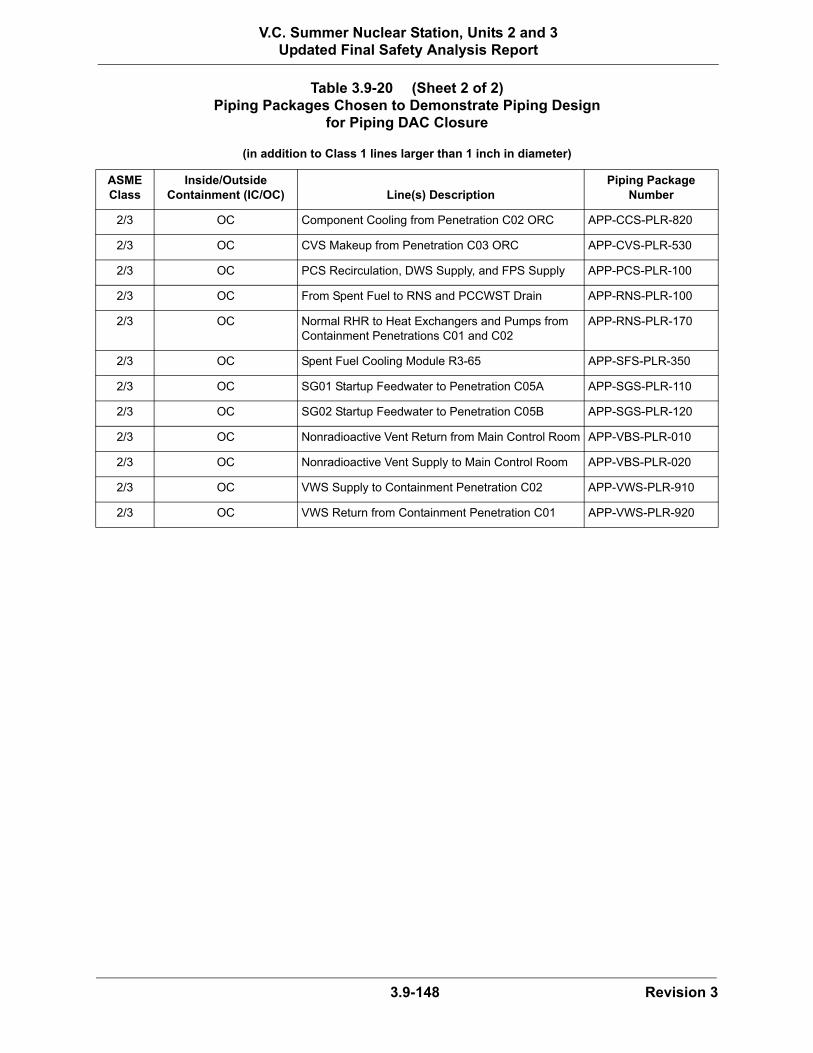
3.9-148 Revision 3
V.C. Summer Nuclear Station, Units 2 and 3Updated Final Safety Analysis Report
2/3 OC Component Cooling from Penetration C02 ORC APP-CCS-PLR-820
2/3 OC CVS Makeup from Penetration C03 ORC APP-CVS-PLR-530
2/3 OC PCS Recirculation, DWS Supply, and FPS Supply APP-PCS-PLR-100
2/3 OC From Spent Fuel to RNS and PCCWST Drain APP-RNS-PLR-100
2/3 OC Normal RHR to Heat Exchangers and Pumps from Containment Penetrations C01 and C02
APP-RNS-PLR-170
2/3 OC Spent Fuel Cooling Module R3-65 APP-SFS-PLR-350
2/3 OC SG01 Startup Feedwater to Penetration C05A APP-SGS-PLR-110
2/3 OC SG02 Startup Feedwater to Penetration C05B APP-SGS-PLR-120
2/3 OC Nonradioactive Vent Return from Main Control Room APP-VBS-PLR-010
2/3 OC Nonradioactive Vent Supply to Main Control Room APP-VBS-PLR-020
2/3 OC VWS Supply to Containment Penetration C02 APP-VWS-PLR-910
2/3 OC VWS Return from Containment Penetration C01 APP-VWS-PLR-920
Table 3.9-20 (Sheet 2 of 2)Piping Packages Chosen to Demonstrate Piping Design
for Piping DAC Closure
(in addition to Class 1 lines larger than 1 inch in diameter)
ASME Class
Inside/Outside Containment (IC/OC) Line(s) Description
Piping Package Number

3.9-149 Revision 3
V.C. Summer Nuclear Station, Units 2 and 3Updated Final Safety Analysis Report
(1) These snubbers are on the upper lateral support assembly of the steam generators.
Table 3.9-201 Safety Related Snubbers
System Snubber (Hanger) No. Line # System Snubber (Hanger) No. Line #
CVS APP-CVS-PH-11Y0164 L001 RNS APP-RNS-PH-12Y2060 L006
PXS APP-PXS-PH-11Y0020 L021A SGS APP-SGS-PH-11Y0001 L003B
RCS APP-RCS-PH-11Y0039 L215 SGS APP-SGS-PH-11Y0002 L003B
RCS APP-RCS-PH-11Y0067 L005B SGS APP-SGS-PH-11Y0004 L003B
RCS APP-RCS-PH-11Y0080 L112 SGS APP-SGS-PH-11Y0057 L003A
RCS APP-RCS-PH-11Y0081 L215 SGS APP-SGS-PH-11Y0058 L004B
RCS APP-RCS-PH-11Y0082 L112 SGS APP-SGS-PH-11Y0063 L003A
RCS APP-RCS-PH-11Y0090 L118A SGS APP-SGS-PH-11Y0065 L005B
RCS APP-RCS-PH-11Y0099 L022B SGS APP-SGS-PH-12Y0136 L015C
RCS APP-RCS-PH-11Y0103 L003 SGS APP-SGS-PH-12Y0137 L015C
RCS APP-RCS-PH-11Y0105 L003 SGS APP-SGS-PH-11Y0470 L006B
RCS APP-RCS-PH-11Y0112 L032A SGS APP-SGS-PH-11Y2002 L006A
RCS APP-RCS-PH-11Y0429 L225B SGS APP-SGS-PH-11Y2021 L006A
RCS APP-RCS-PH-11Y0528 L005A SGS APP-SGS-PH-11Y3101 L006B
RCS APP-RCS-PH-11Y0539 L225C SGS APP-SGS-PH-11Y3102 L006B
RCS APP-RCS-PH-11Y0550 L011B SGS APP-SGS-PH-11Y3121 L006B
RCS APP-RCS-PH-11Y0551 L011A SGS APP-SGS-PH-11Y0463 L006A
RCS APP-RCS-PH-11Y0553 L153B SGS APP-SGS-PH-11Y0464 L006A
RCS APP-RCS-PH-11Y0555 L153A SGS SG 1 Snubber A (1A) (1)
RCS APP-RCS-PH-11Y2005 L022A SGS SG 1 Snubber B (1B) (1)
RCS APP-RCS-PH-11Y2101 L032B SGS SG 2 Snubber A (2A) (1)
RCS APP-RCS-PH-11Y2117 L225A SGS SG 2 Snubber B (2B) (1)

3.9-150 Revision 3
V.C. Summer Nuclear Station, Units 2 and 3Updated Final Safety Analysis Report
Figures 3.9-1, 3.9-2, and 3.9-3 not used.

3.9-151 Revision 3
V.C. Summer Nuclear Station, Units 2 and 3Updated Final Safety Analysis Report
Figure 3.9-4 Control Rod Drive Mechanism

3.9-152 Revision 3
V.C. Summer Nuclear Station, Units 2 and 3Updated Final Safety Analysis Report
Figure 3.9-5 Lower Reactor Internals

3.9-153 Revision 3
V.C. Summer Nuclear Station, Units 2 and 3Updated Final Safety Analysis Report
Figure 3.9-6 Upper Core Support Structure

3.9-154 Revision 3
V.C. Summer Nuclear Station, Units 2 and 3Updated Final Safety Analysis Report
Figure 3.9-7 Integrated Head Package

3.9-155 Revision 3
V.C. Summer Nuclear Station, Units 2 and 3Updated Final Safety Analysis Report
Figure 3.9-8 Reactor Internals Interface Arrangement

3.9-156 Revision 3
V.C. Summer Nuclear Station, Units 2 and 3Updated Final Safety Analysis Report
Figure 3.9-9 Flow Skirt Schematic