Embed Size (px)
Citation preview

Issue 1 Print 2 LT–IXFMR38I–1
Page 1 of 16� Charles Industries, Ltd. All rights reserved. Printed in the United States of America.
INSTALLATION INSTRUCTIONS & OWNER’S MANUAL
Model 93–IXFMR3/8I–A
Marine Group
3.8I KVA InternationalUniversal IsoTransformerSHORELINE ISOLATION TRANSFORMER

LT–IXFMR38I–1
2
Contents
INTRODUCING... THE 3.8I INTERNATIONAL UNIVERSAL ISOTRANSFORMER 3. . . . . . . . . . . . . . . . . . . . . . . . Warranty/Registration 3. . . . . . . . . . . . . . . . . . . . . . . . . . . . . . . . . . . . . . . . . . . . . . . . . . . . . . . . . . . . . . . . . . . . . . . . . Manual Purpose 3. . . . . . . . . . . . . . . . . . . . . . . . . . . . . . . . . . . . . . . . . . . . . . . . . . . . . . . . . . . . . . . . . . . . . . . . . . . . . .
APPLICATION 3. . . . . . . . . . . . . . . . . . . . . . . . . . . . . . . . . . . . . . . . . . . . . . . . . . . . . . . . . . . . . . . . . . . . . . . . . . . . . . . . . . . . IMPORTANT SAFETY INSTRUCTIONS 3. . . . . . . . . . . . . . . . . . . . . . . . . . . . . . . . . . . . . . . . . . . . . . . . . . . . . . . . . . . . .
Warnings 3. . . . . . . . . . . . . . . . . . . . . . . . . . . . . . . . . . . . . . . . . . . . . . . . . . . . . . . . . . . . . . . . . . . . . . . . . . . . . . . . . . . . Installation Precaution 4. . . . . . . . . . . . . . . . . . . . . . . . . . . . . . . . . . . . . . . . . . . . . . . . . . . . . . . . . . . . . . . . . . . . . . . . Environmental Precaution 4. . . . . . . . . . . . . . . . . . . . . . . . . . . . . . . . . . . . . . . . . . . . . . . . . . . . . . . . . . . . . . . . . . . . . Application Precaution 4. . . . . . . . . . . . . . . . . . . . . . . . . . . . . . . . . . . . . . . . . . . . . . . . . . . . . . . . . . . . . . . . . . . . . . . . Damaged Unit Precaution 4. . . . . . . . . . . . . . . . . . . . . . . . . . . . . . . . . . . . . . . . . . . . . . . . . . . . . . . . . . . . . . . . . . . . . Disassembly Precaution 4. . . . . . . . . . . . . . . . . . . . . . . . . . . . . . . . . . . . . . . . . . . . . . . . . . . . . . . . . . . . . . . . . . . . . .
INSTALLING THE ISOTRANSFORMER 5. . . . . . . . . . . . . . . . . . . . . . . . . . . . . . . . . . . . . . . . . . . . . . . . . . . . . . . . . . . . . Ratings and Connections 5. . . . . . . . . . . . . . . . . . . . . . . . . . . . . . . . . . . . . . . . . . . . . . . . . . . . . . . . . . . . . . . . . . . . . Choosing an Electrical Wiring Method 5. . . . . . . . . . . . . . . . . . . . . . . . . . . . . . . . . . . . . . . . . . . . . . . . . . . . . . . . . Wired as an Isolation Transformer 6. . . . . . . . . . . . . . . . . . . . . . . . . . . . . . . . . . . . . . . . . . . . . . . . . . . . . . . . . . . . . Wired as a Polarization Transformer 10. . . . . . . . . . . . . . . . . . . . . . . . . . . . . . . . . . . . . . . . . . . . . . . . . . . . . . . . . . Securing Covers 15. . . . . . . . . . . . . . . . . . . . . . . . . . . . . . . . . . . . . . . . . . . . . . . . . . . . . . . . . . . . . . . . . . . . . . . . . . . . . Applying Power 15. . . . . . . . . . . . . . . . . . . . . . . . . . . . . . . . . . . . . . . . . . . . . . . . . . . . . . . . . . . . . . . . . . . . . . . . . . . . .
OPERATING THE ISOTRANSFORMER 15. . . . . . . . . . . . . . . . . . . . . . . . . . . . . . . . . . . . . . . . . . . . . . . . . . . . . . . . . . . . Safety First 15. . . . . . . . . . . . . . . . . . . . . . . . . . . . . . . . . . . . . . . . . . . . . . . . . . . . . . . . . . . . . . . . . . . . . . . . . . . . . . . . . . Proper Operation 15. . . . . . . . . . . . . . . . . . . . . . . . . . . . . . . . . . . . . . . . . . . . . . . . . . . . . . . . . . . . . . . . . . . . . . . . . . . .
MAINTAINING THE ISOTRANSFORMER 15. . . . . . . . . . . . . . . . . . . . . . . . . . . . . . . . . . . . . . . . . . . . . . . . . . . . . . . . . . . TROUBLESHOOTING 15. . . . . . . . . . . . . . . . . . . . . . . . . . . . . . . . . . . . . . . . . . . . . . . . . . . . . . . . . . . . . . . . . . . . . . . . . . . . WARRANTY & CUSTOMER SERVICE 15. . . . . . . . . . . . . . . . . . . . . . . . . . . . . . . . . . . . . . . . . . . . . . . . . . . . . . . . . . . . .
Warranty 15. . . . . . . . . . . . . . . . . . . . . . . . . . . . . . . . . . . . . . . . . . . . . . . . . . . . . . . . . . . . . . . . . . . . . . . . . . . . . . . . . . . . Warranty Service and Repair 15. . . . . . . . . . . . . . . . . . . . . . . . . . . . . . . . . . . . . . . . . . . . . . . . . . . . . . . . . . . . . . . . . Customer Service 16. . . . . . . . . . . . . . . . . . . . . . . . . . . . . . . . . . . . . . . . . . . . . . . . . . . . . . . . . . . . . . . . . . . . . . . . . . . .
SPECIFICATIONS 16. . . . . . . . . . . . . . . . . . . . . . . . . . . . . . . . . . . . . . . . . . . . . . . . . . . . . . . . . . . . . . . . . . . . . . . . . . . . . . .

LT–IXFMR38I–1
3� Charles Industries, Ltd. All rights reserved. Printed in the United States of America.
INTRODUCING... THE 3.8I INTERNATIONAL UNIVERSAL ISOTRANSFORMER �
Thank you for purchasing the IsoTransformer�! Your IsoTransformer completely isolates input power from outputpower providing an improved degree of safety and reducing galvanic current corrosion due to the direct connec-tion to AC shore power.
Warranty/Registration
Before proceeding, complete and mail back the Warranty Registration card.
Manual Purpose
With your personal safety in mind, this manual lists important safety precautions first, then covers installation,operation, maintenance, troubleshooting, warranty, and customer service information.
APPLICATION
The 3.8I KVA International Universal IsoTransformer is a shoreline isolation transformer intended for boats with30 amp/120 volt or 16 amp/240 volt service. The unit will operate on either 50 or 60 Hz and provides easyadaptation to European electrical systems. Properly installed, the IsoTranformer will electrically isolate AC shorepower from the boat’s AC power system, reducing galvanic current corrosion due to the AC shore power connec-tion.
The boat’s electrical system and grounding conductor are not actually connected to the shoreside system whenyou use the 3.8I KVA International Universal IsoTransformer as an isolation transformer. Power is transferredfrom the shoreside electrical system to the boat’s electrical system by magnetic coupling. This means there is nodirect electrical connection between the earth-grounded shore AC power and boat AC power systems. The shoregrounding conductor is connected to a shield that is wound between the primary (shore) and secondary (boat)transformer windings. This shield assures isolation on the boat by providing a protective layer between primaryand secondary windings within the transformer. In the unlikely event of a breakdown within the transformer, theshield can withstand the fault current of a properly sized shore supply circuit breaker long enough for the breakerto trip. In addition, by grounding one leg of the transformer secondary (X2) on board the boat, a “neutral” groundis established for the vessel’s electrical system. When using the transformer, shoreline polarity is no longer a con-sideration and a shoreline polarity device is not necessary.
IMPORTANT SAFETY INSTRUCTIONS
SAVE THESE INSTRUCTIONS. This manual contains important safety and operating instructionsfor the IsoTransformer. Read the entire manual before usage. Also read all instructions and cautions for andon the IsoTransformer.
Warnings
To avoid serious injury or death from high voltage electrical shock disconnect AC shore power beforeopening panel.
WARNING — HIGH VOLTAGE
Primary and secondary overcurrent protection and conductor sizing must be in accordance withmanufacturer's installation instructions.
WARNING — FIRE HAZARD
On board and in�water shock hazard. Transformer must be connected in accordance withmanufacturer's installation instructions.
WARNING

LT–IXFMR38I–1
4 � Charles Industries, Ltd. All rights reserved. Printed in the United States of America.
Do not store equipment on or next to transformer. This unit is designed to operate hot and must havefree air flow to prevent over heating or charring of adjacent material.
WARNING — FIRE HAZARD
Cord grip connectors must be used to prevent wires from chafing on the metal case and causing anelectrical short. See installation instructions for suitable connector types or call Charles MarineProducts to order a connector kit.
WARNING — ELECTRICAL SHOCK AND FIRE HAZARD
Installation Precaution
Boat wiring is a complex task that can cause shock, corrosion and other hazards if not done properly by trained,experienced personnel. For more information on this subject contact the American Boat and Yacht Council(ABYC) or see the standards and regulations below:
American Boat and Yacht Council 3069 Solomon’s Island RoadE-8 “Alternating Current (AC) Electrical Systems on Boats” Edgewater, MD 21037
Telephone: 410.956.1050FAX: 410.456.2737
NFPA Standard 302. National Fire Protection Association
“Pleasure and Commercial Motor Craft” 1 Batterymarch ParkP.O. Box 9101Quincy, MA 02269-9401
Telephone: 800.344.3555
Rules and Regulations for Recreational Boats. Excerpts from the United States Code (USC) and the Code ofFederal Regulations (CFR) (U.S. Coast Guard Regulations) are available from the American Boat and YachtCouncil listed above.
Note: Installation of the IsoTransformer must be made in accordance with all applicable standards and regula-tions.
Environmental Precaution
The IsoTransformer is intended for installation inside an engine room or elsewhere inside the boat. Make surethat the location will not subject the unit to rain, snow, excessive moisture, or excessive heat.
This device is ignition protected in accordance with U.S. Coast Guard regulations under 33 CFR183.410.
NOTICE
Application Precaution
These units are intended for hard-wired, permanent, on-board applications. Use of attachments not recom-mended or sold by Charles Marine Products may result in risk of fire, electrical shock or personal injury.
Damaged Unit Precaution
Do not operate the IsoTransformer if it has received a sharp blow, been dropped, immersed in water or otherwisedamaged. See the section in this manual on Warranty & Customer Service for repair information.
Disassembly Precaution
Do not disassemble the IsoTransformer. See the sections in this manual on Maintaining the IsoTransformer, Trou-bleshooting the IsoTransformer and Warranty & Customer Service.

LT–IXFMR38I–1
5� Charles Industries, Ltd. All rights reserved. Printed in the United States of America.
INSTALLING THE ISOTRANSFORMER
Ratings and Connections
The 3.8I KVA International Universal IsoTransformer is designed for 120 or 240 volt input, 120, 120/240 (3 wire)or 240 volt output and 50 or 60 Hz operation in order to provide maximum flexibility in a multitude of applications.Both the primary (input) and secondary (output) windings may be reconnected for various voltages as shown be-low. The unit is rated at 3.8 KVA in order to be compatible with 16 ampere, 50 Hz European dockside powersources.The following diagrams do not include all variations of the IsoTransformer. Contact Charles Marine Products foradditional information.
PrimaryVolts
Primary LineConnections Interconnect
240
120
H1–H4
H1–H4
H2 to H3
SecondaryVolts
Secondary LineConnections Interconnect
240
120/240
X1–X4
X1–X3–X4
X2 to X3
X2 to X3
120 X1–X4 X1 to X3X2 to X4
H1 to H3H2 to H4
H1
H4
SH GND
X4
X1
X2
X3
H3
H2
Figure 1. Schematic and Connections
Choosing an Electrical Wiring Method
There are two wiring methods that can be used to install the IsoTransformer as an isolation transformer in accor-dance with ABYC E-8 Alternating Current (AC) Electrical Systems on Boats. A third method, also in accordancewith ABYC E-8, can be used to install the IsoTransformer as a polarization transformer if desired. The third meth-od is not preferred, because wiring the unit in the manner described circumvents the AC grounding conductorisolation between shore and boat power and may require the use of a galvanic isolator to reduce galvanic corro-sion.
Note: Figure 2 through Figure 7 are reprinted with permission from the American Boat and Yacht Council(ABYC). To obtain the complete standard referenced or any other standards contact:
American Boat and Yacht Council: 3069 Solomon’s Island RoadEdgewater, MD 21037Telephone: 410.956.1050FAX: 410.456.2737

LT–IXFMR38I–1
6 � Charles Industries, Ltd. All rights reserved. Printed in the United States of America.
Wired as an Isolation Transformer
The only difference between Method 1 and Method 2 is that in Method 2, a Ground Fault Protector (GFP) mustbe used instead of just a circuit breaker, and the shore grounding conductor is not wired past the inlet of the boat.Method 1 is most commonly used.
Note: This diagram does not illustrate a complete system. Refer to the appropriate ABYC text.
Isolation Transformer System with Single-Phase 120-Volt Input with Grounded Secondary. ShieldGrounded on Shore. Metal Case Grounded on the Boat. The green grounding wire from the shoreinlet is connected to the isolation transformer shield. The green grounding wire is connected to theshell of the power inlet which is insulated from the hull of the boat.
The ungrounded and grounded shore current-carrying conductors are connected from the power inletto the primary winding of the isolation transformer through an overcurrent protection device which si-multaneously opens both current-carrying shore conductors. Fuses shall not be used in lieu of thesimultaneous trip devices.
120-Volt branch circuit breakers are permitted to use single-pole breakers in the ungrounded current-carrying conductors.
The secondary of the isolation transformer is grounded (polarized) on the boat.
The boat grounding system (green) conductor is connected from the metal case of the isolation trans-former to all noncurrent-carrying parts of the boat’s AC electrical system including the engine negativeterminal or its bus without interposing switches or overcurrent protection devices.
ÉÉÉÉÉÉÉÉÉÉÉÉ
Ung
roun
ded
Con
duct
or (
Bla
ck)
Gro
unde
d N
eutr
al C
ondu
ctor
(W
hite
)
Gro
undi
ng C
ondu
ctor
(G
reen
)
Shore Connection
Shore Power Cable
Shore Power Cable Connector
2-Pole, 3-Wire Grounding Type Plugs & Receptacles
Sho
re S
ide
Boa
t Sid
e
Power Inlet(Electrically insulatedfrom the Boat)
Main Shore PowerDisconnectCircuit Breaker
Transformer Case
Encapsulated Single PhaseIsolation Transformer
To Engine NegativeTerminal or its Bus
Bla
ck
Whi
te
Gre
en
120 VACGroundingTypeReceptacle
120 VACDevice
BranchCircuitBreaker(Typical)
Transformer Shield(Insulated from Case and Core)
Transformer CaseGround Connection
Figure 2. Electrical Diagram – Method 1 (see Figure 8 for Wiring Connections)
LT–IXFMR38I–1
7� Charles Industries, Ltd. All rights reserved. Printed in the United States of America.
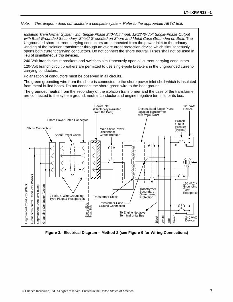
Note: This diagram does not illustrate a complete system. Refer to the appropriate ABYC text.
Isolation Transformer System with Single-Phase 240-Volt Input, 120/240-Volt Single-Phase Outputwith Boat Grounded Secondary. Shield Grounded on Shore and Metal Case Grounded on Boat. TheUngrounded shore current-carrying conductors are connected from the power inlet to the primarywinding of the isolation transformer through an overcurrent protection device which simultaneouslyopens both current carrying conductors. Do not connect the shore neutral. Fuses shall not be used inlieu of simultaneous trip devices.
240-Volt branch circuit breakers and switches simultaneously open all current-carrying conductors.120-Volt branch circuit breakers are permitted to use single-pole breakers in the ungrounded current-carrying conductors.
Polarization of conductors must be observed in all circuits.The green grounding wire from the shore is connected to the shore power inlet shell which is insulatedfrom metal-hulled boats. Do not connect the shore green wire to the boat ground.
The grounded neutral from the secondary of the isolation transformer and the case of the transformerare connected to the system ground, neutral conductor and engine negative terminal or its bus.
ÉÉÉÉÉÉÉÉÉÉÉÉÉÉÉÉ
Ung
roun
ded
Con
duct
or (
Red
)
Gro
unde
d N
eutr
al C
ondu
ctor
(W
hite
)
Gro
undi
ng C
ondu
ctor
(G
reen
)
Shore Connection
Shore Power Cable
Shore Power Cable Connector
3-Pole, 4-Wire GroundingType Plugs & Receptacles
Sho
re S
ide
Boa
t Sid
e
Power Inlet(Electrically insulatedfrom the Boat)
Main Shore PowerDisconnectCircuit Breaker
Encapsulated Single PhaseIsolation Transformer
To Engine NegativeTerminal or its Bus
Red
Whi
te
Gre
en
120 VACGroundingTypeReceptacle
120 VACDevice
BranchCircuitBreaker(Typical)
Transformer Shield
Transformer CaseGround Connection
Ung
roun
ded
Con
duct
or (
Bla
ck)
with Metal Case
Bla
ck 240 VACDevice
TransformerSecondaryOvercurrentProtection
Figure 3. Electrical Diagram – Method 2 (see Figure 9 for Wiring Connections)

LT–IXFMR38I–1
8 � Charles Industries, Ltd. All rights reserved. Printed in the United States of America.
Note: This diagram does not illustrate a complete system. Refer to the appropriate ABYC text.
Isolation Transformer System with Single-Phase 120-Volt Input with Ground Fault Protection andGrounded Secondary. Shield and Metal Case Grounded on the Boat. The green grounding wire fromthe shore inlet is not connected to the isolation transformer shield or metal case. The green groundingwire is connected to the shell of the power inlet which is insulated from the hull of the boat.The ungrounded and grounded shore current-carrying conductors are connected from the power inletto the primary winding of the isolation transformer through a ground fault protection device which si-multaneously opens both current-carrying shore conductors. Fuses shall not be used in lieu of thesimultaneous trip devices.
120-Volt branch circuit breakers are permitted to use single-pole breakers in the ungrounded current-carrying conductors.The secondary of the isolation transformer is grounded (polarized) on the boat.
The boat grounding system (green) conductor is connected from the shield and metal case of theisolation transformer to all noncurrent-carrying parts of the boat’s AC electrical system including theengine negative terminal or its bus without interposing switches or overcurrent protection devices.
ÉÉÉÉÉÉÉÉÉÉÉÉ
Ung
roun
ded
Con
duct
or (
Bla
ck)
Gro
unde
d N
eutr
al C
ondu
ctor
(W
hite
)
Gro
undi
ng C
ondu
ctor
(G
reen
)
Shore Connection
Shore Power Cable
Shore Power Cable Connector
2-Pole, 3-Wire Grounding Type Plugs & Receptacles
Sho
re S
ide
Boa
t Sid
e
Power Inlet(Electrically insulatedfrom the Boat)
Main Shore PowerDisconnectCircuit Breaker
Encapsulated Single PhaseIsolation Transformer
To Engine NegativeTerminal or its Bus
Bla
ck
Whi
te
Gre
en120 VACGroundingTypeReceptacle
120 VACDevice
BranchCircuitBreaker(Typical)
Transformer Shield
Transformer CaseGround Connection
with Off
with Metal Case
Figure 4. Electrical Diagram – Method 3 (see Figure 10 for Wiring Connections)
LT–IXFMR38I–1
9� Charles Industries, Ltd. All rights reserved. Printed in the United States of America.
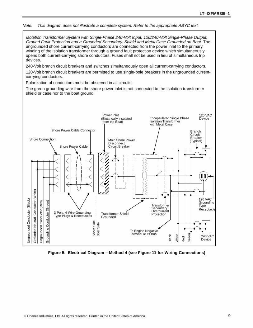
Note: This diagram does not illustrate a complete system. Refer to the appropriate ABYC text.
Isolation Transformer System with Single-Phase 240-Volt Input, 120/240-Volt Single-Phase Output,Ground Fault Protection and a Grounded Secondary. Shield and Metal Case Grounded on Boat. Theungrounded shore current-carrying conductors are connected from the power inlet to the primarywinding of the isolation transformer through a ground fault protection device which simultaneouslyopens both current-carrying shore conductors. Fuses shall not be used in lieu of simultaneous tripdevices.
240-Volt branch circuit breakers and switches simultaneously open all current-carrying conductors.120-Volt branch circuit breakers are permitted to use single-pole breakers in the ungrounded current-carrying conductors.
Polarization of conductors must be observed in all circuits.The green grounding wire from the shore power inlet is not connected to the Isolation transformershield or case nor to the boat ground.
ÉÉÉÉÉÉÉÉÉÉÉÉÉÉÉÉ
Ung
roun
ded
Con
duct
or (
Red
)
Gro
unde
d N
eutr
al C
ondu
ctor
(W
hite
)
Gro
undi
ng C
ondu
ctor
(G
reen
)
Shore Connection
Shore Power Cable
Shore Power Cable Connector
3-Pole, 4-Wire GroundingType Plugs & Receptacles
Sho
re S
ide
Boa
t Sid
e
Power Inlet(Electrically insulatedfrom the Boat)
Main Shore PowerDisconnectCircuit Breaker
Encapsulated Single PhaseIsolation Transformer
To Engine NegativeTerminal or its Bus
Red
Whi
te
Gre
en
120 VACGroundingTypeReceptacle
120 VACDevice
BranchCircuitBreaker(Typical)
Transformer Shield
Ung
roun
ded
Con
duct
or (
Bla
ck)
with Metal Case
Bla
ck 240 VACDevice
TransformerSecondaryOvercurrentProtection
Grounded
Figure 5. Electrical Diagram – Method 4 (see Figure 11 for Wiring Connections)

LT–IXFMR38I–1
10 � Charles Industries, Ltd. All rights reserved. Printed in the United States of America.
Wired as a Polarization Transformer
In this method the shield and the shore grounding conductor are wired directly to the transformer neutral (X2) andcase ground (GND). An optional galvanic isolator is also shown in-line with the shoreline grounding wire.
Note: This diagram does not illustrate a complete system. Refer to the appropriate ABYC text.
Single-Phase 120-Volt Polarization Transformer System with Grounded Secondary, and Grounding(green) Conductor. The grounded and ungrounded shore current-carrying conductors are connectedfrom the power inlet to the primary winding of the polarization transformer through an overcurrentprotection device which simultaneously opens both current-carrying shore conductors. Fuses shall notbe used in lieu of the simultaneous trip devices.
120-Volt branch circuit breakers are permitted to use single-pole breakers in the ungrounded current-carrying conductors.The shore grounding (green) conductor is connected from the shore power cable and the boat’s pow-er inlet directly to all non-current-carrying parts of the AC electrical system including the transformercase and shield and to the engine terminal or its bus without interposing switches or overcurrentprotection devices.
One current-carrying conductor of the transformer secondary is grounded on the boat and is desig-nated as neutral.
ÉÉÉÉÉÉÉÉÉÉÉÉ
Ung
roun
ded
Con
duct
or (
Bla
ck)
Gro
unde
d N
eutr
al C
ondu
ctor
(W
hite
)
Gro
undi
ng C
ondu
ctor
(G
reen
)
Shore Connection
Shore Power Cable
Shore Power Cable Connector
2-Pole, 3-Wire Grounding Type Plugs & Receptacles
Sho
re S
ide
Boa
t Sid
e
Power Inlet(Electrically insulatedfrom the Boat if an
Main Shore PowerDisconnectCircuit Breaker
Transformer Case
Encapsulated Single PhasePolarization Transformer with
To Engine NegativeTerminal or its Bus
Bla
ck
Whi
te
Gre
en
120 VACGroundingTypeReceptacle
120 VACDevice
BranchCircuitBreaker(Typical)
Transformer CaseGround Connection
Isolator is Installed)
OptionalGalvanicIsolator
Metal Case
Charles Marine Products Note: Shield to be connected to case ground on IsoTransformer
Figure 6. Electrical Diagram – Method 1 (see Figure 12 for Wiring Connections)

LT–IXFMR38I–1
11� Charles Industries, Ltd. All rights reserved. Printed in the United States of America.
Note: This diagram does not illustrate a complete system. Refer to the appropriate ABYC text.
Single-Phase 240-Volt Input, 120/240-Volt Single-Phase Output Polarization Transformer System withShore Grounding (Green) Conductor. The ungrounded shore current-carrying conductors are con-nected from the power inlet to the primary winding of the polarization transformer through an overcur-rent protection device which simultaneously opens both current carrying shore conductors. Fusesshall not be used in lieu of simultaneous trip devices.
240-Volt branch circuit breakers and switches simultaneously open all current-carrying conductors.
120-Volt branch circuit breakers are permitted to use single-pole breakers in the ungrounded current-carrying conductors.
The shore grounded (green) conductor is connected from the shore power cable and the boat’s powerinlet directly to all non-current-carrying parts of the AC electrical system including the transformercase and to the engine terminal or its bus without interposing switches or overcurrent protection de-vices.
ÉÉÉÉÉÉÉÉÉÉÉÉÉÉÉÉ
Ung
roun
ded
Con
duct
or (
Red
)
Gro
unde
d N
eutr
al C
ondu
ctor
(W
hite
)
Gro
undi
ng C
ondu
ctor
(G
reen
)
Shore Connection
Shore Power Cable
Shore Power Cable Connector
3-Pole, 4-Wire GroundingType Plugs & Receptacles
Sho
re S
ide
Boa
t Sid
e
Power Inlet(Electrically insulatedfrom the Boat if
Main Shore PowerDisconnectCircuit Breaker
Encapsulated Single PhasePolarization Transformer
To Engine NegativeTerminal or its Bus
Red
Whi
te
Gre
en
120 VACGroundingTypeReceptacle
120 VACDevice
BranchCircuitBreaker(Typical)
Transformer CaseGround Connection
Ung
roun
ded
Con
duct
or (
Bla
ck)
with Metal Case
Bla
ck 240 VACDevice
TransformerSecondaryOvercurrentProtection
isolator installed)
Charles Marine Products Note: Shield to be connected to case ground on IsoTransformer
Figure 7. Electrical Diagram – Method 2 (see Figure 13 for Wiring Connections)
LT–IXFMR38I–1
12 � Charles Industries, Ltd. All rights reserved. Printed in the United States of America.
H4
GND
OUTPUT
X1
X2
X3
X4
H1
H2
SH
INPUT
H3
BLU/WHT
BLUE
RED
ORANGE
GREEN
YELLOW
BLACK
BROWN
WHITE
GRAY
GREEN (Shore Grounding)
BLACK (Line)WHITE (Neutral)
WHITE (Neutral)BLACK (Line)
GREEN (Boat Grounding)
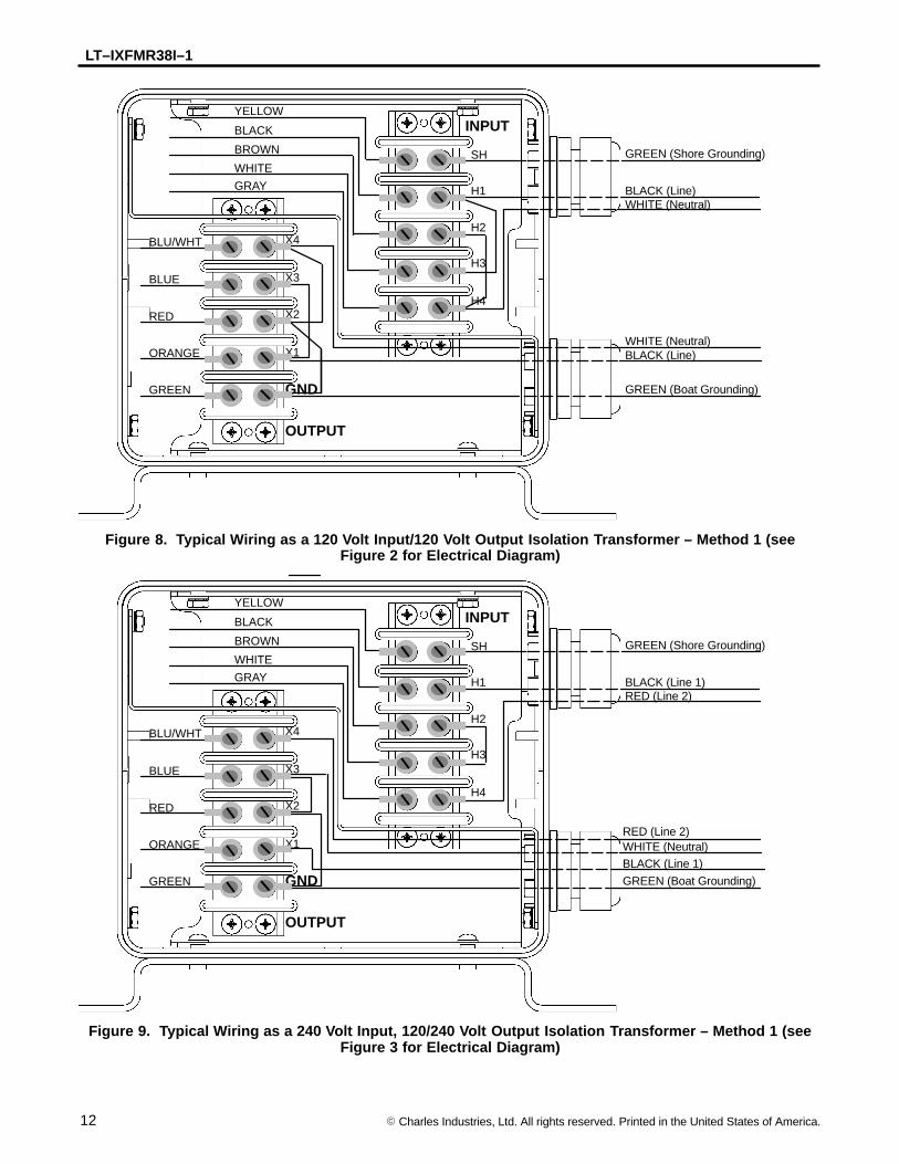
Figure 8. Typical Wiring as a 120 Volt Input/120 Volt Output Isolation Transformer – Method 1 (seeFigure 2 for Electrical Diagram)
H4
GND
OUTPUT
X1
X2
X3
X4
H1
H2
SH
INPUT
H3
BLU/WHT
BLUE
RED
ORANGE
GREEN
YELLOW
BLACK
BROWN
WHITE
GRAY
GREEN (Shore Grounding)
BLACK (Line 1)RED (Line 2)
WHITE (Neutral)BLACK (Line 1)
GREEN (Boat Grounding)
RED (Line 2)
Figure 9. Typical Wiring as a 240 Volt Input, 120/240 Volt Output Isolation Transformer – Method 1 (seeFigure 3 for Electrical Diagram)
LT–IXFMR38I–1
13� Charles Industries, Ltd. All rights reserved. Printed in the United States of America.
H4
GND
OUTPUT
X1
X2
X3
X4
H1
H2
SH
INPUT
H3
BLU/WHT
BLUE
RED
ORANGE
GREEN
YELLOW
BLACK
BROWN
WHITE
GRAY BLACK (Line)WHITE (Neutral)
WHITE (Neutral)BLACK (Line)
GREEN (Boat Grounding)
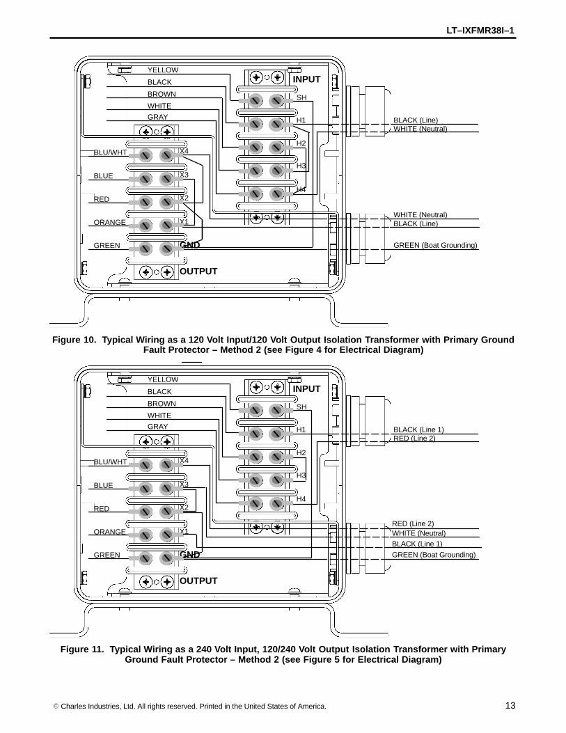
Figure 10. Typical Wiring as a 120 Volt Input/120 Volt Output Isolation Transformer with Primary GroundFault Protector – Method 2 (see Figure 4 for Electrical Diagram)
H4
GND
OUTPUT
X1
X2
X3
X4
H1
H2
SH
INPUT
H3
BLU/WHT
BLUE
RED
ORANGE
GREEN
YELLOW
BLACK
BROWN
WHITE
GRAY BLACK (Line 1)RED (Line 2)
WHITE (Neutral)BLACK (Line 1)
GREEN (Boat Grounding)
RED (Line 2)
Figure 11. Typical Wiring as a 240 Volt Input, 120/240 Volt Output Isolation Transformer with PrimaryGround Fault Protector – Method 2 (see Figure 5 for Electrical Diagram)
LT–IXFMR38I–1
14 � Charles Industries, Ltd. All rights reserved. Printed in the United States of America.
H4
GND
OUTPUT
X1
X2
X3
X4
H1
H2
SH
INPUT
H3
BLU/WHT
BLUE
RED
ORANGE
GREEN
YELLOW
BLACK
BROWN
WHITE
GRAY
GREEN (Shore Grounding)
BLACK (Line)WHITE (Neutral)
WHITE (Neutral)BLACK (Line)
GREEN (Boat Grounding)
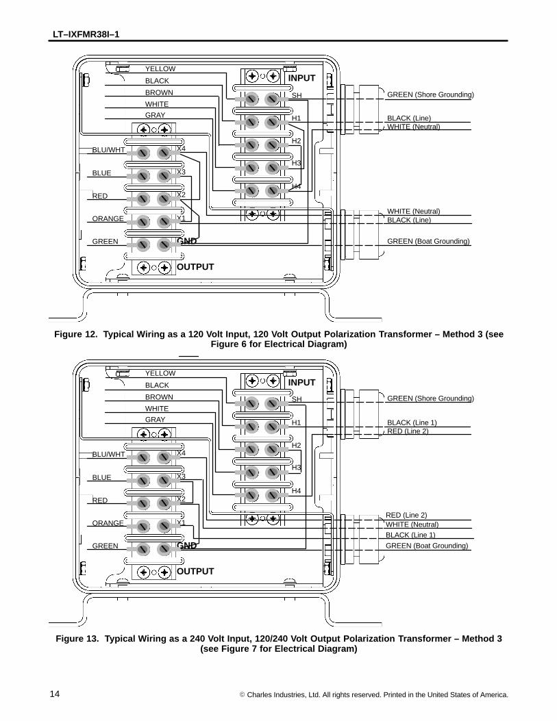
Figure 12. Typical Wiring as a 120 Volt Input, 120 Volt Output Polarization Transformer – Method 3 (seeFigure 6 for Electrical Diagram)
H4
GND
OUTPUT
X1
X2
X3
X4
H1
H2
SH
INPUT
H3
BLU/WHT
BLUE
RED
ORANGE
GREEN
YELLOW
BLACK
BROWN
WHITE
GRAY
GREEN (Shore Grounding)
BLACK (Line 1)RED (Line 2)
WHITE (Neutral)BLACK (Line 1)
GREEN (Boat Grounding)
RED (Line 2)
Figure 13. Typical Wiring as a 240 Volt Input, 120/240 Volt Output Polarization Transformer – Method 3(see Figure 7 for Electrical Diagram)
LT–IXFMR38I–1
15� Charles Industries, Ltd. All rights reserved. Printed in the United States of America.
Securing Covers
After all connections and terminations have been made, the access cover should be re-installed using all hard-ware supplied.
Applying Power
Power should only be applied after all connections and terminations have been made and the access cover issecure. Plug in the shore power and turn on the appropriate circuit breakers to apply power. Refer to the sectionon Proper Operation.
OPERATING THE ISOTRANSFORMER
Safety First
Follow all precautions in the IMPORTANT SAFETY INSTRUCTIONS section in this manual. Pay close attentionto the DANGER, WARNING and CAUTION boxes both within this manual and labeled on the unit.
Proper Operation
When properly installed and connected, the IsoTransformer will provide isolation between shore and boat powerwhile maintaining a one to one turns ratio (shore voltage equals boat voltage).
MAINTAINING THE ISOTRANSFORMER
To avoid serious injury or death from high voltage electrical shock, disconnect the AC shore powerbefore attempting any maintenance or cleaning.
WARNING – HIGH VOLTAGE
No adjustment or maintenance is required for the IsoTransformer other than periodic cleaning of the outside cabi-net with a dry cloth and inspecting all connections for tightness and corrosion by a qualified service person.
TROUBLESHOOTING
If there is a problem with the IsoTransformer, first check that all connections are accurate and secure, and retest.If all connections are good, contact Charles Marine Products for technical assistance.
WARRANTY & CUSTOMER SERVICE
Warranty
CHARLES MARINE PRODUCTS warrants the IsoTransformer will be free from defects in materials and work-manship which cause mechanical failure for one (1) year, as set forth in the Limited Warranty. Review this warran-ty carefully for information on what is covered by its terms. Complete and return the warranty registration cardwithin ten (10) days of purchase to establish proof of ownership and validate the warranty coverage. You mustprovide notice of any alleged defect in material or workmanship within thirty (30) days of discovering the problem,and within the warranty period. Follow the procedure outlined below to obtain warranty service.
Warranty Service and Repair
If the unit fails to operate properly after following all the instructions in the manual, or if the unit requires service,take the following steps.
1. Return the unit to:
Charles Industries, Ltd.400 S.E. 8th StreetCasey, IL 62420
ATTN: Service Center
LT–IXFMR38I–1
16 � Charles Industries, Ltd. All rights reserved. Printed in the United States of America.
Note: Shipping costs to and from the service center are your responsibility.
2. Include a letter with your company name (if applicable), contact, return address, daytime phone num-ber and the nature of the failure.
3. When service is complete, Charles Industries, Ltd. will return the unit to you. If there are any repaircharges, a representative from Charles Industries will contact you with that information prior to havingthe unit repaired.
Customer Service
If technical assistance or customer service is needed, contact Charles Marine Products at:847/806-6300 (Customer Service)847/806-6231 (FAX)
For correspondence only, mail to:Charles Marine ProductsCharles Center5600 Apollo DriveRolling Meadows, IL 60008-4049
SPECIFICATIONS
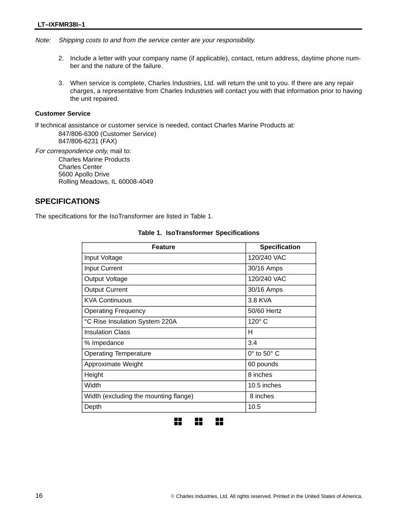
The specifications for the IsoTransformer are listed in Table 1.
Table 1. IsoTransformer Specifications
Feature Specification
Input Voltage 120/240 VAC
Input Current 30/16 Amps
Output Voltage 120/240 VAC
Output Current 30/16 Amps
KVA Continuous 3.8 KVA
Operating Frequency 50/60 Hertz
°C Rise Insulation System 220A 120° C
Insulation Class H
% Impedance 3.4
Operating Temperature 0° to 50° C
Approximate Weight 60 pounds
Height 8 inches
Width 10.5 inches
Width (excluding the mounting flange) 8 inches
Depth 10.5
� � �