Embed Size (px)
Citation preview

CHAPTER
6Profile Viewsand Profiles
INTRODUCTION
Road design’s second step views an alignment from its side, showing the elevations alongits path. In Civil 3D, a profile view is a grid that displays and annotates a profile’s stationsand elevations. A profile is the elevations from a surface or line work representing a road-way’s vertical design within a profile view. Civil 3D dynamically links the profile view(grid) and the surface profiles to the alignment. If you are editing the alignment (move,shorten, or lengthen), the profile view and the surface profiles change to show the modi-fied alignment’s length and elevations. Changing a surface causes its profile to changewithin a profile view. The vertical design unaffected by a changing alignment will needadjustment after changing an alignment’s geometry.
Styles affect the grid format, the grid annotation and types, profiles, and their displayproperties. A complicated web of dependencies and styles makes up the final profileview and its profiles.
OBJECTIVES
This chapter focuses on the following topics:
• Introducing and Creating a Profile Grid
• Creating a Simple Profile Grid Style and Modifying Existing Grid Styles
• Introducing and Creating a Profile
• Creating a Simple Profile Style and Modifying Existing Grid Styles
OVERVIEWThis chapter covers roadway design’s second phase, profile view and profiles. A pro-file view is a graph that represents an alignment’s stationing and elevations along thatalignment’s path. A profile is line work within a profile view that represents surfaceelevations along an alignment’s path or a proposed roadway’s vertical design. A profileview and its surface profiles are the backdrop for the proposed roadway verticaldesign.
234
© 2011 Delmar, Cengage Learning. All Rights Reserved. May not be scanned, copied or duplicated, or posted to a publicly accessible website, in whole or in part.

It is in the profile view that you start developing a feel for a road design’s impact onearthworks volumes. The proposed roadway’s height above or below existing ground’selevations begins by giving visual feedback as to amounts of earthwork or what pro-blems need to be resolved to build the road (see Figure 6.1).
There are three steps to creating a profile and profile view. First, there must be data;an alignment and its profile data which can be a surface or a file containing alignmentstations and their elevations. The second step is creating the profile (sampling surfaceelevations, assigning styles, and adjusting other values), and the last step, if you choseto do so, is immediately creating a profile view containing the profile(s).
Profile and Profile View steps:
1. Have an alignment and a surface or read profile data from a file
2. Create a Profile
3. Create a Profile View
A profile view can contain multiple profiles (surfaces and proposed vertical designs).Each profile can have a different style, thus allowing it to display its informationuniquely in the profile view.
Unit 1AProfile View is a graph in which profiles are drawn. A profile represents the existingground, subsurfaces, or one or more proposed vertical designs. The styles that affect aprofile view and its profiles are the focus of this first unit.
Unit 2The second unit of this chapter reviews the steps needed to create a profile and itsProfile View.
Unit 3Within a profile view and an existing ground profile, a designer creates a vertical(alignment) roadway design. A vertical alignment contains tangents and vertical
Surface(s)
AlignmentsHorizontalRoadwayAlignment
ProfilesVerticalRoadwayAlignment
Roadway Volumes
CreateAssembly
Cross SectionsCorridor
FIGURE 6.1
© 2011 Delmar, Cengage Learning. All Rights Reserved. May not be scanned, copied or duplicated, or posted to a publicly accessible website, in whole or in part.
Chap t e r 6 • Pr o f i l e V i ew s and P r o f i l e s 235

curves. Civil 3D has three vertical curves types: circular, symmetrical, and asymmetri-cal parabolic curves. Creating a vertical alignment is the topic of the third unit of thischapter.
Unit 4The analysis and editing of a vertical alignment (profile) is the focus of this chapter’sfourth unit. This unit reviews a vertical alignment using Toolbox reports, the InquiryTools, profile properties, and vistas within the vertical editor.
Unit 5The fifth unit of this chapter reviews profile and vertical alignment annotation andprojecting 3D objects to a profile view. The annotation is the result of label sets ap-plied when a profile is created or is the result of labels that are added after the profile iscreated.
UNIT 1: PROFILE VIEW AND PROFILE STYLES
A Profile View is a graph in which profiles exist. Profiles within a view represent ex-isting ground and other surfaces along an alignment and one or more proposed verti-cal designs.
PROFILE VIEWProfile View is a grid that represents alignment stations and elevations along its path.Stations are along the graph’s top or bottom and create vertical lines to mark the sta-tions in the profile view’s elevation area (see Figure 6.2). The station interval has amajor and minor increment with station annotation at the major stations (minimally).All values are user specified and set in the styles applied to the profile view.
Elevations are measured from a graph’s datum (lowest elevation) upward to the high-est elevation. The line interval is an even elevation (every 2 or 5 feet, for example) andhas secondary tick marks at minor increments with annotation at major elevations(minimally). All values are user-specified values set in the styles applied to the profileview.
FIGURE 6.2
© 2011 Delmar, Cengage Learning. All Rights Reserved. May not be scanned, copied or duplicated, or posted to a publicly accessible website, in whole or in part.
236 Harn e s s i n g Au t oCAD Civ i l 3D 2011

Traditionally a profile view is 1/10th of the horizontal scale. If you are working with adrawing that has a 1 00 ¼ 40 0 scale, the vertical scale is 1 00 ¼ 4 0 (1 inch of paper repre-sents 4 feet of relief).
PROFILE VIEW STYLE — FULL GRIDA Profile View Style defines values that affect titles and defines station and elevationannotation. A Profile View Style is a multi-tabbed dialog box with each tab affectingdifferent aspects of the view.
InformationAs with all styles, there is an Information tab. This tab contains the name, descrip-tion, and details on who created or modified the style as well as when that style wascreated or modified.
GraphThe Graph tab affects the vertical scale and profile view direction (see Figure 6.3).The panel’s top half lists the current vertical and horizontal scales, and the amountof vertical exaggeration. By default, a vertical scale is 1/10th of the horizontal scale.If the horizontal scale is 1 00 ¼ 40 0, then the vertical scale is 1 00 ¼ 4 0. The vertical scaleat the top left sets traditional scales and just below it, a user can set a custom scalevalue.
The panel’s lower half sets the profile view’s direction (left to right or right to left).
FIGURE 6.3
© 2011 Delmar, Cengage Learning. All Rights Reserved. May not be scanned, copied or duplicated, or posted to a publicly accessible website, in whole or in part.
Chap t e r 6 • Pr o f i l e V i ew s and P r o f i l e s 237

GridGrid’s top sets a view’s clipping parameters. There are four possible toggle combina-tions: all on; all off; clip horizontally; and clip vertically. The effect of toggling on allclip toggles is seen in the right side of Figure 6.4. The left side of Figure 6.4 showswhat occurs when all the toggles are off.
If you are toggling on only horizontal clipping, the right side of Figure 6.5 shows theresult. If you are toggling on only vertical clipping, the left side of Figure 6.5 showsthe result.
FIGURE 6.4
FIGURE 6.5
© 2011 Delmar, Cengage Learning. All Rights Reserved. May not be scanned, copied or duplicated, or posted to a publicly accessible website, in whole or in part.
238 Harn e s s i n g Au t oCAD Civ i l 3D 2011

The panel’s lower left sets the major grid padding around a grid. The panel’s lowerright sets an axis offset. When the axis offset has a positive value, a gap appears be-tween the axis and the grid lines (see Figure 6.6).
Title AnnotationThe panel’s left side sets the title’s content, text style, text size, and location (see Fig-ure 6.7). The title has a justification setting and a border toggle. The panel’s right sidesets the title text, justification, text style, size, and content, for each of the four axes.
FIGURE 6.7
FIGURE 6.6
© 2011 Delmar, Cengage Learning. All Rights Reserved. May not be scanned, copied or duplicated, or posted to a publicly accessible website, in whole or in part.
Chap t e r 6 • Pr o f i l e V i ew s and P r o f i l e s 239

Horizontal AxesHorizontal Axes defines major and minor station text and tick intervals, text stylesand size, and titles (see Figure 6.8). Station labeling can be at the top, bottom, orboth. The panel’s top toggles the settings for the grid’s top or bottom and if the firstgrid line is annotated. The rightmost column defines ticks that represent the horizon-tal geometry that is displayed in the view.
Vertical AxesVertical Axes defines the elevation annotation’s major and minor text and tick inter-vals and text styles, justification, rotation, and size (see Figure 6.9). Elevation labelingcan be at the right, left, or both. The panel’s top center toggles the side to which thesettings apply and whether the first elevation grid line has annotation.
FIGURE 6.8
© 2011 Delmar, Cengage Learning. All Rights Reserved. May not be scanned, copied or duplicated, or posted to a publicly accessible website, in whole or in part.
240 Harn e s s i n g Au t oCAD Civ i l 3D 2011

DisplayEven though a style defines the profile view axes’ annotation, the Display tab settingsdetermine what annotation the view style actually displays. The Display tab lists all ofthe view’s components, their layer, layer properties, and their visibility (see Figure6.10). Even though every possible tick, grid, or label is defined, they will show onlyif they are turned on in this panel.
FIGURE 6.9
FIGURE 6.10
© 2011 Delmar, Cengage Learning. All Rights Reserved. May not be scanned, copied or duplicated, or posted to a publicly accessible website, in whole or in part.
Chap t e r 6 • Pr o f i l e V i ew s and P r o f i l e s 241

BAND SETSA Band Set name is an alias for a Band Styles collection and depends on specific(band) styles to create their definition. Band Sets place vertical and horizontal infor-mation as a band at the profile view’s bottom (or top) (see Figure 6.11). Traditionally,a band is at the profile view’s bottom. A band’s information may include the follow-ing: elevation or station values; graphics representing vertical, horizontal, section, orsuperelevation geometry; or a pipe network. When there is more than one band, thebands stack below the view with a gap between them. The Create Profile View dialogbox assigns band sets when you create a view. Profile view’s Properties dialog box,Bands panel manages bands already assigned to a view (add, delete, or modify).
If the band set contains station and elevation data, it displays the same data as a pro-file view style. You need to turn off the profile view annotation to remove it from theview, otherwise it will show in the band.
A Band Set can have one or any combination of six band styles types: Profile Data;Horizontal and Vertical Geometry; Sectional Data; Pipe Network Bands; and Super-elevation data. These six style types are themselves a collection of values from theirrespective object type values. For example, the Profile Data styles emphasize labelsfor major and minor stations, horizontal and vertical geometry points, and stationequations. The Vertical Geometry styles emphasize Up and Down hill tangent andsag and crest curve labeling, etc.
Profile View Properties’ Bands panel manages its assigned band sets: add, delete, ormodify (see Figure 6.12). When you are creating a Profile View from a surface, Civil3D automatically assigns the surface to Profile 1 and Profile 2. The assignment re-mains until a specific profile is reassigned to Profile 2. Generally, this assignment isafter the proposed vertical design has been drafted.
FIGURE 6.11
© 2011 Delmar, Cengage Learning. All Rights Reserved. May not be scanned, copied or duplicated, or posted to a publicly accessible website, in whole or in part.
242 Harn e s s i n g Au t oCAD Civ i l 3D 2011

Band StylesAll band style dialog boxes have four tabs: Information, Band Details, Display, andSummary (see Figure 6.13). The Band Details panel defines all potential style labelsand the Display panel defines what label components are displayed.
The Information and the Summary panels are the same for all styles. Informationnames and records the style’s creation and modification dates. The Summary panelreviews only the basic settings for each label type and tick and does not review specificlabel values. Viewing specific label values is the function of the Band Details tab.
Profile Data Band StyleProfile Data Band style annotates major and minor stations, stations and elevations,cut and fill, profile elevations, etc. Each band type style will have a different list ofvalues.
Band DetailsBand Details defines the band’s title text style (top left), title content, its size, andlocation (middle left), and the band’s general layout (see Figure 6.13). The layoutarea (bottom left) includes the gap between the band and the profile bottom (or top)and the title’s text box width and height.
FIGURE 6.12
© 2011 Delmar, Cengage Learning. All Rights Reserved. May not be scanned, copied or duplicated, or posted to a publicly accessible website, in whole or in part.
Chap t e r 6 • Pr o f i l e V i ew s and P r o f i l e s 243

Band Details panel’s critical part is what is not visible. What is hidden are listed labelTypes label definitions: At Major Station; At Minor Station; etc. When you high-light a label type and click Compose Label…, the Label Style Composer dialog boxopens and names the label type you are reviewing or creating (see Figure 6.14).
When the Component Name drop-list arrow is clicked, it lists all of the label’s com-ponents. Figure 6.14 lists all of Profile Data style’s At Major Station label compo-nents. By selecting each label type (At Major Station, At Minor Station, etc.),clicking Compose Label…, and listing its Component Name, the style reveals what itlabels.
FIGURE 6.13
© 2011 Delmar, Cengage Learning. All Rights Reserved. May not be scanned, copied or duplicated, or posted to a publicly accessible website, in whole or in part.
244 Harn e s s i n g Au t oCAD Civ i l 3D 2011

DisplayDisplay’s settings assign each component its layer, properties, and visibility for aband’s title, ticks, and lines (see Figure 6.15).
FIGURE 6.15
FIGURE 6.14
© 2011 Delmar, Cengage Learning. All Rights Reserved. May not be scanned, copied or duplicated, or posted to a publicly accessible website, in whole or in part.
Chap t e r 6 • Pr o f i l e V i ew s and P r o f i l e s 245

Vertical Geometry Band StyleVertical Geometry draws and annotates critical proposed vertical design values (seeFigure 6.16). This style uses an assigned profile as data for its labels and this stylealso sketches its geometry in the band.
Horizontal Geometry Band StyleHorizontal Geometry draws and annotates critical horizontal alignment values (seeFigure 6.17). This style uses an assigned alignment as data for its labels and then itsketches its geometry in the band.
FIGURE 6.16
© 2011 Delmar, Cengage Learning. All Rights Reserved. May not be scanned, copied or duplicated, or posted to a publicly accessible website, in whole or in part.
246 Harn e s s i n g Au t oCAD Civ i l 3D 2011

Superelevation Band StyleSuperelevation Band style annotates proposed superelevation critical points (see Fig-ure 6.18). This style uses an assigned alignment as data for its labels and sketches thesuperelevation in the band.
FIGURE 6.17
FIGURE 6.18
© 2011 Delmar, Cengage Learning. All Rights Reserved. May not be scanned, copied or duplicated, or posted to a publicly accessible website, in whole or in part.
Chap t e r 6 • Pr o f i l e V i ew s and P r o f i l e s 247

Sectional Data Band StyleSectional Data Band style creates annotation that represents data from a sample linegroup: sample line stations (At Sample Line Station) and the distance from the pre-vious sample line (see Figure 6.19). These styles use an assigned sample line group asdata for its labels.
Pipe Network Band StylePipe Network Band style creates annotation from an assigned pipe network (see Fig-ure 6.20). The band labels structure and pipe values: station, inverts, slope, length, etc.
FIGURE 6.19
© 2011 Delmar, Cengage Learning. All Rights Reserved. May not be scanned, copied or duplicated, or posted to a publicly accessible website, in whole or in part.
248 Harn e s s i n g Au t oCAD Civ i l 3D 2011

PROFILE STYLESProfile styles affect the way a profile is displayed in a profile view. In any implementa-tion, there will be at least four profile styles: existing ground: right and left; and design.These styles visually differentiate the profile types in a profile view (see Figure 6.21).
FIGURE 6.20
FIGURE 6.21
© 2011 Delmar, Cengage Learning. All Rights Reserved. May not be scanned, copied or duplicated, or posted to a publicly accessible website, in whole or in part.
Chap t e r 6 • Pr o f i l e V i ew s and P r o f i l e s 249

PROFILE LABEL SETS AND STYLESProfiles have Label Sets. A Label Set name is an alias for a collection of profile labelstyles. Profile label styles focus on Major and Minor Stations, Horizontal GeometryPoints, Lines, Grade Breaks, and Sag and Crest curves. The label set most often usedis the one assigned to a vertical design. You can later change a profile’s labels in itsProperties dialog box (see Figure 6.22).
StationStation styles label vertical designs with major, minor, and horizontal geometrypoints.
Major, Minor, and Horizontal Geometry StylesThe Major and Minor Station styles are interval label styles. The Major and Minorlabel styles frequency is set by the profile view stationing parameters. The HorizontalGeometry Points labels attach to the vertical design. The data types for the label stylesinclude alignment, profile, and superimposed profile data (see Figures 6.23 and 6.24).
FIGURE 6.22
© 2011 Delmar, Cengage Learning. All Rights Reserved. May not be scanned, copied or duplicated, or posted to a publicly accessible website, in whole or in part.
250 Harn e s s i n g Au t oCAD Civ i l 3D 2011

Grade BreaksGrade Breaks labels a profile tangent’s beginning and ending station. Using this labelon surface profiles creates a multitude of labels. Like all Profile labels, the focus ofGrade Breaks labels should be the vertical design, not surface profiles (see Figure 6.25).
FIGURE 6.23
FIGURE 6.24
© 2011 Delmar, Cengage Learning. All Rights Reserved. May not be scanned, copied or duplicated, or posted to a publicly accessible website, in whole or in part.
Chap t e r 6 • Pr o f i l e V i ew s and P r o f i l e s 251

LineLine label styles annotate a profile tangent’s grades and/or slopes. In addition to tan-gent information, additional alignment and profile data is available to this style (seeFigure 6.26).
CurveCurve label styles annotate a profile’s vertical curve’s critical values. In addition tocurve information, additional alignment and profile is available to this style (see Fig-ure 6.27).
FIGURE 6.25
FIGURE 6.26
© 2011 Delmar, Cengage Learning. All Rights Reserved. May not be scanned, copied or duplicated, or posted to a publicly accessible website, in whole or in part.
252 Harn e s s i n g Au t oCAD Civ i l 3D 2011

ADD LABELS LABEL STYLESThe Add Labels command adds labels to a profile after creating it. These labelsinclude two point profile view label styles: Station and Elevations; and Depths.Figure 6.28 shows a Station and Elevation label style example. These labels appearin the profile view’s grid.
PROFILE VIEW AND PROFILE SETTINGSThe Edit Drawing Settings dialog box contains several values that affect profiles, pro-file views, and their labels. Any style in the Profile settings branch can override these
FIGURE 6.27
FIGURE 6.28
© 2011 Delmar, Cengage Learning. All Rights Reserved. May not be scanned, copied or duplicated, or posted to a publicly accessible website, in whole or in part.
Chap t e r 6 • Pr o f i l e V i ew s and P r o f i l e s 253

initial settings. However, if the Edit Drawing Setting values are locked, the lowerstyles that reference the locked values cannot change the values.
Edit Drawing Settings — Object LayersEdit Drawing Settings sets profile object base layer names. Each layer can have amodifier (prefix or suffix) and its value is the profile’s name (see Figure 6.29).
Edit Drawing Settings — AbbreviationsThis section defines critical points profile abbreviations (see Figure 6.30). You canchange these values to reflect area conventions. These abbreviations are for reportingor listing critical profile points.
FIGURE 6.29
© 2011 Delmar, Cengage Learning. All Rights Reserved. May not be scanned, copied or duplicated, or posted to a publicly accessible website, in whole or in part.
254 Harn e s s i n g Au t oCAD Civ i l 3D 2011

Edit Feature Settings — Profile ViewEdit Feature Settings has four sections that assign initial profile view values. DefaultStyles assigns view, marker, label set, and Add Label styles (see Figure 6.31). DefaultName Format defines how to create a profile file view name.
FIGURE 6.30
© 2011 Delmar, Cengage Learning. All Rights Reserved. May not be scanned, copied or duplicated, or posted to a publicly accessible website, in whole or in part.
Chap t e r 6 • Pr o f i l e V i ew s and P r o f i l e s 255

Profile View Creation sets whether a file is to be split when created, whether to setelevation values manually, and what parts of a pipe network to include (only selectedsegments or the whole network). Split Profile View Option assigns whether a profileshould be split when it is made and how to determine the split view section’s datumelevation (see Figure 6.32). Stacked Profile View Options determine if profile vieware stacked or set side by side. Default Projection Label Placement settings specifythe default placement of labels for objects projected to profile views.
FIGURE 6.31
© 2011 Delmar, Cengage Learning. All Rights Reserved. May not be scanned, copied or duplicated, or posted to a publicly accessible website, in whole or in part.
256 Harn e s s i n g Au t oCAD Civ i l 3D 2011

Edit Feature Settings — ProfileProfile’s Edit Feature Settings dialog box assigns initial styles and a label set for allProfiles (see Figure 6.33). Default Styles assigns what style appears when a new pro-file is created. Default Name Format defines the Profiles, Offset Profiles, Superim-posed, and the 3dEntity Profile Name Template naming convention.
FIGURE 6.32
© 2011 Delmar, Cengage Learning. All Rights Reserved. May not be scanned, copied or duplicated, or posted to a publicly accessible website, in whole or in part.
Chap t e r 6 • Pr o f i l e V i ew s and P r o f i l e s 257

The Profile Creation section sets the default vertical curve type (parabolic) and theinitial values for each vertical curve type (circular, parabolic, and asymmetrical para-bolic), and vertical curve design parameters (eye height, stopping height). Criteria-Based Design Options toggle on their use and also set the name of the DefaultDesign Check Set (see Figure 6.34).
FIGURE 6.33
© 2011 Delmar, Cengage Learning. All Rights Reserved. May not be scanned, copied or duplicated, or posted to a publicly accessible website, in whole or in part.
258 Harn e s s i n g Au t oCAD Civ i l 3D 2011

VERTICAL SEGMENT CHECKSA user evaluates a design by comparing AASHTO charts to a design. If a user doesnot want to use criteria design values, then the user can define design checks for ver-tical tangents and curves. Defining these checks is similar to defining an expression(see Figure 6.35). Figure 6.35 defines a tangent and curve check.
FIGURE 6.34
FIGURE 6.35
© 2011 Delmar, Cengage Learning. All Rights Reserved. May not be scanned, copied or duplicated, or posted to a publicly accessible website, in whole or in part.
Chap t e r 6 • Pr o f i l e V i ew s and P r o f i l e s 259

SUMMARY
• Edit Drawing Settings sets initial values used by all Profile View or Profile stylesand commands.
• Even though they define all possible profile view annotation, the display settingscontrol what is visible for the profile view style.
• Profile Styles assigns component layers and their properties.
• Profile label styles are primarily for vertical alignment labeling.
• A Profile Label Set places labels in a profile view, and a Profile View Band Setplaces data at a Profile View’s top or bottom.
• Add Labels creates Station and Elevation and Depth labels after creating profilesand their view.
• Instead of using criteria-based design, a user can define a series of design checks.
UNIT 2: CREATING A SURFACE PROFILE AND ITS VIEW
Creating a surface profile and its profile view is a two-step process: sample surfaceelevations and create a profile view. These two steps can be executed as a single com-mand sequence or as two separate steps. You can create a profile view without a sur-face; however, you will have to add elevations to the profile view to view its grid.
SURFACE DATAFirst, you determine the elevations along the alignment’s path. To do this, Civil 3Dsamples a surface or reads a station and elevation data file. This step associates surfaceor file elevations to the alignment stationing. The easiest method is to sample surfaceelevations. If you have multiple surfaces, you can sample one or all of them.
CREATE SURFACE PROFILEThe Create Profile from Surface dialog box displays values necessary to sample a sur-face (see Figure 6.36). The dialog box’s top left sets the alignment, and its top rightsets the surface(s) to sample. The dialog box’s middle left sets the beginning and end-ing sampling stations. By default, they are the alignment’s beginning and ending sta-tions. At the middle right, the Sample offset is toggled on for use. The box to thetoggle’s right lists offset sampling distances (to the alignment’s right and/or leftside). Each offset appears as a separate entry in the Profile list with its assigned offsetvalue. On the dialog box’s right side, the Add button places the selected and set itemsin the Profile list (dialog box’s bottom).
The Profile List displays each profile’s sample information as a row of information. Ifyou have multiple entries, multiple profiles are created. Each profile entry displays thesurface name, type, update mode, profile style, stations, and minimum and maxi-mums elevation. Each profile can have a different Profile style and values.
At the dialog box’s bottom are two important buttons: Remove and Draw in profile.Remove deletes unwanted Profile list entries. Draw in profile view calls the CreateView Wizard, and creates a profile view (grid) for the listed profile(s). If you clickOK, then creating the profile view is a separate step.
© 2011 Delmar, Cengage Learning. All Rights Reserved. May not be scanned, copied or duplicated, or posted to a publicly accessible website, in whole or in part.
260 Harn e s s i n g Au t oCAD Civ i l 3D 2011

CREATE PROFILE VIEWCreate Profile View displays a wizard. The wizard defines the name, style, band set,stations, elevations, station splits, and view contents.
GeneralGeneral sets the alignment’s name and sets the profile view’s name, profile view style,and its base layer, and if there are multiple profiles, they are stacked (see Figure 6.37).If multiple profiles are not stacked, then all profiles appear in a single profile view.
FIGURE 6.36
FIGURE 6.37
© 2011 Delmar, Cengage Learning. All Rights Reserved. May not be scanned, copied or duplicated, or posted to a publicly accessible website, in whole or in part.
Chap t e r 6 • Pr o f i l e V i ew s and P r o f i l e s 261
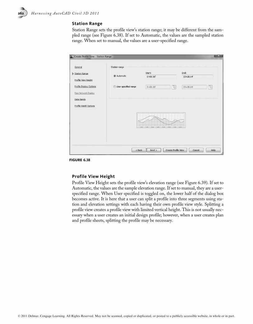
Station RangeStation Range sets the profile view’s station range; it may be different from the sam-pled range (see Figure 6.38). If set to Automatic, the values are the sampled stationrange. When set to manual, the values are a user-specified range.
Profile View HeightProfile View Height sets the profile view’s elevation range (see Figure 6.39). If set toAutomatic, the values are the sample elevation range. If set to manual, they are a user-specified range. When User specified is toggled on, the lower half of the dialog boxbecomes active. It is here that a user can split a profile into three segments using sta-tion and elevation settings with each having their own profile view style. Splitting aprofile view creates a profile view with limited vertical height. This is not usually nec-essary when a user creates an initial design profile; however, when a user creates planand profile sheets, splitting the profile may be necessary.
FIGURE 6.38
© 2011 Delmar, Cengage Learning. All Rights Reserved. May not be scanned, copied or duplicated, or posted to a publicly accessible website, in whole or in part.
262 Harn e s s i n g Au t oCAD Civ i l 3D 2011

Profile Display OptionsProfile Display Options determine which profiles to display and their mode, it setstheir object and label styles, and it reviews their station and elevation values (see Fig-ure 6.40).
FIGURE 6.39
FIGURE 6.40
© 2011 Delmar, Cengage Learning. All Rights Reserved. May not be scanned, copied or duplicated, or posted to a publicly accessible website, in whole or in part.
Chap t e r 6 • Pr o f i l e V i ew s and P r o f i l e s 263

Pipe Network DisplayPipe Network Display selects entire pipe networks or their pipes and structures todraw in a profile view (see Figure 6.41). By selecting a network, all of its pipes andstructures are selected. The Show only parts selected to draw in profile view drawsonly selected parts in the profile view.
Data BandsData Bands sets the Band Set (top), its location (middle), and its properties (bottom) (seeFigure 6.42).When you are creating the initial profile view, there is usually only one pro-file. In this case, the wizard assigns the surface profile to Profile1 and Profile2.When youare defining the second profile, youmust change Profile2’s assignment to the new profile.
FIGURE 6.41
FIGURE 6.42
© 2011 Delmar, Cengage Learning. All Rights Reserved. May not be scanned, copied or duplicated, or posted to a publicly accessible website, in whole or in part.
264 Harn e s s i n g Au t oCAD Civ i l 3D 2011

SUMMARY
• The Create Profile from Surface command samples one, all, or any combinationof surfaces.
• The Create Profile or Create Profile View dialog box select which profiles appearin a profile view.
• A Profile View can pad the grid area around a profile.
• A Profile View can clip the horizontal or vertical view grid.
• A Profile View’s annotation is around its grid perimeter.
• A Profile style assigns a component’s layer name and properties.
• A Profile’s annotation is within a profile view’s grid.
• Profile View label styles are placed after the profile(s) and the views are created.
UNIT 3: DESIGNING A PROPOSED PROFILE
Within the profile view and its existing ground profile, a designer creates a verticalroad design. This design goes by many names: vertical alignment, finished ground,etc. A vertical alignment contains proposed tangents (lines) and vertical curvesegments.
Vertical curves transition a vehicle from one grade to the next. There are two types ofvertical curves: crest (transitioning from an up to a down grade) or sag (transitioningfrom a down to an up grade). There are three vertical curve types: circular, asymmet-rical (parabolic), and parabolic. The parameters to create these curves are curve lengthor a K Value. A K Value represents the horizontal distance along which a 1 percentchange in grade occurs on the vertical curve and is a measure of abruptness.
PROFILE CREATION TOOLSThe Home tab’s Create Design panel’s Profile – Profile Creation Tools toolbar hasseveral commands creating a design profile. See Figure 6.43.
Create Best Fit ProfileThe Create Best Fit Profile uses cogo points projected into a profile and sorted bystation to create tangent segments. If the points also define a curve, the routine willcreate an arc or parabola up to a user-specified value. If the points create a curve ex-ceeding this value, the routine creates a PVI. This routine also uses 3D polylines andfeature lines.
Create Profile from FileThis routine reads a file containing station and elevation values to create a profile.The file must have a starting and ending station value with elevations. The file canalso include vertical curve lengths. There cannot be a vertical curve at the beginningor end of a profile. Following is an example of a profile file that starts at station 1000and ends at station 6300.
1000 1100.25
1050 1004.25
2000 1009.00 140.0
© 2011 Delmar, Cengage Learning. All Rights Reserved. May not be scanned, copied or duplicated, or posted to a publicly accessible website, in whole or in part.
Chap t e r 6 • Pr o f i l e V i ew s and P r o f i l e s 265

3550 1020.65
4200 998.15 135.0
5250 1002.45
6300 1005.85
Create Superimposed ProfileThe routine creates a copy of a profile from another profile view and places the copy ina second profile view. For example, a cul-de-sac has profiles for the bulb’s gutter linealignment and you want to place a copy of it into the cul-de-sac’s centerline profile.This allows you to evaluate the differences between the two profiles within the sameprofile view.
Create Profile from CorridorThis routine creates a profile from a corridor feature line. This routine is essentialwhen wanting to develop vertical control for a corridor. The routine uses the corri-dor’s feature line’s current vertical values and places them in a profile view where youcan refine their values with the profile editing tools.
Profile Creation ToolsThe tools of the Profile Creation Tools toolbar are for designing a vertical alignment’stangent and curve segments (see Figure 6.44). After starting the command and iden-tifying the profile view, the Create Profile dialog box opens with two tabs assigningsite, styles, and design criteria.
FIGURE 6.43
© 2011 Delmar, Cengage Learning. All Rights Reserved. May not be scanned, copied or duplicated, or posted to a publicly accessible website, in whole or in part.
266 Harn e s s i n g Au t oCAD Civ i l 3D 2011

After setting the values in the Create Profile dialog box, click OK to display the Pro-file Layout Tools toolbar. Minimally, you can draft tangent (line) segments and lateradd the vertical curves to the alignment.
Clicking the toolbar’s leftmost icon’s drop-list arrow lists its available drafting modes:draw tangents only and tangents with vertical curves. The last item listed sets the ver-tical curve default values: curve length or K Value. The default type, length, and de-sign values are from Profile’s Edit Feature Settings (see Figure 6.45).
FIGURE 6.44
FIGURE 6.45
© 2011 Delmar, Cengage Learning. All Rights Reserved. May not be scanned, copied or duplicated, or posted to a publicly accessible website, in whole or in part.
Chap t e r 6 • Pr o f i l e V i ew s and P r o f i l e s 267

The toolbar’s next three icons insert, delete, or move tangent Points of Vertical Inter-section (PVIs).
TangentsTangents’ icon stack creates three tangent types; fixed, floating, and free (see Figure6.46). You draft a fixed tangent by selecting two points, a floating tangent attaches tothe end of an existing vertical curve, and a free tangent is drawn between two existingvertical curves. Fixed and Floating also use a best fit drawingmethod. The Solve TangentIntersection routine creates intersection tangents even though they may not intersect.
CurvesThe Curves’ icon stack drafts fixed, floating, and free vertical curves. See Figure 6.47.
FixedA fixed curve segment does not connect to or depend on preexisting segments. Fixedvertical curves have several variations: three points; best fit; selecting an endpoint andidentifying a pass-through point; selecting two points and entering in the tangentgrade at the start of the vertical curve; selecting two points and entering in the tangentgrade at the end of the vertical curve; and selecting two points and entering a param-eter (K or minimum radius).
NOTE When describing fixed segments, think of zero dependencies.
Floating. Floating vertical curves have three variations: selecting an existing segmentto attach to and identifying a pass-through point and a K value; selecting an existingsegment to attach to and identifying a pass-through point and a grade; or using a best-fit method.
NOTE When describing floating segments, think of one dependency.
Free. Free vertical curves have three variations: selecting two existing segments andspecifying a K value or a radius; using a best-fit method; or selecting two existing seg-ments and specifying a parabolic, asymmetrical parabolic, or circular vertical curve andsetting additional parameters.
NOTE When describing of free segments, think of two dependencies.
FIGURE 6.46
© 2011 Delmar, Cengage Learning. All Rights Reserved. May not be scanned, copied or duplicated, or posted to a publicly accessible website, in whole or in part.
268 Harn e s s i n g Au t oCAD Civ i l 3D 2011
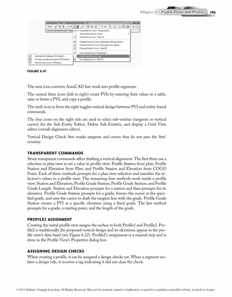
The next icon converts AutoCAD line work into profile segments.
The central three icons (left to right) create PVIs by entering their values in a table,raise or lower a PVI, and copy a profile.
The sixth icon in from the right toggles vertical design between PVI and entity-basedcommands.
The four icons on the right side are used to select sub-entities (tangents or verticalcurves) for the Sub-Entity Editor, Delete Sub-Entities, and display a Grid Vieweditor (overall alignment editor).
Vertical Design Check Sets marks tangents and curves that do not pass the Sets’scrutiny.
TRANSPARENT COMMANDSSeven transparent commands affect drafting a vertical alignment. The first three use aselection in plan view to set a value in profile view: Profile Station from plan; ProfileStation and Elevation from Plan; and Profile Station and Elevation from COGOPoint. Each of these methods prompts for a plan view selection and transfers the se-lection’s values to a profile view. The remaining four methods work inside a profileview: Station and Elevation; Profile Grade Station; Profile Grade Station; and ProfileGrade Length. Station and Elevation prompts for a station and then prompts for itselevation. Profile Grade Station prompts for a grade, freezes the cursor at the speci-fied grade, and uses the cursor to draft the tangent line with the grade. Profile GradeStation creates a PVI at a specific elevation using a fixed grade. The last methodprompts for a grade, a starting point, and the length of the grade.
PROFILE2 ASSIGNMENTCreating the initial profile view assigns the surface to both Profile1 and Profile2. Pro-file2 is traditionally the proposed vertical design and its elevations appear in the pro-file view’s data band (see Figure 6.12). Profile2’s assignment is a manual step and isdone in the Profile View’s Properties dialog box.
ASSIGNING DESIGN CHECKSWhen creating a profile, it can be assigned a design checks set. When a segment vio-lates a design rule, it receives a tag indicating it did not clear the check.
FIGURE 6.47
© 2011 Delmar, Cengage Learning. All Rights Reserved. May not be scanned, copied or duplicated, or posted to a publicly accessible website, in whole or in part.
Chap t e r 6 • Pr o f i l e V i ew s and P r o f i l e s 269

EDIT LABELS…If you are not adding labels while designing a profile, Edit Labels… adds or changeslabels assigned to a profile. In the drawing, select a profile, press the right mouse but-ton, and from the shortcut menu, select Edit Labels…. The Profile Labels dialog boxlists currently assigned label types and styles (see Figure 6.48). The Add control al-lows for label additions to the current list and the Delete button deletes any assignedlabel type and style. The dialog box’s top right sets the label type and style to add, andat the bottom are controls to import a profile label set or to create one from the cur-rent label list.
SUMMARY
• Profile’s Edit Feature Settings dialog box values set the vertical curve’s type,criteria, and calculation values.
• There are three vertical curve types: circular, symmetrical, and asymmetricalparabolic curves.
• There are three plan view vertical design transparent commands: Profile Stationfrom Plan; Profile Station and Elevation from Plan; and Profile Station and Eleva-tion from COGO Point.
• There are three profile view vertical design transparent commands: ProfileStation Elevation; Profile Grade Station; and Profile Grade Length.
• You can create an initial vertical design with or without vertical curves.
• If you are creating an initial design with only tangent segments, you can addvertical curves at anytime.
• If you are creating overlapping vertical curves, the routine issues cannot resolveerror and start prompting you for new values.
• If you are drafting an initial vertical design with tangents and vertical curves andthere is no solution for a vertical curve, the routine will not draw a vertical curve.
FIGURE 6.48
© 2011 Delmar, Cengage Learning. All Rights Reserved. May not be scanned, copied or duplicated, or posted to a publicly accessible website, in whole or in part.
270 Harn e s s i n g Au t oCAD Civ i l 3D 2011

UNIT 4: ANALYZING AND EDITING A VERTICAL DESIGN
Vertical alignment analysis and editing is this unit’s focus. The vertical design analysisuses Toolbox reports or information displayed in the Profile Layout Tools toolbar’sGrid View or Sub-entity editors. Also, grips graphically edit a design profile. TheInquiry Tool palette has profile and profile inquiry commands.
PROFILE REPORTSToolbox has several profile reports (see Figure 6.49). In Toolbox, select the reporttype, right mouse click, and from the shortcut menu, select Execute…. Dependingon the report type, a user selects the profile or enters a Create Reports dialog box.Here, a user selects the profile and continues to generate the report.
INQUIRY TOOLInquiry Tool has two profile view and profile inquiries (see Figure 6.50). The profileview inquiries are Profile View Station and Elevation at Point and Profile View Ele-vation and Grade between Points. The Profile inquiries are Profile Station and Ele-vation at Point and Profile Elevation Difference at Station. Both query sets promptfor the surface and profiles. After selecting a point or point(s), the Inquiry Tool pal-ette populates and displays the query results.
FIGURE 6.49
© 2011 Delmar, Cengage Learning. All Rights Reserved. May not be scanned, copied or duplicated, or posted to a publicly accessible website, in whole or in part.
Chap t e r 6 • Pr o f i l e V i ew s and P r o f i l e s 271

GRAPHICAL EDITINGProfile grips graphically manipulate its PVIs and segments. When selecting a profile,Profile displays grips to edit a vertical curve’s length, change its PVI location and ele-vation, or move a PVI by holding one tangent’s grade and changing the second tan-gent’s grade. When manipulating a PVI’s grip, all connected tangents change toaccommodate its new location (see Figure 6.51).
Each grip type has a specific editing function. For example, round grips at a verticalcurve’s end and midpoints lengthen the curve. PVI right and left arrow grips hold one
FIGURE 6.50
FIGURE 6.51
© 2011 Delmar, Cengage Learning. All Rights Reserved. May not be scanned, copied or duplicated, or posted to a publicly accessible website, in whole or in part.
272 Harn e s s i n g Au t oCAD Civ i l 3D 2011

tangent’s grade while moving the PVI and changing the second tangent’s grade. APVI red triangle grip adjusts both tangent grades, which changes the PVI’s location.
PROFILE LAYOUT TOOLS EDITORSThe Profile Layout Tools toolbar provides two editors for reviewing and editing pro-file tangent and vertical curve values: Grid View displays all vertical alignment values;and Profile Layout Parameters displays selected vertical segment values. Figure 6.52shows the Profile Layout Parameter dialog box.
Making any adjustments in either editor causes the profile to recalculate and it is thenredisplayed with its new values. Each editor indicates editable values with black print.
SUMMARY
• Toolbox reports a profile’s station, elevation, grades, and length of vertical curves.
• When you are graphically editing a vertical curve, manipulate its grips linked tospecific geometric PVI and vertical curve points.
• When you are graphically editing a profile, round grips affect vertical curves.
• When you are graphically editing a profile, arrow grips affect the PVI’s locationby holding the first or second grade.
• When you are graphically editing a profile, by selecting the triangular PVI grip, youchange its location, the in and out grades, the PVI elevation, and/or the PVI station.
UNIT 5: PROFILE ANNOTATION
This unit reviews profile view annotation. A design profile can be annotated as it iscreated or after it has been created. This concept was reviewed earlier in this chapter.
FIGURE 6.52
© 2011 Delmar, Cengage Learning. All Rights Reserved. May not be scanned, copied or duplicated, or posted to a publicly accessible website, in whole or in part.
Chap t e r 6 • Pr o f i l e V i ew s and P r o f i l e s 273

SPOT PROFILE LABELSA second profile annotation type is Profile View labels to annotate stations and eleva-tions. The Add Labels, Profile Views menu, Add Profile View Labels command cre-ates these label types: Station and Elevation and Depth. The Station and Elevationlabel annotates its namesake at user-selected locations (see Figure 6.53). After identi-fying the profile view, a jig appears connecting the stationing along the profile’s bot-tom to the cursor. After selecting the station, the jig freezes at the station and itswitches to identify the elevation.
Depth annotates the distance between two selected points. If you are selecting a lowerthen a higher point, the label is a positive grade. If you are selecting a higher and thena lower point, the label is a negative grade.
PROJECTING OBJECTS TO PROFILE AND SECTION VIEWSCivil 3D projects AutoCAD points, blocks, 3D solids and 3D polylines, Civil 3DCOGO points, feature lines, and survey figures to a profile and/or section view. Theobjects must exist in the drawing before projecting them to a view and CANNOTstart and end after the profile stationing. If the object’s type is not correct, the routineremoves it from the projection selection set. A projected object may represent a wa-terline, cable line, electric lines, ROW lines for a profile and/or section, etc.
After drafting the object, in the Profile or Profile View ribbon tab, the Launch Padpanel’s right side, you select Project Objects to Profile View. After selecting the ob-jects to project and the profile/section view, the Project Objects to Profile/SectionView dialog box displays (see Figure 6.54). In the Project Objects to Profile Viewdialog box, for each selected object, you select a style, an elevation option, and if de-sired, a label style.
FIGURE 6.53
© 2011 Delmar, Cengage Learning. All Rights Reserved. May not be scanned, copied or duplicated, or posted to a publicly accessible website, in whole or in part.
274 Harn e s s i n g Au t oCAD Civ i l 3D 2011

Projection StylesA projected object style defines both profile and section behavior and is found inSetting’s Multipurpose section. The Information tab supplies the style’s name.The Profile and Section panels define the behavior for all possible object types (seeFigure 6.55). You select the object type from a list by clicking the drop-list arrow at
FIGURE 6.54
FIGURE 6.55
© 2011 Delmar, Cengage Learning. All Rights Reserved. May not be scanned, copied or duplicated, or posted to a publicly accessible website, in whole or in part.
Chap t e r 6 • Pr o f i l e V i ew s and P r o f i l e s 275

the panel’s top left. Each object type has a unique properties list. Both Profile andSection have the same object type and properties list. The Display panel sets the pro-file and section layers and their properties. The Display tab sets the projection object’slayers (see Figure 6.56).
SUMMARY
• Station and Elevation are profile view labels.
• Depth labels the distance between select points within a profile view.
This ends the Profiles and Profile Views Chapter. The next chapter focuses on theAssembly, its subassemblies, and the roadway model, the corridor.
FIGURE 6.56
© 2011 Delmar, Cengage Learning. All Rights Reserved. May not be scanned, copied or duplicated, or posted to a publicly accessible website, in whole or in part.
276 Harn e s s i n g Au t oCAD Civ i l 3D 2011